JP7161998B2 - Implant with protected fusion area - Google Patents
Implant with protected fusion area Download PDFInfo
- Publication number
- JP7161998B2 JP7161998B2 JP2019543183A JP2019543183A JP7161998B2 JP 7161998 B2 JP7161998 B2 JP 7161998B2 JP 2019543183 A JP2019543183 A JP 2019543183A JP 2019543183 A JP2019543183 A JP 2019543183A JP 7161998 B2 JP7161998 B2 JP 7161998B2
- Authority
- JP
- Japan
- Prior art keywords
- implant
- outer member
- support member
- surface area
- geometry
- Prior art date
- Legal status (The legal status is an assumption and is not a legal conclusion. Google has not performed a legal analysis and makes no representation as to the accuracy of the status listed.)
- Active
Links
Images


Classifications
-
- A—HUMAN NECESSITIES
- A61—MEDICAL OR VETERINARY SCIENCE; HYGIENE
- A61F—FILTERS IMPLANTABLE INTO BLOOD VESSELS; PROSTHESES; DEVICES PROVIDING PATENCY TO, OR PREVENTING COLLAPSING OF, TUBULAR STRUCTURES OF THE BODY, e.g. STENTS; ORTHOPAEDIC, NURSING OR CONTRACEPTIVE DEVICES; FOMENTATION; TREATMENT OR PROTECTION OF EYES OR EARS; BANDAGES, DRESSINGS OR ABSORBENT PADS; FIRST-AID KITS
- A61F2/00—Filters implantable into blood vessels; Prostheses, i.e. artificial substitutes or replacements for parts of the body; Appliances for connecting them with the body; Devices providing patency to, or preventing collapsing of, tubular structures of the body, e.g. stents
- A61F2/02—Prostheses implantable into the body
- A61F2/30—Joints
- A61F2/44—Joints for the spine, e.g. vertebrae, spinal discs
- A61F2/4455—Joints for the spine, e.g. vertebrae, spinal discs for the fusion of spinal bodies, e.g. intervertebral fusion of adjacent spinal bodies, e.g. fusion cages
- A61F2/447—Joints for the spine, e.g. vertebrae, spinal discs for the fusion of spinal bodies, e.g. intervertebral fusion of adjacent spinal bodies, e.g. fusion cages substantially parallelepipedal, e.g. having a rectangular or trapezoidal cross-section
-
- A—HUMAN NECESSITIES
- A61—MEDICAL OR VETERINARY SCIENCE; HYGIENE
- A61F—FILTERS IMPLANTABLE INTO BLOOD VESSELS; PROSTHESES; DEVICES PROVIDING PATENCY TO, OR PREVENTING COLLAPSING OF, TUBULAR STRUCTURES OF THE BODY, e.g. STENTS; ORTHOPAEDIC, NURSING OR CONTRACEPTIVE DEVICES; FOMENTATION; TREATMENT OR PROTECTION OF EYES OR EARS; BANDAGES, DRESSINGS OR ABSORBENT PADS; FIRST-AID KITS
- A61F2/00—Filters implantable into blood vessels; Prostheses, i.e. artificial substitutes or replacements for parts of the body; Appliances for connecting them with the body; Devices providing patency to, or preventing collapsing of, tubular structures of the body, e.g. stents
- A61F2/02—Prostheses implantable into the body
- A61F2/30—Joints
- A61F2/3094—Designing or manufacturing processes
- A61F2/30942—Designing or manufacturing processes for designing or making customized prostheses, e.g. using templates, CT or NMR scans, finite-element analysis or CAD-CAM techniques
-
- A—HUMAN NECESSITIES
- A61—MEDICAL OR VETERINARY SCIENCE; HYGIENE
- A61F—FILTERS IMPLANTABLE INTO BLOOD VESSELS; PROSTHESES; DEVICES PROVIDING PATENCY TO, OR PREVENTING COLLAPSING OF, TUBULAR STRUCTURES OF THE BODY, e.g. STENTS; ORTHOPAEDIC, NURSING OR CONTRACEPTIVE DEVICES; FOMENTATION; TREATMENT OR PROTECTION OF EYES OR EARS; BANDAGES, DRESSINGS OR ABSORBENT PADS; FIRST-AID KITS
- A61F2/00—Filters implantable into blood vessels; Prostheses, i.e. artificial substitutes or replacements for parts of the body; Appliances for connecting them with the body; Devices providing patency to, or preventing collapsing of, tubular structures of the body, e.g. stents
- A61F2/02—Prostheses implantable into the body
- A61F2/30—Joints
- A61F2/44—Joints for the spine, e.g. vertebrae, spinal discs
- A61F2/4455—Joints for the spine, e.g. vertebrae, spinal discs for the fusion of spinal bodies, e.g. intervertebral fusion of adjacent spinal bodies, e.g. fusion cages
- A61F2/446—Joints for the spine, e.g. vertebrae, spinal discs for the fusion of spinal bodies, e.g. intervertebral fusion of adjacent spinal bodies, e.g. fusion cages having a circular or elliptical cross-section substantially parallel to the axis of the spine, e.g. cylinders or frustocones
-
- A—HUMAN NECESSITIES
- A61—MEDICAL OR VETERINARY SCIENCE; HYGIENE
- A61B—DIAGNOSIS; SURGERY; IDENTIFICATION
- A61B17/00—Surgical instruments, devices or methods, e.g. tourniquets
- A61B17/56—Surgical instruments or methods for treatment of bones or joints; Devices specially adapted therefor
- A61B17/58—Surgical instruments or methods for treatment of bones or joints; Devices specially adapted therefor for osteosynthesis, e.g. bone plates, screws, setting implements or the like
- A61B17/68—Internal fixation devices, including fasteners and spinal fixators, even if a part thereof projects from the skin
- A61B17/84—Fasteners therefor or fasteners being internal fixation devices
- A61B17/86—Pins or screws or threaded wires; nuts therefor
- A61B2017/8655—Pins or screws or threaded wires; nuts therefor with special features for locking in the bone
-
- A—HUMAN NECESSITIES
- A61—MEDICAL OR VETERINARY SCIENCE; HYGIENE
- A61F—FILTERS IMPLANTABLE INTO BLOOD VESSELS; PROSTHESES; DEVICES PROVIDING PATENCY TO, OR PREVENTING COLLAPSING OF, TUBULAR STRUCTURES OF THE BODY, e.g. STENTS; ORTHOPAEDIC, NURSING OR CONTRACEPTIVE DEVICES; FOMENTATION; TREATMENT OR PROTECTION OF EYES OR EARS; BANDAGES, DRESSINGS OR ABSORBENT PADS; FIRST-AID KITS
- A61F2/00—Filters implantable into blood vessels; Prostheses, i.e. artificial substitutes or replacements for parts of the body; Appliances for connecting them with the body; Devices providing patency to, or preventing collapsing of, tubular structures of the body, e.g. stents
- A61F2/02—Prostheses implantable into the body
- A61F2/30—Joints
- A61F2/30721—Accessories
- A61F2/30744—End caps, e.g. for closing an endoprosthetic cavity
-
- A—HUMAN NECESSITIES
- A61—MEDICAL OR VETERINARY SCIENCE; HYGIENE
- A61F—FILTERS IMPLANTABLE INTO BLOOD VESSELS; PROSTHESES; DEVICES PROVIDING PATENCY TO, OR PREVENTING COLLAPSING OF, TUBULAR STRUCTURES OF THE BODY, e.g. STENTS; ORTHOPAEDIC, NURSING OR CONTRACEPTIVE DEVICES; FOMENTATION; TREATMENT OR PROTECTION OF EYES OR EARS; BANDAGES, DRESSINGS OR ABSORBENT PADS; FIRST-AID KITS
- A61F2/00—Filters implantable into blood vessels; Prostheses, i.e. artificial substitutes or replacements for parts of the body; Appliances for connecting them with the body; Devices providing patency to, or preventing collapsing of, tubular structures of the body, e.g. stents
- A61F2/02—Prostheses implantable into the body
- A61F2/30—Joints
- A61F2/30767—Special external or bone-contacting surface, e.g. coating for improving bone ingrowth
- A61F2/30771—Special external or bone-contacting surface, e.g. coating for improving bone ingrowth applied in original prostheses, e.g. holes or grooves
-
- A—HUMAN NECESSITIES
- A61—MEDICAL OR VETERINARY SCIENCE; HYGIENE
- A61F—FILTERS IMPLANTABLE INTO BLOOD VESSELS; PROSTHESES; DEVICES PROVIDING PATENCY TO, OR PREVENTING COLLAPSING OF, TUBULAR STRUCTURES OF THE BODY, e.g. STENTS; ORTHOPAEDIC, NURSING OR CONTRACEPTIVE DEVICES; FOMENTATION; TREATMENT OR PROTECTION OF EYES OR EARS; BANDAGES, DRESSINGS OR ABSORBENT PADS; FIRST-AID KITS
- A61F2/00—Filters implantable into blood vessels; Prostheses, i.e. artificial substitutes or replacements for parts of the body; Appliances for connecting them with the body; Devices providing patency to, or preventing collapsing of, tubular structures of the body, e.g. stents
- A61F2/02—Prostheses implantable into the body
- A61F2/30—Joints
- A61F2/46—Special tools or methods for implanting or extracting artificial joints, accessories, bone grafts or substitutes, or particular adaptations therefor
- A61F2/4603—Special tools or methods for implanting or extracting artificial joints, accessories, bone grafts or substitutes, or particular adaptations therefor for insertion or extraction of endoprosthetic joints or of accessories thereof
- A61F2/4611—Special tools or methods for implanting or extracting artificial joints, accessories, bone grafts or substitutes, or particular adaptations therefor for insertion or extraction of endoprosthetic joints or of accessories thereof of spinal prostheses
-
- A—HUMAN NECESSITIES
- A61—MEDICAL OR VETERINARY SCIENCE; HYGIENE
- A61F—FILTERS IMPLANTABLE INTO BLOOD VESSELS; PROSTHESES; DEVICES PROVIDING PATENCY TO, OR PREVENTING COLLAPSING OF, TUBULAR STRUCTURES OF THE BODY, e.g. STENTS; ORTHOPAEDIC, NURSING OR CONTRACEPTIVE DEVICES; FOMENTATION; TREATMENT OR PROTECTION OF EYES OR EARS; BANDAGES, DRESSINGS OR ABSORBENT PADS; FIRST-AID KITS
- A61F2/00—Filters implantable into blood vessels; Prostheses, i.e. artificial substitutes or replacements for parts of the body; Appliances for connecting them with the body; Devices providing patency to, or preventing collapsing of, tubular structures of the body, e.g. stents
- A61F2/02—Prostheses implantable into the body
- A61F2/30—Joints
- A61F2002/30001—Additional features of subject-matter classified in A61F2/28, A61F2/30 and subgroups thereof
- A61F2002/30003—Material related properties of the prosthesis or of a coating on the prosthesis
- A61F2002/30004—Material related properties of the prosthesis or of a coating on the prosthesis the prosthesis being made from materials having different values of a given property at different locations within the same prosthesis
- A61F2002/30011—Material related properties of the prosthesis or of a coating on the prosthesis the prosthesis being made from materials having different values of a given property at different locations within the same prosthesis differing in porosity
-
- A—HUMAN NECESSITIES
- A61—MEDICAL OR VETERINARY SCIENCE; HYGIENE
- A61F—FILTERS IMPLANTABLE INTO BLOOD VESSELS; PROSTHESES; DEVICES PROVIDING PATENCY TO, OR PREVENTING COLLAPSING OF, TUBULAR STRUCTURES OF THE BODY, e.g. STENTS; ORTHOPAEDIC, NURSING OR CONTRACEPTIVE DEVICES; FOMENTATION; TREATMENT OR PROTECTION OF EYES OR EARS; BANDAGES, DRESSINGS OR ABSORBENT PADS; FIRST-AID KITS
- A61F2/00—Filters implantable into blood vessels; Prostheses, i.e. artificial substitutes or replacements for parts of the body; Appliances for connecting them with the body; Devices providing patency to, or preventing collapsing of, tubular structures of the body, e.g. stents
- A61F2/02—Prostheses implantable into the body
- A61F2/30—Joints
- A61F2002/30001—Additional features of subject-matter classified in A61F2/28, A61F2/30 and subgroups thereof
- A61F2002/30003—Material related properties of the prosthesis or of a coating on the prosthesis
- A61F2002/30004—Material related properties of the prosthesis or of a coating on the prosthesis the prosthesis being made from materials having different values of a given property at different locations within the same prosthesis
- A61F2002/30028—Material related properties of the prosthesis or of a coating on the prosthesis the prosthesis being made from materials having different values of a given property at different locations within the same prosthesis differing in tissue ingrowth capacity, e.g. made from both ingrowth-promoting and ingrowth-preventing parts
-
- A—HUMAN NECESSITIES
- A61—MEDICAL OR VETERINARY SCIENCE; HYGIENE
- A61F—FILTERS IMPLANTABLE INTO BLOOD VESSELS; PROSTHESES; DEVICES PROVIDING PATENCY TO, OR PREVENTING COLLAPSING OF, TUBULAR STRUCTURES OF THE BODY, e.g. STENTS; ORTHOPAEDIC, NURSING OR CONTRACEPTIVE DEVICES; FOMENTATION; TREATMENT OR PROTECTION OF EYES OR EARS; BANDAGES, DRESSINGS OR ABSORBENT PADS; FIRST-AID KITS
- A61F2/00—Filters implantable into blood vessels; Prostheses, i.e. artificial substitutes or replacements for parts of the body; Appliances for connecting them with the body; Devices providing patency to, or preventing collapsing of, tubular structures of the body, e.g. stents
- A61F2/02—Prostheses implantable into the body
- A61F2/30—Joints
- A61F2002/30001—Additional features of subject-matter classified in A61F2/28, A61F2/30 and subgroups thereof
- A61F2002/30108—Shapes
- A61F2002/3011—Cross-sections or two-dimensional shapes
- A61F2002/30112—Rounded shapes, e.g. with rounded corners
- A61F2002/30113—Rounded shapes, e.g. with rounded corners circular
- A61F2002/30116—Rounded shapes, e.g. with rounded corners circular partial circles, i.e. circular segments
-
- A—HUMAN NECESSITIES
- A61—MEDICAL OR VETERINARY SCIENCE; HYGIENE
- A61F—FILTERS IMPLANTABLE INTO BLOOD VESSELS; PROSTHESES; DEVICES PROVIDING PATENCY TO, OR PREVENTING COLLAPSING OF, TUBULAR STRUCTURES OF THE BODY, e.g. STENTS; ORTHOPAEDIC, NURSING OR CONTRACEPTIVE DEVICES; FOMENTATION; TREATMENT OR PROTECTION OF EYES OR EARS; BANDAGES, DRESSINGS OR ABSORBENT PADS; FIRST-AID KITS
- A61F2/00—Filters implantable into blood vessels; Prostheses, i.e. artificial substitutes or replacements for parts of the body; Appliances for connecting them with the body; Devices providing patency to, or preventing collapsing of, tubular structures of the body, e.g. stents
- A61F2/02—Prostheses implantable into the body
- A61F2/30—Joints
- A61F2002/30001—Additional features of subject-matter classified in A61F2/28, A61F2/30 and subgroups thereof
- A61F2002/30108—Shapes
- A61F2002/3011—Cross-sections or two-dimensional shapes
- A61F2002/30112—Rounded shapes, e.g. with rounded corners
- A61F2002/30125—Rounded shapes, e.g. with rounded corners elliptical or oval
-
- A—HUMAN NECESSITIES
- A61—MEDICAL OR VETERINARY SCIENCE; HYGIENE
- A61F—FILTERS IMPLANTABLE INTO BLOOD VESSELS; PROSTHESES; DEVICES PROVIDING PATENCY TO, OR PREVENTING COLLAPSING OF, TUBULAR STRUCTURES OF THE BODY, e.g. STENTS; ORTHOPAEDIC, NURSING OR CONTRACEPTIVE DEVICES; FOMENTATION; TREATMENT OR PROTECTION OF EYES OR EARS; BANDAGES, DRESSINGS OR ABSORBENT PADS; FIRST-AID KITS
- A61F2/00—Filters implantable into blood vessels; Prostheses, i.e. artificial substitutes or replacements for parts of the body; Appliances for connecting them with the body; Devices providing patency to, or preventing collapsing of, tubular structures of the body, e.g. stents
- A61F2/02—Prostheses implantable into the body
- A61F2/30—Joints
- A61F2002/30001—Additional features of subject-matter classified in A61F2/28, A61F2/30 and subgroups thereof
- A61F2002/30108—Shapes
- A61F2002/3011—Cross-sections or two-dimensional shapes
- A61F2002/30112—Rounded shapes, e.g. with rounded corners
- A61F2002/30136—Rounded shapes, e.g. with rounded corners undulated or wavy, e.g. serpentine-shaped or zigzag-shaped
-
- A—HUMAN NECESSITIES
- A61—MEDICAL OR VETERINARY SCIENCE; HYGIENE
- A61F—FILTERS IMPLANTABLE INTO BLOOD VESSELS; PROSTHESES; DEVICES PROVIDING PATENCY TO, OR PREVENTING COLLAPSING OF, TUBULAR STRUCTURES OF THE BODY, e.g. STENTS; ORTHOPAEDIC, NURSING OR CONTRACEPTIVE DEVICES; FOMENTATION; TREATMENT OR PROTECTION OF EYES OR EARS; BANDAGES, DRESSINGS OR ABSORBENT PADS; FIRST-AID KITS
- A61F2/00—Filters implantable into blood vessels; Prostheses, i.e. artificial substitutes or replacements for parts of the body; Appliances for connecting them with the body; Devices providing patency to, or preventing collapsing of, tubular structures of the body, e.g. stents
- A61F2/02—Prostheses implantable into the body
- A61F2/30—Joints
- A61F2002/30001—Additional features of subject-matter classified in A61F2/28, A61F2/30 and subgroups thereof
- A61F2002/30108—Shapes
- A61F2002/3011—Cross-sections or two-dimensional shapes
- A61F2002/30159—Concave polygonal shapes
- A61F2002/30172—T-shaped
-
- A—HUMAN NECESSITIES
- A61—MEDICAL OR VETERINARY SCIENCE; HYGIENE
- A61F—FILTERS IMPLANTABLE INTO BLOOD VESSELS; PROSTHESES; DEVICES PROVIDING PATENCY TO, OR PREVENTING COLLAPSING OF, TUBULAR STRUCTURES OF THE BODY, e.g. STENTS; ORTHOPAEDIC, NURSING OR CONTRACEPTIVE DEVICES; FOMENTATION; TREATMENT OR PROTECTION OF EYES OR EARS; BANDAGES, DRESSINGS OR ABSORBENT PADS; FIRST-AID KITS
- A61F2/00—Filters implantable into blood vessels; Prostheses, i.e. artificial substitutes or replacements for parts of the body; Appliances for connecting them with the body; Devices providing patency to, or preventing collapsing of, tubular structures of the body, e.g. stents
- A61F2/02—Prostheses implantable into the body
- A61F2/30—Joints
- A61F2002/30001—Additional features of subject-matter classified in A61F2/28, A61F2/30 and subgroups thereof
- A61F2002/30108—Shapes
- A61F2002/30199—Three-dimensional shapes
- A61F2002/30289—Three-dimensional shapes helically-coiled
-
- A—HUMAN NECESSITIES
- A61—MEDICAL OR VETERINARY SCIENCE; HYGIENE
- A61F—FILTERS IMPLANTABLE INTO BLOOD VESSELS; PROSTHESES; DEVICES PROVIDING PATENCY TO, OR PREVENTING COLLAPSING OF, TUBULAR STRUCTURES OF THE BODY, e.g. STENTS; ORTHOPAEDIC, NURSING OR CONTRACEPTIVE DEVICES; FOMENTATION; TREATMENT OR PROTECTION OF EYES OR EARS; BANDAGES, DRESSINGS OR ABSORBENT PADS; FIRST-AID KITS
- A61F2/00—Filters implantable into blood vessels; Prostheses, i.e. artificial substitutes or replacements for parts of the body; Appliances for connecting them with the body; Devices providing patency to, or preventing collapsing of, tubular structures of the body, e.g. stents
- A61F2/02—Prostheses implantable into the body
- A61F2/30—Joints
- A61F2002/30001—Additional features of subject-matter classified in A61F2/28, A61F2/30 and subgroups thereof
- A61F2002/30108—Shapes
- A61F2002/30199—Three-dimensional shapes
- A61F2002/30291—Three-dimensional shapes spirally-coiled, i.e. having a 2D spiral cross-section
-
- A—HUMAN NECESSITIES
- A61—MEDICAL OR VETERINARY SCIENCE; HYGIENE
- A61F—FILTERS IMPLANTABLE INTO BLOOD VESSELS; PROSTHESES; DEVICES PROVIDING PATENCY TO, OR PREVENTING COLLAPSING OF, TUBULAR STRUCTURES OF THE BODY, e.g. STENTS; ORTHOPAEDIC, NURSING OR CONTRACEPTIVE DEVICES; FOMENTATION; TREATMENT OR PROTECTION OF EYES OR EARS; BANDAGES, DRESSINGS OR ABSORBENT PADS; FIRST-AID KITS
- A61F2/00—Filters implantable into blood vessels; Prostheses, i.e. artificial substitutes or replacements for parts of the body; Appliances for connecting them with the body; Devices providing patency to, or preventing collapsing of, tubular structures of the body, e.g. stents
- A61F2/02—Prostheses implantable into the body
- A61F2/30—Joints
- A61F2002/30001—Additional features of subject-matter classified in A61F2/28, A61F2/30 and subgroups thereof
- A61F2002/30316—The prosthesis having different structural features at different locations within the same prosthesis; Connections between prosthetic parts; Special structural features of bone or joint prostheses not otherwise provided for
- A61F2002/30317—The prosthesis having different structural features at different locations within the same prosthesis
- A61F2002/30322—The prosthesis having different structural features at different locations within the same prosthesis differing in surface structures
-
- A—HUMAN NECESSITIES
- A61—MEDICAL OR VETERINARY SCIENCE; HYGIENE
- A61F—FILTERS IMPLANTABLE INTO BLOOD VESSELS; PROSTHESES; DEVICES PROVIDING PATENCY TO, OR PREVENTING COLLAPSING OF, TUBULAR STRUCTURES OF THE BODY, e.g. STENTS; ORTHOPAEDIC, NURSING OR CONTRACEPTIVE DEVICES; FOMENTATION; TREATMENT OR PROTECTION OF EYES OR EARS; BANDAGES, DRESSINGS OR ABSORBENT PADS; FIRST-AID KITS
- A61F2/00—Filters implantable into blood vessels; Prostheses, i.e. artificial substitutes or replacements for parts of the body; Appliances for connecting them with the body; Devices providing patency to, or preventing collapsing of, tubular structures of the body, e.g. stents
- A61F2/02—Prostheses implantable into the body
- A61F2/30—Joints
- A61F2002/30001—Additional features of subject-matter classified in A61F2/28, A61F2/30 and subgroups thereof
- A61F2002/30316—The prosthesis having different structural features at different locations within the same prosthesis; Connections between prosthetic parts; Special structural features of bone or joint prostheses not otherwise provided for
- A61F2002/30535—Special structural features of bone or joint prostheses not otherwise provided for
- A61F2002/30593—Special structural features of bone or joint prostheses not otherwise provided for hollow
-
- A—HUMAN NECESSITIES
- A61—MEDICAL OR VETERINARY SCIENCE; HYGIENE
- A61F—FILTERS IMPLANTABLE INTO BLOOD VESSELS; PROSTHESES; DEVICES PROVIDING PATENCY TO, OR PREVENTING COLLAPSING OF, TUBULAR STRUCTURES OF THE BODY, e.g. STENTS; ORTHOPAEDIC, NURSING OR CONTRACEPTIVE DEVICES; FOMENTATION; TREATMENT OR PROTECTION OF EYES OR EARS; BANDAGES, DRESSINGS OR ABSORBENT PADS; FIRST-AID KITS
- A61F2/00—Filters implantable into blood vessels; Prostheses, i.e. artificial substitutes or replacements for parts of the body; Appliances for connecting them with the body; Devices providing patency to, or preventing collapsing of, tubular structures of the body, e.g. stents
- A61F2/02—Prostheses implantable into the body
- A61F2/30—Joints
- A61F2/30767—Special external or bone-contacting surface, e.g. coating for improving bone ingrowth
- A61F2/30771—Special external or bone-contacting surface, e.g. coating for improving bone ingrowth applied in original prostheses, e.g. holes or grooves
- A61F2002/30838—Microstructures
-
- A—HUMAN NECESSITIES
- A61—MEDICAL OR VETERINARY SCIENCE; HYGIENE
- A61F—FILTERS IMPLANTABLE INTO BLOOD VESSELS; PROSTHESES; DEVICES PROVIDING PATENCY TO, OR PREVENTING COLLAPSING OF, TUBULAR STRUCTURES OF THE BODY, e.g. STENTS; ORTHOPAEDIC, NURSING OR CONTRACEPTIVE DEVICES; FOMENTATION; TREATMENT OR PROTECTION OF EYES OR EARS; BANDAGES, DRESSINGS OR ABSORBENT PADS; FIRST-AID KITS
- A61F2/00—Filters implantable into blood vessels; Prostheses, i.e. artificial substitutes or replacements for parts of the body; Appliances for connecting them with the body; Devices providing patency to, or preventing collapsing of, tubular structures of the body, e.g. stents
- A61F2/02—Prostheses implantable into the body
- A61F2/30—Joints
- A61F2/30767—Special external or bone-contacting surface, e.g. coating for improving bone ingrowth
- A61F2/30771—Special external or bone-contacting surface, e.g. coating for improving bone ingrowth applied in original prostheses, e.g. holes or grooves
- A61F2002/30841—Sharp anchoring protrusions for impaction into the bone, e.g. sharp pins, spikes
- A61F2002/30845—Sharp anchoring protrusions for impaction into the bone, e.g. sharp pins, spikes with cutting edges
-
- A—HUMAN NECESSITIES
- A61—MEDICAL OR VETERINARY SCIENCE; HYGIENE
- A61F—FILTERS IMPLANTABLE INTO BLOOD VESSELS; PROSTHESES; DEVICES PROVIDING PATENCY TO, OR PREVENTING COLLAPSING OF, TUBULAR STRUCTURES OF THE BODY, e.g. STENTS; ORTHOPAEDIC, NURSING OR CONTRACEPTIVE DEVICES; FOMENTATION; TREATMENT OR PROTECTION OF EYES OR EARS; BANDAGES, DRESSINGS OR ABSORBENT PADS; FIRST-AID KITS
- A61F2/00—Filters implantable into blood vessels; Prostheses, i.e. artificial substitutes or replacements for parts of the body; Appliances for connecting them with the body; Devices providing patency to, or preventing collapsing of, tubular structures of the body, e.g. stents
- A61F2/02—Prostheses implantable into the body
- A61F2/30—Joints
- A61F2/30767—Special external or bone-contacting surface, e.g. coating for improving bone ingrowth
- A61F2/30771—Special external or bone-contacting surface, e.g. coating for improving bone ingrowth applied in original prostheses, e.g. holes or grooves
- A61F2002/30878—Special external or bone-contacting surface, e.g. coating for improving bone ingrowth applied in original prostheses, e.g. holes or grooves with non-sharp protrusions, for instance contacting the bone for anchoring, e.g. keels, pegs, pins, posts, shanks, stems, struts
- A61F2002/30879—Ribs
- A61F2002/30883—Ribs dovetail-shaped
-
- A—HUMAN NECESSITIES
- A61—MEDICAL OR VETERINARY SCIENCE; HYGIENE
- A61F—FILTERS IMPLANTABLE INTO BLOOD VESSELS; PROSTHESES; DEVICES PROVIDING PATENCY TO, OR PREVENTING COLLAPSING OF, TUBULAR STRUCTURES OF THE BODY, e.g. STENTS; ORTHOPAEDIC, NURSING OR CONTRACEPTIVE DEVICES; FOMENTATION; TREATMENT OR PROTECTION OF EYES OR EARS; BANDAGES, DRESSINGS OR ABSORBENT PADS; FIRST-AID KITS
- A61F2/00—Filters implantable into blood vessels; Prostheses, i.e. artificial substitutes or replacements for parts of the body; Appliances for connecting them with the body; Devices providing patency to, or preventing collapsing of, tubular structures of the body, e.g. stents
- A61F2/02—Prostheses implantable into the body
- A61F2/30—Joints
- A61F2/30767—Special external or bone-contacting surface, e.g. coating for improving bone ingrowth
- A61F2/30771—Special external or bone-contacting surface, e.g. coating for improving bone ingrowth applied in original prostheses, e.g. holes or grooves
- A61F2002/30878—Special external or bone-contacting surface, e.g. coating for improving bone ingrowth applied in original prostheses, e.g. holes or grooves with non-sharp protrusions, for instance contacting the bone for anchoring, e.g. keels, pegs, pins, posts, shanks, stems, struts
- A61F2002/30884—Fins or wings, e.g. longitudinal wings for preventing rotation within the bone cavity
-
- A—HUMAN NECESSITIES
- A61—MEDICAL OR VETERINARY SCIENCE; HYGIENE
- A61F—FILTERS IMPLANTABLE INTO BLOOD VESSELS; PROSTHESES; DEVICES PROVIDING PATENCY TO, OR PREVENTING COLLAPSING OF, TUBULAR STRUCTURES OF THE BODY, e.g. STENTS; ORTHOPAEDIC, NURSING OR CONTRACEPTIVE DEVICES; FOMENTATION; TREATMENT OR PROTECTION OF EYES OR EARS; BANDAGES, DRESSINGS OR ABSORBENT PADS; FIRST-AID KITS
- A61F2/00—Filters implantable into blood vessels; Prostheses, i.e. artificial substitutes or replacements for parts of the body; Appliances for connecting them with the body; Devices providing patency to, or preventing collapsing of, tubular structures of the body, e.g. stents
- A61F2/02—Prostheses implantable into the body
- A61F2/30—Joints
- A61F2/30767—Special external or bone-contacting surface, e.g. coating for improving bone ingrowth
- A61F2/30771—Special external or bone-contacting surface, e.g. coating for improving bone ingrowth applied in original prostheses, e.g. holes or grooves
- A61F2002/30878—Special external or bone-contacting surface, e.g. coating for improving bone ingrowth applied in original prostheses, e.g. holes or grooves with non-sharp protrusions, for instance contacting the bone for anchoring, e.g. keels, pegs, pins, posts, shanks, stems, struts
- A61F2002/30889—Arcuate pegs
-
- A—HUMAN NECESSITIES
- A61—MEDICAL OR VETERINARY SCIENCE; HYGIENE
- A61F—FILTERS IMPLANTABLE INTO BLOOD VESSELS; PROSTHESES; DEVICES PROVIDING PATENCY TO, OR PREVENTING COLLAPSING OF, TUBULAR STRUCTURES OF THE BODY, e.g. STENTS; ORTHOPAEDIC, NURSING OR CONTRACEPTIVE DEVICES; FOMENTATION; TREATMENT OR PROTECTION OF EYES OR EARS; BANDAGES, DRESSINGS OR ABSORBENT PADS; FIRST-AID KITS
- A61F2/00—Filters implantable into blood vessels; Prostheses, i.e. artificial substitutes or replacements for parts of the body; Appliances for connecting them with the body; Devices providing patency to, or preventing collapsing of, tubular structures of the body, e.g. stents
- A61F2/02—Prostheses implantable into the body
- A61F2/30—Joints
- A61F2/30767—Special external or bone-contacting surface, e.g. coating for improving bone ingrowth
- A61F2/30771—Special external or bone-contacting surface, e.g. coating for improving bone ingrowth applied in original prostheses, e.g. holes or grooves
- A61F2002/30878—Special external or bone-contacting surface, e.g. coating for improving bone ingrowth applied in original prostheses, e.g. holes or grooves with non-sharp protrusions, for instance contacting the bone for anchoring, e.g. keels, pegs, pins, posts, shanks, stems, struts
- A61F2002/30891—Plurality of protrusions
- A61F2002/30894—Plurality of protrusions inclined obliquely with respect to each other
-
- A—HUMAN NECESSITIES
- A61—MEDICAL OR VETERINARY SCIENCE; HYGIENE
- A61F—FILTERS IMPLANTABLE INTO BLOOD VESSELS; PROSTHESES; DEVICES PROVIDING PATENCY TO, OR PREVENTING COLLAPSING OF, TUBULAR STRUCTURES OF THE BODY, e.g. STENTS; ORTHOPAEDIC, NURSING OR CONTRACEPTIVE DEVICES; FOMENTATION; TREATMENT OR PROTECTION OF EYES OR EARS; BANDAGES, DRESSINGS OR ABSORBENT PADS; FIRST-AID KITS
- A61F2/00—Filters implantable into blood vessels; Prostheses, i.e. artificial substitutes or replacements for parts of the body; Appliances for connecting them with the body; Devices providing patency to, or preventing collapsing of, tubular structures of the body, e.g. stents
- A61F2/02—Prostheses implantable into the body
- A61F2/30—Joints
- A61F2/30767—Special external or bone-contacting surface, e.g. coating for improving bone ingrowth
- A61F2002/3092—Special external or bone-contacting surface, e.g. coating for improving bone ingrowth having an open-celled or open-pored structure
-
- A—HUMAN NECESSITIES
- A61—MEDICAL OR VETERINARY SCIENCE; HYGIENE
- A61F—FILTERS IMPLANTABLE INTO BLOOD VESSELS; PROSTHESES; DEVICES PROVIDING PATENCY TO, OR PREVENTING COLLAPSING OF, TUBULAR STRUCTURES OF THE BODY, e.g. STENTS; ORTHOPAEDIC, NURSING OR CONTRACEPTIVE DEVICES; FOMENTATION; TREATMENT OR PROTECTION OF EYES OR EARS; BANDAGES, DRESSINGS OR ABSORBENT PADS; FIRST-AID KITS
- A61F2/00—Filters implantable into blood vessels; Prostheses, i.e. artificial substitutes or replacements for parts of the body; Appliances for connecting them with the body; Devices providing patency to, or preventing collapsing of, tubular structures of the body, e.g. stents
- A61F2/02—Prostheses implantable into the body
- A61F2/30—Joints
- A61F2/30767—Special external or bone-contacting surface, e.g. coating for improving bone ingrowth
- A61F2002/3093—Special external or bone-contacting surface, e.g. coating for improving bone ingrowth for promoting ingrowth of bone tissue
-
- A—HUMAN NECESSITIES
- A61—MEDICAL OR VETERINARY SCIENCE; HYGIENE
- A61F—FILTERS IMPLANTABLE INTO BLOOD VESSELS; PROSTHESES; DEVICES PROVIDING PATENCY TO, OR PREVENTING COLLAPSING OF, TUBULAR STRUCTURES OF THE BODY, e.g. STENTS; ORTHOPAEDIC, NURSING OR CONTRACEPTIVE DEVICES; FOMENTATION; TREATMENT OR PROTECTION OF EYES OR EARS; BANDAGES, DRESSINGS OR ABSORBENT PADS; FIRST-AID KITS
- A61F2/00—Filters implantable into blood vessels; Prostheses, i.e. artificial substitutes or replacements for parts of the body; Appliances for connecting them with the body; Devices providing patency to, or preventing collapsing of, tubular structures of the body, e.g. stents
- A61F2/02—Prostheses implantable into the body
- A61F2/30—Joints
- A61F2/3094—Designing or manufacturing processes
- A61F2/30942—Designing or manufacturing processes for designing or making customized prostheses, e.g. using templates, CT or NMR scans, finite-element analysis or CAD-CAM techniques
- A61F2002/30962—Designing or manufacturing processes for designing or making customized prostheses, e.g. using templates, CT or NMR scans, finite-element analysis or CAD-CAM techniques using stereolithography
-
- A—HUMAN NECESSITIES
- A61—MEDICAL OR VETERINARY SCIENCE; HYGIENE
- A61F—FILTERS IMPLANTABLE INTO BLOOD VESSELS; PROSTHESES; DEVICES PROVIDING PATENCY TO, OR PREVENTING COLLAPSING OF, TUBULAR STRUCTURES OF THE BODY, e.g. STENTS; ORTHOPAEDIC, NURSING OR CONTRACEPTIVE DEVICES; FOMENTATION; TREATMENT OR PROTECTION OF EYES OR EARS; BANDAGES, DRESSINGS OR ABSORBENT PADS; FIRST-AID KITS
- A61F2/00—Filters implantable into blood vessels; Prostheses, i.e. artificial substitutes or replacements for parts of the body; Appliances for connecting them with the body; Devices providing patency to, or preventing collapsing of, tubular structures of the body, e.g. stents
- A61F2/02—Prostheses implantable into the body
- A61F2/30—Joints
- A61F2/3094—Designing or manufacturing processes
- A61F2002/30985—Designing or manufacturing processes using three dimensional printing [3DP]
-
- A—HUMAN NECESSITIES
- A61—MEDICAL OR VETERINARY SCIENCE; HYGIENE
- A61F—FILTERS IMPLANTABLE INTO BLOOD VESSELS; PROSTHESES; DEVICES PROVIDING PATENCY TO, OR PREVENTING COLLAPSING OF, TUBULAR STRUCTURES OF THE BODY, e.g. STENTS; ORTHOPAEDIC, NURSING OR CONTRACEPTIVE DEVICES; FOMENTATION; TREATMENT OR PROTECTION OF EYES OR EARS; BANDAGES, DRESSINGS OR ABSORBENT PADS; FIRST-AID KITS
- A61F2/00—Filters implantable into blood vessels; Prostheses, i.e. artificial substitutes or replacements for parts of the body; Appliances for connecting them with the body; Devices providing patency to, or preventing collapsing of, tubular structures of the body, e.g. stents
- A61F2/02—Prostheses implantable into the body
- A61F2/30—Joints
- A61F2/30988—Other joints not covered by any of the groups A61F2/32 - A61F2/4425
- A61F2002/30995—Other joints not covered by any of the groups A61F2/32 - A61F2/4425 for sacro-iliac joints
-
- A—HUMAN NECESSITIES
- A61—MEDICAL OR VETERINARY SCIENCE; HYGIENE
- A61F—FILTERS IMPLANTABLE INTO BLOOD VESSELS; PROSTHESES; DEVICES PROVIDING PATENCY TO, OR PREVENTING COLLAPSING OF, TUBULAR STRUCTURES OF THE BODY, e.g. STENTS; ORTHOPAEDIC, NURSING OR CONTRACEPTIVE DEVICES; FOMENTATION; TREATMENT OR PROTECTION OF EYES OR EARS; BANDAGES, DRESSINGS OR ABSORBENT PADS; FIRST-AID KITS
- A61F2/00—Filters implantable into blood vessels; Prostheses, i.e. artificial substitutes or replacements for parts of the body; Appliances for connecting them with the body; Devices providing patency to, or preventing collapsing of, tubular structures of the body, e.g. stents
- A61F2/02—Prostheses implantable into the body
- A61F2/30—Joints
- A61F2/44—Joints for the spine, e.g. vertebrae, spinal discs
- A61F2002/4495—Joints for the spine, e.g. vertebrae, spinal discs having a fabric structure, e.g. made from wires or fibres
Description
本発明は、一般に、患者における骨の成長を支持するインプラントに関する。 The present invention relates generally to implants that support bone growth in a patient.
種々の異なるインプラントが体内で使用される。あるエリアを安定させ、骨の内部成長を促すように体内で使用されるインプラントは、安定性(すなわち、圧力下での経時的な最小限の変形)および骨の内部成長のためのスペースの双方を提供する。 A variety of different implants are used within the body. Implants used inside the body to stabilize an area and encourage bone ingrowth have both stability (i.e. minimal deformation over time under pressure) and space for bone ingrowth. I will provide a.
脊椎固定術または脊椎癒着術としても知られている脊椎固定は、変性円板疾患、脊椎すべり症(椎骨のすべり)、脊柱管狭窄症、脊柱側弯症、骨折、感染または腫瘍等の、種々の病的状態の治療に使用される外科的な治療方法である。脊椎固定処置の目的は、不安定さ、ひいては痛みを低減することである。 Spinal fusion, also known as spinal fusion or spinal fusion, is used to treat a variety of conditions such as degenerative disc disease, spondylolisthesis (vertebral slippage), spinal stenosis, scoliosis, fractures, infections or tumors. It is a surgical method used to treat pathological conditions. The goal of spinal fusion procedures is to reduce instability and thus pain.
脊椎固定に備えて、椎間板のほとんどが除去される。インプラント、すなわち脊椎固定ケージ、を椎骨間に配置して、脊椎のアライメントおよび椎間板の高さを維持してもよい。癒合(fusion)(すなわち、骨橋)は、椎骨の終板間で生じる。 Most of the disc is removed in preparation for spinal fusion. Implants, or spinal fusion cages, may be placed between the vertebrae to maintain spinal alignment and disc height. A fusion (ie, bony bridge) occurs between the endplates of the vertebrae.
ある態様において、本発明のインプラントは、第1部分および第2部分を備える本体部と、第1端部および第2端部を備える構造部材とを含み、構造部材の第1端部は、本体部の第1部分に装着され、構造部材の第2端部は、本体部の第2部分に装着されている。構造部材は、湾曲中央部を有する。構造部材は、インプラントの外面に露出されている。湾曲中央部は、巻回セグメントを含み、湾曲中央部の巻回セグメントは、固定経路の周りに巻かれている。 In one aspect, an implant of the present invention includes a body portion comprising a first portion and a second portion and a structural member comprising a first end and a second end, the first end of the structural member The second end of the structural member is attached to the first portion of the body and the second end of the structural member is attached to the second portion of the body. The structural member has a curved central portion. The structural member is exposed on the outer surface of the implant. The curved central portion includes winding segments, and the winding segments of the curved central portion are wound about the fixed path.
別の態様において、インプラントは、基部と竜骨部(keel portion)とを備える本体部を含む。竜骨部は、基部から垂直に延びている。インプラントは、細長い幾何学形状の外方部材も含み、外方部材は、第1外方部材端部および第2外方部材端部を含む。インプラントは、細長い幾何学形状の支持部材も含み、支持部材は、第1支持部材端部および第2支持部材端部を含む。第1外方部材端部は、基部に装着され、第2外方部材端部は、竜骨部に装着されている。第1支持部材端部は、基部に装着され、第2支持部材端部は、基部に装着されている。支持部材は、外方部材に装着されている。 In another aspect, an implant includes a body portion that includes a base portion and a keel portion. The keel extends vertically from the base. The implant also includes an elongated geometry outer member, the outer member including a first outer member end and a second outer member end. The implant also includes an elongated geometry support member, the support member including a first support member end and a second support member end. The first outer member end is attached to the base and the second outer member end is attached to the keel. The first support member end is attached to the base and the second support member end is attached to the base. The support member is attached to the outer member.
別の態様において、本発明のインプラントは、本体部を含み、本体部は、インプラントを上側半体および下側半体に分ける横断面を含む。インプラントは、本体部に装着されている第1外方部材も含み、第1外方部材は、細長い幾何学形状を有する。インプラントは、本体部に装着されている第2外方部材も含み、第2外方部材は、細長い幾何学形状を有する。インプラントは、本体部に装着されている支持部材も含み、支持部材は、細長い幾何学形状を有する。支持部材は、第1装着領域で第1外方部材に装着され、支持部材は、第2装着領域で第2外方部材に装着されている。第1装着領域では、支持部材は、第1外方部材の横断面との距離よりも、横断面の近くに配設されており、また、第2装着領域では、支持部材は、第2外方部材の横断面との距離よりも、横断面の近くに配設されている。 In another aspect, an implant of the present invention includes a body portion, the body portion including a cross section dividing the implant into upper and lower halves. The implant also includes a first outer member attached to the body portion, the first outer member having an elongated geometry. The implant also includes a second outer member attached to the body portion, the second outer member having an elongated geometry. The implant also includes a support member attached to the body portion, the support member having an elongated geometry. The support member is attached to the first outer member at the first attachment area and the support member is attached to the second outer member at the second attachment area. In the first mounting region, the support member is disposed closer to the transverse plane than it is to the transverse plane of the first outer member, and in the second mounting region, the support member is positioned closer to the second outer member. It is arranged closer to the cross section than the distance to the cross section of the square member.
別の態様において、本発明のインプラントは、本体部と、本体部に装着されている外方部材とを含み、外方部材は、細長い幾何学形状を有する。インプラントは、細長い幾何学形状の支持部材も含み、支持部材は、本体部に装着されている。外方部材は、外向き表面部を有し、外向き表面部は、第1遠位表面領域と、近位表面領域と、第2遠位表面領域とを含む湾曲表面部である。第1遠位表面領域は、椎骨接触面として構成され、第2遠位表面領域は、椎骨接触面として構成されている。支持部材は、近位表面領域に近い場所で構造部材に装着されている。 In another aspect, an implant of the present invention includes a body portion and an outer member attached to the body portion, the outer member having an elongated geometry. The implant also includes an elongated geometric support member, which is attached to the body portion. The outer member has an outwardly facing surface, the outwardly facing surface being a curved surface including a first distal surface region, a proximal surface region and a second distal surface region. The first distal surface area is configured as a vertebral contact surface and the second distal surface area is configured as a vertebral contact surface. A support member is attached to the structural member at a location near the proximal surface region.
実施形態の他のシステム、方法、特徴および利点は、当業者には、以下の図面および詳細な説明を考察すれば、明らかであろう、または明らかになるであろう。このようなすべての追加のシステム、方法、特徴および利点は、本明細書および本概要に含まれること、実施形態の範囲に含まれること、ならびに以下の特許請求の範囲により保護されることが意図される。 Other systems, methods, features and advantages of the embodiments will be or become apparent to one with skill in the art upon examination of the following drawings and detailed description. It is intended that all such additional systems, methods, features and advantages be included within this specification and summary, be within the scope of the embodiments, and be protected by the following claims. be done.
実施形態は、以下の図面および説明を参照するとよりよく理解することができる。図面内の構成要素は必ずしも縮尺通りではなく、むしろ実施形態の原理を説明するにあたり強調を施している。また、図面において、同様な符号は、種々の図を通して、対応する部品を表す。 Embodiments can be better understood with reference to the following drawings and description. Components in the drawings are not necessarily to scale, emphasis instead being placed upon explaining the principles of the embodiments. Also, in the drawings, like reference numerals represent corresponding parts throughout the various views.
本明細書に説明される実施形態は、脊椎で使用するためのインプラントに関する。インプラントは、本体部と、1つまたは複数の構造部材とを備える。以下に述べる種々の手段に加えて、任意の実施形態は、2016年11月10日に公開され、「Coiled Implants and Systems and Methods of Use Thereof(コイル状インプラントおよびシステムならびにその使用方法)」と題するMorris等の米国公開第2016/0324656号に開示された本体部/支持構造、フレーム、プレート、コイルまたは他の構造のいずれを利用してもよく、同公報は、参照によりその全体が本明細書に援用される。便宜上、Morrisの出願を、本出願を通して「コイル状インプラント出願」という。また、任意の実施形態では、2017年2月16日に公開され、「Implant with Arched Bone Contacting Elements(アーチ状骨接触要素を備えるインプラント)」と題するMcShane III等の米国公開第2017/0042697号に開示された本体部/支持構造、フレーム、プレートまたは他の構造のいずれを利用してもよく、同公報は、参照によりその全体が本明細書に援用される。 Embodiments described herein relate to implants for use in the spine. The implant includes a body portion and one or more structural members. In addition to the various means described below, an optional embodiment was published Nov. 10, 2016 and entitled "Coiled Implants and Systems and Methods of Use Thereof." Any of the body/support structures, frames, plates, coils or other structures disclosed in U.S. Publication No. 2016/0324656 to Morris et al., which is incorporated herein by reference in its entirety, may be utilized. Incorporated into For convenience, the Morris application is referred to throughout this application as the "coiled implant application." Also, in any embodiment, US Publication No. 2017/0042697 to McShane III et al., published February 16, 2017 and entitled "Implant with Arched Bone Contacting Elements" Any of the disclosed body/support structures, frames, plates or other structures may be utilized and the publication is incorporated herein by reference in its entirety.
インプラントの概要
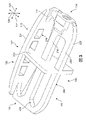
図1および図2は、インプラント100の一実施形態の等角図を示す。具体的には、図1は、インプラント100の上部または上側の等角図であるのに対し、図2は、インプラント100の底部または下側の等角図である。インプラント100は、ケージまたは固定デバイスともいわれることがある。
Implant Overview FIGS. 1 and 2 show isometric views of one embodiment of an
いくつかの実施形態において、インプラント100は、人体の一部に埋め込まれるように構成されている。いくつかの実施形態において、インプラント100は、脊椎に埋め込むように構成されてもよい。いくつかの実施形態では、インプラント100は、隣接する椎骨間に挿入して、椎骨間の支持を提供しおよび/または固定を助ける脊椎固定インプラントまたは脊椎固定デバイスであってもよい。
In some embodiments,
いくつかの実施形態では、インプラント100は、本体部102を含んでもよい。本体部102は、大略的に、インプラント100のフレームまたは骨格を提供してもよい。いくつかの実施形態では、インプラント100は、複数の構造部材104も含んでもよい。複数の構造部材104は、本体部102に装着されてもよく、および/または、本体部102と連続して形成され(もしくは「一体的に形成され」)てもよい。
In some embodiments,
本明細書において用いられる場合、各構造部材は、インプラントの一部に架け渡される特徴的な部材または要素を備える。構造部材は、格子または他の3Dメッシュ構造の要素と同様に、重なってもよく、または交差してもよい。いくつかの実施形態は、部材の長さがその幅およびその厚さよりも大きい構造部材を使用してもよい。構造部材がほぼ円形の断面形状を有する実施形態では、構造部材は、その直径よりも大きい長さを有する。 As used herein, each structural member comprises a distinctive member or element that spans a portion of the implant. Structural members may overlap or intersect, similar to elements of a lattice or other 3D mesh structure. Some embodiments may use structural members where the length of the member is greater than its width and its thickness. In embodiments in which the structural member has a generally circular cross-sectional shape, the structural member has a length greater than its diameter.
図1~図2に示される実施形態では、各構造部材は、ほぼ丸い形または円形の断面形状を有することが分かる(すなわち、部材は中実管の幾何学形状を有する)。しかし、他の実施形態では、構造部材は、種々の多角形断面形状、ならびに任意の他の規則的なおよび/または不規則な断面形状を含むがこれだけに限定されない、任意の他の断面形状を有することができるであろう。ある場合には、たとえば、構造部材の断面形状は、その長さに沿って変えることができるであろう(たとえば、直径がその長さに沿って変化することができるであろう)。 1-2, it can be seen that each structural member has a generally round or circular cross-sectional shape (ie, the member has the geometry of a solid tube). However, in other embodiments, the structural member has any other cross-sectional shape, including, but not limited to, various polygonal cross-sectional shapes, and any other regular and/or irregular cross-sectional shape. could have. In some cases, for example, the cross-sectional shape of the structural member could vary along its length (eg, the diameter could vary along its length).
明確にするために、詳細な説明および特許請求の範囲において方向を示す種々の形容詞に言及する。本明細書において用いられる場合、「前方」という用語は、インプラントを体内に置いたときに人体の前面の方に向けられることが意図される、インプラントの側部または部分を指す。同様に、「後方」という用語は、埋め込み後に人体の背面の方に向けられることが意図される、インプラントの側部または部分を指す。また、「上側」という用語は、体の上部(例、頭)の方に向けられることが意図されるインプラントの側部または部分を指すのに対し、「下側」は、体の底部の方に向けられることが意図されるインプラントの側部または部分を指す。本明細書において、インプラントの「外側」側部または部分にも言及し、これは、体の外側方向に面する側部または部分である(患者の左右の側部に対応する)。 For clarity, various directional adjectives are referred to in the detailed description and claims. As used herein, the term "anterior" refers to the side or portion of the implant that is intended to be oriented toward the front of the human body when the implant is placed in the body. Similarly, the term "posterior" refers to the side or portion of the implant that is intended to be directed toward the back of the human body after implantation. Also, the term "superior" refers to the side or portion of the implant that is intended to be directed toward the upper part of the body (e.g., the head), whereas "inferior" refers to the lower part of the body. Refers to the side or portion of the implant that is intended to be directed toward. Also referred to herein are the "outer" sides or portions of the implant, which are the sides or portions that face outwardly of the body (corresponding to the patient's left and right sides).
図1~図2において、インプラント100は、前方側部110および後方側部112を備えて構成されることが理解される。インプラント100は、インプラント100の両側において後方側部112と前方側部110との間に延びている、第1外側側部114および第2外側側部116を含んでもよい。さらに、インプラント100は、上側側部130および下側側部140を含んでもよい。
1-2, the
また、方向または軸の言及は、体に対してそれが意図される向きではなく、インプラント自体に対するものを指す。たとえば、「遠位」という用語は、インプラントの中心から遠くの方に位置付けられる部分を指すのに対し、「近位」という用語は、インプラントの中心の近くの方に位置付けられる部分を指す。本明細書において用いられる場合、「インプラントの中心」とは、質量の中心、および/または中心面、および/または中心に位置付けられる別の基準面、とすることができるであろう。 Also, references to direction or axis refer to the implant itself, rather than its intended orientation relative to the body. For example, the term "distal" refers to a portion located further from the center of the implant, while the term "proximal" refers to a portion located closer to the center of the implant. As used herein, the "center of the implant" could be the center of mass and/or the center plane and/or another reference plane located at the center.
インプラントは、種々の軸にも関連付けられていてもよい。図1を参照すると、インプラント100は、インプラント100の最長寸法に沿って、第1外側側部114と第2外側側部116との間に延びている長手軸120に関連付けられていてもよい。さらに、インプラント100は、インプラント100の幅寸法に沿って、後方側部112と前方側部110との間に延びている前後軸122(「幅方向軸」ともいう)に関連付けられていてもよい。さらに、インプラント100は、インプラント100の厚さ寸法に沿って延びているとともに長手軸120および前後軸122のどちらに対しても略垂直な、垂直軸124に関連付けられていてもよい。
Implants may also be associated with different axes. Referring to FIG. 1,
インプラントは、種々の基準面または基準表面にも関連付けられていてもよい。本明細書において用いられる場合、「正中面」という用語は、インプラントを右側半体および左側半体に分ける、または2つの外側半体に分ける、インプラントの前方側部から後方側部に通る垂直面を指す。本明細書において用いられる場合、「横断面」という用語は、インプラントを上側半体および下側半体に分ける、インプラントの中心に位置付けられる水平面を指す。本明細書において用いられる場合、「冠状面」という用語は、インプラントを前方半体および後方半体に分ける、インプラントの中心に位置付けられる垂直面を指す。いくつかの実施形態では、インプラントは、正中面および横断面等の2つの平面を中心に対称である。 Implants may also be associated with various reference planes or surfaces. As used herein, the term "median plane" means a vertical plane running from the anterior side to the posterior side of the implant that divides the implant into right and left halves, or divides it into two lateral halves. point to As used herein, the term "transverse plane" refers to a horizontal plane located in the center of the implant that divides the implant into upper and lower halves. As used herein, the term "coronary plane" refers to a vertical plane located in the center of the implant that divides the implant into anterior and posterior halves. In some embodiments, the implant is symmetrical about two planes, such as the median plane and the transverse plane.
本体部
図3および図4は、明確にするために複数の構造部材104を取り除いた、本体部102単体の模式的な等角図を示す。いくつかの実施形態では、本体部は、異なる方向に向けられる別々のフレーム部を含むことができるであろう。図3~図4に示される実施形態では、本体部102はベースフレーム部200を含み、これは、単に「基部200」ともいう。いくつかの実施形態では、基部200は、インプラント100の長手軸120に整列している最長寸法と、前後軸122に整列している幅方向寸法(たとえば、2番目に長い寸法)とを有する。また、いくつかの実施形態では、基部200は、比較的平らで、インプラント100の横断面に平行であることを特徴としてもよい。いくつかの実施形態では、基部200は、上側側部130と下側側部140との間のほぼ真ん中(たとえば、垂直軸124に対してインプラント100の中央)に位置付けられてもよく、したがって、インプラント100の横断面に一致してもよい。しかし、他の実施形態では、基部200は、上側側部140よりも上側側部130の近くに、またはその逆に、配設することができるであろう。
Body Portion FIGS. 3 and 4 show schematic isometric views of the
図3~図4に示される実施形態では、本体部102は、ここでは中央竜骨部(central keel portion)202という、垂直向きフレーム部も含む。いくつかの実施形態では、中央竜骨部202は、その最長の寸法を前後軸122およびその幅に沿って方向付けされていてもよく、または2番目に長い寸法を垂直軸124に沿って方向付けされていてもよい。また、ある場合には、中央竜骨部202は、第1外側側部114と第2外側側部116との間のほぼ真ん中(たとえば、長手軸120に対してインプラント100の中央)に位置付けてもよく、したがって、インプラント100の正中面と一致してもよい。しかし、他の実施形態では、中央竜骨部202は、第2外側側部116よりも第1外側側部114の近くに、またはその逆に、配設することができるであろう。
In the embodiment shown in FIGS. 3-4, the
いくつかの実施形態では、インプラントの1つまたは複数の側部(外側側部および/または前方/後方側部を含む)は、周辺フレーム部を含むことができるであろう。図3~図4の実施形態では、本体部102は、後方側部112に配設されている周辺フレーム部204を含むことが分かり、これは、インプラント100の「後方壁」といわれることもある。周辺フレーム部204は、基部200から垂直に延びていることが分かる。対して、図3~図4の実施形態では、前方側部110には、基部200の厚みを越えて垂直に延びているフレーム部または壁はない。フレーム部204の存在が、脊椎の後方側部に沿ってかかる垂直荷重に対する、支持および強度を改善してもよい。
In some embodiments, one or more sides of the implant (including lateral sides and/or anterior/posterior sides) could include a peripheral frame portion. In the embodiment of FIGS. 3-4, the
本実施形態は、インプラント100の後方側部に垂直向きフレームまたは壁を使用するが、他の実施形態では、垂直向きフレームまたは壁は、インプラント100の前方側部に位置付けることができるであろう。このような代替構成を以下に述べ、図13~図15に示す。さらに他の実施形態では、インプラントには、その周囲に沿って(すなわち、後方側部、前方側部、または外側側部に沿って)垂直壁が一切なくてもよい。
Although this embodiment uses a vertically oriented frame or wall on the posterior side of the
一般的に、本体部の1つまたは複数のフレーム部(たとえば、基部200、中央竜骨部202およびフレーム部204)の幾何学形状は、実施形態によって変えることができるであろう。たとえば、フレーム部は、インプラント100を貫いて骨成長を促す可能性のある、および/または重量を減らす可能性のある、1つまたは複数の窓、スロットおよび/または開口を含むことができる。いくつかの実施形態では、1つまたは複数のフレーム部の開口は、インプラント100の内部領域へのアクセスを改良し、そのことが、以下でさらに詳細に述べるように、骨成長促進材料(BGPM)の挿入を容易にしてもよい。
In general, the geometry of one or more frame portions (eg,
図3~図4の実施形態では、基部200は、中実の外周225から構成されてもよい。さらに、基部200は、基部200を後方セグメント232、前方セグメント234および中央セグメント236に分ける複数のスロット230を含んでもよい。
図3~図4の実施形態では、各セグメントは、中央竜骨部202と交差している。また、中央竜骨部202は、スロット230を、中央竜骨部202によって長手方向に分離される1対のスロットにさらに分割してもよい。しかし、他の実施形態では、スロット230は、中央竜骨部202を通り抜けて延びることができるであろう。
In the embodiment of FIGS. 3-4, the
In the embodiment of FIGS. 3-4, each segment intersects the
いくつかの実施形態では、中央竜骨部202は、開口を含んでもよい。他の実施形態では、中央竜骨部202は、開口のない中実のフレームを備えることができるであろう。いくつかの実施形態では、開口を設けることで、インプラント100の内部の相対する外側側部間に骨成長が起こることを許容してもよい。
In some embodiments, the
いくつかの実施形態では、フレーム部204は、開口を含むことができるであろう。他の実施形態では、フレーム部204は、開口を含まなくてもよい。いくつかの実施形態では、フレーム部の開口は、骨移植片材料またはBGPMをインプラントの内部に挿入するためのアクセス点を提供することができるであろう。フレーム部204の開口の数、サイズおよび/または形状は変えることができるであろう。ある場合には、3つ以上の開口を使用することができるであろう。他の場合には、2つの開口を使用することができるであろう。さらに他の場合には、単一の開口を使用することができるであろう。使用することができるであろう開口の例示的な形状は、丸い開口、矩形開口、多角形開口、規則形の開口および/または不規則形の開口を含むが、これだけに限定されない。
In some embodiments,
図3~図4の実施形態では、フレーム部204は、4つの矩形開口249を含む。図14に示すさらに別の実施形態では、フレーム部704は、2つの大きな楕円形の窓(すなわち、第1窓757および第2窓759)を含み、骨移植片材料(またはBGMP)をインプラントの内部に挿入しやすくしてもよい。
In the embodiment of FIGS. 3-4,
いくつかの実施形態では、インプラントの挿入および/または固定を含めて埋め込みを容易にする手段を含むことができる。いくつかの実施形態は、留め具受け部を含むことができる。 Some embodiments may include means to facilitate implantation, including insertion and/or fixation of the implant. Some embodiments can include fastener receivers.
たとえば、図4でもっともよく分かるように、インプラント100は、留め具受け部238を含む。留め具受け部238は、ねじ切り開口239と、ねじ切り開口239を支持する補強カラー237とを含む。いくつかの実施形態では、ねじ切り開口239は、インプラント100の埋め込みを容易にするために、対応するねじ切り先端をもつツールを受け入れるように構成されてもよい。いくつかの実施形態では、ねじ切り開口239は、ねじとともに使用して、インプラント100を骨または他の固定デバイスに装着するのを助けてもよい。他の実施形態では、留め具および/または埋め込みツールを受け入れるための任意の他の特徴をインプラント100に組み込むことができるであろう。
For example, as best seen in FIG. 4,
構造部材
インプラントは、2つ以上の種類の構造部材を含んでもよい。いくつかの実施形態では、インプラントは、1つまたは複数の外方構造部材、または単に「外方部材」を含むことができる。外方部材は、一般に、インプラントの上下側部に沿ってなど、インプラントの外面に完全に露出していてもよい。外方部材は、埋め込み後に椎骨に接触する、骨接触部材として構成されてもよい。しかし、他の実施形態では、1つまたは複数の外方部材のうちのいくつかの部分は、インプラントの外面に沿って別の要素によって隠すかまたは被覆することができるであろう。
Structural Members Implants may include more than one type of structural member. In some embodiments, an implant can include one or more outer structural members, or simply "outer members." The outer member may generally be completely exposed on the outer surface of the implant, such as along the superior and inferior sides of the implant. The outer member may be configured as a bone contacting member that contacts the vertebrae after implantation. However, in other embodiments some portions of the one or more outer members could be hidden or covered by another element along the outer surface of the implant.
いくつかの実施形態では、インプラントは、1つまたは複数の外方部材に支持を提供する1つまたは複数の構造部材を含むことができる。このような支持用の構造部材は、「支持部材」といわれることもある。いくつかの実施形態では、各支持部材の少なくともいくつかの部分は、インプラントの外方部材または別の要素によって隠してもよく、または被覆してもよい。このように、支持部材は、大略的にインプラントの内部の中に配設される「内方部材」と見なしてもよく、内部は、本体部と外方部材とによって境界付けられていてもよい。 In some embodiments, an implant can include one or more structural members that provide support to one or more outer members. Such supporting structural members are sometimes referred to as "support members." In some embodiments, at least some portion of each support member may be hidden or covered by an outer member or another element of the implant. As such, the support member may be viewed generally as an "inner member" disposed within the interior of the implant, the interior may be bounded by the body portion and the outer member. .
図5および図6は、実施形態による、インプラント100の模式的な等角図を示す。図5~図6で分かるように、インプラント100は、複数の外方部材180および複数の支持部材182を含んでもよい。外方部材180は、図5ではっきりと見ることができ、図5では、支持部材182の一部を仮想線で描いて、外方部材をより明確に詳述している。同様に、支持部材182は、図6ではっきりと見ることができ、図6では、外方部材180の一部を仮想線で描いて、支持部材をより明確に詳述している。
5 and 6 show schematic isometric views of
いくつかの実施形態では、外方部材は、内方部材の遠位に配設され、外方部材は、大略的にインプラントの上下側部に沿ってさらに外向きに配設されている。したがって、外方部材は、脊椎への埋め込み後、大略的に椎体終板のより近くに配設されてもよい。さらに、外方部材が内方部材に装着されている領域では、外方部材の装着部は、内方部材の装着部の遠位に配設されてもよい。 In some embodiments, the outer member is disposed distal to the inner member and the outer member is disposed generally further outward along the superior and inferior sides of the implant. Thus, the outer member may be disposed generally closer to the vertebral body endplates after implantation into the spine. Further, in regions where the outer member is attached to the inner member, the attachment portion of the outer member may be disposed distal to the attachment portion of the inner member.
一実施例として、図7は、インプラント100の模式的な等角図を示し、外方部材370と支持部材390との間の装着領域189の拡大断面図を含む。ここでは、外方部材370は、支持部材390の上に広がっていることが分かる。また、外方部材370は、支持部材390の遠位に位置付けられていることが分かる。ここでは、遠位とは、インプラント100の基部200または横断面から遠くに配設されることを意味することが意図される。
As an example, FIG. 7 shows a schematic isometric view of
図1~図2でもっともよく分かるように、複数の構造部材104は、基部200または中央竜骨部202のいずれかによって分離されている4つの別々のセットとして配置されてもよい。具体的には、複数の構造部材104は、構造部材の第1のセット260と、構造部材の第2のセット262と、構造部材の第3のセット264と、構造部材の第4のセット266とを含む。各セットは、外方部材と支持部材との両方を含み、各セットの部材は、インプラント100のそれぞれの象限において、基部200、中央竜骨部202および/またはフレーム部204に装着されている。
As best seen in FIGS. 1-2, the plurality of
構造部材の、本体部への装着
以下の説明は、主に構造部材の第1のセット260に関するものであるが、ここで述べる特定の構造部材の同様な性質および原理は、構造部材の残りのセットの1つにも適用してもよいことは認識されよう。
Attaching the Structural Members to the Body Although the following description is primarily directed to the
いくつかの実施形態では、1つまたは複数の構造部材は、端部のない閉ループとすることができる。他の実施形態では、少なくともいくつかの構造部材は、2つの端部を備える。ある場合には、2つの端部を有する構造部材は、別の構造部材に装着される1つまたは複数の端部を含むことができるであろう。他の場合には、2つの端部を有する構造部材は、両端部がインプラントの本体部の一部に装着されるように配置することができるであろう。図5~図6に図示する実施形態では、各構造部材は、2つの端部を含み、各端部は、インプラント100の本体部102の何らかの部分に装着されている。
In some embodiments, one or more structural members can be closed loops without ends. In other embodiments, at least some of the structural members have two ends. In some cases, a structural member having two ends could include one or more ends attached to another structural member. In other cases, a structural member having two ends could be arranged such that both ends are attached to a portion of the body of the implant. In the embodiment illustrated in FIGS. 5-6, each structural member includes two ends, each attached to some portion of
いくつかの実施形態において、インプラントは、一端部が基部に装着されて他端部が中央竜骨部に装着されている、少なくとも1つの外方部材を含んでもよい。たとえば、図5で分かるように、外方部材300は、中央竜骨部202に装着されている第1端部302と、基部200に装着されている第2端部304とを含む。
In some embodiments, the implant may include at least one outer member having one end attached to the base and the other end attached to the central keel. For example, as seen in FIG. 5,
いくつかの実施形態では、インプラントは、一端部がフレーム部(または側壁)に装着されて他端部が中央竜骨部に装着されている、少なくとも1つの外方部材を含んでもよい。たとえば、図5で分かるように、外方部材310は、中央竜骨部202に装着されている第1端部312と、フレーム部204に装着されている第2端部314とを含む。
In some embodiments, the implant may include at least one outer member having one end attached to the frame portion (or sidewall) and the other end attached to the central keel portion. For example, as seen in FIG. 5,
いくつかの実施形態では、インプラントは、2つの端部がインプラントの基部に装着されている少なくとも1つの外方部材を含んでもよい。たとえば、図5で分かるように、外方部材320は、基部200の第1部分332に装着されている第1端部322を含むとともに、外方部材320は、基部200の第2部分334に装着されている第2端部324を含む。
In some embodiments, the implant may include at least one outer member having two ends attached to the base of the implant. For example, as seen in FIG. 5,
異なる実施形態では、支持部材は、本体部の異なる部分に装着することができるであろう。いくつかの実施形態では、支持部材の1つまたは複数の端部は、基部に装着することができるであろう。他の実施形態では、支持部材の1つまたは複数の端部は、中央竜骨部に装着することができるであろう。さらに他の実施形態では、支持部材の1つまたは複数の端部は、前方または後方のフレーム部に装着することができるであろう。 In different embodiments, the support member could be attached to different portions of the body. In some embodiments, one or more ends of the support member could be attached to the base. In other embodiments, one or more ends of the support member could be attached to the central keel. In still other embodiments, one or more ends of the support member could be attached to the front or rear frame portion.
図6の実施形態では、支持部材の多くは、両端部で基部200に装着されている。たとえば、支持部材340は、基部200に装着されている第1端部342と、基部200に装着されている第2端部344とを含む。他の支持部材も、一端部がフレーム部204に装着されている。たとえば、支持部材350は、基部200に装着されている第1端部352と、フレーム部204に装着されている第2端部354とを含む。
In the embodiment of FIG. 6, many of the support members are attached to base 200 at both ends. For example,
ここで説明する、外方部材と支持部材とを本体部に装着するための特定の配置が、インプラントの有用性および強度を改善してもよい。具体的には、いくつかの外方部材の一端部を中央竜骨部またはサイドフレーム部のいずれかに取り付けることにより、癒合のために隣接する椎骨に露出する外方部材の総表面積を最大化することができる。さらに、支持部材の少なくともいくつかの両端部を本体部に装着することにより、外方部材の荷重支持サポートを改善するように、支持部材は、長さを短くし、アーチ状にしてもよい。 Certain arrangements for mounting the outer member and support member to the body described herein may improve the usefulness and strength of the implant. Specifically, attaching one end of several outer members to either the central keel portion or the side frame portion maximizes the total surface area of the outer members exposed to the adjacent vertebrae for fusion. be able to. Further, the support members may be shortened in length and arcuate so as to improve the load-bearing support of the outer member by attaching at least some of the ends of the support members to the body.
本体部に対する構造部材の配置は、所望の総開放容量を実現するように設計してもよい。本明細書で用いられる場合、総容量とは、構造部材間の任意の開口、本体部内の任意の開口、構造部材と本体部との間の開口を合算した容量である。この開放構成は、インプラント内で、およびインプラントを貫いて、骨成長を促す。開放スペースの一部または全部は、任意選択的に、骨成長を促すために、インプラントの挿入前または挿入後に、骨移植片または骨成長促進材料で埋められる。 The arrangement of structural members relative to the body may be designed to achieve the desired total open volume. As used herein, total volume is the combined volume of any openings between structural members, any openings within the body, and openings between the structural members and the body. This open configuration encourages bone growth within and through the implant. Some or all of the open space is optionally filled with bone graft or bone growth promoting material before or after insertion of the implant to encourage bone growth.
任意の特定のインプラント内の開放スペースの総容量(単に開放スペース容量ともいう)は、インプラントの全体的な寸法、ならびに、構造部材、フレーム部等を含めたインプラント内の個々の構成要素のサイズおよび寸法に左右される。開放スペース容量は、インプラントの容量の約20%~80%の範囲としてもよい。いくつかの実施形態では、インプラント100は、インプラントの総容量の25%~80%の開放スペース容量を有してもよい。さらに別の実施形態では、インプラント100は、インプラント総容量の40%~75%の開放スペース容量を有してもよい。
The total volume of open space within any particular implant (also referred to simply as open space volume) is a function of the overall dimensions of the implant as well as the size and size of individual components within the implant, including structural members, frames, etc. Dimensions dependent. The open space volume may range from about 20% to 80% of the volume of the implant. In some embodiments,
全体的な対称性
いくつかの実施形態では、インプラントは、1つまたは複数の対称性をもって構成することができる。ある場合には、インプラントは、1つまたは複数の基準面に対して鏡面対称性を有してもよい。他の場合には、インプラントは、1つまたは複数の基準面に対して並進対称性を有してもよい。さらに他の場合には、インプラントは、鏡面対称性および並進対称性の両方を有することができるであろう。
Overall Symmetry In some embodiments, implants can be configured with one or more symmetries. In some cases, an implant may have mirror symmetry with respect to one or more reference planes. In other cases, the implant may have translational symmetry with respect to one or more reference planes. In still other cases, the implant could have both mirror and translational symmetry.
図1および図2を参照すると、インプラント100は、少なくとも1つの鏡面対称性を含んでもよい。参照のために、インプラント100は、上側半体および下側半体に分割してもよい。ここでは、インプラント100の「上側半体」は、横断面よりも上に配設されている本体部102および複数の構造部材104の部分を含む。同様に、インプラント100の「下側半体」は、横断面より下に配設されている本体部102および複数の構造部材104の部分を含む。
1 and 2,
横断面(これは、本実施形態において基部200と大略的に一致している)に対して、インプラント100の上側半体は、インプラント100の下側半体を鏡像にしていることが分かるだろう。これには、本体部の幾何学形状だけでなく、各構造部材の形状、サイズおよび向きも含まれる。この鏡面対称性は、いくつかの実施形態では近似しているだけでもよいことは認識されよう。
It will be seen that the upper half of the
参照のために、インプラント100は、第1外側半体および第2外側半体に分割されてもよい。図1~図2を参照すると、「第1外側半体」は、第1外側縁270と中央竜骨部202との間に配設されているインプラント100の部分を含むのに対し、「第2外側半体」は、第2外側縁272と中央竜骨部202との間に配設されているインプラント100の部分を含む。
For reference,
図1~図2に示す実施形態で、第1外側半体の構造部材104の構成は、第2外側半体の構造部材104の構成とほぼ同様であることが観察されよう。より具体的には、構造部材104のパターンは、第1外側半体および第2外側半体を通して反復している。構造部材のパターンとは対照的に、下に横たわる基部200の幾何学形状は、繰り返し構成というよりも、中央竜骨部202に対して鏡面対称である。
It will be observed that in the embodiment shown in FIGS. 1-2, the configuration of the
外方部材のらせん形幾何学形状
実施形態では、インプラントの外方部材に沿った、また、インプラントに隣接した、骨成長を保護するための手段を含むことができる。いくつかの実施形態では、外方部材は、選択された領域または「保護された癒合領域」における新たな骨成長の保護を助ける幾何学形状で構成することができる。いくつかの実施形態では、外方部材は、骨成長を促進するために一連のそうした保護された癒合領域を提供する、渦巻き形、らせん形または捻れた幾何学形状を有することができる。
Helical Geometry of Outer Member Embodiments can include means for protecting bone growth along and adjacent to the outer member of the implant. In some embodiments, the outer member can be configured with a geometry that helps protect new bone growth in selected areas or "protected fusion areas." In some embodiments, the outer member can have a spiral, helical or twisted geometry that provides a series of such protected fusion areas to promote bone growth.
いくつかの外方部材は、一般的ならせん形幾何学形状を有してもよい。本明細書で用いられる場合、「一般的ならせん形幾何学形状」または「渦巻き幾何学形状」とは、ある部品(部分、部材、等)が固定経路の周りに巻かれるか、その周りで向きを変えるか、捻れるか、回転するか、またはその他の形で湾曲されている幾何学形状をいう。ある場合には、固定経路は、直線とすることができるであろう。他の場合には、固定経路は、湾曲することができる。本実施形態では、たとえば、固定経路は、大略的に直線セグメントと湾曲セグメントとの組み合わせである。 Some outer members may have a general helical geometry. As used herein, "general helical geometry" or "spiral geometry" means that a part (part, member, etc.) is wound about or spirals around a fixed path. A geometric shape that turns, twists, rotates, or is otherwise curved. In some cases, the fixed path could be straight. In other cases, the fixation path can be curved. In this embodiment, for example, the fixed path is generally a combination of straight and curved segments.
図8は、一般的ならせん形幾何学形状をもつ湾曲部400の模式図を示す。湾曲部400は、それ自体が湾曲している固定経路402の周りに巻かれていることが分かる。しかし、湾曲部400とは対照的に、固定経路402は、巻き、巻回等を含んでいない。直線形の固定経路をもつらせん形湾曲部の実施例が、コイル状インプラント出願の図1に示されている。
FIG. 8 shows a schematic diagram of a
一般的ならせん形幾何学形状を有する湾曲部(一般的ならせん形湾曲部ともいう)は、固定経路を中心とした「コイル」、「巻き」または「巻回」によって特徴付けてもよい。一般的ならせん形湾曲部の特定の幾何学形状を特徴付けてもよい例示的なパラメータは、コイルの直径(長径および短径の両方を含む)およびピッチ(すなわち、隣接するコイル間の間隔)を含むことができる。ある場合には、コイルまたはループの「振幅」も、コイルまたはループの直径または幅方向の寸法を記述するために使用してもよい。これらのパラメータのそれぞれは、定数とすること、または一般的ならせん形湾曲部の長さにわたって変えることができるであろう。 A bend having a general helical geometry (also referred to as a general helical bend) may be characterized by a "coil", "turn" or "turn" about a fixed path. Exemplary parameters that may characterize a particular geometry of a typical helical bend are coil diameter (including both major and minor diameters) and pitch (i.e., spacing between adjacent coils). can include In some cases, the "amplitude" of a coil or loop may also be used to describe the diameter or width dimension of the coil or loop. Each of these parameters could be constant or varied over the length of the typical helical bend.
一般的ならせん形湾曲部は、円形である必要も、または丸みを帯びている必要さえもない。いくつかの実施形態では、たとえば、一般的ならせん形湾曲部は、各「コイル」または「巻き」が、円弧または他の湾曲セグメントではなく直線セグメントから構成されるように、直線状に分割された形状(または局所的に多角形形状)を有することができるであろう。このような一般的ならせん形湾曲部の実施例を図9に示す。図9を参照すると、一般的ならせん形湾曲部420は、直線セグメント422から構成されていることが分かる。隣接するセグメント間の角度は、「多角形コイル」において固定経路424の周りに巻かれるかまたはその周りで輪にされるようにされている。
A typical helical bend need not be circular or even rounded. In some embodiments, for example, a typical helical bend is split linearly such that each "coil" or "turn" is composed of straight segments rather than arcs or other curved segments. could have a square shape (or locally polygonal shape). An example of such a typical helical bend is shown in FIG. Referring to FIG. 9, it can be seen that a typical
一般的ならせん形湾曲部は、湾曲セグメントと直線セグメントとの組み合わせも含んでもよい。このような組み合わせ湾曲部の実施例を図10に図示する。図10を参照すると、一般的ならせん形湾曲部440は、固定経路444の周りに硬化した略丸い(すなわち、湾曲した)コイルセグメント442を含む。さらに、湾曲部440は、隣接するコイル間に延びている少なくとも1つの直線セグメントを含む。
A typical helical bend may also include a combination of curved and straight segments. An example of such a combination curve is illustrated in FIG. Referring to FIG. 10, a typical
図8から図10に示す一般的な湾曲部は、一次元の湾曲部であるが、同様な原理は、構造部材を含めた三次元部品にも適用してもよい。 Although the typical bends shown in FIGS. 8-10 are one-dimensional bends, similar principles may be applied to three-dimensional parts, including structural members.
1つまたは複数の構造部材の幾何学形状を特徴付けるために、各構造部材は、「湾曲中央部」を有すると理解することができる。各構造部材の湾曲中央部は、湾曲部に沿った各点が構造部材内の中央に位置付けられるように、構造部材の長さに沿って延びている湾曲部として定義されてもよい。 To characterize the geometry of one or more structural members, each structural member may be understood to have a "curved central portion." A curved central portion of each structural member may be defined as a curved portion extending along the length of the structural member such that each point along the curved portion is centrally located within the structural member.
構造部材が、構造部材自体の断面径よりもはるかに大きい振幅または直径、固定経路の周りに巻かれるかまたはその周りで輪にされている実施形態では、見て分かるはっきりしたコイルとなるように構造部材を巻いてもよい。このようなコイルは、コイル状インプラント出願で完全に詳細に述べられている。しかし、他の実施形態では、構造部材は、構造部材自体の断面径よりも小さい振幅または直径で、固定経路の周りに巻くことができるであろう。このような場合、得られる構造部材の幾何学形状は捻れたように見えるかもしれないが、幾何学形状には、コイル状インプラント出願に見られるはっきりしたコイルはないかもしれない。しかし、このような構造部材の最外層がはっきりしたコイルを呈さない可能性がある一方で、構造部材の湾曲中央部はそのようなコイルまたは巻きを有し、また、明確な一般的ならせん形幾何学形状を有することは認識されよう。 In embodiments where the structural member is wrapped around or looped around a fixed path of amplitude or diameter much larger than the cross-sectional diameter of the structural member itself, so as to be a distinct coil visible. Structural members may be rolled. Such coils are described in full detail in the Coiled Implant Application. However, in other embodiments, the structural member could be wrapped around the fixed path with an amplitude or diameter smaller than the cross-sectional diameter of the structural member itself. In such cases, the geometry of the resulting structural member may appear twisted, but the geometry may not have the distinct coils found in coiled implant applications. However, while the outermost layers of such structural members may not exhibit distinct coils, the curved central portion of the structural member may have such coils or turns and may also have a distinct general helical shape. It will be appreciated that it has a geometric shape.
図11は、単一の外方部材300が示されている、インプラント100の模式的な等角図である。ここでは、2つの支持部材も見える。残りの構造部材は、明確にするために、図11から取り除いてある。図12は、明確にするためにすべての構造部材を取り除いた、本体部102の模式的な等角図である。
FIG. 11 is a schematic isometric view of
図11で分かるように、外方部材300の外面は、渦巻き形またはらせん形を示す捻れた幾何学形状を呈する。しかし、外方部材300の厚みよりもはるかに小さい振幅で巻回が生じているため、この部分の幾何学形状は判別しにくい可能性がある。外方部材300の一般的ならせん形幾何学形状は、その湾曲中央部(central member curve)502の幾何学形状(図12ではっきりと分かる)が固定経路540(同じく図12に示す)の周りに巻かれていると考えられるときに、はるかに明確になる。
As can be seen in FIG. 11, the outer surface of
外方部材300の巻回幾何学形状を図示するために、図11は、外方部材300に沿って切断した一連の断面図を含む。第1部分510の第1断面図では、湾曲中央部502の第1地点(図11では十字印を用いて示す)は、固定経路540の対応する地点(丸印で示す)とほぼ整列していることが分かる。第2部分512で、湾曲中央部502の第2地点は、固定経路540の対応する地点から離れた第1回転位置に位置付けられていることが分かる。第3部分514では、湾曲中央部502の第3地点は、固定経路540の対応する地点から第2の回転位置に位置付けられていることが分かる。このように、外方部材300がその延長に沿って基部200と中央竜骨部202との間を小さな振幅で捻れると、湾曲中央部502は、実際に固定経路540の周りに巻かれるかまた固定経路540の周りでらせん形に走行することが分かる。ここでは、固定経路540は、外方部材300の「平均」または近似の経路を表しており、いくつかのセグメントにおけるらせん形の脱線を無視していることは理解されよう。
To illustrate the winding geometry of
図11と図12とを比べてはっきりと分かるように、外方部材300の断面径550は、湾曲中央部502のコイルまたは巻きの対応する巻径552よりも大きい。他の実施形態では、外方部材の断面径は、その湾曲中央部のコイルまたは巻きの対応する巻径よりも小さくすることができるであろう。このような実施形態では、外方部材は、一連のはっきりしたコイル状に構成されるであろう。
As can be clearly seen by comparing FIGS. 11 and 12, the
図11および図12を参照すると、外方部材300は、その全長にわたり一般的ならせん形幾何学形状を有していない。代わりに、その湾曲中央部は、湾曲中央部が固定経路の周りを数回ぐるりと巻ききる(図11~図12では3回)巻回セグメントを備えて構成されている。巻回セグメントの他には、その湾曲中央部は、巻き、捻れ等は含まなくてもよい。
11 and 12,
本実施形態は、固定経路の周りを1回または複数回ぐるりと巻く巻回セグメントを備える少なくとも1つの外方部材を含むが、他の実施形態は、固定経路の周りで部分的にしか輪をなさない湾曲中央部を備えて構成することができるであろう。 While this embodiment includes at least one outer member comprising a winding segment that wraps around the fixed path one or more times, other embodiments only partially loop around the fixed path. It could be configured with a curved midsection that does not form.
ここでの説明は、単一の外方部材300の幾何学形状を中心に行ってきたが、複数の構造部材104の残りの外方部材の一部または全部が同様な一般的ならせん形幾何学形状を有してもよいことは認識されよう。さらに、2つの異なる外方部材が、巻き数、巻回の形状等の変型を含むはっきりした外方部材湾曲部をもつ、わずかに異なる幾何学形状を有することができることが認識されよう。
Although the discussion herein has focused on the geometry of a single
いくつかの実施形態では、インプラントは、インプラントの長さ、幅または高さと比べて小さい距離に局所的にらせん形である外方部材を含むことができる。たとえば、インプラント100は、全体的にらせん形なのではなく、局所的にらせん形または局所的に渦巻きである外方部材を有することを特徴としてもよい。特に、インプラント100の各外方部材は、インプラント100の単一の象限内に限られ、インプラント100の横断面または正中面と交差しない。このように、外方部材がぐるりとひと巻きすることは、インプラントの長さ、幅または高さの半分よりもはるかに小さい距離で達成される。これにより、インプラントの各象限内に複数の巻回が可能になり、巻回間のピッチも、インプラントの長さ、幅または高さよりも小さくなる。
In some embodiments, the implant can include an outer member that is locally helical over a distance that is small compared to the length, width or height of the implant. For example,
たとえば、図12では、湾曲中央部502は、外方部材300の長さの3/1よりも小さい、隣接する巻回または巻き間のピッチ529を有する。また、ピッチ529は、インプラント100の長さの10/1よりも小さい。この比較的小さなピッチサイズは、各外方部材に沿って近位表面領域の数を増やすことを可能にし、それにより、インプラント100の下側表面および上側表面で利用できる保護された癒合領域の数が増える。
For example, in FIG. 12, curved
いくつかの実施形態では、外方部材のらせん状幾何学形状は、インプラントの上側側部および下側側部に露出されるはっきりした領域を提供する。たとえば、再び図7を参照すると、各外方部材は1つまたは複数の遠位領域360を含み、これが、インプラント100の上側側部130に沿った外方部材の「頂点」に見えてもよい。少なくともいくつかの実施形態では、これらの遠位領域360は、上側側部130(および下側側部140)上の平らなまたは滑らかな最遠位表面を提供し、それによって隣接する椎骨と接触しやすくするように、平坦化または「平滑化」してもよい。たとえば、インプラントのほぼ滑らかな上側表面および下側表面が分かる、インプラントの別の実施形態を示す図15を参照のこと。他の実施形態では、遠位表面領域は、湾曲していてもよい。ある場合には、遠位表面領域は、外方部材の隣接する表面領域の曲率と一致する曲率を有することができるであろう。他の場合には、遠位表面領域は、外方部材の隣接する表面領域とは異なる曲率(たとえば、さらに凸)を有することができるであろう。
In some embodiments, the helical geometry of the outer member provides distinct areas of exposure on the superior and inferior sides of the implant. For example, referring again to FIG. 7, each outer member includes one or more
外方部材は、インプラント100の上側側部130に沿って、外方部材の「谷」に見える近位領域362も含んでもよい。遠位領域360がインプラント100の埋め込み中およびその後に椎骨と直接接触することになってもよいのに対し、近位領域362は、少なくとも新たな骨成長が生じるまでは、椎骨と直接接触することなく、凹んでいてもまたは離間していてもよい。
The outer member may also include a
特定の実施例として、図7は、外方部材370および下に横たわる支持部材390の一部の拡大断面図を含む。具体的には、外方部材370の外向き表面部372は見えている。本明細書で用いられる場合、外方部材の「外向き表面部」とは、外方部材の表面のうち、埋め込み中に椎骨の方を向く部分、またはインプラントの内部から遠ざかる方を向く部分である。外向き表面部372は、第1遠位表面領域380、近位表面領域382および第2遠位表面領域384を含む。以下でさらに詳細に述べるように、この局所的な幾何学形状は、各近位表面領域に隣接する一連の保護された癒合領域を提供し、ここで、早期の骨癒合中に新たな骨成長を保護することができる。
As a particular example, FIG. 7 includes an enlarged cross-sectional view of a portion of
支持部材のアーチ状幾何学形状
外方部材が一般的ならせん形幾何学形状を有してもよいのに対し、支持部材の幾何学形状は、強度および支持を高めるように選択してもよい。いくつかの実施形態では、支持部材は、略管状(中実)形状を有することができ、本体部のある部分から別の部分まで単純な曲線で延びていてもよい。特に、ある場合には、支持部材の湾曲中央部は、局部的な捻れ、巻回またはコイルなく、滑らかに湾曲していてもよい。
Support Member Arcuate Geometry While the outer member may have a general helical geometry, the support member geometry may be selected to enhance strength and support . In some embodiments, the support member may have a generally tubular (solid) shape and may extend in a simple curve from one portion of the body to another. In particular, in some cases, the curved central portion of the support member may be smoothly curved without local twists, turns or coils.
図11を参照すると、本実施形態の支持部材は、形状が略管状であり、本体部102のある部分から別の部分まで単純な曲線で延びている。たとえば、支持部材600および支持部材602は、いずれも、基部200の前方セグメント234から中央セグメント236までアーチ状の形状で延びている。また、図12で分かるように、これらの支持部材の湾曲中央部606は、固定曲線に対する巻回、コイルまたは捻れを含まない。
Referring to FIG. 11, the support member of this embodiment is generally tubular in shape and extends in a simple curve from one portion of
このように、いくつかの実施形態では、支持部材は、大略的に短くしてもよく、その幾何学形状は、よりアーチ状になるようにして、外方部材について、強度を高めるとともに支持を増大してもよい。対して、外方部材は、椎骨との接触を提供するためにはインプラントの上側/下側側部にできるだけ広く延びている必要があるため、外方部材は、大略的により長い長さを有してもよく、支持部材に対して湾曲を抑えたアーチ状の形状にしてもよい。 Thus, in some embodiments, the support member may be generally shorter and its geometry more arcuate to provide increased strength and support for the outer member. may increase. In contrast, the outer member generally has a longer length because it needs to extend as wide as possible over the upper/lower sides of the implant to provide contact with the vertebrae. Alternatively, the support member may have an arch-like shape with less curvature.
いくつかの実施形態は、一般的ならせん形幾何学形状をもつ外方部材と、アーチ状の幾何学形状をもつ内方支持部材とを含むが、他の実施形態では、任意の構造部材は、任意のタイプの幾何学形状で構成することができるであろう。たとえば、別の実施形態では、1つまたは複数の内方支持部材は、一般的ならせん形幾何学形状を有することができるであろう。さらに別の実施形態では、1つまたは複数の外方部材は、アーチ状の幾何学形状を有することができるであろう。 Some embodiments include an outer member with a general helical geometry and an inner support member with an arcuate geometry, while in other embodiments the optional structural member , could be configured with any type of geometry. For example, in another embodiment, one or more of the inner support members could have a general helical geometry. In yet another embodiment, one or more of the outer members could have an arcuate geometry.
近位領域での支持
異なる実施形態では、支持部材と外方部材との間の装着は、種々の場所で行うことができるであろう。いくつかの実施形態では、支持部材は、外方部材の外面に沿って、遠位表面領域付近に装着することができるであろう。他の実施形態では、支持部材は、外方部材の外面に沿って、近位表面領域付近に装着することができるであろう。
Support at the Proximal Region In different embodiments, the attachment between the support member and the outer member could occur at various locations. In some embodiments, the support member could be attached near the distal surface region along the outer surface of the outer member. In other embodiments, the support member could be attached near the proximal surface region along the outer surface of the outer member.
いくつかの実施形態では、各支持部材は、外方部材の近位表面領域に隣接する(または、その下になる)場所で対応する外方部材に装着するように構成される。たとえば、図11に示すように、支持部材600の装着部610は、外方部材300の近位表面領域620に対応する場所で外方部材300に装着されている。同様に、インプラント100の他のどの支持部材も、近位表面領域に対応する場所でのみ1つまたは複数の外方部材に装着している。
In some embodiments, each support member is configured to attach to a corresponding outer member at a location adjacent to (or underlying) the proximal surface region of the outer member. For example, as shown in FIG. 11,
この構成は、近位領域のすぐ隣のスペースに広がる保護された癒合領域を提供する。保護された癒合領域は、インプラントの上側/下側表面に沿った場所であり、ここでは、隣接する支持部材から、または椎骨から直に外方部材にかかる力から新たな骨成長を部分的に保護することができる。 This configuration provides a protected coaptation area that spans the space immediately adjacent to the proximal region. The protected fusion area is a location along the superior/inferior surface of the implant where new bone growth is partially induced from forces on the outer member from adjacent support members or directly from the vertebrae. can be protected.
1つまたは複数の外方部材を少なくとも1つのらせん形部分を備えて構成することにより、外方部材は、インプラントの上側側部および下側側部に1つまたは複数の保護された癒合領域を提供してもよい。これらの保護された癒合領域は、外方部材の近位領域のすぐ隣のスペースに広がる。近位領域によって提供される凹んだスペースは、遠位領域で生じる可能性がある初期癒合に隣接して、新たな骨成長のためポケットを許容する。また、支持部材は、近位表面領域付近に装着されており、遠位表面領域には装着されていないため、支持部材または椎骨のいずれかによって外方部材にかかる力は、保護された癒合領域から遠ざかる方に向けることができ、それによって、新たな骨成長の乱れ(disturbance)を最小化する。保護された癒合領域内での骨成長の発現を図20~図22に示し、以下説明する。 By configuring the one or more outer members with at least one helical portion, the outer members define one or more protected fusion regions on the upper and lower sides of the implant. may provide. These protected cohesion areas span the space immediately adjacent to the proximal region of the outer member. The recessed space provided by the proximal region allows a pocket for new bone growth adjacent to initial fusion that may occur in the distal region. Also, because the support member is mounted near the proximal surface region and not the distal surface region, forces exerted by either the support member or the vertebrae on the outer member are directed to the protected fusion region. , thereby minimizing disturbance of new bone growth. The development of bone growth within the protected fusion area is shown in FIGS. 20-22 and described below.
表面テクスチャ加工を施した代替実施形態
実施形態は、インプラントの1つまたは複数の表面をテクスチャ加工するための手段を含むことができる。このようなテクスチャ加工は、インプラントの表面への骨成長および/または癒合を増大させるか、またはその他の形で促進することができる。いくつかの実施形態では、外方部材は、テクスチャ加工してもよいが、支持部材は、テクスチャ加工しなくてもよい。このことは、最初に支持部材全体に成長させるのではなく、初期の骨成長を外方部材に沿って、特に保護された癒合領域に向けることを助ける。しかし、他の実施形態では、支持部材が表面テクスチャ加工を含むことができるであろう。さらに別の実施形態では、本体部の1つまたは複数の表面が表面テクスチャ加工を含むことができるであろう。図13を参照すると、インプラント700の一実施形態は、外方部材702、ならびにサイドフレーム部704および中央竜骨部706の上下の表面に、テクスチャ加工を含んでもよい。
Alternate Surface Textured Embodiments Embodiments can include means for texturing one or more surfaces of the implant. Such texturing can increase or otherwise promote bone growth and/or fusion to the surface of the implant. In some embodiments, the outer member may be textured, but the support member may not be textured. This helps direct initial bone growth along the outer member, specifically to the protected fusion area, rather than allowing it to grow over the entire support member first. However, in other embodiments, the support member could include surface texturing. In yet another embodiment, one or more surfaces of the body could include surface texturing. Referring to FIG. 13, one embodiment of an
いくつかの実施形態では、インプラントの1つまたは複数の領域の表面構造には、粗面化を施すか、または凹凸を設けてもよい。一般に、この粗面化構造は、インプラント表面への、酸エッチング、ビードまたはグリットブラスト、チタンによるスパッタコーティング、チタンまたはコバルトクロムのビーズ焼結、および他の方法の採用により実現してもよい。いくつかの実施形態では、粗さは、インプラントの1つまたは複数の領域の表面に隆起パターンを3Dプリントすることによって作成することができる。いくつかの実施形態では、得られた粗面は、さまざまなサイズの細孔を有してもよい。いくつかの実施形態では、細孔サイズは、約0.2mm~0.8mmの範囲とすることができるであろう。一実施形態では、細孔サイズは、約0.5mmとすることができるであろう。もちろん、他の実施形態では、0.2mm未満および/または0.8mm超の細孔サイズを含む表面粗さが可能である。 In some embodiments, the surface structure of one or more regions of the implant may be roughened or textured. In general, this roughened structure may be achieved by employing acid etching, bead or grit blasting, sputter coating with titanium, bead sintering of titanium or cobalt chromium, and other methods on the implant surface. In some embodiments, roughness can be created by 3D printing a raised pattern on the surface of one or more regions of the implant. In some embodiments, the resulting rough surface may have pores of varying sizes. In some embodiments, the pore size could range from about 0.2 mm to 0.8 mm. In one embodiment, the pore size could be about 0.5 mm. Of course, other embodiments allow surface roughnesses including pore sizes less than 0.2 mm and/or greater than 0.8 mm.
インプラント700は、上述したインプラント100と同様の手段を含んでもよい。たとえば、インプラント700は、本体部と、複数の構造部材とを含むことができる。ある場合には、本体部は、サイドフレーム部704を含んでもよい。図13の実施形態では、サイドフレーム部704は、後方側部ではなく、インプラント700の前方側部710に位置付けられている。
両凸面幾何学形状
図14および図15は、インプラント700の前方側部および外側側部(または外側側部)図をそれぞれ提供する。図14~図15で分かるように、インプラント700は、両凸面を備えて構成されてもよい。具体的には、フレーム部704は、凸状の上側測縁750と、同様に凸状の下側測縁752とを有することが分かる。さらに、図15に示される外側端部から見ると、インプラント700は、上側側部と下側側部とに沿ってほぼ凸状形を有する。ある場合には、中央竜骨部706は、同じく凸状の上側縁780と下側縁782とを備えて構成することができる。このように、インプラント700は、長手方向にも側方方向にも凸状であり、これは、椎体終板の幾何学形状に一致することを助ける。上側側部と下側側部とに凸状の外面を有するようにインプラントをこのように構成することは、相対する椎骨板の凹状表面に遠位表面785(すなわち、「平坦化された表面」)が確実に接触することを助ける。しかし、他の実施形態では、インプラントの下側表面および/または上側表面は、脊柱前弯または脊柱後弯等の形状になるように、凹状、平ら、テーパ状/角状にすることができるであろう。
Biconvex Geometry FIGS. 14 and 15 provide anterior and lateral lateral (or lateral lateral) views of
いくつかの実施形態では、インプラントの少なくとも1つの外側側部は、容易な挿入を助けるような形状にしてもよい。図14~図15でもっともよく分かるように、本体部701のテーパ状の幾何学形状および構造部材702のテーパ状配置により、外側側部760は、挿入しやすさを改善するために丸い端部として構成されている。ある場合には、これを「ブレットノーズ」構成といわれることもある。
In some embodiments, at least one lateral side of the implant may be shaped to aid in easy insertion. As best seen in FIGS. 14-15, due to the tapered geometry of
埋め込み
図16~図19は、インプラント800を埋め込むプロセスの種々の模式図を示す。まず、図16~図17を参照すると、埋め込みプロセスは、BGPMともいわれる骨成長促進材料をインプラントに塗布することから始めてもよい。本明細書で用いられる場合、「骨成長促進材料」とは、骨の成長を助ける任意の材料である。骨成長促進材料は、リンカー分子またはバインダの使用により表面に凍結乾燥されるかまたは金属に付着される手段を含んでもよい。骨成長促進材料の例は、BMP-1、BMP-2、BMP-4、BMP-6およびBMP-7等の骨形成タンパク質(BMP)を含む、任意の材料である。これらは、幹細胞を骨形成細胞に変換するホルモンである。別の例には、rhBMP-2、rhBMP-4およびrhBMP-7等のリコンビナントヒトBMP(rhBMP)が挙げられる。さらに別の例には、血小板由来増殖因子(PDGF)、線維芽細胞増殖因子(FGF)、コラーゲン、BMP模倣ペプチド、およびRGDペプチドが挙げられる。一般に、これらの化学物質の組み合わせも使用してもよい。これらの化学物質は、スポンジ、基質またはゲルを使用して塗布することができる。
Implantation FIGS. 16-19 show various schematics of the process of implanting an
また、いくつかの骨成長促進材料は、プラズマスプレーまたは電気化学的手法を使用して埋め込み型プロテーゼに塗布してもよい。これらの材料の例には、限定ではないが、ヒドロキシアパタイト、βリン酸三カルシウム、硫酸カルシウム、炭酸カルシウム、および他の化学物質が挙げられる。 Also, some bone growth promoting materials may be applied to the implantable prosthesis using plasma spray or electrochemical techniques. Examples of these materials include, but are not limited to, hydroxyapatite, beta-tricalcium phosphate, calcium sulfate, calcium carbonate, and other chemicals.
骨成長促進材料は、骨移植片または骨移植片代用品を含むことができるか、またはこれらと組み合わせて使用してもよい。種々の材料が、(患者の体の腸骨稜から摘出された)自家移植片、同種移植片、脱灰骨基質、および種々の合成材料を含む骨移植片または骨移植片代用品として働いてもよい。 Bone growth promoting materials may include or be used in combination with bone grafts or bone graft substitutes. Various materials have served as bone grafts or bone graft substitutes, including autografts (removed from the iliac crest of the patient's body), allografts, demineralized bone matrix, and various synthetic materials. good too.
いくつかの実施形態は、自家移植片を使用してもよい。自家移植片は、脊椎固定に、新たな骨が成長するためのカルシウムコラーゲン足場を提供する(骨伝導能)。さらに、自家移植片は、骨成長細胞、間葉系幹細胞および骨を再生する骨芽細胞を含む。最後に、自家移植片は、患者における新たな骨成長を促進させるために、骨形態形成タンパク質(BMP)を含む骨成長タンパク質を含む。 Some embodiments may use autografts. Autografts provide spinal fusion with a calcium-collagen scaffold for new bone growth (osteoconductivity). In addition, autografts contain bone growth cells, mesenchymal stem cells and bone-regenerating osteoblasts. Finally, autografts contain bone growth proteins, including bone morphogenetic proteins (BMPs), to promote new bone growth in the patient.
骨移植片代用品は、リン酸カルシウムまたはヒドロキシアパタイト、幹細胞と他の種類の骨移植片代用品のうちの1つとを組み合わせる幹細胞含有生成物、および、Medtronic, Inc.のINFUSE(登録商標)(rhBMP-2含有骨移植片)等の成長因子含有基質を含む合成材料を含んでもよい。 Bone graft substitutes include calcium phosphate or hydroxyapatite, stem cell-containing products that combine stem cells with one of the other types of bone graft substitutes, and Medtronic, Inc.; INFUSE® (rhBMP-2-containing bone graft), and other synthetic materials containing growth factor-containing matrices may also be included.
ここに挙げる手段は、考えられる骨成長促進材料、骨移植片または骨移植片代用品の網羅的なリストであることを意図しているわけではないことは理解されるべきである。 It should be understood that the tools listed here are not intended to be an exhaustive list of possible bone growth promoting materials, bone grafts or bone graft substitutes.
いくつかの実施形態では、BGPMは、インプラントの1つまたは複数の外面に塗布してもよい。他の実施形態では、BGPMは、インプラント内の内部容量に塗布してもよい。さらに他の実施形態では、BGPMは、外面と、インプラント内の内側と、の両方に塗布してもよい。図16~図17で分かるように、BGPM850がインプラント800の内部の中に配置されており、インプラント800の上側表面および下側表面にも塗布されている。また、図17に示すように、BGPM850は、インプラント800の第1窓857および第2窓859から挿入されて(かつ、通り抜けて延びて)いる。
In some embodiments, BGPM may be applied to one or more outer surfaces of the implant. In other embodiments, BGPM may be applied to the internal volume within the implant. In still other embodiments, BGPM may be applied both externally and internally within the implant. As can be seen in FIGS. 16-17,
図18および図19は、インプラントの埋め込み前(図18)および埋め込み後(図19)の模式図を示す。インプラント800は、埋め込まれたら、隣接する椎骨間に配設されて、隣接する椎骨と直接接触してもよい。具体的には、インプラント800の上側側部802は、第1椎骨812に対して配設される。同様に、インプラント800の下側側部804は、第2椎骨814に対して配設される。
Figures 18 and 19 show schematic representations of the implant before (Figure 18) and after (Figure 19) implantation. Once implanted, the
異なる実施形態では、埋め込み方法を変えることができるであろう。いくつかの実施形態では、インプラント800は、脊椎にインプラント800を打ち込むために使用される埋め込みツール801(図16~図18に一部見える)に取り付けてもよい。埋め込みツール801は、インプラント800を隣接する椎骨間に位置付けるために、たたき込むか、押し込むかまたは別様に打ち込むことのできる、任意のロッド、ラム、ポールまたは他のデバイスとすることができるであろう。前述したように、ある場合には、埋め込みツールは、インプラント800の留め具受け部(すなわち、ツールからねじ切り軸を受けるためのねじ切り開口)に装着することができるであろう。
Different embodiments could vary the embedding method. In some embodiments,
図20~図22は、インプラント800に沿った一連の骨成長を描く。より具体的には、図20~図22は、椎骨812に対する(側面から見た場合の)外方部材830および(正面から見た場合の)支持部材832の、あるセクションの拡大模式図を示す。まず、外方部材830の第1遠位表面領域840および第2遠位表面領域842が椎骨812に隣接して配設される。ある場合には、遠位表面領域は、椎骨と直接接触してもよい。他の場合には、遠位表面領域と椎骨との間に、BGPMの層を配設してもよい。図20の実施形態で分かるように、第1遠位表面領域840と椎骨812との間、および第2遠位表面領域842と椎骨812との間にBGPM850の層が配設されて、これらの場所での骨成長および骨癒合の促進を助ける。さらに、BGPM850は、椎骨812と近位表面領域844との間の領域全体に延びている。
20-22 depict a series of bone growths along the
初期の骨癒合および骨成長は、図21で分かるように、これらの領域に沿って始まる。時間とともに、骨成長は、近位表面領域844へ向かう成長と椎骨812と外方部材830の外向き表面部849とによって境界付けられる保護された癒合領域880内への成長とを含め、外方部材830の外向き表面部849に沿って進んでもよい。図21で分かるように、ある場合には、椎骨812は、保護された癒合領域880のBGPM850と部分的に癒合し始めてもよい。
Early bone union and bone growth begins along these areas, as can be seen in FIG. Over time, bone growth increases outward, including growth toward the
この構成を使用すると、保護された癒合領域880で生じる新たな骨成長が、外方部材830と椎骨812との間の局所的な力から保護される可能性がある。具体的には、図21は、支持部材832によって外方部材830に加えられた力890を示す。ここで分かるように、保護された癒合領域880を提供する外方部材830の一般的ならせん形形状は、加えられた力を外向きかつ上方に遠位領域(遠位表面領域840および遠位表面領域842)に向け、保護された癒合領域880に配設される新たな骨成長から離れるように向けるのに役立つ。このことは、保護された癒合領域880で発生する新たな骨成長の乱れを最小化するのに役立つ。この構造的な構成は、椎骨によって外方部材に加えられる力を遠位表面領域から近位表面領域に向けながら保護された癒合領域を迂回するのにも役立つことは認識されよう。
Using this configuration, new bone growth occurring at the protected
図22では、保護された癒合領域880で新たな骨成長が形成されて、近位表面領域844と癒合している。いくつかの実施形態では、新たな骨成長は、垂直荷重または圧縮荷重などの荷重を支持するのに十分な強度を有してもよい。すなわち、保護された癒合領域880は、骨が十分に癒合して荷重支持構造になることができるまで、新たな骨成長が生じるためのゾーンを提供する。
In FIG. 22, new bone growth has formed at the protected
図23~図25は、保護された癒合領域が新たな骨成長の保護をどのように助けることができるかを表すことを意図した等角図を示す。図23では、拡大等角図は、保護された癒合領域880内に配設されているBGPM部860を表す。ここでは、BGPM部は、骨成長促進材料の任意の部分である。本実施形態は、BGPM部860の保護を表しているが、骨移植片または合成骨移植片の任意の部分、および保護された癒合領域880内に成長している椎骨の任意の部分を含め、保護された癒合領域880に配設されている任意の新たな骨成長にも同様の原理が適用できることは認識されよう。さらに、保護された癒合領域880は、癒合した骨移植片および椎骨材料を含め、癒合した材料の部分を同様に保護することは理解されよう。
Figures 23-25 show isometric views intended to illustrate how a protected fusion area can help protect new bone growth. In FIG. 23, an enlarged isometric view depicts
図24では、外方部材830は、荷重がインプラント800の外方部材830または隣接する部分にかかると変形する。外方部材830は、近位表面領域844に隣接する支持部材832によって支持されるため、近位表面領域844に隣接する外方部材830の変形は、近位表面領域844から離れた外方部材830の変形に比べて最小化される。より具体的には、近位表面領域844に対応する外方部材830の部分874は、第1遠位表面領域840に対応する外方部材830の部分870と比較してほとんど変形しない。同様に、部分874は、第2遠位表面領域842に対応する外方部材830の部分872と比較してほとんど変形しない。これらの変形度の差は、外方部材の部分870と部分872とに隣接して位置付けられているBGPM部860の周辺セグメント876の乱れを大きくする可能性がある。対して、外方部材830の部分874に隣接して位置付けられているBGPM部860の中央セグメント878は、周辺セグメント876よりも乱れが大幅に小さい。BGPM部860のセグメントにおけるこれらの「乱れ」は、外方部材830とBGPM部860との隣接する表面間の微視的なおよび/または巨視的な動きにより生じることは認識されよう。
In FIG. 24,
BGPM部860の異なるセグメントにおけるこの乱れの量の差は、図25で分かる。図25は、BGPM部860の周辺セグメント876がより変形しているのに対し、中央セグメント878が比較的より滑らかであることを示している。保護された癒合領域880内のBGPMまたは他の材料の乱れを最小化することにより、インプラント800に沿った骨成長の中間段階中、新たな骨成長を保護することができる。
This difference in the amount of disturbance in different segments of the
異なる実施形態において、本体部および/または構造部材の特徴を変えることができるであろう。いくつかの実施形態では、本体部から、中央竜骨部および/またはベースフレーム部をなくすことができるであろう。他の実施形態では、1つまたは複数の構造部材を、図1~図12の実施形態および図13~図15の実施形態に示した2つの実施例とは異なるパターンで配置することができるであろう。 In different embodiments, the features of the body portion and/or structural members could vary. In some embodiments, the main keel portion and/or the base frame portion could be eliminated from the body portion. In other embodiments, one or more of the structural members can be arranged in patterns different from the two examples shown in the embodiments of FIGS. 1-12 and 13-15. be.
上記説明は、インプラントの上側表面または下側表面に位置付けられている保護された癒合領域を詳しく述べている。しかし、インプラントは、他の場所にも同様に保護された癒合領域を設けることができることは認識されよう。たとえば、アーチ状形状を有してもよい支持部材の下の領域は、インプラントの内部の中に保護された癒合領域を提供することができる。このような内部保護された癒合領域は、下側表面および上側表面の内部の領域での新たな骨成長を保護することを助け、さらに、インプラントの厚さ全体にわたる癒合の促進を助ける。 The above description details a protected fusion area located on the superior or inferior surface of the implant. However, it will be appreciated that the implant can provide protected fusion areas in other locations as well. For example, the area under the support member, which may have an arcuate shape, can provide a protected healing area within the interior of the implant. Such an internally protected fusion area helps protect new bone growth in areas internal to the lower and upper surfaces, and further helps promote healing through the thickness of the implant.
インプラントに複数の保護された癒合領域を使用することは、インプラント全体にわたる癒合の達成を助ける可能性がある。特に、インプラントの上側表面および下側表面での新たな骨成長は、ある椎体から、インプラントを通って相対する椎体まで連続した癒合構造が延びるまで、インプラントの内部空洞またはスペースの中に成長し続ける可能性がある。新たな骨成長がインプラントの表面および内部全体にわたり(たとえば、内方支持部材に沿っておよび内方支持部材の間に、および、フレームの開口を通り抜けて)生じるにつれて、BGPMが、隣接する椎骨間に架け渡される連続構造へと癒合してもよい。最終的に、新たな骨成長は、インプラントが埋め込まれている荷重支持構造の中に癒合してもよい。この時点で、インプラントの本体部および/または構造部材は、新たに癒合された骨構造を補強するように作用してよい。 The use of multiple protected fusion areas on the implant may help achieve fusion throughout the implant. Specifically, new bone growth on the superior and inferior surfaces of the implant grows into the internal cavity or space of the implant until a continuous fused structure extends from one vertebral body through the implant to the opposing vertebral body. may continue to do so. As new bone growth occurs over and within the implant (e.g., along and between the inner support members and through openings in the frame), BGPM increases between adjacent vertebrae. may coalesce into a continuous structure that spans the Eventually, the new bone growth may coalesce into the load-bearing structure in which the implant is embedded. At this point, the body portion and/or structural members of the implant may act to reinforce the newly fused bone structure.
代替実施形態
図26は、インプラント900の代替実施形態の模式的な等角図である。インプラント900は、インプラント100(図1~図2を参照)およびインプラント700(図13を参照)を含む、本明細書で述べた他のインプラントと同様の手段を含む。特に、インプラント900は、本体部902と、複数の構造部材904とを含む。しかし、前の実施形態とは対照的に、本体部902は、インプラント900の正中面にほぼ関連付けられている中央竜骨部を含んでいない。また、図26の実施形態では、構造部材904は、より規則的な構造で配置されていてもよい。具体的には、複数の外方部材910は、共通の方向920に沿って互いに平行に方向付けされている。さらに、複数の支持部材912は、方向920に垂直な共通の方向922に沿って互いに平行に方向付けされている。このように、複数の構造部材904は、より規則的な三次元格子またはケージの構成を形成していることが分かるだろう。
Alternate Embodiments FIG. 26 is a schematic isometric view of an alternate embodiment of
インプラントの全体的な寸法
脊椎で使用するためのインプラントは、脊椎への、典型的には2つの椎体間への挿入に適した全体寸法を有する。インプラントの形状および寸法は、インプラントが挿入される部位による。インプラント100、インプラント700およびインプラント800等のインプラントの例示的な高さは、5mm~30mmを含むが、これだけに限定されない。当然、他の実施形態は、前述の範囲の、ほとんどの場合8mm~16mmの範囲の、任意の値の増分高さを有することができるであろう。さらに他の実施形態は、16mmを超える高さを有することができるであろう。さらに他の実施形態は、8mm未満の高さを有することができるであろう。また、インプラントの水平フットプリントを変えることができるであろう。インプラントの任意の実施形態の例示的なフットプリントのサイズは、前後方向で15~20mm、外側-外側方向で40~60mmを含むが、これだけに限定されない。さらに他の実施形態は、任意の他のフットプリントのサイズで構成することができるであろう。
Overall Dimensions of Implants Implants for use in the spine have overall dimensions suitable for insertion into the spine, typically between two vertebral bodies. The shape and dimensions of the implant depend on the site into which the implant will be inserted. Exemplary heights of implants such as
1つまたは複数の構造部材の寸法を変えることができるであろう。いくつかの実施形態では、構造部材は、0.2mm~3mmの範囲の断面径を有することができるであろう。多角形断面をもつ構造部材の場合、多角形を特徴付ける寸法(たとえば、楕円形については第1径および第2径)を変えることができるであろう。一実施例として、楕円形の断面をもつ構造部材は、第1径が0.2mm~3mmの範囲で、第2径が0.2mm~3mmの範囲の断面を有することができるであろう。他の実施形態では、構造部材は、任意の他の断面径を有することができるであろう。さらに、ある場合には、外方部材と支持部材とが同様の断面径を有することができるのに対し、他の場合には、外方部材および支持部材は、異なる断面径を有することができるであろう。 The dimensions of one or more structural members could vary. In some embodiments, the structural member could have a cross-sectional diameter in the range of 0.2mm to 3mm. For structural members with polygonal cross-sections, the dimensions that characterize the polygon (eg, the first and second radii for an ellipse) could vary. As one example, a structural member with an elliptical cross section could have a cross section with a first diameter in the range of 0.2 mm to 3 mm and a second diameter in the range of 0.2 mm to 3 mm. In other embodiments, the structural member could have any other cross-sectional diameter. Further, in some cases the outer member and the support member can have similar cross-sectional diameters, while in other cases the outer member and the support member can have different cross-sectional diameters. Will.
実施形態は、種々の平らな/平行(0度)な、前弯の、および過前弯の角度を設けることもできる。いくつかの実施形態では、インプラントは、上側表面と下側表面との間を約8度の角度にして構成することができる。他の実施形態では、インプラントは、上側表面と下側表面との間を約15度の角度にして構成することができる。さらに他の実施形態では、インプラントは、上側表面と下側表面との間を約20度の角度にして構成することができる。さらに0度~30度の範囲の中の任意の角度であってもよい。さらに他の実施形態は、8度未満の前弯角を提供することができる。さらに他の実施形態は、20度を超える高度前弯角を提供することができる。少なくともいくつかの実施形態では、インプラントの前弯角は、中央竜骨部およびサイドフレーム部(後方または前方)の幾何学形状により実現される。 Embodiments can also provide various flat/parallel (0 degree), lordotic, and hyperlordotic angles. In some embodiments, the implant can be configured with an angle of about 8 degrees between the upper and lower surfaces. In other embodiments, the implant can be configured with an angle of approximately 15 degrees between the upper and lower surfaces. In still other embodiments, the implant can be configured with an angle of approximately 20 degrees between the upper and lower surfaces. Furthermore, any angle within the range of 0 degrees to 30 degrees may be used. Still other embodiments can provide a lordosis angle of less than 8 degrees. Still other embodiments can provide a high lordotic angle greater than 20 degrees. In at least some embodiments, the lordosis angle of the implant is achieved by the geometry of the central keel portion and the side frame portions (posterior or anterior).
製造および材料
インプラントの種々の構成要素は、特定の用途および/または医師による選択に応じて、金属(たとえば、チタンまたは他の金属)、セラミック、および/またはそれらの組み合わせを含むがこれらに限定されない、人体に埋め込むのに好適な生体適合性材料から製造されてもよい。
Manufacturing and Materials The various components of the implant include, but are not limited to, metals (eg, titanium or other metals), ceramics, and/or combinations thereof, depending on the particular application and/or choice by the physician. , may be manufactured from a biocompatible material suitable for implantation in the human body.
一般に、インプラントは、十分な強度を有する、任意の好適な生体適合性の、非分解性の材料から形成することができる。典型的な材料としては、限定はされないが、チタン、生体適合性チタン合金(たとえば、γチタンアルミナイド、Ti6-Al4-V ELI(ASTM F 136およびASTM F 3001)、またはTi6-Al4-V(ASTM F 2989、ASTM F 1108、およびASTM F 1472)、およびポリエーテルエーテルケトン(PEEK)等の不活性の生体適合性ポリマー(たとえば、PEEK-OPTIMA(登録商標)、Invibio Inc、およびZeniva、Solvay Inc.)が挙げられる。任意選択的に、インプラントは、画像化中の可視化を容易にするためにX線不透過性マーカーを含む。 In general, implants can be formed from any suitable biocompatible, non-degradable material that has sufficient strength. Exemplary materials include, but are not limited to, titanium, biocompatible titanium alloys (eg, gamma titanium aluminide, Ti 6 —Al 4 —V ELI (ASTM F 136 and ASTM F 3001), or Ti 6 —Al 4 - V (ASTM F 2989, ASTM F 1108, and ASTM F 1472), and inert biocompatible polymers such as polyetheretherketone (PEEK) (e.g., PEEK-OPTIMA®, Invivio Inc, and Zeniva , Solvay Inc.) Optionally, the implant includes radiopaque markers to facilitate visualization during imaging.
異なる実施形態では、インプラントを作製するプロセスは変えることができる。いくつかの実施形態では、インプラント全体は、リアディショナル(readditional)/CNCマシニング、射出成形、鋳造、インサート成形、共押出、引き抜き成型、トランスファー成形、オーバーモールド、圧縮成形、三次元(3D)プリンティング(直接金属レーザー焼結および電子ビーム溶解を含む)、浸漬被覆、スプレー被覆、粉末被覆、多孔性被覆、中実の原材料からの粉砕、およびそれらの組み合わせによって製造して組み立ててもよい。また、実施形態は、「コイル状インプラント出願」に開示された特徴、部品、アセンブリ、プロセスおよび/または方法のうちの任意のものを利用することができる。 In different embodiments, the process of making implants can vary. In some embodiments, the entire implant is subjected to reeditional/CNC machining, injection molding, casting, insert molding, coextrusion, pultrusion, transfer molding, overmolding, compression molding, three-dimensional (3D) printing ( (including direct metal laser sintering and electron beam melting), dip coating, spray coating, powder coating, porous coating, milling from solid raw materials, and combinations thereof. Also, embodiments may utilize any of the features, components, assemblies, processes and/or methods disclosed in the Coiled Implant Application.
種々の実施形態を説明してきたが、この説明は、制限的ではなく例示的なものであり、当業者には、実施形態の範囲内にあるさらに多くの実施形態および実施態様が可能であることは明らかであろう。考えられる多くの特徴の組み合わせを添付の図面に示し、本詳細な説明で述べているが、開示された特徴の、他の多くの組み合わせが可能である。任意の実施形態の任意の特徴は、特に制限されていない限り、任意の他の実施形態の任意の他の特徴もしくは要素と組み合わせて、またはその代わりに使用してもよい。そのため、本開示において図示および/または説明される特徴のいずれも、任意の適切な組み合わせで一緒に実施してもよいことは理解されるであろう。したがって、実施形態は、添付の特許請求の範囲およびその均等物に鑑みる以外で制限されてはならない。また、添付の特許請求の範囲内で、種々の修正および変更を行ってもよい。 While various embodiments have been described, this description is intended to be illustrative rather than restrictive, and those skilled in the art will be able to make many more embodiments and implementations that fall within the scope of the embodiments. would be clear. Although many possible combinations of features are shown in the accompanying drawings and described in this detailed description, many other combinations of the disclosed features are possible. Any feature of any embodiment may be used in combination with or in place of any other feature or element of any other embodiment unless specifically limited. As such, it will be appreciated that any of the features illustrated and/or described in this disclosure may be implemented together in any suitable combination. Accordingly, the embodiments are not to be restricted except in light of the attached claims and their equivalents. Also, various modifications and changes may be made within the scope of the appended claims.
Claims (12)
当該インプラントの後方側部を形成する第1の周辺フレーム部分を含む第1の側部と、当該インプラントの前方側部を形成する第2の周辺フレーム部分を含む第2の側部とを有する本体部と、
前記第1の周辺フレーム部分と前記第2の周辺フレーム部分との間を伸びる竜骨部と、
前記本体部の前記竜骨部に対して連続して形成されている第1端部と、前記本体部の前記第2の周辺フレーム部分に対して連続して形成されている第2端部とを備える構造部材と、
前記構造部材に対して連続的に形成された支持部材とを備え、
前記構造部材は、湾曲中央部を有し、
前記構造部材は、前記インプラントの外面に露出されており、
前記湾曲中央部は、一般的ならせん形状を有する巻回セグメントを含み、前記湾曲中央部の前記巻回セグメントは、固定経路の周りに巻かれており、
前記構造部材の幾何学形状は、第1遠位表面領域、近位表面領域および第2遠位表面領域を提供し、前記第1遠位表面領域、前記近位表面領域および前記第2遠位表面領域は、すべて前記インプラントの上側側部または下側側部に外向きに方向付けされ、
前記近位表面領域は保護された癒合領域を提供する、インプラント。 an implant,
A body having a first side including a first peripheral frame portion forming a posterior side of the implant and a second side including a second peripheral frame portion forming an anterior side of the implant. Department and
a keel extending between the first peripheral frame portion and the second peripheral frame portion;
a first end continuously formed with the keel portion of the body and a second end continuously formed with the second peripheral frame portion of the body; a structural member comprising;
a support member continuously formed with respect to the structural member ;
the structural member has a curved central portion;
the structural member is exposed on the outer surface of the implant;
the curved central portion includes winding segments having a general helical shape, the winding segments of the curved central portion winding about a fixed path ;
The geometry of the structural member provides a first distal surface area, a proximal surface area and a second distal surface area, wherein the first distal surface area, the proximal surface area and the second distal surface area. all of the surface areas are oriented outwardly on the superior side or the inferior side of said implant;
The implant, wherein said proximal surface region provides a protected fusion area .
基部と竜骨部とを含み、インプラントの周辺部を形成するフレームを提供する本体部と、
前記竜骨部は、前記基部に対してゼロではない角度で方向付けされており、
細長い幾何学形状を有し、第1外方部材端部および第2外方部材端部を含む外方部材と、
細長い幾何学形状を有し、第1支持部材端部および第2支持部材端部を含む支持部材と、を備え、
前記外方部材は患者の骨に接触するように構成された部材であり、
前記第1外方部材端部は、前記基部に対して連続して形成され、前記第2外方部材端部は、前記竜骨部に対して連続して形成されており、
前記第1支持部材端部は、前記基部に対して連続して形成され、前記第2支持部材端部は、前記基部に対して連続して形成されており、
前記支持部材は、その一部において前記外方部材に対して連続して形成され、
前記外方部材は、湾曲中央部を有し、
前記湾曲中央部は、一般的ならせん形状を有する巻回セグメントを含み、前記湾曲中央部の前記巻回セグメントは、固定経路の周りに巻かれており、
前記外方部材の前記幾何学形状は、第1遠位表面領域、近位表面領域および第2遠位表面領域を提供し、前記第1遠位表面領域、前記近位表面領域および前記第2遠位表面領域は、すべて前記インプラントの上側側部または下側側部に外向きに方向付けされており、
前記近位表面領域は保護された癒合領域を提供する、インプラント。 an implant,
a body portion that includes a base portion and a keel portion and provides a frame that forms the perimeter of the implant;
the keel is oriented at a non-zero angle to the base;
an outer member having an elongated geometry and including a first outer member end and a second outer member end;
a support member having an elongated geometry and including a first support member end and a second support member end;
the outer member is a member configured to contact the patient's bone;
The first outer member end is formed continuously with respect to the base, and the second outer member end is formed continuously with respect to the keel,
The first support member end is formed continuously with respect to the base, and the second support member end is formed continuously with respect to the base,
a part of the support member is formed continuously with respect to the outer member;
the outer member has a curved central portion,
the curved central portion includes winding segments having a general helical shape, the winding segments of the curved central portion winding about a fixed path ;
The geometry of the outer member provides a first distal surface area, a proximal surface area and a second distal surface area, wherein the first distal surface area, the proximal surface area and the second surface area. all of the distal surface areas are oriented outwardly on the superior side or the inferior side of the implant;
The implant , wherein said proximal surface region provides a protected fusion area .
Applications Claiming Priority (3)
| Application Number | Priority Date | Filing Date | Title |
|---|---|---|---|
| US15/334,022 | 2016-10-25 | ||
| US15/334,022 US10478312B2 (en) | 2016-10-25 | 2016-10-25 | Implant with protected fusion zones |
| PCT/US2017/058006 WO2018081066A1 (en) | 2016-10-25 | 2017-10-24 | Implant with protected fusion zones |
Publications (2)
| Publication Number | Publication Date |
|---|---|
| JP2019531865A JP2019531865A (en) | 2019-11-07 |
| JP7161998B2 true JP7161998B2 (en) | 2022-10-27 |
Family
ID=61971668
Family Applications (1)
| Application Number | Title | Priority Date | Filing Date |
|---|---|---|---|
| JP2019543183A Active JP7161998B2 (en) | 2016-10-25 | 2017-10-24 | Implant with protected fusion area |
Country Status (6)
| Country | Link |
|---|---|
| US (3) | US10478312B2 (en) |
| EP (1) | EP3531984A4 (en) |
| JP (1) | JP7161998B2 (en) |
| CN (2) | CN110769784B (en) |
| BR (1) | BR112019008324A2 (en) |
| WO (1) | WO2018081066A1 (en) |
Families Citing this family (38)
| Publication number | Priority date | Publication date | Assignee | Title |
|---|---|---|---|---|
| US11147688B2 (en) | 2013-10-15 | 2021-10-19 | Si-Bone Inc. | Implant placement |
| EP3782586A1 (en) * | 2014-09-18 | 2021-02-24 | SI-Bone, Inc. | Matrix implant |
| EP3760166A1 (en) | 2015-04-29 | 2021-01-06 | Institute For Musculoskeletal Science And Education, Ltd. | Coiled implants and systems |
| US10709570B2 (en) * | 2015-04-29 | 2020-07-14 | Institute for Musculoskeletal Science and Education, Ltd. | Implant with a diagonal insertion axis |
| US10449051B2 (en) | 2015-04-29 | 2019-10-22 | Institute for Musculoskeletal Science and Education, Ltd. | Implant with curved bone contacting elements |
| US20170258606A1 (en) | 2015-10-21 | 2017-09-14 | Thomas Afzal | 3d printed osteogenesis scaffold |
| WO2017201371A1 (en) * | 2016-05-19 | 2017-11-23 | University Of Pittsburgh-Of The Commonwealth System Of Higher Education | Biomimetic plywood motifs for bone tissue engineering |
| US11638645B2 (en) | 2016-05-19 | 2023-05-02 | University of Pittsburgh—of the Commonwealth System of Higher Education | Biomimetic plywood motifs for bone tissue engineering |
| US20200000595A1 (en) | 2016-06-07 | 2020-01-02 | HD LifeSciences LLC | High X-Ray Lucency Lattice Structures |
| US10478312B2 (en) | 2016-10-25 | 2019-11-19 | Institute for Musculoskeletal Science and Education, Ltd. | Implant with protected fusion zones |
| US11033394B2 (en) | 2016-10-25 | 2021-06-15 | Institute for Musculoskeletal Science and Education, Ltd. | Implant with multi-layer bone interfacing lattice |
| US10512549B2 (en) | 2017-03-13 | 2019-12-24 | Institute for Musculoskeletal Science and Education, Ltd. | Implant with structural members arranged around a ring |
| US10357377B2 (en) * | 2017-03-13 | 2019-07-23 | Institute for Musculoskeletal Science and Education, Ltd. | Implant with bone contacting elements having helical and undulating planar geometries |
| JP2020515345A (en) * | 2017-04-01 | 2020-05-28 | エイチディー ライフサイエンシズ エルエルシーHd Lifesciences Llc | 3D lattice structure for implants |
| WO2019067584A1 (en) | 2017-09-26 | 2019-04-04 | Si-Bone Inc. | Systems and methods for decorticating the sacroiliac joint |
| US10744001B2 (en) | 2017-11-21 | 2020-08-18 | Institute for Musculoskeletal Science and Education, Ltd. | Implant with improved bone contact |
| US10940015B2 (en) | 2017-11-21 | 2021-03-09 | Institute for Musculoskeletal Science and Education, Ltd. | Implant with improved flow characteristics |
| US20190167433A1 (en) * | 2017-12-04 | 2019-06-06 | Duke University | Orthopedic implant for sustained drug release |
| US10695192B2 (en) * | 2018-01-31 | 2020-06-30 | Institute for Musculoskeletal Science and Education, Ltd. | Implant with internal support members |
| USD871577S1 (en) | 2018-03-02 | 2019-12-31 | Restor3D, Inc. | Studded airway stent |
| US10183442B1 (en) | 2018-03-02 | 2019-01-22 | Additive Device, Inc. | Medical devices and methods for producing the same |
| USD870890S1 (en) | 2018-03-02 | 2019-12-24 | Restor3D, Inc. | Spiral airway stent |
| USD870888S1 (en) | 2018-03-02 | 2019-12-24 | Restor3D, Inc. | Accordion airway stent |
| USD870889S1 (en) | 2018-03-02 | 2019-12-24 | Restor3D, Inc. | Cutout airway stent |
| WO2020168269A1 (en) | 2019-02-14 | 2020-08-20 | Si-Bone Inc. | Implants for spinal fixation and or fusion |
| US11369419B2 (en) | 2019-02-14 | 2022-06-28 | Si-Bone Inc. | Implants for spinal fixation and or fusion |
| US11857420B2 (en) * | 2019-03-19 | 2024-01-02 | Brad MULLIN | Sacroiliac joint fusion implants and methods |
| US10889053B1 (en) | 2019-03-25 | 2021-01-12 | Restor3D, Inc. | Custom surgical devices and method for manufacturing the same |
| WO2021032698A1 (en) * | 2019-08-16 | 2021-02-25 | Biodinamics Ag | Titanium cage with extended support platform |
| JP2023505055A (en) | 2019-11-27 | 2023-02-08 | エスアイ-ボーン・インコーポレイテッド | Bone Stabilizing Implant and Method of Placement Across the Sacroiliac Joint |
| USD920515S1 (en) | 2020-01-08 | 2021-05-25 | Restor3D, Inc. | Spinal implant |
| USD920517S1 (en) | 2020-01-08 | 2021-05-25 | Restor3D, Inc. | Osteotomy wedge |
| US10772732B1 (en) | 2020-01-08 | 2020-09-15 | Restor3D, Inc. | Sheet based triply periodic minimal surface implants for promoting osseointegration and methods for producing same |
| USD920516S1 (en) | 2020-01-08 | 2021-05-25 | Restor3D, Inc. | Osteotomy wedge |
| WO2022125619A1 (en) | 2020-12-09 | 2022-06-16 | Si-Bone Inc. | Sacro-iliac joint stabilizing implants and methods of implantation |
| US11850144B1 (en) | 2022-09-28 | 2023-12-26 | Restor3D, Inc. | Ligament docking implants and processes for making and using same |
| US11806028B1 (en) | 2022-10-04 | 2023-11-07 | Restor3D, Inc. | Surgical guides and processes for producing and using the same |
| US11960266B1 (en) | 2023-08-23 | 2024-04-16 | Restor3D, Inc. | Patient-specific medical devices and additive manufacturing processes for producing the same |
Citations (2)
| Publication number | Priority date | Publication date | Assignee | Title |
|---|---|---|---|---|
| JP2001523129A (en) | 1997-04-25 | 2001-11-20 | ストリケ、フランス、ソシエテ、アノニム | Two-part intersomatic implant |
| JP2012501236A (en) | 2008-09-02 | 2012-01-19 | ジンテス ゲゼルシャフト ミット ベシュレンクテル ハフツング | Implant with helical anchor |
Family Cites Families (317)
| Publication number | Priority date | Publication date | Assignee | Title |
|---|---|---|---|---|
| CA992255A (en) * | 1971-01-25 | 1976-07-06 | Cutter Laboratories | Prosthesis for spinal repair |
| JPS5328051B2 (en) | 1973-08-07 | 1978-08-11 | ||
| US6923810B1 (en) | 1988-06-13 | 2005-08-02 | Gary Karlin Michelson | Frusto-conical interbody spinal fusion implants |
| US5609635A (en) | 1988-06-28 | 1997-03-11 | Michelson; Gary K. | Lordotic interbody spinal fusion implants |
| US4961740B1 (en) | 1988-10-17 | 1997-01-14 | Surgical Dynamics Inc | V-thread fusion cage and method of fusing a bone joint |
| US5458638A (en) | 1989-07-06 | 1995-10-17 | Spine-Tech, Inc. | Non-threaded spinal implant |
| NZ281462A (en) | 1994-05-23 | 1999-02-25 | Spine Tech Inc | Intervertebral fusion implant comprising two spaced apart, parallel bearing surfaces |
| DE4423257C2 (en) | 1994-07-02 | 2001-07-12 | Ulrich Heinrich | Implant to be inserted between the vertebral body of the spine as a placeholder |
| DE19504867C1 (en) | 1995-02-14 | 1996-02-29 | Harms Juergen | Position retainer for spine |
| US6758849B1 (en) | 1995-02-17 | 2004-07-06 | Sdgi Holdings, Inc. | Interbody spinal fusion implants |
| US5782919A (en) * | 1995-03-27 | 1998-07-21 | Sdgi Holdings, Inc. | Interbody fusion device and method for restoration of normal spinal anatomy |
| US5607424A (en) | 1995-04-10 | 1997-03-04 | Tropiano; Patrick | Domed cage |
| US6039762A (en) | 1995-06-07 | 2000-03-21 | Sdgi Holdings, Inc. | Reinforced bone graft substitutes |
| US5709683A (en) | 1995-12-19 | 1998-01-20 | Spine-Tech, Inc. | Interbody bone implant having conjoining stabilization features for bony fusion |
| US5716416A (en) | 1996-09-10 | 1998-02-10 | Lin; Chih-I | Artificial intervertebral disk and method for implanting the same |
| FR2753368B1 (en) | 1996-09-13 | 1999-01-08 | Chauvin Jean Luc | EXPANSIONAL OSTEOSYNTHESIS CAGE |
| US5897556A (en) | 1997-06-02 | 1999-04-27 | Sdgi Holdings, Inc. | Device for supporting weak bony structures |
| US6149651A (en) | 1997-06-02 | 2000-11-21 | Sdgi Holdings, Inc. | Device for supporting weak bony structures |
| US6585770B1 (en) | 1997-06-02 | 2003-07-01 | Sdgi Holdings, Inc. | Devices for supporting bony structures |
| US6086613A (en) * | 1997-12-23 | 2000-07-11 | Depuy Acromed, Inc. | Spacer assembly for use in spinal surgeries |
| FR2774280B1 (en) | 1998-01-30 | 2000-07-28 | Dimso Sa | IMPLANT TO REPLACE A VERTEBRA |
| DE19804765C2 (en) | 1998-02-06 | 2000-09-28 | Biedermann Motech Gmbh | Placeholder with adjustable axial length |
| DE19818143A1 (en) | 1998-04-23 | 1999-10-28 | Medinorm Ag | Device for connecting vertebrae of the spine |
| US6126689A (en) | 1998-06-15 | 2000-10-03 | Expanding Concepts, L.L.C. | Collapsible and expandable interbody fusion device |
| US6090143A (en) | 1998-09-21 | 2000-07-18 | Meriwether; Michael W. | Box cage for intervertebral body fusion |
| DE69937759T2 (en) * | 1998-10-30 | 2008-11-27 | Warsaw Orthopedic, Inc., Warsaw | Self-cleaning, rotatable, insertable intervertebral implant |
| US6520996B1 (en) | 1999-06-04 | 2003-02-18 | Depuy Acromed, Incorporated | Orthopedic implant |
| US6447543B1 (en) * | 1999-09-28 | 2002-09-10 | Sulzer Orthopedics Ltd. | Basket-like container for implanting bone tissue |
| US6494883B1 (en) | 2000-05-26 | 2002-12-17 | Bret A. Ferree | Bone reinforcers |
| US7537616B1 (en) | 1999-10-20 | 2009-05-26 | Warsaw Orthopedic, Inc. | Impacted orthopedic bone support implant |
| US6206924B1 (en) | 1999-10-20 | 2001-03-27 | Interpore Cross Internat | Three-dimensional geometric bio-compatible porous engineered structure for use as a bone mass replacement or fusion augmentation device |
| EP1114625B1 (en) | 1999-12-15 | 2006-10-11 | Zimmer GmbH | Intervertebral implant |
| KR200188511Y1 (en) | 2000-01-06 | 2000-07-15 | 구자교 | A supplement plug for spinal colulm |
| EP1645248B8 (en) | 2000-02-04 | 2010-06-16 | Warsaw Orthopedic, Inc. | Expandable interbody spinal fusion implant having pivotally attached blocker |
| US6709458B2 (en) | 2000-02-04 | 2004-03-23 | Gary Karlin Michelson | Expandable push-in arcuate interbody spinal fusion implant with tapered configuration during insertion |
| US6500205B1 (en) | 2000-04-19 | 2002-12-31 | Gary K. Michelson | Expandable threaded arcuate interbody spinal fusion implant with cylindrical configuration during insertion |
| WO2001068004A2 (en) | 2000-03-10 | 2001-09-20 | Sdgi Holdings, Inc. | Synthetic reinforced interbody fusion implants |
| US6436141B2 (en) | 2000-04-07 | 2002-08-20 | Surgical Dynamics, Inc. | Apparatus for fusing adjacent bone structures |
| GB2363115A (en) | 2000-06-10 | 2001-12-12 | Secr Defence | Porous or polycrystalline silicon orthopaedic implants |
| US6808537B2 (en) | 2000-07-07 | 2004-10-26 | Gary Karlin Michelson | Expandable implant with interlocking walls |
| US6582467B1 (en) | 2000-10-31 | 2003-06-24 | Vertelink Corporation | Expandable fusion cage |
| US20030078660A1 (en) | 2001-02-15 | 2003-04-24 | Dale Clifford | Orthopedic implant and method for orthopedic treatment |
| US6863689B2 (en) | 2001-07-16 | 2005-03-08 | Spinecore, Inc. | Intervertebral spacer having a flexible wire mesh vertebral body contact element |
| US6989032B2 (en) | 2001-07-16 | 2006-01-24 | Spinecore, Inc. | Artificial intervertebral disc |
| US6827743B2 (en) | 2001-02-28 | 2004-12-07 | Sdgi Holdings, Inc. | Woven orthopedic implants |
| US7128760B2 (en) | 2001-03-27 | 2006-10-31 | Warsaw Orthopedic, Inc. | Radially expanding interbody spinal fusion implants, instrumentation, and methods of insertion |
| US6890355B2 (en) | 2001-04-02 | 2005-05-10 | Gary K. Michelson | Artificial contoured spinal fusion implants made of a material other than bone |
| US20050177238A1 (en) | 2001-05-01 | 2005-08-11 | Khandkar Ashok C. | Radiolucent bone graft |
| ATE419810T1 (en) | 2001-05-01 | 2009-01-15 | Amedica Corp | RADIO-LUCENT BONE TRANSPLANT |
| US6974480B2 (en) | 2001-05-03 | 2005-12-13 | Synthes (Usa) | Intervertebral implant for transforaminal posterior lumbar interbody fusion procedure |
| GB0119652D0 (en) | 2001-08-11 | 2001-10-03 | Stanmore Implants Worldwide | Surgical implant |
| US20030083746A1 (en) | 2001-10-31 | 2003-05-01 | Kuslich Stephen D. | Vertebral spacer for spinal stabilization |
| JP4313005B2 (en) | 2002-08-23 | 2009-08-12 | タキロン株式会社 | Implant material |
| US7485134B2 (en) | 2001-12-07 | 2009-02-03 | Simonson Rush E | Vertebral implants adapted for posterior insertion |
| US7527649B1 (en) | 2002-02-15 | 2009-05-05 | Nuvasive, Inc. | Intervertebral implant and related methods |
| WO2003105673A2 (en) | 2002-06-17 | 2003-12-24 | Trimedyne, Inc. | Devices and methods for minimally invasive treatment of degenerated spinal discs |
| US20060293753A1 (en) | 2002-08-19 | 2006-12-28 | Lanx, Llc | Corrective artificial disc |
| JP4088495B2 (en) | 2002-08-20 | 2008-05-21 | 昭和医科工業株式会社 | Intervertebral cage |
| US6712852B1 (en) | 2002-09-30 | 2004-03-30 | Depuy Spine, Inc. | Laminoplasty cage |
| CA2448592C (en) | 2002-11-08 | 2011-01-11 | Howmedica Osteonics Corp. | Laser-produced porous surface |
| US20060147332A1 (en) | 2004-12-30 | 2006-07-06 | Howmedica Osteonics Corp. | Laser-produced porous structure |
| WO2004052219A1 (en) | 2002-12-06 | 2004-06-24 | Synthes Ag Chur | Device for osteosynthesis |
| US7192447B2 (en) | 2002-12-19 | 2007-03-20 | Synthes (Usa) | Intervertebral implant |
| ES2358586T3 (en) | 2003-02-06 | 2011-05-12 | Synthes Gmbh | INTERVERTEBRAL IMPLANT. |
| US20040225361A1 (en) | 2003-03-14 | 2004-11-11 | Glenn Bradley J. | Intervertebral disk nuclear augmentation system |
| DE10311477A1 (en) | 2003-03-15 | 2004-09-23 | Ulrich Gmbh & Co. Kg | Implant to be inserted between the vertebral body of the spine |
| ATE444039T1 (en) * | 2003-03-24 | 2009-10-15 | Synthes Gmbh | INTERVERBAL DISC OR INTERVERBAL PROSTHESIS |
| US20040193270A1 (en) | 2003-03-31 | 2004-09-30 | Depuyacromed, Inc. | Implantable bone graft |
| US7563281B2 (en) | 2003-04-03 | 2009-07-21 | Warsaw Orthopedic, Inc. | Apparatus and method for supporting vertebral bodies |
| KR101007648B1 (en) | 2003-04-14 | 2011-01-13 | 신세스 게엠바하 | Intervertebral implant |
| US7141068B2 (en) | 2003-07-01 | 2006-11-28 | Thomas Ross | Spinal spacer assembly |
| US7153325B2 (en) | 2003-08-01 | 2006-12-26 | Ultra-Kinetics, Inc. | Prosthetic intervertebral disc and methods for using the same |
| US8062365B2 (en) | 2003-08-04 | 2011-11-22 | Warsaw Orthopedic, Inc. | Bone supporting devices with bio-absorbable end members |
| US20050049595A1 (en) * | 2003-09-03 | 2005-03-03 | Suh Sean S. | Track-plate carriage system |
| DE102004021861A1 (en) | 2004-05-04 | 2005-11-24 | Biedermann Motech Gmbh | Implant for temporary or permanent replacement of vertebra or intervertebral disk, comprising solid central element and outer elements with openings |
| GB0401362D0 (en) | 2004-01-22 | 2004-02-25 | Depuy Int Ltd | Vertebral fusion parts, devices and methods |
| WO2005092248A1 (en) | 2004-03-26 | 2005-10-06 | Nuvasive Inc. | Porous implant for spinal disc nucleus replacement |
| US7465318B2 (en) | 2004-04-15 | 2008-12-16 | Soteira, Inc. | Cement-directing orthopedic implants |
| US9232971B2 (en) | 2004-04-15 | 2016-01-12 | Globus Medical, Inc. | Cement-directing orthopedic implants |
| EP1755695A2 (en) | 2004-05-19 | 2007-02-28 | Intellimed, LLC | Interlaced wire for implants |
| US7621952B2 (en) | 2004-06-07 | 2009-11-24 | Dfine, Inc. | Implants and methods for treating bone |
| US20050278027A1 (en) | 2004-06-11 | 2005-12-15 | Hyde Edward R Jr | Annulus fibrosus stent |
| WO2006034436A2 (en) | 2004-09-21 | 2006-03-30 | Stout Medical Group, L.P. | Expandable support device and method of use |
| US7452369B2 (en) | 2004-10-18 | 2008-11-18 | Barry Richard J | Spine microsurgery techniques, training aids and implants |
| CA2509253A1 (en) | 2004-10-27 | 2006-04-27 | Brent A. Felix | Surgical implant |
| US20060100706A1 (en) | 2004-11-10 | 2006-05-11 | Shadduck John H | Stent systems and methods for spine treatment |
| CN101137340B (en) | 2005-01-19 | 2010-11-10 | 耐可真脊柱有限公司 | Fixation of elastomer to rigid structures |
| US8246683B2 (en) | 2005-03-24 | 2012-08-21 | Cardinal Spine, Llc | Spinal implant |
| US8986383B2 (en) | 2005-03-24 | 2015-03-24 | Igip, Llc | End cap and connector for a spinal implant |
| US7435261B1 (en) | 2005-03-24 | 2008-10-14 | Frank Castro | Spinal implant and method of using spinal implant |
| US8673006B2 (en) | 2005-03-24 | 2014-03-18 | Igip, Llc | Spinal implant |
| US9456907B1 (en) | 2005-03-24 | 2016-10-04 | Igip, Llc | Extendable spinal implant |
| US8016887B1 (en) | 2005-03-24 | 2011-09-13 | Cardinal Spine, Llc | Spinal implant with overlay |
| US8226718B2 (en) | 2005-03-24 | 2012-07-24 | Cardinal Spine, Llc | Spinal implant and method of using spinal implant |
| US8361149B2 (en) | 2005-03-24 | 2013-01-29 | Cardinal Spine, Llc | Wedge-like spinal implant |
| AU2006236548A1 (en) | 2005-04-15 | 2006-10-26 | Musculoskeletal Transplant Foundation | Vertebral disc repair |
| US7655043B2 (en) | 2005-04-29 | 2010-02-02 | Warsaw Orthopedic, Inc. | Expandable spinal implant and associated instrumentation |
| US8262737B2 (en) | 2005-05-06 | 2012-09-11 | Titan Spine, Llc | Composite interbody spinal implant having openings of predetermined size and shape |
| US20060271196A1 (en) | 2005-05-26 | 2006-11-30 | Saal Jeffrey A | Spinal disc annulus augmentation |
| US8021426B2 (en) | 2005-06-15 | 2011-09-20 | Ouroboros Medical, Inc. | Mechanical apparatus and method for artificial disc replacement |
| WO2007003437A2 (en) * | 2005-07-06 | 2007-01-11 | Copf Franz Jun | Cage for the introduction into an intervertebral-disc compartment |
| US8147521B1 (en) * | 2005-07-20 | 2012-04-03 | Nuvasive, Inc. | Systems and methods for treating spinal deformities |
| US20070027544A1 (en) | 2005-07-28 | 2007-02-01 | Altiva Corporation | Spinal cage implant |
| US20090112321A1 (en) | 2005-08-04 | 2009-04-30 | Kitchen Michael S | Spinal stabilization device and method |
| JP4944111B2 (en) | 2005-08-16 | 2012-05-30 | ベンベニュー メディカル, インコーポレイテッド | Spinal distractor |
| US20070050032A1 (en) | 2005-09-01 | 2007-03-01 | Spinal Kinetics, Inc. | Prosthetic intervertebral discs |
| US8882841B2 (en) | 2005-09-16 | 2014-11-11 | Us Spine, Inc. | Steerable interbody fusion cage |
| US20070083200A1 (en) * | 2005-09-23 | 2007-04-12 | Gittings Darin C | Spinal stabilization systems and methods |
| EP1942840A2 (en) | 2005-09-26 | 2008-07-16 | Warsaw Orthopedic, Inc. | Hybrid intervertebral spinal fusion implant |
| EP2384711B1 (en) | 2005-09-27 | 2014-02-26 | Paradigm Spine, LLC. | Interspinous vertebral stabilization devices |
| EP1943986B1 (en) | 2005-10-26 | 2012-04-25 | BIEDERMANN MOTECH GmbH | Implant with one-piece swivel joint |
| US7674294B2 (en) | 2005-12-01 | 2010-03-09 | Warsaw Orthopedic, Inc. | End device for a vertebral implant |
| DE102005061932A1 (en) | 2005-12-23 | 2007-07-05 | Biedermann Motech Gmbh | Placeholder for implantation to the human vertebrae has three tubular bodies having different lengths and diameters that are inserted and connected to each other by pins so that they project over the edges of the next larger tubular body |
| US20070198090A1 (en) | 2006-02-03 | 2007-08-23 | Abdou M S | Use of Carbon Nanotubes in the Manufacture of Orthopedic Implants |
| US20070260324A1 (en) | 2006-05-05 | 2007-11-08 | Joshi Ashok V | Fully or Partially Bioresorbable Orthopedic Implant |
| US8092536B2 (en) | 2006-05-24 | 2012-01-10 | Disc Dynamics, Inc. | Retention structure for in situ formation of an intervertebral prosthesis |
| EP1878408B1 (en) | 2006-07-14 | 2012-09-12 | Biedermann Technologies GmbH & Co. KG | A spacer for insertion between two vertebrae |
| US9278007B2 (en) | 2006-09-26 | 2016-03-08 | Spinal Kinetics, Inc. | Prosthetic intervertebral discs having cast end plates and methods for making and using them |
| US9439948B2 (en) | 2006-10-30 | 2016-09-13 | The Regents Of The University Of Michigan | Degradable cage coated with mineral layers for spinal interbody fusion |
| DE602006011762D1 (en) | 2006-11-23 | 2010-03-04 | Biedermann Motech Gmbh | Expandable intervertebral implant |
| US8298286B2 (en) | 2006-12-19 | 2012-10-30 | Warsaw Orthopedic, Inc. | Non-linear vertebral mesh |
| US20080177389A1 (en) | 2006-12-21 | 2008-07-24 | Rob Gene Parrish | Intervertebral disc spacer |
| US11179243B2 (en) | 2007-02-28 | 2021-11-23 | Happe Spine Llc | Implantable devices |
| WO2008109019A1 (en) | 2007-03-02 | 2008-09-12 | Atex Technologies, Inc. | Fabric medical device having a tapered transition and method of making |
| US9034039B2 (en) * | 2007-03-07 | 2015-05-19 | Ulrich Gmbh & Co.Kg | Intervertebral implant with elastic part |
| WO2008130654A1 (en) * | 2007-04-18 | 2008-10-30 | Life Spine, Inc. | Spinal disc prostheses |
| WO2008131310A1 (en) | 2007-04-18 | 2008-10-30 | Nuvasive, Inc. | Textile-based surgical implant and related methods |
| FR2916956B1 (en) * | 2007-06-08 | 2012-12-14 | Ldr Medical | INTERSOMATIC CAGE, INTERVERTEBRAL PROSTHESIS, ANCHORING DEVICE AND IMPLANTATION INSTRUMENTATION |
| US20080312742A1 (en) | 2007-06-12 | 2008-12-18 | Dennis Lee Abernathie | Anterior Spinal Fusion and Fixation Cage with Integrated Plate and Method of Use |
| CN101686846B (en) | 2007-06-29 | 2011-09-14 | 新特斯有限责任公司 | Flexible chain implants and instrumentation |
| US7922767B2 (en) | 2007-07-07 | 2011-04-12 | Jmea Corporation | Disk fusion implant |
| US20090062917A1 (en) | 2007-08-27 | 2009-03-05 | Foley Kevin T | Spinal interbody replacement devices |
| JP5212933B2 (en) | 2007-09-18 | 2013-06-19 | 国立大学法人 東京医科歯科大学 | Method for manufacturing material for hard tissue contact device, and hard tissue contact device |
| WO2009051779A1 (en) | 2007-10-17 | 2009-04-23 | Kitchen Michael S | Spinal stabilization device and method |
| US8182538B2 (en) | 2007-10-31 | 2012-05-22 | Depuy Spine, Inc. | Expandable fusion cage |
| US20090149958A1 (en) | 2007-11-01 | 2009-06-11 | Ann Prewett | Structurally reinforced spinal nucleus implants |
| DE102007056993A1 (en) | 2007-11-27 | 2009-06-04 | Kilian Kraus | Bone-contacting implants |
| US8241363B2 (en) * | 2007-12-19 | 2012-08-14 | Depuy Spine, Inc. | Expandable corpectomy spinal fusion cage |
| US7799056B2 (en) | 2007-12-31 | 2010-09-21 | Warsaw Orthopedic, Inc. | Bone fusion device and methods |
| JP5441922B2 (en) | 2008-01-17 | 2014-03-12 | ジンテス ゲゼルシャフト ミット ベシュレンクテル ハフツング | Inflatable intervertebral implant and related manufacturing method |
| DE202008001079U1 (en) | 2008-01-25 | 2008-03-27 | Aesculap Ag & Co. Kg | Intervertebral implant |
| US8696751B2 (en) * | 2008-12-10 | 2014-04-15 | Coalign Innovations, Inc. | Adjustable distraction cage with linked locking mechanisms |
| US20090248162A1 (en) | 2008-03-25 | 2009-10-01 | Warsaw Orthopedic, Inc. | Microparticle delivery syringe and needle for placing suspensions and removing vehicle fluid |
| FR2929502B1 (en) | 2008-04-04 | 2011-04-08 | Clariance | NUCLEIC IMPLANT. |
| PL2367556T3 (en) | 2008-11-20 | 2019-07-31 | Cartiheal (2009) Ltd. | Solid forms for tissue repair |
| US8062374B2 (en) * | 2008-12-01 | 2011-11-22 | Custom Spine, Inc. | Compliant interbody fusion device with deployable bone anchors |
| CA2746503A1 (en) | 2008-12-17 | 2010-07-08 | Synthes Usa, Llc | Full-metal dampening intervertebral implant |
| WO2010080511A1 (en) | 2008-12-18 | 2010-07-15 | 4-Web Spine, Inc. | Truss implant |
| US20100168798A1 (en) * | 2008-12-30 | 2010-07-01 | Clineff Theodore D | Bioactive composites of polymer and glass and method for making same |
| US8349015B2 (en) * | 2009-02-11 | 2013-01-08 | Howmedica Osteonics Corp. | Intervertebral implant with integrated fixation |
| GB0903250D0 (en) | 2009-02-26 | 2009-04-08 | Depuy Int Ltd | Support structure implant for a bone cavity |
| JP5455020B2 (en) | 2009-06-08 | 2014-03-26 | ナカシマメディカル株式会社 | Intervertebral cage |
| US20110015741A1 (en) | 2009-07-16 | 2011-01-20 | Warsaw Orthopedic, Inc. | Spinal implant configured to apply radiation treatment and method |
| US9399086B2 (en) | 2009-07-24 | 2016-07-26 | Warsaw Orthopedic, Inc | Implantable medical devices |
| JP5636051B2 (en) | 2009-08-19 | 2014-12-03 | ジンテス ゲゼルシャフト ミット ベシュレンクテル ハフツング | Method and apparatus for augmenting bone |
| US9615933B2 (en) | 2009-09-15 | 2017-04-11 | DePuy Synthes Products, Inc. | Expandable ring intervertebral fusion device |
| US8361150B2 (en) | 2009-09-23 | 2013-01-29 | Zimmer Spine, Inc. | Composite implant |
| US20110172775A1 (en) * | 2010-01-07 | 2011-07-14 | Eric Flickinger | Interbody implant with graft retaining bone cap |
| EP2348416A1 (en) * | 2010-01-21 | 2011-07-27 | Software AG | Analysis system and method for analyzing continuous queries for data streams |
| US8303879B2 (en) | 2010-02-01 | 2012-11-06 | Sb Technologies, Llc | Composite interbody device and method of manufacture |
| WO2011123439A2 (en) | 2010-03-31 | 2011-10-06 | Kitchen Michael S | Intervertebral spacer and methods of use |
| US8506635B2 (en) * | 2010-06-02 | 2013-08-13 | Warsaw Orthopedic, Inc. | System and methods for a laterally expanding implant |
| US20110301709A1 (en) | 2010-06-03 | 2011-12-08 | Kilian Kraus | Intervertebral implant |
| US20110313532A1 (en) * | 2010-06-18 | 2011-12-22 | Jessee Hunt | Bone implant interface system and method |
| JP5328051B2 (en) | 2010-07-14 | 2013-10-30 | ナカシマメディカル株式会社 | Intervertebral cage |
| RU2013107772A (en) | 2010-07-23 | 2014-08-27 | Прайвлоп-Спайн Аг | SURGICAL IMPLANT |
| US20190298542A1 (en) | 2010-07-23 | 2019-10-03 | Privelop-Spine Ag | Surgical implant |
| US9402734B2 (en) | 2010-07-30 | 2016-08-02 | Igip, Llc | Spacer for spinal implant |
| WO2012027490A2 (en) * | 2010-08-24 | 2012-03-01 | Stout Medical Group, L.P. | Support device and method for use |
| DE102010041959A1 (en) | 2010-10-05 | 2012-04-05 | Aces Gmbh | Medical implant |
| US20120191188A1 (en) | 2011-01-20 | 2012-07-26 | Huang meng-feng | Spinal implant with bone engaging projections |
| US20120191189A1 (en) | 2011-01-20 | 2012-07-26 | Huang meng-feng | Spinal implant with padded bone engaging projections |
| US9623148B2 (en) | 2011-01-28 | 2017-04-18 | Spinesmith Partners, L.P. | Composite bone graft device |
| US9271765B2 (en) | 2011-02-24 | 2016-03-01 | Spinal Elements, Inc. | Vertebral facet joint fusion implant and method for fusion |
| US9326791B2 (en) | 2011-03-23 | 2016-05-03 | Aleeva Medical Inc. | Tissue repair with space-seeking spirals of filament |
| JP6223958B2 (en) | 2011-03-30 | 2017-11-01 | トリニティ・オーソペディックス・リミテッド・ライアビリティ・カンパニーTrinity Orthopedics Llc | Intervertebral device |
| CN202211766U (en) * | 2011-04-11 | 2012-05-09 | 广州医学院第二附属医院 | Expansion-type vertebral interbody fusion cage |
| EP2535021B1 (en) * | 2011-06-14 | 2015-10-14 | Biedermann Technologies GmbH & Co. KG | Intervertebral implant |
| US9039766B1 (en) | 2011-06-30 | 2015-05-26 | Mx Orthopedics, Corp. | Wave spring for a spinal implant |
| CN103826573B (en) | 2011-07-05 | 2017-07-11 | 扩张整形外科公司 | Bone structure utensil |
| US9186252B2 (en) | 2011-07-26 | 2015-11-17 | Rita Leibinger GmbH & Co. KG | Tibia implant for tightening the patella tendons |
| US20130030529A1 (en) | 2011-07-29 | 2013-01-31 | Jessee Hunt | Implant interface system and method |
| US9237957B2 (en) * | 2011-09-16 | 2016-01-19 | Globus Medical, Inc. | Low profile plate |
| US8454700B2 (en) | 2011-10-04 | 2013-06-04 | Zimmer Spine, Inc. | Interbody vertebral spacer |
| EP2773293B1 (en) | 2011-11-03 | 2017-08-30 | 4-web, Inc. | Implant for length preservation during bone repair |
| US9271777B2 (en) * | 2011-12-14 | 2016-03-01 | Biomet Spine, Llc | Unilateral moveable interbody fusion device and method of use |
| US20130184826A1 (en) | 2011-12-22 | 2013-07-18 | Basix Spine Llc | Bioabsorbable enclosures |
| JP2015511838A (en) | 2012-02-08 | 2015-04-23 | フォー−ウェブ・インコーポレイテッド | Prosthetic implant for acetabular joint and method of using the same |
| US9155819B2 (en) | 2012-02-09 | 2015-10-13 | Mx Orthopedics, Corp. | Dynamic porous coating for orthopedic implant |
| JP5684177B2 (en) | 2012-03-19 | 2015-03-11 | シンセス ゲゼルシャフト ミット ベシュレンクテル ハフツングSynthes Gmbh | Porous implant |
| US8771368B2 (en) | 2012-04-24 | 2014-07-08 | William F. McKay | Interspinous bone implant device |
| US10154913B2 (en) | 2012-06-21 | 2018-12-18 | Renovis Surgical Technologies, Inc. | Surgical implant devices incorporating porous surfaces and a locking plate |
| WO2014018098A1 (en) | 2012-07-26 | 2014-01-30 | DePuy Synthes Products, LLC | Expandable implant |
| US9226831B2 (en) | 2012-08-27 | 2016-01-05 | Globus Medical, Inc. | Intervertebral implant |
| CA2889063C (en) | 2012-09-25 | 2021-10-26 | 4Web, Inc. | Programmable implants and methods of using programmable implants to repair bone structures |
| US8475533B1 (en) | 2012-09-27 | 2013-07-02 | Igip, Llc | System and stabilizer for spinal implant and methods of assisting stabilization of spinal implant |
| US20140107786A1 (en) * | 2012-10-11 | 2014-04-17 | Rhausler, Inc. | Fusion cage implant with lattice structure |
| US20170020685A1 (en) | 2012-10-11 | 2017-01-26 | Rhausler, Inc. | Fusion cage implant with lattice structure and grooves |
| US9186257B2 (en) * | 2012-10-11 | 2015-11-17 | Rhausler, Inc. | Bone plate and fusion cage interface |
| ITPI20120106A1 (en) | 2012-10-19 | 2014-04-20 | Giancarlo Guizzardi | DEVICE AND SYSTEM FOR VERTEBRAL ARTHRODES |
| US9622880B2 (en) | 2012-10-23 | 2017-04-18 | Spinesmith Partners, L.P. | Mesenchymal cell-based soft fusion as a biological intervertebral disc replacement |
| FR2997623B1 (en) | 2012-11-05 | 2015-12-18 | Lavigne Sainte Suzanne Christophe De | INTRAOSSIBLE SCREW FOR ATTACHING TO A BONE A BONE FRAGMENT OR TRANSPLANT AND METHOD OF MAKING SUCH AN INTRAOSSEVER SCREW |
| DE102012023042B3 (en) * | 2012-11-26 | 2013-11-28 | Spontech Spine Intelligence Group Ag | Expandable cage for interbody fusion of lumbar vertebrae |
| EP2931183B1 (en) * | 2012-12-14 | 2018-05-16 | FACET-LINK Inc. | Stepwise expandable intervertebral cage |
| US9265609B2 (en) | 2013-01-08 | 2016-02-23 | Warsaw Orthopedic, Inc. | Osteograft implant |
| US8900312B2 (en) | 2013-03-12 | 2014-12-02 | Spine Wave, Inc. | Expandable interbody fusion device with graft chambers |
| US20140277569A1 (en) | 2013-03-13 | 2014-09-18 | Warsaw Orthopedic, Inc. | Hybrid osteoinductive bone graft |
| US9358120B2 (en) | 2013-03-14 | 2016-06-07 | DePuy Synthes Products, Inc. | Expandable coil spinal implant |
| WO2014145567A1 (en) | 2013-03-15 | 2014-09-18 | 4-Web, Inc. | Motion preservation implant and methods |
| US9636226B2 (en) | 2013-03-15 | 2017-05-02 | 4Web, Inc. | Traumatic bone fracture repair systems and methods |
| MX356872B (en) | 2013-04-12 | 2018-06-18 | Mosci Corp | Bioactive glass scaffolds, and method of making. |
| WO2015013479A2 (en) | 2013-07-24 | 2015-01-29 | Renovis Surgical Technologies, Inc. | Surgical implant devices incorporating porous surfaces |
| DE202014003441U1 (en) | 2013-08-14 | 2014-11-18 | Joimax Gmbh | Intervertebral Cup |
| EP3073969B1 (en) * | 2013-11-27 | 2023-08-16 | Howmedica Osteonics Corp. | Structurally supporting insert for spinal fusion cage |
| CN103610523A (en) * | 2013-12-18 | 2014-03-05 | 广州聚生生物科技有限公司 | Minimally invasive lateral approach interbody fusion device |
| US9662224B2 (en) | 2014-02-07 | 2017-05-30 | Globus Medical, Inc. | Variable lordosis spacer and related methods of use |
| US9839528B2 (en) | 2014-02-07 | 2017-12-12 | Globus Medical, Inc. | Variable lordosis spacer and related methods of use |
| WO2015162514A1 (en) | 2014-04-25 | 2015-10-29 | Neo Medical Sa | Spine cage |
| CN104083235A (en) * | 2014-07-11 | 2014-10-08 | 嘉兴德康医疗器械有限公司 | Moldable individual spine fusion device |
| US10561456B2 (en) | 2014-07-24 | 2020-02-18 | KYOCERA Medical Technologies, Inc. | Bone screw incorporating a porous surface formed by an additive manufacturing process |
| US9649200B2 (en) | 2014-07-28 | 2017-05-16 | Wasaw Orthopedic, Inc. | Spinal implant system and method |
| US9662226B2 (en) | 2014-07-28 | 2017-05-30 | Warsaw Orthopedic, Inc. | Spinal implant system and method |
| US9782270B2 (en) | 2014-08-08 | 2017-10-10 | Warsaw Orthopedic, Inc. | Spinal implant system and method |
| EP3185820A4 (en) | 2014-08-29 | 2018-04-18 | NewSouth Innovations Pty Limited | Fusion device |
| EP3782586A1 (en) | 2014-09-18 | 2021-02-24 | SI-Bone, Inc. | Matrix implant |
| FR3026294A1 (en) * | 2014-09-30 | 2016-04-01 | Yellowsteps | INTERSOMATIC CAGE WITH ADJUSTABLE COVER AND METHOD OF MANUFACTURING THE SAME |
| JP6650931B2 (en) * | 2014-10-08 | 2020-02-19 | グローバス メディカル インコーポレイティッド | Intervertebral implant |
| US10898333B2 (en) | 2014-10-16 | 2021-01-26 | Ht Medical Llc | Additive manufactured titanium bone device |
| US9937053B2 (en) * | 2014-11-04 | 2018-04-10 | Warsaw Orthopedic, Inc. | Expandable interbody implant |
| KR101524532B1 (en) | 2014-12-01 | 2015-06-01 | 조대진 | Intervertebral cage for spinal implant |
| US20160184099A1 (en) | 2014-12-29 | 2016-06-30 | Yechiel Gotfried | Orthopedic implants |
| AU2016200179B2 (en) | 2015-01-14 | 2020-09-17 | Stryker European Operations Holdings Llc | Spinal implant with porous and solid surfaces |
| US9060876B1 (en) | 2015-01-20 | 2015-06-23 | Ouroboros Medical, Inc. | Stabilized intervertebral scaffolding systems |
| US9907670B2 (en) | 2015-01-21 | 2018-03-06 | Warsaw Orthopedic, Inc. | Unitarily formed expandable spinal implant and method of manufacturing and implanting same |
| US10271958B2 (en) | 2015-01-27 | 2019-04-30 | K2M, Inc. | Interbody spacer |
| EP3064175B1 (en) | 2015-03-03 | 2023-11-01 | SMed - TA/TD LLC | Orthopaedic implant with porous structural member |
| US10413427B2 (en) | 2015-03-19 | 2019-09-17 | Warsaw Orthopedic, Inc. | Spinal implant system and method |
| US10449055B2 (en) | 2015-04-23 | 2019-10-22 | Disc Fix L.L.C. | Systems and methods for treatment of intervertebral disc derangements |
| US10709570B2 (en) | 2015-04-29 | 2020-07-14 | Institute for Musculoskeletal Science and Education, Ltd. | Implant with a diagonal insertion axis |
| US10492921B2 (en) | 2015-04-29 | 2019-12-03 | Institute for Musculoskeletal Science and Education, Ltd. | Implant with arched bone contacting elements |
| US10449051B2 (en) | 2015-04-29 | 2019-10-22 | Institute for Musculoskeletal Science and Education, Ltd. | Implant with curved bone contacting elements |
| EP3760166A1 (en) | 2015-04-29 | 2021-01-06 | Institute For Musculoskeletal Science And Education, Ltd. | Coiled implants and systems |
| CA2930123A1 (en) * | 2015-05-18 | 2016-11-18 | Stryker European Holdings I, Llc | Partially resorbable implants and methods |
| DE102015110202B3 (en) | 2015-06-25 | 2016-06-09 | Heraeus Medical Gmbh | Kit for constructing a cage for spinal fusion and method therefor and corresponding cage and its use |
| FR3038831B1 (en) | 2015-07-16 | 2017-07-21 | Spineart Sa | INTERVERTEBRAL CAGE FOR ARTHRODESIS |
| GB201609448D0 (en) | 2015-09-10 | 2016-07-13 | Obl S A | Medical device |
| CN108348343B (en) | 2015-09-14 | 2020-02-14 | 载格费克斯有限公司 | Facet distraction and fusion prosthesis |
| US20170258606A1 (en) | 2015-10-21 | 2017-09-14 | Thomas Afzal | 3d printed osteogenesis scaffold |
| WO2017087944A1 (en) | 2015-11-20 | 2017-05-26 | Titan Spine, Llc | Processes for additively manufacturing orthopedic implants |
| US10166116B2 (en) * | 2015-12-02 | 2019-01-01 | Brian Patrick Janowski | Helical lock spacer, instruments and methods |
| TWI587847B (en) * | 2015-12-07 | 2017-06-21 | 財團法人工業技術研究院 | Implant device for osseous integration |
| WO2017100366A1 (en) * | 2015-12-07 | 2017-06-15 | Nexus Spine, L.L.C. | Porous interbody spacer |
| JP2018537235A (en) | 2015-12-16 | 2018-12-20 | ニューヴェイジヴ,インコーポレイテッド | Porous spinal fusion implant |
| DE102015226063A1 (en) | 2015-12-18 | 2017-06-22 | Aesculap Ag | Medical product and medical kit for use in the treatment, in particular for use in filling and / or closure, a bone cavity |
| US20180338838A1 (en) | 2016-02-03 | 2018-11-29 | Globus Medical, Inc. | Intervertebral Spinal Implants, Associated Instruments, And Methods Thereof |
| CN105796214B (en) * | 2016-03-08 | 2017-11-07 | 吴志宏 | A kind of porous metals neck Invasive lumbar fusion device of directional sustained-release rhBMP 2 |
| FR3050927B1 (en) | 2016-05-03 | 2022-01-07 | Ldr Medical | VERTEBRAL IMPLANT AND INSERT FOR VERTEBRAL IMPLANT |
| CN105943204B (en) * | 2016-05-24 | 2018-02-23 | 中山市世医堂医疗器械有限公司 | A kind of inflatable spinal fusion device |
| US10660764B2 (en) * | 2016-06-14 | 2020-05-26 | The Trustees Of The Stevens Institute Of Technology | Load sustaining bone scaffolds for spinal fusion utilizing hyperbolic struts and translational strength gradients |
| JP6700135B2 (en) | 2016-07-25 | 2020-05-27 | 日本特殊陶業株式会社 | Vertebral body spacer |
| US10265189B2 (en) | 2016-09-13 | 2019-04-23 | Warsaw Orthopedic, Inc. | Interbody spinal fusion device |
| US10278834B2 (en) | 2016-09-14 | 2019-05-07 | Globus Medical, Inc. | Center lordotic mesh cage |
| US10278833B2 (en) | 2016-09-14 | 2019-05-07 | Globus Medical, Inc. | Center lordotic mesh cage |
| US20190254840A1 (en) | 2016-09-16 | 2019-08-22 | Mirus Llc | Interbody fusion devices and related methods of manufacture |
| US10716678B2 (en) | 2016-09-20 | 2020-07-21 | DePuy Synthes Products, Inc. | Intervertebral implant |
| US11033394B2 (en) | 2016-10-25 | 2021-06-15 | Institute for Musculoskeletal Science and Education, Ltd. | Implant with multi-layer bone interfacing lattice |
| US10478312B2 (en) | 2016-10-25 | 2019-11-19 | Institute for Musculoskeletal Science and Education, Ltd. | Implant with protected fusion zones |
| US10779954B1 (en) | 2016-12-13 | 2020-09-22 | Aurora Spine, Inc. | Body density scan result-matched orthopedic implants and methods of use |
| US11135065B2 (en) | 2017-03-10 | 2021-10-05 | Life Spine, Inc. | 3-D printed orthopedic implants |
| US10512549B2 (en) | 2017-03-13 | 2019-12-24 | Institute for Musculoskeletal Science and Education, Ltd. | Implant with structural members arranged around a ring |
| US10357377B2 (en) | 2017-03-13 | 2019-07-23 | Institute for Musculoskeletal Science and Education, Ltd. | Implant with bone contacting elements having helical and undulating planar geometries |
| US10213317B2 (en) | 2017-03-13 | 2019-02-26 | Institute for Musculoskeletal Science and Education | Implant with supported helical members |
| US10667924B2 (en) | 2017-03-13 | 2020-06-02 | Institute for Musculoskeletal Science and Education, Ltd. | Corpectomy implant |
| GB2561293A (en) | 2017-03-14 | 2018-10-10 | Alphatec Spine Inc | Intervertebral Cage with porosity gradient |
| JP2020515345A (en) | 2017-04-01 | 2020-05-28 | エイチディー ライフサイエンシズ エルエルシーHd Lifesciences Llc | 3D lattice structure for implants |
| EP3612138A1 (en) | 2017-04-19 | 2020-02-26 | Life Spine, Inc. (a Delaware Corporation) | Stand-alone alif spine implants |
| US11672674B2 (en) | 2017-04-19 | 2023-06-13 | Life Spine Inc. | Implant with bone screw retention |
| CN110536979A (en) | 2017-05-22 | 2019-12-03 | 住友电气工业株式会社 | The manufacturing method of porous body of composite metal and porous body of composite metal |
| US11757101B2 (en) | 2017-05-22 | 2023-09-12 | Sumitomo Electric Industries, Ltd. | Metal porous body and method for producing metal porous body |
| US10624760B2 (en) | 2017-05-22 | 2020-04-21 | Warsaw Orthopedic, Inc. | Spinal implant system and method |
| KR101806140B1 (en) | 2017-06-29 | 2017-12-15 | 주식회사 멘티스로지텍 | Spinal implant with unit structure printed 3d printer |
| US11369474B2 (en) | 2017-07-17 | 2022-06-28 | Warsaw Orthopedic, Inc. | Bone implant having a mesh |
| EP3662938A4 (en) | 2017-08-01 | 2021-04-28 | Chubu University Educational Foundation | Three-dimensional structure with biological activity and production method therefor |
| JP7002885B2 (en) | 2017-08-21 | 2022-01-20 | 日本特殊陶業株式会社 | Vertebral spacer |
| JP2020531090A (en) | 2017-08-25 | 2020-11-05 | セラムテック ゲゼルシャフト ミット ベシュレンクテル ハフツングCeramTec GmbH | Medical ceramic member with at least one ceramic foam |
| JP2019041886A (en) | 2017-08-30 | 2019-03-22 | 日本特殊陶業株式会社 | Vertebral spacer |
| US11147682B2 (en) | 2017-09-08 | 2021-10-19 | Pioneer Surgical Technology, Inc. | Intervertebral implants, instruments, and methods |
| DE102017008592A1 (en) | 2017-09-13 | 2019-03-14 | Joimax Gmbh | Intervertebral implant |
| EP3459502A1 (en) | 2017-09-20 | 2019-03-27 | Stryker European Holdings I, LLC | Spinal implants |
| US20190133769A1 (en) | 2017-11-06 | 2019-05-09 | Kevin D. Tetsworth | Truss implant with rounded corners |
| US10940015B2 (en) | 2017-11-21 | 2021-03-09 | Institute for Musculoskeletal Science and Education, Ltd. | Implant with improved flow characteristics |
| US10744001B2 (en) * | 2017-11-21 | 2020-08-18 | Institute for Musculoskeletal Science and Education, Ltd. | Implant with improved bone contact |
| EP3494931B1 (en) | 2017-12-08 | 2023-09-06 | Globus Medical, Inc. | Center lordotic mesh cage |
| US11039933B2 (en) | 2017-12-15 | 2021-06-22 | Innovasis, Inc. | Interbody spinal fusion implant with support struts |
| US11596525B2 (en) | 2018-01-11 | 2023-03-07 | K2M, Inc. | Implants and instruments with flexible features |
| CA3029952A1 (en) | 2018-01-24 | 2019-07-24 | Smed-Ta/Td, Llc | Orthopaedic implant with porous structural member |
| US10695192B2 (en) | 2018-01-31 | 2020-06-30 | Institute for Musculoskeletal Science and Education, Ltd. | Implant with internal support members |
| WO2019169036A1 (en) | 2018-02-27 | 2019-09-06 | Life Spine, Inc. | Height adjustable spine implant |
| EP3761915A4 (en) | 2018-03-08 | 2021-12-22 | Nexus Spine, L.L.C. | Stand-alone interbody fusion |
| US11109983B2 (en) | 2018-03-21 | 2021-09-07 | Life Spine, Inc. | Steerable TLIF spine implant, installer, and method of installation |
| JP2019180797A (en) | 2018-04-09 | 2019-10-24 | 日本特殊陶業株式会社 | Vertebral body spacer |
| US20190314169A1 (en) | 2018-04-16 | 2019-10-17 | Amit Patel | Coated and layered vertebral disc arthrodesis prothesis |
| US10682238B2 (en) | 2018-05-08 | 2020-06-16 | Globus Medical, Inc. | Intervertebral spinal implant |
| US10517739B2 (en) | 2018-05-08 | 2019-12-31 | Globus Medical, Inc. | Intervertebral spinal implant |
| US10744003B2 (en) | 2018-05-08 | 2020-08-18 | Globus Medical, Inc. | Intervertebral spinal implant |
| JP7114055B2 (en) | 2018-05-21 | 2022-08-08 | 学校法人早稲田大学 | Method for producing bioimplants having bone growth promoting properties |
| EP3603580B1 (en) | 2018-08-02 | 2023-12-06 | Globus Medical, Inc. | Intervertebral spinal implants |
| US10722378B2 (en) | 2018-08-21 | 2020-07-28 | Warsaw Orthopedic, Inc. | Surgical implant including a body portion and at least one attached tier |
| TWM573218U (en) | 2018-10-15 | 2019-01-21 | 謝瑞洋 | Support for implanting in or between bones of an individual and implant assembly and implant system therewith |
| EP3662870A1 (en) | 2018-12-05 | 2020-06-10 | SMed - TA/TD LLC | Adjusted stiffness orthopaedic implants and method of manufacture |
| US11185423B2 (en) | 2019-01-09 | 2021-11-30 | Osseus Fusion Systems | Highly radiographically opaque metal based interbody |
| US11039931B2 (en) | 2019-02-01 | 2021-06-22 | Globus Medical, Inc. | Intervertebral spinal implant |
| US20200276019A1 (en) | 2019-02-07 | 2020-09-03 | PrinterPrezz, Inc. | Three dimensionally printed and nanocoated medical implants |
| US20200281727A1 (en) | 2019-02-12 | 2020-09-10 | PrinterPrezz, Inc. | Selective nano surface modulation of medical devices |
| US11857393B2 (en) | 2019-03-19 | 2024-01-02 | Alm Ortho, Inc. | Internal bone fixation device |
| JP7324634B2 (en) | 2019-07-18 | 2023-08-10 | Towa株式会社 | Bone therapeutic implant, method for manufacturing implant for bone therapy, and device for manufacturing implant for bone therapy |
| US10772732B1 (en) * | 2020-01-08 | 2020-09-15 | Restor3D, Inc. | Sheet based triply periodic minimal surface implants for promoting osseointegration and methods for producing same |
-
2016
- 2016-10-25 US US15/334,022 patent/US10478312B2/en active Active
-
2017
- 2017-10-24 CN CN201780080483.2A patent/CN110769784B/en active Active
- 2017-10-24 BR BR112019008324A patent/BR112019008324A2/en not_active Application Discontinuation
- 2017-10-24 WO PCT/US2017/058006 patent/WO2018081066A1/en unknown
- 2017-10-24 JP JP2019543183A patent/JP7161998B2/en active Active
- 2017-10-24 EP EP17866273.0A patent/EP3531984A4/en active Pending
- 2017-10-24 CN CN202210281303.XA patent/CN114712040A/en active Pending
-
2019
- 2019-11-15 US US16/685,788 patent/US11452611B2/en active Active
-
2022
- 2022-09-26 US US17/935,276 patent/US20230080377A1/en active Pending
Patent Citations (2)
| Publication number | Priority date | Publication date | Assignee | Title |
|---|---|---|---|---|
| JP2001523129A (en) | 1997-04-25 | 2001-11-20 | ストリケ、フランス、ソシエテ、アノニム | Two-part intersomatic implant |
| JP2012501236A (en) | 2008-09-02 | 2012-01-19 | ジンテス ゲゼルシャフト ミット ベシュレンクテル ハフツング | Implant with helical anchor |
Also Published As
| Publication number | Publication date |
|---|---|
| US20230080377A1 (en) | 2023-03-16 |
| CN110769784B (en) | 2022-04-05 |
| EP3531984A1 (en) | 2019-09-04 |
| JP2019531865A (en) | 2019-11-07 |
| US11452611B2 (en) | 2022-09-27 |
| US10478312B2 (en) | 2019-11-19 |
| CN114712040A (en) | 2022-07-08 |
| CN110769784A (en) | 2020-02-07 |
| BR112019008324A2 (en) | 2019-07-16 |
| WO2018081066A1 (en) | 2018-05-03 |
| US20200188129A1 (en) | 2020-06-18 |
| EP3531984A4 (en) | 2020-07-01 |
| US20180110626A1 (en) | 2018-04-26 |
Similar Documents
| Publication | Publication Date | Title |
|---|---|---|
| JP7161998B2 (en) | Implant with protected fusion area | |
| JP7146792B2 (en) | Implant with structural members positioned around the annulus | |
| JP7274421B2 (en) | Implants with bone contacting elements having helical and undulating planar geometries | |
| US10856999B2 (en) | Implant with supported helical members | |
| US10667924B2 (en) | Corpectomy implant | |
| US10695192B2 (en) | Implant with internal support members | |
| US20200337855A1 (en) | Implant with a diagonal insertion axis | |
| JP7245780B2 (en) | Implant with curved bone contact elements | |
| JP2024060082A (en) | Implants with diagonal insertion axes |
Legal Events
| Date | Code | Title | Description |
|---|---|---|---|
| A521 | Request for written amendment filed |
Free format text: JAPANESE INTERMEDIATE CODE: A523 Effective date: 20190925 |
|
| A621 | Written request for application examination |
Free format text: JAPANESE INTERMEDIATE CODE: A621 Effective date: 20190925 |
|
| A977 | Report on retrieval |
Free format text: JAPANESE INTERMEDIATE CODE: A971007 Effective date: 20200826 |
|
| A131 | Notification of reasons for refusal |
Free format text: JAPANESE INTERMEDIATE CODE: A131 Effective date: 20200903 |
|
| A601 | Written request for extension of time |
Free format text: JAPANESE INTERMEDIATE CODE: A601 Effective date: 20201201 |
|
| A521 | Request for written amendment filed |
Free format text: JAPANESE INTERMEDIATE CODE: A523 Effective date: 20201214 |
|
| A02 | Decision of refusal |
Free format text: JAPANESE INTERMEDIATE CODE: A02 Effective date: 20210506 |
|
| A521 | Request for written amendment filed |
Free format text: JAPANESE INTERMEDIATE CODE: A523 Effective date: 20210826 |
|
| C60 | Trial request (containing other claim documents, opposition documents) |
Free format text: JAPANESE INTERMEDIATE CODE: C60 Effective date: 20210826 |
|
| A521 | Request for written amendment filed |
Free format text: JAPANESE INTERMEDIATE CODE: A821 Effective date: 20210827 |
|
| A911 | Transfer to examiner for re-examination before appeal (zenchi) |
Free format text: JAPANESE INTERMEDIATE CODE: A911 Effective date: 20211014 |
|
| C21 | Notice of transfer of a case for reconsideration by examiners before appeal proceedings |
Free format text: JAPANESE INTERMEDIATE CODE: C21 Effective date: 20211021 |
|
| A912 | Re-examination (zenchi) completed and case transferred to appeal board |
Free format text: JAPANESE INTERMEDIATE CODE: A912 Effective date: 20211210 |
|
| C211 | Notice of termination of reconsideration by examiners before appeal proceedings |
Free format text: JAPANESE INTERMEDIATE CODE: C211 Effective date: 20211216 |
|
| C22 | Notice of designation (change) of administrative judge |
Free format text: JAPANESE INTERMEDIATE CODE: C22 Effective date: 20220106 |
|
| C22 | Notice of designation (change) of administrative judge |
Free format text: JAPANESE INTERMEDIATE CODE: C22 Effective date: 20220303 |
|
| C13 | Notice of reasons for refusal |
Free format text: JAPANESE INTERMEDIATE CODE: C13 Effective date: 20220324 |
|
| C22 | Notice of designation (change) of administrative judge |
Free format text: JAPANESE INTERMEDIATE CODE: C22 Effective date: 20220414 |
|
| A521 | Request for written amendment filed |
Free format text: JAPANESE INTERMEDIATE CODE: A523 Effective date: 20220623 |
|
| C22 | Notice of designation (change) of administrative judge |
Free format text: JAPANESE INTERMEDIATE CODE: C22 Effective date: 20220714 |
|
| C23 | Notice of termination of proceedings |
Free format text: JAPANESE INTERMEDIATE CODE: C23 Effective date: 20220818 |
|
| C03 | Trial/appeal decision taken |
Free format text: JAPANESE INTERMEDIATE CODE: C03 Effective date: 20220915 |
|
| C30A | Notification sent |
Free format text: JAPANESE INTERMEDIATE CODE: C3012 Effective date: 20220915 |
|
| A61 | First payment of annual fees (during grant procedure) |
Free format text: JAPANESE INTERMEDIATE CODE: A61 Effective date: 20221017 |
|
| R150 | Certificate of patent or registration of utility model |
Ref document number: 7161998 Country of ref document: JP Free format text: JAPANESE INTERMEDIATE CODE: R150 |