JP7142700B2 - Distributed winding radial gap type rotary electric machine and its stator - Google Patents
Distributed winding radial gap type rotary electric machine and its stator Download PDFInfo
- Publication number
- JP7142700B2 JP7142700B2 JP2020530906A JP2020530906A JP7142700B2 JP 7142700 B2 JP7142700 B2 JP 7142700B2 JP 2020530906 A JP2020530906 A JP 2020530906A JP 2020530906 A JP2020530906 A JP 2020530906A JP 7142700 B2 JP7142700 B2 JP 7142700B2
- Authority
- JP
- Japan
- Prior art keywords
- stator
- distributed winding
- radial gap
- gap type
- coil
- Prior art date
- Legal status (The legal status is an assumption and is not a legal conclusion. Google has not performed a legal analysis and makes no representation as to the accuracy of the status listed.)
- Active
Links
Images


Classifications
-
- H—ELECTRICITY
- H02—GENERATION; CONVERSION OR DISTRIBUTION OF ELECTRIC POWER
- H02K—DYNAMO-ELECTRIC MACHINES
- H02K1/00—Details of the magnetic circuit
- H02K1/02—Details of the magnetic circuit characterised by the magnetic material
-
- H—ELECTRICITY
- H02—GENERATION; CONVERSION OR DISTRIBUTION OF ELECTRIC POWER
- H02K—DYNAMO-ELECTRIC MACHINES
- H02K15/00—Methods or apparatus specially adapted for manufacturing, assembling, maintaining or repairing of dynamo-electric machines
- H02K15/04—Methods or apparatus specially adapted for manufacturing, assembling, maintaining or repairing of dynamo-electric machines of windings, prior to mounting into machines
-
- H—ELECTRICITY
- H02—GENERATION; CONVERSION OR DISTRIBUTION OF ELECTRIC POWER
- H02K—DYNAMO-ELECTRIC MACHINES
- H02K15/00—Methods or apparatus specially adapted for manufacturing, assembling, maintaining or repairing of dynamo-electric machines
- H02K15/12—Impregnating, heating or drying of windings, stators, rotors or machines
-
- H—ELECTRICITY
- H02—GENERATION; CONVERSION OR DISTRIBUTION OF ELECTRIC POWER
- H02K—DYNAMO-ELECTRIC MACHINES
- H02K3/00—Details of windings
- H02K3/04—Windings characterised by the conductor shape, form or construction, e.g. with bar conductors
-
- H—ELECTRICITY
- H02—GENERATION; CONVERSION OR DISTRIBUTION OF ELECTRIC POWER
- H02K—DYNAMO-ELECTRIC MACHINES
- H02K3/00—Details of windings
- H02K3/46—Fastening of windings on the stator or rotor structure
Description
本発明は、回転電機に係り、特に分布巻ラジアルギャップ型回転電機及びその固定子に関する。 The present invention relates to a rotating electrical machine, and more particularly to a distributed winding radial gap rotating electrical machine and its stator.
産業機械の動力源や、自動車駆動用として用いられる回転電機は、高効率化が求められる。モータを高効率化するためには、モータの損失を低減することが必要で、モータの損失の2大要因であるコイル銅損と鉄心鉄損の低減設計を検討していく設計手法が一般的である。 Rotating electric machines used as power sources for industrial machines and for driving automobiles are required to be highly efficient. In order to increase the efficiency of motors, it is necessary to reduce motor loss, and the general design method is to consider ways to reduce coil copper loss and core iron loss, which are the two major factors in motor loss. is.
モータ要求仕様の出力特性(回転数とトルク)が決まると、機械損は一意に決まるため、鉄損と銅損を低減する設計が重要となる。鉄損は、使用する軟磁性材料によって低減が可能である。 Once the output characteristics (rotational speed and torque) of the required motor specifications are determined, the mechanical loss is uniquely determined, so designing to reduce iron loss and copper loss is important. Iron loss can be reduced by the soft magnetic material used.
一般的なモータでは鉄心部分には電磁鋼板が採用されており、その厚みやSiの含有量などによって損失レベルが異なるものが利用されている。軟磁性材料には、電磁鋼板よりも透磁率が高く、鉄損が低い鉄基アモルファス金属や、ファインメット、高磁束密度が期待できるナノ結晶材料などの高機能材料が存在するが、これらの材料系では、その板厚が0.025mmと非常に薄く、また、硬度がビッカース硬度で900と電磁鋼板の5倍以上に硬いなど、モータを安価に製造する上での課題が多いために、それらの高機能材料をモータに適用する事が出来ないでいる。 In general motors, electromagnetic steel sheets are used for the iron core portion, and those with different loss levels depending on the thickness, Si content, etc. are used. Soft magnetic materials include high-performance materials such as iron-based amorphous metals, which have higher permeability and lower core loss than electrical steel sheets, Finemet, and nanocrystalline materials that can be expected to have high magnetic flux density. The steel plate has a very thin plate thickness of 0.025 mm and a Vickers hardness of 900, which is more than five times as hard as an electromagnetic steel plate. It has not been possible to apply high-performance materials to motors.
一方銅損は、主にコイルの抵抗値と電流の関係で決まり、冷却によってコイル抵抗値の低減や、磁石の残留磁束密度の低下を抑えることによって電流値を低減するといった対策を行う。さらに、近年の自動車駆動用モータ等では固定子スロットの断面積に対する導体の比率(占積率)を高めて理論限界ぎりぎりまで抵抗値を小さくするような設計が行われている。しかし、スロット内の占積率が高くできる平角電線コイルは、スロットの両端部のコイルエンド部分の引き回しが複雑な構造となり、それらの導体同士を溶接などの方法によって接続することによって、コイルエンド部分のボリューム(線長)が大きくなってしまい、抵抗値が若干大きくなるなどの問題がある。 On the other hand, copper loss is mainly determined by the relationship between the resistance value of the coil and the current. Furthermore, recent automobile drive motors and the like are designed to reduce the resistance value to the theoretical limit by increasing the ratio (space factor) of the conductor to the cross-sectional area of the stator slot. However, in a flat wire coil that can increase the space factor in the slot, the winding of the coil end portions at both ends of the slot becomes a complicated structure. There is a problem that the volume (line length) of is increased, and the resistance value is slightly increased.
特許文献1では、モータの固定子コイルに2本足のヘアピン形状導体セグメントを挿入して、挿入した側と反対側のコイルエンド部でそれぞれを曲げ成形して、周方向に配置された別のヘアピン形状コイルの曲げ成形された導体と溶接して円環状のコイルを形成する方法である。この方法では、スロット占積率を大きく出来る効果がある反面、製造時に、太く硬い平角導体を曲げ成形する必要があるため、固定子コアへの応力や、スロット絶縁物へのダメージ、接続部にも曲げた際の残留応力が残っているため、溶接接合信頼性の確保が困難といった課題があり、製造方法としては改善の余地がある。また、溶接を施すために溶接部の周囲の空間を取らなければならないため、溶接側ではコイルエンド部が大きくなってしまうといった問題もある。
In
それらの改善を試みた方法に特許文献2が挙げられる。特許文献2の構造では、セグメント導体挿入方式の固定子コイルを軸方向に分割し、分割した端面をV字形状として組合せ可能な形状とし、そのV形状の組合せ部に導電ペースト接着剤を持いて接合して導体コイルを形成する方法が示されている。この方法では、コイルエンド部での溶接が無くなるため、コイルエンド部の形状を最適に設計することによってコイルの抵抗値を低く抑えられる効果が期待できる。しかし、導体同士を接着剤の塗布によって一つずつ組み立てていく必要があるため、工数の増加と信頼性の確保に課題がある。導電ペースト接着剤を用いない場合には、V形状の嵌合部は、一般的に面で接触することは困難であり、V面のどこかの線接触となることが知られている。しかも、製造バラつきを考えるとすべての線が同一の軸方向面で保持されるとは考えにくく、1本1本をしっかりと接続(接触)させられる位置に管理することは困難であると想定される。
Japanese Patent Laid-Open No. 2002-300003 is cited as a method for trying to improve them. In the structure of
特許文献3には、軸方向に分割したコイルを突起と穴、または、凸形状と凹形状で接続する構成が示されている。こちらも、接続信頼性の確保のために、接続部が見える状態で接続することを特徴としている。接続処理を行った後に、分割した固定子コアの一部を周方向からはめ込んで組立てていくといった内容となっている。こちらも、接触接続部の挿入の信頼性確認、工数の増加、コア組立工数の増大などの課題がある。
特許文献4には、特許文献3と同様に凹凸のコイル端面同士を接続する工法が示されている。スロットに挿入した後にコイルの一部に応力を加えて挿入したコイルを拡幅させてカシメ効果により信頼性の高い接続(導電性の確保)を満足する内容である。コアに挿入した後に拡幅する手段の記載が明確では無いが、接続箇所すべてでやるとなると拡幅工程の工数増加などが懸念される。
Similarly to
本発明の課題は、セグメント導体同士を信頼性高く接続することである。 An object of the present invention is to connect segment conductors to each other with high reliability.
本発明に係る分布巻ラジアルギャップ型回転電機及びその固定子は、U字状に成形した複数のセグメント導体と、前記複数のセグメント導体が分布巻の状態で挿入される固定子コアと、を備え、前記複数のセグメント導体は、互いに接続される先端部に凸形状と凹形状がそれぞれ形成され、前記凸形状と前記凹形状は、軸方向垂直方向が接触面となる組み合わせ面を有し、前記凸形状の凸側寸法は、前記凹形状の凹側寸法よりも大きく形成され、前記複数のセグメント導体により構成されるコイルエンドの頂点部には、予めモールド成形された樹脂モールドリング部を備え、前記樹脂モールドリング部には、前記コイルエンドの頂点部が保持される複数の凹みと、径方向に設けられる前記セグメント導体を絶縁及び隔離する円環状の壁とが形成され、前記樹脂モールドリング部に前記コイルエンドの頂点部を被せて接着剤で接着固定することで一体化されるコイル群を構成する。 A distributed winding radial gap type rotary electric machine and its stator according to the present invention include a plurality of U-shaped segment conductors, and a stator core into which the plurality of segment conductors are inserted in a distributed winding state. , the plurality of segment conductors each have a convex shape and a concave shape at the ends connected to each other, and the convex shape and the concave shape have a combination surface that serves as a contact surface in the direction perpendicular to the axial direction; The convex side dimension of the convex shape is formed to be larger than the concave side dimension of the concave shape, and a pre-molded resin mold ring portion is provided at the apex portion of the coil end configured by the plurality of segment conductors, The resin mold ring portion is formed with a plurality of recesses for holding the vertexes of the coil ends, and an annular wall for insulating and isolating the segment conductors provided in the radial direction. An integrated coil group is constructed by covering the apex portions of the coil ends on the coil ends and fixing them with an adhesive .
本発明により、セグメント導体同士を信頼性高く接続することができる。 According to the present invention, segment conductors can be connected to each other with high reliability.
本発明の実施形態を説明する前に本発明の原理について説明する。 Before describing embodiments of the present invention, the principle of the present invention will be described.
分布巻ラジアルギャップ型モータ固定子コイルをヘアピン状(U字状)に成形したセグメント導体を、固定子軸方向の一部で軸方向双方向から挿入されたコイル同士が接続される構造のセグメント導体接続構造固定子において、セグメント導体の2つの先端部は、凸形状と凹形状などの軸方向垂直方向が接触面となる組み合わせ形状を有し、その凹凸の寸法関係は、しまりばめの寸法関係、すなわち、凸側寸法が凹側寸法より大きい形状を有し、周方向に配置されるすべてのコイルを挿入される状態に整列保持した状態で、コイルエンドの先端の一部を樹脂またはその他の絶縁物や、高熱伝導部材などで一体化する。 A segment conductor with a structure in which a segment conductor formed by molding a distributed winding radial gap motor stator coil into a hairpin shape (U-shape) is inserted from both sides in the axial direction of the stator and connected to each other. In the connection structure stator, the two ends of the segment conductors have a combined shape such as a convex shape and a concave shape in which the contact surface is in the direction perpendicular to the axial direction, and the dimensional relationship between the unevenness is the dimensional relationship of the interference fit. In other words, it has a shape whose convex side dimension is larger than its concave side dimension, and in a state in which all the coils arranged in the circumferential direction are aligned and held in an inserted state, a part of the tip of the coil end is covered with resin or other material. Integrate with insulators or high thermal conductivity materials.
これにより、コイルの位置決めが確実に行われるとともに、コイルをスロット部に挿入する時の軸方向挿入力を均一に、しかも軸方向に確実に伝えることが可能にできる。前述した、凹凸の先端形状のしまり嵌め以上の嵌合、圧入公差では、非常に大きな挿入力を必要とするため圧入時には、嵌合部に対して軸方向に平行な応力をしっかりとかける必要があるが、前述したコイルエンドの一体化部分が無い場合には、コイルエンドの頂点部を押すことになるが、コイルの傾きや、複数本のコイルの頂点が別々に押し治具にあたるために、コイルの坐屈が発生してうまく挿入することが困難である。 As a result, the coil can be reliably positioned, and the axial insertion force when inserting the coil into the slot can be transmitted uniformly and reliably in the axial direction. As mentioned above, the fitting and press-fitting tolerances beyond the interference fit of the uneven tip shape require a very large insertion force. However, if there is no integral part of the coil end as described above, the apex of the coil end will be pushed. Buckling of the coil occurs and it is difficult to insert it successfully.
本発明により、コイルに均一に応力をかけて挿入できるので、1回の挿入工程だけで、すべての嵌合部分の接続ができることになる。また、固定子コアのスロット部分には、コイルとコアの絶縁短絡を防止するための絶縁樹脂ボビン、スロットライナーなどを設け、スロット部に対してコイルを軸方向に平行に挿入するのを支援する構造を合わせて採用することも重要である。さらに、挿入後、両端コイルエンドに配置されたコイルエンド先端部の樹脂などのモールド部分をモータハウジングや、ベアリング保持部へと接触配置させることによって、固定子コイルに軸方向の応力を与え続け、モータとしての使用時に振動などによって、嵌合、圧入したコイル接続部が抜け出てこないように保持する構造を採用する。これによって、接続信頼性を高められる。さらにこの構造は、コイルエンド部からベアリング保持部や、ハウジングへの熱伝導率を高められる構造となるため、使用時のモータの温度上昇低減や、銅損の低減にも寄与できる。 According to the present invention, since the coil can be uniformly stressed and inserted, all fitting portions can be connected by a single insertion process. Insulating resin bobbins, slot liners, etc. are provided in the slots of the stator core to prevent insulation short circuits between the coil and the core, and assist in inserting the coils into the slots parallel to the axial direction. It is also important to adopt the structure together. Furthermore, after the insertion, the molded parts such as resin at the tips of the coil ends arranged at both ends of the coil end are brought into contact with the motor housing and the bearing holding part, thereby continuously applying axial stress to the stator coil, A structure is employed to hold the fitted and press-fitted coil connection portion so that it does not slip out due to vibration or the like during use as a motor. This can improve connection reliability. Furthermore, since this structure can increase the thermal conductivity from the coil end portion to the bearing holding portion and the housing, it can contribute to reducing the temperature rise of the motor during use and reducing copper loss.
上記のように構成された固定子コイルの接続は、すべてのコイルに均一となるように応力をかけて挿入できるので、1回の挿入工程だけで、すべての嵌合部分の接続ができる。また、固定子コアのスロット部分には、コイルとコアの絶縁短絡を防止するための絶縁樹脂ボビン、スロットライナーなどを設けているため、絶縁性能も確保可能である。さらに、挿入後、両端コイルエンドに配置されたコイルエンド先端部の樹脂などのモールド部分をモータハウジングや、ベアリング保持部へと接触配置させることによって、固定子コイルに軸方向の応力を与え続け、モータとしての使用時に振動などによって、嵌合、圧入したコイル接続部が抜け出てこないように保持する構造を採用する。これによって、接続信頼性を高められる。さらにこの構造は、コイルエンド部からベアリング保持部や、ハウジングへの熱伝導率を高められる構造となるため、使用時のモータの温度上昇低減や、銅損の低減にも寄与できる。製造時の溶接や曲げ工程の削減が可能である。 Since the connection of the stator coils constructed as described above can be performed by applying a uniform stress to all the coils, it is possible to connect all the fitting portions by a single insertion process. Insulating resin bobbins, slot liners, etc. are provided in the slots of the stator core to prevent insulation short-circuiting between the coil and the core, so insulation performance can be ensured. Furthermore, after the insertion, the molded parts such as resin at the tips of the coil ends arranged at both ends of the coil end are brought into contact with the motor housing and the bearing holding part, thereby continuously applying axial stress to the stator coil, A structure is employed to hold the fitted and press-fitted coil connection portion so that it does not slip out due to vibration or the like during use as a motor. This can improve connection reliability. Furthermore, since this structure can increase the thermal conductivity from the coil end portion to the bearing holding portion and the housing, it can contribute to reducing the temperature rise of the motor during use and reducing copper loss. It is possible to reduce welding and bending processes during manufacturing.
以下、図面等を用いて、本発明の実施形態について説明する。以下の説明は本発明の内容の具体例を示すものであり、本発明がこれらの説明に限定されるものではなく、本明細書に開示される技術的思想の範囲内において当業者による様々な変更および修正が可能である。また、本発明を説明するための全図において、同一の機能を有するものは、同一の符号を付け、その繰り返しの説明は省略する場合がある。 An embodiment of the present invention will be described below with reference to the drawings and the like. The following description shows specific examples of the content of the present invention, and the present invention is not limited to these descriptions, and various modifications by those skilled in the art within the scope of the technical ideas disclosed in the present specification. Changes and modifications are possible. In addition, in all the drawings for explaining the present invention, parts having the same functions are denoted by the same reference numerals, and repeated explanations thereof may be omitted.
図1は、本発明の一実施形態に係るラジアルギャップ型回転電機の固定子において、セグメント導体を軸方向で分割したものを固定子コアの中で再接続する構造を示す。 FIG. 1 shows a structure in which segment conductors divided in the axial direction are reconnected in the stator core in a stator for a radial gap type rotating electric machine according to one embodiment of the present invention.
図1(a)は、本実施形態に係るセグメント導体3及びセグメント導体4の分解斜視図である。
図1(a)に示されるように、セグメント導体4は、2つの足を持つヘアピン形状又はU字形状である。またセグメント導体3の先端部は、凸形状である。FIG. 1(a) is an exploded perspective view of a
As shown in FIG. 1(a), the
セグメント導体3の軸方向反対側には、へアピン形状またはU字形状のセグメント導体4が設けられる。セグメント導体4の先端部は、凹形状である。セグメント導体3とセグメント導体4が、波巻が形成されるように、固定子コア1の軸方向長の中で接続される。
A hairpin-shaped or
図1(b)は、本実施形態に係るセグメント導体3とセグメント導体4の接続部近傍の拡大斜視図であり、左側が接続前であり、右側が接続後である。
FIG. 1(b) is an enlarged perspective view of the vicinity of the connecting portion of the
セグメント導体3とセグメント導体4の接続部は、凸形状と凹形状がほぼ同一形状で噛み合うように形成され軸方向と平行な面を導体断面積よりも大きくするような形状として軸方向に平行な面で接触接続が行えるようになっている。
The connecting portion of the
これは、軸方向の同一箇所で接続を確保することが困難になった場合、軸方向に接触する構造や、V字形状で斜め面が接触するような形状とする。これにより、周方向や径方向に多数あるコイルの軸方向長さが異なった場合でも、製造誤差や組立誤差を抑制することができる。 When it becomes difficult to ensure connection at the same point in the axial direction, the structure is such that contact is made in the axial direction, or a V-shaped shape in which the oblique surfaces are in contact. As a result, manufacturing errors and assembly errors can be suppressed even when the axial lengths of a large number of coils in the circumferential direction and the radial direction are different.
図1(c)は、本実施形態に係るラジアルギャップ型回転電機の樹脂モールド部分の展開斜視図である。 FIG. 1(c) is an exploded perspective view of a resin-molded portion of the radial gap type rotating electric machine according to the present embodiment.
本実施形態に係る固定子コア1のスロット数は、周方向に48スロットである。固定子コア1のスロット部は、周方向に7.5度の角度ピッチをもって配置される。
The number of slots of the
セグメント導体3及び4により構成されるコイルと固定子コア1との間の絶縁を確保するために、スロット部には絶縁物を設ける。本実施形態では、プラスチック製のボビン2がスロット部に配置される。
Insulators are provided in the slots in order to ensure insulation between the coils formed by the
セグメント導体3は、周方向に挿入される状態で整列させた状態で、コイルエンドの頂点部を含む部分を樹脂モールドリング部6によりでモールドされて、樹脂モールドリング部6とセグメント導体3のヘアピンコイル群が一体化される。
The
ヘアピンコイル群のコイルエンドの一部を固定されることで、コイル群は、大掛かりな治具を使用することなく安定してハンドリングすることができる。樹脂モールドリング部6により一体化されたヘアピンコイル群が、固定子コア1のスロット部に挿入される。
By fixing a part of the coil end of the hairpin coil group, the coil group can be stably handled without using a large-scale jig. A group of hairpin coils integrated by the resin
一方、軸方向反対側のセグメント導体4によるコイル群も同様にコイルエンド部の頂点部分が樹脂モールドリング部によりモールドされて、樹脂モールドリング部8とセグメント導体4のコイル群が一体化される。樹脂モールドリング部8により一体化されたコイル群が固定子コア1のスロット部に挿入され、さらにプレスなどの加圧装置によって所定の位置まで押し込むことにより、ヘアピンコイル群と完全な接続部の結合が為される。
On the other hand, the coil group of the
従来の固定子の製造方法では、コイル群を挿入するときに、コイルのコイルエンド頂点部に応力を付与するため、コイルが傾いたり、多数のコイルの挿入量や挿入力が異なったりするため、コイル同士を完全に結合することが困難であった。 In the conventional stator manufacturing method, when a group of coils is inserted, stress is applied to the coil end apexes of the coils. It was difficult to completely couple the coils together.
またコイル群を固定子コアに挿入後に、コイル群の位置調整のために、一つ一つのコイルのコイルエンド部頂点に軸方向応力を加えて軸方向の寸法を正そうとしても、一つのコイルの足は、周方向に2つのコイルの足とつながっている。その2つのコイルの軸方向位置がばらつきを有するので、完全な位置決めが困難であった。 After the coil group is inserted into the stator core, even if an attempt is made to correct the axial dimension by applying axial stress to the apex of the coil end portion of each coil in order to adjust the position of the coil group, one coil The legs of the coil are connected to the legs of the two coils in the circumferential direction. Perfect positioning was difficult because the axial positions of the two coils had variations.
一方、本実施形態では、コイル群は一体化されており、軸方向の双方向とも、嵌合部の位置は概ねそろっているので、全体に圧力を加えることで結合を強固かつ安定に実行できる。 On the other hand, in this embodiment, the coil group is integrated, and the positions of the fitting portions are generally aligned in both directions in the axial direction. .
図2(a)は、図1に示された実施形態に係るスロット絶縁用の樹脂製のボビン2の斜視図である。図2(b)は、本実施形態に係るボビン2を固定子コア1に挿入した状態を示す部分斜視図である。
FIG. 2(a) is a perspective view of the
図2(b)に示されるように、固定子コア1のスロット形状は、スロット(溝)部の形状が、セグメント導体3及び4が入る溝の部分が長方形断面を有するストレートスロットである。開口部は、ギャップ側、言い換えると回転子と面する側に形成される。このような開口部は、オープンスロット形状と称される。
As shown in FIG. 2(b), the slot shape of the
図2(a)に示されるボビン2において、固定子コア1のスロット部に入る部分は、ストレートスロットに挿入可能な平行面形状となっている。
In the
そしてボビン2において、固定子コア1から軸方向にはみ出る部分には、周方向への突起(言い換えると鍔部)を設け、この突起により軸方向に位置決めができる構造となっている。
A portion of the
また、図2(a)に示されるボビン2において、セグメント導体3及び4が1本ごとに絶縁されるよう、部屋2aないし2fによって分けられた構造となっている。これにより、セグメント導体3及び4の位置決めや、セグメント導体3とセグメント導体4の間の絶縁がスムーズにできる。
The
この樹脂製のボビン2は、通常熱可塑性のプラスチックの成形体で構成され、耐熱性の高い、PP、PBT、PPS、LCPなどに構成されることが好ましい。また近年、ガラスファイバーやシリカなどの含有によって、強度や熱伝導率を高めた材料があるのでそれらを用いることが望ましい。
The
ボビン2は、スロットの幅方向寸法に対して、組立可能な公差の範囲で製作し、周方向や径方向や軸方向へのガタが無いように設置することが望ましい。
It is desirable that the
本実施形態の固定子コア1は、ティース部5と、それ以外のコアバック部に分割される。固定子コア1が分割されかつ組立されて構成される分割コアの場合には、その分割部を覆うようにボビン2の前述した鍔部を重ねる。これにより、ボビン2が挿入された後は、分割コアがばらけないように保持できる。
The
この時のティース部5には、鉄基アモルファス金属や、低損失電磁鋼板、高飽和磁化のナノ結晶合金箔帯などで構成されるものを採用することで、主磁束の鉄損を大幅に低減することが可能である。
At this time, the
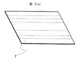
図3(a)は、他の実施形態に係る絶縁紙7の斜視図である。図3(b)は、絶縁紙7が折り曲げられた状態を示す斜視図である。図3(c)は、絶縁紙7を固定子コア1に挿入した状態を示す部分斜視図である。
FIG. 3A is a perspective view of insulating
絶縁紙7は、厚さが0.2mm以下と非常に薄く、アラミドなどの高強度かつ絶縁体により構成されたノーメックスなどが望ましい。また絶縁紙7は、固定子コア1の軸方向長よりも数mm長く形成される。
The insulating
図3(a)に示されるように、絶縁紙7は、間隔を空けて谷折りされる。そして図3(a)に示されるように、絶縁紙7は、断面がB字型の形状であるスロットライナーとなる。
As shown in FIG. 3(a), the insulating
このスロットライナーが複数設けられかつ固定子コア1の1つのスロットに複数個配置することで、絶縁構造が為される。図3(c)に示されるように、3個のB字型の絶縁紙7がスロットに径方向に3個配置される。
By providing a plurality of slot liners and arranging a plurality of slot liners in one slot of the
このスロットライナーは、スロットの軸方向から挿入することができるため、図示のように、アスロットの形状はセミクローズドスロット(スロット開口部が半分閉じているスロット形状)であってもよい。 Since this slot liner can be inserted from the axial direction of the slot, the shape of the slot may be a semi-closed slot (slot shape in which the slot opening is half closed) as shown.
図3(a)ないし(c)に示される実施形態では、固定子コア1を電磁鋼板の一体もので構成した場合の例を示したが、先に示した分割コア構造の場合においても採用可能である。絶縁紙スロットライナーを採用するメリットは、紙が厚さ0.2mm以下と薄いために、導体の占積率を高めることが可能である。樹脂ボビン成形体の厚さは、現在のところ、軸方向長などにもよるが0.3mm程度が限界である。
In the embodiment shown in FIGS. 3(a) to 3(c), an example in which the
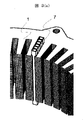
図4(a)は、本実施形態に係るセグメント導体3の固定子コア1への配置例を示す部分斜視図である。
FIG. 4(a) is a partial perspective view showing an arrangement example of the
本実施形態では、固定子コア1は48個のスロットを設ける。そして、固定子コア1の回転子磁極数が8極である場合、セグメント導体3により構成される分布巻コイルの跨りは45度の角度を有する。
In this embodiment, the
図4(a)に示されるように、それぞれのセグメント導体3は、6スロットを飛び越えて跨っている。ひとつのスロット角度が7.5度であるため、セグメント導体3の足同士の角度は45度の角度となっている。
As shown in FIG. 4(a), each
図4(b)は、図4(a)に示された固定子コア1の上面図である。
FIG. 4(b) is a top view of the
セグメント導体3の片方の足は、径方向の外周側1層目のスロット挿入穴に配置される。セグメント導体3のコイルエンド頂点部で折り曲げられる。そしてセグメント導体3のもう片方の足は、径方向の外周側2層目に入っている。ここで、一つのセグメント導体3を挿入した状態では、隣のスロットを塞いでしまうので、隣り合う次のコイルの挿入が困難であることがわかる。
One leg of the
図4(c)は、図4(a)で示されたセグメント導体3を周方向に48個並べた状態(コイルがすべて挿入された状態)のコイルエンド部を示す部分斜視図である。セグメント導体3が整列されて並んでいる状態では、干渉なく挿入ができる形状となっている。
FIG. 4(c) is a partial perspective view showing a coil end portion in a state in which 48
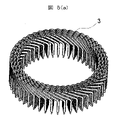
図5(a)は、図4(c)の固定子コア1を取り除いき複数のセグメント導体3だけを示す斜視図である。セグメント導体3が固定子コア1に挿入される状態で整列した状態では、セグメント導体3のコイルエンド部はきれいに整列され、スロットに挿入されるコイルも軸方向と径方向と周方向とも整列されていることがわかる。この状態を保持できれば、固定子コア1への挿入が容易となることがわかる。そこで、この状態を保ったまま、セグメント導体3のコイル群を固定することを考えた。
FIG. 5(a) is a perspective view showing only a plurality of
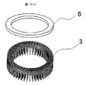
図5(b)は、図5(a)で示されたセグメント導体3のコイル群のコイルエンドの頂点部近くの一部を樹脂モールドリング部6によってコイル群を固めた状態を示す斜視図である。
FIG. 5(b) is a perspective view showing a state in which a part of the coil group of the
これによって、セグメント導体3のコイル群はその姿勢を保ち、コイル群を一体ものとして扱うことが出来るようになる。この一体化されたコイル群を図1(c)で示したように組立するのである。
As a result, the coil group of the
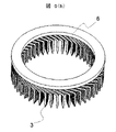
図6(a)は、図5(c)で示された別体に構成された樹脂モールドリング部6を示す下面図である。
FIG. 6(a) is a bottom view showing the separately configured resin
樹脂モールドリング部6は、あらかじめモールド成形される。樹脂モールドリング部6は、リング状部品の片面に、整列されたコイルエンド群のコイルエンド頂点部が精度よく保持されるような複数の凹み形状が形成される。
The resin
図6(b)は、別体に構成された樹脂モールドリング部6の全体斜視図である。
FIG. 6(b) is an overall perspective view of the resin
径方向に3層分設けられるセグメント導体3はそれぞれ、樹脂モールドリング部6の円環状の壁によって絶縁及び隔離される。
The
また樹脂モールドリング部6は、セグメント導体3のコイルエンドの頂点部分の形状をしっかり保持できる同一形状を有している。
Also, the resin molded
この樹脂モールドリング部6をセグメント導体3のコイル群に被せて接着固定することによって、図5(b)で示した構造と同様の効果を得ることができる。樹脂モールドに比べ、大規模な設備が不要であること、接着剤の選定によっては、早く硬化させられる可能性もある。また、部品として作り込みが可能なので、肉厚を薄くすることや、樹脂の材質を種々選ぶことができるなどの功かもある。さらに、セラミックなどの高熱伝導部材での構成も可能である。
By covering and fixing the coil group of the
図7(a)は、図5及び図6で示された樹脂モールドリング部6で一体化されたセグメント導体3及び4のコイル群を固定子コア1に組み付ける途中の状態を示す斜視図を示す。図7(b)は、樹脂モールドリング部6で一体化されたセグメント導体3及び4のコイル群を固定子コア1に組み付けた状態を示す斜視図を示す。
FIG. 7(a) is a perspective view showing a state in which the coil group of the
図7(a)に示されるように、軸方向上部から凸型の先端を持つセグメント導体3のコイル群が固定子コア1に挿入される。また軸方向下側から先端部に凹型の接続部を有するセグメント導体4のコイル群がボビン2を介してスロットに挿入される。
As shown in FIG. 7(a), a coil group of
固定子コア1の軸方向下側からセグメント導体4のコイル群が挿入後は、プレスによる軸方向加圧によって、セグメント導体3のコイル群、固定子コア1、セグメント導体4のコイル群が軸方向の寸法関係で所定の位置になるように加圧成形する。
After the coil group of the
セグメント導体3及び4のコイル群の先端形状は、前述したように、しまり嵌め以上に寸法関係となっているが、樹脂モールドリング部6に軸方向に平行な加圧をすることにより、均一に応力がかけられるので、しっかりと結合することができる。
As described above, the end shapes of the coil groups of the
図8(a)は、本実施形態に係る固定子と回転子の関係を説明する斜視図である。 FIG. 8(a) is a perspective view illustrating the relationship between the stator and the rotor according to this embodiment.
本実施形態に係るモータの回転子は、永久磁石12と、永久磁石12を収納しかつ回転するロータコア13と、ロータコア13を支持する軸11と、を備える。本実施例では永久磁石同期モータの場合の例を示しているが、回転子は、誘導モータの籠型導体回転子でも、リラクタンスモータの磁性体突極回転子でも良い。
The rotor of the motor according to this embodiment includes
永久磁石同期モータの場合は、ロータコア13の内部または表面に永久磁石12が配置されている。固定子の内側に回転子が配置され、ギャップを介して回転子表面と固定子内面が対向し、磁束のやり取りを行ってモータとして動作する。
In the case of a permanent magnet synchronous motor, the
図8(b)は、本実施形態に係るモータが組み立てられた形態を示す軸方向の断面図である。 FIG. 8(b) is an axial cross-sectional view showing an assembled form of the motor according to the present embodiment.
軸11には、軸11の出力側にボールベアリング14、反出力側にボールベアリング15が接触される。ボールベアリング14及び15の外周が固定された状態でベアリングの内周面が軸と一体となって回転可能に保持される。
A
ボールベアリング14の外周は、出力側軸受保持部16により保持される。ボールベアリング15の外周は、反出力側軸受保持部17で保持される。
The outer circumference of the
出力側軸受保持部16及び反出力側軸受保持部17はハウジング20により、同軸度を保った状態で構成される。
The output-side
ハウジング20には、軸方向にボルト18及び19で締め付けて軸方向に応力を加えて保持される構成となっている。固定子は、ハウジング20の軸方向の所定の場所に保持され固定されている。この状態で、コイル群を一体化している樹脂モールドリング部6は、出力側及び反出力側とも、軸受保持部の軸方向面と接触し、軸方向に応力をかけた状態で保持される。
The
これによって、モータとして回転子がトルク脈動や、負荷変動により振動して、固定子に振動や応力が加わった場合においても、ハウジング20が固定子コイル群が抜け出てきたりすることを防ぐ。
As a result, even when the rotor vibrates as a motor due to torque pulsation or load fluctuation and vibration or stress is applied to the stator, the
また、この構造により、コイルエンド部分から、軸受保持部にコイルで発生したジュール損失による発熱を熱伝導によって冷却できる効果も有する。さらに、樹脂モールドしていないコイルエンド部分には、通常、冷却油(潤滑油)をかける冷却法が採用されることが多く、樹脂で囲われていないセグメント導体3及び4のコイルエンドに直接塗布することができるため、油冷効果を減少させることが無い。 This structure also has the effect of cooling heat generated by Joule loss generated in the coil from the coil end portion to the bearing holding portion by heat conduction. Furthermore, a cooling method in which cooling oil (lubricating oil) is usually applied to the coil end portions that are not resin-molded is often adopted. Therefore, the oil cooling effect is not reduced.
また、セグメント導体3及び4をしっかりと軸方向に保持し続けることで、セグメント導体3及び4の完全な固定が出来るので、これまでセグメント導体3及び4の固定に必要であったワニス処理(樹脂によるコイルの固定)工程が不要となり、モータの製造工程を短縮することができる。ワニス処理は、ワニスを乾燥させる乾燥炉(通常は連続炉)が必要となるため、その乾燥炉の投資費用、製造時の熱量(電気代)などの費用の低減にもつながる。
In addition, by continuing to hold the
図9(a)は、セグメント導体3とセグメント導体4の接続形態を示す斜視図である。図9(b)は、セグメント導体3とセグメント導体4の接続形態を示す正面図である。
FIG. 9(a) is a perspective view showing the form of connection between the
セグメント導体3の凸部とセグメント導体4の凹部の接続は、ボビン2内で区切られた部屋の中で行われるため、ボビン2のスロットの幅方向の寸法をしっかり設計することが重要である。
Since the projections of the
凹凸形状の場合、凸と凹の寸法をしまり嵌め以上の寸法で作成しても、ボビンスロットの寸法が緩いと凹の溝が外側に開いてしまって、きちんと接続できない状態となる。従って、ボビン2の幅方向の寸法は、セグメント導体3とセグメント導体4の平角の外形寸法とほぼ同等であることが望ましい。
In the case of uneven shapes, even if the dimensions of the protrusions and recesses are greater than the tight fit, if the dimensions of the bobbin slots are loose, the grooves of the recesses open outward, resulting in a state in which proper connection cannot be made. Therefore, it is desirable that the dimension of the
組立のための隙間公差は、少なくとも本実施例の2mmから3mm程度の外径寸法の場合で20ミクロン程度とし、嵌合時に外に開かないような寸法関係としたい。 The clearance tolerance for assembly should be at least about 20 microns in the case of the outer diameter dimension of about 2 mm to 3 mm in this embodiment, and it is desirable to have a dimensional relationship that does not open outward when fitted.
また、図9(b)に示されるように、セグメント導体3とセグメント導体4のヘアピンコイルの足がそれぞれ異なる長さとなっている状態を示している。これにより、接続される箇所が軸方向で異なるので、径方向の溝一つ置きに異なる軸方向位置で接続される。
Also, as shown in FIG. 9B, the legs of the hairpin coils of the
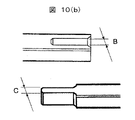
図10(a)は、セグメント導体3とセグメント導体4の嵌合部の比較例としての製作方法を示す部分斜視図である。
FIG. 10(a) is a partial perspective view showing a manufacturing method as a comparative example of the fitting portion of the
セグメント導体3とセグメント導体4は平角線の状態から、凸部と凹部を同時にプレス打ち抜きすることで、材料の歩留りを上げ、プレス回数を最小とすることができる。このときには、凹部と凸部の寸法関係はAで示すように同一の寸法となってしまう。スプリングバックにより、多少の寸法差はできるが、積極的に溝と突起の寸法を設定することは困難である。
The
図10(b)は、本実施形態に係るセグメント導体3とセグメント導体4の嵌合部の製作方法を示す部分斜視図である。
FIG. 10(b) is a partial perspective view showing a method of manufacturing the fitting portion of the
セグメント導体3とセグメント導体4の先端を互いに違う箇所で寸法を規定してプレス加工し、溝の寸法をB、突起の寸法をCのように異なった寸法関係にする。このとき、B=1.5(-0.02mm~0mm)、C=1.5(0mm~+0.02mm)などのように凸部の寸法を大きく設定ししまり嵌めとすることが望ましい。
The ends of the
図10(c)は、セグメント導体3とセグメント導体4の先端部周辺の部分斜視図である。
FIG. 10(c) is a partial perspective view of the periphery of the
セグメント導体3とセグメント導体4の加工は微小な寸法の管理が困難であるため、余裕のある寸法関係に打ち抜きしておき、スズ、金、銀などの導電性メッキ21及び22によってその寸法を作り込む方法を示している。導電性メッキ21及び22は、銅の腐食対策にも有効であり、切断した後に、平角導体のエナメル被膜がついている部分以外の打ち抜き切断部にメッキを施す方法も有益である。
Since it is difficult to manage minute dimensions in the processing of the
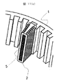
図11(a)は、他の実施形態に係るボビン2の斜視図である。図11(b)は、固定子コア1のティース部5がボビン2に挿入される前の全体斜視図である。図11(c)は、ティース部5が固定子コア1に固定された部分斜視図である。
FIG. 11(a) is a perspective view of a
固定子コア1がティース部5とコアバック部分に分かれた構造の分割コアにおいて、ティース部5の材料の保持をボビン2で行う。ティース部5は、磁束が集中するため、カシメなどの残留応力で鉄損が増加するので、切断しただけの状態で保持を行いたい。
In a split core structure in which a
その場合に図11(a)に示すような樹脂製のボビン2で保持を行うことが有効である。ティース部5を構成する材料は、鉄基アモルファス箔帯や、高磁束密度が実現可能なナノ結晶合金、またはファインメットや、6.5%Si含有の薄電磁鋼板などが挙げられる。これらの鉄心を切断したものを図11(b)に示すようにボビン2に挿入することで保持を行う。この時のボビン2は、セグメント導体3とセグメント導体4が挿入される部屋を区切るための壁を有している。ティース部5をコアバックコアに組み立てた状態を図11(c)に示す。
In that case, it is effective to hold the
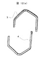
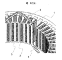
図12(a)は、他の実施形態に係るセグメント導体3とセグメント導体4の斜視図である。図12(b)は、他の実施形態に係るセグメント導体3とセグメント導体4のボビン2への接続状態を示す斜視図である。
FIG. 12(a) is a perspective view of a
図1及び図9で示した向きと90度回転した方向に溝(凹部)、突起(凸部)が向いている形状となっている。これは、図12(b)に示すように、図11で示したボビン2が、隣り合わせで重なるとき、接続箇所の横断面の凹面がボビンの壁同士の合わさり面に来ることを避けるためである。
The grooves (concave portions) and projections (convex portions) are oriented in a direction rotated 90 degrees from the directions shown in FIGS. 1 and 9 . This is because, as shown in FIG. 12(b), when the
同一のスロットには、同相のコイルが配置されるため、電位差は少なく、荷電部が露出していても問題無いのであるが、その面が大きいと、不純物の含有などによって接触し、並列コイルとなってしまうことを少しでも避けるためである。 Since the coils of the same phase are arranged in the same slot, the potential difference is small and there is no problem even if the charged part is exposed. This is to avoid, even if only a little, what will happen.
このような場合には、スロット内のワニス含浸処理や、スロット内部に潤滑油(ATF)の侵入を防止するためのシール処理を行うことも必要である。ティース部(一体型コアでもティース部が高級グレード鋼板であるばあいも含んで)に磁気特性の優れた材料を用いる場合に、セグメント導体3とセグメント導体4を曲げる工程を経ることによってセグメント導体3とセグメント導体4から固定子ティース部分に応力を付与することになる。
In such a case, it is necessary to impregnate the inside of the slot with varnish, or to perform a sealing treatment to prevent lubricating oil (ATF) from entering the inside of the slot. When using a material with excellent magnetic properties for the teeth (including the case where the teeth are made of high-grade steel plate even in the integrated core), the
この場合、高級鉄板は、応力をかけると磁気特性が劣化して磁化特性が悪くなったり、鉄損が大幅に増加したりする。本実施形態の組み合て方法ではセグメント導体3とセグメント導体4には、軸方向に平行な応力しかかからないため、ティースコアにはまったく応力をかけることなく製造することが可能である。また、余計な応力がかからないので、絶縁性能にも負担をかけないことも大きな効果である。
In this case, when stress is applied to the high-grade iron plate, the magnetic properties deteriorate, and the magnetization properties deteriorate, or the iron loss increases significantly. In the combination method of this embodiment, only stress parallel to the axial direction is applied to the
1…固定子コア、2…ボビン、3…セグメント導体、4…セグメント導体、5…ティース部、6…樹脂モールドリング部、7…絶縁紙、8…樹脂モールドリング部、11…軸、12…永久磁石、13…ロータコア、14…ボールベアリング、15…ボールベアリング、16…出力軸側軸受保持部、17…反出力軸側軸受保持部、18…ボルト、19…ボルト、20…ハウジング、21…導電性メッキ、22…導電性メッキ
DESCRIPTION OF
Claims (8)
前記複数のセグメント導体が分布巻の状態で挿入される固定子コアと、を備え、
前記複数のセグメント導体は、互いに接続される先端部に凸形状と凹形状がそれぞれ形成され、
前記凸形状と前記凹形状は、軸方向垂直方向が接触面となる組み合わせ面を有し、
前記凸形状の凸側寸法は、前記凹形状の凹側寸法よりも大きく形成され、
前記複数のセグメント導体により構成されるコイルエンドの頂点部には、予めモールド成形された樹脂モールドリング部を備え、
前記樹脂モールドリング部には、前記コイルエンドの頂点部が保持される複数の凹みと、径方向に設けられる前記セグメント導体を絶縁及び隔離する円環状の壁とが形成され、
前記樹脂モールドリング部に前記コイルエンドの頂点部を被せて接着剤で接着固定することで一体化されるコイル群を構成する分布巻ラジアルギャップ型回転電機の固定子。 a plurality of U-shaped segment conductors;
a stator core into which the plurality of segment conductors are inserted in a distributed winding state;
each of the plurality of segment conductors has a convex shape and a concave shape at the ends connected to each other,
The convex shape and the concave shape have a combination surface that is a contact surface in the direction perpendicular to the axial direction,
The convex side dimension of the convex shape is formed larger than the concave side dimension of the concave shape,
A pre-molded resin-molded ring portion is provided at the apex portion of the coil end configured by the plurality of segment conductors,
The resin mold ring portion is formed with a plurality of recesses for holding the vertexes of the coil ends, and an annular wall for insulating and isolating the segment conductors provided in the radial direction ,
A stator for a distributed winding radial gap type electric rotating machine, which constitutes a coil group integrated by covering the resin mold ring portion with the apex portion of the coil end and bonding and fixing the same with an adhesive .
前記コイル群は、前記固定子コアを境に軸方向のどちらか一方だけに形成される分布巻ラジアルギャップ型回転電機の固定子。 A stator for a distributed winding radial gap type electric rotating machine according to claim 1,
A stator of a distributed winding radial gap type rotating electric machine in which the coil group is formed only in one of axial directions with respect to the stator core.
前記コイル群は、前記固定子コアを境に軸方向の双方に形成される分布巻ラジアルギャップ型回転電機の固定子。 A stator for a distributed winding radial gap type electric rotating machine according to claim 1,
The coil group is a stator of a distributed winding radial gap type rotary electric machine in which the coil groups are formed in both axial directions with respect to the stator core.
前記セグメント導体同士の接続部は、前記固定子コアに設けられたボビンにより構成されたスロット溝に配置される挿入される分布巻ラジアルギャップ型回転電機の固定子。 A stator for a distributed winding radial gap type rotating electric machine according to any one of claims 1 to 3 ,
A stator for a distributed winding radial gap type rotary electric machine in which connecting portions between the segment conductors are inserted into slot grooves formed by bobbins provided in the stator core.
前記セグメント導体同士の接続部は、前記固定子コアに設けられた絶縁紙で覆われた状態でスロット溝に挿入される分布巻ラジアルギャップ型回転電機の固定子。 A stator for a distributed winding radial gap type rotating electric machine according to any one of claims 1 to 3 ,
A stator for a distributed winding radial gap type rotary electric machine in which connecting portions between the segment conductors are inserted into slot grooves while being covered with insulating paper provided on the stator core.
前記セグメント導体同士の接続部である前記凸形状と前記凹形状は、スズ、金、銀を含有するメッキ処理が施される分布巻ラジアルギャップ型回転電機の固定子。 A stator for a distributed winding radial gap type rotating electrical machine according to any one of claims 1 to 5 ,
A stator for a distributed winding radial gap type rotating electric machine, wherein the convex shape and the concave shape, which are the connecting portions between the segment conductors, are plated with tin, gold, and silver.
前記固定子コアは、アモルファスやナノ結晶合金を含む材料でありかつコアバック部分よりも磁気特性に優れる材料により構成されるティース部を有する分布巻ラジアルギャップ型回転電機の固定子。 A stator for a distributed winding radial gap type rotating electric machine according to any one of claims 1 to 6 ,
The stator core is a stator for a distributed winding radial gap type electric rotating machine, and has teeth portions made of a material containing an amorphous or nanocrystalline alloy and having magnetic properties superior to those of a core back portion.
前記固定子のコイルエンド頂点部に配置される樹脂モールド部分をモータ筺体部分と接触させて保持させる分布巻ラジアルギャップ型回転電機。 A distributed winding radial gap type rotating electric machine comprising the stator according to any one of claims 1 to 7 ,
A distributed winding radial gap rotating electrical machine in which a resin mold portion arranged at the coil end apex portion of the stator is held in contact with a motor housing portion.
Applications Claiming Priority (3)
| Application Number | Priority Date | Filing Date | Title |
|---|---|---|---|
| JP2018134662 | 2018-07-18 | ||
| JP2018134662 | 2018-07-18 | ||
| PCT/JP2019/019024 WO2020017133A1 (en) | 2018-07-18 | 2019-05-14 | Distributed-winding, radial-gap-type rotary electric machine and stator thereof |
Publications (2)
| Publication Number | Publication Date |
|---|---|
| JPWO2020017133A1 JPWO2020017133A1 (en) | 2021-03-11 |
| JP7142700B2 true JP7142700B2 (en) | 2022-09-27 |
Family
ID=69164674
Family Applications (1)
| Application Number | Title | Priority Date | Filing Date |
|---|---|---|---|
| JP2020530906A Active JP7142700B2 (en) | 2018-07-18 | 2019-05-14 | Distributed winding radial gap type rotary electric machine and its stator |
Country Status (3)
| Country | Link |
|---|---|
| JP (1) | JP7142700B2 (en) |
| CN (1) | CN112368912B (en) |
| WO (1) | WO2020017133A1 (en) |
Cited By (1)
| Publication number | Priority date | Publication date | Assignee | Title |
|---|---|---|---|---|
| WO2024080404A1 (en) * | 2022-10-13 | 2024-04-18 | 엘지마그나 이파워트레인 주식회사 | Stator of rotating electric machine and method for manufacturing same |
Families Citing this family (8)
| Publication number | Priority date | Publication date | Assignee | Title |
|---|---|---|---|---|
| JP7344807B2 (en) * | 2020-02-10 | 2023-09-14 | 株式会社日立ハイテク | Coil bobbin, stator core of distributed winding radial gap type rotating electrical machine, and distributed winding radial gap type rotating electrical machine |
| DE102020104508A1 (en) * | 2020-02-20 | 2021-08-26 | Elringklinger Ag | Winding and manufacturing process |
| JP7124017B2 (en) | 2020-07-31 | 2022-08-23 | 本田技研工業株式会社 | Magnetizing yoke and manufacturing method thereof |
| DE102020210519A1 (en) * | 2020-08-19 | 2022-02-24 | Robert Bosch Gesellschaft mit beschränkter Haftung | electrical machine |
| US11658530B2 (en) | 2021-07-15 | 2023-05-23 | Stoneridge, Inc. | Modular brushless DC (BLDC) motor construction |
| JP2023057947A (en) | 2021-10-12 | 2023-04-24 | 株式会社日立産機システム | Rotary electric machine and industrial machine |
| JP2023105875A (en) * | 2022-01-20 | 2023-08-01 | 株式会社日立産機システム | Rotary electric machine and industrial machine |
| CN115967211A (en) * | 2023-02-14 | 2023-04-14 | 蔚来动力科技(合肥)有限公司 | Motor stator and motor |
Citations (4)
| Publication number | Priority date | Publication date | Assignee | Title |
|---|---|---|---|---|
| JP2005269782A (en) | 2004-03-18 | 2005-09-29 | Nissan Motor Co Ltd | Stator structure of motor and manufacturing method of motor stator |
| JP2009194999A (en) | 2008-02-13 | 2009-08-27 | Denso Corp | Manufacturing method of stator coil |
| JP2016086598A (en) | 2014-10-28 | 2016-05-19 | トヨタ自動車株式会社 | Connection end insulation method for stator coil |
| JP2016187245A (en) | 2015-03-27 | 2016-10-27 | 本田技研工業株式会社 | Manufacturing method of stator and stator |
Family Cites Families (5)
| Publication number | Priority date | Publication date | Assignee | Title |
|---|---|---|---|---|
| JPS62189948A (en) * | 1986-02-13 | 1987-08-19 | Toshiba Corp | Insulation treating method for coil end connecting section for rotary electric machine |
| US8841811B2 (en) * | 2010-08-18 | 2014-09-23 | Remy Technologies Llc | Conductor insulation arrangement for an electric machine |
| JP5839851B2 (en) * | 2011-06-23 | 2016-01-06 | 日立オートモティブシステムズ株式会社 | Rotating electric machine |
| EP2933901B1 (en) * | 2014-04-15 | 2016-10-26 | Siemens Aktiengesellschaft | Stator of an electric machine and production thereof |
| CN108028556B (en) * | 2015-09-17 | 2020-02-14 | 日立汽车系统株式会社 | Rotating electrical machine |
-
2019
- 2019-05-14 WO PCT/JP2019/019024 patent/WO2020017133A1/en active Application Filing
- 2019-05-14 JP JP2020530906A patent/JP7142700B2/en active Active
- 2019-05-14 CN CN201980019879.5A patent/CN112368912B/en active Active
Patent Citations (4)
| Publication number | Priority date | Publication date | Assignee | Title |
|---|---|---|---|---|
| JP2005269782A (en) | 2004-03-18 | 2005-09-29 | Nissan Motor Co Ltd | Stator structure of motor and manufacturing method of motor stator |
| JP2009194999A (en) | 2008-02-13 | 2009-08-27 | Denso Corp | Manufacturing method of stator coil |
| JP2016086598A (en) | 2014-10-28 | 2016-05-19 | トヨタ自動車株式会社 | Connection end insulation method for stator coil |
| JP2016187245A (en) | 2015-03-27 | 2016-10-27 | 本田技研工業株式会社 | Manufacturing method of stator and stator |
Cited By (1)
| Publication number | Priority date | Publication date | Assignee | Title |
|---|---|---|---|---|
| WO2024080404A1 (en) * | 2022-10-13 | 2024-04-18 | 엘지마그나 이파워트레인 주식회사 | Stator of rotating electric machine and method for manufacturing same |
Also Published As
| Publication number | Publication date |
|---|---|
| JPWO2020017133A1 (en) | 2021-03-11 |
| CN112368912B (en) | 2023-09-08 |
| CN112368912A (en) | 2021-02-12 |
| WO2020017133A1 (en) | 2020-01-23 |
Similar Documents
| Publication | Publication Date | Title |
|---|---|---|
| JP7142700B2 (en) | Distributed winding radial gap type rotary electric machine and its stator | |
| JP7344807B2 (en) | Coil bobbin, stator core of distributed winding radial gap type rotating electrical machine, and distributed winding radial gap type rotating electrical machine | |
| JP5879121B2 (en) | Axial gap rotating electric machine | |
| JP5519808B2 (en) | Stator and rotating electric machine including the stator | |
| JP5734794B2 (en) | Stator and rotating electric machine including the stator | |
| JP2001238377A (en) | Rotating electric machine | |
| CN110741533B (en) | Rotating electrical machine | |
| JP2010239691A (en) | Stator of rotary electric machine, and rotary electric machine | |
| CN114128091A (en) | Coil, stator, and motor | |
| WO2020174817A1 (en) | Dynamo-electric machine stator, dynamo-electric machine, method for manufacturing dynamo-electric machine stator, and method for manufacturing dynamo-electric machine | |
| US20180145549A1 (en) | Rotary electric machine and manufacturing method for rotary electric machine | |
| JP7254140B1 (en) | Rotating electric machine | |
| JP4386909B2 (en) | motor | |
| JP5609937B2 (en) | Rotating electric machine stator | |
| JP2018133850A (en) | Rotary electric machine | |
| JP6843272B2 (en) | Manufacturing method of stator of rotary electric machine and stator of rotary electric machine | |
| JP7195180B2 (en) | Stator and rotating electric machine | |
| JP4372130B2 (en) | motor | |
| JP7166207B2 (en) | Rotating electric machine and its manufacturing method | |
| JP2018074877A (en) | Stator for rotary electric machine, and rotary electric machine | |
| JP7216254B2 (en) | stator | |
| JP7123716B2 (en) | How to install the stator, motor and bus ring | |
| JP2023000668A (en) | motor | |
| JP5233385B2 (en) | Rotating electric machine stator and rotating electric machine | |
| JP2015029370A (en) | Stator core for rotary electric machine, and brushless motor |
Legal Events
| Date | Code | Title | Description |
|---|---|---|---|
| A621 | Written request for application examination |
Free format text: JAPANESE INTERMEDIATE CODE: A621 Effective date: 20200915 |
|
| A131 | Notification of reasons for refusal |
Free format text: JAPANESE INTERMEDIATE CODE: A131 Effective date: 20210720 |
|
| A521 | Request for written amendment filed |
Free format text: JAPANESE INTERMEDIATE CODE: A523 Effective date: 20210902 |
|
| A131 | Notification of reasons for refusal |
Free format text: JAPANESE INTERMEDIATE CODE: A131 Effective date: 20220222 |
|
| A521 | Request for written amendment filed |
Free format text: JAPANESE INTERMEDIATE CODE: A523 Effective date: 20220329 |
|
| TRDD | Decision of grant or rejection written | ||
| A01 | Written decision to grant a patent or to grant a registration (utility model) |
Free format text: JAPANESE INTERMEDIATE CODE: A01 Effective date: 20220823 |
|
| A61 | First payment of annual fees (during grant procedure) |
Free format text: JAPANESE INTERMEDIATE CODE: A61 Effective date: 20220913 |
|
| R150 | Certificate of patent or registration of utility model |
Ref document number: 7142700 Country of ref document: JP Free format text: JAPANESE INTERMEDIATE CODE: R150 |