以下、液体収容容器及びこれを備える記録装置の一実施形態について図を参照しながら説明する。記録装置は、例えば、用紙等の媒体に液体の一例であるインクを噴射することによって、文字、写真等の画像を記録するインクジェット式のプリンターである。液体収容容器は、例えば、インクを収容可能なタンクである。
An embodiment of a liquid storage container and a recording apparatus including the same will be described below with reference to the drawings. A recording apparatus is, for example, an inkjet printer that records images such as characters and photographs by ejecting ink, which is an example of liquid, onto a medium such as paper. The liquid storage container is, for example, a tank that can store ink.
(第1実施形態)
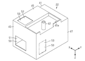
図1に示すように、記録装置11は、筐体12を備える。筐体12は、直方体状に形成される。そのため、筐体12は、前面13、後面、上面15、下面、右側面17及び左側面の6つの面を有する。
(First embodiment)
As shown in FIG. 1, the recording device 11 has a housing 12 . The housing 12 is formed in a rectangular parallelepiped shape. Therefore, the housing 12 has six surfaces: a front surface 13, a rear surface, a top surface 15, a bottom surface, a right side 17 and a left side.
記録装置11は、媒体99に液体を吐出して画像を記録する記録ヘッド21と、記録ヘッド21に供給する液体を収容可能な液体収容容器22と、記録ヘッド21及び液体収容容器22を搭載するキャリッジ23とを備える。キャリッジ23は筐体12に収容される。そのため、記録ヘッド21及び液体収容容器22は筐体12に収容される。
The recording apparatus 11 includes a recording head 21 that ejects liquid onto a medium 99 to record an image, a liquid container 22 that can contain the liquid that is supplied to the recording head 21, the recording head 21, and the liquid container 22. and a carriage 23 . A carriage 23 is housed in the housing 12 . Therefore, the recording head 21 and the liquid container 22 are housed in the housing 12 .
筐体12は、記録ヘッド21によって液体を吐出された媒体99が排出されるための排出口24を有する。筐体12において、排出口24が設けられる面が前面13である。画像を記録された媒体99は、排出口24を介して筐体12内から筐体12外に排出される。媒体99は、例えば筐体12の後面に開口する供給口を通じて筐体12内に供給される。すなわち、第1実施形態の記録装置11は、筐体12内において、筐体12の後面から前面13に向けて媒体99を搬送する。そのため、第1実施形態において、筐体12の後面から前面13に向かう方向が媒体99の搬送方向である。
The housing 12 has a discharge port 24 through which the medium 99 ejected with liquid by the recording head 21 is discharged. The front surface 13 of the housing 12 is the surface on which the outlet 24 is provided. The medium 99 on which the image is recorded is ejected from the inside of the housing 12 to the outside of the housing 12 through the ejection port 24 . The medium 99 is supplied into the housing 12 through, for example, a supply port opening on the rear surface of the housing 12 . That is, the recording apparatus 11 of the first embodiment conveys the medium 99 from the rear surface of the housing 12 toward the front surface 13 within the housing 12 . Therefore, in the first embodiment, the direction from the rear surface of the housing 12 to the front surface 13 is the transport direction of the medium 99 .
筐体12は、その前面13に、開閉可能な前面カバー25を有する。前面カバー25は、筐体12の下面寄りとなる端部を軸に開閉可能である。図1における記録装置11においては、前面カバー25は閉じている。このときの前面カバー25は、排出口24を覆うとともに筐体12の前面13の少なくとも一部を構成する。前面カバー25を開くと、筐体12内が露出される。前面カバー25を開くことにより、排出口24から媒体99が排出可能となる。
The housing 12 has an openable and closable front cover 25 on its front surface 13 . The front cover 25 can be opened and closed around the end near the bottom surface of the housing 12 . In the recording apparatus 11 shown in FIG. 1, the front cover 25 is closed. The front cover 25 at this time covers the discharge port 24 and constitutes at least part of the front surface 13 of the housing 12 . When the front cover 25 is opened, the inside of the housing 12 is exposed. The medium 99 can be discharged from the discharge port 24 by opening the front cover 25 .
筐体12は、その上面15に、開閉可能な上面カバー26を有する。上面カバー26は、筐体12の後面寄りとなる端部を軸に開閉可能である。図1における記録装置11においては、上面カバー26は閉じている。このときの上面カバー26は、筐体12の上面15の少なくとも一部を構成する。上面カバー26を開くと、筐体12内が露出される。記録装置11は、上面カバー26を開くことにより露出する開口を通じて媒体99を供給されてもよい。記録装置11は、筐体12に装着可能な媒体カセットから媒体99を供給されてもよい。
The housing 12 has an openable and closable top cover 26 on its top surface 15 . The upper surface cover 26 can be opened and closed around the end near the rear surface of the housing 12 . In the recording apparatus 11 in FIG. 1, the top cover 26 is closed. The top cover 26 at this time constitutes at least part of the top surface 15 of the housing 12 . When the top cover 26 is opened, the inside of the housing 12 is exposed. Recording device 11 may be fed media 99 through an opening exposed by opening top cover 26 . The recording device 11 may be supplied with the medium 99 from a medium cassette mountable in the housing 12 .
第1実施形態において、筐体12の前面13から後面に向かう方向が筐体12の奥行方向Yである。筐体12の奥行方向Yは、媒体99の搬送方向と反対方向となる。筐体12の前面13を正面に見たときに、右側に位置する側面が筐体12の右側面17であり、左側に位置する側面が筐体12の左側面である。筐体12の右側面17から筐体12の左側面に向かう方向が筐体12の幅方向Xである。筐体12の幅方向Xは、媒体99の幅方向と一致する。記録装置11は、通常、水平面上に配置された状態で使用される。このとき、筐体12の上面15から下面に向かう方向が鉛直方向Zとなる。
In the first embodiment, the depth direction Y of the housing 12 is the direction from the front surface 13 to the rear surface of the housing 12 . The depth direction Y of the housing 12 is opposite to the medium 99 transport direction. When the front surface 13 of the housing 12 is viewed from the front, the side surface located on the right side is the right side surface 17 of the housing 12 and the side surface located on the left side is the left side surface of the housing 12 . The width direction X of the housing 12 is the direction from the right side 17 of the housing 12 toward the left side of the housing 12 . The width direction X of the housing 12 matches the width direction of the medium 99 . The recording device 11 is normally used while being placed on a horizontal plane. At this time, the vertical direction Z is the direction from the upper surface 15 of the housing 12 toward the lower surface.
キャリッジ23は、筐体12内において幅方向Xに往復移動可能に設けられる。記録ヘッド21は、キャリッジ23とともに移動しながら液体を媒体99に吐出することによって、媒体99に画像を記録する。キャリッジ23は、例えば記録ヘッド21が記録を実行しない場合に、ホームポジションにおいて待機する。第1実施形態において、キャリッジ23のホームポジションは、幅方向Xにおいて筐体12の右側面17寄りとなる位置である。図1におけるキャリッジ23はホームポジションに位置する。キャリッジ23は、記録ヘッド21が媒体99に液体を吐出しない場合、すなわち記録装置11が待機状態である場合に、ホームポジションにおいて静止する。キャリッジ23のホームポジションは、幅方向Xにおいて筐体12の左側面寄りとなる位置とされてもよい。
The carriage 23 is provided so as to be able to reciprocate in the width direction X within the housing 12 . The recording head 21 records an image on the medium 99 by ejecting liquid onto the medium 99 while moving together with the carriage 23 . The carriage 23 waits at the home position, for example, when the printhead 21 does not print. In the first embodiment, the home position of the carriage 23 is a position closer to the right side surface 17 of the housing 12 in the width direction X. As shown in FIG. The carriage 23 in FIG. 1 is located at the home position. The carriage 23 rests at the home position when the recording head 21 does not eject liquid onto the medium 99, that is, when the recording device 11 is in a standby state. The home position of the carriage 23 may be a position closer to the left side of the housing 12 in the width direction X.
筐体12は、筐体12内に位置する液体収容容器22を視認可能な開口30を有する。記録装置11は、開口30を介して、筐体12外から筐体12内を視認可能とされる。開口30は、筐体12を構成する複数の面のうち少なくとも1つの面に形成される。開口30は、筐体12の前面13、上面15、右側面17及び左側面のうち少なくとも1つの面に形成されることが好ましい。第1実施形態において、開口30は、筐体12の前面13及び上面15の2つの面にそれぞれ形成される。そのため、第1実施形態においては、筐体12の前面13に設けられる開口30を第1開口31、筐体12の上面15に設けられる開口30を第2開口32と称する。第2開口32は上面カバー26に形成される。
The housing 12 has an opening 30 through which the liquid container 22 positioned within the housing 12 can be viewed. The recording device 11 allows the inside of the housing 12 to be visually recognized from the outside of the housing 12 through the opening 30 . The opening 30 is formed in at least one of the multiple surfaces forming the housing 12 . The opening 30 is preferably formed in at least one of the front surface 13 , top surface 15 , right side 17 and left side of the housing 12 . In the first embodiment, the openings 30 are formed in two surfaces, the front surface 13 and the top surface 15 of the housing 12 respectively. Therefore, in the first embodiment, the opening 30 provided in the front surface 13 of the housing 12 is referred to as the first opening 31 and the opening 30 provided in the upper surface 15 of the housing 12 is referred to as the second opening 32 . A second opening 32 is formed in the top cover 26 .
開口30は、筐体12において、記録ヘッド21が記録を実行しない場合にキャリッジ23が待機する位置であるホームポジションと対応する位置に形成される。すなわち、開口30は、幅方向Xにおいて筐体12の右側面17寄りとなる位置に形成される。これにより、記録装置11が待機状態である場合に、開口30を介して液体収容容器22を視認し易い。
The opening 30 is formed in the housing 12 at a position corresponding to the home position where the carriage 23 waits when the recording head 21 does not perform recording. That is, the opening 30 is formed at a position closer to the right side 17 of the housing 12 in the width direction X. As shown in FIG. Thereby, when the recording apparatus 11 is in the standby state, it is easy to visually recognize the liquid container 22 through the opening 30 .
第1開口31は、筐体12の前面13において、上面15寄り且つ右側面17寄りとなる位置に形成される。第1開口31は、前面13を正面に見た場合に、前面13において右上に位置する隅部分に形成される。第2開口32は、筐体12の上面15において、前面13寄り且つ右側面17寄りとなる位置に形成される。第2開口32は、上面15を正面に見た場合に、上面15において右下に位置する隅部分に形成される。
The first opening 31 is formed on the front surface 13 of the housing 12 at a position closer to the upper surface 15 and closer to the right side surface 17 . The first opening 31 is formed in the upper right corner portion of the front surface 13 when the front surface 13 is viewed from the front. The second opening 32 is formed on the upper surface 15 of the housing 12 at a position closer to the front surface 13 and closer to the right side surface 17 . The second opening 32 is formed at a lower right corner portion of the upper surface 15 when the upper surface 15 is viewed from the front.
開口30は、筐体12の前面13、上面15に限らず、筐体12の後面、側面などに形成されてもよい。筐体12の側面に開口30が設けられる場合、その開口30を第3開口33と称する。ホームポジションが右側面17寄りに位置する場合、第3開口33は、右側面17及び左側面の2つの側面のうち、右側面17に設けられることが好ましい。ホームポジションが左側面寄りに位置する場合、第3開口33は、左側面に設けられることが好ましい。
The openings 30 are not limited to the front surface 13 and upper surface 15 of the housing 12 and may be formed in the rear surface, side surfaces, and the like of the housing 12 . When the opening 30 is provided in the side surface of the housing 12 , the opening 30 is called a third opening 33 . When the home position is located near the right side 17 , the third opening 33 is preferably provided on the right side 17 of the two sides, ie, the right side 17 and the left side. When the home position is positioned closer to the left side, the third opening 33 is preferably provided on the left side.
第3開口33は、筐体12の右側面17において、例えば図1において2点鎖線で示す位置に形成される。第3開口33は、右側面17において、前面13寄り且つ上面15寄りとなる位置に形成される。第3開口33は、右側面17を正面に見た場合に、右側面17において左上に位置する隅部分に形成される。第3開口33が設けられる場合、第1開口31、第2開口32及び第3開口33は、前面13、上面15及び右側面17によって形成される筐体12の角部分の周辺に位置する。
The third opening 33 is formed on the right side surface 17 of the housing 12, for example, at a position indicated by a two-dot chain line in FIG. The third opening 33 is formed on the right side surface 17 at a position closer to the front surface 13 and closer to the upper surface 15 . The third opening 33 is formed at the upper left corner portion of the right side surface 17 when the right side surface 17 is viewed from the front. If the third opening 33 is provided, the first opening 31 , the second opening 32 and the third opening 33 are located around corners of the housing 12 formed by the front surface 13 , the top surface 15 and the right side surface 17 .
開口30には、透明部材35が取り付けられる。透明部材35は、筐体12外から筐体12内を視認可能な程度の透明度を有する透明材料で形成される。透明部材35は、例えばプラスチック、ガラス、セラミックなどで形成される板状の部材である。開口30及び透明部材35は、液体収容容器22が収容する液体の残量を視認するための窓として機能する。開口30に透明部材35を取り付けることにより、筐体12外の塵埃が開口30を介して筐体12内に進入する虞を低減できる。第1実施形態において、透明部材35は、第1開口31、第2開口32のそれぞれに取り付けられる。第3開口33が設けられる場合は、第3開口33にも透明部材35が取り付けられる。
A transparent member 35 is attached to the opening 30 . The transparent member 35 is formed of a transparent material having such a degree of transparency that the inside of the housing 12 can be visually recognized from the outside of the housing 12 . The transparent member 35 is a plate-shaped member made of plastic, glass, ceramic, or the like. The opening 30 and the transparent member 35 function as windows for viewing the remaining amount of liquid contained in the liquid container 22 . By attaching the transparent member 35 to the opening 30 , it is possible to reduce the risk of dust outside the housing 12 entering the housing 12 through the opening 30 . In the first embodiment, the transparent member 35 is attached to each of the first opening 31 and the second opening 32 . When the third opening 33 is provided, the transparent member 35 is also attached to the third opening 33 .
透明部材35は、開口30に対して着脱可能であることが好ましい。こうすると、例えば記録ヘッド21が吐出する液体の飛沫によって透明部材35が汚れた場合に、透明部材35を容易に清掃できる。
The transparent member 35 is preferably detachable with respect to the opening 30 . By doing so, for example, when the transparent member 35 is soiled by droplets of the liquid ejected by the recording head 21, the transparent member 35 can be easily cleaned.
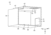
図2、図3、図4、図5、図6、図7、図8及び図9に示すように、液体収容容器22は、液体を収容可能な容器本体41と、容器本体41に液体を注入可能な注入部42とを備える。容器本体41は、キャリッジ23に装着可能に構成される。容器本体41をキャリッジ23に装着することによって、容器本体41が収容する液体を記録ヘッド21に供給可能となる。
As shown in FIGS. 2, 3, 4, 5, 6, 7, 8, and 9, the liquid storage container 22 includes a container body 41 capable of containing liquid, and a container body 41 containing liquid. and an injectable injection section 42 . The container body 41 is configured to be attachable to the carriage 23 . By mounting the container body 41 on the carriage 23 , the liquid contained in the container body 41 can be supplied to the recording head 21 .
容器本体41は複数の面で構成される。第1実施形態における容器本体41は、前面43、後面44、上面45、下面46、右側面47及び左側面48の6つの面を有する。容器本体41は、容器本体41内を露出可能な開口48aを有する。第1実施形態の容器本体41において、幅方向Xにおいて右側面47と反対側に位置する部分、すなわち左側面48側に開口48aが形成される。
The container body 41 is composed of a plurality of surfaces. The container body 41 in the first embodiment has six surfaces: a front surface 43 , a rear surface 44 , an upper surface 45 , a lower surface 46 , a right side 47 and a left side 48 . The container body 41 has an opening 48a through which the inside of the container body 41 can be exposed. In the container main body 41 of the first embodiment, an opening 48a is formed in a portion located on the opposite side of the right side 47 in the width direction X, that is, on the left side 48 side.
開口48aには、図3及び図9において2点鎖線で示すように、容器本体41内を封止する封止部材49が取り付けられる。そのため、容器本体41が開口48aを有する場合は、封止部材49が容器本体41の一面を構成する。第1実施形態において、封止部材49は、容器本体41の左側面48を構成する。
A sealing member 49 for sealing the interior of the container body 41 is attached to the opening 48a, as indicated by the two-dot chain lines in FIGS. Therefore, when the container body 41 has the opening 48a, the sealing member 49 constitutes one surface of the container body 41 . In the first embodiment, the sealing member 49 constitutes the left side surface 48 of the container body 41 .
封止部材49は、例えばフィルム、シート、プレートなどで構成され、開口48aに溶着される。封止部材49は、開口48aに対して例えば熱溶着される。容器本体41は、開口48aに封止部材49が取り付けられることにより、液体を収容可能となる。開口48aは、容器本体41においてその上面45側、右側面47側など、その他の位置に形成されてもよい。容器本体41は開口48aを有していなくともよい。例えば、容器本体41は、封止部材49を有することなく液体を収容可能に形成されてもよい。容器本体41の前面43、後面44、上面45、下面46、右側面47及び左側面48は一体的に形成されてもよい。
The sealing member 49 is composed of, for example, a film, sheet, plate, or the like, and is welded to the opening 48a. The sealing member 49 is thermally welded to the opening 48a, for example. The container body 41 can contain liquid by attaching a sealing member 49 to the opening 48a. The opening 48 a may be formed at other positions such as the upper surface 45 side and the right side surface 47 side of the container body 41 . The container body 41 may not have the opening 48a. For example, the container body 41 may be formed so as to contain liquid without having the sealing member 49 . The front surface 43, rear surface 44, upper surface 45, lower surface 46, right side 47 and left side 48 of the container body 41 may be integrally formed.
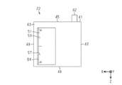
図2に示す液体収容容器22の斜視図は、容器本体41の前面43、上面45及び右側面47を示す図である。図3に示す液体収容容器22の斜視図は、容器本体41の後面44、下面46及び左側面48を示す図である。図4に示す液体収容容器22の正面図は、容器本体41の前面43を示す図である。図5に示す液体収容容器22の背面図は、容器本体41の後面44を示す図である。図6に示す液体収容容器22の平面図は、容器本体41の上面45を示す図である。図7に示す液体収容容器22の底面図は、容器本体41の下面46を示す図である。図8に示す液体収容容器22の右側面図は、容器本体41の右側面47を示す図である。図9に示す液体収容容器22の左側面図は、容器本体41の左側面48を示す図である。
The perspective view of the liquid storage container 22 shown in FIG. 2 shows the front surface 43 , upper surface 45 and right side surface 47 of the container body 41 . The perspective view of the liquid storage container 22 shown in FIG. 3 shows the rear surface 44 , the lower surface 46 and the left side surface 48 of the container body 41 . The front view of the liquid storage container 22 shown in FIG. 4 shows the front surface 43 of the container body 41 . The rear view of the liquid storage container 22 shown in FIG. 5 shows the rear surface 44 of the container body 41 . The plan view of the liquid storage container 22 shown in FIG. 6 shows the upper surface 45 of the container body 41 . The bottom view of the liquid storage container 22 shown in FIG. 7 shows the bottom surface 46 of the container body 41 . The right side view of the liquid container 22 shown in FIG. 8 shows the right side 47 of the container body 41 . The left side view of the liquid storage container 22 shown in FIG. 9 shows the left side 48 of the container body 41 .
容器本体41の前面43、後面44、上面45、下面46、右側面47及び左側面48は、それぞれ筐体12の前面13、後面、上面15、下面、右側面17及び左側面に対応する面である。容器本体41がキャリッジ23に装着された状態において、容器本体41の前面43は筐体12の前方を向く面である。容器本体41の後面44は筐体12の後方を向く面である。容器本体41の上面45は筐体12の上方を向く面である。容器本体41の下面46は筐体12の下方を向く面である。容器本体41の右側面47は筐体12の右側方を向く面である。容器本体41の左側面48は筐体12の左側方を向く面である。
The front surface 43, rear surface 44, upper surface 45, lower surface 46, right side surface 47 and left side surface 48 of the container body 41 correspond to the front surface 13, rear surface, upper surface 15, lower surface, right side 17 and left side of the housing 12, respectively. is. When the container body 41 is attached to the carriage 23 , the front surface 43 of the container body 41 faces the front of the housing 12 . A rear surface 44 of the container body 41 is a surface facing the rear of the housing 12 . An upper surface 45 of the container body 41 is a surface facing upward of the housing 12 . A lower surface 46 of the container body 41 is a surface facing downward of the housing 12 . A right side surface 47 of the container body 41 faces the right side of the housing 12 . A left side surface 48 of the container body 41 faces the left side of the housing 12 .
第1実施形態において、容器本体41の前面43及び後面44は、筐体12の前面13及び後面と同様に、幅方向X及び鉛直方向Zに広がりを有する面である。容器本体41の上面45及び下面46は、筐体12の上面15及び下面と同様に、幅方向X及び奥行方向Yに広がりを有する面である。容器本体41の右側面47及び左側面48は、筐体12の右側面17及び左側面と同様に、奥行方向Y及び鉛直方向Zに広がりを有する面である。
In the first embodiment, the front surface 43 and the rear surface 44 of the container body 41 are surfaces that spread in the width direction X and the vertical direction Z, like the front surface 13 and the rear surface of the housing 12 . The upper surface 45 and the lower surface 46 of the container body 41 are surfaces that spread in the width direction X and the depth direction Y, like the upper surface 15 and the lower surface of the housing 12 . The right side surface 47 and the left side surface 48 of the container body 41 are surfaces that spread in the depth direction Y and the vertical direction Z, like the right side surface 17 and the left side surface of the housing 12 .
注入部42は、筒状に設けられ、容器本体41の上面45から上方に向けて延びる。注入部42は、上面45において、前面43寄り且つ右側面47寄りとなる位置に設けられる。液体収容容器22は、液体を貯留する補充容器から注入部42を介して液体を補充される。補充容器は例えばボトルである。上面カバー26を開くと、液体収容容器22の注入部42が露出する。液体収容容器22は、キャリッジ23に搭載された状態で液体を補充可能とされる。注入部42は、キャリッジ23がホームポジションに位置する場合に、第2開口32から露出するように位置してもよい。こうすると、上面カバー26を開くことなく、第2開口32を介して注入部42から液体を注入できる。
The injection part 42 is provided in a cylindrical shape and extends upward from the upper surface 45 of the container body 41 . The injection part 42 is provided on the upper surface 45 at a position closer to the front surface 43 and closer to the right side surface 47 . The liquid storage container 22 is replenished with liquid through the injection part 42 from a replenishment container that stores liquid. The refill container is for example a bottle. When the top cover 26 is opened, the injection part 42 of the liquid container 22 is exposed. The liquid storage container 22 can be replenished with liquid while being mounted on the carriage 23 . The injection part 42 may be positioned so as to be exposed from the second opening 32 when the carriage 23 is positioned at the home position. In this way, the liquid can be injected from the injection part 42 through the second opening 32 without opening the top cover 26 .
容器本体41の上面45には、容器本体41内に向けて下方に凹む凹部45aが形成される。凹部45aは、上面45において、前面43寄りとなるその縁から、奥行方向Yにおいて中央よりも後面44寄りとなる位置に亘って形成される。凹部45aは、上面45において、右側面47寄りとなる位置に形成される。注入部42は、凹部45aから上方に向けて延びる。
An upper surface 45 of the container body 41 is formed with a concave portion 45 a that is recessed downward toward the inside of the container body 41 . The recessed portion 45a is formed on the upper surface 45 from the edge closer to the front surface 43 to a position closer to the rear surface 44 than the center in the depth direction Y. As shown in FIG. The concave portion 45 a is formed at a position on the upper surface 45 closer to the right side surface 47 . The injection part 42 extends upward from the recess 45a.
容器本体41の少なくとも一部分は、収容する液体の残量を視認可能な透明度を有する透明材料で形成される。この透明材料は、透明部材35を形成する材料と同一の材料でもよいし、異なる材料でもよい。容器本体41において透明材料で形成された部分を介して、容器本体41が収容する液体の残量を視認できる。容器本体41において透明材料で形成された部分は、容器本体41が収容する液体の残量を視認可能な視認部50となる。
At least a portion of the container body 41 is made of a transparent material that allows the remaining amount of liquid to be contained therein to be visually recognized. This transparent material may be the same material as the material forming the transparent member 35, or may be a different material. The remaining amount of the liquid contained in the container body 41 can be visually recognized through the portion formed of the transparent material in the container body 41 . A portion of the container body 41 made of a transparent material serves as a visual recognition portion 50 through which the remaining amount of the liquid contained in the container body 41 can be visually recognized.
視認部50は、例えばプラスチック、ガラス、セラミックなどの透明材料で形成される。筐体12の開口30を介して容器本体41の視認部50を見ることにより、容器本体41が収容する液体の残量を筐体12外から視認できる。特に、記録装置11が待機状態である場合、キャリッジ23がホームポジションに位置する場合に、開口30及び視認部50を介して容器本体41が収容する液体の残量を視認し易い。
The visual recognition part 50 is made of a transparent material such as plastic, glass, or ceramic. By viewing the visual recognition portion 50 of the container body 41 through the opening 30 of the housing 12 , the remaining amount of liquid contained in the container body 41 can be visually recognized from outside the housing 12 . In particular, when the recording apparatus 11 is in the standby state and the carriage 23 is positioned at the home position, it is easy to visually recognize the remaining amount of liquid contained in the container body 41 through the opening 30 and the visual recognition portion 50 .
開口30は、筐体12外から筐体12内に光を取り入れるための開口としても機能する。開口30を介して筐体12外から筐体12内に光が入射すると、筐体12内が照らされる。これにより、容器本体41が収容する液体の残量を視認し易くなる。特に、開口30を介して取り入れられる光が容器本体41内に入射すると、容器本体41が収容する液体の残量を一層視認し易くなる。
The opening 30 also functions as an opening for introducing light into the housing 12 from outside the housing 12 . When light enters the housing 12 from outside the housing 12 through the opening 30, the inside of the housing 12 is illuminated. This makes it easier to visually recognize the remaining amount of the liquid contained in the container body 41 . In particular, when the light introduced through the opening 30 enters the container body 41, it becomes easier to visually recognize the remaining amount of the liquid contained in the container body 41. FIG.
視認部50は、容器本体41において少なくとも1つの面に形成される。第1実施形態において、視認部50は、容器本体41の前面43及び上面45の2つの面にそれぞれ形成される。そのため、第1実施形態においては、容器本体41の前面43に設けられる視認部50を第1視認部51、容器本体41の上面45に設けられる視認部50を第2視認部52と称する。
The visual recognition part 50 is formed on at least one surface of the container body 41 . In the first embodiment, the visual recognition part 50 is formed on two surfaces, ie, the front surface 43 and the upper surface 45 of the container body 41 respectively. Therefore, in the first embodiment, the visual recognition portion 50 provided on the front surface 43 of the container body 41 is referred to as the first visual recognition portion 51 , and the visual recognition portion 50 provided on the upper surface 45 of the container main body 41 is referred to as the second visual recognition portion 52 .
第1視認部51は、容器本体41の前面43において、下面46寄り且つ左側面48寄りとなる位置に形成される。第2視認部52は、容器本体41の上面45において、前面43寄り且つ左側面48寄りとなる位置に形成される。第2視認部52は、上面45において、凹部45aと隣り合う位置に形成される。視認部50は、後面44、右側面47などに設けられてもよい。
The first visual recognition portion 51 is formed at a position near the bottom surface 46 and the left side surface 48 on the front surface 43 of the container body 41 . The second visual recognition portion 52 is formed on the upper surface 45 of the container body 41 at a position closer to the front surface 43 and closer to the left side surface 48 . The second visual recognition portion 52 is formed on the upper surface 45 at a position adjacent to the concave portion 45a. The visual recognition portion 50 may be provided on the rear surface 44, the right side surface 47, or the like.
視認部50は、容器本体41において、開口30が設けられる筐体12の面と対応する面に設けられることが好ましい。例えば、筐体12がその前面13に開口30を有する場合、視認部50は容器本体41の前面43に設けられることが好ましい。筐体12がその上面15に開口30を有する場合、視認部50は容器本体41の上面45に設けられることが好ましい。こうすると、開口30及び視認部50を介して、容器本体41が収容する液体の残量を視認し易くなる。
The visual recognition part 50 is preferably provided on the surface of the container body 41 that corresponds to the surface of the housing 12 on which the opening 30 is provided. For example, if the housing 12 has the opening 30 on its front surface 13 , the visual recognition part 50 is preferably provided on the front surface 43 of the container body 41 . If the housing 12 has the opening 30 on its upper surface 15 , the viewing portion 50 is preferably provided on the upper surface 45 of the container body 41 . This makes it easier to visually recognize the remaining amount of liquid contained in the container body 41 through the opening 30 and the visual recognition portion 50 .
視認部50は、キャリッジ23がホームポジションに位置する場合に、開口30の位置と対応するように位置することが好ましい。例えば、第1視認部51は、キャリッジ23がホームポジションに位置する場合において筐体12の前方から第1開口31を見た際に、第1開口31と重なるように位置することが好ましい。すなわち、第1視認部51は、キャリッジ23がホームポジションに位置する場合において、奥行方向Yにおいて第1開口31と重なるように位置することが好ましい。
The viewing portion 50 is preferably positioned so as to correspond to the position of the opening 30 when the carriage 23 is positioned at the home position. For example, when the carriage 23 is positioned at the home position, the first viewing portion 51 is preferably located so as to overlap the first opening 31 when the first opening 31 is viewed from the front of the housing 12 . That is, it is preferable that the first visual recognition portion 51 be positioned so as to overlap the first opening 31 in the depth direction Y when the carriage 23 is positioned at the home position.
第2視認部52は、キャリッジ23がホームポジションに位置する場合において筐体12の上方から第2開口32を見た際に、第2開口32と重なるように位置することが好ましい。すなわち、第2視認部52は、キャリッジ23がホームポジションに位置する場合において、幅方向Xにおいて第2開口32と重なるように位置することが好ましい。こうすると、容器本体41が収容する液体の残量を一層視認し易くなる。
The second visual recognition part 52 is preferably positioned so as to overlap the second opening 32 when the second opening 32 is viewed from above the housing 12 when the carriage 23 is positioned at the home position. That is, it is preferable that the second visual recognition portion 52 is positioned so as to overlap the second opening 32 in the width direction X when the carriage 23 is positioned at the home position. This makes it easier to visually recognize the remaining amount of the liquid contained in the container body 41 .
視認部50は、例えば容器本体41の右側面47に形成されてもよい。筐体12の右側面17に第3開口33が形成される場合、視認部50は、容器本体41の右側面47に形成されることが好ましい。第1実施形態において、容器本体41の右側面47に設けられる視認部50を第3視認部53と称する。第3視認部53は、例えば図2において2点鎖線で示す位置に形成される。第3視認部53は、キャリッジ23がホームポジションに位置する場合において筐体12の右側方から第3開口33を見た際に、第3開口33と重なるように位置することが好ましい。すなわち、第3視認部53は、キャリッジ23がホームポジションに位置する場合において、幅方向Xにおいて第3開口33と重なるように位置することが好ましい。
The visual recognition part 50 may be formed, for example, on the right side surface 47 of the container body 41 . When the third opening 33 is formed on the right side surface 17 of the housing 12 , the visual recognition part 50 is preferably formed on the right side surface 47 of the container body 41 . In the first embodiment, the visual recognition portion 50 provided on the right side surface 47 of the container body 41 is called a third visual recognition portion 53 . The third visual recognition portion 53 is formed, for example, at a position indicated by a two-dot chain line in FIG. The third viewing portion 53 is preferably located so as to overlap the third opening 33 when the third opening 33 is viewed from the right side of the housing 12 when the carriage 23 is at the home position. That is, it is preferable that the third visual recognition portion 53 be positioned so as to overlap the third opening 33 in the width direction X when the carriage 23 is positioned at the home position.
容器本体41は、その全体を透明材料で構成されてもよい。この場合、容器本体41全体が透明に形成されるため、容器本体41における全ての面が視認部50として機能する。こうすると、第1開口31、第2開口32及び第3開口33の何れからでも液体収容容器22が収容する液体の残量を視認できる。容器本体41の全体を透明に形成すると、開口30から入射する光が容器本体41内に到達し易くなり、容器本体41が収容する液体の残量を視認し易くなる。
The container body 41 may be entirely made of a transparent material. In this case, since the entire container body 41 is formed transparent, all surfaces of the container body 41 function as the visual recognition portion 50 . By doing so, the remaining amount of the liquid contained in the liquid container 22 can be visually recognized from any of the first opening 31 , the second opening 32 and the third opening 33 . If the entire container body 41 is made transparent, light incident from the opening 30 can easily reach the inside of the container body 41, and the remaining amount of the liquid contained in the container body 41 can be easily visually recognized.
次に、第1実施形態の液体収容容器22の作用及び効果について説明する。
(1)容器本体41の少なくとも一部分は、透明材料で形成される。そのため、容器本体41において透明材料で形成された部分を介して、容器本体41内を視認できる。容器本体41内を見ることにより、容器本体41に収容される液体を視認できる。したがって、上記第1実施形態によれば、容器本体41において透明材料で形成された部分を介して、容器本体41に収容される液体の残量を視認できる。
Next, the action and effect of the liquid storage container 22 of the first embodiment will be described.
(1) At least part of the container body 41 is made of a transparent material. Therefore, the inside of the container body 41 can be visually recognized through the portion formed of the transparent material in the container body 41 . By looking inside the container body 41, the liquid contained in the container body 41 can be visually recognized. Therefore, according to the first embodiment, the remaining amount of liquid contained in the container main body 41 can be visually recognized through the portion of the container main body 41 formed of the transparent material.
(2)筐体12外から筐体12の開口30を介して筐体12内を見ると、容器本体41の視認部50を視認できる。すなわち、筐体12の開口30を介して液体収容容器22が収容する液体の残量を筐体12外から視認できる。
(2) When the inside of the housing 12 is viewed from outside the housing 12 through the opening 30 of the housing 12, the visual recognition portion 50 of the container body 41 can be visually recognized. That is, the remaining amount of liquid contained in the liquid container 22 can be visually recognized from outside the housing 12 through the opening 30 of the housing 12 .
(第2実施形態)
次に、液体収容容器22の第2実施形態について説明する。第2実施形態においては、第1実施形態と異なる点について主として説明する。第2実施形態においては、第1実施形態と比較して、容器本体41の形状が異なる。
(Second embodiment)
Next, a second embodiment of the liquid storage container 22 will be described. In the second embodiment, differences from the first embodiment will be mainly described. In the second embodiment, the shape of the container body 41 is different from that in the first embodiment.
図10、図11、図12、図13、図14、図15及び図16に示すように、第2実施形態の容器本体41は傾斜面56を有する。すなわち、容器本体41を構成する複数の面のうち少なくとも1つの面が傾斜面56とされる。傾斜面56は、容器本体41がキャリッジ23に装着された状態において、下方から上方にかけて容器本体41の内部に向かうように傾斜する面である。すなわち、傾斜面56は、容器本体41において、上方を向く面である。傾斜面56は、容器本体41において上下に延びる。傾斜面56は、容器本体41において複数設けられてもよい。
As shown in FIGS. 10 , 11 , 12 , 13 , 14 , 15 and 16 , the container body 41 of the second embodiment has an inclined surface 56 . That is, at least one of the plurality of surfaces forming the container body 41 is the inclined surface 56 . The inclined surface 56 is a surface that slopes toward the inside of the container body 41 from below to above when the container body 41 is mounted on the carriage 23 . That is, the inclined surface 56 is a surface facing upward in the container body 41 . The inclined surface 56 extends vertically in the container body 41 . A plurality of inclined surfaces 56 may be provided on the container body 41 .
容器本体41は、前面43、後面44、上面45、下面46、右側面47、左側面48を有する。図10に示す液体収容容器22の斜視図は、容器本体41の前面43、上面45及び右側面47を示す図である。図11に示す液体収容容器22の斜視図は、容器本体41の後面44、下面46及び左側面48を示す図である。図12に示す液体収容容器22の正面図は、容器本体41の前面43を示す図である。図13に示す液体収容容器22の背面図は、容器本体41の後面44を示す図である。図14に示す液体収容容器22の平面図は、容器本体41の上面45を示す図である。図15に示す液体収容容器22の右側面図は、容器本体41の右側面47を示す図である。図16に示す液体収容容器22の左側面図は、容器本体41の左側面48を示す図である。容器本体41の下面46は、第1実施形態における容器本体41の下面46と同様に、矩形状の平坦な面とされる。
The container body 41 has a front surface 43 , a rear surface 44 , a top surface 45 , a bottom surface 46 , a right side 47 and a left side 48 . The perspective view of the liquid storage container 22 shown in FIG. 10 shows the front surface 43 , upper surface 45 and right side surface 47 of the container body 41 . The perspective view of the liquid storage container 22 shown in FIG. 11 shows the rear surface 44 , the lower surface 46 and the left side surface 48 of the container body 41 . The front view of the liquid storage container 22 shown in FIG. 12 shows the front surface 43 of the container body 41 . The rear view of the liquid storage container 22 shown in FIG. 13 is a view showing the rear surface 44 of the container body 41. As shown in FIG. The plan view of the liquid storage container 22 shown in FIG. 14 is a view showing the upper surface 45 of the container body 41. As shown in FIG. The right side view of the liquid storage container 22 shown in FIG. 15 shows the right side 47 of the container body 41 . The left side view of the liquid storage container 22 shown in FIG. 16 shows the left side 48 of the container body 41 . The lower surface 46 of the container body 41 is a rectangular flat surface, like the lower surface 46 of the container body 41 in the first embodiment.
傾斜面56は、容器本体41がキャリッジ23に装着された状態において容器本体41の前方及び上方を向く。そのため、第2実施形態において、傾斜面56は、前面43及び上面45により構成される。換言すると、傾斜面56は、前面43及び上面45を構成する。
The inclined surface 56 faces forward and upward of the container body 41 when the container body 41 is attached to the carriage 23 . Therefore, in the second embodiment, the inclined surface 56 is composed of the front surface 43 and the upper surface 45 . In other words, the inclined surface 56 constitutes the front surface 43 and the upper surface 45 .
第2実施形態における傾斜面56は、前面43と、上面45の一部分とを構成する。上面45は、幅方向X及び奥行方向Yに広がる水平な部分と、この水平な部分に対して傾斜する部分とを有する。上面45において傾斜する部分が、傾斜面56であり前面43でもある。傾斜面56は、上面45において容器本体41の前方寄りに位置する。凹部45aは、上面45において、幅方向X及び奥行方向Yに広がる水平な部分に位置する。
The inclined surface 56 in the second embodiment constitutes the front surface 43 and part of the upper surface 45 . The upper surface 45 has a horizontal portion extending in the width direction X and the depth direction Y and a portion inclined with respect to the horizontal portion. The inclined portion of the upper surface 45 is both the inclined surface 56 and the front surface 43 . The inclined surface 56 is positioned toward the front of the container body 41 on the upper surface 45 . The recessed portion 45 a is located in a horizontal portion extending in the width direction X and the depth direction Y on the upper surface 45 .
傾斜面56は、後面44、右側面47又は左側面48を構成するように設けられてもよい。傾斜面56は、後面44を構成する場合、容器本体41の後方及び上方を向く。傾斜面56は、右側面47を構成する場合、容器本体41の上方及び右側方を向く。傾斜面56は、左側面48を構成する場合、容器本体41の上方及び左側方を向く。
An angled surface 56 may be provided to define the rear surface 44 , the right side 47 or the left side 48 . The inclined surface 56 faces rearwardly and upwardly of the container body 41 when forming the rear surface 44 . When forming the right side surface 47 , the inclined surface 56 faces upward and rightward of the container body 41 . When forming the left side surface 48 , the inclined surface 56 faces upward and leftward of the container body 41 .
傾斜面56は、例えば前面43、上面45及び右側面47を構成するように設けられてもよい。この場合、傾斜面56は、容器本体41の前方、上方及び右側方を向くように傾斜する。このように、傾斜面56は、容器本体41において3つの方向を向くように傾斜する面としてもよい。傾斜面56を有する容器本体41の形状は任意に変更してよい。
The sloping surfaces 56 may be provided to form the front surface 43 , the top surface 45 and the right side surface 47 , for example. In this case, the inclined surface 56 is inclined to face forward, upward and rightward of the container body 41 . In this way, the inclined surface 56 may be a surface inclined in three directions on the container body 41 . The shape of the container body 41 having the inclined surface 56 may be changed arbitrarily.
傾斜面56は、容器本体41の前方、後方、右側方及び左側方のうちの少なくとも1つの方向と、上方とを向く面である。そのため、傾斜面56は、容器本体41に対して上方及び下方を除くその他の方向と、上方とから視認できる面である。第2実施形態において、傾斜面56は、容器本体41の前方及び上方から視認可能である。傾斜面56は、前面43、右側面47及び左側面48のうち少なくとも1つの面と、上面45とを構成することが好ましい。
The inclined surface 56 faces at least one of the front, rear, right and left sides of the container body 41 and upward. Therefore, the inclined surface 56 is a surface that can be visually recognized with respect to the container body 41 from directions other than above and below, and from above. In the second embodiment, the inclined surface 56 is visible from the front and above the container body 41 . The inclined surface 56 preferably forms at least one of the front surface 43 , the right side surface 47 and the left side surface 48 and the upper surface 45 .
傾斜面56の少なくとも一部分は、透明材料で形成される。そのため、傾斜面56には視認部50が設けられる。第2実施形態においては、傾斜面56においてその縁部分を除く領域が透明材料で形成される。これにより、傾斜面56を介して容器本体41内を視認できる。第2実施形態において、傾斜面56は前面43及び上面45を構成するため、傾斜面56に設けられる視認部50は、第1視認部51でもあり第2視認部52でもある。傾斜面56の全体を透明材料で形成してもよい。第2実施形態においては、第3視認部53を設けてもよいし設けなくともよい。
At least a portion of the inclined surface 56 is made of a transparent material. Therefore, the viewing portion 50 is provided on the inclined surface 56 . In the second embodiment, the area of the inclined surface 56 excluding the edge portion is formed of a transparent material. Thereby, the inside of the container main body 41 can be visually recognized through the inclined surface 56 . In the second embodiment, since the inclined surface 56 forms the front surface 43 and the upper surface 45 , the visual recognition portion 50 provided on the inclined surface 56 is both the first visual recognition portion 51 and the second visual recognition portion 52 . The entire inclined surface 56 may be made of a transparent material. In the second embodiment, the third visual recognition portion 53 may or may not be provided.
容器本体41が収容する液体の液面は、その液体の残量が減ることに伴って下降する。そのため、容器本体41が収容する液体の液面位置を見ると、その液体の残量を把握し易い。本明細書中において、液面位置とは、鉛直方向Zにおける液面の位置のことを指す。
The liquid level of the liquid contained in the container main body 41 descends as the remaining amount of the liquid decreases. Therefore, by looking at the level of the liquid contained in the container body 41, it is easy to grasp the remaining amount of the liquid. In this specification, the liquid level position refers to the position of the liquid level in the vertical direction Z.
容器本体41の前方から傾斜面56を見ると、傾斜面56に設けられる視認部50を介して液面位置を視認できる。これにより、例えば図12において、容器本体41が収容する液体の液面位置が傾斜面56において上方寄りに位置する場合、液体の残量が多いことを把握できる。図12において、液体の液面位置が傾斜面56において下方寄りに位置する場合、液体の残量が少ないことを把握できる。
When the inclined surface 56 is viewed from the front of the container body 41 , the liquid surface position can be visually recognized through the visual recognition portion 50 provided on the inclined surface 56 . As a result, for example, in FIG. 12, when the liquid surface position of the liquid contained in the container body 41 is located near the upper side of the inclined surface 56, it can be grasped that the remaining amount of liquid is large. In FIG. 12, when the liquid surface position of the liquid is positioned toward the lower side of the inclined surface 56, it can be understood that the remaining amount of liquid is small.
容器本体41の上方から傾斜面56を見ると、傾斜面56に設けられる視認部50を介して液面の縁を視認できる。このとき、傾斜面56において液面の縁がどの位置にあるかを見ることにより、液面位置を視認できる。例えば図14において、容器本体41が収容する液体の液面の縁が傾斜面56において容器本体41の後方寄りに位置する場合、液体の液面位置が高い位置にあることを視認できる。すなわち、液体の残量が多いことを把握できる。図14において、液体の液面の縁が傾斜面56において容器本体41の前方寄りに位置する場合、液体の液面位置が低い位置にあることを視認できる。すなわち、液体の残量が少ないことを把握できる。
When the inclined surface 56 is viewed from above the container body 41 , the edge of the liquid surface can be visually recognized through the visual recognition portion 50 provided on the inclined surface 56 . At this time, the position of the liquid surface can be visually recognized by observing the position of the edge of the liquid surface on the inclined surface 56 . For example, in FIG. 14, when the edge of the liquid surface of the liquid contained in the container body 41 is positioned toward the rear of the container body 41 on the inclined surface 56, it can be visually recognized that the liquid surface position of the liquid is at a high position. That is, it can be grasped that the remaining amount of liquid is large. In FIG. 14, when the edge of the liquid surface of the liquid is positioned toward the front of the container body 41 on the inclined surface 56, it can be visually recognized that the liquid surface position is at a low position. That is, it can be grasped that the remaining amount of liquid is small.
第2実施形態においては、容器本体41を上方から見ると、傾斜面56を視認できる。傾斜面56を見ると、傾斜面56に設けられる視認部50を介して容器本体41が収容する液体の液面位置を視認できる。これにより、容器本体41を前方から見た場合に限らず上方から見た場合でも、液体の残量を視認し易い。
In the second embodiment, the inclined surface 56 can be visually recognized when the container body 41 is viewed from above. Looking at the inclined surface 56 , the liquid surface position of the liquid contained in the container body 41 can be visually recognized through the visual recognition portion 50 provided on the inclined surface 56 . This makes it easy to visually recognize the remaining amount of liquid not only when the container body 41 is viewed from the front but also when viewed from above.
視認部50には、容器本体41が収容する液体の残量を示す目盛57が設けられてもよい。目盛57は、塗料を用いて描いたり溝を彫ったりするなどして形成される。液体の液面位置と目盛57とを比較して見ると、液体の残量を視認し易い。
The visual recognition portion 50 may be provided with a scale 57 indicating the remaining amount of the liquid contained in the container body 41 . The scale 57 is formed by drawing with paint or by carving grooves. By comparing the liquid surface position of the liquid with the scale 57, it is easy to visually recognize the remaining amount of the liquid.
上記第2実施形態によれば、(1)及び(2)の効果に加えて以下の効果を得られる。
(3)傾斜面56は、下方から上方にかけて容器本体41の内部に向かうように傾斜する。そのため、容器本体41において、傾斜面56は上方を向く。傾斜面56が上方を向くことにより、容器本体41を上方から見る場合に傾斜面56を視認できる。傾斜面56が透明材料で形成されるため、容器本体41が収容する液体の液面位置を上方から傾斜面56を介して視認できる。液体の液面位置を見ることにより、液体の残量を視認できる。このように、上記第2実施形態によれば、容器本体41に収容される液体の残量を容器本体41の上方から視認し易くできる。
According to the second embodiment, the following effects can be obtained in addition to the effects (1) and (2).
(3) The inclined surface 56 is inclined toward the inside of the container body 41 from below to above. Therefore, in the container body 41, the inclined surface 56 faces upward. Since the inclined surface 56 faces upward, the inclined surface 56 can be visually recognized when the container body 41 is viewed from above. Since the inclined surface 56 is made of a transparent material, the level of the liquid contained in the container body 41 can be visually recognized from above through the inclined surface 56 . By looking at the liquid surface position of the liquid, the remaining amount of the liquid can be visually recognized. As described above, according to the second embodiment, the remaining amount of liquid contained in the container body 41 can be easily visually recognized from above the container body 41 .
(第3実施形態)
次に、液体収容容器22の第3実施形態について説明する。第3実施形態においては、第1実施形態及び第2実施形態と異なる点について主として説明する。第3実施形態においては、第1実施形態及び第2実施形態と比較して、容器本体41の形状が異なる。
(Third embodiment)
Next, a third embodiment of the liquid storage container 22 will be described. In the third embodiment, differences from the first and second embodiments will be mainly described. In the third embodiment, the shape of the container body 41 is different compared to the first and second embodiments.
図17、図18、図19、図20、図21及び図22に示すように、第3実施形態の容器本体41は段差面59を有する。すなわち、容器本体41を構成する複数の面のうち少なくとも1つの面が段差面59とされる。段差面59は、容器本体41がキャリッジ23に装着された状態において下方から上方に向けて階段状をなす面である。段差面59は、容器本体41において上下に延びる。段差面59は、容器本体41において複数設けられてもよい。
As shown in FIGS. 17, 18, 19, 20, 21 and 22, the container body 41 of the third embodiment has a step surface 59. As shown in FIG. That is, at least one of the plurality of surfaces forming the container body 41 is the stepped surface 59 . The stepped surface 59 is a stepped surface that extends upward from below when the container body 41 is attached to the carriage 23 . The step surface 59 extends vertically in the container body 41 . A plurality of step surfaces 59 may be provided in the container body 41 .
容器本体41は、前面43、後面44、上面45、下面46、右側面47、左側面48を有する。図17に示す液体収容容器22の斜視図は、容器本体41の前面43、上面45及び右側面47を示す図である。図18に示す液体収容容器22の斜視図は、容器本体41の後面44、下面46及び左側面48を示す図である。図19に示す液体収容容器22の正面図は、容器本体41の前面43を示す図である。図20に示す液体収容容器22の平面図は、容器本体41の上面45を示す図である。図21に示す液体収容容器22の右側面図は、容器本体41の右側面47を示す図である。図22に示す液体収容容器22の左側面図は、容器本体41の左側面48を示す図である。容器本体41の後面44及び下面46は、第1実施形態における容器本体41の後面44及び下面46と同様に、矩形状の平坦な面とされる。
The container body 41 has a front surface 43 , a rear surface 44 , a top surface 45 , a bottom surface 46 , a right side 47 and a left side 48 . The perspective view of the liquid storage container 22 shown in FIG. 17 shows the front surface 43 , upper surface 45 and right side surface 47 of the container body 41 . The perspective view of the liquid container 22 shown in FIG. 18 shows the rear surface 44 , the lower surface 46 and the left side surface 48 of the container body 41 . The front view of the liquid storage container 22 shown in FIG. 19 shows the front surface 43 of the container body 41 . The plan view of the liquid storage container 22 shown in FIG. 20 shows the upper surface 45 of the container body 41. As shown in FIG. The right side view of the liquid storage container 22 shown in FIG. 21 shows the right side 47 of the container body 41 . The left side view of the liquid storage container 22 shown in FIG. 22 shows the left side 48 of the container body 41 . The rear surface 44 and the lower surface 46 of the container body 41 are rectangular flat surfaces, like the rear surface 44 and the lower surface 46 of the container body 41 in the first embodiment.
段差面59は、容器本体41がキャリッジ23に装着された状態において容器本体41の前方及び上方を向く。そのため、第3実施形態において、段差面59は、前面43及び上面45により構成される。換言すると、段差面59は、前面43及び上面45を構成する。第3実施形態の段差面59は、前面43と、上面45の一部分とを構成する。段差面59は、容器本体41において、奥行方向Yにおいて前面43の一部分と上面45の一部分とが交互に連続して並ぶことで形成される。これにより、段差面59は階段状をなす。
The step surface 59 faces forward and upward of the container body 41 when the container body 41 is attached to the carriage 23 . Therefore, in the third embodiment, the stepped surface 59 is composed of the front surface 43 and the upper surface 45 . In other words, the step surface 59 constitutes the front surface 43 and the upper surface 45 . The stepped surface 59 of the third embodiment constitutes the front surface 43 and part of the upper surface 45 . The step surface 59 is formed by alternately arranging a portion of the front surface 43 and a portion of the upper surface 45 in the depth direction Y in the container body 41 . As a result, the step surface 59 has a stepped shape.
前面43は、下方から上方に向けて順に、第1前面431、第2前面432、第3前面433、第4前面434を有する。上面45は、奥行方向Yにおいて順に、第1上面451、第2上面452、第3上面453、第4上面454を有する。
The front surface 43 has a first front surface 431, a second front surface 432, a third front surface 433, and a fourth front surface 434 in order from the bottom to the top. The top surface 45 has a first top surface 451 , a second top surface 452 , a third top surface 453 , and a fourth top surface 454 in order in the depth direction Y. As shown in FIG.
段差面59は、第1前面431、第1上面451、第2前面432、第2上面452、第3前面433、第3上面453、第4前面434によって形成される。容器本体41において第1前面431、第1上面451、第2前面432、第2上面452、第3前面433、第3上面453、第4前面434の順に並ぶことにより、段差面59は階段状をなす。第4上面454には、注入部42及び凹部45aが設けられる。
The step surface 59 is formed by a first front surface 431 , a first upper surface 451 , a second front surface 432 , a second upper surface 452 , a third front surface 433 , a third upper surface 453 and a fourth front surface 434 . By arranging the first front surface 431, the first upper surface 451, the second front surface 432, the second upper surface 452, the third front surface 433, the third upper surface 453, and the fourth front surface 434 in this order in the container body 41, the step surface 59 has a stepped shape. form. The fourth upper surface 454 is provided with the injection part 42 and the recess 45a.
段差面59は、後面44、右側面47又は左側面48を構成するように設けられてもよい。段差面59は、後面44を構成する場合、容器本体41の後方及び上方を向く。段差面59は、右側面47を構成する場合、容器本体41の上方及び右側方を向く。段差面59は、左側面48を構成する場合、容器本体41の上方及び左側方を向く。段差面59を有する容器本体41の形状は任意に変更してよい。
The step surface 59 may be provided to form the rear surface 44 , the right side surface 47 or the left side surface 48 . When forming the rear surface 44 , the stepped surface 59 faces rearwardly and upwardly of the container body 41 . When forming the right side surface 47 , the step surface 59 faces upward and to the right side of the container body 41 . When forming the left side surface 48 , the stepped surface 59 faces upward and leftward of the container body 41 . The shape of the container body 41 having the step surface 59 may be changed arbitrarily.
段差面59は、容器本体41の前方、後方、右側方及び左側方のうちの少なくとも1つの方向と、上方とを向く面である。そのため、段差面59は、容器本体41に対して上方及び下方を除くその他の方向と、上方とから視認できる面である。第3実施形態において、段差面59は、容器本体41の前方及び上方から視認可能である。段差面59は、前面43、右側面47及び左側面48のうち少なくとも1つの面と、上面45とを構成することが好ましい。
The step surface 59 is a surface facing at least one of the front, rear, right and left sides of the container body 41 and upward. Therefore, the step surface 59 is a surface that can be visually recognized from above the container body 41 as well as from directions other than above and below. In the third embodiment, the step surface 59 is visible from the front and above the container body 41 . The step surface 59 preferably forms at least one of the front surface 43 , the right side surface 47 and the left side surface 48 and the upper surface 45 .
段差面59の少なくとも一部分は、透明材料で形成される。そのため、段差面59には視認部50が設けられる。第3実施形態においては、段差面59においてその縁部分を除く領域が透明材料で形成される。例えば、段差面59において、図17、図19及び図20において2点鎖線で示す部分が透明材料で形成される。これにより、段差面59を介して容器本体41内を視認可能となる。段差面59の全体を透明材料で形成してもよい。
At least a portion of the step surface 59 is made of a transparent material. Therefore, the visual recognition portion 50 is provided on the step surface 59 . In the third embodiment, the area of the step surface 59 excluding the edge portion is formed of a transparent material. For example, on the stepped surface 59, the portions indicated by the two-dot chain lines in FIGS. 17, 19 and 20 are made of a transparent material. As a result, the inside of the container body 41 can be visually recognized through the step surface 59 . The entire step surface 59 may be made of a transparent material.
視認部50は、段差面59において、第1前面431、第1上面451、第2前面432、第2上面452、第3前面433、第3上面453、第4前面434に亘って設けられる。第1前面431、第2前面432、第3前面433及び第4前面434に設けられる視認部50は、第1視認部51である。第1上面451、第2上面452及び第3上面453に設けられる視認部50は、第2視認部52である。そのため、視認部50は、段差面59において第1視認部51と第2視認部52とが交互に並ぶように形成される。第4上面454に視認部50を設けてもよい。第3実施形態においては、第3視認部53を設けてもよいし設けなくともよい。
The visual recognition part 50 is provided over the first front surface 431 , the first upper surface 451 , the second front surface 432 , the second upper surface 452 , the third front surface 433 , the third upper surface 453 , and the fourth front surface 434 on the step surface 59 . The visual recognition part 50 provided on the first front surface 431 , the second front surface 432 , the third front surface 433 and the fourth front surface 434 is the first visual recognition part 51 . The visible portions 50 provided on the first upper surface 451 , the second upper surface 452 and the third upper surface 453 are the second visible portions 52 . Therefore, the visual recognition portion 50 is formed so that the first visual recognition portions 51 and the second visual recognition portions 52 are alternately arranged on the step surface 59 . The visual recognition portion 50 may be provided on the fourth upper surface 454 . In the third embodiment, the third visual recognition portion 53 may or may not be provided.
図19に示すように、容器本体41の前方から段差面59を見ると、第1前面431、第2前面432、第3前面433及び第4前面434が下方から上方に向けて連続して並ぶように見える。そのため、第1前面431、第2前面432、第3前面433及び第4前面434にそれぞれ設けられる第1視認部51が上下に連続して並ぶように見える。このとき、第1視認部51を介して、容器本体41が収容する液体の液面位置を視認できる。これにより、図19において、容器本体41が収容する液体の液面位置が段差面59において上方寄りに位置する場合、液体の残量が多いことを把握できる。図19において、液体の液面位置が段差面59において下方寄りに位置する場合、液体の残量が少ないことを把握できる。
As shown in FIG. 19, when the stepped surface 59 is viewed from the front of the container body 41, the first front surface 431, the second front surface 432, the third front surface 433, and the fourth front surface 434 are continuously arranged from the bottom to the top. looks like. Therefore, the first visual recognition portions 51 respectively provided on the first front surface 431, the second front surface 432, the third front surface 433, and the fourth front surface 434 appear to be continuously arranged vertically. At this time, the liquid surface position of the liquid contained in the container body 41 can be visually recognized via the first visual recognition portion 51 . Accordingly, in FIG. 19, when the liquid surface position of the liquid contained in the container main body 41 is positioned near the upper side of the step surface 59, it can be grasped that the remaining amount of liquid is large. In FIG. 19, when the liquid surface position of the liquid is positioned toward the lower side of the step surface 59, it can be grasped that the remaining amount of liquid is small.
図20に示すように、容器本体41の上方から段差面59を見ると、第1上面451、第2上面452、第3上面453及び第4上面454が奥行方向Yにおいて連続して並ぶように見える。そのため、第1上面451、第2上面452及び第3上面453にそれぞれ設けられる第2視認部52が奥行方向Yに連続して並ぶように見える。このとき、容器本体41が収容する液体の残量に応じて、第2視認部52を介して容器本体41内を見たときの液体の見え方が異なる。
As shown in FIG. 20, when the stepped surface 59 is viewed from above the container body 41, the first upper surface 451, the second upper surface 452, the third upper surface 453, and the fourth upper surface 454 are arranged continuously in the depth direction Y. appear. Therefore, the second visual recognition portions 52 provided on the first upper surface 451, the second upper surface 452, and the third upper surface 453 appear to be continuously arranged in the depth direction Y. As shown in FIG. At this time, the appearance of the liquid when the inside of the container body 41 is viewed through the second visual recognition portion 52 varies depending on the remaining amount of the liquid contained in the container body 41 .
容器本体41が収容する液体の残量が多い場合、例えば液面位置が第3上面453よりも高い位置にある場合、第1上面451、第2上面452、第3上面453と、液面位置との鉛直方向Zにおける距離がそれぞれほぼ同じとなる。そのため、第1上面451、第2上面452、第3上面453の第2視認部52を介して容器本体41内を見たときの液体の見え方が一様となる。すなわち、第2視認部52を介して容器本体41内を見たときの液体の見え方が一様となる場合に、容器本体41において液面位置が高い位置にあることを視認できる。
When the remaining amount of the liquid contained in the container body 41 is large, for example, when the liquid level is higher than the third upper surface 453, the first upper surface 451, the second upper surface 452, the third upper surface 453, and the liquid surface position are substantially the same in the vertical direction Z. Therefore, when the inside of the container body 41 is viewed through the second visual recognition portion 52 of the first upper surface 451, the second upper surface 452, and the third upper surface 453, the appearance of the liquid becomes uniform. That is, when the appearance of the liquid when viewing the inside of the container body 41 through the second visual recognition portion 52 is uniform, it is possible to visually recognize that the liquid level is at a high position in the container body 41 .
容器本体41が収容する液体の残量が少ない場合、例えば液面位置が第1上面451よりも低い位置にある場合、第1上面451、第2上面452、第3上面453と、液面位置との鉛直方向Zにおける距離がそれぞれ異なる。具体的には、鉛直方向Zにおいて、第1上面451と液面位置との距離は、第2上面452と液面位置との距離よりも短くなる。鉛直方向Zにおいて、第2上面452と液面位置との距離は、第3上面453と液面位置との距離よりも短くなる。
When the remaining amount of the liquid contained in the container body 41 is small, for example, when the liquid surface position is lower than the first upper surface 451, the first upper surface 451, the second upper surface 452, the third upper surface 453, and the liquid surface position are different from each other in the vertical direction Z. Specifically, in the vertical direction Z, the distance between the first upper surface 451 and the liquid level position is shorter than the distance between the second upper surface 452 and the liquid level position. In the vertical direction Z, the distance between the second upper surface 452 and the liquid level position is shorter than the distance between the third upper surface 453 and the liquid level position.
通常、第2視認部52と液面位置との距離が長くなるほど、第2視認部52を介して容器本体41内を見たときの液体の視認性が低下する。そのため、液体の残量が少ない場合、第1上面451の第2視認部52を介する液体の視認性は高い一方で、第3上面453の第2視認部52を介する液体の視認性は低くなる。すなわち、液体の残量が少ない場合、第2視認部52を介して視認される液体の視認性が奥行方向Yに向かうにつれて低くなる。このようにして、容器本体41において液面位置が低い位置にあることを視認できる。
Normally, the longer the distance between the second visual recognition portion 52 and the liquid surface position, the lower the visibility of the liquid when viewing the inside of the container body 41 through the second visual recognition portion 52 . Therefore, when the remaining amount of the liquid is small, the visibility of the liquid through the second visual recognition portion 52 of the first upper surface 451 is high, but the visibility of the liquid through the second visual recognition portion 52 of the third upper surface 453 is low. . That is, when the remaining amount of the liquid is small, the visibility of the liquid visually recognized through the second visual recognition portion 52 decreases as it goes in the depth direction Y. As shown in FIG. In this way, it is possible to visually recognize that the liquid level is at a low position in the container body 41 .
上述したように、第2視認部52を介して容器本体41内を見たときの液体の見え方の違いによって、液体の液面位置を視認できる。すなわち、容器本体41を前方から見た場合に限らず上方から見た場合でも、段差面59を介して液体の液面位置を視認できる。
As described above, the liquid surface position of the liquid can be visually recognized by the difference in appearance of the liquid when the inside of the container body 41 is viewed through the second visual recognition portion 52 . That is, the liquid surface position of the liquid can be visually recognized through the stepped surface 59 not only when the container body 41 is viewed from the front but also when viewed from above.
上記第3実施形態によれば、(1)及び(2)の効果に加えて以下の効果を得られる。
(4)段差面59が下方から上方にかけて階段状をなすため、上方から容器本体41を見る場合に段差面59を視認できる。段差面59が透明材料で形成されることにより、容器本体41が収容する液体の液面位置を上方から段差面59を介して視認できる。このように、上記第3実施形態によれば、容器本体41に収容される液体の残量を視認し易くできる。
According to the third embodiment, the following effects can be obtained in addition to the effects (1) and (2).
(4) Since the step surface 59 has a stepped shape from the bottom to the top, the step surface 59 can be visually recognized when the container body 41 is viewed from above. Since the step surface 59 is made of a transparent material, the level of the liquid contained in the container body 41 can be visually recognized from above through the step surface 59 . As described above, according to the third embodiment, it is possible to easily visually recognize the remaining amount of the liquid contained in the container body 41 .
(第4実施形態)
次に、液体収容容器22の第4実施形態について示す。第4実施形態においては、第1実施形態から第3実施形態と異なる点について主として説明する。
(Fourth embodiment)
Next, a fourth embodiment of the liquid storage container 22 will be described. In the fourth embodiment, differences from the first to third embodiments will be mainly described.
図23、図24、図25、図26、図27及び図28に示すように、第4実施形態の容器本体41は柱61を有する。柱61は、容器本体41内に位置し、容器本体41がキャリッジ23に装着された状態において上下に延びるように設けられる。第4実施形態において、柱61は円錐台状に形成される。柱61は、円錐台状に限らず角錐台状でもよい。柱61は、円錐状、角錐状でもよいし、円柱状、角柱状でもよい。柱61の形状は任意に変更してよい。
As shown in FIGS. 23, 24, 25, 26, 27 and 28, the container body 41 of the fourth embodiment has columns 61. As shown in FIGS. The column 61 is positioned inside the container body 41 and provided to extend vertically when the container body 41 is attached to the carriage 23 . In the fourth embodiment, the post 61 is shaped like a truncated cone. The pillar 61 is not limited to a truncated cone shape, and may be a truncated pyramid shape. The pillar 61 may be conical, pyramidal, cylindrical, or prismatic. The shape of the pillar 61 may be changed arbitrarily.
柱61は、容器本体41の内底面から上方に向けて延びる。第4実施形態の柱61は、容器本体41の下面46の一部が容器本体41内に向けて凹むようにして形成される。柱61は、視認部50を介して視認可能な位置に位置する。第4実施形態において、柱61は、容器本体41内において、前面43寄り且つ左側面48寄りに位置する。柱61は、奥行方向Yにおいて第1視認部51と重なるように位置する。すなわち、柱61は、容器本体41を前方から見た場合に第1視認部51と重なるように位置する。こうすると、容器本体41を前方から見た場合に第1視認部51を介して柱61を視認できる。
The column 61 extends upward from the inner bottom surface of the container body 41 . The column 61 of the fourth embodiment is formed such that a portion of the lower surface 46 of the container body 41 is recessed toward the interior of the container body 41 . The pillar 61 is located at a position that can be visually recognized through the visual recognition portion 50 . In the fourth embodiment, the column 61 is positioned closer to the front surface 43 and closer to the left side surface 48 inside the container body 41 . The pillar 61 is positioned so as to overlap the first visual recognition portion 51 in the depth direction Y. As shown in FIG. That is, the column 61 is positioned so as to overlap the first visual recognition portion 51 when the container body 41 is viewed from the front. In this way, when the container body 41 is viewed from the front, the columns 61 can be visually recognized through the first visual recognition portion 51 .
柱61は鉛直方向Zにおいて第2視認部52と重なるように位置する。すなわち、柱61は、容器本体41を上方から見た場合に第2視認部52と重なるように位置する。こうすると、容器本体41を上方から見た場合に第2視認部52を介して柱61を視認できる。
The pillar 61 is positioned so as to overlap the second visual recognition portion 52 in the vertical direction Z. As shown in FIG. That is, the column 61 is positioned so as to overlap the second visual recognition portion 52 when the container body 41 is viewed from above. In this way, when the container body 41 is viewed from above, the column 61 can be visually recognized through the second visual recognition portion 52 .
柱61は、第1視認部51及び第2視認部52を介してその外形が把握できる程度の大きさであることが好ましい。換言すると、第1視認部51、第2視認部52は、柱61の外形を把握できる程度の大きさであることが好ましい。第3実施形態における第1視認部51は、前面43において鉛直方向Zに延びる長方形状をなす。第2視認部52は、上面45において正方形状をなす。第4実施形態においては、第3視認部53を設けてもよいし設けなくともよい。
It is preferable that the pillar 61 has a size that allows its outer shape to be grasped through the first visual recognition portion 51 and the second visual recognition portion 52 . In other words, it is preferable that the first visual recognition portion 51 and the second visual recognition portion 52 have a size that allows the outline of the column 61 to be grasped. The first visual recognition portion 51 in the third embodiment has a rectangular shape extending in the vertical direction Z on the front surface 43 . The second visual recognition portion 52 has a square shape on the upper surface 45 . In the fourth embodiment, the third visual recognition portion 53 may or may not be provided.
視認部50を介して容器本体41内を見ると、液体と柱61とを視認できる。このとき、容器本体41内において、柱61の一部分が液体の液面から突出している。液面から突出する柱61の突出量は、液体の液面位置によって変わる。そのため、液体の液面から突出する柱61の突出量を見ると、液体の残量を視認し易い。
When the inside of the container body 41 is viewed through the viewing portion 50, the liquid and the column 61 can be viewed. At this time, a part of the column 61 protrudes from the surface of the liquid inside the container body 41 . The amount of protrusion of the columns 61 protruding from the liquid surface varies depending on the position of the liquid surface. Therefore, it is easy to visually recognize the remaining amount of the liquid by looking at the protrusion amount of the column 61 protruding from the liquid surface of the liquid.
容器本体41を前方から見ると、第1視認部51を介して液体と柱61とを視認できる。第1視認部51を介して視認される柱61の突出量が小さい場合、すなわち柱61の上端部分である先端部分だけが液面から突出する場合、液体の液面位置が高いことを視認できる。これにより、液体の残量が多いことを視認できる。
When viewing the container body 41 from the front, the liquid and the column 61 can be visually recognized through the first visual recognition portion 51 . When the amount of protrusion of the column 61 visually recognized through the first visual recognition portion 51 is small, that is, when only the top end portion of the column 61 protrudes from the liquid surface, it is possible to visually recognize that the liquid level is high. . This makes it possible to visually recognize that there is a large amount of liquid remaining.
第1視認部51を介して視認される柱61の突出量が大きい場合、すなわち柱61の先端とは反対側の基端寄りとなる部分が液面から突出する場合、液体の液面位置が低いことを視認できる。これにより、液体の残量が少ないことを視認できる。このように、容器本体41内に柱61を設けることによって、液体の残量を視認し易くできる。
When the amount of protrusion of the column 61 visually recognized through the first visual recognition portion 51 is large, that is, when the portion closer to the base end on the side opposite to the tip of the column 61 protrudes from the liquid surface, the position of the liquid surface changes. You can see that it's low. This makes it possible to visually recognize that the remaining amount of liquid is small. By providing the pillars 61 in the container body 41 in this way, it is possible to easily visually recognize the remaining amount of the liquid.
柱61は錐台状又は錐体状に形成するとよい。こうすると、容器本体41を上方から見る場合においても、液体の残量を視認し易くなる。容器本体41を上方から見ると、第2視認部52を介して液体と柱61とを視認できる。液体の残量が多い場合、すなわち液面位置が高い場合、柱61は、径が小さいその先端部分だけが液面から突出する。そのため、第2視認部52を介して視認される柱61の面積量が小さい。これにより、柱61の突出量が小さいことを視認できる。
The pillars 61 are preferably formed in the shape of a frustum or pyramid. This makes it easier to visually recognize the remaining amount of liquid even when the container body 41 is viewed from above. When the container body 41 is viewed from above, the liquid and the column 61 can be visually recognized through the second visual recognition portion 52 . When the remaining amount of liquid is large, that is, when the liquid level is high, only the tips of the pillars 61 with small diameters protrude from the liquid level. Therefore, the amount of area of the column 61 visually recognized through the second visual recognition part 52 is small. Thereby, it can be visually recognized that the amount of protrusion of the column 61 is small.
液体の残量が少ない場合、すなわち液面位置が低い場合、柱61は、径が大きいその基端寄りの部分が液面から突出する。そのため、第2視認部52を介して視認される柱61の面積量が大きい。これにより、柱61の突出量が大きいことを視認できる。第2視認部52を介して、液面から突出する柱61の突出量を見ることにより、液面位置を視認できる。液面位置を見ることによって、液体の残量を把握できる。
When the remaining amount of liquid is small, that is, when the liquid level is low, the portion of the column 61 near the base end, which has a large diameter, protrudes from the liquid level. Therefore, the amount of area of the column 61 visually recognized through the second visual recognition part 52 is large. Thereby, it can be visually recognized that the amount of protrusion of the column 61 is large. The position of the liquid surface can be visually recognized by observing the projection amount of the column 61 projecting from the liquid surface through the second visual recognition portion 52 . By looking at the liquid surface position, the remaining amount of the liquid can be grasped.
視認部50を介して容器本体41内を見たときに、柱61が液面から突出していない場合がある。この場合、柱61の先端よりも液面位置の方が高い位置にある。そのため、柱61が液面から突出していない場合、液体の残量が多いことを視認できる。
When the inside of the container main body 41 is viewed through the viewing portion 50, the column 61 may not protrude from the liquid surface. In this case, the liquid surface position is higher than the tip of the column 61 . Therefore, when the column 61 does not protrude from the liquid surface, it is possible to visually recognize that there is a large amount of liquid remaining.
柱61の内部に例えばLEDである発光体62を配置してもよい。こうすると、発光体62の発光により柱61がその内部から照らされることによって、柱61の突出量を視認し易くなる。
A light emitter 62 , for example an LED, may be arranged inside the column 61 . In this way, the column 61 is illuminated from the inside by the light emitted from the light emitter 62, so that the amount of protrusion of the column 61 can be easily recognized.
柱61には、目盛57が設けられてもよい。目盛57は、柱61の周面に沿って形成されるとよい。柱61に目盛57を設けることにより、液体の残量を視認し易くなる。
上記第4実施形態によれば、(1)及び(2)の効果に加えて以下の効果を得られる。
A scale 57 may be provided on the pillar 61 . The scale 57 is preferably formed along the peripheral surface of the pillar 61 . By providing the scale 57 on the column 61, it becomes easier to visually recognize the remaining amount of the liquid.
According to the fourth embodiment, the following effects can be obtained in addition to the effects (1) and (2).
(5)視認部50を介して容器本体41内を見ると、容器本体41が収容する液体の液面から突出する柱61の突出量を視認できる。柱61の突出量が大きい場合、液体の残量が少ないことを視認できる。柱61の突出量が小さい場合、液体の残量が多いことを視認できる。このように、柱61を設けることによって、液体の残量を視認し易くできる。
(5) When the inside of the container body 41 is viewed through the viewing portion 50, the projection amount of the columns 61 projecting from the liquid surface of the liquid contained in the container body 41 can be visually recognized. When the amount of protrusion of the column 61 is large, it can be visually recognized that the remaining amount of liquid is small. When the amount of protrusion of the column 61 is small, it can be visually recognized that there is a large amount of remaining liquid. By providing the pillars 61 in this way, it is possible to easily visually recognize the remaining amount of the liquid.
(第5実施形態)
次に、液体収容容器22の第5実施形態について示す。第5実施形態においては、第1実施形態から第4実施形態と異なる点について主として説明する。
(Fifth embodiment)
Next, a fifth embodiment of the liquid storage container 22 will be described. In the fifth embodiment, differences from the first to fourth embodiments will be mainly described.
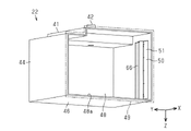
図29、図30、図31及び図32に示すように、第5実施形態の容器本体41は仕切板64を有する。仕切板64は、容器本体41内に位置し、容器本体41がキャリッジ23に装着された状態において上下に延びるように設けられる。仕切板64は、容器本体41内を仕切る。仕切板64は、容器本体41の前方から後方にかけて、下方から上方に向かうように延びる。そのため、仕切板64は、容器本体41の前面43、後面44、上面45、下面46に対して傾斜している。仕切板64は、その表面が上方を向くように傾斜しているともいえる。
As shown in FIGS. 29, 30, 31 and 32, the container body 41 of the fifth embodiment has partition plates 64. As shown in FIGS. The partition plate 64 is positioned inside the container body 41 and is provided so as to extend vertically when the container body 41 is attached to the carriage 23 . The partition plate 64 partitions the interior of the container body 41 . The partition plate 64 extends upward from the front to the rear of the container body 41 . Therefore, the partition plate 64 is inclined with respect to the front surface 43 , rear surface 44 , upper surface 45 and lower surface 46 of the container body 41 . It can be said that the partition plate 64 is inclined so that its surface faces upward.
仕切板64は、容器本体41の内底面から上方に向けて延びる。仕切板64は、視認部50を介して視認可能な位置に位置する。第5実施形態において、仕切板64は、容器本体41内において左側面48寄りに位置する。
The partition plate 64 extends upward from the inner bottom surface of the container body 41 . The partition plate 64 is positioned at a position that can be visually recognized through the visual recognition portion 50 . In the fifth embodiment, the partition plate 64 is positioned closer to the left side surface 48 inside the container body 41 .
仕切板64は、奥行方向Yにおいて第1視認部51と重なるように位置する。すなわち、仕切板64は、容器本体41を前方から見た場合に第1視認部51と重なるように位置する。こうすると、容器本体41を前方から見た場合に第1視認部51を介して仕切板64を視認できる。
The partition plate 64 is positioned so as to overlap the first visual recognition portion 51 in the depth direction Y. As shown in FIG. That is, the partition plate 64 is positioned so as to overlap the first visual recognition portion 51 when the container body 41 is viewed from the front. By doing so, the partition plate 64 can be visually recognized through the first visual recognition portion 51 when the container body 41 is viewed from the front.
仕切板64は鉛直方向Zにおいて第2視認部52と重なるように位置する。すなわち、仕切板64は、容器本体41を上方から見た場合に第2視認部52と重なるように位置する。こうすると、容器本体41を上方から見た場合に第2視認部52を介して仕切板64を視認できる。
The partition plate 64 is positioned so as to overlap the second visual recognition portion 52 in the vertical direction Z. As shown in FIG. That is, the partition plate 64 is positioned so as to overlap the second visual recognition portion 52 when the container body 41 is viewed from above. In this way, the partition plate 64 can be visually recognized through the second visual recognition portion 52 when the container body 41 is viewed from above.
第5実施形態における第1視認部51は、前面43において鉛直方向Zに延びる長方形状をなす。第2視認部52は、上面45において奥行方向Yに延びる長方形状をなす。第5実施形態においては、第3視認部53を設けてもよいし設けなくともよい。
The first visual recognition portion 51 in the fifth embodiment has a rectangular shape extending in the vertical direction Z on the front surface 43 . The second visual recognition portion 52 has a rectangular shape extending in the depth direction Y on the upper surface 45 . In the fifth embodiment, the third visual recognition portion 53 may or may not be provided.
視認部50を介して容器本体41内を見ると、液体と仕切板64とを視認できる。このとき、容器本体41内において、仕切板64の一部分が液体の液面から突出している。液面から突出する仕切板64の突出量は、その液面位置によって変わる。そのため、液体の液面から突出する仕切板64の突出量を見ると、液体の残量を視認し易い。
When the inside of the container body 41 is viewed through the viewing portion 50, the liquid and the partition plate 64 can be viewed. At this time, a part of the partition plate 64 protrudes from the liquid surface in the container main body 41 . The amount of protrusion of the partition plate 64 that protrudes from the liquid surface varies depending on the position of the liquid surface. Therefore, it is easy to visually recognize the remaining amount of the liquid by looking at the amount of protrusion of the partition plate 64 that protrudes from the surface of the liquid.
容器本体41を前方から見ると、第1視認部51を介して液体と仕切板64とを視認できる。第1視認部51を介して視認される仕切板64の突出量が小さい場合、液体の液面位置が高いことを視認できる。これにより、液体の残量が多いことを視認できる。
When viewing the container body 41 from the front, the liquid and the partition plate 64 can be visually recognized through the first visual recognition portion 51 . When the protrusion amount of the partition plate 64 visually recognized through the first visual recognition part 51 is small, it can be visually recognized that the liquid surface position of the liquid is high. This makes it possible to visually recognize that there is a large amount of liquid remaining.
第1視認部51を介して視認される仕切板64の突出量が大きい場合、液体の液面位置が低いことを視認できる。これにより、液体の残量が少ないことを視認できる。このように、容器本体41内に仕切板64を設けることによって、液体の残量を視認し易くできる。すなわち、仕切板64は、第4実施形態における柱61と同様に、液体の残量を視認し易くするための部材である。
When the protrusion amount of the partition plate 64 visually recognized through the first visual recognition part 51 is large, it is possible to visually recognize that the liquid level is low. This makes it possible to visually recognize that the remaining amount of liquid is small. By providing the partition plate 64 in the container main body 41 in this way, it is possible to easily visually recognize the remaining amount of the liquid. That is, the partition plate 64 is a member for making it easy to visually recognize the remaining amount of liquid, like the column 61 in the fourth embodiment.
容器本体41を上方から見ると、第2視認部52を介して液体と仕切板64とを視認できる。このとき、仕切板64の表面が上方を向くため、仕切板64上において液体の縁を視認できる。仕切板64上において液面の縁がどの位置にあるかを見ることにより、液面位置を視認できる。換言すると、仕切板64上において液体の縁がどの位置にあるかを見ることにより、液面から突出する仕切板64の突出量を視認できる。
When the container body 41 is viewed from above, the liquid and the partition plate 64 can be visually recognized through the second visual recognition portion 52 . At this time, since the surface of the partition plate 64 faces upward, the edge of the liquid can be visually recognized on the partition plate 64 . The position of the liquid surface can be visually recognized by observing the position of the edge of the liquid surface on the partition plate 64 . In other words, by seeing where the edge of the liquid is on the partition plate 64, the amount of protrusion of the partition plate 64 from the liquid surface can be visually recognized.
図32において、容器本体41が収容する液体の液面の縁が仕切板64上において容器本体41の後方寄りに位置する場合、液体の液面位置が高い位置にあることを視認できる。このとき、液面から突出する仕切板64の突出量が少ないことを視認できる。すなわち、液体の残量が多いことを把握できる。
In FIG. 32, when the edge of the liquid surface of the liquid contained in the container body 41 is located on the partition plate 64 toward the rear of the container body 41, it can be visually recognized that the liquid surface position of the liquid is at a high position. At this time, it can be visually recognized that the amount of protrusion of the partition plate 64 protruding from the liquid surface is small. That is, it can be grasped that the remaining amount of liquid is large.
図32において、液体の液面の縁が仕切板64上において容器本体41の前方寄りに位置する場合、液体の液面位置が低い位置にあることを視認できる。このとき、液面から突出する仕切板64の突出量が多いことを視認できる。すなわち、液体の残量が少ないことを把握できる。
In FIG. 32, when the edge of the liquid surface is located on the partition plate 64 toward the front of the container body 41, it can be visually recognized that the liquid surface position is at a low position. At this time, it can be visually recognized that the amount of protrusion of the partition plate 64 protruding from the liquid surface is large. That is, it can be grasped that the remaining amount of liquid is small.
仕切板64には、目盛57が設けられてもよい。仕切板64に目盛57を設けると、液体の残量を視認し易くなる。
第5実施形態によれば、(1)及び(2)の効果に加えて以下の効果を得られる。
A scale 57 may be provided on the partition plate 64 . If the partition plate 64 is provided with a scale 57, it becomes easier to visually recognize the remaining amount of the liquid.
According to the fifth embodiment, the following effects can be obtained in addition to the effects (1) and (2).
(6)視認部50を介して容器本体41内を見ると、容器本体41が収容する液体の液面から突出する仕切板の突出量を視認できる。仕切板の突出量が大きい場合、液体の残量が少ないことを視認できる。仕切板の突出量が小さい場合、液体の残量が多いことを視認できる。このように、仕切板を設けることによって、液体の残量を視認し易くできる。
(6) When the inside of the container body 41 is viewed through the viewing portion 50, the protrusion amount of the partition plate protruding from the liquid surface of the liquid contained in the container body 41 can be visually recognized. When the protruding amount of the partition plate is large, it can be visually recognized that the remaining amount of liquid is small. When the protrusion amount of the partition plate is small, it is possible to visually recognize that there is a large amount of remaining liquid. By providing the partition plate in this way, it is possible to easily visually recognize the remaining amount of the liquid.
(第6実施形態)
次に、液体収容容器22の第6実施形態について説明する。第6実施形態においては、第1実施形態から第5実施形態と異なる点について主として説明する。
(Sixth embodiment)
Next, a sixth embodiment of the liquid storage container 22 will be described. In the sixth embodiment, differences from the first to fifth embodiments will be mainly described.
図33、図34、図35及び図36に示すように、第6実施形態の容器本体41は仕切板66を有する。仕切板66は、容器本体41内に位置し、容器本体41がキャリッジ23に装着された状態において上下に延びるように設けられる。仕切板66は、第1視認部51を介して視認可能な位置に位置する。仕切板66は、奥行方向Yにおいて第1視認部51と重なるように位置する。すなわち、仕切板66は、容器本体41を前方から見た場合に第1視認部51と重なるように位置する。こうすると、容器本体41を前方から見た場合に第1視認部51を介して仕切板66を視認できる。
As shown in FIGS. 33, 34, 35 and 36, the container body 41 of the sixth embodiment has partition plates 66. As shown in FIGS. The partition plate 66 is positioned inside the container body 41 and is provided so as to extend vertically when the container body 41 is attached to the carriage 23 . The partition plate 66 is located at a position visible through the first visual recognition portion 51 . The partition plate 66 is positioned so as to overlap the first visual recognition portion 51 in the depth direction Y. As shown in FIG. That is, the partition plate 66 is positioned so as to overlap the first visual recognition portion 51 when the container body 41 is viewed from the front. By doing so, the partition plate 66 can be visually recognized through the first visual recognition portion 51 when the container body 41 is viewed from the front.
第6実施形態の仕切板66は、第1視認部51と一体的に形成される。そのため、仕切板66は、第1視認部51と同様に、ガラス、プラスチック、セラミックなどの透明材料で形成される。第6実施形態においては、第2視認部52及び第3視認部53を設けてもよいし設けなくともよい。
The partition plate 66 of the sixth embodiment is formed integrally with the first visual recognition portion 51 . Therefore, the partition plate 66 is made of a transparent material such as glass, plastic, or ceramic, like the first visual recognition portion 51 . In the sixth embodiment, the second visual recognition portion 52 and the third visual recognition portion 53 may or may not be provided.
図37及び図38に示すように、第1視認部51は、容器本体41の前面43を構成する表面67と、その反対側の裏面68とを有する。仕切板66は、第1視認部51の裏面68からアーチ状をなすように湾曲して延びる。図37は、図35のC-C’部分及び図36のD-D’部分における、図35のA-A切断部端面図である。図38は、図35のC-C’部分及び図36のD-D’部分における、図35のB-B切断部端面図である。
As shown in FIGS. 37 and 38, the first visual recognition portion 51 has a front surface 67 forming the front surface 43 of the container body 41 and a rear surface 68 on the opposite side. The partition plate 66 extends from the back surface 68 of the first visual recognition portion 51 so as to be curved in an arch shape. 37 is an end view of section AA of FIG. 35 at section C-C' of FIG. 35 and section D-D' of FIG. 36; FIG. 38 is an end view of section BB of FIG. 35 at section C-C' of FIG. 35 and section D-D' of FIG.
仕切板66は、第1視認部51の裏面68において鉛直方向Zに延びる。鉛直方向Zにおいて、仕切板66の長さは、第1視認部51の長さと同等である。仕切板66は、幅方向Xにおいてアーチ状をなす。仕切板66は、容器本体41の上方又は下方から見た場合において半円状をなすように湾曲する。仕切板66は、第1視認部51の裏面68において、幅方向Xの中央寄りに位置する。そのため、幅方向Xにおいて、仕切板66の長さは、第1視認部51の長さよりも短い。
The partition plate 66 extends in the vertical direction Z on the rear surface 68 of the first visual recognition portion 51 . In the vertical direction Z, the length of the partition plate 66 is the same as the length of the first visual recognition portion 51 . The partition plate 66 has an arch shape in the width direction X. As shown in FIG. The partition plate 66 curves into a semicircular shape when viewed from above or below the container body 41 . The partition plate 66 is positioned near the center in the width direction X on the rear surface 68 of the first visual recognition portion 51 . Therefore, in the width direction X, the length of the partition plate 66 is shorter than the length of the first visual recognition portion 51 .
上下に延びる仕切板66の上端及び下端は開放されている。すなわち、第1視認部51及び仕切板66は、容器本体41内において、上下に延びる筒形状を形成する。第1視認部51及び仕切板66によって形成される空間Sには、容器本体41が収容する液体が流れる。この空間Sは容器本体41内の空間の一部である。そのため、仕切板66は容器本体41内を仕切る。
The upper and lower ends of the vertically extending partition plate 66 are open. That is, the first visual recognition part 51 and the partition plate 66 form a cylindrical shape extending vertically inside the container body 41 . The liquid contained in the container body 41 flows through the space S formed by the first visual recognition portion 51 and the partition plate 66 . This space S is part of the space within the container body 41 . Therefore, the partition plate 66 partitions the interior of the container body 41 .
視認部50を介して容器本体41内を見ると、液体と仕切板66とを視認できる。このとき、容器本体41内において、仕切板66の一部分が液体の液面から突出している。液面から突出する仕切板66の突出量は、その液面位置によって変わる。そのため、液体の液面から突出する仕切板66の突出量を見ると、液体の残量を視認し易い。
When the inside of the container body 41 is viewed through the viewing portion 50, the liquid and the partition plate 66 can be viewed. At this time, a part of the partition plate 66 protrudes from the surface of the liquid inside the container main body 41 . The amount of protrusion of the partition plate 66 protruding from the liquid surface varies depending on the position of the liquid surface. Therefore, it is easy to visually recognize the remaining amount of the liquid by looking at the amount of protrusion of the partition plate 66 that protrudes from the liquid surface.
仕切板66において空間Sに面するその内周面69に、例えばシボ加工を施してもよい。シボ加工を施した透明材料の表面では、光が反射され易くなる。仕切板66の内周面69においては、シボ加工を施すことによって、その透明度が低下する。これにより、仕切板66の内周面69は、光を反射し易くなる。
The inner peripheral surface 69 of the partition plate 66 facing the space S may be textured, for example. Light is easily reflected on the surface of the transparent material that has undergone texturing. The transparency of the inner peripheral surface 69 of the partition plate 66 is reduced by texturing. Thereby, the inner peripheral surface 69 of the partition plate 66 becomes easy to reflect light.
図33、図34、図35、図36、図37及び図38に示すように、仕切板66は、容器本体41内において、視認部50が設けられる面、すなわち前面43寄りとなる位置に位置する。そのため、容器本体41内において、視認部50が設けられる面と仕切板66との距離は、視認部50が設けられる面とは反対側の面と仕切板66との距離よりも短い。具体的には、容器本体41内において、前面43と仕切板66との距離は、後面44と仕切板66との距離よりも短い。
As shown in FIGS. 33, 34, 35, 36, 37, and 38, the partition plate 66 is positioned in the container body 41 on the surface where the visual recognition portion 50 is provided, i.e., at a position closer to the front surface 43. do. Therefore, in the container body 41 , the distance between the surface on which the visual recognition portion 50 is provided and the partition plate 66 is shorter than the distance between the surface opposite to the surface on which the visual recognition portion 50 is provided and the partition plate 66 . Specifically, in the container body 41 , the distance between the front surface 43 and the partition plate 66 is shorter than the distance between the rear surface 44 and the partition plate 66 .
第1視認部51を介して容器本体41内を見る際、容器本体41内に入射した光が容器本体41内で反射することにより、容器本体41が収容する液体の残量を視認できる。一般的に、光の強度は、光源からの距離が長くなるほど小さくなる。そのため、容器本体41内において第1視認部51から入射した光が反射するまでの距離が短いほど、その反射する光の強度が大きくなる。すなわち、容器本体41内において第1視認部51から入射した光が反射するまでの距離が短いほど、容器本体41内から容器本体41外に向けて第1視認部51を透過する光の強度が大きくなる。このため、仕切板66は、容器本体41内において視認部50に近い位置に配置することが好ましい。こうすると、仕切板66と視認部50との間に位置する液体の液面位置が視認し易くなる。その結果、液体の残量を視認し易くなる。
When the inside of the container body 41 is viewed through the first viewing portion 51 , the remaining amount of the liquid contained in the container body 41 can be visually recognized by reflecting the light that has entered the container body 41 inside the container body 41 . In general, the intensity of light decreases as the distance from the light source increases. Therefore, the shorter the distance until the light incident from the first visual recognition portion 51 is reflected in the container body 41, the higher the intensity of the reflected light. That is, the shorter the distance until the incident light from the first visual recognition portion 51 is reflected in the container body 41, the higher the intensity of the light passing through the first visual recognition portion 51 from the inside of the container body 41 toward the outside of the container body 41. growing. Therefore, it is preferable to arrange the partition plate 66 at a position close to the visual recognition portion 50 inside the container body 41 . This makes it easier to visually recognize the liquid surface position of the liquid positioned between the partition plate 66 and the visual recognition portion 50 . As a result, it becomes easier to visually recognize the remaining amount of the liquid.
第6実施形態において、第1視認部51から容器本体41内に入射する光の一部は、仕切板66の内周面69において反射する。そのため、仕切板66が前面43寄りに位置することにより、仕切板66と第1視認部51との間に位置する液体、すなわち空間Sに位置する液体の液面位置が視認し易くなる。
In the sixth embodiment, part of the light entering the container body 41 from the first visual recognition portion 51 is reflected by the inner peripheral surface 69 of the partition plate 66 . Therefore, by positioning the partition plate 66 closer to the front surface 43 , the liquid surface position of the liquid positioned between the partition plate 66 and the first visual recognition portion 51 , that is, the liquid positioned in the space S becomes easier to visually recognize.
仕切板66は、透明材料で形成されていなくともよく、その他の材料で形成されてもよい。仕切板66が光を反射し易い材料で形成される場合、内周面69におけるシボ加工が不要となる。仕切板66は、第1視認部51と一体的に形成されていなくともよく、第1視認部51とは別に形成されてもよい。この場合、仕切板66は、図38において2点鎖線で示す部分を境に、第1視認部51とは別に形成される。
The partition plate 66 may not be made of a transparent material, and may be made of another material. If the partition plate 66 is made of a material that easily reflects light, texturing on the inner peripheral surface 69 becomes unnecessary. The partition plate 66 may not be formed integrally with the first visual recognition portion 51 and may be formed separately from the first visual recognition portion 51 . In this case, the partition plate 66 is formed separately from the first visual recognition portion 51 with the part indicated by the two-dot chain line in FIG. 38 as a boundary.
仕切板66が透明材料で形成されている場合であっても、その内周面69にシボ加工を施していなくともよい。現実的に、透過率100%の材料で仕切板66を形成することは難しい。そのため、透明材料からなる仕切板66を第1視認部51寄りに配置すると、その内周面69で少なからず光が反射する。容器本体41内に仕切板66を設けることにより、容器本体41内に仕切板66を設けない場合よりも、液体の残量を視認し易くできる。
Even if the partition plate 66 is made of a transparent material, the inner peripheral surface 69 may not be textured. Realistically, it is difficult to form the partition plate 66 from a material with a transmittance of 100%. Therefore, if the partition plate 66 made of a transparent material is arranged near the first visual recognition portion 51 , the inner peripheral surface 69 of the partition plate 66 reflects a considerable amount of light. By providing the partition plate 66 inside the container body 41 , the remaining amount of the liquid can be visually recognized more easily than when the partition plate 66 is not provided inside the container body 41 .
第1視認部51には、目盛57が設けられてもよい。第1視認部51に目盛57を設けると、液体の残量を視認し易くなる。目盛57は、容器本体41を前方から見たときに、仕切板66と重なる位置に形成するとよい。
A scale 57 may be provided on the first visual recognition portion 51 . By providing the scale 57 on the first visual recognition portion 51, it becomes easier to visually recognize the remaining amount of the liquid. The scale 57 is preferably formed at a position overlapping the partition plate 66 when the container body 41 is viewed from the front.
第6実施形態によれば、(1)、(2)及び(6)の効果に加えて以下の効果を得られる。
(7)容器本体41内において、仕切板は、視認部50が設けられる面寄りに配置される。そのため、仕切板は、視認部50寄りとなる位置で、視認部50から入射する光を反射する。これにより、液体の残量を視認し易くできる。
According to the sixth embodiment, the following effects can be obtained in addition to the effects (1), (2) and (6).
(7) In the container main body 41, the partition plate is arranged near the surface where the visual recognition portion 50 is provided. Therefore, the partition plate reflects light incident from the visual recognition portion 50 at a position closer to the visual recognition portion 50 . This makes it easier to visually recognize the remaining amount of the liquid.
(第7実施形態)
次に、液体収容容器22の第7実施形態について説明する。第7実施形態においては、第1実施形態から第6実施形態と異なる点について主として説明する。
(Seventh embodiment)
Next, a seventh embodiment of the liquid storage container 22 will be described. In the seventh embodiment, differences from the first to sixth embodiments will be mainly described.
図39、図40及び図41に示すように、第7実施形態の容器本体41は仕切板71を有する。第7実施形態においては、その仕切板71の大きさが第6実施形態の仕切板66と異なるのみで、その他の構成については第6実施形態と同一である。
As shown in FIGS. 39, 40 and 41, the container body 41 of the seventh embodiment has partition plates 71. As shown in FIGS. In the seventh embodiment, only the size of the partition plate 71 is different from that of the partition plate 66 in the sixth embodiment, and the rest of the configuration is the same as in the sixth embodiment.
仕切板71は、容器本体41内において、第1視認部51寄りとなる位置に位置する。鉛直方向Zにおいて、仕切板71の長さは、第1視認部51の長さと同等である。仕切板71は、幅方向Xにおいてアーチ状をなす。すなわち、仕切板71は、容器本体41の上方又は下方から見た場合において半円状をなすように湾曲する。幅方向Xにおいて、仕切板71の長さは、第1視認部51の長さと同等である。そのため、幅方向Xにおいて、第7実施形態における仕切板71の長さは、第6実施形態における仕切板66の長さよりも長い。これに伴い、第7実施形態においてアーチ状に湾曲する仕切板71の曲率は、第6実施形態においてアーチ状に湾曲する仕切板66の曲率よりも小さい。
The partition plate 71 is located at a position closer to the first visual recognition portion 51 inside the container body 41 . The length of the partition plate 71 in the vertical direction Z is the same as the length of the first visual recognition portion 51 . The partition plate 71 has an arch shape in the width direction X. As shown in FIG. That is, the partition plate 71 is curved in a semicircular shape when viewed from above or below the container body 41 . In the width direction X, the length of the partition plate 71 is equivalent to the length of the first visual recognition portion 51 . Therefore, in the width direction X, the length of the partition plate 71 in the seventh embodiment is longer than the length of the partition plate 66 in the sixth embodiment. Accordingly, the curvature of the arch-shaped partition plate 71 in the seventh embodiment is smaller than the curvature of the arch-shaped partition plate 66 in the sixth embodiment.
仕切板71は、第1視認部51の幅方向Xにおける両端部分から延びるように設けられる。そのため、第1視認部51と仕切板71とによって形成される筒形状は、容器本体41の上方又は下方から見たときにD字型をなす。
The partition plate 71 is provided so as to extend from both end portions in the width direction X of the first visual recognition portion 51 . Therefore, the tubular shape formed by the first visual recognition portion 51 and the partition plate 71 forms a D shape when viewed from above or below the container body 41 .
第7実施形態によれば、第6実施形態と同様の効果を得られる。すなわち、第7実施形態によれば、(1)、(2)、(6)及び(7)の効果を得られる。
(第8実施形態)
次に、液体収容容器22の第8実施形態について示す。第8実施形態においては、第1実施形態と異なる点について主として説明する。
According to the seventh embodiment, effects similar to those of the sixth embodiment can be obtained. That is, according to the seventh embodiment, effects (1), (2), (6) and (7) are obtained.
(Eighth embodiment)
Next, an eighth embodiment of the liquid storage container 22 will be described. In the eighth embodiment, differences from the first embodiment will be mainly described.
図42、図43、図44及び図45に示すように、第8実施形態の容器本体41は仕切板73を有する。仕切板73は、容器本体41内に位置し、容器本体41がキャリッジ23に装着された状態において上下に延びるように設けられる。仕切板73は、容器本体41内を仕切る。仕切板73は、容器本体41の内底面から上方に向けて延びるように設けられる。
As shown in FIGS. 42, 43, 44 and 45, the container body 41 of the eighth embodiment has partition plates 73. As shown in FIGS. The partition plate 73 is positioned inside the container body 41 and is provided to extend vertically when the container body 41 is attached to the carriage 23 . The partition plate 73 partitions the interior of the container body 41 . The partition plate 73 is provided so as to extend upward from the inner bottom surface of the container body 41 .
仕切板73は、第1視認部51を介して視認可能な位置に位置する。仕切板73は、奥行方向Yにおいて第1視認部51と重なるように位置する。すなわち、仕切板73は、容器本体41を前方から見た場合に第1視認部51と重なるように位置する。こうすると、容器本体41を前方から見た場合に第1視認部51を介して仕切板66を視認できる。第8実施形態においては、第2視認部52及び第3視認部53を設けてもよいし設けなくともよい。
The partition plate 73 is located at a position visible through the first visual recognition portion 51 . The partition plate 73 is positioned so as to overlap the first visual recognition portion 51 in the depth direction Y. As shown in FIG. That is, the partition plate 73 is positioned so as to overlap the first visual recognition portion 51 when the container body 41 is viewed from the front. By doing so, the partition plate 66 can be visually recognized through the first visual recognition portion 51 when the container body 41 is viewed from the front. In the eighth embodiment, the second visual recognition portion 52 and the third visual recognition portion 53 may or may not be provided.
視認部50を介して容器本体41内を見ると、液体と仕切板73とを視認できる。このとき、容器本体41内において、仕切板73の一部分が液体の液面から突出している。液面から突出する仕切板73の突出量は、その液面位置によって変わる。そのため、液体の液面から突出する仕切板73の突出量を見ると、液体の残量を視認し易い。
When the inside of the container body 41 is viewed through the viewing portion 50, the liquid and the partition plate 73 can be viewed. At this time, a part of the partition plate 73 protrudes from the liquid surface in the container main body 41 . The amount of protrusion of the partition plate 73 protruding from the liquid surface varies depending on the position of the liquid surface. Therefore, it is easy to visually recognize the remaining amount of the liquid by looking at the amount of protrusion of the partition plate 73 that protrudes from the liquid surface.
容器本体41を前方から見ると、第1視認部51を介して液体と仕切板73とを視認できる。第1視認部51を介して視認される仕切板73の突出量が小さい場合、液体の液面位置が高いことを視認できる。これにより、液体の残量が多いことを視認できる。
When the container body 41 is viewed from the front, the liquid and the partition plate 73 can be visually recognized through the first visual recognition portion 51 . When the protrusion amount of the partition plate 73 visually recognized through the first visual recognition part 51 is small, it can be visually recognized that the liquid surface position of the liquid is high. This makes it possible to visually recognize that there is a large amount of liquid remaining.
第1視認部51を介して視認される仕切板73の突出量が大きい場合、液体の液面位置が低いことを視認できる。これにより、液体の残量が少ないことを視認できる。このように、容器本体41内に仕切板73を設けることによって、液体の残量を視認し易くできる。
When the protrusion amount of the partition plate 73 visually recognized through the first visual recognition part 51 is large, it can be visually recognized that the liquid surface position of the liquid is low. This makes it possible to visually recognize that the remaining amount of liquid is small. By providing the partition plate 73 in the container body 41 in this way, it is possible to easily visually recognize the remaining amount of the liquid.
仕切板73は、容器本体41内において、視認部50が設けられる面、すなわち前面43寄りとなる位置に位置する。そのため、容器本体41内において、視認部50が設けられる面と仕切板73との距離は、視認部50が設けられる面とは反対側の面と仕切板73との距離よりも短い。具体的には、容器本体41内において、前面43と仕切板73との距離は、後面44と仕切板73との距離よりも短い。
The partition plate 73 is positioned in the container body 41 at a position closer to the surface where the visual recognition portion 50 is provided, that is, closer to the front surface 43 . Therefore, in the container body 41 , the distance between the surface on which the visual recognition portion 50 is provided and the partition plate 73 is shorter than the distance between the surface opposite to the surface on which the visual recognition portion 50 is provided and the partition plate 73 . Specifically, in the container body 41 , the distance between the front surface 43 and the partition plate 73 is shorter than the distance between the rear surface 44 and the partition plate 73 .
第1視認部51から容器本体41内に入射する光の一部は、仕切板73において反射する。そのため、仕切板73が前面43寄りに位置することにより、仕切板73と第1視認部51との間に位置する液体の液面位置が視認し易くなる。
Part of the light entering the container body 41 from the first visual recognition portion 51 is reflected by the partition plate 73 . Therefore, the position of the partition plate 73 closer to the front surface 43 makes it easier to visually recognize the level of the liquid positioned between the partition plate 73 and the first visual recognition portion 51 .
第8実施形態の仕切板73は、第1視認部51から入射する光を反射し易いように、例えば白色のプラスチック材料で形成される。こうすると、仕切板73と視認部50との間に位置する液体の液面位置が一層視認し易くなる。
The partition plate 73 of the eighth embodiment is made of, for example, a white plastic material so as to easily reflect the light incident from the first visual recognition portion 51 . This makes it easier to visually recognize the liquid surface position of the liquid positioned between the partition plate 73 and the visual recognition portion 50 .
図42、図44及び図46に示すように、仕切板73には溝74が形成される。図46は図44のF-F’部分及び図45のG-G’部分における、図44のE-E切断部端面図である。溝74は、仕切板73において、視認部50寄りとなる面に形成される。すなわち、溝74は、仕切板73において、第1視認部51を介して視認される面に形成される。溝74は、仕切板73において、蛇行しながら鉛直方向Zに延びるように形成される。溝74の形状は任意に変更してよい。溝74は、仕切板73において、幅方向Xに亘って複数形成される。溝74を設けることにより、仕切板73に付着した液体が下方に流れ易くなる。
As shown in FIGS. 42, 44 and 46, grooves 74 are formed in the partition plate 73 . FIG. 46 is an end view of section EE of FIG. 44 at FF' of FIG. 44 and G-G' of FIG. 45; The groove 74 is formed on the surface of the partition plate 73 that is closer to the visual recognition portion 50 . That is, the grooves 74 are formed on the surface of the partition plate 73 that is visually recognized through the first visual recognition portion 51 . The groove 74 is formed in the partition plate 73 so as to extend in the vertical direction Z while meandering. The shape of groove 74 may be changed arbitrarily. A plurality of grooves 74 are formed in the width direction X in the partition plate 73 . By providing the grooves 74, the liquid adhering to the partition plate 73 can easily flow downward.
第1視認部51を介して容器本体41内を見る際、仕切板73の表面に液体が付着していると、液面から突出する仕切板73の突出量を視認し難くなる。すなわち、液体の液面位置を視認し難くなる。そのため、仕切板73に溝74を設けることによって、仕切板73の表面に液体が残留することを抑制する。これにより、液体の液面位置が視認し難くなることが抑制される。その結果、液体の残量を視認し易くなる。
When the inside of the container body 41 is viewed through the first visual recognition portion 51 , if the surface of the partition plate 73 is covered with liquid, it becomes difficult to visually recognize the protrusion amount of the partition plate 73 protruding from the liquid surface. That is, it becomes difficult to visually recognize the liquid surface position. Therefore, by providing the grooves 74 in the partition plate 73 , it is possible to prevent the liquid from remaining on the surface of the partition plate 73 . As a result, it is suppressed that the liquid surface position of the liquid becomes difficult to visually recognize. As a result, it becomes easier to visually recognize the remaining amount of the liquid.
第1視認部51には、目盛57が設けられてもよい。第1視認部51に目盛57を設けると、液体の残量を視認し易くなる。目盛57は、容器本体41を前方から見たときに、仕切板73と重なる位置に形成するとよい。
A scale 57 may be provided on the first visual recognition portion 51 . By providing the scale 57 on the first visual recognition portion 51, it becomes easier to visually recognize the remaining amount of the liquid. The scale 57 is preferably formed at a position overlapping the partition plate 73 when the container body 41 is viewed from the front.
第8実施形態によれば、(1)、(2)、(6)及び(7)の効果を得られる。
(第9実施形態)
次に、液体収容容器22の第9実施形態について示す。第9実施形態においては、第1実施形態から第8実施形態と異なる点について主として説明する。
According to the eighth embodiment, the effects (1), (2), (6) and (7) are obtained.
(Ninth embodiment)
Next, a ninth embodiment of the liquid storage container 22 will be described. In the ninth embodiment, differences from the first to eighth embodiments will be mainly described.
図47、図48、図49及び図50に示すように、第9実施形態の容器本体41は、仕切板76を有する。仕切板76は、容器本体41内に位置し、容器本体41がキャリッジ23に装着された状態において上下に延びるように設けられる。仕切板76は、容器本体41内を仕切る。仕切板76は、容器本体41の内底面に設けられる。
As shown in FIGS. 47, 48, 49 and 50, the container body 41 of the ninth embodiment has a partition plate 76. As shown in FIGS. The partition plate 76 is positioned inside the container body 41 and is provided so as to extend vertically when the container body 41 is attached to the carriage 23 . The partition plate 76 partitions the interior of the container body 41 . The partition plate 76 is provided on the inner bottom surface of the container body 41 .
仕切板76は、第1視認部51を介して視認可能な位置に位置する。仕切板76は、奥行方向Yにおいて第1視認部51と重なるように位置する。すなわち、仕切板76は、容器本体41を前方から見た場合に第1視認部51と重なるように位置する。こうすると、容器本体41を前方から見た場合に第1視認部51を介して仕切板76を視認できる。第9実施形態においては、第2視認部52及び第3視認部53を設けてもよいし設けなくともよい。
The partition plate 76 is located at a position visible through the first visual recognition portion 51 . The partition plate 76 is positioned so as to overlap the first visual recognition portion 51 in the depth direction Y. As shown in FIG. That is, the partition plate 76 is positioned so as to overlap the first visual recognition portion 51 when the container body 41 is viewed from the front. By doing so, the partition plate 76 can be visually recognized through the first visual recognition portion 51 when the container body 41 is viewed from the front. In the ninth embodiment, the second visual recognition portion 52 and the third visual recognition portion 53 may or may not be provided.
仕切板76は、容器本体41内において、視認部50が設けられる面、すなわち前面43寄りとなる位置に配置される。そのため、容器本体41内において、視認部50が設けられる面と仕切板76との距離は、視認部50が設けられる面と仕切板76とは反対側の面との距離よりも短い。具体的には、容器本体41内において、前面43と仕切板76との距離は、後面44と仕切板76との距離よりも短い。
The partition plate 76 is arranged in the container main body 41 at a position closer to the surface where the visual recognition portion 50 is provided, that is, the front surface 43 side. Therefore, in the container body 41 , the distance between the surface on which the visual recognition portion 50 is provided and the partition plate 76 is shorter than the distance between the surface on which the visual recognition portion 50 is provided and the surface opposite to the partition plate 76 . Specifically, in the container body 41 , the distance between the front surface 43 and the partition plate 76 is shorter than the distance between the rear surface 44 and the partition plate 76 .
第9実施形態において、第1視認部51から容器本体41内に入射する光の一部は、仕切板76において反射する。そのため、仕切板76が前面43寄りに位置することにより、仕切板76と第1視認部51との間に位置する液体の液面位置が視認し易くなる。
In the ninth embodiment, part of the light entering the container body 41 from the first visual recognition portion 51 is reflected by the partition plate 76 . Therefore, the position of the partition plate 76 closer to the front surface 43 makes it easier to visually recognize the level of the liquid positioned between the partition plate 76 and the first visual recognition portion 51 .
仕切板76は、幅方向Xにおける長さと比べて、鉛直方向Zにおける長さが短くなるように形成されている。そのため、第1視認部51を介して容器本体41内を見ると、容器本体41が収容する液体の残量によっては、仕切板76が液面から突出しない場合がある。
The partition plate 76 is formed so that the length in the vertical direction Z is shorter than the length in the width direction X. As shown in FIG. Therefore, when the inside of the container body 41 is viewed through the first viewing portion 51 , the partition plate 76 may not protrude from the liquid surface depending on the remaining amount of liquid contained in the container body 41 .
仕切板76は、容器本体41が収容する液体の残量が僅少になった場合に、その上端が液面から突出する。液体の液面位置が仕切板76の上端の位置を下回った際に、仕切板76を視認できる。すなわち、第1視認部51を介して仕切板76を視認できたことを以って、液体の残量が少ないと視認できる。仕切板76を視認できない場合は、液体の残量が多いと視認できる。
The upper end of the partition plate 76 protrudes from the liquid surface when the remaining amount of the liquid contained in the container body 41 becomes small. The partition plate 76 can be visually recognized when the liquid surface position of the liquid falls below the position of the upper end of the partition plate 76 . That is, when the partition plate 76 is visible through the first visual recognition portion 51, it can be visually recognized that the remaining amount of the liquid is low. If the partition plate 76 cannot be visually recognized, it can be visually recognized that the remaining amount of liquid is large.
第9実施形態によれば、(1)、(2)、(6)及び(7)の効果を得られる。
(第10実施形態)
次に、液体収容容器22の第10実施形態について示す。第10実施形態においては、第1実施形態から第9実施形態と異なる点について主として説明する。
According to the ninth embodiment, the effects (1), (2), (6) and (7) are obtained.
(Tenth embodiment)
Next, a tenth embodiment of the liquid storage container 22 will be described. In the tenth embodiment, differences from the first to ninth embodiments will be mainly described.
図51及び図52に示すように、第10実施形態の容器本体41は、目盛帯78を有する。目盛帯78は、目盛57を有するシート状の部材である。目盛帯78は、第1視認部51に取り付けられる。目盛帯78は、第1視認部51において、容器本体41の左側面48寄りに位置する。目盛帯78は、第1視認部51において、右側面47寄りに位置してもよい。目盛帯78は、第1視認部51において、前面13を構成する側の面(表面67)、容器本体41内に位置する側の面(裏面68)の何れに取り付けられてもよい。
As shown in FIGS. 51 and 52, the container body 41 of the tenth embodiment has scale bands 78 . The scale band 78 is a sheet-like member having scales 57 . The scale band 78 is attached to the first visual recognition portion 51 . The scale band 78 is positioned closer to the left side surface 48 of the container body 41 in the first visual recognition portion 51 . The scale band 78 may be positioned closer to the right side surface 47 in the first visual recognition portion 51 . The scale band 78 may be attached to either the surface forming the front surface 13 (surface 67 ) or the surface located inside the container body 41 (back surface 68 ) in the first visual recognition portion 51 .
目盛帯78は、鉛直方向Zに延びる長方形状をなす。鉛直方向Zにおいて、目盛帯78の長さは、第1視認部51の長さとほぼ同じである。幅方向Xにおいて、目盛帯78の長さは、第1視認部51の長さよりも短い。第10実施形態においては、第2視認部52及び第3視認部53を設けてもよいし設けなくともよい。目盛帯78は、前面43において第1視認部51を除く領域に取り付けられてもよい。この場合、目盛帯78は、第1視認部51と幅方向Xにおいて隣り合うように位置することが好ましい。例えば、目盛帯78は、図52において2点鎖線で示す位置に位置してもよい。
The scale band 78 has a rectangular shape extending in the vertical direction Z. As shown in FIG. The length of the scale band 78 in the vertical direction Z is substantially the same as the length of the first visual recognition portion 51 . In the width direction X, the length of the scale band 78 is shorter than the length of the first visual recognition portion 51 . In the tenth embodiment, the second visual recognition portion 52 and the third visual recognition portion 53 may or may not be provided. The scale band 78 may be attached to a region of the front surface 43 excluding the first visual recognition portion 51 . In this case, it is preferable that the scale band 78 is positioned so as to be adjacent to the first visual recognition portion 51 in the width direction X. As shown in FIG. For example, the scale band 78 may be located at the position indicated by the two-dot chain line in FIG.
第1視認部51を介して液体の液面位置を見る際に、目盛帯78を併せて見ることにより、液体の残量を視認し易い。
第10実施形態によれば、(1)及び(2)の効果を得られる。
When viewing the liquid surface position of the liquid through the first visual recognition portion 51 , it is easy to visually recognize the remaining amount of the liquid by also viewing the scale band 78 .
According to the tenth embodiment, the effects (1) and (2) are obtained.
(第11実施形態)
次に、液体収容容器22の第11実施形態について示す。第11実施形態においては、第1実施形態から第10実施形態と異なる点について主として説明する。
(Eleventh embodiment)
Next, an eleventh embodiment of the liquid storage container 22 will be described. In the eleventh embodiment, differences from the first to tenth embodiments will be mainly described.
図53及び図54に示すように、第11実施形態の容器本体41は、収容する液体の残量を表示するための目盛57を有する。目盛57は、第1視認部51に形成される。目盛57の表示は任意に変更してよい。例えば、目盛57は、表示の間隔が大きい大目盛57aと、表示の間隔が小さい小目盛57bとを有してもよい。第11実施形態においては、第2視認部52及び第3視認部53を設けてもよいし設けなくともよい。
As shown in FIGS. 53 and 54, the container main body 41 of the eleventh embodiment has a scale 57 for displaying the remaining amount of the contained liquid. A scale 57 is formed on the first visual recognition portion 51 . The display of the scale 57 may be changed arbitrarily. For example, the scale 57 may have a large scale 57a with large display intervals and a small scale 57b with small display intervals. In the eleventh embodiment, the second visual recognition portion 52 and the third visual recognition portion 53 may or may not be provided.
第1視認部51を介して液体の液面位置を見る際に、目盛57を併せて見ることにより、液体の残量を視認し易い。
第11実施形態によれば、(1)及び(2)の効果を得られる。
When viewing the liquid surface position of the liquid through the first visual recognition portion 51 , it is easy to visually recognize the remaining amount of the liquid by also viewing the scale 57 .
According to the eleventh embodiment, the effects (1) and (2) are obtained.
(第12実施形態)
次に、液体収容容器22の第12実施形態について示す。第12実施形態においては、第1実施形態から第11実施形態と異なる点について主として説明する。
(12th embodiment)
Next, a twelfth embodiment of the liquid storage container 22 will be described. In the twelfth embodiment, differences from the first to eleventh embodiments will be mainly described.
図55、図56、図57、図58、図59及び図60に示すように、第12実施形態の液体収容容器22は、注入部42を複数有する。第12実施形態の液体収容容器22は、複数の液体を収容可能に構成される。液体収容容器22は、例えば4種類の液体を収容可能とされる。容器本体41は、4種類の液体をそれぞれ個別に収容可能とされる。注入部42は、それぞれ異なる種別の液体を容器本体41内に注入するために複数設けられる。
As shown in FIGS. 55 , 56 , 57 , 58 , 59 and 60 , the liquid container 22 of the twelfth embodiment has a plurality of injection parts 42 . A liquid storage container 22 of the twelfth embodiment is configured to be able to store a plurality of liquids. The liquid storage container 22 can store, for example, four types of liquids. The container main body 41 can contain four types of liquids individually. A plurality of injection parts 42 are provided for injecting different types of liquids into the container body 41 .
図54に示す液体収容容器22の斜視図は、容器本体41の前面43、上面45及び右側面47を示す図である。図55に示す液体収容容器22の正面図は、容器本体41の前面43を示す図である。図56に示す液体収容容器22の背面図は、容器本体41の後面44を示す図である。図57に示す液体収容容器22の平面図は、容器本体41の上面45を示す図である。図58に示す液体収容容器22の底面図は、容器本体41の下面46を示す図である。図59に示す液体収容容器22の右側面図は、容器本体41の右側面47を示す図である。第12実施形態における容器本体41の左側面48は、右側面47と対称的な形状である。
The perspective view of the liquid storage container 22 shown in FIG. 54 shows the front surface 43 , upper surface 45 and right side surface 47 of the container body 41 . The front view of the liquid storage container 22 shown in FIG. 55 shows the front surface 43 of the container body 41 . The rear view of the liquid storage container 22 shown in FIG. 56 is a view showing the rear surface 44 of the container body 41. As shown in FIG. The plan view of the liquid storage container 22 shown in FIG. 57 is a view showing the upper surface 45 of the container body 41. As shown in FIG. The bottom view of the liquid storage container 22 shown in FIG. 58 is a view showing the lower surface 46 of the container body 41. As shown in FIG. The right side view of the liquid container 22 shown in FIG. 59 is a view showing the right side 47 of the container body 41 . The left side surface 48 of the container body 41 in the twelfth embodiment has a shape symmetrical with the right side surface 47 .
容器本体41は、収容する液体の残量を視認するための視認部50を複数有する。容器本体41は、その前面43に4つの視認部50を有する。そのため、容器本体41は、4つの第1視認部51を有する。4つの第1視認部51は、前面43において幅方向Xに並ぶ。第12実施形態においては、第2視認部52を設けてもよいし設けなくともよい。
The container body 41 has a plurality of visual recognition portions 50 for visually recognizing the remaining amount of the contained liquid. The container body 41 has four visual recognition parts 50 on its front surface 43 . Therefore, the container body 41 has four first visual recognition portions 51 . The four first visual recognition parts 51 are arranged in the width direction X on the front surface 43 . In the twelfth embodiment, the second visual recognition portion 52 may or may not be provided.
第1視認部51には、それぞれ目盛57が形成される。これにより、複数の液体の残量を視認できる。
容器本体41は、収容する液体を識別するための識別マーク81を有する。識別マーク81は、視認部50の数に対応して設けられる。第12実施形態において、識別マーク81は、第1視認部51の上部に位置する。複数の識別マーク81は、幅方向Xにおいて左側面48側から右側面47側に向けて順に、例えば「C」、「M」、「Y」、「K」と文字を表示する。「C」は、シアンを示す。「M」は、マゼンタを示す。「Y」はイエローを示す。「K」はブラックを示す。そのため、第12実施形態の容器本体41は、シアン、マゼンタ、イエロー、ブラックのインクを収容する。
A scale 57 is formed in each of the first visual recognition portions 51 . Thereby, the remaining amount of a plurality of liquids can be visually recognized.
The container body 41 has an identification mark 81 for identifying the contained liquid. The identification marks 81 are provided corresponding to the number of the visual recognition portions 50 . In the twelfth embodiment, the identification mark 81 is positioned above the first visual recognition portion 51 . The plurality of identification marks 81 display characters such as "C", "M", "Y", and "K" in order from the left side 48 side to the right side 47 side in the width direction X, for example. "C" indicates cyan. "M" indicates magenta. "Y" indicates yellow. "K" indicates black. Therefore, the container body 41 of the twelfth embodiment accommodates cyan, magenta, yellow, and black inks.
識別マーク81は、前面43において第1視認部51が設けられる部分以外に形成されてもよい。識別マーク81は、上面45に形成されてもよい。識別マーク81は、第1視認部51との対応が分かるように位置していればよい。
The identification mark 81 may be formed on a portion of the front surface 43 other than the portion where the first visual recognition portion 51 is provided. An identification mark 81 may be formed on the top surface 45 . The identification mark 81 may be positioned so that the correspondence with the first visual recognition portion 51 can be recognized.
第12実施形態によれば、(1)及び(2)の効果を得られる。
上記第1実施形態から上記第12実施形態は、以下に示す変更例のように変更してもよい。また、上記第1実施形態から上記第12実施形態は任意に組み合わせてもよい。また、上記第1実施形態から上記第12実施形態に含まれる構成と下記変更例に含まれる構成とを任意に組み合わせてもよいし、下記変更例に含まれる構成同士を任意に組み合わせてもよい。
According to the twelfth embodiment, the effects (1) and (2) are obtained.
The above-described first to twelfth embodiments may be modified as in the following modified examples. Also, the first to twelfth embodiments may be combined arbitrarily. Further, the configurations included in the first to twelfth embodiments may be arbitrarily combined with the configurations included in the following modified examples, or the configurations included in the following modified examples may be arbitrarily combined. .
・注入部42は、容器本体41の前面43、後面44などに位置してもよい。注入部42の位置は任意に変更してよい。
・注入部42は、円筒状に限らない。注入部42の形状は任意に変更してよい。
- The injection part 42 may be positioned on the front surface 43 or the rear surface 44 of the container body 41 . The position of the injection part 42 may be changed arbitrarily.
- The injection|pouring part 42 is not restricted cylindrical. The shape of the injection part 42 may be changed arbitrarily.
・容器本体41は凹部45aを備えなくともよい。
・液体収容容器22は、注入部42を覆うキャップを備えてもよい。
・開口30の形状は、視認部50の形状に応じて任意に変更してよい。
- The container main body 41 does not need to be provided with the recessed part 45a.
- The liquid storage container 22 may be provided with a cap that covers the injection part 42 .
- The shape of the opening 30 may be arbitrarily changed according to the shape of the visual recognition portion 50 .
・記録ヘッド21は、幅方向Xに移動可能とされるシリアルヘッドタイプに限らず、幅方向Xに長尺に設けられるラインヘッドタイプでもよい。
・媒体99は、用紙に限らず、布帛、プラスチックフィルム、金属フィルムなどでもよい。
The recording head 21 is not limited to a serial head type movable in the width direction X, but may be a line head type elongated in the width direction X.
- The medium 99 is not limited to paper, and may be cloth, plastic film, metal film, or the like.
・キャリッジ23は、一の液体を収容可能な液体収容容器22を複数搭載してもよい。この場合、複数の液体収容容器22は、それぞれ種別の異なる液体を収容する。
・記録ヘッド21が噴射する液体はインクに限らず、例えば機能材料の粒子が液体に分散又は混合されてなる液状体などでもよい。例えば、記録ヘッド21が液晶ディスプレイ、EL(エレクトロルミネッセンス)ディスプレイ及び面発光ディスプレイの製造などに用いられる電極材または色材(画素材料)などの材料を分散または溶解のかたちで含む液状体を噴射してもよい。
- The carriage 23 may mount a plurality of liquid containers 22 each capable of containing one liquid. In this case, the plurality of liquid containers 22 contain liquids of different types.
The liquid ejected by the recording head 21 is not limited to ink, and may be, for example, a liquid material in which particles of a functional material are dispersed or mixed in liquid. For example, the recording head 21 jets a liquid containing dispersed or dissolved materials such as electrode materials or coloring materials (pixel materials) used in the manufacture of liquid crystal displays, EL (electroluminescence) displays and surface emitting displays. may