JP2017104993A - Liquid supply unit and recording device - Google Patents
Liquid supply unit and recording device Download PDFInfo
- Publication number
- JP2017104993A JP2017104993A JP2015238495A JP2015238495A JP2017104993A JP 2017104993 A JP2017104993 A JP 2017104993A JP 2015238495 A JP2015238495 A JP 2015238495A JP 2015238495 A JP2015238495 A JP 2015238495A JP 2017104993 A JP2017104993 A JP 2017104993A
- Authority
- JP
- Japan
- Prior art keywords
- liquid
- supply unit
- liquid supply
- liquid container
- transparent
- Prior art date
- Legal status (The legal status is an assumption and is not a legal conclusion. Google has not performed a legal analysis and makes no representation as to the accuracy of the status listed.)
- Pending
Links
Images


Classifications
-
- B—PERFORMING OPERATIONS; TRANSPORTING
- B41—PRINTING; LINING MACHINES; TYPEWRITERS; STAMPS
- B41J—TYPEWRITERS; SELECTIVE PRINTING MECHANISMS, i.e. MECHANISMS PRINTING OTHERWISE THAN FROM A FORME; CORRECTION OF TYPOGRAPHICAL ERRORS
- B41J2/00—Typewriters or selective printing mechanisms characterised by the printing or marking process for which they are designed
- B41J2/005—Typewriters or selective printing mechanisms characterised by the printing or marking process for which they are designed characterised by bringing liquid or particles selectively into contact with a printing material
- B41J2/01—Ink jet
- B41J2/17—Ink jet characterised by ink handling
- B41J2/175—Ink supply systems ; Circuit parts therefor
- B41J2/17503—Ink cartridges
- B41J2/17513—Inner structure
Landscapes
- Ink Jet (AREA)
Abstract
Description
本発明は、液体を蓄える液体供給ユニット及びそのような液体供給ユニットを備える記録装置に関する。 The present invention relates to a liquid supply unit that stores liquid and a recording apparatus including such a liquid supply unit.
記録装置の一例として、媒体に記録部からインク等の液体を噴射することにより印刷を行うインクジェット式のプリンターが知られている。また、こうした記録装置として、記録部が設けられたプリンター本体と、記録部に補充するためのインクを貯留する液体供給ユニットとを備えるものがある(例えば、特許文献1参照)。この場合、液体供給ユニットは、例えば、インク等の液体を注入可能である液体収容体と、液体収容体が装着される装着部とにより構成される。そして、装着部には、液体収容体内の液面の位置を視認するための窓部が設けられている。 As an example of a recording apparatus, an ink jet printer that performs printing by ejecting a liquid such as ink from a recording unit onto a medium is known. In addition, as such a recording apparatus, there is an apparatus including a printer main body provided with a recording unit and a liquid supply unit that stores ink for replenishing the recording unit (for example, see Patent Document 1). In this case, the liquid supply unit includes, for example, a liquid container capable of injecting a liquid such as ink and a mounting portion on which the liquid container is mounted. And the window part for visually recognizing the position of the liquid level in a liquid container is provided in the mounting part.
ところで、こうした記録装置においては、液体収容体の液面が見え難い場合がある。例えば、液体収容体に液体を注入するとき、液面が上がるにつれて液面の位置が視認し難くなることがある。本発明はこのような実情に鑑みてなされたものであり、その目的は、液面が視認し易い液体供給ユニット及びそのような液体供給ユニットを備える記録装置を提供することにある。 By the way, in such a recording apparatus, the liquid level of the liquid container may be difficult to see. For example, when the liquid is injected into the liquid container, the position of the liquid level may become difficult to visually recognize as the liquid level rises. The present invention has been made in view of such circumstances, and an object of the present invention is to provide a liquid supply unit in which the liquid level is easily visible and a recording apparatus including such a liquid supply unit.
以下、上記課題を解決するための手段及びその作用効果について記載する。
上記課題を解決する液体供給ユニットは、液体を収容可能な液体収容室及び当該液体収容室に前記液体を注入可能な注入口を有する液体収容体と、前記液体収容体が装着される筐体とを備え、前記液体収容体は、前記液体収容体の側面部に設けられた第1透明部と、前記注入口の周囲部に設けられた第2透明部とを有し、前記筐体は、前記第1透明部を視認可能とする窓部と、前記第2透明部に光を入射させる採光部とを有する。この構成によれば、筐体の採光部を介して光が液体収容体内に入射するため、液面で反射する光の量が増大し、液面が外部から視認し易くなる。
Hereinafter, means for solving the above-described problems and the effects thereof will be described.
A liquid supply unit that solves the above problems includes a liquid storage chamber that can store a liquid, a liquid storage body that has an inlet that can inject the liquid into the liquid storage chamber, and a housing in which the liquid storage body is mounted. The liquid container includes a first transparent part provided on a side part of the liquid container, and a second transparent part provided on a peripheral part of the injection port, and the housing includes: It has a window part which makes the said 1st transparent part visible, and a lighting part which makes light incident on the said 2nd transparent part. According to this configuration, since light enters the liquid container through the daylighting part of the housing, the amount of light reflected by the liquid surface increases, and the liquid surface is easily visible from the outside.
上記液体供給ユニットにおいて、前記採光部は、前記液体収容体の前記第2透明部を露出させる開口部であることが好ましい。この構成によれば、液体収容体の第2透明部に開口部を介して光が直接入射するため、液面の視認性が高くなる。 In the liquid supply unit, the daylighting unit is preferably an opening that exposes the second transparent portion of the liquid container. According to this configuration, since the light is directly incident on the second transparent portion of the liquid container via the opening, the visibility of the liquid level is increased.
上記液体供給ユニットにおいて、前記採光部は、前記液体収容体の前記第2透明部を覆う表面が平坦な透明部材により構成されていることが好ましい。この構成によれば、採光部に付着したインクを拭い易くなる。 The said liquid supply unit WHEREIN: It is preferable that the said lighting part is comprised with the transparent member with the flat surface which covers the said 2nd transparent part of the said liquid container. According to this structure, it becomes easy to wipe the ink adhering to the lighting part.
上記液体供給ユニットにおいて、前記窓部は、前記液体収容体の前記第1透明部を露出させる開口部であることが好ましい。この構成によれば、液体収容体の第1透明部に開口部を介して光が入射するため、液面の視認性が高くなる。 The said liquid supply unit WHEREIN: It is preferable that the said window part is an opening part which exposes the said 1st transparent part of the said liquid container. According to this configuration, since light enters the first transparent portion of the liquid container via the opening, the visibility of the liquid level is increased.
上記液体供給ユニットにおいて、前記窓部は、前記液体収容体の前記第1透明部を覆う表面が平坦な透明部材により構成されていることが好ましい。この構成によれば、窓部に付着したインクを拭い易くなる。 The said liquid supply unit WHEREIN: It is preferable that the said window part is comprised with the transparent member with the flat surface which covers the said 1st transparent part of the said liquid container. According to this structure, it becomes easy to wipe the ink adhering to the window part.
上記液体供給ユニットにおいては、前記採光部と前記窓部とが連結されていることが好ましい。
この構成によれば、筐体の採光部と窓部との間を仕切る部材がないことから、採光部と窓部とを合わせた部分の面積が大きくなり、液体収容体に入射する光の量が増大する。このため、液面の視認性が向上する。
In the liquid supply unit, it is preferable that the daylighting unit and the window unit are connected.
According to this configuration, since there is no member that partitions the daylighting portion and the window portion of the housing, the area of the combined portion of the daylighting portion and the window portion increases, and the amount of light incident on the liquid container Will increase. For this reason, the visibility of a liquid level improves.
上記液体供給ユニットにおいて、前記注入口は、前記注入口が配置されている前記液体収容体の上部において前記側面部に寄るように配置されていることが好ましい。
この構成によれば、液体収容体の第1透明部と第2透明部とが近くなり、第2透明部を介して入射した光のうち第1透明部に達する光の量が増大する。このため、液面の視認性が高くなる。
In the liquid supply unit, it is preferable that the injection port is disposed so as to be close to the side surface portion in an upper portion of the liquid container in which the injection port is disposed.
According to this configuration, the first transparent portion and the second transparent portion of the liquid container are close to each other, and the amount of light reaching the first transparent portion among the light incident through the second transparent portion is increased. For this reason, the visibility of a liquid level becomes high.
上記液体供給ユニットにおいて、前記筐体には、前記液体収容体の前記注入口を覆うカバーが取り付けられていることが好ましい。この構成によれば、液体収容体の注入口がカバーで隠されるため外観が向上する。 In the liquid supply unit, it is preferable that a cover that covers the inlet of the liquid container is attached to the casing. According to this configuration, the appearance of the liquid container is improved because the inlet of the liquid container is hidden by the cover.
上記液体供給ユニットにおいては、前記カバーの少なくとも一部分が透明または半透明であることが好ましい。この構成によれば、カバーが閉じられた状態で液体収容体内に光が入射する。このため、カバーが閉じられているときでも液面の視認性が高い。 In the liquid supply unit, it is preferable that at least a part of the cover is transparent or translucent. According to this configuration, light enters the liquid container with the cover closed. For this reason, even when the cover is closed, the liquid level is highly visible.
上記課題を解決する記録装置は、上記構成の液体供給ユニットと、媒体に液体を用いて画像を記録する記録部とを備える。この構成によれば、上記液体供給ユニットにおける場合と同様の作用効果を享受できる。 A recording apparatus that solves the above problem includes a liquid supply unit having the above-described configuration and a recording unit that records an image using a liquid as a medium. According to this structure, the same effect as the case in the said liquid supply unit can be enjoyed.
(第1実施形態)
以下、第1実施形態に係る記録装置を備える複合機について図面を参照して説明する。なお、記録装置は、例えば液体の一例であるインクを媒体の一例である用紙に噴射することにより記録を行うインクジェット式のプリンターで構成されている。また、そのプリンターは、用紙の搬送方向と交差する走査方向に沿うように記録部として機能する記録ヘッド(液体噴射ヘッド)を移動させて記録を行う。なお、以下では、記録装置を使用可能な状態に設置したときの鉛直方向を「上下方向Z」として説明する。
(First embodiment)
Hereinafter, a multifunction peripheral including the recording apparatus according to the first embodiment will be described with reference to the drawings. Note that the recording apparatus includes an ink jet printer that performs recording by ejecting ink, which is an example of a liquid, onto a sheet, which is an example of a medium. In addition, the printer performs recording by moving a recording head (liquid ejecting head) that functions as a recording unit along a scanning direction that intersects the paper conveyance direction. In the following description, the vertical direction when the recording apparatus is installed in a usable state will be described as “vertical direction Z”.
図1に示されるように、複合機11は、媒体の一例である用紙Pに記録を行うプリンター12Aと、原稿の画像読取機能を有するスキャナー12Bと、スキャナー12Bに対する原稿給紙機能を有する自動給紙装置12Cとを備える。プリンター12Aは、用紙Pに対して液体の一例であるインクを吐出することで文字や写真等の画像の記録を行う記録部13と、記録部13を収容する本体ケース16とを備える。本体ケース16には、用紙Pを排出する開口部17が設けられている。なお、本体ケース16において開口部17が形成されている側をプリンター12Aの前面側、その反対側を背面側と称する。
As shown in FIG. 1, the
記録部13は、本体ケース16の長手方向と一致する走査方向Xに沿って往復移動可能なキャリッジ14と、キャリッジ14の下面に取り付けられた記録ヘッド15とを備えている。すなわち、記録部13は、キャリッジ14によって走査方向Xに沿って移動することで、走査方向Xにおける用紙Pの略全域に亘って記録する。
The recording unit 13 includes a carriage 14 that can reciprocate along a scanning direction X that coincides with the longitudinal direction of the
本体ケース16において開口部17の下側には、用紙Pを収容する用紙カセット18が取り付けられている。開口部17には排出トレイ19が設けられている。プリンター12Aは、用紙カセット18に載置された用紙Pを一枚ずつ搬送し、記録部13により用紙Pに画像を記録し、画像が記録された用紙Pを排出トレイ19に向けて排出する。ここで、用紙Pが搬送される搬送方向Yは、プリンター12Aの背面から前面に向かう方向と一致し、キャリッジ14の移動方向である走査方向Xと交差する。なお、複合機11には、プリンター12Aを操作するために使用される操作部が設けられている。
In the
図2に示されるように、プリンター12Aは、記録部13に供給するためのインクを貯留する液体供給ユニット20を備える。液体供給ユニット20は、走査方向Xにおいてプリンター12Aの本体ケース16の一側面(図1において右側の面)に取り付けられている。液体供給ユニット20は、インクを収容する液体収容体40と、液体収容体40が装着される筐体30とを含めて構成される。筐体30の上部にはカバー33が開閉可能に取り付けられている。カバー33が開けられると、筐体30に装着された液体収容体40の注入口42(後述参照)が現れる。
As shown in FIG. 2, the printer 12 </ b> A includes a
筐体30には、搬送方向Yに沿って複数の液体収容体40が装着される。本実施形態においては、4つの液体収容体40が筐体30に装着されており、搬送方向Yにおいて最も下流側に位置する液体収容体40は、他の3つと比較して大容量のものとなっている。そして、これらの4つの液体収容体40には、例えば、シアン、マゼンタ、イエロー、ブラックの4色のインクが収容されていて、搬送方向Yにおいて最も下流側に位置する大容量の液体収容体40には、使用頻度の高いブラックのインクが収容されている。
A plurality of
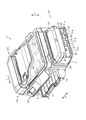
図2に示されるように、筐体30は、複数の液体収容体40が装着される装着部31と、装着部31に装着された状態にある複数の液体収容体40の一部を覆う覆い部32とを含めて構成されている。筐体30には、液体収容体40に収容されたインクの残量を確認するための窓部31wと、液体収容体40に光を入射させる採光部32aとが設けられている。
As shown in FIG. 2, the
図3に示されるように、装着部31は、底壁31aと、底壁31aの端縁から上方に延びて搬送方向Yに交差する一対の側壁31b,31bと、底壁31aの端縁から上方に延びて走査方向Xに交差する内側壁31c及び外側壁31dと、底壁31aの上方に配置される上壁31eとを備える。上壁31eは、その上方がカバー33により覆われ得る。内側壁31cは、走査方向Xに交差する一対の側壁のうちプリンター12Aの本体ケース16側に配置される側壁であり、外側壁31dは、走査方向Xに交差する一対の側壁のうち外側に配置される側壁である。
As shown in FIG. 3, the mounting
上壁31eには、液体収容体40に対応するように上部開口部31xが設けられている。上部開口部31xは、上壁31eにおいて外側壁31d側の端縁から内側壁31cに向かって延びる切欠きとして構成されている。外側壁31dには、上述の窓部31wが液体収容体40の視認面41(図2参照)に対応して設けられている。窓部31wは、外側壁31dにおいて上壁31e側の端縁から底壁31aに向かって延びる切欠きとして構成され、液体収容体40の視認面41(後述参照)を露出させる。
An
覆い部32は、装着部31の上壁31eと液体収容体40との間に配置される(図2参照)。覆い部32は、上壁31eの上部開口部31xの一部分を封鎖する。覆い部32には、上述の採光部32aが設けられている。採光部32aは、液体収容体40の注入口42及びその周囲部(すなわち後述の第2透明部40d)を露出させる。露出させる部分の面積(注入口42を含む面積)は、例えば、注入口42の開口面積の1.5倍以上の大きさに構成される。露出させる部分の面積が小さいと、その効果が表れにくいからである。具体的には、採光部32aは、覆い部32において外側壁31d側の端縁から内側壁31c側に延びる切欠きとして構成される。装着部31の窓部31wと覆い部32の採光部32aとは連結して1つの開口部を構成する(図5参照)。
The
覆い部32には、キャップ45(後述参照)を載置するための載置部32bが設けられている。載置部32bは、覆い部32において、カバー33を開けることにより露出するところに配置されている(図2参照)。
The
図4に示されるように、液体収容体40は、開口部40bを有する箱形の樹脂製容器40aと、開口部40bを封止するシート部材(図示省略)とを備える。インクは、樹脂製容器40aとシート部材とにより囲まれる液体収容室46に貯留される。
As shown in FIG. 4, the
液体収容体40の上部には、液体収容室46にインクを注入するための注入口42が設けられている。注入口42は、液体収容室46の上部において側面部40s寄り(視認面41寄り)に配置され、液体収容体40の上部から上方に向かって突出する筒部として構成されている。液体収容室46と外部(液体収容室46の外側の空間)とは注入口42を介して連通する。
An
注入口42には、当該注入口42を閉塞するキャップ45が着脱可能に設けられている。キャップ45は、注入口42を上方から覆うようにして装着される。また、液体収容体40の上部には、注入口42とは異なる位置に、大気連通孔49が設けられている。大気連通孔49は、液体収容体40内に設けられた第1空気室50と連通する。第1空気室50は、同じく液体収容体40内に設けられた蛇行経路51の一端と連通し、蛇行経路51の他端は、液体収容体40内に設けられた第2空気室52と連通する。第2空気室52は、液体収容室46と連通する。すなわち、大気連通孔49、第1空気室50、蛇行経路51、及び第2空気室52は、液体収容室46内と液体収容室46外とを連通させる大気連通経路53を構成する。大気連通経路53は、液体収容室46内に収容されたインクが記録部13に供給されることに伴って、液体収容室46内が負圧になることを抑制する。
A
液体収容体40には、インクが流出する流出口44が設けられている。流出口44には供給チューブ60が接続されている(図1参照)。供給チューブ60の一端は液体収容体40に接続され、その他端は記録部13に接続されている。すなわち、液体収容体40に収容されるインクは、筐体30から供給チューブ60によって記録ヘッド15に供給される。なお、供給チューブ60は、液体収容体40に対してそれぞれ1本ずつ接続されているが、図1においては、図の簡略化のために1本だけ図示している。
The
図5に示されるように、液体収容体40の側面部40sには、インクの残量を視認させるための視認面41が設けられている。上述したように、視認面41は、筐体30の窓部31wから露出する。視認面41には、液体収容室46に収容可能なインクの上限量を示す上限目盛48が設けられている。
As shown in FIG. 5, the
液体収容体40において視認面41を有する側面部40sは、液体収容室46内に収容されているインクの残量を視認することができるように、透明もしくは半透明の樹脂部材で構成されている。すなわち、液体収容体40の側面部40sにおいて視認面41を含む部分は、第1透明部40cとして構成されている。
The
また、液体収容体40の上部において注入口42の周囲部は、液体収容室46内に光が入射するように、透明もしくは半透明の樹脂部材で構成されている。すなわち、液体収容体40の上部において注入口42の周囲部は第2透明部40dとして構成されている。
Further, the peripheral portion of the
次に、液体供給ユニット20の作用を説明する。
従来の液体供給ユニット(図示略)においても本実施形態の液体供給ユニット20における窓部31wに相当する窓部が設けられている。従って、その窓部を介して液体収容体40の液面は視認される。しかし、従来の液体供給ユニットでは、液体収容体40にインクを注入するときにおいて液面が視認し難くなることがある。インクの注入により液面が上限目盛48に近づくと、視認面41を通過して液体収容体40に進入する光のうちその液面で反射する光(特に、空気層側で反射する光)の量が少なくなるからである。
Next, the operation of the
Also in a conventional liquid supply unit (not shown), a window portion corresponding to the
これに対し、本実施形態の液体供給ユニット20は、その筐体30に光を採り入れる採光部32aを有する。採光部32aは、液体収容体40の注入口42及びその周囲部が露出するように構成されているため、光は、液体収容体40の注入口42及びその周囲部に照射する。また、液体収容体40の注入口42の周囲部は透明または半透明に構成されているため、光は、液体収容体40内に進入し、液面を照らす。このようなことから液面の視認性が高くなる。
On the other hand, the
また、本実施形態では、注入口42は装着部31の上部において視認面41側に配置されているため、注入口42が視認面41とは反対面側に配置されている構成に比べて、注入口42の周囲部から進入し液面で反射して視認面41から出る光の量が増大する。このため、この構成によれば、液面の視認性が更に高くなる。
Moreover, in this embodiment, since the
本実施形態の液体供給ユニット20及びそれを備えるプリンター12Aによれば、以下のような効果を得ることができる。
(1)液体供給ユニット20においては、筐体30の採光部32aを介して光が液体収容体40内に入射するため、液面で反射する光の量が増大し、液面が外部から視認し易くなる。
According to the
(1) In the
(2)また、液体供給ユニット20においては、液体収容体40の第2透明部40dに開口部として機能する採光部32aを介して光が直接入射するため、液面の視認性が高くなる。
(2) Further, in the
(3)また、液体供給ユニット20においては、液体収容体40の第1透明部40cに開口部として機能する窓部31wを介して光が入射するため液面の視認性が高くなる。
(4)また、液体供給ユニット20においては、筐体30の採光部32aと窓部31wとの間を仕切る部材がないことから、採光部32aと窓部31wとを合わせた部分の面積が大きくなり、液体収容体40に入射する光の量が増大する。このため、液面の視認性が向上する。
(3) Moreover, in the
(4) Moreover, in the
(5)また、液体供給ユニット20においては、液体収容体40の第1透明部40cと第2透明部40dとが近くなり、第2透明部40dを介して入射した光のうち第1透明部40cに達する光の量が増大する。このため、液面の視認性が高くなる。
(5) In the
(6)また、液体供給ユニット20においては、液体収容体40の注入口42がカバー33で隠されるため、液体供給ユニット20の外観が向上する。
(7)そして、プリンター12Aでは、液体供給ユニット20と、用紙Pにインクを用いてが画像を記録する記録部13とを備えるので、液体供給ユニット20における場合と同様の作用効果を享受できる。
(6) Moreover, in the
(7) Since the printer 12 </ b> A includes the
(第2実施形態)
図6を参照して、液体供給ユニット20の他の例を説明する。
第1実施形態では、装着部31の窓部31wと覆い部32の採光部32aとが連結されているが、本実施形態では、装着部31の窓部31wと覆い部32の採光部32aとが連結されず、独立して存在する。すなわち、装着部31の窓部31wは、外側壁31dに設けられた貫通孔として構成されている。覆い部32の採光部32aは貫通孔として構成されている。このような構成によっても、実質的に第1実施形態と同様の効果が得られる。
(Second Embodiment)
Another example of the
In the first embodiment, the
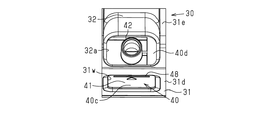
(第3実施形態)
図7を参照して、液体供給ユニット20の他の例を説明する。
第1実施形態では、装着部31の窓部31wと覆い部32の採光部32aとが連結されており、液体収容体40の視認面41(後述参照)が露出し、かつ液体収容体40の注入口42及びその周囲部が露出する。この構成に対して、本実施形態では、装着部31の窓部31wと覆い部32の採光部32aが連結されており、液体収容体40の視認面41と、液体収容体40の注入口42の周囲部とが、透明または半透明な透明部材34により覆われている。透明部材34の表面は凹凸の少ない平坦面(または凹凸がない平坦面)として構成され、液体収容体40の注入口42を挿通する貫通孔34aを有する。透明部材34は、可撓性フィルム、剛性樹脂板、またはガラス板等で構成される。この構成によっても、実質的に第1実施形態と同様の効果が得られる。更に、液体収容体40の視認面41と液体収容体40の注入口42の周囲部とが、透明部材34により覆われるという構成によれば、注入口42から漏れたインクを拭き易いという効果が得られる。視認面41にインクが付着したり、拭った後のインクが固着したりすると、液体収容体40内に入射する光の量が減少し、液面が視認し難くなる。このようなことから、拭き易いという効果は、液面の視認性を高い状態で維持する点、または、液面の視認性を回復させる点においてメリットがある。
(Third embodiment)
With reference to FIG. 7, another example of the
In the first embodiment, the
従って、このような構成によれば、採光部32aは、液体収容体40の第2透明部40dを覆い、表面が平坦な透明部材34により構成されているため、採光部32aに付着したインクが拭い易い。また、窓部31wは、液体収容体40の第1透明部40cを覆い、表面が平坦な透明部材34により構成されているため、窓部31wに付着したインクが拭い易い。
Therefore, according to such a configuration, the
(第4実施形態)
図8を参照して、液体供給ユニット20の他の例を説明する。
本実施形態に係る液体供給ユニット20は、第3実施形態に係る液体供給ユニット20において、装着部31の窓部31wと覆い部32の採光部32aとを独立させたものである。本実施形態では、第2実施形態と同様の効果に加えて、第3実施形態の効果が得られる。
(Fourth embodiment)
With reference to FIG. 8, another example of the
The
(第5実施形態)
図9を参照して、液体供給ユニット20の他の例を説明する。
本実施形態に係る液体供給ユニット20は、第3実施形態に係る液体供給ユニット20において、透明部材34の構成が変更されたものである。透明部材34は、液体収容体40の視認面41を露出させ、かつ液体収容体40の注入口42の周囲部を覆う。この構成によれば、上記透明部材34の存在することによる効果(第3実施形態の効果)に加えて、次の効果を奏する。すなわち、視認面41が露出するため、第3実施形態に比べて液面が視認し易くなるという効果がある。
(Fifth embodiment)
With reference to FIG. 9, another example of the
The
(第6実施形態)
図10を参照して、液体供給ユニット20の他の例を説明する。
本実施形態に係る液体供給ユニット20は、第5実施形態に係る液体供給ユニット20において、装着部31の窓部31wと覆い部32の採光部32aとを独立させたものである。本実施形態では、第5実施形態と同様の効果が得られる。
(Sixth embodiment)
Another example of the
In the
(その他の実施形態)
各実施態様は上記に示した態様に限られるものではなく、各実施形態は以下に示すように変更され得る。
(Other embodiments)
Each embodiment is not limited to the above-described embodiment, and each embodiment can be modified as described below.
・上記各実施形態では、液体収容体40において側面部40sからなる第1透明部40c及び注入口42の周囲部からなる第2透明部40dが、液体収容体40の透明または半透明の部分として構成されているが、液体収容体40において第1透明部40c及び第2透明部40d以外の部分も透明または半透明に構成され得る。すなわち、液体収容体40の全体が透明部材または半透明部材により構成され得る。なお、液体収容体40の全部が透明または半透明部材により構成される場合、視認面41を有する側面部40s以外の部分かつ注入口42の周囲部以外の部分がシールまたは塗料により遮光されるように構成され得る。
In each of the above embodiments, the first
・上記各実施形態において、カバー33の構成は次のように変更され得る。カバー33において、カバー33が閉じられた状態で液体収容体40の注入口42の上方にあたる部分、または当該部分を含む領域は、透明または半透明の部材により構成され得る。この構成によれば、カバー33が閉じられた状態で液体収容体40内に光が入射する。このため、カバー33が閉じられているときでも液面の視認性が高い。
In the above embodiments, the configuration of the
・上記各実施形態において、筐体30は、複数の液体収容体40が装着される装着部31と、複数の液体収容体40の一部を覆う覆い部32とを含めて構成されているが、筐体30の構成はこれに限定されない。筐体30は、液体収容体40を装着し得る構造を有し、かつ、窓部31wと、採光部32aとを有するものであればよい。例えば、筐体30において、覆い部32は省略され得る。この場合、装着部31の上壁31eに採光部32aが構成される。この構成の場合は、液体収容体40が装着部31の下側または横側から差し込むことができるように、底壁31aまたは内側壁31c等が開閉可能または着脱可能に構成される。
In each of the above embodiments, the
12A…プリンター(記録装置)、13…記録部、20…液体供給ユニット、30…筐体、31d…外側壁、31e…上壁、31x…上部開口部、31w…窓部、32…覆い部、32a…採光部、33…カバー、34…透明部材、40…液体収容体、40c…第1透明部、40d…第2透明部、40s…側面部、41…視認面、42…注入口、46…液体収容室、P…用紙(媒体)。 12A ... Printer (recording device), 13 ... Recording unit, 20 ... Liquid supply unit, 30 ... Housing, 31d ... Outer wall, 31e ... Upper wall, 31x ... Upper opening, 31w ... Window, 32 ... Cover, 32a ... lighting part, 33 ... cover, 34 ... transparent member, 40 ... liquid container, 40c ... first transparent part, 40d ... second transparent part, 40s ... side part, 41 ... viewing surface, 42 ... injection port, 46 ... liquid storage chamber, P ... paper (medium).
Claims (10)
前記液体収容体は、前記液体収容体の側面部に設けられた第1透明部と、前記注入口の周囲部に設けられた第2透明部とを有し、
前記筐体は、前記第1透明部を視認可能とする窓部と、前記第2透明部に光を入射させる採光部とを有することを特徴とする液体供給ユニット。 A liquid storage chamber capable of storing a liquid, a liquid storage body having an injection port capable of injecting the liquid into the liquid storage chamber, and a housing in which the liquid storage body is mounted.
The liquid container has a first transparent portion provided on a side surface portion of the liquid container, and a second transparent portion provided on a peripheral portion of the injection port,
The liquid supply unit, wherein the casing includes a window portion that allows the first transparent portion to be visually recognized, and a daylighting portion that allows light to enter the second transparent portion.
請求項1に記載の液体供給ユニット。 The liquid supply unit according to claim 1, wherein the daylighting unit is an opening that exposes the second transparent portion of the liquid container.
請求項1に記載の液体供給ユニット。 The liquid supply unit according to claim 1, wherein the daylighting unit is configured by a transparent member having a flat surface covering the second transparent portion of the liquid container.
請求項2または請求項3に記載の液体供給ユニット。 The liquid supply unit according to claim 2, wherein the window portion is an opening that exposes the first transparent portion of the liquid container.
請求項2または請求項3に記載の液体供給ユニット。 The liquid supply unit according to claim 2, wherein the window portion is configured by a transparent member having a flat surface that covers the first transparent portion of the liquid container.
請求項1〜請求項5のいずれか一項に記載の液体供給ユニット。 The liquid supply unit according to claim 1, wherein the daylighting unit and the window unit are connected.
請求項1〜請求項6のいずれか一項に記載の液体供給ユニット。 The liquid supply unit according to any one of claims 1 to 6, wherein the injection port is disposed so as to approach the side surface portion in an upper portion of the liquid container in which the injection port is disposed.
請求項1〜請求項7のいずれか一項に記載の液体供給ユニット。 The liquid supply unit according to claim 1, wherein a cover that covers the inlet of the liquid container is attached to the casing.
請求項8に記載の液体供給ユニット。 The liquid supply unit according to claim 8, wherein at least a part of the cover is transparent or translucent.
Priority Applications (2)
| Application Number | Priority Date | Filing Date | Title |
|---|---|---|---|
| JP2015238495A JP2017104993A (en) | 2015-12-07 | 2015-12-07 | Liquid supply unit and recording device |
| CN201611058901.1A CN106985539B (en) | 2015-12-07 | 2016-11-21 | Fluid supply unit and recording device |
Applications Claiming Priority (1)
| Application Number | Priority Date | Filing Date | Title |
|---|---|---|---|
| JP2015238495A JP2017104993A (en) | 2015-12-07 | 2015-12-07 | Liquid supply unit and recording device |
Publications (1)
| Publication Number | Publication Date |
|---|---|
| JP2017104993A true JP2017104993A (en) | 2017-06-15 |
Family
ID=59058407
Family Applications (1)
| Application Number | Title | Priority Date | Filing Date |
|---|---|---|---|
| JP2015238495A Pending JP2017104993A (en) | 2015-12-07 | 2015-12-07 | Liquid supply unit and recording device |
Country Status (2)
| Country | Link |
|---|---|
| JP (1) | JP2017104993A (en) |
| CN (1) | CN106985539B (en) |
Cited By (1)
| Publication number | Priority date | Publication date | Assignee | Title |
|---|---|---|---|---|
| JP2021006378A (en) * | 2019-06-28 | 2021-01-21 | セイコーエプソン株式会社 | Liquid discharge device |
Family Cites Families (5)
| Publication number | Priority date | Publication date | Assignee | Title |
|---|---|---|---|---|
| JP3273715B2 (en) * | 1995-08-09 | 2002-04-15 | ブラザー工業株式会社 | Color inkjet printer |
| JP2004009488A (en) * | 2002-06-06 | 2004-01-15 | Canon Inc | Residual ink quantity detecting apparatus |
| CN2562973Y (en) * | 2002-07-18 | 2003-07-30 | 洪肇荣 | Ink box for printer |
| KR200315829Y1 (en) * | 2003-03-05 | 2003-06-12 | 김규남 | Ink refill equipment for waste ink cartridge |
| RU2018105185A (en) * | 2012-08-10 | 2019-02-25 | Сейко Эпсон Корпорейшн | LIQUID CONTAINER, LIQUID CONSUMPTION DEVICE, LIQUID FEEDING SYSTEM AND LIQUID CONTAINER UNIT |
-
2015
- 2015-12-07 JP JP2015238495A patent/JP2017104993A/en active Pending
-
2016
- 2016-11-21 CN CN201611058901.1A patent/CN106985539B/en active Active
Cited By (2)
| Publication number | Priority date | Publication date | Assignee | Title |
|---|---|---|---|---|
| JP2021006378A (en) * | 2019-06-28 | 2021-01-21 | セイコーエプソン株式会社 | Liquid discharge device |
| JP7342454B2 (en) | 2019-06-28 | 2023-09-12 | セイコーエプソン株式会社 | liquid discharge device |
Also Published As
| Publication number | Publication date |
|---|---|
| CN106985539A (en) | 2017-07-28 |
| CN106985539B (en) | 2018-08-03 |
Similar Documents
| Publication | Publication Date | Title |
|---|---|---|
| US10286676B2 (en) | Recording apparatus | |
| JP6794783B2 (en) | Liquid injection device | |
| JP6852394B2 (en) | Liquid injection device | |
| JP6503685B2 (en) | Liquid supply device | |
| US10245865B2 (en) | Recording apparatus | |
| JP2018103593A (en) | Printing fluid cartridge, printing fluid cartridge set, and system | |
| JP6657670B2 (en) | Recording device | |
| JP6780237B2 (en) | Liquid containment | |
| JP6365318B2 (en) | Liquid consumption device | |
| JP2019142116A (en) | Liquid storage container and recording device | |
| TW201800268A (en) | Recording device solves the problem of residual printer ink amount adversely affected by dust or damage from the outside of the printer | |
| JP2017104993A (en) | Liquid supply unit and recording device | |
| JP2016132164A (en) | Liquid consuming device | |
| US10525751B2 (en) | Liquid ejecting apparatus | |
| JP6358106B2 (en) | Liquid consumption device | |
| JP2010012602A (en) | Package and ink cartridge | |
| JP2008188809A (en) | Ink cartridge and cartridge holding apparatus | |
| JP2019005963A (en) | Recording device | |
| JP2018171874A (en) | Liquid consuming device | |
| CN107031193B (en) | Liquid container and liquid ejecting apparatus | |
| JP6347202B2 (en) | Liquid consumption device | |
| JP6278075B2 (en) | Liquid container and liquid consumption apparatus | |
| JP6711018B2 (en) | Liquid supply device | |
| JP7342454B2 (en) | liquid discharge device | |
| JP7052485B2 (en) | Liquid consuming equipment and management system |