JP6278075B2 - Liquid container and liquid consumption apparatus - Google Patents
Liquid container and liquid consumption apparatus Download PDFInfo
- Publication number
- JP6278075B2 JP6278075B2 JP2016149417A JP2016149417A JP6278075B2 JP 6278075 B2 JP6278075 B2 JP 6278075B2 JP 2016149417 A JP2016149417 A JP 2016149417A JP 2016149417 A JP2016149417 A JP 2016149417A JP 6278075 B2 JP6278075 B2 JP 6278075B2
- Authority
- JP
- Japan
- Prior art keywords
- liquid
- ink
- storage chamber
- unit
- illumination unit
- Prior art date
- Legal status (The legal status is an assumption and is not a legal conclusion. Google has not performed a legal analysis and makes no representation as to the accuracy of the status listed.)
- Active
Links
Images


Description
本発明は、例えばインクジェット式のプリンターなどの液体消費装置、該液体消費装置で消費される液体を収容する液体収容体、及び該液体収容体を備える液体収容体ユニットに関する。 The present invention relates to a liquid consuming device such as an ink jet printer, a liquid container that contains a liquid consumed by the liquid consuming device, and a liquid container unit including the liquid container.
従来から、インク(液体)を噴射する噴射ヘッド(液体消費部)で消費されるインクを収容可能なインクタンク(液体収容体)を備えたインクジェット式のプリンターが知られている(例えば特許文献1)。 2. Description of the Related Art Conventionally, an ink jet printer including an ink tank (liquid container) that can store ink consumed by an ejection head (liquid consumption unit) that ejects ink (liquid) is known (for example, Patent Document 1). ).
そして、こうしたプリンターに備えられるインクタンクには、通常、インクタンク内に収容されたインクの液面の位置を目視可能な確認窓(視認面)が設けられている。 An ink tank provided in such a printer is usually provided with a confirmation window (viewing surface) through which the position of the liquid level of the ink stored in the ink tank can be visually observed.
ところで、例えばインクタンク内の壁面がインクで濡れていたり、インクタンク内に濃い色のインクが収容されていたりすると、インクの液面の位置を目視しにくかった。特に、インクを注入可能なインクタンクの場合には、インクの注入時にインクの液面の位置を視認できずに収容量以上のインクを注入すると、インクが溢れて周囲を汚してしまう虞がある。 By the way, for example, if the wall surface in the ink tank is wet with ink, or if dark ink is contained in the ink tank, it is difficult to see the position of the ink surface. In particular, in the case of an ink tank capable of injecting ink, when the ink level is not visually recognized at the time of ink injection and more ink is contained, there is a risk that the ink will overflow and stain the surroundings. .
なお、こうした問題はインクジェット式のプリンターに備えられるインクタンクに限らず、液体を収容する液体収容体においては概ね共通するものとなっていた。
本発明は、こうした実情に鑑みてなされたものであり、その目的は、液体注入時において液体収容体に収容された液体の液面の位置を容易に視認することができる液体収容体、液体収容体ユニット、及び液体収容体を備える液体消費装置を提供することにある。
Such problems are not limited to ink tanks provided in ink jet printers, but are generally common in liquid containers that contain liquid.
The present invention has been made in view of such circumstances, and an object of the present invention is to provide a liquid container that can easily recognize the position of the liquid level of the liquid contained in the liquid container when the liquid is injected. An object of the present invention is to provide a liquid consuming device including a body unit and a liquid container.
以下、上記課題を解決するための手段及びその作用効果について記載する。
上記課題を解決する液体収容体は、液体を収容する液体収容室と、前記液体収容室内に外部から前記液体を注入可能とする開口部を有する液体注入口と、前記液体収容室を照明可能な照明部と、を備える。
上記課題を解決する液体収容体は、液体を消費する液体消費部に供給する前記液体を収容する液体収容室と、該液体収容室内から前記液体を前記液体消費部側に導出可能とする液体導出口と、前記液体収容室内に外部から前記液体を注入可能とする液体注入口と、前記液体収容室に収容された前記液体の液面を鉛直方向と交差する方向から視認可能な視認面と、前記液体収容室を照らす照明部と、前記液体注入口から前記液体を注入する液体注入時と前記液体を注入しない液体非注入時とで位置を変位させる変位部材とを備え、前記照明部は、前記変位部材が前記液体非注入時に位置する液体非注入時位置から変位するのに伴って点灯する。
Hereinafter, means for solving the above-described problems and the effects thereof will be described.
A liquid container that solves the above-described problem is capable of illuminating the liquid storage chamber, a liquid inlet having an opening that allows the liquid to be injected into the liquid storage chamber from the outside, and the liquid storage chamber. An illumination unit.
A liquid container that solves the above problems includes a liquid storage chamber that stores the liquid to be supplied to a liquid consumption unit that consumes liquid, and a liquid guide that allows the liquid to be led out from the liquid storage chamber to the liquid consumption unit. An outlet, a liquid injection port capable of injecting the liquid from the outside into the liquid storage chamber, and a viewing surface that is visible from the direction intersecting the vertical direction with the liquid level of the liquid stored in the liquid storage chamber; An illumination unit that illuminates the liquid storage chamber; and a displacement member that displaces a position when liquid is injected from the liquid injection port and when liquid is not injected without liquid injection. Lights when the displacement member is displaced from the non-liquid injection position, which is located when the liquid is not injected.
この構成によれば、液体注入口から液体収容室内へ液体を注入する際には、変位部材が液体非注入時位置から変位させられるとともに、そのように変位部材が液体非注入時位置から変位したことに伴って照明部が点灯するため、その照明部によって液体収容室が照らされる。したがって、液体注入時において液体収容体に収容された液体の液面の位置を容易に視認することができる。 According to this configuration, when the liquid is injected from the liquid inlet into the liquid storage chamber, the displacement member is displaced from the liquid non-injection position and the displacement member is displaced from the liquid non-injection position. Accordingly, since the illumination unit is turned on, the liquid storage chamber is illuminated by the illumination unit. Therefore, the position of the liquid surface of the liquid stored in the liquid container can be easily visually confirmed at the time of liquid injection.
上記液体収容体において、前記照明部は、前記液体収容室を挟んで前記視認面とは反対側から前記視認面側に向けて前記液体収容室を照らすのが好ましい。
この構成によれば、照明部は、視認面側から見て奧側となる位置から視認面側に向けて液体収容室を照らすことになるため、他の位置から液体収容室を照らす場合に比べて視認面に到達する光量を増やすことができる。したがって、液体収容室に収容された液体の液面の位置を、より一層、視認しやすくすることができる。
In the liquid container, it is preferable that the illumination unit illuminates the liquid storage chamber from the side opposite to the viewing surface to the viewing surface side across the liquid storage chamber.
According to this configuration, the illumination unit illuminates the liquid storage chamber from the position on the heel side when viewed from the viewing surface side toward the viewing surface side, so compared to the case where the liquid storage chamber is illuminated from another position. The amount of light reaching the viewing surface can be increased. Therefore, the position of the liquid level of the liquid stored in the liquid storage chamber can be further easily recognized.
また、上記課題を解決する液体収容体ユニットは、液体を消費する液体消費部に供給する前記液体を収容する液体収容室と、該液体収容室内から前記液体を前記液体消費部側に導出可能とする液体導出口と、前記液体収容室内に外部から前記液体を注入可能とする液体注入口と、前記液体収容室に収容された前記液体の液面を鉛直方向と交差する方向から視認可能な視認面とを備える液体収容体を少なくとも2つ備えると共に、前記各液体収容室を照らす照明部と、前記液体注入口から前記液体を注入する液体注入時と前記液体を注入しない液体非注入時とで位置を変位させる変位部材とをさらに備え、前記照明部は、前記変位部材が前記液体非注入時に位置する液体非注入時位置から変位するのに伴って点灯する。 In addition, a liquid container unit that solves the above-described problem includes a liquid storage chamber that stores the liquid supplied to the liquid consumption unit that consumes the liquid, and the liquid can be led out from the liquid storage chamber to the liquid consumption unit side. And a liquid inlet that allows the liquid to be injected from the outside into the liquid storage chamber, and a visual recognition that allows the liquid level of the liquid stored in the liquid storage chamber to be viewed from a direction that intersects the vertical direction. At least two liquid containers each having a surface, and an illuminating unit that illuminates each liquid storage chamber, and when liquid is injected from the liquid inlet and when liquid is not injected without liquid. A displacement member for displacing the position, and the illumination unit is lit when the displacement member is displaced from a non-liquid-injecting position located when the liquid is not infused.
この構成によれば、変位部材が液体非注入時位置から変位するのに伴って照明部が点灯するため、液体収容室へ液体を注入する際には照明部によって各液体収容室が照らされる。そのため、少なくとも2つの液体収容体への液体注入時において各液体収容体に収容された液体の液面の位置を液体収容体ごとに容易に視認することができる。 According to this configuration, since the illumination unit is lit as the displacement member is displaced from the liquid non-injection position, each liquid storage chamber is illuminated by the illumination unit when the liquid is injected into the liquid storage chamber. Therefore, the position of the liquid level of the liquid stored in each liquid container can be easily visually recognized for each liquid container when liquid is injected into at least two liquid containers.
上記液体収容体ユニットにおいて、前記照明部と前記変位部材は、少なくとも2つの前記液体収容体に個別に対応して設けられ、少なくとも2つの前記照明部は、少なくとも2つの前記変位部材のうち前記液体非注入時位置から変位する変位部材と対応する前記液体収容体を照らす照明部が点灯するのが好ましい。 In the liquid container unit, the illumination unit and the displacement member are individually provided corresponding to at least two of the liquid containers, and at least two of the illumination units include the liquid of at least two of the displacement members. It is preferable that the illumination unit that illuminates the liquid container corresponding to the displacement member displaced from the non-injection position is lit.
この構成によれば、少なくとも2つの液体収容体のうち変位部材が液体非注入時位置から変位した液体収容体と対応する照明部が点灯する。そのため、照明部が選択的に点灯することで省エネ性を確保しつつ、液体が注入される液体収容体に収容された液体の液面の位置を容易に視認することができる。 According to this structure, the illumination part corresponding to the liquid container which the displacement member displaced from the position at the time of liquid non-injection among at least two liquid containers is turned on. Therefore, the position of the liquid surface of the liquid accommodated in the liquid container into which the liquid is injected can be easily visually recognized while ensuring energy saving by selectively lighting the illumination unit.
上記課題を解決する液体消費装置は、液体を消費する液体消費部と、前記液体を収容する液体収容室と、前記液体収容室内から前記液体を前記液体消費部側に導出可能とする液体導出口と、前記液体収容室内に外部から前記液体を注入可能とする液体注入口と、前記液体収容室を照明可能な照明部と、を備える。
さらに、上記課題を解決する液体消費装置は、液体を消費する液体消費部と、該液体消費部に供給する前記液体を収容する液体収容室と、該液体収容室内から前記液体を前記液体消費部側に導出可能とする液体導出口と、前記液体収容室内に外部から前記液体を注入可能とする液体注入口と、前記液体収容室に収容された前記液体の液面を鉛直方向と交差する方向から視認可能な視認面と、前記液体収容室を照らす照明部と、前記液体注入口から前記液体を注入する液体注入時と前記液体を注入しない液体非注入時とで位置を変位させる変位部材とを備え、前記照明部は、前記変位部材が前記液体非注入時に位置する液体非注入時位置から変位するのに伴って点灯する。
A liquid consuming device that solves the above problems includes a liquid consuming unit that consumes liquid, a liquid containing chamber that contains the liquid, and a liquid outlet that allows the liquid to be led out from the liquid containing chamber to the liquid consuming unit side. And a liquid inlet that allows the liquid to be injected into the liquid storage chamber from the outside, and an illumination unit that can illuminate the liquid storage chamber.
Furthermore, a liquid consuming device that solves the above problems includes a liquid consuming unit that consumes liquid, a liquid containing chamber that contains the liquid supplied to the liquid consuming unit, and the liquid consuming unit that receives the liquid from the liquid containing chamber. A liquid outlet port that can be led out to the side, a liquid inlet port that can inject the liquid from the outside into the liquid storage chamber, and a direction that intersects the liquid surface of the liquid stored in the liquid storage chamber with the vertical direction A viewing surface that is visible from the lighting unit, an illuminating unit that illuminates the liquid storage chamber, and a displacement member that displaces a position when liquid is injected from the liquid injection port and when liquid is not injected without liquid injection. The illumination unit is lit when the displacement member is displaced from the liquid non-injection position, which is located when the liquid is not injected.
この構成によれば、上記液体収容体に係る発明と同様の作用効果を奏し得る。 According to this configuration, the same operational effects as those of the invention relating to the liquid container can be obtained.
(第1実施形態)
以下、液体消費装置の一例である記録装置の第1実施形態について、図を参照して説明する。
(First embodiment)
Hereinafter, a first embodiment of a recording apparatus which is an example of a liquid consuming apparatus will be described with reference to the drawings.
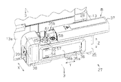
図1に示すように、複合機11は、記録装置12と、記録装置12の装置本体13上に搭載されたスキャナーユニット14とを備えている。
記録装置12は、用紙Pに対して記録を行うことが可能である一方、スキャナーユニット14は原稿に記録された画像等を読みとることが可能である。なお、本明細書では、反重力方向を上方向というとともに、重力方向を下方向という。また、これら上方向及び下方向に沿う方向を鉛直方向の一例としての上下方向Zとして図示する。
As shown in FIG. 1, the multifunction machine 11 includes a recording device 12 and a
The recording device 12 can record on the paper P, while the
スキャナーユニット14は、記録装置12の装置本体13に対して一部が回動自在に連結されたスキャナー本体部15と、スキャナー本体部15の上方に配置された搬送ユニット16とを備えている。スキャナー本体部15は、その一端側に設けられたヒンジなどの回転機構17を介して、記録装置12に対して装置本体13の上方を覆う閉位置と装置本体13の上方を開放する開位置との間での変位可能に取り付けられている。また、搬送ユニット16は、その一端側に設けられたヒンジなどの回転機構18を介して、スキャナー本体部15に対してスキャナー本体部15の上方を覆う位置と開放する位置との間での変位可能に取り付けられている。
The
なお、以下の説明においては、複合機11において、回転機構17,18が設けられた側を後側または背面側というとともに、その反対側を前側という。また、前方向及び後方向に沿う方向を前後方向Yとして図示する。そして、スキャナーユニット14、スキャナー本体部15及び搬送ユニット16は、その前端側が上方に向けて回動可能となっている。
In the following description, in the multifunction machine 11, the side on which the
さらに、前側から後方向を見た場合(正面視)の右方向及び左方向に沿う方向を左右方向Xとして図示する。なお、左右方向X、前後方向Y、上下方向Zは、互いに交差(本実施形態では直交)する。したがって、本実施形態における左右方向X及び前後方向Yは、水平方向に沿う方向である。 Furthermore, the direction along the right direction and the left direction when the rear direction is viewed from the front side (front view) is illustrated as the left-right direction X. Note that the left-right direction X, the front-rear direction Y, and the up-down direction Z intersect with each other (in the present embodiment, orthogonal). Therefore, the left-right direction X and the front-back direction Y in the present embodiment are directions along the horizontal direction.
複合機11の前面側には操作パネル19が配置されている。操作パネル19はメニュー画面等を表示するための表示部(例えば液晶ディスプレイ)20と、表示部20の周囲に設けられた種々の操作ボタン21とを備えている。
An
記録装置12において操作パネル19の下方にあたる位置は、装置本体13内から用紙Pを排出するための排出口22が開口している。また、記録装置12における排出口22の下方には、引き出し可能な排紙台23が収容されている。
At the position below the
記録装置12の背面側には、複数の用紙Pを積載可能な略矩形板状をなす引き出し式の媒体支持体24が取り付けられている。また、スキャナー本体部15の後部には、基端側(本実施形態では前端側)を中心に回動可能な導入口カバー25が取り付けられている。
On the back side of the recording apparatus 12, a drawer-
また、装置本体13の外部であって右側面となる取付面13aには、インク(液体の一例)を収容するタンクユニット27が固着されている。また、装置本体13とタンクユニット27の間となる位置であって、且つ取付面13aの後寄りの位置には、スケール28aを収容するスケール収容部28が設けられている。スケール収容部28は、スケール28aの厚さに対応した左右方向Xの深さ及びスケール28aの幅に対応した前後方向Yの幅で上下方向Zに長い矩形の溝形状をなすように、取付面13aに凹み形成されている。
Further, a
一方、装置本体13の内部には、主走査方向となる左右方向Xに往復移動可能な状態で保持されたキャリッジ29と、キャリッジ29に装着された中継アダプター30とが設けられている。中継アダプター30には、一端側がタンクユニット27に接続された可撓性を有するチューブ31の他端側が接続されている。また、キャリッジ29の下面側には、タンクユニット27から供給されたインクを噴射可能な液体消費部の一例としての液体噴射ヘッド32が支持されている。
On the other hand, inside the apparatus
したがって、タンクユニット27に収容されたインクは、水頭差を利用することによりチューブ31を介して液体噴射ヘッド32へ供給される。そして、液体噴射ヘッド32に供給されたインクが搬送機構(図示略)によって搬送される用紙Pに対して噴射されることで記録(液体の消費の一例)が行われる。
Accordingly, the ink stored in the
以下、図2に示すタンクユニット27について説明する。
なお、タンクユニット27における左右方向X、前後方向Y、上下方向Zは、タンクユニット27が装置本体13に取り付けられた状態での各方向を基準とする。
Hereinafter, the
The left-right direction X, the front-rear direction Y, and the up-down direction Z in the
さて、図2に示すように、タンクユニット27は、タンクケース35と、該タンクケース35内に収容される液体収容体の一例としてのインクタンク36とを備えている。タンクケース35における前後方向Y及び上下方向Zに沿う外面(この場合、右側面)を形成する壁部には、タンクケース35の内外を連通する略矩形状の窓部35aが形成されている。したがって、インクタンク36は、タンクケース35内に収容された状態において、その一部が窓部35aを介してタンクケース35の外部から視認可能である。
As shown in FIG. 2, the
さらに、タンクユニット27は、タンクケース35に対して前後方向Yにスライド移動する変位部材の一例としてのカバー37と、タンクケース35内に収容されるチョークバルブ38とを備えている。タンクケース35の前面には、チョークバルブ38を操作するためのバルブレバー39が設けられている。なお、チョークバルブ38は、ユーザーによってバルブレバー39が操作されるのに伴ってチューブ31を押し潰し、インクタンク36から液体噴射ヘッド32へのインクの供給を遮断する。
Furthermore, the
次に、インクタンク36について説明する。
図3に示すように、インクタンク36は、タンク開口部36aにフィルム41が貼着されることにより、インクを収容する液体収容室の一例としてのインク室42が形成されている。
Next, the
As shown in FIG. 3, the
さらに、インクタンク36は、透明もしくは半透明の樹脂製であって、インクタンク36の外側からインク室42内に収容されたインク及びインクの液面43が視認可能である。そのため、インクタンク36がタンクケース35に装着されると、タンクケース35の窓部35aを介して外部からインク室42に収容されたインクが視認可能となる。すなわち、インクタンク36の右側面において窓部35aと対応する領域は、右方向からインク室42に収容されたインクの液面43を視認可能な視認面36bとして機能している。
Further, the
また、インクタンク36の上部には、インク室42内に外部からインクを注入可能とする液体注入口の一例としての注入口44が形成されている。注入口44は、インク室42の外側に向かって突出すると共に、上下方向Zに対して非直交、且つ水平方向よりも上方向となる右上方向に向かって突出する筒部45の先端に開口するように形成されている。
In addition, an
図2,図3に示すように、筒部45の先端には、注入口44を閉塞可能な閉塞部材47が着脱可能に取り付けられている。なお、閉塞部材47には、一端がタンクケース35に接続された繋留部48の他端側が接続されている。さらに、閉塞部材47には、上側に摘み部49が形成されていると共に、下側に注入口44と嵌合する円管状の嵌合部50が形成されている。
As shown in FIGS. 2 and 3, a closing
また、図4に示すように、インクタンク36の前面の下方位置には、チューブ31(図4では図示略)が接続されると共に、インク室42内からインクを液体噴射ヘッド32側へ導出可能とする液体導出口の一例としての導出口52が形成されている。さらに、インクタンク36の上部には、インク室42内に空気を取り入れる空気取入口53が形成されている。
As shown in FIG. 4, a tube 31 (not shown in FIG. 4) is connected to the lower position of the front surface of the
図2に示すように、視認面36bにおける前側位置には、下限目盛54と上限目盛55とが上下方向Zに間隔を有して突出形成されている。なお、下限目盛54は、インク室42へインクを注入する目安となる下限量を示す目盛である。また、上限目盛55は、注入口44から注入されてインク室42内に収容されるインクの上限量を示す目盛である。
As shown in FIG. 2, a
次に、タンクケース35について説明する。
図2,図3に示すようにタンクケース35の上面における前側位置には、上下方向Zの高さが上面よりも一段低くなった谷部35bが形成されている。谷部35bには、インクタンク36がタンクケース35に装着される際にケース開口部35c側となる左側から谷部35b内への筒部45の進入を受容する上面視U字状の受容部57が形成されている。さらに、谷部35b内において、受容部57の後方は、受容部57が形成された位置よりも1段高く形成されていると共に、閉塞部材47を載置可能な載置部58が形成されている。
Next, the
As shown in FIGS. 2 and 3, a
図3,図4に示すように、インクタンク36の側面においてインク室42を挟んで視認面36bとは反対側の側面、すなわち、タンク開口部36aに貼着されたフィルム41の表面により形成される側面には、照明部59が設けられている。この照明部59は、例えば多数のLED(発光ダイオード)を面状に散りばめた面状発光体などからなり、図3に示す形態では、その左右方向Xでの右側面部分が発光部分となっている。そして、本実施形態の場合、その照明部59は、インクタンク36を視認面36b側から見て奥側となる位置から視認面36b側に向けてインク室42を照らすように設けられている。
As shown in FIGS. 3 and 4, the
なお、図4に示すように、照明部59は、インク室42の前後方向Yにおける途中位置よりも下限目盛54と上限目盛55、及び注入口44が形成された側となる前側位置に設けられている。さらに、照明部59は、その発光部分(図3における右側面部分)の全体が下限目盛54よりも上側に位置し、且つ、その発光部分の上側略半分が上限目盛55よりも上側に位置するように設けられている。すなわち、照明部59は、その発光部分が発光した場合に、インク室42に収容されたインクの液面43よりも上方位置からインク室42内を照らすように配置されている。ちなみに、照明部59は、その発光部分の少なくとも一部が上限目盛55よりも上側に位置していることが好ましく、その発光部分の全体が上限目盛55よりも上側に位置していてもよい。
As shown in FIG. 4, the
次に、インク室にインクを注入する作用について説明する。
まず、図1に示すように、カバー37は、注入口44が形成された筒部45と載置部58とを隠蔽する隠蔽位置Aに位置しているものとする。すなわち、カバー37は、インク室42に収容されたインクが液体噴射ヘッド32から噴射される記録時や、注入口44からインクの注入がなされない非注入時には隠蔽位置Aに位置する。したがって、本実施形態では、この隠蔽位置Aが、液体非注入時に変位部材が位置する液体非注入時位置に相当する。
Next, the operation of injecting ink into the ink chamber will be described.
First, as shown in FIG. 1, the
さて、図2に示すように、インク室42にインクを注入する場合には、ユーザーは、隠蔽位置Aに位置するカバー37を後方へスライド移動させて非隠蔽位置Bに位置させる。すると、カバー37によって隠蔽されていた筒部45と載置部58とが出現する。さらに、ユーザーが筒部45に取り付けられた閉塞部材47を載置部58に変位させると、注入口44が出現する。すなわち、非隠蔽位置Bは、注入口44からインクを注入するインク注入時(液体注入時の一例)にカバー37が位置する位置であり、本実施形態では、この非隠蔽位置Bが、液体注入時に変位部材が位置する液体注入時位置に相当する。
As shown in FIG. 2, when injecting ink into the
また、カバー37が隠蔽位置(液体非注入時位置)Aから非隠蔽位置(液体注入時位置)Bに変位すると、図示しないスイッチがONされて照明部59が点灯する。そのため、ユーザーは照明部59によって照らされた液面43の位置を視認しつつ注入口44からインクを注入することが可能となる。
When the
インクを注入し終わると、ユーザーは載置部58に載置した閉塞部材47を筒部45に戻し、非隠蔽位置Bに位置するカバー37を前方へスライド移動させて隠蔽位置Aまで変位させる。すると、照明部59は、図示しないスイッチがOFFされて消灯する。
When the ink has been injected, the user returns the closing
上記第1実施形態によれば、以下のような効果を得ることができる。
(1)注入口44からインク室42内へインクを注入する際には、カバー37が隠蔽位置Aから変位させられるとともに、そのようにカバー37が隠蔽位置Aから変位したことに伴って照明部59が点灯する。そのため、インク室42へインクを注入する際には照明部59によってインク室42が照らされる。したがって、インク注入時においてインクタンク36に収容されたインクの液面43の位置を容易に視認することができる。
According to the first embodiment, the following effects can be obtained.
(1) When ink is injected from the
(2)照明部59は、視認面36b側から見て奧側となる位置から視認面36b側に向けてインク室42を照らすことになるため、他の位置からインク室42を照らす場合に比べて視認面36bに到達する光量を増やすことができる。したがって、インク室42に収容されたインクの液面43の位置を、より一層、視認しやすくすることができる。
(2) Since the
(3)照明部59は、視認面36bにおける前後方向Yの途中位置よりも注入口44が形成された前側に形成されているため、より一層、注入されるインクを視認しやすくすることができる。
(3) Since the
(4)照明部59は、視認面36bにおける前後方向Yの途中位置よりも下限目盛54と上限目盛55が形成された前側に形成されているため、より一層、下限目盛54及び上限目盛55と注入されるインクの液面43とを視認しやすくすることができる。すなわち、下限目盛54と液面43とが比較しやすくなるため、インクの注入の必要性を的確にユーザーに伝えることができる。また、上限目盛55と液面43とが比較しやすくなるため、インクがインク室42に必要以上に注入されて注入口44から溢れてしまう虞を低減することができる。
(4) Since the
(5)照明部59(より具体的には発光部分)の少なくとも一部を上限目盛55よりも上側に設けることにより、インク室42に収容されたインクの液面43よりも上側からインク室42内を照らすことができる。したがって、インクの液面43よりも下側からインク室42内を照らす場合に比べてユーザーに液面43を視認させやすくすることができる。
(5) By providing at least a part of the illumination unit 59 (more specifically, the light emitting part) above the
(第2実施形態)
次に、液体消費装置の一例であるインクジェット式プリンター(以下、「プリンター」ともいう。)の第2実施形態について、図面を参照しながら説明する。なお、この第2実施形態は、第1実施形態と同一の構成については同一符号を付すことによって重複した説明を省略する。
(Second Embodiment)
Next, a second embodiment of an ink jet printer (hereinafter also referred to as “printer”), which is an example of a liquid consuming apparatus, will be described with reference to the drawings. In the second embodiment, the same components as those in the first embodiment are denoted by the same reference numerals, and redundant description is omitted.
図5に示すように、本実施形態のプリンター61は、車輪62が下端に取り付けられた脚部63と、脚部63上に組み付けられる略直方体状の装置本体64とを備えている。装置本体64の後部には、上方に向けて突出する給送部65が設けられている。給送部65内には、長尺の媒体としての用紙Sが円筒状に巻き重ねられたロール紙Rが装填されている。装置本体64の外装を構成する筐体部66において、給送部65の前側となる位置には給送部65から送り出される用紙Sを筐体部66内へ導入するための挿入口67が形成されている。
As shown in FIG. 5, the
一方、装置本体64の前面側には、用紙Sを筐体部66外に排出するための排出口68が形成されている。なお、筐体部66内には、給送部65から給送された用紙Sを挿入口67側から排出口68側に向けて搬送する図示しない媒体搬送機構が収容されている。そして、装置本体64の前面側において排出口68よりも下方となる位置には、排出口68から排出された用紙Sを受ける媒体受けユニット69が設けられている。
On the other hand, a discharge port 68 for discharging the paper S to the outside of the
また、装置本体64の上部において、左右方向Xで用紙Sの搬送経路の外側となる一端側(図1では右端側)には、設定操作や入力操作を行うための操作パネル70が設けられている。さらに、装置本体64の下部において、左右方向Xで用紙Sの搬送経路の外側となる一端側(図1では右端側)には、インクを収容可能な液体収容体の一例としてのインクタンク71〜74が固定されている。
In addition, an
インクタンク71〜74は、インクの種類や色に対応して、少なくとも2つ(本実施形態では4つ)設けられている。そして、インクタンク71〜74が左右方向Xに並ぶように配置されることで液体収容体ユニットの一例としての収容体ユニット75を構成している。
At least two (four in this embodiment)
なお、各インクタンク71〜74の構成は同じであるため、以下では第1インクタンク71の構成を説明することにより、第2インクタンク72〜第4インクタンク74の説明を省略する。
In addition, since the structure of each ink tank 71-74 is the same, description of the 2nd ink tank 72-the
図6に示すように、インクタンク71は、少なくとも前側の面が透明もしくは半透明の樹脂製であって、インクタンク71の前側からインク室77内に収容されたインク及びインクの液面(図示略)が視認可能である。すなわち、インクタンク71が装置本体64に装着されると、インクタンク71〜74の前側の面がインク室77に収容されたインクの液面(図示略)を前方向から視認可能な視認面78として機能する。
As shown in FIG. 6, the
インクタンク71には、インク室77内に収容されたインクの残量を検出する残量検出部79が設けられている。そして、インク室77に収容されたインクは、液体導出口の一例としての導出口80から液体噴射ヘッド32側へ導出される際に、残量検出部79を通過する。
The
また、インクタンク71の上部には、インク室42内に外部からインクを注入可能とする液体注入口の一例としての注入口81が形成されている。さらに、インクタンク71の上部には、注入口81を閉塞可能な閉塞部材82と、軸83を中心に回動する変位部材の一例としてのカバー84とが設けられている。
In addition, an
すなわち、カバー84は、図6に示す第2インクタンク72〜第4インクタンク74のカバー84が位置する隠蔽位置Aと、図6に示す第1インクタンク71のカバー84が位置する非隠蔽位置Bとの間を回動変位する。そして、隠蔽位置Aに位置するカバー84は、注入口81及び注入口81を閉塞する閉塞部材82を隠蔽する。なお、カバー84は、記録時や、非注入時には隠蔽位置Aに位置する。
That is, the
一方、インク注入時には、カバー84が非隠蔽位置Bに位置する。そして、非隠蔽位置Bに位置したカバー84の裏側は、閉塞部材82を載置可能な載置部85となる。
また、インクタンク71の上下方向Zにおけるサイズは、前側に比べて後側が小さい。そして、上下方向Zにおけるサイズが大きい前側の部分において後側の面には、照明部86が設けられている。すなわち、照明部86は、インクタンク71のインク室77を挟んで視認面78とは反対側の面であって、視認面78側から見て奥側に設けられている。
On the other hand, the
Further, the size of the
次に、第1インクタンク71のインク室77にインクを注入する作用について説明する。
なお、カバー37は、隠蔽位置Aに位置しているものとする。さて、インク室42にインクを注入する場合には、ユーザーは、隠蔽位置Aに位置するカバー84を後方へ回動させて非隠蔽位置Bまで回動変位させる。すると、カバー84によって隠蔽されていた閉塞部材82と載置部85とが出現する。さらに、ユーザーが閉塞部材82を載置部85に変位させると、注入口81が出現する。
Next, the operation of injecting ink into the
It is assumed that the
また、カバー84が隠蔽位置Aから非隠蔽位置Bに変位すると、図示しないスイッチがONされて非隠蔽位置Bに変位したカバー84と対応する第1インクタンク71の照明部86が点灯する。一方、カバー84が隠蔽位置Aに位置する第2インクタンク72〜第4インクタンク74の照明部86は消灯した状態を維持する。そして、ユーザーは照明部86によって照らされた液面(図示略)の位置を視認しつつ第1インクタンク71の注入口81からインクを注入する。
When the
インクを注入し終わると、ユーザーは載置部85に載置した閉塞部材82を注入口81に戻し、非隠蔽位置Bに位置するカバー84を前方へ回動させて隠蔽位置Aまで変位させる。すると、第1インクタンク71の照明部86は、図示しないスイッチがOFFされて消灯する。
When the ink is completely injected, the user returns the closing
上記第2実施形態によれば、以下のような効果を得ることができる。
(6)カバー84が隠蔽位置Aから変位するのに伴って照明部86が点灯するため、インク室77へインクを注入する際には照明部86によって各インク室77が照らされる。そのため、少なくとも2つのインクタンク71〜74へのインク注入時において各インクタンク71〜74に収容されたインクの液面の位置をインクタンク71〜74ごとに容易に視認することができる。
According to the second embodiment, the following effects can be obtained.
(6) Since the
(7)少なくとも2つのインクタンク71〜74のうちカバー84が隠蔽位置Aから変位したインクタンク71〜74と対応する照明部86が点灯する。そのため、照明部86が選択的に点灯することで省エネ性を確保しつつ、インクが注入されるインクタンク71〜74に収容されたインクの液面の位置を容易に視認することができる。
(7) The
なお、上記実施形態は以下のように変更してもよい。
・上記各実施形態において、照明部59,86は、カバー37,84が隠蔽位置Aから非隠蔽位置B以外の位置に変位した場合にも、隠蔽位置Aからカバー37,84が変位したものとして点灯してもよい。また、照明部59,86は、カバー37,84が非隠蔽位置Bに位置した際に隠蔽位置Aから変位したものとして点灯してもよい。
In addition, you may change the said embodiment as follows.
In each of the above embodiments, the
・上記各実施形態において、カバー37,84の変位を検出するセンサーを設けてもよい。すなわち、センサーによってカバー37,84の変位を検出して照明部59,86を点灯させてもよい。
In each of the above embodiments, a sensor for detecting the displacement of the
・上記各実施形態において、照明部59,86は、カバー37,84が非隠蔽位置Bから変位するのに伴って消灯してもよい。また、照明部59,86は、カバー37,84が隠蔽位置Aに位置した際に消灯してもよい。
In each of the above embodiments, the
・上記第2実施形態において、照明部86を収容体ユニット75に対して1つ設けてもよい。また、インクタンク71〜74のうち、少なくとも2つのインクタンクに対して1つの照明部86を設けてもよい。すなわち、例えば第1インクタンク71と第2インクタンク72に対応するように1つの照明部86を設けてもよい。また、第1インクタンク71〜第3インクタンク73に対応するように1つの照明部86を設けてもよい。
In the second embodiment, one
また、カバー84を収容体ユニット75に対して1つ設けてもよい。また、インクタンク71〜74のうち、少なくとも2つのインクタンクに対して1つのカバー84を設けてもよい。すなわち、例えば、第1インクタンク71と第2インクタンク72に対応するように1つのカバー84を設けてもよい。また、第1インクタンク71〜第3インクタンク73に対応するように1つのカバー84を設けてもよい。
One
そして、例えば収容体ユニット75に対して1つ設けられた照明部86は、収容体ユニット75に対して1つ設けられたカバー84が隠蔽位置Aから変位するのに伴って点灯してもよい。また、例えば第1インクタンク71と第2インクタンク72に対応するように設けられた1つの照明部86は、第1インクタンク71と第2インクタンク72に対応するように設けられた1つのカバー84が隠蔽位置Aから変位するのに伴って点灯してもよい。
For example, one
さらに、収容体ユニット75に対して設けられる照明部86の数とカバー84の数は、異なっていてもよい。例えば、第1インクタンク71と第2インクタンク72に対応するように照明部86を1つ設けるのに対し、カバー84を第1インクタンク71と第2インクタンク72と個別に対応するように2つ設けてもよい。そして、2つのカバー84のうち少なくとも1つのカバー84が隠蔽位置Aから変位するのに伴って照明部86が点灯してもよい。
Further, the number of
・上記各実施形態において、1つのインクタンク36,71〜74に少なくとも2つのインク室42,77を設けてもよい。そして、照明部59,86は、インク室42,77ごとに個別に設けてもよい。また、少なくとも2つのインク室42,77を有するインクタンク36,71〜74ごとに照明部59,86を設けてもよい。
In each of the above embodiments, at least two
・上記各実施形態において、照明部59,86を装置本体13,64に設けてもよい。また、照明部59,86は、インク室42,77内に設けてもよい。さらに、例えば、インクタンク36,71〜73の上面や側面を凹み形成し、その凹み部分の中に照明部59,86を設けてもよい。この構成によれば、より視認面36b,78に近い位置で液面43を照らすことができるため、インクの液面をより視認しやすくすることができる。また、上記第1実施形態において、照明部59は、タンクケース35に設けてもよい。
In each of the above embodiments, the
・上記各実施形態において、照明部59,86は、インク室42,77を照らすことができれば、任意の位置に設けることができる。例えば、照明部59,86をインクタンク36,71〜74の上面や視認面以外の側面、底面に設けてもよい。また、例えば前後方向Yにおいてインク室42の全域を照らすように、照明部59を前後方向Yに沿って延びるように形成してもよい。また、上下方向Zにおいて照明部59,86がインク室42の全域を照らすように照明部59,86を上下方向Zに沿って延びるように形成してもよい。さらに、照明部59,86は、上下方向Zにおいて、上限目盛55よりも下側位置に設けてもよい。また、照明部59,86は、上下方向Zにおいて、下限目盛54よりも下側位置に設けてもよい。そして、1つのインクタンク36,71〜74に、少なくとも2つの照明部59,86を設けてもよい。
In each of the above embodiments, the
・上記各実施形態において、閉塞部材47,82を変位部材の一例として機能させてもよい。すなわち、閉塞部材47,82は、記録時や、非注入時には注入口44,81を閉塞する閉塞位置(液体非注入時位置の一例)に位置する。そして、閉塞部材47,82は、インク注入時には非閉塞位置(液体注入時位置の一例)に位置する。したがって、照明部59,86は、閉塞部材47,82が閉塞位置から変位するのに伴って点灯してもよい。また、照明部59,86は、閉塞部材47,82が載置部58,85に載置された際に、閉塞位置から変位したものとして点灯してもよい。
In each of the above embodiments, the closing
・上記各実施形態において、タンクユニット27及び収容体ユニット75を装置本体13,64に対して着脱可能としてもよい。また、収容体ユニット75は、インクタンク71〜74を装置本体64に対して個別に着脱可能としてもよい。そして、タンクユニット27及び収容体ユニット75、インクタンク71〜74が装置本体13,64から外されるのに伴って照明部59,86が点灯してもよい。この場合には、タンクケース35もしくはインクタンク36,71〜74を構成するケース自体が変位部材の一例として機能するとともに、そのケース自体は装置本体13,64に対して取り付けられた状態での位置が液体非注入時位置となり、取り外された状態での位置が液体注入時位置となる。
In each of the above embodiments, the
・上記第2実施形態において、残量検出部79がインク室77内に収容されたインクの量が下限閾値よりも少なくなったことを検出すると、照明部86を用いてインク注入の必要性をユーザーに報知してもよい。すなわち、例えば照明部86を点灯もしくは点滅させてもよい。また、インクタンク71〜74のうち、残量が少なくなったインクタンクの照明部86のみを点灯もしくは点滅させてもよい。さらに、残量検出部79がインク室77内に収容されたインクの量が上限閾値よりも多くなったことを検出すると、照明部86を用いてインク注入を終了するようにユーザーに報知してもよい。例えば、照明部86を点滅もしくは消灯させてもよい。
In the second embodiment, when the remaining
・上記各実施形態において、照明部59,86を定期的に点灯させてもよい。例えば、複合機11もしくはプリンター61の電源ON時、もしくは電源OFF時に照明部59,86を一定時間点灯させてもよい。また、キャリッジ29の位置に応じて照明部59,86を点灯させてもよい。具体的には、例えばキャリッジ29が用紙P,Sの搬送経路から外れたホームポジションに一定時間位置する場合に照明部59,86を点灯させてもよい。
In the above embodiments, the
・上記各実施形態において、照明部59,86を点灯させるスイッチをさらに備えてもよい。すなわち、照明部59,86をユーザーがスイッチを操作することで点灯及び消灯できるようにしてもよい。
In each of the above embodiments, a switch for turning on the
・上記第1実施形態において、バルブレバー39を変位部材の一例として機能させてもよい。具体的には、チョークバルブ38がチューブ31を押し潰した状態でインク室42にインクを注入すると、例えば勢いよくインクが注入された場合にインクにかかる圧力の変化がチューブ31を介して液体噴射ヘッド32側へ伝達される虞がある。そこで、インク注入時には、バルブレバー39を閉位置(液体注入時位置の一例)に位置させてチューブ31を押し潰すようにしてもよい。また、記録時や非注入時には、バルブレバー39を開位置(液体非注入時位置の一例)に位置させて液体噴射ヘッド32側へインクを供給してもよい。そして、照明部59は、バルブレバー39が開位置から変位するのに伴って点灯してもよい。
In the first embodiment, the
・上記各実施形態において、照明部59,86は、発光するものであれば任意に選択することができ、例えば豆電球、LED、冷陰極管、蛍光管、光ファイバー等を用いることができる。なお、光ファイバーを用いる場合には、例えば複合機11やプリンター61のメイン基盤や、操作パネル19,70の操作基盤に設けられた光源に接続された光ファイバーの一端をインクタンク36,71〜74まで延ばしてもよい。
In each of the above embodiments, the
・上記第1実施形態において、インクタンク36を装置本体13内に設けてもよい。また、上記第2実施形態において、収容体ユニット75を構成するインクタンク71〜74は、互いに間隔を有して異なる位置に設けてもよい。
In the first embodiment, the
・上記各実施形態において、液体消費装置は、インク以外の他の液体を噴射したり吐出したり塗布したりして消費する液体消費装置であってもよい。なお、液体消費装置から微小量の液滴となって吐出される液体の状態としては、粒状、涙状、糸状に尾を引くものも含むものとする。また、ここでいう液体は、液体消費装置で消費させることができるような材料であればよい。例えば、物質が液相であるときの状態のものであればよく、粘性の高い又は低い液状体、ゾル、ゲル水、その他の無機溶剤、有機溶剤、溶液、液状樹脂、液状金属(金属融液)のような流状体を含むものとする。また、物質の一状態としての液体のみならず、顔料や金属粒子などの固形物からなる機能材料の粒子が溶媒に溶解、分散又は混合されたものなども含むものとする。液体の代表的な例としては上記各実施形態で説明したようなインクや液晶等が挙げられる。ここで、インクとは一般的な水性インク及び油性インク並びにジェルインク、ホットメルトインク等の各種液体組成物を包含するものとする。液体消費装置の具体例としては、例えば、液晶ディスプレイ、EL(エレクトロルミネッセンス)ディスプレイ、面発光ディスプレイ、カラーフィルターの製造等に用いられる電極材や色材等の材料を分散又は溶解のかたちで含む液体を噴射する液体噴射装置がある。また、バイオチップ製造に用いられる生体有機物を噴射する液体噴射装置、精密ピペットとして用いられ試料となる液体を噴射する液体噴射装置、捺染装置やマイクロディスペンサー等であってもよい。さらに、時計やカメラ等の精密機械にピンポイントで潤滑油を噴射する液体噴射装置、光通信素子等に用いられる微小半球レンズ(光学レンズ)などを形成するために紫外線硬化樹脂等の透明樹脂液を基板上に噴射する液体噴射装置であってもよい。また、基板などをエッチングするために酸又はアルカリ等のエッチング液を噴射する液体噴射装置であってもよい。 In each of the above embodiments, the liquid consuming apparatus may be a liquid consuming apparatus that consumes by ejecting, discharging, or applying a liquid other than ink. In addition, the state of the liquid ejected as a minute amount of liquid droplets from the liquid consuming device includes those that are tailed in a granular shape, a tear shape, or a thread shape. Moreover, the liquid here should just be a material which can be consumed with a liquid consumption apparatus. For example, it may be in a state in which the substance is in a liquid phase, such as a liquid with high or low viscosity, sol, gel water, other inorganic solvents, organic solvents, solutions, liquid resins, liquid metals (metal melts ). Further, not only a liquid as one state of a substance but also a substance in which particles of a functional material made of a solid such as a pigment or a metal particle are dissolved, dispersed or mixed in a solvent is included. Typical examples of the liquid include ink and liquid crystal as described in the above embodiments. Here, the ink includes general water-based inks and oil-based inks, and various liquid compositions such as gel inks and hot melt inks. Specific examples of the liquid consuming device include, for example, a liquid containing a material such as an electrode material or a color material used for manufacturing a liquid crystal display, an EL (electroluminescence) display, a surface light emitting display, a color filter, or the like in a dispersed or dissolved state. There is a liquid ejecting apparatus for ejecting the liquid. Further, it may be a liquid ejecting apparatus that ejects a bio-organic matter used for biochip manufacturing, a liquid ejecting apparatus that ejects liquid as a sample that is used as a precision pipette, a printing apparatus, a micro dispenser, or the like. In addition, transparent resin liquids such as UV curable resin to form liquid injection devices that pinpoint lubricant oil onto precision machines such as watches and cameras, and micro hemispherical lenses (optical lenses) used in optical communication elements. May be a liquid ejecting apparatus that ejects the liquid onto the substrate. Further, it may be a liquid ejecting apparatus that ejects an etching solution such as acid or alkali in order to etch a substrate or the like.
そして、液体収容体、液体収容体ユニットは、これらの液体消費装置に供給する液体を収容する液体収容体、液体収容体ユニットであってもよい。 The liquid container and the liquid container unit may be a liquid container and a liquid container unit that store the liquid supplied to these liquid consuming devices.
12…記録装置(液体消費装置の一例)、32…液体噴射ヘッド(液体消費部の一例)、36,71〜74…インクタンク(液体収容体の一例)、36b,78…視認面、37,84…カバー(変位部材の一例)、42,77…インク室(液体収容室の一例)、43…液面、44,81…注入口(液体注入口の一例)、52,80…導出口(液体導出口の一例)、59,86…照明部、61…プリンター(液体消費装置の一例)、75…収容体ユニット(液体収容体ユニットの一例)、A…隠蔽位置(液体非注入時位置の一例)、Z…上下方向(鉛直方向の一例)。 DESCRIPTION OF SYMBOLS 12 ... Recording apparatus (an example of a liquid consumption apparatus), 32 ... Liquid ejecting head (an example of a liquid consumption part), 36, 71-74 ... Ink tank (an example of a liquid container), 36b, 78 ... Visual recognition surface, 37, 84: Cover (an example of a displacement member), 42, 77 ... Ink chamber (an example of a liquid storage chamber), 43 ... Liquid surface, 44, 81 ... Injection port (an example of liquid injection port), 52, 80 ... Outlet port ( Example of liquid outlet), 59, 86 ... Illuminating unit, 61 ... Printer (example of liquid consuming device), 75 ... Container unit (example of liquid container unit), A ... Concealing position (position when liquid is not injected) An example), Z ... up and down direction (an example of a vertical direction).
Claims (11)
前記液体収容室内に外部から前記液体を注入可能とする開口部を有する液体注入口と、
前記液体収容室を照明可能な照明部と、
前記液体収容室内に収容された前記液体の液面を視認可能な視認部と、
を備え、
前記液体注入口の前記開口部が前記照明部及び前記視認部より上方となる姿勢において、前記照明部は前記液体収容室の上面に設けられた凹み部分の中に設けられていることを特徴とする液体収容体。 A liquid storage chamber for storing ink as liquid;
A liquid inlet having an opening that allows the liquid to be injected from the outside into the liquid storage chamber;
An illumination unit capable of illuminating the liquid storage chamber;
A visual recognition unit capable of visually recognizing the liquid level of the liquid stored in the liquid storage chamber;
Equipped with a,
In the posture in which the opening of the liquid inlet is above said illuminating unit and said viewing portion, the illuminating unit and the feature that you have provided within the recessed portion provided on the upper surface of the liquid containing chamber Liquid container.
前記照明部の発光部分の少なくとも一部が前記上限目盛よりも上側に位置することを特徴とする請求項1に記載の液体収容体。 The liquid container according to claim 1, wherein at least a part of the light emitting portion of the illumination unit is located above the upper limit scale.
前記液体収容室内に外部から液体を注入可能とする開口部を有する液体注入口と、
前記液体収容室を照明可能な照明部と、
前記液体収容室内に収容された前記液体の液面を視認可能な視認部と、
を備え、
前記液体注入口の前記開口部が前記照明部及び前記視認部より上方となる姿勢において、
前記視認部は、前記液体収容室を形成する一の側壁に設けられ、該液体収容室に収容された前記液体の液面は該一の側壁の外側面から視認可能であり、前記液体注入口から注入されて前記液体収容室内に収容される前記液体の上限量を示す上限目盛を有し、
前記照明部は、前記液体収容室の内部空間を間において前記一の側壁の内側面に対向する位置に設けられており、該照明部の発光部分の少なくとも一部が前記上限目盛よりも上側に位置し、
前記液体注入口の前記開口部は、水平方向において前記照明部より前記一の側壁に近い位置に設けられていることを特徴とする液体収容体。 A liquid storage chamber for storing ink as liquid;
A liquid inlet having an opening that allows liquid to be injected from the outside into the liquid storage chamber;
An illumination unit capable of illuminating the liquid storage chamber;
A visual recognition unit capable of visually recognizing the liquid level of the liquid stored in the liquid storage chamber;
Equipped with a,
In a posture where the opening of the liquid injection port is above the illumination unit and the visual recognition unit,
The visual recognition portion is provided on one side wall forming the liquid storage chamber, and a liquid level of the liquid stored in the liquid storage chamber is visible from an outer surface of the one side wall, and the liquid inlet An upper limit scale indicating the upper limit amount of the liquid that is injected from and stored in the liquid storage chamber,
The illumination unit is provided at a position facing the inner side surface of the one side wall with the internal space of the liquid storage chamber interposed therebetween, and at least a part of the light emitting portion of the illumination unit is located above the upper limit scale. Position to,
Wherein the opening of the liquid inlet, the liquid container characterized that you have provided at a position closer to the one side wall from the illumination unit in the horizontal direction.
請求項1〜請求項5のいずれか一項に記載の液体収容体を前記姿勢で備えることを特徴とする液体消費装置。 Has a liquid consuming unit that consumes the liquid,
A liquid consuming apparatus comprising the liquid container according to any one of claims 1 to 5 in the posture .
Priority Applications (1)
| Application Number | Priority Date | Filing Date | Title |
|---|---|---|---|
| JP2016149417A JP6278075B2 (en) | 2016-07-29 | 2016-07-29 | Liquid container and liquid consumption apparatus |
Applications Claiming Priority (1)
| Application Number | Priority Date | Filing Date | Title |
|---|---|---|---|
| JP2016149417A JP6278075B2 (en) | 2016-07-29 | 2016-07-29 | Liquid container and liquid consumption apparatus |
Related Parent Applications (1)
| Application Number | Title | Priority Date | Filing Date |
|---|---|---|---|
| JP2012228640A Division JP5987625B2 (en) | 2012-10-16 | 2012-10-16 | Liquid container, liquid container unit, and liquid consuming device |
Publications (2)
| Publication Number | Publication Date |
|---|---|
| JP2016182834A JP2016182834A (en) | 2016-10-20 |
| JP6278075B2 true JP6278075B2 (en) | 2018-02-14 |
Family
ID=57242401
Family Applications (1)
| Application Number | Title | Priority Date | Filing Date |
|---|---|---|---|
| JP2016149417A Active JP6278075B2 (en) | 2016-07-29 | 2016-07-29 | Liquid container and liquid consumption apparatus |
Country Status (1)
| Country | Link |
|---|---|
| JP (1) | JP6278075B2 (en) |
Families Citing this family (1)
| Publication number | Priority date | Publication date | Assignee | Title |
|---|---|---|---|---|
| JP7110684B2 (en) * | 2018-04-03 | 2022-08-02 | セイコーエプソン株式会社 | liquid supply unit, liquid injection device |
Family Cites Families (12)
| Publication number | Priority date | Publication date | Assignee | Title |
|---|---|---|---|---|
| JPH06106730A (en) * | 1992-09-28 | 1994-04-19 | Canon Inc | Ink jet recording device |
| JPH0663828U (en) * | 1993-02-09 | 1994-09-09 | 日産ディーゼル工業株式会社 | Radiator reserve tank device |
| JP2000079699A (en) * | 1998-09-07 | 2000-03-21 | Casio Comput Co Ltd | Liquid supplementing system and liquid level detector |
| US6293143B1 (en) * | 2000-03-23 | 2001-09-25 | Lexmark International, Inc. | Ink level sensing device and method therefor |
| JP2001292909A (en) * | 2000-04-11 | 2001-10-23 | Tiger Vacuum Bottle Co Ltd | Electric hot water storage container |
| JP2001301196A (en) * | 2000-04-21 | 2001-10-30 | Canon Inc | Ink cartridge and ink jet recorder |
| JP2003127421A (en) * | 2001-10-26 | 2003-05-08 | Sharp Corp | Ink supplying method |
| JP2004142325A (en) * | 2002-10-25 | 2004-05-20 | Canon Inc | Printing device |
| JP2006116900A (en) * | 2004-10-25 | 2006-05-11 | Canon Inc | Printer |
| JP2008200955A (en) * | 2007-02-19 | 2008-09-04 | Brother Ind Ltd | Inkjet printer |
| JP2008218055A (en) * | 2007-02-28 | 2008-09-18 | Toshiba Corp | Fuel cell |
| JP2009250109A (en) * | 2008-04-04 | 2009-10-29 | Kanto Auto Works Ltd | Cooling water reserve tank |
-
2016
- 2016-07-29 JP JP2016149417A patent/JP6278075B2/en active Active
Also Published As
| Publication number | Publication date |
|---|---|
| JP2016182834A (en) | 2016-10-20 |
Similar Documents
| Publication | Publication Date | Title |
|---|---|---|
| JP5987625B2 (en) | Liquid container, liquid container unit, and liquid consuming device | |
| JP6194796B2 (en) | Liquid ejector | |
| JP6127406B2 (en) | Liquid container, liquid consuming device | |
| JP6221303B2 (en) | Liquid ejector | |
| JPWO2014112344A1 (en) | Liquid ejector, tank | |
| WO2014136439A1 (en) | Container for storing liquid storage body, liquid supply device, and liquid jetting device | |
| JP6155598B2 (en) | Liquid consuming device, liquid supply system | |
| JP6056396B2 (en) | Liquid container and liquid consuming device | |
| JP2014037057A (en) | Liquid storage body and liquid consuming device | |
| JP2014054826A (en) | Liquid storage body, liquid consuming device | |
| JP6780237B2 (en) | Liquid containment | |
| JP6278075B2 (en) | Liquid container and liquid consumption apparatus | |
| JP2019142116A (en) | Liquid storage container and recording device | |
| JP2014240202A (en) | Waste liquid container and liquid consumption apparatus | |
| JP5521606B2 (en) | Liquid container | |
| JP7059591B2 (en) | Liquid sprayer | |
| JP2018039144A (en) | Waste liquid storage body and liquid injection device | |
| JP2019005963A (en) | Recording device | |
| JP7338156B2 (en) | system | |
| US20230035549A1 (en) | Print fluid delivery with fluid indicator reservoirs | |
| US9511597B2 (en) | Liquid supply device with liquid container and liquid introduction part to be connected therewith | |
| US20220388311A1 (en) | Recording apparatus | |
| JP2008213192A (en) | Fluid container | |
| JP2017104993A (en) | Liquid supply unit and recording device | |
| JP2014034189A (en) | Liquid jet apparatus |
Legal Events
| Date | Code | Title | Description |
|---|---|---|---|
| A521 | Written amendment |
Free format text: JAPANESE INTERMEDIATE CODE: A523 Effective date: 20160818 |
|
| A621 | Written request for application examination |
Free format text: JAPANESE INTERMEDIATE CODE: A621 Effective date: 20160818 |
|
| A977 | Report on retrieval |
Free format text: JAPANESE INTERMEDIATE CODE: A971007 Effective date: 20170529 |
|
| A131 | Notification of reasons for refusal |
Free format text: JAPANESE INTERMEDIATE CODE: A131 Effective date: 20170606 |
|
| A521 | Written amendment |
Free format text: JAPANESE INTERMEDIATE CODE: A523 Effective date: 20170713 |
|
| TRDD | Decision of grant or rejection written | ||
| A01 | Written decision to grant a patent or to grant a registration (utility model) |
Free format text: JAPANESE INTERMEDIATE CODE: A01 Effective date: 20171219 |
|
| A61 | First payment of annual fees (during grant procedure) |
Free format text: JAPANESE INTERMEDIATE CODE: A61 Effective date: 20180101 |
|
| R150 | Certificate of patent or registration of utility model |
Ref document number: 6278075 Country of ref document: JP Free format text: JAPANESE INTERMEDIATE CODE: R150 |