JP6907559B2 - Ink bottle - Google Patents
Ink bottle Download PDFInfo
- Publication number
- JP6907559B2 JP6907559B2 JP2017011876A JP2017011876A JP6907559B2 JP 6907559 B2 JP6907559 B2 JP 6907559B2 JP 2017011876 A JP2017011876 A JP 2017011876A JP 2017011876 A JP2017011876 A JP 2017011876A JP 6907559 B2 JP6907559 B2 JP 6907559B2
- Authority
- JP
- Japan
- Prior art keywords
- ink
- bottle
- container
- wall
- ink bottle
- Prior art date
- Legal status (The legal status is an assumption and is not a legal conclusion. Google has not performed a legal analysis and makes no representation as to the accuracy of the status listed.)
- Active
Links
Images


Classifications
-
- B—PERFORMING OPERATIONS; TRANSPORTING
- B41—PRINTING; LINING MACHINES; TYPEWRITERS; STAMPS
- B41J—TYPEWRITERS; SELECTIVE PRINTING MECHANISMS, i.e. MECHANISMS PRINTING OTHERWISE THAN FROM A FORME; CORRECTION OF TYPOGRAPHICAL ERRORS
- B41J2/00—Typewriters or selective printing mechanisms characterised by the printing or marking process for which they are designed
- B41J2/005—Typewriters or selective printing mechanisms characterised by the printing or marking process for which they are designed characterised by bringing liquid or particles selectively into contact with a printing material
- B41J2/01—Ink jet
- B41J2/17—Ink jet characterised by ink handling
- B41J2/175—Ink supply systems ; Circuit parts therefor
- B41J2/17503—Ink cartridges
- B41J2/17506—Refilling of the cartridge
-
- B—PERFORMING OPERATIONS; TRANSPORTING
- B65—CONVEYING; PACKING; STORING; HANDLING THIN OR FILAMENTARY MATERIAL
- B65D—CONTAINERS FOR STORAGE OR TRANSPORT OF ARTICLES OR MATERIALS, e.g. BAGS, BARRELS, BOTTLES, BOXES, CANS, CARTONS, CRATES, DRUMS, JARS, TANKS, HOPPERS, FORWARDING CONTAINERS; ACCESSORIES, CLOSURES, OR FITTINGS THEREFOR; PACKAGING ELEMENTS; PACKAGES
- B65D47/00—Closures with filling and discharging, or with discharging, devices
- B65D47/04—Closures with discharging devices other than pumps
- B65D47/20—Closures with discharging devices other than pumps comprising hand-operated members for controlling discharge
- B65D47/2018—Closures with discharging devices other than pumps comprising hand-operated members for controlling discharge comprising a valve or like element which is opened or closed by deformation of the container or closure
- B65D47/2031—Closures with discharging devices other than pumps comprising hand-operated members for controlling discharge comprising a valve or like element which is opened or closed by deformation of the container or closure the element being formed by a slit, narrow opening or constrictable spout, the size of the outlet passage being able to be varied by increasing or decreasing the pressure
-
- B—PERFORMING OPERATIONS; TRANSPORTING
- B41—PRINTING; LINING MACHINES; TYPEWRITERS; STAMPS
- B41J—TYPEWRITERS; SELECTIVE PRINTING MECHANISMS, i.e. MECHANISMS PRINTING OTHERWISE THAN FROM A FORME; CORRECTION OF TYPOGRAPHICAL ERRORS
- B41J2/00—Typewriters or selective printing mechanisms characterised by the printing or marking process for which they are designed
- B41J2/005—Typewriters or selective printing mechanisms characterised by the printing or marking process for which they are designed characterised by bringing liquid or particles selectively into contact with a printing material
- B41J2/01—Ink jet
- B41J2/17—Ink jet characterised by ink handling
- B41J2/175—Ink supply systems ; Circuit parts therefor
- B41J2/17503—Ink cartridges
- B41J2/17506—Refilling of the cartridge
- B41J2/17509—Whilst mounted in the printer
-
- B—PERFORMING OPERATIONS; TRANSPORTING
- B41—PRINTING; LINING MACHINES; TYPEWRITERS; STAMPS
- B41J—TYPEWRITERS; SELECTIVE PRINTING MECHANISMS, i.e. MECHANISMS PRINTING OTHERWISE THAN FROM A FORME; CORRECTION OF TYPOGRAPHICAL ERRORS
- B41J2/00—Typewriters or selective printing mechanisms characterised by the printing or marking process for which they are designed
- B41J2/005—Typewriters or selective printing mechanisms characterised by the printing or marking process for which they are designed characterised by bringing liquid or particles selectively into contact with a printing material
- B41J2/01—Ink jet
- B41J2/17—Ink jet characterised by ink handling
- B41J2/175—Ink supply systems ; Circuit parts therefor
- B41J2/17503—Ink cartridges
- B41J2/1752—Mounting within the printer
- B41J2/17523—Ink connection
-
- B—PERFORMING OPERATIONS; TRANSPORTING
- B41—PRINTING; LINING MACHINES; TYPEWRITERS; STAMPS
- B41J—TYPEWRITERS; SELECTIVE PRINTING MECHANISMS, i.e. MECHANISMS PRINTING OTHERWISE THAN FROM A FORME; CORRECTION OF TYPOGRAPHICAL ERRORS
- B41J2/00—Typewriters or selective printing mechanisms characterised by the printing or marking process for which they are designed
- B41J2/005—Typewriters or selective printing mechanisms characterised by the printing or marking process for which they are designed characterised by bringing liquid or particles selectively into contact with a printing material
- B41J2/01—Ink jet
- B41J2/17—Ink jet characterised by ink handling
- B41J2/175—Ink supply systems ; Circuit parts therefor
- B41J2/17503—Ink cartridges
- B41J2/17543—Cartridge presence detection or type identification
- B41J2/1755—Cartridge presence detection or type identification mechanically
-
- B—PERFORMING OPERATIONS; TRANSPORTING
- B41—PRINTING; LINING MACHINES; TYPEWRITERS; STAMPS
- B41J—TYPEWRITERS; SELECTIVE PRINTING MECHANISMS, i.e. MECHANISMS PRINTING OTHERWISE THAN FROM A FORME; CORRECTION OF TYPOGRAPHICAL ERRORS
- B41J2/00—Typewriters or selective printing mechanisms characterised by the printing or marking process for which they are designed
- B41J2/005—Typewriters or selective printing mechanisms characterised by the printing or marking process for which they are designed characterised by bringing liquid or particles selectively into contact with a printing material
- B41J2/01—Ink jet
- B41J2/17—Ink jet characterised by ink handling
- B41J2/175—Ink supply systems ; Circuit parts therefor
- B41J2/17503—Ink cartridges
- B41J2/17553—Outer structure
-
- B—PERFORMING OPERATIONS; TRANSPORTING
- B65—CONVEYING; PACKING; STORING; HANDLING THIN OR FILAMENTARY MATERIAL
- B65D—CONTAINERS FOR STORAGE OR TRANSPORT OF ARTICLES OR MATERIALS, e.g. BAGS, BARRELS, BOTTLES, BOXES, CANS, CARTONS, CRATES, DRUMS, JARS, TANKS, HOPPERS, FORWARDING CONTAINERS; ACCESSORIES, CLOSURES, OR FITTINGS THEREFOR; PACKAGING ELEMENTS; PACKAGES
- B65D1/00—Containers having bodies formed in one piece, e.g. by casting metallic material, by moulding plastics, by blowing vitreous material, by throwing ceramic material, by moulding pulped fibrous material, by deep-drawing operations performed on sheet material
- B65D1/02—Bottles or similar containers with necks or like restricted apertures, designed for pouring contents
- B65D1/06—Bottles or similar containers with necks or like restricted apertures, designed for pouring contents with closable apertures at bottom
-
- B—PERFORMING OPERATIONS; TRANSPORTING
- B65—CONVEYING; PACKING; STORING; HANDLING THIN OR FILAMENTARY MATERIAL
- B65D—CONTAINERS FOR STORAGE OR TRANSPORT OF ARTICLES OR MATERIALS, e.g. BAGS, BARRELS, BOTTLES, BOXES, CANS, CARTONS, CRATES, DRUMS, JARS, TANKS, HOPPERS, FORWARDING CONTAINERS; ACCESSORIES, CLOSURES, OR FITTINGS THEREFOR; PACKAGING ELEMENTS; PACKAGES
- B65D41/00—Caps, e.g. crown caps or crown seals, i.e. members having parts arranged for engagement with the external periphery of a neck or wall defining a pouring opening or discharge aperture; Protective cap-like covers for closure members, e.g. decorative covers of metal foil or paper
- B65D41/02—Caps or cap-like covers without lines of weakness, tearing strips, tags, or like opening or removal devices
- B65D41/04—Threaded or like caps or cap-like covers secured by rotation
- B65D41/0407—Threaded or like caps or cap-like covers secured by rotation with integral sealing means
-
- B—PERFORMING OPERATIONS; TRANSPORTING
- B65—CONVEYING; PACKING; STORING; HANDLING THIN OR FILAMENTARY MATERIAL
- B65D—CONTAINERS FOR STORAGE OR TRANSPORT OF ARTICLES OR MATERIALS, e.g. BAGS, BARRELS, BOTTLES, BOXES, CANS, CARTONS, CRATES, DRUMS, JARS, TANKS, HOPPERS, FORWARDING CONTAINERS; ACCESSORIES, CLOSURES, OR FITTINGS THEREFOR; PACKAGING ELEMENTS; PACKAGES
- B65D41/00—Caps, e.g. crown caps or crown seals, i.e. members having parts arranged for engagement with the external periphery of a neck or wall defining a pouring opening or discharge aperture; Protective cap-like covers for closure members, e.g. decorative covers of metal foil or paper
- B65D41/02—Caps or cap-like covers without lines of weakness, tearing strips, tags, or like opening or removal devices
- B65D41/16—Snap-on caps or cap-like covers
-
- B—PERFORMING OPERATIONS; TRANSPORTING
- B65—CONVEYING; PACKING; STORING; HANDLING THIN OR FILAMENTARY MATERIAL
- B65D—CONTAINERS FOR STORAGE OR TRANSPORT OF ARTICLES OR MATERIALS, e.g. BAGS, BARRELS, BOTTLES, BOXES, CANS, CARTONS, CRATES, DRUMS, JARS, TANKS, HOPPERS, FORWARDING CONTAINERS; ACCESSORIES, CLOSURES, OR FITTINGS THEREFOR; PACKAGING ELEMENTS; PACKAGES
- B65D47/00—Closures with filling and discharging, or with discharging, devices
- B65D47/04—Closures with discharging devices other than pumps
- B65D47/06—Closures with discharging devices other than pumps with pouring spouts or tubes; with discharge nozzles or passages
- B65D47/12—Closures with discharging devices other than pumps with pouring spouts or tubes; with discharge nozzles or passages having removable closures
- B65D47/122—Threaded caps
- B65D47/123—Threaded caps with internal parts
-
- B—PERFORMING OPERATIONS; TRANSPORTING
- B65—CONVEYING; PACKING; STORING; HANDLING THIN OR FILAMENTARY MATERIAL
- B65D—CONTAINERS FOR STORAGE OR TRANSPORT OF ARTICLES OR MATERIALS, e.g. BAGS, BARRELS, BOTTLES, BOXES, CANS, CARTONS, CRATES, DRUMS, JARS, TANKS, HOPPERS, FORWARDING CONTAINERS; ACCESSORIES, CLOSURES, OR FITTINGS THEREFOR; PACKAGING ELEMENTS; PACKAGES
- B65D47/00—Closures with filling and discharging, or with discharging, devices
- B65D47/04—Closures with discharging devices other than pumps
- B65D47/32—Closures with discharging devices other than pumps with means for venting
Landscapes
- Engineering & Computer Science (AREA)
- Mechanical Engineering (AREA)
- Ceramic Engineering (AREA)
- Ink Jet (AREA)
- Closures For Containers (AREA)
Description
本発明は、インクボトル、ボトルセット等に関する。 The present invention relates to ink bottles, bottle sets and the like.
従来から、インク噴射装置の一例として、記録ヘッドから記録用紙などの記録媒体に向けてインクを吐出することによって、記録媒体にインクで印刷を行うことができるインクジェットプリンターが知られている。このようなインクジェットプリンターには、記録ヘッドに供給されるインクを貯留するタンクに、利用者がインクを補充することができるものがある。そして、従来、タンクへのインクの注入に適したボトル(インクボトル)が知られている(例えば、特許文献1参照)。 Conventionally, as an example of an ink injection device, an inkjet printer capable of printing on a recording medium by ejecting ink from a recording head toward a recording medium such as recording paper has been known. Some such inkjet printers allow the user to refill the tank that stores the ink supplied to the recording head. Conventionally, a bottle (ink bottle) suitable for injecting ink into a tank is known (see, for example, Patent Document 1).
上記特許文献1に記載されたボトルでは、例えば、栓を開けたボトルを強く握ったり、下向きに傾倒したりすると、ボトル内のインクが流出口から漏れ出ることがある。このようなことは、ボトルの利便性を損なう要因の1つになる。このようなことから、従来のボトルには、利便性について改善すべき課題がある。本発明は、このような課題を解決するためになされたものであり、インクボトルやボトルセットの利便性の向上を目的とする。 In the bottle described in Patent Document 1, for example, when the bottle with the stopper opened is strongly gripped or tilted downward, the ink in the bottle may leak from the outlet. This is one of the factors that impair the convenience of the bottle. For this reason, conventional bottles have problems that need to be improved in terms of convenience. The present invention has been made to solve such a problem, and an object of the present invention is to improve the convenience of an ink bottle or a bottle set.
本発明は、以下の形態又は適用例として実現され得る。 The present invention can be realized as the following forms or application examples.
[適用例1]インクを収容可能な容器部と、前記容器部の一方の端部に形成され、前記容器部内の前記インクを外部に流出可能な流出口を備えた導出部と、前記容器部の少なくとも前記導出部と反対側の端部を覆うカバーと、を備えた、ことを特徴とするインクボトル。 [Application Example 1] A container portion capable of accommodating ink, a lead-out portion formed at one end of the container portion and having an outlet that allows the ink in the container portion to flow out to the outside, and the container portion. An ink bottle comprising, at least, a cover covering an end opposite to the lead-out portion.
このインクボトルでは、カバーによって容器部を保護することができるので、利便性を向上させやすい。 In this ink bottle, since the container portion can be protected by the cover, it is easy to improve the convenience.
[適用例2]上記のインクボトルであって、前記容器部は可撓性を有し、前記導出部に設けられ、前記容器部内の前記インクを前記流出口に導く導出流路を開閉可能に塞ぐ弁と、前記容器部内に収容され、前記容器部の圧搾変形を規制する規制部材と、を備える、ことを特徴とするインクボトル。 [Application Example 2] In the above ink bottle, the container portion has flexibility and is provided in the outlet portion so that the outlet flow path for guiding the ink in the container portion to the outlet can be opened and closed. An ink bottle comprising a valve for closing and a regulating member housed in the container portion and restricting squeezing deformation of the container portion.
このインクボトルでは、導出部に、導出流路を開閉可能に塞ぐ弁が設けられている。このため、例えば、流出口を下に向けてインクボトルを傾倒させても、弁によって容器部内のインクが流出口から漏れ出ることを抑えやすい。また、このインクボトルでは、容器部内に規制部材が設けられている。これにより、例えば、容器部に圧搾力が作用したときに、容器部の圧搾変形を規制することができるので、容器部内のインクが漏れ出ることを抑えやすい。このように、このインクボトルでは、利便性を向上させやすい。 In this ink bottle, the lead-out portion is provided with a valve that closes the lead-out flow path so as to be openable and closable. Therefore, for example, even if the ink bottle is tilted with the outlet facing downward, it is easy to prevent the ink in the container from leaking from the outlet by the valve. Further, in this ink bottle, a regulating member is provided in the container portion. Thereby, for example, when the squeezing force acts on the container portion, the squeezing deformation of the container portion can be regulated, so that it is easy to prevent the ink in the container portion from leaking. As described above, this ink bottle tends to improve convenience.
[適用例3]上記のインクボトルであって、前記容器部は、インクを収容可能な空間と、前記空間に外部から大気を導入可能な開口と、を備え、前記導出部に設けられ、前記容器部内の前記インクを前記流出口に導く導出流路を開閉可能に塞ぐ弁と、前記容器部の前記空間の外部に設けられ、前記開口を開閉自在に閉塞する閉塞部と、を備える、ことを特徴とするインクボトル。 [Application Example 3] In the ink bottle described above, the container portion is provided with a space capable of accommodating ink and an opening capable of introducing air from the outside into the space, and is provided in the lead-out portion. It is provided with a valve that can open and close the outlet flow path that guides the ink to the outlet in the container portion, and a closing portion that is provided outside the space of the container portion and closes the opening so that the opening can be opened and closed. Ink bottle featuring.
このインクボトルでは、導出部に、導出流路を開閉可能に塞ぐ弁が設けられている。このため、例えば、流出口を下に向けてインクボトルを傾倒させても、弁によって容器部内のインクが流出口から漏れ出ることを抑えやすい。また、このインクボトルでは、容器部に形成された開口を開閉自在に閉塞する閉塞部が設けられている。このため、例えば、容器部内のインクを流出口から流出させるときに閉塞部による開口の閉塞を解除することによって、すなわち容器部内のインクを流出口から流出させるときに開口を開放することによって、開口を介して外部の大気を容器部内に導入することができる。これにより、容器部内のインクを流出口から速やかに流出させることができる。このように、このインクボトルでは、利便性を向上させやすい。 In this ink bottle, the lead-out portion is provided with a valve that closes the lead-out flow path so as to be openable and closable. Therefore, for example, even if the ink bottle is tilted with the outlet facing downward, it is easy to prevent the ink in the container from leaking from the outlet by the valve. Further, the ink bottle is provided with a closing portion for closing the opening formed in the container portion so as to be openable and closable. Therefore, for example, the opening is opened by releasing the closure of the opening by the closing portion when the ink in the container portion is discharged from the outlet, that is, by opening the opening when the ink in the container portion is discharged from the outlet. The outside air can be introduced into the container through the container. As a result, the ink in the container can be quickly discharged from the outlet. As described above, this ink bottle tends to improve convenience.
[適用例4]上記のインクボトルであって、前記インクボトルは、外殻の一部が陥没した陥没部を有し、前記開口は、前記インクボトルの前記陥没部に形成されている、ことを特徴とするインクボトル。 [Application Example 4] In the ink bottle described above, the ink bottle has a recessed portion in which a part of the outer shell is depressed, and the opening is formed in the recessed portion of the ink bottle. Ink bottle featuring.
このインクボトルでは、容器部の開口が容器部の陥没部に形成されている。このため、開口は、容器部の外殻から没する位置にある。これにより、開口を閉塞する閉塞部の少なくとも一部分を陥没部内に納めることができるので、閉塞部が容器部の外殻から突出する量を軽減することができる。 In this ink bottle, an opening of the container portion is formed in a depressed portion of the container portion. Therefore, the opening is located at a position where it sinks from the outer shell of the container portion. As a result, at least a part of the closed portion that closes the opening can be housed in the depressed portion, so that the amount of the closed portion protruding from the outer shell of the container portion can be reduced.
[適用例5]上記のインクボトルであって、前記開口が、前記容器部の前記導出部と反対側の端部に形成されている、ことを特徴とするインクボトル。 [Application Example 5] An ink bottle according to the above, wherein the opening is formed at an end portion of the container portion opposite to the lead-out portion.
このインクボトルでは、開口が容器部の導出部と反対側の端部に形成されているので、流出口を下に向けてインクボトルを傾倒させてインクを流出口から流出させるときに、開口が流出口よりも上方に位置する。このため、流出口を下に向けてインクボトルを傾倒させてインクを流出口から流出させるときに、開口からインクが漏れにくい。 In this ink bottle, an opening is formed at the end opposite to the lead-out portion of the container portion, so that when the ink bottle is tilted with the outlet facing downward to allow ink to flow out from the outlet, the opening is opened. It is located above the outlet. Therefore, when the ink bottle is tilted with the outlet facing downward and the ink flows out from the outlet, the ink is less likely to leak from the opening.
[適用例6]上記のインクボトルであって、前記容器部には、前記容器部の内部に通じる開口部が形成され、さらに、前記容器部の前記開口部を覆うことによって前記開口部を封止するフィルムと、前記開口部に連通する前記流出口が形成され、前記容器部に着脱可能に装着されるノズル部材と、を備え、前記ノズル部材には、前記ノズル部材が前記容器部に装着されたときに前記フィルムを突き破る破砕部が設けられている、ことを特徴とするインクボトル。 [Application Example 6] In the ink bottle described above, an opening leading to the inside of the container portion is formed in the container portion, and the opening is further sealed by covering the opening of the container portion. A film to be stopped and a nozzle member having an outlet communicating with the opening and being detachably attached to the container portion are provided, and the nozzle member is attached to the container portion. An ink bottle characterized in that a crushing portion that breaks through the film when it is formed is provided.
このインクボトルでは、ノズル部材を容器部に装着することによってフィルムを突き破ることができる。これにより、フィルムを外す作業を省略することができるので、インクボトルの利便性を向上させやすい。 In this ink bottle, the film can be pierced by attaching the nozzle member to the container portion. As a result, the work of removing the film can be omitted, so that the convenience of the ink bottle can be easily improved.
[適用例7]上記のインクボトルであって、前記ノズル部材が前記容器部に装着されたときに、前記フィルムには、少なくとも2箇所の破断部が形成される、ことを特徴とするインクボトル。 [Application Example 7] An ink bottle according to the above, wherein at least two broken portions are formed on the film when the nozzle member is attached to the container portion. ..
このインクボトルでは、フィルムに少なくとも2箇所の破断部が形成される。このインクボトルにおいて、例えば、収容されたインクを流出口から流出させるとき、2箇所の破断部のうちの1つの破断部を介してインクを流出口から流出させ、2箇所の破断部のうちの他の破断部を介して外部の大気を容器部内に導入することができる。つまり、2箇所の破断部の一方をインクの流通に活用し、他方を大気の流通に活用することができる。これにより、容器部内のインクを流出口から速やかに流出させることができるので、インクボトルの利便性を向上させやすい。 In this ink bottle, at least two breaks are formed on the film. In this ink bottle, for example, when the contained ink is discharged from the outlet, the ink is discharged from the outlet through one of the two fractured portions, and the ink is discharged from the outlet. The outside air can be introduced into the container portion through the other fractured portion. That is, one of the two broken portions can be used for the circulation of ink, and the other can be used for the circulation of the atmosphere. As a result, the ink in the container can be quickly discharged from the outlet, so that the convenience of the ink bottle can be easily improved.
[適用例8]上記のインクボトルであって、前記容器部内の前記インクが、液体と、前記液体に分散する粒子と、を含み、さらに、前記容器部内に収容され、前記インクよりも密度が高い撹拌部材を備える、ことを特徴とするインクボトル。 [Application Example 8] In the above ink bottle, the ink in the container portion contains a liquid and particles dispersed in the liquid, and is further contained in the container portion and has a higher density than the ink. An ink bottle characterized by having a high stirring member.
このインクボトルでは、容器部内に収容された撹拌部材によって容器部内のインクが撹拌されやすい。これにより、例えば、インクに含まれる粒子が容器部内で沈殿していた場合に、容器部を振動させることによって撹拌部材でインクを撹拌することができるので、粒子を液体に分散させやすい。このように、このインクボトルでは、利便性を向上させやすい。 In this ink bottle, the ink in the container portion is easily agitated by the stirring member housed in the container portion. As a result, for example, when the particles contained in the ink have settled in the container portion, the ink can be agitated by the stirring member by vibrating the container portion, so that the particles can be easily dispersed in the liquid. As described above, this ink bottle tends to improve convenience.
[適用例9]上記のインクボトルであって、前記インクを前記流出口に導く導出流路に少なくとも2つの開口部が形成されている、ことを特徴とするインクボトル。 [Application Example 9] An ink bottle according to the above, wherein at least two openings are formed in a lead-out flow path that guides the ink to the outlet.
このインクボトルでは、流出口を備えた導出部を重力方向に向けたとき、撹拌部材が導出部側に移動し、導出流路をふさぐようなことがあっても、導出流路の重力方向と交差する方向に少なくとも2つの開口部を有するため、1つの開口部をインクが通過し、もう一つの開口部を空気が通過し、インクボトル内部からインクをより円滑に排出することができる。このように、このインクボトルでは、利便性を向上させやすい。 In this ink bottle, when the outlet provided with the outlet is directed in the direction of gravity, even if the stirring member moves to the side of the outlet and blocks the outlet, the direction of gravity of the outlet is the same. Since the ink has at least two openings in the intersecting directions, the ink can pass through one opening and the air can pass through the other opening, so that the ink can be discharged more smoothly from the inside of the ink bottle. As described above, this ink bottle tends to improve convenience.
[適用例10]液体と前記液体に分散する粒子とを含むインクを収容可能な容器部と、前記容器部の一方の端部に形成され、前記容器部内の前記インクを外部に流出可能な流出口を備えた導出部と、前記容器部内に収容され、前記インクよりも密度が高い撹拌部材と、を備えた、ことを特徴とするインクボトル。 [Application Example 10] A container portion capable of accommodating an ink containing a liquid and particles dispersed in the liquid, and a flow formed at one end of the container portion so that the ink in the container portion can flow out to the outside. An ink bottle comprising a lead-out portion provided with an outlet and a stirring member housed in the container portion and having a density higher than that of the ink.
このインクボトルでは、容器部内に収容された撹拌部材によって容器部内のインクが撹拌されやすい。これにより、例えば、インクに含まれる粒子が容器部内で沈殿していた場合に、容器部を振動させることによって撹拌部材でインクを撹拌することができるので、粒子を液体に分散させやすい。このように、このインクボトルでは、利便性を向上させやすい。 In this ink bottle, the ink in the container portion is easily agitated by the stirring member housed in the container portion. As a result, for example, when the particles contained in the ink have settled in the container portion, the ink can be agitated by the stirring member by vibrating the container portion, so that the particles can be easily dispersed in the liquid. As described above, this ink bottle tends to improve convenience.
[適用例11]インクを収容可能なインク収容部と、前記インク収容部内のインクを外部に流出可能な流出口が形成されたノズル部と、を有するインクボトルと、前記インクボトルに着脱可能であり、前記インクボトルに装着された状態で前記ノズル部に当接することによって前記流出口を封止する蓋部材と、を備え、前記ノズル部及び前記蓋部材の少なくとも一方がポリプロピレンで構成されている、ことを特徴とするボトルセット。 [Application Example 11] An ink bottle having an ink accommodating portion capable of accommodating ink and a nozzle portion having an outlet formed so that ink in the ink accommodating portion can flow out to the outside can be attached to and detached from the ink bottle. A lid member that seals the outlet by abutting against the nozzle portion while being mounted on the ink bottle is provided, and at least one of the nozzle portion and the lid member is made of polypropylene. , A bottle set featuring that.
このボトルセットでは、蓋部材が、インクボトルに装着された状態でノズル部に当接することによって流出口を封止する。このため、蓋部材がインクボトルに装着された状態で、蓋部材やノズル部に応力が作用する。蓋部材やノズル部に応力が作用している状態で、蓋部材やノズル部にインクが接触すると変形や靭性の低下などが発生することが考えられる。ポリプロピレンは、このような変形や靭性の低下が発生しにくい材料である。本ボトルセットでは、ノズル部及び蓋部材の少なくとも一方がポリプロピレンで構成されているので、ノズル部及び蓋部材の少なくとも一方において変形や靭性の低下を発生させにくくすることができる。これにより、流出口の封止状態を維持しやすくすることができるので、ボトルセットの利便性を向上させやすい。 In this bottle set, the lid member is attached to the ink bottle and abuts on the nozzle portion to seal the outlet. Therefore, stress acts on the lid member and the nozzle portion while the lid member is attached to the ink bottle. It is conceivable that if ink comes into contact with the lid member or the nozzle portion while stress is acting on the lid member or the nozzle portion, deformation or deterioration of toughness may occur. Polypropylene is a material that is unlikely to undergo such deformation or decrease in toughness. In this bottle set, since at least one of the nozzle portion and the lid member is made of polypropylene, it is possible to make it difficult for deformation or deterioration of toughness to occur in at least one of the nozzle portion and the lid member. As a result, it is possible to easily maintain the sealed state of the outlet, so that the convenience of the bottle set can be easily improved.
インク噴射システムや、ボトルセットを例に、実施形態について、図面を参照しながら説明する。なお、各図面において、それぞれの構成を認識可能な程度の大きさにするために、構成や部材の縮尺が異なっていることがある。 An embodiment will be described with reference to the drawings, taking an ink injection system and a bottle set as an example. In each drawing, the configuration and the scale of the members may be different in order to make each configuration recognizable.
本実施形態におけるインク噴射システム1は、図1に示すように、インク噴射装置の一例であるインクジェット式のプリンター3と、インク供給装置4と、を有している。プリンター3は、記録部6と、制御部9と、を有している。なお、図1には、相互に直交する座標軸であるXYZ軸が付されている。これ以降に示す図についても必要に応じてXYZ軸が付されている。この場合、各図におけるXYZ軸は、図1におけるXYZ軸に対応する。図1には、X軸とY軸とによって規定されるXY平面にインク噴射システム1を配置した状態が図示されている。本実施形態では、XY平面を水平な平面に一致させた状態でインク噴射システム1をXY平面に配置したときの状態が、インク噴射システム1の使用状態である。水平面に一致させたXY平面にインク噴射システム1を配置したときのインク噴射システム1の姿勢を、インク噴射システム1の使用姿勢と呼ぶ。
As shown in FIG. 1, the ink injection system 1 in the present embodiment includes an
なお、水平面は、実質的に水平な面であればよい。実質的な水平には、例えば、インク噴射システム1が使用されるときに載置される面について許容される傾斜範囲内で傾斜が含まれる。このようなことから、実質的な水平面は、例えば、高精度に形成された定盤などの面に限定されない。実質的な水平面には、例えば、インク噴射システム1が使用されるときに載置される机や、台、棚、床などの種々の面が含まれる。また、鉛直方向は、厳密に重力方向に沿った距離に限定されず、実質的な水平面に対する垂直方向も含まれる。このため、実質的な水平面が、例えば、机や、台、棚、床などの面であるときには、鉛直方向は、これらの面に対する垂直方向を指す。 The horizontal plane may be a substantially horizontal plane. Substantial horizontal includes, for example, an inclination within an acceptable inclination range for the surface on which the ink injection system 1 is placed. For this reason, the substantial horizontal plane is not limited to, for example, a surface such as a surface plate formed with high accuracy. Substantial horizontal planes include, for example, various surfaces such as desks, tables, shelves, and floors on which the ink injection system 1 is placed. Further, the vertical direction is not limited to a distance exactly along the direction of gravity, and also includes a direction perpendicular to a substantial horizontal plane. Therefore, when the effective horizontal plane is, for example, a surface such as a desk, a table, a shelf, or a floor, the vertical direction refers to a direction perpendicular to these surfaces.
以下において、インク噴射システム1の構成部品やユニットを示す図や説明にX軸、Y軸、及びZ軸が表記されている場合には、その構成部品やユニットをインク噴射システム1に組み込んだ(搭載した)状態でのX軸、Y軸、及びZ軸を意味する。また、インク噴射システム1の使用姿勢における各構成部品やユニットの姿勢を、それらの構成部品やユニットの使用姿勢と呼ぶ。そして、以下において、インク噴射システム1や、その構成部品、ユニット等の説明では、特にことわりがないときには、それぞれの使用姿勢での説明とする。 In the following, when the X-axis, Y-axis, and Z-axis are described in the drawings and descriptions showing the components and units of the ink injection system 1, the components and units are incorporated into the ink injection system 1 ( It means the X-axis, Y-axis, and Z-axis in the mounted state. Further, the posture of each component or unit in the usage posture of the ink injection system 1 is referred to as the usage posture of those components or units. In the following description of the ink injection system 1, its components, units, and the like, unless otherwise specified, the description will be given in each usage posture.
Z軸は、XY平面に直交する軸である。インク噴射システム1の使用状態において、Z軸方向が鉛直上方向となる。そして、インク噴射システム1の使用状態では、図1において、−Z軸方向が鉛直下方向である。なお、XYZ軸のそれぞれにおいて、矢印の向きが+(正)の方向を示し、矢印の向きとは反対の向きが−(負)の方向を示している。なお、鉛直上方向や鉛直上方とは、鉛直線に沿った上方向や上方を指す。同様に、鉛直下方向や鉛直下方とは、鉛直線に沿った下方向や下方を指す。鉛直という表記がされていない上方向や上方は、鉛直線に沿った上方向や上方に限定されず、水平方向を除いて鉛直線に交差する方向に沿った上方向や上方を含む。また、鉛直という表記がされていない下方向や下方は、鉛直線に沿った下方向や下方に限定されず、水平方向を除いて鉛直線に交差する方向に沿った下方向や下方を含む。 The Z axis is an axis orthogonal to the XY plane. In the used state of the ink injection system 1, the Z-axis direction is vertically upward. Then, in the state of use of the ink injection system 1, in FIG. 1, the −Z axis direction is the vertical downward direction. In each of the XYZ axes, the direction of the arrow indicates the + (positive) direction, and the direction opposite to the direction of the arrow indicates the − (negative) direction. The vertical upward direction and the vertical upper direction refer to the upward direction and the upward direction along the vertical straight line. Similarly, the vertical downward direction and the vertical downward direction refer to the downward direction and the downward direction along the vertical straight line. The upward and upward directions that are not described as vertical are not limited to the upward and upward directions along the vertical line, but include the upward and upward directions along the direction that intersects the vertical line except for the horizontal direction. Further, the downward direction and the downward direction, which are not described as vertical, are not limited to the downward direction and the downward direction along the vertical line, and include the downward direction and the downward direction along the direction intersecting the vertical line except the horizontal direction.
プリンター3において、記録部6と、制御部9とは、筐体11に収容されている。記録部6は、搬送装置(図示せず)でY軸方向に搬送される記録媒体Pに、液体の一例であるインクで記録を行う。なお、図示しない搬送装置は、記録用紙などの記録媒体Pを、Y軸方向に間欠的に搬送する。記録部6は、移動装置(図示せず)によって、X軸に沿って往復移動可能に構成されている。インク供給装置4は、記録部6にインクを供給する。制御部9は、上記の各構成の駆動を制御する。
In the
ここで、X軸に沿う方向は、X軸と完全に平行な方向に限定されず、X軸に直交する方向を除いて、誤差や公差等により傾いた方向も含む。同様に、Y軸に沿う方向は、Y軸と完全に平行な方向に限定されず、Y軸に直交する方向を除いて、誤差や公差等により傾いた方向も含む。Z軸に沿う方向は、Z軸と完全に平行な方向に限定されず、Z軸に直交する方向を除いて、誤差や公差等により傾いた方向も含む。つまり、任意の軸や面に沿う方向は、これらの任意の軸や面に完全に平行な方向に限定されず、これらの任意の軸や面に直交する方向を除いて、誤差や公差等により傾いた方向も含む。 Here, the direction along the X-axis is not limited to the direction completely parallel to the X-axis, and includes the direction inclined due to an error, a tolerance, or the like, except for the direction orthogonal to the X-axis. Similarly, the direction along the Y-axis is not limited to a direction completely parallel to the Y-axis, and includes a direction tilted due to an error, a tolerance, or the like, except for a direction orthogonal to the Y-axis. The direction along the Z-axis is not limited to a direction completely parallel to the Z-axis, and includes a direction inclined due to an error, a tolerance, or the like, except for a direction orthogonal to the Z-axis. That is, the direction along any axis or surface is not limited to the direction completely parallel to these arbitrary axes or surfaces, and is due to errors, tolerances, etc., except for the direction orthogonal to these arbitrary axes or surfaces. Including the tilted direction.
記録部6は、キャリッジ17と、記録ヘッド19と、を備えている。記録ヘッド19は、インク噴射部の一例であり、インクをインク滴として吐出して、記録媒体Pに記録を行う。キャリッジ17は、記録ヘッド19を搭載している。なお、記録ヘッド19は、制御部9に電気的に接続されている。記録ヘッド19からのインク滴の吐出は、制御部9によって制御される。
The
インク供給装置4は、図1に示すように、インクタンク31を有している。本実施形態では、インク供給装置4が、複数の(本実施形態では5つの)インクタンク31を有している。複数のインクタンク31は、筐体11の内部に収容されている。つまり、複数のインクタンク31は、記録ヘッド19やインク供給チューブ34とともに筐体11の内部に収容されている。これにより、インクタンク31を筐体11で保護することができる。なお、複数のインクタンク31が筐体11の外に配置される構成も採用され得る。この場合、インク供給装置4が、プリンター3とは別体であると表現され得る。
As shown in FIG. 1, the ink supply device 4 has an
インクタンク31には、インクが収容されている。インクタンク31には、インク注入部33が形成されている。インクタンク31では、インク注入部33を介してインクタンク31の外部からインクタンク31の内部にインクを注入することができる。なお、作業者は、筐体11の外側からインクタンク31のインク注入部33にアクセスすることができる。
Ink is stored in the
各インクタンク31には、インク供給チューブ34が接続される。インクタンク31内のインクは、インク供給装置4からインク供給チューブ34を介して記録ヘッド19に供給される。そして、記録ヘッド19に供給されたインクが、記録媒体P側に向けられたノズル(図示せず)からインク滴として吐出される。なお、上記の例では、プリンター3とインク供給装置4とを一体の構成として説明したが、インク供給装置4とプリンター3とを別体の構成とすることもできる。
An ink supply tube 34 is connected to each
上記の構成を有するインク噴射システム1では、記録媒体PをY軸方向に搬送させ、且つキャリッジ17をX軸に沿って往復移動させながら、記録ヘッド19に所定の位置でインク滴を吐出させることによって、記録媒体Pに記録が行われる。これらの動作は、制御部9によって制御される。 In the ink injection system 1 having the above configuration, the recording medium P is conveyed in the Y-axis direction, and the carriage 17 is reciprocated along the X-axis to eject ink droplets at a predetermined position on the recording head 19. Recording is performed on the recording medium P. These operations are controlled by the control unit 9.
インクは、水性インクと油性インクのいずれか一方に限定されるものではない。また、水性インクとしては、水性溶媒に染料などの溶質が溶解した構成を有するもの、水性分散媒に顔料などの分散質が分散した構成を有するもののいずれでもよい。また、油性インクとしては、油性溶媒に染料などの溶質が溶解した構成を有するもの、油性分散媒に顔料などの分散質が分散した構成を有するもののいずれでもよい。 The ink is not limited to either a water-based ink or an oil-based ink. The water-based ink may be either one in which a solute such as a dye is dissolved in an aqueous solvent or one in which a dispersoid such as a pigment is dispersed in an aqueous dispersion medium. Further, the oil-based ink may be either one having a structure in which a solute such as a dye is dissolved in an oil-based solvent, or one having a structure in which a dispersoid such as a pigment is dispersed in an oil-based dispersion medium.
インク供給装置4は、図2に示すように、複数のインクタンク31と、アダプター35と、を含む。複数のインクタンク31は、X軸に沿って並んでおり、相互に同一の構造及び形状を有している。インク供給装置4では、複数のインクタンク31がアダプター35によって一体に束ねられている。図2では、構成をわかりやすく示すため、複数のインクタンク31のうちの1つのインクタンク31をアダプター35から外した状態が示されている。
As shown in FIG. 2, the ink supply device 4 includes a plurality of
本実施形態では、複数のインクタンク31のそれぞれに、相互に異なる種類のインクを収容する構成や、相互に同じ種類のインクを収容する構成のいずれも採用され得る。インクの種類としては、例えば、インクの色が挙げられる。よって、本実施形態では、複数のインクタンク31のそれぞれに、相互に異なる色のインクを収容する構成や、相互に同じ色のインクを収容する構成のいずれも採用され得る。インクの色としては、例えば、ブラック、イエロー、マゼンタ、シアンなどが挙げられる。
In the present embodiment, either a configuration in which different types of ink are accommodated in each of the plurality of
インクタンク31は、Y軸に沿った長さ寸法が、X軸に沿った幅寸法よりも大きい。また、インクタンク31は、Z軸に沿った高さ寸法が、Y軸に沿った長さ寸法よりも小さい。しかしながら、インクタンク31の寸法は、これに限定されず、種々の寸法が採用され得る。インクタンク31は、第1壁41と、第2壁42と、第3壁43と、第4壁44と、第5壁45と、第6壁46と、第7壁47と、第8壁48と、を有している。また、インクタンク31は、接続管49を有している。第1壁41〜第8壁48が、インクタンク31の外殻を構成している。インクタンク31の外殻を構成する壁の数は、第1壁41〜第8壁48の8つに限定されず、8つよりも少ない数や、8つを超える数も採用され得る。
The length dimension of the
第1壁41は、Y軸方向に向いており、XZ平面に沿って延伸している。第1壁41は、光透過性を有しており、第1壁41を介してインクタンク31内のインクを視認可能に構成されている。つまり、第1壁41は、インクタンク31内のインクの量を視認可能な視認壁とされている。第1壁41には、上限マーク51と、下限マーク52と、が設けられている。作業者は、上限マーク51及び下限マーク52を目印または目安にしてインクタンク31におけるインクの量を把握することができる。
The
なお、インクタンク31においてインクの量を報知する標識としては、上限マーク51や下限マーク52に限定されず。インクの量を示す目盛りなども採用され得る。上限マーク51及び下限マーク52に目盛りを付加した構成や、上限マーク51及び下限マーク52を省略して目盛りだけを付加した構成なども採用され得る。また、インクタンク31に付加する標識として、各インクタンク31に収容されるインクの種類を示す標識も採用され得る。例えば、インクの種類としてインクの色を示す標識が挙げられる。インクの色を示す標識としては、例えば、ブラックのインクを示す「Bk」、シアンのインクを示す「C」、マゼンタのインクを示す「M」、及びイエローのインクを示す「Y」等の文字や、色による表示など、種々の標識が挙げられる。
The sign for notifying the amount of ink in the
第2壁42は、第1壁41に対向し、−Y軸方向に向いている。第2壁42は、XZ平面に沿って延伸している。第3壁43は、第1壁41及び第2壁42に交差している。なお、2つの面が交差するとは、2つの面が互いに平行でない位置関係であることを示す。2つの面が互いに直接に接触している場合のほか、直接に接触しておらず互いに離れている位置関係でも、一方の面の延長と他方の面の延長とが交差する関係である場合も交差すると表現する。交差する2つの面がなす角は、直角、鈍角、鋭角のいずれでもよい。
The
第3壁43は、第1壁41及び第2壁42に交差している。第3壁43は、第1壁41及び第2壁42の−Z軸方向に位置しており、−Z軸方向に向いている。第3壁43は、XY平面に沿って延伸している。第3壁43は、Y軸方向の端部において、第1壁41の−Z軸方向の端部につながっている。また、第3壁43は、−Y軸方向の端部において、第2壁42の−Z軸方向の端部につながっている。
The
第4壁44は、第3壁43に対向し、Z軸方向に向いている。第4壁44は、第2壁42に交差しており、XY平面に沿って延伸している。第4壁44は、第2壁42のZ軸方向に位置している。第4壁44は、第1壁41よりも−Y軸方向の位置に位置している。第4壁44は、−Y軸方向の端部において、第2壁42のZ軸方の端部につながっている。
The
第5壁45は、第1壁41、第2壁42、第3壁43、及び第4壁44に交差している。第5壁45は、第1壁41、第2壁42、第3壁43、及び第4壁44のX軸方向に位置している。第5壁45は、X軸方向に向いており、YZ平面に沿って延伸している。第5壁45は、Y軸方向の端部において、第1壁41のX軸方向の端部につながっている。第5壁45は、−Y軸方向の端部において、第2壁42のX軸方向の端部につながっている。第5壁45は、−Z軸方向の端部において、第3壁43のX軸方向の端部につながっている。第5壁45は、Z軸方向の端部において、第4壁44のX軸方向の端部につながっている。
The
第6壁46は、第1壁41、第2壁42、第3壁43、及び第4壁44に交差している。第6壁46は、第1壁41、第2壁42、第3壁43、及び第4壁44の−X軸方向に位置し、第5壁45に対向している。第6壁46は、−X軸方向に向いており、YZ平面に沿って延伸している。第6壁46は、Y軸方向の端部において、第1壁41の−X軸方向の端部につながっている。第6壁46は、−Y軸方向の端部において、第2壁42の−X軸方向の端部につながっている。第6壁46は、−Z軸方向の端部において、第3壁43の−X軸方向の端部につながっている。第6壁46は、Z軸方向の端部において、第4壁44の−X軸方向の端部につながっている。
The
第7壁47は、第1壁41のZ軸方向に位置しており、第1壁41に交差している。第7壁47は、Z軸方向に向いており、XY平面に沿って延伸している。第7壁47は、第3壁43と第4壁44との間に位置している。第7壁47は、Y軸方向の端部において、第1壁41のZ軸方向の端部につながっている。換言すれば、インクタンク31において、第4壁44と第7壁47との間には段差がある。第7壁47は、X軸方向の端部において、第5壁45につながっている。第7壁47は、−X軸方向の端部において、第6壁46につながっている。
The
第8壁48は、第7壁47の−Y軸方向に位置しており、Y軸方向に向いている。また、第8壁48は、第4壁44のY軸方向に位置している。第8壁48は、XZ平面に沿って延伸している。第8壁48は、−Z軸方向の端部において第7壁47の−Y軸方向の端部につながっており、Z軸方向の端部において第4壁44のY軸方向の端部につながっている。換言すれば、インクタンク31において、第4壁44と第7壁47との間の段差が、第8壁48を介してつながっている。
The
第7壁47のZ軸方向に向いた面には、接続部の一例である接続管49が設けられている。接続管49は、第7壁47からZ軸方向に向かって突出している。接続管49は、中空の管状に構成されており、Z軸方向に延在している。この構成から、接続管49は、チムニー状であるとも表現され得る。接続管49は、インクタンク31内に連通している。インクタンク31に注入されるインクは、接続管49を介してインクタンク31内に注入される。接続管49の内部は、図3に示すように、Z軸に沿って2つの流路53A及び流路53Bに区画されている。2つの流路53A及び流路53Bは、それぞれインクタンク31内に連通している。図3では、接続管49の内部をわかりやすく示すため、接続管49を含むインクタンク31の一部分を破断した状態が図示されている。
A connecting
アダプター35は、図2に示すように、X軸に沿って並ぶ複数のインクタンク31をまたぐ寸法を有している。アダプター35は、インクタンク31の第7壁47のZ軸方向に位置する。アダプター35には、複数のスロット部54が形成されている。アダプター35には、X軸に沿って並ぶ複数のインクタンク31のそれぞれに対応してスロット部54が設けられている。なお、スロット部54の個数は、X軸に沿って並ぶ複数のインクタンク31の個数よりも多くてもよい。
As shown in FIG. 2, the
スロット部54は、アダプター35のZ軸方向の上面から−Z軸方向に向かって凹となる向きに形成されている。スロット部54の底には、後述する貫通孔55が形成されている。この貫通孔55は、アダプター35をZ軸に沿って貫通している。貫通孔55は、インクタンク31の接続管49を挿入可能な大きさを有している。アダプター35は、インクタンク31の第4壁44と第7壁47との間の段差部に装着される。また、アダプター35がインクタンク31に装着されると、インク供給装置4において、インクタンク31の接続管49がアダプター35の貫通孔55を介してスロット部54に挿入される。これにより、アダプター35がインクタンク31に装着された状態で、インクタンク31の接続管49が、アダプター35のスロット部54を介して露呈する。なお、図1に示すインク注入部33は、インクタンク31にアダプター35を装着した状態において、アダプター35のスロット部54及びスロット部54内の構成(接続管49を含む)の総称である。
The
スロット部54は、図4に示すように、Y軸に沿って延在する長方形状の長方形部57と、長方形部57のY軸における中央に位置する円形状の円形部58とを重ねた外観を有している。円形部58の底に貫通孔55が形成されている。なお、本実施形態では、X軸に沿って隣り合う2つのスロット部54の円形部58同士が互いにつながっている。インクタンク31の接続管49は、円形部58の貫通孔55に重なる位置に配置されている。
As shown in FIG. 4, the
長方形部57の内壁のうちYZ平面に沿って延在する内壁には、第1凸部59が設けられている。スロット部54のそれぞれにおいて、円形部58を挟んで互いに対峙する長方形部57のそれぞれに第1凸部59が設けられている。1つのスロット部54において、第1凸部59は、接続管49の中心点に対して点対称に配置されている。上記の構成により、スロット部54は、接続管49の中心点に対して点対称な構造を有している。アダプター35に設けられた複数のスロット部54では、第1凸部59の構成が相互に異なっている。このため、アダプター35に設けられた複数のスロット部54は、相互に異なる構造を有している。
A first
これに対して、後述するインクボトル62には、アダプター35に設けられた複数のスロット部54の種類に応じて、適合可能なスロット部54の第1凸部59に対応する凹部が設けられている。これにより、アダプター35に設けられた複数のスロット部54のそれぞれに対して適合可能なインクボトル62の種類を規定することができる。つまり、アダプター35に設けられた複数のスロット部54は、相互に異なる構造を有する鍵穴として機能すると表現され得る。そして、アダプター35に設けられた複数のスロット部54のそれぞれに適合可能なインクボトル62が、鍵穴に適合する鍵として機能すると表現され得る。つまり、鍵穴に適合するインクボトル62から接続管49を介してインクタンク31内にインクを注入することができる。逆に、鍵穴に適合しないインクボトル62では、インクタンク31内にインクを注入することができない。
On the other hand, the
本実施形態では、インクタンク31へのインクの注入に、図5に示すボトルセット61が活用され得る。ボトルセット61には、上述したインクタンク31へ補給するためのインクが収容される。ボトルセット61やボトルセット61を構成する部材(以下、構成部材と呼ぶ)について、種々の実施例を説明する。なお、以下においては、ボトルセット61や構成部材を実施例ごとに識別する場合に、ボトルセット61や構成部材の符号に、実施例ごとに異なるアルファベット文字や記号等を付記する。
In the present embodiment, the bottle set 61 shown in FIG. 5 can be utilized for injecting ink into the
(実施例1)
実施例1のボトルセット61Aは、インクボトル62と、蓋部材63と、を含む。実施例1では、インクボトル62がインクボトル62Aと表記され、蓋部材63が蓋部材63Aと表記され得る。蓋部材63は、図6に示すように、インクボトル62に対して着脱可能に構成されている。インクボトル62は、インク収容部64と、導出部及びノズル部の一例であるインク出口形成部65と、を含む。インク収容部64は、インクを収容可能な部分である。インク出口形成部65は、インク収容部64内のインクをインクボトル62の外に流出可能な部分である。
(Example 1)
The bottle set 61A of the first embodiment includes an
蓋部材63は、インクボトル62に装着された状態でインク出口形成部65の一部を被覆可能に構成されている。インク出口形成部65には、後述するインク出口95が形成されている。インク収容部64内のインクはインク出口形成部65のインク出口95からインクボトル62の外に流出する。蓋部材63は、インクボトル62に装着された状態でインク出口形成部65のインク出口95を被覆可能に構成されている。なお、ボトルセット61において、インクボトル62に蓋部材63を装着した状態(図5)は、被覆状態と呼ばれる。被覆状態は、蓋部材63をインクボトル62に装着し蓋部材63でインク出口95を被覆した状態である。
The
なお、蓋部材63は、図6に示すように、インク出口形成部65に形成されたねじ66を介してインク出口形成部65に係合され得る。つまり、本実施形態では、蓋部材63は、ねじ66を介した係合によってインクボトル62に装着可能に構成されている。なお、蓋部材63には、インク出口形成部65のねじ66に係合可能なねじ(図示せず)が形成されている。蓋部材63のねじとインク出口形成部65のねじ66とが係合することによって、蓋部材63がインクボトル62に装着され得る。
As shown in FIG. 6, the
本実施形態では、インクボトル62は、図7に示すように、容器部の一例である容器本体部67と、シール部材68と、インク出口形成部65と、を含む。インク出口形成部65は、容器本体部67の端部に設けられている。本実施形態では、容器本体部67とインク出口形成部65とを1つに組み合わせることによってインクボトル62の外殻が構成されている。シール部材68は、容器本体部67とインク出口形成部65との間に介在している。容器本体部67とインク出口形成部65とは、ねじ69を介した係合によって、シール部材68を挟んで1つのインクボトル62として組み合わされる。なお、インク出口形成部65には、容器本体部67のねじ69に係合可能なねじ(後述する)が形成されている。インク出口形成部65のねじと容器本体部67のねじ69とが係合することによって、容器本体部67とインク出口形成部65とが、1つのインクボトル62として組み合わされている。
In the present embodiment, as shown in FIG. 7, the
容器本体部67は、図7中のA−A線における断面図である図8に示すように、容器状に構成されており、インクを収容可能に構成されている。容器本体部67とインク出口形成部65とは、互いに別体で構成されている。インク出口形成部65には、ねじ81が形成されている。容器本体部67とインク出口形成部65とは、容器本体部67のねじ69とインク出口形成部65のねじ81とによって、互いに係合可能に構成されている。また、容器本体部67とインク出口形成部65とは、互いに着脱可能に構成されている。容器本体部67に対してインク出口形成部65を相対的に捻る(回す)ことによって、容器本体部67からインク出口形成部65を外すことができる。
As shown in FIG. 8, which is a cross-sectional view taken along the line AA in FIG. 7, the container
インクは容器本体部67内に収容される。本実施形態において、容器本体部67は、弾性を有する材料で構成されている。容器本体部67は、筒状の胴部82と、筒状の係合部83と、開口部84と、を有している。容器本体部67の材料としては、例えば、ポリエチレンテレフタレート(PET)、ナイロン、ポリエチレン、ポリプロピレン、ポリスチレンなどの樹脂材料や、鉄材やアルミニウム等の金属材料などが採用され得る。胴部82と係合部83とは、互いに一体に形成されている。胴部82は、係合部83のシール部材68側とは反対側に位置している。係合部83は、胴部82のシール部材68側に位置している。係合部83は、胴部82よりも細く形成されている。係合部83の外側の側部83Aにねじ69が形成されている。ねじ69は、側部83Aから突出して設けられている。開口部84は、容器本体部67内のインク収容部64に通じており、係合部83の胴部82側とは反対側の端部83Bに形成されている。開口部84は、シール部材68側に向かって開口している。
The ink is stored in the
上記の構成により、容器本体部67は、胴部82と係合部83とを有する中空の容器状に形成されている。インクボトル62では、胴部82と係合部83とを合わせた容量のインクを収容可能である。インクボトル62では、容器本体部67の胴部82と係合部83とを合わせた内部空間がインク収容部64を構成している。
With the above configuration, the
シール部材68には、開口部87が形成されている。容器本体部67内のインクは、シール部材68の開口部87を通ってからインク出口形成部65に流出可能である。この構成によれば、容器本体部67の端部83Bとインク出口形成部65との間にシール部材68が挟持されるので、容器本体部67とインク出口形成部65との間からインクが漏れることを低く抑えることができる。なお、シール部材68の材料としては、例えば、ポリエチレンの発泡材や、ゴムやエラストマーなどの弾性材等、種々の材料が採用され得る。
An
インク出口形成部65は、図8に示すように、結合部91と、筒部92とを含む。結合部91と筒部92とは、相互に一体的に形成されている。インク出口形成部65の材料としては、例えば、ポリエチレンテレフタレート(PET)、ナイロン、ポリエチレン、ポリプロピレン、ポリスチレンなどの樹脂が採用され得る。結合部91は、筒状の外観を有している。結合部91の内側の側面に、ねじ81が設けられている。結合部91は、ねじ81によって容器本体部67に係合される部位である。結合部91の内径は、容器本体部67の係合部83の外径よりも広く構成されている。結合部91の内側にねじ81が形成されており、容器本体部67の係合部83の外側にねじ69が形成されている。そして、結合部91の内側のねじ81が係合部83の外側のねじ69に係合することによって、インク出口形成部65と容器本体部67とが係合する。インク出口形成部65と容器本体部67とが係合した状態で、インク出口形成部65の結合部91が、容器本体部67の係合部83を覆う。
As shown in FIG. 8, the ink
筒部92は、図6中のB−B線における断面図である図9に示すように、結合部91から容器本体部67側とは反対側に突出している。筒部92は、筒状(管状ともいう)の形態を有している。筒部92の内側には、導出流路93が形成されている。導出流路93は、開口部84側から筒部92側に向かってインク出口形成部65を平面視したとき、開口部84の領域に重なる領域に設けられている。導出流路93は、筒部92において、平面視で開口部84の領域に重なる中空の領域である。
As shown in FIG. 9, which is a cross-sectional view taken along the line BB in FIG. 6, the
筒部92の結合部91側とは反対側の端面94には、容器本体部67からのインクを流出可能なインク出口95が形成されている。インク出口95は、流出口の一例である。端面94は、容器本体部67側とは反対側に向いている。インク出口95は、筒部92の結合部91側とは反対側に向かって開口している。インク出口95は、端面94に開口されている。このため、端面94は、インク出口95を囲んでいる。インク出口95は、導出流路93の終端に位置する。換言すれば、導出流路93は、容器本体部67内のインクをインク出口95に導く。
An
容器本体部67に収容されたインクは、筒部92の導出流路93を経てインク出口95から外部に流出可能である。この結果、容器本体部67内のインクは、開口部84から導出流路93を経てインク出口95から容器本体部67外に流出し得る。利用者がインクボトル62内のインクをインクタンク31に注入するとき、インク出口95がインクタンク31のインク注入部33内に挿入される。そして、利用者は、容器本体部67内のインクをインク注入部33からインクタンク31内に注入する。なお、利用者がインクボトル62内のインクをインクタンク31に注入するとき、利用者は、蓋部材63(図7)をインクボトル62から外してから注入作業を実施する。
The ink contained in the
インク出口形成部65には、図9に示すように、弁101と、ホルダー102とが設けられている。弁101は、インク出口95を開閉可能に封止している。インク出口形成部65において、弁101は、導出流路93内に設けられており、導出流路93内からインク出口95を開閉可能に封止している。換言すれば、弁101は、導出流路93を開閉可能に塞ぐ。弁101は、ゴムやエラストマーなどの弾性材料で構成されており、外力が作用していない状態でインク出口95を封止している。インク出口95にインクタンク31の接続管49が挿入され、さらに接続管49によって弁101に押圧力が作用すると弁101が開く。そして、インク出口95から接続管49が抜かれて弁101に作用する外力が解除されると弁101が閉じる。
As shown in FIG. 9, the ink
弁101及びホルダー102は、図10に示すように、インク出口形成部65から分離可能に構成されている。つまり、インク出口形成部65、弁101及びホルダー102は、相互に別体で構成されている。弁101は、インク出口形成部65の結合部91側から導出流路93内に挿入されている。ホルダー102は、弁101の脱落を規制する部材であり、図9に示すように、弁101の結合部91側に設けられる。ホルダー102も、インク出口形成部65の結合部91側から導出流路93内に挿入されている。弁101は、ホルダー102とインク出口形成部65のフランジ部103とによって挟持される。これにより、インク出口形成部65、弁101及びホルダー102が一体に組み立てられている。なお、フランジ部103は、筒部92の内側面から筒部92の内径方向に延伸する壁である。フランジ部103の結合部91側と反対側の面が端面94に相当する。
As shown in FIG. 10, the
蓋部材63は、弾性を有する材料で構成されており、図8中の蓋部材63を拡大した図である図11に示すように、筒状の胴部105と、天板部106とに区分され得る。蓋部材63の材料としては、例えば、ポリエチレンテレフタレート(PET)、ナイロン、ポリエチレン、ポリプロピレン、ポリスチレンなどの樹脂が採用され得る。本実施例では、蓋部材63は、樹脂材料の射出成形によって形成されている。
The
胴部105と天板部106とは、互いに一体に形成されている。図8に示すように、ボトルセット61において、蓋部材63の胴部105は、インク出口形成部65側に位置する。図11に示すように、天板部106は、胴部105の一端部に位置している。本実施例では、天板部106は、胴部105のインク出口形成部65側とは反対側に位置する。筒状の胴部105は、天板部106からインク収容部64(図8)側に向かって突出している。天板部106は、筒状の胴部105の一端を塞いでいる。つまり、筒状の胴部105の一端を塞いでいる部分が天板部106である。天板部106には、開口が形成されていてもよい。開口が設けられていても、筒状の胴部105と交差する方向に天板部106が延伸しているので、天板部106が筒状の胴部105の一端を塞いでいると表現される。
The
また、図11に示す例では、天板部106は、湾曲した板状に構成されている。しかしながら、天板部106の構成としては、平板や、凹凸を含む板、波板など、種々の板が採用され得る。また、天板部106は、板状に限定されず、球状、円柱状、錐状等、種々の形状が採用され得る。いずれの形状であっても、筒状の胴部105の一端を塞いでいる部分が天板部106に相当する。
Further, in the example shown in FIG. 11, the
胴部105の内側の側面には、ねじ108が設けられている。胴部105は、ねじ108によってインク出口形成部65(図9)に係合される部位である。ねじ108は、胴部105のうち天板部106よりも端部109に近い位置に設けられている。胴部105の内側にねじ108が形成されており、インク出口形成部65の結合部91の外側にねじ69が形成されている。そして、胴部105の内側のねじ108がインク出口形成部65の結合部91の外側のねじ69に係合することによって、蓋部材63とインク出口形成部65とが係合する。蓋部材63とインク出口形成部65とが係合した状態で、蓋部材63が、インク出口形成部65の筒部92を覆う。つまり、蓋部材63とインク出口形成部65とが係合した状態が被覆状態である。
A
ここで、蓋部材63の天板部106には、図11に示すように、栓部111が設けられている。栓部111は、天板部106のインク出口形成部65(図8)側、すなわち天板部106の端部109側に設けられている。栓部111は、天板部106から端部109側に向かって突出している。栓部111は、天板部106の中央の領域に設けられている。蓋部材63をインクボトル62に装着したとき、栓部111は、筒部92のインク出口95に対面する(対向する)位置に設けられている。栓部111は、筒状の外観を有している。
Here, as shown in FIG. 11, the
本実施例では、図11に示すように、胴部105の端部109から栓部111の端部112までの距離(深さ)が、インク出口形成部65(図8)の結合部91の端部113から筒部92の端面94までの距離よりも短い(浅い)。つまり、インクボトル62に蓋部材63を装着したときに、図5中のC−C線における断面図である図12に示すように、栓部111が筒部92の外側から端面94を覆う。ここで、筒状の栓部111の内径は、筒部92の端面94側の端部の外径よりもわずかに小さい。このため、インク出口形成部65に蓋部材63を装着すると、インク出口形成部65のインク出口95が栓部111によって封止される。つまり、蓋部材63がインクボトル62に装着された状態で、栓部111が筒部92に当接することによって、インク出口95が封止される。なお、このとき、蓋部材63は、インク出口95の内径部分に接触しない設定になっている。同様に、このとき、蓋部材63は、弁101に接触しない設定になっている。
In this embodiment, as shown in FIG. 11, the distance (depth) from the
これにより、インク出口95を封止することができる。このため、容器本体部67内のインクをインクタンク31に注入しきれずに、インクが容器本体部67内に余った場合などに、蓋部材63でインク出口95を塞いだ状態でインクをインクボトル62内に保管することができる。これにより、開封後の容器本体部67内の気密性を高めた状態でインクを保管することができる。この結果、インクボトル62内のインクの液体成分が蒸発してしまったり、インクが劣化してしまったりすることを低く抑えることができる。
As a result, the
ここで、実施例1では、インク出口形成部65A及び蓋部材63Aの少なくとも一方がポリプロピレンで構成されている。上述したように、筒状の栓部111の内径は、筒部92の端面94側の端部の外径よりもわずかに小さい。このため、インク出口形成部65Aに蓋部材63Aを装着すると、インク出口形成部65Aの筒部92の端面94が、筒状の栓部111の内側に圧入される。これにより、インク出口形成部65Aのインク出口95を栓部111によって密封しやすくなっている。インク出口形成部65Aの筒部92の端面94が、筒状の栓部111の内側に圧入されると、インク出口形成部65Aの筒部92や筒状の栓部111に応力が発生する。このため、インク出口形成部65Aの筒部92や蓋部材63Aの栓部111にはひずみ(変形)が生じやすい。
Here, in the first embodiment, at least one of the ink
蓋部材63Aやインク出口形成部65Aに応力が作用している状態で、蓋部材63Aやインク出口形成部65Aにインクが接触すると、材料の変形や靭性の低下などが発生することが考えられる。ポリプロピレンは、このような変形や靭性の低下が発生しにくい材料である。実施例1のボトルセット61Aでは、インク出口形成部65A及び蓋部材63Aの少なくとも一方がポリプロピレンで構成されているので、インク出口形成部65A及び蓋部材63Aの少なくとも一方において変形や靭性の低下を発生させにくくすることができる。これにより、インク出口95の封止状態を維持しやすくすることができるので、ボトルセット61Aの利便性を向上させやすい。なお、実施例1において、インク出口形成部65A及び蓋部材63Aのうち、インク出口形成部65Aだけがポリプロピレンで構成される例や、蓋部材63Aだけがポリプロピレンで構成される例の他、インク出口形成部65A及び蓋部材63Aの双方がポリプロピレンで構成される例のいずれも採用され得る。
If the ink comes into contact with the
また、インクボトル62では、前述したように、インク出口95を開閉可能に封止する弁101がインク出口形成部65に設けられている。このため、インクボトル62から蓋部材63を取り外した状態で、例えば、インク出口95を下に向けてインクボトル62を傾倒させても、弁101によって容器本体部67内のインクがインク出口95から漏れ出ることを抑えやすい。また、インクボトル62から蓋部材63を取り外した状態で、例えば、インクボトル62を搬送するときに、インクボトル62が揺れ動いても、弁101によって容器本体部67内のインクがインク出口95から漏れ出ることを抑えやすい。
Further, in the
インク出口形成部65には、図13に示すように、複数(本実施形態では2つ)の位置決め部121が設けられている。以下において、2つの位置決め部121を個別に識別する場合に、2つの位置決め部121は、それぞれ、位置決め部121A及び位置決め部121Bと表記される。インク出口形成部65を筒部92から結合部91に向かう向きに平面視したとき、位置決め部121Aと位置決め部121Bとは、筒部92の外側に位置している。
As shown in FIG. 13, the ink
インク出口形成部65において、位置決め部121Aと位置決め部121Bとは、結合部91に設けられている。インク出口形成部65を筒部92から結合部91に向かう向きに平面視したとき、位置決め部121Aと位置決め部121Bとは、筒部92を挟んで互いに対峙する位置に設けられている。位置決め部121Aと位置決め部121Bとは、結合部91から端面94側に向かって突出している。位置決め部121Aと位置決め部121Bとは、それぞれ、結合部122を介して筒部92に結合している。
In the ink
位置決め部121A及び位置決め部121Bには、それぞれ、第3凹部123が設けられている。第3凹部123は、インク供給装置4(図4)のアダプター35におけるスロット部54に形成されている第1凸部59に係合する。スロット部54の第1凸部59と、位置決め部121の第3凹部123とが互いに適合すれば、インク出口形成部65をスロット部54に挿入することができる。前述したように、1つのスロット部54において、第1凸部59は、接続管49の中心点に対して点対称に配置されている。よって、インク出口形成部65を筒部92から結合部91に向かう向きに平面視したとき、位置決め部121A及び位置決め部121Bは、インク出口95の中心軸CLに対して点対称に配置されている。位置決め部121Aと位置決め部121Bは、インク出口95の中心軸CLに対して、位相角180°の間隔で等間隔に形成されている。なお、中心軸CLは、インク出口形成部65を筒部92から結合部91に向かう向きに平面視したとき、インク出口95の周縁によって囲まれる領域の中心をこの領域に対して垂直に通る軸である。
The
位置決め部121の第3凹部123が、インク供給装置4(図4)のアダプター35におけるスロット部54の第1凸部59に適合すると、図14に示すように、インクボトル62のインク出口形成部65をスロット部54に挿入することができる。インク出口形成部65において、筒部92が結合部91より半径方向の大きさが小さくなっている(図13参照)。これにより、インク出口形成部65の筒部92が、隣接するスロット部54を覆うキャップ125を回避し、インク出口形成部65をスロット部54に挿入することができる。このとき、断面図である図15に示すように、インク出口形成部65の導出流路93内に、インクタンク31の接続管49が挿入される。なお、図15では、図14に示すインクタンク31とインクボトル62とをYZ平面に沿って切断したときの断面が示されている。このとき、図15中のD部の拡大図である図16に示すように、弁101が接続管49によって開かれる。
When the third
インク出口形成部65の位置決め部121がスロット部54の底に突き当たった状態で、スロット部54の底から端面94までの距離L1と、スロット部54の底から接続管49の先端部132までの距離L2とは、下記(1)式の関係を有している。
L1<L2・・・(1)
上記(1)式の関係により、インク出口形成部65がスロット部54の底に突き当たった状態で、接続管49の先端部132が、インク出口95から導出流路93内に進入する。つまり、インク出口形成部65がスロット部54の底に突き当たった状態で、接続管49がインク出口95に接続される。よって、インクタンク31において、接続管49は、インク出口95に接続可能に設けられている。
With the
L1 <L2 ... (1)
Due to the relationship of the above equation (1), the
このとき、スロット部54の底から弁101までの距離L3と、距離L1と、距離L2とは、下記(2)式の関係を有している。
L1<L3<L2・・・(2)
上記(2)式の関係により、インク出口形成部65の位置決め部121がスロット部54の底に突き当たった状態で、弁101が接続管49によって開かれる。上記の関係により、位置決め部121は、インク出口95が接続管49に接続され、且つ弁101が開いた状態となるときのインクタンク31に対する弁101の位置を規定する。
At this time, the distance L3 from the bottom of the
L1 <L3 <L2 ... (2)
Due to the relationship of the above equation (2), the
これにより、導出流路93とインクタンク31の内部とが、接続管49の流路53A及び流路53Bを介して互いに連通する。このため、インクボトル62内のインクが接続管49を介してインクタンク31内に注入され得る。前述したように、接続管49の内部が2つの流路53A及び流路53Bに区画されている。これにより、流路53A及び流路53Bの一方からインクボトル62内のインクがインクタンク31内に流入可能であり、且つ流路53A及び流路53Bの他方からインクタンク31内の大気がインクボトル62内に流入可能である。つまり、2つの流路53A及び流路53Bに区画された接続管49を介して、インクボトル62内のインクと、インクタンク31内の大気との交換(気液交換という)が速やかに促進され得る。この結果、本実施形態によれば、インクボトル62からインクタンク31へのインクの注入が速やかに行われるため、利便性が向上する。
As a result, the lead-
(実施例2)
実施例2のボトルセット61Bについて説明する。実施例2において、実施例1と同様の構成については、実施例1と同一の符号を付して詳細な説明を省略する。実施例2のボトルセット61Bは、図17に示すように、インクボトル62Bと、蓋部材63Bと、を含む。蓋部材63Bを構成する材料は、ポリプロピレンに限定されず、他の合成樹脂であってもよい。この点において、蓋部材63Bは、実施例1における蓋部材63Aと異なっている。この点を除いて、蓋部材63Bは、実施例1における蓋部材63Aと同様の構成を有している。
(Example 2)
The bottle set 61B of the second embodiment will be described. In the second embodiment, the same components as those in the first embodiment are designated by the same reference numerals as those in the first embodiment, and detailed description thereof will be omitted. As shown in FIG. 17, the bottle set 61B of the second embodiment includes an
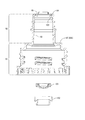
インクボトル62Bは、図17中のE−E線における分解断面図である図18に示すように、インク出口形成部65Bと、容器本体部67Bと、カバー141と、を含む。インク出口形成部65Bを構成する材料は、ポリプロピレンに限定されず、他の合成樹脂であってもよい。この点において、インク出口形成部65Bは、実施例1におけるインク出口形成部65Aと異なっている。この点を除いて、インク出口形成部65Bは、実施例1におけるインク出口形成部65Aと同様の構成を有している。なお、上記の差異を除いて、ボトルセット61Bは、実施例1のボトルセット61Aと同様の構成を有している。
The
容器本体部67Bは、外殻の形状が実施例1と異なることを除いて、実施例1における容器本体部67Aと同様の構成を有している。容器本体部67Bには、インク出口形成部65B側とは反対側の端部142、すなわち開口部84側とは反対側の端部142に、半球状の球面部143が形成されている。
The
ここで、実施例1の容器本体部67Aでは、底面部144(図8)と側壁145とをつなぐ角部146の強度を高めることが難しい。これは、合成樹脂材のブロー成形において、角部146の厚みが薄くなりやすいためである。なお、底面部144は、容器本体部67Aにおいて、開口部84に対向する面であり、底面部144を水平面に載置したときにインク収容部64の底に相当する部分である。側壁145は、底面部144に交差しており、底面部144側から端部83B側に向かって延伸する壁である。
Here, in the container
実施例1に対して、実施例2では、球面部143によって、実施例1における角部146を解消しやすい。このため、容器本体部67Bを構成する材料の厚みが薄くなることを抑制しやすい。この結果、容器本体部67Bの強度を高めることができる。なお、球面部143の形状は、厳密な半球に限定されず、容器本体部67Bを構成する材料の厚みが薄くなることが軽減できる範囲で歪んでいたり、いびつであったり、凹凸を含んでいたりしてもよい。
In contrast to the first embodiment, in the second embodiment, the
また、実施例2では、カバー141は、球面部143の少なくとも一部を覆っている。つまり、インクボトル62Bは、容器本体部67Bの少なくともインク出口形成部65Bと反対側の端部を覆うカバー141を備えている。これにより、カバー141で球面部143を保護することができるので、インクボトル62Bの強度を高めることができ、利便性や信頼性を向上させることができる。また、カバー141は、筒状の構造を有している。筒状のカバー141の内側に球面部143が挿入される。このため、筒状のカバー141によって、球面部143を下方に位置させた状態でインクボトル62Bを起立させることができる。なお、筒状のカバー141に球面部143が挿入された状態で、球面部143よりも端部83B側と反対側に、筒状のカバー141を塞ぐ塞壁147が設けられている。これにより、球面部143をカバー141で覆うことができる。
Further, in the second embodiment, the
また、実施例2では、カバー141の外径が、容器本体部67Bの外径と同等に設定されている。このため、カバー141の外周面と、容器本体部67Bの外周面とをそろえることができるので、ボトルセット61Bが大型化することを避けやすい。
Further, in the second embodiment, the outer diameter of the
(実施例3)
実施例3のボトルセット61Cについて説明する。実施例3において、実施例1や実施例2と同様の構成については、実施例1や実施例2と同一の符号を付して詳細な説明を省略する。実施例3のボトルセット61Cは、図19に示すように、インクボトル62Cと、蓋部材63Bと、を含む。蓋部材63Bは、実施例2と同一である。
(Example 3)
The bottle set 61C of the third embodiment will be described. In the third embodiment, the same configurations as those in the first and second embodiments are designated by the same reference numerals as those in the first and second embodiments, and detailed description thereof will be omitted. As shown in FIG. 19, the bottle set 61C of the third embodiment includes an
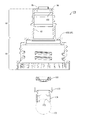
インクボトル62Cは、図19中のF−F線における分解断面図である図20に示すように、インク出口形成部65Bと、容器本体部67Cと、規制部材151と、カバー141と、を含む。インク出口形成部65Bは、実施例2と同様の構成を有している。実施例3では、容器本体部67Cが、第1部分152と、第2部分153と、含む。本実施例では、第1部分152と第2部分153とを組み合わせることによって容器本体部67Cが構成される。つまり、本実施例では、容器本体部67Cが、第1部分152と、第2部分153とに区分される。第1部分152は、可撓性を有している。
The
第1部分152は、容器本体部67Cのうちインク出口形成部65B側に位置する部位である。第2部分153は、容器本体部67Cのうちインク出口形成部65B側と反対側に位置する部位である。つまり、第1部分152は、容器本体部67Cの端部83Bの開口部84を含む部位である。第2部分153は、インク出口形成部65B側と反対側の端部142を含む部位である。
The
第1部分152は、筒状の構造を有している。第2部分153は、端部142が球面部143によって閉じられた筒状の構造を有している。筒状の第1部分152の内側に、第2部分153の端部142と反対側が挿入される。これにより、第1部分152と第2部分153とが組み合わされ、容器本体部67Cが構成される。なお、第1部分152と第2部分153とのつなぎ目を接着や溶着などによって接合すれば、容器本体部67Cの気密性を高めることができる。
The
規制部材151は、容器本体部67Cの内部に収容される。規制部材151は、主軸154を有している。主軸154は、容器本体部67Cの端部83Bと端部142とを結ぶ軸線、すなわち容器本体部67Cの延在方向に沿った軸線に沿っている。主軸154は、容器本体部67Cの内部に収まる長さを有している。規制部材151には、主軸154から、主軸154に交差する方向に延びる複数の腕部155を有している。腕部155の外径は、容器本体部67Cの内径よりも小さい。このため、容器本体部67C内に規制部材151を収容することができる。
The regulating
なお、規制部材151は、第1部分152と第2部分153とを容器本体部67Cとして組み合わせるときに、容器本体部67C内に収容される。つまり、第1部分152と第2部分153との間に規制部材151を配置した状態で、第1部分152と第2部分153とを組み合わせることによって、容器本体部67C内に規制部材151を収容することができる。
The regulating
なお、ボトルセット61Cの各部材(上述した、インク出口形成部65B、規制部材151等)は、別部材であるが、例えば、3Dプリンター等を用いて、ボトルセット61Cの全体または一部の複数の部材を、一体的に形成してもよい。
Each member of the bottle set 61C (the ink
実施例3において、カバー141の内側に球面部143が挿入される点は実施例2と同様である。上記により、図21に示すように、インクボトル62Cが構成される。実施例3においても、実施例2と同様の効果が得られる。
In the third embodiment, the point that the
また、実施例3のインクボトル62Cによれば、容器本体部67C内に規制部材151が設けられている。これにより、例えば、容器本体部67Cに圧搾力が作用したときに、容器本体部67Cの圧搾変形を規制部材151で規制することができるので、容器本体部67C内のインクが漏れ出ることを抑えやすい。このように、このインクボトル62Cでは、利便性を向上させやすい。
Further, according to the
また、実施例3では、容器本体部67Cにおいて、第2部分153の外径が、第1部分152の外径と同等以下に設定されている。このため、容器本体部67Cにおいて、第1部分152と第2部分153との外周面をそろえることができるので、ボトルセット61Cが大型化することを避けやすい。
Further, in the third embodiment, in the container
(実施例4)
実施例4のボトルセット61Dについて説明する。実施例4において、実施例1〜実施例3と同様の構成については、実施例1〜実施例3と同一の符号を付して詳細な説明を省略する。実施例4のボトルセット61Dは、図22に示すように、インクボトル62Dと、蓋部材63Bと、を含む。蓋部材63Bは、実施例2と同一である。
(Example 4)
The bottle set 61D of the fourth embodiment will be described. In the fourth embodiment, the same configurations as those in the first to third embodiments are designated by the same reference numerals as those in the first to third embodiments, and detailed description thereof will be omitted. As shown in FIG. 22, the bottle set 61D of the fourth embodiment includes an
インクボトル62Dは、図22中のG−G線における分解断面図である図23に示すように、インク出口形成部65Bと、容器本体部67Dと、カバー161と、を含む。インク出口形成部65Bは、実施例2と同様の構成を有している。
The
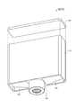
容器本体部67Dは、端部142に開口162が形成されている。容器本体部67Dは、インクを収容可能な空間であるインク収容部64と、インク収容部64に外部から大気を導入可能な開口162とを備えている。この点を除いて、容器本体部67Dは、実施例2と同様の構成を有している。カバー161は、塞壁147に開口164が形成されていること、及び閉塞部165を有することを除いて、実施例2と同様の構成を有している。
The
容器本体部67Dにおいて、開口162は、球面部143から端部83B側と反対側に向かって突出する筒部163に形成されている。開口162は、球面部143から突出する筒部163の球面部143側と反対側の端部142に形成されている。
In the
カバー161の塞壁147において、開口164は、筒状のカバー161の内側に球面部143が挿入された状態で、容器本体部67Dの筒部163に対向する位置に形成されている。開口164は、筒部163を受容可能な大きさ及び形状に形成されている。よって、図24に示すように、筒状のカバー161の内側に球面部143が挿入された状態で、容器本体部67Dの開口162がカバー161の開口164を介して露出し得る。なお、図24では、図22中のH部をG−G線で切断したときの断面が示されている。
In the
閉塞部165は、容器本体部67Dの開口162を閉塞可能なキャップ状の部材である。閉塞部165は、カバー161の開口164内で容器本体部67Dの開口162に臨んで位置している。なお、閉塞部165は、カバー161に連結されている。これにより、閉塞部165が紛失することを避けやすい。閉塞部165は、容器本体部67Dの開口162を開閉自在に閉塞する。本実施例では、閉塞部165は、容器本体部67Dの筒部163の外側に挿入される。これにより、容器本体部67Dの筒部163の端部142が閉塞部165によって覆われる。この結果、容器本体部67Dの開口162が閉塞部165によって塞がれる。また、閉塞部165を筒部163から外せば、容器本体部67Dの開口162が開放される。なお、本実施例では、閉塞部165がカバー161に連結されているが、閉塞部165が容器本体部67Dに連結された構成も採用され得る。さらに、閉塞部165が他の構成部材に連結されず、閉塞部165が独立した構成も採用され得る。
The closing
実施例4においても、実施例2と同様の効果が得られる。さらに、実施例4では、容器本体部67Dに開口162が形成されている。また、実施例4では、容器本体部67Dに形成された開口162を開閉自在に閉塞する閉塞部165が設けられている。このため、例えば、容器本体部67D内のインクをインク出口95から流出させるときに閉塞部165による開口162の閉塞を解除することによって、すなわち容器本体部67D内のインクをインク出口95から流出させるときに開口162を開放することによって、開口162を介して外部の大気を容器本体部67D内に導入することができる。これにより、容器本体部67D内のインクをインク出口95から速やかに流出させることができる。このように、このインクボトル62Dでは、利便性を向上させやすい。
In Example 4, the same effect as in Example 2 can be obtained. Further, in the fourth embodiment, an
また、カバー161には、図24に示すように、陥没部166が設けられている。陥没部166は、カバー161の塞壁147の容器本体部67D側と反対側に設けられている。陥没部166は、カバー161の端部167と塞壁147との間の空間の領域である。この構成により、インクボトル62Dは、外殻の一部が陥没した陥没部166を有しているとみなされ得る。インクボトル62Dにおいて、陥没部166は、端部167から容器本体部67D側に向かって凹となる向きに設けられている。そして、容器本体部67Dの開口162が、陥没部166に位置している。つまり、開口162が陥没部166に形成されている。このため、開口162は、インクボトル62Dの外殻から没する位置にある。これにより、開口162を閉塞する閉塞部165の少なくとも一部分を陥没部166内に納めることができるので、閉塞部165がインクボトル62Dの外殻から突出する量を軽減することができる。また、開口162が、陥没部166に位置することにより、不用意な外力が閉塞部165に作用し、閉塞部165が開口162から外れることを防止できる。
Further, as shown in FIG. 24, the
また、実施例4では、開口162が、容器本体部67Dのインク出口形成部65Bと反対側の端部142に形成されている。このため、インク出口95を下に向けてインクボトル62Dを傾倒させてインクをインク出口95から流出させるときに、開口162がインク出口95よりも上方に位置する。このため、インク出口95を下に向けてインクボトル62Dを傾倒させてインクをインク出口95から流出させるときに、インクボトル62D内のインクが開口162よりも下方に位置しやすい。つまり、インク出口95を下に向けてインクボトル62Dを傾倒させてインクをインク出口95から流出させるときに、インクボトル62D内のインクの液面が開口162よりも下方に位置しやすい。よって、開口162からインクが漏れにくい。
Further, in the fourth embodiment, the
なお、実施例3に実施例4の構成を適用することもできる。この場合、第2部分153に筒部163と開口162が形成され、カバー141に替えてカバー161が採用される。
The configuration of the fourth embodiment can also be applied to the third embodiment. In this case, the
(実施例5)
実施例5のボトルセット61Eについて説明する。実施例5において、実施例1〜実施例4と同様の構成については、実施例1〜実施例4と同一の符号を付して詳細な説明を省略する。実施例5のボトルセット61Eは、図25に示すように、インクボトル62Eと、蓋部材63Bと、を含む。蓋部材63Bは、実施例2と同一である。なお、図25では、ボトルセット61Eを図6に示すB−B線に相当する線で切断したときの断面が示されている。
(Example 5)
The bottle set 61E of the fifth embodiment will be described. In the fifth embodiment, the same configurations as those in the first to fourth embodiments are designated by the same reference numerals as those in the first to fourth embodiments, and detailed description thereof will be omitted. As shown in FIG. 25, the bottle set 61E of the fifth embodiment includes an
インクボトル62Eは、インク出口ユニット171と、容器本体部67Bと、撹拌部材172と、カバー141と、を含む。容器本体部67B、及びカバー141は、実施例2と同一である。インクボトル62Eは、実施例2のホルダー102(図10)が後述するホルダー173に置換され、且つ撹拌部材172が付加されたことを除いて、実施例2と同様の構成を有している。
The
撹拌部材172は、容器本体部67B内、すなわちインク収容部64に収容される。インクボトル62Eを振動させると、撹拌部材172がインク収容部64内で変位するので、インク収容部64内のインクを撹拌することができる。インクボトル62Eに好適なインクとして、例えば、顔料インクが挙げられる。顔料インクは、色材として粉末状の原料が採用される。顔料インクは、顔料の粒子を液体に分散させた構成を有している。顔料を分散させる液体は、分散媒とも呼ばれる。分散媒としては、油性や水性等の分散媒が採用され得る。
The stirring
顔料インクでは、インク収容部64内で顔料が分散媒中に沈降(沈殿ともいう)することがある。このような場合に、インクボトル62Eに振動を与えれば顔料インクを撹拌することができるので好ましい。なお、この場合、撹拌部材172の材料としては、顔料インクの密度よりも高い密度を有する材料が好ましい。これは、顔料インク中に撹拌部材172が沈みやすいので、撹拌の効果を高めやすいためである。
In the pigment ink, the pigment may settle (also referred to as precipitation) in the dispersion medium in the
インクボトル62Eでは、インク出口ユニット171が採用されている。インク出口ユニット171は、図26に示すように、インク出口形成部65Bと、弁101と、ホルダー173と、を含む。なお、実施例1〜実施例4のインク出口形成部65と、弁101と、ホルダー102との組み合わせもインク出口ユニット171と呼ぶことがある。実施例5のインク出口ユニット171は、実施例2のホルダー102(図10)がホルダー173に置換されていることを除いて、実施例2のインク出口ユニット171と同様の構成を有している。
In the
ホルダー173には、図26に示すように、筒部174に溝175が形成されている。筒部174は、円筒状の外観を有しており、インク出口形成部65Bの導出流路93内においてインク出口95と反対側に向かって延びている。溝(本発明における、開口部)175は、筒部174の延在方向に沿って形成されている。筒部174に溝175が設けられているので、筒部174が撹拌部材172によって塞がれても、インク収容部64内のインクが溝175を介してインク出口95に流通することができる。これにより、インクボトル62E内のインクをインク出口95から速やかに流出させることができる。このように、このインクボトル62Eでは、利便性を向上させやすい。本実施形態では、2つの溝175が形成されているため、1つの溝をインクが通過し、もう一つの溝を空気が通過し、インクボトル62E内部の気液交換がより円滑に行われ、インクボトル内部から外部へインクをより円滑に排出することができる。
As shown in FIG. 26, the
なお、開口部については、敢えて、図示はしないが、筒部の延在方向に沿って形成されている溝175に限らず、筒部の導出流路の重力方向と交差する方向に開口部を形成してもよい。また、開口部の数、大きさ、位置については、本実施形態に限らない。
Although not shown, the opening is not limited to the
なお、撹拌部材172は、球形に限定されない。撹拌部材172の形状としては、楕円体、多面体など、種々の形状が採用され得る。また、実施例1〜実施例4のそれぞれに撹拌部材172を適用した構成も採用され得る。この場合、ホルダー173を備えたインク出口ユニット171を採用する構成が好ましい。
The stirring
(実施例6)
実施例6のボトルセット61Fについて説明する。実施例6において、実施例1〜実施例5と同様の構成については、実施例1〜実施例5と同一の符号を付して詳細な説明を省略する。実施例6のボトルセット61Fは、図27に示すように、インクボトル62Fと、蓋部材63Bと、を含む。蓋部材63Bは、実施例2と同一である。
(Example 6)
The bottle set 61F of the sixth embodiment will be described. In the sixth embodiment, the same configurations as those in the first to fifth embodiments are designated by the same reference numerals as those in the first to fifth embodiments, and detailed description thereof will be omitted. As shown in FIG. 27, the bottle set 61F of the sixth embodiment includes an
インクボトル62Fは、図27中のJ−J線における分解断面図である図28に示すように、インク出口形成部65Cと、弁101と、ホルダー102と、フィルム181と、容器本体部67Bと、カバー141と、を含む。容器本体部67B、弁101、ホルダー102、及びカバー141は、実施例2と同一である。
As shown in FIG. 28, which is an exploded cross-sectional view taken along the line JJ in FIG. 27, the
フィルム181は、柔軟性を有し、容器本体部67Bの開口部84を覆う大きさ及び形状を有している。フィルム181は、開口部84の端部83Bに接合され、開口部84を封止している。ノズル部材の一例であるインク出口形成部65Cは、破砕部182を有している。この点を除いて、インク出口形成部65Cは、実施例2のインク出口形成部65Bと同様の構成を有している。インクボトル62Fは、フィルム181が付加されている点、及びインク出口形成部65Bがインク出口形成部65Cに置換されている点を除いて、実施例2と同様の構成を有している。
The
フィルム181は、例えば、ポリエチレンテレフタレート(PET)、ナイロン、ポリエチレンなどの材料で形成され得る。また、これらの材料を積層した積層構造も採用され得る。さらに、これらの材料にアルミニウムなどを蒸着した層を有する構成も採用され得る。これにより、ガスバリア性を高めることができる。フィルム181は、例えば、溶着により容器本体部67Bの端部83Bに接合される。これにより、容器本体部67B内の液密性が高く保たれ、インクを容器本体部67Bに密封することができる。ボトルセット61Fを使用する利用者は、ボトルセット61F内のインクをインクタンク31に注入する前に、容器本体部67Bからフィルム181を開封してから注入を実施する。
The
インク出口形成部65Cの破砕部182は、図29に示すように、筒部92をインク出口形成部65Cの端部183側に延長した形態を有している。なお、図29では、インク出口形成部65Cを図27中のJ−J線で切断したときの断面が示されている。端部183は、インク出口形成部65Cの端面94側と反対側に位置する端縁である。インク出口形成部65Cでは、筒部92が結合部91内に延長されているともみなされ得る。なお、破砕部182は、筒部92の結合部91内に延長された部分であり、結合部91内に位置する部分である。
As shown in FIG. 29, the crushed
破砕部182は、図30に示すように、結合部91に設けられた筒状の外観を有している。筒状の破砕部182の内側は、図29に示すように、導出流路93につながっている。インク出口形成部65Cでは、導出流路93が結合部91内に延長されているともみなされ得る。筒状の破砕部182には、図30に示すように、少なくとも2つの刃部184が設けられている。
As shown in FIG. 30, the crushed
図28に示すインク出口形成部65Cのねじ81と容器本体部67Bのねじ69とを係合させてインク出口形成部65Cを容器本体部67Bに装着した状態で、破砕部182は、容器本体部67Bの開口部84よりもインク収容部64側に進入する。このため、フィルム181を開封する前の状態でインク出口形成部65Cを容器本体部67Bに装着すると、図31に示すように、破砕部182がフィルム181を突き破る。これにより、容器本体部67Bに付されたフィルム181を開封することができる。このため、作業者にフィルム181を容器本体部67Bから剥離させることなく、インク出口形成部65Cを容器本体部67Bに装着させるだけでフィルム181を開封することができる。これにより、インクボトル62Fの利便性を向上させやすい。
In a state where the
上述したように、破砕部182には、少なくとも2つの刃部184が設けられているので、インク出口形成部65Cを容器本体部67Bに装着したときに、フィルム181には、少なくとも2箇所の破断部が形成される。フィルム181に2箇所の破断部が形成されると、例えば、インクをインク出口95から流出させるとき、2箇所の破断部のうちの1つの破断部を介してインクをインク出口95から流出させ、2箇所の破断部のうちの他の破断部を介して外部の大気をインク収容部64内に導入することができる。つまり、2箇所の破断部の一方をインクの流通に活用し、他方を大気の流通に活用することができる。これにより、容器本体部67B内のインクをインク出口95から速やかに流出させることができるので、インクボトル62Fの利便性を向上させやすい。なお、破砕部182において、刃部184の個数は2つに限定されず、3つや3つを超える個数も採用され得る。
As described above, since the crushing
上述した実施例1〜実施例6では、インクボトル62が円柱状の外観を有しているが、インクボトル62の外観は、これに限定されない。インクボトル62の外観としては、三角柱状や直方体状等の多角柱状、楕円柱状、異形柱状など、種々の外観が採用され得る。また、インクボトル62の外観は、柱状に限定されず、箱状、球状など、種々の形状が採用され得る。以下に、直方体状の外観を有するインクボトル62の実施例を説明する。以下の実施例において、実施例1〜実施例6と同様の機能を有する構成や、実施例1〜実施例6と同一の構成については、実施例1〜実施例6の構成と同一の符号を付して詳細な説明を省略する。
In Examples 1 to 6 described above, the
(実施例7)
実施例7のインクボトル62Gは、図32に示すように、容器本体部191と、蓋部材192と、を含む。容器本体部191は、直方体状の外観を有しており、容器状に形成されている。容器状の容器本体部191の底に相当する底壁193には、インク出口形成部194が形成されている。インク出口形成部194は、インク出口形成部65と同様の機能を有している。蓋部材192は、容器状の容器本体部191の蓋に相当する部分であり、底壁193に相対する。
(Example 7)
As shown in FIG. 32, the
容器本体部191と蓋部材192とは、例えば、ポリエチレンテレフタレート(PET)、ナイロン、ポリエチレン、ポリプロピレン、ポリスチレンなどの樹脂材料や、鉄材やアルミニウム等の金属材料などで形成され得る。容器本体部191において、底壁193とインク出口形成部194とは、互いに一体に形成されている。
The
また、インクボトル62Gは、図33に示すように、弁101と、ホルダー102と、を有している。弁101、及びホルダー102は、実施例1と同一である。容器本体部191と蓋部材192とによって囲まれた領域がインク収容部64を構成している。実施例7のインクボトル62Gにおいても、インクを収容することができる。インクボトル62Gに収容されたインクは、インク出口形成部194を介して、インク供給装置4(図2)のインクタンク31に供給され得る。
Further, as shown in FIG. 33, the
(実施例8)
実施例8のインクボトル62Hは、図34に示すように、規制部材195を有している。このことを除いて、実施例8のインクボトル62Hは、実施例7と同一の構成を有している。規制部材195は、実施例3の規制部材151(図20)と同様の機能を有する。規制部材195は、図34に示すように、インク収容部64内に収容されている。実施例8においても、実施例3と同様の効果が得られる。
(Example 8)
The
上記各実施形態や各実施例において、インク噴射装置は、インク以外の他の液体を噴射したり吐出したり塗布したりして消費する液体噴射装置であってもよい。なお、液体噴射装置から微小量の液滴となって吐出される液体の状態としては、粒状、涙状、糸状に尾を引くものも含むものとする。また、ここでいう液体は、液体噴射装置で消費させることができるような材料であればよい。例えば、物質が液相であるときの状態のものであればよく、粘性の高い又は低い液状体、ゾル、ゲル水、その他の無機溶剤、有機溶剤、溶液、液状樹脂、液状金属(金属融液)のような流状体を含むものとする。また、物質の一状態としての液体のみならず、顔料や金属粒子などの固形物からなる機能材料の粒子が溶媒に溶解、分散又は混合されたものなども含むものとする。液体の代表的な例としては、上記各実施形態で説明したようなインクの他、液晶等も挙げられる。ここで、インクとは一般的な水性インク及び油性インク並びにジェルインク、ホットメルトインク等の各種液体組成物を包含するものとする。液体噴射装置の具体例としては、例えば、液晶ディスプレイ、EL(エレクトロルミネッセンス)ディスプレイ、面発光ディスプレイ、カラーフィルターの製造等に用いられる電極材や色材等の材料を分散又は溶解のかたちで含む液体を噴射する液体噴射装置がある。また、バイオチップ製造に用いられる生体有機物を噴射する液体噴射装置、精密ピペットとして用いられ試料となる液体を噴射する液体噴射装置、捺染装置やマイクロディスペンサー等であってもよい。さらに、時計やカメラ等の精密機械にピンポイントで潤滑油を噴射する液体噴射装置、光通信素子等に用いられる微小半球レンズ(光学レンズ)などを形成するために紫外線硬化樹脂等の透明樹脂液を基板上に噴射する液体噴射装置であってもよい。また、基板などをエッチングするために酸又はアルカリ等のエッチング液を噴射する液体噴射装置であってもよい。 In each of the above-described embodiments and examples, the ink injection device may be a liquid injection device that injects, ejects, or applies a liquid other than ink to consume. The state of the liquid discharged as a minute amount of droplets from the liquid injection device includes those having a granular, tear-like, or thread-like tail. Further, the liquid referred to here may be any material that can be consumed by the liquid injection device. For example, the substance may be in a liquid phase, and may be a highly viscous or low-viscosity liquid, sol, gel water, other inorganic solvents, organic solvents, solutions, liquid resins, liquid metals (metal melts). ) Is included. Further, it includes not only a liquid as a state of a substance but also a particle of a functional material made of a solid substance such as a pigment or a metal particle dissolved, dispersed or mixed in a solvent. Typical examples of the liquid include liquid crystals and the like in addition to the inks described in the above embodiments. Here, the ink includes general water-based inks, oil-based inks, and various liquid compositions such as gel inks and hot melt inks. Specific examples of the liquid injection device include liquids containing materials such as electrode materials and color materials used in the manufacture of liquid crystal displays, EL (electroluminescence) displays, surface emitting displays, color filters, etc. in the form of dispersion or dissolution. There is a liquid injection device that injects. Further, a liquid injection device for injecting a bioorganic substance used for producing a biochip, a liquid injection device for injecting a liquid as a sample used as a precision pipette, a printing device, a microdispenser, or the like may be used. Furthermore, a transparent resin liquid such as an ultraviolet curable resin is used to form a liquid injection device that injects lubricating oil pinpointly into precision machinery such as watches and cameras, and a microhemispherical lens (optical lens) used for optical communication elements. May be a liquid injection device that injects the liquid onto the substrate. Further, it may be a liquid injection device that injects an etching solution such as an acid or an alkali to etch a substrate or the like.
なお、本発明は、上述の実施形態や実施例に限られるものではなく、その趣旨を逸脱しない範囲において種々の構成で実現することができる。例えば、発明の概要の欄に記載した各形態中の技術的特徴に対応する実施形態、実施例中の技術的特徴は、上述の課題の一部又は全部を解決するために、あるいは、上述の効果の一部又は全部を達成するために、適宜、差し替えや、組み合わせを行うことが可能である。また、その技術的特徴が本明細書中に必須なものとして説明されていなければ、適宜、削除することが可能である。上記実施形態において、ボトルについては、弾性を有する材料であるが、ボトルの全体または一部を、ガラス、陶器、金属等の他の材料により形成されるようにしてもよい。 The present invention is not limited to the above-described embodiments and examples, and can be realized with various configurations within a range not deviating from the gist thereof. For example, the embodiment corresponding to the technical feature in each embodiment described in the column of the outline of the invention, the technical feature in the embodiment may be used to solve a part or all of the above-mentioned problems, or the above-mentioned above. It is possible to replace or combine them as appropriate to achieve some or all of the effects. Further, if the technical feature is not described as essential in the present specification, it can be deleted as appropriate. In the above embodiment, the bottle is made of an elastic material, but the whole or a part of the bottle may be made of other materials such as glass, pottery, and metal.
1…インク噴射システム、3…プリンター、4…インク供給装置、19…記録ヘッド、31…インクタンク、33…インク注入部、61,61A,61B,61C,61D,61E,61F…ボトルセット、62,62A,62B,62C,62D,62E,62F,62G,62H…インクボトル、63,63A,63B…蓋部材、64…インク収容部、65,65A,65B,65C…インク出口形成部、67,67A,67B,67C,67D…容器本体部、95…インク出口、101…弁、141…カバー、142…端部、143…球面部、144…底面部、151…規制部材、161…カバー、162…開口、165…閉塞部、166…陥没部、172…撹拌部材、181…フィルム、182…破砕部、P…記録媒体。 1 ... Ink injection system, 3 ... Printer, 4 ... Ink supply device, 19 ... Recording head, 31 ... Ink tank, 33 ... Ink injection unit, 61, 61A, 61B, 61C, 61D, 61E, 61F ... Bottle set, 62 , 62A, 62B, 62C, 62D, 62E, 62F, 62G, 62H ... Ink bottle, 63, 63A, 63B ... Lid member, 64 ... Ink storage part, 65, 65A, 65B, 65C ... Ink outlet forming part, 67, 67A, 67B, 67C, 67D ... Container body, 95 ... Ink outlet, 101 ... Valve, 141 ... Cover, 142 ... End, 143 ... Spherical part, 144 ... Bottom part, 151 ... Regulatory member, 161 ... Cover, 162 ... Opening, 165 ... Closing part, 166 ... Depressed part, 172 ... Stirring member, 181 ... Film, 182 ... Crushing part, P ... Recording medium.
Claims (8)
トルであって、
第1端部と、前記第1端部と反対側の第2端部とを有し、前記第1端部に開口部が設けら
れ、前記第2端部は閉じられた壁を形成し、前記第1端部と前記第2端部との間に筒状の
胴部を有し、インクを収容可能に構成された容器本体部と、
前記容器本体部の前記第1端部側にねじ部を介して着脱可能に係合する結合部と、前記
開口部と連通しインク導出流路を形成する筒部と、を有し、前記筒部の前記結合部側とは
反対側の端面にインク出口が設けられたインク出口形成部と、
を備え、
前記容器本体部は、前記第2端部側を覆うカバーを備え、
前記カバーは、筒状部分と、前記筒状部分を塞ぎ底を形成する塞壁とを有し、前記容
器本体部の前記第2端部側が前記カバー内に挿入された状態で前記筒状部分の外周面と前
記容器本体部の前記胴部の外周面とがそろうように形成されている、インクボトル。 An ink box for injecting ink into the ink tank via the connecting pipe of the ink tank.
It ’s a tor,
It has a first end and a second end opposite to the first end, and an opening is provided at the first end.
The second end forms a closed wall, and is tubular between the first end and the second end.
A container body that has a body and is configured to store ink,
A joint portion that is detachably engaged with the first end portion side of the container body portion via a screw portion, and the above.
It has a cylinder portion that forms a communication ink outlet flow path with the opening portion, and the joint portion side of the cylinder portion is
An ink outlet forming portion provided with an ink outlet on the opposite end face, and an ink outlet forming portion.
With
The container main body includes a cover that covers the second end side.
The cover has a tubular portion and a closing wall that closes the tubular portion and forms a bottom.
The outer peripheral surface and the front of the tubular portion with the second end side of the vessel body inserted into the cover.
An ink bottle formed so as to be aligned with the outer peripheral surface of the body of the container body.
り形成されている、インクボトル。 The ink bottle according to claim 1, wherein the container body is blow-molded with a synthetic resin.
Ink bottle that is formed.
部側は球面を有する、インクボトル。 The second end of the container body of the ink bottle according to claim 1 or 2.
An ink bottle with a spherical surface on the part side.
部は、前記インク導出流路に設けられた弁を備え、前記筒部は、前記筒部の内側面から内
径方向に延伸するフランジ部を有し、前記弁は、前記フランジ部の内側に接して設けられ
た弾性材から成る弁であり、前記インク出口形成部から分離可能に構成された、インクボ
トル。 The ink bottle according to any one of claims 1 to 3, wherein the ink outlet is formed.
The portion includes a valve provided in the ink lead-out flow path, and the tubular portion is from the inner side surface to the inner side of the tubular portion.
It has a flange portion that extends in the radial direction, and the valve is provided in contact with the inside of the flange portion.
An ink bottle which is a valve made of an elastic material and is configured to be separable from the ink outlet forming portion.
口形成部の前記結合部側から挿入されて装着されており、且つ、前記弁は前記フランジ部
と前記ホルダーとによって挟持される、インクボトル。 The ink bottle according to claim 4, wherein the valve is held in a holder and the ink is discharged.
The valve is inserted and mounted from the joint portion side of the mouth forming portion, and the valve is the flange portion.
An ink bottle sandwiched between the holder and the holder.
部は、前記結合部側から前記端面側に向けて突出する複数の位置決め部を有し、前記複数
の位置決め部は、前記インク出口の中心軸に対して点対称に配置され、前記インクタンク
側に前記接続管を中心として点対称に配置されたスロット部に挿入可能に構成された、イ
ンクボトル。 The ink bottle according to any one of claims 1 to 5, wherein the ink outlet is formed.
The portion has a plurality of positioning portions protruding from the joint portion side toward the end face side, and the plurality of portions
The positioning portion of is arranged point-symmetrically with respect to the central axis of the ink outlet, and the ink tank is
An ink bottle configured to be insertable into a slot portion arranged point-symmetrically with respect to the connection tube on the side.
記スロット部に設けられた凸部と適合する場合前記スロット部に挿入可能となる鍵として
機能する、インクボトル。 The ink bottle according to claim 6, wherein the positioning portion has a recess, and the recess is in front.
As a key that can be inserted into the slot when it matches the convex part provided in the slot
A working ink bottle.
方体状の外観を有する、インクボトル。 The ink bottle according to any one of claims 1 to 7, wherein the container body is directly formed.
An ink bottle with a square appearance.
Priority Applications (8)
| Application Number | Priority Date | Filing Date | Title |
|---|---|---|---|
| JP2017011876A JP6907559B2 (en) | 2017-01-26 | 2017-01-26 | Ink bottle |
| CN201820026276.0U CN208180536U (en) | 2017-01-26 | 2018-01-08 | Ink bottle and bottle cover part |
| US15/879,184 US20180207939A1 (en) | 2017-01-26 | 2018-01-24 | Ink bottle and bottle set |
| US16/728,430 US11192380B2 (en) | 2017-01-26 | 2019-12-27 | Ink bottle and bottle set |
| JP2021107556A JP7140240B2 (en) | 2017-01-26 | 2021-06-29 | Ink bottle, bottle set |
| US17/516,904 US11597207B2 (en) | 2017-01-26 | 2021-11-02 | Ink bottle and bottle set |
| JP2022141213A JP7363998B2 (en) | 2017-01-26 | 2022-09-06 | ink bottle, bottle set |
| US18/104,849 US11932022B2 (en) | 2017-01-26 | 2023-02-02 | Ink bottle and bottle set |
Applications Claiming Priority (1)
| Application Number | Priority Date | Filing Date | Title |
|---|---|---|---|
| JP2017011876A JP6907559B2 (en) | 2017-01-26 | 2017-01-26 | Ink bottle |
Related Child Applications (1)
| Application Number | Title | Priority Date | Filing Date |
|---|---|---|---|
| JP2021107556A Division JP7140240B2 (en) | 2017-01-26 | 2021-06-29 | Ink bottle, bottle set |
Publications (3)
| Publication Number | Publication Date |
|---|---|
| JP2018118453A JP2018118453A (en) | 2018-08-02 |
| JP2018118453A5 JP2018118453A5 (en) | 2020-01-16 |
| JP6907559B2 true JP6907559B2 (en) | 2021-07-21 |
Family
ID=62905514
Family Applications (3)
| Application Number | Title | Priority Date | Filing Date |
|---|---|---|---|
| JP2017011876A Active JP6907559B2 (en) | 2017-01-26 | 2017-01-26 | Ink bottle |
| JP2021107556A Active JP7140240B2 (en) | 2017-01-26 | 2021-06-29 | Ink bottle, bottle set |
| JP2022141213A Active JP7363998B2 (en) | 2017-01-26 | 2022-09-06 | ink bottle, bottle set |
Family Applications After (2)
| Application Number | Title | Priority Date | Filing Date |
|---|---|---|---|
| JP2021107556A Active JP7140240B2 (en) | 2017-01-26 | 2021-06-29 | Ink bottle, bottle set |
| JP2022141213A Active JP7363998B2 (en) | 2017-01-26 | 2022-09-06 | ink bottle, bottle set |
Country Status (3)
| Country | Link |
|---|---|
| US (4) | US20180207939A1 (en) |
| JP (3) | JP6907559B2 (en) |
| CN (1) | CN208180536U (en) |
Families Citing this family (20)
| Publication number | Priority date | Publication date | Assignee | Title |
|---|---|---|---|---|
| US9421781B2 (en) * | 2012-10-15 | 2016-08-23 | Seiko Epson Corporation | Recording apparatus |
| CN107487084B (en) | 2016-06-10 | 2020-08-14 | 精工爱普生株式会社 | Ink replenishing container |
| CN207291315U (en) | 2016-06-10 | 2018-05-01 | 精工爱普生株式会社 | Ink replenishing container and ink replenishing system |
| TWI774588B (en) | 2016-06-10 | 2022-08-11 | 日商精工愛普生股份有限公司 | ink supply container |
| US10350901B2 (en) | 2016-06-10 | 2019-07-16 | Seiko Epson Corporation | Ink bottle |
| JP6907559B2 (en) * | 2017-01-26 | 2021-07-21 | セイコーエプソン株式会社 | Ink bottle |
| USD849532S1 (en) * | 2018-02-26 | 2019-05-28 | Seiko Epson Corporation | Packaging container |
| JP7183810B2 (en) | 2019-01-24 | 2022-12-06 | セイコーエプソン株式会社 | Ink supply container and ink supply system |
| JP7163790B2 (en) | 2019-01-24 | 2022-11-01 | セイコーエプソン株式会社 | Ink supply container and ink supply system |
| JP7247606B2 (en) * | 2019-01-30 | 2023-03-29 | セイコーエプソン株式会社 | Ink supply container |
| JP7205295B2 (en) * | 2019-02-27 | 2023-01-17 | セイコーエプソン株式会社 | liquid container |
| CN111746126B (en) * | 2019-03-29 | 2022-02-15 | 珠海纳思达企业管理有限公司 | A kind of container |
| CN110014742B (en) * | 2019-04-12 | 2020-12-08 | 浙江昌新生物纤维股份有限公司 | Adopt split type ink horn of repeatedly filling of parallel steering principle |
| JP6987923B2 (en) * | 2019-08-27 | 2022-01-05 | キヤノン株式会社 | Liquid refill system |
| JP7404826B2 (en) * | 2019-11-29 | 2023-12-26 | セイコーエプソン株式会社 | Ink supply container set, ink supply container, and its packaging |
| WO2021131471A1 (en) | 2019-12-26 | 2021-07-01 | ローランドディー.ジー.株式会社 | Inkjet printer |
| JP7497628B2 (en) | 2020-07-03 | 2024-06-11 | セイコーエプソン株式会社 | Ink refill container |
| JP7497630B2 (en) | 2020-07-07 | 2024-06-11 | セイコーエプソン株式会社 | Ink supply container and method for remanufacturing same |
| JP2022129862A (en) * | 2021-02-25 | 2022-09-06 | キヤノン株式会社 | Liquid supplementing container to supplement liquid to liquid discharge device and reuse system using the same |
| CN113335754A (en) * | 2021-07-16 | 2021-09-03 | 传美讯电子科技(珠海)有限公司 | Leakage-proof bottle plug and ink bottle structure |
Family Cites Families (145)
| Publication number | Priority date | Publication date | Assignee | Title |
|---|---|---|---|---|
| US313253A (en) * | 1885-03-03 | thatchee | ||
| US811811A (en) * | 1905-05-22 | 1906-02-06 | James J Allison | Stopper for bottles. |
| US3179276A (en) * | 1963-11-26 | 1965-04-20 | Gillette Co | Container nozzle and cap |
| US3893596A (en) * | 1974-02-25 | 1975-07-08 | Vca Corp | Upright-inverted aerosol dispenser |
| US4243150A (en) * | 1978-01-23 | 1981-01-06 | Siemens Aktiengesellschaft | Bottle seal |
| GB2080775B (en) | 1980-06-09 | 1983-11-09 | Baxter Travenol Lab | Plastics container and closure device |
| JPS58107348A (en) | 1981-12-19 | 1983-06-27 | Ricoh Co Ltd | Ink bottle for ink jet recorder |
| JPS5942963A (en) | 1982-09-03 | 1984-03-09 | Ricoh Co Ltd | Bottle for waste liquid |
| USRE32142E (en) * | 1982-09-13 | 1986-05-13 | Method and apparatus for making carbonated beverages | |
| US4548828A (en) * | 1982-09-13 | 1985-10-22 | Meyers Louis B | Method for making carbonated beverages |
| US4801054A (en) * | 1987-07-06 | 1989-01-31 | Owens-Illinois Closure Inc. | Watertight molded plastic dispensing closure |
| US5343226A (en) * | 1990-09-28 | 1994-08-30 | Dataproducts Corporation | Ink jet ink supply apparatus |
| JPH0738156Y2 (en) * | 1991-03-13 | 1995-08-30 | ダイナボット株式会社 | Tight-sealed structure of cryogenic storage container |
| US5874976A (en) | 1996-10-07 | 1999-02-23 | Hewlett-Packard Company | Inkjet cartridge fill port adapter |
| GB9205870D0 (en) * | 1992-03-18 | 1992-04-29 | Willett Int Ltd | Replenishment of reservoirs |
| US5379927A (en) * | 1994-03-11 | 1995-01-10 | Loctite Corporation | New Package for instant adhesives |
| US5595223A (en) | 1994-10-21 | 1997-01-21 | Mitsubishi Pencil Corporation Of America | Ink refilling assembly |
| US5531353A (en) * | 1994-10-26 | 1996-07-02 | Ward; Ronald K. | Drinking cup device |
| JPH0920018A (en) | 1995-07-06 | 1997-01-21 | Brother Ind Ltd | Ink cartridge and ink jet recording device |
| JP3021835U (en) | 1995-08-23 | 1996-03-12 | 株式会社永谷園 | Can container |
| USD398634S (en) | 1995-10-17 | 1998-09-22 | Fuji Xerox Co., Ltd. | Toner cartridge |
| US5838352A (en) * | 1995-11-24 | 1998-11-17 | Smith Corona Corporation | Ink cartridge refilling device and station for cartridges and gravity feed ink bottle |
| JP3676876B2 (en) * | 1996-05-07 | 2005-07-27 | 三菱鉛筆株式会社 | Applicator with valve |
| US5903293A (en) * | 1996-05-20 | 1999-05-11 | Graphic Controls Corporation | Ink-jet bottle and valve system |
| GB9623544D0 (en) * | 1996-11-12 | 1997-01-08 | Micromass Ltd | Sample vial and vial closure device for use in gas analysis and method of using the same |
| JPH10216612A (en) * | 1997-02-12 | 1998-08-18 | Pilot Corp:The | Coating application implement |
| JP3523021B2 (en) * | 1997-06-20 | 2004-04-26 | 株式会社吉野工業所 | Container |
| US6079823A (en) * | 1997-07-23 | 2000-06-27 | Marconi Data Systems Inc. | Ink bottle with puncturable diaphragm closure |
| US5783254A (en) * | 1997-09-29 | 1998-07-21 | Maynard; Robert G. | Paint applicator method |
| JP3342372B2 (en) * | 1997-10-23 | 2002-11-05 | キヤノン株式会社 | Large-capacity ink refill containers used in inkjet printing systems |
| US7326234B2 (en) * | 1998-12-10 | 2008-02-05 | Playtex Products, Inc. | Vented bottle |
| US6209736B1 (en) * | 1999-06-08 | 2001-04-03 | Pin-Nan Chen | Structure of feeding bottle |
| JP2001002097A (en) | 1999-06-17 | 2001-01-09 | Yoshino Kogyosho Co Ltd | Bottle body |
| JP2001088317A (en) | 1999-09-20 | 2001-04-03 | Toshiba Tec Corp | Ink bottle, and ink supply apparatus |
| US6164768A (en) * | 1999-11-09 | 2000-12-26 | Illinois Tool Works Inc. | Adapter and mating bottle cap for coupling bottles to ink supplies |
| JP2001187459A (en) | 1999-12-28 | 2001-07-10 | Fuji Xerox Co Ltd | Ink jet recorder |
| US6213597B1 (en) * | 2000-02-29 | 2001-04-10 | Win-Yin Liu | Apparatus for ink cartridge of a jet printer |
| KR20010096600A (en) | 2000-03-13 | 2001-11-07 | 도케 케이시 | Synthetic resin container closure |
| JP2002172843A (en) * | 2000-09-27 | 2002-06-18 | Riso Kagaku Corp | Ink-bottle mounting apparatus and ink-bottle using the same |
| US6254297B1 (en) * | 2000-11-01 | 2001-07-03 | Thomas G. Frazier | Marker pen devices |
| NL1016774C2 (en) * | 2000-12-01 | 2002-06-04 | Sara Lee De Nv | Squeeze bottle. |
| JP2006281793A (en) * | 2001-04-03 | 2006-10-19 | Seiko Epson Corp | Ink cartridge and inkjet recorder |
| US6550894B2 (en) * | 2001-05-16 | 2003-04-22 | Olympus Optical Co., Ltd. | Ink bottle |
| ES2267703T3 (en) * | 2001-05-29 | 2007-03-16 | TETRA LAVAL HOLDINGS & FINANCE SA | CERRABLE OPENING DEVICE FOR OBTAINED CONTAINERS OF FOOD PRODUCTS THAT CAN BE VERTER. |
| US7169419B2 (en) * | 2001-06-04 | 2007-01-30 | The Procter And Gamble Company | Packaging system to provide fresh packed coffee |
| USD469119S1 (en) | 2001-10-22 | 2003-01-21 | Fuji Xerox Co., Ltd. | Toner cartridge |
| FR2831855B1 (en) | 2001-11-06 | 2004-04-02 | Gemplus Card Int | ARRANGEMENT FOR SUPPLYING A FLUID TO A MACHINE COMPRISING FALLING MEANS |
| EP1336498B1 (en) * | 2002-02-14 | 2005-05-11 | Seiko Epson Corporation | Ink tank and ink jet printer |
| JP2003305865A (en) | 2002-04-17 | 2003-10-28 | Seiko Epson Corp | Ink refilling method and ink refilling device |
| US6672487B1 (en) * | 2002-06-07 | 2004-01-06 | Owens-Illinois Closure Inc. | Fluid dispensing closure, package and method of manufacture |
| AU2003261377A1 (en) * | 2002-08-06 | 2004-02-23 | Cohen, Ben, Z. | Dropper bottle and accessories therefor |
| CN1261304C (en) | 2002-09-30 | 2006-06-28 | 佳能株式会社 | Ink supply system and its filling and adding container, ink-jet recording device and cartriage |
| JP4125206B2 (en) | 2002-09-30 | 2008-07-30 | キヤノン株式会社 | Ink supply system |
| KR100723563B1 (en) | 2002-09-30 | 2007-06-04 | 캐논 가부시끼가이샤 | Liquid supply system, ink tank, ink supply system, and inkjet recording apparatus |
| JP4047256B2 (en) | 2002-09-30 | 2008-02-13 | キヤノン株式会社 | Ink supply system and ink tank |
| US6772911B2 (en) * | 2002-10-15 | 2004-08-10 | Kevin Gee | Flow controller for container |
| JP4662527B2 (en) | 2003-07-08 | 2011-03-30 | エステー産業株式会社 | Drip-type ink supply device, ink supply method and supply kit |
| US6913168B2 (en) * | 2003-07-11 | 2005-07-05 | Sonoco Development, Inc. | Twist lock valve for fluid dispensing cartridges |
| FR2859118B1 (en) * | 2003-08-26 | 2007-03-09 | Michel Camilleri | DISPOSABLE BUCKET TO BE MOUNTED ON A GUN FOR THE PREPARATION, APPLICATION AND PRESERVATION OF A PAINT |
| USD524366S1 (en) | 2003-09-18 | 2006-07-04 | Riso Kagaku Corporation | Ink container |
| US7300138B2 (en) | 2004-01-08 | 2007-11-27 | Eastman Kodak Company | Replaceable ink container for inkjet printer |
| DE102004008423B3 (en) * | 2004-02-19 | 2005-10-20 | Leifheit Ag | Insulated |
| DE102004032100B4 (en) | 2004-07-01 | 2006-06-22 | Rainer Ammann | Method for detaching or separating a sealing film and screw caps sealed onto the edge of the neck of a bottle or the like to carry out these methods |
| DE102004040099A1 (en) * | 2004-08-18 | 2006-02-23 | Voco Gmbh | Bearing dosing system and method for applying a flowable substance |
| USD529542S1 (en) | 2004-08-25 | 2006-10-03 | Canon Kabushiki Kaisha | Toner bottle |
| TWM271716U (en) * | 2005-02-23 | 2005-08-01 | Yi-Tzung Yan | Subtle pressure balancing device between cartridge and ink bottle |
| US7503469B2 (en) * | 2005-03-09 | 2009-03-17 | Rexam Closure Systems Inc. | Integrally molded dispensing valve and method of manufacture |
| JP2006263960A (en) | 2005-03-22 | 2006-10-05 | Seiko Epson Corp | Liquid housing body |
| FR2883553B1 (en) * | 2005-03-25 | 2009-12-11 | Rexam Dispensing Sys | DEVICE FOR PACKAGING AND DELIVERING A LIQUID PRODUCT |
| US20060231580A1 (en) * | 2005-04-13 | 2006-10-19 | Sonoco Development, Inc. | Twist lock fluid dispensing valve |
| GB0510057D0 (en) * | 2005-05-17 | 2005-06-22 | Glaxosmithkline Biolog Sa | Novel device |
| TWM282839U (en) | 2005-07-29 | 2005-12-11 | Yi-Tzung Yan | Unsophisticated filling component for ink cartridge |
| US7780276B2 (en) * | 2005-09-07 | 2010-08-24 | Retail Inkjet Solutions, Inc. | System for refilling inkjet cartridges |
| USD538850S1 (en) | 2005-09-29 | 2007-03-20 | Samsung Electronics Co., Ltd. | Container for toner of printer |
| JP4954695B2 (en) | 2006-12-27 | 2012-06-20 | 株式会社吉野工業所 | Refill container |
| US7735698B2 (en) * | 2007-08-31 | 2010-06-15 | Shin-Shuoh Lin | No-drip carafe |
| US8028850B2 (en) * | 2007-09-22 | 2011-10-04 | Israel Harry Zimmerman | Self-anchoring beverage container with directional release and attachment capability |
| USD583862S1 (en) | 2007-09-27 | 2008-12-30 | Samsung Electronics Co., Ltd. | Toner for printer |
| US8678249B2 (en) * | 2008-02-21 | 2014-03-25 | Aptargroup, Inc. | Valve mounting assembly with slit misalignment prevention feature |
| JP2009220338A (en) * | 2008-03-14 | 2009-10-01 | Showa Marutsutsu Co Ltd | Connector unit for discharging fluid and fluid supply system |
| EP2331427B1 (en) * | 2008-09-12 | 2013-07-17 | Eco.logic Brands Inc. | Containers for holding materials |
| TW201029852A (en) * | 2009-02-11 | 2010-08-16 | Jetbest Corp | Continuous ink supplying system |
| JP2010240907A (en) * | 2009-04-02 | 2010-10-28 | Seiko Epson Corp | Liquid storage container |
| US8397957B2 (en) * | 2010-01-06 | 2013-03-19 | Berry Plastics Corporation | Dispensing valve |
| CN202186122U (en) | 2010-01-23 | 2012-04-11 | 珠海天威飞马打印耗材有限公司 | Ink filling bottle |
| JP5620143B2 (en) | 2010-04-30 | 2014-11-05 | 株式会社吉野工業所 | Dispensing container |
| US20110284491A1 (en) * | 2010-05-21 | 2011-11-24 | Handi-Craft Company | Nipple for an infant bottle assembly having a flow control valve and an infant bottle assembly having such a nipple |
| JP5760399B2 (en) | 2010-11-16 | 2015-08-12 | セイコーエプソン株式会社 | Liquid refill container |
| JP5162650B2 (en) | 2010-12-20 | 2013-03-13 | 富士ゼロックス株式会社 | Liquid bag connection member |
| CN102126351A (en) * | 2011-01-05 | 2011-07-20 | 武汉镭德杰科技发展有限公司 | Ink box structure of inkjet printing machine |
| US8733600B2 (en) * | 2011-01-20 | 2014-05-27 | Fres-Co System Usa, Inc. | Dispensing closure system, flexible package with a dispensing closure system, method of filling the same by a form-fill-seal machine and method of dispensing a flowable product from said package |
| US8608034B2 (en) * | 2011-02-18 | 2013-12-17 | Berry Plastics Corporation | Dispensing valve |
| JP2012176587A (en) | 2011-02-28 | 2012-09-13 | Pentel Corp | Ink tank for inkjet printer |
| CA2741062C (en) * | 2011-05-20 | 2013-11-26 | Jdi Design Inc. | Ergonomic portion measuring fluent material dispensing system |
| JP3168889U (en) | 2011-04-21 | 2011-06-30 | エステー産業株式会社 | Slit valve |
| PL2704585T3 (en) * | 2011-05-04 | 2016-01-29 | Aptargroup Inc | Port closure system for use with a probe/feed/drain tool |
| FR2974790B1 (en) | 2011-05-04 | 2013-06-21 | Tetra Laval Holdings & Finance | CAP FOR A COLLAR OF CONTAINER |
| TWI504518B (en) * | 2011-05-09 | 2015-10-21 | Yi Tsung Yan | An ink-refilled convection device for introducing ink into an ink cartridge |
| WO2012168753A1 (en) * | 2011-06-10 | 2012-12-13 | Sa Des Eaux Minerales D'evian Saeme | Liquid filled bottle having a cover member with a label forming extension |
| WO2013031136A1 (en) * | 2011-08-31 | 2013-03-07 | 株式会社吉野工業所 | Pouring container |
| JP6127523B2 (en) * | 2012-02-02 | 2017-05-17 | セイコーエプソン株式会社 | Liquid container |
| US8939560B2 (en) | 2012-03-30 | 2015-01-27 | Brother Kogyo Kabushiki Kaisha | Liquid supplying apparatus and its control method |
| US20130277327A1 (en) * | 2012-04-23 | 2013-10-24 | Chin-Long Fong | Heat-insulation safety nursing bottle |
| JP6022234B2 (en) * | 2012-06-28 | 2016-11-09 | 株式会社Okiデータ・インフォテック | Joint, ink tank, recording device |
| CN202702869U (en) | 2012-07-10 | 2013-01-30 | 珠海天威飞马打印耗材有限公司 | Supplement bottle |
| US9421781B2 (en) * | 2012-10-15 | 2016-08-23 | Seiko Epson Corporation | Recording apparatus |
| JP6171309B2 (en) | 2012-10-31 | 2017-08-02 | セイコーエプソン株式会社 | Bottle set |
| JP6125199B2 (en) * | 2012-11-02 | 2017-05-10 | 株式会社ミマキエンジニアリング | inkjet printer |
| HUE037279T2 (en) * | 2013-02-08 | 2018-08-28 | Obrist Closures Switzerland | Dispensing closure |
| GB201312986D0 (en) * | 2013-07-19 | 2013-09-04 | Grant William & Sons Ltd | Closure device, apparatus and method |
| JP6294033B2 (en) * | 2013-08-30 | 2018-03-14 | 株式会社日立産機システム | Liquid container and ink jet recording apparatus provided with the same |
| US9738079B2 (en) * | 2013-11-29 | 2017-08-22 | Hitachi Industrial Equipment Systems Co., Ltd. | Replenishment container and inkjet recording device comprising same |
| JP6144210B2 (en) * | 2014-01-16 | 2017-06-07 | 株式会社キーエンス | Inkjet recording apparatus, cartridge and bottle of inkjet recording apparatus |
| CN107672319B (en) * | 2014-01-27 | 2019-12-31 | 株式会社日立产机系统 | Cartridge type ink jet recording apparatus |
| JP2015202666A (en) * | 2014-04-16 | 2015-11-16 | キヤノン株式会社 | Manufacturing method for ink cartridge |
| US10295073B2 (en) * | 2014-05-14 | 2019-05-21 | Aptargroup, Inc. | Valve |
| JP6558956B2 (en) * | 2014-06-27 | 2019-08-14 | キヤノン株式会社 | Ink cartridge and ink jet recording apparatus |
| JP2016041595A (en) | 2014-08-14 | 2016-03-31 | 株式会社Csiジャパン | Synthetic resin cap, closing device, and closing device with beverage |
| JP6432261B2 (en) | 2014-09-30 | 2018-12-05 | ブラザー工業株式会社 | Liquid consumption device |
| US9969173B2 (en) | 2014-10-15 | 2018-05-15 | Konica Minolta, Inc. | Ink cartridge and inkjet recording apparatus |
| JP6447016B2 (en) * | 2014-10-31 | 2019-01-09 | ブラザー工業株式会社 | Tank and bottle set and bottle |
| JP6170485B2 (en) | 2014-11-27 | 2017-07-26 | エコロテック株式会社 | Cartridge regeneration method |
| CN204382821U (en) | 2014-12-19 | 2015-06-10 | 兄弟工业株式会社 | Ink accomodating unit and ink replenishing container |
| JP6443680B2 (en) * | 2015-03-31 | 2018-12-26 | ブラザー工業株式会社 | Set of ink bottle and ink tank and ink bottle |
| WO2016164007A1 (en) * | 2015-04-08 | 2016-10-13 | Aptargroup, Inc. | Flow control device and process |
| JP2016203991A (en) * | 2015-04-16 | 2016-12-08 | セイコーエプソン株式会社 | Liquid container |
| JP6604021B2 (en) * | 2015-04-16 | 2019-11-13 | セイコーエプソン株式会社 | Ink supply system |
| JP6264328B2 (en) | 2015-06-11 | 2018-01-24 | セイコーエプソン株式会社 | Liquid refill container |
| EP3268227B1 (en) * | 2015-07-31 | 2020-07-29 | Hewlett-Packard Development Company, L.P. | Printing fluid container |
| JP6619582B2 (en) | 2015-08-20 | 2019-12-11 | 天龍化学工業株式会社 | Plastic double lid type pouring tool |
| JP6611564B2 (en) * | 2015-10-30 | 2019-11-27 | キヤノン株式会社 | Liquid storage bottle and liquid storage bottle package |
| JP6661462B2 (en) * | 2016-05-16 | 2020-03-11 | キヤノン株式会社 | Liquid ejection device and liquid supply container |
| JP6724564B2 (en) * | 2016-05-31 | 2020-07-15 | セイコーエプソン株式会社 | Bottle set |
| US10350901B2 (en) * | 2016-06-10 | 2019-07-16 | Seiko Epson Corporation | Ink bottle |
| CN107487084B (en) * | 2016-06-10 | 2020-08-14 | 精工爱普生株式会社 | Ink replenishing container |
| CN107487083B (en) * | 2016-06-10 | 2020-09-22 | 精工爱普生株式会社 | Ink replenishing container |
| US10399347B2 (en) * | 2016-06-29 | 2019-09-03 | Canon Kabushiki Kaisha | Liquid supplying mechanism, and liquid ejection apparatus |
| JP6759876B2 (en) * | 2016-09-02 | 2020-09-23 | セイコーエプソン株式会社 | Bottle set, bottle |
| JP6907559B2 (en) * | 2017-01-26 | 2021-07-21 | セイコーエプソン株式会社 | Ink bottle |
| JP2018144239A (en) * | 2017-03-01 | 2018-09-20 | セイコーエプソン株式会社 | Printer and ink bottle |
| JP6922258B2 (en) | 2017-03-02 | 2021-08-18 | セイコーエプソン株式会社 | Ink replenishment container and ink replenishment system |
| USD849532S1 (en) | 2018-02-26 | 2019-05-28 | Seiko Epson Corporation | Packaging container |
| USD899513S1 (en) | 2018-03-29 | 2020-10-20 | Canon Kabushiki Kaisha | Ink cartridge for computer printer |
| WO2020242453A1 (en) | 2019-05-28 | 2020-12-03 | Hewlett-Packard Development Company, L.P. | A development cartridge |
| JP2021070187A (en) | 2019-10-30 | 2021-05-06 | セイコーエプソン株式会社 | Printing system |
-
2017
- 2017-01-26 JP JP2017011876A patent/JP6907559B2/en active Active
-
2018
- 2018-01-08 CN CN201820026276.0U patent/CN208180536U/en not_active Expired - Fee Related
- 2018-01-24 US US15/879,184 patent/US20180207939A1/en not_active Abandoned
-
2019
- 2019-12-27 US US16/728,430 patent/US11192380B2/en active Active
-
2021
- 2021-06-29 JP JP2021107556A patent/JP7140240B2/en active Active
- 2021-11-02 US US17/516,904 patent/US11597207B2/en active Active
-
2022
- 2022-09-06 JP JP2022141213A patent/JP7363998B2/en active Active
-
2023
- 2023-02-02 US US18/104,849 patent/US11932022B2/en active Active
Also Published As
| Publication number | Publication date |
|---|---|
| US11192380B2 (en) | 2021-12-07 |
| US20220055369A1 (en) | 2022-02-24 |
| JP7363998B2 (en) | 2023-10-18 |
| US20180207939A1 (en) | 2018-07-26 |
| US20230173814A1 (en) | 2023-06-08 |
| JP2018118453A (en) | 2018-08-02 |
| JP7140240B2 (en) | 2022-09-21 |
| JP2021167110A (en) | 2021-10-21 |
| JP2022168030A (en) | 2022-11-04 |
| CN208180536U (en) | 2018-12-04 |
| US11597207B2 (en) | 2023-03-07 |
| US11932022B2 (en) | 2024-03-19 |
| US20200139716A1 (en) | 2020-05-07 |
Similar Documents
| Publication | Publication Date | Title |
|---|---|---|
| JP6907559B2 (en) | Ink bottle | |
| CN107487088B (en) | Ink bottle | |
| TWI808894B (en) | Bottle set | |
| US10569556B2 (en) | Ink replenishment container and method for manufacturing ink replenishment container | |
| JP5896070B2 (en) | Liquid ejector | |
| WO2014112344A1 (en) | Liquid jetting device and tank | |
| US10744779B2 (en) | Bottle set | |
| US20230286283A1 (en) | Bottle set and bottle | |
| JP6953906B2 (en) | Ink replenishment container | |
| JP6809121B2 (en) | Bottle set | |
| JP6794620B2 (en) | Bottle | |
| JP6992339B2 (en) | Ink replenishment container, how to regenerate the ink replenishment container | |
| JP6880588B2 (en) | Bottle set |
Legal Events
| Date | Code | Title | Description |
|---|---|---|---|
| RD05 | Notification of revocation of power of attorney |
Free format text: JAPANESE INTERMEDIATE CODE: A7425 Effective date: 20180910 |
|
| RD03 | Notification of appointment of power of attorney |
Free format text: JAPANESE INTERMEDIATE CODE: A7423 Effective date: 20190402 |
|
| A521 | Request for written amendment filed |
Free format text: JAPANESE INTERMEDIATE CODE: A523 Effective date: 20191128 |
|
| A621 | Written request for application examination |
Free format text: JAPANESE INTERMEDIATE CODE: A621 Effective date: 20191128 |
|
| RD07 | Notification of extinguishment of power of attorney |
Free format text: JAPANESE INTERMEDIATE CODE: A7427 Effective date: 20200803 |
|
| A977 | Report on retrieval |
Free format text: JAPANESE INTERMEDIATE CODE: A971007 Effective date: 20201023 |
|
| A131 | Notification of reasons for refusal |
Free format text: JAPANESE INTERMEDIATE CODE: A131 Effective date: 20201110 |
|
| A521 | Request for written amendment filed |
Free format text: JAPANESE INTERMEDIATE CODE: A523 Effective date: 20201224 |
|
| TRDD | Decision of grant or rejection written | ||
| A01 | Written decision to grant a patent or to grant a registration (utility model) |
Free format text: JAPANESE INTERMEDIATE CODE: A01 Effective date: 20210601 |
|
| A61 | First payment of annual fees (during grant procedure) |
Free format text: JAPANESE INTERMEDIATE CODE: A61 Effective date: 20210614 |
|
| R150 | Certificate of patent or registration of utility model |
Ref document number: 6907559 Country of ref document: JP Free format text: JAPANESE INTERMEDIATE CODE: R150 |