JP6794620B2 - Bottle - Google Patents
Bottle Download PDFInfo
- Publication number
- JP6794620B2 JP6794620B2 JP2015206149A JP2015206149A JP6794620B2 JP 6794620 B2 JP6794620 B2 JP 6794620B2 JP 2015206149 A JP2015206149 A JP 2015206149A JP 2015206149 A JP2015206149 A JP 2015206149A JP 6794620 B2 JP6794620 B2 JP 6794620B2
- Authority
- JP
- Japan
- Prior art keywords
- container
- cap
- ink
- bottle
- seal member
- Prior art date
- Legal status (The legal status is an assumption and is not a legal conclusion. Google has not performed a legal analysis and makes no representation as to the accuracy of the status listed.)
- Active
Links
Images


Landscapes
- Packages (AREA)
- Closures For Containers (AREA)
Description
本発明は、ボトル等に関する。 The present invention relates to bottles and the like.
従来から、インク噴射装置の一例として、記録ヘッドから記録用紙などの記録媒体に向けてインクを吐出することによって、記録媒体にインクで印刷を行うことができるインクジェットプリンターが知られている。このようなインクジェットプリンターには、記録ヘッドに供給されるインクを貯留するタンクに、利用者がインクを補充することができるものがある。そして、従来、タンクへのインクの注入に適したボトル(インクボトル)が知られている(例えば、特許文献1参照)。 Conventionally, as an example of an ink injection device, an inkjet printer capable of printing on a recording medium by ejecting ink from a recording head toward a recording medium such as recording paper has been known. Some such inkjet printers allow the user to refill the tank that stores the ink supplied to the recording head. Conventionally, a bottle (ink bottle) suitable for injecting ink into a tank is known (see, for example, Patent Document 1).
特許文献1に記載されたボトルは、インクを収容可能な容器と、容器に対して着脱可能に構成されたキャップとを有している。このボトルでは、容器とキャップとに、互いに係合可能なねじ部が形成されている。容器とキャップとは、ねじ部を介して互いに係合している。このようなボトルにおいて、液密性の向上が望まれる。液密性とは、液体のしみ出しを阻止する性能を指し、液体に対する密封性を表す。特許文献1に記載されたボトルでは、容器を封止しているフィルムが除去されると、容器とキャップとの間の液密性が低下しやすい。つまり、従来のボトルにおいては、液密性の向上が望まれる。
The bottle described in
本発明は、少なくとも上述の課題を解決することができるものであり、以下の形態又は適用例として実現され得る。 The present invention can at least solve the above-mentioned problems, and can be realized as the following forms or application examples.
[適用例1]開口部が形成され、インクを収容可能な容器と、前記容器に対して着脱可能に係合し、前記容器の前記開口部を覆うキャップと、前記容器の前記開口部の周縁と前記キャップとで挟持可能な環状のシール部材と、を備え、前記シール部材の周縁には、三角状凸部が連続的に形成されている、ことを特徴とするボトル。 [Application Example 1] A container having an opening formed and capable of containing ink, a cap that detachably engages with the container and covers the opening of the container, and a peripheral edge of the opening of the container. A bottle comprising an annular seal member that can be sandwiched between the cap and the cap, and a triangular convex portion is continuously formed on the peripheral edge of the seal member.
このボトルでは、容器の開口部の周縁とキャップとの間に環状のシール部材が介在するので、容器内のインクが容器とキャップとの間からしみ出すことを抑えやすい。また、このボトルでは、シール部材の周縁に三角状凸部が連続的に形成されている。このため、開口部の周縁とシール部材との間や、キャップとシール部材との間からしみ出たインクが、三角状凸部の先端に付着して留まり易くなる。これにより、容器内のインクが容器とキャップとの間からしみ出すことを一層抑えやすい。この結果、ボトルにおける液密性を高めることができる。 In this bottle, since the annular sealing member is interposed between the peripheral edge of the opening of the container and the cap, it is easy to prevent the ink in the container from seeping out from between the container and the cap. Further, in this bottle, a triangular convex portion is continuously formed on the peripheral edge of the sealing member. Therefore, the ink that has exuded between the peripheral edge of the opening and the seal member or between the cap and the seal member easily adheres to the tip of the triangular convex portion and stays there. As a result, it is easier to prevent the ink in the container from seeping out from between the container and the cap. As a result, the liquidtightness in the bottle can be improved.
[適用例2]上記のボトルであって、前記シール部材が前記キャップの内側に係合可能に構成されている、ことを特徴とするボトル。 [Application Example 2] The bottle described above, wherein the sealing member is configured to be engageable with the inside of the cap.
このボトルでは、シール部材がキャップの内側に係合可能であるので、キャップと容器とを係合させるときに、シール部材をキャップと容器との間に組み込みやすい。 In this bottle, since the sealing member can be engaged inside the cap, it is easy to incorporate the sealing member between the cap and the container when engaging the cap and the container.
[適用例3]上記のボトルであって、前記容器と前記キャップとが、それぞれに形成されたねじ部を介して互いに係合し、前記シール部材が前記キャップの内側に係合した状態で、前記シール部材の最外縁が、前記キャップに形成されているねじ山の頂部よりも外側に位置している、ことを特徴とするボトル。 [Application Example 3] In the above bottle, in a state where the container and the cap are engaged with each other via screw portions formed in each of the bottles and the sealing member is engaged with the inside of the cap. A bottle characterized in that the outermost edge of the sealing member is located outside the top of a screw thread formed on the cap.
このボトルでは、シール部材の最外縁が、キャップに形成されているねじ山の頂部よりも外側に位置している。このため、シール部材をキャップの内側に挿入したときに、シール部材の三角状凸部の先端がキャップのねじ山にひっかかるので、シール部材がキャップから脱落しにくい。 In this bottle, the outermost edge of the sealing member is located outside the top of the thread formed on the cap. Therefore, when the seal member is inserted inside the cap, the tip of the triangular convex portion of the seal member is caught by the thread of the cap, so that the seal member is unlikely to fall off from the cap.
[適用例4]上記のボトルであって、前記容器のうち前記キャップが係合する係合部が筒状の外観を有し、前記係合部の端部に前記開口部が形成されており、前記キャップが前記容器に係合した状態で、前記キャップが、前記シール部材と前記容器の前記係合部とを覆っている、ことを特徴とするボトル。 [Application Example 4] In the above bottle, the engaging portion with which the cap engages has a tubular appearance, and the opening is formed at the end of the engaging portion. A bottle characterized in that, in a state where the cap is engaged with the container, the cap covers the sealing member and the engaging portion of the container.
このボトルでは、容器の係合部が筒状の外観を有しており、係合部の端部に開口部が形成されている。そして、キャップが容器に係合した状態で、キャップがシール部材と容器の係合部とを覆っているので、シール部材による液密性の向上に加え、キャップが筒状の係合部を覆うことによる液密性の向上も図られる。 In this bottle, the engaging portion of the container has a tubular appearance, and an opening is formed at the end of the engaging portion. Then, in a state where the cap is engaged with the container, the cap covers the sealing member and the engaging portion of the container. Therefore, in addition to the improvement of the liquidtightness by the sealing member, the cap covers the tubular engaging portion. As a result, the liquidtightness can be improved.
[適用例5]上記のボトルであって、前記キャップのうち前記容器の前記開口部の周縁に重なる領域に、前記シール部材に向かって突出する環状の突出部が形成されている、ことを特徴とするボトル。 [Application Example 5] The bottle is characterized in that an annular protrusion protruding toward the seal member is formed in a region of the cap that overlaps the peripheral edge of the opening of the container. The bottle to be.
このボトルでは、突出部によってキャップとシール部材との密着性を高めることができる。このため、ボトルにおける液密性を一層高めやすい。 In this bottle, the protrusion can improve the adhesion between the cap and the sealing member. Therefore, it is easy to further improve the liquidtightness of the bottle.
[適用例6]上記のボトルであって、前記容器の前記開口部を封止するフィルムを備え、前記フィルムは、前記容器の前記開口部の周縁と前記シール部材との間に位置し、前記開口部の周縁に剥離可能に接合されている、ことを特徴とするボトル。 [Application Example 6] The bottle is provided with a film for sealing the opening of the container, and the film is located between the peripheral edge of the opening of the container and the sealing member. A bottle characterized by being detachably joined to the periphery of the opening.
このボトルでは、フィルムが開口部の周縁から剥離されると、容器の密封が破られる。このとき、フィルムの剥離の際に剥離しきれなかった残りかすが開口部の周縁に残っていると、開口部の周縁に凹凸が発生しやすい。開口部の周縁に凹凸が発生すると、ボトルの液密性が低下しやすい。しかし、このボトルでは、開口部の周縁とキャップとの間に介在するシール部材で凹凸を吸収しやすいので、ボトルの液密性を高めやすい。 In this bottle, the seal of the container is broken when the film is peeled off the periphery of the opening. At this time, if the residual debris that could not be completely peeled off when the film is peeled off remains on the peripheral edge of the opening, unevenness is likely to occur on the peripheral edge of the opening. If the periphery of the opening is uneven, the liquidtightness of the bottle tends to decrease. However, in this bottle, since the sealing member interposed between the peripheral edge of the opening and the cap easily absorbs the unevenness, it is easy to improve the liquidtightness of the bottle.
インク噴射システムを例に、実施形態について、図面を参照しながら説明する。なお、各図面において、それぞれの構成を認識可能な程度の大きさにするために、構成や部材の縮尺が異なっていることがある。 An embodiment will be described by taking an ink injection system as an example with reference to the drawings. In each drawing, the configuration and the scale of the members may be different in order to make each configuration recognizable.
本実施形態におけるインク噴射システム1は、図1に示すように、インク噴射装置の一例であるプリンター3と、インク供給装置4と、を有している。プリンター3は、記録部6と、制御部9と、を有している。なお、図1には、相互に直交する座標軸であるXYZ軸が付されている。これ以降に示す図についても必要に応じてXYZ軸が付されている。本実施形態では、X軸とY軸とによって規定される水平な平面(XY平面)にインク噴射システム1を配置した状態が、インク噴射システム1の使用状態である。Z軸は、水平な平面に直交する軸である。インク噴射システム1の使用状態において、Z軸方向が鉛直上方向となる。そして、インク噴射システム1の使用状態では、図1において、−Z軸方向が鉛直下方向である。なお、XYZ軸のそれぞれにおいて、矢印の向きが+(正)の方向を示し、矢印の向きとは反対の向きが−(負)の方向を示している。
As shown in FIG. 1, the
プリンター3において、記録部6と、制御部9とは、筐体11に収容されている。記録部6は、搬送装置(図示せず)でY軸方向に搬送される記録媒体Pに、インクの一例であるインクで記録を行う。なお、図示しない搬送装置は、記録用紙などの記録媒体Pを、Y軸方向に間欠的に搬送する。記録部6は、移動装置(図示せず)によって、X軸に沿って往復移動可能に構成されている。インク供給装置4は、記録部6にインクを供給する。制御部9は、上記の各構成の駆動を制御する。なお、インク噴射システム1では、インク供給装置4の少なくとも一部は、筐体11の外側に突出している。なお、記録部6は、第2ケースの一例である筐体11に収容されている。これにより、記録部6を筐体11で保護することができる。
In the printer 3, the recording unit 6 and the control unit 9 are housed in the
ここで、X軸に沿う方向は、X軸と完全に平行な方向に限定されず、X軸に直交する方向を除いて、誤差や公差等により傾いた方向も含む。同様に、Y軸に沿う方向は、Y軸と完全に平行な方向に限定されず、Y軸に直交する方向を除いて、誤差や公差等により傾いた方向も含む。Z軸に沿う方向は、Z軸と完全に平行な方向に限定されず、Z軸に直交する方向を除いて、誤差や公差等により傾いた方向も含む。つまり、任意の軸や面に沿う方向は、これらの任意の軸や面に完全に平行な方向に限定されず、これらの任意の軸や面に直交する方向を除いて、誤差や公差等により傾いた方向も含む。 Here, the direction along the X-axis is not limited to the direction completely parallel to the X-axis, and includes the direction inclined due to an error, a tolerance, or the like, except for the direction orthogonal to the X-axis. Similarly, the direction along the Y-axis is not limited to a direction completely parallel to the Y-axis, and includes a direction tilted due to an error, a tolerance, or the like, except for a direction orthogonal to the Y-axis. The direction along the Z-axis is not limited to the direction completely parallel to the Z-axis, and includes the direction inclined due to an error, a tolerance, etc., except for the direction orthogonal to the Z-axis. That is, the direction along any axis or surface is not limited to the direction completely parallel to these arbitrary axes or surfaces, and is due to errors, tolerances, etc., except for the direction orthogonal to these arbitrary axes or surfaces. Including the tilted direction.
記録部6は、キャリッジ17と、記録ヘッド19と、を備えている。記録ヘッド19は、インク噴射部の一例であり、インクをインク滴として吐出して、記録媒体Pに記録を行う。キャリッジ17は、記録ヘッド19を搭載している。なお、記録ヘッド19は、制御部9に電気的に接続されている。記録ヘッド19からのインク滴の吐出は、制御部9によって制御される。
The recording unit 6 includes a
タンクユニットの一例であるインク供給装置4は、図1に示すように、インク供給ユニットの一例であるタンク31を有している。本実施形態では、インク供給装置4が、複数の(本実施形態では4つの)タンク31を有している。複数のタンク31は、プリンター3の筐体11の外側に突出している。複数のタンク31は、筐体32の内部に収容されている。これにより、タンク31を筐体32で保護することができる。第1ケースの一例である筐体32は、筐体11から突出している。
As shown in FIG. 1, the ink supply device 4 which is an example of the tank unit has a
なお、筐体32と筐体11とは、互いに別体であっても一体であってもよい。筐体32と筐体11が一体である場合、複数のタンク31は、記録ヘッド19やインク供給チューブ34とともに筐体11の内部に収容される、ということができる。
The
タンク31には、インクの一例であるインクが収容されている。タンク31には、インク注入部33が形成されている。タンク31では、インク注入部33を介してタンク31の外部からタンク31の内部にインクを注入することができる。なお、作業者は、筐体32の外側からタンク31のインク注入部33にアクセスすることができる。また、インク注入部33は、蓋(図示せず)で封止されている。タンク31にインクを注入するとき、蓋を開けてインク注入部33を開放してからインクが注入される。
Ink, which is an example of ink, is stored in the
各タンク31には、インク供給チューブ34が接続される。タンク31内のインクは、インク供給装置4からインク供給チューブ34を介して記録ヘッド19に供給される。そして、記録ヘッド19に供給されたインクが、記録媒体P側に向けられたノズル(図示せず)からインク滴として吐出される。なお、上記の例では、プリンター3とインク供給装置4とを個別の構成として説明したが、インク供給装置4をプリンター3の構成に含めることもできる。
An
上記の構成を有するインク噴射システム1では、記録媒体PをY軸方向に搬送させ、且つキャリッジ17をX軸に沿って往復移動させながら、記録ヘッド19に所定の位置でインク滴を吐出させることによって、記録媒体Pに記録が行われる。これらの動作は、制御部9によって制御される。
In the
インクは、水性インクと油性インクのいずれか一方に限定されるものではない。また、水性インクとしては、水性溶媒に染料などの溶質が溶解した構成を有するもの、水性分散媒に顔料などの分散質が分散した構成を有するもののいずれでもよい。また、油性インクとしては、油性溶媒に染料などの溶質が溶解した構成を有するもの、油性分散媒に顔料などの分散質が分散した構成を有するもののいずれでもよい。 The ink is not limited to either a water-based ink or an oil-based ink. The water-based ink may be either one in which a solute such as a dye is dissolved in an aqueous solvent or one in which a dispersoid such as a pigment is dispersed in an aqueous dispersion medium. Further, the oil-based ink may be either one having a structure in which a solute such as a dye is dissolved in an oil-based solvent or one having a structure in which a dispersoid such as a pigment is dispersed in an oil-based dispersion medium.
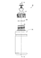
本実施形態では、タンク31へのインクの注入に、図2に示すボトル35が活用され得る。ボトル35には、タンク31へ注入するためのインクが収容されている。ボトル35は、分解図である図3に示すように、容器36と、キャップ37と、シール部材と38と、を有している。容器36は、インクを収容可能に構成されている。容器36とキャップ37とは、互いに別体で構成されている。容器36とキャップ37とは、図3中のA−A線における断面図である図4に示すように、それぞれに設けられたねじ部39によって、互いに係合可能に構成されている。
In the present embodiment, the
また、容器36とキャップ37とは、ねじ部39によって互いに着脱可能に構成されている。容器36に対してキャップ37を相対的に捻る(回す)ことによって、容器36からキャップ37を外すことができる。なお、以下において、容器36に設けられたねじ部39と、キャップ37に設けられたねじ部39とを互いに識別する場合に、容器36に設けられたねじ部39がねじ部39Aと表記され、キャップ37に設けられたねじ部39がねじ部39Bと表記される。
Further, the
インクは容器36内に収容されている。容器36は、弾性を有する材料で構成されており、図4に示すように、筒状の胴部41と、筒状の係合部42と、開口部43と、を有している。胴部41と係合部42とは、互いに一体に形成されている。胴部41は、係合部42のキャップ37側とは反対側に位置している。係合部42は、胴部41のキャップ37側に位置している。係合部42は、胴部41よりも細く形成されている。係合部42の外側の側部42Aにねじ部39Aが形成されている。ねじ部39Aは、側部42Aから突出して設けられている。開口部43は、係合部42の胴部41側とは反対側の端部43Aに形成されている。開口部43は、キャップ37側に向かって開口している。
The ink is contained in the
インクは、開口部43から胴部41内に注入されている。開口部43は、フィルム44によって容器36の外側から封止されている。フィルム44は、開口部43を覆う大きさ及び形状を有している。フィルム44は、開口部43の端部43Aに接合されている。フィルム44は、溶着により端部43Aに接合されている。これにより、容器36内の液密性が高く保たれ、インクが容器36に密封される。なお、容器36の材料としては、例えば、ポリエチレンテレフタレート(PET)、ナイロン、ポリエチレン、ポリプロピレン、ポリスチレンなどの樹脂が採用され得る。
Ink is injected into the
なお、利用者は、ボトル35からタンク31にインクを注入する際に、容器36からフィルム44を剥離してから注入を実施する。フィルム44の材料としては、例えば、ポリエチレンテレフタレート(PET)、ナイロン、ポリエチレンなどが採用され得る。また、これらの材料を積層した積層構造も採用され得る。さらに、これらの材料にアルミニウムなどを蒸着した層を有する構成も採用され得る。これにより、ガスバリア性を高めることができる。
When injecting ink from the
シール部材38は、フィルム44の容器36側とは反対側、すなわちフィルム44とキャップ37との間に位置している。キャップ37は、シール部材38の容器36側とは反対側に位置している。このため、フィルム44は、シール部材38と容器36とによって挟まれている。また、シール部材38は、フィルム44とキャップ37とによって挟まれている。そして、キャップ37は、フィルム44とシール部材38とを覆っている。上記の構成により、フィルム44は、シール部材38と容器36とによって挟持されている。また、シール部材38は、フィルム44とキャップ37とによって挟持されている。換言すれば、シール部材38とフィルム44とが、キャップ37と容器36とによって挟持されている。
The sealing
キャップ37は、図5に示すように、結合部51と、流出部52と、栓部53とに区分され得る。結合部51と流出部52と栓部53とは、相互に一体的に形成されている。結合部51は、筒状の外観を有している。結合部51の内側の側面には、ねじ部39Bが設けられている。結合部51は、ねじ部39Bによって容器36に係合される部位である。結合部51の内径は、容器36の係合部42(図4)の外径よりも広く構成されている。結合部51の内側にねじ部39Bが形成されており、容器36の係合部42の外側にねじ部39Aが形成されている。そして、結合部51の内側のねじ部39Bが係合部42の外側のねじ部39Aに係合することによって、キャップ37と容器36とが係合する。キャップ37と容器36とが係合した状態で、キャップ37の結合部51が、容器36の係合部42を覆う。
As shown in FIG. 5, the
流出部52は、シール部材38(図4)を挟んで容器36側とは反対側に突出している。栓部53は、流出部52の容器36側とは反対側に設けられている。流出部52は、管状を呈している。流出部52の内側には、導出流路54が形成されている。導出流路54は、平面視で開口部43の領域に重なる領域に設けられている。導出流路54は、流出部52において、平面視で開口部43の領域に重なる中空の領域である。
The
結合部51のうち流出部52との境界部55には、シール部材38に向かって突出する突出部56が設けられている。キャップ37を結合部51から流出部52に向かう方向に平面視したとき、突出部56は、環状に形成されており、導出流路54を囲んでいる。ボトル35において、容器36とキャップ37とが係合した状態で、突出部56がシール部材38を容器36側に向かって押圧している。本実施形態では、シール部材38が弾性及び柔軟性を有する部材で構成されているため、突出部56がシール部材38に食い込む。
A
図6に示すように、栓部53には、凹部57が形成されている。凹部57は、栓部53の流出部52側とは反対側から流出部52側に向かって凹となる向きに設けられている。なお、上述したように、流出部52と栓部53とが互いに一体的に形成されているので、導出流路54は、栓部53によって閉塞されている。栓部53は、利用者がインクをタンク31に注入するときに、図6に示すように、利用者によって流出部52から引き離される。例えば、利用者が栓部53をキャップ37から引きちぎることなどによって、栓部53を流出部52から引き離すことができる。
As shown in FIG. 6, a
栓部53が流出部52から引き離されると、流出部52の栓部53側が開口し、流出口58が形成される。これにより、導出流路54が容器36の外部と連通する。この結果、容器36内のインクは、開口部43から導出流路54を経て流出口58から容器36外に流出し得る。利用者がインクをタンク31に注入するとき、流出口58がタンク31のインク注入部33内に挿入される。そして、利用者は、容器36内のインクをインク注入部33からタンク31内に注入する。
When the
容器36内のインクをタンク31に注入しきれずに、インクが容器36内に余った場合などには、図7に示すように、栓部53で流出口58を塞ぐことができる。この場合、栓部53の凹部57を流出部52の流出口58側に向けて流出口58を凹部57内に嵌入することによって、流出口58が栓部53によって閉塞される。これにより、開封後の容器36内の気密性を高めることができる。
When the ink in the
シール部材38は、図8に示すように、開口部61が形成された環状の外観を有している。なお、図8は、シール部材38を容器36からキャップ37に向かう方向に平面視したときの図に相当する。シール部材38の周縁には、複数の切り欠き部62が形成されている。本実施形態では、複数の切り欠き部62は、それぞれ、三角状の外観を有している。複数の切り欠き部62は、シール部材38の周縁にわたって連続して形成されている。このため、シール部材38の外周は、複数の切り欠き部62によって囲まれているともみなされ得る。
As shown in FIG. 8, the
また、他の観点では、シール部材38の周縁には、複数の凸部63が形成されている。本実施形態では、複数の凸部63は、それぞれ、三角状の外観を有している。複数の凸部63は、シール部材38の周縁にわたって連続して形成されている。このため、シール部材38の外周は、複数の凸部63によって囲まれているともみなされ得る。
From another viewpoint, a plurality of
ここで、シール部材38の最外周の外径を、図5に示すように、D1とする。また、キャップ37において、ねじ部39Bのねじ山の頂部における内径をD2とする。本実施形態では、D1とD2とが、下記(1)式の関係を有している。
D1>D2…(1)
Here, the outer diameter of the outermost circumference of the
D1> D2 ... (1)
本実施形態では、シール部材38は、キャップ37の内側に係合可能に構成されている。シール部材38は、結合部51の内側に挿入される。シール部材38は、図9に示すように、キャップ37のねじ部39Bのうち最も流出部52側に位置するものと境界部55との間に配置される。上述したように、シール部材38の外径D1がねじ部39Bのねじ山の内径D2よりも大きい。つまり、シール部材38の最外縁が、キャップ37のねじ部39Bのねじ山の頂部よりも外側に位置する。このため、シール部材38を結合部51の内側に挿入するとき、シール部材38の最外縁がねじ部39Bのねじ山を乗り越える。そして、シール部材38が境界部55と最も流出部52側に位置するねじ部39Bとの間に配置されると、シール部材38の最外縁がねじ部39Bのねじ山に引っ掛かるので、シール部材38がキャップ37から脱落しにくくなる。
In the present embodiment, the
シール部材38がキャップ37の内側に係合した状態で、シール部材38の開口部61と導出流路54とが重なる。図4に示すフィルム44が容器36から剥離された状態でキャップ37が容器36に係合されると、シール部材38がキャップ37と容器36とによって挟持される。つまり、シール部材38は、キャップ37と容器36とによって挟持可能に構成されている。このとき、シール部材38の開口部61が導出流路54に重なるので、容器36内とキャップ37の導出流路54とがシール部材38の開口部61を介して連通する。このため、フィルム44が容器36から剥がされた状態において、容器36内のインクは、開口部43からシール部材38の開口部61を通って導出流路54内に流入することができる。
With the
このとき、シール部材38によって、容器36内のインクが容器36とキャップ37との間からしみ出すことを抑えることができる。これは、図10に示すように、容器36の係合部42の端部43Aとキャップ37との間にシール部材38が介在するので、容器36の端部43Aとキャップ37の境界部55との間の液密性が高められているためである。これにより、容器36の係合部42の端部43Aとシール部材38との間から容器36内のインクが係合部42の外側にしみ出すことを抑制することができる。また、キャップ37とシール部材38との間からインクが係合部42の外側にしみ出すことも抑制することができる。
At this time, the sealing
前述したように、シール部材38の周縁には、三角状の外観を有する複数の凸部63(図8)が形成されている。このため、例え、容器36の開口部43の端部43Aとシール部材38との間や、キャップ37とシール部材38との間からインクがしみ出たとしても、インクに含まれる界面活性剤によるぬれ性によって、しみ出たインクが三角状の外観を有する凸部63の先端に留まりやすい。このため、容器36内のインクが容器36とキャップ37との間からしみ出すことを抑制しやすい。
As described above, a plurality of convex portions 63 (FIG. 8) having a triangular appearance are formed on the peripheral edge of the
また、本実施形態では、前述したように、キャップ37と容器36とが係合した状態で、キャップ37の結合部51が、容器36の係合部42を覆う。このとき、図10に示すように、キャップ37は、シール部材38と容器36の係合部42とを覆う。これにより、本実施形態では、シール部材38による液密性の向上に加え、キャップ37が筒状の係合部42を覆うことによる液密性の向上も図られる。
Further, in the present embodiment, as described above, the connecting
また、本実施形態では、前述したように、キャップ37に突出部56が設けられている。ボトル35において、容器36とキャップ37とが係合した状態で、突出部56はシール部材38を容器36側に向かって押圧している。これにより、キャップ37とシール部材38との密着性を高めることができるため、ボトル35における液密性を一層高めることができる。
Further, in the present embodiment, as described above, the
また、本実施形態では、前述したように、容器36の開口部43がフィルム44(図4)によって封止されている。そして、ボトル35からタンク31にインクを注入する際に、フィルム44は利用者によって剥離される。つまり、ボトル35では、フィルム44が剥離可能に容器36に接合されている。フィルム44が容器36から剥離されたとき、フィルム44の剥離の際に剥離しきれなかった残りかすが開口部43の端部43Aに残っていると、端部43Aに凹凸が発生しやすい。開口部43の端部43Aに凹凸が発生すると、ボトル35の液密性が低下しやすい。しかし、本実施形態におけるボトル35では、開口部43の端部43Aとキャップ37との間に介在するシール部材38で凹凸を吸収しやすいので、ボトル35の液密性を高めることができる。
Further, in the present embodiment, as described above, the
また、本実施形態では、前述したように、シール部材38の外径D1がねじ部39Bのねじ山の内径D2よりも大きいため、シール部材38をキャップ37の内側に係合させたとき、シール部材38がキャップ37から脱落しにくい。これにより、キャップ37を容器36に係合させるときに、キャップ37と容器36とを容易に係合させることができる。
Further, in the present embodiment, as described above, since the outer diameter D1 of the
上記各実施形態において、インク噴射装置は、インク以外の他の液体を噴射したり吐出したり塗布したりして消費する液体噴射装置であってもよい。なお、液体噴射装置から微小量の液滴となって吐出される液体の状態としては、粒状、涙状、糸状に尾を引くものも含むものとする。また、ここでいう液体は、液体噴射装置で消費させることができるような材料であればよい。例えば、物質が液相であるときの状態のものであればよく、粘性の高い又は低い液状体、ゾル、ゲル水、その他の無機溶剤、有機溶剤、溶液、液状樹脂、液状金属(金属融液)のような流状体を含むものとする。また、物質の一状態としての液体のみならず、顔料や金属粒子などの固形物からなる機能材料の粒子が溶媒に溶解、分散又は混合されたものなども含むものとする。液体の代表的な例としては、上記各実施形態で説明したようなインクの他、液晶等も挙げられる。ここで、インクとは一般的な水性インク及び油性インク並びにジェルインク、ホットメルトインク等の各種液体組成物を包含するものとする。液体噴射装置の具体例としては、例えば、液晶ディスプレイ、EL(エレクトロルミネッセンス)ディスプレイ、面発光ディスプレイ、カラーフィルターの製造等に用いられる電極材や色材等の材料を分散又は溶解のかたちで含む液体を噴射する液体噴射装置がある。また、バイオチップ製造に用いられる生体有機物を噴射する液体噴射装置、精密ピペットとして用いられ試料となる液体を噴射する液体噴射装置、捺染装置やマイクロディスペンサー等であってもよい。さらに、時計やカメラ等の精密機械にピンポイントで潤滑油を噴射する液体噴射装置、光通信素子等に用いられる微小半球レンズ(光学レンズ)などを形成するために紫外線硬化樹脂等の透明樹脂液を基板上に噴射する液体噴射装置であってもよい。また、基板などをエッチングするために酸又はアルカリ等のエッチング液を噴射する液体噴射装置であってもよい。 In each of the above embodiments, the ink injection device may be a liquid injection device that injects, ejects, or applies a liquid other than ink to consume. It should be noted that the state of the liquid discharged as a minute amount of droplets from the liquid injection device includes those having a granular, tear-like, or thread-like tail. Further, the liquid referred to here may be any material that can be consumed by the liquid injection device. For example, the substance may be in a liquid phase, and may be a highly viscous or low-viscosity liquid, sol, gel water, other inorganic solvents, organic solvents, solutions, liquid resins, liquid metals (metal melts). ) Shall include a flowing body. Further, it includes not only a liquid as a state of a substance but also a particle of a functional material made of a solid substance such as a pigment or a metal particle dissolved, dispersed or mixed in a solvent. Typical examples of the liquid include liquid crystals and the like in addition to the inks described in the above embodiments. Here, the ink includes general water-based inks, oil-based inks, and various liquid compositions such as gel inks and hot melt inks. Specific examples of the liquid injection device include liquids containing materials such as electrode materials and color materials used in the manufacture of liquid crystal displays, EL (electroluminescence) displays, surface emitting displays, color filters, etc. in the form of dispersion or dissolution. There is a liquid injection device that injects. Further, it may be a liquid injection device for injecting a bioorganic substance used for producing a biochip, a liquid injection device for injecting a liquid as a sample used as a precision pipette, a printing device, a micro dispenser, or the like. Furthermore, a transparent resin liquid such as an ultraviolet curable resin is used to form a liquid injection device that injects lubricating oil pinpointly into precision machines such as watches and cameras, and a microhemispherical lens (optical lens) used for optical communication elements. May be a liquid injection device that injects light onto a substrate. Further, it may be a liquid injection device that injects an etching solution such as an acid or an alkali to etch a substrate or the like.
なお、本発明は、上述の実施形態や実施例に限られるものではなく、その趣旨を逸脱しない範囲において種々の構成で実現することができる。例えば、発明の概要の欄に記載した各形態中の技術的特徴に対応する実施形態、実施例中の技術的特徴は、上述の課題の一部又は全部を解決するために、あるいは、上述の効果の一部又は全部を達成するために、適宜、差し替えや、組み合わせを行うことが可能である。また、その技術的特徴が本明細書中に必須なものとして説明されていなければ、適宜、削除することが可能である。 The present invention is not limited to the above-described embodiments and examples, and can be realized with various configurations without departing from the spirit of the present invention. For example, the embodiment corresponding to the technical feature in each embodiment described in the column of the outline of the invention, the technical feature in the embodiment may be used to solve a part or all of the above-mentioned problems, or the above-mentioned. It is possible to replace or combine them as appropriate to achieve some or all of the effects. Further, if the technical feature is not described as essential in the present specification, it can be appropriately deleted.
1…インク噴射システム、3…プリンター、4…インク供給装置、6…記録部、9…制御部、11…筐体、17…キャリッジ、19…記録ヘッド、31…タンク、32…筐体、33…インク注入部、34…インク供給チューブ、35…ボトル、36…容器、37…キャップ、38…シール部材、39…ねじ部、39A,39B…ねじ部、41…胴部、42…係合部、42A…側部、43…開口部、43A…端部、44…フィルム、51…結合部、52…流出部、53…栓部、54…導出流路、55…境界部、56…突出部、57…凹部、58…流出口、61…開口部、62…切り欠き部、63…凸部、P…記録媒体。 1 ... Ink injection system, 3 ... Printer, 4 ... Ink supply device, 6 ... Recording unit, 9 ... Control unit, 11 ... Housing, 17 ... Carriage, 19 ... Recording head, 31 ... Tank, 32 ... Housing, 33 ... Ink injection part, 34 ... Ink supply tube, 35 ... Bottle, 36 ... Container, 37 ... Cap, 38 ... Seal member, 39 ... Screw part, 39A, 39B ... Screw part, 41 ... Body part, 42 ... Engagement part , 42A ... Side, 43 ... Opening, 43A ... End, 44 ... Film, 51 ... Coupling, 52 ... Outflow, 53 ... Plug, 54 ... Derived flow path, 55 ... Boundary, 56 ... Protruding , 57 ... concave, 58 ... outlet, 61 ... opening, 62 ... notch, 63 ... convex, P ... recording medium.
Claims (2)
前記容器の前記第1ねじ部に係合可能な第2ねじ部が内側に形成された結合部と、前記結合部より内径の小さい流出口を有する流出部と、前記結合部と前記流出部とをつなぐ境界部と、を有するキャップと、
前記キャップが前記容器の前記係合部と係合した状態で、前記境界部と前記端部との間に挟まれる環状のシール部材と、
を備え、
前記シール部材は、該シール部材の外周に、三角状凸部が連続的に形成されている、
ことを特徴とするボトル。 It has a body portion capable of accommodating ink inside and an engaging portion formed integrally with the body portion, and the engaging portion has an opening formed at an end opposite to the body portion. And a container with a first threaded portion formed on the side ,
A joint portion in which a second threaded portion that can be engaged with the first screw portion of the container is formed inside, an outflow portion having an outlet having an inner diameter smaller than that of the joint portion, and the joint portion and the outflow portion. With a cap that has a boundary that connects the
An annular sealing member sandwiched between the boundary portion and the end portion in a state where the cap is engaged with the engaging portion of the container.
With
The seal member has a triangular convex portion continuously formed on the outer periphery of the seal member.
A bottle that features that.
前記キャップは、前記容器と係合した状態で、前記境界部の、前記係合部の前記端部と対向する領域から、前記開口部の中心軸に沿う方向に突出する環状の突出部を備え、
前記シール部材は、前記キャップが前記容器と係合した状態で、前記突出部により前記容器側に向けて押圧される、
ことを特徴とするボトル。 The bottle according to claim 1.
The cap includes an annular protrusion that projects in a direction along the central axis of the opening from a region of the boundary that faces the end of the engagement while engaged with the container. ,
The seal member is pressed toward the container by the protrusion while the cap is engaged with the container.
A bottle that features that.
Priority Applications (1)
| Application Number | Priority Date | Filing Date | Title |
|---|---|---|---|
| JP2015206149A JP6794620B2 (en) | 2015-10-20 | 2015-10-20 | Bottle |
Applications Claiming Priority (1)
| Application Number | Priority Date | Filing Date | Title |
|---|---|---|---|
| JP2015206149A JP6794620B2 (en) | 2015-10-20 | 2015-10-20 | Bottle |
Publications (3)
| Publication Number | Publication Date |
|---|---|
| JP2017077901A JP2017077901A (en) | 2017-04-27 |
| JP2017077901A5 JP2017077901A5 (en) | 2018-11-22 |
| JP6794620B2 true JP6794620B2 (en) | 2020-12-02 |
Family
ID=58665159
Family Applications (1)
| Application Number | Title | Priority Date | Filing Date |
|---|---|---|---|
| JP2015206149A Active JP6794620B2 (en) | 2015-10-20 | 2015-10-20 | Bottle |
Country Status (1)
| Country | Link |
|---|---|
| JP (1) | JP6794620B2 (en) |
Families Citing this family (2)
| Publication number | Priority date | Publication date | Assignee | Title |
|---|---|---|---|---|
| JP2020083355A (en) * | 2018-11-20 | 2020-06-04 | 大商硝子株式会社 | container |
| JP7404826B2 (en) * | 2019-11-29 | 2023-12-26 | セイコーエプソン株式会社 | Ink supply container set, ink supply container, and its packaging |
Family Cites Families (4)
| Publication number | Priority date | Publication date | Assignee | Title |
|---|---|---|---|---|
| JPS57123761U (en) * | 1981-12-14 | 1982-08-02 | ||
| JPS633967U (en) * | 1986-06-27 | 1988-01-12 | ||
| JPH0283256U (en) * | 1988-12-16 | 1990-06-27 | ||
| JP6171309B2 (en) * | 2012-10-31 | 2017-08-02 | セイコーエプソン株式会社 | Bottle set |
-
2015
- 2015-10-20 JP JP2015206149A patent/JP6794620B2/en active Active
Also Published As
| Publication number | Publication date |
|---|---|
| JP2017077901A (en) | 2017-04-27 |
Similar Documents
| Publication | Publication Date | Title |
|---|---|---|
| JP6907559B2 (en) | Ink bottle | |
| JP6724564B2 (en) | Bottle set | |
| WO2014112344A1 (en) | Liquid jetting device and tank | |
| JP5896070B2 (en) | Liquid ejector | |
| US11691428B2 (en) | Bottle set and bottle | |
| JP6307887B2 (en) | Liquid container and printer | |
| JP6171309B2 (en) | Bottle set | |
| JP6953906B2 (en) | Ink replenishment container | |
| JP2016221798A (en) | Liquid container, liquid supply device and liquid jet system | |
| JP2015174271A (en) | liquid tank and printer | |
| JP6809121B2 (en) | Bottle set | |
| JP6794620B2 (en) | Bottle | |
| JP6372085B2 (en) | Liquid ejector | |
| JP6992339B2 (en) | Ink replenishment container, how to regenerate the ink replenishment container | |
| JP2017140794A (en) | Liquid storage body and liquid jet device | |
| JP6880588B2 (en) | Bottle set | |
| US20190127135A1 (en) | Liquid container | |
| JP6163966B2 (en) | Liquid container and its lid |
Legal Events
| Date | Code | Title | Description |
|---|---|---|---|
| RD05 | Notification of revocation of power of attorney |
Free format text: JAPANESE INTERMEDIATE CODE: A7425 Effective date: 20180906 |
|
| A521 | Written amendment |
Free format text: JAPANESE INTERMEDIATE CODE: A523 Effective date: 20181008 |
|
| A621 | Written request for application examination |
Free format text: JAPANESE INTERMEDIATE CODE: A621 Effective date: 20181008 |
|
| RD03 | Notification of appointment of power of attorney |
Free format text: JAPANESE INTERMEDIATE CODE: A7423 Effective date: 20181119 |
|
| A977 | Report on retrieval |
Free format text: JAPANESE INTERMEDIATE CODE: A971007 Effective date: 20190725 |
|
| A131 | Notification of reasons for refusal |
Free format text: JAPANESE INTERMEDIATE CODE: A131 Effective date: 20190903 |
|
| A521 | Written amendment |
Free format text: JAPANESE INTERMEDIATE CODE: A523 Effective date: 20191031 |
|
| A131 | Notification of reasons for refusal |
Free format text: JAPANESE INTERMEDIATE CODE: A131 Effective date: 20200331 |
|
| A521 | Written amendment |
Free format text: JAPANESE INTERMEDIATE CODE: A523 Effective date: 20200522 |
|
| RD07 | Notification of extinguishment of power of attorney |
Free format text: JAPANESE INTERMEDIATE CODE: A7427 Effective date: 20200803 |
|
| TRDD | Decision of grant or rejection written | ||
| A01 | Written decision to grant a patent or to grant a registration (utility model) |
Free format text: JAPANESE INTERMEDIATE CODE: A01 Effective date: 20201013 |
|
| A61 | First payment of annual fees (during grant procedure) |
Free format text: JAPANESE INTERMEDIATE CODE: A61 Effective date: 20201026 |
|
| R150 | Certificate of patent or registration of utility model |
Ref document number: 6794620 Country of ref document: JP Free format text: JAPANESE INTERMEDIATE CODE: R150 |