JP7102402B2 - Plate-like composite material containing polytetrafluoroethylene and filler - Google Patents
Plate-like composite material containing polytetrafluoroethylene and filler Download PDFInfo
- Publication number
- JP7102402B2 JP7102402B2 JP2019521255A JP2019521255A JP7102402B2 JP 7102402 B2 JP7102402 B2 JP 7102402B2 JP 2019521255 A JP2019521255 A JP 2019521255A JP 2019521255 A JP2019521255 A JP 2019521255A JP 7102402 B2 JP7102402 B2 JP 7102402B2
- Authority
- JP
- Japan
- Prior art keywords
- composite material
- filler
- less
- mass
- inorganic fine
- Prior art date
- Legal status (The legal status is an assumption and is not a legal conclusion. Google has not performed a legal analysis and makes no representation as to the accuracy of the status listed.)
- Active
Links
- 239000002131 composite material Substances 0.000 title claims description 126
- 239000000945 filler Substances 0.000 title claims description 68
- 229920001343 polytetrafluoroethylene Polymers 0.000 title claims description 46
- 239000004810 polytetrafluoroethylene Substances 0.000 title claims description 46
- -1 polytetrafluoroethylene Polymers 0.000 title claims description 43
- 239000010419 fine particle Substances 0.000 claims description 86
- 238000012360 testing method Methods 0.000 claims description 44
- 239000007788 liquid Substances 0.000 claims description 36
- 239000000203 mixture Substances 0.000 claims description 24
- 238000009736 wetting Methods 0.000 claims description 23
- 230000002940 repellent Effects 0.000 claims description 21
- 239000005871 repellent Substances 0.000 claims description 21
- 230000005484 gravity Effects 0.000 claims description 18
- 239000011259 mixed solution Substances 0.000 claims description 16
- 239000011164 primary particle Substances 0.000 claims description 16
- 230000004931 aggregating effect Effects 0.000 claims description 5
- 238000000034 method Methods 0.000 description 48
- VYPSYNLAJGMNEJ-UHFFFAOYSA-N Silicium dioxide Chemical compound O=[Si]=O VYPSYNLAJGMNEJ-UHFFFAOYSA-N 0.000 description 45
- 238000005096 rolling process Methods 0.000 description 36
- OKKJLVBELUTLKV-UHFFFAOYSA-N Methanol Chemical compound OC OKKJLVBELUTLKV-UHFFFAOYSA-N 0.000 description 33
- 239000003607 modifier Substances 0.000 description 29
- 239000000047 product Substances 0.000 description 26
- 239000010410 layer Substances 0.000 description 25
- 239000002245 particle Substances 0.000 description 19
- 239000000654 additive Substances 0.000 description 17
- 238000010438 heat treatment Methods 0.000 description 16
- 230000000996 additive effect Effects 0.000 description 15
- 239000000463 material Substances 0.000 description 15
- 229910002012 Aerosil® Inorganic materials 0.000 description 14
- 238000004519 manufacturing process Methods 0.000 description 14
- 229910052751 metal Inorganic materials 0.000 description 14
- 239000002184 metal Substances 0.000 description 14
- 239000000758 substrate Substances 0.000 description 14
- 230000008859 change Effects 0.000 description 13
- 239000000243 solution Substances 0.000 description 13
- 238000009835 boiling Methods 0.000 description 12
- SNRUBQQJIBEYMU-UHFFFAOYSA-N dodecane Chemical compound CCCCCCCCCCCC SNRUBQQJIBEYMU-UHFFFAOYSA-N 0.000 description 12
- 239000000843 powder Substances 0.000 description 12
- 239000000377 silicon dioxide Substances 0.000 description 12
- 238000011282 treatment Methods 0.000 description 12
- 230000002209 hydrophobic effect Effects 0.000 description 11
- 238000002156 mixing Methods 0.000 description 11
- GWEVSGVZZGPLCZ-UHFFFAOYSA-N Titan oxide Chemical compound O=[Ti]=O GWEVSGVZZGPLCZ-UHFFFAOYSA-N 0.000 description 10
- 238000000465 moulding Methods 0.000 description 10
- 229920005989 resin Polymers 0.000 description 9
- 239000011347 resin Substances 0.000 description 9
- 230000000052 comparative effect Effects 0.000 description 8
- 238000002844 melting Methods 0.000 description 8
- 230000008018 melting Effects 0.000 description 8
- 239000012466 permeate Substances 0.000 description 8
- 150000001875 compounds Chemical class 0.000 description 7
- 229910021485 fumed silica Inorganic materials 0.000 description 7
- 238000000059 patterning Methods 0.000 description 7
- 239000011148 porous material Substances 0.000 description 7
- XLYOFNOQVPJJNP-UHFFFAOYSA-N water Substances O XLYOFNOQVPJJNP-UHFFFAOYSA-N 0.000 description 7
- MCMNRKCIXSYSNV-UHFFFAOYSA-N Zirconium dioxide Chemical compound O=[Zr]=O MCMNRKCIXSYSNV-UHFFFAOYSA-N 0.000 description 6
- 229920000642 polymer Polymers 0.000 description 6
- 238000002360 preparation method Methods 0.000 description 6
- AVYKQOAMZCAHRG-UHFFFAOYSA-N triethoxy(3,3,4,4,5,5,6,6,7,7,8,8,8-tridecafluorooctyl)silane Chemical compound CCO[Si](OCC)(OCC)CCC(F)(F)C(F)(F)C(F)(F)C(F)(F)C(F)(F)C(F)(F)F AVYKQOAMZCAHRG-UHFFFAOYSA-N 0.000 description 6
- 238000011049 filling Methods 0.000 description 5
- 125000001153 fluoro group Chemical group F* 0.000 description 5
- 125000000524 functional group Chemical group 0.000 description 5
- 238000007654 immersion Methods 0.000 description 5
- 239000002243 precursor Substances 0.000 description 5
- 235000012239 silicon dioxide Nutrition 0.000 description 5
- UQSXHKLRYXJYBZ-UHFFFAOYSA-N Iron oxide Chemical compound [Fe]=O UQSXHKLRYXJYBZ-UHFFFAOYSA-N 0.000 description 4
- KFZMGEQAYNKOFK-UHFFFAOYSA-N Isopropanol Chemical compound CC(C)O KFZMGEQAYNKOFK-UHFFFAOYSA-N 0.000 description 4
- 239000007864 aqueous solution Substances 0.000 description 4
- FFUAGWLWBBFQJT-UHFFFAOYSA-N hexamethyldisilazane Chemical compound C[Si](C)(C)N[Si](C)(C)C FFUAGWLWBBFQJT-UHFFFAOYSA-N 0.000 description 4
- 238000010030 laminating Methods 0.000 description 4
- 239000000126 substance Substances 0.000 description 4
- QTBSBXVTEAMEQO-UHFFFAOYSA-N Acetic acid Chemical compound CC(O)=O QTBSBXVTEAMEQO-UHFFFAOYSA-N 0.000 description 3
- 229910052582 BN Inorganic materials 0.000 description 3
- PZNSFCLAULLKQX-UHFFFAOYSA-N Boron nitride Chemical compound N#B PZNSFCLAULLKQX-UHFFFAOYSA-N 0.000 description 3
- LFQSCWFLJHTTHZ-UHFFFAOYSA-N Ethanol Chemical compound CCO LFQSCWFLJHTTHZ-UHFFFAOYSA-N 0.000 description 3
- 239000004813 Perfluoroalkoxy alkane Substances 0.000 description 3
- 206010061592 cardiac fibrillation Diseases 0.000 description 3
- 230000002600 fibrillogenic effect Effects 0.000 description 3
- 125000001165 hydrophobic group Chemical group 0.000 description 3
- 238000005259 measurement Methods 0.000 description 3
- 238000012986 modification Methods 0.000 description 3
- 230000004048 modification Effects 0.000 description 3
- VLKZOEOYAKHREP-UHFFFAOYSA-N n-Hexane Chemical compound CCCCCC VLKZOEOYAKHREP-UHFFFAOYSA-N 0.000 description 3
- 229920011301 perfluoro alkoxyl alkane Polymers 0.000 description 3
- 230000000704 physical effect Effects 0.000 description 3
- BASFCYQUMIYNBI-UHFFFAOYSA-N platinum Chemical compound [Pt] BASFCYQUMIYNBI-UHFFFAOYSA-N 0.000 description 3
- 230000008569 process Effects 0.000 description 3
- 239000007787 solid Substances 0.000 description 3
- 239000002904 solvent Substances 0.000 description 3
- 238000001179 sorption measurement Methods 0.000 description 3
- IJGRMHOSHXDMSA-UHFFFAOYSA-N Atomic nitrogen Chemical compound N#N IJGRMHOSHXDMSA-UHFFFAOYSA-N 0.000 description 2
- 238000012935 Averaging Methods 0.000 description 2
- LRHPLDYGYMQRHN-UHFFFAOYSA-N N-Butanol Chemical compound CCCCO LRHPLDYGYMQRHN-UHFFFAOYSA-N 0.000 description 2
- IMNFDUFMRHMDMM-UHFFFAOYSA-N N-Heptane Chemical compound CCCCCCC IMNFDUFMRHMDMM-UHFFFAOYSA-N 0.000 description 2
- 239000002033 PVDF binder Substances 0.000 description 2
- 229910052581 Si3N4 Inorganic materials 0.000 description 2
- 239000012790 adhesive layer Substances 0.000 description 2
- 150000001298 alcohols Chemical class 0.000 description 2
- 239000010949 copper Substances 0.000 description 2
- 239000004205 dimethyl polysiloxane Substances 0.000 description 2
- 235000013870 dimethyl polysiloxane Nutrition 0.000 description 2
- 239000006185 dispersion Substances 0.000 description 2
- 238000005516 engineering process Methods 0.000 description 2
- 238000001125 extrusion Methods 0.000 description 2
- 239000012765 fibrous filler Substances 0.000 description 2
- 229920002313 fluoropolymer Polymers 0.000 description 2
- 239000004811 fluoropolymer Substances 0.000 description 2
- 239000011888 foil Substances 0.000 description 2
- 239000007789 gas Substances 0.000 description 2
- 239000010931 gold Substances 0.000 description 2
- 150000002430 hydrocarbons Chemical group 0.000 description 2
- 239000011159 matrix material Substances 0.000 description 2
- 150000004767 nitrides Chemical class 0.000 description 2
- BKIMMITUMNQMOS-UHFFFAOYSA-N nonane Chemical compound CCCCCCCCC BKIMMITUMNQMOS-UHFFFAOYSA-N 0.000 description 2
- 239000003921 oil Substances 0.000 description 2
- RVTZCBVAJQQJTK-UHFFFAOYSA-N oxygen(2-);zirconium(4+) Chemical compound [O-2].[O-2].[Zr+4] RVTZCBVAJQQJTK-UHFFFAOYSA-N 0.000 description 2
- 229920000435 poly(dimethylsiloxane) Polymers 0.000 description 2
- 229920002981 polyvinylidene fluoride Polymers 0.000 description 2
- 238000012545 processing Methods 0.000 description 2
- FZHAPNGMFPVSLP-UHFFFAOYSA-N silanamine Chemical compound [SiH3]N FZHAPNGMFPVSLP-UHFFFAOYSA-N 0.000 description 2
- LIVNPJMFVYWSIS-UHFFFAOYSA-N silicon monoxide Chemical compound [Si-]#[O+] LIVNPJMFVYWSIS-UHFFFAOYSA-N 0.000 description 2
- HQVNEWCFYHHQES-UHFFFAOYSA-N silicon nitride Chemical compound N12[Si]34N5[Si]62N3[Si]51N64 HQVNEWCFYHHQES-UHFFFAOYSA-N 0.000 description 2
- 229920002545 silicone oil Polymers 0.000 description 2
- 150000003384 small molecules Chemical class 0.000 description 2
- 238000005507 spraying Methods 0.000 description 2
- BGHCVCJVXZWKCC-UHFFFAOYSA-N tetradecane Chemical compound CCCCCCCCCCCCCC BGHCVCJVXZWKCC-UHFFFAOYSA-N 0.000 description 2
- BFKJFAAPBSQJPD-UHFFFAOYSA-N tetrafluoroethene Chemical group FC(F)=C(F)F BFKJFAAPBSQJPD-UHFFFAOYSA-N 0.000 description 2
- 238000005979 thermal decomposition reaction Methods 0.000 description 2
- 239000004408 titanium dioxide Substances 0.000 description 2
- OGIDPMRJRNCKJF-UHFFFAOYSA-N titanium oxide Inorganic materials [Ti]=O OGIDPMRJRNCKJF-UHFFFAOYSA-N 0.000 description 2
- 229910000314 transition metal oxide Inorganic materials 0.000 description 2
- IIYFAKIEWZDVMP-UHFFFAOYSA-N tridecane Chemical compound CCCCCCCCCCCCC IIYFAKIEWZDVMP-UHFFFAOYSA-N 0.000 description 2
- RSJKGSCJYJTIGS-UHFFFAOYSA-N undecane Chemical compound CCCCCCCCCCC RSJKGSCJYJTIGS-UHFFFAOYSA-N 0.000 description 2
- 229910001928 zirconium oxide Inorganic materials 0.000 description 2
- OKTJSMMVPCPJKN-UHFFFAOYSA-N Carbon Chemical compound [C] OKTJSMMVPCPJKN-UHFFFAOYSA-N 0.000 description 1
- 229920000049 Carbon (fiber) Polymers 0.000 description 1
- RYGMFSIKBFXOCR-UHFFFAOYSA-N Copper Chemical compound [Cu] RYGMFSIKBFXOCR-UHFFFAOYSA-N 0.000 description 1
- 229920001780 ECTFE Polymers 0.000 description 1
- VGGSQFUCUMXWEO-UHFFFAOYSA-N Ethene Chemical compound C=C VGGSQFUCUMXWEO-UHFFFAOYSA-N 0.000 description 1
- 239000005977 Ethylene Substances 0.000 description 1
- 239000004698 Polyethylene Substances 0.000 description 1
- 229920006361 Polyflon Polymers 0.000 description 1
- 239000004743 Polypropylene Substances 0.000 description 1
- 239000004793 Polystyrene Substances 0.000 description 1
- BQCADISMDOOEFD-UHFFFAOYSA-N Silver Chemical compound [Ag] BQCADISMDOOEFD-UHFFFAOYSA-N 0.000 description 1
- 235000010724 Wisteria floribunda Nutrition 0.000 description 1
- 230000002776 aggregation Effects 0.000 description 1
- 238000004220 aggregation Methods 0.000 description 1
- 150000001335 aliphatic alkanes Chemical class 0.000 description 1
- 125000001931 aliphatic group Chemical group 0.000 description 1
- 125000005370 alkoxysilyl group Chemical group 0.000 description 1
- 239000000956 alloy Substances 0.000 description 1
- 229910045601 alloy Inorganic materials 0.000 description 1
- 229910052782 aluminium Inorganic materials 0.000 description 1
- XAGFODPZIPBFFR-UHFFFAOYSA-N aluminium Chemical compound [Al] XAGFODPZIPBFFR-UHFFFAOYSA-N 0.000 description 1
- PNEYBMLMFCGWSK-UHFFFAOYSA-N aluminium oxide Inorganic materials [O-2].[O-2].[O-2].[Al+3].[Al+3] PNEYBMLMFCGWSK-UHFFFAOYSA-N 0.000 description 1
- 238000004458 analytical method Methods 0.000 description 1
- 229910052799 carbon Inorganic materials 0.000 description 1
- 125000004432 carbon atom Chemical group C* 0.000 description 1
- 239000006229 carbon black Substances 0.000 description 1
- 239000004917 carbon fiber Substances 0.000 description 1
- 230000015271 coagulation Effects 0.000 description 1
- 238000005345 coagulation Methods 0.000 description 1
- 239000003086 colorant Substances 0.000 description 1
- 239000000470 constituent Substances 0.000 description 1
- 229920001577 copolymer Polymers 0.000 description 1
- 229910052802 copper Inorganic materials 0.000 description 1
- DIOQZVSQGTUSAI-NJFSPNSNSA-N decane Chemical compound CCCCCCCCC[14CH3] DIOQZVSQGTUSAI-NJFSPNSNSA-N 0.000 description 1
- 238000000354 decomposition reaction Methods 0.000 description 1
- 230000007547 defect Effects 0.000 description 1
- 238000011161 development Methods 0.000 description 1
- 239000012153 distilled water Substances 0.000 description 1
- 238000005553 drilling Methods 0.000 description 1
- 238000001035 drying Methods 0.000 description 1
- 238000009713 electroplating Methods 0.000 description 1
- 150000002148 esters Chemical class 0.000 description 1
- 238000005530 etching Methods 0.000 description 1
- 150000002170 ethers Chemical class 0.000 description 1
- 229920001038 ethylene copolymer Polymers 0.000 description 1
- 229920000840 ethylene tetrafluoroethylene copolymer Polymers 0.000 description 1
- 239000000835 fiber Substances 0.000 description 1
- 238000007667 floating Methods 0.000 description 1
- 239000005350 fused silica glass Substances 0.000 description 1
- 239000011521 glass Substances 0.000 description 1
- 239000003365 glass fiber Substances 0.000 description 1
- PCHJSUWPFVWCPO-UHFFFAOYSA-N gold Chemical compound [Au] PCHJSUWPFVWCPO-UHFFFAOYSA-N 0.000 description 1
- 229910052737 gold Inorganic materials 0.000 description 1
- 229930195733 hydrocarbon Natural products 0.000 description 1
- 229910002011 hydrophilic fumed silica Inorganic materials 0.000 description 1
- 125000002887 hydroxy group Chemical group [H]O* 0.000 description 1
- VNWKTOKETHGBQD-UHFFFAOYSA-N methane Chemical compound C VNWKTOKETHGBQD-UHFFFAOYSA-N 0.000 description 1
- 239000004005 microsphere Substances 0.000 description 1
- 238000010295 mobile communication Methods 0.000 description 1
- 238000002715 modification method Methods 0.000 description 1
- DIOQZVSQGTUSAI-UHFFFAOYSA-N n-butylhexane Natural products CCCCCCCCCC DIOQZVSQGTUSAI-UHFFFAOYSA-N 0.000 description 1
- 229910052757 nitrogen Inorganic materials 0.000 description 1
- TVMXDCGIABBOFY-UHFFFAOYSA-N octane Chemical compound CCCCCCCC TVMXDCGIABBOFY-UHFFFAOYSA-N 0.000 description 1
- 239000005416 organic matter Substances 0.000 description 1
- 230000008520 organization Effects 0.000 description 1
- TWNQGVIAIRXVLR-UHFFFAOYSA-N oxo(oxoalumanyloxy)alumane Chemical compound O=[Al]O[Al]=O TWNQGVIAIRXVLR-UHFFFAOYSA-N 0.000 description 1
- 230000035515 penetration Effects 0.000 description 1
- 229920002120 photoresistant polymer Polymers 0.000 description 1
- 238000007747 plating Methods 0.000 description 1
- 229910052697 platinum Inorganic materials 0.000 description 1
- 229920002493 poly(chlorotrifluoroethylene) Polymers 0.000 description 1
- 239000005023 polychlorotrifluoroethylene (PCTFE) polymer Substances 0.000 description 1
- 229920000573 polyethylene Polymers 0.000 description 1
- 229920001155 polypropylene Polymers 0.000 description 1
- 229920002223 polystyrene Polymers 0.000 description 1
- 230000009257 reactivity Effects 0.000 description 1
- 229930195734 saturated hydrocarbon Natural products 0.000 description 1
- 238000010008 shearing Methods 0.000 description 1
- 229910002027 silica gel Inorganic materials 0.000 description 1
- 239000000741 silica gel Substances 0.000 description 1
- 229910052814 silicon oxide Inorganic materials 0.000 description 1
- 229910052709 silver Inorganic materials 0.000 description 1
- 239000004332 silver Substances 0.000 description 1
- 238000004544 sputter deposition Methods 0.000 description 1
- 238000003756 stirring Methods 0.000 description 1
- 239000004094 surface-active agent Substances 0.000 description 1
- 239000012085 test solution Substances 0.000 description 1
- 238000002411 thermogravimetry Methods 0.000 description 1
- 230000000930 thermomechanical effect Effects 0.000 description 1
- 229920005992 thermoplastic resin Polymers 0.000 description 1
- 239000011800 void material Substances 0.000 description 1
Images


Classifications
-
- C—CHEMISTRY; METALLURGY
- C08—ORGANIC MACROMOLECULAR COMPOUNDS; THEIR PREPARATION OR CHEMICAL WORKING-UP; COMPOSITIONS BASED THEREON
- C08K—Use of inorganic or non-macromolecular organic substances as compounding ingredients
- C08K7/00—Use of ingredients characterised by shape
- C08K7/22—Expanded, porous or hollow particles
- C08K7/24—Expanded, porous or hollow particles inorganic
- C08K7/26—Silicon- containing compounds
-
- H—ELECTRICITY
- H05—ELECTRIC TECHNIQUES NOT OTHERWISE PROVIDED FOR
- H05K—PRINTED CIRCUITS; CASINGS OR CONSTRUCTIONAL DETAILS OF ELECTRIC APPARATUS; MANUFACTURE OF ASSEMBLAGES OF ELECTRICAL COMPONENTS
- H05K1/00—Printed circuits
- H05K1/02—Details
- H05K1/03—Use of materials for the substrate
- H05K1/0313—Organic insulating material
- H05K1/0353—Organic insulating material consisting of two or more materials, e.g. two or more polymers, polymer + filler, + reinforcement
- H05K1/0373—Organic insulating material consisting of two or more materials, e.g. two or more polymers, polymer + filler, + reinforcement containing additives, e.g. fillers
-
- C—CHEMISTRY; METALLURGY
- C08—ORGANIC MACROMOLECULAR COMPOUNDS; THEIR PREPARATION OR CHEMICAL WORKING-UP; COMPOSITIONS BASED THEREON
- C08K—Use of inorganic or non-macromolecular organic substances as compounding ingredients
- C08K7/00—Use of ingredients characterised by shape
- C08K7/22—Expanded, porous or hollow particles
- C08K7/24—Expanded, porous or hollow particles inorganic
-
- C—CHEMISTRY; METALLURGY
- C08—ORGANIC MACROMOLECULAR COMPOUNDS; THEIR PREPARATION OR CHEMICAL WORKING-UP; COMPOSITIONS BASED THEREON
- C08K—Use of inorganic or non-macromolecular organic substances as compounding ingredients
- C08K3/00—Use of inorganic substances as compounding ingredients
- C08K3/34—Silicon-containing compounds
- C08K3/36—Silica
-
- C—CHEMISTRY; METALLURGY
- C08—ORGANIC MACROMOLECULAR COMPOUNDS; THEIR PREPARATION OR CHEMICAL WORKING-UP; COMPOSITIONS BASED THEREON
- C08K—Use of inorganic or non-macromolecular organic substances as compounding ingredients
- C08K9/00—Use of pretreated ingredients
- C08K9/04—Ingredients treated with organic substances
- C08K9/06—Ingredients treated with organic substances with silicon-containing compounds
-
- C—CHEMISTRY; METALLURGY
- C08—ORGANIC MACROMOLECULAR COMPOUNDS; THEIR PREPARATION OR CHEMICAL WORKING-UP; COMPOSITIONS BASED THEREON
- C08L—COMPOSITIONS OF MACROMOLECULAR COMPOUNDS
- C08L27/00—Compositions of homopolymers or copolymers of compounds having one or more unsaturated aliphatic radicals, each having only one carbon-to-carbon double bond, and at least one being terminated by a halogen; Compositions of derivatives of such polymers
- C08L27/02—Compositions of homopolymers or copolymers of compounds having one or more unsaturated aliphatic radicals, each having only one carbon-to-carbon double bond, and at least one being terminated by a halogen; Compositions of derivatives of such polymers not modified by chemical after-treatment
- C08L27/12—Compositions of homopolymers or copolymers of compounds having one or more unsaturated aliphatic radicals, each having only one carbon-to-carbon double bond, and at least one being terminated by a halogen; Compositions of derivatives of such polymers not modified by chemical after-treatment containing fluorine atoms
- C08L27/18—Homopolymers or copolymers or tetrafluoroethene
-
- H—ELECTRICITY
- H05—ELECTRIC TECHNIQUES NOT OTHERWISE PROVIDED FOR
- H05K—PRINTED CIRCUITS; CASINGS OR CONSTRUCTIONAL DETAILS OF ELECTRIC APPARATUS; MANUFACTURE OF ASSEMBLAGES OF ELECTRICAL COMPONENTS
- H05K1/00—Printed circuits
- H05K1/02—Details
- H05K1/03—Use of materials for the substrate
-
- C—CHEMISTRY; METALLURGY
- C08—ORGANIC MACROMOLECULAR COMPOUNDS; THEIR PREPARATION OR CHEMICAL WORKING-UP; COMPOSITIONS BASED THEREON
- C08K—Use of inorganic or non-macromolecular organic substances as compounding ingredients
- C08K2201/00—Specific properties of additives
- C08K2201/002—Physical properties
- C08K2201/003—Additives being defined by their diameter
-
- C—CHEMISTRY; METALLURGY
- C08—ORGANIC MACROMOLECULAR COMPOUNDS; THEIR PREPARATION OR CHEMICAL WORKING-UP; COMPOSITIONS BASED THEREON
- C08K—Use of inorganic or non-macromolecular organic substances as compounding ingredients
- C08K2201/00—Specific properties of additives
- C08K2201/002—Physical properties
- C08K2201/006—Additives being defined by their surface area
-
- C—CHEMISTRY; METALLURGY
- C08—ORGANIC MACROMOLECULAR COMPOUNDS; THEIR PREPARATION OR CHEMICAL WORKING-UP; COMPOSITIONS BASED THEREON
- C08K—Use of inorganic or non-macromolecular organic substances as compounding ingredients
- C08K2201/00—Specific properties of additives
- C08K2201/011—Nanostructured additives
-
- H—ELECTRICITY
- H05—ELECTRIC TECHNIQUES NOT OTHERWISE PROVIDED FOR
- H05K—PRINTED CIRCUITS; CASINGS OR CONSTRUCTIONAL DETAILS OF ELECTRIC APPARATUS; MANUFACTURE OF ASSEMBLAGES OF ELECTRICAL COMPONENTS
- H05K2201/00—Indexing scheme relating to printed circuits covered by H05K1/00
- H05K2201/01—Dielectrics
- H05K2201/0137—Materials
- H05K2201/015—Fluoropolymer, e.g. polytetrafluoroethylene [PTFE]
-
- H—ELECTRICITY
- H05—ELECTRIC TECHNIQUES NOT OTHERWISE PROVIDED FOR
- H05K—PRINTED CIRCUITS; CASINGS OR CONSTRUCTIONAL DETAILS OF ELECTRIC APPARATUS; MANUFACTURE OF ASSEMBLAGES OF ELECTRICAL COMPONENTS
- H05K2201/00—Indexing scheme relating to printed circuits covered by H05K1/00
- H05K2201/02—Fillers; Particles; Fibers; Reinforcement materials
- H05K2201/0203—Fillers and particles
- H05K2201/0206—Materials
- H05K2201/0209—Inorganic, non-metallic particles
Landscapes
- Chemical & Material Sciences (AREA)
- Health & Medical Sciences (AREA)
- Chemical Kinetics & Catalysis (AREA)
- Medicinal Chemistry (AREA)
- Polymers & Plastics (AREA)
- Organic Chemistry (AREA)
- Engineering & Computer Science (AREA)
- Microelectronics & Electronic Packaging (AREA)
- Compositions Of Macromolecular Compounds (AREA)
- Laminated Bodies (AREA)
- Organic Insulating Materials (AREA)
Description
本発明は、電子回路基板等に好適な板状の複合材料に関する。 The present invention relates to a plate-shaped composite material suitable for an electronic circuit board or the like.
電子技術の発達により、高周波帯域を使用するコンピュータや移動通信機器等の電子機器が増加しつつある。このような電子機器に用いられる高周波用配線基板や多層配線基板には、一般的に低い比誘電率が求められており、ポリエチレン、ポリプロピレン、ポリスチレン、ポリテトラフルオロエチレン等の非極性の樹脂材料が利用されている。 With the development of electronic technology, the number of electronic devices such as computers and mobile communication devices that use high frequency bands is increasing. High-frequency wiring substrates and multilayer wiring substrates used in such electronic devices are generally required to have a low relative permittivity, and non-polar resin materials such as polyethylene, polypropylene, polystyrene, and polytetrafluoroethylene are used. It's being used.
例えば、機械的、熱的、及び電気的性質に優れる配線基板材料として、フルオロポリマーマトリックスに疎水性被覆中空無機微小球体を配合した複合材料が提案されている(特許文献1参照)。また、充填剤の含有量が少なく、穴あけ加工が容易なプリント配線基板材料として、フルオロポリマー中に窒化ホウ素等を配合した複合材料が提案されている(特許文献2参照)。 For example, as a wiring substrate material having excellent mechanical, thermal, and electrical properties, a composite material in which a hydrophobically coated hollow inorganic microsphere is blended with a fluoropolymer matrix has been proposed (see Patent Document 1). Further, as a printed wiring board material having a low filler content and easy drilling, a composite material in which boron nitride or the like is blended in a fluoropolymer has been proposed (see Patent Document 2).
電子回路基板の製造過程には、様々な薬品が使用されているが、例えば基板やその材料を浸透性の高い処理液にさらした場合に、処理液が内部に浸透して基板に外観不良や特性変化が生じることがあった。特に寸法安定性や強度を高めるために多量の充填剤(フィラー)を配合したり、低誘電率化のために気孔率を高めたりした基板は、処理液が浸透しやすく、さらなる注意が必要である。
即ち、本発明は、低い比誘電率を示すとともに、電子回路基板の製造に使用される処理液等にさらされた場合に外観不良や特性変化が生じにくい複合材料を提供する。Various chemicals are used in the manufacturing process of electronic circuit boards. For example, when a substrate or its material is exposed to a highly permeable treatment liquid, the treatment liquid permeates the inside and causes a poor appearance on the substrate. Characteristic changes may occur. In particular, substrates in which a large amount of filler is blended to improve dimensional stability and strength, or whose porosity is increased to reduce the dielectric constant, are susceptible to permeation of the treatment liquid, so further caution is required. be.
That is, the present invention provides a composite material that exhibits a low relative permittivity and is less likely to cause poor appearance or change in characteristics when exposed to a treatment liquid or the like used for manufacturing an electronic circuit substrate.
前記の目的を達成するため、本発明は、以下の[1]~[5]を要旨とする。
[1] ポリテトラフルオロエチレン及び充填剤を含有する板状の複合材料であって、前記充填剤が、平均一次粒子径5~200nmの無機微粒子が凝集して形成された多孔性無機微粒子凝集体を含み、前記複合材料の気孔率が35%以上であり、かつ下記のぬれ張力試験によって決定される臨界撥液張力が、34.0mN/m以下であることを特徴とする複合材料。
[ぬれ張力試験]
日本工業規格JISK6768:1999に記載の試験用混合液に該当し、23℃におけるぬれ張力が22.6mN/m、25.4mN/m、27.3mN/m、30.0mN/m、31.0mN/m、32.0mN/m、33.0mN/m、34.0mN/m、35.0mN/m、36.0mN/m、37.0mN/m、38.0mN/m、39.0mN/m、40.0mN/m、41.0mN/m、42.0mN/m、43.0mN/m、44.0mN/m、45.0mN/m、46.0mN/m、48.0mN/m、及び50.0mN/mである試験用混合液のそれぞれに、被検体を25℃で1分間浸漬して、それぞれの試験用混合液が前記被検体に浸透するか否かを確認し、前記被検体に浸透しなかった試験用混合液のうちの最もぬれ張力が小さいもののぬれ張力の数値をその被検体の臨界撥液張力と決定する。
[2] 前記充填剤のBET比表面積が、30~240m2/gである、[1]に記載の複合材料。
[3] 前記充填剤の含有量が、前記ポリテトラフルオロエチレン及び前記充填剤の合計を100質量部としたときに40質量部以上である、[1]又は[2]に記載の複合材料。
[4] 前記充填剤の見かけ比重が、100g/L以下である、[1]~[3]の何れかに記載の複合材料。
[5] 電子回路基板用である、[1]~[4]の何れかに記載の複合材料。In order to achieve the above object, the gist of the present invention is the following [1] to [5].
[1] A plate-shaped composite material containing polytetrafluoroethylene and a filler, wherein the filler is a porous inorganic fine particle agglomerate formed by aggregating inorganic fine particles having an average primary particle diameter of 5 to 200 nm. The composite material is characterized in that the pore ratio of the composite material is 35% or more, and the critical liquid repellent tension determined by the following wetting tension test is 34.0 mN / m or less.
[Wet tension test]
It corresponds to the test mixture described in Japanese Industrial Standard JIS K6768: 1999, and the wetting tension at 23 ° C. is 22.6 mN / m, 25.4 mN / m, 27.3 mN / m, 30.0 mN / m, 31.0 mN. / M, 32.0 mN / m, 33.0 mN / m, 34.0 mN / m, 35.0 mN / m, 36.0 mN / m, 37.0 mN / m, 38.0 mN / m, 39.0 mN / m , 40.0 mN / m, 41.0 mN / m, 42.0 mN / m, 43.0 mN / m, 44.0 mN / m, 45.0 mN / m, 46.0 mN / m, 48.0 mN / m, and The subject was immersed in each of the test mixed solutions having a temperature of 50.0 mN / m at 25 ° C. for 1 minute, and it was confirmed whether or not each test mixed solution permeated the subject. The value of the wetting tension of the test mixture having the smallest wetting tension is determined as the critical liquid repellent tension of the subject.
[2] The composite material according to [1], wherein the BET specific surface area of the filler is 30 to 240 m 2 / g.
[3] The composite material according to [1] or [2], wherein the content of the filler is 40 parts by mass or more when the total of the polytetrafluoroethylene and the filler is 100 parts by mass.
[4] The composite material according to any one of [1] to [3], wherein the apparent specific gravity of the filler is 100 g / L or less.
[5] The composite material according to any one of [1] to [4], which is used for an electronic circuit board.
本発明によれば、低い比誘電率を示すとともに、電子回路基板の製造に使用される処理液等にさらされた場合に外観不良や特性変化が生じにくい複合材料を提供することができる。 According to the present invention, it is possible to provide a composite material that exhibits a low relative permittivity and is less likely to cause poor appearance or change in characteristics when exposed to a treatment liquid or the like used for manufacturing an electronic circuit substrate.
つぎに、本発明の実施の形態について詳しく説明する。ただし、本発明は、この実施の形態に限定されるものではない。 Next, embodiments of the present invention will be described in detail. However, the present invention is not limited to this embodiment.
<複合材料>
本発明の一態様である複合材料(以下、「複合材料」と略す場合がある。)は、ポリテトラフルオロエチレン及び充填剤を含有する板状の複合材料であり、充填剤が、平均一次粒子径5~200nmの無機微粒子が凝集して形成された多孔性無機微粒子凝集体(以下、「無機微粒子凝集体」と略す場合がある。)を含み、前記複合材料の気孔率が35%以上であり、かつ下記のぬれ張力試験によって決定される臨界撥液張力(以下、「臨界撥液張力」と略す場合がある。)が、34.0mN/m以下であることを特徴とする。
[ぬれ張力試験]
日本工業規格JISK6768:1999に記載の試験用混合液に該当し、23℃におけるぬれ張力が22.6mN/m、25.4mN/m、27.3mN/m、30.0mN/m、31.0mN/m、32.0mN/m、33.0mN/m、34.0mN/m、35.0mN/m、36.0mN/m、37.0mN/m、38.0mN/m、39.0mN/m、40.0mN/m、41.0mN/m、42.0mN/m、43.0mN/m、44.0mN/m、45.0mN/m、46.0mN/m、48.0mN/m、及び50.0mN/mである試験用混合液のそれぞれに、被検体を25℃で1分間浸漬して、それぞれの試験用混合液が前記被検体に浸透するか否かを確認し、前記被検体に浸透しなかった試験用混合液のうちの最もぬれ張力が小さいもののぬれ張力の数値をその被検体の臨界撥液張力と決定する。<Composite material>
The composite material according to one aspect of the present invention (hereinafter, may be abbreviated as “composite material”) is a plate-shaped composite material containing polytetrafluoroethylene and a filler, and the filler is an average primary particle. It contains a porous inorganic fine particle agglomerate formed by aggregating inorganic fine particles having a diameter of 5 to 200 nm (hereinafter, may be abbreviated as “inorganic fine particle agglomerate”), and the pore ratio of the composite material is 35% or more. It is characterized in that the critical liquid repellent tension (hereinafter, may be abbreviated as "critical liquid repellent tension") determined by the following wetting tension test is 34.0 mN / m or less.
[Wet tension test]
It corresponds to the test mixture described in Japanese Industrial Standard JIS K6768: 1999, and the wetting tension at 23 ° C. is 22.6 mN / m, 25.4 mN / m, 27.3 mN / m, 30.0 mN / m, 31.0 mN. / M, 32.0 mN / m, 33.0 mN / m, 34.0 mN / m, 35.0 mN / m, 36.0 mN / m, 37.0 mN / m, 38.0 mN / m, 39.0 mN / m , 40.0 mN / m, 41.0 mN / m, 42.0 mN / m, 43.0 mN / m, 44.0 mN / m, 45.0 mN / m, 46.0 mN / m, 48.0 mN / m, and The subject was immersed in each of the test mixed solutions having a temperature of 50.0 mN / m at 25 ° C. for 1 minute, and it was confirmed whether or not each test mixed solution permeated the subject. The value of the wetting tension of the test mixture having the smallest wetting tension is determined as the critical liquid repellent tension of the subject.
本発明者らは、電子回路基板等に好適な板状の材料、特に高分子化合物を母材(マトリックス)として粒子を混入した分散強化複合材料(Dispersion Strengthened Composite Materials)について検討を重ねる中で、特許文献1に記載の複合材料のように充填剤として中空無機微粒子を用いると、複合材料の製造過程において中空無機微粒子が破壊され(図1の走査型電子顕微鏡(SEM)撮影画像参照。)、その機能を充分に発揮できないことがあることを確認している。そして、本発明者らは無機微粒子凝集体を充填剤として用いると、混合、成形、圧延等の処理を行っても破壊されることなく、良好な比誘電率、膨張率等の特性を確保できることを明らかとしているのである。
また、前述のように基板やその材料を浸透性の高い処理液にさらした場合に、処理液が内部に浸透して基板に外観不良や特性変化が生じるという新たな課題を本発明者らは明らかとしている。そして、本発明者らは無機微粒子凝集体や複合材料の表面組成や表面構造等を調整して、複合材料の臨界撥液張力を34.0mN/m以下に制御することにより、低い比誘電率を示すとともに、電子回路基板の製造に使用される処理液等にさらされた場合でも外観不良や特性変化が生じにくい複合材料となることを見出したのである。
以下、「ポリテトラフルオロエチレン」、「充填剤」、「複合材料」の物性・特性、「複合材料」の形態・構造、「複合材料」の用途、「複合材料」の製造方法等について詳細に説明する。The present inventors have been studying a plate-shaped material suitable for an electron circuit substrate or the like, particularly a dispersion-strengthened composite material in which particles are mixed with a polymer compound as a base material (matrix). When hollow inorganic fine particles are used as a filler as in the composite material described in
Further, as described above, the present inventors have a new problem that when the substrate or its material is exposed to a highly permeable treatment liquid, the treatment liquid permeates the inside and causes poor appearance or change in characteristics of the substrate. It is clear. Then, the present inventors adjust the surface composition, surface structure, etc. of the inorganic fine particle agglomerates and the composite material to control the critical liquid repellent tension of the composite material to 34.0 mN / m or less, thereby lowering the relative permittivity. In addition to showing the above, it was found that the composite material is less likely to cause poor appearance or change in characteristics even when exposed to a treatment liquid or the like used for manufacturing an electronic circuit board.
Below, the physical properties and characteristics of "polytetrafluoroethylene", "filler", and "composite material", the form and structure of "composite material", the use of "composite material", the manufacturing method of "composite material", etc. are described in detail. explain.
(ポリテトラフルオロエチレン(PTFE))
複合材料は、ポリテトラフルオロエチレン及び充填剤を含有する板状の材料であるが、複合材料におけるポリテトラフルオロエチレンは、「フィブリル化(繊維状構造化)」していることが好ましい。フィブリル化における繊維は、一方向にのみならず、多方向に配向していることがより好ましく、図2のSEM撮影画像で表されているように、フィブリルと後述する無機微粒子凝集体とが連結して「三次元の微細網目構造」を形成していることが特に好ましい。複合材料においてポリテトラフルオロエチレンがフィブリル化している、特に三次元の微細網目構造を形成していると、複合材料として優れた機械的強度、寸法安定性を確保することができる。なお、ポリテトラフルオロエチレンのフィブリル化等については、SEM等による表面観察で確認することができる。また、ポリテトラフルオロエチレンのフィブリル化は、例えば剪断力を加えることによって進めることができるが、より具体的には後述する多段階圧延によって行う。また、三次元の微細網目構造は、後述する異方向多段階圧延によって行うことが挙げられる。(Polytetrafluoroethylene (PTFE))
The composite material is a plate-like material containing polytetrafluoroethylene and a filler, and the polytetrafluoroethylene in the composite material is preferably "fibrillated (fibrous structure)". It is more preferable that the fibers in the fibrillation are oriented not only in one direction but also in multiple directions, and as shown in the SEM photographed image of FIG. 2, the fibril and the inorganic fine particle aggregate described later are connected. It is particularly preferable to form a "three-dimensional fine network structure". When polytetrafluoroethylene is fibrillated in the composite material, particularly when a three-dimensional fine network structure is formed, excellent mechanical strength and dimensional stability can be ensured as the composite material. The fibrillation of polytetrafluoroethylene can be confirmed by surface observation with SEM or the like. Further, the fibrillation of polytetrafluoroethylene can be promoted by, for example, applying a shearing force, but more specifically, it is carried out by multi-step rolling described later. Further, the three-dimensional fine network structure may be performed by multi-step rolling in different directions, which will be described later.
(充填剤)
複合材料は、ポリテトラフルオロエチレン及び充填剤を含有する板状の材料であり、充填剤が、平均一次粒子径5~200nmの無機微粒子が凝集して形成された多孔性無機微粒子凝集体を含むことを特徴の1つとするが、多孔性無機微粒子凝集体は具体的には図3のSEM撮影画像で表されているようなものであり、複数の無機微粒子が融着して凝集体を形成し、無機微粒子の間に空隙を有して多孔質となっているものを意味する。ここで、多孔性無機微粒子凝集体の「多孔」とは、凝集体を構成する無機微粒子の間の空隙を意味する。(filler)
The composite material is a plate-shaped material containing polytetrafluoroethylene and a filler, and the filler contains a porous inorganic fine particle agglomerate formed by aggregating inorganic fine particles having an average primary particle diameter of 5 to 200 nm. One of the features is that the porous inorganic fine particle agglomerates are specifically as shown in the SEM photographed image of FIG. 3, and a plurality of inorganic fine particles are fused to form an agglomerate. However, it means that the inorganic fine particles have voids and are porous. Here, the "porous" of the porous inorganic fine particle aggregate means a void between the inorganic fine particles constituting the aggregate.
無機微粒子の材質は、酸化ケイ素(一酸化ケイ素、二酸化ケイ素(シリカ)等)、酸化アルミニウム(アルミナ)等の典型元素の酸化物(複合酸化物も含む。);酸化チタン(二酸化チタン(チタニア)等)、酸化鉄、酸化ジルコニウム(二酸化ジルコニウム(ジルコニア))等の遷移金属酸化物(複合酸化物も含む。);窒化ホウ素、窒化ケイ素等の典型元素の窒化物等が挙げられるが、これらは単独でもしくは2種以上併せて用いることができる。なかでも、典型元素の酸化物が好ましく、二酸化ケイ素(シリカ)が特に好ましい。典型元素の酸化物であると、複合材料の比誘電率を極めて低く抑えることができるとともに、より低コストで複合材料を製造することができる。なお、無機微粒子の結晶性は、特に限定されないが、二酸化ケイ素の場合は通常非晶質である。 The material of the inorganic fine particles is an oxide of a typical element such as silicon oxide (silicon monoxide, silicon dioxide (silica), etc.), aluminum oxide (alumina) (including composite oxide); titanium oxide (titanium dioxide (titania)). Etc.), transition metal oxides (including composite oxides) such as iron oxide and zirconium oxide (zirconia dioxide (zirconia)); nitrides of typical elements such as boron nitride and silicon nitride, but these are examples. It can be used alone or in combination of two or more. Of these, oxides of main group elements are preferable, and silicon dioxide (silica) is particularly preferable. When it is an oxide of a main group element, the relative permittivity of the composite material can be suppressed to an extremely low level, and the composite material can be produced at a lower cost. The crystallinity of the inorganic fine particles is not particularly limited, but in the case of silicon dioxide, it is usually amorphous.
無機微粒子の平均一次粒子径は、5~200nmであるが、好ましくは10nm以上、より好ましくは15nm以上、さらに好ましくは20nm以上であり、好ましくは150nm以下、より好ましくは120nm以下、さらに好ましくは100nm以下、特に好ましくは80nm以下、最も好ましくは70nm以下である。前記の範囲内であると、混合、成形、圧延等の処理を行っても無機微粒子凝集体が破壊されにくく、無機微粒子の間に良好な空隙を確保できるとともに、板状の複合材料として平滑な面を確保しやすくなる。なお、無機微粒子の平均一次粒子径は、SEMによる観察で粒子径を測定し、測定値を平均化して得た数値とする。具体的には、ランダムに無機微粒子(100個)を選択して、それぞれの粒子径(粒子の長辺の長さ)を測定し、得られた粒子径を平均して数値を得る手順である。 The average primary particle diameter of the inorganic fine particles is 5 to 200 nm, preferably 10 nm or more, more preferably 15 nm or more, still more preferably 20 nm or more, preferably 150 nm or less, more preferably 120 nm or less, still more preferably 100 nm. Below, it is particularly preferably 80 nm or less, and most preferably 70 nm or less. Within the above range, the inorganic fine particle agglomerates are not easily broken even if the treatments such as mixing, molding, and rolling are performed, good voids can be secured between the inorganic fine particles, and the plate-like composite material is smooth. It becomes easier to secure the surface. The average primary particle size of the inorganic fine particles is a value obtained by measuring the particle size by observation with SEM and averaging the measured values. Specifically, it is a procedure of randomly selecting inorganic fine particles (100 particles), measuring each particle size (length of the long side of the particles), and averaging the obtained particle size to obtain a numerical value. ..
無機微粒子の一次凝集物の平均粒子径は、通常100nm以上、好ましくは120nm以上、より好ましくは150nm以上であり、通常400nm以下、好ましくは380nm以下、より好ましくは350nm以下である。
無機微粒子の二次凝集物(一次凝集物の凝集物)の平均粒子径は、通常0.1μm以上、好ましくは1μm以上、より好ましくは2μm以上であり、通常100μm以下、好ましくは90μm以下、より好ましくは80μm以下である。
なお、複合材料における無機微粒子凝集体は、二次凝集物の状態であることが好ましい。二次凝集物の状態であると、前述の三次元の微細網目構造を形成しやすくなる。
また、無機微粒子の一次凝集物の平均粒子径と無機微粒子の二次凝集物の平均粒子径は、前述した無機微粒子の平均一次粒子径と同様の方法により算出することができる。The average particle size of the primary agglomerates of the inorganic fine particles is usually 100 nm or more, preferably 120 nm or more, more preferably 150 nm or more, and usually 400 nm or less, preferably 380 nm or less, more preferably 350 nm or less.
The average particle size of the secondary agglomerates of the inorganic fine particles (aggregates of the primary agglomerates) is usually 0.1 μm or more, preferably 1 μm or more, more preferably 2 μm or more, usually 100 μm or less, preferably 90 μm or less, and more. It is preferably 80 μm or less.
The inorganic fine particle agglomerates in the composite material are preferably in the state of secondary agglomerates. In the state of secondary agglomerates, the above-mentioned three-dimensional fine network structure is easily formed.
Further, the average particle size of the primary agglomerates of the inorganic fine particles and the average particle size of the secondary agglomerates of the inorganic fine particles can be calculated by the same method as the above-mentioned average primary particle size of the inorganic fine particles.
無機微粒子凝集体のBET比表面積は、通常10m2/g以上、好ましくは20m2/g以上、より好ましくは30m2/g以上、さらに好ましくは40m2/g以上であり、通常250m2/g以下、好ましくは240m2/g以下、より好ましくは210m2/g以下、さらに好ましくは150m2/g以下、特に好ましくは80m2/g以下である。前記範囲内であると、複合材料として高い気孔率を確保することができるとともに、誘電正接の上昇を抑制することができる。特にBET比表面積が高すぎると、複合材料の誘電正接が高くなる傾向にある。なお、無機微粒子凝集体のBET比表面積は、ガス吸着法(特に窒素吸着等温線)により測定したガス吸着量等をBET式に代入して算出した数値とし、複合材料の製造に使用する前の数値で表すものとする。The BET specific surface area of the inorganic fine particle aggregate is usually 10 m 2 / g or more, preferably 20 m 2 / g or more, more preferably 30 m 2 / g or more, still more preferably 40 m 2 / g or more, and usually 250 m 2 / g or more. Hereinafter, it is preferably 240 m 2 / g or less, more preferably 210 m 2 / g or less, still more preferably 150 m 2 / g or less, and particularly preferably 80 m 2 / g or less. Within the above range, a high porosity can be ensured as a composite material, and an increase in dielectric loss tangent can be suppressed. In particular, if the BET specific surface area is too high, the dielectric loss tangent of the composite material tends to be high. The BET specific surface area of the inorganic fine particle agglomerates is a numerical value calculated by substituting the gas adsorption amount measured by the gas adsorption method (particularly the nitrogen adsorption isotherm) into the BET formula, and is used before being used in the production of composite materials. It shall be expressed numerically.
無機微粒子凝集体の見かけ比重は、通常10g/L以上、好ましくは20g/L以上、より好ましくは30g/L以上、さらに好ましくは40g/L以上であり、通常100g/L以下、好ましくは90g/L以下、より好ましくは80g/L以下、さらに好ましくは70g/L以下、特に好ましくは60g/L以下である。前記範囲内であると、複合材料として高い気孔率を確保することができるとともに、無機微粒子凝集体が破壊されにくくなる。なお、無機微粒子凝集体の見かけ比重は、無機微粒子凝集体を250mLメスシリンダー等の容積を測定できる容器に充填し、無機微粒子凝集体の充填質量(Xg)と充填容積(YmL)を測定して、充填容積で充填質量を除算([見かけ比重(g/L)]=X/Y×1000)した数値とする。 The apparent specific gravity of the inorganic fine particle aggregate is usually 10 g / L or more, preferably 20 g / L or more, more preferably 30 g / L or more, still more preferably 40 g / L or more, and usually 100 g / L or less, preferably 90 g / L or more. It is L or less, more preferably 80 g / L or less, still more preferably 70 g / L or less, and particularly preferably 60 g / L or less. Within the above range, a high porosity can be ensured as a composite material, and inorganic fine particle aggregates are less likely to be destroyed. The apparent specific gravity of the inorganic fine particle agglomerates is determined by filling the inorganic fine particle agglomerates in a container such as a 250 mL graduated cylinder that can measure the volume, and measuring the filling mass (Xg) and the filling volume (YmL) of the inorganic fine particle agglomerates. , The filling mass is divided by the filling volume ([apparent specific gravity (g / L)] = X / Y × 1000).
無機微粒子凝集体としては、ミズカシルシリーズ(水澤化学工業社製)、サイリシアシリーズ(富士シリシア社製)、疎水性AEROSILシリーズ(日本アエロジル社製)、ニプシールシリーズ(東ソーシリカ社製)等が挙げられ、疎水性AEROSILシリーズ(日本アエロジル社製)の疎水性フュームドシリカが特に好ましい。 As inorganic fine particle aggregates, Mizukasil series (manufactured by Mizusawa Chemical Industry Co., Ltd.), Cyricia series (manufactured by Fuji Silicia Co., Ltd.), hydrophobic AEROSIL series (manufactured by Nippon Aerosil Co., Ltd.), Nipseal series (manufactured by Tosoh Silica Co., Ltd.), etc. The hydrophobic fumed silica of the hydrophobic AEROSIL series (manufactured by Nippon Aerosil Co., Ltd.) is particularly preferable.
充填剤は、前述の無機微粒子凝集体以外のものを含んでもよいが、充填剤全体における無機微粒子凝集体の含有量は、通常60質量%以上、好ましくは70質量%以上、より好ましくは80質量%以上、さらに好ましくは90質量%以上、特に好ましくは100質量%である。前記範囲内であると、複合材料として高い気孔率を確保することができるとともに、無機微粒子凝集体が破壊されにくくなる。 The filler may contain other than the above-mentioned inorganic fine particle agglomerates, but the content of the inorganic fine particle agglomerates in the whole filler is usually 60% by mass or more, preferably 70% by mass or more, more preferably 80% by mass. % Or more, more preferably 90% by mass or more, and particularly preferably 100% by mass. Within the above range, a high porosity can be ensured as a composite material, and inorganic fine particle aggregates are less likely to be destroyed.
無機微粒子凝集体以外の充填剤としては、粒状の充填剤と繊維状の充填剤が挙げられ、粒状の充填剤としては、カーボンブラック等の固体炭素;溶融シリカ、シリカゲル等の二酸化ケイ素(シリカ);酸化チタン(二酸化チタン(チタニア)等)、酸化鉄、酸化ジルコニウム(二酸化ジルコニウム(ジルコニア))等の遷移金属酸化物(複合酸化物も含む。);窒化ホウ素、窒化ケイ素等の典型元素の窒化物が、繊維状の充填剤としてはガラスファイバー、炭素繊維等が挙げられる。これらは単独でもしくは2種以上併せて用いることができる。 Examples of the filler other than the inorganic fine particle aggregate include a granular filler and a fibrous filler, and examples of the granular filler include solid carbon such as carbon black; silicon dioxide (silica) such as fused silica and silica gel. Transition metal oxides (including composite oxides) such as titanium oxide (titanium dioxide (titania)), iron oxide, zirconium oxide (zirconia dioxide); nitride of typical elements such as boron nitride and silicon nitride Examples of the fibrous filler include glass fiber and carbon fiber. These can be used alone or in combination of two or more.
充填剤(無機微粒子凝集体を含む。)の疎水化度は、メタノール水溶液による粉体の濡れ性試験によって確認することができる。粉体の濡れ性試験は、25℃において粉体をメタノール水溶液に散布し、粉体の浮遊量が0質量%となるときのメタノール水溶液におけるメタノール濃度を決定する手法である。疎水化されている充填剤ほど、水には沈降しにくく、メタノール濃度が高くなるにつれて沈降しやすくなる傾向にある。従って、粉体の浮遊量が0質量%となるメタノール濃度が低いほど、充填剤は疎水化されているということになる。 The degree of hydrophobization of the filler (including inorganic fine particle aggregates) can be confirmed by a powder wettability test with an aqueous methanol solution. The wettability test of powder is a method of spraying powder on an aqueous solution of methanol at 25 ° C. and determining the concentration of methanol in the aqueous solution of methanol when the suspended amount of the powder becomes 0% by mass. Hydrophobic fillers are less likely to settle in water and tend to settle more easily as the methanol concentration increases. Therefore, the lower the methanol concentration at which the suspended amount of the powder is 0% by mass, the more hydrophobic the filler is.
充填剤(無機微粒子凝集体を含む。)の疎水化度(粉体の濡れ性試験におけるメタノール濃度)は、通常70質量%以下、好ましくは65質量%以下、より好ましくは60質量%以下、さらに好ましくは55質量%以下、特に好ましくは50質量%以下であり、通常30質量%以上である。 The degree of hydrophobicity (concentration of methanol in the wettability test of powder) of the filler (including inorganic fine particle aggregates) is usually 70% by mass or less, preferably 65% by mass or less, more preferably 60% by mass or less, and further. It is preferably 55% by mass or less, particularly preferably 50% by mass or less, and usually 30% by mass or more.
複合材料における充填剤の含有量は、ポリテトラフルオロエチレン及び充填剤の合計を100質量部としたときに、通常30質量部以上、好ましくは40質量部以上、より好ましくは45質量部以上、さらに好ましくは50質量部以上、特に好ましくは55質量部以上であり、通常85質量部以下、好ましくは80質量部以下、より好ましくは75質量部以下、さらに好ましくは70質量部以下、特に好ましくは65質量部以下である。前記範囲内であると、複合材料として良好な比誘電率、膨張率等の特性を確保することができる。充填剤の含有量、特に無機微粒子凝集体の含有量が高い複合材料は、処理液が浸透しやすいため、本発明をより有効に活用することができる。 The content of the filler in the composite material is usually 30 parts by mass or more, preferably 40 parts by mass or more, more preferably 45 parts by mass or more, and further, when the total of polytetrafluoroethylene and the filler is 100 parts by mass. It is preferably 50 parts by mass or more, particularly preferably 55 parts by mass or more, usually 85 parts by mass or less, preferably 80 parts by mass or less, more preferably 75 parts by mass or less, still more preferably 70 parts by mass or less, and particularly preferably 65 parts by mass or less. It is less than a part by mass. Within the above range, characteristics such as a good relative permittivity and an expansion coefficient can be ensured as a composite material. A composite material having a high filler content, particularly a high content of inorganic fine particle aggregates, allows the treatment liquid to easily permeate, so that the present invention can be utilized more effectively.
複合材料は、前述のポリテトラフルオロエチレン及び充填剤以外のものを含んでもよいが、複合材料全体におけるポリテトラフルオロエチレン及び充填剤の合計含有量は、通常60質量%以上、好ましくは70質量%以上、より好ましくは80質量%以上、さらに好ましくは90質量%以上、特に好ましくは100質量%である。 The composite material may contain materials other than the above-mentioned polytetrafluoroethylene and filler, but the total content of the polytetrafluoroethylene and the filler in the entire composite material is usually 60% by mass or more, preferably 70% by mass or more. As mentioned above, it is more preferably 80% by mass or more, further preferably 90% by mass or more, and particularly preferably 100% by mass.
(複合材料の物性・特性)
複合材料は、気孔率が35%以上であることを特徴の1つとするが、複合材料の気孔率は、好ましくは40%以上、より好ましくは45%以上、さらに好ましくは50%以上、特に好ましくは55%以上であり、通常は80%以下、好ましくは70%以下である。前記範囲内であると、複合材料として良好な比誘電率、膨張率等の特性を確保することができる。特に気孔率が高い複合材料は、処理液が浸透しやすいため、本発明をより有効に活用することができる。なお、複合材料の気孔率は、複合材料の体積、ポリテトラフルオロエチレン(PTFE)の比重と質量(配合質量)、無機微粒子凝集体の比重と質量(配合質量)を測定し、下記式に代入することによって算出される数値とする。
[気孔率(%)]=([複合材料の体積]-[PTFEの質量/PTFEの比重]-[無機微粒子凝集体の質量/無機微粒子凝集体の比重])/[複合材料の体積]×100(Physical properties and characteristics of composite materials)
One of the characteristics of the composite material is that the porosity is 35% or more, and the porosity of the composite material is preferably 40% or more, more preferably 45% or more, still more preferably 50% or more, particularly preferably 50% or more. Is 55% or more, usually 80% or less, preferably 70% or less. Within the above range, characteristics such as a good relative permittivity and an expansion coefficient can be ensured as a composite material. In particular, a composite material having a high porosity can easily permeate the treatment liquid, so that the present invention can be utilized more effectively. The pore ratio of the composite material is obtained by measuring the volume of the composite material, the specific gravity and mass (blended mass) of polytetrafluoroethylene (PTFE), and the specific gravity and mass (blended mass) of the inorganic fine particle aggregates, and substituting into the following formula. It is a numerical value calculated by doing.
[Pore ratio (%)] = ([Volume of composite material]-[Mass of PTFE / Specific density of PTFE]-[Mass of inorganic fine particle aggregates / Specific gravity of inorganic fine particle aggregates]) / [Volume of composite material] × 100
複合材料は、臨界撥液張力が34.0mN/m以下であることを特徴の1つとするが、複合材料の臨界撥液張力は、好ましくは33.0mN/m以下、より好ましくは32.0mN/m以下、さらに好ましくは31.0mN/m以下、特に好ましくは30.0mN/m以下であり、下限値は通常22.6mN/mである。前記範囲内であると、電子回路基板の製造に使用される処理液等によって外観不良や特性変化が特に生じにくくなる。なお、下記のぬれ張力試験について以下で詳細に説明する。
[ぬれ張力試験]
日本工業規格JISK6768:1999に記載の試験用混合液に該当し、23℃におけるぬれ張力が22.6mN/m、25.4mN/m、27.3mN/m、30.0mN/m、31.0mN/m、32.0mN/m、33.0mN/m、34.0mN/m、35.0mN/m、36.0mN/m、37.0mN/m、38.0mN/m、39.0mN/m、40.0mN/m、41.0mN/m、42.0mN/m、43.0mN/m、44.0mN/m、45.0mN/m、46.0mN/m、48.0mN/m、及び50.0mN/mである試験用混合液のそれぞれに、被検体を25℃で1分間浸漬して、それぞれの試験用混合液が前記被検体に浸透するか否かを確認し、前記被検体に浸透しなかった試験用混合液のうちの最もぬれ張力が小さいもののぬれ張力の数値をその被検体の臨界撥液張力と決定する。One of the features of the composite material is that the critical liquid repellent tension is 34.0 mN / m or less, and the critical liquid repellent tension of the composite material is preferably 33.0 mN / m or less, more preferably 32.0 mN. It is / m or less, more preferably 31.0 mN / m or less, particularly preferably 30.0 mN / m or less, and the lower limit is usually 22.6 mN / m. If it is within the above range, the appearance defect and the characteristic change are less likely to occur due to the processing liquid or the like used for manufacturing the electronic circuit board. The following wetting tension test will be described in detail below.
[Wet tension test]
It corresponds to the test mixture described in Japanese Industrial Standard JIS K6768: 1999, and the wetting tension at 23 ° C. is 22.6 mN / m, 25.4 mN / m, 27.3 mN / m, 30.0 mN / m, 31.0 mN. / M, 32.0 mN / m, 33.0 mN / m, 34.0 mN / m, 35.0 mN / m, 36.0 mN / m, 37.0 mN / m, 38.0 mN / m, 39.0 mN / m , 40.0 mN / m, 41.0 mN / m, 42.0 mN / m, 43.0 mN / m, 44.0 mN / m, 45.0 mN / m, 46.0 mN / m, 48.0 mN / m, and The subject was immersed in each of the test mixed solutions having a temperature of 50.0 mN / m at 25 ° C. for 1 minute, and it was confirmed whether or not each test mixed solution permeated the subject. The value of the wetting tension of the test mixture having the smallest wetting tension is determined as the critical liquid repellent tension of the subject.
日本工業規格JISK6768:1999に記載の試験用混合液に該当する試験用混合液としては、和光純薬工業社製の「ぬれ張力試験用混合液」が挙げられる。なお、JISK6768:1999は、国際標準化機構ISO8296を基礎として改正された後のものである。ぬれ張力試験用混合液には、ぬれ張力(23℃)が異なる36種類(22.6~73.0mN/mの範囲)が存在し、それぞれに着色剤が含まれているため、被検体に浸透するか否かが目視で簡易的に確認することができる。また、試験用混合液が被検体に浸透しないことは、浸漬後の質量変化率が1%未満であることによっても判断することができる(なお、質量変化率による判断を優先するものとする。)。臨界撥液張力の決定方法について具体例を挙げて説明すると、33.0mN/m以下のぬれ張力試験用混合液が被検体に浸透し、34.0mN/m以上のぬれ張力試験用混合液が被検体に浸透しなかった場合、浸透しなかった最もぬれ張力が小さい試験用混合液のぬれ張力の数値は34.0mN/mであり、被検体の臨界撥液張力は34.0mN/mとなる。なお、浸透しないことが明らかなぬれ張力試験用混合液や浸透することが明らかなぬれ張力試験用混合液への被検体の浸漬は適宜省略することができる。 Examples of the test mixture corresponding to the test mixture described in Japanese Industrial Standard JIS K6768: 1999 include "wetting tension test mixture" manufactured by Wako Pure Chemical Industries, Ltd. JIS K6768: 1999 has been revised based on the International Organization for Standardization ISO8296. There are 36 types (range of 22.6 to 73.0 mN / m) with different wetting tensions (23 ° C.) in the mixed solution for wetting tension test, and each contains a colorant. Whether or not it penetrates can be easily confirmed visually. Further, the fact that the test mixture does not permeate the subject can also be determined by the fact that the mass change rate after immersion is less than 1% (note that the determination based on the mass change rate is prioritized. ). Explaining the method for determining the critical liquid repellent tension by giving a specific example, a wet tension test mixed solution of 33.0 mN / m or less permeates the subject, and a wet tension test mixed solution of 34.0 mN / m or more is produced. When it did not permeate the subject, the numerical value of the wetting tension of the test mixture having the smallest wetting tension that did not permeate was 34.0 mN / m, and the critical liquid repellent tension of the subject was 34.0 mN / m. Become. Immersion of the subject in the wet tension test mixed solution that is clearly not permeated or in the wet tension test mixed solution that is clearly permeated can be omitted as appropriate.
複合材料の臨界撥液張力を34.0mN/m以下に制御する方法は、特に限定されず、公知の技術を適宜採用することができるが、具体的には下記の(i)の方法、(ii)の方法等が挙げられる。
(i)充填剤(無機微粒子凝集体を含む。)の表面を、疎水性基を有する表面修飾剤(以下、「表面修飾剤」と略す場合がある。)で修飾する方法。
(ii)充填剤の表面に微細構造を形成する方法。
以下、「(i)の方法」、「(ii)の方法」等について詳細に説明する。The method for controlling the critical liquid repellent tension of the composite material to 34.0 mN / m or less is not particularly limited, and known techniques can be appropriately adopted. Specifically, the following method (i), ( The method of ii) and the like can be mentioned.
(I) A method of modifying the surface of a filler (including inorganic fine particle aggregates) with a surface modifier having a hydrophobic group (hereinafter, may be abbreviated as "surface modifier").
(Ii) A method of forming a microstructure on the surface of a filler.
Hereinafter, "method (i)", "method (ii)" and the like will be described in detail.
(i)の方法における表面修飾剤の疎水性基としては、フルオロ基(-F)、炭化水素基(-CnH2n+1(n=1~30))等が挙げられるが、水のみならず、油剤に対しても撥液性を発揮するフルオロ基が特に好ましい。
表面修飾剤は、充填剤の表面に対して化学的に吸着(反応)するものであっても、充填剤の表面に物理的に吸着するものであってもよく、低分子化合物であっても、高分子化合物であってもよい。充填剤の表面に対して化学的に吸着(反応)する表面修飾剤は、通常、充填剤の表面官能基(ヒドロキシル基(-OH)等)と反応する反応性官能基を有しており、反応性官能基としてはアルコキシシリル基(-SiOR(Rの炭素原子数は1~6))、クロロシリル基(-SiCl)、ブロモシリル基(-SiBr)、ヒドロシリル基(-SiH)等が挙げられる。なお、充填剤の表面を表面修飾剤で修飾する方法は、公知の方法を適宜採用することができるが、充填剤と表面修飾剤を接触させることが挙げられる。Examples of the hydrophobic group of the surface modifier in the method (i) include a fluoro group (-F) and a hydrocarbon group (-C n H 2n + 1 (n = 1 to 30)), but not only water. , Fluoro groups that exhibit liquid repellency against oils are particularly preferable.
The surface modifier may be one that chemically adsorbs (reacts) to the surface of the filler, one that physically adsorbs to the surface of the filler, or a low molecular weight compound. , It may be a polymer compound. A surface modifier that chemically adsorbs (reacts) to the surface of the filler usually has a reactive functional group that reacts with the surface functional group (hydroxyl group (-OH), etc.) of the filler. Examples of the reactive functional group include an alkoxysilyl group (-SiOR (R has 1 to 6 carbon atoms)), a chlorosilyl group (-SiCl), a bromosilyl group (-SiBr), a hydrosilyl group (-SiH) and the like. As a method for modifying the surface of the filler with a surface modifier, a known method can be appropriately adopted, and examples thereof include contacting the filler with the surface modifier.
表面修飾剤は、1種類に限られず、2種以上併せて用いてもよい。例えば充填剤の表面に対して反応性官能基を有する低分子化合物の表面修飾剤を反応させた後、その上に疎水性基を有する高分子化合物の表面修飾剤を物理的に吸着させてもよい。充填剤の材質が二酸化ケイ素(シリカ)等であると、塩基性水溶液にさらされた場合に溶解(分解)してしまうことがあるが、このように修飾すると、塩基性水溶液に対する耐性を高めることができる。 The surface modifier is not limited to one type, and two or more types may be used in combination. For example, even if a surface modifier of a low molecular weight compound having a reactive functional group is reacted with the surface of the filler, and then a surface modifier of a polymer compound having a hydrophobic group is physically adsorbed on the surface modifier. good. If the material of the filler is silicon dioxide (silica) or the like, it may dissolve (decompose) when exposed to a basic aqueous solution, but such modification enhances the resistance to the basic aqueous solution. Can be done.
表面修飾剤の熱分解温度は、通常250℃以上、好ましくは300℃以上、より好ましくは350℃以上、さらに好ましくは360℃以上、特に好ましくは370℃以上である。前記の範囲内であると、高温加熱等の処理を行っても分解を抑制することができる。表面修飾剤の熱分解温度は、熱重量減少分析法(TG-DTA)により、20℃/minで昇温させたときに5%重量減少する温度とする。 The thermal decomposition temperature of the surface modifier is usually 250 ° C. or higher, preferably 300 ° C. or higher, more preferably 350 ° C. or higher, still more preferably 360 ° C. or higher, and particularly preferably 370 ° C. or higher. Within the above range, decomposition can be suppressed even if a treatment such as high temperature heating is performed. The thermal decomposition temperature of the surface modifier is set to a temperature at which the weight is reduced by 5% when the temperature is raised at 20 ° C./min by the thermogravimetric analysis method (TG-DTA).
フルオロ基と反応性官能基を有する低分子化合物の表面修飾剤としては、下記式で表されるものが挙げられる。なお、下記式で表される化合物は市販されており、適宜入手して表面修飾剤として利用することができる。

フルオロ基を有する高分子化合物の表面修飾剤としては、下記式で表されるものが挙げられる。

表面修飾剤として市販されている溶液を利用してもよく、好適なものとして3M社製Novec(登録商標)2202が挙げられる。Novec(登録商標)2202は、フルオロ基を有する高分子化合物を含有しており、「フルオロアルキルシランポリマー」が配合されていることが公表されている。Novec(登録商標)2202を表面修飾剤として使用すると、比較的簡易的な操作で複合材料の臨界撥液張力を低く抑えやすくなる特長を有する。 A commercially available solution may be used as the surface modifier, and a suitable one is Novec (registered trademark) 2202 manufactured by 3M. It has been published that Novec® 2202 contains a polymer compound having a fluoro group and contains a "fluoroalkylsilane polymer". When Novec (registered trademark) 2202 is used as a surface modifier, it has a feature that the critical liquid repellent tension of the composite material can be easily suppressed to a low level by a relatively simple operation.
充填剤における表面修飾剤の含有量(有機物の含有量)は、通常0.1質量%以上、好ましくは1質量%以上、より好ましくは2質量%以上、さらに好ましくは3質量%以上、特に好ましくは4質量%以上であり、通常50質量%以下、好ましくは40質量%以下、より好ましくは30質量%以下、さらに好ましくは25質量%以下、特に好ましくは20質量%以下である。前記範囲内であると、複合材料の臨界撥液張力を低く抑えやすくなり、熱線膨張率や誘電正接を低く抑えやすくなる。 The content of the surface modifier (content of organic matter) in the filler is usually 0.1% by mass or more, preferably 1% by mass or more, more preferably 2% by mass or more, still more preferably 3% by mass or more, particularly preferably. Is 4% by mass or more, usually 50% by mass or less, preferably 40% by mass or less, more preferably 30% by mass or less, still more preferably 25% by mass or less, and particularly preferably 20% by mass or less. Within the above range, the critical liquid repellent tension of the composite material can be easily suppressed to be low, and the coefficient of linear thermal expansion and the dielectric loss tangent can be easily suppressed to be low.
(ii)の方法における微細構造としては、特開2008-239429号公報に記載されている「ガラス表面微細構造」、特開2012-219004号公報に記載されている「金平糖状の突起」が挙げられる。充填剤の表面に微細構造が形成されることにより、超撥水撥油性が発現され、複合材料の臨界撥液張力を34.0mN/m以下に制御することができる。なお、微細構造の形成方法としては、これらの文献に記載の方法が挙げられる。 Examples of the microstructure in the method (ii) include "glass surface microstructure" described in JP-A-2008-239429 and "konpeito-like protrusions" described in JP-A-2012-219004. Be done. By forming a fine structure on the surface of the filler, superhydrophobicity and oil repellency are exhibited, and the critical liquid repellency tension of the composite material can be controlled to 34.0 mN / m or less. Examples of the method for forming the fine structure include the methods described in these documents.
複合材料は、気孔率が35%以上であり、かつ臨界撥液張力が34.0mN/m以下であれば、その他の物性、特性等については特に限定されないが、以下、複合材料の比誘電率、誘電正接、熱線膨張率等について好ましい数値範囲を挙げて説明する。 As long as the composite material has a pore ratio of 35% or more and a critical liquid repellent tension of 34.0 mN / m or less, other physical properties, properties, etc. are not particularly limited. , Dielectric loss tangent, coefficient of linear thermal expansion, etc. will be described with reference to preferable numerical ranges.
複合材料の比誘電率(周波数:10GHz)は、通常2.0以下、好ましくは1.90以下、より好ましくは1.8以下、さらに好ましくは1.75以下、特に好ましくは1.70以下であり、通常1.55以上である。なお、複合材料の比誘電率は、空洞共振器摂動法(測定周波数:10GHz)により複素誘電率を測定して算出した実数部(εr’)の数値とする。 The relative permittivity (frequency: 10 GHz) of the composite material is usually 2.0 or less, preferably 1.90 or less, more preferably 1.8 or less, still more preferably 1.75 or less, and particularly preferably 1.70 or less. Yes, usually 1.55 or more. The relative permittivity of the composite material is a value of the real part (εr') calculated by measuring the complex permittivity by the cavity resonator permittivity method (measurement frequency: 10 GHz).
複合材料の誘電正接(周波数:10GHz)は、通常0.01以下、好ましくは0.008以下、より好ましくは0.006以下、さらに好ましくは0.004以下、特に好ましくは0.002以下であり、通常0.0005以上である。なお、複合材料の比誘電率は、空洞共振器摂動法(測定周波数:10GHz)により複素誘電率を測定して算出した実数部(εr’)に対する虚数部(εr”)の比率(εr”/εr’)とする。 The dielectric loss tangent (frequency: 10 GHz) of the composite material is usually 0.01 or less, preferably 0.008 or less, more preferably 0.006 or less, still more preferably 0.004 or less, and particularly preferably 0.002 or less. , Usually 0.0005 or more. The relative permittivity of the composite material is the ratio (εr ”/ of the imaginary part (εr”) to the real part (εr ′) calculated by measuring the complex permittivity by the cavity resonator permittivity method (measurement frequency: 10 GHz). εr').
複合材料の熱線膨張率は、通常70ppm/K以下、好ましくは60ppm/K以下、より好ましくは55ppm/K以下、さらに好ましくは50ppm/K以下、特に好ましくは45ppm/K以下であり、通常10ppm/K以上である。なお、複合材料の熱線膨張率は、TMA(Thermal Mechanical Analysis)法による-50~200℃の平均熱線膨張率の数値とする。具体的には、幅4mm、長さ20mmの複合材料を長さ方向に固定し、2gの荷重をかけ、室温(23℃)から昇温速度10℃/minで200℃まで昇温し、30分間保持することで材料の残留応力を除去する。次いで、10℃/minで-50℃まで冷却し、15分間保持した後、2℃/minで200℃まで昇温させる。2回目の昇温過程における-50~200℃の平均熱線膨張率を熱線膨張率とした。 The coefficient of linear thermal expansion of the composite material is usually 70 ppm / K or less, preferably 60 ppm / K or less, more preferably 55 ppm / K or less, still more preferably 50 ppm / K or less, particularly preferably 45 ppm / K or less, and usually 10 ppm / K. It is K or more. The coefficient of linear thermal expansion of the composite material is a numerical value of the average coefficient of linear thermal expansion of −50 to 200 ° C. by the TMA (Thermal Mechanical Analysis) method. Specifically, a composite material having a width of 4 mm and a length of 20 mm is fixed in the length direction, a load of 2 g is applied, and the temperature is raised from room temperature (23 ° C.) to 200 ° C. at a heating rate of 10 ° C./min to 30 ° C. Retaining for minutes removes the residual stress of the material. Then, it is cooled to −50 ° C. at 10 ° C./min, held for 15 minutes, and then heated to 200 ° C. at 2 ° C./min. The average coefficient of linear thermal expansion at −50 to 200 ° C. in the second heating process was defined as the coefficient of linear thermal expansion.
(複合材料の形態・構造)
複合材料の形状は、板状であるが、複合材料の厚みは、通常0.01mm以上、好ましくは0.02mm以上、より好ましくは0.05mm以上、さらに好ましくは0.07mm以上、特に好ましくは0.08mm以上であり、通常2.0mm以下、好ましくは1.0mm以下、より好ましくは0.5mm以下、さらに好ましくは0.2mm以下、特に好ましくは0.15mm以下である。(Form / structure of composite material)
The shape of the composite material is plate-like, but the thickness of the composite material is usually 0.01 mm or more, preferably 0.02 mm or more, more preferably 0.05 mm or more, still more preferably 0.07 mm or more, and particularly preferably 0.07 mm or more. It is 0.08 mm or more, usually 2.0 mm or less, preferably 1.0 mm or less, more preferably 0.5 mm or less, still more preferably 0.2 mm or less, and particularly preferably 0.15 mm or less.
複合材料は、片面又は両面にその他の層を含んでいてもよい。その他の層としては、金属層、樹脂層が挙げられる。金属層は、例えば複合材料を電子回路基板として使用する場合に配線等に利用され、樹脂層は、様々な目的に使用することができるが、例えば複合材料、樹脂層、金属層の順番で積層する場合に接着層に利用される。
配線として使用する場合の金属層の金属種は、通常金(Au)、銀(Ag)、白金(Pt)、銅(Cu)、アルミニウム(Al)、これらの金属種を含む合金等が挙げられる。
配線として使用する場合の金属層の厚みは、通常5μm以上、好ましくは10μm以上、より好ましくは15μm以上であり、通常50μm以下、好ましくは45μm以下、より好ましくは40μm以下である。
接着層として使用する場合の樹脂層の種類は、通常熱可塑性樹脂であり、好ましくはフッ素系樹脂、より好ましくはポリテトラフルオロエチレン(PTFE、融点:327℃)よりも融点が低い、パーフルオロアルコキシアルカン(PFA、融点:310℃)、テトラフルオロエチレン・ヘキサフルオロプロピレン共重合体(FEP、融点:260℃)、ポリクロロトリフルオロエチレン(PCTEF、融点:220℃)、テトラフルオロエチレン・エチレン共重合体(ETFE、融点:270℃)、クロロトリフルオエチレン・エチレン共重合体(ECTFE、融点:270℃)、ポリビニリデンフルオライド(PVDF、融点:151~178℃)、特に好ましくはPFAである。The composite material may include other layers on one or both sides. Examples of other layers include a metal layer and a resin layer. The metal layer is used for wiring or the like when a composite material is used as an electronic circuit board, and the resin layer can be used for various purposes. For example, the composite material, the resin layer, and the metal layer are laminated in this order. It is used as an adhesive layer when it is used.
Examples of the metal type of the metal layer when used as wiring include gold (Au), silver (Ag), platinum (Pt), copper (Cu), aluminum (Al), and alloys containing these metal types. ..
The thickness of the metal layer when used as wiring is usually 5 μm or more, preferably 10 μm or more, more preferably 15 μm or more, and usually 50 μm or less, preferably 45 μm or less, more preferably 40 μm or less.
When used as an adhesive layer, the type of resin layer is usually a thermoplastic resin, preferably a fluororesin, more preferably a perfluoroalkoxy alkane, which has a lower melting point than polytetrafluoroethylene (PTFE, melting point: 327 ° C.). Alkane (PFA, melting point: 310 ° C.), tetrafluoroethylene / hexafluoropropylene copolymer (FEP, melting point: 260 ° C.), polychlorotrifluoroethylene (PCTEF, melting point: 220 ° C.), tetrafluoroethylene / ethylene co-weight Combined (ETFE, melting point: 270 ° C.), chlorotrifluoethylene / ethylene copolymer (ECTFE, melting point: 270 ° C.), polyvinylidene fluoride (PVDF, melting point: 151 to 178 ° C.), particularly preferably PFA.
(複合材料の用途)
複合材料の用途は、特に限定されないが、好ましくは電子回路基板、より好ましくは携帯電話、コンピュータ、アンテナ等のモジュールの配線基板、特に好ましくはミリ波アンテナの配線基板(高周波用配線基板)が挙げられる。ミリ波アンテナの配線基板が用途であると、複合材料の比誘電率等の特性を有効に活用することができる。(Use of composite materials)
The use of the composite material is not particularly limited, but preferably an electronic circuit board, more preferably a wiring board for modules such as mobile phones, computers, and antennas, and particularly preferably a wiring board for millimeter-wave antennas (wiring board for high frequencies). Be done. When the wiring board of the millimeter wave antenna is used, the characteristics such as the relative permittivity of the composite material can be effectively utilized.
(複合材料の製造方法)
複合材料は、ポリテトラフルオロエチレン及び充填剤を含有する板状の材料であるが、複合材料の製造方法は、特に限定されず、公知の知見を適宜採用して製造することができる。特に下記の充填剤準備工程、混合工程、成形工程、及び圧延工程を含む複合材料の製造方法(以下、「複合材料の製造方法」と略す場合がある。)が好ましい。
・平均一次粒子径5~200nmの無機微粒子が凝集して形成された多孔性無機微粒子凝集体を含む充填剤を準備する充填剤準備工程(以下、「充填剤準備工程」と略す場合がある。)。
・ポリテトラフルオロエチレン及び前記充填剤を混合して前駆体組成物を得る混合工程(以下、「混合工程」と略す場合がある。)。
・前記前駆体組成物を成形して圧延可能な被圧延物を得る成形工程(以下、「成形工程」と略す場合がある。)。
・前記被圧延物を圧延して圧延物を得る圧延工程(以下、「圧延工程」と略す場合がある。)。
以下、「充填剤準備工程」、「混合工程」、「成形工程」、「圧延工程」等について詳細に説明する。(Manufacturing method of composite material)
The composite material is a plate-shaped material containing polytetrafluoroethylene and a filler, but the method for producing the composite material is not particularly limited, and the composite material can be produced by appropriately adopting known knowledge. In particular, a method for producing a composite material including the following filler preparation step, mixing step, molding step, and rolling step (hereinafter, may be abbreviated as “composite material manufacturing method”) is preferable.
-A filler preparation step for preparing a filler containing a porous inorganic fine particle agglomerate formed by agglomerating inorganic fine particles having an average primary particle diameter of 5 to 200 nm (hereinafter, may be abbreviated as "filler preparation step". ).
-A mixing step of mixing polytetrafluoroethylene and the filler to obtain a precursor composition (hereinafter, may be abbreviated as "mixing step").
A molding step of molding the precursor composition to obtain a rollable object (hereinafter, may be abbreviated as "molding step").
-A rolling process of rolling the object to be rolled to obtain a rolled object (hereinafter, may be abbreviated as "rolling process").
Hereinafter, the “filler preparation step”, the “mixing step”, the “molding step”, the “rolling step” and the like will be described in detail.
充填剤準備工程は、無機微粒子凝集体を含む充填剤を準備する工程であるが、充填剤(無機微粒子凝集体を含む。)は入手しても、自ら製造してもよい。但し、複合材料の臨界撥液張力を34.0mN/m以下に制御するために、充填剤準備工程は、充填剤に対して前述の(i)の方法及び(ii)の方法の少なくとも一方を行うことを含むことが好ましい。 The filler preparation step is a step of preparing a filler containing the inorganic fine particle agglomerates, but the filler (including the inorganic fine particle agglomerates) may be obtained or manufactured by itself. However, in order to control the critical liquid repellent tension of the composite material to 34.0 mN / m or less, the filler preparation step uses at least one of the above-mentioned methods (i) and (ii) for the filler. It is preferable to include doing.
混合工程は、ポリテトラフルオロエチレン及び充填剤を混合して前駆体組成物を得る工程であるが、ポリテトラフルオロエチレンは、微粉末品又は造粒品であることが好ましい。
ポリテトラフルオロエチレンの微粉末品又は造粒品の平均粒子径は、無機微粒子凝集体の平均一次粒子径5~200nmよりも大きいことが好ましく、0.2μmを超え650μm以下であることが特に好ましい。なお、微粉末品又は造粒品の平均粒子径は、JIS K 6891-5.4に準じて決定することができる。The mixing step is a step of mixing polytetrafluoroethylene and a filler to obtain a precursor composition, and the polytetrafluoroethylene is preferably a fine powder product or a granulated product.
The average particle size of the fine powder or granulated product of polytetrafluoroethylene is preferably larger than the average primary particle size of 5 to 200 nm of the inorganic fine particle aggregates, and particularly preferably more than 0.2 μm and 650 μm or less. .. The average particle size of the fine powder product or the granulated product can be determined according to JIS K 6891-5.4.
混合工程は、ポリテトラフルオロエチレン及び充填剤に加えて、溶媒、揮発性添加剤を添加して混合することが好ましい。溶媒は前駆体組成物をペースト状にして均一に分散させることを可能とする働きがあり、揮発性添加剤は最終的に揮発させて取り除くことによって複合材料の気孔率を高める働きがある。
溶媒としては、水、メタノール、エタノール、イソプロパノール、ブタノール等の低級アルコール等が挙げられる。In the mixing step, it is preferable to add a solvent and a volatile additive in addition to the polytetrafluoroethylene and the filler and mix them. The solvent has the function of making the precursor composition into a paste and uniformly dispersing it, and the volatile additive has the function of increasing the porosity of the composite material by finally volatilizing and removing it.
Examples of the solvent include water, lower alcohols such as methanol, ethanol, isopropanol and butanol, and the like.
揮発性添加剤とは、沸点が30~300℃であり、室温で液体の化合物を意味するが、揮発性添加剤の沸点は、好ましくは50℃以上、より好ましくは100℃以上、さらに好ましくは200℃以上であり、好ましくは280℃以下、より好ましくは260℃以下、さらに好ましくは240℃以下である。 The volatile additive means a compound having a boiling point of 30 to 300 ° C. and is liquid at room temperature. The boiling point of the volatile additive is preferably 50 ° C. or higher, more preferably 100 ° C. or higher, still more preferably. It is 200 ° C. or higher, preferably 280 ° C. or lower, more preferably 260 ° C. or lower, still more preferably 240 ° C. or lower.
揮発性添加剤の種類としては、反応性が低い炭化水素、エーテル、エステル、アルコール等が挙げられるが、脂肪族飽和炭化水素が好ましい。具体的にはヘキサン(沸点:69℃)、ヘプタン(沸点:98℃)、オクタン(沸点:126℃)、ノナン(沸点:151℃)、デカン(沸点:174℃)、ウンデカン(沸点:196℃)、ドデカン(沸点:215℃)、トリデカン(沸点:234℃)、テトラデカン(沸点:254℃)等が挙げられ、ドデカンが特に好ましい。 Examples of the type of volatile additive include hydrocarbons having low reactivity, ethers, esters, alcohols and the like, but aliphatic saturated hydrocarbons are preferable. Specifically, hexane (boiling point: 69 ° C), heptane (boiling point: 98 ° C), octane (boiling point: 126 ° C), nonane (boiling point: 151 ° C), decane (boiling point: 174 ° C), undecane (boiling point: 196 ° C). ), Dodecane (boiling point: 215 ° C.), tridecane (boiling point: 234 ° C.), tetradecane (boiling point: 254 ° C.), and the like, and dodecane is particularly preferable.
揮発性添加剤の添加量は、ポリテトラフルオロエチレン及び充填剤の合計を100質量部としたときに、通常1質量部以上、好ましくは5質量部以上、より好ましくは10質量部以上、さらに好ましくは20質量部以上、特に好ましくは30質量部以上であり、通常200質量部以下、好ましくは150質量部以下、より好ましくは130質量部以下、さらに好ましくは110質量部以下、特に好ましくは100質量部以下である。前記範囲内であると、複合材料として良好な気孔率を確保することができる。 The amount of the volatile additive added is usually 1 part by mass or more, preferably 5 parts by mass or more, more preferably 10 parts by mass or more, still more preferably, when the total of polytetrafluoroethylene and the filler is 100 parts by mass. Is 20 parts by mass or more, particularly preferably 30 parts by mass or more, usually 200 parts by mass or less, preferably 150 parts by mass or less, more preferably 130 parts by mass or less, still more preferably 110 parts by mass or less, and particularly preferably 100 parts by mass. It is less than a part. Within the above range, a good porosity can be ensured as a composite material.
成形工程は、前駆体組成物を成形して圧延可能な被圧延物を得る工程であるが、成形工程に使用する成形機としては、FTダイス、プレス機、押出成形機、カレンダーロール等が挙げられる。特にFTダイスが好ましい。 The molding step is a step of molding the precursor composition to obtain a rollable object, and examples of the molding machine used in the molding step include an FT die, a press machine, an extrusion molding machine, and a calendar roll. Be done. FT dice are particularly preferable.
圧延工程は、被圧延物を圧延して圧延物を得る工程であるが、得られた圧延物を積層して被圧延物として圧延を行う作業を複数回繰り返す「多段階圧延」であることが好ましく、前回の圧延方向とは異なる方向に被圧延物の圧延する「異方向多段階圧延」であることが特に好ましい。異方向多段階圧延としては、例えば圧延物を同一の圧延方向に向くように積層して被圧延物とし、被圧延物の圧延方向を前回の圧延方向から90°回転させて圧延を行う作業を繰り返すことが挙げられる。 The rolling process is a step of rolling an object to be rolled to obtain a rolled object, but it may be a "multi-step rolling" in which the work of laminating the obtained rolled objects and rolling as an object to be rolled is repeated a plurality of times. It is particularly preferable that the "multi-step rolling in different directions" in which the object to be rolled is rolled in a direction different from the previous rolling direction is particularly preferable. In the different direction multi-step rolling, for example, the rolled products are laminated so as to face the same rolling direction to obtain a rolled product, and the rolling direction of the rolled product is rotated by 90 ° from the previous rolling direction to perform rolling. It can be repeated.
多段階圧延における圧延物の積層数は、通常2以上、好ましくは3以上、より好ましくは4以上、さらに好ましくは10以上、特に好ましくは30以上であり、通常2000以下、好ましくは1000以下、より好ましくは500以下、さらに好ましくは200以下、特に好ましくは100以下である。 The number of layers of rolled products in multi-step rolling is usually 2 or more, preferably 3 or more, more preferably 4 or more, still more preferably 10 or more, particularly preferably 30 or more, and usually 2000 or less, preferably 1000 or less. It is preferably 500 or less, more preferably 200 or less, and particularly preferably 100 or less.
圧延工程の圧延倍率は、通常10以上、好ましくは20以上、より好ましくは40以上、さらに好ましくは50以上、特に好ましくは100以上であり、通常20000以下、好ましくは10000以下、より好ましくは5000以下、さらに好ましくは2000以下、特に好ましくは1000以下である。
なお、圧延倍率λは、原反シートの長さ(L1)と圧延後の長さ(L2)を用いてλ=L2/L1の式より求められる。The rolling ratio of the rolling step is usually 10 or more, preferably 20 or more, more preferably 40 or more, further preferably 50 or more, particularly preferably 100 or more, and usually 20000 or less, preferably 10000 or less, more preferably 5000 or less. , More preferably 2000 or less, and particularly preferably 1000 or less.
The rolling ratio λ is obtained from the equation λ = L2 / L1 using the length of the raw sheet (L1) and the length after rolling (L2).
圧延工程に使用する装置としては、プレス機、押出成形機、圧延ロール(例えば、カレンダーロール)等が挙げられる。 Examples of the apparatus used in the rolling process include a press machine, an extrusion molding machine, a rolling roll (for example, a calendar roll) and the like.
複合材料の製造方法は、その他の工程を含んでいてもよく、具体的には下記の工程が挙げられる。
・前記圧延物から前記揮発性添加剤を除去する添加剤除去工程(以下、「添加剤除去工程」と略す場合がある。)。
・前記圧延物を加熱加圧する加熱加圧工程(以下、「加熱加圧工程」と略す場合がある。)。
・前記圧延物の片面又は両面に、金属層及び樹脂層の少なくとも一方を形成する他層形成工程(以下、「他層形成工程」と略す場合がある。)。
・前記金属層をパターニング処理するパターニング工程(以下、「パターニング工程」と略す場合がある。)。
以下、「添加剤除去工程」、「加熱加圧工程」、「他層形成工程」、「パターニング工程」等について詳細に説明する。The method for producing the composite material may include other steps, and specific examples thereof include the following steps.
-An additive removing step of removing the volatile additive from the rolled product (hereinafter, may be abbreviated as "additive removing step").
-A heating and pressurizing step of heating and pressurizing the rolled product (hereinafter, may be abbreviated as "heating and pressurizing step").
-Another layer forming step of forming at least one of a metal layer and a resin layer on one side or both sides of the rolled product (hereinafter, may be abbreviated as "other layer forming step").
-A patterning step of patterning the metal layer (hereinafter, may be abbreviated as "patterning step").
Hereinafter, the "additive removal step", the "heating and pressurizing step", the "other layer forming step", the "patterning step" and the like will be described in detail.
添加剤除去工程は、圧延物から前記揮発性添加剤を除去する工程であるが、通常、乾燥に使用可能な加熱炉内において圧延物を加熱する方法が挙げられる。加熱条件は、揮発性添加剤の沸点等に応じて適宜選択することができる。 The additive removing step is a step of removing the volatile additive from the rolled product, and usually includes a method of heating the rolled product in a heating furnace that can be used for drying. The heating conditions can be appropriately selected according to the boiling point of the volatile additive and the like.
加熱加圧工程は、圧延物を加熱加圧する工程であるが、通常、プレス機等で加熱加圧する方法が挙げられる。加熱温度は、通常300~500℃、加圧条件は、通常0.2~30MPa、5~60分間である。 The heating and pressurizing step is a step of heating and pressurizing the rolled product, and usually, a method of heating and pressurizing with a press or the like can be mentioned. The heating temperature is usually 300 to 500 ° C., and the pressurizing condition is usually 0.2 to 30 MPa, 5 to 60 minutes.
他層形成工程は、圧延物の片面又は両面に、樹脂層及び金属層の少なくとも一方を形成する工程であるが、金属層の形成方法としては、スパッタリング、メッキ、金属箔の加圧接着、ラミネート法等が挙げられる。樹脂層の形成方法としては、樹脂フィルムを複合材料と金属箔との間に挟み、加圧接着する方法等が挙げられる。 The other layer forming step is a step of forming at least one of a resin layer and a metal layer on one side or both sides of the rolled product. As a method for forming the metal layer, sputtering, plating, pressure bonding of metal foil, and laminating are performed. Law etc. can be mentioned. Examples of the method for forming the resin layer include a method in which a resin film is sandwiched between a composite material and a metal foil and pressure-bonded.
パターニング工程は、金属層をパターニング処理する工程であるが、パターニング処理方法としては、フォトレジスト等を用いたアディティブ(Additive)法、エッチングによるサブトラクティブ(Subtractive)法等が挙げられる。 The patterning step is a step of patterning a metal layer, and examples of the patterning process include an additive method using a photoresist and the like, a subtractive method by etching, and the like.
次に、本発明の複合材料について、実施例を用いて具体的に説明するが、本発明は、これら実施例に限定されるものではない。 Next, the composite material of the present invention will be specifically described with reference to Examples, but the present invention is not limited to these Examples.
<実施例1>
無機微粒子凝集体として親水性フュームドシリカ(日本アエロジル社製、品番「AEROSIL50」、BET比表面積50±15m2/g、見かけ比重50g/L、平均一次粒子径40nm、二次凝集物の平均粒子径0.2μm)を、表面修飾剤として下記式で表されるトリエトキシ-1H,1H,2H,2H-トリデカフルオロ-n-オクチルシラン(東京化成工業社製、品番「T1770」)を使用し、表面修飾剤によって無機微粒子凝集体を修飾した。
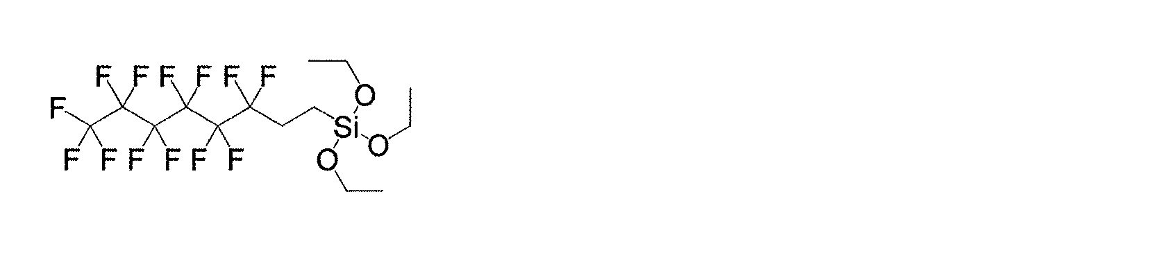
As inorganic fine particle aggregates, hydrophilic fumed silica (manufactured by Nippon Aerosil Co., Ltd., product number "AEROSIL50", BET
具体的には、イソプロパノール832.9gに対して、表面修飾剤40.8g、酢酸22.1g、純水43.2g、及び無機微粒子凝集体80gを加え、24時間撹拌して、無機微粒子凝集体の分散液を得た。次に分散液を100℃で1時間加熱し、さらに200℃で2時間加熱して、表面修飾された無機微粒子凝集体を得た。なお、無機微粒子凝集体の疎水化度(粉体の濡れ性試験)は68質量%であった。 Specifically, 40.8 g of a surface modifier, 22.1 g of acetic acid, 43.2 g of pure water, and 80 g of inorganic fine particle aggregates were added to 832.9 g of isopropanol, and the mixture was stirred for 24 hours to stir the inorganic fine particle aggregates. The dispersion liquid of was obtained. Next, the dispersion was heated at 100 ° C. for 1 hour and then at 200 ° C. for 2 hours to obtain surface-modified inorganic fine particle aggregates. The degree of hydrophobicity of the inorganic fine particle aggregate (powder wettability test) was 68% by mass.
次にV型ミキサを使用して、ポリテトラフルオロエチレンと無機微粒子凝集体と揮発性添加剤を混合した。具体的には、ポリテトラフルオロエチレン(ダイキン社製、品番「ポリフロンPTFE F-104」、平均粒子径550μm)を、固形分を考慮して、ポリテトラフルオロエチレンと得られた無機微粒子凝集体とが質量比40:60になるように加え、揮発性添加剤としてドデカンを、ポリテトラフルオロエチレンと無機微粒子凝集体の合計を100質量部としたときに50質量部になるように加え、回転数10rpm、温度24℃で5分間混合してペーストを得た。 Next, a V-type mixer was used to mix polytetrafluoroethylene, inorganic fine particle aggregates, and volatile additives. Specifically, polytetrafluoroethylene (manufactured by Daikin Co., Ltd., product number "Polyflon PTFE F-104", average particle size 550 μm) is mixed with polytetrafluoroethylene and the obtained inorganic fine particle aggregates in consideration of the solid content. Was added so that the mass ratio was 40:60, and dodecane was added as a volatile additive so that the total of polytetrafluoroethylene and inorganic fine particle aggregates was 100 parts by mass, and the number of revolutions was 50 parts by mass. A paste was obtained by mixing at 10 rpm and a temperature of 24 ° C. for 5 minutes.
ペーストを1対の圧延ロールに通して、厚み3mm、幅10~50mm、長さ150mmの楕円状母シート(シート状成形体)にし、この母シートを複数枚作製した。次に、この母シートの圧延方向を揃えて2枚積層し、この積層物を先の圧延方向のまま上記圧延ロール間に通して圧延し、第1の圧延積層シートを作製した。この第1の圧延積層シートを複数枚作製した。次に、2枚の第1の圧延積層シートの圧延方向を揃えて積層し、シート面は平行のまま先の圧延方向から積層シートを90度回転させて上記圧延ロール間に通して圧延し、第2の圧延積層シートを作製した。第2の圧延積層シートを複数枚作製した。さらに、2枚の第2の圧延積層シートを、上記第2の圧延積層シートの作製方法と同様にして圧延し、第3の圧延積層シートを作製した。このように、シートを積層し圧延する工程を、母シートの積層圧延から数えて合計5回繰り返した後、上記圧延ロール間のギャップを0.5mmずつ狭めて複数回圧延し、厚み約0.18mmのシートを得た(構成層数32層)。 The paste was passed through a pair of rolling rolls to form an elliptical mother sheet (sheet-shaped molded product) having a thickness of 3 mm, a width of 10 to 50 mm, and a length of 150 mm, and a plurality of the mother sheets were prepared. Next, two sheets of the mother sheet were laminated in the same rolling direction, and the laminate was passed between the rolling rolls in the same rolling direction and rolled to prepare a first rolled laminated sheet. A plurality of the first rolled laminated sheets were produced. Next, the two first rolled laminated sheets are laminated by aligning the rolling directions, and the laminated sheets are rotated 90 degrees from the previous rolling direction while keeping the sheet surfaces parallel, and the laminated sheets are passed between the rolling rolls and rolled. A second rolled laminated sheet was produced. A plurality of second rolled laminated sheets were produced. Further, the two second rolled laminated sheets were rolled in the same manner as in the method for producing the second rolled laminated sheet to prepare a third rolled laminated sheet. In this way, the process of laminating and rolling the sheets is repeated a total of 5 times counting from the laminating rolling of the mother sheet, and then the gap between the rolling rolls is narrowed by 0.5 mm and rolled a plurality of times to obtain a thickness of about 0. An 18 mm sheet was obtained (32 constituent layers).
得られた圧延積層シートを150℃で20分間加熱して揮発性添加剤を除去し、得られたシートを380℃で5分間、1MPaで加圧成形して、厚み約0.15mmの板状の複合材料を作製した。 The obtained rolled laminated sheet was heated at 150 ° C. for 20 minutes to remove volatile additives, and the obtained sheet was pressure-molded at 380 ° C. for 5 minutes at 1 MPa to form a plate having a thickness of about 0.15 mm. The composite material of was prepared.
得られた複合材料について、下記の通りに気孔率、疎水化度、臨界撥液張力、比誘電率・誘電正接、及び熱線膨張率を測定するとともに、クリーナー・コンディショナー液に浸漬させた場合の質量変化率を測定した。なお、疎水化度は充填剤について測定した。結果を表1に示す。 For the obtained composite material, the porosity, hydrophobicity, critical liquid repellent tension, relative permittivity / dielectric loss tangent, and heat ray expansion rate were measured as follows, and the mass when immersed in a cleaner / conditioner solution. The rate of change was measured. The degree of hydrophobicity was measured for the filler. The results are shown in Table 1.
(気孔率)
複合材料の体積、ポリテトラフルオロエチレン(PTFE)の比重と質量(配合質量)、無機微粒子凝集体の比重と質量(配合質量)を測定し、下記式に代入することによって気孔率を算出した。
[気孔率(%)]=([複合材料の体積]-[PTFEの質量/PTFEの比重]-[無機微粒子凝集体の質量/無機微粒子凝集体の比重])/[複合材料の体積]×100(Porosity)
The volume of the composite material, the specific gravity and mass (blended mass) of polytetrafluoroethylene (PTFE), and the specific gravity and mass (blended mass) of the inorganic fine particle aggregates were measured, and the pore ratio was calculated by substituting into the following formula.
[Pore ratio (%)] = ([Volume of composite material]-[Mass of PTFE / Specific density of PTFE]-[Mass of inorganic fine particle aggregates / Specific gravity of inorganic fine particle aggregates]) / [Volume of composite material] × 100
(疎水化度)
充填剤の疎水化度は、25℃において粉体をメタノール水溶液に散布し、粉体の浮遊量が0質量%となるときのメタノール水溶液におけるメタノール濃度を決定することによって算出した。(Degree of hydrophobization)
The degree of hydrophobicity of the filler was calculated by spraying the powder on the aqueous methanol solution at 25 ° C. and determining the concentration of methanol in the aqueous methanol solution when the floating amount of the powder was 0% by mass.
(臨界撥液張力)
複合材料を和光純薬工業社製の「ぬれ張力試験用混合液」に室温で1分間浸漬させた後、蒸留水により洗浄し、複合材料に濡れ張力試験用混合液が浸透しているかを目視で判断した。ぬれ張力試験用混合液はNo.22.6~50.0を使用し、浸透が見られなかったぬれ張力試験用混合液のうち、最も表面張力の低い試験液の数値を臨界撥液張力の結果とした。(Critical liquid repellent tension)
After immersing the composite material in a "wetting tension test mixture" manufactured by Wako Pure Chemical Industries, Ltd. for 1 minute at room temperature, wash it with distilled water and visually check whether the wet tension test mixture has penetrated into the composite material. Judged by. The mixed solution for the wetting tension test is No. From 22.6 to 50.0, the value of the test solution having the lowest surface tension among the mixed solutions for the wet tension test in which penetration was not observed was taken as the result of the critical liquid repellent tension.
(比誘電率・誘電正接)
測定周波数を10GHzとし、空洞共振器摂動法により複素誘電率を測定し、その実数部(εr’)を比誘電率とした。また、実数部に対する虚数部(εr”)の比(εr”/εr’)から誘電正接を求めた。
比誘電率測定装置(アジレント・テクノロジー社製「ネットワークアナライザN5230C」、及び関東電子応用開発社製「空洞共振器10GHz」)を用い、各シートから短冊状のサンプル(サンプルサイズ幅2mm×長さ70mm)を切り出し測定した。(Relative permittivity / dielectric loss tangent)
The measurement frequency was set to 10 GHz, the complex permittivity was measured by the cavity resonator permittivity method, and the real part (εr') of the complex permittivity was taken as the relative permittivity. Further, the dielectric loss tangent was obtained from the ratio (εr ″ / εr') of the imaginary part (εr ″) to the real part.
Using a relative permittivity measuring device (“Network Analyzer N5230C” manufactured by Agilent Technologies and “Cavity Resonator 10 GHz” manufactured by Kanto Electronics Applied Development Co., Ltd.), a strip-shaped sample (sample size width 2 mm × length 70 mm) from each sheet ) Was cut out and measured.
(熱線膨張率)
TMA法にて、熱機械分析装置(BRUKER AXS社製、「TMA4000SA」)を用い、-50~200℃のシート平面方向の平均熱線膨張率を、熱線膨張率(ppm/K)とした。具体的には、幅4mm、長さ20mmの複合材料を長さ方向に固定し、2gの荷重をかけ、室温から昇温速度10℃/minで200℃まで昇温し、30分間保持することで材料の残留応力を除去する。次いで、10℃/minで-50℃まで冷却し、15分間保持した後、2℃/minで200℃まで昇温させる。2回目の昇温過程における-50~200℃の平均熱線膨張率を熱線膨張率とした。(Coefficient of thermal expansion)
In the TMA method, a thermomechanical analyzer (“TMA4000SA” manufactured by BRUKER AXS) was used, and the average coefficient of linear thermal expansion in the sheet plane direction at −50 to 200 ° C. was defined as the coefficient of linear thermal expansion (ppm / K). Specifically, a composite material having a width of 4 mm and a length of 20 mm is fixed in the length direction, a load of 2 g is applied, the temperature is raised from room temperature to 200 ° C. at a heating rate of 10 ° C./min, and the mixture is held for 30 minutes. Removes the residual stress of the material with. Then, it is cooled to −50 ° C. at 10 ° C./min, held for 15 minutes, and then heated to 200 ° C. at 2 ° C./min. The average coefficient of linear thermal expansion at −50 to 200 ° C. in the second heating process was defined as the coefficient of linear thermal expansion.
(クリーナー・コンディショナー溶液(CC溶液)浸漬試験による質量変化率)
電子回路加工に使用される比較的浸透性の高い溶液である、無電解めっき前処理用の界面活性剤を含有するクリーナー・コンディショナー溶液(ロームアンドハース電子材料社製、CIRCUPOSIT(登録商標) CONDITIONER-NETRALIZER 3320)を使用して、得られた複合材料の溶液浸漬による質量変化率を測定した。具体的には、予め複合材料の質量を測定しておき、次にクリーナー・コンディショナー溶液とイオン交換水の混合溶液(体積比10:90)に45℃で5分間浸漬させ、イオン交換水ですすいで表面水分を拭き取り、質量を測定して質量変化率を算出する手順である。(Mass change rate by immersion test of cleaner / conditioner solution (CC solution))
Cleaner / conditioner solution containing a surfactant for electroplating pretreatment, which is a relatively permeable solution used for electronic circuit processing (CIRCUPOSIT® CONDITIONER-, manufactured by Roam & Haas Electronic Materials Co., Ltd.) Using NETRALIZER 3320), the rate of change in mass of the obtained composite material due to solution immersion was measured. Specifically, the mass of the composite material is measured in advance, then immersed in a mixed solution of cleaner / conditioner solution and ion-exchanged water (volume ratio 10:90) at 45 ° C. for 5 minutes, and rinsed with ion-exchanged water. It is a procedure to wipe off the surface moisture with and measure the mass to calculate the mass change rate.
<実施例2>
ポリテトラフルオロエチレンと無機微粒子凝集体の合計を100質量部としたときに、ドデカンを45質量部となるように加えた以外、実施例1と同様の方法により複合材料を作製した。結果を表1に示す。<Example 2>
When the total amount of the polytetrafluoroethylene and the inorganic fine particle aggregate was 100 parts by mass, a composite material was prepared by the same method as in Example 1 except that dodecane was added so as to be 45 parts by mass. The results are shown in Table 1.
<実施例3>
ポリテトラフルオロエチレンと無機微粒子凝集体の合計を100質量部としたときに、ドデカンが40質量部となるように加えた以外、実施例1と同様の方法により複合材料を作製した。結果を表1に示す。<Example 3>
When the total amount of the polytetrafluoroethylene and the inorganic fine particle aggregate was 100 parts by mass, a composite material was prepared by the same method as in Example 1 except that dodecane was added so as to be 40 parts by mass. The results are shown in Table 1.
<実施例4>
表面修飾剤を3M社製Novec(登録商標)2202に変更し、表面修飾の方法を下記のように変更した以外、実施例3と同様の方法により複合材料を作製した。表面修飾は、無機微粒子凝集体100質量部に対してNovec(登録商標)2202の固形分が25質量部となるように無機微粒子凝集体を混合分散させて行った。結果を表1に示す。<Example 4>
A composite material was produced by the same method as in Example 3 except that the surface modifier was changed to Novec (registered trademark) 2202 manufactured by 3M Co., Ltd. and the surface modification method was changed as follows. The surface modification was carried out by mixing and dispersing the inorganic fine particle aggregates so that the solid content of Novec (registered trademark) 2202 was 25 parts by mass with respect to 100 parts by mass of the inorganic fine particle aggregates. The results are shown in Table 1.
<実施例5>
無機微粒子凝集体を、アミノシラン((C2H5O)3SiC3H6NH2)とヘキサメチルジシラザン(HMDS)で処理されている疎水性フュームドシリカ(日本アエロジル社製、品番「AEROSIL NA50H」、BET比表面積40±10m2/g、見かけ比重50g/L)に変更した以外、実施例4と同様の方法により複合材料を作製した。結果を表1に示す。<Example 5>
Hydrophobic fumed silica (manufactured by Nippon Aerosil Co., Ltd., product number "AEROSIL") in which inorganic fine particle aggregates are treated with aminosilane ((C 2 H 5 O) 3 SiC 3 H 6 NH 2 ) and hexamethyldisilazane (HMDS). A composite material was prepared by the same method as in Example 4 except that it was changed to "NA50H", BET specific surface area 40 ± 10 m 2 / g, and apparent specific gravity 50 g / L). The results are shown in Table 1.
<実施例6>
無機微粒子凝集体を、アミノシラン((C2H5O)3SiC3H6NH2)とヘキサメチルジシラザン(HMDS)で処理されている疎水性フュームドシリカ(日本アエロジル社製、品番「AEROSIL NA50H」、BET比表面積40±10m2/g、見かけ比重50g/L)に変更した以外、実施例2と同様の方法により複合材料を作製した。結果を表2に示す。<Example 6>
Hydrophobic fumed silica (manufactured by Nippon Aerosil Co., Ltd., product number "AEROSIL") in which inorganic fine particle aggregates are treated with aminosilane ((C 2 H 5 O) 3 SiC 3 H 6 NH 2 ) and hexamethyldisilazane (HMDS). A composite material was prepared by the same method as in Example 2 except that it was changed to "NA50H", BET specific surface area 40 ± 10 m 2 / g, and apparent specific gravity 50 g / L). The results are shown in Table 2.
<比較例1>
無機微粒子凝集体を、ジメチルポリシロキサン(シリコーンオイル)で処理されている疎水性フュームドシリカ(日本アエロジル社製、品番「AEROSIL NY50」、BET比表面積30±10m2/g、見かけ比重50g/L、一次粒子の平均粒子径40nm)に変更し、表面修飾剤(トリエトキシ-1H,1H,2H,2H-トリデカフルオロ-n-オクチルシラン)で表面修飾しなかった以外、実施例1と同様の方法により複合材料を作製した。結果を表2に示す。<Comparative example 1>
Hydrophobic fumed silica (manufactured by Nippon Aerosil Co., Ltd., product number "AEROSIL NY50") in which inorganic fine particle aggregates are treated with dimethylpolysiloxane (silicone oil), BET
<比較例2>
無機微粒子凝集体を、ヘキサメチルジシラザン(HMDS)で処理されている疎水性フュームドシリカ(日本アエロジル社製、品番「AEROSIL NAX50」、BET比表面積40±10m2/g、見かけ比重40g/L、一次粒子の平均粒子径40nm)に変更し、表面修飾剤(トリエトキシ-1H,1H,2H,2H-トリデカフルオロ-n-オクチルシラン)で表面修飾しなかった以外、実施例1と同様の方法により複合材料を作製した。結果を表2に示す。<Comparative example 2>
Hydrophobic fumed silica (manufactured by Nippon Aerosil Co., Ltd., product number "AEROSIL NAX50") in which inorganic fine particle aggregates are treated with hexamethyldisilazane (HMDS), BET specific surface area 40 ± 10 m 2 / g, apparent specific gravity 40 g / L , The average particle size of the primary particles is 40 nm), and the surface is not modified with a surface modifier (triethoxy-1H, 1H, 2H, 2H-tridecafluoro-n-octylsilane), but the same as in Example 1. A composite material was prepared by the method. The results are shown in Table 2.
<比較例3>
無機微粒子凝集体を、ジメチルポリシロキサン(シリコーンオイル)で処理されている疎水性フュームドシリカ(日本アエロジル社製、品番「AEROSIL RY200S」、BET比表面積80±15m2/g、見かけ比重50g/L、一次粒子の平均粒子径10nm)に変更し、表面修飾剤(トリエトキシ-1H,1H,2H,2H-トリデカフルオロ-n-オクチルシラン)で表面修飾しなかった以外、実施例1と同様の方法により複合材料を作製した。結果を表2に示す。<Comparative example 3>
Hydrophobic fumed silica (manufactured by Nippon Aerosil Co., Ltd., product number "AEROSIL RY200S") in which inorganic fine particle aggregates are treated with dimethylpolysiloxane (silicone oil), BET specific surface area 80 ± 15 m 2 / g, apparent specific gravity 50 g / L , Average particle size of primary particles (10 nm)), and the same as in Example 1 except that the surface was not modified with a surface modifier (triethoxy-1H, 1H, 2H, 2H-tridecafluoro-n-octylsilane). A composite material was prepared by the method. The results are shown in Table 2.
<比較例4>
無機微粒子凝集体を、ヘキサメチルジシラザン(HMDS)で処理されている疎水性フュームドシリカ(日本アエロジル社製、品番「AEROSIL RX300」、BET比表面積200±20m2/g、見かけ比重40g/L、一次粒子の平均粒子径8nm)に変更し、表面修飾剤(トリエトキシ-1H,1H,2H,2H-トリデカフルオロ-n-オクチルシラン)で表面修飾しなかった以外、実施例2と同様の方法により複合材料を作製した。結果を表2に示す。<Comparative example 4>
Hydrophobic fumed silica (manufactured by Nippon Aerosil Co., Ltd., product number "AEROSIL RX300") in which inorganic fine particle aggregates are treated with hexamethyldisilazane (HMDS), BET specific surface area 200 ± 20 m 2 / g, apparent specific gravity 40 g / L , Average particle size of primary particles (8 nm)), and the same as in Example 2 except that the surface was not modified with a surface modifier (triethoxy-1H, 1H, 2H, 2H-tridecafluoro-n-octylsilane). A composite material was prepared by the method. The results are shown in Table 2.
<比較例5>
無機微粒子凝集体をシリカエアロゲルに変更し、表面修飾剤で表面修飾しなかった以外、実施例3と同様の方法により複合材料を作製した。結果を表3に示す。<Comparative example 5>
A composite material was prepared by the same method as in Example 3 except that the inorganic fine particle aggregate was changed to silica airgel and the surface was not modified with a surface modifier. The results are shown in Table 3.
<比較例6>
無機微粒子凝集体を中空シリカ(3M社製、iM16K)に変更し、表面修飾剤で表面修飾せず、さらにポリテトラフルオロエチレンと中空シリカの合計を100質量部としたときに、ドデカンを55質量部となるように加えた以外、実施例1と同様の方法により複合材料を作製した。結果を表3に示す。<Comparative Example 6>
When the inorganic fine particle agglomerates were changed to hollow silica (3M, iM16K), the surface was not modified with a surface modifier, and the total of polytetrafluoroethylene and hollow silica was 100 parts by mass, 55 mass of dodecane was added. A composite material was prepared by the same method as in Example 1 except that the particles were added so as to form parts. The results are shown in Table 3.


実施例は何れも、低い比誘電率を示すとともに、CC溶液にさらされた場合に外観不良や特性変化が生じにくい複合材料であり、電子回路基板用として適材であることがわかった。これに対し、比較例1~5はCC溶液浸漬試験により質量変化率が大きいものであり、また、比較例6は熱線膨張率が高く、実用に向かないものであった。 It was found that all of the examples are composite materials that show a low relative permittivity and are less likely to cause poor appearance or change in characteristics when exposed to a CC solution, and are suitable for electronic circuit boards. On the other hand, Comparative Examples 1 to 5 had a large mass change rate in the CC solution immersion test, and Comparative Example 6 had a high coefficient of linear thermal expansion, which was not suitable for practical use.
上記実施例においては、本発明における具体的な形態について示したが、上記実施例は単なる例示にすぎず、限定的に解釈されるものではない。当業者に明らかな様々な変形は、本発明の範囲内であることが企図されている。 Although the specific embodiments of the present invention have been shown in the above examples, the above examples are merely examples and are not to be interpreted in a limited manner. Various modifications apparent to those skilled in the art are intended to be within the scope of the present invention.
本発明の複合材料は、携帯電話、コンピュータ、アンテナ等のモジュールの配線基板、特にミリ波アンテナの配線基板(高周波用配線基板)に好適である。 The composite material of the present invention is suitable for wiring substrates of modules such as mobile phones, computers, and antennas, particularly wiring substrates for millimeter-wave antennas (wiring substrates for high frequencies).
Claims (5)
前記充填剤が、平均一次粒子径5~200nmの無機微粒子が凝集して形成された多孔性無機微粒子凝集体を含み、
前記複合材料の気孔率が35%以上であり、かつ
下記のぬれ張力試験によって決定される臨界撥液張力が、34.0mN/m以下である
ことを特徴とする、複合材料。
[ぬれ張力試験]
日本工業規格JISK6768:1999に記載の試験用混合液に該当し、23℃におけるぬれ張力が22.6mN/m、25.4mN/m、27.3mN/m、30.0mN/m、31.0mN/m、32.0mN/m、33.0mN/m、34.0mN/m、35.0mN/m、36.0mN/m、37.0mN/m、38.0mN/m、39.0mN/m、40.0mN/m、41.0mN/m、42.0mN/m、43.0mN/m、44.0mN/m、45.0mN/m、46.0mN/m、48.0mN/m、及び50.0mN/mである試験用混合液のそれぞれに、被検体を25℃で1分間浸漬して、それぞれの試験用混合液が前記被検体に浸透するか否かを確認し、前記被検体に浸透しなかった試験用混合液のうちの最もぬれ張力が小さいもののぬれ張力の数値をその被検体の臨界撥液張力と決定する。A plate-shaped composite material containing polytetrafluoroethylene and a filler.
The filler contains a porous inorganic fine particle agglomerate formed by aggregating inorganic fine particles having an average primary particle diameter of 5 to 200 nm.
The composite material is characterized in that the porosity of the composite material is 35% or more, and the critical liquid repellent tension determined by the following wetting tension test is 34.0 mN / m or less.
[Wet tension test]
It corresponds to the test mixture described in Japanese Industrial Standard JIS K6768: 1999, and the wetting tension at 23 ° C. is 22.6 mN / m, 25.4 mN / m, 27.3 mN / m, 30.0 mN / m, 31.0 mN. / M, 32.0 mN / m, 33.0 mN / m, 34.0 mN / m, 35.0 mN / m, 36.0 mN / m, 37.0 mN / m, 38.0 mN / m, 39.0 mN / m , 40.0 mN / m, 41.0 mN / m, 42.0 mN / m, 43.0 mN / m, 44.0 mN / m, 45.0 mN / m, 46.0 mN / m, 48.0 mN / m, and The subject was immersed in each of the test mixed solutions having a temperature of 50.0 mN / m at 25 ° C. for 1 minute, and it was confirmed whether or not each test mixed solution permeated the subject. The value of the wetting tension of the test mixture having the smallest wetting tension is determined as the critical liquid repellent tension of the subject.
The composite material according to any one of claims 1 to 4, which is used for an electronic circuit board.
Applications Claiming Priority (9)
| Application Number | Priority Date | Filing Date | Title |
|---|---|---|---|
| JP2017108332 | 2017-05-31 | ||
| JP2017108332 | 2017-05-31 | ||
| US201762560432P | 2017-09-19 | 2017-09-19 | |
| US62/560,432 | 2017-09-19 | ||
| US201762567966P | 2017-10-04 | 2017-10-04 | |
| US62/567,966 | 2017-10-04 | ||
| US201862619562P | 2018-01-19 | 2018-01-19 | |
| US62/619,562 | 2018-01-19 | ||
| PCT/JP2018/020672 WO2018221556A1 (en) | 2017-05-31 | 2018-05-30 | Tabular composite material containing polytetrafluoroethylene and filler |
Publications (2)
| Publication Number | Publication Date |
|---|---|
| JPWO2018221556A1 JPWO2018221556A1 (en) | 2020-04-02 |
| JP7102402B2 true JP7102402B2 (en) | 2022-07-19 |
Family
ID=65803472
Family Applications (1)
| Application Number | Title | Priority Date | Filing Date |
|---|---|---|---|
| JP2019521255A Active JP7102402B2 (en) | 2017-05-31 | 2018-05-30 | Plate-like composite material containing polytetrafluoroethylene and filler |
Country Status (5)
| Country | Link |
|---|---|
| US (1) | US11453762B2 (en) |
| EP (1) | EP3632980A4 (en) |
| JP (1) | JP7102402B2 (en) |
| KR (1) | KR102477336B1 (en) |
| TW (1) | TWI768053B (en) |
Families Citing this family (2)
| Publication number | Priority date | Publication date | Assignee | Title |
|---|---|---|---|---|
| KR20210040369A (en) | 2018-07-31 | 2021-04-13 | 닛토덴코 가부시키가이샤 | Plate-like composite material |
| JPWO2021235276A1 (en) * | 2020-05-18 | 2021-11-25 |
Citations (7)
| Publication number | Priority date | Publication date | Assignee | Title |
|---|---|---|---|---|
| JP2001176329A (en) | 1999-12-14 | 2001-06-29 | Asahi Glass Co Ltd | Low dielectric material |
| JP2001358415A (en) | 2000-06-16 | 2001-12-26 | Nippon Pillar Packing Co Ltd | Printed circuit board |
| WO2005019320A1 (en) | 2003-08-25 | 2005-03-03 | Daikin Industries, Ltd. | Mixed polytetrafluoroethylene powder, polytetrafluoroethylene porous shaped body, methods for producing those, polytetrafluoroethylene porous foam shaped body, and product for high-frequency signal transmission |
| JP2005163006A (en) | 2003-12-04 | 2005-06-23 | Chung Yuan Christian Univ | Mesoporous silica/fluoridated polymer composite material |
| JP2007026922A (en) | 2005-07-19 | 2007-02-01 | Sumitomo Electric Ind Ltd | Composite porous resin base material and its manufacturing method |
| JP2013165171A (en) | 2012-02-10 | 2013-08-22 | Sumitomo Electric Ind Ltd | Base material for printed wiring board and manufacturing method of the same |
| JP2015209480A (en) | 2014-04-25 | 2015-11-24 | 三井・デュポンフロロケミカル株式会社 | Fluororesin composition |
Family Cites Families (13)
| Publication number | Priority date | Publication date | Assignee | Title |
|---|---|---|---|---|
| US3915916A (en) | 1974-05-24 | 1975-10-28 | Du Pont | Process for reducing filler loss |
| JPS6021694B2 (en) | 1980-07-08 | 1985-05-29 | ダイキン工業株式会社 | Method for manufacturing filler-containing polytetrafluoroethylene molding powder |
| CA1341552C (en) | 1988-09-23 | 2007-10-02 | Kenneth Alonso | Method of producing human-human hybridomas, the production of monoclonal and polyclonal antibodies therefrom, and therapeutic use thereof |
| JPH03212987A (en) | 1990-01-17 | 1991-09-18 | Matsushita Electric Works Ltd | Composite material for electrical use, laminated sheet and printed wiring board |
| US5055342A (en) | 1990-02-16 | 1991-10-08 | International Business Machines Corporation | Fluorinated polymeric composition, fabrication thereof and use thereof |
| JPH06119810A (en) | 1990-02-21 | 1994-04-28 | Rogers Corp | Dielectric composite |
| US5354611A (en) | 1990-02-21 | 1994-10-11 | Rogers Corporation | Dielectric composite |
| US5506049C1 (en) * | 1991-05-24 | 2001-05-29 | World Properties Inc | Particulate filled composite film and method of making same |
| EP0604799A1 (en) * | 1992-12-29 | 1994-07-06 | International Business Machines Corporation | Coated filler and use thereof |
| JPH08157643A (en) * | 1994-12-07 | 1996-06-18 | Asahi Glass Co Ltd | Water-repellent/oil-repellent porous silica particle and water-repellent/oil-repellent coating film |
| CN103328382A (en) * | 2011-01-21 | 2013-09-25 | Dic株式会社 | Process for producing porous silica particles, resin composition for antireflection coatings, article with antireflection coating, and antireflection film |
| CN104479266A (en) | 2014-12-26 | 2015-04-01 | 天津滨浦生产力促进有限公司 | Surface modification method of inorganic nanoparticles as well as polytetrafluoroethylene/inorganic nanoparticle composite material |
| CN106009428B (en) | 2016-05-13 | 2018-02-13 | 电子科技大学 | A kind of silica-filled PTFE composite and preparation method thereof |
-
2018
- 2018-05-30 TW TW107118530A patent/TWI768053B/en active
- 2018-05-30 EP EP18810405.3A patent/EP3632980A4/en active Pending
- 2018-05-30 KR KR1020197035341A patent/KR102477336B1/en active IP Right Grant
- 2018-05-30 US US16/615,623 patent/US11453762B2/en active Active
- 2018-05-30 JP JP2019521255A patent/JP7102402B2/en active Active
Patent Citations (7)
| Publication number | Priority date | Publication date | Assignee | Title |
|---|---|---|---|---|
| JP2001176329A (en) | 1999-12-14 | 2001-06-29 | Asahi Glass Co Ltd | Low dielectric material |
| JP2001358415A (en) | 2000-06-16 | 2001-12-26 | Nippon Pillar Packing Co Ltd | Printed circuit board |
| WO2005019320A1 (en) | 2003-08-25 | 2005-03-03 | Daikin Industries, Ltd. | Mixed polytetrafluoroethylene powder, polytetrafluoroethylene porous shaped body, methods for producing those, polytetrafluoroethylene porous foam shaped body, and product for high-frequency signal transmission |
| JP2005163006A (en) | 2003-12-04 | 2005-06-23 | Chung Yuan Christian Univ | Mesoporous silica/fluoridated polymer composite material |
| JP2007026922A (en) | 2005-07-19 | 2007-02-01 | Sumitomo Electric Ind Ltd | Composite porous resin base material and its manufacturing method |
| JP2013165171A (en) | 2012-02-10 | 2013-08-22 | Sumitomo Electric Ind Ltd | Base material for printed wiring board and manufacturing method of the same |
| JP2015209480A (en) | 2014-04-25 | 2015-11-24 | 三井・デュポンフロロケミカル株式会社 | Fluororesin composition |
Also Published As
| Publication number | Publication date |
|---|---|
| EP3632980A1 (en) | 2020-04-08 |
| KR20200016230A (en) | 2020-02-14 |
| KR102477336B1 (en) | 2022-12-13 |
| TWI768053B (en) | 2022-06-21 |
| TW201902965A (en) | 2019-01-16 |
| US20200079931A1 (en) | 2020-03-12 |
| JPWO2018221556A1 (en) | 2020-04-02 |
| EP3632980A4 (en) | 2021-03-10 |
| US11453762B2 (en) | 2022-09-27 |
Similar Documents
| Publication | Publication Date | Title |
|---|---|---|
| WO2018221556A1 (en) | Tabular composite material containing polytetrafluoroethylene and filler | |
| JP7200197B2 (en) | Insulating resin material, insulating resin material with metal layer and wiring substrate using the same | |
| JP7102402B2 (en) | Plate-like composite material containing polytetrafluoroethylene and filler | |
| WO2021070805A1 (en) | Plate-shaped composite material | |
| WO2020213669A1 (en) | Plate-shaped composite material | |
| WO2017018105A1 (en) | Fluororesin porous body, metal layer-equipped porous body using same, and wiring substrate | |
| JP2005163006A (en) | Mesoporous silica/fluoridated polymer composite material | |
| JP7187562B2 (en) | Plate-shaped composite material | |
| WO2017159816A1 (en) | Insulating resin material, metal-layer-attached insulating resin material using same, and wiring substrate | |
| TWI850477B (en) | Plate-like composite materials | |
| JP2024081999A (en) | Fluororesin composition, laminate for substrates and printed wiring board | |
| WO2024128221A1 (en) | Composition, sheet and method for producing same | |
| TW202428759A (en) | Composition, fluororesin sheet and manufacturing method thereof | |
| JP2022069962A (en) | Dispersion and method for producing laminate |
Legal Events
| Date | Code | Title | Description |
|---|---|---|---|
| A521 | Request for written amendment filed |
Free format text: JAPANESE INTERMEDIATE CODE: A821 Effective date: 20190718 |
|
| A621 | Written request for application examination |
Free format text: JAPANESE INTERMEDIATE CODE: A621 Effective date: 20210415 |
|
| A131 | Notification of reasons for refusal |
Free format text: JAPANESE INTERMEDIATE CODE: A131 Effective date: 20220419 |
|
| A521 | Request for written amendment filed |
Free format text: JAPANESE INTERMEDIATE CODE: A821 Effective date: 20220616 |
|
| TRDD | Decision of grant or rejection written | ||
| A01 | Written decision to grant a patent or to grant a registration (utility model) |
Free format text: JAPANESE INTERMEDIATE CODE: A01 Effective date: 20220705 |
|
| A61 | First payment of annual fees (during grant procedure) |
Free format text: JAPANESE INTERMEDIATE CODE: A61 Effective date: 20220706 |
|
| R150 | Certificate of patent or registration of utility model |
Ref document number: 7102402 Country of ref document: JP Free format text: JAPANESE INTERMEDIATE CODE: R150 |