JP7082482B2 - Disc scanning microscope system, program - Google Patents
Disc scanning microscope system, program Download PDFInfo
- Publication number
- JP7082482B2 JP7082482B2 JP2017243442A JP2017243442A JP7082482B2 JP 7082482 B2 JP7082482 B2 JP 7082482B2 JP 2017243442 A JP2017243442 A JP 2017243442A JP 2017243442 A JP2017243442 A JP 2017243442A JP 7082482 B2 JP7082482 B2 JP 7082482B2
- Authority
- JP
- Japan
- Prior art keywords
- optical system
- observation mode
- disk
- super
- magnification
- Prior art date
- Legal status (The legal status is an assumption and is not a legal conclusion. Google has not performed a legal analysis and makes no representation as to the accuracy of the status listed.)
- Active
Links
Images


Classifications
-
- G—PHYSICS
- G02—OPTICS
- G02B—OPTICAL ELEMENTS, SYSTEMS OR APPARATUS
- G02B21/00—Microscopes
- G02B21/0004—Microscopes specially adapted for specific applications
- G02B21/002—Scanning microscopes
- G02B21/0024—Confocal scanning microscopes (CSOMs) or confocal "macroscopes"; Accessories which are not restricted to use with CSOMs, e.g. sample holders
- G02B21/0036—Scanning details, e.g. scanning stages
-
- G—PHYSICS
- G02—OPTICS
- G02B—OPTICAL ELEMENTS, SYSTEMS OR APPARATUS
- G02B21/00—Microscopes
- G02B21/0004—Microscopes specially adapted for specific applications
- G02B21/002—Scanning microscopes
- G02B21/0024—Confocal scanning microscopes (CSOMs) or confocal "macroscopes"; Accessories which are not restricted to use with CSOMs, e.g. sample holders
- G02B21/0052—Optical details of the image generation
- G02B21/0076—Optical details of the image generation arrangements using fluorescence or luminescence
-
- G—PHYSICS
- G02—OPTICS
- G02B—OPTICAL ELEMENTS, SYSTEMS OR APPARATUS
- G02B21/00—Microscopes
- G02B21/0004—Microscopes specially adapted for specific applications
- G02B21/002—Scanning microscopes
- G02B21/0024—Confocal scanning microscopes (CSOMs) or confocal "macroscopes"; Accessories which are not restricted to use with CSOMs, e.g. sample holders
- G02B21/0032—Optical details of illumination, e.g. light-sources, pinholes, beam splitters, slits, fibers
-
- G—PHYSICS
- G02—OPTICS
- G02B—OPTICAL ELEMENTS, SYSTEMS OR APPARATUS
- G02B21/00—Microscopes
- G02B21/0004—Microscopes specially adapted for specific applications
- G02B21/002—Scanning microscopes
- G02B21/0024—Confocal scanning microscopes (CSOMs) or confocal "macroscopes"; Accessories which are not restricted to use with CSOMs, e.g. sample holders
- G02B21/0036—Scanning details, e.g. scanning stages
- G02B21/0044—Scanning details, e.g. scanning stages moving apertures, e.g. Nipkow disks, rotating lens arrays
-
- G—PHYSICS
- G02—OPTICS
- G02B—OPTICAL ELEMENTS, SYSTEMS OR APPARATUS
- G02B21/00—Microscopes
- G02B21/0004—Microscopes specially adapted for specific applications
- G02B21/002—Scanning microscopes
- G02B21/0024—Confocal scanning microscopes (CSOMs) or confocal "macroscopes"; Accessories which are not restricted to use with CSOMs, e.g. sample holders
- G02B21/0052—Optical details of the image generation
- G02B21/0072—Optical details of the image generation details concerning resolution or correction, including general design of CSOM objectives
-
- G—PHYSICS
- G02—OPTICS
- G02B—OPTICAL ELEMENTS, SYSTEMS OR APPARATUS
- G02B21/00—Microscopes
- G02B21/36—Microscopes arranged for photographic purposes or projection purposes or digital imaging or video purposes including associated control and data processing arrangements
- G02B21/361—Optical details, e.g. image relay to the camera or image sensor
-
- G—PHYSICS
- G02—OPTICS
- G02B—OPTICAL ELEMENTS, SYSTEMS OR APPARATUS
- G02B21/00—Microscopes
- G02B21/36—Microscopes arranged for photographic purposes or projection purposes or digital imaging or video purposes including associated control and data processing arrangements
- G02B21/365—Control or image processing arrangements for digital or video microscopes
-
- G—PHYSICS
- G02—OPTICS
- G02B—OPTICAL ELEMENTS, SYSTEMS OR APPARATUS
- G02B27/00—Optical systems or apparatus not provided for by any of the groups G02B1/00 - G02B26/00, G02B30/00
- G02B27/58—Optics for apodization or superresolution; Optical synthetic aperture systems
Description
観察物体の超解像を得るディスク走査型顕微鏡システム、そのシステムを制御するプログラムに関する。 The present invention relates to a disk scanning microscope system that obtains super-resolution of an observation object, and a program that controls the system.
ディスク走査型顕微鏡は、結像光学系の焦点位置と共役な位置に設けられた、表面に複数の開口をもつ共焦点板(ディスク)を有する顕微鏡である。この顕微鏡によれば、合焦位置の情報のみを取得できるとともに、ディスクを回転させることにより、ディスクを介して観察物体中の異なる位置の光学像を順次取得することができ、高速な観察を可能とする。 The disk scanning microscope is a microscope provided with a confocal plate (disk) having a plurality of openings on the surface, which is provided at a position conjugate with the focal position of the imaging optical system. According to this microscope, only the in-focus position information can be acquired, and by rotating the disk, optical images of different positions in the observation object can be sequentially acquired through the disk, enabling high-speed observation. And.
また、ディスクの開口をエアリーディスク径に対して十分に小さくすることで、カットオフ周波数を超える周波数成分(超解像成分)を含む光を得られることが知られている。特に、超解像成分を得るためには、開口径はエアリーディスク径の1/2以下であることが望ましいとされる。 Further, it is known that light containing a frequency component (super-resolution component) exceeding the cutoff frequency can be obtained by making the aperture of the disk sufficiently smaller than the diameter of the Airy disk. In particular, in order to obtain a super-resolution component, it is desirable that the aperture diameter is 1/2 or less of the Airy disk diameter.
特許文献1には、ディスク走査型顕微鏡に係る技術が開示されており、スキャンマスクの開口幅を、結像光学系のカットオフ周波数により規定される大きさよりも小さくする例が示されている。
ディスク走査型顕微鏡において、超解像成分を含む画像を得る超解像観察と通常の観察の両方を切り替えて行う場合、実行する観察に応じて、使用者がスキャンディスクへの投影倍率が適切な投影倍率をもつようにその都度調整作業を行う必要が生じる。そのような調整作業を忘れてしまう、または、誤って適切な倍率ではない値にしてしまうと、超解像成分を含む画像を得ることができず撮り直しを行う等、時間のロスが生じる。また、観察方法の切り替えに伴うそのような調整作業自体が煩雑であるという問題もある。 In a disk scanning microscope, when switching between super-resolution observation and normal observation to obtain an image containing super-resolution components, the projection magnification on the scan disk is appropriate for the user depending on the observation to be performed. It will be necessary to perform adjustment work each time to have a projection magnification. If such adjustment work is forgotten, or if the magnification is mistakenly set to a value that is not an appropriate magnification, an image containing a super-resolution component cannot be obtained and re-shooting occurs, resulting in a loss of time. Further, there is also a problem that such adjustment work itself due to switching of observation methods is complicated.
以上の実情を鑑み、本発明では、超解像観察と通常観察とを切り替えて実行可能であり、使用者による調整の手間がかからないディスク走査型顕微鏡システムを提供することを目的とする。 In view of the above circumstances, it is an object of the present invention to provide a disk scanning microscope system that can be executed by switching between super-resolution observation and normal observation, and does not require the trouble of adjustment by the user.
本発明の一態様におけるディスク走査型顕微鏡システムは、観察物体から光を取り込み前記観察物体の光学像を形成する結像光学系と、使用者からの入力に基づき、超解像観察を行う超解像観察モードと、通常観察を行う通常観察モードとを切り替え、切り替えたモードに応じて前記結像光学系を制御する制御装置と、前記結像光学系の前側焦点位置と共役な位置に配置された、遮光部である表面上に複数の開口が形成され、回転するディスクと、を備え、前記結像光学系は、前記ディスクに形成する前記観察物体上の位置の点像である中間像の投影倍率を変更する中間変倍光学系を含み、前記制御装置は、前記超解像観察モード時において前記中間像の投影倍率を、前記中間像が前記開口の2倍以上の大きさとなるように設定し、前記通常観察モード時において前記中間像の投影倍率を、前記超解像観察モード時の前記中間像の投影倍率よりも低倍に設定し、前記中間像の投影倍率が、設定された前記投影倍率となるよう前記中間変倍光学系を制御する。 The disk scanning microscope system according to one aspect of the present invention is a super-resolution observation system based on an imaging optical system that takes in light from an observation object and forms an optical image of the observation object, and an input from a user. The control device that switches between the image observation mode and the normal observation mode for normal observation and controls the imaging optical system according to the switched mode, and is arranged at a position conjugate with the front focal position of the imaging optical system. Further, a disk having a plurality of openings formed on the surface of the light-shielding portion and rotating is provided , and the imaging optical system is an intermediate image which is a point image of a position on the observation object formed on the disk. The control device includes an intermediate variable magnification optical system that changes the projection magnification so that the projection magnification of the intermediate image in the super-resolution observation mode is at least twice the size of the opening. The projection magnification of the intermediate image was set to be lower than the projection magnification of the intermediate image in the super-resolution observation mode, and the projection magnification of the intermediate image was set in the normal observation mode. The intermediate magnification optical system is controlled so as to have the projection magnification .
本発明の一態様におけるプログラムは、観察物体から光を取り込み前記観察物体の光学像を形成する結像光学系、および、前記結像光学系の前側焦点位置と共役な位置に配置された、遮光部である表面上に複数の開口が形成された回転するディスクとを備え、前記結像光学系は、前記ディスクに形成する前記観察物体上の位置の点像である中間像の投影倍率を変更する中間変倍光学系を含むディスク走査型顕微鏡を制御する制御装置に、使用者からの入力に基づき、超解像観察を行う超解像観察モードと、通常観察を行う通常観察モードとを切り替え、切り替えたモードに応じて前記結像光学系を制御し、前記超解像観察モード時において前記中間像の投影倍率を、前記中間像が前記開口の2倍以上の大きさとなるように設定し、前記通常観察モード時において前記中間像の投影倍率を、前記超解像観察モード時の前記中間像の投影倍率よりも低倍に設定し、前記中間像の投影倍率が、設定された前記投影倍率となるよう前記中間変倍光学系を制御する処理を実行させる。 The program according to one aspect of the present invention is arranged at a position conjugate with an imaging optical system that takes in light from an observation object and forms an optical image of the observation object, and a front focal position of the imaging optical system. A rotating disk having a plurality of openings formed on the surface of the light-shielding portion is provided , and the imaging optical system measures the projection magnification of an intermediate image which is a point image of a position on the observation object formed on the disk. The control device that controls the disk scanning microscope including the intermediate magnification optical system to be changed has a super-resolution observation mode for super-resolution observation and a normal observation mode for normal observation based on the input from the user. The imaging optical system is controlled according to the switching mode, and the projection magnification of the intermediate image is set so that the intermediate image is twice or more the size of the opening in the super-resolution observation mode. Then, the projection magnification of the intermediate image in the normal observation mode is set to be lower than the projection magnification of the intermediate image in the super-resolution observation mode, and the projection magnification of the intermediate image is set. A process of controlling the intermediate variable magnification optical system is executed so as to have a projection magnification .
本発明によれば、超解像観察と通常観察とを切り替えて実行可能であり、使用者による調整の手間がかからないディスク走査型顕微鏡システムを提供することができる。 According to the present invention, it is possible to switch between super-resolution observation and normal observation, and it is possible to provide a disk scanning microscope system that does not require the trouble of adjustment by the user.
以下、第1の実施形態におけるディスク走査型顕微鏡システム100について説明する。図1は、ディスク走査型顕微鏡システム100の構成を示す。
Hereinafter, the disk
ディスク走査型顕微鏡システム100は、光源ユニット1、光ファイバー2、ビームエキスパンダ3、共焦点ディスクユニット40、結像光学系30、撮像装置19、制御装置20、モニター31、画像処理ボード32、外部記憶装置33を備える。
The disk
光源ユニット1は、観察物体である標本Sを照明するための照明光を出力する。光ファイバー2は光源ユニット1の照明光を導光し、ビームエキスパンダ3は照明光束を適切な大きさに調整する。
The
結像光学系30は、照明光を標本Sへ照射するとともに標本Sから光(蛍光)を取り込み、その光学像を形成する。結像光学系30が形成した光学像を撮像装置19が検出し画像化することで、標本Sの観察を実行する。
The imaging
結像光学系30は、ビームスプリッタ8、中間変倍光学系10、レンズ15、対物レンズ16、蛍光フィルタ17、レンズ18を有している。
The imaging
共焦点ディスクユニット40は、マイクロレンズアレイディスク4、共焦点ディスク5、モーター6、軸7を有している。マイクロレンズアレイディスク4、及び共焦点ディスク5は、モーター6により軸7を中心として一体に回転移動する。マイクロレンズアレイディスク4は、ディスク表面上に複数の開口を有し、各々の開口上にはマイクロレンズが配置されている。共焦点ディスク5は、マイクロレンズアレイディスク4の開口の直下となる位置にディスク表面上に複数の開口を有している。即ち、マイクロレンズアレイディスク4のマイクロレンズアレイを介した照明光が共焦点ディスク5の開口を通過するように配置されている。マイクロレンズアレイディスク4を有することで、共焦点ディスク5の開口以外の表面上の領域(遮光部)で照明光が遮光されることを防ぎ、照明効率の向上が図ることができる。
The
共焦点ディスク5は、遮光部である表面上に複数の開口が形成されている。共焦点ディスク5は、例えば開口が一定間隔毎に配置されたニポウディスクである。共焦点ディスク5を回転させることで、照明光を標本S上の異なる位置へ順次照射する走査手段として機能する。また、共焦点ディスク5は、結像光学系30の前側焦点位置と共役な位置に配置され、ビームスプリッタ8を介して照射位置からの光(蛍光)を後段の撮像装置19へ導光する。より詳しくは、共焦点ディスク5の各開口が光路上に配置された際、いずれにおいても結像光学系30の前側焦点位置と共役な位置となる。従って、合焦位置から発生する光のみを撮像に用いることが可能となる。
The
中間変倍光学系10は、レンズ15と共焦点ディスク5の間に設けられ、対物レンズ16、レンズ15により、観察物体上の照射位置の点像である中間像が共焦点ディスク5の表面上へ形成される際に、その投影倍率を変更する機構である。中間変倍光学系10は、台座11、レンズ群12、レバー13、モーター14、ミラー11a、11b、12a、12b、を含む。レンズ群12は、標本Sからの光を拡大投影する拡大倍率を有するレンズ群である。
The intermediate magnification
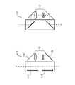
図2は、中間変倍光学系10の動作を説明する図である。台座11は、ミラー11a、11bを支持するとともに、レバー13に連結されている。モーター14がレバー13を移動させることにより台座11の位置が変更される。図2左のように対物レンズ16の光軸L上にミラー11a、11bが配置されるように台座11の位置を変更することで、光がレンズ群12を介して共焦点ディスク5へ向かう。一方、図2右のように光軸L上からミラー11a、11bが除外されるように台座11の位置を変更することで、光がレンズ群12を介さない。
FIG. 2 is a diagram illustrating the operation of the intermediate magnification
つまり、中間変倍光学系10のモーター14を駆動させることで、標本Sからの光がレンズ群12を介して共焦点ディスク5の表面上へ拡大投影されるか、レンズ群12を介さずに等倍で投影されるかが切り替わる。言い換えると、中間変倍光学系10は、共焦点ディスク5の表面上に形成する中間像の投影倍率が異なる2つの光学系を切り替えるように動作する。尚、2つの光学系の切り替えによっても光軸方向に結像位置が変化しないように投影される。
That is, by driving the
中間変倍光学系10は、レンズ群12を介して共焦点ディスク5の表面上へ投影される点像が、共焦点ディスク5の開口の2倍以上の大きさのエアリーディスク径を有するように設計される。例えば、レンズ群12を介さずに等倍で投影される際の点像と共焦点ディスク5の開口が同程度の大きさであるとしたとき、レンズ群12は少なくとも2倍以上の投影倍率を有するように設計することで、点像が開口の2倍の大きさとなる。
In the intermediate variable magnification
一般に、点像が投影される位置にある開口の直径をエアリーディスク径に対して十分に小さくする(望ましくはエアリーディスク径の1/2以下にする)ことで、その装置のカットオフ周波数を超える周波数成分(超解像成分)を含む光を得られることが知られている。従って、上述した中間変倍光学系10における構成では、台座11が光路上に設置されて光がレンズ群12を介するとき、超解像成分を含む光を撮像することができる。一方で、台座11が除外された場合に開口の大きさに対し1倍の大きさとなる点像を投影するため、光量損失を抑えつつ通常の共焦点観察を実行することができる。即ち、結像光学系30は、必要に応じて中間変倍光学系10を動作させることで超解像を得る観察と通常の観察とを切り替えて実行可能とする。
In general, the diameter of the opening at the position where the point image is projected is made sufficiently small with respect to the Airy disk diameter (preferably less than 1/2 of the Airy disk diameter) to exceed the cutoff frequency of the device. It is known that light containing a frequency component (super-resolution component) can be obtained. Therefore, in the configuration of the intermediate magnification
蛍光フィルタ17は、撮像対象となる蛍光以外の波長の光を遮断する。レンズ18は、標本Sからの光を撮像装置19へ結像する。撮像装置19は、共焦点ディスク5よりも標本Sから遠ざかる方向であり、対物レンズ16の焦点位置と共役な位置に配置される。
The
制御装置20は、結像光学系30を制御するためのコンピュータである。制御装置20は、例えば画像処理時に、接続された画像処理ボード32を使用することや、外付けの外部記憶装置33へデータを記録することを行ってもよい。
The
モニター31は、制御装置20から出力される画像を表示する。
The
図3は、制御装置20の機能構成を示す図である。制御装置20は、中間変倍制御部21、光源制御部22、露光制御部23、走査制御部24、画像処理部25を有している。
FIG. 3 is a diagram showing a functional configuration of the
中間変倍制御部21は、結像光学系30の中の中間変倍光学系10を制御する。より詳しくは、制御装置に接続されるキーボード等の入力装置からの使用者による入力に基づき、超解像観察を行う超解像観察モードと、通常観察を行う通常観察モードとを切り替え、切り替えたモードに応じて中間変倍光学系10内のモーター14を制御する。
The intermediate
超解像観察モードとは、超解像成分を含む画像を撮像し、後述する画像処理部25における画像処理を行い超解像成分が可視化された画像を得るための一制御モードである。つまり、中間変倍制御部21は、使用者から超解像観察モードを選択する入力を受け付けた場合、レンズ群12を光路上に配置するようにモーター14を制御する。
The super-resolution observation mode is a control mode for capturing an image containing a super-resolution component and performing image processing in the
通常観察モードとは、超解像成分を取得しない通常の観察を行う一制御モードである。使用者から通常観察モードを選択する入力を受け付けた場合、中間変倍制御部21は、レンズ群12を光路上から除外するようにモーター14を制御する。
The normal observation mode is a control mode for performing normal observation without acquiring super-resolution components. When an input for selecting a normal observation mode is received from the user, the intermediate
このように、中間変倍制御部21の機能を有するディスク走査型顕微鏡システム100によれば、観察モードの切り替えに応じて中間変倍光学系10の倍率が自動的に調節される。従って、使用者が中間変倍光学系10の倍率変更を行なう手間を省くことができ、使用者の負担を軽減したシステムを実現することができる。例えば、上記中間変倍光学系10の調節作業を手動で行う必要がある場合には、調整作業を忘れてしまう、または、誤って適切でない倍率に設定してしまうと、超解像成分を含む画像を得ることができず撮り直しを行う等、時間のロスが生じる。中間変倍制御部21を有する構成とすることで、このような人的ミスの発生についても未然に防止することができる。
As described above, according to the disk
光源制御部22は、光源ユニット1のON、OFF、及び、出力する照明光の強度(照明強度)の変更を制御する。また、光源制御部22は、光源ユニット1の照明強度を超解像観察モードと通常観察モードのそれぞれにおいて規定し、超解像観察モードと通常観察モードの切り替えに応じて、照明強度を規定された値に設定することが望ましい。例えば、超解像観察モードでは、中間像が開口の大きさを超える分の光量損失を考慮して照明強度が通常観察時よりも大きくなるように設定されるようにしても良い。
The light
露光制御部23は、撮像装置19の露光時間を制御する。また、露光制御部23は、撮像装置19の露光時間を超解像観察モードと通常観察モードのそれぞれにおいて規定し、超解像観察モードと通常観察モードの切り替えに応じて、露光時間を規定された値に設定することが望ましい。理由としては、光源制御部22と同様であり、超解像観察モード時における光量損失分を考慮し、超解像観察モードでは通常観察時よりも露光時間が長く設定するようにしても良い。
より具体的には、光源制御部22、露光制御部23は、通常観察モード及び超解像観察モードのそれぞれで規定の輝度値の画像が撮像装置19により撮像されるように、照明強度及び露光時間を規定しておくことが望ましい。
The
More specifically, the light
走査制御部24は、モーター6を制御することでマイクロレンズアレイディスク4、共焦点ディスク5を回転させ、標本S上での照明光の走査を行う。
The
画像処理部25は、超解像観察モード時に、撮像装置19が撮像した画像中の結像光学系30のカットオフ周波数を超える周波数成分を強調する処理を実行する。超解像観察モード時において、画像処理部25は、画像中の超解像成分を可視可能な状態とする。
The
図4は、制御装置20のハードウェア構成を示す。ハードウェア構成は、CPU51、DRAM52、ROM53、記憶部54、入出力IF55を備えている。
FIG. 4 shows the hardware configuration of the
CPU51は、ROM53に格納される各種制御プログラムを読みこんで実行する。
The
DRAM52は、制御プログラムや各種データを一時的に格納するワーキングエリアを提供する。ROM53は、各種制御プログラムを不揮発的に記憶する記憶媒体である。
The
記憶部54は、プログラムや画像データを格納し、フラッシュメモリやハードディスク等により構成される。入出力IF55は、ハードウェア外部とデータの送受信を行うものである。尚、各構成は、バス56により接続される。
The
図5は、標本Sの撮像時に制御装置20が実行するディスク走査型顕微鏡システム100の制御のフローチャートを示す。以下、図5で示すフローチャートについて説明する。
FIG. 5 shows a flowchart of control of the disk
ステップS1では、制御装置20は、使用者からの観察モードを設定する入力の有無を判定する。ステップS1で入力を検知した場合、制御装置20は、その入力に基づきステップS2において観察モードを設定する。ステップS2で通常観察モードが設定された場合、ステップS3へ移行し、ステップS2で超解像観察モードが設定された場合、ステップS4へ移行する。また、ステップS1で入力がない場合(もしくは観察モードの設定を行わない旨の入力を検知した場合)には、ステップS5へ移行する。
In step S1, the
尚、図5のフローチャートを開始するにあたり、制御装置20は予めデフォルトの観察モードを設定している。例えば、予め通常観察モードが設定されており、ステップS1で観察モードの入力が無い場合には通常観察モードが維持される。
In starting the flowchart of FIG. 5, the
ステップS3では、中間変倍制御部21が、中間像の投影倍率が1倍となるように中間変倍光学系10(モーター14)を制御する。具体的には、中間変倍制御部21は、モーター14を制御することで、結像光学系30の光路上からレンズ群12を除外する。
In step S3, the intermediate
ステップS4では、中間変倍制御部21が、中間像の投影倍率が2倍以上(レンズ群12で定められる投影倍率)となるように中間変倍光学系10(モーター14)を制御する。具体的には、中間変倍制御部21は、モーター14を制御することで、結像光学系30の光路上にレンズ群12が設置されるようにする。
In step S4, the intermediate
ステップS5では、制御装置20は撮像を実行するように制御を行う。具体的には、光源制御部22が設定された照明強度で照明光が照射されるように光源ユニット1を制御し、露光制御部23が設定された露光時間、露光を行うように撮像装置19を制御する。このとき、照明強度や露光時間は、上述したように光源制御部22、露光制御部23により観察モード毎に予め規定されており、現在の観察モードに合わせて制御装置20が制御を行うことが望ましい。ステップS5において撮像が終了した後、ステップS6へ移行する。
In step S5, the
ステップS6では、制御装置20は、現在の観察モードが超解像観察モードであるかどうかを判定する。超解像観察モードであるとき、ステップS7へ移行し、画像処理部25により超解像成分を強調する画像処理が実行される。
In step S6, the
ステップS6で超解像観察モードではないと判定されるか、ステップS7の超解像処理が終了するとステップS8へ移行する。ステップS8では、制御装置20は取得された画像データを、制御装置20内の記憶領域または外部記憶装置33に記憶し、処理を終了する。
When it is determined in step S6 that the mode is not the super-resolution observation mode, or when the super-resolution processing in step S7 is completed, the process proceeds to step S8. In step S8, the
以上のディスク走査型顕微鏡システム100によれば、超解像観察と通常観察とを切り替えて実行可能であるとともに、観察モードの切り替えに対して中間変倍光学系10の倍率が自動的に調節されるため、使用者が倍率変更を行う手間を省くことができる。また倍率変更に係る人的ミスが発生しないという観点からも従来と比較して効率的な観察を実現できる。
According to the above-mentioned disk
尚、超解像観察モード時に導光手段となるレンズ群12の投影倍率を通常観察時の2倍以上としたが、この構成に限定されるものではない。中間変倍光学系10は、超解像観察モード時に超解像成分を取得できるように、標本Sの照射位置の点像のエアリーディスク径が開口の直径の2倍以上となるように、レンズ群12の投影倍率が設定されていればよい。また、中間変倍光学系10は、通常観察モード時に明るさを確保できるように超解像観察モード時の中間像の投影倍率よりも低倍に設定されていればよい。また、中間変倍光学系10は、投影倍率が異なる2つ以上の光学系を有し、それらを切り替えるものであってもよい。
The projection magnification of the
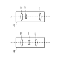
また、中間変倍光学系10は、光路を複数設けた図1、2で示される構成の他に、図6に示す構成であってもよい。図6は、変形例における中間変倍光学系110の構成を示す。中間変倍光学系110は、ミラー111、112、12a、12b、レンズ群12を含む。ミラー12a、12b、レンズ群12については、図2に示したものと同様である。ミラー111、112は、不図示のモーターに接続された可動式のミラーであり、一端を固定軸として回転移動する。動作例として、図6左、右に示すように回転を行う。
Further, the intermediate magnification
ディスク走査型顕微鏡システム100が中間変倍光学系110を有する場合、投影倍率の切り替えをミラー111、112の回転により実行する。中間変倍光学系110によれば、台座11を移動させるための駆動に係るエネルギーよりも少ないエネルギーにより投影倍率の切り替えが可能となる。また、構成の移動に伴う振動による影響が中間変倍光学系10と比較して小さい。
When the disk
また、中間変倍光学系10は、図7に示す構成であってもよい。図7は、変形例における中間変倍光学系120の構成を示す。中間変倍光学系120は、レンズ121、122、123を含む。レンズ121、レンズ122、レンズ123の少なくともいずれかはモーターにより光路上の位置が変更される。レンズ121からレンズ123は、全体としてズームレンズとして機能するため、特定の範囲における任意の投影倍率を設定することができ、システムとしての柔軟性が増す。
Further, the intermediate magnification
ディスク走査型顕微鏡システム100が中間変倍光学系120を有する場合、投影倍率の切り替えをレンズ122の移動により実行する。中間変倍光学系120によっても、台座11を移動させるよりも少ない駆動に係るエネルギーで投影倍率の切り替えが可能となる。また、ズームレンズの代わりに特定の投影倍率でのみ結像位置が保たれるバリフォーカルレンズを含む構成として、レンズ系を簡略化してもよい。
When the disk
上述した実施形態は、発明の理解を容易にするために具体例を示したものであり、本発明はこれらの実施形態に限定されるものではない。上述したディスク走査型顕微鏡システム、及びプログラムは、特許請求の範囲に記載した本発明を逸脱しない範囲において、さまざまな変形、変更が可能である。 The above-described embodiments show specific examples for facilitating the understanding of the invention, and the present invention is not limited to these embodiments. The above-mentioned disk scanning microscope system and program can be variously modified and modified without departing from the present invention described in the claims.
1 光源ユニット
2 光ファイバー
3 ビームエキスパンダ
4 マイクロレンズアレイディスク
5 共焦点ディスク
6、14 モーター
7 軸
8 ビームスプリッタ
10、110、120 中間変倍光学系
11 台座
11a、11b、12a、12b、111、112 ミラー
12 レンズ群
13 レバー
15、18、121、123 レンズ
16 対物レンズ
17 蛍光フィルタ
19 撮像装置
20 制御装置
21 中間変倍制御部
22 光源制御部
23 露光制御部
24 走査制御部
25 画像処理部
30 結像光学系30
31 モニター
32 画像処理ボード
33 外部記憶装置
40 共焦点ディスクユニット
51 CPU
52 DRAM
53 ROM
54 記憶部
55 入出力IF
56 バス
100 ディスク走査型顕微鏡システム
122 ズームレンズ
1
31
52 DRAM
53 ROM
54
56
Claims (9)
使用者からの入力に基づき、超解像観察を行う超解像観察モードと、通常観察を行う通常観察モードとを切り替え、切り替えたモードに応じて前記結像光学系を制御する制御装置と、
前記結像光学系の前側焦点位置と共役な位置に配置された、遮光部である表面上に複数の開口が形成され、回転するディスクと、を備え、
前記結像光学系は、前記ディスクに形成する前記観察物体上の位置の点像である中間像の投影倍率を変更する中間変倍光学系を含み、
前記制御装置は、
前記超解像観察モード時において前記中間像の投影倍率を、前記中間像が前記開口の2倍以上の大きさとなるように設定し、前記通常観察モード時において前記中間像の投影倍率を、前記超解像観察モード時の前記中間像の投影倍率よりも低倍に設定し、
前記中間像の投影倍率が、設定された前記投影倍率となるよう前記中間変倍光学系を制御する
ことを特徴とするディスク走査型顕微鏡システム。 An imaging optical system that takes in light from an observation object and forms an optical image of the observation object,
A control device that switches between a super-resolution observation mode for performing super-resolution observation and a normal observation mode for normal observation based on input from the user, and controls the imaging optical system according to the switched mode.
A disk having a plurality of openings formed on the surface of the light-shielding portion and rotating, which is arranged at a position conjugate with the front focal position of the imaging optical system, is provided .
The imaging optical system includes an intermediate magnification optical system that changes the projection magnification of an intermediate image that is a point image of a position on the observation object formed on the disk.
The control device is
In the super-resolution observation mode, the projection magnification of the intermediate image is set so that the intermediate image has a size of twice or more the aperture, and in the normal observation mode, the projection magnification of the intermediate image is set. Set to a lower magnification than the projection magnification of the intermediate image in the super-resolution observation mode.
The intermediate magnification optical system is controlled so that the projection magnification of the intermediate image becomes the set projection magnification.
A disk scanning microscope system characterized by this.
前記制御装置は、前記通常観察モード時において前記中間変倍光学系の投影倍率を、前記中間像が前記開口と同程度の大きさとなるように設定する
ことを特徴とするディスク走査型顕微鏡システム。 In the disk scanning microscope system according to claim 1,
The control device is a disk scanning microscope system characterized in that the projection magnification of the intermediate magnification optical system is set so that the intermediate image has the same size as the aperture in the normal observation mode.
前記ディスクよりも前記観察物体から遠ざかる方向であり、前記結像光学系の前側焦点位置と共役な位置に配置され、前記観察物体を撮像する撮像装置を備え、
前記制御装置は、前記超解像観察モード時に、前記撮像装置が撮像した画像中の前記結像光学系のカットオフ周波数を超える周波数成分を強調する処理を実行する
ことを特徴とするディスク走査型顕微鏡システム。 In the disk scanning microscope system according to claim 1 or 2.
It is provided with an image pickup device that is located farther from the observation object than the disk, is arranged at a position conjugate with the front focal position of the imaging optical system, and images the observation object.
The control device is a disk scanning type that performs a process of emphasizing a frequency component exceeding the cutoff frequency of the imaging optical system in an image captured by the imaging device in the super-resolution observation mode. Microscope system.
前記中間変倍光学系は、前記ディスクに形成する前記中間像の投影倍率が異なる2つ以上の光学系を切り替える
ことを特徴とするディスク走査型顕微鏡システム。 In the disk scanning microscope system according to any one of claims 1 to 3.
The intermediate magnification optical system is a disk scanning microscope system characterized in that two or more optical systems having different projection magnifications of the intermediate image formed on the disk are switched.
前記中間変倍光学系は、ズームレンズを含む
ことを特徴とするディスク走査型顕微鏡システム。 In the disk scanning microscope system according to any one of claims 1 to 3.
The intermediate magnification optical system is a disk scanning microscope system including a zoom lens.
前記観察物体を照明する光源ユニットを備え、
前記制御装置は、前記光源ユニットの照明強度、前記撮像装置の露光時間を、前記通常観察モードと前記超解像観察モードのそれぞれにおいて規定し、前記通常観察モードと前記超解像観察モードの切り替えに応じて、前記光源ユニットの照明強度、前記撮像装置の露光時間を規定された露光時間、照明強度に設定する
ことを特徴とするディスク走査型顕微鏡システム。 In the disk scanning microscope system according to claim 3,
A light source unit for illuminating the observation object is provided.
The control device defines the illumination intensity of the light source unit and the exposure time of the image pickup device in each of the normal observation mode and the super-resolution observation mode, and switches between the normal observation mode and the super-resolution observation mode. A disk scanning microscope system characterized in that the illumination intensity of the light source unit and the exposure time of the image pickup apparatus are set to a specified exposure time and illumination intensity according to the above.
前記制御装置は、前記通常観察モード及び前記超解像観察モードのそれぞれで規定の輝度値の画像が前記撮像装置により撮像されるように前記光源ユニットの照明強度、前記撮像装置の露光時間を、前記通常観察モードと前記超解像観察モードのそれぞれにおいて規
定する
ことを特徴とするディスク走査型顕微鏡システム。 In the disk scanning microscope system according to claim 6,
The control device determines the illumination intensity of the light source unit and the exposure time of the image pickup device so that an image having a predetermined luminance value in each of the normal observation mode and the super-resolution observation mode is captured by the image pickup device. A disk scanning microscope system, characterized in that it is defined in each of the normal observation mode and the super-resolution observation mode.
前記制御装置は、The control device is
前記通常観察モードへの切替を指示する入力を受け付けた場合、前記中間変倍光学系に含まれる1つ以上のレンズを光路上から除外するよう制御し、When an input instructing switching to the normal observation mode is received, control is performed so that one or more lenses included in the intermediate magnification optical system are excluded from the optical path.
前記超解像観察モードへの切替を指示する入力を受け付けた場合、前記中間変倍光学系に含まれる前記1つ以上のレンズを光路上に配置するよう制御するWhen an input instructing switching to the super-resolution observation mode is received, the control is performed so that the one or more lenses included in the intermediate magnification optical system are arranged on the optical path.
ことを特徴とするディスク走査型顕微鏡システム。A disk scanning microscope system characterized by this.
使用者からの入力に基づき、超解像観察を行う超解像観察モードと、通常観察を行う通常観察モードとを切り替え、切り替えたモードに応じて前記結像光学系を制御し、
前記超解像観察モード時において前記中間像の投影倍率を、前記中間像が前記開口の2倍以上の大きさとなるように設定し、前記通常観察モード時において前記中間像の投影倍率を、前記超解像観察モード時の前記中間像の投影倍率よりも低倍に設定し、
前記中間像の投影倍率が、設定された前記投影倍率となるよう前記中間変倍光学系を制御する
処理を実行させる
ことを特徴とするプログラム。 A plurality of imaging optics that take in light from an observing object and form an optical image of the observing object, and a plurality of light-shielding portions arranged at positions conjugate with the front focal position of the imaging optics. The imaging optical system comprises a rotating disk having an opening formed therein, and the imaging optical system includes an intermediate magnification optical system that changes the projection magnification of an intermediate image which is a point image of a position on the observation object formed on the disk. For the control device that controls the disk scanning microscope
Based on the input from the user, the super-resolution observation mode for performing super-resolution observation and the normal observation mode for performing normal observation are switched, and the imaging optical system is controlled according to the switched mode.
In the super-resolution observation mode, the projection magnification of the intermediate image is set so that the intermediate image has a size of twice or more the aperture, and in the normal observation mode, the projection magnification of the intermediate image is set. Set it to a lower magnification than the projection magnification of the intermediate image in the super-resolution observation mode.
The intermediate magnification optical system is controlled so that the projection magnification of the intermediate image becomes the set projection magnification.
A program characterized by executing processing.
Priority Applications (3)
| Application Number | Priority Date | Filing Date | Title |
|---|---|---|---|
| JP2017243442A JP7082482B2 (en) | 2017-12-20 | 2017-12-20 | Disc scanning microscope system, program |
| US16/221,575 US11280989B2 (en) | 2017-12-20 | 2018-12-16 | Disk scanning microscope system and computer-readable recording medium |
| EP18212929.6A EP3508902B1 (en) | 2017-12-20 | 2018-12-17 | Disc scanning microscope system and program |
Applications Claiming Priority (1)
| Application Number | Priority Date | Filing Date | Title |
|---|---|---|---|
| JP2017243442A JP7082482B2 (en) | 2017-12-20 | 2017-12-20 | Disc scanning microscope system, program |
Publications (2)
| Publication Number | Publication Date |
|---|---|
| JP2019109406A JP2019109406A (en) | 2019-07-04 |
| JP7082482B2 true JP7082482B2 (en) | 2022-06-08 |
Family
ID=64744372
Family Applications (1)
| Application Number | Title | Priority Date | Filing Date |
|---|---|---|---|
| JP2017243442A Active JP7082482B2 (en) | 2017-12-20 | 2017-12-20 | Disc scanning microscope system, program |
Country Status (3)
| Country | Link |
|---|---|
| US (1) | US11280989B2 (en) |
| EP (1) | EP3508902B1 (en) |
| JP (1) | JP7082482B2 (en) |
Families Citing this family (2)
| Publication number | Priority date | Publication date | Assignee | Title |
|---|---|---|---|---|
| GB2599651A (en) * | 2020-10-06 | 2022-04-13 | Andor Tech Limited | Confocal Raman analysing apparatus and method |
| DE102022108448B3 (en) * | 2022-04-07 | 2023-05-04 | Till I.D. Gmbh | Super-resolution rotating disk microscope apparatus |
Citations (4)
| Publication number | Priority date | Publication date | Assignee | Title |
|---|---|---|---|---|
| JP2003084209A (en) | 2001-07-27 | 2003-03-19 | Leica Microsystems Wetzlar Gmbh | Apparatus for micromanipulation of biological specimens |
| JP2003233010A (en) | 2002-02-08 | 2003-08-22 | Nikon Corp | Variable power optical device |
| JP2015079153A (en) | 2013-10-17 | 2015-04-23 | オリンパス株式会社 | Microscope system and disc unit |
| JP2016167080A (en) | 2000-05-03 | 2016-09-15 | ライカ バイオシステムズ イメージング インコーポレイテッドAperio Technologies, Inc. | Fully automatic rapid microscope slide scanner |
Family Cites Families (3)
| Publication number | Priority date | Publication date | Assignee | Title |
|---|---|---|---|---|
| JP3670745B2 (en) * | 1996-02-20 | 2005-07-13 | オリンパス株式会社 | Confocal microscope |
| JP5412394B2 (en) * | 2010-09-30 | 2014-02-12 | オリンパス株式会社 | Sample observation equipment |
| JP6253395B2 (en) * | 2013-12-19 | 2017-12-27 | オリンパス株式会社 | Image generation system |
-
2017
- 2017-12-20 JP JP2017243442A patent/JP7082482B2/en active Active
-
2018
- 2018-12-16 US US16/221,575 patent/US11280989B2/en active Active
- 2018-12-17 EP EP18212929.6A patent/EP3508902B1/en active Active
Patent Citations (4)
| Publication number | Priority date | Publication date | Assignee | Title |
|---|---|---|---|---|
| JP2016167080A (en) | 2000-05-03 | 2016-09-15 | ライカ バイオシステムズ イメージング インコーポレイテッドAperio Technologies, Inc. | Fully automatic rapid microscope slide scanner |
| JP2003084209A (en) | 2001-07-27 | 2003-03-19 | Leica Microsystems Wetzlar Gmbh | Apparatus for micromanipulation of biological specimens |
| JP2003233010A (en) | 2002-02-08 | 2003-08-22 | Nikon Corp | Variable power optical device |
| JP2015079153A (en) | 2013-10-17 | 2015-04-23 | オリンパス株式会社 | Microscope system and disc unit |
Also Published As
| Publication number | Publication date |
|---|---|
| JP2019109406A (en) | 2019-07-04 |
| US20190187447A1 (en) | 2019-06-20 |
| US11280989B2 (en) | 2022-03-22 |
| EP3508902B1 (en) | 2020-09-30 |
| EP3508902A1 (en) | 2019-07-10 |
Similar Documents
| Publication | Publication Date | Title |
|---|---|---|
| JP5863357B2 (en) | Magnification observation apparatus, and image display method and spectroscopic method switching method of magnification observation apparatus | |
| US7304790B2 (en) | Examination apparatus and focusing method of examination apparatus | |
| JP2007233098A (en) | Image acquisition device, image acquisition method, and image acquisition program | |
| JP2007024758A (en) | Optical inspection device and its illumination method | |
| JP7082482B2 (en) | Disc scanning microscope system, program | |
| JP6327829B2 (en) | Microscope control apparatus, microscope system, control method, and program | |
| JP2006171024A (en) | Multi-point fluorescence spectrophotometry microscope and multi-point fluorescence spectrophotometry method | |
| JP2009056507A (en) | Laser machining apparatus | |
| US20170351074A1 (en) | Laser scanning microscope, and laser scanning microscope control method | |
| JP6253509B2 (en) | Image display method, control device, microscope system | |
| JP5084183B2 (en) | Epi-illumination optical system for microscope | |
| JP2007163982A (en) | Microscope | |
| JP5019279B2 (en) | Confocal microscope and method for generating focused color image | |
| JP7134727B2 (en) | disk scanning microscope | |
| JP4112257B2 (en) | Confocal microscope | |
| JP2010020206A (en) | Microscope apparatus | |
| JP2009063679A (en) | Microscope system | |
| JP6062028B2 (en) | Magnification observation apparatus and magnification observation method | |
| JP6486713B2 (en) | Magnifying observation apparatus, setting method of magnifying observation apparatus, and program | |
| JP6962714B2 (en) | Observation device | |
| JP5278489B2 (en) | Microscope, microscope focus control method | |
| JP2007047754A (en) | Laser scanning microscope and image-acquiring method of the laser scanning microscope | |
| JP2004185005A (en) | Transmitted light illumination unit of microscope | |
| JP2003185936A (en) | Microscope system | |
| JP6378869B2 (en) | Microscope, microscope system, control method and program |
Legal Events
| Date | Code | Title | Description |
|---|---|---|---|
| RD03 | Notification of appointment of power of attorney |
Free format text: JAPANESE INTERMEDIATE CODE: A7423 Effective date: 20200717 |
|
| A621 | Written request for application examination |
Free format text: JAPANESE INTERMEDIATE CODE: A621 Effective date: 20201204 |
|
| A977 | Report on retrieval |
Free format text: JAPANESE INTERMEDIATE CODE: A971007 Effective date: 20211122 |
|
| A131 | Notification of reasons for refusal |
Free format text: JAPANESE INTERMEDIATE CODE: A131 Effective date: 20211130 |
|
| A521 | Request for written amendment filed |
Free format text: JAPANESE INTERMEDIATE CODE: A523 Effective date: 20220127 |
|
| TRDD | Decision of grant or rejection written | ||
| A01 | Written decision to grant a patent or to grant a registration (utility model) |
Free format text: JAPANESE INTERMEDIATE CODE: A01 Effective date: 20220524 |
|
| A61 | First payment of annual fees (during grant procedure) |
Free format text: JAPANESE INTERMEDIATE CODE: A61 Effective date: 20220527 |
|
| R151 | Written notification of patent or utility model registration |
Ref document number: 7082482 Country of ref document: JP Free format text: JAPANESE INTERMEDIATE CODE: R151 |
|
| S111 | Request for change of ownership or part of ownership |
Free format text: JAPANESE INTERMEDIATE CODE: R313113 |
|
| R350 | Written notification of registration of transfer |
Free format text: JAPANESE INTERMEDIATE CODE: R350 |