JP7080484B2 - Pachinko machine - Google Patents
Pachinko machine Download PDFInfo
- Publication number
- JP7080484B2 JP7080484B2 JP2018145420A JP2018145420A JP7080484B2 JP 7080484 B2 JP7080484 B2 JP 7080484B2 JP 2018145420 A JP2018145420 A JP 2018145420A JP 2018145420 A JP2018145420 A JP 2018145420A JP 7080484 B2 JP7080484 B2 JP 7080484B2
- Authority
- JP
- Japan
- Prior art keywords
- game
- control device
- symbol
- ball
- determination
- Prior art date
- Legal status (The legal status is an assumption and is not a legal conclusion. Google has not performed a legal analysis and makes no representation as to the accuracy of the status listed.)
- Active
Links
Images


Landscapes
- Pinball Game Machines (AREA)
Description
本発明は、遊技履歴に基づく性能の表示を行う遊技機に関するものである。 The present invention relates to a gaming machine that displays performance based on a gaming history.
パチンコ機等の従来の遊技機は、遊技領域に複数個の入賞口を備え、遊技者の操作に応じて発射された遊技球が入賞口に入球することで賞球が発生する。近年では、このような入賞口への入球数に基づいて獲得した賞球数等の遊技履歴となる遊技性能(大当り以外の出玉率、役物に係る出玉率等)を遊技機毎に確認したいという要望があり、遊技機毎に該遊技性能を確認可能とする発明がある<特許文献1>。また、表示する遊技性能を算出する場合、総発射遊技球数を遊技球の発射に基づいて計数する必要があるが、封入式の弾球遊技機であれば、発射球数の計数機能を備えているためその値を流用して算出できるが、遊技球を機外に排出する弾球遊技機の場合、遊技領域最下部のアウト口に入球した遊技球を含め遊技領域から排出された全ての遊技球(遊技領域に発射された遊技球)を計数する検出装置(所謂、アウトセンサ)を備える必要がある。
A conventional gaming machine such as a pachinko machine is provided with a plurality of winning openings in a gaming area, and a winning ball is generated when a gaming ball launched in response to a player's operation enters the winning opening. In recent years, the game performance (the ball ejection rate other than the big hit, the ball ejection rate related to the character, etc.), which is the game history such as the number of prize balls acquired based on the number of balls entered into the winning opening, has been determined for each gaming machine. There is an invention that makes it possible to confirm the gaming performance for each gaming machine <
上記した遊技性能の表示は、今後開発されるパチンコ遊技機には標準装備となるが、その場合、パチンコ遊技機が製造されて最初の通電からアウト数(発射球数)が所定数(現状では300)に達するまでは性能表示となる遊技履歴の表示を行わないものとなる。これは、すぐに性能表示を開始してしまうと、実際の設置ホールにおける遊技開始時に表示される内容は、出荷時及びホール設置時の検査で検出した遊技球に基づく値であり、このような性能と無関係の数値を表示するのを避けるため、等の理由からとなる。 The above-mentioned display of gaming performance will be standard equipment on pachinko gaming machines to be developed in the future, but in that case, the number of outs (number of launching balls) from the first energization of the pachinko gaming machine will be a predetermined number (currently). Until it reaches 300), the game history, which is the performance display, is not displayed. This is because if the performance display is started immediately, the content displayed at the start of the game in the actual installation hall is a value based on the game ball detected by the inspection at the time of shipment and at the time of installation of the hall. This is for reasons such as to avoid displaying numerical values unrelated to performance.
しかしながら、最初の通電後アウトセンサが所定数の遊技球を検出してからでないと性能表示が行われないようにすると、アウトセンサの検出結果を唯一表示するのが性能表示であるため、遊技機製造メーカーにおける出荷時の動作確認検査、及びホール設置時の確認検査において、アウトセンサが正常に遊技球を検出しているか否かの検査が好適に行えないという問題が発生する。 However, if the performance display is not performed until the out sensor detects a predetermined number of game balls after the first energization, the performance display is the only display of the detection result of the out sensor. In the operation confirmation inspection at the time of shipment by the manufacturer and the confirmation inspection at the time of installing the hall, there arises a problem that it is not possible to appropriately inspect whether or not the out sensor normally detects the game ball.
詳しくは、遊技領域に配設された入賞口への入球を検出する検出センサの検査は、入賞口に入球した遊技球を検出すると所定の図柄が変動を行ったり賞球が発生するため、図柄変動又は賞球の有無で行えるが、遊技領域から排出される遊技球を検出するアウトスイッチ(アウトセンサともいう)は、遊技領域に発射された遊技球を計数するために配設されているため、遊技球を検出しても目に見える動作は行われず、アウトスイッチの遊技球検出に応じた性能表示の変化が行われなければ、正常に遊技球を検出しているかどうかが確認できない。従って、パチンコ遊技機の動作仕様の範囲でアウトスイッチの検出確認を行うためには、所定数の遊技球をアウトセンサに検出させなければならないが、現状では所定数として300が決まっているため、検査時の手間が極めて大きくなってしまう。 Specifically, the inspection of the detection sensor that detects the entry into the winning opening arranged in the game area is because when the gaming ball that has entered the winning opening is detected, the predetermined symbol fluctuates or the winning ball is generated. An out switch (also called an out sensor) that detects a game ball ejected from the game area is arranged to count the game balls fired in the game area. Therefore, even if the game ball is detected, no visible operation is performed, and unless the performance display is changed according to the game ball detection of the out switch, it cannot be confirmed whether or not the game ball is detected normally. .. Therefore, in order to confirm the detection of the out switch within the operating specifications of the pachinko gaming machine, it is necessary to have the out sensor detect a predetermined number of game balls, but at present, 300 is determined as the predetermined number. The time and effort required for inspection becomes extremely large.
そこで本願発明は、上記した問題を鑑み、遊技履歴に基づく遊技性能を表示する性能表示手段を設けた遊技機において、出荷時、及びホール設置時の動作確認が好適に行える弾球遊技機の提供を目的とする。 Therefore, in view of the above-mentioned problems, the present invention provides a ball-and-ball gaming machine that can suitably check the operation at the time of shipment and at the time of setting a hole in a gaming machine provided with a performance display means for displaying the gaming performance based on the gaming history. With the goal.
請求項1記載の弾球遊技機は、
賞球数が設定された複数の入賞口を遊技領域に配設し、
該遊技領域から排出された遊技球を検出するアウト検出手段と、
遊技により発生した各種情報を記憶する記憶手段と、
該記憶手段が記憶する前記各種情報に基く演算結果を表示する表示手段と、
前記遊技領域を有する遊技盤に対して開閉可能に支持されたガラス枠と、
前記アウト検出手段が遊技球を検出すると報知を行うアウト報知手段と、
を備えた弾球遊技機であって、
前記表示手段は、前記記憶手段が記憶する前記各種情報が所定の記憶量に達するまでは非表示状態を維持し、所定の記憶量に達すると表示状態とし、
前記アウト報知手段は、電源投入から所定条件が成立するまで前記報知を実施し、
前記所定条件が未成立でも前記ガラス枠を閉鎖すると前記報知を終了する
ことを特徴とする弾球遊技機である。
The ball gaming machine according to
Multiple winning openings with a set number of prize balls are arranged in the game area,
An out-detecting means for detecting a game ball discharged from the game area,
A storage means for storing various information generated by the game,
A display means for displaying calculation results based on the various information stored in the storage means , and a display means.
A glass frame that can be opened and closed with respect to the game board having the game area,
An out-notifying means that notifies when the out-detecting means detects a game ball, and an out-notifying means.
It is a bullet game machine equipped with
The display means maintains a non-display state until the various information stored by the storage means reaches a predetermined storage amount, and sets the display state when the predetermined storage amount is reached.
The out notification means performs the notification from turning on the power until a predetermined condition is satisfied .
Even if the predetermined condition is not satisfied, the notification is terminated when the glass frame is closed.
It is a ball game machine characterized by this.
遊技領域に配設された複数の入賞口においては、各入賞口への遊技球の入賞を検出する入賞検出手段を設けるのが望ましい。遊技領域から排出された遊技球を検出するアウト検出手段は、遊技領域を転動した全ての遊技球、言い換えれば、遊技領域に発射された全ての遊技球を検出可能な検出手段となる。従って、遊技球が入賞口に入賞すると、各入賞口に対して配設された入賞センサ(入賞検出手段)が当該入賞口への入賞を検出し、当該検出された遊技球は再度アウトセンサに検出される構成となる。また、いずれの入賞口にも入賞せず、アウト口(主に遊技領域最下部に配設)へ入球した遊技球もアウトセンサ(アウト検出手段)には検出される。これにより、アウトセンサの検出数が遊技領域から排出された(遊技領域に発射された)遊技球の総数となる。なお、アウト検出手段となるアウトセンサは、遊技の進行を制御する主制御装置に接続される構成が好適であるが、払出制御装置に接続して遊技球検出信号を主制御装置に送信する構成も考えられる。 In a plurality of winning openings arranged in the game area, it is desirable to provide a winning detection means for detecting the winning of the game ball in each winning opening. The out-detecting means for detecting the game balls discharged from the game area is a detection means capable of detecting all the game balls that have rolled in the game area, in other words, all the game balls launched into the game area. Therefore, when the game ball wins in the winning opening, the winning sensor (winning detecting means) arranged for each winning opening detects the winning in the winning opening, and the detected game ball becomes the out sensor again. It will be detected. Further, a game ball that has not won a prize in any of the winning openings and has entered the out opening (mainly arranged at the bottom of the game area) is also detected by the out sensor (out detecting means). As a result, the number of detected out-sensors is the total number of game balls ejected from the game area (launched into the game area). The out sensor serving as the out detection means is preferably connected to the main control device that controls the progress of the game, but is connected to the payout control device to transmit the game ball detection signal to the main control device. Is also possible.
また、アウト検出手段の異なる検出構成として、アウトセンサが遊技領域最下部のアウト口に入球した遊技球のみ検出する構成であったなら、遊技領域に発射された遊技球の総数は、全ての入賞センサ(入賞検出手段)が検出した遊技球数にアウトセンサ(アウト口に入球した遊技球のみ)の検出した遊技球数を加算した数が、遊技領域から排出された遊技球の総数となる。 Further, if the out sensor has a configuration in which only the game balls that have entered the out port at the bottom of the game area are detected as different detection configurations of the out detection means, the total number of game balls fired in the game area is all. The total number of game balls ejected from the game area is the sum of the number of game balls detected by the prize sensor (winning detection means) and the number of game balls detected by the out sensor (only the game balls that have entered the out port). Become.
遊技により発生した各種情報を収集して記憶し、該記憶内容に基いて遊技履歴を表示する性能表示手段による表示は、遊技の進行を制御する主制御装置が直接制御し、表示する内容も主制御装置に接続された各入賞口の入賞を検出する検出センサ(入賞検出手段)の検出に基づいて発生した賞球数と、発射球数となるアウト検出手段の検出数と(遊技により発生した各種情報)に基づいて、主制御装置が算出する構成が好適である。また、遊技履歴を表示する表示器は、遊技盤裏面の主制御装置の背面等、主制御装置上(主基板上)に配置され、遊技中の遊技者からは視認不可な位置への配設が好適である。 The display by the performance display means that collects and stores various information generated by the game and displays the game history based on the stored contents is directly controlled by the main control device that controls the progress of the game, and the contents to be displayed are also the main. The number of prize balls generated based on the detection of the detection sensor (winning detection means) that detects the winning of each winning opening connected to the control device, and the number of detections of the out detecting means which is the number of launched balls (generated by the game). A configuration calculated by the main controller based on various information) is preferable. In addition, the display for displaying the game history is arranged on the main control device (on the main board) such as the back of the main control device on the back surface of the game board, and is arranged at a position invisible to the player during the game. Is preferable.
また、「記憶内容が所定の記憶量に達するまでは」の、記憶内容は、遊技の進行に伴って遊技領域から排出された遊技球の数や所定の入賞口へ入賞した遊技球の数等としてもよく、所定の記憶量に達するまでとは、これらの数が遊技の進行に伴って所定の数に達することとしてもよい。 In addition, the stored content of "until the stored content reaches a predetermined storage amount" includes the number of game balls discharged from the game area as the game progresses, the number of game balls won in the predetermined winning opening, and the like. However, until a predetermined amount of memory is reached, these numbers may reach a predetermined number as the game progresses.
遊技により発生した各種情報を収集して記憶し、該記憶内容に基いて表示する遊技履歴(遊技性能)は、パチンコ遊技機であれば、遊技領域に発射された遊技球数や、入賞口毎の賞球数とに基づく演算結果を表示してもよく、具体的には、総賞球数を総発射球数で除算することで算出した「出玉率」、大当り遊技状態及び時短状態(開放延長状態)を除く、所謂、通常遊技状態で獲得した賞球数を通常遊技状態の発射球数で除算することで算出する「ベース」、大入賞口と普通電動役物への入球による賞球数を全ての賞球数で除算することで算出した「役物比率」、大入賞口への入球による賞球数を全ての賞球数で除算することで算出した「連続役物比率」、等としてもよい。 If it is a pachinko game machine, the game history (game performance) that collects and stores various information generated by the game and displays it based on the stored contents is the number of game balls fired in the game area and each winning opening. The calculation result based on the number of prize balls may be displayed. Specifically, the "ball output rate" calculated by dividing the total number of prize balls by the total number of fired balls, the jackpot game state, and the time saving state ( Except for the open extension state), the so-called "base" calculated by dividing the number of prize balls acquired in the normal game state by the number of fired balls in the normal game state, by entering the large winning opening and the ordinary electric accessory The "feature ratio" calculated by dividing the number of prize balls by all the prize balls, and the "continuous bonus" calculated by dividing the number of prize balls by entering the large winning opening by all the prize balls. It may be "ratio", etc.
遊技履歴(遊技性能)を演算するために必要な記憶内容は、電源を落としても、RAMクリア操作を行っても消去されない構成としてもよく、これにより遊技機の店舗導入からの長期間データを基に収束した遊技性能を表示することができる。遊技機への最初の通電により各種情報の収集と記憶を開始すると、その後は電源を落としてもRAMクリアを行っても、記憶内容は蓄積されていく。従って、性能表示手段が遊技履歴を非表示とするのは、パチンコ遊技機の製造後、ホールに設置されて遊技に伴う記憶内容が記憶量に達するまでの期間のみとなり、主に遊技機製造メーカーにおける出荷検査時とホール設置時の検査において、遊技履歴は未だ非表示の状態となる。なお、電源を落とすことにより遊技履歴データが消去される構成としてもよい。 The stored content required to calculate the game history (game performance) may be configured so that it will not be erased even if the power is turned off or the RAM is cleared, which allows long-term data from the introduction of the game machine to the store. It is possible to display the game performance that has converged based on the basis. When the collection and storage of various information is started by the first energization of the gaming machine, the stored contents are accumulated even if the power is turned off or the RAM is cleared. Therefore, the performance display means hides the game history only during the period from the manufacture of the pachinko gaming machine to the time when the pachinko gaming machine is installed in the hall and the stored contents of the game reach the storage amount. The game history is still hidden during the shipping inspection and the inspection at the time of setting up the hall. The game history data may be deleted by turning off the power.
アウト検出手段が、遊技領域最下部のアウト口に入球した遊技球を含む遊技領域から排出された遊技球(遊技領域に発射された遊技球)を検出すると、主制御装置から演出機器を制御するサブ制御装置にコマンドを送信する構成としてもよい。この場合、遊技機への最初の通電から所定期間中に行われるRAMクリアに限り、アウト検出手段の遊技球検出に応じてサブ制御装置に当該検出を示すコマンドを送信する構成としてもよく、このコマンドを送信可能とする期間はサブ制御装置がRAMクリアの実施を報知するRAMクリア報知が終了するまでの期間としてもよい。また、RAMクリア報知期間は、該RAMクリア報知を実施する各種演出機器(発光部材、スピーカ)等の動作により、パチンコ遊技機が備える各種センサ(特に遊技盤に配設されたセンサ)、及び各種演出機器(発光部材、スピーカ)の動作確認を実施可能する期間としてもよい。 When the out detection means detects a game ball (a game ball launched into the game area) discharged from the game area including the game ball that has entered the out port at the bottom of the game area, the main control device controls the effect device. It may be configured to send a command to the sub-control device. In this case, as long as the RAM is cleared during a predetermined period from the first energization of the gaming machine, a command indicating the detection may be transmitted to the sub control device in response to the gaming ball detection of the out detecting means. The period during which the command can be transmitted may be the period until the RAM clear notification for notifying the execution of the RAM clear by the sub control device is completed. In addition, during the RAM clear notification period, various sensors (particularly sensors arranged on the gaming board) provided in the pachinko gaming machine and various types are operated by the operation of various effect devices (light emitting members, speakers) that perform the RAM clear notification. It may be a period during which the operation of the staging device (light emitting member, speaker) can be confirmed.
また、遊技盤の前面には、主制御装置から受信するコマンドに基づいてサブ制御装置が表示制御する遊技の進行状態を報知する演出表示装置が配置されるが、同様に、主制御装置自体が遊技の進行状態を表示制御する状態表示装置を遊技盤の前面に配置する構成が好適である。この状態表示装置には、例えば、遊技領域に配設された入賞口である始動口への入賞に起因する抽選の結果を導出表示する図柄の表示や、該抽選を待機する保留記憶数を表示する。 Further, on the front surface of the game board, an effect display device for notifying the progress state of the game, which is displayed and controlled by the sub control device based on the command received from the main control device, is arranged. Similarly, the main control device itself It is preferable to arrange the state display device for displaying and controlling the progress state of the game on the front surface of the game board. In this status display device, for example, a symbol for deriving and displaying the result of a lottery caused by winning a prize in a starting slot, which is a winning slot arranged in a game area, and a number of pending storages waiting for the lottery are displayed. do.
請求項1記載の遊技機によれば、遊技により発生した各種情報の記憶内容に基いて遊技履歴を表示する弾球遊技機において、アウト検出手段の検出結果を唯一表示する遊技履歴が非表示であってもアウト検出が正常か否かのチェックが可能となり、出荷時、及びホール設置時の動作確認を好適に行うことができる。
According to the gaming machine according to
以下、本発明の実施形態について図面を用いて説明する。尚、本発明の実施の形態は、下記の実施形態に何ら限定されることはなく、本発明の技術的範囲に属する限り種々の形態を採りうる。 Hereinafter, embodiments of the present invention will be described with reference to the drawings. The embodiments of the present invention are not limited to the following embodiments, and various embodiments may be adopted as long as they belong to the technical scope of the present invention.
図1に示すパチンコ機50は、縦長の固定外郭保持枠をなす外枠51にて構成の各部を保持する構造である。外枠51の左側上下には、ヒンジ53が設けられており、該ヒンジ53の他方側には図3に記載する内枠70が取り付けられており、内枠70は外枠51に対して開閉可能な構成になっている。ガラス枠52には、板ガラス61が取り外し自在に設けられており、板ガラス61の奥には図2に記載する遊技盤1が内枠70に取り付けられている。
The
ガラス枠52の上側左右には、スピーカ66が設けられており、パチンコ機50から発生する遊技音が出力され、遊技者の趣向性を向上させる。また、遊技者の趣向性を向上させるためにガラス枠52に遊技状態に応じて発光する装飾発光体65も複数設けられている。ガラス枠52の下方には、上皿55と下皿63が一体に形成されている。下皿63の右側には発射ハンドル64が取り付けられており、該発射ハンドル64を時計回りに回動操作することによってハンドルボリューム130(図6参照)が回動量を検出し発射装置(図示省略)が可動して、上皿55から供給された遊技球が遊技盤1に向けて発射される。発射ハンドル64には、該発射ハンドル64への接触を検知するタッチスイッチ28(図示省略、図6参照)と、発射を停止する発射停止スイッチ29とが配置されている。
上皿55の上部ほぼ中央には、遊技者が操作可能な演出ボタン67、及びジョグダイヤル68が備えられている。また、このパチンコ機50はいわゆるCR機であって、プリペイドカードの読み書き等を行うためのプリペイドカードユニット(CRユニット)56が付属しており、パチンコ機50には、貸出ボタン57、精算ボタン58及び残高表示器59を有するCR精算表示装置が備わっている。
An
図2は、本実施例のパチンコ機の遊技盤1の正面図である。図2に示すように遊技盤1には、公知のガイドレール2a、2bによって囲まれた略円形の遊技領域3が設けられている。この遊技領域3には多数の遊技釘4が打ち付けられている。遊技領域3のほぼ中央部には、センターケース5が配されている。センターケース5は、公知のものと同様に、ワープ入口、ワープ通路、ステージ、演出図柄表示装置6の画面を臨ませる窓等を備えている。センターケース5の下には、第1始動口11(本発明の入賞口に相当)と第2始動口12(本発明の入賞口に相当)とが配置され、センターケース5の左方には、普通図柄作動ゲート17が配置されている。第2始動口12は開閉可能な羽根部材を供えた普通電動役物を備えており、この羽根部材が開放しないと遊技球は第2始動口12に入球できない構成となっている。
FIG. 2 is a front view of the
第2始動口12の下方にはアタッカー式の大入賞口14(本発明の入賞口に相当)が配置されている。また、第1始動口11の左方には、4個の普通入賞口31、32、33、34(本発明の入賞口に相当)が設けられている。なお、この4個の普通入賞口は常時入球率が変化しない入賞口である。遊技領域3の最下部には、どの入賞口にも入賞しなかった遊技球を回収するアウト口100が配設されている。このアウト口100に入球した遊技球は、後述するアウトスイッチ100a(図6参照)に検出される。
An attacker-type large winning opening 14 (corresponding to the winning opening of the present invention) is arranged below the second starting opening 12. Further, four ordinary winning
上記のように遊技盤1を構成することによって、普通図柄作動ゲート17に遊技球が入球(普通図柄作動スイッチ17a(図6参照)が遊技球を検出)すると、普通図柄表示装置7で普通図柄が変動表示を開始し、所定時間後に停止した普通図柄の態様に応じて、後述する普通電役ソレノイド12b(図6参照)を駆動させる。普通電役ソレノイド12bを駆動させると、ほぼ同期して第2始動口12を構成する普通電動役物の羽根部材が駆動して、第2始動口12への入球(第2特別図柄始動スイッチ12a(図6参照)での遊技球検出)が可能となるように構成されている。
By configuring the
第1始動口11に遊技球が入球(第1特別図柄始動スイッチ11a(図6参照)が遊技球を検出)すると、第1特別図柄表示装置9において第1特別図柄が変動を開始し、所定時間後に停止する。また、第2始動口12(普通電動役物)に遊技球が入球(第2特別図柄始動スイッチ12a(図6参照)が遊技球を検出)すると、第2特別図柄表示装置10において第2特別図柄が変動表示を開始し、所定時間後に停止する。
When the game ball enters the first start port 11 (the first special
第1特別図柄及び第2特別図柄の変動中は、演出図柄表示装置6において各々の特別図柄の変動に連動した擬似図柄の演出態様を表示する。また、第1特別図柄と第2特別図柄は、第1始動口と第2始動口への入球順に関係なく、第2特別図柄の変動表示を優先して実施する。具体的には、第1特別図柄の保留記憶がある場合、第2特別図柄の変動が停止し且つ第2特別図柄保留記憶が無いことを条件として、第1特別図柄保留記憶分の変動を開始する。
During the change of the first special symbol and the second special symbol, the effect
第1特別図柄及び第2特別図柄の態様に応じて後述する大入賞口ソレノイド14b(図6参照)を駆動させる。大入賞口ソレノイド14bを駆動させると、ほぼ同期して大入賞口14の扉部材が駆動して、大入賞口14への入球(カウントスイッチ14a(図6参照)での検出)が可能となるように構成されている。
The large
遊技領域の右下部には、状態表示装置110が配置され、この状態表示装置110には、複数個のLEDからなる普通図柄表示装置7と、普通図柄保留数表示装置8と、第1特別図柄保留数表示装置18と、第2特別図柄保留数表示装置19と、7セグメントLED表示装置からなる第1特別図柄表示装置9、第2特別図柄表示装置10とが配置されている。
A
また、本実施例のパチンコ機50には、遊技領域を転動した後に該遊技領域から排出された全ての遊技球を検出するアウトスイッチ100aが配設されている。この場合のアウトスイッチ100aは遊技領域への発射球数を計数するセンサとなる。アウト口100への入球のみを検出するセンサを配置した場合の全ての発射球数は、全ての入賞口への入賞数とアウト口100への入球数とをの加算値となる。
Further, the
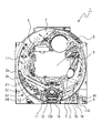
続いて、図3に本実施例におけるパチンコ機の裏面図を示し説明する。パチンコ機50の裏面は図3に示すとおり、前述した遊技盤1を脱着可能に取り付ける内枠70が前述した外枠51に収納されている。この内枠70には、上方から、球タンク71、タンクレール72及び払出装置73が設けられている。この構成により、遊技盤1上の入賞口に遊技球の入賞があれば球タンク71からタンクレール72を介して所定個数の遊技球を払出装置73により前述した上皿55に排出することができる。また、パチンコ機50の裏側には、主制御装置80、払出発射制御装置81、演出図柄制御装置82、サブ統合制御装置83、電源基板85が設けられている。なお、演出図柄制御装置82、サブ統合制御装置83が所謂サブ制御装置に相当する。
Subsequently, FIG. 3 shows and describes a back view of the pachinko machine in this embodiment. As shown in FIG. 3, the back surface of the
主制御装置80、演出図柄制御装置82、サブ統合制御装置83は遊技盤1に設けられており、払出発射制御装置81、電源基板85が内枠70に設けられている。球タンク71の右側には、外部接続端子78が設けられており、この外部接続端子78より、遊技状態や遊技結果を示す信号が図示しないホールコンピュータに送られる。なお、従来はホールコンピュータへ信号を送信するための外部接続端子78には、盤用(遊技盤側から出力される信号をホールコンピュータへ出力するための端子)と枠用(枠側(ガラス枠52、内枠70、外枠51)から出力される信号をホールコンピュータへ出力するための端子)の2種類を用いているが、本実施例では、一つの外部接続端子78を介してホールコンピュータへ遊技状態や遊技結果を示す信号を送信している。
The
また、パチンコ機50裏側に取り付けられた主制御装置80の背面には、結果表示装置91(本発明の記憶内容に基いて遊技履歴を表示する性能表示手段に相当)が設けられている。結果表示装置91には、3つの7セグメントLED表示装置が設けられており、左から第1表示装置91a、第2表示装置91b、第3表示装置91cとなっている(図5参照)。
Further, a result display device 91 (corresponding to a performance display means for displaying a game history based on the stored contents of the present invention) is provided on the back surface of the
図5に示すように、結果表示装置91では、第1表示装置91aにベース(通常遊技中の出玉率)、第2表示装置91bに役物比率(全賞球数に対する役物(大入賞口14と普通電動役物(第2始動口12))入球による賞球数の割合)、第3表示装置91cに連続役物比率(全賞球数に対する大入賞口14入球による賞球数の割合)の演算結果をそれぞれ表示する。なお、この結果表示装置91における演算結果(記憶内容に基づく遊技履歴)の表示は、パチンコ遊技機50への最初の通電後、アウトスイッチ100aが300個の遊技球を検出すると開始されるが、それまでは、演算結果の表示は行わず、待機態様(例えば、それぞれの7セグメントLEDの真ん中の横棒のみ表示してもよい「ーーー」)の表示を行う。
As shown in FIG. 5, in the
なお、主制御装置80には、主制御装置80のRAMに記憶された情報を消去するためにRAMクリアスイッチ97が設けられている。しかしながら、結果表示装置91に表示する演算に係る情報(最初の通電以降の各入賞口毎の賞球数、及びアウトスイッチ100aの検出数)は消去されない。また、RAMクリアに応じて行われるRAMクリア報知は、パチンコ機の動作確認が可能な動作発光態様を行うことが望ましい。なお、RAMクリアスイッチを払出発射制御装置81や電源基板85に設ける構成としてもよい。
The
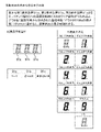
次に、図4の図表を用いて、第1表示装置91a~第3表示装置91cに表示される具体的な演算内容を説明する。第1表示装置91aに表示される通常時の出玉率である「ベース」値は、大当り遊技時と時短遊技時(普通電動役物の開放が頻繁に行われる遊技時)以外の出玉率となり、総賞球数から大当り遊技時の賞球数と時短遊技時の賞球数とを減算した値を、総発射遊技球数から大当り遊技時の発射球数と、時短遊技時の発射球数とを減算した値で除算して求める。このベース値が低いほど、遊技者の消費スピードが早くなる。
Next, specific calculation contents displayed on the
第2表示装置91bに表示される全ての役物への入賞に基づいて算出する「役物比率」値は、大入賞口14、及び第2始動口12である普通電動役物への入球に基づいて獲得した賞球数の総賞球数に対する割合となり、カウントスイッチ14aの検出に基づく賞球数と第2始動口スイッチ12aの検出に基づく賞球数との加算値を、総賞球数で除算して求める。
The "feature ratio" value calculated based on the winning of all the winnings displayed on the
第3表示装置91cに表示される大入賞口14のみの入賞に基づいて算出する「連続役物比率値」は、大入賞口14への入球に基づいて獲得した賞球数の総賞球数に対する割合となり、カウントスイッチ14aの検出に基づく賞球数を、総賞球数で除算して求める。
The "continuous bonus ratio value" calculated based on the winning of only the large winning
図5に示すように、第1表示装置91a~第3表示装置91cへの演算結果の表示方法は共通であり、具体的な表示内容は、消灯であればそれぞれの比率値が0%以上10%未満であることを、7セグメントLEDが「1」を表示すればそれぞれの比率値が10%以上20%未満であることを、同様に「2」を表示すればそれぞれの比率値が20%以上30%未満であることを、同様に「3」を表示すればそれぞれの比率値が30%以上40%未満であることを、以下、7セグメントLEDが「9」を表示するまで10%刻みの報知を行う。なお、所定数の入賞口への入賞を検出したにも拘わらず、アウトスイッチ100aが遊技球の検出を行わない場合は、結果表示装置91においてエラー表示を行う構成としてもよい。エラー表示は、例えば、小数点を示す右下のセグメントのみを点灯してもよし、アルファベットのEを示す態様を表示してもよい。
As shown in FIG. 5, the method of displaying the calculation result on the
続いて、図6に本実施例におけるパチンコ機の電気配線を示すブロック図を示し説明する。図4には煩雑になる電源の供給系統に関する記載は行わないが、電源が必要な制御装置若しくはアクチュエータ類には、電源装置(図示せず)から直接的又は間接的に供給される構成となっている。 Subsequently, FIG. 6 shows and describes a block diagram showing the electrical wiring of the pachinko machine in this embodiment. Although FIG. 4 does not describe the complicated power supply system, the control device or actuators that require power supply are directly or indirectly supplied from the power supply device (not shown). ing.
パチンコ機50の電気的構成は、ブロック図に示すとおり、主制御装置80を中心にして構成されている。なお、このブロック図には、単に信号を中継するだけのためのいわゆる中継基板及び電源回路等は記載していない。また、詳細の図示は省略するが、主制御装置80、払出発射制御装置81、演出図柄制御装置82、サブ統合制御装置83のいずれもCPU、ROM、RAM、入力ポート、出力ポート等を備えている。
As shown in the block diagram, the electrical configuration of the
主制御装置80には、第1始動口11に入球した遊技球を検出する第1始動口スイッチ11a、第2始動口12となる普通電動役物に入球した遊技球を検出する第2始動口スイッチ12a、普通図柄を作動させるゲート17に進入した遊技球を検出する普通図柄作動スイッチ17a、大入賞口14に入球した遊技球を計数するためのカウントスイッチ14a、普通入賞口31、32、33、34に入球した遊技球を検出する普通入賞口スイッチ31a、等の検出信号が遊技盤中継端子板74を介して入力される。
The
また、裏配線中継端子盤75を介してアウトスイッチ100aの検出信号が主制御装置に入力され、主制御装置80はこのアウトスイッチ100aが検出した値を遊技領域への発射球数として記憶する。
Further, the detection signal of the out switch 100a is input to the main control device via the back wiring
主制御装置80は搭載しているプログラムに従って動作して、上述の検出信号などに基づいて遊技の進行に関わる各種のコマンドを生成して払出発射制御装置81及びサブ統合制御装置83に出力する。また主制御装置80は、図柄表示装置中継端子板90を介して接続されている第1特別図柄表示装置9、第2特別図柄表示装置10及び普通図柄表示装置7の表示、第1特別図柄保留数表示装置18、第2特別図柄保留数表示装置19、普通図柄保留数表示装置8の点灯を直接制御する。
The
更に、主制御装置80は、大入賞口ソレノイド14bを制御することで大入賞口14の開閉を制御し、普通電動役物ソレノイド(普電役物ソレノイドと表記)12bを制御することで第2始動口12の開閉を制御する。主制御装置80からの出力信号は試験信号端子にも出力される他、図柄変動や大当り(特別遊技ともいう)等の管理用の信号が外部接続端子78に出力されてホールコンピュータに送られる。
Further, the
払出発射制御装置81は、主制御装置80と双方向通信が可能に構成され、主制御装置80から送られてくるコマンドに応じて払出モータ20を駆動させて賞球を払い出させる。本実施例においては、賞球として払い出される遊技球を計数するための払出スイッチ21の検出信号は払出発射制御装置81に入力され、払出発射制御装置81で賞球の計数が行われる構成を用いる。この他にも主制御装置80と払出発射制御装置81に払出スイッチ21の検出信号が入力され、主制御装置80と払出発射制御装置81の双方で賞球の計数を行う構成を用いることも考えられる。
The payout
なお、払出発射制御装置81はガラス枠開放スイッチ35、内枠開放スイッチ36、満杯スイッチ22、球切れスイッチ23からの信号が入力され、満杯スイッチ22により下皿63が満タンであることを示す信号が入力された場合及び球切れスイッチ23により球タンクに遊技球が少ないあるいは無いことを示す信号が入力されると払出モータ20を停止させ、賞球の払出動作を停止させる。なお、満杯スイッチ22、球切れスイッチ23も、その状態が解消されるまで信号を出力し続ける構成になっており、払出発射制御装置81は、その信号が出力されなくなることに起因して払出モータ20の駆動を再開させる。
The payout
また、ガラス枠開放スイッチ35、内枠開放スイッチ36からの信号は、払出発射制御装置81を介して双方向通信が可能な主制御装置80にも入力される。
Further, the signals from the glass
また、払出発射制御装置81はCRユニット端子板24を介してCRユニット56(プリペイドカードユニット)と交信することで払出モータ20を作動させ、貸し球を排出する。払出された貸し球は払出スイッチ21に検出され、検出信号は払出発射制御装置81に入力される。なお、CRユニット端子板24は精算表示基板25とも双方向通信可能に接続されており、精算表示基板25には、遊技球の貸出しを要求するための球貸ボタン、精算を要求するための返却ボタン、残高表示器が接続されている。
Further, the payout
また、払出発射制御装置81は、外部接続端子78を介して賞球に関する情報、枠(内枠70、ガラス枠52)の開閉状態を示す情報などをホールコンピュータに送信する。
Further, the payout
払出発射制御装置81は発射モータ30を制御して、遊技球を遊技領域3に発射させる。なお、払出発射制御装置81には発射ハンドル64に設けられたハンドルボリューム130からの回動量信号、タッチスイッチ28からのタッチ信号、発射停止スイッチ29から発射停止信号が入力される。回動量信号は、遊技者が発射ハンドル64を操作することで出力され、タッチ信号は遊技者が発射ハンドル64に触ることで出力され、発射停止スイッチ信号は、遊技者が発射停止スイッチ29を押すことで出力される。なお、タッチ信号が払出発射制御装置81に入力されていなければ、遊技球は発射できないほか、発射停止スイッチ信号が入力されているときには、遊技者が発射ハンドルを触っていても遊技球は発射できないようになっている。
The payout
サブ統合制御装置83は、CPU、ROM、RAM等の電気部品を備え、主制御装置80から送信されてくるデータ及びコマンドを受信し、それらを演出表示制御用、音制御用及びランプ制御用のデータに振り分けて、演出表示制御用のコマンド等は演出図柄制御装置82に送信し、音制御用及びランプ制御用は自身に含まれている各制御部位(音声制御装置及びランプ制御装置としての機能部)に分配する。そして、音声制御装置としての機能部は、音声制御用のデータに基づいて音LSIを作動させることによってスピーカ66からの音声出力を制御し、ランプ制御装置としての機能部はランプ制御用のデータに基づいてランプドライバを作動させることによって各種LED、ランプ26a(装飾発光体65含む)を制御する。
The
演出図柄制御装置82は、サブ統合制御装置83から受信したデータ及びコマンド(共に主制御装置80から送信されてきたものとサブ統合制御装置83が主制御装置80からの入力及び演出ボタン67の入力に基づいて生成したものとがある)に基づく制御を行い、擬似図柄等の演出画像を演出図柄表示装置6の画面6aに表示させる。尚、サブ統合制御装置83と主制御装置80とは間に第1演出中継端子板69を介した主制御装置80からサブ統合制御装置83への一方向通信回路として構成され、サブ統合制御装置83と演出図柄制御装置82とはサブ統合制御装置83から演出図柄制御装置82への一方向通信回路として構成されている。
The effect
サブ統合制御装置83には、演出ボタン67の操作を検出する演出ボタンスイッチ67aとジョグダイヤルの操作を検出するジョグダイヤルスイッチ68aとが接続されており、遊技者の操作に応じて、その操作信号がサブ統合制御装置83に入力される。
The
次に、図7に示した図表を用いて本実施例のパチンコ遊技機50の作動内容を説明する。本実施形態におけるパチンコ遊技機50は確率変動機として構成され、第1始動口11及び第2始動口12への遊技球入球に基づく当否判定は、通常遊技状態(低確率遊技状態)と、該通常遊技状態に比べて大当りとなる確率が高い高確率遊技状態とのいずれかの確率状態で実施される。本実施例では通常(低)確率が1/300、高確率が1/50に設定されている。また、大当り図柄の種類に応じて大当り遊技終了後に高確率遊技状態に移行する確率(確変突入率)は、60%に設定されている。
Next, the operation contents of the
各入賞口に設定された賞球数(1個の遊技球の入賞で払い出される遊技球数)は、第1始動口11、第2始動口12は3個、普通入賞口31から34は10個、大入賞口14は15個となっている。また、第2始動口12となる普通電動役物の規定入賞数(閉鎖状態に戻る入賞球数)は10個、大入賞口14の1回のラウンド遊技における規定入賞数も10個に設定されている。
The number of prize balls set for each winning opening (the number of game balls paid out by winning one game ball) is 3 for the first starting
第2始動口12となる普通電動役物は、作動契機と作動時間を変化させる開放延長機能(開放延長手段)を備えており、開放延長機能未作動時では、普通図柄の1回の当りに対して普通電動役物は0.2秒の開放動作を1回行い、開放延長機能作動時(開放延長状態)では、普通図柄の1回の当りに対して普通電動役物は2.0秒の開放動作を1回行うよう設定されている。また、開放延長機能が作動する遊技状態(開放延長状態)での第1及び第2特別図柄の変動パターン(変動時間)は、開放延長機能が未作動時の遊技状態で使用する変動パターン選択テーブルよりも平均変動時間が短くなるように設定された変動パターン選択テーブルを用いる構成となっている。これにより、開放延長機能作動時の単位時間あたりの特別図柄の変動回数が、開放延長機能未作動時よりも増加する構成(時短状態)となっており、この時短機能は、開放延長機能の作動開始と終了の契機と同じくして作動する。
The ordinary electric accessory that serves as the
尚、開放延長機能作動時には、普通図柄の変動時間を短縮(単位時間当りの普通図柄の変動回数が増加)する時短機能も作動する構成となっている。具体的には、開放延長機能未作動時となる通常時の普通図柄の変動時間は60.0秒に設定され、開放延長機能作動時の普通図柄の変動時間は0.7秒に設定されている。これにより、開放延長機能作動時では単位時間当りの普通図柄の変動回数が増加し、普通電動役物の作動契機を大きく増加させことで、単位時間当たりの普通電動役物への入球率が増加し、第2特別図柄の変動回数が増えるとともに持球の減少が抑えられる。また、普通図柄の当選確率は、開放延長機能が未作動時である通常状態では1/6、開放延長機能作動時の開放延長状態では5/6に設定されている。 When the open extension function is activated, the time saving function for shortening the fluctuation time of the normal symbol (increasing the number of fluctuations of the normal symbol per unit time) is also activated. Specifically, the fluctuation time of the normal symbol when the open extension function is not activated is set to 60.0 seconds, and the fluctuation time of the normal symbol when the open extension function is activated is set to 0.7 seconds. There is. As a result, when the open extension function is activated, the number of fluctuations of the normal symbol per unit time increases, and by greatly increasing the activation trigger of the normal electric accessory, the ball entry rate to the ordinary electric accessory per unit time increases. As the number of fluctuations of the second special symbol increases, the decrease in the number of balls held is suppressed. Further, the winning probability of the normal symbol is set to 1/6 in the normal state when the open extension function is not activated, and 5/6 in the open extended state when the open extension function is activated.
大当り遊技は3種類となり、第1特図が大当りした場合と第2特図が大当りした場合とでは、この3種類の選択比率が異なる構成となっている。具体的な大当り遊技の内容の一つは、10カウント又は29.0秒のラウンド遊技を15回行い、当該大当り遊技の終了後に高確率状態(確変状態)及び時短状態に移行し、次回の大当りが生起するまで(詳しくは特図が10000回変動するまで)これらの状態を継続するものとなり、この大当り遊技は遊技者に最も有利な内容となる。もう一つは、同様のラウンド遊技を10回行い、当該大当り遊技の終了後に高確率状態(確変状態)及び時短状態に移行し、次回の大当りが生起するまで(詳しくは特図が10000回変動するまで)これらの状態を継続するものとなる。この大当り遊技は、遊技者にとって2番目に有利な内容となる。最後の一つは、同様のラウンド遊技を5回行い、当該大当り遊技の終了後に時短状態のみに移行し、特図が100回変動するまで時短状態を継続するものとなり、この大当り遊技は遊技者に最も不利な内容となる。
There are three types of big hit games, and the selection ratio of these three types is different depending on whether the first special figure is a big hit or the second special figure is a big hit. One of the specific contents of the big hit game is to perform a round game of 10 counts or 29.0 seconds 15 times, and after the end of the big hit game, it shifts to a high probability state (probability change state) and a time saving state, and the next big hit. These states will continue until the occurrence of the game (specifically, until the special figure fluctuates 10,000 times), and this jackpot game is the most advantageous content for the player. The other is to play the
15ラウンドの大当り遊技を行ってから高確率状態に移行する大当りは、第1特図では30%、第2特図では40%の比率で選択され、10ラウンドの大当り遊技を行ってから高確率状態に移行する大当りは、第1特図では30%、第2特図では20%の比率で選択され、5ラウンドの大当り遊技を行ってから通常確率の時短状態に移行する大当りは、第1特図、第2特図共に40%の比率で選択される。 The jackpot that shifts to the high probability state after playing the jackpot game of 15 rounds is selected at a ratio of 30% in the first special figure and 40% in the second special figure, and has a high probability after playing the jackpot game of 10 rounds. The jackpot that shifts to the state is selected at a ratio of 30% in the first special figure and 20% in the second special figure, and the jackpot that shifts to the normal probability time saving state after playing the jackpot game of 5 rounds is the first Both the special figure and the second special figure are selected at a ratio of 40%.
次に図8、9に示すフローチャートを用いて、主制御装置80が実行する電源投入処理を説明する。この電源投入処理は、電源の投入からメインルーチンに至るまでの処理となる。
Next, the power-on process executed by the
電源投入処理では、電源スイッチが操作されてパチンコ機が通電状態となると、S5~S20の電源投入に伴う初期処理が行われる。すなわち、スタックポイントを8000Hに設定し(S05)、割り込みモードを設定し(S10)、内蔵RAMのアクセスを許可し(S15)、電源断のフラグをクリア(S20)する。これらの処理は、電源断発生時の処理、詳しくは、電源断フラグの設定、RAM判定値の算出保存、電源断時の発生情報を保存、内蔵RAMのアクセス禁止に対応した電源投入時の処理となる。 In the power-on process, when the power switch is operated and the pachinko machine is energized, the initial process associated with the power-on of S5 to S20 is performed. That is, the stack point is set to 8000H (S05), the interrupt mode is set (S10), the access of the built-in RAM is permitted (S15), and the power off flag is cleared (S20). These processes are the processes when the power is turned off, specifically, the setting of the power off flag, the calculation and saving of the RAM judgment value, the information of the occurrence when the power is turned off, and the process when the power is turned on corresponding to the access prohibition of the built-in RAM. Will be.
S20に続いては、RAMクリアスイッチがオンであるか否かを判定する(S25)。S25が否定判定なら(S25:no)、S30からS60によりパチンコ機を電源断時の状態(電源遮断直前の遊技状態)に復旧する。 Following S20, it is determined whether or not the RAM clear switch is on (S25). If S25 is a negative determination (S25: no), the pachinko machine is restored to the state when the power is turned off (the game state immediately before the power is cut off) by S30 to S60.
詳しくは、電源断時の発生情報が正常か否か判定し(S30)、肯定判定なら(S30:yes)、RAMの判定値を算出し(S35)、算出した判定値が正常か否かを判定する(S40)。ここでRAMの判定値とは、電源断時にRAMに保存された値で、S40では、S35で算出された値と、RAMに保存された値が一致するか否かを判定する。肯定判定、すなわち判定値が保存された値と一致していれば(S40:yes)、電源断時の発生情報をクリアし(S45)、サブ統合制御装置83の電源復帰時が電源断時の遊技状態とする指示コマンドを送信し(S50)、CPU周辺デバイスの初期設定を行い(S55)、割り込み許可設定(S60)を行い、メインルーチンに移行する。
Specifically, it is determined whether or not the information generated when the power is turned off is normal (S30), if it is affirmative (S30: yes), the RAM determination value is calculated (S35), and whether or not the calculated determination value is normal is determined. Judgment (S40). Here, the determination value of the RAM is a value stored in the RAM when the power is turned off, and in S40, it is determined whether or not the value calculated in S35 and the value stored in the RAM match. If the affirmative judgment, that is, the judgment value matches the stored value (S40: yes), the occurrence information at the time of power off is cleared (S45), and the power of the
S25が肯定判定なら、即ちRAMクリア操作が行われたなら(S25:yes)、RAMクリアスイッチからの信号がオフか否かを該信号がオフになるまで繰り返し判定する(S65)。なお、このRAMクリアスイッチがオフか否かの判定は、RAMクリアスイッチの操作が終了したか否かの判定となり、該操作の操作時間はms単位では異なるものになる。従って、このS65により、RAMクリアを伴った電源投入において、該電源投入時から大当り決定用乱数の初期値が設定されるまでの期間を不定期にし、大当りとなる乱数の特定(直撃)を防止している。 If S25 is an affirmative determination, that is, if a RAM clear operation is performed (S25: yes), it is repeatedly determined whether or not the signal from the RAM clear switch is off until the signal is turned off (S65). The determination of whether or not the RAM clear switch is off is the determination of whether or not the operation of the RAM clear switch is completed, and the operation time of the operation differs in ms units. Therefore, according to this S65, when the power is turned on with RAM clear, the period from the time when the power is turned on until the initial value of the random number for determining the big hit is set irregularly, and the identification (direct hit) of the random number that becomes the big hit is prevented. is doing.
S65が肯定判定、S30が否定判定、若しくはS40が否定判定なら(S65:yes、S30:no、S40:no)、図9のフローチャートに進み、初期状態に戻すための処理を行う。具体的には、RAMの全てを0クリアし(S70)、後述する各乱数の初期値設定を行い(S75)、RAMの初期設定を行い(S80)、サブ統合制御装置83にRAMクリアコマンドを送信する(S85)。サブ統合制御装置83は、このRAMクリアコマンドの受信に応じて、ランプ・LED、スピーカ、及び演出表示装置を制御してRAMクリアが行われたことを示す報知を実施する。このRAMクリア報知を行う期間は、装飾発光体65や遊技盤1に配置された発光体、演出ボタン67a、ジョグダイヤル68a、及びスピーカ66の動作確認期間ともなる。
If S65 is an affirmative determination, S30 is a negative determination, or S40 is a negative determination (S65: yes, S30: no, S40: no), the process proceeds to the flowchart of FIG. 9 and a process for returning to the initial state is performed. Specifically, all of the RAM is cleared to 0 (S70), the initial value of each random number described later is set (S75), the RAM is initially set (S80), and the RAM clear command is issued to the
S85に続いては、RAMクリアフラグに1をセットし(S90)、RAMクリアフラグを保持するタイマとなるRAMクリアフラグタイマ(60.0秒)を起動させ(S95)、外部端子板から、RAMクリアの実施を示す外部出力信号として60秒間の信号出力を開始する(S100)。S100に続いては、tが、Xとして設定された60.000秒よりも長い値を超えるまで、S105のインクリメント処理とS110の判定処理を繰り返し、S105からS110を経由してS105に戻るまでの時間に基づいて、60.000秒以上になるようにXの値を設定している。このS105とS110は、S100によるRAMクリアを示す信号の外部端子からの出力開始から出力終了までの時間以上の時間が経過したか否かを判定する処理となり、この処理が終了後(S110:yes)、CPU周辺デバイスの初期化設定を行い(S115)、割込み許可設定(S120)を経てメインルーチンに移行する。 Following S85, the RAM clear flag is set to 1 (S90), the RAM clear flag timer (60.0 seconds), which is a timer for holding the RAM clear flag, is activated (S95), and the RAM is transmitted from the external terminal board. Signal output for 60 seconds is started as an external output signal indicating the execution of clearing (S100). Following S100, the increment process of S105 and the determination process of S110 are repeated until t exceeds a value longer than 60.000 seconds set as X, and the process returns from S105 to S105 via S110. Based on the time, the value of X is set so as to be 60.000 seconds or more. The S105 and S110 are processes for determining whether or not a time equal to or longer than the time from the start of output of the signal indicating RAM clear by S100 to the end of output has elapsed, and after this process is completed (S110: yes). ), Initialize the CPU peripheral device (S115), and move to the main routine via the interrupt enable setting (S120).
次に、図10を用いて、主制御装置80が実行しRAMクリアフラグのセットに応じて起動するアウト検出処理1を説明する。この処理は、RAMクリア報知中にアウトスイッチ100が遊技球を検出すると、サブ統合制御装置83に該検出を示すコマンドを送信する処理となる。このコマンド(アウト検出コマンド)を受信したサブ統合制御装置83がアウト検出報知を行うことで、一連の動作確認中にアウトスイッチ100が正常に遊技球を検出していることを確認することができる。
Next, with reference to FIG. 10, the
本処理を開始するとRAMクリアフラグが1か否か判定し(S150)、否定判定なら(S150:no)リターンし、肯定判定なら(S150:yes)、図9、S95で起動したRAMクリアタイマが所定値以上か否か判定し(S155)、肯定判定なら(S155:yes)、RAMクリアフラグに0をセットして(S160)リターンする。S155が否定判定なら(S155:no)、アウトスイッチが遊技球を検出したか否か判定し(S165)、否定判定なら(S165:no)リターンし、肯定判定なら(S165:yes)、アウト検出コマンドをサブ統合制御装置83に送信し(S170)リターンする。 When this process is started, it is determined whether the RAM clear flag is 1 (S150), if it is a negative determination (S150: no), it returns, and if it is an affirmative determination (S150: yes), the RAM clear timer started in FIGS. 9 and S95 is set. It is determined whether or not it is equal to or greater than a predetermined value (S155), and if it is affirmative (S155: yes), 0 is set in the RAM clear flag and a return is made (S160). If S155 is a negative judgment (S155: no), it is determined whether or not the out switch has detected a game ball (S165), if it is a negative judgment (S165: no), a return is made, and if it is an affirmative judgment (S165: yes), out detection is performed. The command is transmitted to the sub-integrated control device 83 (S170) and returned.
以上が、主制御装置80がRAMクリア報知中に実行するアウト検出処理1となる。RAMクリアフラグはサブ統合制御装置83がRAMクリア報知を行う60秒間のみ設定される。従って、アウト検出報知もRAMクリア報知期間中のみ実施される(RAMクリア報知の終了がアウト検出報知を終了する条件となる)。RAMクリア報知中のみアウトスイッチ100の検出を報知したが、この期間に限らず、メインルーチンが起動してから実施する構成としてもよい。その場合のアウト検出報知は、実際の遊技開始後の所定期間において、正常に遊技が開始されたことを報知することができる。
The above is the
また、パチンコ遊技機への最初の通電からアウトスイッチ100aが299個の遊技球を検出するまでは、RAMクリア報知中にアウト検出報知を行うが、300個の遊技球を検出すると、それ以降はRAMクリア報知中にアウト検出報知を実施しない構成としてもよい。言い換えれば結果表示装置91において正常な演算結果の表示が開始された時点で、アウトスイッチ100aの検出を確認する必要がなくなるため、アウト検出報知の実施を行わない構成としてもよい。
Further, from the first energization of the pachinko gaming machine to the detection of 299 gaming balls by the out switch 100a, the out detection notification is performed during the RAM clear notification, but when 300 gaming balls are detected, after that, the out detection notification is performed. The out detection notification may not be performed during the RAM clear notification. In other words, since it is not necessary to confirm the detection of the out switch 100a when the display of the normal calculation result is started in the
次に、図11を用いて、サブ統合制御装置83が実行するRAMクリアコマンド受信処理を説明する。本処理は、前述した電源投入処理においてRAMクリア操作が行われた場合に主制御装置80から出力されるRAMクリアコマンドをサブ統合制御装置83が受信したことに基づき、演出機器を制御してRAMクリア報知を行う処理となる。
Next, the RAM clear command reception process executed by the
本処理を開始すると、RAMクリアコマンドを受信したか否か判定し(S200)、否定判定なら(S200:no)リターンし、肯定判定なら(S200:yes)、RAMクリア報知を開始する(S205)。具体的には、パチンコ機に配置された装飾発光体65を1秒周期で点滅させる動作を繰り返し、該周期に合わせて、スピーカ66から警報音の高音と低音を交互に出力する。さらに演出図柄表示装置6には「RAMがクリアされました」の文字列を表示すし、演出ボタン67とジョグダイヤル68とを操作すると演出図柄表示装置6の背景色が変化する。
When this process is started, it is determined whether or not the RAM clear command has been received (S200), if it is a negative determination (S200: no), it returns, and if it is an affirmative determination (S200: yes), the RAM clear notification is started (S205). .. Specifically, the operation of blinking the
S205に続いては、RAMクリア報知を行う時間を管理する報知タイマをセットし始動する(S210)、本実施例では報知時間は60秒となっているがこの時間設定に限るわけではなく。他の時間を設定してもよい。続いて、セットしたタイマが60秒経過したか否か判定し(S215)、否定判定なら(S215:no)この判定を繰り返す。肯定判定なら(S215:yes)、S205で開始した報知を終了する処理を行い(S220)リターンする。 Following S205, a notification timer that manages the time for RAM clear notification is set and started (S210). In this embodiment, the notification time is 60 seconds, but the time setting is not limited to this. Other times may be set. Subsequently, it is determined whether or not the set timer has elapsed for 60 seconds (S215), and if it is a negative determination (S215: no), this determination is repeated. If the determination is affirmative (S215: yes), the process of ending the notification started in S205 is performed (S220), and the process returns.
次に、図12を用いて、サブ統合制御装置83が実行するアウト検出コマンド受信処理を説明する。本処理は、前述したアウト検出処理1により主制御装置80から出力されたアウト検出コマンドをサブ統合制御装置83が受信したことに基づき、演出機器を制御してアウト検出報知を行う処理となる。
Next, the out detection command reception process executed by the
本処理を開始すると、アウト検出コマンドを受信したか否か判定し(S250)、否定判定なら(S250:no)リターンし、肯定判定なら(S250:yes)、アウト検出報知処理を行い(S255)リターンする。S255により実施するアウト検出報知は、装飾発光体65が実施中のRAMクリア報知(1秒周期の点滅)より優先して、0.4秒周期の点滅を1秒間実施する。また、スピーカ66からはRAMクリア報知とは異なる音声を出力する。
When this process is started, it is determined whether or not an out detection command has been received (S250), a negative determination (S250: no) returns, an affirmative determination (S250: yes), and an out detection notification process (S255). Return. The out detection notification carried out by S255 has priority over the RAM clear notification (blinking in a 1-second cycle) being carried out by the
次に、図13を用いて、主制御装置80が実行するメインルーチンを説明する。メインルーチンは、約2ms毎のハード割り込みにより定期的に実行される。本実施形態では、S300~S360までの1回だけ実行される処理を「本処理」と称し、この本処理を実行して余った時間内に時間の許す限り繰り返し実行されるS365の処理を「残余処理」と称する。「本処理」は上記割り込みにより定期的に実行されることになる。
Next, the main routine executed by the
マイコンによるハード割り込みが実行されると、まず正常割り込みであるか否かが判断される(S300)。この判断処理は、メモリとしてのRAMの所定領域の値が所定値であるか否かを判断することにより行われ、マイコンにより実行される処理が本処理に移行したとき、通常の処理を実行して良いのか否かを判断するためのものである。正常割り込みでない場合としては、電源投入時又はノイズ等によるマイコンの暴走等が考えられるが、マイコンの暴走は近年の技術の向上によりほとんど無いものと考えて良いので、ほとんどが電源投入時である。電源投入時にはRAMの所定領域の値が所定値と異なる値となっている。 When a hard interrupt is executed by the microcomputer, it is first determined whether or not it is a normal interrupt (S300). This determination process is performed by determining whether or not the value of the predetermined area of the RAM as the memory is a predetermined value, and when the process executed by the microcomputer shifts to the main process, the normal process is executed. It is for judging whether or not it is okay. When the interrupt is not a normal interrupt, it is conceivable that the microcomputer runs out of control when the power is turned on or due to noise or the like. When the power is turned on, the value of the predetermined area of the RAM is different from the predetermined value.
S300が否定判定、即ち、正常割り込みでないと判断されると(S300:no)、初期設定(例えば前記メモリの所定領域への所定値を書き込み、特別図柄及び普通図柄を初期図柄とする等のメモリの作業領域への各初期値の書き込み等)が為され(S305)、残余処理(S365)に移行する。 When S300 is determined to be negative, that is, it is determined that it is not a normal interrupt (S300: no), a memory such as initial setting (for example, writing a predetermined value to a predetermined area of the memory and using a special symbol and a normal symbol as an initial symbol). (Swriting of each initial value to the work area, etc.) is performed (S305), and the process proceeds to the residual processing (S365).
正常割り込みとの肯定判断がなされると(S300:yes)、初期値乱数更新処理(S310)、大当り決定用乱数更新処理(S315)、大当り図柄決定用乱数1更新処理(S320)、大当り図柄決定用乱数2更新処理(S325)、当り決定用乱数更新処理(S230)、リーチ判定用乱数更新処理(S335)、変動パターン決定用乱数更新処理(S340)、入賞確認処理(S345)、当否判定処理(S350)、画像出力処理等の各出力処理(S355)、不正監視処理(S360)を行って、次に割り込み信号が入力されるまでの残余時間内には初期乱数更新処理(S365)をループ処理する。
When an affirmative judgment is made as a normal interrupt (S300: yes), the initial value random number update process (S310), the jackpot determination random number update process (S315), the jackpot symbol determination
次に、図14に示したフローチャートを用いて、主制御装置80が実行する始動入賞処理を説明する。本処理では、第1始動口11、第2始動口12に遊技球が入球したとき、又は普通図柄作動ゲート17を遊技球が通過したときに乱数を抽出し、抽出した乱数を一時的に記憶し、該乱数が予め設定された値か否かを、後述する当否判定処理(図15、16、17)を実施する以前に確認する処理(先読判定処理)を行い、該乱数を保留記憶として主制御装置80に格納(記憶)し、第1始動口11、第2始動口12、及び普通図柄作動ゲート17への入球に起因する各種コマンドをサブ統合制御装置83に送信する処理を行う。以後、第1始動口11に遊技球が入球したときに格納される保留記憶を第1保留記憶、第2始動口12に遊技球が入球したときに格納される保留記憶を第2保留記憶、普通図柄作動ゲート17を遊技球が通過したときに格納される保留記憶を普図保留記憶として説明する。
Next, the start winning process executed by the
本実施形態においては、普通図柄保留数表示装置8、第1特図保留数表示装置18、第2特図保留数表示装置19による各々の点灯数の最大個数は4個(最大保留記憶数が4個)となっているが、これに限るわけではなく、例えばそれぞれの最大記憶個数が8個であってもよい。また、それぞれの保留記憶数が0であっても、第1始動口11、第2始動口12に遊技球が入球したとき、又は普通図柄作動ゲート17を遊技球が通過したときに取得される当否乱数等の種々の乱数は、最大値未満の記憶数がある場合と同様に主制御装置80に格納される。
In the present embodiment, the maximum number of lights of each of the normal symbol hold
本処理を開始すると、第1始動口スイッチ11aが遊技球を検出したか否か判定する(S400)。否定判定なら(S400:no)、S430に進む。S400が肯定判定なら(S400:yes)、主制御装置80に格納されている第1保留記憶の数が上限数(=4個)未満か否か判定する(S405)。否定判定なら(S405:no)S430に進み、肯定判定であれば(S405:yes)、抽出した大当り判定用乱数、大当り図柄決定用乱数1、大当り図柄決定用乱数2、リーチ決定用乱数、変動パターン決定用乱数を一時的に記憶し先読判定を行う(S410)。
When this process is started, it is determined whether or not the first
具体的には、大当り判定用乱数の値が大当りを生起する値か否かを確認し、大当り値なら大当り図柄の種類を確認する。大当り判定がハズレなら、リーチ決定用乱数がスーパーリーチとなる値か否かを確認する。スーパーリーチでなければ、リーチとなる値か否かを確認し、変動パターン決定用乱数の値から変動時間を確認する。上記判定を行うことによって、保留記憶を行う乱数値が、遊技者が大当りの期待が持てる特定の値か否か(はずれでも大当りを期待させる演出が可能な否か)を判定する。 Specifically, it is confirmed whether or not the value of the random number for determining the jackpot is a value that causes a jackpot, and if it is a jackpot value, the type of the jackpot symbol is confirmed. If the jackpot judgment is lost, check whether the reach determination random number is a value that is super reach. If it is not super reach, check whether it is a reach value and check the fluctuation time from the value of the random number for determining the fluctuation pattern. By making the above determination, it is determined whether or not the random value for which the hold storage is performed is a specific value that the player can expect a big hit (whether or not it is possible to produce an effect that expects a big hit even if the player loses the jackpot).
続いて、S410で一時記憶している乱数を第1保留記憶として記憶し、第1保留記憶の数を示す第1保留記憶カウンタに1を加算する抽出乱数保留記憶処理(S415)を行う。 Subsequently, the random number temporarily stored in S410 is stored as the first hold storage, and the extraction random number hold storage process (S415) is performed in which 1 is added to the first hold storage counter indicating the number of the first hold storage.
続いて、S410の確認結果から第1先読判定コマンドを生成してサブ統合制御装置83に送信し(S420)、S415で加算した第1保留記憶カウンタの値を示す第1保留数指示コマンドをサブ統合制御装置83に送信する(S425)。なお、S420とS425で生成したコマンドを合成し、1つのコマンドとしてサブ統合制御装置83に送信してもよい。
Subsequently, a first read-ahead determination command is generated from the confirmation result of S410 and transmitted to the sub-integrated control device 83 (S420), and a first hold number instruction command indicating the value of the first hold storage counter added in S415 is issued. It is transmitted to the sub-integrated control device 83 (S425). The commands generated in S420 and S425 may be combined and transmitted as one command to the
S425の処理、又はS400、S405の否定判定(S400:no、S405:no)に続いては、第2始動口スイッチ12aが遊技球を検出したか否か判定する(S430)。否定判定なら(S430:no)S460に進み、肯定判定なら(S430:yes)、主制御装置80に格納されている第2保留記憶の数が上限値(=4個)未満か否か判定する(S435)。否定判定なら(S435:no)S460に進み、肯定判定であれば(S435:yes)、抽出した大当り判定用乱数、大当り図柄決定用乱数1、大当り図柄決定用乱数2、リーチ決定用乱数、変動パターン決定用乱数を一時的に記憶し、S110と同様に先読判定を行う(S440)。
Following the processing of S425 or the negative determination of S400 and S405 (S400: no, S405: no), it is determined whether or not the second start port switch 12a has detected the game ball (S430). If it is a negative determination, the process proceeds to S460 (S430: no), and if it is an affirmative determination (S430: yes), it is determined whether or not the number of second reserved storages stored in the
続いて、S440で一時記憶している乱数を第2保留記憶として記憶し、第2保留記憶の数を示す第2保留記憶カウンタに1を加算する抽出乱数保留記憶処理(S445)を行う。 Subsequently, the random number temporarily stored in S440 is stored as the second hold storage, and the extraction random number hold storage process (S445) is performed in which 1 is added to the second hold storage counter indicating the number of the second hold storage.
続いて、S440の確認結果から第2先読判定コマンドを生成しサブ統合制御装置53に送信し(S450)、S445で加算した第2保留記憶カウンタの値を示す第2保留数指示コマンドをサブ統合制御装置83に送信して(S455)、S460に進む。なお、S450とS455で生成したコマンドを合成し、1つのコマンドとしてサブ統合制御装置83に送信してもよい。
Subsequently, a second read-ahead determination command is generated from the confirmation result of S440 and transmitted to the sub-integrated control device 53 (S450), and a second hold number instruction command indicating the value of the second hold storage counter added in S445 is sub. It is transmitted to the integrated control device 83 (S455) and proceeds to S460. The commands generated in S450 and S455 may be combined and transmitted as one command to the
S460では、普通図柄作動スイッチ17aが遊技球を検出したか否か判定する(S460)。否定判定なら(S460:no)リターンに抜け、肯定判定なら(S460:yes)、主制御装置80に格納されている普図保留記憶数が上限値(=4個)未満か否か判定する(S465)。否定判定なら(S465:no)リターンに抜け、肯定判定であれば(S465:yes)、抽出した当り判定用乱数と当り図柄決定用乱数とを普図保留記憶として記憶し、普図保留記憶数を示す普図保留記憶カウンタに1を加算し(S470)、加算した普図保留記憶カウンタの値を示す普図保留記憶数指示コマンドをサブ統合制御装置83に送信し(S475)、リターンする。
In S460, it is determined whether or not the normal
サブ統合制御装置83は第1及び第2保留記憶数指示コマンドを受信すると、受信したコマンドが示す保留記憶数に応じて演出図柄表示装置6上で表示する各保留記憶数(保留図柄の数)を変化させる指示信号を演出図柄制御装置82に送信する。また、本実施例では、演出図柄表示装置6上では普通図柄の保留記憶数表示は行わないが、普図保留記憶数指示コマンドの受信に応じて表示する構成としてもよいし、普図保留記憶数指示コマンド自体を送信しない構成としてもよい。また、普図の先読判定を実施し判定結果をサブ統合制御装置に送信する構成も考えられる。これにより、普通電動役物(第1始動口12)の開放を期待させる先読予告の実施が可能となる。本実施例では、始動入賞処理時に当否判定結果を報知する図柄の種類と変動パターンを選択する乱数(大当り図柄決定用乱数1、大当り図柄決定用乱数2、リーチ決定用乱数、変動パターン決定用乱数)を取得したが、これらの乱数を後述する特図の当否判定処理時に取得する構成であってもよい。
When the
また、本実施例の始動入賞処理の流れは、(1)始動口入球時に数値(乱数)を抽出し、(2)保留記憶が満杯でなければ、(3)所定の領域に数値を記憶し、(4)該数値の確認をし、(5)該数値を保留記憶領域に記憶したが、(1)の後、(2)保留記憶が満杯でなければ、(3)抽出した数値の所定の領域への記憶と、(3)保留記憶としての保留記憶領域への記憶とを行い、(4)所定の領域へ記憶した数値の確認を行う構成(2の後、それぞれの3に枝分かれした処理を行う構成)としてもよいし、(1)の後、(2)抽出した数値を所定の領域に記憶し、(3)保留記憶が満杯でなければ、(4)所定の領域に記憶された値を保留記憶領域に記憶する構成(満杯であったら所定の領域に記憶した数値は削除)としてもよい。いずれの構成の場合も、所定の領域に記憶した数値を先読判定として確認するが、保留記憶領域に記憶した数値を先読判定として確認してもよい。 Further, in the flow of the start winning process of this embodiment, (1) a numerical value (random number) is extracted at the time of entering the starting port, (2) if the hold memory is not full, (3) the numerical value is stored in a predetermined area. Then, (4) the numerical value was confirmed, (5) the numerical value was stored in the reserved storage area, but after (1), (2) if the reserved storage is not full, (3) the extracted numerical value. A configuration in which storage in a predetermined area and (3) storage in a reserved storage area as reserved storage are performed, and (4) the numerical value stored in the predetermined area is confirmed (after 2, each branch is divided into 3). (1), (2) the extracted numerical values are stored in a predetermined area, and (3) if the reserved storage is not full, (4) stored in a predetermined area. It may be configured to store the stored value in the reserved storage area (if it is full, the numerical value stored in the predetermined area is deleted). In any configuration, the numerical value stored in the predetermined area is confirmed as the pre-reading determination, but the numerical value stored in the reserved storage area may be confirmed as the pre-reading determination.
次に、図15、16、17に示したフローチャートを用いて主制御装置80が実行する当否判定処理を説明する。この処理は、第1始動口スイッチ11a又は第2始動口スイッチ12aでの遊技球の検出に起因して抽出された乱数値に基づいて特別遊技を実行するか否かを判定(抽出した乱数値に基づいて当選か否かを判定)し、該判定の結果を報知する特別図柄の変動を制御する処理となる。
Next, the pass / fail determination process executed by the
図15に示すように、本処理を開始すると、条件装置が作動中、即ち大当り遊技中か否かを判定し(S500)、肯定判定なら(S500:yes)、リターンする。大当り遊技中でなければ(S500:no)、第1又は第2特図が変動中か否かを判定し(S505)、変動中でなければ(S505:no)、第1又は第2特図の確定図柄表示中であるか否か判定し(S510)、確定表示中でなければ(S510:no)、第2保留記憶が有るか否か判定し(S515)、否定判定なら(S515:no)、第1保留記憶が有るか否か判定し(S520)、否定判定なら(S520:no)リターンする。S515、又はS520が肯定判定なら(S515:yes,S520:yes)、S525に進む。このS515とS520の判定順序により、第2保留記憶が優先的に当否判定を実施する。 As shown in FIG. 15, when this process is started, it is determined whether or not the condition device is operating, that is, during a big hit game (S500), and if it is affirmative (S500: yes), a return is made. If it is not during the jackpot game (S500: no), it is determined whether or not the first or second special figure is changing (S505), and if it is not changing (S505: no), the first or second special figure is It is determined whether or not the confirmed symbol is being displayed (S510), if it is not being confirmed (S510: no), it is determined whether or not there is a second reserved memory (S515), and if it is a negative determination (S515: no). ), It is determined whether or not there is the first reserved memory (S520), and if it is a negative determination, it returns (S520: no). If S515 or S520 is affirmative (S515: yes, S520: yes), the process proceeds to S525. According to the determination order of S515 and S520, the second reserved storage preferentially performs the pass / fail determination.
続いて、時短フラグが0か否か判定する(S525)。時短フラグは主制御装置80が記憶する値であり、値が1なら特図及び普図の変動時間が短縮され、第2始動口12となる普通電動役物の開放時間が通常よりも延長(開放延長機能が作動)される時短(開放延長)状態であることを、値が0なら時短(開放延長)状態ではないことを主制御装置80が判断する。S525が否定判定、即ち、時短(開放延長)状態中なら(S525:no)、時短(開放延長)状態中の処理を行うが、高確率遊技状態では、変動パターン(変動時間)を選択する変動パターンテーブルの内容が異なる(平均変動時間が短い)だけとなり従来技術と何ら変わらないため、説明は割愛する。
Subsequently, it is determined whether or not the time saving flag is 0 (S525). The time reduction flag is a value stored in the
S525が肯定判定なら(S525:yes)、判定対象となる第1又は第2保留記憶のシフト処理を行う(S530)。これにより最も古い第1又は第2保留記憶を当否判定の対象とするとともに、保留記憶数を示す第1又は第2保留記憶カウンタから1を減算する。 If S525 is an affirmative determination (S525: yes), shift processing of the first or second reserved storage to be determined is performed (S530). As a result, the oldest 1st or 2nd reserved storage is targeted for the hit / fail determination, and 1 is subtracted from the 1st or 2nd reserved storage counter indicating the number of reserved storages.
続く、大当り判定用乱数比較処理(S535)では、当否判定の対象とした保留記憶の大当り判定用乱数値と予め設定された当否判定テーブルとを比較して、判定対象の乱数値が当否判定テーブル内の判定値と一致するか比較する。当否判定テーブルは通常確率(低確率1/300)用と高確率(1/30)用の2種類のテーブルが設定してあり、当否判定時の遊技状態が通常遊技(確変フラグ「0」)であれば通常確率用の当否判定テーブルを用いて比較し、高確率の遊技状態(確変フラグ「1」)であれば高確率用の当否判定テーブルを用いて比較する。
In the subsequent jackpot determination random number comparison process (S535), the jackpot determination random number value of the hold storage used as the target of the hit / fail determination is compared with the preset hit / fail determination table, and the random number value of the determination target is the hit / fail determination table. Compare whether it matches the judgment value in. Two types of tables are set for the hit / fail judgment table, one for the normal probability (
続くS540では、S535の結果が大当り(判定値と同一)であるか否か判定する。肯定判定なら(S540:yes)、図柄モード設定処理を行う(S545)。図柄モード設定処理では、判定対象となる第1又は第2保留記憶の大当り図柄決定用乱数1に基づいて、大当り遊技の内容と大当り遊技終了後の遊技状態を決定する図柄モードを設定する。
In the following S540, it is determined whether or not the result of S535 is a big hit (same as the determination value). If it is affirmative (S540: yes), the symbol mode setting process is performed (S545). In the symbol mode setting process, a symbol mode for determining the content of the jackpot game and the game state after the jackpot game is set is set based on the
続いて、設定した図柄モードの種類と大当り図柄決定用乱数2に基づいて大当り図柄選択処理を行う(S550)。これは、図柄モードの設定によって決定した大当り遊技の種類を大当り図柄によって報知するために、図柄モードの種類毎に設定された図柄郡の中から確定表示する大当り図柄を決定する処理となる。
Subsequently, the jackpot symbol selection process is performed based on the set symbol mode type and the
次にS545で設定した図柄モードに基づいてモードバッファ設定処理を行う(S555)。モードバッファは当否判定時に確定した大当り遊技終了後の遊技状態の内容を、該遊技状態を設定する大当り遊技終了時まで記憶する装置である(大当り遊技中は遊技状態を設定する確変フラグ及び時短フラグをクリアする必要があるため)。モードバッファとしては、具体的な遊技内容(確変機能および開放延長機能(時短機能)の作動とその作動回数)は記憶せず、具体的な遊技内容に対応した値を記憶する構成となっている。 Next, the mode buffer setting process is performed based on the symbol mode set in S545 (S555). The mode buffer is a device that stores the contents of the game state after the end of the big hit game determined at the time of winning / failing until the end of the big hit game that sets the game state (during the big hit game, the probability change flag and the time saving flag that sets the game state). Because it is necessary to clear). The mode buffer does not store the specific game content (operation of the probability change function and the open extension function (time saving function) and the number of operations thereof), but stores the value corresponding to the specific game content. ..
次に、S545で設定した図柄モードに基づいて大当り遊技の内容となる大入賞口の開放パターン設定処理を行い(S560)、当否判定の対象とした保留記憶のリーチ決定用乱数および変動パターン決定用乱数に基づいて、第1特別図柄表示装置9又は第2特別図柄表示装置10、及び演出図柄表示装置6に表示する図柄の変動時間となる変動パターンを、変動パターン選択テーブルから選択する(S565)。
Next, based on the symbol mode set in S545, the opening pattern setting process of the big winning opening, which is the content of the big hit game, is performed (S560), and the random number for determining the reach and the random number for determining the variation pattern of the hold storage, which is the target of the winning / failing determination, are used. Based on the random number, a variation pattern that is the variation time of the symbol to be displayed on the first special
次に、選択した大当り図柄および変動パターンの情報を、変動指示コマンドとしてサブ統合制御装置83へ送信する(S570)。この情報を受信したサブ統合制御装置83からの指示に基づいて、演出図柄制御装置82は演出図柄表示装置6を制御し、第1又は第2特別図柄の大当り図柄及び変動パターンの情報に基づいた第1又は第2特図に対応した擬似図柄の演出変動表示を開始する。サブ統合制御装置83への送信とほぼ同時に、主制御装置80は、第1特別図柄表示装置9又は第2特別図柄表示装置10を直接制御して特別図柄の変動を開始する。
Next, the selected jackpot symbol and fluctuation pattern information is transmitted to the
S540が否定判定、即ちハズレなら(S540:no)、ハズレ図柄を選択し(S575)、続いてハズレ図柄に対応する変動パターン設定処理を行い(S565)、ハズレに関する図柄及び変動パターンの情報となる変動指示コマンドをサブ統合制御装置53へ送信する(S570)。この情報を受信したサブ統合制御装置83からの指示に基づき演出図柄制御装置82は演出図柄表示装置6を制御し、ハズレ図柄および変動パターンの情報に基づいた第1又は第2特図に対応した擬似図柄の変動表示を開始する。サブ統合制御装置83への送信とほぼ同時に主制御装置80は、第1特別図柄表示装置9又は第2特別図柄表示装置10を直接制御して特別図柄の変動を開始する。
If S540 is a negative judgment, that is, if there is a loss (S540: no), a lost symbol is selected (S575), and then a variation pattern setting process corresponding to the lost symbol is performed (S565), and information on the symbol and the variation pattern related to the loss is obtained. The variation instruction command is transmitted to the sub-integrated control device 53 (S570). The staging
次に、S505が肯定判定、即ち、特別図柄の変動中であれば(S505:yes)、図16のフローチャートに進み、特別図柄の変動時間(S565で選択された変動パターンに基づく)が経過したか否か判定し(S600)、否定判定なら(S600:no)リターンする。肯定判断なら(S600:yes)、確定コマンドをサブ統合制御装置83に送信し、第1特別図柄表示装置9又は第2特別図柄表示装置10を制御してS550又はS575で選択した確定図柄を確定表示させる(S605)。確定コマンドを受信したサブ統合制御装置83は、変動指示コマンドの受信に基づいて予め選択されていた擬似図柄を確定表示させる指示信号を演出図柄制御装置82に送信し、演出図柄制御装置82は、その信号に応じて演出図柄表示装置6を制御して擬似図柄を確定表示させる。これにより、第1又は第2特別図柄と擬似図柄の変動の開始と終了とが同じタイミングになる(同期する)。
Next, if S505 is an affirmative judgment, that is, if the special symbol is changing (S505: yes), the process proceeds to the flowchart of FIG. 16, and the variation time of the special symbol (based on the variation pattern selected in S565) has elapsed. Whether or not it is determined (S600), and if it is negative, it returns (S600: no). If the judgment is affirmative (S600: yes), a confirmation command is transmitted to the
なお、本実施例はサブ統合制御装置83に確定コマンドを送信する構成として説明したが、確定コマンドを備えず、変動指示コマンドで指定された変動時間に合わせて、擬似図柄の変動演出、確定表示を行う構成としてもよく、これによりコマンドの数を抑えることができる。
Although this embodiment has been described as a configuration in which a confirmation command is transmitted to the
S605に続いては、確定表示させた第1又は第2特別図柄が大当り図柄か否か判定し(S610)、肯定判定なら(S610:yes)、確定図柄の表示設定処理(確定図柄で表示させておく時間の設定)を行い(S615)、確変フラグが1か否か判定し(S620)、肯定判定なら(S620:yes)、確変フラグに0をセットする(S625)。S625、又はS620の否定判定(S620:no)に続いては、時短フラグが1か否か判定し(S630)、肯定判定なら(S630:yes)、時短フラグに0をセットする(S635)。 Following S605, it is determined whether or not the first or second special symbol that has been confirmed and displayed is a big hit symbol (S610), and if it is affirmative (S610: yes), the display setting process of the confirmed symbol (displayed as a confirmed symbol). (Set the time to be set) (S615), determine whether or not the probability variation flag is 1 (S620), and if the determination is affirmative (S620: yes), set the probability variation flag to 0 (S625). Following the negative determination (S620: no) of S625 or S620, it is determined whether or not the time saving flag is 1 (S630), and if it is an affirmative determination (S630: yes), the time saving flag is set to 0 (S635).
S635、又はS630の否定判定(S630:no)に続いては、条件装置作動開始処理(S640)と、役物連続作動装置作動開始処理(S645)とを行い、大当りフラグに1をセットし(S648)、大当り開始演出指示コマンドをサブ統合制御装置83に送信する(S650)。なお、以降に主制御装置80が実行する大当り遊技処理では、各ラウンドの開始時にラウンド演出開始指示コマンドを、各ラウンドの終了時にラウンド演出終了指示コマンドをサブ統合制御装置83に送信し、大当り遊技終了時にも大当り遊技終了コマンドをサブ統合制御装置83に送信する。S655に続いては、上記処理結果による遊技状態を示す状態指定コマンドをサブ統合制御装置83に送信し(S660)リターンする。
Following the negative determination (S630: no) of S635 or S630, the condition device operation start process (S640) and the accessory continuous operation device operation start process (S645) are performed, and 1 is set in the jackpot flag (S645). S648), the jackpot start effect instruction command is transmitted to the sub-integrated control device 83 (S650). In the jackpot game process executed by the
一方、S610が否定判定、即ち、確定図柄が大当りではなかったなら(S610:no)、確定図柄の表示設定処理(確定図柄で表示させておく時間の設定)を行い(S665)、確変フラグが1か否か判定し(S670)、肯定判定なら(S670:yes)、確変カウンタからデクリメントし(S675)、確変カウンタが0か否か判定し(S680)、肯定判定なら(S680:yes)、確変フラグに0をセットする(S685)。 On the other hand, if S610 is a negative judgment, that is, if the confirmed symbol is not a big hit (S610: no), the confirmation symbol display setting process (setting the time for displaying the confirmed symbol) is performed (S665), and the probability change flag is set. It is determined whether or not it is 1 (S670), if it is affirmative (S670: yes), it is decremented from the probability variation counter (S675), it is determined whether or not the probability variation counter is 0 (S680), and if it is affirmative (S680: yes), Set the probability change flag to 0 (S685).
S685、又はS670,S680が否定判定なら(S670:no,S680:no)、時短フラグが1か否か判定し(S690)、肯定判定なら(S690:yes)、時短カウンタからデクリメントし(S695)、時短カウンタが0か否か判定し(S700)、肯定判定なら(S700:yes)、時短フラグに0をセットする(S705)。続いて、S705、又はS690,S700が否定判定なら(S690:no,S700:no)、上記したS660に進む。S670からS705によって、特別図柄が当否判定に応じた確定表示を行うごとに、高確率遊技状態と時短状態を規制する確変カウントと時短カウンタとが計数され、これらのカウンタが所定値に至ることで高確率状態及び時短状態が終了する。 If S685, or S670, S680 is a negative determination (S670: no, S680: no), it is determined whether or not the time reduction flag is 1 (S690), if it is an affirmative determination (S690: yes), it is decremented from the time reduction counter (S695). , It is determined whether or not the time reduction counter is 0 (S700), and if it is affirmative (S700: yes), 0 is set in the time reduction flag (S705). Subsequently, if S705, or S690, S700 is a negative determination (S690: no, S700: no), the process proceeds to S660 described above. From S670 to S705, each time the special symbol makes a definite display according to the hit / fail judgment, the probability variation count and the time saving counter that regulate the high probability gaming state and the time saving state are counted, and these counters reach a predetermined value. The high probability state and the time saving state end.
図15に戻り、S510が肯定判定、即ち、確定図柄の表示中なら(S510:yes)、図17のフローチャートに進み、確定図柄表示時間が経過したか否か判定し(S750)、否定判定なら(S750:no)リターンし、肯定判定なら(S750:yes)、確定図柄表示終了処理(S755)として、第1特別図柄表示装置9又は第2特別図柄表示装置10を制御して特別図柄の確定表示を終了させ、サブ統合制御装置83に擬似図柄の確定表示を終了させる指示を行いリターンする。
Returning to FIG. 15, if S510 is an affirmative judgment, that is, if the confirmed symbol is being displayed (S510: yes), the process proceeds to the flowchart of FIG. 17, and it is determined whether or not the confirmed symbol display time has elapsed (S750). (S750: no) If the return is affirmative (S750: yes), the first special
本実施例においては、毎回の特別図柄の変動終了時(確定表示時)に、遊技状態を指定するコマンド(状態指定コマンド)をサブ統合制御装置83に送信しているが、同様に、毎回の当否判定時(特図変動開始時)に状態指定コマンドをサブ統合制御装置83に送信する構成としてもよく、これにより、1回の当否判定処理において、変動開始時と終了時とので状態指示コマンドを2回送信してもよい。
In this embodiment, a command for designating the game state (state specification command) is transmitted to the
次に、図18から図21を用いて、主制御装置80が実行する特別遊技処理を説明する。本処理は、図15のS560で設定された大入賞口14の開放パターンに基づいて、大入賞口14の開閉を制御する処理となる。
Next, the special game process executed by the
本処理を開始すると、大当りフラグに基づいて役物連続作動装置が作動中か否かを判定する(S800)。否定判定なら(S800:no)リターンし、肯定判定、即ち、大当り中なら(S800:yes)、大入賞口14が開放中か否か判定する(S805)。否定判定なら(S805:no)、大当り遊技の開始演出中か否か判定し(S810)、否定判定なら(S810:no)、大当り遊技の終了演出中か否か判定し(S815)、否定判定なら(S815:no)大入賞口14の開放処理を行い(S825)リターンする。
When this process is started, it is determined whether or not the accessory continuous operation device is operating based on the jackpot flag (S800). If it is a negative determination (S800: no), it returns, and if it is an affirmative determination, that is, if it is a big hit (S800: yes), it is determined whether or not the big winning
S805が肯定判定、即ち、大入賞口が開放中なら(S805:yes)、図19のフローチャートに進み、カウントスイッチ14aが10個の遊技球を検出したか否か判定し(S850)、否定判定なら(S850:no)、大入賞口14の開放時間が経過したか否か判定し(S855)、否定判定なら(S855:no)リターンする。S850、又はS855が肯定判定なら(S850:yes、S855:yes)、大入賞口14の閉鎖処理を行い(S860)、インターバル処理を行い(S865)リターンする。
If S805 is an affirmative determination, that is, if the large winning opening is open (S805: yes), the process proceeds to the flowchart of FIG. 19, and it is determined whether or not the
図18に戻り、S810が肯定判定、即ち、インターバル中であれば(S810:yes)、図20のフローチャートに進み、インターバル時間が終了したか否か判定する(S900)。S900が否定判定なら(S900:no)、リターンし、肯定判定なら(S900:yes)、最終ラウンドが終了したか否か判定し(S905)、肯定判定なら大当り終了演出処理を開始して(S910)リターンし、否定判定なら(S905:no)、大入賞口開放処理を行い(S915)リターンする。 Returning to FIG. 18, if S810 is affirmative, that is, during the interval (S810: yes), the process proceeds to the flowchart of FIG. 20 to determine whether or not the interval time has expired (S900). If S900 is a negative judgment (S900: no), it returns, if it is affirmative judgment (S900: yes), it is judged whether or not the final round is completed (S905), and if it is affirmative judgment, the jackpot end effect processing is started (S910). ) Return, if a negative judgment is made (S905: no), the large winning opening processing is performed (S915) and the return is made.
図18に戻り、S815が肯定判定、即ち、大当り終了演出中であれば(S815:yes)、図21のフローチャートに進み、大当り終了演出時間が経過したか否か判定する(S950)。S950が否定判定なら(S950:no)リターンし、肯定判定なら(S950:yes)、役物連続作動装置の停止処理(S955)と条件装置の作動停止処理(S960)を行って大当り遊技を終了し、図15(当否判定処理)のS555で設定したモードバッファを参照して(S965)、確変フラグ(S970)、確変カウンタ(S975)、時短フラグ(S980)、時短カウンタ(S985)を設定し、モードバッファをクリアし(S990)、サブ統合制御装置83に終了コマンドと(S995)、設定した確変フラグと時短フラグに基づく状態指定コマンドを送信し(S1000)、大当りフラグに0をセットして(S1005)リターンする。
Returning to FIG. 18, if S815 is affirmative, that is, if the jackpot end effect is in progress (S815: yes), the process proceeds to the flowchart of FIG. 21 to determine whether or not the jackpot end effect time has elapsed (S950). If S950 is a negative judgment (S950: no), it returns, and if it is affirmative judgment (S950: yes), a stop process (S955) of the accessory continuous operation device and an operation stop process (S960) of the condition device are performed to end the jackpot game. Then, referring to the mode buffer set in S555 of FIG. 15 (hit / fail determination processing) (S965), the probability change flag (S970), the probability change counter (S975), the time reduction flag (S980), and the time reduction counter (S985) are set. , Clear the mode buffer (S990), send the end command and (S995) to the
次に、図22に示したフローチャートを用いて、主制御装置80が実行する賞球データ作成処理を説明する。本処理は、各入賞口入賞に応じて払い出す賞球個数を示す信号の確定過程を示す。また、アウトスイッチ100(遊技領域3から排出された全ての遊技球を検出)の検出数に基づいて遊技領域3への発射球数を計数し主制御装置80が備える発射球数カウンタの値として記憶する。なお、発射球数カウンタの値は、遊技状態毎の発射球数が識別可能に記憶される。
Next, the prize ball data creation process executed by the
本処理を開始すると、第1始動口スイッチ11aが遊技球を検出したか否か判定する(S1050)。肯定判定なら(S1050:yes)、賞球データ記憶バッファに記憶する払い出す賞球個数を示す賞球データとして下位1ビット目に1を設定する(S1055)。この場合、払い出す賞球個数を示す賞球データは00000000のように1バイトデータで表され、第1始動口スイッチ11aが遊技球を検出すると当該データは00000001となり、各ビットは対応する入賞口への入賞状態を示す(1が検知、0が未検知)。
When this process is started, it is determined whether or not the first
S1055、又はS1050の否定判定(S1050:no)に続いては、第2始動口スイッチ12aが遊技球を検出したか否か判定し(S1060)、肯定判定なら(S1060:yes)、下位2ビット目に1を設定する(S1065)。これにより、第2始動口スイッチ12aのみの入賞によって払い出す賞球個数を示すデータは00000010となる。
Following the negative determination (S1050: no) of S1055 or S1050, it is determined whether or not the second start port switch 12a has detected the game ball (S1060), and if it is an affirmative determination (S1060: yes), the lower 2 bits.
S1065、又はS1060の否定判定(S1060:no)に続いては、カウントスイッチ14aが遊技球を検出したか否か判定し(S1070)、肯定判定なら(S1070:yes)、下位3ビット目に1を設定する(S1075)。これにより、カウントスイッチ14aのみの入賞によって払い出す賞球個数を示すデータは00000100となる。
Following the negative determination (S1060: no) of S1065 or S1060, it is determined whether or not the
S1075、又はS1070の否定判定(S1070:no)に続いては、普通入賞口スイッチ31aが遊技球を検出したか否か判定し(S1080)、肯定判定なら(S1080:yes)、下位4ビット目に1を設定する(S1085)。これにより、普通入賞口スイッチ31aのみの入賞によって払い出す賞球個数を示すデータは00001000となる。 Following the negative determination (S1070: no) of S1075 or S1070, it is determined whether or not the normal winning opening switch 31a has detected the game ball (S1080), and if it is an affirmative determination (S1080: yes), the lower 4th bit. Is set to 1 (S1085). As a result, the data indicating the number of prize balls to be paid out by winning only the normal prize opening switch 31a becomes 00001000.
S1085、又はS1080の否定判定(S1080:no)に続いては、アウトスイッチ100aが遊技球を検出したか否か判定し(S1090)、肯定判定なら(S1090:yes)、発射球数カウンタにインクリメントする(S1095)。 Following the negative determination (S1080: no) of S1085 or S1080, it is determined whether or not the out switch 100a has detected a game ball (S1090), and if it is affirmative (S1090: yes), it is incremented to the number of shot balls counter. (S1095).
S1095、又は1090の否定判定(S1090:no)に続いては、上記処理によって得た賞球データを賞球データ記憶バッファに記憶処理し(S1100)リターンする。 Following the negative determination (S1090: no) of S1095 or 1090, the prize ball data obtained by the above processing is stored in the prize ball data storage buffer (S1100) and returned.
以上が賞球データ作成処理となるが、払出す賞球個数を示すデータ4個(賞球データ記憶00H~03H)を記憶する賞球データ記憶バッファと、それとは別に払い出す賞球個数を示すデータを送信するための賞球データ記憶バッファを備えているため、記憶個数を増やしても問題ない。また、入賞頻度の高い入賞口順に下位ビットから割り振ることで、処理の負担を軽減する構成が好適といえる。 The above is the prize ball data creation process. The prize ball data storage buffer that stores four data indicating the number of prize balls to be paid out (prize ball data storage 00H to 03H) and the number of prize balls to be paid out separately are shown. Since it is equipped with a prize ball data storage buffer for transmitting data, there is no problem even if the number of stored items is increased. Further, it can be said that a configuration that reduces the processing load is preferable by allocating from the least significant bit in the order of the winning openings with the highest winning frequency.
なお、アウトスイッチ100aを設けない場合は、発射球数カウンタを用いた発射球数の計数を行わない構成としてもよい。その場合の遊技履歴に基づく性能表示は、賞球数に係るデータのみを用いて演算可能な役物比率、連続役物比率のみを表示する構成としてもよい。また、アウトスイッチ100aをアウト口100に入球した遊技球のみを検出する場合は、発射球数カウンタへのインクリメントをアウトスイッチ100aに加え各入賞口への入賞を検出する毎に行う構成となる。
If the out switch 100a is not provided, the number of launched balls may not be counted using the number of launched balls counter. In that case, the performance display based on the game history may be configured to display only the bonus ratio and the continuous bonus ratio that can be calculated using only the data related to the number of prize balls. Further, when the out switch 100a detects only the game ball that has entered the
次に、図23を用いて主制御装置80が実行する賞球データ送信処理を説明する。本処理は、図22の賞球データ作成処理で作成された賞球データを基に賞球個数を示すデータを払出発射制御装置81へ送信する処理となる。
Next, the prize ball data transmission process executed by the
また、本実施例では、払い出す賞球数を入賞口毎に記憶し、性能表示を行うための演算(本発明の記憶内容に基いて遊技履歴を表示する性能表示手段に相当)に用いる。なお、賞球データ作成処理で計数した発射球数カウンタの値は、通常時のその値を分母とし、通常時の総賞球数を分子として除算することで通常時の出玉率(所謂ベース)を演算し、演算結果を遊技性能として表示する。 Further, in the present embodiment, the number of prize balls to be paid out is stored for each winning opening and used for a calculation for displaying the performance (corresponding to the performance display means for displaying the game history based on the stored contents of the present invention). The value of the number of fired balls counter counted in the prize ball data creation process is the normal ball output rate (so-called base) by dividing the value in the normal time as the denominator and the total number of prize balls in the normal time as the numerator. ) Is calculated, and the calculation result is displayed as the game performance.
本処理を開始すると、まず賞球データ記憶バッファにステップS1100で記憶処理されたデータがあるか否か(00000000でないか否か)が判定されるが(S1150)、これ以前に図示しない処理で、賞球データ記憶バッファにデータがなかった場合に賞球データシフト処理が行われる。賞球データシフト処理は、賞球データ記憶バッファにデータがなく、賞球データ記憶00Hに記憶されたデータがある場合に行われ、賞球データ記憶00Hに記憶された払い出す賞球個数を示すデータを賞球データ記憶バッファに移す処理が行われる。それと同時に賞球データ記憶01H~03Hまでに記憶された賞球データも1段階前の領域へと移される処理が行われる。 When this process is started, it is first determined whether or not there is data stored in the prize ball data storage buffer in step S1100 (whether or not it is not 000000) (S1150), but this process is not shown before. When there is no data in the prize ball data storage buffer, the prize ball data shift process is performed. The prize ball data shift process is performed when there is no data in the prize ball data storage buffer and there is data stored in the prize ball data storage 00H, and indicates the number of prize balls to be paid out stored in the prize ball data storage 00H. The process of transferring the data to the prize ball data storage buffer is performed. At the same time, the prize ball data stored in the prize ball data storages 01H to 03H is also transferred to the area one step before.
S1150が否定判定なら(S1150:no)リターンし、肯定判定なら(S1150:yes)、払出発射制御装置81から未払い満タン信号を未受信か否かを判定する(S1155)。未払い満タン信号は、未払いの賞球個数を示すデータが払出発射制御装置81のRAM容量の所定容量以上となったことを知らせる信号である。
If S1150 is a negative determination (S1150: no), a return is made, and if an affirmative determination is made (S1150: yes), it is determined whether or not an unpaid full tank signal has not been received from the payout launch control device 81 (S1155). The unpaid full tank signal is a signal indicating that the data indicating the number of unpaid prize balls has reached a predetermined capacity or more of the RAM capacity of the payout
S1155が否定判定なら(S1155:no)リターンし、払い出す賞球個数を示すデータの送信を中断できるように構成する。これによって、払出発射制御装置81のRAMの記憶容量を小さくすることができ、コストの削減に寄与することができる。S1155が肯定判定なら(S1155:yes)、賞球データ記憶バッファに記憶された賞球データの下位1ビット目が1か否か判定し(S1160)、肯定判定なら(S1160:yes)、データバスに賞球3個のデータをセットし(S1165)、S1195に進む。
If S1155 is a negative determination (S1155: no), a return is made so that the transmission of data indicating the number of prize balls to be paid out can be interrupted. As a result, the storage capacity of the RAM of the payout
S1160が否定判定なら(S1160:no)、下位2ビット目が1か否か判定し(S1170)、肯定判定なら(S1170:yes)、データバスに賞球3個のデータをセットし(S1175)、S1195に進む。S1170が否定判定なら(S1170:no)、下位3ビット目が1か否か判定し(S1180)、肯定判定なら(S1180:yes)、データバスに賞球15個のデータをセットし(S1185)、S1195に進み、否定判定なら(S1180:no)、データバスに賞球10個のデータをセットし(S1190)、S1195に進む。S1195では、上記処理から得た払い出す賞球個数を示すデータを払出発射制御装置81に送信し(S1195)、遊技球が入賞した入賞口の種類、及び遊技状態に関連付けて上記処理から得た賞球個数を記憶する賞球数記憶処理を行い(S1200)リターンする。 If S1160 is a negative determination (S1160: no), it is determined whether the lower second bit is 1 (S1170), if it is affirmative (S1170: yes), data of three prize balls is set in the data bus (S1175). , S1195. If S1170 is a negative judgment (S1170: no), it is judged whether the lower third bit is 1 (S1180), if it is affirmative judgment (S1180: yes), data of 15 prize balls is set in the data bus (S1185). , S1195, if a negative judgment (S1180: no), set the data of 10 prize balls in the data bus (S1190), and proceed to S1195. In S1195, data indicating the number of prize balls to be paid out obtained from the above processing is transmitted to the payout launch control device 81 (S1195), and is obtained from the above processing in association with the type of winning opening in which the game ball has won a prize and the game state. The prize ball number storage process for storing the prize ball number is performed (S1200) and the game returns.
以上が、記憶内容に基いて遊技履歴を表示する性能表示手段を備えたパチンコ遊技機であって、電源投入時(RAMクリア操作時)からのRAMクリア報知中において、アウトスイッチ100aの検出に応じたアウト検出報知を、サブ統合制御装置83が制御する演出機器(装飾発光体65)にて行う構成の説明となる。
The above is a pachinko gaming machine equipped with a performance display means for displaying the game history based on the stored contents, and responds to the detection of the out switch 100a during the RAM clear notification from the time when the power is turned on (when the RAM clear operation is performed). It is an explanation of the configuration in which the out detection notification is performed by the staging device (decorative light emitting body 65) controlled by the
上述したように、主制御装置80の背面に配設された結果表示装置91に遊技履歴に基づく性能の表示が開始されるのは、パチンコ遊技機が製造されて最初に通電を行った後、アウトスイッチ100aが300個の遊技球を検出してからとなる。従って、アウトスイッチ100aが正常に遊技球を検出しているかどうかを確認するためには、本来であれば、アウトスイッチ100aに300個の遊技球を強制的にでも検出させてから結果表示装置91の表示を確認する必要があった(他の入賞口スイッチは賞球の有無、又は各種図柄の変動でスイッチが正常に検出しているか否かを確認可能)。しかしながら、本願発明ではRAMクリア報知中に実施するアウト検出報知を備えたことにより、パチンコ遊技機の検査時(メーカー出荷時、及びホール設置時)における手間を省き、好適に検査が行えるようになる。
As described above, the performance display based on the game history is started on the
上述した実施例では、メーカー出荷時、及びホール設置時に遊技台を検査する状況(RAMクリア操作を伴う)において、結果表示装置91の性能表示が行われない期間のアウトスイッチ100aの検出確認が好適に行えることを目的とした。そのため、検査時に想定されるRAMクリアに応じた演出機器によるRAMクリア報知と同様に、演出機器の一部を用いてアウト検出報知を実施する構成とした。しかしながら、主制御装置80が直接制御する機器においてアウト検出報知を実施する構成も考えられるため、次に、変形例として、主制御装置80自体がアウト検出報知を行う構成を説明する。
In the above-described embodiment, it is preferable to confirm the detection of the out switch 100a during the period when the performance of the
主制御装置80が直接制御する表示機器の集合体として、図24に示した状態表示装置110がある。変形例では、この状態表示装置110に配置された第2特別図柄表示装置10を、主制御装置80が直接制御してアウト検出報知を行うアウト検出報知部とする。アウト検出報知としては、
第2特別図柄表示装置10は、実際の遊技においては、ほぼ時短中(開放延長状態中)のみで表示動作を行う。従って、最初の通電から実際の遊技を開始する通常遊技においては、第2特別図柄表示装置10を通電から所定期間アウト検出報知に用いても遊技に支障を生じる確率は極めて低い。この所定期間を、結果表示装置91が性能の表示を開始するまでの期間(最初の通電からアウトスイッチ100が300個の遊技球を検出するまで)としてもよい(大当り遊技中だけでも発射遊技球数として300個は発射されるため)。
The
In the actual game, the second special
図25は、変形例において、主制御装置80が実行するアウト検出処理2のフローチャートとなる。前述したアウト検出処理1は、RAMクリア報知中(RAMクリアフラグに1が設定されている期間)のみ実行する構成としたが、本処理もRAMクリア報知中のみの実行としてもよいし、メインルーチン(図13)が起動後、入賞確認処理S345のサブルーチンとして行ってもよい。メインルーチン起動後における実施期間は、起動後からアウトスイッチ100が300個の遊技球を検出するまで、若しくは、第2始動口スイッチ12aが遊技球を検出するまで(第2特別図柄表示装置10で第2特図の変動を開始するまで)としてもよい。普通図柄の通常時の変動時間は60.0秒であり、その間にアウトスイッチ100aの確認を行える。
FIG. 25 is a flowchart of the
アウト検出処理2を開始すると、アウト検出数が所定数未満か否か判定し(S1250)、否定判定なら(S1250:no)リターンし、肯定判定なら(S1250:yes)、アウトスイッチ100aが遊技球を検出したか否か判定する(S1255)。否定判定なら(S1255:no)リターンし、肯定判定なら(S1255:yes)、アウト検出報知部、詳しくは、第2特別図柄表示装置10を用いて主制御措置80が直接制御を行うアウト検出報知を行い(S1260)リターンする。なお、主制御装置80が直接制御するアウト検出報知では、報知部である第2特別図柄表示装置10の7セグメントが0.2秒間隔の点滅を1秒行う。
When the
以上が、変形例として、主制御装置80が実行するアウト検出処理2の説明となる。この場合のS1250の判定で比較する所定値は、アウトスイッチ100aの検出数として300個未満で、且つ検査に十分な時間に相当する個数とするのが望ましい。
The above is a description of the
アウト検出報知の実施時期は、パチンコ遊技機の製造後、最初の通電が行われてからアウトスイッチ100aが300個の遊技球を検出するまでの期間に行われるRAMクリア報知時のみとしてもよい。この時期さえアウト検出報知の実施が可能であれば、遊技機製造メーカーからの出荷検査時、及びホール設置時の検査でアウトスイッチ100aの検出確認を好適に行うことができる。 The out detection notification may be performed only at the time of RAM clear notification, which is performed during the period from the first energization after the pachinko gaming machine is manufactured until the out switch 100a detects 300 gaming balls. If the out detection notification can be carried out even at this time, the detection confirmation of the out switch 100a can be preferably performed at the time of the shipment inspection from the gaming machine manufacturer and the inspection at the time of installing the hall.
なお、その後も毎回のRAMクリア報知時にアウト検出報知を実施する構成とした場合、検出不良等でアウトスイッチ100aを交換した場合、より容易に(結果表示装置91の変化を確認するよりも容易に)アウトスイッチ100aの検出が正常かどうか確認することができる(ホールでの通常営業後、主制御装置80が記憶するアウトスイッチ100aの検出数が多ければ多いほど(実際の遊技時間が長ければ長いほど)、アウトスイッチ100aの検出を結果表示装置91の表示態様変化で確認するのは困難となるため)。
In addition, when the out detection notification is performed at the time of each RAM clear notification even after that, when the out switch 100a is replaced due to a detection failure or the like, it is easier (than to confirm the change of the
実施例においては、RAMクリア報知が終了時期に達するとアウト検出報知も終了する構成としたが、RAMクリア報知中において、他の条件が成立した場合もアウト検出報知を終了させてもよい。例えば、RAMクリア報知中に所定の入賞口(例えば大入賞口14)に遊技球を入球(カウントスイッチ14aが遊技球を検出)させたことを条件にアウト検出報知を終了してもよい。これにより、アウト検出報知を終了させる動作で所定の入賞口の入賞検出チェックを行うことができる。また、ガラス枠52、又は内枠70の閉鎖を条件にアウト検出報知を終了してもよく、検査の終了時に枠を閉鎖する動作でアウト検出報知を終了することができる。
In the embodiment, the out detection notification is also terminated when the RAM clear notification reaches the end time, but the out detection notification may be terminated even when other conditions are satisfied during the RAM clear notification. For example, the out detection notification may be terminated on condition that the game ball is inserted into a predetermined winning opening (for example, the large winning opening 14) (the
以上のように、遊技履歴に基づいた性能を表示を可能としながら、電源投入後の所定期間は該性能が非表示状態となる弾球遊技機において、遊技領域への発射球数を計数するための検出手段を備えた弾球遊技機に適用することができる。 As described above, in order to count the number of balls launched into the gaming area in a ball gaming machine whose performance is hidden for a predetermined period after the power is turned on while the performance based on the gaming history can be displayed. It can be applied to a ball game machine equipped with a detection means of.
1 遊技盤
11 第1始動口
12 第2始動口(普通電動役物)
14 大入賞口
31 普通入賞口
32 普通入賞口
33 普通入賞口
34 普通入賞口
52 ガラス枠
80 主制御装置
81 払出発射制御装置
83 サブ統合制御装置
100aアウトスイッチ
1
14 Large winning
Claims (1)
該遊技領域から排出された遊技球を検出するアウト検出手段と、
遊技により発生した各種情報を記憶する記憶手段と、
該記憶手段が記憶する前記各種情報に基く演算結果を表示する表示手段と、
前記遊技領域を有する遊技盤に対して開閉可能に支持されたガラス枠と、
前記アウト検出手段が遊技球を検出すると報知を行うアウト報知手段と、
を備えた弾球遊技機であって、
前記表示手段は、前記記憶手段が記憶する前記各種情報が所定の記憶量に達するまでは非表示状態を維持し、所定の記憶量に達すると表示状態とし、
前記アウト報知手段は、電源投入から所定条件が成立するまで前記報知を実施し、
前記所定条件が未成立でも前記ガラス枠を閉鎖すると前記報知を終了する
ことを特徴とする弾球遊技機。 Multiple winning openings with a set number of prize balls are arranged in the game area,
An out-detecting means for detecting a game ball discharged from the game area,
A storage means for storing various information generated by the game,
A display means for displaying calculation results based on the various information stored in the storage means , and a display means.
A glass frame that can be opened and closed with respect to the game board having the game area,
An out-notifying means that notifies when the out-detecting means detects a game ball, and an out-notifying means.
It is a bullet game machine equipped with
The display means maintains a non-display state until the various information stored by the storage means reaches a predetermined storage amount, and sets the display state when the predetermined storage amount is reached.
The out notification means performs the notification from turning on the power until a predetermined condition is satisfied .
Even if the predetermined condition is not satisfied, the notification is terminated when the glass frame is closed.
A ball game machine featuring that.
Priority Applications (1)
| Application Number | Priority Date | Filing Date | Title |
|---|---|---|---|
| JP2018145420A JP7080484B2 (en) | 2018-08-01 | 2018-08-01 | Pachinko machine |
Applications Claiming Priority (1)
| Application Number | Priority Date | Filing Date | Title |
|---|---|---|---|
| JP2018145420A JP7080484B2 (en) | 2018-08-01 | 2018-08-01 | Pachinko machine |
Publications (3)
| Publication Number | Publication Date |
|---|---|
| JP2020018650A JP2020018650A (en) | 2020-02-06 |
| JP2020018650A5 JP2020018650A5 (en) | 2021-03-04 |
| JP7080484B2 true JP7080484B2 (en) | 2022-06-06 |
Family
ID=69588977
Family Applications (1)
| Application Number | Title | Priority Date | Filing Date |
|---|---|---|---|
| JP2018145420A Active JP7080484B2 (en) | 2018-08-01 | 2018-08-01 | Pachinko machine |
Country Status (1)
| Country | Link |
|---|---|
| JP (1) | JP7080484B2 (en) |
Families Citing this family (1)
| Publication number | Priority date | Publication date | Assignee | Title |
|---|---|---|---|---|
| JP2020018651A (en) * | 2018-08-01 | 2020-02-06 | 株式会社高尾 | Pinball game machine |
Citations (4)
| Publication number | Priority date | Publication date | Assignee | Title |
|---|---|---|---|---|
| JP2009061160A (en) | 2007-09-07 | 2009-03-26 | Sophia Co Ltd | Game machine |
| JP2016158655A (en) | 2015-02-26 | 2016-09-05 | 京楽産業.株式会社 | Game machine |
| JP2020018651A (en) | 2018-08-01 | 2020-02-06 | 株式会社高尾 | Pinball game machine |
| JP6829476B2 (en) | 2018-08-01 | 2021-02-10 | 株式会社高尾 | Bullet game machine |
-
2018
- 2018-08-01 JP JP2018145420A patent/JP7080484B2/en active Active
Patent Citations (4)
| Publication number | Priority date | Publication date | Assignee | Title |
|---|---|---|---|---|
| JP2009061160A (en) | 2007-09-07 | 2009-03-26 | Sophia Co Ltd | Game machine |
| JP2016158655A (en) | 2015-02-26 | 2016-09-05 | 京楽産業.株式会社 | Game machine |
| JP2020018651A (en) | 2018-08-01 | 2020-02-06 | 株式会社高尾 | Pinball game machine |
| JP6829476B2 (en) | 2018-08-01 | 2021-02-10 | 株式会社高尾 | Bullet game machine |
Also Published As
| Publication number | Publication date |
|---|---|
| JP2020018650A (en) | 2020-02-06 |
Similar Documents
| Publication | Publication Date | Title |
|---|---|---|
| JP6883824B2 (en) | Pachinko machine | |
| JP6263706B2 (en) | Bullet ball machine | |
| JP2015062665A (en) | Pinball game machine | |
| JP6739703B2 (en) | Ball game machine | |
| JP2018064846A (en) | Pinball game machine | |
| JP6690078B2 (en) | Ball game machine | |
| JP5861143B2 (en) | Bullet ball machine | |
| JP5622255B2 (en) | Bullet ball machine | |
| JP6893659B2 (en) | Pachinko machine | |
| JP7080484B2 (en) | Pachinko machine | |
| JP6829476B2 (en) | Bullet game machine | |
| JP7071734B2 (en) | Pachinko machine | |
| JP5417615B2 (en) | Bullet ball machine | |
| JP6839498B2 (en) | Bullet game machine | |
| JP2020018651A (en) | Pinball game machine | |
| JP6690077B2 (en) | Ball game machine | |
| JP7116472B2 (en) | ball game machine | |
| JP2018015362A (en) | Pinball game machine | |
| JP6883823B2 (en) | Pachinko machine | |
| JP5891467B2 (en) | Bullet ball machine | |
| JP2015213538A (en) | Game machine | |
| JP6825060B2 (en) | Game machine | |
| JP2019195528A (en) | Pinball game machine | |
| JP6839497B2 (en) | Game machine | |
| JP2017209449A (en) | Game machine |
Legal Events
| Date | Code | Title | Description |
|---|---|---|---|
| A521 | Request for written amendment filed |
Free format text: JAPANESE INTERMEDIATE CODE: A523 Effective date: 20210118 |
|
| A621 | Written request for application examination |
Free format text: JAPANESE INTERMEDIATE CODE: A621 Effective date: 20210118 |
|
| A977 | Report on retrieval |
Free format text: JAPANESE INTERMEDIATE CODE: A971007 Effective date: 20211217 |
|
| A131 | Notification of reasons for refusal |
Free format text: JAPANESE INTERMEDIATE CODE: A131 Effective date: 20211228 |
|
| TRDD | Decision of grant or rejection written | ||
| A01 | Written decision to grant a patent or to grant a registration (utility model) |
Free format text: JAPANESE INTERMEDIATE CODE: A01 Effective date: 20220517 |
|
| A61 | First payment of annual fees (during grant procedure) |
Free format text: JAPANESE INTERMEDIATE CODE: A61 Effective date: 20220518 |
|
| R150 | Certificate of patent or registration of utility model |
Ref document number: 7080484 Country of ref document: JP Free format text: JAPANESE INTERMEDIATE CODE: R150 |