JP7062709B2 - Seating device - Google Patents

Seating device Download PDF

Info

Publication number
JP7062709B2
JP7062709B2 JP2020034279A JP2020034279A JP7062709B2 JP 7062709 B2 JP7062709 B2 JP 7062709B2 JP 2020034279 A JP2020034279 A JP 2020034279A JP 2020034279 A JP2020034279 A JP 2020034279A JP 7062709 B2 JP7062709 B2 JP 7062709B2
Authority
JP
Japan
Prior art keywords
seat
state
rotation
underframe
moving table
Prior art date
Legal status (The legal status is an assumption and is not a legal conclusion. Google has not performed a legal analysis and makes no representation as to the accuracy of the status listed.)
Active
Application number
JP2020034279A
Other languages
Japanese (ja)
Other versions
JP2021133181A (en
Inventor
俊也 海老名
裕 長尾
Current Assignee (The listed assignees may be inaccurate. Google has not performed a legal analysis and makes no representation or warranty as to the accuracy of the list.)
Koito Electric IndustriesLtd
Original Assignee
Koito Electric IndustriesLtd
Priority date (The priority date is an assumption and is not a legal conclusion. Google has not performed a legal analysis and makes no representation as to the accuracy of the date listed.)
Filing date
Publication date
Application filed by Koito Electric IndustriesLtd filed Critical Koito Electric IndustriesLtd
Priority to JP2020034279A priority Critical patent/JP7062709B2/en
Priority to US17/905,056 priority patent/US20230095735A1/en
Priority to CN202080097688.3A priority patent/CN115210108B/en
Priority to PCT/JP2020/035112 priority patent/WO2021171665A1/en
Publication of JP2021133181A publication Critical patent/JP2021133181A/en
Application granted granted Critical
Publication of JP7062709B2 publication Critical patent/JP7062709B2/en
Active legal-status Critical Current
Anticipated expiration legal-status Critical

Links

Images

Classifications

    • BPERFORMING OPERATIONS; TRANSPORTING
    • B61RAILWAYS
    • B61DBODY DETAILS OR KINDS OF RAILWAY VEHICLES
    • B61D33/00Seats
    • B61D33/0057Seats characterised by their mounting in vehicles
    • B61D33/0078Seats characterised by their mounting in vehicles adjustably mounted
    • B61D33/0085Seats characterised by their mounting in vehicles adjustably mounted rotatably
    • BPERFORMING OPERATIONS; TRANSPORTING
    • B60VEHICLES IN GENERAL
    • B60NSEATS SPECIALLY ADAPTED FOR VEHICLES; VEHICLE PASSENGER ACCOMMODATION NOT OTHERWISE PROVIDED FOR
    • B60N2/00Seats specially adapted for vehicles; Arrangement or mounting of seats in vehicles
    • B60N2/02Seats specially adapted for vehicles; Arrangement or mounting of seats in vehicles the seat or part thereof being movable, e.g. adjustable
    • B60N2/04Seats specially adapted for vehicles; Arrangement or mounting of seats in vehicles the seat or part thereof being movable, e.g. adjustable the whole seat being movable
    • B60N2/06Seats specially adapted for vehicles; Arrangement or mounting of seats in vehicles the seat or part thereof being movable, e.g. adjustable the whole seat being movable slidable
    • AHUMAN NECESSITIES
    • A47FURNITURE; DOMESTIC ARTICLES OR APPLIANCES; COFFEE MILLS; SPICE MILLS; SUCTION CLEANERS IN GENERAL
    • A47CCHAIRS; SOFAS; BEDS
    • A47C3/00Chairs characterised by structural features; Chairs or stools with rotatable or vertically-adjustable seats
    • A47C3/18Chairs or stools with rotatable seat
    • BPERFORMING OPERATIONS; TRANSPORTING
    • B60VEHICLES IN GENERAL
    • B60NSEATS SPECIALLY ADAPTED FOR VEHICLES; VEHICLE PASSENGER ACCOMMODATION NOT OTHERWISE PROVIDED FOR
    • B60N2/00Seats specially adapted for vehicles; Arrangement or mounting of seats in vehicles
    • B60N2/02Seats specially adapted for vehicles; Arrangement or mounting of seats in vehicles the seat or part thereof being movable, e.g. adjustable
    • B60N2/0224Non-manual adjustments, e.g. with electrical operation
    • B60N2/02246Electric motors therefor
    • BPERFORMING OPERATIONS; TRANSPORTING
    • B60VEHICLES IN GENERAL
    • B60NSEATS SPECIALLY ADAPTED FOR VEHICLES; VEHICLE PASSENGER ACCOMMODATION NOT OTHERWISE PROVIDED FOR
    • B60N2/00Seats specially adapted for vehicles; Arrangement or mounting of seats in vehicles
    • B60N2/02Seats specially adapted for vehicles; Arrangement or mounting of seats in vehicles the seat or part thereof being movable, e.g. adjustable
    • B60N2/04Seats specially adapted for vehicles; Arrangement or mounting of seats in vehicles the seat or part thereof being movable, e.g. adjustable the whole seat being movable
    • B60N2/14Seats specially adapted for vehicles; Arrangement or mounting of seats in vehicles the seat or part thereof being movable, e.g. adjustable the whole seat being movable rotatable, e.g. to permit easy access

Description

本発明は、座席の状態を変換可能な座席装置に関する。 The present invention relates to a seating device capable of converting the state of a seat.

従来より、例えば鉄道車両に搭載される座席には、両側方向に長く複数人が掛けられる腰掛タイプがあり、一般に客室内の壁際に沿って設置されている。かかる座席には、座席背面が壁に平行に沿うロング状態と、座席背面が壁と直交するクロス状態とに、座席中心の回転軸周りに回転させて向きを変換できる回転座席が知られている。 Conventionally, for example, a seat mounted on a railroad vehicle has a seat type in which a plurality of people can be hung for a long time in both sides, and is generally installed along the wall in the passenger compartment. As such a seat, a rotating seat that can be rotated around the rotation axis of the center of the seat and turned into a long state in which the back of the seat is parallel to the wall and a cross state in which the back of the seat is orthogonal to the wall is known. ..

このような回転座席では、座席を壁に沿ったロング状態からクロス状態へ回転させるとき、座席の軌跡(回転半径)が壁と干渉しないように、座席の回転機構に加えてスライド機構を備え、さらに各機構を連動させる伝達機構も備えた座席装置が提案されている(特許文献1参照)。 In such a rotating seat, a slide mechanism is provided in addition to the rotating mechanism of the seat so that the locus (radius of rotation) of the seat does not interfere with the wall when the seat is rotated from the long state along the wall to the cross state. Further, a seating device including a transmission mechanism for interlocking each mechanism has been proposed (see Patent Document 1).

前記伝達機構は、モータによる座席の回転力を、カム部材やアーム等の複数の部品を介して回転機構からスライド機構に伝達させることにより、座席の回転に壁から離れるスライドを連動させるものであった。また、ロックピンだけで座席のスライドを拘束した状態で、一のクロス状態から180度逆向きのクロス状態へ回転させるものであった。 The transmission mechanism transmits the rotational force of the seat by the motor from the rotation mechanism to the slide mechanism via a plurality of parts such as a cam member and an arm, whereby the slide away from the wall is interlocked with the rotation of the seat. rice field. In addition, the seat slide was restrained only by the lock pin, and the seat was rotated from one cross state to a 180-degree reverse cross state.

特許第3431772号公報Japanese Patent No. 3431772

しかしながら、従来の座席装置では、その伝達機構は部品点数が多く構成が複雑であり、コスト高を招くという問題があった。また、モータによる座席の回転力を、伝達機構を介して間接的に座席のスライドにも利用するため、動力の伝達効率が損なわれる虞があった。 However, in the conventional seat device, the transmission mechanism has a problem that the number of parts is large, the configuration is complicated, and the cost is high. Further, since the rotational force of the seat by the motor is indirectly used for the slide of the seat via the transmission mechanism, there is a possibility that the transmission efficiency of the power is impaired.

本発明は、以上のような従来の技術の有する問題点に着目してなされたものであり、簡易な構成によりコスト低減が可能であり、動力の伝達効率を向上させることも可能となり、座席の状態を容易かつ確実に変換することができる座席装置を提供することを目的としている。 The present invention has been made by paying attention to the above-mentioned problems of the conventional technique, and it is possible to reduce the cost by a simple configuration, improve the power transmission efficiency, and make it possible to improve the power transmission efficiency of the seat. It is an object of the present invention to provide a seating device capable of easily and surely converting a state.

前述した目的を達成するため、本発明の一態様は、
座席の状態を変換可能な座席装置において、
座席を回転軸周りに回転させる回転機構と、
座席を固定側より前記回転機構ごと進退させるスライド機構と、
前記スライド機構と前記回転機構とをそれぞれ順に直接駆動する駆動機構と、を備え、
前記駆動機構は、座席の固定側に設けられた動力源と、該動力源の動力により座席の状態を変換する一過程で、先ず前記スライド機構を直接駆動した後、次いで前記回転機構を直接駆動する伝達手段と、を備え
前記伝達手段は、前記動力源であるモータと共に座席の固定側に設けられ、該モータの回転力により回転するスプロケットと、座席の可動側に設けられ、前記スプロケットが回転可能に噛み合い動力が伝達される数多の孔と、を備えることを特徴とする。
In order to achieve the above-mentioned object, one aspect of the present invention is:
In a seating device that can convert the state of the seat
A rotation mechanism that rotates the seat around the axis of rotation,
A slide mechanism that moves the seat forward and backward together with the rotation mechanism from the fixed side,
A drive mechanism that directly drives the slide mechanism and the rotation mechanism in order is provided.
The drive mechanism first directly drives the slide mechanism and then directly drives the rotation mechanism in a process of converting the state of the seat by the power source provided on the fixed side of the seat and the power of the power source. With a means of communication ,
The transmission means is provided on the fixed side of the seat together with the motor as the power source, and is provided on the movable side of the seat and the sprocket that rotates by the rotational force of the motor, and the sprocket is rotatably meshed to transmit the power. It is characterized by having a large number of holes .

本発明に係る座席装置によれば、簡易な構成によりコスト低減が可能であり、動力の伝達効率を向上させることも可能となり、座席の状態を容易かつ確実に変換することができる。 According to the seat device according to the present invention, it is possible to reduce the cost by a simple configuration, improve the power transmission efficiency, and easily and surely change the state of the seat.

本発明の実施形態に係る座席装置のロング状態を示す斜視図である。It is a perspective view which shows the long state of the seat device which concerns on embodiment of this invention. 本発明の実施形態に係る座席装置の一クロス状態を示す斜視図である。It is a perspective view which shows one cross state of the seat device which concerns on embodiment of this invention. 本発明の実施形態に係る座席装置の逆クロス状態を示す斜視図である。It is a perspective view which shows the reverse cross state of the seat device which concerns on embodiment of this invention. 本発明の実施形態に係る座席装置の台枠および移動台を示す斜視図である。It is a perspective view which shows the underframe and the moving table of the seat device which concerns on embodiment of this invention. 本発明の実施形態に係る座席装置を下側から見た状態を示す斜視図である。It is a perspective view which shows the state which saw the seat device which concerns on embodiment of this invention from the lower side. 本発明の実施形態に係る座席装置の脚台および移動台を示す斜視図である。It is a perspective view which shows the leg base and the moving table of the seat device which concerns on embodiment of this invention. 本発明の実施形態に係る座席装置の移動台を示す斜視図である。It is a perspective view which shows the moving table of the seat device which concerns on embodiment of this invention. 本発明の実施形態に係る座席装置の移動台を下側から見た状態を示す斜視図である。It is a perspective view which shows the state which the moving table of the seat device which concerns on embodiment of this invention is seen from the lower side. 本発明の実施形態に係る座席装置の台枠を下側から見た状態を示す斜視図である。It is a perspective view which shows the state which the underframe of the seat device which concerns on embodiment of this invention is seen from the lower side. 本発明の実施形態に係る座席装置の台枠を示す斜視図である。It is a perspective view which shows the underframe of the seat device which concerns on embodiment of this invention. 本発明の実施形態に係る座席装置の台枠のうち回転座板を示す(a)平面図、(b)右側面図、(c)正面図である。It is (a) plan view, (b) right side view, (c) front view which shows the rotary seat plate in the underframe of the seat device which concerns on embodiment of this invention. 本発明の実施形態に係る座席装置の駆動機構のうちモータ側を示す斜視図である。It is a perspective view which shows the motor side in the drive mechanism of the seat device which concerns on embodiment of this invention. 本発明の実施形態に係る座席装置の駆動機構のうちモータ側を示す正面図である。It is a front view which shows the motor side of the drive mechanism of the seat device which concerns on embodiment of this invention. 本発明の実施形態に係る座席装置の回転ロック機構を示す斜視図である。It is a perspective view which shows the rotation lock mechanism of the seat device which concerns on embodiment of this invention. 本発明の実施形態に係る座席装置の回転ロック機構を下側から見た状態を示す斜視図である。It is a perspective view which shows the state which saw the rotation lock mechanism of the seat device which concerns on embodiment of this invention from the lower side. 本発明の実施形態に係る座席装置の進退ロック機構を示す斜視図である。It is a perspective view which shows the advance / retreat lock mechanism of the seat device which concerns on embodiment of this invention. 本発明の実施形態に係る座席装置の進退ロック機構を示す正面図である。It is a front view which shows the advance / retreat lock mechanism of the seat device which concerns on embodiment of this invention. 本発明の実施形態に係る座席装置において座席をロング状態から一クロス状態に変換する前半の過程を示す説明図である。It is explanatory drawing which shows the process of the first half of changing a seat from a long state to one cross state in the seat device which concerns on embodiment of this invention. 本発明の実施形態に係る座席装置において座席をロング状態から一クロス状態に変換する後半の過程を示す説明図である。It is explanatory drawing which shows the latter half process of changing a seat from a long state to one cross state in the seat device which concerns on embodiment of this invention. 本発明の実施形態に係る座席装置において座席を一クロス状態から逆クロス状態に変換する前半の過程を示す説明図である。It is explanatory drawing which shows the process of the first half of changing a seat from one cross state to the reverse cross state in the seat device which concerns on embodiment of this invention. 本発明の実施形態に係る座席装置において座席を一クロス状態から逆クロス状態に変換する後半の過程を示す説明図である。It is explanatory drawing which shows the latter half process of changing a seat from one cross state to the reverse cross state in the seat device which concerns on embodiment of this invention.

以下、図面に基づき、本発明を代表する実施形態を説明する。
図1~図21は、本発明の一実施形態を示している。
本実施形態に係る座席装置10は、座席の状態を変換可能なものである。ここで座席の状態とは、座席の回転による向きだけでなく、座席の前後位置の変化等も含む概念である。なお、座席の種類は、特に限定されるものではないが、以下、鉄道車両の客室内に搭載する2人掛けの腰掛に適用した場合を例に説明する。
Hereinafter, embodiments representative of the present invention will be described with reference to the drawings.
1 to 21 show an embodiment of the present invention.
The seat device 10 according to the present embodiment can convert the state of the seat. Here, the state of the seat is a concept that includes not only the orientation due to the rotation of the seat but also the change in the front-rear position of the seat. The type of seat is not particularly limited, but the case where it is applied to a two-seater seat mounted in the passenger compartment of a railway vehicle will be described below as an example.

<座席装置10の概要>
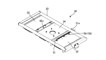
図1に示すように、座席装置10は、床面上に固定される脚台11と、脚台11に前後方向へ進退可能に支持された移動台20と、移動台20に正逆方向へ回転可能に支持された座席の台枠30と、を備えている。ここで脚台11は、「座席の固定側」に相当し、移動台20および台枠30は、「座席の可動側」に相当する。なお、座席装置10は、鉄道車両の客室内で壁(窓)際の床面上に配置され、図1中の「A」は、鉄道車両の進行方向と平行な壁の一部である。
<Overview of seat device 10>
As shown in FIG. 1, the seat device 10 has a pedestal 11 fixed on the floor surface, a moving table 20 supported by the pedestal 11 so as to be able to move forward and backward, and a moving table 20 in the forward and reverse directions. It is provided with a seat frame 30 that is rotatably supported. Here, the leg base 11 corresponds to the "fixed side of the seat", and the moving table 20 and the underframe 30 correspond to the "movable side of the seat". The seat device 10 is arranged on the floor surface near the wall (window) in the passenger compartment of the railway vehicle, and "A" in FIG. 1 is a part of the wall parallel to the traveling direction of the railway vehicle.

座席装置10では、座席は回転機構40を介して、移動台20上で回転軸周りに回転可能に支持されている。移動台20はスライド機構14を介して、脚台11上に回転機構40ごと進退可能に支持されている。また、座席装置10は、スライド機構14と回転機構40とを、それぞれ順に直接駆動する駆動機構50を備えている。なお、座席自体は図示省略したが、例えば2人掛け用の腰掛として、2つの座部と背凭れを両側方向に並設して成る。 In the seat device 10, the seat is rotatably supported around a rotation axis on the moving table 20 via a rotation mechanism 40. The moving table 20 is supported on the leg base 11 via the slide mechanism 14 so as to be able to move forward and backward together with the rotating mechanism 40. Further, the seat device 10 includes a drive mechanism 50 that directly drives the slide mechanism 14 and the rotation mechanism 40 in order. Although the seat itself is not shown, it is composed of two seats and a backrest arranged side by side in both directions, for example, as a seat for two people.

<座席の向きについて>
本実施形態に係る座席装置10は、座席の状態を、座席背面が壁Aに略平行に沿うロング状態(図1参照)と、座席背面が壁Aに略直交するクロス状態と、に変換可能である。ここでクロス状態には、座席背面が壁Aに略直交する前向きの一クロス状態(図2参照)と、一クロス状態から180度回転して後向きとなる逆クロス状態(図3参照)とがある。座席のロング状態を原位置として回転角度を0°とすると、一クロス状態の回転角度は90°であり、逆クロス状態の回転角度は270°である。以下、一クロス状態と逆クロス状態とを総称するときは、単にクロス状態と表記する。
<About the orientation of the seat>
The seat device 10 according to the present embodiment can convert the state of the seat into a long state in which the back of the seat is substantially parallel to the wall A (see FIG. 1) and a cross state in which the back of the seat is substantially orthogonal to the wall A. Is. Here, the cross state includes a forward cross state (see FIG. 2) in which the back surface of the seat is substantially orthogonal to the wall A and a reverse cross state (see FIG. 3) in which the seat is rotated 180 degrees from the one cross state and is turned backward. be. Assuming that the rotation angle is 0 ° with the seat in the long state as the original position, the rotation angle in the one-cross state is 90 ° and the rotation angle in the reverse cross state is 270 °. Hereinafter, when the one-cross state and the reverse cross state are collectively referred to, they are simply referred to as a cross state.

<脚台11>
図1,図6に示すように、脚台11は、客室内で壁Aの傍らの床面上に固定されている。脚台11は、壁Aと略直交する方向(前後方向)に長い架台状にフレーム材を組み合わせて構成されている。脚台11の上面側は略水平であり、この上面側は、長辺をなす両側端部12,12と、後側(壁A側)の短辺をなす後端部13とで囲まれているが、前側(通路側)は開放されている。脚台11は、後端部13が壁Aと略平行に近接し、両側端部12,12が壁Aと略直交して通路側に向かうように配置されている。
<Leg stand 11>
As shown in FIGS. 1 and 6, the pedestal 11 is fixed on the floor surface beside the wall A in the cabin. The pedestal 11 is configured by combining frame materials in a pedestal shape that is long in a direction (front-back direction) substantially orthogonal to the wall A. The upper surface side of the pedestal 11 is substantially horizontal, and the upper surface side is surrounded by both side end portions 12 and 12 forming a long side and a rear end portion 13 forming a short side on the rear side (wall A side). However, the front side (passage side) is open. The pedestal 11 is arranged so that the rear end portion 13 is substantially parallel to the wall A and the side end portions 12 and 12 are substantially orthogonal to the wall A and faces the passage side.

図6に示すように、両側端部12,12の上側には、座席が各位置に拘束されたとき、台枠30の下面側に係合してガタ付きを防止するための受け部材18が設けられている。また、脚台11の上面側には、次述するスライド機構14の他、後述するが台枠30の進退範囲や回転方向を規制するストッパ16,17等の関連部品が設けられている。さらに、脚台11の内部において、上面側が開放された前側(通路側)には、後述する駆動機構50の構成部品も設けられている。 As shown in FIG. 6, on the upper side of the both side end portions 12, 12, when the seat is restrained at each position, a receiving member 18 for engaging with the lower surface side of the underframe 30 to prevent rattling is provided. It is provided. Further, on the upper surface side of the pedestal 11, in addition to the slide mechanism 14 described below, related parts such as stoppers 16 and 17 that regulate the advancing / retreating range and the rotation direction of the underframe 30 are provided, which will be described later. Further, inside the pedestal 11, components of the drive mechanism 50, which will be described later, are also provided on the front side (passage side) where the upper surface side is open.

<スライド機構14>
図1,図6に示すように、脚台11の上面側には、スライド機構14を介して、移動台20が壁Aと略直交する方向(前後方向)へ進退可能に取り付けられている。スライド機構14は、脚台11の上面側に設けられた一対のガイドレール15,15を備えている。一対のガイドレール15,15は、脚台11の両側端部12,12間で互いに平行に配されている。
<Slide mechanism 14>
As shown in FIGS. 1 and 6, a moving table 20 is attached to the upper surface side of the leg base 11 via a slide mechanism 14 so as to be able to move forward and backward in a direction substantially orthogonal to the wall A (front-back direction). The slide mechanism 14 includes a pair of guide rails 15 and 15 provided on the upper surface side of the pedestal 11. The pair of guide rails 15 and 15 are arranged parallel to each other between the both side end portions 12 and 12 of the pedestal 11.

各ガイドレール15は、図示省略したが両側端部12,12より上面側の内側に向かって突設されたブラケット等に固設されている。図6に示すように、一対のガイド15,15には、次述する移動台20に連結された部品が摺動可能に嵌合している。 Although not shown, each guide rail 15 is fixed to a bracket or the like projecting toward the inside of the upper surface side from the both side end portions 12, 12. As shown in FIG. 6, the pair of guides 15 and 15 are slidably fitted with parts connected to the moving table 20 described below.

<移動台20>
図7,図8に示すように、移動台20は、脚台11の上面側で両側端部12,12の間に略水平に配置されている。移動台20は、例えば長方形の板状に金属材から構成されている。移動台20の長辺をなす両側端部21,21は、下方へフランジ状に折り曲げられている。
<Moving table 20>
As shown in FIGS. 7 and 8, the moving table 20 is arranged substantially horizontally between the end portions 12 and 12 on the upper surface side of the leg base 11. The moving table 20 is made of a metal material, for example, in the shape of a rectangular plate. Both side ends 21 and 21 forming the long side of the moving table 20 are bent downward in a flange shape.

移動台20の略中央には、座席の回転軸を中心とする円孔22が形成されており、移動台20の上面側で円孔22の周りには、座席を回転軸周りに回転させる回転機構40が設けられている。また、移動台20の前端側には、その内側へ凹むように切欠23が設けられ、この切欠23の周りに、後述する回転ロック機構60が固定されている。 A circular hole 22 centered on the rotation axis of the seat is formed in the substantially center of the moving table 20, and a rotation that rotates the seat around the rotation axis around the circular hole 22 on the upper surface side of the moving table 20. A mechanism 40 is provided. Further, a notch 23 is provided on the front end side of the moving table 20 so as to be recessed inward, and a rotation lock mechanism 60 described later is fixed around the notch 23.

移動台20の下面側には、後述する進退ロック機構70の一部を成すフレーム材24が、ブラケット25を介して長手方向に延びる状態に固設されている。フレーム材24の前後端には、後述する進退ロック機構70の係止孔72a,72bが設けられている。ここでフレーム材24がブラケット25に固定された側が前端側となり、ブラケット25より延出した側が後端側となる。また、フレーム材24の側方には、座席が通路側へ最も前進したときに、後述するストッパ19が係合するブロック状の被係合部26が設けられている。なお、脚台11の上面側には、移動台20の下面側で出っ張るフレーム材24等が進退時に干渉しない空間が設けられている。 On the lower surface side of the moving table 20, a frame material 24 forming a part of the advance / retreat lock mechanism 70, which will be described later, is fixedly fixed so as to extend in the longitudinal direction via the bracket 25. Locking holes 72a and 72b of the advancing / retreating locking mechanism 70, which will be described later, are provided at the front and rear ends of the frame material 24. Here, the side where the frame material 24 is fixed to the bracket 25 is the front end side, and the side extending from the bracket 25 is the rear end side. Further, on the side of the frame material 24, a block-shaped engaged portion 26 with which the stopper 19 described later is engaged when the seat is most advanced to the aisle side is provided. A space is provided on the upper surface side of the leg base 11 so that the frame material 24 or the like protruding on the lower surface side of the moving table 20 does not interfere with each other when advancing or retreating.

<回転機構40>
回転機構40は、移動台20上に座席の台枠30を略水平面上で正逆方向へ回転可能に支持するものである。図7に示すように、回転機構40は、内外一対のリング状の回転盤41,42が、その間にベアリング等を介在させて、互いに回転可能に組み合わされたユニットとして構成されている。
<Rotation mechanism 40>
The rotation mechanism 40 rotatably supports the underframe 30 of the seat on the moving table 20 in the forward and reverse directions on a substantially horizontal plane. As shown in FIG. 7, the rotation mechanism 40 is configured as a unit in which a pair of inner and outer ring-shaped rotary discs 41 and 42 are rotatably combined with each other with a bearing or the like interposed between them.

図7に示すように、回転機構40は、外側の回転盤41が移動台20に固定され、内側の回転盤42が台枠30の底面側に固定される。なお、座席の回転中心となる回転軸は、内外の回転盤41,42の中心線であり、本実施形態では物理的な実態を伴うものではない。 As shown in FIG. 7, in the rotation mechanism 40, the outer turntable 41 is fixed to the moving table 20, and the inner turntable 42 is fixed to the bottom surface side of the underframe 30. The rotation axis, which is the center of rotation of the seat, is the center line of the internal and external rotating discs 41 and 42, and is not accompanied by a physical condition in the present embodiment.

<台枠30>
図1に示すように、台枠30は、座席を取り付けて回転機構40に支持するものである。台枠30は、座席の座部の底面に合致する枠組状にフレーム材を組み合わせて構成されている。詳しく言えば台枠30は、図4,図9に示すように、回転機構40の上側に配される回転座板31と、該回転座板31の両側に水平面上で並ぶように連結された一対の側板32,32と、その周囲を取り囲む長方形の枠組フレーム33とから成る。また、回転座板31の上面側には、カバー板34が取り付けられている。
<Underframe 30>
As shown in FIG. 1, the underframe 30 has a seat attached and is supported by the rotation mechanism 40. The underframe 30 is configured by combining frame materials in a frame shape that matches the bottom surface of the seat portion of the seat. More specifically, as shown in FIGS. 4 and 9, the underframe 30 is connected to the rotary seat plate 31 arranged on the upper side of the rotary mechanism 40 so as to be lined up on both sides of the rotary seat plate 31 on a horizontal plane. It consists of a pair of side plates 32, 32 and a rectangular frame frame 33 surrounding the pair of side plates 32, 32. Further, a cover plate 34 is attached to the upper surface side of the rotary seat plate 31.

回転座板31の下面側は、回転機構40の内側の回転盤42に一体に固設されている。よって、台枠30上の座席は、回転機構40を介して移動台20に回転可能に支持されている。詳しく言えば回転座板31は、座席の回転軸より所定半径に広がる面積を含む略矩形状であり、その一角隅に、枠組フレーム33の一長辺より直角に外側に突出した延出部31aが形成されている。このような回転座板31には、次述する駆動機構50のうち伝達手段を成す数多の孔59,59…が穿設されている。 The lower surface side of the rotary seat plate 31 is integrally fixed to the rotary plate 42 inside the rotary mechanism 40. Therefore, the seat on the underframe 30 is rotatably supported by the moving table 20 via the rotation mechanism 40. More specifically, the rotary seat plate 31 has a substantially rectangular shape including an area extending from the rotation axis of the seat to a predetermined radius, and an extension portion 31a projecting outward at a right angle from one long side of the frame frame 33 at one corner thereof. Is formed. In such a rotary seat plate 31, a large number of holes 59, 59 ... That form a transmission means among the drive mechanisms 50 described below are bored.

<駆動機構50>
図1に示すように、駆動機構50は、スライド機構14と回転機構40(図6参照)とをそれぞれ順に直接駆動するものである。駆動機構50は、動力源であるモータ51と、該モータ51の動力により、座席の状態を変換する一過程で、先ずスライド機構14を直接駆動し次いで回転機構40を直接駆動する伝達手段と、を備えている。ここで座席の状態を変換する一過程とは、本実施形態では、ロング状態からクロス状態に変換する過程が該当する。
<Drive mechanism 50>
As shown in FIG. 1, the drive mechanism 50 directly drives the slide mechanism 14 and the rotation mechanism 40 (see FIG. 6) in order. The drive mechanism 50 includes a motor 51 as a power source, a transmission means that directly drives the slide mechanism 14 and then directly drives the rotation mechanism 40 in one process of converting the state of the seat by the power of the motor 51. It is equipped with. Here, one process of converting the state of the seat corresponds to the process of converting from the long state to the cross state in the present embodiment.

モータ51は、一般的な電動モータであり、本発明の「動力源」の一例である。詳しく言えばモータ51には、図12,図13に示すように、減速機構を内蔵したギアボックス51aが予め組み合わされており、ハウジング53に一体に固定されている。モータ51側の出力軸52には、ハウジング53内でクラッチ(図示せず)を介して駆動歯車54が固定されている。 The motor 51 is a general electric motor and is an example of the "power source" of the present invention. More specifically, as shown in FIGS. 12 and 13, the motor 51 is previously combined with a gearbox 51a having a built-in reduction mechanism, and is integrally fixed to the housing 53. A drive gear 54 is fixed to the output shaft 52 on the motor 51 side via a clutch (not shown) in the housing 53.

ハウジング53の上部には、出力軸52と離隔して平行に配された伝達軸55が軸支されており、伝達軸55には、従動歯車56が固定されている。ここで駆動歯車54と従動歯車56とは、これらの間に掛け渡されたチェーン57を介して回転力を伝達可能に連結されている。さらに、伝達軸55には、従動歯車56と同軸上に並ぶスプロケット58が固定されている。 A transmission shaft 55 arranged in parallel with the output shaft 52 is pivotally supported on the upper portion of the housing 53, and a driven gear 56 is fixed to the transmission shaft 55. Here, the drive gear 54 and the driven gear 56 are connected so as to be able to transmit a rotational force via a chain 57 spanned between them. Further, a sprocket 58 coaxially aligned with the driven gear 56 is fixed to the transmission shaft 55.

駆動機構50のうちモータ51等、座席の固定側である脚台11に配される各部品は、全てハウジング53に組み込まれてユニットとして構成されている。図6に示すように、ハウジング53は、脚台11の内部で上面側が開放された前側(通路側)に配設されている。ここでハウジング53の上部より露出するスプロケット58の上側は、脚台11の上面側の前側一端で脚台11の長手方向と平行に並び、脚台11の上面側より露出している。なお、ハウジング53の外壁には、後述するが台枠30の進退範囲を規制するストッパ19(図5参照)も設けられている。 Of the drive mechanism 50, all the parts arranged on the pedestal 11 on the fixed side of the seat, such as the motor 51, are incorporated in the housing 53 and configured as a unit. As shown in FIG. 6, the housing 53 is arranged inside the pedestal 11 on the front side (passage side) where the upper surface side is open. Here, the upper side of the sprocket 58 exposed from the upper part of the housing 53 is aligned parallel to the longitudinal direction of the pedestal 11 at one end on the front side of the upper surface side of the pedestal 11, and is exposed from the upper surface side of the pedestal 11. The outer wall of the housing 53 is also provided with a stopper 19 (see FIG. 5) that regulates the advancing / retreating range of the underframe 30, which will be described later.

<<駆動機構50の伝達手段>>
駆動機構50の伝達手段は、前記スプロケット58と、座席の可動側である台枠30に設けられ、スプロケット58が回転可能に噛み合うことで動力が伝達される数多の孔59,59…と、を備えている。詳しく言えば数多の孔59,59…は、スライド機構14を駆動するために直線状に並ぶ進退用孔群591と、該進退用孔群591の先に連続して回転機構40を駆動するために座席の回転軸と同心の円弧状に並ぶ回転用孔群592と、を含んでいる。
<< Transmission means of drive mechanism 50 >>
The transmission means of the drive mechanism 50 is provided on the sprocket 58 and the underframe 30 on the movable side of the seat, and the sprocket 58 rotatably meshes with the sprocket 58 to transmit power. It is equipped with. More specifically, the numerous holes 59, 59 ... Drive the advancing / retreating hole group 591 linearly arranged to drive the slide mechanism 14 and the rotation mechanism 40 continuously ahead of the advancing / retreating hole group 591. For this purpose, a group of rotation holes 592 concentric with the rotation axis of the seat and arranged in an arc shape are included.

図11に示すように、進退用孔群591と回転用孔群592とは、台枠30の回転座板31に設けられている。進退用孔群591は、回転座板31の一角隅の延出部31aから始まり、回転座板31の縦幅の中心付近までに亘り、枠組フレーム33の短辺と平行な直線上に沿って、各孔59が密な所定間隔おきに連設されている。この進退用孔群591は、スプロケット58との噛み合いにより、座席をロング状態から、回転しても壁Aと干渉しない位置までロング状態と平行に前進させる部分である。 As shown in FIG. 11, the advancing / retreating hole group 591 and the rotating hole group 592 are provided on the rotating seat plate 31 of the underframe 30. The advancing / retreating hole group 591 starts from the extending portion 31a at one corner of the rotating seat plate 31 and extends to the vicinity of the center of the vertical width of the rotating seat plate 31 along a straight line parallel to the short side of the framework frame 33. , Each hole 59 is connected at close predetermined intervals. The advancing / retreating hole group 591 is a portion that advances the seat from the long state to a position where it does not interfere with the wall A even if it is rotated, in parallel with the long state by engaging with the sprocket 58.

一方、回転用孔群592は、進退用孔群591の終端の先にそのまま続いて、座席の回転軸と同心の円弧上に沿って、各孔59が密な所定間隔おきに連設されている。ここで回転用孔群592の曲率は、スプロケット58が回転可能に噛み合う範囲内に設定されている。詳しく言えば回転用孔群592は、座席が270°まで回転する回転角度に亘って延びており、進退用孔群591の終端に続く始端の0°から90°までの範囲の回転用孔群592aが、一クロス状態まで回転させる部分であり、90°から270°までの範囲の回転用孔群592bが、クロス状態から逆クロスまで回転させる部分である。 On the other hand, in the rotation hole group 592, following the end of the advance / retreat hole group 591 as it is, each hole 59 is continuously provided at close predetermined intervals along an arc concentric with the rotation axis of the seat. There is. Here, the curvature of the rotation hole group 592 is set within a range in which the sprocket 58 rotatably meshes. More specifically, the rotation hole group 592 extends over a rotation angle at which the seat rotates up to 270 °, and the rotation hole group in the range of 0 ° to 90 ° at the start end following the end of the advance / retreat hole group 591. 592a is a portion to be rotated to one cross state, and the rotation hole group 592b in the range of 90 ° to 270 ° is a portion to be rotated from the cross state to the reverse cross.

座席がロング状態にあるとき、モータ51によりスプロケット58が回転すると、数多の孔59,59…は順次移動する。そのため、モータ51の動力によって、先ずはスライド機構14が直接駆動され、次いで回転機構40が直接駆動される。すなわち、座席のロング状態から一クロス状態への変換と、一クロス状態から逆クロス状態への変換は、モータ51の正回転により行われる。一方、座席の逆クロス状態から一クロス状態への変換と、一クロス状態からロング状態への変換は、モータ51の逆回転により行われるように設定されている。なお、回転機構40は、手動でも座席を回転可能となっている。 When the sprocket 58 is rotated by the motor 51 when the seat is in the long state, the numerous holes 59, 59 ... Are sequentially moved. Therefore, the slide mechanism 14 is first directly driven by the power of the motor 51, and then the rotation mechanism 40 is directly driven. That is, the conversion from the long state of the seat to the one-cross state and the conversion from the one-cross state to the reverse cross state are performed by the forward rotation of the motor 51. On the other hand, the conversion from the reverse cross state of the seat to the one-cross state and the conversion from the one-cross state to the long state are set to be performed by the reverse rotation of the motor 51. The rotation mechanism 40 can rotate the seat manually.

ただし、鉄道車両の客室内において、座席装置10は、進行方向の両側の壁Aに沿って、それぞれ一列ずつ前後に並ぶように配置され、両列の間が通路となる。よって、両列の座席装置10において、回転座板31における進退用孔群591と回転用孔群592の形状は、互いに左右対称となるように設けることになる。この場合、一方の壁A側の座席装置10における座席の正回転は、他方の壁A側の座席装置10における座席の逆回転となる。 However, in the passenger compartment of a railroad vehicle, the seating devices 10 are arranged so as to be lined up in a row in front and behind along the walls A on both sides in the traveling direction, and a passage is provided between the two rows. Therefore, in the seating devices 10 in both rows, the shapes of the advancing / retreating hole group 591 and the rotating hole group 592 in the rotating seat plate 31 are provided so as to be symmetrical with each other. In this case, the forward rotation of the seat in the seat device 10 on the one wall A side is the reverse rotation of the seat in the seat device 10 on the other wall A side.

<回転ロック機構60>
座席装置10は、台枠30(座席)をロング状態、一クロス状態、逆クロス状態のそれぞれの回転位置で回転不能に拘束する回転ロック機構60を備えている。回転ロック機構60は、台枠30を移動台20に対して回転不能に拘束するものであり、これとは別に、移動台20を座席の固定側である脚台11に対して進退不能に拘束するために後述の進退ロック機構70も備えている。
<Rotation lock mechanism 60>
The seat device 10 is provided with a rotation lock mechanism 60 that restrains the underframe 30 (seat) so as not to rotate at each of the rotation positions of the long state, the one-cross state, and the reverse cross state. The rotation lock mechanism 60 restrains the underframe 30 so as not to rotate with respect to the moving table 20, and separately, restrains the moving table 20 so as not to advance or retreat with respect to the leg base 11 which is the fixed side of the seat. The advance / retreat lock mechanism 70, which will be described later, is also provided for this purpose.

図6,図1~図3に示すように、回転ロック機構60は、移動台20側から台枠30(図1参照)に亘り上下に出没可能なロックピン61と、台枠30に設けられ前記ロックピン61が係脱する係止孔62a,62b,62cとを備えている。図9,図11に示すように、各係止孔62a,62b,62cは、台枠30の回転座板31のうち、延出部31aが直角に出た前端縁の略中央と、両側端縁の略中央に、それぞれ合計3つ設けられている。 As shown in FIGS. 6, 1 to 3, the rotation lock mechanism 60 is provided on the underframe 30 and a lock pin 61 that can move up and down from the moving table 20 side to the underframe 30 (see FIG. 1). It is provided with locking holes 62a, 62b, 62c to which the lock pin 61 engages and disengages. As shown in FIGS. 9 and 11, each of the locking holes 62a, 62b, 62c is formed at substantially the center of the front edge of the rotating seat plate 31 of the underframe 30 where the extending portion 31a protrudes at a right angle, and both side ends. A total of three are provided in the center of the edge.

図14,図15に示すように、ロックピン61は、ユニット60aに組み込まれている。図6に示すように、ユニット60aは、移動台20の前端側(図7中の切欠23の周り)に固定されている。ロックピン61は、上方へ突出して係止孔62a,62b,62cに嵌入するロック位置と、下方へ没入して係止孔62a,62b,62cから外れるロック解除位置と、に動作する。 As shown in FIGS. 14 and 15, the lock pin 61 is incorporated in the unit 60a. As shown in FIG. 6, the unit 60a is fixed to the front end side of the moving table 20 (around the notch 23 in FIG. 7). The lock pin 61 operates at a lock position that protrudes upward and fits into the locking holes 62a, 62b, 62c, and an unlocking position that immerses downward and disengages from the locking holes 62a, 62b, 62c.

ロックピン61は、座席がロング状態、一クロス状態、逆クロス状態に変換されたとき、それぞれの位置で上下に合致する台枠30側の係止孔62a,62b,62cに嵌入して拘束する。すなわち、図1に示すロング状態のとき、ロックピン61は、回転座板31の前端縁にある係止孔62aに嵌入する。また、図2に示す一クロス状態のとき、ロックピン61は、回転座板31の一側端縁にある係止孔62bに嵌入する。さらに、図3に示す逆クロス状態のとき、ロックピン61は、回転座板31の他側端縁にある係止孔62cに嵌入する。 When the seat is converted into the long state, the one-cross state, and the reverse-cross state, the lock pin 61 is fitted into and restrained by the locking holes 62a, 62b, 62c on the underframe 30 side that match the upper and lower positions at the respective positions. .. That is, in the long state shown in FIG. 1, the lock pin 61 is fitted into the locking hole 62a at the front end edge of the rotary seat plate 31. Further, in the one-cross state shown in FIG. 2, the lock pin 61 is fitted into the locking hole 62b on one side edge of the rotary seat plate 31. Further, in the reverse cross state shown in FIG. 3, the lock pin 61 is fitted into the locking hole 62c at the other end edge of the rotary seat plate 31.

ロックピン61が組み込まれたユニット60aには、ロックピン61を上方へ突出させるロック位置に常時付勢するバネ部材(図示せず)と、ロックピン61をバネ部材の付勢力に抗して下方のロック解除位置に没入させるリンク60bとが、それぞれ設けられている。ここでリンク60bには、図示省略したが電動操作用と手動操作用の各ケーブルが連結されている。 In the unit 60a in which the lock pin 61 is incorporated, a spring member (not shown) that constantly urges the lock position to project the lock pin 61 upward, and a lock pin 61 downward against the urging force of the spring member. A link 60b is provided so as to be immersed in the unlocked position of the above. Here, although not shown, cables for electric operation and cables for manual operation are connected to the link 60b.

ロックピン61は、バネ部材の付勢力によって通常はロック位置に維持されるが、リンク60bが各ケーブルによって引かれると、バネ部材の付勢力に抗してロック解除位置に没入するように構成されている。ここで手動操作用のケーブルの他端は、例えば脚台11側に設けられた足踏ペダル(図示せず)に連結されており、足踏ペダルを踏み込む操作によってケーブルが引っ張られ、回転ロック機構60の拘束を解除することができる。 The lock pin 61 is normally maintained in the locked position by the urging force of the spring member, but when the link 60b is pulled by each cable, it is configured to immerse in the unlocked position against the urging force of the spring member. ing. Here, the other end of the cable for manual operation is connected to, for example, a foot pedal (not shown) provided on the footrest 11 side, and the cable is pulled by the operation of stepping on the foot pedal, and the rotation lock mechanism. The restraint of 60 can be released.

一方、電動操作用のケーブルを引っ張る動力源は、例えば駆動機構50のモータ51が兼用されている。前述したモータ51の出力軸52はクラッチを備えており、クラッチの切り替えによって、スライド機構14および回転機構40を直接駆動する動力系と、ロックピン61を没入させて拘束を解除する動作と、に切り替え可能に構成されている。すなわち、1つのモータ51によって、座席の状態の変換とロック解除の2つの動作を行うことができる。なお、モータ51のクラッチに関する構成は、一般的であるので詳細な説明は省略する。 On the other hand, as the power source for pulling the cable for electric operation, for example, the motor 51 of the drive mechanism 50 is also used. The output shaft 52 of the motor 51 described above is provided with a clutch, and the power system that directly drives the slide mechanism 14 and the rotation mechanism 40 by switching the clutch, and the operation of immersing the lock pin 61 to release the restraint. It is configured to be switchable. That is, one motor 51 can perform two operations of changing the state of the seat and unlocking the seat. Since the configuration of the clutch of the motor 51 is general, detailed description thereof will be omitted.

本実施形態に係る回転ロック機構60では、座席がロング状態にあるときは、回転ロック機構60の拘束を、手動操作、すなわち足踏ペダルを踏み込む操作では解除できず、モータ51による電動操作用のケーブルを介しての電動操作のみで解除することができるように構成されている。ここで電動操作は、車両の乗務員や駅員によって行われるものであり、手動操作は主に乗客によって行われる。 In the rotation lock mechanism 60 according to the present embodiment, when the seat is in a long state, the restraint of the rotation lock mechanism 60 cannot be released by a manual operation, that is, an operation of depressing the foot pedal, and the motor 51 is used for electric operation. It is configured so that it can be released only by electric operation via a cable. Here, the electric operation is performed by the crew of the vehicle or the station staff, and the manual operation is mainly performed by the passengers.

また、座席がロング状態にあるときに、回転ロック機構60のロック解除操作をできなくするための構成としては、具体的には例えば、ロックピン61がロック位置から解除位置に至るストロークに電動操作と手動操作とで差を設けたり、座席がロング状態にあるときは、足踏ペダルを操作不能な状態に収納すること等が考えられる。 Further, as a configuration for disabling the unlocking operation of the rotation lock mechanism 60 when the seat is in the long state, specifically, for example, the lock pin 61 is electrically operated in the stroke from the lock position to the release position. It is conceivable to make a difference between the operation and manual operation, or to store the foot pedal in an inoperable state when the seat is in a long state.

<進退ロック機構70>
座席装置10は、座席がロング状態のとき、移動台20を壁A側へ最も後退(接近)した後退位置と、座席がクロス状態のとき、移動台20を通路側へ最も前進した前進位置と、に進退不能に拘束する進退ロック機構70を備えている。進退ロック機構70は、前記回転ロック機構60とは別に、移動台20を脚台11に対して進退不能に拘束するものである。進退ロック機構70によれば、回転ロック機構60の拘束を解除した状態でも、座席の進退のみ不能に拘束することが可能となる。
<Advance / retreat lock mechanism 70>
The seat device 10 has a retracted position in which the moving table 20 is most retracted (approached) to the wall A side when the seat is in the long state, and a forward position in which the moving table 20 is most advanced toward the aisle side when the seat is in the cross state. It is equipped with an advance / retreat lock mechanism 70 that restrains the person from advancing / retreating. The advance / retreat lock mechanism 70, apart from the rotation lock mechanism 60, restrains the moving table 20 with respect to the leg base 11 so as not to advance / retreat. According to the advance / retreat lock mechanism 70, even in a state where the restraint of the rotation lock mechanism 60 is released, it is possible to restrain only the advance / retreat of the seat.

図1,図16,図8に示すように、進退ロック機構70は、脚台11側から移動台20に亘り上下に出没可能なロックピン71と、移動台20に設けられて前記ロックピン71が係脱する係止孔72a,72bとを備えている。図8に示すように、各係止孔72a,72bは、移動台20の後方下側で前後方向に延びるフレーム材24の前後端に、それぞれ合計2つ設けられている。 As shown in FIGS. 1, 16 and 8, the advance / retreat lock mechanism 70 includes a lock pin 71 that can move up and down from the leg stand 11 side to the moving table 20 and the lock pin 71 provided on the moving table 20. It is provided with locking holes 72a and 72b for engaging and disengaging. As shown in FIG. 8, a total of two locking holes 72a and 72b are provided at the front and rear ends of the frame member 24 extending in the front-rear direction on the rear lower side of the moving table 20.

図16,図17に示すように、ロックピン71は、ユニット70aに組み込まれている。図1,図5に示すように、ユニット70aは、移動台20の下側に位置する脚台11の内側に固定されている。ロックピン71は、上方へ突出して係止孔72a,72bに嵌入するロック位置と、下方へ没入して係止孔72a,72bから外れるロック解除位置と、に動作する。 As shown in FIGS. 16 and 17, the lock pin 71 is incorporated in the unit 70a. As shown in FIGS. 1 and 5, the unit 70a is fixed to the inside of the pedestal 11 located below the moving table 20. The lock pin 71 operates at a lock position that protrudes upward and fits into the locking holes 72a and 72b, and an unlocking position that immerses downward and disengages from the locking holes 72a and 72b.

ロックピン71は、座席がロング状態ないしクロス状態に変換されたとき、それぞれの位置で上下に合致する移動台20側の各係止孔72a,72bに嵌入して拘束する。すなわち、図1に示すロング状態のとき、ロックピン71は、フレーム材24の前端側にある係止孔72aに嵌入する。また、図2に示す一クロス状態のとき、ロックピン71は、フレーム材24の後端側にある係止孔72bに嵌入する。同様に、図3に示す逆クロス状態のときも、ロックピン71は係止孔72bに嵌入する。 When the seat is converted into a long state or a cross state, the lock pin 71 is fitted into and restrained into the locking holes 72a and 72b on the moving table 20 side that match the upper and lower positions at the respective positions. That is, in the long state shown in FIG. 1, the lock pin 71 is fitted into the locking hole 72a on the front end side of the frame material 24. Further, in the one-cross state shown in FIG. 2, the lock pin 71 is fitted into the locking hole 72b on the rear end side of the frame material 24. Similarly, even in the reverse cross state shown in FIG. 3, the lock pin 71 is fitted into the locking hole 72b.

図16,図17に示すように、ユニット70aにおいて、ロックピン71は、バネ部材73によって上方へ突出するロック位置に常時付勢されている。ロックピン71には、バネ部材73の付勢力に抗して、下方の解除位置に変位させるリンク74が連結されている。ここでリンク74は、回動中心である枢軸75より側方へ延びる一端64aがロックピン71の下端側に押し引き可能に連結され、枢軸65より下方へ延びる他端74aは、図示省略した例えばソレノイド等の動力源により押し引き可能に構成されている。 As shown in FIGS. 16 and 17, in the unit 70a, the lock pin 71 is constantly urged to a lock position protruding upward by the spring member 73. A link 74 that is displaced to a lower release position against the urging force of the spring member 73 is connected to the lock pin 71. Here, in the link 74, one end 64a extending laterally from the pivot 75, which is the center of rotation, is connected to the lower end side of the lock pin 71 so as to be pushable and pullable, and the other end 74a extending downward from the pivot 65 is not shown, for example. It is configured to be pushable and pullable by a power source such as a solenoid.

すなわち、ロックピン71は、バネ部材73の付勢力によって通常はロック位置に維持されるが、リンク74の他端74aが駆動手段によって引かれると、バネ部材73の付勢力に抗してロック解除位置に変位する。よって、ロックピン71は、前記回転ロック機構60のロックピン61の場合と異なり、電動操作でのみ動作し、手動操作では拘束を解除することができない。なお、回転ロック機構60、進退ロック機構70には、停電等の非常時に座席の状態に関わらず拘束を解除できるように、それぞれ非常用の手動操作部を別途設けると良い。 That is, the lock pin 71 is normally maintained in the locked position by the urging force of the spring member 73, but when the other end 74a of the link 74 is pulled by the driving means, the lock pin 71 is unlocked against the urging force of the spring member 73. Displace to position. Therefore, unlike the case of the lock pin 61 of the rotation lock mechanism 60, the lock pin 71 operates only by electric operation, and the restraint cannot be released by manual operation. The rotation lock mechanism 60 and the advance / retreat lock mechanism 70 may be provided with separate emergency manual operation units so that the restraint can be released regardless of the seat condition in an emergency such as a power failure.

<各種ストッパ>
図6に示すように、脚台11の上面側における後端側の一角隅には、座席がロング状態にあるときに、座席の後退を阻止するストッパ16が設けられている。ストッパ16は、バネ状に構成されており、座席がロング状態にあるとき、台枠30の下面側に設けられたピン状の被係合部35(図9参照)が係合することで、台枠30が壁A側へこれ以上後退しないように規制するものである。
<Various stoppers>
As shown in FIG. 6, a stopper 16 for preventing the seat from retreating when the seat is in the long state is provided at one corner on the rear end side of the upper surface side of the pedestal 11. The stopper 16 is configured in a spring shape, and when the seat is in a long state, the pin-shaped engaged portion 35 (see FIG. 9) provided on the lower surface side of the underframe 30 engages with the stopper 16. The underframe 30 is regulated so as not to recede further toward the wall A side.

一方、図5に示すように、脚台11の内部におけるハウジング53の外壁には、座席がクロス状態にあるときに、座席の前進を阻止するストッパ19が設けられている。ストッパ19は、バネ状に構成されており、座席がクロス状態にあるとき、移動台20側のフレーム材24に設けられたブロック状の被係合部26が係合することで、台枠30が通路側へこれ以上前進しないように規制するものである。 On the other hand, as shown in FIG. 5, the outer wall of the housing 53 inside the pedestal 11 is provided with a stopper 19 that prevents the seat from advancing when the seat is in the crossed state. The stopper 19 is configured in a spring shape, and when the seat is in a crossed state, the block-shaped engaged portion 26 provided on the frame material 24 on the moving table 20 side engages with the underframe 30. Is to prevent the vehicle from moving further toward the aisle.

また、図6に示すように、脚台11の上面側における後端寄りの一側端には、座席が逆クロス状態にあるときに、座席の回転を阻止するストッパ17も設けられている。ストッパ17は、ダンパー状に構成されており、座席が逆クロス状態にあるとき、台枠30の下面側に設けられたピン状の被係合部36(図9参照)が係合することで、台枠30が270°以上回転しないように規制するものである。 Further, as shown in FIG. 6, a stopper 17 for preventing the rotation of the seat when the seat is in the reverse cross state is also provided at one end near the rear end on the upper surface side of the pedestal 11. The stopper 17 is configured in a damper shape, and when the seat is in the reverse cross state, the pin-shaped engaged portion 36 (see FIG. 9) provided on the lower surface side of the underframe 30 engages with the stopper 17. , The underframe 30 is regulated so as not to rotate more than 270 °.

<座席装置10の動作>
次に、図18~図21に基づいて、座席の状態を変換する動作について説明する。図18(a)に示すように、座席がロング状態にあるとき、台枠30は、壁A側へ最も後退(接近)した後退位置(スライド初期)にある。また、台枠30の長辺(座席背面)は、壁Aに略平行に沿って回転角度は0°となっている。このとき、駆動機構50では、スプロケット58の歯が、図11に示す台枠30の回転座板31の延出部31aから始まる進退用孔群591の始端側に噛み合っている。
<Operation of seat device 10>
Next, the operation of converting the state of the seat will be described with reference to FIGS. 18 to 21. As shown in FIG. 18A, when the seat is in the long state, the underframe 30 is in the retracted position (initial stage of slide) most retracted (approached) to the wall A side. Further, the long side (back surface of the seat) of the underframe 30 has a rotation angle of 0 ° along substantially parallel to the wall A. At this time, in the drive mechanism 50, the teeth of the sprocket 58 mesh with the start end side of the advancing / retreating hole group 591 starting from the extending portion 31a of the rotating seat plate 31 of the underframe 30 shown in FIG.

また、座席がロング状態にあるときは、進退ロック機構70により、座席の台枠30は、移動台20と共に脚台11に対して進退不能に拘束されている。すなわち、図16に示す進退ロック機構70のロックピン71が、移動台20側のフレーム材24の前端側にある係止孔72a(図8参照)に嵌入している。また、脚台11の上面側にあるバネ状のストッパ16(図6参照)に対して、台枠30の下面側にあるピン状の被係合部35(図9参照)が係合している。 Further, when the seat is in the long state, the seat frame 30 is restrained from advancing and retreating with respect to the leg base 11 together with the moving table 20 by the advancing / retreating lock mechanism 70. That is, the lock pin 71 of the advance / retreat lock mechanism 70 shown in FIG. 16 is fitted into the locking hole 72a (see FIG. 8) on the front end side of the frame material 24 on the moving table 20 side. Further, the pin-shaped engaged portion 35 (see FIG. 9) on the lower surface side of the underframe 30 is engaged with the spring-shaped stopper 16 (see FIG. 6) on the upper surface side of the pedestal 11. There is.

さらに、回転ロック機構60により、座席の台枠30は、移動台20に対して回転不能に拘束されている。すなわち、図14に示す回転ロック機構60のロックピン61が、台枠30の回転座板31の前端縁にある係止孔62a(図9参照)に嵌入している。以上により、座席を、図1に示すロング状態に確実に保持することができる。 Further, the rotation lock mechanism 60 restrains the underframe 30 of the seat from rotating with respect to the moving table 20. That is, the lock pin 61 of the rotary lock mechanism 60 shown in FIG. 14 is fitted into the locking hole 62a (see FIG. 9) at the front end edge of the rotary seat plate 31 of the underframe 30. As a result, the seat can be reliably held in the long state shown in FIG.

<<ロング状態から一クロス状態>>
座席を、ロング状態(回転角度0°)から一クロス状態(回転角度90°)に変換するには、図18(a)に示すロング状態(回転角度0°)において、先ず進退ロック機構70の拘束を解除する。すると、台枠30は、脚台11の上面側にあるバネ状のストッパ16の付勢力によって、少しだけ通路側(図18(a)中で上方)へ移動台20ごと前進して位置ズレする。これにより、初期動作が補助されるだけでなく、一時的にロック解除されたロックピン71が、再び係止孔72aに嵌入することを防ぐことができる。なお、進退ロック機構70のロック解除は、電動操作のみで可能である。
<< From long state to one cross state >>
In order to convert the seat from the long state (rotation angle 0 °) to the one-cross state (rotation angle 90 °), first, in the long state (rotation angle 0 °) shown in FIG. 18A, the advance / retreat lock mechanism 70 is used. Release the restraint. Then, the underframe 30 is slightly moved forward together with the moving table 20 to the aisle side (upward in FIG. 18A) due to the urging force of the spring-shaped stopper 16 on the upper surface side of the leg base 11, and the position is displaced. .. This not only assists the initial operation, but also prevents the temporarily unlocked lock pin 71 from refitting into the locking hole 72a. The advance / retreat lock mechanism 70 can be unlocked only by electric operation.

そして、駆動機構50のモータ51を駆動して正回転させると、先ずは伝達手段によってスライド機構14が直接駆動され、台枠30は移動台20ごと通路側へ前進する。すなわち、モータ51の回転により伝達手段のスプロケット58が回転駆動し、スプロケット58の歯が噛み合っている台枠30側の進退用孔群591が、通路側へ壁Aと直交する直線方向に移動する。図18(b)は、台枠30が前述した後退位置(スライド初期)から通路側へ中間まで前進した中間位置(スライド中間)を示している。このとき、スプロケット58の歯は、図11に示す進退用孔群591の略中間に噛み合っている。 Then, when the motor 51 of the drive mechanism 50 is driven to rotate in the forward direction, the slide mechanism 14 is first directly driven by the transmission means, and the underframe 30 moves forward together with the moving table 20 toward the aisle side. That is, the rotation of the motor 51 drives the sprocket 58 of the transmission means to rotate, and the advancing / retreating hole group 591 on the underframe 30 side in which the teeth of the sprocket 58 are engaged moves in a linear direction orthogonal to the wall A toward the passage side. .. FIG. 18B shows an intermediate position (intermediate slide) in which the underframe 30 advances from the retracted position (initial stage of slide) described above to the middle toward the aisle side. At this time, the teeth of the sprocket 58 mesh with each other substantially in the middle of the advancing / retreating hole group 591 shown in FIG.

続いて、スプロケット58の回転駆動により、進退用孔群591がさらに通路側へ直線方向に移動すると、図18(c)に示すように、台枠30は通路側へ最も前進した前進位置(スライド最大)に到達する。すると、移動台20側にある被係合部26が、脚台11の内部にあるバネ状のストッパ19に係合するため、台枠30は通路側へこれ以上前進しないように規制される。このとき、スプロケット58の歯は、図11に示す進退用孔群591の終端側、すなわち回転用孔群592との境界付近に噛み合っている。 Subsequently, when the advancing / retreating hole group 591 further moves in a linear direction toward the passage side due to the rotational drive of the sprocket 58, the underframe 30 moves forward most toward the passage side (slide) as shown in FIG. 18 (c). Maximum) is reached. Then, since the engaged portion 26 on the moving table 20 side engages with the spring-shaped stopper 19 inside the leg base 11, the underframe 30 is restricted so as not to advance further to the aisle side. At this time, the teeth of the sprocket 58 mesh with the terminal side of the advancing / retreating hole group 591 shown in FIG. 11, that is, near the boundary with the rotating hole group 592.

また、台枠30が前進位置(スライド最大)に到達すると、進退ロック機構70により、座席の台枠30は、移動台20と共に脚台11に対して進退不能に拘束される。すなわち、図16に示す進退ロック機構70のロックピン71が、移動台20側のフレーム材24の後端側にある係止孔72b(図8参照)に嵌入する。 Further, when the underframe 30 reaches the forward position (maximum slide), the underframe 30 of the seat is restrained by the advance / retreat lock mechanism 70 with respect to the leg base 11 together with the moving table 20. That is, the lock pin 71 of the advance / retreat lock mechanism 70 shown in FIG. 16 is fitted into the locking hole 72b (see FIG. 8) on the rear end side of the frame material 24 on the moving table 20 side.

次いで、駆動機構50のモータ51を駆動して正回転させると、今度は伝達手段によって回転機構40が直接駆動され、図18(c)において、台枠30は脚台11(移動台20)に対して回転軸周りに、図中で反時計回りに回転を開始する。すなわち、モータ51の回転により伝達手段のスプロケット58が回転駆動し、スプロケット58の歯が噛み合っている台枠30側の回転用孔群592が、その始端の0°から90°までの範囲に亘る回転用孔群592aの分だけ回転軸を中心とする円周方向に移動する。 Next, when the motor 51 of the drive mechanism 50 is driven to rotate in the forward direction, the rotation mechanism 40 is directly driven by the transmission means, and in FIG. 18C, the underframe 30 is attached to the pedestal 11 (moving table 20). On the other hand, it starts rotating counterclockwise in the figure around the axis of rotation. That is, the rotation of the motor 51 drives the sprocket 58 of the transmission means to rotate, and the rotation hole group 592 on the underframe 30 side in which the teeth of the sprocket 58 are engaged extends from 0 ° to 90 ° at the starting end thereof. It moves in the circumferential direction about the rotation axis by the amount of the rotation hole group 592a.

図18(c)に続く図19(d)は、台枠30の回転角度が30°の状態を示し、図19(e)は、台枠30の回転角度が60°の状態を示し、図19(f)は、台枠30の回転角度が90°の一クロス状態に到達した状態を示している。ここで台枠30が一クロス状態のとき、スプロケット58の歯は、回転用孔群592のうち回転用孔群592aの終端側に噛み合っている。 FIG. 19D following FIG. 18C shows a state in which the rotation angle of the underframe 30 is 30 °, and FIG. 19E shows a state in which the rotation angle of the underframe 30 is 60 °. 19 (f) shows a state in which the rotation angle of the underframe 30 reaches a cross state of 90 °. Here, when the underframe 30 is in the one-cross state, the teeth of the sprocket 58 mesh with the terminal side of the rotation hole group 592a of the rotation hole group 592.

このように、台枠30が図18(c)に示す前進位置から90°回転するときには、回転ロック機構60による台枠30の拘束は解除されている必要がある。回転ロック機構60の拘束を解除するタイミングは、例えば図18(c)に示す前進位置に到達した時点でも良く、あるいは図18(a)に示すロング状態から台枠30の前進開始前に予め回転ロック機構60の拘束を解除するようにしても良い。 As described above, when the underframe 30 rotates 90 ° from the forward position shown in FIG. 18C, the restraint of the underframe 30 by the rotation lock mechanism 60 needs to be released. The timing for releasing the restraint of the rotation lock mechanism 60 may be, for example, when it reaches the forward position shown in FIG. 18 (c), or it rotates in advance from the long state shown in FIG. 18 (a) before the start of forward movement of the underframe 30. The restraint of the lock mechanism 60 may be released.

そして、台枠30がクロス状態になると、再び回転ロック機構60により、台枠30は、移動台20に対して回転不能に拘束される。すなわち、図14に示す回転ロック機構60のロックピン61が、台枠30の回転座板31の一側端にある係止孔62b(図9参照)に嵌入する。以上により、座席を、図2に示す一クロス状態に確実に保持することができる。 Then, when the underframe 30 is in the cross state, the underframe 30 is restrained to be non-rotatable with respect to the moving table 20 by the rotation lock mechanism 60 again. That is, the lock pin 61 of the rotary lock mechanism 60 shown in FIG. 14 is fitted into the locking hole 62b (see FIG. 9) at one side end of the rotary seat plate 31 of the underframe 30. As a result, the seat can be reliably held in the one-cross state shown in FIG.

<<一クロス状態から逆クロス状態>>
座席を、一クロス状態から逆クロス状態に変換するには、図19(f)に示す一クロス状態において、先ず回転ロック機構60の拘束を解除する。ここでの拘束を解除する操作は、着座者による手動操作か、あるいはモータ51による電動操作のどちらでも可能である。
<< From one cross state to reverse cross state >>
In order to convert the seat from the one-cross state to the reverse-cross state, the restraint of the rotation lock mechanism 60 is first released in the one-cross state shown in FIG. 19 (f). The operation for releasing the restraint here can be either a manual operation by the seated person or an electric operation by the motor 51.

そして、駆動機構50のモータ51を駆動して正回転させると、伝達手段によって回転機構40が直接駆動され、図19(f)において、台枠30は脚台11(移動台20)に対して回転軸周りに、図中で反時計回りに回転を開始する。すなわち、モータ51の回転により伝達手段のスプロケット58が回転駆動し、スプロケット58の歯が噛み合っている台枠30側の回転用孔群592(図11参照)が、その途中の90°から270°までの範囲に亘る回転用孔群592bの分だけ回転軸を中心とする円周方向に移動する。 Then, when the motor 51 of the drive mechanism 50 is driven to rotate in the forward direction, the rotation mechanism 40 is directly driven by the transmission means, and in FIG. 19 (f), the underframe 30 is relative to the pedestal 11 (moving table 20). Rotation starts counterclockwise in the figure around the axis of rotation. That is, the rotation of the motor 51 drives the sprocket 58 of the transmission means to rotate, and the rotation hole group 592 (see FIG. 11) on the underframe 30 side in which the teeth of the sprocket 58 are engaged is 90 ° to 270 ° in the middle. It moves in the circumferential direction about the rotation axis by the amount of the rotation hole group 592b over the range up to.

図19(f)に続く図20(g)は、台枠30の回転角度が120°の状態を示し、図20(h)は、台枠30の回転角度が150°の状態を示し、図20(i)は、台枠30の回転角度が180°の状態を示している。ここで台枠30の回転角度が180°に到達したとき、スプロケット58の歯は、図11に示す回転用孔群592bの略中間に噛み合っている。 FIG. 20 (g) following FIG. 19 (f) shows a state in which the rotation angle of the underframe 30 is 120 °, and FIG. 20 (h) shows a state in which the rotation angle of the underframe 30 is 150 °. 20 (i) shows a state in which the rotation angle of the underframe 30 is 180 °. Here, when the rotation angle of the underframe 30 reaches 180 °, the teeth of the sprocket 58 mesh with each other substantially in the middle of the rotation hole group 592b shown in FIG.

引き続き、スプロケット58の回転駆動により、台枠30はそのままさらに回転し、図21(j)は、台枠30の回転角度が210°の状態を示し、図21(k)は、台枠30の回転角度が240°の状態を示し、図21(l)は、台枠30の回転角度が270°の逆クロス状態に到達した状態を示している。ここで台枠30が逆クロス状態のとき、スプロケット58の歯は、図11に示す回転用孔群592bの終端側に噛み合っている。 Subsequently, the underframe 30 is further rotated by the rotational drive of the sprocket 58, FIG. 21 (j) shows a state where the rotation angle of the underframe 30 is 210 °, and FIG. 21 (k) shows the underframe 30. A state in which the rotation angle is 240 ° is shown, and FIG. 21 (l) shows a state in which the rotation angle of the underframe 30 reaches a reverse cross state of 270 °. Here, when the underframe 30 is in the reverse cross state, the teeth of the sprocket 58 mesh with the terminal side of the rotation hole group 592b shown in FIG.

そして、台枠30が逆クロス状態になると、再び回転ロック機構60により、台枠30は、移動台20に対して回転不能に拘束される。すなわち、図14に示す回転ロック機構60のロックピン61が、台枠30の回転座板31の他側端にある係止孔62c(図9参照)に嵌入する。以上により、座席を、図3に示す逆クロス状態に確実に保持することができる。 Then, when the underframe 30 is in the reverse cross state, the underframe 30 is restrained by the rotation lock mechanism 60 so as not to rotate with respect to the moving table 20. That is, the lock pin 61 of the rotary lock mechanism 60 shown in FIG. 14 is fitted into the locking hole 62c (see FIG. 9) at the other end of the rotary seat plate 31 of the underframe 30. As a result, the seat can be reliably held in the reverse cross state shown in FIG.

<<逆クロス状態から一クロス状態>>
また、座席を逆クロス状態から一クロス状態に戻す場合は、同様な説明は省略するが、回転ロック機構60による拘束を解除してから、今度はモータ51を逆回転させることにより、前述した動作とは逆の動作が行われる。かかる動作は、モータ51の駆動による電動操作に限らず、手動操作によっても行うことができる。
<< From reverse cross state to one cross state >>
Further, when returning the seat from the reverse cross state to the one cross state, the same description is omitted, but the above-mentioned operation is performed by releasing the restraint by the rotation lock mechanism 60 and then rotating the motor 51 in the reverse direction. The opposite operation is performed. Such an operation can be performed not only by an electric operation driven by the motor 51 but also by a manual operation.

<<一クロス状態からロング状態>>
さらに、座席を一クロス状態から元のロング状態に戻すに場合も、同様な説明は省略するが、回転ロック機構60による拘束を解除すると共に、進退ロック機構70による拘束も解除してから、モータ51を逆回転させることにより、前述した動作とは逆の動作が行われる。かかる動作は、モータ51の駆動による電動操作によってのみ行うことができる。
<< From one cross state to long state >>
Further, when returning the seat from the one-cross state to the original long state, the same explanation is omitted, but the restraint by the rotation lock mechanism 60 is released, and the restraint by the advance / retreat lock mechanism 70 is also released, and then the motor. By rotating the 51 in the reverse direction, an operation opposite to the above-mentioned operation is performed. Such an operation can be performed only by an electric operation driven by the motor 51.

<本発明の構成と作用効果>
以上、本発明の実施形態について説明したが、本発明は前述した実施形態に限定されるものではない。前述した実施形態から導かれる本発明について、以下に説明する。
<Structure and action of the present invention>
Although the embodiments of the present invention have been described above, the present invention is not limited to the above-described embodiments. The present invention derived from the above-described embodiment will be described below.

先ず、本発明は、
座席の状態を変換可能な座席装置10において、
座席を回転軸周りに回転させる回転機構40と、
座席を固定側より前記回転機構40ごと進退させるスライド機構14と、
前記スライド機構14と前記回転機構40とをそれぞれ順に直接駆動する駆動機構50と、を備え、
前記駆動機構50は、座席の固定側に設けられた動力源51と、該動力源51の動力により座席の状態を変換する一過程で、先ず前記スライド機構14を直接駆動した後、次いで前記回転機構40を直接駆動する伝達手段と、を備えることを特徴とする。
First, the present invention
In the seat device 10 capable of converting the state of the seat,
A rotation mechanism 40 that rotates the seat around the axis of rotation,
A slide mechanism 14 that moves the seat forward and backward together with the rotation mechanism 40 from the fixed side,
A drive mechanism 50 that directly drives the slide mechanism 14 and the rotation mechanism 40 in order is provided.
The drive mechanism 50 first directly drives the slide mechanism 14 and then rotates in a process of converting the state of the seat by the power source 51 provided on the fixed side of the seat and the power of the power source 51. It is characterized by comprising a transmission means for directly driving the mechanism 40.

本座席装置10によれば、例えば壁A際にある座席を回転させるとき、座席が壁Aと干渉しないように、先ず座席を壁Aから離れるように前進させた後、次いで回転させることができる。ここで従来のような複雑な伝達機構により、座席の回転に座席の進退を連動させるのではなく、スライド機構14と回転機構40とを、それぞれ駆動機構50によって順に直接駆動する。 According to the seat device 10, for example, when rotating a seat near a wall A, the seat can be first advanced away from the wall A and then rotated so that the seat does not interfere with the wall A. .. Here, the slide mechanism 14 and the rotation mechanism 40 are directly driven in order by the drive mechanism 50, instead of interlocking the advance / retreat of the seat with the rotation of the seat by a complicated transmission mechanism as in the conventional case.

これにより、複雑な構成で部品点数も多い伝達機構は不要となり、駆動機構50だけで座席の進退と回転を順に組み合わせた一連の動作が可能となる。よって、座席装置10の構成は簡易化されてコスト低減が可能となる。
また、動力源51の動力を、座席の回転だけでなく、座席の進退にも直接伝達することにより、座席の回転力を進退にも間接的に利用する場合のように、動力の伝達効率が損なわれる虞はなく、動力の伝達効率を格段に向上させることができる。
This eliminates the need for a transmission mechanism having a complicated configuration and a large number of parts, and enables a series of operations in which the advance / retreat and rotation of the seat are combined in order only with the drive mechanism 50. Therefore, the configuration of the seat device 10 can be simplified and the cost can be reduced.
Further, by directly transmitting the power of the power source 51 not only to the rotation of the seat but also to the advance / retreat of the seat, the power transmission efficiency is improved as in the case where the rotational force of the seat is indirectly used for the advance / retreat. There is no risk of damage, and the power transmission efficiency can be significantly improved.

また、本発明として、
前記伝達手段は、前記動力源であるモータ51と共に座席の固定側に設けられ、該モータ51の回転力により回転するスプロケット58と、座席の可動側に設けられ、前記スプロケット58が回転可能に噛み合い動力が伝達される数多の孔59と、を備え、
前記数多の孔59は、前記スライド機構14を駆動するために直線状に並ぶ進退用孔群591と、該進退用孔群591の先に連続して前記回転機構40を駆動するために前記座席の回転軸と同心の円弧状に並ぶ回転用孔群592と、から成る。
Further, as the present invention,
The transmission means is provided on the fixed side of the seat together with the motor 51 which is the power source, and is provided on the movable side of the seat with the sprocket 58 which is rotated by the rotational force of the motor 51, and the sprocket 58 is rotatably meshed with the sprocket 58. With a large number of holes 59, to which power is transmitted,
The numerous holes 59 are used to drive the advancing / retreating hole group 591 linearly arranged for driving the slide mechanism 14 and the rotation mechanism 40 continuously ahead of the advancing / retreating hole group 591. It consists of a group of rotation holes 592 arranged in an arc shape concentric with the rotation axis of the seat.

このように、簡易な構成であるスプロケット58と数多の孔59によって、座席の進退と回転とを順に確実に動作させることができる。特に、座席の状態が変換される全ての軌跡上で、スプロケット58と数多の孔59との噛み合いが常に維持される。これにより、座席がどのような状態においても確実に支持することが可能となる。 In this way, the sprocket 58 and the numerous holes 59, which are simple configurations, allow the seats to move forward and backward and rotate reliably in order. In particular, the engagement between the sprocket 58 and the numerous holes 59 is always maintained on all trajectories where the seat condition is transformed. This makes it possible to reliably support the seat in any condition.

また、本発明として、
前記モータ51の出力軸52には駆動歯車54が固定され、前記出力軸52と離隔して平行に配された伝達軸55には従動歯車56が固定され、前記駆動歯車54と前記従動歯車56とは、これらの間に掛け渡されたチェーン57を介して回転力を伝達可能に連結され、
前記伝達軸55に、前記従動歯車56と同軸上に並ぶ状態に前記スプロケット58が固定されている。
Further, as the present invention,
A drive gear 54 is fixed to the output shaft 52 of the motor 51, and a driven gear 56 is fixed to a transmission shaft 55 arranged in parallel with the output shaft 52, and the drive gear 54 and the driven gear 56 are fixed. Is and is connected so as to be able to transmit a rotational force via a chain 57 hung between them.
The sprocket 58 is fixed to the transmission shaft 55 so as to be aligned coaxially with the driven gear 56.

これにより、駆動機構50において、座席の固定側に配される、構成が嵩張るモータ51と、なるべく座席の可動側に近接させて配するスプロケット58とを、互いに離して配置することが可能となる。従って、座席の固定側における駆動機構50の配置レイアウトの自由度が高くなり、配置スペースが不当に制限されることもなく、座席の固定側のデッドスペースの有効利用も図ることができる。 As a result, in the drive mechanism 50, the motor 51 having a bulky configuration and arranged on the fixed side of the seat and the sprocket 58 arranged as close to the movable side of the seat as possible can be arranged apart from each other. .. Therefore, the degree of freedom in the arrangement layout of the drive mechanism 50 on the fixed side of the seat is increased, the arrangement space is not unreasonably limited, and the dead space on the fixed side of the seat can be effectively used.

また、本発明として、
座席の固定側として、床面上に固定された脚台11と、
座席の可動側として、
前記脚台11に前記スライド機構14を介して進退可能に支持された移動台20と、
前記移動台20に前記回転機構40を介して回転可能に支持された座席の台枠30と、を備え、
前記モータ51と前記スプロケット58とは、前記脚台11に設けられ、前記スプロケット58の上側は、前記脚台11の上面側より露出し、
前記数多の孔59は、前記台枠30にて前記スプロケット58の上側の歯が回転可能に噛み合う状態に設けられている。
Further, as the present invention,
As the fixed side of the seat, the pedestal 11 fixed on the floor,
As the movable side of the seat
A moving table 20 supported on the leg base 11 via the slide mechanism 14 so as to be able to move forward and backward,
The moving table 20 is provided with a seat frame 30 rotatably supported via the rotation mechanism 40.
The motor 51 and the sprocket 58 are provided on the pedestal 11, and the upper side of the sprocket 58 is exposed from the upper surface side of the pedestal 11.
The numerous holes 59 are provided in a state in which the upper teeth of the sprocket 58 are rotatably meshed with the underframe 30.

これにより、座席装置10の必要最低限の構成要素の中で、駆動機構50の最適なレイアウトを実現することができる。 Thereby, the optimum layout of the drive mechanism 50 can be realized in the minimum necessary components of the seat device 10.

また、本発明として、
前記座席の状態は、
座席背面が壁Aに略平行に沿うロング状態と、
前記ロング状態と略直交する向きで壁Aから離れた一クロス状態と、
前記一クロス状態と逆向きとなる逆クロス状態と、に変換可能であり、
前記駆動機構50は、
座席の状態を前記ロング状態から前記一クロス状態に変換する前記一過程では、先ず前記スライド機構14を直接駆動して、前記移動台20を壁Aから離れる方向へ前進させた後、次いで前記回転機構40を直接駆動して、前記移動台20が壁から離れた位置で前記台枠30を略90°正回転させる。
Further, as the present invention,
The condition of the seat is
A long state where the back of the seat is almost parallel to the wall A,
A cross state away from the wall A in a direction substantially orthogonal to the long state,
It can be converted into the reverse cross state, which is the opposite of the one cross state.
The drive mechanism 50 is
In the one process of converting the seat state from the long state to the one-cross state, the slide mechanism 14 is first directly driven to advance the moving table 20 in a direction away from the wall A, and then the rotation. The mechanism 40 is directly driven to rotate the underframe 30 in a positive direction by approximately 90 ° at a position where the moving table 20 is away from the wall.

これにより、鉄道車両に搭載される一般的な回転座席に、そのまま適用することが可能となる。 This makes it possible to apply it as it is to a general rotating seat mounted on a railway vehicle.

さらに、本発明として、
前記駆動機構50は、座席の状態を前記一クロス状態から前記逆クロス状態に変換する過程では、前記移動台20が壁Aから離れた位置のまま前記回転機構40を直接駆動して、前記台枠30を略180°正回転させる。
Further, as the present invention,
In the process of converting the seat state from the one-cross state to the reverse-cross state, the drive mechanism 50 directly drives the rotation mechanism 40 while the moving table 20 is away from the wall A, and the table. The frame 30 is rotated forward by approximately 180 °.

これにより、座席の状態を、ロング状態、一クロス状態、逆クロス状態と全ての向きに順に変換する過程において、モータ51の回転方向を統一することができ、かかるモータ51の駆動に関する制御を容易化することができる。 As a result, the rotation direction of the motor 51 can be unified in the process of sequentially converting the seat state into the long state, the one-cross state, and the reverse cross state in all directions, and it is easy to control the drive of the motor 51. Can be transformed into.

以上、実施形態を図面によって説明してきたが、具体的な構成はこれらの実施形態に限られるものではなく、本発明の要旨を逸脱しない範囲における変更や追加があっても本発明に含まれる。 Although the embodiments have been described above with reference to the drawings, the specific configuration is not limited to these embodiments and is included in the present invention even if there are changes or additions within the range not deviating from the gist of the present invention.

例えば、脚台11、移動台20、台枠30の形状は図示したものに限定されることはない。また、座席は2人掛けの例を説明したが、3人掛けや1人掛けの座席であっても良い。また、座席の状態の変換は、ロング状態、一クロス状態、逆クロス状態に限定されるものではない。 For example, the shapes of the leg base 11, the moving table 20, and the underframe 30 are not limited to those shown in the drawings. Further, although the example of the seat for two people has been described, the seat may be a seat for three people or a seat for one person. Further, the conversion of the seat state is not limited to the long state, the one-cross state, and the reverse cross state.

本発明は、鉄道車両、航空機、自動車、船舶等の客室内に設置される乗物用の座席の他、劇場用、家庭用、事務用の椅子を対象とした座席装置として広く利用することができる。 INDUSTRIAL APPLICABILITY The present invention can be widely used as a seating device for theater, household, and office chairs, as well as seats for vehicles installed in guest rooms of railway vehicles, aircraft, automobiles, ships, and the like. ..

10…座席装置
11…脚台
14…スライド機構
20…移動台
30…台枠
40…回転機構
50…駆動機構
51…モータ
58…スプロケット
59…数多の孔
591…進退用孔群
592…回転用孔群
10 ... Seat device 11 ... Leg stand 14 ... Slide mechanism 20 ... Moving table 30 ... Underframe 40 ... Rotation mechanism 50 ... Drive mechanism 51 ... Motor 58 ... Sprocket 59 ... Many holes 591 ... Advance / retreat hole group 592 ... For rotation Hole group

Claims (5)

座席の状態を変換可能な座席装置において、
座席を回転軸周りに回転させる回転機構と、
座席を固定側より前記回転機構ごと進退させるスライド機構と、
前記スライド機構と前記回転機構とをそれぞれ順に直接駆動する駆動機構と、を備え、
前記駆動機構は、座席の固定側に設けられた動力源と、該動力源の動力により座席の状態を変換する一過程で、先ず前記スライド機構を直接駆動した後、次いで前記回転機構を直接駆動する伝達手段と、を備え
前記伝達手段は、前記動力源であるモータと共に座席の固定側に設けられ、該モータの回転力により回転するスプロケットと、座席の可動側に設けられ、前記スプロケットが回転可能に噛み合い動力が伝達される数多の孔と、を備えることを特徴とする座席装置。
In a seating device that can convert the state of the seat
A rotation mechanism that rotates the seat around the axis of rotation,
A slide mechanism that moves the seat forward and backward together with the rotation mechanism from the fixed side,
A drive mechanism that directly drives the slide mechanism and the rotation mechanism in order is provided.
The drive mechanism first directly drives the slide mechanism and then directly drives the rotation mechanism in a process of converting the state of the seat by the power source provided on the fixed side of the seat and the power of the power source. With a means of communication ,
The transmission means is provided on the fixed side of the seat together with the motor as the power source, and is provided on the movable side of the seat and the sprocket that rotates by the rotational force of the motor, and the sprocket is rotatably meshed to transmit the power. A seating device characterized by having a large number of holes .
前記モータの出力軸には駆動歯車が固定され、前記出力軸と離隔して平行に配された伝達軸には従動歯車が固定され、前記駆動歯車と前記従動歯車とは、これらの間に掛け渡されたチェーンを介して回転力を伝達可能に連結され、
前記伝達軸に、前記従動歯車と同軸上に並ぶ状態に前記スプロケットが固定されたことを特徴とする請求項に記載の座席装置。
A drive gear is fixed to the output shaft of the motor, a driven gear is fixed to a transmission shaft arranged in parallel with the output shaft, and the drive gear and the driven gear are hooked between them. Connected so that the rotational force can be transmitted through the passed chain,
The seat device according to claim 1 , wherein the sprocket is fixed to the transmission shaft so as to be aligned coaxially with the driven gear.
座席の固定側として、床面上に固定された脚台と、
座席の可動側として、
前記脚台に前記スライド機構を介して進退可能に支持された移動台と、
前記移動台に前記回転機構を介して回転可能に支持された座席の台枠と、を備え、
前記モータと前記スプロケットとは、前記脚台に設けられ、前記スプロケットの上側は、前記脚台の上面側より露出し、
前記数多の孔は、前記台枠にて前記スプロケットの上側の歯が回転可能に噛み合う状態に設けられたことを特徴とする請求項に記載の座席装置。
As the fixed side of the seat, the pedestal fixed on the floor,
As the movable side of the seat
A moving table supported on the leg base so as to be able to move forward and backward via the slide mechanism,
The moving table is provided with a seat frame that is rotatably supported via the rotation mechanism.
The motor and the sprocket are provided on the pedestal, and the upper side of the sprocket is exposed from the upper surface side of the pedestal.
The seating apparatus according to claim 2 , wherein the numerous holes are provided in a state in which the upper teeth of the sprocket are rotatably meshed with each other in the underframe.
前記座席の状態は、
座席背面が壁に略平行に沿うロング状態と、
前記ロング状態と略直交する向きで壁から離れた一クロス状態と、
前記一クロス状態と逆向きとなる逆クロス状態と、に変換可能であり、
前記駆動機構は、
座席の状態を前記ロング状態から前記一クロス状態に変換する前記一過程では、先ず前記スライド機構を直接駆動して、前記移動台を壁から離れる方向へ前進させた後、次いで前記回転機構を直接駆動して、前記移動台が壁から離れた位置で前記台枠を略90°正回転させることを特徴とする請求項に記載の座席装置。
The condition of the seat is
A long state where the back of the seat is almost parallel to the wall,
A cross state away from the wall in a direction approximately orthogonal to the long state,
It can be converted into the reverse cross state, which is the opposite of the one cross state.
The drive mechanism is
In the process of converting the seat state from the long state to the one-cross state, the slide mechanism is first directly driven to advance the moving table in a direction away from the wall, and then the rotation mechanism is directly driven. The seating apparatus according to claim 3 , wherein the moving table is driven to rotate the frame in a positive direction by approximately 90 ° at a position away from the wall.
前記駆動機構は、座席の状態を前記一クロス状態から前記逆クロス状態に変換する過程では、前記移動台が壁から離れた位置のまま前記回転機構を直接駆動して、前記台枠を略180°正回転させることを特徴とする請求項に記載の座席装置。 In the process of converting the seat state from the one-cross state to the reverse-cross state, the drive mechanism directly drives the rotation mechanism while the moving table is away from the wall, and the underframe is substantially 180. ° The seating apparatus according to claim 4 , wherein the seating device is rotated in a forward direction.
JP2020034279A 2020-02-28 2020-02-28 Seating device Active JP7062709B2 (en)

Priority Applications (4)

Application Number Priority Date Filing Date Title
JP2020034279A JP7062709B2 (en) 2020-02-28 2020-02-28 Seating device
US17/905,056 US20230095735A1 (en) 2020-02-28 2020-09-16 Seat device
CN202080097688.3A CN115210108B (en) 2020-02-28 2020-09-16 Seating arrangement
PCT/JP2020/035112 WO2021171665A1 (en) 2020-02-28 2020-09-16 Seat device

Applications Claiming Priority (1)

Application Number Priority Date Filing Date Title
JP2020034279A JP7062709B2 (en) 2020-02-28 2020-02-28 Seating device

Publications (2)

Publication Number Publication Date
JP2021133181A JP2021133181A (en) 2021-09-13
JP7062709B2 true JP7062709B2 (en) 2022-05-06

Family

ID=77490895

Family Applications (1)

Application Number Title Priority Date Filing Date
JP2020034279A Active JP7062709B2 (en) 2020-02-28 2020-02-28 Seating device

Country Status (4)

Country Link
US (1) US20230095735A1 (en)
JP (1) JP7062709B2 (en)
CN (1) CN115210108B (en)
WO (1) WO2021171665A1 (en)

Citations (3)

* Cited by examiner, † Cited by third party
Publication number Priority date Publication date Assignee Title
JP4822608B2 (en) 2001-05-14 2011-11-24 シャープ株式会社 Nitride-based semiconductor light-emitting device and manufacturing method thereof
JP2018016217A (en) 2016-07-28 2018-02-01 コイト電工株式会社 Seat support mechanism
JP2018140737A (en) 2017-02-28 2018-09-13 コイト電工株式会社 Seat rotating device

Family Cites Families (32)

* Cited by examiner, † Cited by third party
Publication number Priority date Publication date Assignee Title
JPS5017693Y2 (en) * 1971-07-26 1975-05-31
JPS5722922A (en) * 1980-07-16 1982-02-06 Nissan Motor Co Ltd Rotatable seat of vehicle
JPH0371932U (en) * 1989-11-02 1991-07-19
JPH0526598U (en) * 1991-09-19 1993-04-06 日本発条株式会社 Automatic rotating device for vehicle chair
JP2573318Y2 (en) * 1992-09-30 1998-05-28 シロキ工業株式会社 Sheet conversion mechanism
JPH0632164U (en) * 1992-09-30 1994-04-26 シロキ工業株式会社 Sheet conversion mechanism
JPH08132935A (en) * 1994-11-10 1996-05-28 Central Japan Railway Co Seat direction changing device
JP3269433B2 (en) * 1997-04-03 2002-03-25 トヨタ車体株式会社 Revolving seat for vehicles
JPH10338129A (en) * 1997-06-09 1998-12-22 Tatematsu Seisakusho:Kk Seat for vehicle
JP3298518B2 (en) * 1998-09-10 2002-07-02 トヨタ車体株式会社 Revolving seat for vehicles
FR2785780B1 (en) * 1998-11-13 2001-01-19 Alstom Technology ROTATING SEAT WITH IMPROVED MOVEMENT, PARTICULARLY FOR RAIL VEHICLE
FR2785862B1 (en) * 1998-11-13 2003-05-16 Alstom Technology ROTATING SEAT, PARTICULARLY FOR RAIL VEHICLE
JP2001097081A (en) * 1999-09-29 2001-04-10 Toyota Auto Body Co Ltd Swivel seat for vehicle
JP2004291913A (en) * 2003-03-28 2004-10-21 Autech Japan Inc Slide rail
TWM252612U (en) * 2003-08-25 2004-12-11 Pro Glory Entpr Co Ltd Improved rotating mechanism for train seat
CN2656244Y (en) * 2003-09-12 2004-11-17 长盈企业股份有限公司 Train seat rotary mechanism
KR100700669B1 (en) * 2005-09-16 2007-03-28 (주)지멕스 Rotatable chair system for train
JP4314497B2 (en) * 2007-01-22 2009-08-19 株式会社ダイフク Upper / lower path switching device for conveying traveling body
CN201544972U (en) * 2009-11-18 2010-08-11 吉林省长客金豆客车座椅股份有限公司 Track carriage seat rotating mechanism
CN202016471U (en) * 2011-02-16 2011-10-26 浙江大丰实业有限公司 Train seat rotating mechanism
JP2013056570A (en) * 2011-09-07 2013-03-28 Toyota Auto Body Co Ltd Vehicle seat
CN203427638U (en) * 2013-08-19 2014-02-12 常州市万翔车辆部件有限公司 Dual-drive folding seat
JP2015039990A (en) * 2013-08-23 2015-03-02 ダイハツ工業株式会社 Seat device of automobile
CN104085416B (en) * 2013-12-20 2017-05-03 上海坦达轨道车辆座椅系统有限公司 Rotating base frame for train seats
CN105730287B (en) * 2014-12-12 2018-02-06 深圳市残友无障碍服务有限公司 A kind of seat moving device and automotive seat
CN105216817B (en) * 2015-09-29 2018-06-12 江阴杰森轨道车辆设备有限公司 Seat rotation moves frame
CN205632178U (en) * 2016-05-27 2016-10-12 安徽工程大学 Car seat adjusting device
JP6549634B2 (en) * 2017-04-28 2019-07-24 コイト電工株式会社 Seat control device
CN208429001U (en) * 2018-07-17 2019-01-25 珠海上盟汽车用品有限公司 Automobile seat electric rotating disk
CN108909544A (en) * 2018-08-17 2018-11-30 吉林大学 Base device after a kind of automobile full-automatic that handicapped person uses
CN209051431U (en) * 2018-10-10 2019-07-02 苏州扬明实业有限公司 A kind of support supporting plate for motor vehicle seat
JP7062710B2 (en) * 2020-02-28 2022-05-06 コイト電工株式会社 Seating device

Patent Citations (3)

* Cited by examiner, † Cited by third party
Publication number Priority date Publication date Assignee Title
JP4822608B2 (en) 2001-05-14 2011-11-24 シャープ株式会社 Nitride-based semiconductor light-emitting device and manufacturing method thereof
JP2018016217A (en) 2016-07-28 2018-02-01 コイト電工株式会社 Seat support mechanism
JP2018140737A (en) 2017-02-28 2018-09-13 コイト電工株式会社 Seat rotating device

Also Published As

Publication number Publication date
JP2021133181A (en) 2021-09-13
CN115210108B (en) 2024-02-13
WO2021171665A1 (en) 2021-09-02
CN115210108A (en) 2022-10-18
US20230095735A1 (en) 2023-03-30

Similar Documents

Publication Publication Date Title
US20180334054A1 (en) Sliding device
US9108540B2 (en) Power fold with lock for vehicle seat
US7862121B2 (en) Seat
WO2004074034A1 (en) Seat for vehicle
JP2010000960A (en) Seat lifter used for automobile seat
JP6549634B2 (en) Seat control device
KR20130032599A (en) Seat for automobile having a integrated height and tilt adjusting mechanism for a seat cushion
US11180055B2 (en) Seating assembly
JP7062709B2 (en) Seating device
JP2020158011A (en) Seat support device
US20230415619A1 (en) Seat device
US11332042B2 (en) Seating assembly
JP7051253B2 (en) Seating device
JP7062710B2 (en) Seating device
WO2018020706A1 (en) Seat support mechanism
JP2017114291A (en) Vehicle seat
JP4815836B2 (en) Car movable floor equipment
JP6932469B2 (en) Seating device
JP2023176227A (en) Seat device
JP2023176226A (en) Seat device
JP2021167166A (en) Vehicle seat and seat control device
JP2014088088A (en) Vehicle sheet device
JP4513666B2 (en) Vehicle seat device

Legal Events

Date Code Title Description
A621 Written request for application examination

Free format text: JAPANESE INTERMEDIATE CODE: A621

Effective date: 20200805

A131 Notification of reasons for refusal

Free format text: JAPANESE INTERMEDIATE CODE: A131

Effective date: 20211026

A521 Request for written amendment filed

Free format text: JAPANESE INTERMEDIATE CODE: A523

Effective date: 20211227

TRDD Decision of grant or rejection written
A01 Written decision to grant a patent or to grant a registration (utility model)

Free format text: JAPANESE INTERMEDIATE CODE: A01

Effective date: 20220419

A61 First payment of annual fees (during grant procedure)

Free format text: JAPANESE INTERMEDIATE CODE: A61

Effective date: 20220420

R150 Certificate of patent or registration of utility model

Ref document number: 7062709

Country of ref document: JP

Free format text: JAPANESE INTERMEDIATE CODE: R150