JP7061525B2 - Chemical analyzer - Google Patents
Chemical analyzer Download PDFInfo
- Publication number
- JP7061525B2 JP7061525B2 JP2018123943A JP2018123943A JP7061525B2 JP 7061525 B2 JP7061525 B2 JP 7061525B2 JP 2018123943 A JP2018123943 A JP 2018123943A JP 2018123943 A JP2018123943 A JP 2018123943A JP 7061525 B2 JP7061525 B2 JP 7061525B2
- Authority
- JP
- Japan
- Prior art keywords
- ultrasonic
- chemical analyzer
- driven
- sample
- elements
- Prior art date
- Legal status (The legal status is an assumption and is not a legal conclusion. Google has not performed a legal analysis and makes no representation as to the accuracy of the status listed.)
- Active
Links
Images


Classifications
-
- G—PHYSICS
- G01—MEASURING; TESTING
- G01N—INVESTIGATING OR ANALYSING MATERIALS BY DETERMINING THEIR CHEMICAL OR PHYSICAL PROPERTIES
- G01N35/00—Automatic analysis not limited to methods or materials provided for in any single one of groups G01N1/00 - G01N33/00; Handling materials therefor
-
- G—PHYSICS
- G01—MEASURING; TESTING
- G01N—INVESTIGATING OR ANALYSING MATERIALS BY DETERMINING THEIR CHEMICAL OR PHYSICAL PROPERTIES
- G01N1/00—Sampling; Preparing specimens for investigation
- G01N1/28—Preparing specimens for investigation including physical details of (bio-)chemical methods covered elsewhere, e.g. G01N33/50, C12Q
- G01N1/38—Diluting, dispersing or mixing samples
-
- B—PERFORMING OPERATIONS; TRANSPORTING
- B01—PHYSICAL OR CHEMICAL PROCESSES OR APPARATUS IN GENERAL
- B01F—MIXING, e.g. DISSOLVING, EMULSIFYING OR DISPERSING
- B01F31/00—Mixers with shaking, oscillating, or vibrating mechanisms
- B01F31/80—Mixing by means of high-frequency vibrations above one kHz, e.g. ultrasonic vibrations
- B01F31/86—Mixing by means of high-frequency vibrations above one kHz, e.g. ultrasonic vibrations with vibration of the receptacle or part of it
-
- B—PERFORMING OPERATIONS; TRANSPORTING
- B01—PHYSICAL OR CHEMICAL PROCESSES OR APPARATUS IN GENERAL
- B01F—MIXING, e.g. DISSOLVING, EMULSIFYING OR DISPERSING
- B01F31/00—Mixers with shaking, oscillating, or vibrating mechanisms
- B01F31/80—Mixing by means of high-frequency vibrations above one kHz, e.g. ultrasonic vibrations
- B01F31/87—Mixing by means of high-frequency vibrations above one kHz, e.g. ultrasonic vibrations transmitting the vibratory energy by means of a fluid, e.g. by means of air shock waves
-
- B—PERFORMING OPERATIONS; TRANSPORTING
- B01—PHYSICAL OR CHEMICAL PROCESSES OR APPARATUS IN GENERAL
- B01F—MIXING, e.g. DISSOLVING, EMULSIFYING OR DISPERSING
- B01F31/00—Mixers with shaking, oscillating, or vibrating mechanisms
- B01F31/80—Mixing by means of high-frequency vibrations above one kHz, e.g. ultrasonic vibrations
- B01F31/89—Methodical aspects; Controlling
-
- B—PERFORMING OPERATIONS; TRANSPORTING
- B01—PHYSICAL OR CHEMICAL PROCESSES OR APPARATUS IN GENERAL
- B01F—MIXING, e.g. DISSOLVING, EMULSIFYING OR DISPERSING
- B01F2101/00—Mixing characterised by the nature of the mixed materials or by the application field
- B01F2101/23—Mixing of laboratory samples e.g. in preparation of analysing or testing properties of materials
-
- G—PHYSICS
- G01—MEASURING; TESTING
- G01N—INVESTIGATING OR ANALYSING MATERIALS BY DETERMINING THEIR CHEMICAL OR PHYSICAL PROPERTIES
- G01N1/00—Sampling; Preparing specimens for investigation
- G01N1/28—Preparing specimens for investigation including physical details of (bio-)chemical methods covered elsewhere, e.g. G01N33/50, C12Q
- G01N1/38—Diluting, dispersing or mixing samples
- G01N2001/386—Other diluting or mixing processes
-
- G—PHYSICS
- G01—MEASURING; TESTING
- G01N—INVESTIGATING OR ANALYSING MATERIALS BY DETERMINING THEIR CHEMICAL OR PHYSICAL PROPERTIES
- G01N35/00—Automatic analysis not limited to methods or materials provided for in any single one of groups G01N1/00 - G01N33/00; Handling materials therefor
- G01N2035/00465—Separating and mixing arrangements
- G01N2035/00534—Mixing by a special element, e.g. stirrer
- G01N2035/00554—Mixing by a special element, e.g. stirrer using ultrasound
Description
本発明は、化学分析装置に関する。 The present invention relates to a chemical analyzer.
化学・医用分析の分野では、検体や試薬等の液の微量化が進んでいる。それに関連して、微量な検体と試薬の攪拌・混合技術として、特許文献1には、ヘラやスクリューを用いずに、検体と試薬を入れた容器の下方から容器の開放口に向けて超音波を照射して検体と試薬を非接触で攪拌・混合する技術が記載されている。この技術に係る装置は、容器の下方から容器の開放口に向けて超音波を照射する構成になっている。
また、特許文献1には、容器の下方と容器の側方とから容器に向けて超音波を照射して検体と試薬を非接触で攪拌・混合する技術も記載されている。この技術に係る装置は、容器の下方と容器の側方とから容器に向けて超音波を照射する構成になっている。
In the field of chemical and medical analysis, the amount of liquids such as specimens and reagents is becoming smaller. In relation to this, as a technique for stirring and mixing a small amount of a sample and a reagent, Patent Document 1 describes ultrasonic waves from below the container containing the sample and the reagent toward the opening of the container without using a spatula or a screw. A technique for non-contact stirring and mixing of a sample and a reagent by irradiating with an ultrasonic wave is described. The device according to this technique is configured to irradiate ultrasonic waves from below the container toward the opening of the container.
Further, Patent Document 1 also describes a technique of irradiating a container with ultrasonic waves from below the container and from the side of the container to stir and mix the sample and the reagent in a non-contact manner. The device according to this technique is configured to irradiate ultrasonic waves toward the container from below the container and from the side of the container.
また、特許文献2には、トランスを介して駆動電力が供給され、超音波発生源への印加波形を検出する構成になっている。この技術に係る装置は、検出した波形を用いて制御を行い、超音波の強度不足、不要時の超音波出力の有無、攪拌状態の良否を検出するために印加波形検出部を攪拌部に設けた構造になっている。 Further, Patent Document 2 has a configuration in which drive power is supplied via a transformer and a waveform applied to an ultrasonic wave generation source is detected. The device related to this technique controls using the detected waveform, and provides an applied waveform detection unit in the stirring unit to detect insufficient ultrasonic wave intensity, presence / absence of ultrasonic output when unnecessary, and good / bad stirring state. It has a structure.
また、特許文献3には、反応容器の外部に音源と反射板とを設けると共に、音源と反射板との間に反応容器を配置し、複数の方向から反応容器に向けて音波を間欠的に照射して反応容器内の液体を効率よく攪拌・混合する技術が記載されている。この技術に係る装置は、壁面摩擦の影響を受けない気液界面付近において音響放射圧が支配的な流動である音響流を利用して、反応容器内に水面に対して垂直方向の旋回流(攪拌流)を発生させる構成になっている。 Further, in Patent Document 3, a sound source and a reflector are provided outside the reaction vessel, and a reaction vessel is arranged between the sound source and the reflector, and sound waves are intermittently emitted from a plurality of directions toward the reaction vessel. A technique for efficiently stirring and mixing the liquid in the reaction vessel by irradiating it is described. The device related to this technique utilizes an acoustic flow, which is a flow in which acoustic radiation pressure is dominant near the gas-liquid interface that is not affected by wall friction, and swirls in the reaction vessel in the direction perpendicular to the water surface. It is configured to generate a stirring flow).
また、特許文献4には、検体内に音波発生体を浸漬させて検体と試薬を攪拌する技術が記載されている。また、特許文献4には、反応容器に音波発生体を接触させて検体と試薬を攪拌する技術も記載されている。これらの技術に係る装置は、圧電基板に櫛歯状電極が形成された音波発生体を用いている。そして、特許文献4には、攪拌性能を向上させるために、櫛歯状電極のピッチによって定義される基本周波数f0に対して1.5倍~2.5倍の駆動周波数を櫛歯状電極に与えて高調波周波数を利用する技術も記載されている。
Further,
また、特許文献5には、圧電素子に複数個取り付けられた電極の全てを駆動するのではなく、操作部に入力された測定用検体および試薬の量の情報に基づいて、液面付近に超音波が通過するように、液面付近の電極のみを駆動するように制御する構成が記載されている。この技術に係る装置は、超音波を受信する受信素子を設けて、検出した超音波の信号を閾値判定して、条件調整にフィードバックする構成になっている。
Further, in
特許文献1に記載のものは、容器の下から容器開放口に向かって音波を照射する構造、或いは更に容器の側方からの音波を照射する形態を備える構造に関して、強い攪拌力を得ようとして下方の音波供給手段から強い音波を照射すると、検体の液面が盛り上がり、検体液等が飛散する恐れがあり、一方、弱すぎる音波を照射すると十分攪拌に寄与できない恐れがあった。これら超音波を照射する高さの設定は、決められた数の圧電素子組合せ位置を切替えることで実現していたが、その高さ設定の精度は圧電素子の幅で決まっていた。 The one described in Patent Document 1 attempts to obtain a strong stirring force with respect to a structure in which sound waves are radiated from under the container toward the container opening, or a structure in which sound waves are further radiated from the side of the container. When a strong sound wave is irradiated from the lower sound wave supply means, the liquid level of the sample may rise and the sample liquid or the like may scatter, while when a too weak sound wave is irradiated, it may not be possible to sufficiently contribute to stirring. The height setting for irradiating these ultrasonic waves was realized by switching a fixed number of piezoelectric element combination positions, but the accuracy of the height setting was determined by the width of the piezoelectric element.
特許文献2に記載のものは、トランスを用いた電気インピーダンスにより、超音波出力の大小の変化を制御することが記載されている。しかしながら、駆動する超音波素子の負荷数を変化させると、共振点および出力電圧が変化してしまうという記述があり、解決はされていない。 The one described in Patent Document 2 describes that the change in the magnitude of the ultrasonic output is controlled by the electric impedance using a transformer. However, there is a description that the resonance point and the output voltage change when the load number of the driving ultrasonic element is changed, and this has not been solved.
特許文献3に記載のものは、強い攪拌力を得られるものであり、壁面摩擦の影響を受けない気液界面付近での音響放射圧が支配的な流動である音響流を利用して、反応容器内に水面に対して垂直方向の旋回流である攪拌流を発生させている。しかしながら、より小量の液量の検体と試薬の攪拌においては、十分な旋回流の発生が得られず、攪拌作用の性能向上が必要であった。 The one described in Patent Document 3 can obtain a strong stirring force, and reacts by utilizing an acoustic flow in which the acoustic radiation pressure is dominant in the vicinity of the gas-liquid interface which is not affected by the wall friction. A stirring flow, which is a swirling flow in the direction perpendicular to the water surface, is generated in the container. However, in the stirring of the sample and the reagent with a smaller amount of liquid, a sufficient swirling flow could not be generated, and it was necessary to improve the performance of the stirring action.
特許文献4には、圧電基板に櫛歯状電極が形成された音波発生体を用いた自動分析装置の攪拌方法が記載されているが、検体内に音波発生体を浸漬させており他検体へのキャリーオーバーが懸念される、または、反応容器に音波発生体を接触させており、反応容器の数だけ音波発生体が必要となるか、反応容器に音波発生体を接触させるプロセスが増えるためスループットが低下する。さらに、攪拌性能を向上させるために、櫛歯状電極のピッチによって定義される基本周波数f0に対して1.5倍~2.5倍の駆動周波数を与えて高調波を利用する方法が記載されているが、周波数の変化による電気インピーダンスの変化に対する装置構成には言及されていない。
特許文献5には、攪拌対象となる測定用検体、水や試薬の種類や量、粘性から、記憶部にて超音波の照射条件が設定される記載があるが、圧電素子の数の組合せを判定し、圧電素子の数を切替えることについて具体的に言及されていない。
即ち、従来の化学分析装置では、検体と試薬の攪拌において、十分な旋回流を得て、攪拌性能を向上させることが困難であるという問題があった。 That is, in the conventional chemical analyzer, there is a problem that it is difficult to obtain a sufficient swirling flow and improve the stirring performance in stirring the sample and the reagent.
本発明は、上記した課題を解決するためになされたものであり、検体と試薬の攪拌性能を向上させた化学分析装置を提供することを課題とする。 The present invention has been made to solve the above-mentioned problems, and an object of the present invention is to provide a chemical analyzer with improved stirring performance of a sample and a reagent.
前記課題を解決するために、本発明は、複数の超音波素子と、超音波波形を発生する波形発生器と、前記複数の超音波素子の中から、駆動させる超音波素子の位置及び数を判定する判定器と、判定結果に基づいて、前記波形発生器と前記駆動させる超音波素子とのインピーダンスを整合する可変整合回路と、前記複数の超音波素子の中から、前記駆動させる超音波素子を選択する切替器と、を備え、前記複数の超音波素子は、上下方向に配列され、前記駆動させる超音波素子が前記切替器によって選択される際の複数のパターンの中には、駆動させない一つの超音波素子が、前記駆動させる超音波素子によって、上下方向で挟まれている所定のパターンが含まれていることを特徴とする。
In order to solve the above problems, the present invention determines the position and number of ultrasonic elements to be driven from among a plurality of ultrasonic elements, a waveform generator that generates an ultrasonic waveform, and the plurality of ultrasonic elements. A determination device for determination, a variable matching circuit that matches the impedance of the waveform generator and the ultrasonic element to be driven based on the determination result, and an ultrasonic element to be driven from among the plurality of ultrasonic elements. The plurality of ultrasonic elements are arranged in the vertical direction, and the ultrasonic elements to be driven are driven in a plurality of patterns when the ultrasonic elements to be driven are selected by the switch. One ultrasonic element is characterized by including a predetermined pattern sandwiched in the vertical direction by the driven ultrasonic element.
本発明によれば、検体と試薬の攪拌性能を向上させた化学分析装置を提供することができる。 According to the present invention, it is possible to provide a chemical analyzer with improved stirring performance of a sample and a reagent.
以下、実施形態に係る化学分析装置について説明する。なお、以下の説明において参照する図面は、実施形態を概略的に示したものであるため、各部材のスケールや間隔、位置関係などが誇張、あるいは、部材の一部の図示が省略されている場合がある。また、例えば平面図とその断面図において、各部材のスケールや間隔が一致しない場合もある。また、以下の説明では、同一の名称及び符号については原則として同一又は同質の部材を示しており、詳細な説明を適宜省略することとする。また、本明細書において、「上」、「下」などは構成要素間の相対的な位置を示すものであって、絶対的な位置を示すことを意図したものではない。 Hereinafter, the chemical analyzer according to the embodiment will be described. Since the drawings referred to in the following description schematically show an embodiment, the scale, spacing, positional relationship, etc. of each member are exaggerated, or a part of the members is not shown. In some cases. Further, for example, in the plan view and the cross-sectional view thereof, the scales and intervals of the members may not match. Further, in the following description, the same or the same quality members are shown in principle for the same name and reference numeral, and detailed description thereof will be omitted as appropriate. Further, in the present specification, "upper", "lower" and the like indicate relative positions between components, and are not intended to indicate absolute positions.
≪第1実施形態≫
図1乃至図4を参照して、第1実施形態に係る化学分析装置100の構成について、説明する。
<< First Embodiment >>
The configuration of the chemical analyzer 100 according to the first embodiment will be described with reference to FIGS. 1 to 4.
図1に示すように、化学分析装置100は、反応容器102を格納する反応ディスク101、分析対象となる検体と試薬が注入される反応容器102、検体カップ104を収納する検体用ターンテーブル103、試薬ボトル105を格納する試薬用ターンテーブル106、検体、試薬をそれぞれ反応容器102に分注する検体分注機構107、試薬分注機構108、恒温槽114に取り付けられて分注された検体と試薬を反応容器102内で攪拌する攪拌機構109、反応容器102内の混合物質の反応過程、及び反応後の吸光度を測定する測光機構110、検査のための測光が終了した後に反応容器102を洗浄する洗浄機構111、プログラムなどを作成するコントローラ112、分析項目、分析を行う液量等の情報を設定するコンソール113、反応ディスク101に格納されている反応容器102の恒温状態を保つ為の恒温槽114、などを備えている。
As shown in FIG. 1, the chemical analyzer 100 includes a
化学分析装置100の動作について、簡単に説明する。まず、検体カップ104から検体分注機構107によって、反応容器102内に検体が分注される。次に、反応容器102が格納される反応ディスク101のターンテーブルが、試薬分注位置まで回転し、試薬ボトル105から試薬分注機構108によって、反応容器102内に試薬が分注される。次に、反応ディスク101のターンテーブルが、攪拌機構109の設置位置まで回転し、反応容器102内の検体及び試薬の攪拌混合が行なわれる。攪拌が終了した時点から測定が開始され、反応が終了した時点で、洗浄機構111において、反応容器102内の検体・試薬混合物は吸引され、洗浄処理が施される。コントローラ112の制御により、このような一連のプロセスが、複数の検体に対して逐一バッチ処理的に進められていく。なお、これらの各構成要素は、検査開始前に、予めコンソール113より設定された情報に基づいて、自動的にコントローラ112より作成されるプログラムに従って動作する。
The operation of the chemical analyzer 100 will be briefly described. First, the sample is dispensed from the
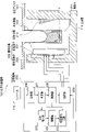
次に、本実施形態に係る化学分析装置100に装備されている攪拌機構109が、被攪拌物に対して、非接触で、検体と試薬を攪拌混合する場合について説明する。図2は、図1に示す化学分析装置100に装備されている攪拌機構109の具体的な構成の一例を示す図である。
Next, a case where the
図2に示すように、攪拌機構109は、圧電素子201、複数の超音波素子202(図4参照。202_1、202_2・・・202_10)、反射手段210、駆動装置220、などを備えている。駆動装置220は、波形発生器203、増幅器204、可変整合回路205、記憶部206、判定器207、制御器208、切替器209、などを備えている。
As shown in FIG. 2, the
圧電素子201は、恒温水211が満たされた恒温槽114の内壁に沿って、反応容器102の側面に対向するように設けられる。恒温槽114の一方の内壁に沿って、圧電素子201が設けられ、恒温槽114の他方の内壁に沿って、反射手段210が設けられている。圧電素子201と反射手段210との間には、反応容器102が配置されている。
The
圧電素子201は、圧電膜及び圧電膜の両面に形成される電極を含む。両電極間に電圧が印加されることで、圧電膜が振動し、所定周波数の超音波が、圧電素子201から反応容器102の側面へと照射される。
圧電素子201の側面で発生した超音波は、反射手段210で反射して、反応容器102へと供給される。
反応容器102へと供給される超音波は、反応容器102の側面から下方側に向かって照射され、反応容器102内の検体等の液を攪拌する。これにより、攪拌機構109は、反応容器102内の被攪拌対象物を非接触で攪拌することが可能になる。
The
The ultrasonic waves generated on the side surface of the
The ultrasonic waves supplied to the
圧電素子201は、駆動装置220から、振幅変調された波形の電圧が印加され、当該電圧(振幅の変化)に基づいて、反応容器102の側面に対して、超音波を照射する。
照射された超音波は、恒温槽114の壁中における恒温水211の内部を伝搬して、反応容器102に伝達され、反応容器102内に入射する。
一般に、液体中を伝搬してきた超音波が自由液面に達すると、液体は気体側に飛び出すような力(音響放射圧が主要因)が作用する。この際、本実施形態に係る化学分析装置100によれば、駆動装置220から圧電素子201へと、振幅変調された波形の電圧が印加される。このため、圧電素子201から反応容器102へと照射される超音波も、当該振幅変化に応じたものになる。
なお、反射手段210で反射され、反応容器102へと入射する超音波は、その進行方向において液面がない方向に設定される。
A voltage of an amplitude-modulated waveform is applied to the
The irradiated ultrasonic wave propagates inside the
Generally, when the ultrasonic waves propagating in the liquid reach the free liquid surface, the liquid is subjected to a force (mainly due to acoustic radiation pressure) that causes the liquid to jump out to the gas side. At this time, according to the chemical analyzer 100 according to the present embodiment, the voltage of the amplitude-modulated waveform is applied from the
The ultrasonic waves reflected by the reflecting means 210 and incident on the
複数の超音波素子202は、それぞれの超音波素子(202_1、202_2・・・202_10)が、独立に駆動できるように、セグメントがアレイ状に配置された構造を有している。
The plurality of
波形発生器203は、制御器208から入力される反応容器102で攪拌する液量(即ち、分注されている検体と試薬の量)、攪拌するタイミングに関する情報に基づいて、超音波波形を発生し、増幅器204へと出力する。
The
可変整合回路205は、判定結果に基づいて、波形発生器203と、駆動させる超音波素子202とのインピーダンスを整合する。
可変整合回路205は、液量に関する情報から反応容器102内に満たされている被測定液の液面高さを計算し、その液面を含めた最適な超音波照射領域を決定する。
可変整合回路205は、超音波素子202のインピーダンスと駆動装置220のインピーダンスとを整合する。これにより、駆動装置220への反射電力を低減させ、駆動装置220の耐久性を向上させることができる。
The
The
The
コンソール113からは検体情報が入力される。検体情報とは、攪拌条件の設定に必要な情報であり、例えば、検体の量に関する情報、粘性の情報、試薬の量に関する情報などが挙げられる。記憶部206は、この検体情報と攪拌情報との対応情報を記憶する。攪拌情報とは、攪拌に際して駆動させる超音波素子202の位置及び数等の情報である。
このように記憶部206を備えることで、検体情報に対して適切な攪拌条件を記憶することができる。
Sample information is input from the
By providing the
判定器207は、超音波の伝搬する高さが超音波素子202の高さ以下の分解能で調整されるように、複数の超音波素子202の中から、駆動させる超音波素子の位置及び数を記憶部206に記憶された対応情報に基づいて判定する。判定器207は、この判定結果を伝送情報として、制御器208へと出力する。
このように記憶部206を照合することで、判定器207は、判定の度に攪拌条件の算出を行わずとも、攪拌条件の判定ができるようになる。
The
By collating the
制御器208は、判定器207から入力される伝送情報に基づいて、制御信号を生成し、波形発生器203、可変整合回路205、切替器209、へと出力する。
The
切替器209は、制御器208から入力される制御信号に基づいて、圧電素子201の駆動する超音波素子202をON/OFF制御する。
切替器209は、複数の超音波素子202の中から、超音波照射領域に対応する超音波素子(駆動させる超音波素子)を選択する。これにより、所定の超音波素子が駆動する。
The
The
≪超音波攪拌原理≫
次に、図3及び図4を参照して、超音波攪拌原理について簡単に説明する。
図3は比較例の化学分析装置に係る超音波攪拌原理を説明するための断面図であり、
図4は本実施形態の化学分析装置100に係る超音波攪拌原理を説明するための断面図である。
まず、比較例の化学分析装置に係る超音波攪拌原理について説明する。
≪Ultrasonic stirring principle≫
Next, the ultrasonic stirring principle will be briefly described with reference to FIGS. 3 and 4.
FIG. 3 is a cross-sectional view for explaining the principle of ultrasonic stirring according to the chemical analyzer of the comparative example.
FIG. 4 is a cross-sectional view for explaining the ultrasonic stirring principle according to the chemical analyzer 100 of the present embodiment.
First, the ultrasonic stirring principle related to the chemical analyzer of the comparative example will be described.
比較例では、検体の気液界面に超音波が伝搬するように、複数の超音波素子の組み合わせを選択していた。使用素子の数は、駆動回路から使用素子群へのエネルギー伝達が一定となるように、一定数の素子が選択されている。そのため、超音波が伝搬する高さ分解能は、超音波素子の素子幅に依存している。 In the comparative example, a combination of a plurality of ultrasonic elements was selected so that the ultrasonic waves propagated to the gas-liquid interface of the sample. As for the number of elements used, a certain number of elements are selected so that the energy transfer from the drive circuit to the group of elements used is constant. Therefore, the height resolution at which the ultrasonic wave propagates depends on the element width of the ultrasonic element.
例えば、図3(a)に示すように、検体302Aの液量が所定量を満たす場合、比較例の化学分析装置は、圧電素子201における超音波素子202_5、202_6、202_7を駆動させる。この場合、超音波Xによる音響流303Aは、検体302Aの気液界面の位置と一致する。即ち、検体302Aの気液界面の位置に、音響流303Aが発生するように、超音波素子202_5、202_6、202_7は、制御される。
For example, as shown in FIG. 3A, when the liquid volume of the
例えば、図3(b)に示すように、検体302Bの液量が検体302Aの液量より増加する場合、比較例の化学分析装置は、圧電素子201における超音波素子202_4、202_5、202_6を駆動させる。この場合、超音波Xにより発生した音響流303Bは、検体302Bの気液界面の位置と一致する。即ち、検体302Bの気液界面の位置に、音響流303Bが発生するように、超音波素子202_4、202_5、202_6は、制御される。
For example, as shown in FIG. 3B, when the liquid volume of the
例えば、図3(c)に示すように、検体302Cの液量が検体302Bの液量より増加する場合、比較例の化学分析装置は、圧電素子201における超音波素子202_3、202_4、202_5を駆動させる。この場合、超音波Xにより発生した音響流303Cは、検体302Cの気液界面の位置と一致する。即ち、検体302Cの気液界面の位置に、音響流303Cが発生するように、超音波素子202_3、202_4、202_5は、制御される。
For example, as shown in FIG. 3C, when the liquid volume of the
即ち、比較例の化学分析装置は、超音波Xにより音響流303A~303Cを発生させる位置を、複数の超音波素子を、決められた個数で連続的に駆動させることで制御している。つまり、比較例の化学分析装置は、超音波素子のインピーダンスと駆動装置のインピーダンスとを整合させて、発生させる超音波Xを安定化させるため、駆動させる超音波素子の個数を一定とすることしかできない。従って、比較例の化学分析装置では、一定数の超音波素子の組合せ位置を制御する方法で、検体と試薬とを攪拌しているため、超音波素子の高さ以下の分解能で、超音波及び音響流の発生位置を制御することが困難であるという問題が生じている。
That is, the chemical analyzer of the comparative example controls the position where the
次に、本実施形態の化学分析装置100に係る超音波攪拌原理について説明する。図4は、本実施形態の化学分析装置100に係る超音波攪拌原理を説明するための断面図である。 Next, the ultrasonic stirring principle according to the chemical analyzer 100 of the present embodiment will be described. FIG. 4 is a cross-sectional view for explaining the ultrasonic stirring principle according to the chemical analyzer 100 of the present embodiment.
本実施形態の化学分析装置100は、超音波素子の高さ以下の分解能で超音波が伝搬する高さを調整するために、判定器と可変整合回路とを備える。判定器は、複数の超音波素子の中から駆動する素子の数と位置とを判定し、可変整合回路は、判定器による判定結果に応じて、インピーダンス整合を行う。 The chemical analyzer 100 of the present embodiment includes a determination device and a variable matching circuit in order to adjust the height at which the ultrasonic waves propagate with a resolution equal to or lower than the height of the ultrasonic element. The determination device determines the number and position of the elements to be driven from among the plurality of ultrasonic elements, and the variable matching circuit performs impedance matching according to the determination result by the determination device.
例えば、図4(a)に示すように、検体402Aの液量が所定量を満たす場合、化学分析装置100は、圧電素子201における超音波素子202_5、202_6、202_7を駆動させる。この場合、超音波Xによる音響流403Aは、検体402Aの気液界面の位置と一致する。即ち、検体402Aの気液界面の位置に、音響流403Aが発生するように、超音波素子202_5、202_6、202_7は、制御される。
For example, as shown in FIG. 4A, when the liquid amount of the
例えば、図4(b)に示すように、検体402Bの液量が検体402Aの液量より僅かに増加する場合、化学分析装置100は、圧電素子201における超音波素子202_4、202_5、202_6、202_7を駆動させる。この場合、超音波Xにより発生した音響流403Bは、検体402Bの気液界面の位置と一致する。
即ち、超音波X及び音響流403Bの発生位置は、超音波素子の高さ以下の分解能で制御され、図4(b)から、音響流403Bの発生位置は、検体402Bの気液界面の位置により近づいていることがわかる。図4(b)では、図4(a)より更に、高い分解能で、超音波X及び音響流の発生位置を制御することができることがわかる。
つまり、化学分析装置100は、超音波素子のインピーダンスと駆動装置のインピーダンスとを任意に整合させて、超音波素子202_4、202_5、202_6、202_7を、駆動制御することができる。
For example, as shown in FIG. 4B, when the liquid volume of the
That is, the generation position of the ultrasonic wave X and the
That is, the chemical analyzer 100 can arbitrarily match the impedance of the ultrasonic element and the impedance of the driving device to drive and control the ultrasonic elements 202_4, 202_5, 202_6, 202_7.
例えば、図4(c)に示すように、検体402Cの液量が検体402Aの液量より僅かに減少する場合、化学分析装置100は、圧電素子201における超音波素子202_4、202_5、202_6、202_8を駆動させる。この場合、超音波Xにより発生した音響流403Cは、検体402Cの気液界面の位置と一致する。
即ち、超音波X及び音響流403Cの発生位置は、超音波素子の高さ以下の分解能で制御され、図4(c)から、音響流403Bの発生位置は、検体402Bの気液界面の位置により近づいていることがわかる。図4(c)では、図4(b)よりも更に、高い分解能で、超音波X及び音響流の発生位置を制御することができることがわかる。
つまり、化学分析装置100は、超音波素子のインピーダンスと駆動装置のインピーダンスとを任意に整合させて、超音波素子202_4、202_5、202_6、202_8を、駆動制御することができる。
For example, as shown in FIG. 4C, when the liquid volume of the
That is, the generation position of the ultrasonic wave X and the
That is, the chemical analyzer 100 can arbitrarily match the impedance of the ultrasonic element and the impedance of the driving device to drive and control the ultrasonic elements 202_4, 202_5, 202_6, 202_8.
即ち、化学分析装置100は、超音波Xにより音響流403A~403Cを発生させる位置を、複数の超音波素子を、任意の個数で不連続的に駆動させることで制御できる。つまり、化学分析装置100は、超音波素子のインピーダンスと駆動装置のインピーダンスとを任意に整合させて、その都度、駆動させる超音波素子の位置や個数を、選択することができる。
従って、化学分析装置100は、駆動させる超音波素子の位置や個数を任意に制御する方法で、検体と試薬とを攪拌し、超音波素子の高さ以下の分解能で、超音波及び音響流の発生位置を制御することができる。超音波素子の高さ設定の精度を1つの超音波素子の高さ以下にすることで、検体と試薬の攪拌において、十分な旋回流を得て攪拌作用の向上を図ることが可能になる。
That is, the chemical analyzer 100 can control the positions where the
Therefore, the chemical analyzer 100 agitates the sample and the reagent by a method of arbitrarily controlling the position and the number of the ultrasonic elements to be driven, and has a resolution equal to or lower than the height of the ultrasonic elements, and the ultrasonic waves and the acoustic flow. The generation position can be controlled. By setting the height setting accuracy of the ultrasonic element to be equal to or less than the height of one ultrasonic element, it is possible to obtain a sufficient swirling flow and improve the stirring action in stirring the sample and the reagent.
本実施形態に係る化学分析装置100によれば、判定器が、複数の超音波素子の中から、駆動させる超音波素子の位置及び数を判定し、可変整合回路が、判定結果に基づいて、インピーダンス整合を行う。これにより、超音波素子の高さ以下の分解能で、超音波が伝搬する高さを調整することができる。これにより、超音波及び音響流を安定的に発生させることができるため、検体と試薬の攪拌性能を向上させた化学分析装置100を実現できる。 According to the chemical analyzer 100 according to the present embodiment, the determination device determines the position and number of the ultrasonic elements to be driven from among the plurality of ultrasonic elements, and the variable matching circuit determines the position and number of the ultrasonic elements to be driven based on the determination result. Perform impedance matching. As a result, the height at which the ultrasonic wave propagates can be adjusted with a resolution equal to or lower than the height of the ultrasonic element. As a result, ultrasonic waves and acoustic flows can be stably generated, so that the chemical analyzer 100 with improved stirring performance between the sample and the reagent can be realized.
≪第2実施形態≫
図5を参照して、第2実施形態に係る化学分析装置100Aの構成について、説明する。
<< Second Embodiment >>
The configuration of the chemical analyzer 100A according to the second embodiment will be described with reference to FIG.
第1実施形態に係る化学分析装置100が第2実施形態に係る化学分析装置100Aと異なる点は、第1実施形態に係る化学分析装置100では、可変整合回路205が、駆動装置220の内部に備えられているのに対して、第2実施形態に係る化学分析装置100Aでは、可変整合回路205Aが、駆動装置220の外部に備えられている点である。
The difference between the chemical analyzer 100 according to the first embodiment and the chemical analyzer 100A according to the second embodiment is that in the chemical analyzer 100 according to the first embodiment, the
可変整合回路205Aは、駆動装置220と圧電素子201との間に設けられる。可変整合回路205Aは、駆動装置220のインピーダンスと圧電素子201のインピーダンスとを整合する。可変整合回路205Aは、駆動周波数で電気インピーダンスが整合するように、判定器207によって判定された情報に基づいて、制御器208から制御信号を得て、制御器208からの伝達信号で設定される。
The
可変整合回路205Aは、例えば、可変抵抗、可変コンデンサ、可変コイル、などから構成される。可変整合回路205Aは、LPF(Low-pass filter)型、HPF(High-pass filter)型、T型、π型、または、それらを組合せた型で構成されてもよい。また、可変整合回路205Aは、トランス型や伝送線路型の整合回路でもよい。
The
以上説明したように、可変整合回路205Aが、超音波攪拌機構に備えられる場合でも、第1実施形態と同様に、超音波の伝搬及び音響流の発生の高さを、より液面付近に設定することができるため、検体と試薬の攪拌性能を向上させる化学分析装置を提供することできる。
As described above, even when the
なお、本発明は、以上に説明した実施形態および変形例に限定されるものではなく、さらに、様々な変形例が含まれる。例えば、前記した実施形態および変形例は、本発明を分かりやすく説明するために詳細に説明したものであり、必ずしも説明した全ての構成を備えるものに限定されるものではない。また、ある実施形態や変形例の構成の一部を、他の実施形態や変形例の構成に置き換えることが可能であり、また、ある実施形態や変形例の構成に他の実施形態や変形例の構成を加えることも可能である。また、各実施形態や変形例の構成の一部について、他の実施形態や変形例に含まれる構成を追加・削除・置換することも可能である。 The present invention is not limited to the embodiments and modifications described above, and further includes various modifications. For example, the above-described embodiments and modifications have been described in detail in order to explain the present invention in an easy-to-understand manner, and are not necessarily limited to those having all the described configurations. Further, it is possible to replace a part of the configuration of a certain embodiment or modification with the configuration of another embodiment or modification, and the configuration of a certain embodiment or modification can be replaced with another embodiment or modification. It is also possible to add the configuration of. Further, it is also possible to add / delete / replace the configuration included in other embodiments or modifications with respect to a part of the configurations of each embodiment or modification.
100 化学分析装置
202 超音波素子
203 波形発生器
206 記憶部
205,205A 可変整合回路
207 判定器
209 切替器
100
Claims (5)
超音波波形を発生する波形発生器と、
前記複数の超音波素子の中から、駆動させる超音波素子の位置及び数を判定する判定器と、
判定結果に基づいて、前記波形発生器と前記駆動させる超音波素子とのインピーダンスを整合する可変整合回路と、
前記複数の超音波素子の中から、前記駆動させる超音波素子を選択する切替器と、を備え、
前記複数の超音波素子は、上下方向に配列され、
前記駆動させる超音波素子が前記切替器によって選択される際の複数のパターンの中には、駆動させない一つの超音波素子が、前記駆動させる超音波素子によって、上下方向で挟まれている所定のパターンが含まれていることを特徴とする化学分析装置。 With multiple ultrasonic elements,
A waveform generator that generates ultrasonic waveforms and
A determination device that determines the position and number of ultrasonic elements to be driven from the plurality of ultrasonic elements.
A variable matching circuit that matches the impedance of the waveform generator and the ultrasonic element to be driven based on the determination result,
A switch for selecting the ultrasonic element to be driven from the plurality of ultrasonic elements is provided.
The plurality of ultrasonic elements are arranged in the vertical direction, and the plurality of ultrasonic elements are arranged in the vertical direction.
In the plurality of patterns when the driven ultrasonic element is selected by the switch, one non -driven ultrasonic element is sandwiched in the vertical direction by the driven ultrasonic element. A chemical analyzer characterized by containing a predetermined pattern.
を更に備えることを特徴とする請求項1に記載の化学分析装置。 The chemical analyzer according to claim 1, further comprising a storage unit that stores information on the amount and viscosity of the reaction solution, the position of the ultrasonic element to be driven, and the number of ultrasonic elements to be driven.
検体情報と前記記憶部に記憶される情報とを照合して、前記複数の超音波素子の中から、前記駆動させる超音波素子の位置及び数を判定する、
ことを特徴とする請求項2に記載の化学分析装置。 The judgment device is
By collating the sample information with the information stored in the storage unit, the position and number of the ultrasonic element to be driven are determined from the plurality of ultrasonic elements.
The chemical analyzer according to claim 2.
前記複数の超音波素子の駆動周波数に基づいて、前記インピーダンスを整合する、
ことを特徴とする請求項1乃至請求項3のいずれか一項に記載の化学分析装置。 The variable matching circuit is
Matching the impedance based on the drive frequencies of the plurality of ultrasonic elements.
The chemical analyzer according to any one of claims 1 to 3, wherein the chemical analyzer is characterized by the above.
超音波の伝搬する高さが、前記超音波素子の高さ以下の分解能で調整されるように、前記複数の超音波素子の中から、前記駆動させる超音波素子の位置及び数を判定する、
ことを特徴とする請求項1乃至請求項4のいずれか一項に記載の化学分析装置。 The judgment device is
The position and number of the driven ultrasonic elements are determined from the plurality of ultrasonic elements so that the height at which the ultrasonic waves propagate is adjusted with a resolution equal to or lower than the height of the ultrasonic elements.
The chemical analyzer according to any one of claims 1 to 4, wherein the chemical analyzer is characterized by the above.
Priority Applications (5)
| Application Number | Priority Date | Filing Date | Title |
|---|---|---|---|
| JP2018123943A JP7061525B2 (en) | 2018-06-29 | 2018-06-29 | Chemical analyzer |
| US17/255,714 US20210270707A1 (en) | 2018-06-29 | 2019-05-13 | Chemical Analysis Device |
| CN201980028551.XA CN112041685A (en) | 2018-06-29 | 2019-05-13 | Chemical analysis apparatus |
| EP19825262.9A EP3816631B1 (en) | 2018-06-29 | 2019-05-13 | Chemical analysis device |
| PCT/JP2019/018864 WO2020003769A1 (en) | 2018-06-29 | 2019-05-13 | Chemical analysis device |
Applications Claiming Priority (1)
| Application Number | Priority Date | Filing Date | Title |
|---|---|---|---|
| JP2018123943A JP7061525B2 (en) | 2018-06-29 | 2018-06-29 | Chemical analyzer |
Publications (2)
| Publication Number | Publication Date |
|---|---|
| JP2020003378A JP2020003378A (en) | 2020-01-09 |
| JP7061525B2 true JP7061525B2 (en) | 2022-04-28 |
Family
ID=68986258
Family Applications (1)
| Application Number | Title | Priority Date | Filing Date |
|---|---|---|---|
| JP2018123943A Active JP7061525B2 (en) | 2018-06-29 | 2018-06-29 | Chemical analyzer |
Country Status (5)
| Country | Link |
|---|---|
| US (1) | US20210270707A1 (en) |
| EP (1) | EP3816631B1 (en) |
| JP (1) | JP7061525B2 (en) |
| CN (1) | CN112041685A (en) |
| WO (1) | WO2020003769A1 (en) |
Families Citing this family (3)
| Publication number | Priority date | Publication date | Assignee | Title |
|---|---|---|---|---|
| JP2022177414A (en) * | 2021-05-18 | 2022-12-01 | 株式会社日立ハイテク | Automatic chemical analyzer, and maintenance kit and maintenance method of the same |
| JP2023159560A (en) * | 2022-04-20 | 2023-11-01 | 株式会社日立ハイテク | Automatic analysis device |
| CN116381256A (en) * | 2023-02-28 | 2023-07-04 | 迈克医疗电子有限公司 | Sample analyzer |
Citations (4)
| Publication number | Priority date | Publication date | Assignee | Title |
|---|---|---|---|---|
| JP2003254981A (en) | 2002-03-01 | 2003-09-10 | Hitachi High-Technologies Corp | Chemical analyzer and chemical analysis method |
| JP2007108062A (en) | 2005-10-14 | 2007-04-26 | Olympus Corp | Agitator, container, and analyzer |
| WO2009005066A1 (en) | 2007-07-02 | 2009-01-08 | Olympus Corporation | Sound wave generation member, container, and analyzer |
| WO2016132798A1 (en) | 2015-02-19 | 2016-08-25 | 株式会社 日立ハイテクノロジーズ | Automated analysis device |
Family Cites Families (13)
| Publication number | Priority date | Publication date | Assignee | Title |
|---|---|---|---|---|
| JP3168886B2 (en) * | 1994-09-20 | 2001-05-21 | 株式会社日立製作所 | Chemical analyzer |
| JP3661076B2 (en) * | 1998-11-18 | 2005-06-15 | 株式会社日立製作所 | Chemical analyzer |
| JP3607557B2 (en) * | 2000-02-25 | 2005-01-05 | 株式会社日立製作所 | Automatic analyzer |
| JP4085230B2 (en) * | 2001-01-15 | 2008-05-14 | 株式会社日立製作所 | Stirring device and analyzer equipped with the stirring device |
| JP3746239B2 (en) | 2002-02-28 | 2006-02-15 | 株式会社日立ハイテクノロジーズ | Automatic analyzer |
| JP2007010345A (en) * | 2005-06-28 | 2007-01-18 | Olympus Corp | Stirrer, stirring method and analyzer equipped with stirrer |
| JP2007040843A (en) * | 2005-08-03 | 2007-02-15 | Hitachi High-Technologies Corp | Autoanalyzer |
| EP1947462A1 (en) * | 2005-10-14 | 2008-07-23 | Olympus Corporation | Stirring device, container, and analysis device |
| JP4406629B2 (en) | 2006-05-25 | 2010-02-03 | 株式会社日立ハイテクノロジーズ | Chemical analyzer |
| JP4887174B2 (en) * | 2007-02-19 | 2012-02-29 | 株式会社日立ハイテクノロジーズ | Automatic analyzer |
| JP2009002918A (en) | 2007-06-25 | 2009-01-08 | Olympus Corp | Sound wave generator, stirring device and automatic analyzer |
| JP5274188B2 (en) * | 2008-10-03 | 2013-08-28 | ベックマン コールター, インコーポレイテッド | Stirrer and analyzer |
| JP6224371B2 (en) | 2013-07-24 | 2017-11-01 | 株式会社日立ハイテクノロジーズ | Automatic analyzer |
-
2018
- 2018-06-29 JP JP2018123943A patent/JP7061525B2/en active Active
-
2019
- 2019-05-13 CN CN201980028551.XA patent/CN112041685A/en not_active Withdrawn
- 2019-05-13 EP EP19825262.9A patent/EP3816631B1/en active Active
- 2019-05-13 US US17/255,714 patent/US20210270707A1/en not_active Abandoned
- 2019-05-13 WO PCT/JP2019/018864 patent/WO2020003769A1/en active Application Filing
Patent Citations (4)
| Publication number | Priority date | Publication date | Assignee | Title |
|---|---|---|---|---|
| JP2003254981A (en) | 2002-03-01 | 2003-09-10 | Hitachi High-Technologies Corp | Chemical analyzer and chemical analysis method |
| JP2007108062A (en) | 2005-10-14 | 2007-04-26 | Olympus Corp | Agitator, container, and analyzer |
| WO2009005066A1 (en) | 2007-07-02 | 2009-01-08 | Olympus Corporation | Sound wave generation member, container, and analyzer |
| WO2016132798A1 (en) | 2015-02-19 | 2016-08-25 | 株式会社 日立ハイテクノロジーズ | Automated analysis device |
Also Published As
| Publication number | Publication date |
|---|---|
| EP3816631A4 (en) | 2022-04-20 |
| JP2020003378A (en) | 2020-01-09 |
| CN112041685A (en) | 2020-12-04 |
| US20210270707A1 (en) | 2021-09-02 |
| WO2020003769A1 (en) | 2020-01-02 |
| EP3816631B1 (en) | 2024-03-13 |
| EP3816631A1 (en) | 2021-05-05 |
Similar Documents
| Publication | Publication Date | Title |
|---|---|---|
| JP3828818B2 (en) | Chemical analysis apparatus and chemical analysis method | |
| JP7061525B2 (en) | Chemical analyzer | |
| US7808631B2 (en) | Stirrer and analyzer | |
| JP2009025248A (en) | Automatic analyzer and dispensation method | |
| JP2007010345A (en) | Stirrer, stirring method and analyzer equipped with stirrer | |
| WO2007088673A1 (en) | Position detection device, position detection method, and analysis device | |
| WO2007108179A1 (en) | Stirring device and analyzing device | |
| JP6966337B2 (en) | Chemical analyzer and sonic stirring mechanism used in the chemical analyzer | |
| JP2007057318A (en) | Analyzer, feeder, stirring device and stirring method | |
| JP4406629B2 (en) | Chemical analyzer | |
| JP3607557B2 (en) | Automatic analyzer | |
| JP4085230B2 (en) | Stirring device and analyzer equipped with the stirring device | |
| JP6858096B2 (en) | Chemical analyzer | |
| JP6824064B2 (en) | Automatic analyzer | |
| JP2009002918A (en) | Sound wave generator, stirring device and automatic analyzer | |
| JP2007205816A (en) | Analyzer and photometric method of it | |
| JP2007232523A (en) | Stirrer and analyzer | |
| JP2008268078A (en) | Stirrer and autoanalyzer | |
| JP2007232521A (en) | Stirrer and analyzer | |
| WO2007097174A1 (en) | Agitator and analyzer | |
| JP2011141244A (en) | Analyzer | |
| JP3121829U (en) | Automatic analyzer | |
| JP2002071697A (en) | Automatic analyzer | |
| JP2008292314A (en) | Stirrer and auto-analyzer | |
| JP2007198796A (en) | Stirrer and analyzer |
Legal Events
| Date | Code | Title | Description |
|---|---|---|---|
| A621 | Written request for application examination |
Free format text: JAPANESE INTERMEDIATE CODE: A621 Effective date: 20210122 |
|
| A131 | Notification of reasons for refusal |
Free format text: JAPANESE INTERMEDIATE CODE: A131 Effective date: 20210803 |
|
| A521 | Request for written amendment filed |
Free format text: JAPANESE INTERMEDIATE CODE: A523 Effective date: 20210902 |
|
| A131 | Notification of reasons for refusal |
Free format text: JAPANESE INTERMEDIATE CODE: A131 Effective date: 20211207 |
|
| A521 | Request for written amendment filed |
Free format text: JAPANESE INTERMEDIATE CODE: A523 Effective date: 20220113 |
|
| TRDD | Decision of grant or rejection written | ||
| A01 | Written decision to grant a patent or to grant a registration (utility model) |
Free format text: JAPANESE INTERMEDIATE CODE: A01 Effective date: 20220405 |
|
| A61 | First payment of annual fees (during grant procedure) |
Free format text: JAPANESE INTERMEDIATE CODE: A61 Effective date: 20220418 |
|
| R150 | Certificate of patent or registration of utility model |
Ref document number: 7061525 Country of ref document: JP Free format text: JAPANESE INTERMEDIATE CODE: R150 |