JP2009025248A - Automatic analyzer and dispensation method - Google Patents
Automatic analyzer and dispensation method Download PDFInfo
- Publication number
- JP2009025248A JP2009025248A JP2007191305A JP2007191305A JP2009025248A JP 2009025248 A JP2009025248 A JP 2009025248A JP 2007191305 A JP2007191305 A JP 2007191305A JP 2007191305 A JP2007191305 A JP 2007191305A JP 2009025248 A JP2009025248 A JP 2009025248A
- Authority
- JP
- Japan
- Prior art keywords
- sample
- specimen
- dispensing
- container
- rack
- Prior art date
- Legal status (The legal status is an assumption and is not a legal conclusion. Google has not performed a legal analysis and makes no representation as to the accuracy of the status listed.)
- Pending
Links
Images


Classifications
-
- G—PHYSICS
- G01—MEASURING; TESTING
- G01N—INVESTIGATING OR ANALYSING MATERIALS BY DETERMINING THEIR CHEMICAL OR PHYSICAL PROPERTIES
- G01N35/00—Automatic analysis not limited to methods or materials provided for in any single one of groups G01N1/00 - G01N33/00; Handling materials therefor
- G01N35/02—Automatic analysis not limited to methods or materials provided for in any single one of groups G01N1/00 - G01N33/00; Handling materials therefor using a plurality of sample containers moved by a conveyor system past one or more treatment or analysis stations
- G01N35/04—Details of the conveyor system
-
- B—PERFORMING OPERATIONS; TRANSPORTING
- B01—PHYSICAL OR CHEMICAL PROCESSES OR APPARATUS IN GENERAL
- B01F—MIXING, e.g. DISSOLVING, EMULSIFYING OR DISPERSING
- B01F31/00—Mixers with shaking, oscillating, or vibrating mechanisms
- B01F31/80—Mixing by means of high-frequency vibrations above one kHz, e.g. ultrasonic vibrations
- B01F31/86—Mixing by means of high-frequency vibrations above one kHz, e.g. ultrasonic vibrations with vibration of the receptacle or part of it
-
- B—PERFORMING OPERATIONS; TRANSPORTING
- B01—PHYSICAL OR CHEMICAL PROCESSES OR APPARATUS IN GENERAL
- B01F—MIXING, e.g. DISSOLVING, EMULSIFYING OR DISPERSING
- B01F31/00—Mixers with shaking, oscillating, or vibrating mechanisms
- B01F31/80—Mixing by means of high-frequency vibrations above one kHz, e.g. ultrasonic vibrations
- B01F31/87—Mixing by means of high-frequency vibrations above one kHz, e.g. ultrasonic vibrations transmitting the vibratory energy by means of a fluid, e.g. by means of air shock waves
-
- B—PERFORMING OPERATIONS; TRANSPORTING
- B01—PHYSICAL OR CHEMICAL PROCESSES OR APPARATUS IN GENERAL
- B01F—MIXING, e.g. DISSOLVING, EMULSIFYING OR DISPERSING
- B01F33/00—Other mixers; Mixing plants; Combinations of mixers
- B01F33/80—Mixing plants; Combinations of mixers
- B01F33/85—Mixing plants with mixing receptacles or mixing tools that can be indexed into different working positions
-
- G—PHYSICS
- G01—MEASURING; TESTING
- G01N—INVESTIGATING OR ANALYSING MATERIALS BY DETERMINING THEIR CHEMICAL OR PHYSICAL PROPERTIES
- G01N35/00—Automatic analysis not limited to methods or materials provided for in any single one of groups G01N1/00 - G01N33/00; Handling materials therefor
- G01N2035/00465—Separating and mixing arrangements
- G01N2035/00524—Mixing by agitating sample carrier
-
- G—PHYSICS
- G01—MEASURING; TESTING
- G01N—INVESTIGATING OR ANALYSING MATERIALS BY DETERMINING THEIR CHEMICAL OR PHYSICAL PROPERTIES
- G01N35/00—Automatic analysis not limited to methods or materials provided for in any single one of groups G01N1/00 - G01N33/00; Handling materials therefor
- G01N2035/00465—Separating and mixing arrangements
- G01N2035/00534—Mixing by a special element, e.g. stirrer
- G01N2035/00554—Mixing by a special element, e.g. stirrer using ultrasound
Abstract
Description
本発明は、自動分析装置及び分注方法に関するものである。 The present invention relates to an automatic analyzer and a dispensing method.
従来、検体や試薬を分注する際に使用される自動分析装置の分注装置は、採取後の時間経過に伴う成分の沈降によって鉛直方向に濃度勾配が発生する検体、例えば、赤血球成分であるヘモグロビンA1c(HbA1c)を分析するため血液(全血)を分注する場合、検体容器中の血液の液面高さを検知し、赤血球の沈降を考慮した深さまで分注プローブの先端を潜り込ませて血液を分注していた(例えば、特許文献1参照)。 Conventionally, a dispensing device of an automatic analyzer used when dispensing a sample or a reagent is a sample in which a concentration gradient is generated in the vertical direction due to sedimentation of components with the passage of time after collection, for example, a red blood cell component When dispensing blood (whole blood) to analyze hemoglobin A1c (HbA1c), the level of the blood in the sample container is detected, and the tip of the dispensing probe is submerged to a depth that allows for red blood cell sedimentation. The blood was dispensed (see, for example, Patent Document 1).
ところで、成分の沈降を考慮して分注プローブの先端を検体中に潜り込ませると、分注装置は、分注プローブの先端を常に一定量液体試料中に潜り込ませる場合に比べて洗浄範囲が広がるため、プローブ洗浄の際の洗浄液量や洗浄に要する時間が増加するという問題があった。 By the way, if the tip of the dispensing probe is submerged in the specimen in consideration of the sedimentation of the component, the dispensing device expands the washing range as compared with the case where the tip of the dispensing probe is always submerged in the liquid sample. For this reason, there has been a problem that the amount of cleaning liquid and the time required for cleaning increase during probe cleaning.
本発明は、上記に鑑みてなされたものであって、沈降成分を含む検体であっても、一般の液体試料と同様に分注プローブの先端を一定量検体中に潜り込ませるだけで、常に一定濃度の検体を分注することが可能な自動分析装置及び分注方法を提供することを目的とする。 The present invention has been made in view of the above, and even for a specimen containing a sediment component, the tip of the dispensing probe is always kept constant by submerging the tip of the dispensing probe into the specimen in the same manner as a general liquid sample. An object of the present invention is to provide an automatic analyzer and a dispensing method capable of dispensing a sample having a concentration.
上述した課題を解決し、目的を達成するために、本発明の自動分析装置は、複数の異なる液体を攪拌して反応させ、反応液の光学的特性を測定して前記反応液を分析する自動分析装置であって、沈降成分を含む検体を保持する容器又は前記容器を配置するラックに設けた振動子と、前記ラックを分注位置へ搬送する搬送路に設けて前記振動子に電力を供給する電極とを有する攪拌手段を備え、前記攪拌手段は、前記ラックが前記搬送路に沿って前記分注位置へ搬送される間に前記電極から前記振動子に電力を供給し、前記容器に保持された前記沈降成分を含む検体を攪拌することを特徴とする。 In order to solve the above-described problems and achieve the object, the automatic analyzer of the present invention is an automatic analyzer that stirs and reacts a plurality of different liquids and measures the optical characteristics of the reaction liquid to analyze the reaction liquid. An analyzer, which is provided in a container for holding a specimen containing a sedimentation component or a rack in which the container is disposed, and a transport path for transporting the rack to a dispensing position to supply power to the vibrator And agitating means having an electrode for supplying power to the vibrator from the electrode while the rack is being conveyed along the conveying path to the dispensing position and being held in the container. The specimen containing the sedimented component is agitated.
また、本発明の自動分析装置の一態様は、上記の発明において、前記ラックを前記搬送路に設置後、前記検体を前記分注位置で分注するまでの間に前記検体を攪拌することを特徴とする。 In one aspect of the automatic analyzer of the present invention, in the above invention, the sample is agitated after the rack is installed in the transport path and before the sample is dispensed at the dispensing position. Features.
また、上述した課題を解決し、目的を達成するために、本発明の分注方法は、沈降成分を含む検体を分注する分注方法であって、前記沈降成分を含む検体を分注前に攪拌する攪拌工程を含むことを特徴とする。 In order to solve the above-described problems and achieve the object, the dispensing method of the present invention is a dispensing method for dispensing a specimen containing a precipitated component, and before dispensing the specimen containing the precipitated component. And a stirring step of stirring.
また、上述した課題を解決し、目的を達成するために、本発明の分注方法は、前記攪拌工程の前に、前記検体の上澄み液を分注する分注工程を含むことを特徴とする。 In order to solve the above-described problems and achieve the object, the dispensing method of the present invention includes a dispensing step of dispensing the supernatant of the specimen before the stirring step. .
本発明の自動分析装置は、ラックが搬送路に沿って分注位置へ搬送される間に攪拌手段の電極から振動子に電力を供給し、容器に保持された沈降成分を含む検体を攪拌し、本発明の分注方法は、沈降成分を含む検体を分注前に攪拌する攪拌工程を含んでいるので、沈降成分を含む検体であっても、一般の液体試料と同様に分注プローブの先端を常に一定量検体中に潜り込ませるだけで、常に一定濃度の検体を分注することができるという効果を奏する。 The automatic analyzer of the present invention stirs a specimen containing sedimentation components held in a container by supplying power to the vibrator from the electrode of the stirring means while the rack is transported to the dispensing position along the transport path. The dispensing method of the present invention includes an agitation step of agitating a specimen containing a sedimented component before dispensing. Therefore, even for a specimen containing a sedimented component, the dispensing probe is similar to a general liquid sample. It is possible to always dispense a specimen having a constant concentration by always letting the tip end into the specimen.
以下、本発明の自動分析装置及び分注方法にかかる実施の形態について、図面を参照しつつ詳細に説明する。図1は、本発明の自動分析装置を示す概略構成図である。図2は、自動分析装置の構成を示すブロック図である。図3は、自動分析装置の検体容器移送装置を拡大して検体攪拌部の配置を示す平面図である。 Hereinafter, embodiments of the automatic analyzer and the dispensing method of the present invention will be described in detail with reference to the drawings. FIG. 1 is a schematic configuration diagram showing an automatic analyzer of the present invention. FIG. 2 is a block diagram showing the configuration of the automatic analyzer. FIG. 3 is a plan view showing the arrangement of the sample agitating unit by enlarging the sample container transfer device of the automatic analyzer.
自動分析装置1は、図1及び図2に示すように、試薬テーブル2,3、反応テーブル4、検体容器移送装置8、検体分注装置11、検体攪拌部12(図3参照)、分析光学系13、洗浄装置14、攪拌装置15及び制御部17を備えている。
As shown in FIGS. 1 and 2, the
試薬テーブル2,3は、図1に示すように、それぞれ周方向に配置される複数の試薬容器2a,3aを保持し、駆動手段に回転されて試薬容器2a,3aを周方向に搬送する。
As shown in FIG. 1, the reagent tables 2 and 3 hold a plurality of
反応テーブル4は、図1に示すように、複数の反応容器5が周方向に沿って配列され、試薬テーブル2,3の駆動手段とは異なる駆動手段によって正転或いは逆転されて反応容器5を搬送する。反応テーブル4は、例えば、一周期で時計方向に(1周−1反応容器)/4周回転し、四周期で(1周−1反応容器)周回転する。 As shown in FIG. 1, the reaction table 4 has a plurality of reaction vessels 5 arranged in the circumferential direction, and is rotated forward or reverse by a driving means different from the driving means of the reagent tables 2 and 3 so that the reaction container 5 Transport. The reaction table 4 rotates, for example, clockwise in one cycle (1 turn-1 reaction vessel) / 4 turns and in 4 cycles (1 turn-1 reaction vessel).
反応容器5は、容量が数nL〜数百μLと微量な容器であり、分析光学系13の発光部13aから出射された分析光に含まれる光の80%以上を透過する透明素材、例えば、耐熱ガラスを含むガラス,環状オレフィンやポリスチレン等の合成樹脂が使用される。反応容器5は、液体を保持する部分の水平断面が四角形に成形され、上部に開口を有する四角筒形状のキュベットである。反応容器5は、反応テーブル4の近傍に設けた試薬分注装置6,7によって試薬テーブル2,3の試薬容器2a,3aから試薬が分注される。
The reaction container 5 is a very small container with a capacity of several nL to several hundred μL, and is a transparent material that transmits 80% or more of the light contained in the analysis light emitted from the
ここで、試薬分注装置6,7は、それぞれ水平面内を矢印方向に回動するアーム6a,7aに試薬を分注するプローブ6b,7bが設けられ、洗浄水によってプローブ6b,7bを洗浄する洗浄手段を有している。
Here, the reagent dispensing
検体容器移送装置8は、図3に示すように、配列した複数のラック9を矢印方向又は逆方向に沿って1つずつ移送するベルトコンベア等の移送手段である。検体容器移送装置8は、ラック9を横方向に搬送する横搬送路8aと縦方向に搬送する縦搬送路8bとを有し、横搬送路8aのセット位置Ps(図3参照)に供給されたラック9を歩進させながら横搬送路8aと縦搬送路8bに沿って矢印で示す方向へ移送する。ラック9は、検体を収容した複数の検体容器10を凹部9a(図5参照)に保持しており、側壁9bの下部には長手方向に沿って受電電極9cが複数設けられている。
As shown in FIG. 3, the sample
検体分注装置11は、検体容器移送装置8によって移送されるラック9の歩進が停止するごとに、検体容器移送装置8の搬送路上の分注位置Ppにある各検体容器10から反応容器5に検体を分注する。検体分注装置11は、水平方向に回動する駆動アーム11aとプローブ11bと、液面検知手段とを有する他、洗浄水によってプローブ11bを洗浄する洗浄手段(不図示)とを備えている。
Each time the step of the
検体攪拌部12は、沈降成分を含む検体を攪拌する攪拌手段であり、図3に示すように、ラック9のセット位置Psから分注位置Ppへとラック9を歩進させながら縦方向に搬送する検体容器移送装置8の一方の縦搬送路8bに沿って配置され、給電電極12aと検体容器10の底部に設けた振動子12b(図5参照)とを有している。
The
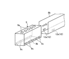
給電電極12aは、図4に示すように、検体容器移送装置8の縦搬送路8bの両側に設けられている。振動子12bは、受電電極9cが給電電極12aと接触して給電される駆動電力を、図5に示すように、ラック9の凹部9a底部に設けた給電電極9dを介して受電することによって駆動され、検体容器10内の沈降成分を含む検体Sを非接触で攪拌する。ここで、給電電極12aは、両側に代えて、縦搬送路8bの片側に2つ設けてもよい。
As shown in FIG. 4, the
振動子12bは、例えば、ニオブ酸リチウム(LiNbO3)等からなる圧電基板の一方の面に複数の櫛歯状電極(IDT)を形成した表面弾性波素子が使用され、表面弾性波やバルク波によって検体容器10が保持した液体を攪拌する。振動子12bは、検体容器10下部の湾曲部を経て水平な平面となった底部に設けられる。ここで、図5を含め、以下に使用するラック9の断面図においては、図面の見易さを優先してハッチングを省略している。
As the
分析光学系13は、試薬と検体とが反応した反応容器5内の液体を分析するための分析光を出射するもので、図1に示すように、発光部13a,分光部13b及び受光部13cを有している。発光部13aから出射された分析光は、反応容器5内の液体を透過し、分光部13bと対向する位置に設けた受光部13cによって受光される。受光部13cは、制御部17と接続され、受光した分析光の光量信号を制御部17へ出力する。
The analysis
洗浄装置14は、ノズル14aによって反応容器5内の液体を吸引して排出した後、ノズル14aから洗剤や洗浄水等の洗浄液を注入し、吸引する動作を複数回繰り返すことにより、分析光学系13による測光が終了した反応容器5内を洗浄する。
The
制御部17は、例えば、マイクロコンピュータ等が使用され、図1及び図2に示すように、自動分析装置1の各構成部と接続されてこれらの作動を制御すると共に、発光部13aの出射光量と受光部13cが受光した光量に基づく反応容器5内の液体の吸光度に基づいて検体の成分濃度等を分析する。また、制御部17は、ホストコンピュータから入力される攪拌を要する検体容器10の情報と、検体容器移送装置8から入力されるラック9の位置情報から検体容器移送装置8の搬送路に沿った攪拌を要する検体容器10の位置を把握し、攪拌を要する検体容器10に対応する給電電極12aに駆動電力を給電するように検体攪拌部12を制御する。
For example, a microcomputer or the like is used as the
制御部17は、キーボード等の入力部18から入力される分析指令に基づいて自動分析装置1の各構成部の作動を制御しながら分析動作を実行させると共に、分析結果や警告情報の他、入力部18から入力される表示指令に基づく各種情報等をディスプレイパネル等の表示部19に表示する。この他、制御部17は、検体容器10の底部に設けた振動子12bからの駆動電力の反射をもとに振動子12bの接触不良等を含む異常を検知し、検知した異常の回数を記憶する。更に、制御部17は、プローブ11bを検体中に深く潜り込ませて通常の検体を分注する従来の分注方法と、沈降成分を含む検体を分注前に攪拌する本発明の分注方法を用いた場合にプローブ11bを検体中に浅く潜り込ませる場合の検体分注装置11に関する分注動作並びにプローブ11bの洗浄動作の設定を変更する。
The
攪拌装置15は、反応容器5に取り付けた表面弾性波素子15cを駆動して発生する可聴周波数を超える周波数の音波である超音波によって反応容器5に保持された液体を攪拌する。攪拌装置15は、数MHz〜数百MHz程度の高周波交流電源から供給される電力を表面弾性波素子15cに送電する送電体15aと、送電体15aと電気端子との反応テーブル4の周方向並びに半径方向における相対配置を調整する配置決定部材15bとを有している。
The
以上のように構成される自動分析装置1は、制御部17の制御の下に作動し、回転する反応テーブル4によって周方向に沿って搬送されてくる複数の反応容器5に試薬分注装置6,7が試薬容器2a,3aから試薬を順次分注する。試薬が分注された反応容器5は、検体分注装置11によってラック9に保持された複数の検体容器10から検体が順次分注される。
The
そして、試薬と検体が分注された反応容器5は、反応テーブル4が停止する都度、攪拌装置15によって順次攪拌されて試薬と検体とが反応し、反応テーブル4が再び回転したときに分析光学系13を通過する。このとき、反応容器5内の反応液は、受光部13cで測光され、制御部17によって成分濃度等が分析される。そして、反応液の測光が終了した反応容器5は、洗浄装置14によって洗浄された後、再度検体の分析に使用される。
Then, each time the reaction table 4 stops, the reaction container 5 into which the reagent and the sample have been dispensed is sequentially agitated by the
このとき、自動分析装置1は、検体容器移送装置8の搬送路に配置された検体攪拌部12を備えている。このため、検体容器移送装置8の搬送路に沿って搬送されてくるラック9に保持された複数の検体容器10は、ラック9の歩進に伴って側壁9b下部の受電電極9cが給電電極12aと順次接触する。この結果、沈降成分を含む検体を保持する検体容器10が検体攪拌部12に到達すると、制御部17の制御の下に送電される駆動電力を振動子12bが給電電極9dを介して受電し、これにより振動子12bが発する超音波によって生ずる音響流によって沈降成分を含む検体が均一に攪拌される。
At this time, the
このとき、制御部17の制御の下に実行される検体の分注方法を図6に示すフローチャートを参照して以下に説明する。
At this time, the sample dispensing method executed under the control of the
先ず、制御部17は、沈降成分を含む検体を保持した攪拌を要する検体容器10が検体攪拌部12に到達したか否かを判定する(ステップS100)。検体容器10の位置は、ホストコンピュータから制御部17に入力される沈降成分を含む検体を保持した検体容器10の情報をもとに検体容器移送装置8の搬送路に沿った検体容器10の歩進位置として検出し、この検出した検体容器10の歩進位置が検体攪拌部12の位置であるか否かを判定する。
First, the
検出した検体容器10の歩進位置が検体攪拌部12の位置でない場合(ステップS100,No)、制御部17は、ステップS100に戻って検体容器10が検体攪拌部12に到達したか否かを判定する。一方、検出した検体容器10の歩進位置が検体攪拌部12の場合(ステップS100,Yes)、制御部17は、検体容器10が保持した沈降成分を含む検体の攪拌を開始する(ステップS102)。このとき、攪拌は、検体容器10が検体攪拌部12に到達したことを検出後、検体容器移送装置8による歩進を停止させた後、攪拌を要する検体容器10に対応する給電電極12aに駆動電力を給電するように制御部17が電力供給部を制御することによって実行される。
If the detected advance position of the
次いで、制御部17は、攪拌開始後に異常を検知したか否かを判定する(ステップS104)。攪拌開始後に受電電極9cと給電電極12aとの接触不良等の異常を検知しなかった場合(ステップS104,No)、検体容器10は保持した沈降成分を含む検体が検体攪拌部12によって均一に攪拌されている。このため、制御部17は、給電電極12aへの駆動電力の給電を停止し、検体の攪拌を終了する(ステップS106)。
Next, the
その後、制御部17は、検体が均一に攪拌された検体容器10を分注位置へ歩進させる(ステップS108)。そして、制御部17は、均一に攪拌された検体を分注装置11によって検体容器10から反応容器5に分注する(ステップS110)。このとき、検体は予め均一に攪拌されているので、分注装置11は、プローブ11bの下端を検体中に一定量潜り込ませるだけで、常に一定濃度の検体を分注することができる。
Thereafter, the
次に、制御部17は、分注装置11のプローブ11bを前記洗浄手段によって洗浄する(ステップS112)。このとき、プローブ11bは、下端が検体中に僅かしか潜り込んでいないので、前記洗浄手段が洗浄に使用する洗浄水は少量で済む。次いで、制御部17は、ホストコンピュータから制御部17に入力される沈降成分を含む検体を保持した検体容器10の情報をもとに攪拌を要する総ての検体容器10の攪拌が終了したか否かを判定する(ステップS114)。
Next, the
総ての検体容器10の攪拌が終了していない場合(ステップS114,No)、制御部17は、ステップS100に戻る。総ての検体容器10の攪拌が終了した場合(ステップS114,Yes)、制御部17は、沈降成分を含む検体を保持した検体容器10からの検体の分注方法を終了する。
When stirring of all the
一方、攪拌開始後に受電電極9cと給電電極12aとの接触不良等の異常を検知した場合(ステップS104,Yes)、制御部17は、異常の検知が1回目か否かを判定する(ステップS116)。検知した異常の回数が1回目の場合(ステップS116,Yes)、制御部17は、給電電極12aへの駆動電力の給電停止と共に、検体容器移送装置8による検体容器10の当該歩進位置への再停止を実行させる(S118)。その後、制御部17は、ステップS102に戻って攪拌を再開する。このとき、制御部17は、ホストコンピュータに接触不良等の異常を検知した旨を通知する。
On the other hand, when an abnormality such as poor contact between the
ここで、給電電極9dと振動子12bとの接触不良は、検体容器10を凹部9aへ設置し直すことによって解消することができる。また、ここで検出する異常には受電電極9cと給電電極12aとの接触不良以外に、例えば、振動子12bの故障があるが、この場合には検体容器10を交換する。但し、変形例1で説明するように、振動子12bをラック9側に設ける場合には、攪拌対象の検体容器10を配置する凹部9aの位置を変更する。
Here, the contact failure between the feeding
一方、検知した異常の回数が1回目でない場合(ステップS116,No)、制御部17は、給電電極12aへの駆動電力の給電を停止し、検体の攪拌を終了する(ステップS120)。その後、制御部17は、検体容器10を分注位置へ歩進させる(ステップS122)。そして、制御部17は、検体分注装置11の分注動作の設定を変更する(ステップS124)。
On the other hand, when the detected number of abnormalities is not the first time (step S116, No), the
次に、制御部17は、分注装置11によって検体容器10から反応容器5に検体を分注する(ステップS126)。このとき、検体分注装置11は、制御部17の制御の下に、検体容器10が保持する検体中の沈降成分が沈降した状態で検体を分注する場合と同様に、プローブ11bを検体容器10の検体中に深く潜り込ませて検体を分注する。
Next, the
次いで、制御部17は、プローブ11bの洗浄動作の設定を変更する(ステップS128)。そして、制御部17は、変更された洗浄動作によって検体分注後のプローブ11bを洗浄する(ステップS130)。このとき、プローブ11bを洗浄する前記洗浄手段は、検体容器10が保持する検体中の沈降成分が沈降した状態で検体を分注したプローブ11bを洗浄する場合と同様に、検体中に深く潜り込んだプローブ11bの部分を十分に洗浄する。その後、制御部17は、ステップS114にスキップしてステップS114以降のステップを実行する。
Next, the
以上の説明で明らかなように、検体容器10に保持された沈降成分を含む検体は、図3に示すように、検体容器移送装置8の搬送路上の分注位置Ppで分注される前に、検体攪拌部12において振動子12bが発する超音波によって生ずる音響流によって均一に攪拌される。このため、検体分注装置11は、沈降成分を含む検体であっても通常の他の検体と同様に、プローブ11bの先端を常に一定量検体中に潜り込ませるだけで、均一に攪拌された検体を検体容器10から反応容器5に分注することができる。この結果、検体分注装置11は、沈降成分を含む検体であってもプローブ11bの先端を検体中に深く潜り込ませる必要がないので、通常の検体を分注した場合と同様の洗浄を行うだけでよく、常に同一の分注動作と洗浄動作をするだけでよいので、作動の制御が容易になる。
As is clear from the above description, the specimen containing the sediment component held in the
ここで、検体攪拌部12は、沈降成分を含む検体を保持した検体容器10をセットしたラック9をセット位置Psに配置した後、配置したラック9が検体容器移送装置8によって分注位置Ppへ移送されるまでに沈降成分の沈降による分析結果への影響を与えない時間(例えば、全血成分では15〜30分)であれば、セット位置Psと分注位置Ppの間のどこに設けてもよい。例えば、図7に示すように、第2攪拌部P2〜第9攪拌部P9の少なくとも1箇所に配置する。
Here, the
これらの攪拌部は、検体容器移送装置8の縦搬送路8bに沿って配置され、図3に示した検体攪拌部12と同じ固定式の攪拌部である。このとき、例えば、第2攪拌部P2は、図8(図9)に示すように、縦搬送路8bの底面に給電電極12aを設ける。そして、検体容器10を保持するラック9は、給電電極12aと対応する底面に複数の受電電極9cを設ける。ここで、給電電極12aは、図9に示すように、縦搬送路8bの両側に複数設け、電力を供給する給電電極12aを変更することによってラック9の所望位置に保持された検体容器10の検体を攪拌するようにしてもよい。この場合、給電電極12aは、縦搬送路8bの底面に複数設けてもよい。また、振動子12bは、検体容器10の底部であれば、底面付近の側面に設けてもよい。
These stirring units are arranged along the
更に、横搬送路8aにおいても攪拌を行う場合には、図10に示すように、横搬送路8aに第1攪拌部P1や第5攪拌部P5を設ける。このとき、例えば、第1攪拌部P1は、検体容器移送装置8の横搬送路8aの下部に配置され、図11に示すように、リニアガイド16のレール16aに沿ってスライドするスライダ16bの上面に2つの給電電極12aが設けられた可動式の攪拌部であり、第5攪拌部P5も可動式の攪拌部である。この場合、ラック9は、給電電極12aを底面に設ける。
Furthermore, when stirring is performed also in the
上述のような構成とすることにより、検体容器移送装置8によって移送されるラック9は、図12及び図13に示すように、底面の受電電極9cが給電電極9dを介して給電電極12aと接触し、振動子12bが駆動電力を受電する。この結果、ラック9が保持した検体容器10は、振動子12bが発する超音波によって生ずる音響流によって沈降成分を含む検体Sが均一に非接触で攪拌される。
With the configuration as described above, the
このため、検体分注装置11は、一般の液体試料と同様にプローブ11bの先端を一定量検体中に潜り込ませるだけで、常に一定濃度の検体を分注することができる。また、検体攪拌部12は、振動子12bとして表面弾性波素子を使用していることから検体容器移送装置8に沿って配置することは、攪拌棒等の機械的攪拌手段を配置するのに比べて容易である。従って、検体攪拌部12の給電電極12aを設けることができれば、検体分注装置11は、構造上大きな改変をすることなく自動分析装置1に簡易に設けることができるという利点がある。
For this reason, the
ここで、検体分注装置11は、第9攪拌部P9において検体容器10に保持された血液の血漿成分を分注した後、検体容器10に保持された血液を攪拌し、均一に混合された全血を分注してもよい。このようにすると、1つの血液を異なる検査目的のために予め複数の容器に分割しておかなくとも、検体容器10に保持された血液を異なる検査目的に応じて複数の容器に分注することができる。
Here, the
ここで、異常の検知が2回目の場合、反応容器5に分注された検体を分析しても良好な結果が得られない場合が多い。このため、ステップS120以降の工程は省略してもよい。また、ステップS130は、ステップS126と同時に実行してもよい。 Here, when the abnormality is detected for the second time, a good result is often not obtained even if the sample dispensed in the reaction container 5 is analyzed. For this reason, you may abbreviate | omit the process after step S120. Further, step S130 may be executed simultaneously with step S126.
(変形例1)
ここで、検体攪拌部12は、振動子12bを検体容器10に設けるのに代えて、図14及び図15に示すように、振動子12bをラック9に形成した凹部9aの底部に設け、振動子12bが発生した超音波を、油,水又はゲル等からなる音響整合層Laoを介して検体容器10が保持した沈降成分を含む検体Sに伝搬させてもよい。このとき、ラック9は、図16に示すように、受電電極9cを側壁9bの下部に設け、検体容器移送装置8の縦搬送路8bの両側にラック9の搬送方向に所定間隔をおいて設けた複数の給電電極12aから給電するようにしてもよい。ここで、振動子12bの駆動周波数が低い場合には、音響整合層Laoは不要である。
(Modification 1)
Here, instead of providing the
(変形例2)
また、検体攪拌部12は、振動子12bとして表面弾性波素子に代えて厚み縦振動子を使用してもよい。この場合、厚み縦振動子を使用した振動子12bは、振幅が大きいことから、図17及び図18に示すように、検体容器10を保持する凹部9aの上部に支点となる突部9eを設けると共に、振動子12bと対向する位置には、振動子12bが検体容器10に付与する振動を受ける弾性体9fを設けておく。このように構成すると、凹部9aに保持された検体容器10は、振動子12bから振動を付与すると、突部9eを支点として下部が図18に矢印で示すように水平方向へ揺動し、保持した沈降成分を含む検体Sを均一に攪拌することができる。
(Modification 2)
In addition, the
ここで、検体攪拌部12は、振動子12bとして上述の表面弾性波素子や厚み縦振動子を含む電歪振動子の他に、磁歪振動子等を使用することができる。
Here, the
また、ラック9は、図19に示すように、受電電極9cを側壁9bの下部に設け、検体容器移送装置8の縦搬送路8bの両側にラック9の搬送方向に所定間隔をおいて設けた複数の給電電極12aから給電するようにしてもよい。
Further, as shown in FIG. 19, the
なお、上述の実施の形態の自動分析装置及び分注方法は、赤血球成分であるヘモグロビンA1cを分析するために検体として血液を分注する場合について説明した。しかし、本発明の自動分析装置及び分注方法は、採取後の時間経過に伴う沈降によって鉛直方向に濃度勾配が発生する沈降成分を含む検体であれば、血液等の検体に限定されるものではなく、例えば、髄液,胆汁,たん,粘液等の体液を含む検体や、懸濁態有機物等の沈降成分を含む河川水,湖沼水或いは海洋水等の検体にも使用可能である。また、本発明の自動分析装置及び分注方法は、コントロール血清等にも使用可能である。 In the above-described embodiment, the automatic analyzer and the dispensing method have described the case where blood is dispensed as a specimen in order to analyze hemoglobin A1c, which is an erythrocyte component. However, the automatic analyzer and the dispensing method of the present invention are not limited to specimens such as blood as long as they contain a sediment component that causes a concentration gradient in the vertical direction due to sedimentation over time after collection. For example, it can also be used for specimens containing body fluids such as cerebrospinal fluid, bile, sputum and mucus, and specimens such as river water, lake water or marine water containing sedimentation components such as suspended organic matter. The automatic analyzer and dispensing method of the present invention can also be used for control serum and the like.
一方、上述の実施の形態は、検体を保持する容器又は前記容器を配置するラックに設けた振動子を駆動することによって検体を攪拌する攪拌手段の場合について説明した。しかし、配置上のスペースを確保することができれば、検体を保持する容器又は前記容器を配置するラックを機械的に揺動させて検体を攪拌する攪拌手段を用いてもよい。 On the other hand, in the above-described embodiment, the case of the agitation unit that agitates the specimen by driving the vibrator provided in the container for holding the specimen or the rack in which the container is arranged has been described. However, as long as a space on the arrangement can be secured, a stirring unit that stirs the specimen by mechanically swinging the container holding the specimen or the rack on which the container is placed may be used.
1 自動分析装置
2,3 試薬テーブル
4 反応テーブル
5 反応容器
6,7 試薬分注装置
8 検体容器移送装置
8b 縦搬送路
8a 横搬送路
9 ラック
10 検体容器
11 検体分注装置
11a 駆動アーム
11b プローブ
12 検体攪拌部
12a 給電電極
12b 振動子
13 分析光学系
14 洗浄装置
15 攪拌装置
16 リニアガイド
17 制御部
18 入力部
19 表示部
Ps セット位置
Pp 分注位置
DESCRIPTION OF
Claims (4)
沈降成分を含む検体を保持する容器又は前記容器を配置するラックに設けた振動子と、前記ラックを分注位置へ搬送する搬送路に設けて前記振動子に電力を供給する電極とを有する攪拌手段を備え、
前記攪拌手段は、前記ラックが前記搬送路に沿って前記分注位置へ搬送される間に前記電極から前記振動子に電力を供給し、前記容器に保持された前記沈降成分を含む検体を攪拌することを特徴とする自動分析装置。 An automatic analyzer for agitating and reacting a plurality of different liquids, measuring the optical properties of the reaction liquid and analyzing the reaction liquid,
Agitator having a vibrator provided in a container for holding a specimen containing a sedimentation component or a rack in which the container is arranged, and an electrode provided in a transport path for transporting the rack to a dispensing position and supplying power to the vibrator. With means,
The stirring means supplies power from the electrode to the vibrator while the rack is transported along the transport path to the dispensing position, and stirs the specimen containing the sedimented component held in the container. The automatic analyzer characterized by doing.
前記沈降成分を含む検体を分注前に攪拌する攪拌工程を含むことを特徴とする分注方法。 A dispensing method for dispensing a specimen containing a sediment component,
A dispensing method comprising a stirring step of stirring the specimen containing the sedimentation component before dispensing.
Priority Applications (4)
| Application Number | Priority Date | Filing Date | Title |
|---|---|---|---|
| JP2007191305A JP2009025248A (en) | 2007-07-23 | 2007-07-23 | Automatic analyzer and dispensation method |
| PCT/JP2008/063211 WO2009014149A1 (en) | 2007-07-23 | 2008-07-23 | Automatic analyzing device and dispensing method |
| EP08791468A EP2182369A4 (en) | 2007-07-23 | 2008-07-23 | Automatic analyzing device and dispensing method |
| US12/692,515 US20100122586A1 (en) | 2007-07-23 | 2010-01-22 | Automatic analyzer and dispensing method |
Applications Claiming Priority (1)
| Application Number | Priority Date | Filing Date | Title |
|---|---|---|---|
| JP2007191305A JP2009025248A (en) | 2007-07-23 | 2007-07-23 | Automatic analyzer and dispensation method |
Publications (2)
| Publication Number | Publication Date |
|---|---|
| JP2009025248A true JP2009025248A (en) | 2009-02-05 |
| JP2009025248A5 JP2009025248A5 (en) | 2010-08-26 |
Family
ID=40281398
Family Applications (1)
| Application Number | Title | Priority Date | Filing Date |
|---|---|---|---|
| JP2007191305A Pending JP2009025248A (en) | 2007-07-23 | 2007-07-23 | Automatic analyzer and dispensation method |
Country Status (4)
| Country | Link |
|---|---|
| US (1) | US20100122586A1 (en) |
| EP (1) | EP2182369A4 (en) |
| JP (1) | JP2009025248A (en) |
| WO (1) | WO2009014149A1 (en) |
Cited By (6)
| Publication number | Priority date | Publication date | Assignee | Title |
|---|---|---|---|---|
| WO2011074273A1 (en) * | 2009-12-18 | 2011-06-23 | ベックマン コールター, インコーポレイテッド | Automatic analyzing device |
| JP2012154824A (en) * | 2011-01-27 | 2012-08-16 | Hitachi High-Technologies Corp | Analyzer for clinical examination |
| JP2014089200A (en) * | 2013-12-16 | 2014-05-15 | Hitachi High-Technologies Corp | Cleaning rack and analysis device for clinical examination |
| JP2016516982A (en) * | 2013-03-15 | 2016-06-09 | メルク パテント ゲゼルシャフト ミット ベシュレンクテル ハフツングMerck Patent Gesellschaft mit beschraenkter Haftung | Equipment for sonication |
| JP2021089177A (en) * | 2019-12-03 | 2021-06-10 | 株式会社日立ハイテク | Chemical analyzer |
| KR20210106866A (en) * | 2020-02-21 | 2021-08-31 | 부산대학교 산학협력단 | Apparatus and method for improving erythro sedimentation |
Families Citing this family (10)
| Publication number | Priority date | Publication date | Assignee | Title |
|---|---|---|---|---|
| WO2009011314A1 (en) * | 2007-07-18 | 2009-01-22 | Olympus Corporation | Analyzing apparatus and its abnormality eliminating method |
| JP5728196B2 (en) * | 2010-01-21 | 2015-06-03 | シスメックス株式会社 | Sample preparation apparatus and sample preparation method |
| KR101107851B1 (en) * | 2010-11-12 | 2012-02-07 | 삼성엘이디 주식회사 | Apparatus and method for automatically mixing phosphor |
| WO2014144825A2 (en) | 2013-03-15 | 2014-09-18 | Abbott Laboratories | Automated reagent manager of a diagnostic analyzer system |
| US9513303B2 (en) | 2013-03-15 | 2016-12-06 | Abbott Laboratories | Light-blocking system for a diagnostic analyzer |
| US9632103B2 (en) | 2013-03-15 | 2017-04-25 | Abbott Laboraties | Linear track diagnostic analyzer |
| TWI590817B (en) * | 2015-10-14 | 2017-07-11 | 鈺邦科技股份有限公司 | Impregnation apparatus and impregnation method |
| TWI766942B (en) | 2017-02-13 | 2022-06-11 | 美商海科生醫有限責任公司 | Apparatuses and methods for mixing fluid or media by vibrating a pipette using transient and steady-state intervals |
| CN112654850A (en) * | 2018-08-24 | 2021-04-13 | 深圳迈瑞生物医疗电子股份有限公司 | Blood sample analyzer and blood sample mixing method |
| CN117225288B (en) * | 2023-11-10 | 2024-01-30 | 欧扎克(天津)食品有限公司 | Fruit oatmeal mixing arrangement |
Citations (6)
| Publication number | Priority date | Publication date | Assignee | Title |
|---|---|---|---|---|
| JPH07239333A (en) * | 1994-02-28 | 1995-09-12 | Matsushita Electric Ind Co Ltd | Specimen inspection system |
| JPH0989907A (en) * | 1995-09-21 | 1997-04-04 | Kdk Corp | Automatic hemanalysis device |
| JP2000046843A (en) * | 1998-07-29 | 2000-02-18 | Shimadzu Corp | Automatic chemical analysis device |
| JP2001349897A (en) * | 2000-06-07 | 2001-12-21 | Sysmex Corp | Specimen-conveying system |
| JP2007047085A (en) * | 2005-08-11 | 2007-02-22 | Olympus Corp | Reaction container, stirrer and analyzer equipped with stirrer |
| JP2007057318A (en) * | 2005-08-23 | 2007-03-08 | Olympus Corp | Analyzer, feeder, stirring device and stirring method |
Family Cites Families (5)
| Publication number | Priority date | Publication date | Assignee | Title |
|---|---|---|---|---|
| JP2515938B2 (en) * | 1991-10-18 | 1996-07-10 | アロカ株式会社 | Liquid suction method |
| JPH06341938A (en) * | 1993-06-02 | 1994-12-13 | Hitachi Ltd | Liquid stirrer |
| US5861563A (en) * | 1997-03-20 | 1999-01-19 | Bayer Corporation | Automatic closed tube sampler |
| US20030029254A1 (en) * | 2001-06-26 | 2003-02-13 | Hvidtfeldt Kristian J. | Blood analyzer |
| JP4365813B2 (en) * | 2004-09-22 | 2009-11-18 | オリンパス株式会社 | Stirring device, container and analyzer equipped with stirrer |
-
2007
- 2007-07-23 JP JP2007191305A patent/JP2009025248A/en active Pending
-
2008
- 2008-07-23 EP EP08791468A patent/EP2182369A4/en not_active Withdrawn
- 2008-07-23 WO PCT/JP2008/063211 patent/WO2009014149A1/en active Application Filing
-
2010
- 2010-01-22 US US12/692,515 patent/US20100122586A1/en not_active Abandoned
Patent Citations (6)
| Publication number | Priority date | Publication date | Assignee | Title |
|---|---|---|---|---|
| JPH07239333A (en) * | 1994-02-28 | 1995-09-12 | Matsushita Electric Ind Co Ltd | Specimen inspection system |
| JPH0989907A (en) * | 1995-09-21 | 1997-04-04 | Kdk Corp | Automatic hemanalysis device |
| JP2000046843A (en) * | 1998-07-29 | 2000-02-18 | Shimadzu Corp | Automatic chemical analysis device |
| JP2001349897A (en) * | 2000-06-07 | 2001-12-21 | Sysmex Corp | Specimen-conveying system |
| JP2007047085A (en) * | 2005-08-11 | 2007-02-22 | Olympus Corp | Reaction container, stirrer and analyzer equipped with stirrer |
| JP2007057318A (en) * | 2005-08-23 | 2007-03-08 | Olympus Corp | Analyzer, feeder, stirring device and stirring method |
Cited By (9)
| Publication number | Priority date | Publication date | Assignee | Title |
|---|---|---|---|---|
| WO2011074273A1 (en) * | 2009-12-18 | 2011-06-23 | ベックマン コールター, インコーポレイテッド | Automatic analyzing device |
| JP2012154824A (en) * | 2011-01-27 | 2012-08-16 | Hitachi High-Technologies Corp | Analyzer for clinical examination |
| JP2016516982A (en) * | 2013-03-15 | 2016-06-09 | メルク パテント ゲゼルシャフト ミット ベシュレンクテル ハフツングMerck Patent Gesellschaft mit beschraenkter Haftung | Equipment for sonication |
| US9931604B2 (en) | 2013-03-15 | 2018-04-03 | Merck Patent Gmbh | Apparatus for performing sonication |
| JP2014089200A (en) * | 2013-12-16 | 2014-05-15 | Hitachi High-Technologies Corp | Cleaning rack and analysis device for clinical examination |
| JP2021089177A (en) * | 2019-12-03 | 2021-06-10 | 株式会社日立ハイテク | Chemical analyzer |
| JP7296865B2 (en) | 2019-12-03 | 2023-06-23 | 株式会社日立ハイテク | chemical analyzer |
| KR20210106866A (en) * | 2020-02-21 | 2021-08-31 | 부산대학교 산학협력단 | Apparatus and method for improving erythro sedimentation |
| KR102325759B1 (en) | 2020-02-21 | 2021-11-12 | 부산대학교 산학협력단 | Apparatus and method for improving erythro sedimentation |
Also Published As
| Publication number | Publication date |
|---|---|
| EP2182369A1 (en) | 2010-05-05 |
| WO2009014149A1 (en) | 2009-01-29 |
| EP2182369A4 (en) | 2012-05-16 |
| US20100122586A1 (en) | 2010-05-20 |
Similar Documents
| Publication | Publication Date | Title |
|---|---|---|
| JP2009025248A (en) | Automatic analyzer and dispensation method | |
| JP5140497B2 (en) | Analysis apparatus and analysis method | |
| US7808631B2 (en) | Stirrer and analyzer | |
| US11879904B2 (en) | Method of washing an aspiration probe of an in-vitro diagnostic system, in-vitro diagnostic method, and in-vitro diagnostic system | |
| JP5220014B2 (en) | Analyzing device and its abnormality handling method | |
| JP5222848B2 (en) | Agitation determination apparatus, agitation determination method, and analysis apparatus | |
| US8778686B2 (en) | Automatic analyzer and dispensing method thereof | |
| JP7061525B2 (en) | Chemical analyzer | |
| US7802479B2 (en) | Stirring apparatus, abnormality determining method of same, and analyzer | |
| US20080240995A1 (en) | Reaction vessel and analyzer | |
| US8092079B2 (en) | Method for determining whether a liquid is properly stirred | |
| JP5219955B2 (en) | Analyzing device and method for driving the stirring device | |
| JP2010217050A (en) | Automatic analyzer and method for inhibiting temperature rise of liquid sample thereof | |
| JP2010127712A (en) | Autoanalyzer | |
| JP5919364B2 (en) | Automatic analyzer | |
| WO2007099684A1 (en) | Stirrer and analyzer | |
| JP5668021B2 (en) | Automatic analyzer | |
| WO2007099685A1 (en) | Stirrer and analyzer | |
| JP2021175952A (en) | Autoanalyzer | |
| JP2008292314A (en) | Stirrer and auto-analyzer | |
| JP2008292315A (en) | Stirrer and auto-analyzer | |
| WO2007097174A1 (en) | Agitator and analyzer | |
| JP2009293940A (en) | Dispensing method, dispenser, and autoanalyzer | |
| JP2010185829A (en) | Dispensing mechanism, dispensing method, and analyzer | |
| JP2009053113A (en) | Cleaning device and automatic analyzer |
Legal Events
| Date | Code | Title | Description |
|---|---|---|---|
| A711 | Notification of change in applicant |
Free format text: JAPANESE INTERMEDIATE CODE: A711 Effective date: 20100210 |
|
| A521 | Written amendment |
Free format text: JAPANESE INTERMEDIATE CODE: A523 Effective date: 20100713 |
|
| A621 | Written request for application examination |
Free format text: JAPANESE INTERMEDIATE CODE: A621 Effective date: 20100713 |
|
| A131 | Notification of reasons for refusal |
Free format text: JAPANESE INTERMEDIATE CODE: A131 Effective date: 20120308 |
|
| A02 | Decision of refusal |
Free format text: JAPANESE INTERMEDIATE CODE: A02 Effective date: 20120802 |