JP7058842B2 - Markpoint location display method, electronic devices and computer readable storage media - Google Patents
Markpoint location display method, electronic devices and computer readable storage media Download PDFInfo
- Publication number
- JP7058842B2 JP7058842B2 JP2020540758A JP2020540758A JP7058842B2 JP 7058842 B2 JP7058842 B2 JP 7058842B2 JP 2020540758 A JP2020540758 A JP 2020540758A JP 2020540758 A JP2020540758 A JP 2020540758A JP 7058842 B2 JP7058842 B2 JP 7058842B2
- Authority
- JP
- Japan
- Prior art keywords
- electronic device
- mark point
- target scene
- point position
- scene area
- Prior art date
- Legal status (The legal status is an assumption and is not a legal conclusion. Google has not performed a legal analysis and makes no representation as to the accuracy of the status listed.)
- Active
Links
Images


Classifications
-
- A—HUMAN NECESSITIES
- A63—SPORTS; GAMES; AMUSEMENTS
- A63F—CARD, BOARD, OR ROULETTE GAMES; INDOOR GAMES USING SMALL MOVING PLAYING BODIES; VIDEO GAMES; GAMES NOT OTHERWISE PROVIDED FOR
- A63F13/00—Video games, i.e. games using an electronically generated display having two or more dimensions
- A63F13/20—Input arrangements for video game devices
- A63F13/21—Input arrangements for video game devices characterised by their sensors, purposes or types
- A63F13/214—Input arrangements for video game devices characterised by their sensors, purposes or types for locating contacts on a surface, e.g. floor mats or touch pads
- A63F13/2145—Input arrangements for video game devices characterised by their sensors, purposes or types for locating contacts on a surface, e.g. floor mats or touch pads the surface being also a display device, e.g. touch screens
-
- G—PHYSICS
- G06—COMPUTING; CALCULATING OR COUNTING
- G06F—ELECTRIC DIGITAL DATA PROCESSING
- G06F3/00—Input arrangements for transferring data to be processed into a form capable of being handled by the computer; Output arrangements for transferring data from processing unit to output unit, e.g. interface arrangements
- G06F3/01—Input arrangements or combined input and output arrangements for interaction between user and computer
- G06F3/048—Interaction techniques based on graphical user interfaces [GUI]
- G06F3/0481—Interaction techniques based on graphical user interfaces [GUI] based on specific properties of the displayed interaction object or a metaphor-based environment, e.g. interaction with desktop elements like windows or icons, or assisted by a cursor's changing behaviour or appearance
-
- A—HUMAN NECESSITIES
- A63—SPORTS; GAMES; AMUSEMENTS
- A63F—CARD, BOARD, OR ROULETTE GAMES; INDOOR GAMES USING SMALL MOVING PLAYING BODIES; VIDEO GAMES; GAMES NOT OTHERWISE PROVIDED FOR
- A63F13/00—Video games, i.e. games using an electronically generated display having two or more dimensions
- A63F13/40—Processing input control signals of video game devices, e.g. signals generated by the player or derived from the environment
- A63F13/42—Processing input control signals of video game devices, e.g. signals generated by the player or derived from the environment by mapping the input signals into game commands, e.g. mapping the displacement of a stylus on a touch screen to the steering angle of a virtual vehicle
- A63F13/426—Processing input control signals of video game devices, e.g. signals generated by the player or derived from the environment by mapping the input signals into game commands, e.g. mapping the displacement of a stylus on a touch screen to the steering angle of a virtual vehicle involving on-screen location information, e.g. screen coordinates of an area at which the player is aiming with a light gun
-
- A—HUMAN NECESSITIES
- A63—SPORTS; GAMES; AMUSEMENTS
- A63F—CARD, BOARD, OR ROULETTE GAMES; INDOOR GAMES USING SMALL MOVING PLAYING BODIES; VIDEO GAMES; GAMES NOT OTHERWISE PROVIDED FOR
- A63F13/00—Video games, i.e. games using an electronically generated display having two or more dimensions
- A63F13/50—Controlling the output signals based on the game progress
- A63F13/53—Controlling the output signals based on the game progress involving additional visual information provided to the game scene, e.g. by overlay to simulate a head-up display [HUD] or displaying a laser sight in a shooting game
- A63F13/533—Controlling the output signals based on the game progress involving additional visual information provided to the game scene, e.g. by overlay to simulate a head-up display [HUD] or displaying a laser sight in a shooting game for prompting the player, e.g. by displaying a game menu
-
- A—HUMAN NECESSITIES
- A63—SPORTS; GAMES; AMUSEMENTS
- A63F—CARD, BOARD, OR ROULETTE GAMES; INDOOR GAMES USING SMALL MOVING PLAYING BODIES; VIDEO GAMES; GAMES NOT OTHERWISE PROVIDED FOR
- A63F13/00—Video games, i.e. games using an electronically generated display having two or more dimensions
- A63F13/50—Controlling the output signals based on the game progress
- A63F13/53—Controlling the output signals based on the game progress involving additional visual information provided to the game scene, e.g. by overlay to simulate a head-up display [HUD] or displaying a laser sight in a shooting game
- A63F13/537—Controlling the output signals based on the game progress involving additional visual information provided to the game scene, e.g. by overlay to simulate a head-up display [HUD] or displaying a laser sight in a shooting game using indicators, e.g. showing the condition of a game character on screen
- A63F13/5372—Controlling the output signals based on the game progress involving additional visual information provided to the game scene, e.g. by overlay to simulate a head-up display [HUD] or displaying a laser sight in a shooting game using indicators, e.g. showing the condition of a game character on screen for tagging characters, objects or locations in the game scene, e.g. displaying a circle under the character controlled by the player
-
- A—HUMAN NECESSITIES
- A63—SPORTS; GAMES; AMUSEMENTS
- A63F—CARD, BOARD, OR ROULETTE GAMES; INDOOR GAMES USING SMALL MOVING PLAYING BODIES; VIDEO GAMES; GAMES NOT OTHERWISE PROVIDED FOR
- A63F13/00—Video games, i.e. games using an electronically generated display having two or more dimensions
- A63F13/50—Controlling the output signals based on the game progress
- A63F13/53—Controlling the output signals based on the game progress involving additional visual information provided to the game scene, e.g. by overlay to simulate a head-up display [HUD] or displaying a laser sight in a shooting game
- A63F13/537—Controlling the output signals based on the game progress involving additional visual information provided to the game scene, e.g. by overlay to simulate a head-up display [HUD] or displaying a laser sight in a shooting game using indicators, e.g. showing the condition of a game character on screen
- A63F13/5378—Controlling the output signals based on the game progress involving additional visual information provided to the game scene, e.g. by overlay to simulate a head-up display [HUD] or displaying a laser sight in a shooting game using indicators, e.g. showing the condition of a game character on screen for displaying an additional top view, e.g. radar screens or maps
-
- G—PHYSICS
- G06—COMPUTING; CALCULATING OR COUNTING
- G06F—ELECTRIC DIGITAL DATA PROCESSING
- G06F3/00—Input arrangements for transferring data to be processed into a form capable of being handled by the computer; Output arrangements for transferring data from processing unit to output unit, e.g. interface arrangements
- G06F3/01—Input arrangements or combined input and output arrangements for interaction between user and computer
- G06F3/048—Interaction techniques based on graphical user interfaces [GUI]
- G06F3/0481—Interaction techniques based on graphical user interfaces [GUI] based on specific properties of the displayed interaction object or a metaphor-based environment, e.g. interaction with desktop elements like windows or icons, or assisted by a cursor's changing behaviour or appearance
- G06F3/04817—Interaction techniques based on graphical user interfaces [GUI] based on specific properties of the displayed interaction object or a metaphor-based environment, e.g. interaction with desktop elements like windows or icons, or assisted by a cursor's changing behaviour or appearance using icons
-
- G—PHYSICS
- G06—COMPUTING; CALCULATING OR COUNTING
- G06F—ELECTRIC DIGITAL DATA PROCESSING
- G06F3/00—Input arrangements for transferring data to be processed into a form capable of being handled by the computer; Output arrangements for transferring data from processing unit to output unit, e.g. interface arrangements
- G06F3/01—Input arrangements or combined input and output arrangements for interaction between user and computer
- G06F3/048—Interaction techniques based on graphical user interfaces [GUI]
- G06F3/0484—Interaction techniques based on graphical user interfaces [GUI] for the control of specific functions or operations, e.g. selecting or manipulating an object, an image or a displayed text element, setting a parameter value or selecting a range
- G06F3/04842—Selection of displayed objects or displayed text elements
-
- G—PHYSICS
- G06—COMPUTING; CALCULATING OR COUNTING
- G06F—ELECTRIC DIGITAL DATA PROCESSING
- G06F3/00—Input arrangements for transferring data to be processed into a form capable of being handled by the computer; Output arrangements for transferring data from processing unit to output unit, e.g. interface arrangements
- G06F3/01—Input arrangements or combined input and output arrangements for interaction between user and computer
- G06F3/048—Interaction techniques based on graphical user interfaces [GUI]
- G06F3/0487—Interaction techniques based on graphical user interfaces [GUI] using specific features provided by the input device, e.g. functions controlled by the rotation of a mouse with dual sensing arrangements, or of the nature of the input device, e.g. tap gestures based on pressure sensed by a digitiser
- G06F3/0488—Interaction techniques based on graphical user interfaces [GUI] using specific features provided by the input device, e.g. functions controlled by the rotation of a mouse with dual sensing arrangements, or of the nature of the input device, e.g. tap gestures based on pressure sensed by a digitiser using a touch-screen or digitiser, e.g. input of commands through traced gestures
-
- G—PHYSICS
- G06—COMPUTING; CALCULATING OR COUNTING
- G06T—IMAGE DATA PROCESSING OR GENERATION, IN GENERAL
- G06T3/00—Geometric image transformation in the plane of the image
- G06T3/40—Scaling the whole image or part thereof
-
- A—HUMAN NECESSITIES
- A63—SPORTS; GAMES; AMUSEMENTS
- A63F—CARD, BOARD, OR ROULETTE GAMES; INDOOR GAMES USING SMALL MOVING PLAYING BODIES; VIDEO GAMES; GAMES NOT OTHERWISE PROVIDED FOR
- A63F2300/00—Features of games using an electronically generated display having two or more dimensions, e.g. on a television screen, showing representations related to the game
- A63F2300/10—Features of games using an electronically generated display having two or more dimensions, e.g. on a television screen, showing representations related to the game characterized by input arrangements for converting player-generated signals into game device control signals
- A63F2300/1068—Features of games using an electronically generated display having two or more dimensions, e.g. on a television screen, showing representations related to the game characterized by input arrangements for converting player-generated signals into game device control signals being specially adapted to detect the point of contact of the player on a surface, e.g. floor mat, touch pad
- A63F2300/1075—Features of games using an electronically generated display having two or more dimensions, e.g. on a television screen, showing representations related to the game characterized by input arrangements for converting player-generated signals into game device control signals being specially adapted to detect the point of contact of the player on a surface, e.g. floor mat, touch pad using a touch screen
-
- A—HUMAN NECESSITIES
- A63—SPORTS; GAMES; AMUSEMENTS
- A63F—CARD, BOARD, OR ROULETTE GAMES; INDOOR GAMES USING SMALL MOVING PLAYING BODIES; VIDEO GAMES; GAMES NOT OTHERWISE PROVIDED FOR
- A63F2300/00—Features of games using an electronically generated display having two or more dimensions, e.g. on a television screen, showing representations related to the game
- A63F2300/30—Features of games using an electronically generated display having two or more dimensions, e.g. on a television screen, showing representations related to the game characterized by output arrangements for receiving control signals generated by the game device
- A63F2300/303—Features of games using an electronically generated display having two or more dimensions, e.g. on a television screen, showing representations related to the game characterized by output arrangements for receiving control signals generated by the game device for displaying additional data, e.g. simulating a Head Up Display
- A63F2300/305—Features of games using an electronically generated display having two or more dimensions, e.g. on a television screen, showing representations related to the game characterized by output arrangements for receiving control signals generated by the game device for displaying additional data, e.g. simulating a Head Up Display for providing a graphical or textual hint to the player
-
- A—HUMAN NECESSITIES
- A63—SPORTS; GAMES; AMUSEMENTS
- A63F—CARD, BOARD, OR ROULETTE GAMES; INDOOR GAMES USING SMALL MOVING PLAYING BODIES; VIDEO GAMES; GAMES NOT OTHERWISE PROVIDED FOR
- A63F2300/00—Features of games using an electronically generated display having two or more dimensions, e.g. on a television screen, showing representations related to the game
- A63F2300/30—Features of games using an electronically generated display having two or more dimensions, e.g. on a television screen, showing representations related to the game characterized by output arrangements for receiving control signals generated by the game device
- A63F2300/303—Features of games using an electronically generated display having two or more dimensions, e.g. on a television screen, showing representations related to the game characterized by output arrangements for receiving control signals generated by the game device for displaying additional data, e.g. simulating a Head Up Display
- A63F2300/306—Features of games using an electronically generated display having two or more dimensions, e.g. on a television screen, showing representations related to the game characterized by output arrangements for receiving control signals generated by the game device for displaying additional data, e.g. simulating a Head Up Display for displaying a marker associated to an object or location in the game field
-
- A—HUMAN NECESSITIES
- A63—SPORTS; GAMES; AMUSEMENTS
- A63F—CARD, BOARD, OR ROULETTE GAMES; INDOOR GAMES USING SMALL MOVING PLAYING BODIES; VIDEO GAMES; GAMES NOT OTHERWISE PROVIDED FOR
- A63F2300/00—Features of games using an electronically generated display having two or more dimensions, e.g. on a television screen, showing representations related to the game
- A63F2300/30—Features of games using an electronically generated display having two or more dimensions, e.g. on a television screen, showing representations related to the game characterized by output arrangements for receiving control signals generated by the game device
- A63F2300/303—Features of games using an electronically generated display having two or more dimensions, e.g. on a television screen, showing representations related to the game characterized by output arrangements for receiving control signals generated by the game device for displaying additional data, e.g. simulating a Head Up Display
- A63F2300/307—Features of games using an electronically generated display having two or more dimensions, e.g. on a television screen, showing representations related to the game characterized by output arrangements for receiving control signals generated by the game device for displaying additional data, e.g. simulating a Head Up Display for displaying an additional window with a view from the top of the game field, e.g. radar screen
-
- A—HUMAN NECESSITIES
- A63—SPORTS; GAMES; AMUSEMENTS
- A63F—CARD, BOARD, OR ROULETTE GAMES; INDOOR GAMES USING SMALL MOVING PLAYING BODIES; VIDEO GAMES; GAMES NOT OTHERWISE PROVIDED FOR
- A63F2300/00—Features of games using an electronically generated display having two or more dimensions, e.g. on a television screen, showing representations related to the game
- A63F2300/60—Methods for processing data by generating or executing the game program
- A63F2300/6045—Methods for processing data by generating or executing the game program for mapping control signals received from the input arrangement into game commands
Description
本願は、2018年3月22日に提出された出願番号が201810241937.6であり、発明の名称が「マークポイント位置表示方法、装置、端末及びコンピュータ読取可能な記憶媒体」である中国特許出願の優先権を主張し、その全ての内容は参照することにより本願に組み込まれる。 The present application is a Chinese patent application in which the application number filed on March 22, 2018 is 201810241937.6 and the title of the invention is "markpoint position display method, device, terminal and computer readable storage medium". Priority is claimed and all its contents are incorporated herein by reference.
本願発明の実施例は、コンピュータ技術分野に関し、特にマークポイント位置表示方法、電子機器及びコンピュータ読取可能な記憶媒体に関する。 Examples of the present invention relate to the field of computer technology, in particular to markpoint position display methods, electronic devices and computer-readable storage media.
現在、いくつかのゲームでは、端末のスクリーンサイズの制限のため、一般的に現在表示画面に、ユーザの現在位置が存在する領域の仮想シーンが全画面表示され、現在表示画面の右上隅に、該ゲームに含まれる領域を覆うグローバルマップが表示される。複数のユーザがチームを組んでゲームをプレーする際には、通常、あるユーザが該グローバルマップで1つの目的地を選定し、それをマークポイント位置とマーク付けする。該ユーザは、該マークポイント位置を複数のユーザのうち該ユーザ以外のユーザに送信することにより、該複数のユーザが仮想シーンにおいて該マークポイント位置に到達することができる。 Currently, in some games, due to the limitation of the screen size of the terminal, the virtual scene of the area where the user's current position is generally displayed in full screen on the current display screen, and in the upper right corner of the current display screen, A global map covering the area included in the game is displayed. When a plurality of users form a team to play a game, one user usually selects one destination on the global map and marks it as a mark point position. By transmitting the mark point position to a user other than the user among the plurality of users, the user can reach the mark point position in the virtual scene.
関連技術では、チームのあるユーザを例にして、端末が該マークポイント位置を表示する過程は、ユーザがグローバルマップにおいてあるマークポイント位置を選定すると、端末が、該グローバルマップ上に、該マークポイント位置とユーザの現在位置とを表示する、ことを含んでもよい。一般的に、ユーザは、仮想シーンにおいて、該マークポイント位置の方向に移動することができる。移動する間に、端末は、グローバルマップにおいて現在位置がマークポイント位置に近づいていく過程を同期的に表示する。ユーザは、該現在位置と該マークポイント位置とが重なっていると目で観測すると、仮想シーンにおいて該マークポイント位置に到達したと決定する。 In the related technique, taking a user of a team as an example, in the process of displaying the mark point position by the terminal, when the user selects a mark point position on the global map, the terminal displays the mark point on the global map. It may include displaying the position and the user's current position. Generally, the user can move in the direction of the mark point position in the virtual scene. While moving, the terminal synchronously displays the process of the current position approaching the markpoint position on the global map. When the user visually observes that the current position and the mark point position overlap, it is determined that the mark point position has been reached in the virtual scene.
上記方法は、実際に、マークポイント位置に到達するか否かを人為的に判断するものである。しかしながら、グローバルマップは、仮想シーンよりも精度が低いため、該グローバルマップの1つのポイントが、実際に、仮想シーンにおける表示面積が大きい仮想領域、例えば、1都市、1箇所の公園などを代表している。該現在位置が該領域内のマークポイント位置以外の場所にある場合でも、ユーザは、グローバルマップ上の現在位置とマークポイント位置とが重なっていると観測する可能性がある。この場合、仮想シーンでは、ユーザが該マークポイント位置に到達していない。このため、マークポイント位置表示の正確性が低い。 The above method artificially determines whether or not the mark point position is actually reached. However, since the global map is less accurate than the virtual scene, one point of the global map actually represents a virtual area having a large display area in the virtual scene, for example, one city, one park, and the like. ing. Even if the current position is located in a location other than the mark point position in the region, the user may observe that the current position on the global map and the mark point position overlap. In this case, in the virtual scene, the user has not reached the mark point position. Therefore, the accuracy of the mark point position display is low.
本願発明の実施例は、マークポイント位置表示方法、電子機器及びコンピュータ読取可能な記憶媒体を提供し、マークポイント位置表示の正確性が低いという課題を解決することができる。該解決手段は、以下のとおりである。 An embodiment of the present invention provides a markpoint position display method, an electronic device, and a computer-readable storage medium, and can solve the problem that the accuracy of the markpoint position display is low. The solution is as follows.
1つの態様で、マークポイント位置表示方法が提供されている。前記方法は、
仮想シーンのグローバルマップ上のマークポイント位置を取得するステップであって、前記グローバルマップが、前記仮想シーンのサムネイルを表示するためのものである、ステップと、
前記仮想シーンにおいて前記マークポイント位置で示されるターゲットシーン領域を決定するステップであって、前記ターゲットシーン領域が、前記マークポイント位置でマーク付けされた領域である、ステップと、
現在制御オブジェクトの画角画像に提示信号を表示するステップであって、前記提示信号が、前記ターゲットシーン領域の前記仮想シーンにおける位置を提示するためのものであり、前記画角画像が、前記仮想シーンにおいて前記現在制御オブジェクトの画角範囲内で観測可能な仮想シーンである、ステップと、を含む。
In one embodiment, a mark point position display method is provided. The method is
A step of acquiring a mark point position on a global map of a virtual scene, wherein the global map is for displaying a thumbnail of the virtual scene.
A step of determining a target scene area indicated by the mark point position in the virtual scene, wherein the target scene area is a region marked at the mark point position.
The step of displaying the presentation signal on the angle of view image of the current control object, the presentation signal is for presenting the position of the target scene area in the virtual scene, and the angle of view image is the virtual. Includes steps, which are virtual scenes that are observable within the angle of view of the currently controlled object in the scene.
他の態様で、マークポイント位置表示装置が提供されている。前記装置は、
仮想シーンのグローバルマップ上のマークポイント位置を取得し、前記グローバルマップが、前記仮想シーンのサムネイルを表示するためのものである取得モジュールと、
前記仮想シーンにおいて前記マークポイント位置で示されるターゲットシーン領域を決定し、前記ターゲットシーン領域が、前記マークポイント位置でマーク付けされた領域である決定モジュールと、
現在制御オブジェクトの画角画像に提示信号を表示し、前記提示信号が、前記ターゲットシーン領域の前記仮想シーンにおける位置を提示するためのものであり、前記画角画像が、前記仮想シーンにおいて前記現在制御オブジェクトの画角範囲内で観測可能な仮想シーンである表示モジュールと、を含む。
In another aspect, a markpoint position display device is provided. The device is
An acquisition module that acquires the mark point position on the global map of the virtual scene and displays the thumbnail of the virtual scene on the global map.
A determination module that determines the target scene area indicated by the mark point position in the virtual scene, and the target scene area is the area marked at the mark point position.
A presentation signal is displayed on the angle of view image of the current control object, the presentation signal is for presenting the position of the target scene area in the virtual scene, and the angle of view image is the present in the virtual scene. Includes a display module, which is a virtual scene that can be observed within the angle of view of the control object.
他の態様で、電子機器が提供されており、前記電子機器は、プロセッサとメモリとを備え、前記メモリには、少なくとも1つの命令が記憶され、前記命令は、前記プロセッサによってロードされて実行されることで、上記マークポイント位置表示方法で実行される処理を実現させる。 In another embodiment, an electronic device is provided, wherein the electronic device comprises a processor and a memory, in which at least one instruction is stored, and the instruction is loaded and executed by the processor. By doing so, the process executed by the above mark point position display method is realized.
他の態様で、少なくとも1つの命令を記憶したコンピュータ読取可能な記憶媒体が提供されており、前記命令は、プロセッサによってロードされて実行されることで、上記マークポイント位置表示方法で実行される処理を実現させる。 In another embodiment, a computer-readable storage medium that stores at least one instruction is provided, and the instruction is loaded and executed by a processor to be executed by the markpoint position display method. To realize.
本願発明の実施例では、端末は、グローバルマップ上のマークポイント位置を取得すると、該仮想シーンにおいてマークポイント位置で示されるターゲットシーン領域に基づいて、現在制御オブジェクトの画角画像に提示信号を表示し、該仮想シーンにおいて該ターゲットシーン領域の位置を明確かつ正確にマーク付けすることができる。これにより、該現在制御オブジェクトが、該提示信号に基づいて、該ターゲットシーン領域に正確かつ迅速に到達することができ、該マークポイント位置の実際的な表示の正確性が大幅に向上する。 In the embodiment of the present invention, when the terminal acquires the mark point position on the global map, the terminal displays the presentation signal on the angle of view image of the current control object based on the target scene area indicated by the mark point position in the virtual scene. However, the position of the target scene area can be clearly and accurately marked in the virtual scene. Thereby, the present control object can reach the target scene area accurately and quickly based on the presented signal, and the accuracy of the practical display of the mark point position is greatly improved.
本願発明の実施例の構成をより明確に説明するために、以下、実施例の説明に必要な図面を簡単的に紹介する。明らかに、以下の説明における図面は本願のいくつかの実施例を示しているにすぎず、当業者にとって、創造的な労働をせずに、これらの図面から他の図面を得ることもできる。 In order to more clearly explain the configuration of the examples of the present invention, the drawings necessary for the description of the examples will be briefly introduced below. Obviously, the drawings in the following description show only some embodiments of the present application, and for those skilled in the art, other drawings can be obtained from these drawings without any creative labor.
以下、本願発明の実施例の図面を参照して、本願発明の実施例の構成を明確かつ完全に説明する。明らかに、説明される実施例は、本願発明の実施例の全部ではなく、本願発明の実施例の一部にすぎない。当業者が創造的な労働をせずに本願発明の実施例から得る全ての他の実施例は、本願発明の保護範囲に属する。 Hereinafter, the configuration of the embodiments of the present invention will be clearly and completely described with reference to the drawings of the embodiments of the present invention. Obviously, the examples described are not all of the embodiments of the present invention, but only a part of the embodiments of the present invention. All other embodiments obtained from the embodiments of the present invention by those skilled in the art without creative labor belong to the scope of protection of the present invention.
本願発明の実施例は、主に電子ゲームシナリオに関する。該電子ゲームシナリオでは、ユーザが予め該端末で操作を行ってもよい。該端末は、ユーザによる操作を検出すると、電子ゲームのゲームプロファイルをダウンロードしてもよい。該ゲームプロファイルは、該電子ゲームのアプリケーションプログラム、ページ表示データ、又は仮想シーンデータなどを含んでもよい。ユーザが該端末で電子ゲームにログインすると、該端末は、該ゲームプロファイルを呼び出し、該プロファイルに基づいて、電子ゲームページをレンダリング表示してもよい。ユーザは、端末でタッチ操作を行ってもよい。該端末は、タッチ操作を検出すると、該タッチ操作に対応するゲームデータを決定し、該ゲームデータをレンダリング表示してもよい。該ゲームデータは、仮想シーンデータ、該仮想シーンにおける仮想オブジェクトの行動データなどを含んでもよい。 The embodiments of the present invention mainly relate to electronic game scenarios. In the electronic game scenario, the user may perform an operation on the terminal in advance. When the terminal detects the operation by the user, the terminal may download the game profile of the electronic game. The game profile may include an application program for the electronic game, page display data, virtual scene data, and the like. When the user logs in to the electronic game on the terminal, the terminal may call the game profile and render and display the electronic game page based on the profile. The user may perform a touch operation on the terminal. When the terminal detects the touch operation, the terminal may determine the game data corresponding to the touch operation and render and display the game data. The game data may include virtual scene data, behavior data of virtual objects in the virtual scene, and the like.
本願発明に係る仮想シーンは、仮想空間をシミュレーションするために用いられてもよい。該仮想空間は、3次元の仮想空間であってもよいし、2次元の仮想空間であってもよい。該仮想空間は、開放的な空間であってもよい。該仮想シーンは、現実での実環境をシミュレーションするために用いられてもよい。例えば、該仮想シーンには、空、陸地、海洋などが含まれてもよい。該陸地は、砂漠、都市などの環境要素を含んでもよい。ユーザは、仮想オブジェクトが該仮想シーン内で移動するように制御することができる。該仮想オブジェクトは、該仮想シーン内の仮想的な、ユーザを代表するための仮想アバターであってもよい。該仮想アバターは、例えば、人物、動物などの任意の形態であってもよいが、本願発明はこれを限定しない。射撃系のゲームを例として、ユーザは、仮想オブジェクトが該仮想シーンの空中で自由落下したり、滑空したり、パラシュートを開いて落下したりし、陸地で走ったり、跳ねたり、這ったり、腰をかがめて進んだりするように制御することができるし、仮想オブジェクトが海洋を泳いだり、浮かんだり、潜ったりするように制御することができる。当然のことながら、ユーザは、仮想オブジェクトが乗り物に乗って該仮想シーンを移動するように制御することもできる。ここで、上記のシーンのみを例示するが、本願発明の実施例はこれを具体的に限定しない。ユーザは、仮想オブジェクトが兵器で他の仮想オブジェクトと戦うように制御することもできる。この兵器は、冷兵器であってもよいし、火器であってもよいが、本願発明はこれを限定しない。 The virtual scene according to the present invention may be used for simulating a virtual space. The virtual space may be a three-dimensional virtual space or a two-dimensional virtual space. The virtual space may be an open space. The virtual scene may be used to simulate a real environment in reality. For example, the virtual scene may include the sky, land, ocean, and the like. The land may include environmental elements such as deserts and cities. The user can control the virtual object to move within the virtual scene. The virtual object may be a virtual, virtual avatar to represent the user in the virtual scene. The virtual avatar may be in any form such as a person or an animal, but the present invention does not limit this. Taking a shooting game as an example, a user can freely fall, glide, open a parachute and fall, run, bounce, crawl, and hip a virtual object in the air of the virtual scene. You can control it to bend over and move forward, and you can control virtual objects to swim, float, and dive in the ocean. Of course, the user can also control the virtual object to ride on the vehicle and move through the virtual scene. Here, only the above scene is illustrated, but the embodiment of the present invention does not specifically limit this. Users can also control virtual objects to fight other virtual objects with weapons. This weapon may be a cold weapon or a firearm, but the present invention does not limit this.
一般的に、ユーザは、グローバルマップにおいて1つの目的地を選定し、該現在制御オブジェクトが仮想シーンにおいて該目的地に到達するように制御してもよい。ユーザは、他のユーザとチームを組んでゲームをプレーしてもよい。つまり、該現在制御オブジェクトとチーム内の他のオブジェクトとを関係付けてもよい。該目的地は、該チーム内のいずれかの制御オブジェクトにより選定されてもよい。該端末は、該目的地を選定した制御オブジェクトの端末とデータのやり取りを行ってもよい。これにより、関係付けられたオブジェクトにより選定された目的地を取得し、グローバルマップにおいて該目的地をマーク付けする。 In general, the user may select one destination in the global map and control the currently controlled object to reach the destination in the virtual scene. A user may play a game in a team with another user. That is, the current control object may be associated with other objects in the team. The destination may be selected by any control object within the team. The terminal may exchange data with the terminal of the control object for which the destination is selected. This gets the destination selected by the associated object and marks the destination on the global map.
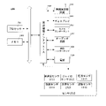
説明すべきものとして、端末は、現在表示画面に仮想シーンを全画面表示し、該現在表示画面の所定領域にグローバルマップを独立して表示してもよい。ここで、該グローバルマップは、該仮想シーンのサムネイルを表示するために用いられる。該サムネイルは、該仮想シーンに対応する地形、地貌、地理位置などの地理的な特徴を描くために用いられる。該所定領域は、ユーザの操作習慣に応じて設定されてもよい。例えば、図1に示すように、該所定領域は、該現在表示画面の右上隅又は左下隅の矩形領域などであってもよい。 As a matter of explanation, the terminal may display the virtual scene in full screen on the current display screen and independently display the global map in a predetermined area of the current display screen. Here, the global map is used to display thumbnails of the virtual scene. The thumbnail is used to depict geographical features such as terrain, geography, and geographic location corresponding to the virtual scene. The predetermined area may be set according to the operation habit of the user. For example, as shown in FIG. 1, the predetermined area may be a rectangular area in the upper right corner or the lower left corner of the current display screen.
なお、該端末は、該アプリケーションプログラムをインストールした任意の端末であってもよいが、本願発明の実施例はこれを具体的に限定しない。例えば、端末は、携帯電話端末、タブレットコンピュータ(PAD:Portable Android Device)端末、又はコンピュータ端末など、該アプリケーションプログラムをインストールした任意の機器であってもよい。 The terminal may be any terminal on which the application program is installed, but the embodiment of the present invention does not specifically limit this. For example, the terminal may be any device on which the application program is installed, such as a mobile phone terminal, a tablet computer (PAD) terminal, or a computer terminal.
図2は、本願発明の実施例で提供されたマークポイント位置表示方法のフローチャートである。該方法は、電子機器に適用される。本願発明の実施例では、該電子機器を端末として説明するが、該方法の実行主体は、端末であってもよい。図2に示すように、該方法は、以下のステップを含む。 FIG. 2 is a flowchart of the mark point position display method provided in the embodiment of the present invention. The method applies to electronic devices. In the embodiment of the present invention, the electronic device will be described as a terminal, but the execution subject of the method may be a terminal. As shown in FIG. 2, the method comprises the following steps.
201で、該グローバルマップ上の選定操作を検出すると、端末は、該選定操作により選定された位置座標を取得し、グローバルマップ上の該位置座標に対応する位置を該マークポイント位置として決定する。 When the selection operation on the global map is detected in 201, the terminal acquires the position coordinates selected by the selection operation and determines the position corresponding to the position coordinates on the global map as the mark point position.
本願発明の実施例で、該マークポイント位置は、該グローバルマップ上の選定された位置である。ゲームをプレーする際に、ユーザは、ある目的地に到達したい場合、グローバルマップ上で該目的地を選定し、該目的地をマークポイントとしてマーク付けしてもよい。該マークポイント位置が、該目的地の該グローバルマップ上の位置である。ここで、該マークポイント位置は、該グローバルマップ上の位置座標で表すことができる。端末は、該マークポイントのグローバルマップ上の位置座標を取得し、グローバルマップ上の該位置座標に対応する位置を該マークポイント位置として決定してもよい。 In the embodiment of the present invention, the mark point position is a selected position on the global map. When playing a game, the user may select the destination on the global map and mark the destination as a mark point if he / she wants to reach a certain destination. The mark point position is the position of the destination on the global map. Here, the mark point position can be represented by the position coordinates on the global map. The terminal may acquire the position coordinates of the mark point on the global map and determine the position corresponding to the position coordinates on the global map as the mark point position.
ここで、該マークポイント位置は、現在ユーザによる選定操作に基づいて選定されてもよい。該選定操作は、ユーザの指のタッチイベントでトリガされる操作であってもよいし、マウス又はその他の入力デバイスのクリックイベントでトリガされる操作であってもよい。したがって、本ステップは、端末が、該グローバルマップ上でタッチイベント又はクリックイベントが発生したことを検出すると、該グローバルマップ上に選定操作が存在すると決定し、該タッチイベント又はクリックイベントの該グローバルマップ上の位置座標を取得し、該位置座標を該選定操作により選定された位置座標として決定するステップであってもよい。 Here, the mark point position may be selected based on a selection operation currently performed by the user. The selection operation may be an operation triggered by a touch event of the user's finger, or an operation triggered by a click event of a mouse or other input device. Therefore, this step determines that a selection operation exists on the global map when the terminal detects that a touch event or click event has occurred on the global map, and the global map of the touch event or click event. It may be a step of acquiring the above position coordinates and determining the position coordinates as the position coordinates selected by the selection operation.
ここで、端末は、所定アイコンを追加することにより、該マークポイント位置をマーク付けしてもよい。端末は、該マークポイント位置に所定アイコンを追加してもよいし、現在表示画面におけるいずれかの位置に所定アイコンを追加し、該所定アイコンの指示情報を表示してもよい。該指示情報は、該所定アイコンがマークポイント位置の周囲の領域を遮蔽しないように、該マークポイント位置の所定アイコンを指示するためのものである。該所定アイコンは、水滴アイコン、矢印などであってもよい。図3に示すように、端末は、該グローバルマップを該現在表示画面の右上隅に表示してもよい。ユーザがグローバルマップ上のマークポイント位置を指で選定すると、端末は、該位置に水滴アイコンを付けてもよい。図4は、実際の端末画面表示の模式図を提供している。図4に示す効果比較の模式図を参照すると、その具体的な表示効果がより明らかになる。 Here, the terminal may mark the mark point position by adding a predetermined icon. The terminal may add a predetermined icon to the mark point position, or may add a predetermined icon to any position on the current display screen and display instruction information of the predetermined icon. The instruction information is for instructing the predetermined icon at the mark point position so that the predetermined icon does not block the area around the mark point position. The predetermined icon may be a water drop icon, an arrow, or the like. As shown in FIG. 3, the terminal may display the global map in the upper right corner of the current display screen. When the user selects a mark point position on the global map with a finger, the terminal may attach a water drop icon to the position. FIG. 4 provides a schematic diagram of an actual terminal screen display. The specific display effect becomes clearer by referring to the schematic diagram of the effect comparison shown in FIG.
1つの可能な実施形態では、ユーザは、他のユーザとチームを組んでゲームをプレーしてもよい。したがって、複数のユーザがゲームをプレーするとき、該複数のユーザがそれぞれ制御する制御オブジェクトの間は関連付けられる。該マークポイント位置が該複数の制御オブジェクトのうちいずれかのオブジェクトにより選定され、かつマークポイント位置を選定した制御オブジェクトが、関連付けられた制御オブジェクトに該マークポイント位置を共有するようにしてもよい。該マークポイント位置が該現在制御オブジェクトの関連オブジェクトにより選定される場合、ステップ201は、端末が、該現在制御オブジェクトの関連オブジェクトにより選定された該マークポイント位置を受信するステップに置き換えられてもよい。ここで、該関連オブジェクトは、該マークポイント位置の位置座標をそのまま送信してもよい。端末は、該関連オブジェクトの端末から送信された位置座標を受信し、該グローバルマップ上の該位置座標に対応する位置を該マークポイント位置として決定する。 In one possible embodiment, the user may team up with another user to play the game. Therefore, when a plurality of users play a game, control objects controlled by the plurality of users are associated with each other. The mark point position may be selected by any one of the plurality of control objects, and the control object for which the mark point position has been selected may share the mark point position with the associated control object. If the markpoint position is selected by a related object of the current control object, step 201 may be replaced by a step in which the terminal receives the markpoint position selected by the related object of the current control object. .. Here, the related object may transmit the position coordinates of the mark point position as it is. The terminal receives the position coordinates transmitted from the terminal of the related object, and determines the position corresponding to the position coordinates on the global map as the mark point position.
ここで、該関連オブジェクトの選定は、即ち、該ユーザに関連付けられる関連ユーザの選定である。当然のことながら、該関連オブジェクトの選定過程は、上記現在ユーザによる選定操作に基づいて選定する過程と同様の過程であり、ここでは説明を省略する。 Here, the selection of the related object is, that is, the selection of the related user associated with the user. As a matter of course, the process of selecting the related object is the same as the process of selecting based on the selection operation by the current user, and the description thereof is omitted here.
1つの可能な実施形態では、該端末は、ユーザによりトリガされた表示指示を受信した場合にのみ、該グローバルマップを表示してもよい。該グローバルマップ上の選定操作を検出すると、端末が、該選定操作により選定された位置座標を取得するステップは、端末が、該グローバルマップの表示を指示する表示指示を検出すると、該グローバルマップを現在表示画面の所定領域に表示し、該グローバルマップ上の選定操作を検出すると、該グローバルマップ上の選定操作により選定された位置座標を取得するステップであってもよい。 In one possible embodiment, the terminal may display the global map only when it receives a user-triggered display instruction. When the terminal detects the selection operation on the global map, the step of acquiring the position coordinates selected by the selection operation is that when the terminal detects the display instruction instructing the display of the global map, the global map is displayed. When the display is displayed in a predetermined area of the current display screen and the selection operation on the global map is detected, the step may be a step of acquiring the position coordinates selected by the selection operation on the global map.
ここで、該表示指示は、端末の現在表示画面の表示ボタン、指定の音声、又はユーザが該端末に対して実行したシェイク、回転などの指定の動作によってトリガされてもよい。 Here, the display instruction may be triggered by a display button on the current display screen of the terminal, a designated voice, or a designated action such as a shake or rotation performed by the user on the terminal.
さらに、端末は、所定領域内に該グローバルマップを表示した後、ユーザが該グローバルマップ上で選定操作を実行する必要があるか否かをさらに検出してもよい。ユーザが該グローバルマップ上で選定操作を実行する必要がある場合、該端末は、ユーザが拡大表示されたグローバルマップ上で選定を行えるように、該グローバルマップをさらに拡大表示してもよい。これに対応して、該グローバルマップ上の選定操作を検出すると、端末が、該選定操作により選定された位置座標を取得するステップは、端末の所定領域のトリガ操作を検出すると、端末が、該グローバルマップを第1ウィンドウから第2ウィンドウに切り替えて表示し、該第2ウィンドウのグローバルマップ上の選定操作を検出すると、端末が、該選定操作により選択された位置座標を取得するステップであってもよい。 Further, the terminal may further detect whether or not the user needs to perform a selection operation on the global map after displaying the global map in a predetermined area. If the user needs to perform a selection operation on the global map, the terminal may further magnify the global map so that the user can make a selection on the magnified global map. Correspondingly, when the selection operation on the global map is detected, the terminal acquires the position coordinates selected by the selection operation. When the terminal detects the trigger operation in the predetermined area of the terminal, the terminal causes the selection operation. This is a step in which the terminal acquires the position coordinates selected by the selection operation when the global map is displayed by switching from the first window to the second window and the selection operation on the global map of the second window is detected. May be good.
ここで、該第2ウィンドウの表示領域は、該第1ウィンドウよりも大きく、該トリガ操作は、該所定領域での指のタッチイベント、又は該所定領域でのマウスのクリックイベントである。該所定領域は、必要に応じて設定されてもよい。例えば、該所定領域は、該第1ウィンドウが占める全領域、又は、該第1ウィンドウが占める領域の中央領域、エッジ領域などであってもよい。該第1ウィンドウは、現在表示画面の右上隅領域、左下隅領域などであってもよい。該第2ウィンドウは、該現在表示画面の左半分の領域又は右半分の領域などであってもよい。 Here, the display area of the second window is larger than that of the first window, and the trigger operation is a finger touch event in the predetermined area or a mouse click event in the predetermined area. The predetermined area may be set as needed. For example, the predetermined area may be the entire area occupied by the first window, or the central area, edge area, or the like of the area occupied by the first window. The first window may be an upper right corner area, a lower left corner area, or the like of the current display screen. The second window may be an area on the left half or an area on the right half of the current display screen.
説明すべきものとして、該グローバルマップは、該端末のスクリーンの右上隅、右下隅などの一部のスクリーン領域に位置してもよい。端末が、該グローバルマップを、表示面積がより大きい領域に切り替えて表示することにより、端末のスクリーンサイズの制限が解除され、マークポイント位置の選定の正確性が向上し、ユーザ体験が向上する。 As a matter of explanation, the global map may be located in a part of the screen area such as the upper right corner, the lower right corner, etc. of the screen of the terminal. By switching the global map to an area having a larger display area and displaying the global map, the limitation on the screen size of the terminal is lifted, the accuracy of selecting the mark point position is improved, and the user experience is improved.
図5に示すように、端末は、まず、左図に示すように、端末のスクリーンの右上隅に該グローバルマップを表示し、ユーザの指が該右上隅の領域にタッチすると、右図に示すように、該グローバルマップを右半分の領域に切り替えて表示してもよい。図5に示すように、端末は、ユーザが図中から該現在制御オブジェクトの現在位置と該マークポイント位置との位置関係を直接観測できるように、該現在制御オブジェクトの位置を該グローバルマップに表示してもよい。さらに、図5に示すように、端末は、該現在制御オブジェクトの現在移動方向を該グローバルマップに表示してもよい。これにより、ユーザは、該マークポイント位置に基づいて該現在移動方向を適時に調整し、迂回などの事態の発生を回避し、該マークポイント位置になるべく早く到達することができる。図6は、実際の端末画面表示の模式図を提供している。図6に示す効果比較の模式図を参照すると、その具体的な表示効果がより明らかになる。 As shown in FIG. 5, the terminal first displays the global map in the upper right corner of the screen of the terminal as shown in the left figure, and when the user's finger touches the area in the upper right corner, it is shown in the right figure. As such, the global map may be switched to the right half area and displayed. As shown in FIG. 5, the terminal displays the position of the current control object on the global map so that the user can directly observe the positional relationship between the current position of the current control object and the mark point position in the figure. You may. Further, as shown in FIG. 5, the terminal may display the current moving direction of the current control object on the global map. As a result, the user can adjust the current moving direction in a timely manner based on the mark point position, avoid the occurrence of detours, and reach the mark point position as soon as possible. FIG. 6 provides a schematic diagram of an actual terminal screen display. The specific display effect becomes clearer by referring to the schematic diagram of the effect comparison shown in FIG.
図7に示すように、端末は、該グローバルマップに現在制御オブジェクトと関連オブジェクトとの位置をマーク付けしてもよい。また、端末は、該マークポイント位置の現在の色を、該マークポイントを選定した関連オブジェクトの位置がマーク付けされた色に設定してもよい。これにより、ユーザは、視覚の角度から、該マークポイント位置を選定したオブジェクトを直感的に知ることができる。図8は、実際の端末画面表示の模式図を提供している。図8に示す効果比較の模式図を参照すると、その具体的な表示効果がより明らかになる。 As shown in FIG. 7, the terminal may mark the position of the current control object and the related object on the global map. Further, the terminal may set the current color of the mark point position to the color marked with the position of the related object for which the mark point is selected. As a result, the user can intuitively know the object for which the mark point position is selected from the visual angle. FIG. 8 provides a schematic diagram of an actual terminal screen display. The specific display effect becomes clearer by referring to the schematic diagram of the effect comparison shown in FIG.
説明すべきものとして、該現在制御オブジェクトがマークポイント位置を選定する際に、該現在制御オブジェクトが他のオブジェクトと関連付けられた場合、該現在制御オブジェクトは、該マークポイント位置を該関連オブジェクトと共有する必要もある。該過程は、端末が、該関連オブジェクトのオブジェクト識別子を取得し、該オブジェクト識別子に基づいて、該マークポイント位置を該関連オブジェクトに送信することであってもよい。ここで、該オブジェクト識別子は、該関連オブジェクトのゲーム身分識別番号(ID:Identity)、ニックネームなどであってもよい。ここで、該端末は、サーバと通信接続を確立し、該マークポイント位置をサーバに送信し、該サーバによって、該マークポイント位置を、関連オブジェクトが存在する端末に転送してもよい。又は、該端末は、該関連オブジェクトが存在する端末と、例えば、ブルートゥース(登録商標)接続、近距離無線通信(NFC:Near Field Communication)接続などのような通信接続を直接確立し、該通信接続に基づいて、該マークポイント位置を、該関連オブジェクトが存在する端末に直接送信してもよい。 As a matter of explanation, when the current control object selects a mark point position, if the current control object is associated with another object, the current control object shares the mark point position with the related object. There is also a need. The process may be that the terminal obtains the object identifier of the related object and sends the markpoint position to the related object based on the object identifier. Here, the object identifier may be a game identification number (ID: Identity), a nickname, or the like of the related object. Here, the terminal may establish a communication connection with the server, transmit the markpoint position to the server, and transfer the markpoint position to the terminal in which the related object exists by the server. Alternatively, the terminal directly establishes a communication connection with the terminal in which the related object exists, such as a Bluetooth® connection, a Near Field Communication (NFC) connection, and the like. The mark point position may be transmitted directly to the terminal in which the related object exists based on the above.
当然のことながら、端末は、該マークポイント位置を取得すると、まず、グローバルマップ上に該マークポイント位置をマーク付けしてから、該マークポイント位置を関連オブジェクトに送信してもよいし、まず、該マークポイント位置を関連オブジェクトに送信してから、マーク付けを行ってもよいし、同時に送信及びマーク付けを行ってもよい。本願発明の実施例は、これを具体的に限定しない。 As a matter of course, when the terminal acquires the mark point position, the terminal may first mark the mark point position on the global map and then send the mark point position to the related object. The mark point position may be transmitted to the related object and then marked, or simultaneously transmitted and marked. The embodiments of the present invention do not specifically limit this.
本願発明の実施例では、端末は、該マークポイント位置を取得した後に、該マークポイント位置のグローバルマップ上の位置に基づいて、以下のステップ202により、該マークポイント位置で示されるターゲットシーン領域を決定し、仮想シーンにおいて該ターゲットシーン領域をマーク付けしてもよい。これにより、現在制御オブジェクトは、該マークポイント位置を明確に知ることができる。
In the embodiment of the present invention, after acquiring the mark point position, the terminal obtains the target scene area indicated by the mark point position by the following
202で、端末は、該仮想シーンにおいて該マークポイント位置で示されるターゲットシーン領域を決定する。 At 202, the terminal determines the target scene area indicated by the mark point position in the virtual scene.
ここで、該ターゲットシーン領域は、該マークポイント位置でマーク付けされる領域であり、該グローバルマップに表示されるのは、該仮想シーンのサムネイルである。該グローバルマップと該仮想シーンとの間にマッピング関係があり、端末は、該マッピング関係を予め記憶してもよい。端末は、該マッピング関係に基づいて、該仮想シーンにおいて該マークポイント位置で示されるターゲットシーン領域を決定する。 Here, the target scene area is an area marked at the mark point position, and what is displayed on the global map is a thumbnail of the virtual scene. There is a mapping relationship between the global map and the virtual scene, and the terminal may store the mapping relationship in advance. The terminal determines the target scene area indicated by the mark point position in the virtual scene based on the mapping relationship.
ここで、該マッピング関係は、グローバルマップ上の位置ポイントと、仮想シーンにおける位置ポイントとのマッピング関係であってもよいし、グローバルマップ上の位置ポイントと、仮想シーンにおけるシーン領域とのマッピング関係であってもよい。該マッピング関係のいくつかの可能性に応じて、本ステップは、以下の3つの形態で実現することができる。 Here, the mapping relationship may be a mapping relationship between a position point on the global map and a position point in the virtual scene, or a mapping relationship between the position point on the global map and the scene area in the virtual scene. There may be. Depending on some possibilities of the mapping relationship, this step can be realized in the following three forms.
1つ目の形態として、端末は、該マークポイント位置の該グローバルマップ上の位置座標に基づいて、該仮想シーンにおける、該マークポイント位置に対応するシーン位置座標を決定し、該シーン位置座標の第1所定範囲内の領域を該ターゲットシーン領域として決定する。 As the first form, the terminal determines the scene position coordinates corresponding to the mark point position in the virtual scene based on the position coordinates of the mark point position on the global map, and determines the scene position coordinates of the scene position coordinates. A region within the first predetermined range is determined as the target scene region.
本ステップで、端末は、該グローバルマップ上の位置座標と、該仮想シーンにおけるシーン位置座標とのマッピング関係を予め記憶してもよい。端末は、該マークポイント位置の該グローバルマップ上の位置座標に基づいて、該マッピング関係から、該仮想シーンにおける、該マークポイント位置に対応するシーン位置座標を取得する。そして、端末は、該シーン位置座標に基づいて、所定の生成原則に従って、該シーン位置座標に対応する第1所定範囲内の領域を該ターゲットシーン領域とする。 In this step, the terminal may store in advance the mapping relationship between the position coordinates on the global map and the scene position coordinates in the virtual scene. The terminal acquires the scene position coordinates corresponding to the mark point position in the virtual scene from the mapping relationship based on the position coordinates of the mark point position on the global map. Then, the terminal sets the area within the first predetermined range corresponding to the scene position coordinates as the target scene area according to the predetermined generation principle based on the scene position coordinates.
ここで、該所定の生成原則は、必要に応じて設定されてもよいが、本願発明の実施例は、これを具体的に限定しない。例えば、該所定の生成原則は、図9に示すように、該シーン位置座標を円心として、所定距離を半径とする領域を生成することであってもよい。この場合、該第1所定範囲内の領域は、即ち、円心がポイントOであり、半径がRである円形領域である。又は、該所定の生成原則は、該シーン位置座標を中心として、所定距離を辺長とする正方形領域を生成することであってもよい。この場合、該第1所定範囲内の領域は、即ち、中心がポイントOであり、辺長がaである正方形領域である。 Here, the predetermined generation principle may be set as needed, but the embodiments of the present invention do not specifically limit this. For example, as shown in FIG. 9, the predetermined generation principle may be to generate a region having the scene position coordinates as the center of the circle and a predetermined distance as the radius. In this case, the region within the first predetermined range is a circular region where the center of the circle is the point O and the radius is R. Alternatively, the predetermined generation principle may be to generate a square region having a predetermined distance as a side length with the scene position coordinates as the center. In this case, the region within the first predetermined range is a square region where the center is the point O and the side length is a.
説明すべきものとして、端末が、該マークポイント位置を仮想シーンにおける1つの位置ポイントに精確に対応付け、該位置ポイントに基づいて、該位置ポイントを一定の領域範囲内の領域に拡大することにより、仮想シーンにおけるターゲットシーン領域が正確に決定され、現在ユーザによる該ターゲットシーン領域の識別度が高まり、ユーザ体験が向上する。 As an explanation, the terminal accurately maps the mark point position to one position point in the virtual scene, and expands the position point to an area within a certain area range based on the position point. The target scene area in the virtual scene is accurately determined, the degree of identification of the target scene area by the current user is increased, and the user experience is improved.
2つ目の形態として、端末は、該マークポイント位置の該グローバルマップ上の位置座標に基づいて、該マークポイント位置の該仮想シーンにおけるシーン位置座標を決定し、該シーン位置座標上の地物要素に対応する領域を該ターゲットシーン領域として決定する。 As a second form, the terminal determines the scene position coordinates of the mark point position in the virtual scene based on the position coordinates of the mark point position on the global map, and the feature on the scene position coordinates. The area corresponding to the element is determined as the target scene area.
本ステップで、端末は、シーン位置座標と地物要素とのマッピング関係を記憶してもよい。端末は、マークポイント位置の該仮想シーンにおけるシーン位置座標を決定し、該シーン位置座標に基づいて、シーン位置座標と地物要素とのマッピング関係から、該シーン位置座標に対応する地物要素を決定し、該地物要素が存在する領域を該ターゲットシーン領域とする。 In this step, the terminal may store the mapping relationship between the scene position coordinates and the feature element. The terminal determines the scene position coordinates of the mark point position in the virtual scene, and based on the scene position coordinates, the feature element corresponding to the scene position coordinates is obtained from the mapping relationship between the scene position coordinates and the feature element. The area where the feature element is present is defined as the target scene area.
該地物要素は、仮想シーンにおいて一定の外形輪郭又は建築構造を有する要素であってもよく、例えば、該地物要素は、湖沼、公園、別荘、病院などであってもよい。端末がマークポイント位置の該仮想シーンにおけるシーン位置座標を決定する形態は、上記1つ目の形態と同様であり、ここでは説明を省略する。 The feature element may be an element having a certain outline or building structure in a virtual scene, and for example, the feature element may be a lake, a park, a villa, a hospital, or the like. The form in which the terminal determines the scene position coordinates in the virtual scene of the mark point position is the same as the first form described above, and the description thereof will be omitted here.
説明すべきものとして、端末は、該マークポイント位置を、該仮想シーンにおけるある地物要素、例えば、病院や公園などに対応付けてもよい。これにより、該ターゲットシーン領域をより明確にし、該仮想シーンにおける該ターゲットシーン領域の識別度を向上させる。そして、該マークポイント位置をある建物又は地理的要素にマッピングすることにより、視覚的に、該ターゲットシーン領域の地理的な範囲の画定がより明確になり、該ターゲットシーン領域の決定の正確性が向上し、ユーザの視覚的な体験が向上する。 As a matter of explanation, the terminal may associate the mark point position with a certain feature element in the virtual scene, such as a hospital or a park. This makes the target scene area clearer and improves the degree of discrimination of the target scene area in the virtual scene. Then, by mapping the mark point position to a building or a geographical element, the delimitation of the geographical range of the target scene area becomes clearer visually, and the accuracy of the determination of the target scene area becomes clearer. Improves and enhances the user's visual experience.
さらに、該ターゲットシーン領域をある地物要素に具現化することにより、現在制御オブジェクトが、該地物要素の識別子や外形輪郭などの特徴に基づいて、該ターゲットシーン領域を予め把握しておくことができ、該ターゲットシーン領域に到達する前に、ゲーム経験に基づいて準備作業を整えることができ、さらに、ユーザのゲーム体験が大幅に向上する。 Further, by embodying the target scene area into a certain feature element, the control object currently grasps the target scene area in advance based on features such as an identifier of the feature element and an outline contour. It is possible to prepare the preparatory work based on the game experience before reaching the target scene area, and further, the game experience of the user is greatly improved.
3つ目の形態として、端末は、該マークポイント位置の該グローバルマップ上の位置座標に基づいて、位置座標とシーン領域とのマッピング関係から、仮想シーンにおける、該位置座標に対応するターゲットシーン領域を検索する。 As a third form, the terminal has a target scene area corresponding to the position coordinates in the virtual scene based on the mapping relationship between the position coordinates and the scene area based on the position coordinates of the mark point position on the global map. To search for.
本願発明の実施例では、該グローバルマップは、実際に、該仮想シーンが所定の割合で縮小されたサムネイルである。該グローバルマップ上の位置ポイントは、該仮想シーンにおける仮想領域を表すために用いられてもよい。端末は、グローバルマップ上の位置座標と該仮想シーンにおけるシーン領域との対応関係を予め関連付けて記憶してもよい。端末は、該マークポイント位置の該グローバルマップ上の位置座標に基づいて、位置座標とシーン領域とのマッピング関係から、該位置座標に対応するシーン領域を決定し、該シーン領域を、該マークポイント位置に対応するターゲットシーン領域とする。 In the embodiment of the present invention, the global map is actually a thumbnail in which the virtual scene is reduced by a predetermined ratio. Position points on the global map may be used to represent a virtual area in the virtual scene. The terminal may store the correspondence between the position coordinates on the global map and the scene area in the virtual scene in advance in association with each other. The terminal determines the scene area corresponding to the position coordinates from the mapping relationship between the position coordinates and the scene area based on the position coordinates of the mark point position on the global map, and sets the scene area as the mark point. The target scene area corresponding to the position.
1つの可能な実施形態では、該端末は、関連オブジェクトが該ターゲットシーン領域を知るように、該関連オブジェクトに該ターゲットシーン領域を送信してもよい。該端末が該関連オブジェクトにマークポイント位置を送信し、該関連オブジェクトが該マークポイント位置に基づいてターゲットシーン領域を決定してもよい。当然のことながら、該端末は、関連オブジェクトに該マークポイント位置とターゲットシーン領域とを送信してもよい。本願発明の実施例は、これを具体的に限定しない。 In one possible embodiment, the terminal may transmit the target scene area to the related object so that the related object knows the target scene area. The terminal may transmit a markpoint position to the related object, and the related object may determine a target scene area based on the markpoint position. As a matter of course, the terminal may transmit the mark point position and the target scene area to the related object. The embodiments of the present invention do not specifically limit this.
説明すべきものとして、端末は、位置座標とシーン領域とのマッピング関係を記憶することにより、直接的に、該マッピング関係に基づいて、該ターゲットシーン領域を迅速に決定することができる。これにより、端末の処理効率が大幅に向上する。 As a matter of explanation, the terminal can quickly determine the target scene area directly based on the mapping relationship by storing the mapping relationship between the position coordinates and the scene area. This greatly improves the processing efficiency of the terminal.
現在制御オブジェクトが該ターゲットシーン領域に徐々に移動する過程では、該現在制御オブジェクトの画角画像の範囲が限られているため、該ターゲットシーン領域が該現在制御オブジェクトの位置から遠い場合、該ターゲットシーン領域が該画角画像に入らない可能性がある。したがって、端末は、該現在制御オブジェクトの画角画像と該ターゲットシーン領域の位置とに基づいて、該画角画像に該ターゲットシーン領域が含まれるか否かを判断し、判断結果に基づいて該ターゲットシーン領域をマーク付けしてもよい。 In the process of gradually moving the current control object to the target scene area, the range of the angle of view image of the current control object is limited. Therefore, if the target scene area is far from the position of the current control object, the target The scene area may not fit in the angle of view image. Therefore, the terminal determines whether or not the angle of view image includes the target scene area based on the angle of view image of the current control object and the position of the target scene area, and based on the determination result, the terminal determines whether or not the target scene area is included. You may mark the target scene area.
203で、画角画像に該ターゲットシーン領域が含まれない場合、端末は、該画角画像において該ターゲットシーン領域の方向に該提示信号を表示する。 At 203, if the angle of view image does not include the target scene area, the terminal displays the presentation signal in the direction of the target scene area in the angle of view image.
ここで、該画角画像は、該仮想シーンにおいて該現在制御オブジェクトの画角範囲内で観測可能な仮想シーンであり、該提示信号は、該ターゲットシーン領域の該画角画像における位置を提示するために用いられる。該制御オブジェクトが該ターゲットシーン領域から遠い場合、端末は、該画角画像において該ターゲットシーン領域の方向に沿った地平線位置に該提示信号を表示してもよい。該提示信号は、ターゲットシーン領域の位置する方向に沿った遠方の地平線位置にあるひと筋の狼煙、点滅している1つの信号灯などであってもよい。 Here, the angle of view image is a virtual scene that can be observed within the angle of view range of the current control object in the virtual scene, and the presented signal presents the position of the target scene region in the angle of view image. Used for. If the control object is far from the target scene area, the terminal may display the presentation signal at a horizon position along the direction of the target scene area in the angle of view image. The presented signal may be a line of signal smoke at a distant horizon position along the direction in which the target scene region is located, a single blinking signal light, or the like.
説明すべきものとして、端末は、提示信号を表示することにより、現在制御オブジェクトの画角画像の範囲が限られていても、該仮想シーンにおいて該ターゲットシーン領域のおおよその方向を生き生きと描画して、該現在制御オブジェクトが該ターゲットシーン領域の位置する方向に移動するようにガイドしてもよい。これにより、該現在制御オブジェクトは、該ターゲットシーン領域を迅速に探し出すことができる。 It should be explained that by displaying the presentation signal, the terminal vividly draws the approximate direction of the target scene area in the virtual scene even if the range of the angle of view image of the control object is currently limited. , The current control object may be guided to move in the direction in which the target scene area is located. This allows the current control object to quickly find the target scene area.
204で、該画角画像に該ターゲットシーン領域が含まれる場合、端末は、該画角画像における該ターゲットシーン領域の第2所定範囲内に該提示信号を表示する。 At 204, when the angle of view image includes the target scene area, the terminal displays the presentation signal within the second predetermined range of the target scene area in the angle of view image.
ここで、該提示信号は、文字提示、アイコン提示、及び/又は表示特殊効果であってもよい。端末は、該現在制御オブジェクトが該ターゲットシーン領域を正確に探し出すことができるように、該画角画像における該ターゲットシーン領域の第2所定範囲内に該提示信号を表示してもよい。該第2所定範囲は、該ターゲットシーン領域が位置する領域、該ターゲットシーン領域の右上隅の領域などであってもよく、本願発明の実施例は、これを具体的に限定しない。 Here, the presentation signal may be character presentation, icon presentation, and / or display special effects. The terminal may display the presentation signal within a second predetermined range of the target scene area in the angle of view image so that the current control object can accurately find the target scene area. The second predetermined range may be a region where the target scene region is located, a region in the upper right corner of the target scene region, or the like, and the embodiments of the present invention do not specifically limit this.
該提示信号のいくつかの可能性に基づいて、本ステップは、以下の3つの形態で実現することができる。 Based on some possibilities of the presented signal, this step can be realized in the following three forms.
1つ目の形態として、該提示信号が文字提示である場合、本ステップは、端末が、該画角画像において、該ターゲットシーン領域に対応する第3所定範囲内に、該文字提示を表示するステップであってもよい。 As the first form, when the presentation signal is a character presentation, in this step, the terminal displays the character presentation within a third predetermined range corresponding to the target scene area in the angle of view image. It may be a step.
本ステップで、端末は、該ターゲットシーン領域に対応する文字提示を予め記憶しておき、端末がターゲットシーン領域を決定した後に、該ターゲットシーン領域に対応する文字提示を指定の記憶領域から取得し、該文字提示を該ターゲットシーン領域の第3所定範囲内に挿入してもよい。 In this step, the terminal stores the character presentation corresponding to the target scene area in advance, and after the terminal determines the target scene area, acquires the character presentation corresponding to the target scene area from the designated storage area. , The character presentation may be inserted within a third predetermined range of the target scene area.
説明すべきものとして、該第3所定範囲は、上記第2所定範囲と同じであってもよいし、異なっていてもよい。該第3所定範囲は、該ターゲットシーン領域の右上隅の領域であってもよいし、該ターゲットシーン領域の中央領域などであってもよい。該文字提示は、ユーザのニーズに応じて設定されてもよく、本願発明の実施例は、これを具体的に限定しない。例えば、該文字提示は、「ここは目的地である!」、「目的地はここにある!」などであってもよい。 As a matter of explanation, the third predetermined range may be the same as or different from the second predetermined range. The third predetermined range may be a region in the upper right corner of the target scene region, a central region of the target scene region, or the like. The character presentation may be set according to the needs of the user, and the embodiments of the present invention do not specifically limit this. For example, the character presentation may be "this is the destination!", "The destination is here!", And the like.
2つ目の形態として、該提示信号がアイコン提示である場合、本ステップは、端末が、該画角画像において、該ターゲットシーン領域に対応する第4所定範囲内に、該アイコン提示を追加するステップであってもよい。 As a second form, when the presentation signal is an icon presentation, in this step, the terminal adds the icon presentation within the fourth predetermined range corresponding to the target scene area in the angle of view image. It may be a step.
ここで、該アイコン提示は、ユーザのニーズに応じて設定されてもよく、本願発明の実施例は、これを具体的に限定しない。例えば、該アイコン提示は、該ターゲットシーン領域を指し示す指アイコン、旗アイコンなどであってもよい。本ステップの具体的な実現形態は、1つ目の形態と同様であり、ここでは説明を省略する。 Here, the icon presentation may be set according to the needs of the user, and the embodiments of the present invention do not specifically limit this. For example, the icon presentation may be a finger icon, a flag icon, or the like pointing to the target scene area. The specific embodiment of this step is the same as that of the first embodiment, and the description thereof will be omitted here.
3つ目の形態として、該提示信号が表示特殊効果である場合、本ステップは、端末が、該画角画像において、該ターゲットシーン領域に対応する第5所定範囲内に、該表示特殊効果を追加するステップであってもよい。 As a third form, when the presented signal is a display special effect, in this step, the terminal displays the display special effect within the fifth predetermined range corresponding to the target scene area in the angle of view image. It may be an additional step.
本ステップで、該表示特殊効果は、該ターゲットシーン領域に対して色替え表示を行ったり、該ターゲットシーン領域にいくつかの動的な画像を追加したり、該ターゲットシーン領域を点滅表示したりするなどであってもよい。具体的には、本ステップは、端末が、該ターゲットシーン領域の元の表示色をターゲット色に変え、又は、該ターゲットシーン領域のレイヤーの上のレイヤーに動的な画像を表示し、又は、該第5所定範囲内で点滅特殊効果を再生するステップであってもよい。 In this step, the display special effects display the target scene area in different colors, add some dynamic images to the target scene area, and blink the target scene area. It may be done. Specifically, in this step, the terminal changes the original display color of the target scene area to the target color, or displays a dynamic image on a layer above the layer of the target scene area, or. It may be a step of reproducing the blinking special effect within the fifth predetermined range.
ここで、端末は、レイヤーを追加することで、該表示特殊効果の追加過程を実現してもよい。具体的には、端末は、該ターゲットシーン領域のレイヤーの上にレイヤーを追加してもよい。端末が該ターゲットシーン領域の元の表示色をターゲット色に変える場合、該追加されたレイヤーにおいて、端末は、該追加されたレイヤーにおける、該ターゲットシーン領域に対応する領域に該ターゲット色を描画する。端末が該ターゲットシーン領域のレイヤーの上のレイヤーに動的な画像を表示する場合、該追加されたレイヤーにおいて、端末は、該ターゲットシーン領域に対応する周辺領域に該動的な画像を描画する。該動的な画像は、該ターゲットシーン領域の周りに移動する煙の画像や、該ターゲットシーン領域に到達した関連チームメイトのジャンプの画像などであってもよい。 Here, the terminal may realize the process of adding the display special effect by adding a layer. Specifically, the terminal may add a layer on the layer of the target scene area. When the terminal changes the original display color of the target scene area to the target color, in the added layer, the terminal draws the target color in the area corresponding to the target scene area in the added layer. .. When the terminal displays a dynamic image in a layer above the layer of the target scene area, in the added layer, the terminal draws the dynamic image in the peripheral area corresponding to the target scene area. .. The dynamic image may be an image of smoke moving around the target scene area, an image of a related teammate jumping to reach the target scene area, and the like.
また、端末がターゲットシーン領域に対応する第5所定範囲内で点滅特殊効果を再生する場合、端末は、所定周期毎に該ターゲットシーン領域に対して1回のハイライト表示を行ってもよい。これにより、該ターゲットシーン領域を点滅表示するような効果を奏する。 Further, when the terminal reproduces the blinking special effect within the fifth predetermined range corresponding to the target scene area, the terminal may perform one highlight display on the target scene area at predetermined intervals. This has the effect of blinking the target scene area.
ここで、該ターゲット色が該ターゲットシーン領域の元の表示色と異なってもよいし、該ターゲット色が該ターゲット表示シーン領域の周辺シーン領域の表示色と異なっていてもよい。該端末は、該ターゲットシーン領域の元の表示色に基づいて、元の表示色と異なる色をターゲット色としてもよい。又は、該端末は、該ターゲットシーン領域を周辺シーン領域と明確に区別できるように、周辺シーン領域の表示色と異なる色をターゲット色としてもよい。 Here, the target color may be different from the original display color of the target scene area, or the target color may be different from the display color of the peripheral scene area of the target display scene area. The terminal may use a color different from the original display color as the target color based on the original display color of the target scene area. Alternatively, the terminal may use a color different from the display color of the peripheral scene area as the target color so that the target scene area can be clearly distinguished from the peripheral scene area.
図10に示すように、端末は、該ターゲットシーン領域をターゲット色に変更して、該画角画像における他の領域と区別してもよい。図11は、実際の端末画面表示の模式図を提供している。図11に示す効果比較の模式図を参照すると、その具体的な表示効果がより明らかになる。 As shown in FIG. 10, the terminal may change the target scene area to the target color to distinguish it from other areas in the angle of view image. FIG. 11 provides a schematic diagram of an actual terminal screen display. The specific display effect becomes clearer by referring to the schematic diagram of the effect comparison shown in FIG.
説明すべきものとして、端末は、該ターゲットシーン領域に上記のいずれかの表示特殊効果を追加することにより、生き生きと、該ターゲットシーン領域と周辺領域とを明らかに区別し、現在制御オブジェクトの注意力を引き付けて、提示を目立たせる効果を奏する。そして、該端末がターゲットシーン領域の所定範囲内に、文字提示、アイコン提示、又は表示特殊効果などの複数の態様の提示信号を表示することで、ユーザに提示し、ゲーム過程の趣味性を増加させ、ユーザの趣味を向上させる。 It should be explained that the terminal vividly distinguishes between the target scene area and the surrounding area by adding any of the above display special effects to the target scene area, and the attention of the current control object. It has the effect of attracting and making the presentation stand out. Then, the terminal displays presentation signals in a plurality of modes such as character presentation, icon presentation, or display special effect within a predetermined range of the target scene area, thereby presenting to the user and increasing the hobby of the game process. And improve the user's hobby.
説明すべきものとして、ステップ204で、端末は、上記の3つの実現形態により、該ターゲットシーン領域に文字提示、アイコン提示、及び表示特殊効果の任意の2つ又は全てを追加してもよい。これにより、該ターゲットシーン領域の位置を画角画像において強調し、提示を目立たせる効果を奏する。
As a matter of explanation, in
説明すべきものとして、上記ステップ203-204は、実際に「端末が現在制御オブジェクトの画角画像に提示信号を表示するステップ」の具体的な実現形態である。上記ステップでは、実際に、現在制御オブジェクトが、遠くから近くへ、該ターゲットシーン領域に到達するまで、該端末が、該ターゲットシーン領域の提示信号を提供する。しかしながら、端末は、現在制御オブジェクトの現在状態がターゲット表示条件を満たす場合にのみ、該提示信号を表示してもよい。当然のことながら、該ターゲット表示条件は、必要に応じて設定されてもよく、本願発明の実施例は、これを具体的に限定しない。例えば、該ターゲット表示条件は、該現在制御オブジェクトの位置が該ターゲットシーン領域からターゲット距離を超えないこと、該現在制御オブジェクトに対応する現在ユーザが提示要求をトリガしたこと、該現在制御オブジェクトがヒットしたことなどであってもよい。 As something to be explained, the above steps 203-204 are actually a concrete implementation form of the "step in which the terminal displays the presentation signal on the angle of view image of the current control object". In the above step, the terminal actually provides the presentation signal of the target scene area until the current control object reaches the target scene area from far to near. However, the terminal may display the presentation signal only when the current state of the current control object satisfies the target display condition. As a matter of course, the target display condition may be set as needed, and the embodiments of the present invention do not specifically limit this. For example, the target display condition is that the position of the current control object does not exceed the target distance from the target scene area, the current user corresponding to the current control object triggers the presentation request, and the current control object is a hit. It may be something you did.
205で、該現在制御オブジェクトの位置が該ターゲットシーン領域内にあるか、又は該マークポイント位置が更新されると、端末は、該画角画像に提示信号を表示することを停止する。 At 205, when the position of the current control object is within the target scene area or the mark point position is updated, the terminal stops displaying the presentation signal on the angle of view image.
本願発明の実施例では、該マークポイント位置が一定の時効性を有し、端末は、該マークポイント位置の現在の時効に基づいて、該マークポイント位置に対応するターゲットシーン領域に対して提示を続けるか否かを判断してもよい。該現在制御オブジェクトが該ターゲットシーン領域に到達し、又は、該マークポイント位置が更新されるなどの場合、該マークポイント位置は無効となる。 In the embodiment of the present invention, the mark point position has a certain aging property, and the terminal presents to the target scene area corresponding to the mark point position based on the current aging of the mark point position. You may decide whether to continue. When the current control object reaches the target scene area or the mark point position is updated, the mark point position becomes invalid.
端末は、該現在制御オブジェクトの位置をリアルタイムに監視し、該位置に基づいて該現在制御オブジェクトが該ターゲットシーン領域に到達したか否かを判断してもよい。該現在制御オブジェクトの位置が該ターゲットシーン領域内にある場合に、端末は、該現在制御オブジェクトが既に該ターゲットシーン領域に到達したと決定し、ステップ203又は204の実行を停止する。現在制御オブジェクトが移動する過程では、該マークポイント位置がリアルタイムで更新されてもよい。該グローバルマップ上の該マークポイント位置が、該マークポイント位置と異なっているマークポイント位置に更新される場合にも、端末は、ステップ203又は204の実行を停止する。
The terminal may monitor the position of the current control object in real time and determine whether or not the current control object has reached the target scene area based on the position. If the position of the current control object is within the target scene area, the terminal determines that the current control object has already reached the target scene area and stops execution of
ここで、該マークポイント位置は、現在制御オブジェクトによって更新されてもよいし、該現在制御オブジェクトの関連オブジェクトによって更新されてもよい。現在制御オブジェクトがマークポイント位置を更新する場合、つまり、端末が改めて選定操作によりマークポイント位置を決定する過程は、上記ステップ201と同様の過程であり、ここでは説明を省略する。該関連オブジェクトによって該マークポイント位置を更新する場合、端末は、該関連オブジェクトの端末から送信された更新後のマークポイント位置を受信し、該更新後のマークポイント位置を該グローバルマップ上に表示する。端末は、上記ステップ202-204に示す過程により、該更新後のマークポイント位置で示されるターゲットシーン領域を決定してマーク付けする。
Here, the mark point position may be updated by the current control object or by a related object of the current control object. The process in which the current control object updates the mark point position, that is, the process in which the terminal determines the mark point position by the selection operation again is the same process as in
説明すべきものとして、本実施例の実施過程をより明確に説明するために、図12に示すフローチャートのみを例として全体的な解決手段のフローについて説明する。図12を参照すると、端末は、スクリーン上のトリガ操作を検出すると、該トリガ操作が特定の条件位置を満たすか否かを判断する。該特定の条件位置は、該トリガ操作の操作位置が所定領域内にあるか否かであってもよい。特定の条件位置を満たす場合、端末は、該グローバルマップ上のマークポイント位置を取得し、該マークポイント位置を仮想シーンにおけるターゲットシーン領域に変換する。また、端末は、同期のために該マークポイント位置を関連オブジェクトの端末に送信し、該現在制御オブジェクトが該ターゲットシーン領域の位置を明確に知ることができるように、該現在制御オブジェクトの画角画像において該ターゲットシーン領域をマーク付けしてもよい。該グローバルマップ上に該現在制御オブジェクトの位置が該マークポイント位置と重なっているように端末により表示されても、該現在制御オブジェクトが、該画角画像にマーク付けされたターゲットシーン領域に基づいてさらに判断することができ、該現在制御オブジェクトがターゲットシーン領域内にある場合にのみ、現在制御オブジェクトが該マークポイント位置に到達したと決定するため、グローバルマップの精度が低いことによる判断誤りの問題が解決され、判断の正確性が大幅に向上し、さらに正確に表示するような効果が達成される。 As a matter of explanation, in order to more clearly explain the implementation process of the present embodiment, the flow of the overall solution means will be described using only the flowchart shown in FIG. 12 as an example. Referring to FIG. 12, when the terminal detects a trigger operation on the screen, it determines whether or not the trigger operation satisfies a specific conditional position. The specific conditional position may be whether or not the operating position of the trigger operation is within a predetermined area. When the specific condition position is satisfied, the terminal acquires the mark point position on the global map and converts the mark point position into the target scene area in the virtual scene. In addition, the terminal sends the mark point position to the terminal of the related object for synchronization, and the angle of view of the current control object so that the current control object can clearly know the position of the target scene area. The target scene area may be marked in the image. Even if the terminal displays the position of the current control object on the global map so as to overlap the mark point position, the current control object is based on the target scene area marked on the angle of view image. Further judgment can be made, and only when the current control object is in the target scene area, it is determined that the current control object has reached the mark point position, so that there is a problem of judgment error due to the low accuracy of the global map. Is resolved, the accuracy of the judgment is greatly improved, and the effect of displaying more accurately is achieved.
本願発明の実施例では、端末は、グローバルマップ上のマークポイント位置を取得すると、該仮想シーンにおいてマークポイント位置で示されるターゲットシーン領域に基づいて、現在制御オブジェクトの画角画像に提示信号を表示し、該仮想シーンにおいて該ターゲットシーン領域の位置を明確かつ正確にマーク付けすることができる。これにより、該現在制御オブジェクトが、該提示信号に基づいて、該ターゲットシーン領域に正確かつ迅速に到達することができ、該マークポイント位置の実際な表示の正確性が大幅に向上する。 In the embodiment of the present invention, when the terminal acquires the mark point position on the global map, the terminal displays the presentation signal on the angle of view image of the current control object based on the target scene area indicated by the mark point position in the virtual scene. However, the position of the target scene area can be clearly and accurately marked in the virtual scene. Thereby, the present control object can reach the target scene area accurately and quickly based on the presented signal, and the accuracy of the actual display of the mark point position is greatly improved.
図13は、本願発明の実施例で提供されたマークポイント位置表示方法のフローチャートである。該方法は、端末に適用可能である。図13を参照すると、該方法は、以下のステップを含む。 FIG. 13 is a flowchart of the mark point position display method provided in the embodiment of the present invention. The method is applicable to terminals. Referring to FIG. 13, the method comprises the following steps.
1301で、端末は、端末のスクリーン上のタッチイベント又はクリックイベントを取得する。 At 1301, the terminal acquires a touch event or click event on the screen of the terminal.
図3に示すように、図3は、ゲームアプリケーションのアプリケーション画面であり、ユーザは、該アプリケーション画面上で操作を行うことができ、例えば、アプリケーション画面上で、スクリーンへの指タッチ操作、又はマウスクリック操作などを行う。 As shown in FIG. 3, FIG. 3 is an application screen of a game application, and a user can perform an operation on the application screen, for example, a finger touch operation on the screen or a mouse on the application screen. Click to perform operations.
1302で、該タッチイベント又はクリックイベントの操作位置がグローバルマップの存在する領域にある場合、該端末は、グローバルマップ上の、該操作位置に対応する位置を該マークポイント位置として決定する。 In 1302, when the operation position of the touch event or the click event is in the area where the global map exists, the terminal determines the position corresponding to the operation position on the global map as the mark point position.
図3に示すように、端末は、該グローバルマップを現在表示画面の右上隅に表示してもよい。該タッチイベント又はクリックイベントの操作位置が右上隅のグローバルマップ内のいずれかの位置にある場合、端末は、該位置に水滴アイコンをマーク付けしてもよい。 As shown in FIG. 3, the terminal may display the global map in the upper right corner of the current display screen. If the operating position of the touch event or click event is at any position in the global map in the upper right corner, the terminal may mark the position with a water drop icon.
図5に示すように、該タッチイベント又はクリックイベントの操作位置が右上隅のグローバルマップ内にある場合、端末は、該グローバルマップを右半画面領域に切り替えて表示してもよい。 As shown in FIG. 5, when the operation position of the touch event or the click event is in the global map in the upper right corner, the terminal may switch the global map to the right half screen area and display it.
1303で、該端末は、該マークポイント位置を、現在制御オブジェクトの関連オブジェクトが位置する端末に送信する。 At 1303, the terminal transmits the markpoint position to the terminal where the associated object of the control object is currently located.
図7に示すように、端末は、現在表示画面上に関連オブジェクトの位置を表示してもよい。 As shown in FIG. 7, the terminal may display the position of the related object on the current display screen.
1304で、端末は、該マークポイント位置のグローバルマップ上の位置座標に基づいて、該仮想シーンにおける、該マークポイント位置でマーク付けされたターゲットシーン領域を決定する。 At 1304, the terminal determines the target scene area marked at the markpoint position in the virtual scene based on the position coordinates of the markpoint position on the global map.
ここで、該ターゲットシーン領域は、該仮想シーンにおける、該マークポイント位置に対応するシーン位置座標の第1所定範囲内の領域、又は、該シーン位置座標に対応する地物要素が存在する領域、又は、位置座標とシーン領域との対応関係における、該マークポイント位置のグローバルマップ上の位置座標に対応するシーン領域であってもよい。 Here, the target scene area is a region in the virtual scene within the first predetermined range of the scene position coordinates corresponding to the mark point position, or a region in which a feature element corresponding to the scene position coordinates exists. Alternatively, it may be a scene area corresponding to the position coordinates on the global map of the mark point position in the correspondence relationship between the position coordinates and the scene area.
図9に示すように、該端末は、該シーン位置座標、即ちO点が円心であり、半径がRである円形領域を、該ターゲットシーン領域としてもよい。該端末は、該シーン位置座標を中心として、所定距離を辺長とする正方形を、該ターゲットシーン領域としてもよい。 As shown in FIG. 9, the terminal may use the scene position coordinates, that is, a circular region where the point O is the center of the circle and the radius is R, as the target scene region. The terminal may use a square having a predetermined distance as a side length around the scene position coordinates as the target scene area.
1305で、端末は、該現在制御オブジェクトの画角画像に該ターゲットシーン領域が含まれるか否かを判断する。 At 1305, the terminal determines whether or not the angle of view image of the current control object includes the target scene area.
ここで、該画角画像は、該仮想シーンにおいて該現在制御オブジェクトの画角範囲内で観測可能な仮想シーンである。 Here, the angle of view image is a virtual scene that can be observed within the angle of view range of the current control object in the virtual scene.
1306で、画角画像に該ターゲットシーン領域が含まれない場合、端末は、画角画像において該ターゲットシーン領域の方向に沿った地平線位置に提示信号を表示する。 At 1306, if the angle of view image does not include the target scene area, the terminal displays the presentation signal at the horizon position along the direction of the target scene area in the angle of view image.
ここで、該提示信号は、ターゲットシーン領域の位置する方向に沿った遠方の地平線位置にあるひと筋の狼煙、点滅している1つの信号灯などであってもよい。 Here, the presented signal may be a line of signal smoke at a distant horizon position along the direction in which the target scene region is located, a single blinking signal light, or the like.
1307で、該画角画像に該ターゲットシーン領域が含まれる場合、端末は、該画角画像における該ターゲットシーン領域に文字提示、アイコン提示、又は表示特殊効果を表示する。 In 1307, when the angle of view image includes the target scene area, the terminal displays a character presentation, an icon presentation, or a display special effect in the target scene area in the angle of view image.
図10に示すように、該ターゲットシーン領域は、円形領域であってもよく、端末は、該円形領域を、該画角画像における他の領域と区別するために、周辺の色と異なっているターゲット色で強調してマーク付けしてもよい。 As shown in FIG. 10, the target scene region may be a circular region, and the terminal is different from the surrounding color in order to distinguish the circular region from other regions in the angle of view image. It may be marked by emphasizing it with the target color.
1308で、該現在制御オブジェクトの位置が該ターゲットシーン領域内にあるか、又は該マークポイント位置が更新されると、端末は、該画角画像における文字提示、アイコン提示、又は表示特殊効果の表示を停止する。 At 1308, when the position of the current control object is within the target scene area or the mark point position is updated, the terminal presents a character, an icon, or a display special effect in the angle of view image. To stop.
説明すべきものとして、上記ステップ1301-1308は、前の実施例のステップ201-205と同様の過程であり、本願発明の実施例では、ステップ1301-1308の具体的な過程を詳述しない。 As a matter of explanation, step 1301-1308 is the same process as steps 201-205 of the previous embodiment, and the specific process of step 1301-1308 is not detailed in the examples of the present invention.
本願発明の実施例では、端末は、グローバルマップ上のマークポイント位置を取得し、同期のために該マークポイント位置を関連オブジェクトに送信し、マークポイント位置に基づいて、現在制御オブジェクトの画角画像に、該マークポイント位置に対応するシーン領域を明確かつ正確にマーク付けすることにより、該現在制御オブジェクトが該提示信号に基づいて、該ターゲットシーン領域に正確かつ迅速に到達することができ、該マークポイント位置の実際な表示の正確性が大幅に向上する。 In the embodiment of the present invention, the terminal acquires the markpoint position on the global map, transmits the markpoint position to the related object for synchronization, and based on the markpoint position, the angle of view image of the current control object. In addition, by clearly and accurately marking the scene area corresponding to the mark point position, the present control object can reach the target scene area accurately and quickly based on the presented signal. The accuracy of the actual display of the mark point position is greatly improved.
図14は、本願発明の実施例で提供されたマークポイント位置表示装置の構成の模式図である。図14を参照すると、該装置は、取得モジュール1401と、決定モジュール1402と、表示モジュール1403とを含む。
FIG. 14 is a schematic diagram of the configuration of the mark point position display device provided in the embodiment of the present invention. Referring to FIG. 14, the apparatus includes an
取得モジュール1401は、仮想シーンのグローバルマップ上のマークポイント位置を取得し、該グローバルマップが、該仮想シーンのサムネイルを表示するためのものである。
The
決定モジュール1402は、該仮想シーンにおいて該マークポイント位置で示されるターゲットシーン領域を決定し、該ターゲットシーン領域が、該マークポイント位置でマーク付けされた領域である。
The
表示モジュール1403は、現在制御オブジェクトの画角画像に提示信号を表示し、該提示信号が、該ターゲットシーン領域の該仮想シーンにおける位置を提示するためのものであり、該画角画像が、該仮想シーンにおいて該現在制御オブジェクトの画角範囲内で観測可能な仮想シーンである。
The
任意選択的に、該決定モジュール1402は、さらに、該マークポイント位置の該グローバルマップ上の位置座標に基づいて、該仮想シーンにおける、該マークポイント位置に対応するシーン位置座標を決定し、該シーン位置座標の第1所定範囲内の領域を該ターゲットシーン領域として決定する。
Optionally, the
任意選択的に、該決定モジュール1402は、さらに、該マークポイント位置の該グローバルマップ上の位置座標に基づいて、該マークポイント位置の該仮想シーンにおけるシーン位置座標を決定し、該シーン位置座標上の地物要素に対応する領域を該ターゲットシーン領域として決定する。
Optionally, the
任意選択的に、該決定モジュール1402は、さらに、該マークポイント位置の該グローバルマップ上の位置座標に基づいて、位置座標とシーン領域との対応関係から、仮想シーンにおける、該位置座標に対応するターゲットシーン領域を検索する。
Optionally, the
任意選択的に、該表示モジュール1403は、さらに、該現在制御オブジェクトの画角画像に該ターゲットシーン領域が含まれる場合、該ターゲットシーン領域の第2所定範囲内に該提示信号を表示する。
Optionally, the
任意選択的に、該表示モジュール1403は、さらに、現在制御オブジェクトの画角画像に該ターゲットシーン領域が含まれない場合、該画角画像において該ターゲットシーン領域の方向に該提示信号を表示する。
Optionally, the
任意選択的に、該表示モジュール1403は、さらに、該画角画像における、該ターゲットシーン領域に対応する第3所定範囲内に該文字提示を表示する。
Optionally, the
任意選択的に、該表示モジュール1403は、さらに、該画角画像における、該ターゲットシーン領域に対応する第4所定範囲内に該アイコン提示を追加する。
Optionally, the
任意選択的に、該表示モジュール1403は、さらに、該画角画像における、該ターゲットシーン領域に対応する第5所定範囲内に該表示特殊効果を追加する。
Optionally, the
任意選択的に、該表示モジュール1403は、さらに、該ターゲットシーン領域の元の表示色を指定色に変更する。
Optionally, the
任意選択的に、該表示モジュール1403は、さらに、該ターゲットシーン領域のレイヤーの上のレイヤーに動的な画像を表示する。
Optionally, the
任意選択的に、該表示モジュール1403は、さらに、該第5所定範囲内で点滅特殊効果を再生する。
Optionally, the
任意選択的に、該装置は、
該現在制御オブジェクトの位置が該ターゲットシーン領域内にあるか、又は該マークポイント位置が更新されると、該画角画像における提示信号の表示を停止する停止モジュールをさらに含む。
Optionally, the device
Further included is a stop module that stops the display of the presentation signal in the angle of view image when the position of the current control object is within the target scene area or the mark point position is updated.
任意選択的に、該取得モジュール1401は、さらに、該グローバルマップ上の選定操作を検出すると、該選定操作により選定された位置座標を取得し、該位置座標に対応する位置を該マークポイント位置として決定する。
Optionally, when the
任意選択的に、該取得モジュール1401は、さらに、該現在制御オブジェクトの関連オブジェクトによって選択された該マークポイント位置を受信する。
Optionally, the
本願発明の実施例では、端末は、グローバルマップ上のマークポイント位置を取得すると、該仮想シーンにおいてマークポイント位置で示されるターゲットシーン領域に基づいて、現在制御オブジェクトの画角画像に提示信号を表示し、該仮想シーンにおいて該ターゲットシーン領域の位置を明確かつ正確にマーク付けすることができる。これにより、該現在制御オブジェクトが、該提示信号に基づいて、該ターゲットシーン領域に正確かつ迅速に到達することができ、該マークポイント位置の実際な表示の正確性が大幅に向上する。 In the embodiment of the present invention, when the terminal acquires the mark point position on the global map, the terminal displays the presentation signal on the angle of view image of the current control object based on the target scene area indicated by the mark point position in the virtual scene. However, the position of the target scene area can be clearly and accurately marked in the virtual scene. This allows the current control object to reach the target scene area accurately and quickly based on the presented signal, greatly improving the accuracy of the actual display of the markpoint position.
上記の全ての任意選択的な構成を任意的に組み合わせることにより、本開示の任意選択的な実施例を形成することができ、ここでは一々の説明を省略する。 By optionally combining all of the above optional configurations, the optional embodiments of the present disclosure can be formed, and the description thereof will be omitted here.
説明すべきものとして、上記実施例で提供されたマークポイント位置表示装置は、マークポイント位置を表示する際に、上記の各機能モジュールの分割のみを例として説明されているが、実際の適用では、必要に応じて、上記の機能を異なる機能モジュールに割り当てて完了し、即ち、装置の内部構成を異なる機能モジュールに分割して、以上に説明した全部又は一部の機能を完了してもよい。また、上記実施例で提供されたマークポイント位置表示装置は、マークポイント位置表示方法の実施例と同一の構想に属し、その具体的な実現過程の詳しくは、方法の実施例を参照されたいが、ここでは説明を省略する。 As a matter of explanation, the markpoint position display device provided in the above embodiment is described only by dividing each of the above functional modules when displaying the markpoint position, but in actual application, it is described. If necessary, the above functions may be assigned to different functional modules to complete, that is, the internal configuration of the device may be divided into different functional modules to complete all or part of the functions described above. Further, the markpoint position display device provided in the above embodiment belongs to the same concept as the embodiment of the markpoint position display method, and for details of the specific realization process, refer to the embodiment of the method. , The description is omitted here.
図15は、本願発明の例示的な一実施例で提供された電子機器1500の構成ブロック図である。該電子機器1500は、スマートフォン、タブレットコンピュータ、ムービング・ピクチャー・エクスパーツ・グループ・オーディオレイヤー3(MP3:Moving Picture Experts Group Audio Layer III)プレーヤー、ムービング・ピクチャー・エクスパーツ・グループ・オーディオレイヤー4(MP4:Moving Picture Experts Group Audio Layer IV)プレーヤー、ノートパソコン、又はデスクトップパソコンであってもよい。電子機器1500は、ユーザ機器、携帯端末、ラップトップ型端末、デスクトップ型端末などの他の名称と称される可能性もある。
FIG. 15 is a block diagram of the
一般的に、電子機器1500は、プロセッサ1501とメモリ1502とを備える。
Generally, the
プロセッサ1501は、例えば、4コアプロセッサ、8コアプロセッサなどの1つ又は複数の処理コアを含んでもよい。プロセッサ1501は、デジタル信号処理(DSP:Digital Signal Processing)、フィールドプログラマブルゲートアレイ(FPGA:Field-Programmable Gate Array)、プログラマブルロジックアレイ(PLA:Programmable Logic Array)のうちの少なくとも1つのハードウェアの形で実現されてもよい。プロセッサ1501は、メインプロセッサとコプロセッサとを含んでもよい。メインプロセッサは、ウェイク状態でのデータを処理するためのプロセッサであり、中央処理装置(CPU:Central Processing Unit)とも呼ばれる。コプロセッサは、スタンバイ状態でのデータを処理するための低消費電力プロセッサである。いくつかの実施例では、プロセッサ1501には、グラフィック処理ユニット(GPU:Graphics Processing Unit)が組み込まれてもよい。GPUは、ディスプレイに表示しようとするコンテンツのレンダリング及び描画を担当する。いくつかの実施例では、プロセッサ1501は、機械学習に関する演算操作を処理するための人工知能(AI:Artificial Intelligence)プロセッサを含んでもよい。
メモリ1502は、1つ又は複数のコンピュータ読取可能な記憶媒体を含んでもよい。該コンピュータ読取可能な記憶媒体は、非一時的であってもよい。メモリ1502は、高速ランダムアクセスメモリ、及び不揮発性メモリ、例えば、1つ又は複数のディスク記憶デバイス、フラッシュメモリ記憶デバイスなどを含んでもよい。いくつかの実施例では、メモリ1502内の非一時的なコンピュータ読取可能な記憶媒体は、少なくとも1つの命令を記憶する。該少なくとも1つの命令は、プロセッサ1501によって実行されることで、本願の方法の実施例で提供されたマークポイント位置表示方法の、
仮想シーンのグローバルマップ上のマークポイント位置を取得するステップであって、該グローバルマップが、該仮想シーンのサムネイルを表示するためのものである、ステップと、
該仮想シーンにおいて該マークポイント位置で示されるターゲットシーン領域を決定するステップであって、該ターゲットシーン領域が、該マークポイント位置でマーク付けされた領域である、ステップと、
現在制御オブジェクトの画角画像に提示信号を表示するステップであって、該提示信号が、該ターゲットシーン領域の該仮想シーンにおける位置を提示するためのものであり、該画角画像が、該仮想シーンにおいて該現在制御オブジェクトの画角範囲内で観測可能な仮想シーンである、ステップと、を実現させる。
A step of acquiring a mark point position on a global map of a virtual scene, wherein the global map is for displaying a thumbnail of the virtual scene.
A step of determining a target scene area indicated by the mark point position in the virtual scene, wherein the target scene area is a region marked at the mark point position.
It is a step of displaying the presentation signal on the angle of view image of the current control object, the presentation signal is for presenting the position of the target scene area in the virtual scene, and the angle of view image is the virtual. In the scene, a step, which is a virtual scene that can be observed within the angle of view of the currently controlled object, is realized.
1つの可能な実施形態では、該プロセッサ1501は、さらに、
該マークポイント位置の該グローバルマップ上の位置座標に基づいて、該仮想シーンにおける、該マークポイント位置に対応するシーン位置座標を決定し、該シーン位置座標の第1所定範囲内の領域を該ターゲットシーン領域として決定するステップを実行する。
In one possible embodiment, the
Based on the position coordinates of the mark point position on the global map, the scene position coordinates corresponding to the mark point position in the virtual scene are determined, and the area within the first predetermined range of the scene position coordinates is the target. Perform the steps to determine as a scene area.
1つの可能な実施形態では、該プロセッサ1501は、さらに、
該マークポイント位置の該グローバルマップ上の位置座標に基づいて、該マークポイント位置の該仮想シーンにおけるシーン位置座標を決定し、該シーン位置座標上の地物要素に対応する領域を該ターゲットシーン領域として決定するステップを実行する。
In one possible embodiment, the
Based on the position coordinates of the mark point position on the global map, the scene position coordinates of the mark point position in the virtual scene are determined, and the area corresponding to the feature element on the scene position coordinates is the target scene area. Perform the steps to determine as.
1つの可能な実施形態では、該プロセッサ1501は、さらに、
該マークポイント位置の該グローバルマップ上の位置座標に基づいて、位置座標とシーン領域との対応関係から、仮想シーンにおける、該位置座標に対応するターゲットシーン領域を検索するステップを実行する。
In one possible embodiment, the
Based on the position coordinates of the mark point position on the global map, the step of searching the target scene area corresponding to the position coordinates in the virtual scene is executed from the correspondence relationship between the position coordinates and the scene area.
1つの可能な実施形態では、該プロセッサ1501は、さらに、
該現在制御オブジェクトの画角画像に該ターゲットシーン領域が含まれる場合、該ターゲットシーン領域の第2所定範囲内に該提示信号を表示するステップを実行する。
In one possible embodiment, the
When the angle of view image of the current control object includes the target scene area, the step of displaying the presented signal within the second predetermined range of the target scene area is executed.
1つの可能な実施形態では、該プロセッサ1501は、さらに、
該現在制御オブジェクトの画角画像に該ターゲットシーン領域が含まれない場合、該画角画像において該ターゲットシーン領域の方向に該提示信号を表示するステップを実行する。
In one possible embodiment, the
If the angle-of-view image of the current control object does not include the target scene area, the step of displaying the presented signal in the direction of the target scene area in the angle-of-view image is executed.
1つの可能な実施形態では、該プロセッサ1501は、さらに、
該画角画像における、該ターゲットシーン領域に対応する第3所定範囲内に文字提示を表示するステップを実行する。
In one possible embodiment, the
The step of displaying the character presentation within the third predetermined range corresponding to the target scene area in the angle of view image is executed.
1つの可能な実施形態では、該プロセッサ1501は、さらに、
該画角画像における、該ターゲットシーン領域に対応する第4所定範囲内にアイコン提示を追加するステップを実行する。
In one possible embodiment, the
The step of adding the icon presentation within the fourth predetermined range corresponding to the target scene area in the angle of view image is executed.
1つの可能な実施形態では、該プロセッサ1501は、さらに、
該画角画像における、該ターゲットシーン領域に対応する第5所定範囲内に表示特殊効果を追加するステップを実行する。
In one possible embodiment, the
The step of adding the display special effect within the fifth predetermined range corresponding to the target scene area in the angle of view image is executed.
1つの可能な実施形態では、該プロセッサ1501は、さらに、
該ターゲットシーン領域の元の表示色をターゲット色に変更するステップを実行する。
In one possible embodiment, the
The step of changing the original display color of the target scene area to the target color is executed.
1つの可能な実施形態では、該プロセッサ1501は、さらに、
該ターゲットシーン領域のレイヤーの上のレイヤーに動的な画像を表示するステップを実行する。
In one possible embodiment, the
Perform the step of displaying a dynamic image on a layer above the layer in the target scene area.
1つの可能な実施形態では、該プロセッサ1501は、さらに、
該第5所定範囲内で点滅特殊効果を再生するステップを実行する。
In one possible embodiment, the
The step of reproducing the blinking special effect within the fifth predetermined range is executed.
1つの可能な実施形態では、該プロセッサ1501は、さらに、
該現在制御オブジェクトの位置が該ターゲットシーン領域内にあるか、又は該マークポイント位置が更新されると、該画角画像における提示信号の表示を停止するステップを実行する。
In one possible embodiment, the
When the position of the current control object is within the target scene area or the mark point position is updated, the step of stopping the display of the presentation signal in the angle of view image is executed.
1つの可能な実施形態では、該プロセッサ1501は、さらに、
該グローバルマップ上の選定操作を検出すると、該選定操作により選定された位置座標を取得し、該位置座標に対応する位置を該マークポイント位置として決定するステップを実行する。
In one possible embodiment, the
When the selection operation on the global map is detected, the position coordinates selected by the selection operation are acquired, and the step of determining the position corresponding to the position coordinates as the mark point position is executed.
1つの可能な実施形態では、該プロセッサ1501は、さらに、
該現在制御オブジェクトの関連オブジェクトにより選定された該マークポイント位置を受信するステップを実行する。
In one possible embodiment, the
Perform the step of receiving the markpoint position selected by the associated object of the current control object.
いくつかの実施例では、電子機器1500は、任意選択的に、周辺機器インタフェース1503及び少なくとも1つの周辺機器をさらに含む。プロセッサ1501、メモリ1502、及び周辺機器インタフェース1503は、バス又は信号線を介して接続されてもよい。各周辺機器は、バス、信号線、又は回路基板を介して、周辺機器インタフェース1503に接続されてもよい。具体的には、周辺機器は、無線周波数回路1504、タッチディスプレイ1505、カメラコンポーネント1506、オーディオ回路1507、測位コンポーネント1508、及び電源1509のうちの少なくとも1種類を含む。
In some embodiments, the
周辺機器インタフェース1503は、入力/出力(I/O:Input/Output)に関する少なくとも1つの周辺機器をプロセッサ1501とメモリ1502とに接続するために用いられてもよい。いくつかの実施例では、プロセッサ1501、メモリ1502、及び周辺機器インタフェース1503は、同一のチップ又は回路基板上に集積される。いくつかの他の実施例では、プロセッサ1501、メモリ1502、及び周辺機器インタフェース1503のいずれか1つ又は2つが、個別のチップ又は回路基板上で実現されてもよく、本実施例はこれを限定しない。
The
無線周波数回路1504は、電磁信号とも呼ばれる無線周波数(RF:Radio Frequency)信号を送受信する。無線周波数回路1504は、電磁信号により通信ネットワーク及び他の通信機器と通信を行う。無線周波数回路1504は、電気信号を電磁信号に変換して送信したり、受信された電磁信号を電気信号に変換したりする。任意選択的に、無線周波数回路1504は、アンテナシステム、RFトランシーバ、1つ又は複数の増幅器、チューナー、発振器、デジタル信号プロセッサ、コーデックチップセット、ユーザ識別モジュールカードなどを含む。無線周波数回路1504は、少なくとも1つの無線通信プロトコルにより他の端末と通信することができる。該無線通信プロトコルは、メトロポリタンエリアネットワーク、各世代移動通信ネットワーク(2G、3G、4G、及び5G)、無線ローカルエリアネットワーク、及び/又はワイヤレスフィデリティ(WiFi:Wireless Fidelity)ネットワークを含むが、これらに限定されない。いくつかの実施例では、無線周波数回路1504は、近距離無線通信(NFC:Near Field Communication)に関する回路を含んでもよく、本願はこれを限定しない。
The
ディスプレイ1505は、ユーザ画面(UI:User Interface)を表示する。該UIは、図形、テキスト、アイコン、ビデオ、及びこれらの任意の組み合わせを含んでもよい。ディスプレイ1505がタッチディスプレイである場合、ディスプレイ1505は、ディスプレイ1505の表面又は表面の上方のタッチ信号を収集する能力も有する。該タッチ信号は、制御信号としてプロセッサ1501に入力されて処理されてもよい。この場合、ディスプレイ1505は、ソフトボタン及び/又はソフトキーボードとも呼ばれる仮想ボタン及び/又は仮想キーボードを提供するために用いられてもよい。いくつかの実施例では、ディスプレイ1505は、1つであってもよく、電子機器1500のフロントパネルに設けられてもよい。別のいくつかの実施例では、ディスプレイ1505は、少なくとも2つであってもよく、それぞれ電子機器1500の異なる表面に設けられたり、折り畳まれるように設計されたりしてもよい。他のいくつかの実施例では、ディスプレイ1505は、電子機器1500の湾曲面又は折り畳み面に設けられるフレキシブルなディスプレイであってもよい。ひいては、ディスプレイ1505は、非矩形の不規則な図形、即ち異形ディスプレイに設けられてもよい。ディスプレイ1505は、液晶ディスプレイ(LCD:Liquid Crystal Display)、有機発光ダイオード(OLED:Organic Light-Emitting Diode)などの材質を用いて製造されてもよい。
The
カメラコンポーネント1506は、画像又はビデオを収集する。任意選択的に、カメラコンポーネント1506は、フロントカメラとリアカメラとを含む。一般的に、フロントカメラは、端末のフロントパネルに設けられ、リアカメラは、端末の背面に設けられる。いくつかの実施例で、リアカメラは、少なくとも2つあり、それぞれメインカメラ、デプスカメラ、広角カメラ、望遠カメラのうちの任意の1種類である。これにより、メインカメラ及びデプスカメラを組み合わせて実現される背景ボケの機能、メインカメラ及び広角カメラを組み合わせて実現されるパノラマ撮影及び仮想現実(VR:Virtual Reality)撮影の機能、又はその他の組み合わせ撮影の機能を実現する。いくつかの実施例では、カメラコンポーネント1506は、フラッシュをさらに含んでもよい。フラッシュは、単一色温度フラッシュであってもよいし、二重色温度フラッシュであってもよい。二重色温度フラッシュは、暖色系のフラッシュと寒色系のフラッシュとの組み合わせを指し、異なる色温度での光の補償に用いることができる。
The
オーディオ回路1507は、マイクロホン及びスピーカーを含んでもよい。マイクロホンは、ユーザ及び環境の音波を収集し、音波を電気信号に変換し、電気信号を、処理のためにプロセッサ1501に入力するか、又は、音声通信を実現するために無線周波数回路1504に入力する。マイクロホンは、ステレオ収集又はノイズ低減のために、複数であってもよく、電子機器1500の異なる部位にそれぞれ設けられてもよい。マイクロホンは、アレイマイクロホン又は全指向性マイクロホンであってもよい。スピーカーは、プロセッサ1501又は無線周波数回路1504からの電気信号を音波に変換する。スピーカーは、従来のフィルムスピーカーであってもよいし、圧電セラミックスピーカーであってもよい。スピーカーが圧電セラミックスピーカーである場合に、電気信号を人間に聞こえる音波に変換できるだけでなく、距離測定などの用途のために、電気信号を人間に聞こえない音波に変換できる。いくつかの実施例では、オーディオ回路1507は、イヤホンジャックをさらに含んでもよい。
The
測位コンポーネント1508は、ナビゲーション又は位置情報サービス(LBS:Location Based Service)を実現するために、電子機器1500の現在の地理的位置を測位する。測位コンポーネント1508は、米国の全地球測位システム(GPS:Global Positioning System)、中国の北斗システム、ロシアのグロナスシステム、又は欧州連合のガリレオシステムに基づく測位コンポーネントであってもよい。
The
電源1509は、電子機器1500内の各コンポーネントに電力を供給する。電源1509は、交流電力、直流電力、一次電池、又は充電式電池であってもよい。電源1509に充電式電池が含まれる場合、該充電式電池は、有線充電又は無線充電をサポートしてもよい。該充電式電池は、迅速充電技術をサポートするために用いられてもよい。
The
いくつかの実施例では、電子機器1500は、1つ又は複数のセンサ1510をさらに含む。該1つ又は複数のセンサ1510は、加速度センサ1511、ジャイロセンサ1512、圧力センサ1513、指紋センサ1514、光学センサ1515、及び近接センサ1516を含むが、これらに限定されない。
In some embodiments, the
加速度センサ1511は、電子機器1500で確立された座標系の3つの座標軸上の加速度の大きさを検出することができる。例えば、加速度センサ1511は、重力加速度の3つの座標軸の成分を検出するために用いられてもよい。プロセッサ1501は、加速度センサ1511で収集された重力加速度信号に基づいて、タッチディスプレイ1505が横方向のビュー又は縦方向のビューでユーザ画面の表示を行うように制御してもよい。加速度センサ1511は、ゲーム又はユーザの運動データの収集に用いられてもよい。
The
ジャイロセンサ1512は、電子機器1500の機体の方向及び回転角度を検出することができる。ジャイロセンサ1512は、加速度センサ1511と協働して、電子機器1500に対するユーザの3D動作を収集することができる。プロセッサ1501は、ジャイロセンサ1512で収集されたデータに基づいて、動作感知(例えば、ユーザの傾き操作に応じてUIを変更する)、撮影時の画像安定化、ゲーム制御、及び慣性航法の機能を実現することができる。
The gyro sensor 1512 can detect the direction and rotation angle of the body of the
圧力センサ1513は、電子機器1500のサイドフレーム及び/又はタッチディスプレイ1505の下に設けられてもよい。圧力センサ1513は、電子機器1500のサイドフレームに設けられる場合、電子機器1500に対するユーザの把持信号を検出することができる。プロセッサ1501は、圧力センサ1513で収集された把持信号に基づいて、左右手の識別又はショートカット操作を行う。圧力センサ1513がタッチディスプレイ1505の下に設けられる場合、プロセッサ1501は、タッチディスプレイ1505に対するユーザの圧力操作に基づいて、UI上の操作可能なコントロールユニットへの制御を実現する。操作可能なコントロールユニットは、ボタンコントロールユニット、スクロールバーコントロールユニット、アイコンコントロールユニット、メニューコントロールユニットのうちの少なくとも1種類を含む。
The pressure sensor 1513 may be provided under the side frame and / or
指紋センサ1514は、ユーザの指紋を収集する。プロセッサ1501が、指紋センサ1514で収集された指紋に基づいて、ユーザのアイデンティティを識別し、又は、指紋センサ1514が、収集された指紋に基づいて、ユーザのアイデンティティを識別する。ユーザのアイデンティティが、信頼できるアイデンティティであると識別された場合、プロセッサ1501は、該ユーザが関連の敏感な操作を実行することを許可する。該敏感な操作は、画面のロック解除、暗号化情報の閲覧、ソフトウェアのダウンロード、支払い、及び設定変更などを含む。指紋センサ1514は、電子機器1500の正面、背面、又は側面に設けられてもよい。電子機器1500に物理キー又はメーカーLogoが設けられる場合、指紋センサ1514は、物理キー又はメーカーLogoと一体化されてもよい。
The fingerprint sensor 1514 collects the user's fingerprint. The
光学センサ1515は、環境光の強度を収集する。一実施例では、プロセッサ1501は、光学センサ1515で収集された環境光の強度に応じて、タッチディスプレイ1505の表示輝度を制御してもよい。具体的には、環境光の強度が高い場合に、タッチディスプレイ1505の表示輝度を高くし、環境光の強度が低い場合に、タッチディスプレイ1505の表示輝度を低くする。他の実施例では、プロセッサ1501は、光学センサ1515で収集された環境光の強度に応じて、カメラコンポーネント1506の撮影パラメータを動的に調整してもよい。
The optical sensor 1515 collects the intensity of ambient light. In one embodiment, the
近接センサ1516は、距離センサとも呼ばれ、通常、電子機器1500のフロントパネルに設けられる。近接センサ1516は、ユーザと電子機器1500の正面との距離を収集する。一実施例では、近接センサ1516が、ユーザと電子機器1500の正面との距離が徐々に小さくなることを検出すると、プロセッサ1501は、タッチディスプレイ1505を点灯状態から消灯状態に切り替えるように制御する。近接センサ1516が、ユーザと電子機器1500の正面との距離が徐々に大きくなることを検出すると、プロセッサ1501は、タッチディスプレイ1505を消灯状態から点灯状態に切り替えるように制御する。
The
当業者であれば理解できるように、図15に示す構成が、電子機器1500を限定するものではなく、電子機器1500は、図示より多く又は少ないコンポーネントを含んでもよく、或いはいくらかのコンポーネントを組み合わせたものであってもよく、或いはコンポーネントの異なる配置を採用してもよい。
As will be appreciated by those skilled in the art, the configuration shown in FIG. 15 does not limit the
例示的な実施例では、例えば命令を含むメモリのようなコンピュータ読取可能な記憶媒体も提供され、上記命令は、端末内のプロセッサによって実行されることで、上記の実施例におけるマークポイント位置表示方法を実行させることが可能である。例えば、前記コンピュータ読取可能な記憶媒体は、ROM、ランダムアクセスメモリ(RAM)、CD-ROM、磁気テープ、フロッピーディスク、及び光データ記憶装置などであってもよい。 In an exemplary embodiment, a computer-readable storage medium, such as a memory containing an instruction, is also provided, and the instruction is executed by a processor in the terminal to display the markpoint position in the above embodiment. It is possible to execute. For example, the computer-readable storage medium may be a ROM, a random access memory (RAM), a CD-ROM, a magnetic tape, a floppy disk, an optical data storage device, or the like.
当業者であれば理解できるように、上記の実施例を実現する全部又は一部のステップは、ハードウェアによって実行されてもよいし、プログラムによって関連のハードウェアに指示することにより実行されてもよい。前記プログラムは、コンピュータ読取可能な記憶媒体に記憶されてもよく、上記の記憶媒体は、読み出し専用メモリ、磁気ディスク、又は光ディスクなどであってもよい。 As will be appreciated by those skilled in the art, all or part of the steps that implement the above embodiment may be performed by hardware or by programmatically instructing the relevant hardware. good. The program may be stored in a computer-readable storage medium, and the storage medium may be a read-only memory, a magnetic disk, an optical disk, or the like.
上記は、本願発明の好ましい実施例にすぎず、本願発明を限定するものではない。本願発明の精神及び原則内で行われるいかなる修正、均等置換え、改善などは全て本願発明の保護範囲内に含まれるべきである。 The above is only a preferred embodiment of the present invention and does not limit the present invention. Any modifications, equal replacements, improvements, etc. made within the spirit and principles of the invention should be within the scope of the invention.
1401 取得モジュール
1402 決定モジュール
1403 表示モジュール
1500 電子機器
1501 プロセッサ
1502 メモリ
1503 周辺機器インタフェース
1504 無線周波数回路
1505 ディスプレイ
1506 カメラコンポーネント
1507 オーディオ回路
1508 測位コンポーネント
1509 電源
1510 センサ
1511 加速度センサ
1512 ジャイロセンサ
1513 圧力センサ
1514 指紋センサ
1515 光学センサ
1516 近接センサ
1401
Claims (18)
前記電子機器が、仮想シーンのグローバルマップ上のマークポイント位置を取得するステップであって、前記グローバルマップは、前記仮想シーンが所定の割合で縮小されたサムネイルである、ステップと、
前記電子機器が、前記仮想シーンにおいて前記マークポイント位置で示されるターゲットシーン領域を決定するステップであって、前記ターゲットシーン領域は、前記マークポイント位置でマーク付けされた領域である、ステップと、
前記電子機器が、現在制御仮想オブジェクトの画角画像に提示信号を表示するステップであって、前記現在制御仮想オブジェクトは、ユーザを表す仮想的なオブジェクトであり、前記提示信号は、前記ターゲットシーン領域の前記仮想シーンにおける位置を提示するためのものであり、前記画角画像は、前記仮想シーンにおいて前記現在制御仮想オブジェクトの画角範囲内で観測可能な仮想シーンである、ステップと、
を含むことを特徴とする方法。 It is a mark point position display method and is applied to electronic devices.
A step in which the electronic device acquires a mark point position on a global map of a virtual scene, wherein the global map is a thumbnail in which the virtual scene is reduced by a predetermined ratio .
A step in which the electronic device determines a target scene area indicated by the mark point position in the virtual scene, and the target scene area is a region marked at the mark point position.
The electronic device is a step of displaying a presentation signal on the angle of view image of the currently controlled virtual object, the currently controlled virtual object is a virtual object representing a user, and the presented signal is the target scene area. The angle of view image is a virtual scene that can be observed within the angle of view range of the currently controlled virtual object in the virtual scene.
A method characterized by including.
前記電子機器が、前記マークポイント位置の前記グローバルマップ上の位置座標に基づいて、前記仮想シーンにおける、前記マークポイント位置に対応するシーン位置座標を決定し、前記シーン位置座標の第1所定範囲内の領域を前記ターゲットシーン領域として決定するステップ、
を含むことを特徴とする請求項1に記載の方法。 The step in which the electronic device determines the target scene area indicated by the mark point position in the virtual scene is
The electronic device determines the scene position coordinates corresponding to the mark point position in the virtual scene based on the position coordinates of the mark point position on the global map, and is within the first predetermined range of the scene position coordinates. Step of determining the area of the target scene area,
The method according to claim 1, wherein the method comprises.
前記電子機器が、前記マークポイント位置の前記グローバルマップ上の位置座標に基づいて、前記マークポイント位置の前記仮想シーンにおけるシーン位置座標を決定し、前記シーン位置座標上の地物要素に対応する領域を前記ターゲットシーン領域として決定するステップ、
を含むことを特徴とする請求項1に記載の方法。 The step in which the electronic device determines the target scene area indicated by the mark point position in the virtual scene is
The electronic device determines the scene position coordinates of the mark point position in the virtual scene based on the position coordinates of the mark point position on the global map, and the area corresponding to the feature element on the scene position coordinates. As the target scene area,
The method according to claim 1, wherein the method comprises.
前記電子機器が、前記マークポイント位置の前記グローバルマップ上の位置座標に基づいて、位置座標とシーン領域との対応関係から、仮想シーンにおける、前記位置座標に対応するターゲットシーン領域を検索するステップ、
を含むことを特徴とする請求項1に記載の方法。 The step in which the electronic device determines the target scene area indicated by the mark point position in the virtual scene is
A step in which the electronic device searches for a target scene area corresponding to the position coordinates in a virtual scene from the correspondence relationship between the position coordinates and the scene area based on the position coordinates of the mark point position on the global map.
The method according to claim 1, wherein the method comprises.
前記現在制御仮想オブジェクトの画角画像に前記ターゲットシーン領域が含まれる場合、前記電子機器が、前記ターゲットシーン領域の第2所定範囲内に前記提示信号を表示するステップ、
を含むことを特徴とする請求項1から4のうちいずれか一項に記載の方法。 The step in which the electronic device displays the presentation signal on the angle of view image of the currently controlled virtual object is
When the angle of view image of the currently controlled virtual object includes the target scene area, the step of displaying the presented signal within a second predetermined range of the target scene area by the electronic device.
The method according to any one of claims 1 to 4, wherein the method comprises.
前記現在制御仮想オブジェクトの画角画像に前記ターゲットシーン領域が含まれない場合、前記電子機器が、前記画角画像において前記ターゲットシーン領域の方向に前記提示信号を表示するステップ、
を含むことを特徴とする請求項1から4のうちいずれか一項に記載の方法。 The step in which the electronic device displays the presentation signal on the angle of view image of the currently controlled virtual object is
When the angle-of-view image of the currently controlled virtual object does not include the target scene area, the step of displaying the presented signal in the direction of the target scene area in the angle-of-view image.
The method according to any one of claims 1 to 4, wherein the method comprises.
前記電子機器が、前記画角画像における、前記ターゲットシーン領域に対応する第3所定範囲内に文字提示を表示するステップ、
を含むことを特徴とする請求項1から4のうちいずれか一項に記載の方法。 The step in which the electronic device displays the presentation signal on the angle of view image of the currently controlled virtual object is
A step in which the electronic device displays a character presentation within a third predetermined range corresponding to the target scene area in the angle of view image.
The method according to any one of claims 1 to 4, wherein the method comprises.
前記電子機器が、前記画角画像における、前記ターゲットシーン領域に対応する第4所定範囲内にアイコン提示を追加するステップ、
を含むことを特徴とする請求項1から4のうちいずれか一項に記載の方法。 The step in which the electronic device displays the presentation signal on the angle of view image of the currently controlled virtual object is
A step in which the electronic device adds an icon presentation within a fourth predetermined range corresponding to the target scene area in the angle of view image.
The method according to any one of claims 1 to 4, wherein the method comprises.
前記電子機器が、前記画角画像における、前記ターゲットシーン領域に対応する第5所定範囲内に表示特殊効果を追加するステップ、
を含むことを特徴とする請求項1から4のうちいずれか一項に記載の方法。 The step in which the electronic device displays the presentation signal on the angle of view image of the currently controlled virtual object is
A step in which the electronic device adds a display special effect within a fifth predetermined range corresponding to the target scene area in the angle of view image.
The method according to any one of claims 1 to 4, wherein the method comprises.
前記電子機器が、前記ターゲットシーン領域の元の表示色をターゲット色に変更するステップ、
を含むことを特徴とする請求項9に記載の方法。 The step in which the electronic device adds the display special effect within the fifth predetermined range corresponding to the target scene area in the angle of view image is
A step in which the electronic device changes the original display color of the target scene area to the target color.
9. The method of claim 9.
前記電子機器が、前記ターゲットシーン領域のレイヤーの上のレイヤーに動的な画像を表示するステップ、
を含むことを特徴とする請求項9に記載の方法。 The step in which the electronic device adds the display special effect within the fifth predetermined range corresponding to the target scene area in the angle of view image is
A step in which the electronic device displays a dynamic image on a layer above the layer in the target scene area.
9. The method of claim 9.
前記電子機器が、前記第5所定範囲内で点滅特殊効果を再生するステップ、
を含むことを特徴とする請求項9に記載の方法。 The step in which the electronic device adds the display special effect within the fifth predetermined range corresponding to the target scene area in the angle of view image is
A step in which the electronic device reproduces the blinking special effect within the fifth predetermined range.
9. The method of claim 9.
をさらに含むことを特徴とする請求項1から12のうちいずれか一項に記載の方法。 A step in which the electronic device stops displaying a presentation signal in the angle of view image when the position of the currently controlled virtual object is in the target scene area or the mark point position is updated.
The method according to any one of claims 1 to 12 , further comprising.
前記電子機器が、前記グローバルマップ上の選定操作を検出すると、前記選定操作により選定された位置座標を取得し、前記位置座標に対応する位置を前記マークポイント位置として決定するステップ、
を含むことを特徴とする請求項1から13のうちいずれか一項に記載の方法。 The step in which the electronic device acquires the mark point position on the global map of the virtual scene is
When the electronic device detects the selection operation on the global map, the step of acquiring the position coordinates selected by the selection operation and determining the position corresponding to the position coordinates as the mark point position.
The method according to any one of claims 1 to 13, wherein the method comprises.
前記電子機器が、前記現在制御仮想オブジェクトに関連付けられた関連制御仮想オブジェクトにより選択された前記マークポイント位置を受信するステップ、
を含むことを特徴とする請求項1から13のうちいずれか一項に記載の方法。 The step in which the electronic device acquires the mark point position on the global map of the virtual scene is
A step in which the electronic device receives the markpoint position selected by the associated control virtual object associated with the currently control virtual object.
The method according to any one of claims 1 to 13, wherein the method comprises.
1つ又は複数のプロセッサと、
コンピュータプログラムを記憶するためのメモリと、を備え、
前記プロセッサは、メモリに記憶されたコンピュータプログラムを実行することにより、請求項1~15のいずれか1項に記載の方法を実現する、
ことを特徴とする電子機器。 It ’s an electronic device,
With one or more processors
Equipped with a memory for storing computer programs,
The processor realizes the method according to any one of claims 1 to 15 by executing a computer program stored in a memory.
An electronic device characterized by that.
Applications Claiming Priority (3)
| Application Number | Priority Date | Filing Date | Title |
|---|---|---|---|
| CN201810241937.6A CN108465240B (en) | 2018-03-22 | 2018-03-22 | Mark point position display method and device, terminal and computer readable storage medium |
| CN201810241937.6 | 2018-03-22 | ||
| PCT/CN2019/077294 WO2019179314A1 (en) | 2018-03-22 | 2019-03-07 | Method for displaying marker point position, electronic device, and computer readable storage medium |
Publications (3)
| Publication Number | Publication Date |
|---|---|
| JP2021511602A JP2021511602A (en) | 2021-05-06 |
| JP2021511602A5 JP2021511602A5 (en) | 2021-06-17 |
| JP7058842B2 true JP7058842B2 (en) | 2022-04-25 |
Family
ID=63265685
Family Applications (1)
| Application Number | Title | Priority Date | Filing Date |
|---|---|---|---|
| JP2020540758A Active JP7058842B2 (en) | 2018-03-22 | 2019-03-07 | Markpoint location display method, electronic devices and computer readable storage media |
Country Status (5)
| Country | Link |
|---|---|
| US (1) | US11221726B2 (en) |
| JP (1) | JP7058842B2 (en) |
| KR (1) | KR102410802B1 (en) |
| CN (1) | CN108465240B (en) |
| WO (1) | WO2019179314A1 (en) |
Families Citing this family (38)
| Publication number | Priority date | Publication date | Assignee | Title |
|---|---|---|---|---|
| CN108465240B (en) | 2018-03-22 | 2020-08-11 | 腾讯科技(深圳)有限公司 | Mark point position display method and device, terminal and computer readable storage medium |
| CN109701271A (en) * | 2018-12-24 | 2019-05-03 | 网易(杭州)网络有限公司 | Show the methods, devices and systems of icon |
| CN111385525B (en) * | 2018-12-28 | 2021-08-17 | 杭州海康机器人技术有限公司 | Video monitoring method, device, terminal and system |
| CN109568957B (en) * | 2019-01-10 | 2020-02-07 | 网易(杭州)网络有限公司 | In-game display control method, device, storage medium, processor and terminal |
| CN109976650B (en) * | 2019-01-25 | 2021-03-02 | 网易(杭州)网络有限公司 | Man-machine interaction method and device and electronic equipment |
| CN109806585B (en) * | 2019-02-19 | 2024-02-23 | 网易(杭州)网络有限公司 | Game display control method, device, equipment and storage medium |
| CN109908574B (en) * | 2019-02-22 | 2020-09-08 | 网易(杭州)网络有限公司 | Game role control method, device, equipment and storage medium |
| CN110058684B (en) * | 2019-03-21 | 2022-07-01 | 海南诺亦腾海洋科技研究院有限公司 | Geographic information interaction method, system and storage medium based on VR technology |
| CN110115838B (en) * | 2019-05-30 | 2021-10-29 | 腾讯科技(深圳)有限公司 | Method, device, equipment and storage medium for generating mark information in virtual environment |
| CN110473146B (en) * | 2019-08-16 | 2022-12-27 | 苏州超擎图形软件科技发展有限公司 | Remote sensing image display method and device, storage medium and computer equipment |
| CN110807826B (en) * | 2019-10-30 | 2023-04-07 | 腾讯科技(深圳)有限公司 | Map display method, device, equipment and storage medium in virtual scene |
| CN111369684B (en) * | 2019-12-10 | 2023-09-01 | 杭州海康威视系统技术有限公司 | Target tracking method, device, equipment and storage medium |
| CN111318019B (en) * | 2020-03-02 | 2021-12-28 | 腾讯科技(深圳)有限公司 | Virtual object control method, device, terminal and storage medium |
| CN111589114B (en) * | 2020-05-12 | 2023-03-10 | 腾讯科技(深圳)有限公司 | Virtual object selection method, device, terminal and storage medium |
| CN111672125B (en) * | 2020-06-10 | 2022-03-01 | 腾讯科技(深圳)有限公司 | Virtual object interaction method and related device |
| CN111760288B (en) * | 2020-06-10 | 2024-03-12 | 网易(上海)网络有限公司 | Method, device, terminal and storage medium for displaying direction in virtual three-dimensional scene |
| CN111744181A (en) * | 2020-07-01 | 2020-10-09 | 网易(杭州)网络有限公司 | In-game information display method and device, game client and medium |
| CN111773703B (en) * | 2020-07-31 | 2023-10-20 | 网易(杭州)网络有限公司 | Game object display method, game object display device, storage medium and terminal equipment |
| CN113064955B (en) * | 2020-08-26 | 2022-02-25 | 视伴科技(北京)有限公司 | Method and device for displaying geographic marking information |
| CN112116719A (en) * | 2020-08-28 | 2020-12-22 | 当家移动绿色互联网技术集团有限公司 | Method and device for determining object in three-dimensional scene, storage medium and electronic equipment |
| US11351457B2 (en) * | 2020-09-11 | 2022-06-07 | Riot Games, Inc. | Selecting an anchored offset targeting position |
| CN112121417B (en) * | 2020-09-30 | 2022-04-15 | 腾讯科技(深圳)有限公司 | Event processing method, device, equipment and storage medium in virtual scene |
| CN112507651A (en) * | 2020-11-30 | 2021-03-16 | 上海柏楚数控科技有限公司 | Data processing method and device for circuit board design, electronic equipment and storage medium |
| CN112539752B (en) * | 2020-12-11 | 2023-12-26 | 维沃移动通信有限公司 | Indoor positioning method and indoor positioning device |
| CN113018864B (en) * | 2021-03-26 | 2024-02-13 | 网易(杭州)网络有限公司 | Virtual object prompting method and device, storage medium and computer equipment |
| CN113082702A (en) * | 2021-04-15 | 2021-07-09 | 网易(杭州)网络有限公司 | Game display control method and electronic equipment |
| CN113318428A (en) * | 2021-05-25 | 2021-08-31 | 网易(杭州)网络有限公司 | Game display control method, non-volatile storage medium, and electronic device |
| CN113421343A (en) * | 2021-05-27 | 2021-09-21 | 深圳市晨北科技有限公司 | Method for observing internal structure of equipment based on augmented reality |
| CN113198178B (en) * | 2021-06-03 | 2023-05-26 | 腾讯科技(深圳)有限公司 | Virtual object position prompting method, device, terminal and storage medium |
| CN113436253B (en) * | 2021-06-28 | 2023-05-16 | 华科融资租赁有限公司 | Map positioning display method, map positioning display device, computer equipment and storage medium |
| CN113440847A (en) * | 2021-07-01 | 2021-09-28 | 网易(杭州)网络有限公司 | Method and device for processing mark information |
| CN113426125A (en) * | 2021-07-02 | 2021-09-24 | 网易(杭州)网络有限公司 | Method and device for controlling virtual unit in game, storage medium, and electronic device |
| CN113608616A (en) * | 2021-08-10 | 2021-11-05 | 深圳市慧鲤科技有限公司 | Virtual content display method and device, electronic equipment and storage medium |
| CN113546429A (en) * | 2021-08-12 | 2021-10-26 | 网易(杭州)网络有限公司 | Virtual object landing method and device, computer equipment and storage medium |
| CN113722644B (en) * | 2021-09-03 | 2023-07-21 | 如你所视(北京)科技有限公司 | Method and device for selecting browsing point positions in virtual space based on external equipment |
| JP7319635B2 (en) | 2021-11-02 | 2023-08-02 | グリー株式会社 | Computer program, virtual space display device, and virtual space display method |
| CN114332417B (en) * | 2021-12-13 | 2023-07-14 | 亮风台(上海)信息科技有限公司 | Method, equipment, storage medium and program product for interaction of multiple scenes |
| CN114296609B (en) * | 2022-03-09 | 2022-05-31 | 广州三七极耀网络科技有限公司 | Interface processing method and device, electronic equipment and storage medium |
Citations (4)
| Publication number | Priority date | Publication date | Assignee | Title |
|---|---|---|---|---|
| JP2006162552A (en) | 2004-12-10 | 2006-06-22 | Pioneer Electronic Corp | System, method, and program for displaying information |
| JP2008070705A (en) | 2006-09-15 | 2008-03-27 | Cad Center:Kk | Picture providing system and picture providing server device |
| JP2011214861A (en) | 2010-03-31 | 2011-10-27 | Zenrin Co Ltd | Guidance system |
| US20160148417A1 (en) | 2014-11-24 | 2016-05-26 | Samsung Electronics Co., Ltd. | Electronic device and method for providing map service |
Family Cites Families (19)
| Publication number | Priority date | Publication date | Assignee | Title |
|---|---|---|---|---|
| JP3215306B2 (en) * | 1995-09-19 | 2001-10-02 | 株式会社ナムコ | Image synthesis method and apparatus |
| JP3765652B2 (en) * | 1996-08-21 | 2006-04-12 | 株式会社ナムコ | GAME DEVICE AND INFORMATION STORAGE MEDIUM |
| JPH10309381A (en) * | 1997-05-13 | 1998-11-24 | Yoshimasa Tanaka | Amusement system for mobile object |
| US6079982A (en) * | 1997-12-31 | 2000-06-27 | Meader; Gregory M | Interactive simulator ride |
| US7788323B2 (en) * | 2000-09-21 | 2010-08-31 | International Business Machines Corporation | Method and apparatus for sharing information in a virtual environment |
| US20040113887A1 (en) * | 2002-08-27 | 2004-06-17 | University Of Southern California | partially real and partially simulated modular interactive environment |
| US8458028B2 (en) * | 2002-10-16 | 2013-06-04 | Barbaro Technologies | System and method for integrating business-related content into an electronic game |
| JP2007014457A (en) * | 2005-07-06 | 2007-01-25 | Sega Corp | Video game control program and video game apparatus |
| US7817150B2 (en) * | 2005-09-30 | 2010-10-19 | Rockwell Automation Technologies, Inc. | Three-dimensional immersive system for representing an automation control environment |
| KR100809479B1 (en) * | 2006-07-27 | 2008-03-03 | 한국전자통신연구원 | Face mounted display apparatus and method for mixed reality environment |
| US20080030429A1 (en) * | 2006-08-07 | 2008-02-07 | International Business Machines Corporation | System and method of enhanced virtual reality |
| US20080125218A1 (en) * | 2006-09-20 | 2008-05-29 | Kelly James Collins | Method of use for a commercially available portable virtual reality system |
| US9387402B2 (en) * | 2007-09-18 | 2016-07-12 | Disney Enterprises, Inc. | Method and system for converting a computer virtual environment into a real-life simulation environment |
| US8368721B2 (en) * | 2007-10-06 | 2013-02-05 | Mccoy Anthony | Apparatus and method for on-field virtual reality simulation of US football and other sports |
| US9338622B2 (en) * | 2012-10-04 | 2016-05-10 | Bernt Erik Bjontegard | Contextually intelligent communication systems and processes |
| US10142795B2 (en) * | 2015-02-16 | 2018-11-27 | Tourblend Innovations, Llc | Providing digital content for multiple venues |
| CN107715454B (en) * | 2017-09-01 | 2018-12-21 | 网易(杭州)网络有限公司 | Information processing method, device, electronic equipment and storage medium |
| CN107741818A (en) * | 2017-09-01 | 2018-02-27 | 网易(杭州)网络有限公司 | Information processing method, device, electronic equipment and storage medium |
| CN108465240B (en) * | 2018-03-22 | 2020-08-11 | 腾讯科技(深圳)有限公司 | Mark point position display method and device, terminal and computer readable storage medium |
-
2018
- 2018-03-22 CN CN201810241937.6A patent/CN108465240B/en active Active
-
2019
- 2019-03-07 JP JP2020540758A patent/JP7058842B2/en active Active
- 2019-03-07 KR KR1020207018243A patent/KR102410802B1/en active IP Right Grant
- 2019-03-07 WO PCT/CN2019/077294 patent/WO2019179314A1/en active Application Filing
-
2020
- 2020-05-29 US US16/888,142 patent/US11221726B2/en active Active
Patent Citations (4)
| Publication number | Priority date | Publication date | Assignee | Title |
|---|---|---|---|---|
| JP2006162552A (en) | 2004-12-10 | 2006-06-22 | Pioneer Electronic Corp | System, method, and program for displaying information |
| JP2008070705A (en) | 2006-09-15 | 2008-03-27 | Cad Center:Kk | Picture providing system and picture providing server device |
| JP2011214861A (en) | 2010-03-31 | 2011-10-27 | Zenrin Co Ltd | Guidance system |
| US20160148417A1 (en) | 2014-11-24 | 2016-05-26 | Samsung Electronics Co., Ltd. | Electronic device and method for providing map service |
Also Published As
| Publication number | Publication date |
|---|---|
| KR20200087260A (en) | 2020-07-20 |
| CN108465240A (en) | 2018-08-31 |
| US20200293154A1 (en) | 2020-09-17 |
| KR102410802B1 (en) | 2022-06-22 |
| WO2019179314A1 (en) | 2019-09-26 |
| CN108465240B (en) | 2020-08-11 |
| US11221726B2 (en) | 2022-01-11 |
| JP2021511602A (en) | 2021-05-06 |
Similar Documents
| Publication | Publication Date | Title |
|---|---|---|
| JP7058842B2 (en) | Markpoint location display method, electronic devices and computer readable storage media | |
| CN108619721B (en) | Distance information display method and device in virtual scene and computer equipment | |
| CN109614171B (en) | Virtual item transfer method and device, electronic equipment and computer storage medium | |
| CN108710525B (en) | Map display method, device, equipment and storage medium in virtual scene | |
| WO2019153750A1 (en) | Method, apparatus and device for view switching of virtual environment, and storage medium | |
| JP7026819B2 (en) | Camera positioning method and equipment, terminals and computer programs | |
| CN111921197B (en) | Method, device, terminal and storage medium for displaying game playback picture | |
| WO2019179237A1 (en) | Satellite-view electronic map acquisition method and device, apparatus, and storage medium | |
| CN109646944B (en) | Control information processing method, control information processing device, electronic equipment and storage medium | |
| WO2022227915A1 (en) | Method and apparatus for displaying position marks, and device and storage medium | |
| JP2023139033A (en) | Method, apparatus, device, terminal, and computer program for rotation of view point | |
| JP2021535824A (en) | Viewing angle rotation method, device and computer program | |
| CN111589141B (en) | Virtual environment picture display method, device, equipment and medium | |
| US20220291791A1 (en) | Method and apparatus for determining selected target, device, and storage medium | |
| WO2022237076A1 (en) | Method and apparatus for controlling avatar, and device and computer-readable storage medium | |
| CN113198178B (en) | Virtual object position prompting method, device, terminal and storage medium | |
| CN110152309B (en) | Voice communication method, device, electronic equipment and storage medium | |
| CN112057861B (en) | Virtual object control method and device, computer equipment and storage medium | |
| JP7413563B2 (en) | Virtual object control method, device, equipment and computer program | |
| CN113599809A (en) | Virtual map display method, device, equipment and storage medium | |
| CN117173372A (en) | Picture display method, system, device, equipment and storage medium | |
| CN113769397A (en) | Virtual object setting method, device, equipment, medium and program product |
Legal Events
| Date | Code | Title | Description |
|---|---|---|---|
| A521 | Request for written amendment filed |
Free format text: JAPANESE INTERMEDIATE CODE: A523 Effective date: 20200727 |
|
| A621 | Written request for application examination |
Free format text: JAPANESE INTERMEDIATE CODE: A621 Effective date: 20200727 |
|
| A131 | Notification of reasons for refusal |
Free format text: JAPANESE INTERMEDIATE CODE: A131 Effective date: 20210802 |
|
| A521 | Request for written amendment filed |
Free format text: JAPANESE INTERMEDIATE CODE: A523 Effective date: 20211012 |
|
| TRDD | Decision of grant or rejection written | ||
| A01 | Written decision to grant a patent or to grant a registration (utility model) |
Free format text: JAPANESE INTERMEDIATE CODE: A01 Effective date: 20220314 |
|
| A61 | First payment of annual fees (during grant procedure) |
Free format text: JAPANESE INTERMEDIATE CODE: A61 Effective date: 20220331 |
|
| R150 | Certificate of patent or registration of utility model |
Ref document number: 7058842 Country of ref document: JP Free format text: JAPANESE INTERMEDIATE CODE: R150 |