JP7053390B2 - Damper device - Google Patents

Damper device Download PDF

Info

Publication number
JP7053390B2
JP7053390B2 JP2018128751A JP2018128751A JP7053390B2 JP 7053390 B2 JP7053390 B2 JP 7053390B2 JP 2018128751 A JP2018128751 A JP 2018128751A JP 2018128751 A JP2018128751 A JP 2018128751A JP 7053390 B2 JP7053390 B2 JP 7053390B2
Authority
JP
Japan
Prior art keywords
plate
friction
flange
damper device
hysteresis torque
Prior art date
Legal status (The legal status is an assumption and is not a legal conclusion. Google has not performed a legal analysis and makes no representation as to the accuracy of the status listed.)
Active
Application number
JP2018128751A
Other languages
Japanese (ja)
Other versions
JP2020008061A (en
JP2020008061A5 (en
Inventor
秀幸 今中
Current Assignee (The listed assignees may be inaccurate. Google has not performed a legal analysis and makes no representation or warranty as to the accuracy of the list.)
Exedy Corp
Original Assignee
Exedy Corp
Priority date (The priority date is an assumption and is not a legal conclusion. Google has not performed a legal analysis and makes no representation as to the accuracy of the date listed.)
Filing date
Publication date
Application filed by Exedy Corp filed Critical Exedy Corp
Priority to JP2018128751A priority Critical patent/JP7053390B2/en
Publication of JP2020008061A publication Critical patent/JP2020008061A/en
Publication of JP2020008061A5 publication Critical patent/JP2020008061A5/ja
Application granted granted Critical
Publication of JP7053390B2 publication Critical patent/JP7053390B2/en
Active legal-status Critical Current
Anticipated expiration legal-status Critical

Links

Images

Landscapes

  • Mechanical Operated Clutches (AREA)

Description

本発明は、ダンパ装置、特に、入力されたトルクを出力側に伝達するとともに、トルク変動を減衰するダンパ装置に関する。 The present invention relates to a damper device, particularly a damper device that transmits an input torque to an output side and attenuates torque fluctuations.

車輌におけるアイドリング時及び走行時には、例えばエンジンから伝達されるトルク変動に起因する振動及び異音が発生する場合がある。この問題を解決するために、特許文献1に示されるようなダンパ装置が設けられている。 When the vehicle is idling and running, vibration and abnormal noise due to torque fluctuations transmitted from the engine, for example, may occur. In order to solve this problem, a damper device as shown in Patent Document 1 is provided.

特許文献1のダンパ装置は、クラッチプレートとリティニングプレートの軸方向間にスプラインハブが設けられている。そして、スプラインハブのフランジと各プレートとの間に、トーションスプリングやヒステリシストルクを発生するための摩擦部材、付勢部材等が設けられている。また、スプラインハブのボスの外周面には、ヒステリシストルクを発生するための摩擦ワッシャが設けられている。この摩擦ワッシャは、外周面がクラッチプレートの内周面に接触しており、スプラインハブに対してクラッチプレートのミスアライメントを防止する機能も有している。 The damper device of Patent Document 1 is provided with a spline hub between the clutch plate and the reinforcement plate in the axial direction. A torsion spring, a friction member for generating a hysteresis torque, an urging member, and the like are provided between the flange of the spline hub and each plate. Further, a friction washer for generating a hysteresis torque is provided on the outer peripheral surface of the boss of the spline hub. The outer peripheral surface of this friction washer is in contact with the inner peripheral surface of the clutch plate, and has a function of preventing misalignment of the clutch plate with respect to the spline hub.

特開2009-19746号公報Japanese Unexamined Patent Publication No. 2009-19746

特許文献1の装置では、クラッチプレートとリティニングプレートの軸方向間にスプラインハブが設けられ、さらにスプラインハブのフランジと各プレートとの間に摩擦部材及び付勢部材が設けられているので、スプラインハブは軸方向に所定の範囲で移動が可能である。 In the apparatus of Patent Document 1, a spline hub is provided between the clutch plate and the reinforcement plate in the axial direction, and a friction member and an urging member are provided between the flange of the spline hub and each plate, so that the spline is provided. The hub can move within a predetermined range in the axial direction.

このため、摩擦部材等が摩耗してくると、装置の作動中にスプラインハブが軸方向に大きく移動する場合がある。そして、スプラインハブが軸方向に大きく移動すると、スプラインハブのボス外周面に設けられた摩擦ワッシャが、ボスとクラッチプレートとの間に噛み込むおそれがある。このような状況が発生すると、摩擦ワッシャが損傷したり、摩擦ワッシャの動作不良が発生したりすることになる。 Therefore, when the friction member or the like is worn, the spline hub may move significantly in the axial direction during the operation of the device. If the spline hub moves significantly in the axial direction, the friction washer provided on the outer peripheral surface of the boss of the spline hub may get caught between the boss and the clutch plate. When such a situation occurs, the friction washer may be damaged or the friction washer may malfunction.

本発明の課題は、ダンパ装置において、プレートの内周面に接触する摩擦部材の姿勢を安定させ、摩擦部材の損傷や動作不良を抑えることにある。 An object of the present invention is to stabilize the posture of a friction member in contact with the inner peripheral surface of a plate in a damper device, and to suppress damage or malfunction of the friction member.

(1)本発明に係るダンパ装置は、入力されたトルクを出力側に伝達するとともに、トルク変動を減衰する装置である。このダンパ装置は、第1回転部材と、第2回転部材と、複数の弾性部材と、第1ヒステリシストルク発生機構と、第2ヒステリシストルク発生機構と、緩衝部材と、を備えている。第1回転部材は環状の第1プレートを有する。第2回転部材は、トランスミッション側の部材に連結可能なハブと、ハブから径方向外方に延び第1プレートと軸方向に対向するフランジと、を有し、第1回転部材と相対回転可能である。複数の弾性部材は、第1回転部材と第2回転部材とを回転方向に弾性的に連結する。第1ヒステリシストルク発生機構は、弾性部材の径方向内方において第1プレートとフランジとの軸方向間に配置され、第1プレートとフランジとの相対回転時に第1ヒステリシストルクを発生する。第2ヒステリシストルク発生機構は、ハブの外周面に設けられ第1プレートの内周面と摩擦接触する環状の第1摩擦部材を有し、第1回転部材と第2回転部材との相対回転時に第2ヒステリシストルクを発生させる。緩衝部材は、第1ヒステリシストルク発生機構に設けられ、第1摩擦部材の外周面と所定の隙間をあけて配置されている。 (1) The damper device according to the present invention is a device that transmits the input torque to the output side and attenuates the torque fluctuation. This damper device includes a first rotating member, a second rotating member, a plurality of elastic members, a first hysteresis torque generating mechanism, a second hysteresis torque generating mechanism, and a cushioning member. The first rotating member has an annular first plate. The second rotating member has a hub that can be connected to a member on the transmission side, and a flange that extends radially outward from the hub and faces the first plate in the axial direction, and can rotate relative to the first rotating member. be. The plurality of elastic members elastically connect the first rotating member and the second rotating member in the rotational direction. The first hysteresis torque generation mechanism is arranged in the radial direction of the elastic member between the first plate and the flange in the axial direction, and generates the first hysteresis torque when the first plate and the flange rotate relative to each other. The second hysteresis torque generation mechanism has an annular first friction member provided on the outer peripheral surface of the hub and in frictional contact with the inner peripheral surface of the first plate, and during relative rotation between the first rotating member and the second rotating member. A second hysteresis torque is generated. The cushioning member is provided in the first hysteresis torque generation mechanism, and is arranged with a predetermined gap from the outer peripheral surface of the first friction member.

この装置では、トルク変動によって第1回転部材と第2回転部材とが相対回転し、この際、第1及び第2ヒステリシストルク発生機構によって発生するヒステリシストルクによって、トルク変動が減衰される。このような装置の作動中に、第2回転部材のフランジが軸方向に移動し、第1プレートの内周面と第1摩擦部材とが離れたとしても、緩衝部材によって第1摩擦部材の姿勢が安定する。このため、第1摩擦部材が第1プレートの内周部に噛み込む等の不具合が防止され、第1摩擦部材の損傷や、第1摩擦部材の動作不良を抑えることができる。 In this device, the first rotating member and the second rotating member rotate relative to each other due to the torque fluctuation, and at this time, the torque fluctuation is attenuated by the hysteresis torque generated by the first and second hysteresis torque generating mechanisms. Even if the flange of the second rotating member moves in the axial direction during the operation of such a device and the inner peripheral surface of the first plate and the first friction member are separated from each other, the posture of the first friction member is caused by the cushioning member. Is stable. Therefore, problems such as the first friction member getting caught in the inner peripheral portion of the first plate can be prevented, and damage to the first friction member and malfunction of the first friction member can be suppressed.

(2)好ましくは、第1ヒステリシストルク発生機構は、第1プレートに摩擦接触する環状の摩擦プレートを有している。そして、緩衝部材は、摩擦プレートの内周面に設けられている。 (2) Preferably, the first hysteresis torque generation mechanism has an annular friction plate that is in frictional contact with the first plate. The cushioning member is provided on the inner peripheral surface of the friction plate.

この場合は、第1ヒステリシストルク発生機構を構成する摩擦プレートの内周面に緩衝部材が設けられているので、構成が簡単になる。また、同様の理由により、緩衝部材を設けることによる装置の大型化を避けることができる。 In this case, since the cushioning member is provided on the inner peripheral surface of the friction plate constituting the first hysteresis torque generation mechanism, the configuration becomes simple. Further, for the same reason, it is possible to avoid increasing the size of the device by providing the cushioning member.

(3)好ましくは、緩衝部材は、軸方向に延び第1摩擦部材の外周面と対向する第1対向部を有している。 (3) Preferably, the cushioning member has a first facing portion that extends in the axial direction and faces the outer peripheral surface of the first friction member.

ここでは、第1摩擦部材が正規の位置からずれた場合、第1摩擦部材の外周面が緩衝部材の第1対向部に当接する。このため、第1摩擦部材の姿勢が大きく変化するのを抑えることができる。 Here, when the first friction member deviates from the normal position, the outer peripheral surface of the first friction member comes into contact with the first facing portion of the cushioning member. Therefore, it is possible to suppress a large change in the posture of the first friction member.

(4)好ましくは、緩衝部材は、径方向に延び第1摩擦部材の側面と対向する第2対向部を有している。 (4) Preferably, the cushioning member has a second facing portion that extends radially and faces the side surface of the first friction member.

この場合も、前記同様に、第1摩擦部材が正規の位置からずれた場合、緩衝部材の第2対向部によって、第1摩擦部材の姿勢が大きく変化するのを抑えることができる。 Also in this case, similarly, when the first friction member deviates from the normal position, the posture of the first friction member can be suppressed from being greatly changed by the second facing portion of the cushioning member.

(5)好ましくは、緩衝部材は、第1ヒステリシストルク発生機構を構成する部材よりも高い輻射率を有する。 (5) Preferably, the cushioning member has a higher emissivity than the member constituting the first hysteresis torque generation mechanism.

ここで、第1摩擦部材は熱によって変形する樹脂で形成されることが多い。したがって、第1摩擦部材が摩擦熱によって高温になると、第1摩擦部材が熱変形し、予定した摩擦抵抗が得られない。しかし、ここでは、第1摩擦部材で発生した熱を、高い輻射率を有する緩衝部材によって吸収することで、第1摩擦部材が高温になるのを抑えることができる。 Here, the first friction member is often formed of a resin that is deformed by heat. Therefore, when the temperature of the first friction member becomes high due to the frictional heat, the first friction member is thermally deformed and the expected frictional resistance cannot be obtained. However, here, by absorbing the heat generated by the first friction member by the cushioning member having a high emissivity, it is possible to suppress the temperature of the first friction member from becoming high.

(6)好ましくは、摩擦プレートは、フランジに係合する係合部を有し、フランジと相対回転不能である。 (6) Preferably, the friction plate has an engaging portion that engages with the flange and is non-rotatable relative to the flange.

摩擦プレートは摩擦により発熱する。また、第1摩擦部材からの熱が伝達される。しかし、摩擦プレートの係合部はフランジに係合しているので、摩擦プレートの熱を、係合部を介してフランジに直接伝達することができ。したがって摩擦プレートが高温になるのを避けることができる。 The friction plate generates heat due to friction. In addition, heat from the first friction member is transferred. However, since the engaging portion of the friction plate is engaged with the flange, the heat of the friction plate can be directly transferred to the flange via the engaging portion. Therefore, it is possible to prevent the friction plate from becoming hot.

(7)好ましくは、緩衝部材は、第1摩擦部材より低い弾性を有する。この場合は、第1摩擦部材が緩衝部材に当接しても、第1摩擦部材が損傷するのを避けることができる。 (7) Preferably, the cushioning member has lower elasticity than the first friction member. In this case, even if the first friction member comes into contact with the cushioning member, it is possible to prevent the first friction member from being damaged.

(8)好ましくは、緩衝部材は、第1摩擦部材よりも大きい摩擦係数を有する。この場合は、第1摩擦部材が緩衝部材に当接すると、緩衝部材の表面に対してすべりにくくなる。 (8) Preferably, the cushioning member has a higher coefficient of friction than the first friction member . In this case, when the first friction member comes into contact with the cushioning member, it becomes difficult to slip on the surface of the cushioning member.

(9)好ましくは、第1摩擦部材の第1プレートの内周面に接触する摩擦面は、第1回転部材及び第2回転部材の回転軸線に対して傾斜する傾斜面である。 (9) Preferably, the friction surface in contact with the inner peripheral surface of the first plate of the first friction member is an inclined surface inclined with respect to the rotation axes of the first rotating member and the second rotating member.

ここでは、第1プレートの内周面は傾斜面であり、この傾斜面に第1摩擦部材が摩擦接触する。このため、摩擦面積を大きく確保して面圧を小さくすることができ、摩擦部分の摩耗及び発熱を抑えることができる。 Here, the inner peripheral surface of the first plate is an inclined surface, and the first friction member is in frictional contact with the inclined surface. Therefore, a large friction area can be secured and the surface pressure can be reduced, and wear and heat generation of the friction portion can be suppressed.

また、第1摩擦部材と第1プレートとが傾斜面で当接しているので、第1摩擦部材が装着されたハブに対する第1プレートのミスアライメントを小さくしやすい。 Further, since the first friction member and the first plate are in contact with each other on an inclined surface, it is easy to reduce the misalignment of the first plate with respect to the hub on which the first friction member is mounted.

(10)好ましくは、第1摩擦部材の第1プレートの内周面に接触する摩擦面は、径方向外方に膨らむ球面の一部である。 (10) Preferably, the friction surface in contact with the inner peripheral surface of the first plate of the first friction member is a part of a spherical surface that swells outward in the radial direction.

この場合は、第1摩擦部材は第1プレートの球面に接触するので、前記同様に、摩擦面積を大きく確保することができ、摩擦部分の摩耗及び発熱を抑えることができる。また、第1摩擦部材の位置がずれたとしても、球面によって、ハブ(すなわち第2回転部材)と第1プレート(すなわち第1回転部材)とのミスアライメントを抑えることができる。 In this case, since the first friction member comes into contact with the spherical surface of the first plate, a large friction area can be secured and wear and heat generation of the friction portion can be suppressed as described above. Further, even if the position of the first friction member is displaced, the spherical surface can suppress misalignment between the hub (that is, the second rotating member) and the first plate (that is, the first rotating member).

(11)好ましくは、第1回転部材は、第2回転部材のフランジを挟んで第1プレートと軸方向において対向する第2プレートを有している。また、第2ヒステリシストルク発生機構は、環状の第2摩擦部材と、付勢部材と、を有している。第2摩擦部材は、フランジと第2プレートとの軸方向間に配置され、フランジの側面に摩擦接触する側面を有する。付勢部材は、第2摩擦部材をフランジ側に付勢する。 (11) Preferably, the first rotating member has a second plate that faces the first plate in the axial direction with the flange of the second rotating member interposed therebetween. Further, the second hysteresis torque generation mechanism has an annular second friction member and an urging member. The second friction member is arranged between the flange and the second plate in the axial direction, and has a side surface that is in frictional contact with the side surface of the flange. The urging member urges the second friction member toward the flange side.

以上のような本発明では、ダンパ装置において、プレートの内周面に接触する摩擦部材の姿勢を安定させ、摩擦部材の損傷や動作不良を抑えることができる。 In the present invention as described above, in the damper device, the posture of the friction member in contact with the inner peripheral surface of the plate can be stabilized, and damage or malfunction of the friction member can be suppressed.

本発明の第1実施形態としてのクラッチディスク組立体の縦断面概略図。FIG. 6 is a schematic vertical sectional view of a clutch disc assembly as a first embodiment of the present invention. クラッチディスク組立体の正面部分図。Front partial view of the clutch disc assembly. クラッチディスク組立体の捩り特性線図。Twist characteristic diagram of the clutch disc assembly. 図1の拡大部分図。Enlarged partial view of FIG. 図2の拡大部分図。Enlarged partial view of FIG. 図1の拡大部分図。Enlarged partial view of FIG. 主に低剛性ダンパの分解斜視図。An exploded perspective view of a low-rigidity damper. 図7の一部を示す図。The figure which shows a part of FIG. 7. ヒステリシストルク発生機構の拡大部分図。Enlarged partial view of the hysteresis torque generation mechanism. 本発明の第2実施形態の図9に相当する図。The figure corresponding to FIG. 9 of the 2nd Embodiment of this invention. 本発明の第3実施形態の図9に相当する図。The figure corresponding to FIG. 9 of the 3rd Embodiment of this invention. 本発明の第4実施形態の図9に相当する図。The figure corresponding to FIG. 9 of the 4th Embodiment of this invention.

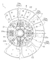
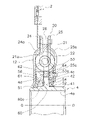
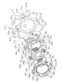
図1は、本発明の第1実施形態によるダンパ装置を有するクラッチディスク組立体の断面図である。図1のO-O線は、クラッチディスク組立体1の回転軸線である。このクラッチディスク組立体1は、図1の左側に配置されるエンジン及びフライホイールからのトルクを、図1の右側に配置されるトランスミッションに伝達し、かつトルク変動を減衰する。また、図2はクラッチディスク組立体1の正面部分図である。 FIG. 1 is a cross-sectional view of a clutch disc assembly having a damper device according to the first embodiment of the present invention. The OO line in FIG. 1 is the rotation axis of the clutch disc assembly 1. The clutch disc assembly 1 transmits torque from the engine and flywheel located on the left side of FIG. 1 to a transmission arranged on the right side of FIG. 1 and attenuates torque fluctuations. Further, FIG. 2 is a front partial view of the clutch disc assembly 1.

[全体構成]
クラッチディスク組立体1は、摩擦係合によりフライホイールからトルクが入力されるクラッチディスク2と、クラッチディスク2から入力されるトルク変動を減衰及び吸収するダンパ機構3(ダンパ装置)と、スプラインハブ4と、を有している。
[overall structure]
The clutch disc assembly 1 includes a clutch disc 2 in which torque is input from a flywheel by frictional engagement, a damper mechanism 3 (damper device) that attenuates and absorbs torque fluctuations input from the clutch disc 2, and a spline hub 4. And have.

[クラッチディスク2]
クラッチディスク2は、図示しないプレッシャプレートによってフライホイールに押し付けられる。クラッチディスク2は、クッショニングプレート6と、クッショニングプレート6の両面にリベット7によって固定される1対の摩擦フェーシング8と、を有している。クッショニングプレート6はダンパ機構3の外周部に固定されている。
[Clutch disc 2]
The clutch disc 2 is pressed against the flywheel by a pressure plate (not shown). The clutch disc 2 has a cushioning plate 6 and a pair of friction facings 8 fixed to both sides of the cushioning plate 6 by rivets 7. The cushioning plate 6 is fixed to the outer peripheral portion of the damper mechanism 3.

[ダンパ機構3]
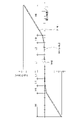
ダンパ機構3は、エンジンから伝達されるトルク変動を効果的に減衰及び吸収するために、図3に示すように、正側(駆動側の回転方向)及び負側において4段の捩り特性を有している。具体的には、捩り特性の正側及び負側において、1段目(L1)領域及び2段目(L2)領域は低捩り剛性及び低ヒステリシストルクの領域であり、3段目(H3)領域及び4段目(H4)領域は高捩り剛性及び高ヒステリシストルクの領域である。
[Damper mechanism 3]
As shown in FIG. 3, the damper mechanism 3 has four stages of torsional characteristics on the positive side (rotational direction on the drive side) and the negative side in order to effectively attenuate and absorb torque fluctuations transmitted from the engine. are doing. Specifically, on the positive and negative sides of the torsional characteristics, the first stage (L1) region and the second stage (L2) region are regions of low torsional rigidity and low hysteresis torque, and the third stage (H3) region. The fourth stage (H4) region is a region of high torsional rigidity and high hysteresis torque.

ダンパ機構3は、低剛性ダンパ11と、高剛性ダンパ12と、全領域ヒステリシストルク発生機構(以下、「L-Hヒス発生機構」と記す)13(第2ヒステリシストルク発生機構の一例)と、低捩り角度領域ヒステリシストルク発生機構(以下、「Lヒス発生機構」と記す)14と、中捩り角度領域ヒステリシストルク発生機構(以下、「L2ヒス発生機構」と記す)15と、高捩り角度領域ヒステリシストルク発生機構(以下、「Hヒス発生機構」と記す)16(第1ヒステリシストルク発生機構の一例)と、ストッパ機構17と、を有している。 The damper mechanism 3 includes a low-rigidity damper 11, a high-rigidity damper 12, an all-region hysteresis torque generation mechanism (hereinafter referred to as “LH hiss generation mechanism”) 13 (an example of a second hysteresis torque generation mechanism), and a second hysteresis torque generation mechanism. Low torsion angle region hysteresis torque generation mechanism (hereinafter referred to as "L hiss generation mechanism") 14, medium torsion angle region hysteresis torque generation mechanism (hereinafter referred to as "L2 hiss generation mechanism") 15, and high torsion angle region It has a hysteresis torque generation mechanism (hereinafter referred to as “H hiss generation mechanism”) 16 (an example of a first hysteresis torque generation mechanism) and a stopper mechanism 17.

低剛性ダンパ11は、低捩り角度領域(L1+L2)で作動する。高剛性ダンパ12は、低捩り角度領域よりも捩り角度の大きい高捩り角度領域(H3+H4)で作動する。また、高剛性ダンパ12は低剛性ダンパ11よりも高い捩り剛性を有する。 The low-rigidity damper 11 operates in a low torsional angle region (L1 + L2). The high-rigidity damper 12 operates in a high torsional angle region (H3 + H4) in which the torsional angle is larger than the low torsional angle region. Further, the high-rigidity damper 12 has a higher torsional rigidity than the low-rigidity damper 11.

L-Hヒス発生機構13は、低捩り角度領域(L1+L2)及び高捩り角度領域(H3+H4)の全捩り角度領域においてヒステリシストルクを発生する機構である。Lヒス発生機構14は、低捩り角度領域の全領域(L1+L2)でのみヒステリシストルクを発生する機構である。L2ヒス発生機構15は、2段目の第2捩り角度領域(L2)でのみヒステリシストルクを発生する機構である。Hヒス発生機構16は、高捩り角度領域(H3+H4)でのみヒステリシストルクを発生する機構である。 The LH hiss generation mechanism 13 is a mechanism that generates a hysteresis torque in the entire torsion angle region of the low torsion angle region (L1 + L2) and the high torsion angle region (H3 + H4). The L hiss generation mechanism 14 is a mechanism that generates a hysteresis torque only in the entire region (L1 + L2) of the low twist angle region. The L2 hiss generation mechanism 15 is a mechanism that generates a hysteresis torque only in the second twist angle region (L2) of the second stage. The H hiss generation mechanism 16 is a mechanism that generates a hysteresis torque only in a high torsional angle region (H3 + H4).

ストッパ機構17は、入力側の部材であるクラッチディスク2と、出力側の部材であるスプラインハブ4と、の捩り角度(相対回転角度)が所定の角度になると、それ以上の両部材の相対回転角度を禁止する機構である。 When the twist angle (relative rotation angle) of the clutch disc 2 which is a member on the input side and the spline hub 4 which is a member on the output side becomes a predetermined angle, the stopper mechanism 17 further rotates the relative rotation of both members. It is a mechanism that prohibits angles.

<高剛性ダンパ12>
高剛性ダンパ12は、図4に示すように、入力側回転部材20(第1回転部材の一例)と、ハブフランジ21と、複数の高剛性スプリング22と、を有している。
<High rigidity damper 12>
As shown in FIG. 4, the high-rigidity damper 12 has an input-side rotating member 20 (an example of a first rotating member), a hub flange 21, and a plurality of high-rigidity springs 22.

-入力側回転部材20-
入力側回転部材20には、クラッチディスク2を介してエンジンからトルクが入力され、クラッチプレート24(第1プレートの一例)及びリティニングプレート25を有している。
-Input side rotating member 20-
Torque is input to the input-side rotating member 20 from the engine via the clutch disc 2, and has a clutch plate 24 (an example of a first plate) and a leaning plate 25.

クラッチプレート24及びリティニングプレート25は、実質的に環状に形成され、軸方向に間隔を隔てて配置されている。クラッチプレート24はエンジン側に配置され、リティニングプレート25はトランスミッション側に配置されている。クラッチプレート24及びリティニングプレート25は、外周部がストップピン26によって連結されており、一体で回転する。 The clutch plate 24 and the subtraction plate 25 are formed in a substantially annular shape and are arranged at intervals in the axial direction. The clutch plate 24 is arranged on the engine side, and the leaning plate 25 is arranged on the transmission side. The outer peripheral portion of the clutch plate 24 and the subtraction plate 25 are connected by a stop pin 26 and rotate integrally.

クラッチプレート24及びリティニングプレート25には、図2に示すように、それぞれ4個の第1保持部24a,25a及び第2保持部24b,25bが円周方向に間隔を隔てて形成されている。第1保持部24a,25aと第2保持部24b,25bとは円周方向に交互に配置されている。また、リティニングプレート25には、複数の係合孔25cが形成されている。 As shown in FIG. 2, four first holding portions 24a and 25a and second holding portions 24b and 25b are formed on the clutch plate 24 and the subtraction plate 25 at intervals in the circumferential direction, respectively. .. The first holding portions 24a and 25a and the second holding portions 24b and 25b are alternately arranged in the circumferential direction. Further, a plurality of engaging holes 25c are formed in the reinforcement plate 25.

なお、図2では、リティニングプレート25を示しているが、各保持部24a,24b,24b,25bに関しては、逆側に配置されたクラッチプレート24も同様の構成である。また、図2では、リティニングプレート25の一部を破断して示している。 Although the thinning plate 25 is shown in FIG. 2, the clutch plates 24 arranged on the opposite sides of the holding portions 24a, 24b, 24b, and 25b have the same configuration. Further, in FIG. 2, a part of the linting plate 25 is broken and shown.

-ハブフランジ21-
ハブフランジ21は、略円板状の部材であり(図7参照)、スプラインハブ4の外周に配置されている。ハブフランジ21は、クラッチプレート24とリティニングプレート25との軸方向間に配置され、これらの両プレート24,25と所定の角度範囲内で相対回転可能である。図5に示すように、ハブフランジ21とスプラインハブ4とは、互いの内周部及び外周部に形成された複数の歯21c,4cによって噛み合っている。すなわち、ハブフランジ21とスプラインハブ4とが第2回転部材の一例である。なお、互いの歯21c,4cの間には所定の隙間G1が設定されている。すなわち、ハブフランジ21とスプラインハブ4とは、歯21c,4cの隙間G1の角度分(低捩り角度領域(L1+L2)に相当)だけ相対回転が可能である。
-Hub flange 21-
The hub flange 21 is a substantially disk-shaped member (see FIG. 7), and is arranged on the outer periphery of the spline hub 4. The hub flange 21 is arranged between the clutch plate 24 and the reinforcement plate 25 in the axial direction, and can rotate relative to both the plates 24 and 25 within a predetermined angle range. As shown in FIG. 5, the hub flange 21 and the spline hub 4 are meshed with each other by a plurality of teeth 21c and 4c formed on the inner peripheral portion and the outer peripheral portion of each other. That is, the hub flange 21 and the spline hub 4 are examples of the second rotating member. A predetermined gap G1 is set between the teeth 21c and 4c. That is, the hub flange 21 and the spline hub 4 can rotate relative to each other by the angle of the gap G1 between the teeth 21c and 4c (corresponding to the low twist angle region (L1 + L2)).

ハブフランジ21には、図5に示すように、クラッチプレート24及びリティニングプレート25の第1保持部24a,25a及び第2保持部24b,25bと対向する位置に、それぞれ第1窓孔21a及び第2窓孔21bが形成されている。そして、第1窓孔21aに第1高剛性スプリング22aが収容され、この第1高剛性スプリング22aがクラッチプレート24及びリティニングプレート25の第1保持部24a,25aによって軸方向及び径方向に保持されている。また、第2窓孔21bに第2高剛性スプリング22bが収容され、この第2高剛性スプリング22bがクラッチプレート24及びリティニングプレート25の第2保持部24b,25bによって軸方向及び径方向に保持されている。 As shown in FIG. 5, the hub flange 21 has a first window hole 21a and a position facing the first holding portions 24a and 25a and the second holding portions 24b and 25b of the clutch plate 24 and the leaning plate 25, respectively. The second window hole 21b is formed. Then, the first high-rigidity spring 22a is housed in the first window hole 21a, and the first high-rigidity spring 22a is held axially and radially by the first holding portions 24a and 25a of the clutch plate 24 and the leaning plate 25. Has been done. Further, a second high-rigidity spring 22b is housed in the second window hole 21b, and the second high-rigidity spring 22b is held in the axial direction and the radial direction by the second holding portions 24b and 25b of the clutch plate 24 and the reinforcement plate 25. Has been done.

なお、クラッチプレート24及びリティニングプレート25の第1保持部24a,25a及び第2保持部24b,25bの円周方向の両端は、各高剛性スプリング22a,22bの端面に係合可能である。 Both ends of the first holding portions 24a, 25a and the second holding portions 24b, 25b of the clutch plate 24 and the reinforcement plate 25 in the circumferential direction can be engaged with the end faces of the high-rigidity springs 22a, 22b.

ここで、ハブフランジ21の第1窓孔21aには第1高剛性スプリング22aが、第2窓孔21bには第2高剛性スプリング22bが、それぞれ円周方向に隙間なく配置されている。一方、クラッチプレート24及びリティニングプレート25の第1保持部24a,25aには第1高剛性スプリング22aが円周方向に隙間なく配置されているが、両プレート24,25の第2保持部24b,25bには、第2高剛性スプリング22bが円周方向に隙間G2(図2及び図5参照)を介して配置されている。この隙間G2が3段目の捩り角度分(角度領域H3)に相当している。 Here, the first high-rigidity spring 22a is arranged in the first window hole 21a of the hub flange 21, and the second high-rigidity spring 22b is arranged in the second window hole 21b without any gap in the circumferential direction. On the other hand, the first high-rigidity springs 22a are arranged on the first holding portions 24a and 25a of the clutch plate 24 and the reinforcement plate 25 without gaps in the circumferential direction, but the second holding portions 24b of both plates 24 and 25 are arranged. At 25b, a second high-rigidity spring 22b is arranged in the circumferential direction via a gap G2 (see FIGS. 2 and 5). This gap G2 corresponds to the twist angle of the third stage (angle region H3).

なお、ハブフランジ21の第2窓孔21bのそれぞれの内周側には、軸方向に貫通する係合孔21eが形成されている。 An engaging hole 21e penetrating in the axial direction is formed on the inner peripheral side of each of the second window holes 21b of the hub flange 21.

以上の構成により、詳細は後述するが、高捩り角度領域H3,H4では、まず第1高剛性スプリング22aのみが圧縮され(H3領域)、その後、第1高剛性スプリング22aに加えて第2高剛性スプリング22bが圧縮される(H4領域)ことになる。 With the above configuration, although details will be described later, in the high torsion angle regions H3 and H4, only the first high-rigidity spring 22a is first compressed (H3 region), and then the second height is added to the first high-rigidity spring 22a. The rigid spring 22b is compressed (H4 region).

<ストッパ機構17>
ストッパ機構17は、図5に示すように、ハブフランジ21の外周部に形成された複数のストッパ用切欠21dと、前述のストップピン26と、から構成されている。ストッパ用切欠21dは、所定の角度範囲にわたって形成されており、径方向外方に開いている。そして、このストッパ用切欠21dをストップピン26が軸方向に貫通している。
<Stopper mechanism 17>
As shown in FIG. 5, the stopper mechanism 17 is composed of a plurality of stopper notches 21d formed on the outer peripheral portion of the hub flange 21 and the above-mentioned stop pin 26. The stopper notch 21d is formed over a predetermined angular range and is radially outwardly open. The stop pin 26 penetrates the stopper notch 21d in the axial direction.

また、切欠21dは、円周方向の両端部が内周側に向かって深く形成され、中央部分が浅く形成されている。この浅い部分の内周側に、第2窓孔21bが形成されている。 Further, in the notch 21d, both end portions in the circumferential direction are formed deeply toward the inner peripheral side, and the central portion is formed shallowly. A second window hole 21b is formed on the inner peripheral side of this shallow portion.

<低剛性ダンパ11>
低剛性ダンパ11は、図6及び図7に示すように、サブプレート34及びスプリングホルダ35と、ドライブプレート36と、複数の低剛性スプリング37と、を有している。
<Low rigidity damper 11>
As shown in FIGS. 6 and 7, the low-rigidity damper 11 has a sub-plate 34, a spring holder 35, a drive plate 36, and a plurality of low-rigidity springs 37.

-サブプレート34-
サブプレート34は、クラッチプレート24とハブフランジ21との軸方向間に配置され、ほぼ矩形であって、角部が円弧状に形成されている。サブプレート34は、図7に示すように、中央部に円形の開口を有しており、それぞれ2個の第1保持部34a及び第2保持部34bと、4個の第1係合突起34cと、第1係合突起34cより突起長さが短い4個の第2係合突起34dと、環状溝34eと、を有している。
-Sub-plate 34-
The sub-plate 34 is arranged between the clutch plate 24 and the hub flange 21 in the axial direction, is substantially rectangular, and has corners formed in an arc shape. As shown in FIG. 7, the sub-plate 34 has a circular opening in the central portion, and has two first holding portions 34a and a second holding portion 34b, and four first engaging protrusions 34c, respectively. And four second engaging protrusions 34d having a protrusion length shorter than that of the first engaging protrusion 34c, and an annular groove 34e.

第1保持部34a及び第2保持部34bは、各係合突起34cの内周側に形成されている。4個の第1係合突起34cは、4つの角部外周にハブフランジ21側に突出して形成されている。環状溝34eは第1保持部34a及び第2保持部34bの内周側で、開口部の縁に形成されている。 The first holding portion 34a and the second holding portion 34b are formed on the inner peripheral side of each engaging protrusion 34c. The four first engaging protrusions 34c are formed so as to project toward the hub flange 21 on the outer periphery of the four corners. The annular groove 34e is formed on the inner peripheral side of the first holding portion 34a and the second holding portion 34b at the edge of the opening.

-スプリングホルダ35-
スプリングホルダ35は、サブプレート34とハブフランジ21との軸方向間で、サブプレート34と間隔をあけて対向して配置されている。スプリングホルダ35はサブプレート34とほぼ同様の形状である。スプリングホルダ35は、中央部に円形の開口を有しており、それぞれ2個の第1保持部35a及び第2保持部35bと、4個のボス部35cと、4個の切欠35dと、を有している。各ボス部35cには切欠35eが形成されている。また、第2保持部35bの円周方向両端には、円周方向に延びる円弧状溝35fが形成されている。
-Spring holder 35-
The spring holder 35 is arranged so as to face the sub-plate 34 at a distance from the sub-plate 34 in the axial direction between the sub-plate 34 and the hub flange 21. The spring holder 35 has almost the same shape as the sub plate 34. The spring holder 35 has a circular opening in the central portion, and has two first holding portions 35a and a second holding portion 35b, four boss portions 35c, and four notches 35d, respectively. Have. A notch 35e is formed in each boss portion 35c. Further, arcuate grooves 35f extending in the circumferential direction are formed at both ends of the second holding portion 35b in the circumferential direction.

第1保持部35a及び第2保持部35bは、それぞれサブプレート34の第1保持部34a及び第2保持部34bと対向する位置に形成されている。4個のボス部35cは、4つの角部外周に形成されている。この4個のボス部35cの切欠35eにサブプレート34の第1係合突起34cが係合し、さらにボス部35cがハブフランジ21の係合孔21eに係合している。このように、第1係合突起34c及びボス部35cが係合孔21eに圧入されることで、サブプレート34はハブフランジ21に対して軸方向に移動不能になっている。また、切欠35dは、サブプレート34の第2係合突起34dに対応して形成されており、この切欠35dに第2係合突起34dが係合している。 The first holding portion 35a and the second holding portion 35b are formed at positions facing the first holding portion 34a and the second holding portion 34b of the sub-plate 34, respectively. The four boss portions 35c are formed on the outer circumferences of the four corner portions. The first engaging projection 34c of the sub-plate 34 is engaged with the notches 35e of the four boss portions 35c, and the boss portion 35c is further engaged with the engaging hole 21e of the hub flange 21. As described above, the first engaging protrusion 34c and the boss portion 35c are press-fitted into the engaging hole 21e, so that the sub-plate 34 cannot move in the axial direction with respect to the hub flange 21. Further, the notch 35d is formed corresponding to the second engaging protrusion 34d of the sub-plate 34, and the second engaging protrusion 34d is engaged with the notch 35d.

なお、サブプレート34の第1係合突起34cは先端に爪を有していてもよい。この場合、第1係合突起34cの先端部は、切欠35e及びハブフランジ21の係合孔21eを貫通し、先端の爪がハブフランジ21の側面に係合する。これにより、サブプレート34はハブフランジ21に対して軸方向に移動不能となる。 The first engaging projection 34c of the sub-plate 34 may have a claw at its tip. In this case, the tip portion of the first engaging protrusion 34c penetrates the notch 35e and the engaging hole 21e of the hub flange 21, and the claw at the tip engages with the side surface of the hub flange 21. As a result, the sub-plate 34 becomes immovable in the axial direction with respect to the hub flange 21.

以上のように、サブプレート34とスプリングホルダ35とが、第1係合突起34cと切欠35eとの係合、及び第2係合突起34dと切欠35dとの係合、によって一体化されている。そして、スプリングホルダ35とハブフランジ21とが、第1係合突起34c及びボス部35cと係合孔21eとの係合によって一体化されている。したがって、サブプレート34及びスプリングホルダ35はハブフランジ21と一体に回転する。 As described above, the sub-plate 34 and the spring holder 35 are integrated by the engagement between the first engaging protrusion 34c and the notch 35e and the engagement between the second engaging protrusion 34d and the notch 35d. .. The spring holder 35 and the hub flange 21 are integrated by engaging the first engaging protrusion 34c, the boss portion 35c, and the engaging hole 21e. Therefore, the sub-plate 34 and the spring holder 35 rotate integrally with the hub flange 21.

-ドライブプレート36-
ドライブプレート36は、サブプレート34とスプリングホルダ35との軸方向間に配置され、サブプレート34及びスプリングホルダ35と所定の角度範囲内で相対回転可能である。ドライブプレート36は、中央部に開口を有しており、それぞれ2個の第1窓孔36a及び第2窓孔36bと、ドライブプレート36の内周面に形成された複数の係合凹部36cと、を有している。
-Drive plate 36-
The drive plate 36 is arranged between the sub-plate 34 and the spring holder 35 in the axial direction, and can rotate relative to the sub-plate 34 and the spring holder 35 within a predetermined angle range. The drive plate 36 has an opening in the central portion, and has two first window holes 36a and a second window hole 36b, respectively, and a plurality of engaging recesses 36c formed on the inner peripheral surface of the drive plate 36. ,have.

また、第1窓孔36aの内周端部の両側には、それぞれ円周方向に延びる第1係合溝36dが形成されている。第2窓孔36bの内周端部の一方側には、円周方向に延びる第2係合溝36eが形成されている。 Further, first engaging grooves 36d extending in the circumferential direction are formed on both sides of the inner peripheral end portion of the first window hole 36a. A second engaging groove 36e extending in the circumferential direction is formed on one side of the inner peripheral end portion of the second window hole 36b.

第1窓孔36a及び第2窓孔36bは、それぞれサブプレート34及びスプリングホルダ35の第1保持部34a,35a及び第2保持部34b,35bと対向する位置に形成されている。そして、第1窓孔36aに第1低剛性スプリング37aが収容され、この第1低剛性スプリング37aがサブプレート34及びスプリングホルダ35の第1保持部34a,35aによって軸方向及び径方向に保持されている。また、第2窓孔36bに第2低剛性スプリング37bが収容され、この第2低剛性スプリング37bがサブプレート34及びスプリングホルダ35の第2保持部34b,35bによって軸方向及び径方向に保持されている。 The first window hole 36a and the second window hole 36b are formed at positions facing the first holding portions 34a and 35a and the second holding portions 34b and 35b of the sub-plate 34 and the spring holder 35, respectively. A first low-rigidity spring 37a is housed in the first window hole 36a, and the first low-rigidity spring 37a is held axially and radially by the sub-plate 34 and the first holding portions 34a and 35a of the spring holder 35. ing. Further, a second low-rigidity spring 37b is housed in the second window hole 36b, and the second low-rigidity spring 37b is held axially and radially by the sub-plate 34 and the second holding portions 34b and 35b of the spring holder 35. ing.

なお、サブプレート34及びスプリングホルダ35の第1保持部34a,35a及び第2保持部34b,35bの円周方向の両端は、各低剛性スプリング37a,37bの端面に係合可能である。 Both ends of the first holding portions 34a, 35a and the second holding portions 34b, 35b of the sub-plate 34 and the spring holder 35 in the circumferential direction can be engaged with the end faces of the low-rigidity springs 37a, 37b.

ここで、ドライブプレート36の第1窓孔36aには第1低剛性スプリング37aが、第2窓孔36bには第2低剛性スプリング37bが、それぞれ円周方向に隙間なく配置されている。一方、サブプレート34及びスプリングホルダ35の第1保持部34a,35aには第1低剛性スプリング37aが円周方向に隙間なく配置されているが、両部材34,35の第2保持部34b,35bには、第2低剛性スプリング37bが円周方向に隙間を介して配置されている。この隙間が1段目の捩り角度分(低捩り角度領域L1)に相当している。 Here, the first low-rigidity spring 37a is arranged in the first window hole 36a of the drive plate 36, and the second low-rigidity spring 37b is arranged in the second window hole 36b without any gap in the circumferential direction. On the other hand, although the first low-rigidity spring 37a is arranged in the first holding portions 34a and 35a of the sub-plate 34 and the spring holder 35 without any gap in the circumferential direction, the second holding portions 34b of both members 34 and 35, A second low-rigidity spring 37b is arranged in the 35b with a gap in the circumferential direction. This gap corresponds to the twist angle of the first stage (low twist angle region L1).

低剛性スプリング37のバネ定数は、高剛性スプリング22のバネ定数に比べて大幅に小さく設定されている。すなわち、高剛性スプリング22は低剛性スプリング37よりもはるかに剛性が高い。このため、1段目領域(L1)及び2段目領域(L2)では、高剛性スプリング22は圧縮されず、低剛性スプリング37のみが圧縮される。 The spring constant of the low-rigidity spring 37 is set to be significantly smaller than the spring constant of the high-rigidity spring 22. That is, the high-rigidity spring 22 is much more rigid than the low-rigidity spring 37. Therefore, in the first-stage region (L1) and the second-stage region (L2), the high-rigidity spring 22 is not compressed, and only the low-rigidity spring 37 is compressed.

[スプラインハブ4]
スプラインハブ4は、クラッチプレート24及びリティニングプレート25の内周側に配置されている。スプラインハブ4は、図4及び図6に示すように、軸方向に延びる筒状のボス41と、ボス41から径方向外側に延びるフランジ42と、を有している。ボス41の内周部には、トランスミッションの入力シャフト(図示せず)に係合するスプライン孔4aが形成されている。
[Spline Hub 4]
The spline hub 4 is arranged on the inner peripheral side of the clutch plate 24 and the reinforcement plate 25. As shown in FIGS. 4 and 6, the spline hub 4 has a cylindrical boss 41 extending in the axial direction and a flange 42 extending radially outward from the boss 41. A spline hole 4a that engages with an input shaft (not shown) of a transmission is formed in the inner peripheral portion of the boss 41.

ボス41の外周面において、フランジ42のエンジン側には複数の係合凸部4dが形成されている。係合凸部4dはドライブプレート36の係合凹部36cに、実質的に隙間なく係合している。また、フランジ42の外周面には、歯4cが形成されている。図5で説明したように、この歯4cが、ハブフランジ21の歯21cと噛合可能であり、両歯4c,21cの円周方向間には隙間G1が存在する。 On the outer peripheral surface of the boss 41, a plurality of engaging protrusions 4d are formed on the engine side of the flange 42. The engaging convex portion 4d is engaged with the engaging concave portion 36c of the drive plate 36 substantially without a gap. Further, teeth 4c are formed on the outer peripheral surface of the flange 42. As described with reference to FIG. 5, this tooth 4c can mesh with the tooth 21c of the hub flange 21, and a gap G1 exists between the circumferential directions of both teeth 4c and 21c.

<L-Hヒス発生機構13>
L-Hヒス発生機構13は、捩り角度領域の全領域(L1+L2+H3+H4)においてヒステリシストルクHを発生する。
<LH hiss generation mechanism 13>
The LH hiss generation mechanism 13 generates the hysteresis torque H in the entire region (L1 + L2 + H3 + H4) of the twist angle region.

L-Hヒス発生機構13は、図6に示すように、第1摩擦ワッシャ51(第1摩擦部材の一例)と、第2摩擦ワッシャ52と、第1コーンスプリング54と、を有している。 As shown in FIG. 6, the LH hiss generating mechanism 13 has a first friction washer 51 (an example of a first friction member), a second friction washer 52, and a first cone spring 54. ..

第1摩擦ワッシャ51は、樹脂製であり、スプラインハブ4のボス41の外周において、係合凸部4dの側面とクラッチプレート24の内周端部との間に配置されている。より詳細には、第1摩擦ワッシャ51の外周面において、クラッチプレート24側の角部は、軸方向の外側(クラッチプレート24側)に向かって径が小さくなる傾斜面51aとなっている。また、クラッチプレート24の内周端面は、この傾斜面51aに当接する傾斜面24cとなっている。 The first friction washer 51 is made of resin and is arranged on the outer periphery of the boss 41 of the spline hub 4 between the side surface of the engaging convex portion 4d and the inner peripheral end portion of the clutch plate 24. More specifically, on the outer peripheral surface of the first friction washer 51, the corner portion on the clutch plate 24 side is an inclined surface 51a whose diameter decreases toward the outside in the axial direction (clutch plate 24 side). Further, the inner peripheral end surface of the clutch plate 24 is an inclined surface 24c that abuts on the inclined surface 51a.

第2摩擦ワッシャ52は、樹脂製であり、スプラインハブ4のフランジ42とリティニングプレート25の内周端部との軸方向間に配置されている。第2摩擦ワッシャ52の外周部には、後述する第3摩擦ワッシャ53に係合する係合部(図示せず)を有しており、両部材は一体回転する。 The second friction washer 52 is made of resin and is arranged between the flange 42 of the spline hub 4 and the inner peripheral end portion of the linting plate 25 in the axial direction. The outer peripheral portion of the second friction washer 52 has an engaging portion (not shown) that engages with the third friction washer 53, which will be described later, and both members rotate integrally.

また、第1コーンスプリング54は、第2摩擦ワッシャ52とリティニングプレート25の内周端部との軸方向間に配置され、第2摩擦ワッシャ52とリティニングプレート25とが互いに離れるように、両部材25,52を付勢している。 Further, the first cone spring 54 is arranged between the second friction washer 52 and the inner peripheral end portion of the linting plate 25 in the axial direction so that the second friction washer 52 and the linting plate 25 are separated from each other. Both members 25 and 52 are urged.

以上から、クラッチプレート24及びリティニングプレート25と、スプラインハブ4と、が相対回転する全捩り角度領域において、第1摩擦ワッシャ51とクラッチプレート24又はスプラインハブ4との間に摩擦抵抗が発生するとともに、第2摩擦ワッシャ52とスプラインハブ4との間に摩擦抵抗が発生する。これらの摩擦抵抗によって、全捩り角度領域においてヒステリシストルクHが発生する。 From the above, frictional resistance is generated between the first friction washer 51 and the clutch plate 24 or the spline hub 4 in the total twist angle region where the clutch plate 24, the leaning plate 25, and the spline hub 4 rotate relative to each other. At the same time, frictional resistance is generated between the second friction washer 52 and the spline hub 4. Due to these frictional resistances, a hysteresis torque H is generated in the entire torsion angle region.

<Lヒス発生機構14>
Lヒス発生機構14は、1段目領域及び2段目領域である低捩り角度領域の全領域(L1+L2)でのみヒステリシストルクhLを発生する。
<L hiss generation mechanism 14>
The L hiss generation mechanism 14 generates the hysteresis torque hL only in the entire region (L1 + L2) of the low twist angle region, which is the first stage region and the second stage region.

Lヒス発生機構14は、図7に示すように、サブプレート34の環状溝34eに装着された付勢部材としての波線56を有している。波線56は、一部に欠落部を有する環状の線材で形成されている。波線56は、円周方向に所定の間隔で複数の押圧部56aを有している。押圧部56aはドライブプレート36側に突出して形成されており、弾性変形が可能である。また、押圧部56aの先端部は、ドライブプレート36の各窓孔36a,36bに形成された第1及び第2係合溝36d,36eに係合可能である。このように、波線56は、ドライブプレート36に対して相対回転不能であり、かつ環状溝34e内で円周方向に移動可能である。そして、波線56の弾性変形によって、ドライブプレート36がスプリングホルダ35側に付勢されている。 As shown in FIG. 7, the L-his generation mechanism 14 has a wavy line 56 as an urging member mounted on the annular groove 34e of the sub-plate 34. The wavy wire 56 is formed of an annular wire rod having a partially missing portion. The wavy line 56 has a plurality of pressing portions 56a at predetermined intervals in the circumferential direction. The pressing portion 56a is formed so as to project toward the drive plate 36 side, and can be elastically deformed. Further, the tip portion of the pressing portion 56a can be engaged with the first and second engaging grooves 36d and 36e formed in the window holes 36a and 36b of the drive plate 36. As described above, the wavy line 56 cannot rotate relative to the drive plate 36 and can move in the circumferential direction in the annular groove 34e. Then, the drive plate 36 is urged toward the spring holder 35 by the elastic deformation of the wavy line 56.

ここで、前述のように、サブプレート34及びスプリングホルダ35はハブフランジ21と一体回転する。また、ドライブプレート36はスプラインハブ4と一体回転する。そして、ハブフランジ21とスプラインハブ4とは、前述のように、隙間G1の角度分だけ相対回転可能である。言い換えれば、ハブフランジ21(スプリングホルダ35と一体回転)とスプラインハブ4(ドライブプレート36と一体回転)とは、捩り特性の1段目領域と2段目領域の低捩り角度領域の全領域(L1+L2)においてのみ相対回転可能である。 Here, as described above, the sub-plate 34 and the spring holder 35 rotate integrally with the hub flange 21. Further, the drive plate 36 rotates integrally with the spline hub 4. As described above, the hub flange 21 and the spline hub 4 can rotate relative to each other by the angle of the gap G1. In other words, the hub flange 21 (integral rotation with the spring holder 35) and the spline hub 4 (integral rotation with the drive plate 36) are the entire region of the low torsion angle region of the first stage region and the second stage region of the torsion characteristics (integral rotation with the spring holder 35). Relative rotation is possible only in L1 + L2).

そして、スプリングホルダ35とドライブプレート36とは、波線56によって互いに押圧されているので、スプリングホルダ35とドライブプレート36とは低捩り角度の全領域(L1+L2)においてのみ相対回転して摩擦抵抗が生じる。また、波線56とサブプレート34の環状溝34eの底部との間にも摩擦抵抗が生じる。これらの摩擦抵抗によって、ヒステリシストルクhLが発生する。 Since the spring holder 35 and the drive plate 36 are pressed against each other by the wavy line 56, the spring holder 35 and the drive plate 36 rotate relative to each other only in the entire region (L1 + L2) having a low twist angle, and frictional resistance is generated. .. Further, frictional resistance is also generated between the wavy line 56 and the bottom of the annular groove 34e of the sub-plate 34. Hysteresis torque hL is generated by these frictional resistances.

ここでは、サブプレート34の環状溝34eに波線56が埋め込まれるように装着されているので、軸方向寸法を抑えて、ヒステリシストルク発生機構を実現できる。また、スプリングホルダ35とドライブプレート36との間だけではなく、波線56とサブプレート34の環状溝34eの底部との間にも摩擦抵抗が生じるので、各部における摩擦抵抗を小さくして所望のヒステリシストルクが得られる。したがって、各部の磨耗を抑えることができる。 Here, since the wavy line 56 is embedded in the annular groove 34e of the sub-plate 34, the axial dimension can be suppressed and the hysteresis torque generation mechanism can be realized. Further, since frictional resistance is generated not only between the spring holder 35 and the drive plate 36 but also between the wavy line 56 and the bottom of the annular groove 34e of the sub-plate 34, the frictional resistance in each part is reduced to obtain a desired hysteresis. Torque is obtained. Therefore, wear of each part can be suppressed.

<L2ヒス発生機構15>
L2ヒス発生機構15は、2段目の捩り角度領域(L2)でのみヒステリシストルクhL2を発生する。
<L2 hiss generation mechanism 15>
The L2 hiss generation mechanism 15 generates the hysteresis torque hL2 only in the twist angle region (L2) of the second stage.

L2ヒス発生機構15はウェーブスプリング60を有している。ウェーブスプリング60は、軸方向に弾性変形可能な環状の弾性体であり、軸方向に圧縮された状態でスプラインハブ4のフランジ42とスプリングホルダ35との間に配置されている。ウェーブスプリング60は、ハブフランジ21及びスプリングホルダ35に当接しており、ハブフランジ21に対して回転すると摩擦抵抗を発生する。 The L2 hiss generating mechanism 15 has a wave spring 60. The wave spring 60 is an annular elastic body that can be elastically deformed in the axial direction, and is arranged between the flange 42 of the spline hub 4 and the spring holder 35 in a state of being compressed in the axial direction. The wave spring 60 is in contact with the hub flange 21 and the spring holder 35, and when rotated with respect to the hub flange 21, frictional resistance is generated.

図8に、ウェーブスプリング60及びその周辺の部材を抽出して示している。ウェーブスプリング60は、環状の本体部60aと、本体部60aから径方向外側へ延びる2対の爪部60bと、を有している。爪部60bの先端部は、軸方向に折り曲げられており、スプリングホルダ35に形成された円弧状溝35fを通過して第2低剛性スプリング37bの両端部に当接している。2つの爪部60b間の円周方向の距離は、第2低剛性スプリング37bの自由長とほぼ一致している。これにより、第2低剛性スプリング37bによりウェーブスプリング60の円周(回転)方向の位置決めが行われるとともに、第2低剛性スプリング37b及びウェーブスプリング60は一体で回転可能となっている。なお、溝35fの円周方向の距離は、2つの爪部60b間の円周方向の距離より長い。 FIG. 8 shows the wave spring 60 and its peripheral members extracted. The wave spring 60 has an annular main body portion 60a and two pairs of claw portions 60b extending radially outward from the main body portion 60a. The tip of the claw portion 60b is bent in the axial direction, passes through the arcuate groove 35f formed in the spring holder 35, and abuts on both ends of the second low-rigidity spring 37b. The circumferential distance between the two claws 60b is substantially the same as the free length of the second low-rigidity spring 37b. As a result, the second low-rigidity spring 37b positions the wave spring 60 in the circumferential (rotational) direction, and the second low-rigidity spring 37b and the wave spring 60 can rotate integrally. The distance in the circumferential direction of the groove 35f is longer than the distance in the circumferential direction between the two claw portions 60b.

また、本体部60aの内周部には、複数の係合凹部60cが形成されている。係合凹部60cは、スプラインハブ4の係合凸部4dに所定の隙間を介して係合している。この隙間が、1段目の捩り角度領域(L1)の角度分に相当している。したがって、1段目領域ではウェーブスプリング60によるヒステリシストルクは発生しないが、2段目領域(L2)でのみウェーブスプリング60によるヒステリシストルクhL2が得られる。 Further, a plurality of engaging recesses 60c are formed in the inner peripheral portion of the main body portion 60a. The engaging recess 60c is engaged with the engaging convex portion 4d of the spline hub 4 via a predetermined gap. This gap corresponds to the angle of the twist angle region (L1) of the first stage. Therefore, the hysteresis torque due to the wave spring 60 is not generated in the first stage region, but the hysteresis torque hL2 due to the wave spring 60 can be obtained only in the second stage region (L2).

<Hヒス発生機構16>
Hヒス発生機構16は、3段目領域及び4段目領域である高捩り角度領域(H3+H4)でのみヒステリシストルクhHを発生する。
<H hiss generation mechanism 16>
The H hiss generation mechanism 16 generates the hysteresis torque hH only in the high torsion angle region (H3 + H4) which is the third stage region and the fourth stage region.

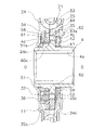
Hヒス発生機構16は、図4及び図6に示すように、サブプレート34に装着された環状の第1摩擦材61(サブプレート34及び第1摩擦材61が摩擦プレートの一例である)と、環状の第2摩擦材62を有する第3摩擦ワッシャ53と、第2コーンスプリング64と、を有している。 As shown in FIGS. 4 and 6, the H-his generation mechanism 16 includes an annular first friction material 61 mounted on the sub-plate 34 (the sub-plate 34 and the first friction material 61 are examples of the friction plate). , A third friction washer 53 having an annular second friction material 62, and a second cone spring 64.

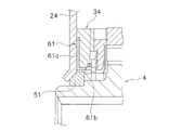
第1摩擦材61は、サブプレート34のエンジン側の側面に固定されており、サブプレート34とともにハブフランジ21と一体回転する。そして、第1摩擦材61は、クラッチプレート24の内周部の側面に当接可能である。また、第1摩擦材61は、図9に拡大して示すように、断面がL字状に形成されている。 The first friction material 61 is fixed to the side surface of the sub-plate 34 on the engine side, and rotates integrally with the hub flange 21 together with the sub-plate 34. The first friction material 61 can come into contact with the side surface of the inner peripheral portion of the clutch plate 24. Further, as shown in an enlarged view in FIG. 9, the first friction material 61 has an L-shaped cross section.

より詳細には、第1摩擦材61は、摩擦部61a及び緩衝部61b(緩衝部材の一例)を有している。第1摩擦材61は、例えば、熱可塑性エラストマー等の樹脂材料で形成されており、第1摩擦ワッシャ51よりも弾性が低く、かつ摩擦係数が大きい。また、第1摩擦材61は、Hヒス発生機構16を構成する他の部材よりも、高い輻射率を有している。 More specifically, the first friction material 61 has a friction portion 61a and a cushioning portion 61b (an example of a cushioning member). The first friction material 61 is made of a resin material such as a thermoplastic elastomer, and has lower elasticity and a larger friction coefficient than the first friction washer 51. Further, the first friction material 61 has a higher emissivity than the other members constituting the H hiss generation mechanism 16.

摩擦部61aは、クラッチプレート24の側面に摩擦接触する部分であり、円板状に形成されている。緩衝部61bは、摩擦部61aの内周端からリティニングプレート25側に軸方向に延びている。緩衝部61bは、第1摩擦ワッシャ51の外周面に対して、径方向に所定の隙間をあけて対向する位置に配置されている。 The friction portion 61a is a portion that comes into frictional contact with the side surface of the clutch plate 24, and is formed in a disk shape. The cushioning portion 61b extends axially from the inner peripheral end of the friction portion 61a toward the linting plate 25. The cushioning portion 61b is arranged at a position facing the outer peripheral surface of the first friction washer 51 with a predetermined gap in the radial direction.

第3摩擦ワッシャ53は、ハブフランジ21内周部とリティニングプレート25内周部との間に配置されており、リティニングプレート25側に突出する複数の係合突起53aを有している。この係合突起53aがリティニングプレート25の係合孔25cに係合している。したがって、第3摩擦ワッシャ53はリティニングプレート25と一体回転する。第2摩擦材62は、第3摩擦ワッシャ53のハブフランジ21側の側面に固定され、ハブフランジ21の内周部の側面に摩擦接触する。 The third friction washer 53 is arranged between the inner peripheral portion of the hub flange 21 and the inner peripheral portion of the linting plate 25, and has a plurality of engaging protrusions 53a protruding toward the linting plate 25 side. The engaging protrusion 53a is engaged with the engaging hole 25c of the linting plate 25. Therefore, the third friction washer 53 rotates integrally with the linting plate 25. The second friction material 62 is fixed to the side surface of the third friction washer 53 on the hub flange 21 side, and is in frictional contact with the side surface of the inner peripheral portion of the hub flange 21.

第2コーンスプリング64は、第3摩擦ワッシャ53とリティニングプレート25との間に配置されている。第2コーンスプリング64は、第3摩擦ワッシャ53とリティニングプレート25とを、両者が軸方向に互いに離れる方向に付勢している。したがって、第2コーンスプリング64により、第1摩擦材61とクラッチプレート24とが互いに押圧され、第2摩擦材62とハブフランジ21とが互いに押圧される。 The second cone spring 64 is arranged between the third friction washer 53 and the linting plate 25. The second cone spring 64 urges the third friction washer 53 and the linting plate 25 in a direction in which they are axially separated from each other. Therefore, the second friction material 61 and the clutch plate 24 are pressed against each other by the second cone spring 64, and the second friction material 62 and the hub flange 21 are pressed against each other.

以上から、クラッチプレート24及びリティニングプレート25と、ハブフランジ21と、が相対回転する高捩り角度領域の全領域(H3+H4)において、第1摩擦材61とクラッチプレート24との間、及び第2摩擦材62とハブフランジ21との間において摩擦抵抗が生じる。これらの摩擦抵抗によって、ヒステリシストルクhHが発生する。 From the above, in the entire region (H3 + H4) of the high torsional angle region where the clutch plate 24, the leaning plate 25, and the hub flange 21 rotate relative to each other, between the first friction material 61 and the clutch plate 24, and the second. Friction resistance occurs between the friction material 62 and the hub flange 21. Hysteresis torque hH is generated by these frictional resistances.

以上をまとめると、図3に示すように、各角度領域では以下のようなヒステリシストルクが発生する。 Summarizing the above, as shown in FIG. 3, the following hysteresis torques are generated in each angle region.

1段目領域(L1):H(L-Hヒス発生機構13)+hL(Lヒス発生機構14)
2段目領域(L2):H+hL+hL2(L2ヒス発生機構15)
3段目領域及び4段目領域(H3+H4):H+hH(Hヒス発生機構16)
以上のヒステリシストルク発生機構13~16によるヒステリシストルクについて、低捩り角度領域(L1+L2)におけるL-Hヒス発生機構13によるヒステリシストルクHと、Lヒス発生機構14によるヒステリシストルクhLと、の割合は、ヒステリシストルクhLが50%以上であることが望ましい。
First stage region (L1): H (L—H hiss generation mechanism 13) + hL (L hiss generation mechanism 14)
Second stage region (L2): H + hL + hL2 (L2 hiss generation mechanism 15)
3rd stage region and 4th stage region (H3 + H4): H + hH (H hiss generation mechanism 16)
Regarding the hysteresis torque by the above-mentioned hysteresis torque generation mechanisms 13 to 16, the ratio of the hysteresis torque H by the LH hiss generation mechanism 13 and the hysteresis torque hL by the L hiss generation mechanism 14 in the low torsion angle region (L1 + L2) is It is desirable that the hysteresis torque hL is 50% or more.

[動作]
本実施形態のクラッチディスク組立体1の捩り特性は、角度範囲の大きさは異なるが基本的に正側と負側とで対称である。したがって、ここでは正側のみの動作を説明し、負側の動作についての説明は省略する。
[motion]
The torsional characteristics of the clutch disc assembly 1 of the present embodiment are basically symmetrical between the positive side and the negative side, although the size of the angle range is different. Therefore, here, the operation of only the positive side will be described, and the description of the operation of the negative side will be omitted.

<1段目>
伝達トルク及びトルク変動が小さい場合は、本装置は捩り特性の1段目(L1)で作動する。この1段目では、剛性の低い第1及び第2低剛性スプリング37a,37bのうち、自由長が長い第1低剛性スプリング37aのみが圧縮される。このため、サブプレート34及びスプリングホルダ35と、ドライブプレート36と、が相対回転する。一方で、第1及び第2高剛性スプリング22a,22bは剛性が高いためにほとんど圧縮されない。したがって、入力側回転部材20(クラッチプレート24及びリティニングプレート25)とハブフランジ21とは一体回転する。
<1st stage>
When the transmission torque and torque fluctuation are small, this device operates in the first stage (L1) of the torsion characteristics. In this first stage, of the low-rigidity first and second low-rigidity springs 37a and 37b, only the first low-rigidity spring 37a having a long free length is compressed. Therefore, the sub-plate 34, the spring holder 35, and the drive plate 36 rotate relative to each other. On the other hand, the first and second high-rigidity springs 22a and 22b are hardly compressed due to their high rigidity. Therefore, the input side rotating member 20 (clutch plate 24 and leaning plate 25) and the hub flange 21 rotate integrally.

以上から、捩り特性の1段目では、{入力側回転体20+ハブフランジ21+サブプレート34+スプリングホルダ35}が一体回転し、これらの部材に対して{ドライブプレート36+スプラインハブ4}が回転する。 From the above, in the first stage of the twisting characteristic, {input side rotating body 20 + hub flange 21 + sub-plate 34 + spring holder 35} rotates integrally, and {drive plate 36 + spline hub 4} rotates with respect to these members. ..

この場合は、L-Hヒス発生機構13によるヒステリシストルクHと、Lヒス発生機構14によるヒステリシストルクhLとが発生する。具体的には、第1摩擦ワッシャ51とクラッチプレート24又はスプラインハブ4との間、及び第2摩擦ワッシャ52とスプラインハブ4との間、において摩擦抵抗が発生する。また、同時に、波線56とサブプレート34との間、及びドライブプレート36とスプリングホルダ35との間においても摩擦抵抗が発生する。 In this case, the hysteresis torque H by the LH hiss generation mechanism 13 and the hysteresis torque hL by the L hiss generation mechanism 14 are generated. Specifically, frictional resistance is generated between the first friction washer 51 and the clutch plate 24 or the spline hub 4, and between the second friction washer 52 and the spline hub 4. At the same time, frictional resistance is generated between the wavy line 56 and the sub-plate 34 , and between the drive plate 36 and the spring holder 35.

なお、ウェーブスプリング60は爪部60bが第2低剛性スプリング37bに係合しているので、この1段目ではウェーブスプリング60は自由に回転し得る状態であり、ウェーブスプリング60とハブフランジ21との間には摩擦抵抗は発生しない。 Since the claw portion 60b of the wave spring 60 is engaged with the second low-rigidity spring 37b, the wave spring 60 is in a state where it can freely rotate in the first stage, and the wave spring 60 and the hub flange 21 No frictional resistance is generated between them.

<2段目>
伝達トルク又はトルク変動がより大きくなると、第1低剛性スプリング37aが圧縮されつつ、さらに自由長の短い第2低剛性スプリング37bも圧縮され始める。第1低剛性スプリング37aと第2低剛性スプリング37bとは並列に配置されているので、第2低剛性スプリング37bが圧縮され始めると、第1低剛性スプリング37aのみが圧縮されている場合(1段目)に比較して捩り剛性は高くなる。すなわち、捩り特性の2段目に移行する。
<2nd stage>
When the transmission torque or the torque fluctuation becomes larger, the first low-rigidity spring 37a is compressed, and the second low-rigidity spring 37b having a shorter free length also begins to be compressed. Since the first low-rigidity spring 37a and the second low-rigidity spring 37b are arranged in parallel, when the second low-rigidity spring 37b begins to be compressed, only the first low-rigidity spring 37a is compressed (1). The torsional rigidity is higher than that of the step). That is, it shifts to the second stage of the twisting characteristic.

この2段目においては、1段目と同様のヒステリシストルク発生機構13,14に加えて、L2ヒス発生機構15が作動する。 In this second stage, the L2 hiss generation mechanism 15 operates in addition to the hysteresis torque generation mechanisms 13 and 14 similar to those in the first stage.

すなわち、1段目と同様の部材間に摩擦抵抗が発生するとともに、ウェーブスプリング60とハブフランジ21との間においても摩擦抵抗が発生する。具体的には、第2低剛性スプリング37bが圧縮されると、第2低剛性スプリング37bが圧縮された分だけウェーブスプリング60がハブフランジ21に対して回転し、両部材60,21間に摩擦抵抗が発生する。したがって、2段目においては、1段目と同様のヒステリシストルクH+hLに加えて、ウェーブスプリング60とハブフランジ21との間の摩擦抵抗によるヒステリシストルクhL2が発生する。 That is, frictional resistance is generated between the same members as in the first stage, and frictional resistance is also generated between the wave spring 60 and the hub flange 21. Specifically, when the second low-rigidity spring 37b is compressed, the wave spring 60 rotates with respect to the hub flange 21 by the amount of compression of the second low-rigidity spring 37b, and friction is applied between the two members 60 and 21. Resistance is generated. Therefore, in the second stage, in addition to the same hysteresis torque H + hL as in the first stage, the hysteresis torque hL2 due to the frictional resistance between the wave spring 60 and the hub flange 21 is generated.

<3段目>
伝達トルク又はトルク変動がさらに大きくなると、第1及び第2低剛性スプリング37a,37bがさらに圧縮され、スプラインハブ4に対して入力側回転部材20がさらに回転する。すると、ハブフランジ21の歯21cとスプラインハブ4の歯4cとが当接し、ハブフランジ21とスプラインハブ4とは一体に回転することになる。この状態では、第1及び第2低剛性スプリング37a,37bは先の状態以上に圧縮されることはなく、高剛性スプリング22のうちの自由長の長い第1高剛性スプリング22aの圧縮が開始される。第1高剛性スプリング22aは第1及び第2低剛性スプリング37a,37bよりも剛性が高いので、2段目よりもさらに高い3段目の捩り剛性が得られる。
<Third stage>
When the transmission torque or the torque fluctuation becomes larger, the first and second low-rigidity springs 37a and 37b are further compressed, and the input-side rotating member 20 further rotates with respect to the spline hub 4. Then, the teeth 21c of the hub flange 21 and the teeth 4c of the spline hub 4 come into contact with each other, and the hub flange 21 and the spline hub 4 rotate integrally. In this state, the first and second low-rigidity springs 37a and 37b are not compressed more than the previous state, and the compression of the first high-rigidity spring 22a having a long free length among the high-rigidity springs 22 is started. To. Since the first high-rigidity spring 22a has higher rigidity than the first and second low-rigidity springs 37a and 37b, a third-stage torsional rigidity higher than that of the second-stage can be obtained.

3段目においては、第1高剛性スプリング22aが圧縮されるので、入力側回転部材20とハブフランジ21(及びスプラインハブ4)との間で相対回転が発生する。一方で、リティニングプレート25と第3摩擦ワッシャ53とは一体回転し、ハブフランジ21とサブプレート34とは一体回転する。したがって、この3段目では、L-Hヒス発生機構13及びHヒス発生機構16が作動する。 In the third stage, since the first high-rigidity spring 22a is compressed, relative rotation occurs between the input side rotating member 20 and the hub flange 21 (and the spline hub 4). On the other hand, the reinforcement plate 25 and the third friction washer 53 rotate integrally, and the hub flange 21 and the sub-plate 34 rotate integrally. Therefore, in this third stage, the LH hiss generating mechanism 13 and the H hiss generating mechanism 16 operate.

すなわち、第3摩擦ワッシャ53に固定された第2摩擦材62とハブフランジ21との間で摩擦抵抗が発生する。また、サブプレート34に固定された第1摩擦材61とクラッチプレート24との間で摩擦抵抗が発生する。これらの摩擦抵抗によって、ヒステリシストルクhHが発生する。すなわち、合計でヒステリシストルクH+hHが発生する。 That is, frictional resistance is generated between the second friction material 62 fixed to the third friction washer 53 and the hub flange 21. Further, frictional resistance is generated between the first friction material 61 fixed to the sub-plate 34 and the clutch plate 24. Hysteresis torque hH is generated by these frictional resistances. That is, a total hysteresis torque H + hH is generated.

ここで、この3段目では、サブプレート34及びスプリングホルダ35と、ドライブプレート36と、は相対回転せず、これらの部材の間では摩擦抵抗は発生しない。すなわち、Lヒス発生機構14及びL2ヒス発生機構15は作動しない。 Here, in this third stage, the sub-plate 34, the spring holder 35, and the drive plate 36 do not rotate relative to each other, and frictional resistance does not occur between these members. That is, the L hiss generating mechanism 14 and the L2 hiss generating mechanism 15 do not operate.

<4段目>
伝達トルク又はトルク変動がさらに大きくなると、第1高剛性スプリング22aが圧縮されつつ、さらに自由長の短い第2高剛性スプリング22bも圧縮され始める。第1高剛性スプリング22aと第2高剛性スプリング22bとは並列に配置されているので、第2高剛性スプリング22bが圧縮され始めると、第1高剛性スプリング22aのみが圧縮されている場合(3段目)に比較して捩り剛性は高くなる。すなわち、捩り特性の4段目に移行する。
<4th stage>
When the transmission torque or the torque fluctuation becomes larger, the first high-rigidity spring 22a is compressed, and the second high-rigidity spring 22b, which has a shorter free length, also begins to be compressed. Since the first high-rigidity spring 22a and the second high-rigidity spring 22b are arranged in parallel, when the second high-rigidity spring 22b begins to be compressed, only the first high-rigidity spring 22a is compressed (3). The torsional rigidity is higher than that of the step). That is, it shifts to the fourth stage of the twisting characteristic.

この4段目において、相対回転する部材は3段目と同様であり、L-Hヒス発生機構13及びHヒス発生機構16が作動し、ヒステリシストルクH+hHが得られる。 In this fourth stage, the relative rotating member is the same as in the third stage, the LH hiss generating mechanism 13 and the H hiss generating mechanism 16 are operated, and the hysteresis torque H + hH is obtained.

<第1摩擦ワッシャ51の姿勢変動>
スプラインハブ4は、クラッチプレート24とリティニングプレート25との軸方向間に配置されている。また、スプラインハブ4とリティニングプレート25との間には第1コーンスプリング54が配置されている。したがって、装置の作動中には、スプラインハブ4は軸方向に移動する。特に、各部の摩耗が大きくなると、スプラインハブ4の軸方向の移動も大きくなる。このような状況では、スプラインハブ4とクラッチプレート24との軸方向間の隙間が大きくなり、第1摩擦ワッシャ51の姿勢が大きく変動するおそれがある。
<Posture change of the first friction washer 51>
The spline hub 4 is arranged between the clutch plate 24 and the reinforcement plate 25 in the axial direction. Further, a first cone spring 54 is arranged between the spline hub 4 and the reinforcement plate 25. Therefore, during operation of the device, the spline hub 4 moves in the axial direction. In particular, as the wear of each part increases, the axial movement of the spline hub 4 also increases. In such a situation, the gap between the spline hub 4 and the clutch plate 24 in the axial direction becomes large, and the posture of the first friction washer 51 may fluctuate greatly.

しかし、第1摩擦ワッシャ51の外周面と対向するように第1摩擦材61の緩衝部61bが配置されているので、第1摩擦ワッシャ51の姿勢が変動すると、緩衝部61bによってその動きが規制される。このため、装置の作動中に、第1摩擦ワッシャ51が正規の位置からずれてセットされることが防止され、第1摩擦ワッシャ51の損傷が抑えられ、また第1摩擦ワッシャ51の動作不良を抑えることができる。 However, since the cushioning portion 61b of the first friction material 61 is arranged so as to face the outer peripheral surface of the first friction washer 51, when the posture of the first friction washer 51 changes, the movement is restricted by the cushioning portion 61b. Will be done. Therefore, it is prevented that the first friction washer 51 is set out of the proper position during the operation of the device, the damage of the first friction washer 51 is suppressed, and the malfunction of the first friction washer 51 is prevented. It can be suppressed.

また、第1摩擦材61は第1摩擦ワッシャ51より低い弾性を有するので、第1摩擦ワッシャ51が第1摩擦材61の緩衝部61bに当接しても、第1摩擦摩擦ワッシャ51が損傷するのを避けることができる。さらに、緩衝部61bは第1摩擦ワッシャ51よりも大きい摩擦係数を有しているので、第1摩擦ワッシャ51が緩衝部61bに当接しても、第1摩擦ワッシャ51がすべりにくく、第1摩擦ワッシャ51の姿勢が変動するのを抑えることができる。 Further, since the first friction material 61 has lower elasticity than the first friction washer 51, even if the first friction washer 51 comes into contact with the cushioning portion 61b of the first friction material 61, the first friction washer 51 is damaged. Can be avoided. Further, since the cushioning portion 61b has a friction coefficient larger than that of the first friction washer 51 , even if the first friction washer 51 comes into contact with the cushioning portion 61b, the first friction washer 51 is less likely to slip, and the first friction It is possible to suppress the fluctuation of the posture of the washer 51.

ここで、第1摩擦ワッシャ51はクラッチプレート24と摩擦接触するので、第1摩擦ワッシャ51は発熱する。第1摩擦ワッシャ51で発生した熱は、高い輻射率を有する第1摩擦材61の緩衝部61bによって吸収される。また、第1摩擦材61自体もクラッチプレート24と摩擦接触するので、発熱する。これらの熱は、第1摩擦材61が固定されたサブプレート34の第1係合突起34cを介してハブフランジ21に直接伝達される。このため、第1摩擦ワッシャ51及び第1摩擦材61が高温になるのを抑えることができる。 Here, since the first friction washer 51 is in frictional contact with the clutch plate 24, the first friction washer 51 generates heat. The heat generated by the first friction washer 51 is absorbed by the buffer portion 61b of the first friction material 61 having a high emissivity. Further, the first friction material 61 itself also makes frictional contact with the clutch plate 24, so that heat is generated. These heats are directly transferred to the hub flange 21 via the first engaging projection 34c of the sub-plate 34 to which the first friction material 61 is fixed. Therefore, it is possible to prevent the first friction washer 51 and the first friction material 61 from becoming hot.

また、第1摩擦ワッシャ51はクラッチプレート24の内周端面に傾斜面で当接しているので、摩擦面積を大きく確保することができる。このため、面圧を比較的小さくでき、摩耗及び発熱を抑えることができる。 Further, since the first friction washer 51 is in contact with the inner peripheral end surface of the clutch plate 24 on an inclined surface, a large friction area can be secured. Therefore, the surface pressure can be made relatively small, and wear and heat generation can be suppressed.

[他の実施形態]
本発明は以上のような実施形態に限定されるものではなく、本発明の範囲を逸脱することなく種々の変形又は修正が可能である。
[Other embodiments]
The present invention is not limited to the above embodiments, and various modifications or modifications can be made without departing from the scope of the present invention.

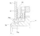
(a)図10に緩衝部材の第2実施形態を示している。この例では、第1摩擦材70は、摩擦部70aと、第1対向部70bと、第2対向部70cと、を有している。 (A) FIG. 10 shows a second embodiment of the cushioning member. In this example, the first friction material 70 has a friction portion 70a, a first facing portion 70b, and a second facing portion 70c.

摩擦部70aは第1実施形態の摩擦部61aに相当し、第1対向部70bは第1実施形態の緩衝部61bに相当している。すなわち、摩擦部70aは、円板状に形成され、クラッチプレート24の側面に当接可能である。第1対向部70bは、摩擦部70aの内周端からリティニングプレート25側に軸方向に延び、第1摩擦ワッシャ51の外周面に対して、径方向に所定の隙間をあけて対向する位置に配置されている。また、第2対向部70cは、第1対向部70bの先端から径方向内方に延び、第1摩擦ワッシャ51の側面と所定の隙間をあけて対向して配置されている。 The friction portion 70a corresponds to the friction portion 61a of the first embodiment, and the first facing portion 70b corresponds to the cushioning portion 61b of the first embodiment. That is, the friction portion 70a is formed in a disk shape and can come into contact with the side surface of the clutch plate 24. The first facing portion 70b extends axially from the inner peripheral end of the friction portion 70a toward the reinforcement plate 25, and faces the outer peripheral surface of the first friction washer 51 with a predetermined gap in the radial direction. Is located in. Further, the second facing portion 70c extends inward in the radial direction from the tip of the first facing portion 70b, and is arranged so as to face the side surface of the first friction washer 51 with a predetermined gap.

このような実施形態では、第1対向部70b及び第2対向部70cによって、第1摩擦ワッシャ51の姿勢変動をより抑えることが可能になる。 In such an embodiment, the first facing portion 70b and the second facing portion 70c make it possible to further suppress the posture fluctuation of the first friction washer 51.

(b)図11に緩衝部材の第3実施形態を示している。この例では、第1摩擦材72は、摩擦部72a及び緩衝部72bを有している。摩擦部72aは前記実施形態における摩擦部61aと同様である。緩衝部72bは、摩擦部72aの内周端から、径方向内方に、かつリティニングプレート25側に向かって傾斜している。 (B) FIG. 11 shows a third embodiment of the cushioning member. In this example, the first friction material 72 has a friction portion 72a and a cushioning portion 72b. The friction portion 72a is the same as the friction portion 61a in the embodiment. The cushioning portion 72b is inclined inward in the radial direction and toward the leaning plate 25 side from the inner peripheral end of the friction portion 72a.

一方、この例では、第1摩擦ワッシャ74は、外周面の両方の角部に傾斜面を有している。すなわち、第1摩擦ワッシャ74の外周面には、クラッチプレート24側の角部と、リティニングプレート25側の角部の両方に、中央部から側方に向かって径が小さくなる第1傾斜面74a及び第2傾斜面74bを有している。そして、第1傾斜面74aはクラッチプレート24の内周端面に接触し、第2傾斜面74bは緩衝部72bに所定の隙間を介して対向している。 On the other hand, in this example, the first friction washer 74 has inclined surfaces at both corners of the outer peripheral surface. That is, on the outer peripheral surface of the first friction washer 74, both the corner portion on the clutch plate 24 side and the corner portion on the reinforcement plate 25 side have a first inclined surface whose diameter decreases from the central portion toward the side. It has a 74a and a second inclined surface 74b. The first inclined surface 74a is in contact with the inner peripheral end surface of the clutch plate 24, and the second inclined surface 74b faces the cushioning portion 72b via a predetermined gap.

このような実施形態によっても、前記各実施形態と同様の作用効果を得ることができる。 Even with such an embodiment, the same effect as that of each of the above-described embodiments can be obtained.

(c)図12に第4実施形態を示している。この第4実施形態は、クラッチプレート及び第1摩擦ワッシャの構成が異なっている。ここでは、クラッチプレート76の内周端面76aは、径方向の斜め外方に凹む球面に一部である。また、第1摩擦ワッシャ78の外周面の角部、すなわちクラッチプレート76の内周端面76aに接触する摩擦面78aは、径方向外方に膨らむ球面の一部である。 (C) FIG. 12 shows a fourth embodiment. In this fourth embodiment, the configurations of the clutch plate and the first friction washer are different. Here, the inner peripheral end surface 76a of the clutch plate 76 is a part of a spherical surface that is recessed diagonally outward in the radial direction. Further, the corner portion of the outer peripheral surface of the first friction washer 78, that is, the friction surface 78a in contact with the inner peripheral end surface 76a of the clutch plate 76 is a part of a spherical surface that swells outward in the radial direction.

このように、クラッチプレート76の内周端面76aと第1摩擦ワッシャ78の外周面の一部である摩擦面78aとを球面の一部とし、それらを摩擦接触させることにより、スプラインハブ4に対するクラッチプレート76を含む構成部分のミスアライメントをより小さくすることができる。 In this way, the inner peripheral end surface 76a of the clutch plate 76 and the friction surface 78a which is a part of the outer peripheral surface of the first friction washer 78 are made a part of the spherical surface, and they are brought into frictional contact with each other to form a clutch for the spline hub 4. Misalignment of the components including the plate 76 can be made smaller.

(d)前記実施形態では、4段の捩り特性を有するクラッチディスク組立体に本発明を適用したが、捩じり特性の段数は限定されない。ダンパ装置を有するすべての動力伝達装置に本発明を同様に適用することができる。 (D) In the above embodiment, the present invention is applied to a clutch disc assembly having four stages of twisting characteristics, but the number of stages of twisting characteristics is not limited. The present invention can be similarly applied to all power transmission devices having a damper device.

(e)各ヒステリシストルク発生機構で発生するヒステリシストルクの大きさは限定されない。求められる捩じり特性に応じてヒステリシストルクの大きさを適宜変更が可能である。 (E) The magnitude of the hysteresis torque generated by each hysteresis torque generation mechanism is not limited. The magnitude of the hysteresis torque can be appropriately changed according to the required torsional characteristics.

(f)上記の各実施形態を、各々組み合わせて採用することができる。 (F) Each of the above embodiments can be adopted in combination.

1 クラッチディスク組立体
2 クラッチディスク
3 ダンパ機構
4 スプラインハブ
12 高剛性ダンパ
13 全領域(L-H:第2)ヒステリシストルク発生機構
16 高捩り角度領域(H:第1)ヒステリシストルク発生機構
21 ハブフランジ
24,76 クラッチプレート
25 リティニングプレート
34 サブプレート
34c 第1係合突起
51,74,78 第1摩擦ワッシャ
61,70,72 第1摩擦材
61b 緩衝部
70b 第1対向部
70c 第2対向部
1 Clutch disc assembly 2 Clutch disc 3 Damper mechanism 4 Spline hub 12 High-rigidity damper 13 All areas (LH: 2nd) Hysteresis torque generation mechanism 16 High torsion angle region (H: 1st) Hysteresis torque generation mechanism 21 Hub Flange 24,76 Clutch plate 25 Linting plate 34 Sub-plate 34c First engagement protrusion 51,74,78 First friction washer 61,70,72 First friction material 61b Buffer 70b First facing part 70c Second facing part

Claims (11)

駆動源からのトルクをトランスミッション側に伝達するとともに、トルク変動を減衰するダンパ装置であって、
環状の第1プレートを有する第1回転部材と、
前記トランスミッション側の部材に連結可能なハブと、前記ハブから径方向外方に延び前記第1プレートと軸方向に対向するフランジと、を有し、前記第1回転部材と相対回転可能な第2回転部材と、
前記第1回転部材と前記第2回転部材とを回転方向に弾性的に連結する複数の弾性部材と、
前記弾性部材の径方向内方において前記第1プレートと前記フランジとの軸方向間に配置され、前記第1プレートと前記フランジとの相対回転時に第1ヒステリシストルクを発生する第1ヒステリシストルク発生機構と、
前記ハブの外周面に設けられ前記第1プレートの内周面と摩擦接触する環状の第1摩擦部材を有し、前記第1回転部材と前記第2回転部材との相対回転時に第2ヒステリシストルクを発生させる第2ヒステリシストルク発生機構と、
前記第1ヒステリシストルク発生機構に設けられ、前記第1摩擦部材の外周面と所定の隙間をあけて配置された緩衝部材と、
を備えたダンパ装置。
It is a damper device that transmits torque from the drive source to the transmission side and attenuates torque fluctuations.
A first rotating member having an annular first plate and
A second that has a hub that can be connected to the transmission-side member and a flange that extends radially outward from the hub and faces the first plate in the axial direction, and is rotatable relative to the first rotating member. Rotating member and
A plurality of elastic members that elastically connect the first rotating member and the second rotating member in the rotational direction, and
A first hysteresis torque generation mechanism that is arranged in the radial direction of the elastic member between the first plate and the flange in the axial direction and generates a first hysteresis torque when the first plate and the flange rotate relative to each other. When,
It has an annular first friction member provided on the outer peripheral surface of the hub and in frictional contact with the inner peripheral surface of the first plate, and has a second hysteresis torque during relative rotation between the first rotating member and the second rotating member. The second hysteresis torque generation mechanism that generates
A cushioning member provided in the first hysteresis torque generation mechanism and arranged with a predetermined gap from the outer peripheral surface of the first friction member.
A damper device equipped with.
前記第1ヒステリシストルク発生機構は、前記第1プレートに摩擦接触する環状の摩擦プレートを有し、
前記緩衝部材は、前記摩擦プレートの内周面に設けられている、
請求項1に記載のダンパ装置。
The first hysteresis torque generation mechanism has an annular friction plate that is in frictional contact with the first plate.
The cushioning member is provided on the inner peripheral surface of the friction plate.
The damper device according to claim 1.
前記緩衝部材は、軸方向に延び前記第1摩擦部材の外周面と対向する第1対向部を有している、請求項1又は2に記載のダンパ装置。 The damper device according to claim 1 or 2, wherein the cushioning member has a first facing portion extending in the axial direction and facing the outer peripheral surface of the first friction member. 前記緩衝部材は、径方向に延び前記第1摩擦部材の側面と対向する第2対向部を有している、請求項3に記載のダンパ装置。 The damper device according to claim 3, wherein the cushioning member has a second facing portion that extends radially and faces the side surface of the first friction member. 前記緩衝部材は、前記第1ヒステリシストルク発生機構を構成する部材よりも高い輻射率を有する、請求項1から3のいずれかに記載のダンパ装置。 The damper device according to any one of claims 1 to 3, wherein the cushioning member has a higher emissivity than the member constituting the first hysteresis torque generation mechanism. 前記摩擦プレートは、前記フランジに係合する係合部を有し、前記フランジと相対回転不能である、請求項2に記載のダンパ装置。 The damper device according to claim 2, wherein the friction plate has an engaging portion that engages with the flange and cannot rotate relative to the flange. 前記緩衝部材は、前記第1摩擦部材より低い弾性を有する、請求項1から6のいずれかに記載のダンパ装置。 The damper device according to any one of claims 1 to 6, wherein the cushioning member has lower elasticity than the first friction member. 前記緩衝部材は、前記第1摩擦部材よりも大きい摩擦係数を有する、請求項1から7のいずれかに記載のダンパ装置。 The damper device according to any one of claims 1 to 7, wherein the cushioning member has a friction coefficient larger than that of the first friction member . 前記第1摩擦部材の前記第1プレートの内周面に接触する摩擦面は、前記第1回転部材及び第2回転部材の回転軸線に対して傾斜する傾斜面である、請求項1から8のいずれかに記載のダンパ装置。 The friction surface of the first friction member in contact with the inner peripheral surface of the first plate is an inclined surface inclined with respect to the rotation axes of the first rotating member and the second rotating member, according to claims 1 to 8. The damper device described in either. 前記第1摩擦部材の前記第1プレートの内周面に接触する摩擦面は、径方向外方に膨らむ球面の一部である、請求項1から8のいずれかに記載のダンパ装置。 The damper device according to any one of claims 1 to 8, wherein the friction surface of the first friction member in contact with the inner peripheral surface of the first plate is a part of a spherical surface that swells outward in the radial direction. 前記第1回転部材は、前記第2回転部材のフランジを挟んで前記第1プレートと軸方向において対向する第2プレートを有し、
前記第2ヒステリシストルク発生機構は、
前記フランジと前記第2プレートとの軸方向間に配置され、前記フランジの側面に摩擦接触する側面を有する環状の第2摩擦部材と、
前記第2摩擦部材を前記フランジ側に付勢する付勢部材と、
を有する、
請求項2に記載のダンパ装置。
The first rotating member has a second plate that faces the first plate in the axial direction with the flange of the second rotating member interposed therebetween.
The second hysteresis torque generation mechanism is
An annular second friction member arranged between the flange and the second plate in the axial direction and having a side surface in frictional contact with the side surface of the flange.
An urging member that urges the second friction member to the flange side, and
Have,
The damper device according to claim 2.
JP2018128751A 2018-07-06 2018-07-06 Damper device Active JP7053390B2 (en)

Priority Applications (1)

Application Number Priority Date Filing Date Title
JP2018128751A JP7053390B2 (en) 2018-07-06 2018-07-06 Damper device

Applications Claiming Priority (1)

Application Number Priority Date Filing Date Title
JP2018128751A JP7053390B2 (en) 2018-07-06 2018-07-06 Damper device

Publications (3)

Publication Number Publication Date
JP2020008061A JP2020008061A (en) 2020-01-16
JP2020008061A5 JP2020008061A5 (en) 2021-08-12
JP7053390B2 true JP7053390B2 (en) 2022-04-12

Family

ID=69151215

Family Applications (1)

Application Number Title Priority Date Filing Date
JP2018128751A Active JP7053390B2 (en) 2018-07-06 2018-07-06 Damper device

Country Status (1)

Country Link
JP (1) JP7053390B2 (en)

Families Citing this family (1)

* Cited by examiner, † Cited by third party
Publication number Priority date Publication date Assignee Title
CN114992280B (en) * 2022-05-09 2024-05-07 浙江吉利控股集团有限公司 Transmission device, dual-mass flywheel and clutch transmission structure and vehicle

Citations (3)

* Cited by examiner, † Cited by third party
Publication number Priority date Publication date Assignee Title
JP2000170790A (en) 1998-12-08 2000-06-20 Exedy Corp Friction mechanism, damper disk assembly and clutch disk
JP2009019746A (en) 2007-07-13 2009-01-29 Exedy Corp Damper mechanism
JP2015175440A (en) 2014-03-14 2015-10-05 株式会社エクセディ Damper disc assembly

Family Cites Families (1)

* Cited by examiner, † Cited by third party
Publication number Priority date Publication date Assignee Title
JPH0649940Y2 (en) * 1989-05-16 1994-12-14 三菱自動車工業株式会社 Clutch device

Patent Citations (3)

* Cited by examiner, † Cited by third party
Publication number Priority date Publication date Assignee Title
JP2000170790A (en) 1998-12-08 2000-06-20 Exedy Corp Friction mechanism, damper disk assembly and clutch disk
JP2009019746A (en) 2007-07-13 2009-01-29 Exedy Corp Damper mechanism
JP2015175440A (en) 2014-03-14 2015-10-05 株式会社エクセディ Damper disc assembly

Also Published As

Publication number Publication date
JP2020008061A (en) 2020-01-16

Similar Documents

Publication Publication Date Title
JP2008089089A (en) Damper mechanism
JP7181737B2 (en) Torque converter lockup device
US8454446B2 (en) Damper mechanism
JP4495936B2 (en) Clutch disc assembly
JP7053390B2 (en) Damper device
JP2009019746A (en) Damper mechanism
JP4445529B2 (en) Damper mechanism
JP7299828B2 (en) damper device
JP7040974B2 (en) Damper device
JP7040962B2 (en) Damper device
JP7012564B2 (en) Damper device
JP7148419B2 (en) damper device
JP6976874B2 (en) Power transmission structure and power transmission device
JP2022052126A (en) Hysteresis torque generating mechanism and power transmission device
JP7384654B2 (en) damper device
JP7376334B2 (en) damper device
JP3986266B2 (en) Clutch disc assembly
JP2019132288A (en) Power transmission device
JP6545972B2 (en) Damper disc assembly
CN209818581U (en) Pin for caulking and power transmission structure
JP6782349B2 (en) Damper disc assembly
JP7306890B2 (en) damper device
JP5060269B2 (en) Torsional vibration reduction device
WO2005028915A1 (en) Flexible flywheel
JP2022184493A (en) damper device

Legal Events

Date Code Title Description
A521 Request for written amendment filed

Free format text: JAPANESE INTERMEDIATE CODE: A523

Effective date: 20210621

A621 Written request for application examination

Free format text: JAPANESE INTERMEDIATE CODE: A621

Effective date: 20210621

A977 Report on retrieval

Free format text: JAPANESE INTERMEDIATE CODE: A971007

Effective date: 20220311

TRDD Decision of grant or rejection written
A01 Written decision to grant a patent or to grant a registration (utility model)

Free format text: JAPANESE INTERMEDIATE CODE: A01

Effective date: 20220329

A61 First payment of annual fees (during grant procedure)

Free format text: JAPANESE INTERMEDIATE CODE: A61

Effective date: 20220331

R150 Certificate of patent or registration of utility model

Ref document number: 7053390

Country of ref document: JP

Free format text: JAPANESE INTERMEDIATE CODE: R150