JP7040962B2 - Damper device - Google Patents

Damper device Download PDF

Info

Publication number
JP7040962B2
JP7040962B2 JP2018040562A JP2018040562A JP7040962B2 JP 7040962 B2 JP7040962 B2 JP 7040962B2 JP 2018040562 A JP2018040562 A JP 2018040562A JP 2018040562 A JP2018040562 A JP 2018040562A JP 7040962 B2 JP7040962 B2 JP 7040962B2
Authority
JP
Japan
Prior art keywords
plate
rotating member
urging
hysteresis torque
groove
Prior art date
Legal status (The legal status is an assumption and is not a legal conclusion. Google has not performed a legal analysis and makes no representation as to the accuracy of the status listed.)
Active
Application number
JP2018040562A
Other languages
Japanese (ja)
Other versions
JP2019157875A (en
JP2019157875A5 (en
Inventor
秀幸 今中
Current Assignee (The listed assignees may be inaccurate. Google has not performed a legal analysis and makes no representation or warranty as to the accuracy of the list.)
Exedy Corp
Original Assignee
Exedy Corp
Priority date (The priority date is an assumption and is not a legal conclusion. Google has not performed a legal analysis and makes no representation as to the accuracy of the date listed.)
Filing date
Publication date
Application filed by Exedy Corp filed Critical Exedy Corp
Priority to JP2018040562A priority Critical patent/JP7040962B2/en
Priority to CN201920083929.3U priority patent/CN209539918U/en
Publication of JP2019157875A publication Critical patent/JP2019157875A/en
Publication of JP2019157875A5 publication Critical patent/JP2019157875A5/ja
Application granted granted Critical
Publication of JP7040962B2 publication Critical patent/JP7040962B2/en
Active legal-status Critical Current
Anticipated expiration legal-status Critical

Links

Images

Description

本発明は、ダンパ装置、特に、入力されたトルクを出力側に伝達するとともに、トルク変動を減衰するダンパ装置に関する。 The present invention relates to a damper device, particularly a damper device that transmits an input torque to an output side and attenuates torque fluctuations.

車輌におけるアイドリング時及び走行時には、例えばエンジンから伝達されるトルク変動に起因する振動及び異音が発生する場合がある。この問題を解決するために、特許文献1に示されるようなダンパが設けられている。このダンパは、4段の捩り特性を有するとともに、低捩り角度領域から高捩り角度領域の全領域にわたってヒステリシストルクを発生する機構と、低捩り角度領域の一部でヒステリシストルクを発生する機構と、高捩り角度領域においてのみヒステリシストルクを発生する機構と、が設けられている。 When the vehicle is idling and running, vibration and abnormal noise due to torque fluctuations transmitted from the engine, for example, may occur. In order to solve this problem, a damper as shown in Patent Document 1 is provided. This damper has four stages of torsional characteristics, and has a mechanism that generates hysteresis torque over the entire region from the low torsional angle region to the high torsional angle region, and a mechanism that generates hysteresis torque in a part of the low torsional angle region. A mechanism for generating a hysteresis torque only in a high torsional angle region is provided.

特開2009-19746号公報Japanese Unexamined Patent Publication No. 2009-19746

特許文献1の装置では、低捩り角度領域の一部でヒステリシストルクを得るために、ウェーブスプリングが用いられている。この角度領域で、より大きなヒステリシストルクが必要な場合は、付勢力の大きなウェーブスプリングを用いるか、別のウェーブスプリングを配置する必要がある。このため、大きなヒステリシストルクが必要な場合は、広い軸方向スペースが必要となり、装置の軸方向寸法の小型化の妨げになっている。 In the apparatus of Patent Document 1, a wave spring is used in order to obtain a hysteresis torque in a part of a low torsional angle region. If a larger hysteresis torque is required in this angular region, it is necessary to use a wave spring with a large urging force or to arrange another wave spring. Therefore, when a large hysteresis torque is required, a wide axial space is required, which hinders the miniaturization of the axial dimension of the device.

本発明の課題は、ヒステリシストルク発生機構の軸方向寸法を抑えることにある。 An object of the present invention is to suppress the axial dimension of the hysteresis torque generation mechanism.

(1)本発明に係るダンパ装置は、入力されたトルクを出力側に伝達するとともに、トルク変動を減衰する装置である。このダンパ装置は、第1回転部材と、第2回転部材と、複数の弾性部材と、ヒステリシストルク発生機構と、を備えている。第2回転部材は、第1回転部材に対して相対回転自在に配置されている。弾性部材は、第1回転部材と第2回転部材とを回転方向に弾性的に連結する。ヒステリシストルク発生機構は、第1回転部材と第2回転部材との相対回転時にヒステリシストルクを発生する。 (1) The damper device according to the present invention is a device that transmits the input torque to the output side and attenuates the torque fluctuation. This damper device includes a first rotating member, a second rotating member, a plurality of elastic members, and a hysteresis torque generating mechanism. The second rotating member is arranged so as to be rotatable relative to the first rotating member. The elastic member elastically connects the first rotating member and the second rotating member in the rotational direction. The hysteresis torque generation mechanism generates a hysteresis torque when the first rotating member and the second rotating member rotate relative to each other.

また、ヒステリシストルク発生機構は、溝と、付勢部材と、を有している。溝は、第1回転部材の第2回転部材に対向する側面に形成されている。付勢部材は、溝に装着されており、座面部と、付勢部と、を有している。座面部は、溝の底面の少なくとも一部に接触する面を有する。付勢部は、座面部の第2回転部材側に設けられ第1回転部材と第2回転部材とを互いに圧接する。 Further, the hysteresis torque generation mechanism has a groove and an urging member. The groove is formed on the side surface of the first rotating member facing the second rotating member. The urging member is mounted in the groove and has a seat surface portion and an urging portion. The seating surface has a surface that contacts at least a part of the bottom surface of the groove. The urging portion is provided on the second rotating member side of the seat surface portion, and the first rotating member and the second rotating member are pressed against each other.

この装置では、相対回転する第1回転部材と第2回転部材とが、付勢部材によって互いに圧接され、これによりヒステリシストルクが発生する。 In this device, the first rotating member and the second rotating member that rotate relative to each other are pressed against each other by the urging member, whereby a hysteresis torque is generated.

ここで、付勢部材は、第1回転部材に形成された溝に装着されているので、付勢部材を配置するための軸方向寸法を抑えることができる。このため、装置全体の軸方向寸法の小型化が可能になる。 Here, since the urging member is mounted in the groove formed in the first rotating member, the axial dimension for arranging the urging member can be suppressed. Therefore, it is possible to reduce the axial dimension of the entire device.

また、付勢部材は、その座面部が溝の底面に面接触する。このため、付勢部材と溝底面との間の面圧を抑えることができ、付勢部材の摩耗を抑えて、長期にわたって安定したヒステリシストルクを得ることができる。また、摩耗を抑えることができるので、高いヒステリシストルクを設定することができる。 Further, the seat surface portion of the urging member comes into surface contact with the bottom surface of the groove. Therefore, the surface pressure between the urging member and the bottom surface of the groove can be suppressed, the wear of the urging member can be suppressed, and a stable hysteresis torque can be obtained for a long period of time. Further, since wear can be suppressed, a high hysteresis torque can be set.

(2)好ましくは、付勢部材の座面部は、溝内に移動可能に装着されており、溝の底面に対して摺接する。 (2) Preferably, the seat surface portion of the urging member is movably mounted in the groove and is in sliding contact with the bottom surface of the groove.

ここでは、第1回転部材と第2回転部材との間で発生するヒステリシストルクに加えて、付勢部材と溝との間でもヒステリシストルクが発生する。このため、各部において小さい摩擦力で所望のヒステリシストルクを得ることができ、各部材の摩耗を抑えることができる。 Here, in addition to the hysteresis torque generated between the first rotating member and the second rotating member, a hysteresis torque is also generated between the urging member and the groove. Therefore, a desired hysteresis torque can be obtained with a small frictional force in each portion, and wear of each member can be suppressed.

(3)好ましくは、ヒステリシストルク発生機構の溝は環状に形成されている。ここでは、付勢部材が溝内で回転しやすくなり(すなわち、付勢部材と溝との間で摺接しやすくなり)、所望のヒステリシストルクを得ることができる。 (3) Preferably, the groove of the hysteresis torque generation mechanism is formed in an annular shape. Here, the urging member is more likely to rotate in the groove (that is, is more likely to be in sliding contact between the urging member and the groove), and a desired hysteresis torque can be obtained.

(4)好ましくは、座面部は、一部に欠落部を有する環状でかつ平坦な形状である。また、付勢部は、座面部に連続して環状に形成され、円周方向に所定の間隔で軸方向に突出し弾性変形可能な複数の押圧部を有する。 (4) The seat surface portion preferably has an annular and flat shape having a partially missing portion. Further, the urging portion is continuously formed in an annular shape on the seat surface portion, and has a plurality of pressing portions that protrude in the axial direction at predetermined intervals in the circumferential direction and are elastically deformable.

ここでは、座面部と付勢部とが連続して形成されているので、付勢部材の製造が容易になる。また、座面部と付勢部との間での相対回転が存在しないので、座面部と付勢部との間の摩耗がなくなる。 Here, since the seat surface portion and the urging portion are continuously formed, the urging member can be easily manufactured. Further, since there is no relative rotation between the seat surface portion and the urging portion, there is no wear between the seat surface portion and the urging portion.

(5)好ましくは、付勢部材は、座面部及び付勢部が連続する線材で形成されている。 (5) Preferably, the urging member is formed of a wire rod having a seat surface portion and a urging portion continuous.

(6)好ましくは、座面部は、溝の底面に接触するように配置された環状のワッシャである。また、付勢部は、ワッシャの表面に配置され、円周方向に所定の間隔で軸方向に突出し弾性変形可能な複数の押圧部を有する。 (6) Preferably, the seat surface portion is an annular washer arranged so as to come into contact with the bottom surface of the groove. Further, the urging portion is arranged on the surface of the washer, and has a plurality of pressing portions that protrude in the axial direction at predetermined intervals in the circumferential direction and can be elastically deformed.

ここでは、座面部と付勢部とが別部材で形成されている。このため、溝底面と座面部との間の摩擦抵抗、及び付勢部の剛性を、それぞれ別に任意に調整することができる。 Here, the seat surface portion and the urging portion are formed of separate members. Therefore, the frictional resistance between the groove bottom surface and the seat surface portion and the rigidity of the urging portion can be arbitrarily adjusted separately.

(7)好ましくは、第1回転部材は、軸方向に対向して配置された第1入力プレート及び第2入力プレートを有している。また、第2回転部材は、1対のプレート部材の軸方向間に配置された出力プレートを有している。 (7) Preferably, the first rotating member has a first input plate and a second input plate arranged so as to face each other in the axial direction. Further, the second rotating member has an output plate arranged between a pair of plate members in the axial direction.

(8)好ましくは、ヒステリシストルク発生機構の溝は、第1入力プレートに形成されている。また、付勢部材は、出力プレートを第2入力プレートに押圧する。 (8) Preferably, the groove of the hysteresis torque generation mechanism is formed in the first input plate. Further, the urging member presses the output plate against the second input plate.

以上のような本発明では、ヒステリシストルク発生機構の軸方向寸法を抑えることができ、装置の小型化が実現可能となる。また、付勢部材の摩耗を抑えることができるので、長期にわたって安定したヒステリシストルクを得ることができ、さらに、高いヒステリシストルクを設定することができる。 In the present invention as described above, the axial dimension of the hysteresis torque generation mechanism can be suppressed, and the device can be downsized. Further, since the wear of the urging member can be suppressed, a stable hysteresis torque can be obtained for a long period of time, and a high hysteresis torque can be set.

本発明の一実施形態としてのクラッチディスク組立体の縦断面概略図。Schematic diagram of a vertical cross section of a clutch disc assembly as an embodiment of the present invention. クラッチディスク組立体の正面部分図。Front partial view of the clutch disc assembly. クラッチディスク組立体の捩り特性線図。Twist characteristic diagram of the clutch disc assembly. 図1の拡大部分図。Enlarged partial view of FIG. 図2の拡大部分図。Enlarged partial view of FIG. ストップピンの正面図及び底面図。Front view and bottom view of the stop pin. ストップピンの取付構造を示す平面図。The plan view which shows the mounting structure of a stop pin. 図1の拡大部分図。Enlarged partial view of FIG. 主に低剛性ダンパの分解斜視図。An exploded perspective view of a low-rigidity damper. 付勢部材の外観図。External view of the urging member. 図9の一部を示す図。The figure which shows a part of FIG. 付勢部材の他の実施形態を示す外観図。The external view which shows the other embodiment of the urging member.

図1は、本発明に一実施形態によるダンパ装置を有するクラッチディスク組立体の断面図である。図1のO-O線は、クラッチディスク組立体1の回転軸線である。このクラッチディスク組立体1は、図1の左側に配置されるエンジン及びフライホイールからのトルクを、図1の右側に配置されるトランスミッションに伝達し、かつトルク変動を減衰する。また、図2はクラッチディスク組立体1の正面部分図である。 FIG. 1 is a cross-sectional view of a clutch disc assembly having a damper device according to an embodiment of the present invention. The OO line in FIG. 1 is the rotation axis of the clutch disc assembly 1. The clutch disc assembly 1 transmits torque from the engine and flywheel located on the left side of FIG. 1 to a transmission arranged on the right side of FIG. 1 and attenuates torque fluctuations. Further, FIG. 2 is a front partial view of the clutch disc assembly 1.

[全体構成]
クラッチディスク組立体1は、摩擦係合によりフライホイールからトルクが入力されるクラッチディスク2と、クラッチディスク2から入力されるトルク変動を減衰及び吸収するダンパ機構3と、スプラインハブ4と、を有している。
[overall structure]
The clutch disc assembly 1 includes a clutch disc 2 to which torque is input from a flywheel by frictional engagement, a damper mechanism 3 to attenuate and absorb torque fluctuations input from the clutch disc 2, and a spline hub 4. is doing.

[クラッチディスク2]
クラッチディスク2は、図示しないプレッシャプレートによってフライホイールに押し付けられる。クラッチディスク2は、クッショニングプレート6と、クッショニングプレート6の両面にリベット7によって固定される1対の摩擦フェーシング8と、を有している。クッショニングプレート6はダンパ機構3の外周部に固定されている。
[Clutch disc 2]
The clutch disc 2 is pressed against the flywheel by a pressure plate (not shown). The clutch disc 2 has a cushioning plate 6 and a pair of friction facings 8 fixed to both sides of the cushioning plate 6 by rivets 7. The cushioning plate 6 is fixed to the outer peripheral portion of the damper mechanism 3.

[ダンパ機構3]
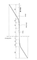
ダンパ機構3は、エンジンから伝達されるトルク変動を効果的に減衰及び吸収するために、図3に示すように、正側(駆動側の回転方向)及び負側において4段の捩り特性を有している。具体的には、捩り特性の正側及び負側において、1段目(L1)領域及び2段目(L2)領域は低捩り剛性及び低ヒステリシストルクの領域であり、3段目(H3)領域及び4段目(H4)領域は高捩り剛性及び高ヒステリシストルクの領域である。
[Damper mechanism 3]
As shown in FIG. 3, the damper mechanism 3 has four stages of torsional characteristics on the positive side (rotational direction on the drive side) and the negative side in order to effectively attenuate and absorb torque fluctuations transmitted from the engine. is doing. Specifically, on the positive and negative sides of the torsional characteristics, the first stage (L1) region and the second stage (L2) region are regions of low torsional rigidity and low hysteresis torque, and the third stage (H3) region. The fourth stage (H4) region is a region of high torsional rigidity and high hysteresis torque.

ダンパ機構3は、低剛性ダンパ11と、高剛性ダンパ12と、全領域ヒステリシストルク発生機構(以下、「L-Hヒス発生機構」と記す)13と、低捩り角度領域ヒステリシストルク発生機構(以下、「Lヒス発生機構」と記す)14と、中捩り角度領域ヒステリシストルク発生機構(以下、「L2ヒス発生機構」と記す)15と、高捩り角度領域ヒステリシストルク発生機構(以下、「Hヒス発生機構」と記す)16と、ストッパ機構17と、を有している。 The damper mechanism 3 includes a low-rigidity damper 11, a high-rigidity damper 12, an all-region hysteresis torque generation mechanism (hereinafter referred to as “LH hiss generation mechanism”) 13, and a low torsion angle region hysteresis torque generation mechanism (hereinafter referred to as “LH hiss generation mechanism”) 13. , "L hiss generation mechanism") 14, medium torsion angle region hysteresis torque generation mechanism (hereinafter referred to as "L2 hiss generation mechanism") 15, and high torsion angle region hysteresis torque generation mechanism (hereinafter, "H hiss") It has a generation mechanism) 16 and a stopper mechanism 17.

低剛性ダンパ11は、低捩り角度領域(L1+L2)で作動する。高剛性ダンパ12は、低捩り角度領域よりも捩り角度の大きい高捩り角度領域(H3+H4)で作動する。また、高剛性ダンパ12は低剛性ダンパ11よりも高い捩り剛性を有する。 The low-rigidity damper 11 operates in a low torsional angle region (L1 + L2). The high-rigidity damper 12 operates in a high torsional angle region (H3 + H4) in which the torsional angle is larger than the low torsional angle region. Further, the high-rigidity damper 12 has a higher torsional rigidity than the low-rigidity damper 11.

L-Hヒス発生機構13は、低捩り角度領域(L1+L2)及び高捩り角度領域(H3+H4)の全捩り角度領域においてヒステリシストルクを発生する機構である。Lヒス発生機構14は、低捩り角度領域の全領域(L1+L2)でのみヒステリシストルクを発生する機構である。L2ヒス発生機構15は、2段目の第2捩り角度領域(L2)でのみヒステリシストルクを発生する機構である。Hヒス発生機構16は、高捩り角度領域(H3+H4)でのみヒステリシストルクを発生する機構である。 The LH hiss generation mechanism 13 is a mechanism that generates a hysteresis torque in the entire torsion angle region of the low torsion angle region (L1 + L2) and the high torsion angle region (H3 + H4). The L hiss generation mechanism 14 is a mechanism that generates a hysteresis torque only in the entire region (L1 + L2) of the low twist angle region. The L2 hiss generation mechanism 15 is a mechanism that generates a hysteresis torque only in the second twist angle region (L2) of the second stage. The H hiss generation mechanism 16 is a mechanism that generates a hysteresis torque only in a high torsional angle region (H3 + H4).

ストッパ機構17は、入力側の部材であるクラッチディスク2と、出力側の部材であるスプラインハブ4と、の捩り角度(相対回転角度)が所定の角度になると、それ以上の両部材の相対回転角度を禁止する機構である。 When the twist angle (relative rotation angle) of the clutch disc 2 which is a member on the input side and the spline hub 4 which is a member on the output side becomes a predetermined angle, the stopper mechanism 17 further rotates the relative rotation of both members. It is a mechanism that prohibits angles.

<高剛性ダンパ12>
高剛性ダンパ12は、図4に示すように、入力側回転部材20と、ハブフランジ21と、複数の高剛性スプリング22と、を有している。
<High rigidity damper 12>
As shown in FIG. 4, the high-rigidity damper 12 has an input-side rotating member 20, a hub flange 21, and a plurality of high-rigidity springs 22.

-入力側回転部材20-
入力側回転部材20には、クラッチディスク2を介してエンジンからトルクが入力され、クラッチプレート24及びリティニングプレート25を有している。
-Input side rotating member 20-
Torque is input from the engine to the input-side rotating member 20 via the clutch disc 2, and has a clutch plate 24 and a lotining plate 25.

クラッチプレート24及びリティニングプレート25は、実質的に環状に形成され、軸方向に間隔を隔てて配置されている。クラッチプレート24はエンジン側に配置され、リティニングプレート25はトランスミッション側に配置されている。クラッチプレート24及びリティニングプレート25は、外周部がストップピン26によって連結されており、一体で回転する。 The clutch plate 24 and the subtraction plate 25 are formed in a substantially annular shape and are arranged at intervals in the axial direction. The clutch plate 24 is arranged on the engine side, and the leaning plate 25 is arranged on the transmission side. The outer peripheral portion of the clutch plate 24 and the subtraction plate 25 are connected by a stop pin 26 and rotate integrally.

クラッチプレート24及びリティニングプレート25には、図2に示すように、それぞれ4個の第1保持部24a,25a及び第2保持部24b,25bが円周方向に間隔を隔てて形成されている。第1保持部24a,25aと第2保持部24b,25bとは円周方向に交互に配置されている。また、リティニングプレート25には、複数の係合孔25cが形成されている。 As shown in FIG. 2, four first holding portions 24a and 25a and second holding portions 24b and 25b are formed on the clutch plate 24 and the subtraction plate 25 at intervals in the circumferential direction, respectively. .. The first holding portions 24a and 25a and the second holding portions 24b and 25b are alternately arranged in the circumferential direction. Further, a plurality of engaging holes 25c are formed in the reinforcement plate 25.

なお、図2では、リティニングプレート25を示しているが、各保持部24a,24b,24b,25bに関しては、逆側に配置されたクラッチプレート24も同様の構成である。また、図2では、リティニングプレート25の一部を破断して示している。 Although the thinning plate 25 is shown in FIG. 2, the clutch plates 24 arranged on the opposite sides of the holding portions 24a, 24b, 24b, and 25b have the same configuration. Further, in FIG. 2, a part of the linting plate 25 is broken and shown.

-ハブフランジ21-
ハブフランジ21は、略円板状の部材であり(図9参照)、スプラインハブ4の外周に配置されている。ハブフランジ21は、クラッチプレート24とリティニングプレート25との軸方向間に配置され、これらの両プレート24,25と所定の角度範囲内で相対回転可能である。図5に示すように、ハブフランジ21とスプラインハブ4とは、互いの内周部及び外周部に形成された複数の歯21c,4cによって噛み合っている。なお、互いの歯21c,4cの間には所定の隙間G1が設定されている。すなわち、ハブフランジ21とスプラインハブ4とは、歯21c,4cの隙間G1の角度分(低捩り角度領域(L1+L2)に相当)だけ相対回転が可能である。
-Hub flange 21-
The hub flange 21 is a substantially disk-shaped member (see FIG. 9), and is arranged on the outer periphery of the spline hub 4. The hub flange 21 is arranged between the clutch plate 24 and the reinforcement plate 25 in the axial direction, and can rotate relative to both the plates 24 and 25 within a predetermined angle range. As shown in FIG. 5, the hub flange 21 and the spline hub 4 are meshed with each other by a plurality of teeth 21c and 4c formed on the inner peripheral portion and the outer peripheral portion of each other. A predetermined gap G1 is set between the teeth 21c and 4c. That is, the hub flange 21 and the spline hub 4 can rotate relative to each other by the angle of the gap G1 between the teeth 21c and 4c (corresponding to the low twist angle region (L1 + L2)).

ハブフランジ21には、図5に示すように、クラッチプレート24及びリティニングプレート25の第1保持部24a,25a及び第2保持部24b,25bと対向する位置に、それぞれ第1窓孔21a及び第2窓孔21bが形成されている。そして、第1窓孔21aに第1高剛性スプリング22aが収容され、この第1高剛性スプリング22aがクラッチプレート24及びリティニングプレート25の第1保持部24a,25aによって軸方向及び径方向に保持されている。また、第2窓孔21bに第2高剛性スプリング22bが収容され、この第2高剛性スプリング22bがクラッチプレート24及びリティニングプレート25の第2保持部24b,25bによって軸方向及び径方向に保持されている。 As shown in FIG. 5, the hub flange 21 has a first window hole 21a and a position facing the first holding portions 24a and 25a and the second holding portions 24b and 25b of the clutch plate 24 and the leaning plate 25, respectively. The second window hole 21b is formed. Then, the first high-rigidity spring 22a is housed in the first window hole 21a, and the first high-rigidity spring 22a is held axially and radially by the first holding portions 24a and 25a of the clutch plate 24 and the leaning plate 25. Has been done. Further, a second high-rigidity spring 22b is housed in the second window hole 21b, and the second high-rigidity spring 22b is held in the axial and radial directions by the second holding portions 24b and 25b of the clutch plate 24 and the retaining plate 25. Has been done.

なお、クラッチプレート24及びリティニングプレート25の第1保持部24a,25a及び第2保持部24b,25bの円周方向の両端は、各高剛性スプリング22a,22bの端面に係合可能である。 Both ends of the first holding portions 24a, 25a and the second holding portions 24b, 25b of the clutch plate 24 and the reinforcement plate 25 in the circumferential direction can be engaged with the end faces of the high-rigidity springs 22a, 22b.

ここで、ハブフランジ21の第1窓孔21aには第1高剛性スプリング22aが、第2窓孔21bには第2高剛性スプリング22bが、それぞれ円周方向に隙間なく配置されている。一方、クラッチプレート24及びリティニングプレート25の第1保持部24a,25aには第1高剛性スプリング22aが円周方向に隙間なく配置されているが、両プレート24,25の第2保持部24b,25bには、第2高剛性スプリング22bが円周方向に隙間G2(図2及び図5参照)を介して配置されている。この隙間G2が3段目の捩り角度分(角度領域H3)に相当している。 Here, the first high-rigidity spring 22a is arranged in the first window hole 21a of the hub flange 21, and the second high-rigidity spring 22b is arranged in the second window hole 21b without any gap in the circumferential direction. On the other hand, the first high-rigidity springs 22a are arranged on the first holding portions 24a and 25a of the clutch plate 24 and the reinforcement plate 25 without gaps in the circumferential direction, but the second holding portions 24b of both plates 24 and 25 are arranged. At 25b, a second high-rigidity spring 22b is arranged in the circumferential direction via a gap G2 (see FIGS. 2 and 5). This gap G2 corresponds to the twist angle of the third stage (angle region H3).

なお、ハブフランジ21の第2窓孔21bのそれぞれの内周側には、軸方向に貫通する係合孔21eが形成されている。 An engaging hole 21e penetrating in the axial direction is formed on the inner peripheral side of each of the second window holes 21b of the hub flange 21.

以上の構成により、詳細は後述するが、高捩り角度領域H3,H4では、まず第1高剛性スプリング22aのみが圧縮され(H3領域)、その後、第1高剛性スプリング22aに加えて第2高剛性スプリング22bが圧縮される(H4領域)ことになる。 With the above configuration, although details will be described later, in the high torsion angle regions H3 and H4, only the first high-rigidity spring 22a is first compressed (H3 region), and then the second height is added to the first high-rigidity spring 22a. The rigid spring 22b is compressed (H4 region).

<ストッパ機構17>
ストッパ機構17は、図5に示すように、ハブフランジ21の外周部に形成された複数のストッパ用切欠21dと、前述のストップピン26と、から構成されている。ストッパ用切欠21dは、所定の角度範囲にわたって形成されており、径方向外方に開いている。そして、このストッパ用切欠21dをストップピン26が軸方向に貫通している。
<Stopper mechanism 17>
As shown in FIG. 5, the stopper mechanism 17 is composed of a plurality of stopper notches 21d formed on the outer peripheral portion of the hub flange 21 and the above-mentioned stop pin 26. The stopper notch 21d is formed over a predetermined angular range and is radially outwardly open. The stop pin 26 penetrates the stopper notch 21d in the axial direction.

また、切欠21dは、円周方向の両端部が内周側に向かって深く形成され、中央部分が浅く形成されている。この浅い部分の内周側に、第2窓孔21bが形成されている。 Further, in the notch 21d, both end portions in the circumferential direction are formed deeply toward the inner peripheral side, and the central portion is formed shallowly. A second window hole 21b is formed on the inner peripheral side of this shallow portion.

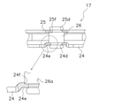
ストップピン26及びその取り付け部分を、図6及び図7に拡大して示している。なお、図6は、かしめる前のストップピン26を示しており、同図(a)は正面図、(b)は底面図である。また、図7はストップピン26がかしめられて固定された状態を径方向外方から視た平面図である。 The stop pin 26 and its mounting portion are shown enlarged in FIGS. 6 and 7. Note that FIG. 6 shows the stop pin 26 before caulking, where FIG. 6A is a front view and FIG. 6B is a bottom view. Further, FIG. 7 is a plan view of the state in which the stop pin 26 is crimped and fixed as viewed from the outside in the radial direction.

ストップピン26は、胴部26aと、胴部26aより小型で相似形の首部26bと、を有している。首部26bは胴部26aの両端に形成されている。胴部26a及び首部26bは、それぞれ大径部及び小径部を有する異形断面である。詳細には、胴部26a及び首部26bは、それぞれ断面が小判形状である。このストップピン26は、図5に示すように、小径部が径方向を、大径部が円周方向を向くように組み付けられる。 The stop pin 26 has a body portion 26a and a neck portion 26b that is smaller and has a similar shape than the body portion 26a. The neck portion 26b is formed at both ends of the body portion 26a. The body portion 26a and the neck portion 26b are irregular cross sections having a large diameter portion and a small diameter portion, respectively. Specifically, the body portion 26a and the neck portion 26b each have an oval cross section. As shown in FIG. 5, the stop pin 26 is assembled so that the small diameter portion faces the radial direction and the large diameter portion faces the circumferential direction.

図7に示すように、クラッチプレート24及びリティニングプレート25には、ストップピン26が装着される孔24d,25dが形成されている。この孔24d,25dに、ストップピン26の首部26bが挿入され、胴部26aの端面が、クラッチプレート24及びリティニングプレート25の側面に当接している。そして、首部26bの頭部をかしめることによって、クラッチプレート24とリティニングプレート25とが、軸方向に所定の隙間を介して固定される。 As shown in FIG. 7, holes 24d and 25d in which the stop pin 26 is mounted are formed in the clutch plate 24 and the reinforcement plate 25. The neck portion 26b of the stop pin 26 is inserted into the holes 24d and 25d, and the end surface of the body portion 26a is in contact with the side surfaces of the clutch plate 24 and the reinforcement plate 25. Then, by crimping the head portion of the neck portion 26b, the clutch plate 24 and the leaning plate 25 are fixed via a predetermined gap in the axial direction.

クラッチプレート24において、孔24dの周囲には、コイニング加工によってリティニングプレート25側に凹む凹部24eが形成されている。この凹部24eのリティニングプレート25側の面には、ストップピン26の胴部26aの端部外周面を受ける受け部24fが形成されている。受け部24fの形状は、胴部26aの形状と同様であり、胴部26aは受け部24fに隙間なく嵌合している。このような構成により、クラッチプレート24とストップピン26とは、受け部24fと胴部26aとの接触によってトルクの伝達が可能になっている。 In the clutch plate 24, a recess 24e recessed on the tinting plate 25 side is formed around the hole 24d by a coining process. A receiving portion 24f for receiving the outer peripheral surface of the end portion of the body portion 26a of the stop pin 26 is formed on the surface of the recess 24e on the side of the lining plate 25. The shape of the receiving portion 24f is the same as the shape of the body portion 26a, and the body portion 26a is fitted to the receiving portion 24f without a gap. With such a configuration, the clutch plate 24 and the stop pin 26 can transmit torque by contact between the receiving portion 24f and the body portion 26a.

なお、リティニングプレート25においては、クラッチプレート24の凹部24eに相当する部分は形成されていないが、クラッチプレート24の受け部24fと同様の受け部25fが形成されている。 In the subtraction plate 25, a portion corresponding to the recess 24e of the clutch plate 24 is not formed, but a receiving portion 25f similar to the receiving portion 24f of the clutch plate 24 is formed.

このようなストッパ機構17では、以下のような特徴を有している。 Such a stopper mechanism 17 has the following features.

(1)ストップピン26を異形断面にし、小径部分が径方向を向くように装着しているので、従来に比較してストッパ機構17の径方向スペースを小さくできる。このため、ストッパ機構17を比較的外周側に配置でき、高剛性スプリング22を配置するための円周方向スペースを従来に比較して長く確保できる。したがって、捩り角度の広角化を実現できる。 (1) Since the stop pin 26 has a modified cross section and is mounted so that the small diameter portion faces in the radial direction, the radial space of the stopper mechanism 17 can be reduced as compared with the conventional case. Therefore, the stopper mechanism 17 can be arranged on the outer peripheral side relatively, and a space in the circumferential direction for arranging the high-rigidity spring 22 can be secured longer than in the conventional case. Therefore, it is possible to realize a wide twist angle.

(2)ストップピン26は、異形断面にもかかわらず、胴部26aの全周に座(プレート側面に当接する部分)が存在するので、ストップピン26をかしめた際の充填率が損なわれることはない。 (2) The stop pin 26 has a seat (a portion that abuts on the side surface of the plate) on the entire circumference of the body portion 26a despite the irregular cross section, so that the filling rate when the stop pin 26 is crimped is impaired. There is no.

(3)ストップピン26に伝達されるトルクを、首部26bではなく受け部24f,25fを介して胴部26aで受けるので、従来構造のように首部でトルクを伝達する場合に比較して、同サイズの場合に、より大きなトルクを伝達することが可能になる。 (3) Since the torque transmitted to the stop pin 26 is received by the body portion 26a via the receiving portions 24f and 25f instead of the neck portion 26b, it is the same as the case where the torque is transmitted by the neck portion as in the conventional structure. In the case of size, it is possible to transmit a larger torque.

<低剛性ダンパ11>
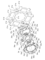
低剛性ダンパ11は、図8及び図9に示すように、第1入力プレートとしてのサブプレート34及び第2入力プレートとしてのスプリングホルダ35と、出力プレートとしてのドライブプレート36と、弾性部材としての複数の低剛性スプリング37と、を有している。
<Low rigidity damper 11>
As shown in FIGS. 8 and 9, the low-rigidity damper 11 includes a sub-plate 34 as a first input plate, a spring holder 35 as a second input plate, a drive plate 36 as an output plate, and an elastic member. It has a plurality of low-rigidity springs 37.

-サブプレート34-
サブプレート34は、クラッチプレート24とハブフランジ21との軸方向間に配置され、ほぼ矩形であって、角部が円弧状に形成されている。サブプレート34は、図9に示すように、中央部に円形の開口を有しており、それぞれ2個の第1保持部34a及び第2保持部34bと、4個の第1係合突起34cと、第1係合突起34cより突起長さが短い4個の第2係合突起34dと、環状溝34eと、を有している。
-Sub-plate 34-
The sub-plate 34 is arranged between the clutch plate 24 and the hub flange 21 in the axial direction, is substantially rectangular, and has corners formed in an arc shape. As shown in FIG. 9, the sub-plate 34 has a circular opening in the central portion, and has two first holding portions 34a and a second holding portion 34b, and four first engaging protrusions 34c, respectively. And four second engaging protrusions 34d having a protrusion length shorter than that of the first engaging protrusion 34c, and an annular groove 34e.

第1保持部34a及び第2保持部34bは、各係合突起34cの内周側に形成されている。4個の第1係合突起34cは、4つの角部外周にハブフランジ21側に突出して形成されている。環状溝34eは第1保持部34a及び第2保持部34bの内周側で、開口部の縁に形成されている。 The first holding portion 34a and the second holding portion 34b are formed on the inner peripheral side of each engaging protrusion 34c. The four first engaging protrusions 34c are formed so as to project toward the hub flange 21 on the outer periphery of the four corners. The annular groove 34e is formed on the inner peripheral side of the first holding portion 34a and the second holding portion 34b at the edge of the opening.

-スプリングホルダ35-
スプリングホルダ35は、サブプレート34とハブフランジ21との軸方向間で、サブプレート34と間隔をあけて対向して配置されている。スプリングホルダ35はサブプレート34とほぼ同様の形状である。スプリングホルダ35は、中央部に円形の開口を有しており、それぞれ2個の第1保持部35a及び第2保持部35bと、4個のボス部35cと、4個の切欠35dと、を有している。各ボス部35cには切欠35eが形成されている。また、第2保持部35bの円周方向両端には、円周方向に延びる円弧状溝35fが形成されている。
-Spring holder 35-
The spring holder 35 is arranged so as to face the sub-plate 34 at a distance from the sub-plate 34 in the axial direction between the sub-plate 34 and the hub flange 21. The spring holder 35 has almost the same shape as the sub plate 34. The spring holder 35 has a circular opening in the central portion, and has two first holding portions 35a and a second holding portion 35b, four boss portions 35c, and four notches 35d, respectively. Have. A notch 35e is formed in each boss portion 35c. Further, arcuate grooves 35f extending in the circumferential direction are formed at both ends of the second holding portion 35b in the circumferential direction.

第1保持部35a及び第2保持部35bは、それぞれサブプレート34の第1保持部34a及び第2保持部34bと対向する位置に形成されている。4個のボス部35cは、4つの角部外周に形成されている。この4個のボス部35cの切欠35eにサブプレート34の第1係合突起34cが係合し、さらにボス部35cがハブフランジ21の係合孔21eに係合している。切欠35dは、サブプレート34の第2係合突起34dに対応して形成されており、この切欠35dに第2係合突起34dが係合している。 The first holding portion 35a and the second holding portion 35b are formed at positions facing the first holding portion 34a and the second holding portion 34b of the sub-plate 34, respectively. The four boss portions 35c are formed on the outer circumferences of the four corner portions. The first engaging projection 34c of the sub-plate 34 is engaged with the notches 35e of the four boss portions 35c, and the boss portion 35c is further engaged with the engaging hole 21e of the hub flange 21. The notch 35d is formed corresponding to the second engaging protrusion 34d of the sub-plate 34, and the second engaging protrusion 34d is engaged with the notch 35d.

以上のように、サブプレート34とスプリングホルダ35とが、第1係合突起34cと切欠35eとの係合、及び第2係合突起34dと切欠35dとの係合、によって一体化されている。そして、スプリングホルダ35とハブフランジ21とが、第1係合突起34c及びボス部35cと係合孔21eとの係合によって一体化されている。したがって、サブプレート34及びスプリングホルダ35はハブフランジ21と一体に回転する。 As described above, the sub-plate 34 and the spring holder 35 are integrated by the engagement between the first engaging protrusion 34c and the notch 35e and the engagement between the second engaging protrusion 34d and the notch 35d. .. The spring holder 35 and the hub flange 21 are integrated by engaging the first engaging protrusion 34c, the boss portion 35c, and the engaging hole 21e. Therefore, the sub-plate 34 and the spring holder 35 rotate integrally with the hub flange 21.

-ドライブプレート36-
ドライブプレート36は、サブプレート34とスプリングホルダ35との軸方向間に配置され、サブプレート34及びスプリングホルダ35と所定の角度範囲内で相対回転可能である。ドライブプレート36は、中央部に開口を有しており、それぞれ2個の第1窓孔36a及び第2窓孔36bと、ドライブプレート36の内周面に形成された複数の係合凹部36cと、を有している。
-Drive plate 36-
The drive plate 36 is arranged between the sub-plate 34 and the spring holder 35 in the axial direction, and can rotate relative to the sub-plate 34 and the spring holder 35 within a predetermined angle range. The drive plate 36 has an opening in the central portion, and has two first window holes 36a and a second window hole 36b, respectively, and a plurality of engaging recesses 36c formed on the inner peripheral surface of the drive plate 36. ,have.

また、第1窓孔36aの内周端部の両側には、それぞれ円周方向に延びる第1係合溝36dが形成されている。第2窓孔36bの内周端部の一方側には、円周方向に延びる第2係合溝36eが形成されている。 Further, first engaging grooves 36d extending in the circumferential direction are formed on both sides of the inner peripheral end portion of the first window hole 36a. A second engaging groove 36e extending in the circumferential direction is formed on one side of the inner peripheral end portion of the second window hole 36b.

第1窓孔36a及び第2窓孔36bは、それぞれサブプレート34及びスプリングホルダ35の第1保持部34a,35a及び第2保持部34b,35bと対向する位置に形成されている。そして、第1窓孔36aに第1低剛性スプリング37aが収容され、この第1低剛性スプリング37aがサブプレート34及びスプリングホルダ35の第1保持部34a,35aによって軸方向及び径方向に保持されている。また、第2窓孔36bに第2低剛性スプリング37bが収容され、この第2低剛性スプリング37bがサブプレート34及びスプリングホルダ35の第2保持部34b,35bによって軸方向及び径方向に保持されている。 The first window hole 36a and the second window hole 36b are formed at positions facing the first holding portions 34a and 35a and the second holding portions 34b and 35b of the sub-plate 34 and the spring holder 35, respectively. A first low-rigidity spring 37a is housed in the first window hole 36a, and the first low-rigidity spring 37a is held axially and radially by the sub-plate 34 and the first holding portions 34a and 35a of the spring holder 35. ing. Further, a second low-rigidity spring 37b is housed in the second window hole 36b, and the second low-rigidity spring 37b is held axially and radially by the sub-plate 34 and the second holding portions 34b and 35b of the spring holder 35. ing.

なお、サブプレート34及びスプリングホルダ35の第1保持部34a,35a及び第2保持部34b,35bの円周方向の両端は、各低剛性スプリング37a,37bの端面に係合可能である。 Both ends of the first holding portions 34a, 35a and the second holding portions 34b, 35b of the sub-plate 34 and the spring holder 35 in the circumferential direction can be engaged with the end faces of the low-rigidity springs 37a, 37b.

ここで、ドライブプレート36の第1窓孔36aには第1低剛性スプリング37aが、第2窓孔36bには第2低剛性スプリング37bが、それぞれ円周方向に隙間なく配置されている。一方、サブプレート34及びスプリングホルダ35の第1保持部34a,35aには第1低剛性スプリング37aが円周方向に隙間なく配置されているが、両部材34,35の第2保持部34b,35bには、第2低剛性スプリング37bが円周方向に隙間を介して配置されている。この隙間が1段目の捩り角度分(低捩り角度領域L1)に相当している。 Here, the first low-rigidity spring 37a is arranged in the first window hole 36a of the drive plate 36, and the second low-rigidity spring 37b is arranged in the second window hole 36b without any gap in the circumferential direction. On the other hand, although the first low-rigidity spring 37a is arranged in the first holding portions 34a and 35a of the sub-plate 34 and the spring holder 35 without any gap in the circumferential direction, the second holding portions 34b of both members 34 and 35, A second low-rigidity spring 37b is arranged in the 35b with a gap in the circumferential direction. This gap corresponds to the twist angle of the first stage (low twist angle region L1).

低剛性スプリング37のバネ定数は、高剛性スプリング22のバネ定数に比べて大幅に小さく設定されている。すなわち、高剛性スプリング22は低剛性スプリング37よりもはるかに剛性が高い。このため、1段目領域(L1)及び2段目領域(L2)では、高剛性スプリング22は圧縮されず、低剛性スプリング37のみが圧縮される。 The spring constant of the low-rigidity spring 37 is set to be significantly smaller than the spring constant of the high-rigidity spring 22. That is, the high-rigidity spring 22 is much more rigid than the low-rigidity spring 37. Therefore, in the first-stage region (L1) and the second-stage region (L2), the high-rigidity spring 22 is not compressed, and only the low-rigidity spring 37 is compressed.

[スプラインハブ4]
スプラインハブ4は、クラッチプレート24及びリティニングプレート25の内周側に配置されている。スプラインハブ4は、図4及び図8に示すように、軸方向に延びる筒状のボス41と、ボス41から径方向外側に延びるフランジ42と、を有している。ボス41の内周部には、トランスミッションの入力シャフト(図示せず)に係合するスプライン孔4aが形成されている。
[Spline Hub 4]
The spline hub 4 is arranged on the inner peripheral side of the clutch plate 24 and the reinforcement plate 25. As shown in FIGS. 4 and 8, the spline hub 4 has a cylindrical boss 41 extending in the axial direction and a flange 42 extending radially outward from the boss 41. A spline hole 4a that engages with an input shaft (not shown) of a transmission is formed in the inner peripheral portion of the boss 41.

ボス41の外周面において、フランジ42のエンジン側には複数の係合凸部4dが形成されている。係合凸部4dはドライブプレート36の係合凹部36cに、実質的に隙間なく係合している。また、フランジ42の外周面には、歯4cが形成されている。図5で説明したように、この歯4cが、ハブフランジ21の歯21cと噛合可能であり、両歯4c,21cの円周方向間には隙間G1が存在する。 On the outer peripheral surface of the boss 41, a plurality of engaging protrusions 4d are formed on the engine side of the flange 42. The engaging convex portion 4d is engaged with the engaging concave portion 36c of the drive plate 36 substantially without a gap. Further, teeth 4c are formed on the outer peripheral surface of the flange 42. As described with reference to FIG. 5, this tooth 4c can mesh with the tooth 21c of the hub flange 21, and a gap G1 exists between the circumferential directions of both teeth 4c and 21c.

<L-Hヒス発生機構13>
L-Hヒス発生機構13は、捩り角度領域の全領域(L1+L2+H3+H4)においてヒステリシストルクHを発生する。
<LH hiss generation mechanism 13>
The LH hiss generation mechanism 13 generates the hysteresis torque H in the entire region (L1 + L2 + H3 + H4) of the twist angle region.

L-Hヒス発生機構13は、図8に示すように、第1摩擦ワッシャ51と、第2摩擦ワッシャ52と、第1コーンスプリング54と、を有している。 As shown in FIG. 8, the LH hiss generating mechanism 13 has a first friction washer 51, a second friction washer 52, and a first cone spring 54.

第1摩擦ワッシャ51は、樹脂製であり、スプラインハブ4のボス41の外周において、係合凸部4dの側面とクラッチプレート24の内周端部との間に配置されている。 The first friction washer 51 is made of resin and is arranged on the outer periphery of the boss 41 of the spline hub 4 between the side surface of the engaging convex portion 4d and the inner peripheral end portion of the clutch plate 24.

第2摩擦ワッシャ52は、樹脂製であり、スプラインハブ4のフランジ42とリティニングプレート25の内周端部との軸方向間に配置されている。第2摩擦ワッシャ52の外周部には、後述する第3摩擦ワッシャ53に係合する係合部(図示せず)を有しており、両部材は一体回転する。 The second friction washer 52 is made of resin and is arranged between the flange 42 of the spline hub 4 and the inner peripheral end portion of the linting plate 25 in the axial direction. The outer peripheral portion of the second friction washer 52 has an engaging portion (not shown) that engages with the third friction washer 53, which will be described later, and both members rotate integrally.

また、第1コーンスプリング54は、第2摩擦ワッシャ52とリティニングプレート25の内周端部との軸方向間に配置され、第2摩擦ワッシャ52とリティニングプレート25とが互いに離れるように、両部材25,52を付勢している。 Further, the first cone spring 54 is arranged between the second friction washer 52 and the inner peripheral end portion of the linting plate 25 in the axial direction so that the second friction washer 52 and the linting plate 25 are separated from each other. Both members 25 and 52 are urged.

以上から、クラッチプレート24及びリティニングプレート25と、スプラインハブ4と、が相対回転する全捩り角度領域において、第1摩擦ワッシャ51とクラッチプレート24又はスプラインハブ4との間に摩擦抵抗が発生するとともに、第2摩擦ワッシャ52とスプラインハブ4との間に摩擦抵抗が発生する。これらの摩擦抵抗によって、全捩り角度領域においてヒステリシストルクHが発生する。 From the above, frictional resistance is generated between the first friction washer 51 and the clutch plate 24 or the spline hub 4 in the total twist angle region where the clutch plate 24, the leaning plate 25, and the spline hub 4 rotate relative to each other. At the same time, frictional resistance is generated between the second friction washer 52 and the spline hub 4. Due to these frictional resistances, a hysteresis torque H is generated in the entire torsion angle region.

<Lヒス発生機構14>
Lヒス発生機構14は、1段目領域及び2段目領域である低捩り角度領域の全領域(L1+L2)でのみヒステリシストルクhLを発生する。
<L hiss generation mechanism 14>
The L hiss generation mechanism 14 generates the hysteresis torque hL only in the entire region (L1 + L2) of the low twist angle region, which is the first stage region and the second stage region.

Lヒス発生機構14は、図9及び図10に示すように、サブプレート34の環状溝34eに装着された付勢部材56を有している。付勢部材56は座面部56a及び付勢部56bを有している。座面部56a及び付勢部56bは、連続する線材で形成されている。 As shown in FIGS. 9 and 10, the L-his generation mechanism 14 has an urging member 56 mounted in the annular groove 34e of the sub-plate 34. The urging member 56 has a seat surface portion 56a and an urging portion 56b. The seat surface portion 56a and the urging portion 56b are formed of continuous wire rods.

具体的には、座面部56aは、一部に欠落部(始端と終端部との間)を有する環状かつ軸方向に凹凸のない平坦状に形成され、一方の面の全体が環状溝34eの底面に当接している。付勢部56bは、座面部56aの円周方向の終端部から連続して環状に形成されている。付勢部56bは、凹凸を有する波形に形成され、円周方向に所定の間隔で複数の押圧部56cを有している。押圧部56cは、ドライブプレート36側に突出して形成された凸部であり、弾性変形が可能である。また、押圧部56cの先端部は、ドライブプレート36の各窓孔36a,36bに形成された第1及び第2係合溝36d,36eに係合可能である。このように、付勢部材56は、ドライブプレート36に対して相対回転不能であり、環状溝34e内で円周方向に移動可能である。そして、押圧部56cの弾性変形によって、ドライブプレート36がスプリングホルダ35側に付勢されている。 Specifically, the bearing surface portion 56a is formed in an annular shape having a partially missing portion (between the start end and the end portion) and has no unevenness in the axial direction, and the entire one surface of the annular groove 34e is formed. It is in contact with the bottom surface. The urging portion 56b is formed in an annular shape continuously from the distal end portion of the seat surface portion 56a in the circumferential direction. The urging portion 56b is formed in a corrugated shape having irregularities, and has a plurality of pressing portions 56c at predetermined intervals in the circumferential direction. The pressing portion 56c is a convex portion formed so as to project toward the drive plate 36 side, and can be elastically deformed. Further, the tip portion of the pressing portion 56c can be engaged with the first and second engaging grooves 36d and 36e formed in the window holes 36a and 36b of the drive plate 36. As described above, the urging member 56 cannot rotate relative to the drive plate 36 and can move in the circumferential direction in the annular groove 34e. The drive plate 36 is urged toward the spring holder 35 by the elastic deformation of the pressing portion 56c.

なお、複数の押圧部56cの円周方向間に形成された凹部の先端は、座面部56aの表面に当接している。 The tips of the recesses formed between the circumferential directions of the plurality of pressing portions 56c are in contact with the surface of the seat surface portion 56a.

ここで、前述のように、サブプレート34及びスプリングホルダ35はハブフランジ21と一体回転する。また、ドライブプレート36はスプラインハブ4と一体回転する。そして、ハブフランジ21とスプラインハブ4とは、前述のように、隙間G1の角度分だけ相対回転可能である。言い換えれば、ハブフランジ21(スプリングホルダ35と一体回転)とスプラインハブ4(ドライブプレート36と一体回転)とは、捩り特性の1段目領域と2段目領域の低捩り角度領域の全領域(L1+L2)においてのみ相対回転可能である。 Here, as described above, the sub-plate 34 and the spring holder 35 rotate integrally with the hub flange 21. Further, the drive plate 36 rotates integrally with the spline hub 4. As described above, the hub flange 21 and the spline hub 4 can rotate relative to each other by the angle of the gap G1. In other words, the hub flange 21 (integral rotation with the spring holder 35) and the spline hub 4 (integral rotation with the drive plate 36) are the entire region of the low torsion angle region of the first stage region and the second stage region of the torsion characteristics (integral rotation with the spring holder 35). Relative rotation is possible only in L1 + L2).

そして、スプリングホルダ35とドライブプレート36とは、付勢部材56によって互いに押圧されているので、スプリングホルダ35とドライブプレート36とは低捩り角度の全領域(L1+L2)においてのみ相対回転して摩擦抵抗が生じる。また、付勢部材56とサブプレート34の環状溝34eの底部との間にも摩擦抵抗が生じる。これらの摩擦抵抗によって、ヒステリシストルクhLが発生する。 Since the spring holder 35 and the drive plate 36 are pressed against each other by the urging member 56, the spring holder 35 and the drive plate 36 rotate relative to each other only in the entire region (L1 + L2) having a low twist angle, and frictional resistance. Occurs. Further, frictional resistance is also generated between the urging member 56 and the bottom of the annular groove 34e of the sub-plate 34. Hysteresis torque hL is generated by these frictional resistances.

ここでは、サブプレート34の環状溝34eに付勢部材56が埋め込まれるように装着されているので、軸方向寸法を抑えて、ヒステリシストルク発生機構を実現できる。また、スプリングホルダ35とドライブプレート36との間だけではなく、付勢部材56の座面部56aとサブプレート34の環状溝34eの底部との間にも摩擦抵抗が生じるので、各部における摩擦抵抗を小さくして所望のヒステリシストルクが得られる。したがって、各部の磨耗を抑えることができる。 Here, since the urging member 56 is mounted so as to be embedded in the annular groove 34e of the sub-plate 34, it is possible to suppress the axial dimension and realize the hysteresis torque generation mechanism. Further, since frictional resistance is generated not only between the spring holder 35 and the drive plate 36 but also between the seat surface portion 56a of the urging member 56 and the bottom portion of the annular groove 34e of the sub-plate 34, the frictional resistance in each portion is increased. The desired hysteresis torque can be obtained by reducing the size. Therefore, wear of each part can be suppressed.

さらに、付勢部材56は、座面部56aの全体が環状溝34eの底面に摺接する。したがって、座面部56aと環状溝34eの底面との間の面圧を抑えることができる。このため、座面部56a及び環状溝34eの底面の摩耗を抑えることができ、結果として、高いヒステリシストルクを設定することができる。 Further, in the urging member 56, the entire seat surface portion 56a is in sliding contact with the bottom surface of the annular groove 34e. Therefore, the surface pressure between the seat surface portion 56a and the bottom surface of the annular groove 34e can be suppressed. Therefore, wear of the bottom surface of the seat surface portion 56a and the annular groove 34e can be suppressed, and as a result, a high hysteresis torque can be set.

<L2ヒス発生機構15>
L2ヒス発生機構15は、2段目の捩り角度領域(L2)でのみヒステリシストルクhL2を発生する。
<L2 hiss generation mechanism 15>
The L2 hiss generation mechanism 15 generates the hysteresis torque hL2 only in the twist angle region (L2) of the second stage.

L2ヒス発生機構15はウェーブスプリング60を有している。ウェーブスプリング60は、軸方向に弾性変形可能な環状の弾性体であり、軸方向に圧縮された状態でスプラインハブ4のフランジ42とスプリングホルダ35との間に配置されている。ウェーブスプリング60は、ハブフランジ21及びスプリングホルダ35に当接しており、ハブフランジ21に対して回転すると摩擦抵抗を発生する。 The L2 hiss generating mechanism 15 has a wave spring 60. The wave spring 60 is an annular elastic body that can be elastically deformed in the axial direction, and is arranged between the flange 42 of the spline hub 4 and the spring holder 35 in a state of being compressed in the axial direction. The wave spring 60 is in contact with the hub flange 21 and the spring holder 35, and when rotated with respect to the hub flange 21, frictional resistance is generated.

図11に、ウェーブスプリング60及びその周辺の部材を抽出して示している。ウェーブスプリング60は、環状の本体部60aと、本体部60aから径方向外側へ延びる2対の爪部60bと、を有している。爪部60bの先端部は、軸方向に折り曲げられており、スプリングホルダ35に形成された円弧状溝35fを通過して第2低剛性スプリング37bの両端部に当接している。2つの爪部60b間の円周方向の距離は、第2低剛性スプリング37bの自由長とほぼ一致している。これにより、第2低剛性スプリング37bによりウェーブスプリング60の円周(回転)方向の位置決めが行われるとともに、第2低剛性スプリング37b及びウェーブスプリング60は一体で回転可能となっている。なお、溝35fの円周方向の距離は、2つの爪部60b間の円周方向の距離より長い。 FIG. 11 shows the wave spring 60 and its peripheral members extracted. The wave spring 60 has an annular main body portion 60a and two pairs of claw portions 60b extending radially outward from the main body portion 60a. The tip of the claw portion 60b is bent in the axial direction, passes through the arcuate groove 35f formed in the spring holder 35, and abuts on both ends of the second low-rigidity spring 37b. The circumferential distance between the two claws 60b is substantially the same as the free length of the second low-rigidity spring 37b. As a result, the second low-rigidity spring 37b positions the wave spring 60 in the circumferential (rotational) direction, and the second low-rigidity spring 37b and the wave spring 60 can rotate integrally. The distance in the circumferential direction of the groove 35f is longer than the distance in the circumferential direction between the two claw portions 60b.

また、本体部60aの内周部には、複数の係合凹部60cが形成されている。係合凹部60cは、スプラインハブ4の係合凸部4dに所定の隙間を介して係合している。この隙間が、1段目の捩り角度領域(L1)の角度分に相当している。したがって、1段目領域ではウェーブスプリング60によるヒステリシストルクは発生しないが、2段目領域(L2)でのみウェーブスプリング60によるヒステリシストルクhL2が得られる。 Further, a plurality of engaging recesses 60c are formed in the inner peripheral portion of the main body portion 60a. The engaging recess 60c is engaged with the engaging convex portion 4d of the spline hub 4 via a predetermined gap. This gap corresponds to the angle of the twist angle region (L1) of the first stage. Therefore, the hysteresis torque due to the wave spring 60 is not generated in the first stage region, but the hysteresis torque hL2 due to the wave spring 60 can be obtained only in the second stage region (L2).

<Hヒス発生機構16>
Hヒス発生機構16は、3段目領域及び4段目領域である高捩り角度領域(H3+H4)でのみヒステリシストルクhHを発生する。
<H hiss generation mechanism 16>
The H hiss generation mechanism 16 generates the hysteresis torque hH only in the high torsion angle region (H3 + H4) which is the third stage region and the fourth stage region.

Hヒス発生機構16は、図4及び図8に示すように、サブプレート34に装着された環状の第1摩擦材61と、環状の第2摩擦材62を有する第3摩擦ワッシャ53と、第2コーンスプリング64と、を有している。 As shown in FIGS. 4 and 8, the H-his generation mechanism 16 includes an annular first friction material 61 mounted on the sub-plate 34, a third friction washer 53 having an annular second friction material 62, and a first friction washer 53. It has two cone springs 64 and.

第1摩擦材61は、サブプレート34のエンジン側の側面に固定されており、クラッチプレート24の内周部の側面に当接可能である。第1摩擦材61はサブプレート34とともにハブフランジ21と一体回転する。 The first friction material 61 is fixed to the side surface of the sub-plate 34 on the engine side, and can come into contact with the side surface of the inner peripheral portion of the clutch plate 24. The first friction material 61 rotates integrally with the hub flange 21 together with the sub-plate 34.

第3摩擦ワッシャ53は、ハブフランジ21内周部とリティニングプレート25内周部との間に配置されており、リティニングプレート25側に突出する複数の係合突起53aを有している。この係合突起53aがリティニングプレート25の係合孔25cに係合している。したがって、第3摩擦ワッシャ53はリティニングプレート25と一体回転する。第2摩擦材62は、第3摩擦ワッシャ53のハブフランジ21側の側面に固定され、ハブフランジ21の内周部の側面に当接可能である。 The third friction washer 53 is arranged between the inner peripheral portion of the hub flange 21 and the inner peripheral portion of the linting plate 25, and has a plurality of engaging protrusions 53a protruding toward the linting plate 25 side. The engaging protrusion 53a is engaged with the engaging hole 25c of the linting plate 25. Therefore, the third friction washer 53 rotates integrally with the linting plate 25. The second friction material 62 is fixed to the side surface of the third friction washer 53 on the hub flange 21 side, and can come into contact with the side surface of the inner peripheral portion of the hub flange 21.

第2コーンスプリング64は、第3摩擦ワッシャ53とリティニングプレート25との間に配置されている。第2コーンスプリング64は、第3摩擦ワッシャ53とリティニングプレート25とを、両者が軸方向に互いに離れる方向に付勢している。したがって、第2コーンスプリング64により、第1摩擦材61とクラッチプレート24とが互いに押圧され、第2摩擦材62とハブフランジ21とが互いに押圧される。 The second cone spring 64 is arranged between the third friction washer 53 and the linting plate 25. The second cone spring 64 urges the third friction washer 53 and the linting plate 25 in a direction in which they are axially separated from each other. Therefore, the second friction material 61 and the clutch plate 24 are pressed against each other by the second cone spring 64, and the second friction material 62 and the hub flange 21 are pressed against each other.

以上から、クラッチプレート24及びリティニングプレート25と、ハブフランジ21と、が相対回転する高捩り角度領域の全領域(H3+H4)において、第1摩擦材61とクラッチプレート24との間、及び第2摩擦材62とハブフランジ21との間において摩擦抵抗が生じる。これらの摩擦抵抗によって、ヒステリシストルクhHが発生する。 From the above, in the entire region (H3 + H4) of the high torsional angle region where the clutch plate 24, the leaning plate 25, and the hub flange 21 rotate relative to each other, between the first friction material 61 and the clutch plate 24, and the second. Friction resistance occurs between the friction material 62 and the hub flange 21. Hysteresis torque hH is generated by these frictional resistances.

以上をまとめると、図3に示すように、各角度領域では以下のようなヒステリシストルクが発生する。 Summarizing the above, as shown in FIG. 3, the following hysteresis torques are generated in each angle region.

1段目領域(L1):H(L-Hヒス発生機構13)+hL(Lヒス発生機構14)
2段目領域(L2):H+hL+hL2(L2ヒス発生機構15)
3段目領域及び4段目領域(H3+H4):H+hH(Hヒス発生機構16)
以上のヒステリシストルク発生機構13~16によるヒステリシストルクについて、低捩り角度領域(L1+L2)におけるL-Hヒス発生機構13によるヒステリシストルクHと、Lヒス発生機構14によるヒステリシストルクhLと、の割合は、ヒステリシストルクhLが50%以上であることが望ましい。
First stage region (L1): H (L—H hiss generation mechanism 13) + hL (L hiss generation mechanism 14)
Second stage region (L2): H + hL + hL2 (L2 hiss generation mechanism 15)
3rd stage region and 4th stage region (H3 + H4): H + hH (H hiss generation mechanism 16)
Regarding the hysteresis torque by the above-mentioned hysteresis torque generation mechanisms 13 to 16, the ratio of the hysteresis torque H by the LH hiss generation mechanism 13 and the hysteresis torque hL by the L hiss generation mechanism 14 in the low torsion angle region (L1 + L2) is It is desirable that the hysteresis torque hL is 50% or more.

[動作]
本実施形態のクラッチディスク組立体1の捩り特性は、角度範囲の大きさは異なるが基本的に正側と負側とで対称である。したがって、ここでは正側のみの動作を説明し、負側の動作についての説明は省略する。
[motion]
The torsional characteristics of the clutch disc assembly 1 of the present embodiment are basically symmetrical between the positive side and the negative side, although the size of the angle range is different. Therefore, here, the operation of only the positive side will be described, and the description of the operation of the negative side will be omitted.

<1段目>
伝達トルク及びトルク変動が小さい場合は、本装置は捩り特性の1段目(L1)で作動する。この1段目では、剛性の低い第1及び第2低剛性スプリング37a,37bのうち、自由長が長い第1低剛性スプリング37aのみが圧縮される。このため、サブプレート34及びスプリングホルダ35と、ドライブプレート36と、が相対回転する。一方で、第1及び第2高剛性スプリング22a,22bは剛性が高いためにほとんど圧縮されない。したがって、入力側回転部材20(クラッチプレート24及びリティニングプレート25)とハブフランジ21とは一体回転する。
<1st stage>
When the transmission torque and torque fluctuation are small, this device operates in the first stage (L1) of the torsion characteristics. In this first stage, of the low-rigidity first and second low-rigidity springs 37a and 37b, only the first low-rigidity spring 37a having a long free length is compressed. Therefore, the sub-plate 34, the spring holder 35, and the drive plate 36 rotate relative to each other. On the other hand, the first and second high-rigidity springs 22a and 22b are hardly compressed due to their high rigidity. Therefore, the input side rotating member 20 (clutch plate 24 and leaning plate 25) and the hub flange 21 rotate integrally.

以上から、捩り特性の1段目では、{入力側回転体2+ハブフランジ21+サブプレート34+スプリングホルダ35}が一体回転し、これらの部材に対して{ドライブプレート36+スプラインハブ4}が回転する。 From the above, in the first stage of the twisting characteristic, {input side rotating body 2 + hub flange 21 + sub-plate 34 + spring holder 35} rotates integrally, and {drive plate 36 + spline hub 4} rotates with respect to these members.

この場合は、L-Hヒス発生機構13によるヒステリシストルクHと、Lヒス発生機構14によるヒステリシストルクhLとが発生する。具体的には、第1摩擦ワッシャ51とクラッチプレート24又はスプラインハブ4との間、及び第2摩擦ワッシャ52とスプラインハブ4との間、において摩擦抵抗が発生する。また、同時に、付勢部材56とサブプレート34との間、及びドライブプレート36とスプリングホルダ35との間においても摩擦抵抗が発生する。 In this case, the hysteresis torque H by the LH hiss generation mechanism 13 and the hysteresis torque hL by the L hiss generation mechanism 14 are generated. Specifically, frictional resistance is generated between the first friction washer 51 and the clutch plate 24 or the spline hub 4, and between the second friction washer 52 and the spline hub 4. At the same time, frictional resistance is also generated between the urging member 56 and the sub-plate 34 , and between the drive plate 36 and the spring holder 35.

なお、ウェーブスプリング60は爪部60bが第2低剛性スプリング37bに係合しているので、この1段目ではウェーブスプリング60は自由に回転し得る状態であり、ウェーブスプリング60とハブフランジ21との間には摩擦抵抗は発生しない。 Since the claw portion 60b of the wave spring 60 is engaged with the second low-rigidity spring 37b, the wave spring 60 is in a state where it can freely rotate in the first stage, and the wave spring 60 and the hub flange 21 No frictional resistance is generated between them.

<2段目>
伝達トルク又はトルク変動がより大きくなると、第1低剛性スプリング37aが圧縮されつつ、さらに自由長の短い第2低剛性スプリング37bも圧縮され始める。第1低剛性スプリング37aと第2低剛性スプリング37bとは並列に配置されているので、第2低剛性スプリング37bが圧縮され始めると、第1低剛性スプリング37aのみが圧縮されている場合(1段目)に比較して捩り剛性は高くなる。すなわち、捩り特性の2段目に移行する。
<2nd stage>
When the transmission torque or the torque fluctuation becomes larger, the first low-rigidity spring 37a is compressed, and the second low-rigidity spring 37b having a shorter free length also begins to be compressed. Since the first low-rigidity spring 37a and the second low-rigidity spring 37b are arranged in parallel, when the second low-rigidity spring 37b begins to be compressed, only the first low-rigidity spring 37a is compressed (1). The torsional rigidity is higher than that of the step). That is, it shifts to the second stage of the twisting characteristic.

この2段目においては、1段目と同様のヒステリシストルク発生機構13,14に加えて、L2ヒス発生機構15が作動する。 In this second stage, the L2 hiss generation mechanism 15 operates in addition to the hysteresis torque generation mechanisms 13 and 14 similar to those in the first stage.

すなわち、1段目と同様の部材間に摩擦抵抗が発生するとともに、ウェーブスプリング60とハブフランジ21との間においても摩擦抵抗が発生する。具体的には、第2低剛性スプリング37bが圧縮されると、第2低剛性スプリング37bが圧縮された分だけウェーブスプリング60がハブフランジ21に対して回転し、両部材60,21間に摩擦抵抗が発生する。したがって、2段目においては、1段目と同様のヒステリシストルクH+hLに加えて、ウェーブスプリング60とハブフランジ21との間の摩擦抵抗によるヒステリシストルクhL2が発生する。 That is, frictional resistance is generated between the same members as in the first stage, and frictional resistance is also generated between the wave spring 60 and the hub flange 21. Specifically, when the second low-rigidity spring 37b is compressed, the wave spring 60 rotates with respect to the hub flange 21 by the amount of compression of the second low-rigidity spring 37b, and friction is applied between both members 60 and 21. Resistance is generated. Therefore, in the second stage, in addition to the same hysteresis torque H + hL as in the first stage, the hysteresis torque hL2 due to the frictional resistance between the wave spring 60 and the hub flange 21 is generated.

<3段目>
伝達トルク又はトルク変動がさらに大きくなると、第1及び第2低剛性スプリング37a,37bがさらに圧縮され、スプラインハブ4に対して入力側回転部材20がさらに回転する。すると、ハブフランジ21の歯21cとスプラインハブ4の歯4cとが当接し、ハブフランジ21とスプラインハブ4とは一体に回転することになる。この状態では、第1及び第2低剛性スプリング37a,37bは先の状態以上に圧縮されることはなく、高剛性スプリング22のうちの自由長の長い第1高剛性スプリング22aの圧縮が開始される。第1高剛性スプリング22aは第1及び第2低剛性スプリング37a,37bよりも剛性が高いので、2段目よりもさらに高い3段目の捩り剛性が得られる。
<Third stage>
When the transmission torque or the torque fluctuation becomes larger, the first and second low-rigidity springs 37a and 37b are further compressed, and the input-side rotating member 20 further rotates with respect to the spline hub 4. Then, the teeth 21c of the hub flange 21 and the teeth 4c of the spline hub 4 come into contact with each other, and the hub flange 21 and the spline hub 4 rotate integrally. In this state, the first and second low-rigidity springs 37a and 37b are not compressed more than the previous state, and the compression of the first high-rigidity spring 22a having a long free length among the high-rigidity springs 22 is started. To. Since the first high-rigidity spring 22a has higher rigidity than the first and second low-rigidity springs 37a and 37b, a third-stage torsional rigidity higher than that of the second-stage can be obtained.

3段目においては、第1高剛性スプリング22aが圧縮されるので、入力側回転部材20とハブフランジ21(及びスプラインハブ4)との間で相対回転が発生する。一方で、リティニングプレート25と第3摩擦ワッシャ53とは一体回転し、ハブフランジ21とサブプレート34とは一体回転する。したがって、この3段目では、L-Hヒス発生機構13及びHヒス発生機構16が作動する。 In the third stage, the first high-rigidity spring 22a is compressed, so that relative rotation occurs between the input-side rotating member 20 and the hub flange 21 (and the spline hub 4). On the other hand, the reinforcement plate 25 and the third friction washer 53 rotate integrally, and the hub flange 21 and the sub-plate 34 rotate integrally. Therefore, in this third stage, the LH hiss generating mechanism 13 and the H hiss generating mechanism 16 operate.

すなわち、第3摩擦ワッシャ53に固定された第2摩擦材62とハブフランジ21との間で摩擦抵抗が発生する。また、サブプレート34に固定された第1摩擦材61とクラッチプレート24との間で摩擦抵抗が発生する。これらの摩擦抵抗によって、ヒステリシストルクhHが発生する。すなわち、合計でヒステリシストルクH+hHが発生する。 That is, frictional resistance is generated between the second friction material 62 fixed to the third friction washer 53 and the hub flange 21. Further, frictional resistance is generated between the first friction material 61 fixed to the sub-plate 34 and the clutch plate 24. Hysteresis torque hH is generated by these frictional resistances. That is, a total hysteresis torque H + hH is generated.

ここで、この3段目では、サブプレート34及びスプリングホルダ35と、ドライブプレート36と、は相対回転せず、これらの部材の間では摩擦抵抗は発生しない。すなわち、Lヒス発生機構14及びL2ヒス発生機構15は作動しない。 Here, in this third stage, the sub-plate 34, the spring holder 35, and the drive plate 36 do not rotate relative to each other, and frictional resistance does not occur between these members. That is, the L hiss generating mechanism 14 and the L2 hiss generating mechanism 15 do not operate.

<4段目>
伝達トルク又はトルク変動がさらに大きくなると、第1高剛性スプリング22aが圧縮されつつ、さらに自由長の短い第2高剛性スプリング22bも圧縮され始める。第1高剛性スプリング22aと第2高剛性スプリング22bとは並列に配置されているので、第2高剛性スプリング22bが圧縮され始めると、第1高剛性スプリング22aのみが圧縮されている場合(3段目)に比較して捩り剛性は高くなる。すなわち、捩り特性の4段目に移行する。
<4th stage>
When the transmission torque or the torque fluctuation becomes larger, the first high-rigidity spring 22a is compressed, and the second high-rigidity spring 22b, which has a shorter free length, also begins to be compressed. Since the first high-rigidity spring 22a and the second high-rigidity spring 22b are arranged in parallel, when the second high-rigidity spring 22b begins to be compressed, only the first high-rigidity spring 22a is compressed (3). The torsional rigidity is higher than that of the step). That is, it shifts to the fourth stage of the twisting characteristic.

この4段目において、相対回転する部材は3段目と同様であり、L-Hヒス発生機構13及びHヒス発生機構16が作動し、ヒステリシストルクH+hHが得られる。 In this fourth stage, the relative rotating member is the same as in the third stage, the LH hiss generating mechanism 13 and the H hiss generating mechanism 16 are operated, and the hysteresis torque H + hH is obtained.

<ストッパ機構17の作動>
そして、さらに伝達トルク又はトルク変動が大きくなると、クラッチプレート24及びリティニングプレート25とハブフランジ21との相対回転角度が大きくなる。すると、ストップピン26がストッパ用切欠21dの側面に当接し、クラッチプレート24及びリティニングプレート25とハブフランジ21との相対回転が停止する。
<Operation of stopper mechanism 17>
When the transmission torque or the torque fluctuation becomes larger, the relative rotation angle between the clutch plate 24 and the leaning plate 25 and the hub flange 21 becomes larger. Then, the stop pin 26 comes into contact with the side surface of the stopper notch 21d, and the relative rotation between the clutch plate 24 and the retaining plate 25 and the hub flange 21 is stopped.

[特徴]
以上のように、本実施形態のクラッチディスク組立体1では、以下のような特徴を有している。
[feature]
As described above, the clutch disc assembly 1 of the present embodiment has the following features.

(1)Lヒス発生機構14は、低捩り角度領域でのみヒステリシストルクhLを発生するので、全捩り角度領域で作動する場合に比較して、摩擦部材の摩耗が抑えられる。したがって、低捩り角度領域において、長期にわたり安定したヒステリシストルクが得られ、特にアイドリング時の異音を効果的に抑えることができる。 (1) Since the L hiss generation mechanism 14 generates the hysteresis torque hL only in the low torsional angle region, the wear of the friction member is suppressed as compared with the case of operating in the entire torsional angle region. Therefore, a stable hysteresis torque can be obtained for a long period of time in the low twist angle region, and abnormal noise during idling can be effectively suppressed.

(2)Lヒス発生機構14は、低剛性ダンパ11の構成部材及びサブプレート34の環状溝34eに装着された付勢部材56によって構成されている。したがって、Lヒス発生機構14の軸方向のスペースが抑えられる。 (2) The L hiss generating mechanism 14 is composed of a constituent member of the low-rigidity damper 11 and an urging member 56 mounted in the annular groove 34e of the sub-plate 34. Therefore, the space in the axial direction of the L hiss generating mechanism 14 is suppressed.

また、付勢部材56に座面部56aを設けているので、付勢部材56と環状溝34eとの間の面圧を低く抑えることができる。したがって、高いヒステリシストルクを設定しても、摺接部分の摩耗を抑えて、長期にわたって安定したヒステリシストルクを得ることができる。 Further, since the seating surface portion 56a is provided on the urging member 56, the surface pressure between the urging member 56 and the annular groove 34e can be suppressed to a low level. Therefore, even if a high hysteresis torque is set, it is possible to suppress wear of the sliding contact portion and obtain a stable hysteresis torque for a long period of time.

(3)Lヒス発生機構14に加えて、L-Hヒス発生機構13を設けている。したがって、それぞれのヒス発生機構で発生すべきヒステリシストルクを比較的小さくでき、摩擦部材の摩耗を抑えることができる。 (3) In addition to the L hiss generating mechanism 14, the LH hiss generating mechanism 13 is provided. Therefore, the hysteresis torque that should be generated by each hiss generation mechanism can be made relatively small, and the wear of the friction member can be suppressed.

[他の実施形態]
本発明は以上のような実施形態に限定されるものではなく、本発明の範囲を逸脱することなく種々の変形又は修正が可能である。
[Other embodiments]
The present invention is not limited to the above embodiments, and various modifications or modifications can be made without departing from the scope of the present invention.

(a)前記実施形態では、付勢部材56の座面部56a及び付勢部56bを連続する線材で形成したが、付勢部材56の構成はこれに限定されない。 (A) In the above embodiment, the seat surface portion 56a and the urging portion 56b of the urging member 56 are formed of continuous wire rods, but the configuration of the urging member 56 is not limited to this.

例えば、図12に示す付勢部材70は、座面部71と付勢部72とが別の部材で構成されている。座面部71は、鉄製のワッシャであり、全面が環状溝34eの底面に当接可能である。また、付勢部72は、複数の凹凸を有する鉄製の波線で形成されており、基本的な構成は前記実施形態と同様である。すなわち、複数の押圧部72aを有し、押圧部72aの先端部は、ドライブプレート36の各窓孔36a,36bに形成された第1及び第2係合溝36d,36eに係合している。したがって、付勢部材70は、ドライブプレート36に対して相対回転不能である。そして、押圧部72aの弾性変形によって、ドライブプレート36がスプリングホルダ35側に付勢されている。また、複数の押圧部72aの円周方向間に形成された凹部の先端は、座面部71の表面に当接している。 For example, in the urging member 70 shown in FIG. 12, the seat surface portion 71 and the urging portion 72 are made of different members. The seat surface portion 71 is an iron washer, and the entire surface thereof can come into contact with the bottom surface of the annular groove 34e. Further, the urging portion 72 is formed of a wavy line made of iron having a plurality of irregularities, and the basic configuration is the same as that of the above-described embodiment. That is, it has a plurality of pressing portions 72a, and the tip portions of the pressing portions 72a are engaged with the first and second engaging grooves 36d, 36e formed in the window holes 36a, 36b of the drive plate 36. .. Therefore, the urging member 70 cannot rotate relative to the drive plate 36. Then, the drive plate 36 is urged toward the spring holder 35 by the elastic deformation of the pressing portion 72a. Further, the tips of the recesses formed between the circumferential directions of the plurality of pressing portions 72a are in contact with the surface of the seat surface portion 71.

このような構成では、初期状態においては、座面部71と付勢部72との間で相対すべりが生じる場合がある。しかし、座面部71と付勢部72とは共に鉄製であるので、鉄同士の相対すべりによる摩擦が続くと、これら部材間の摩擦係数が大きくなる。このため、ある程度の作動が続くと、座面部71と環状溝34eとの間で相対すべりが生じ、予定したヒステリシストルクを得ることができる。 In such a configuration, in the initial state, relative slip may occur between the seat surface portion 71 and the urging portion 72. However, since both the seat surface portion 71 and the urging portion 72 are made of iron, if the friction due to the relative slip between the irons continues, the coefficient of friction between these members increases. Therefore, if the operation continues to some extent, a relative slip occurs between the seat surface portion 71 and the annular groove 34e, and a planned hysteresis torque can be obtained.

(b)前記実施形態では、付勢部材56の座面部56aのほぼ全面を環状溝34eの底面に当接させるようにしたが、これに限定されない。すなわち、付勢部材56を付勢部56bのみで形成した場合、押圧部56cの間の凹部先端部のみが環状溝34eに当接することになる。したがって、座面部56aと環状溝34eの底面との接触面積が、この場合(凹部のみが当接する場合)よりも大きくなればよい。 (B) In the above embodiment, almost the entire surface of the seat surface portion 56a of the urging member 56 is brought into contact with the bottom surface of the annular groove 34e, but the present invention is not limited to this. That is, when the urging member 56 is formed only by the urging portion 56b, only the tip portion of the recess between the pressing portions 56c comes into contact with the annular groove 34e. Therefore, the contact area between the seat surface portion 56a and the bottom surface of the annular groove 34e may be larger than in this case (when only the concave portion is in contact).

(c)付勢部材の付勢部の形状は前記実施形態に限定されない。例えば、折れ部を有する線材や、軸方向に付勢のための曲がり部を有する線材であれば、同様に適用できる。 (C) The shape of the urging portion of the urging member is not limited to the above embodiment. For example, any wire rod having a bent portion or a wire rod having a bent portion for urging in the axial direction can be similarly applied.

(d)前記実施形態では、4段の捩り特性を有するクラッチディスク組立体に本発明を適用したが、捩じり特性の段数は限定されない。ダンパ装置を有するすべての動力伝達装置に本発明を同様に適用することができる。 (D) In the above embodiment, the present invention is applied to a clutch disc assembly having four stages of twisting characteristics, but the number of stages of twisting characteristics is not limited. The present invention can be similarly applied to all power transmission devices having a damper device.

(e)各ヒステリシストルク発生機構で発生するヒステリシストルクの大きさは限定されない。求められる捩じり特性に応じてヒステリシストルクの大きさを適宜変更が可能である。 (E) The magnitude of the hysteresis torque generated by each hysteresis torque generation mechanism is not limited. The magnitude of the hysteresis torque can be appropriately changed according to the required torsional characteristics.

1 クラッチディスク組立体
2 クラッチディスク
3 ダンパ機構
11 低剛性ダンパ
14 Lヒス発生機構(ヒステリシストルク発生機構)
34 サブプレート(第1入力プレート)
34e 環状溝
35 スプリングホルダ(第2入力プレート)
36 ドライブプレート(出力プレート)
37 低剛性スプリング(弾性部材)
56,70 付勢部材
56a,71 座面部
56b,72 付勢部
56c,72a 押圧部
1 Clutch disc assembly 2 Clutch disc 3 Damper mechanism 11 Low-rigidity damper 14 L Hiss generation mechanism (hysteresis torque generation mechanism)
34 Sub-plate (1st input plate)
34e annular groove 35 spring holder (second input plate)
36 drive plate (output plate)
37 Low-rigidity spring (elastic member)
56, 70 Biasing member 56a, 71 Seat surface portion 56b, 72 Bouncer portion 56c, 72a Pressing portion

Claims (8)

入力されたトルクを出力側に伝達するとともに、トルク変動を減衰するダンパ装置であって、
第1回転部材と、
前記第1回転部材に対して相対回転自在に配置された第2回転部材と、
前記第1回転部材と前記第2回転部材とを回転方向に弾性的に連結する複数の弾性部材と、
前記第1回転部材と前記第2回転部材との相対回転時にヒステリシストルクを発生するヒステリシストルク発生機構と、
を備え、
前記ヒステリシストルク発生機構は、
前記第1回転部材の前記第2回転部材に対向する側面に形成された溝と、
前記溝に装着され、前記溝の底面の少なくとも一部に接触する面を有する座面部と、前記座面部の前記第2回転部材側に設けられ前記第1回転部材と前記第2回転部材とを互いに圧接するための付勢部と、を有する付勢部材と、
を有する、
ダンパ装置。
A damper device that transmits the input torque to the output side and attenuates torque fluctuations.
The first rotating member and
A second rotating member arranged so as to be relatively rotatable with respect to the first rotating member,
A plurality of elastic members that elastically connect the first rotating member and the second rotating member in the rotational direction, and
A hysteresis torque generation mechanism that generates a hysteresis torque during relative rotation between the first rotating member and the second rotating member.
Equipped with
The hysteresis torque generation mechanism is
A groove formed on the side surface of the first rotating member facing the second rotating member, and
A seat surface portion that is mounted in the groove and has a surface that contacts at least a part of the bottom surface of the groove, and the first rotating member and the second rotating member provided on the second rotating member side of the seating surface portion. An urging member having an urging portion for pressure contact with each other,
Have,
Damper device.
前記付勢部材の座面部は、前記溝内に移動可能に装着されており、前記溝の底面に対して摺接する、請求項1に記載のダンパ装置。 The damper device according to claim 1, wherein the seat surface portion of the urging member is movably mounted in the groove and is in sliding contact with the bottom surface of the groove. 前記ヒステリシストルク発生機構の溝は環状に形成されている、請求項1又は2に記載のダンパ装置。 The damper device according to claim 1 or 2, wherein the groove of the hysteresis torque generation mechanism is formed in an annular shape. 前記座面部は、一部に欠落部を有する環状でかつ平坦な形状であり、
前記付勢部は、前記座面部に連続して環状に形成され、円周方向に所定の間隔で軸方向に突出し弾性変形可能な複数の押圧部を有する、
請求項3に記載のダンパ装置。
The bearing surface portion has an annular and flat shape having a partially missing portion, and has a flat shape.
The urging portion is continuously formed in an annular shape on the seat surface portion, and has a plurality of pressing portions that project axially at predetermined intervals in the circumferential direction and are elastically deformable.
The damper device according to claim 3.
前記付勢部材は、前記座面部及び前記付勢部が連続する線材で形成されている、請求項4に記載のダンパ装置。 The damper device according to claim 4, wherein the urging member is formed of a wire rod in which the seat surface portion and the urging portion are continuous. 前記座面部は、前記溝の底面に接触するように配置された環状のワッシャであり、
前記付勢部は、前記ワッシャの表面に配置され、円周方向に所定の間隔で軸方向に突出し弾性変形可能な複数の押圧部を有する、
請求項3に記載のダンパ装置。
The seat surface portion is an annular washer arranged so as to come into contact with the bottom surface of the groove.
The urging portion is arranged on the surface of the washer, and has a plurality of pressing portions that project axially at predetermined intervals in the circumferential direction and are elastically deformable.
The damper device according to claim 3.
前記第1回転部材は、軸方向に対向して配置された第1入力プレート及び第2入力プレートを有し、
前記第2回転部材は、前記1対のプレート部材の軸方向間に配置された出力プレートを有している、
請求項1から6のいずれかに記載のダンパ装置。
The first rotating member has a first input plate and a second input plate arranged so as to face each other in the axial direction.
The second rotating member has an output plate arranged between the axial directions of the pair of plate members.
The damper device according to any one of claims 1 to 6.
前記ヒステリシストルク発生機構の溝は、前記第1入力プレートに形成されており、
前記付勢部材は、前記出力プレートを前記第2入力プレートに押圧する、
請求項7に記載のダンパ装置。
The groove of the hysteresis torque generation mechanism is formed in the first input plate.
The urging member presses the output plate against the second input plate.
The damper device according to claim 7.
JP2018040562A 2018-03-07 2018-03-07 Damper device Active JP7040962B2 (en)

Priority Applications (2)

Application Number Priority Date Filing Date Title
JP2018040562A JP7040962B2 (en) 2018-03-07 2018-03-07 Damper device
CN201920083929.3U CN209539918U (en) 2018-03-07 2019-01-17 Dampening arrangement

Applications Claiming Priority (1)

Application Number Priority Date Filing Date Title
JP2018040562A JP7040962B2 (en) 2018-03-07 2018-03-07 Damper device

Publications (3)

Publication Number Publication Date
JP2019157875A JP2019157875A (en) 2019-09-19
JP2019157875A5 JP2019157875A5 (en) 2021-04-08
JP7040962B2 true JP7040962B2 (en) 2022-03-23

Family

ID=67996776

Family Applications (1)

Application Number Title Priority Date Filing Date
JP2018040562A Active JP7040962B2 (en) 2018-03-07 2018-03-07 Damper device

Country Status (2)

Country Link
JP (1) JP7040962B2 (en)
CN (1) CN209539918U (en)

Citations (4)

* Cited by examiner, † Cited by third party
Publication number Priority date Publication date Assignee Title
JP2000274488A (en) 1999-03-24 2000-10-03 Exedy Corp Damper mechanism
JP2001355679A (en) 2000-06-15 2001-12-26 Exedy Corp Friction producing mechanism and friction member
JP2006144883A (en) 2004-11-18 2006-06-08 Exedy Corp Sub-damper unit and clutch disk assembly
JP5259860B2 (en) 2007-03-15 2013-08-07 シャープ株式会社 Image processing apparatus, image forming apparatus including the same, program, and recording medium

Family Cites Families (2)

* Cited by examiner, † Cited by third party
Publication number Priority date Publication date Assignee Title
JPS5259860U (en) * 1975-10-29 1977-04-30
JPH09100844A (en) * 1995-10-04 1997-04-15 Mitsubishi Motors Corp Clutch disk device

Patent Citations (4)

* Cited by examiner, † Cited by third party
Publication number Priority date Publication date Assignee Title
JP2000274488A (en) 1999-03-24 2000-10-03 Exedy Corp Damper mechanism
JP2001355679A (en) 2000-06-15 2001-12-26 Exedy Corp Friction producing mechanism and friction member
JP2006144883A (en) 2004-11-18 2006-06-08 Exedy Corp Sub-damper unit and clutch disk assembly
JP5259860B2 (en) 2007-03-15 2013-08-07 シャープ株式会社 Image processing apparatus, image forming apparatus including the same, program, and recording medium

Also Published As

Publication number Publication date
CN209539918U (en) 2019-10-25
JP2019157875A (en) 2019-09-19

Similar Documents

Publication Publication Date Title
JP7181737B2 (en) Torque converter lockup device
JP3489927B2 (en) Clutch disc assembly
JP7040962B2 (en) Damper device
JP7053390B2 (en) Damper device
JP7040974B2 (en) Damper device
JP7012564B2 (en) Damper device
JP6976874B2 (en) Power transmission structure and power transmission device
JP7299828B2 (en) damper device
JP7376334B2 (en) damper device
JP7148419B2 (en) damper device
JP2021092244A (en) Damper device
JP2019158048A (en) Caulking processing pin and power transmission structure
JP2019132288A (en) Power transmission device
JP3986266B2 (en) Clutch disc assembly
JP2021038762A (en) Damper gear
JP7306890B2 (en) damper device
KR100524393B1 (en) Clutch damper disk assembly with multiple friction pad
JP5060269B2 (en) Torsional vibration reduction device
WO2005028915A1 (en) Flexible flywheel
JP2022052126A (en) Hysteresis torque generating mechanism and power transmission device
JP2021162142A (en) Damper device
JP2000310282A (en) Damper disc assembly
JPH11173381A (en) Damper
JP2016148359A (en) Damper disc assembly
JP2020176702A (en) Damper gear

Legal Events

Date Code Title Description
A521 Request for written amendment filed

Free format text: JAPANESE INTERMEDIATE CODE: A523

Effective date: 20180326

A521 Request for written amendment filed

Free format text: JAPANESE INTERMEDIATE CODE: A523

Effective date: 20210217

A621 Written request for application examination

Free format text: JAPANESE INTERMEDIATE CODE: A621

Effective date: 20210217

TRDD Decision of grant or rejection written
A01 Written decision to grant a patent or to grant a registration (utility model)

Free format text: JAPANESE INTERMEDIATE CODE: A01

Effective date: 20220222

A61 First payment of annual fees (during grant procedure)

Free format text: JAPANESE INTERMEDIATE CODE: A61

Effective date: 20220310

R150 Certificate of patent or registration of utility model

Ref document number: 7040962

Country of ref document: JP

Free format text: JAPANESE INTERMEDIATE CODE: R150