JP7035709B2 - Vehicle door lock device - Google Patents
Vehicle door lock device Download PDFInfo
- Publication number
- JP7035709B2 JP7035709B2 JP2018063027A JP2018063027A JP7035709B2 JP 7035709 B2 JP7035709 B2 JP 7035709B2 JP 2018063027 A JP2018063027 A JP 2018063027A JP 2018063027 A JP2018063027 A JP 2018063027A JP 7035709 B2 JP7035709 B2 JP 7035709B2
- Authority
- JP
- Japan
- Prior art keywords
- lever
- state
- latch
- vehicle
- cancel
- Prior art date
- Legal status (The legal status is an assumption and is not a legal conclusion. Google has not performed a legal analysis and makes no representation as to the accuracy of the status listed.)
- Active
Links
Images


Classifications
-
- E—FIXED CONSTRUCTIONS
- E05—LOCKS; KEYS; WINDOW OR DOOR FITTINGS; SAFES
- E05B—LOCKS; ACCESSORIES THEREFOR; HANDCUFFS
- E05B81/00—Power-actuated vehicle locks
- E05B81/02—Power-actuated vehicle locks characterised by the type of actuators used
- E05B81/04—Electrical
- E05B81/06—Electrical using rotary motors
-
- E—FIXED CONSTRUCTIONS
- E05—LOCKS; KEYS; WINDOW OR DOOR FITTINGS; SAFES
- E05B—LOCKS; ACCESSORIES THEREFOR; HANDCUFFS
- E05B81/00—Power-actuated vehicle locks
- E05B81/12—Power-actuated vehicle locks characterised by the function or purpose of the powered actuators
- E05B81/14—Power-actuated vehicle locks characterised by the function or purpose of the powered actuators operating on bolt detents, e.g. for unlatching the bolt
-
- E—FIXED CONSTRUCTIONS
- E05—LOCKS; KEYS; WINDOW OR DOOR FITTINGS; SAFES
- E05B—LOCKS; ACCESSORIES THEREFOR; HANDCUFFS
- E05B77/00—Vehicle locks characterised by special functions or purposes
-
- E—FIXED CONSTRUCTIONS
- E05—LOCKS; KEYS; WINDOW OR DOOR FITTINGS; SAFES
- E05B—LOCKS; ACCESSORIES THEREFOR; HANDCUFFS
- E05B79/00—Mounting or connecting vehicle locks or parts thereof
- E05B79/10—Connections between movable lock parts
- E05B79/22—Operative connections between handles, sill buttons or lock knobs and the lock unit
-
- E—FIXED CONSTRUCTIONS
- E05—LOCKS; KEYS; WINDOW OR DOOR FITTINGS; SAFES
- E05B—LOCKS; ACCESSORIES THEREFOR; HANDCUFFS
- E05B81/00—Power-actuated vehicle locks
- E05B81/02—Power-actuated vehicle locks characterised by the type of actuators used
- E05B81/04—Electrical
-
- E—FIXED CONSTRUCTIONS
- E05—LOCKS; KEYS; WINDOW OR DOOR FITTINGS; SAFES
- E05B—LOCKS; ACCESSORIES THEREFOR; HANDCUFFS
- E05B81/00—Power-actuated vehicle locks
- E05B81/12—Power-actuated vehicle locks characterised by the function or purpose of the powered actuators
- E05B81/16—Power-actuated vehicle locks characterised by the function or purpose of the powered actuators operating on locking elements for locking or unlocking action
-
- E—FIXED CONSTRUCTIONS
- E05—LOCKS; KEYS; WINDOW OR DOOR FITTINGS; SAFES
- E05B—LOCKS; ACCESSORIES THEREFOR; HANDCUFFS
- E05B81/00—Power-actuated vehicle locks
- E05B81/24—Power-actuated vehicle locks characterised by constructional features of the actuator or the power transmission
- E05B81/32—Details of the actuator transmission
- E05B81/34—Details of the actuator transmission of geared transmissions
- E05B81/36—Geared sectors, e.g. fan-shaped gears
Description
本発明は、車両用ドアロック装置に関する。 The present invention relates to a vehicle door lock device.
特許文献1には、車両用ドアラッチ操作装置が開示されている。この車両用ドアラッチ操作装置は、車体に対して開閉自在な車両用ドアに設けられると共に、車両用ドアを車体に対して開状態とするアンラッチ状態又は車両用ドアを車体に対して閉状態とするラッチ状態にすることができるラッチ機構と、ラッチ機構をラッチ状態及びアンラッチ状態のどちらか一方へ作動させる電気的駆動機構と、ラッチ機構をラッチ状態からアンラッチ状態へ作動させる機械的操作部材とが設けられている。この電気的駆動機構は、モータを備えており、モータの駆動力によってラッチ機構を作動させている。これにより、乗員がラッチ機構を操作する際の操作力を低減することができる。また、機械的操作部材は、複数のリンク部材により構成されており、乗員がこのリンク部材を操作することでラッチ機構をラッチ状態からアンラッチ状態へ作動させることができる。したがって、電気的駆動機構が故障した場合でも、機械的操作部材を操作することで、乗員が車室内に閉じ込められるのを防ぐことができる。 Patent Document 1 discloses a vehicle door latch operating device. This vehicle door latch operating device is provided on a vehicle door that can be opened and closed with respect to the vehicle body, and is in an unlatch state in which the vehicle door is opened with respect to the vehicle body or in a closed state with respect to the vehicle body. A latch mechanism that can be put into a latch state, an electric drive mechanism that operates the latch mechanism to either the latch state or the unlatch state, and a mechanical operation member that operates the latch mechanism from the latch state to the unlatch state are provided. Has been done. This electric drive mechanism includes a motor, and the latch mechanism is operated by the drive force of the motor. As a result, it is possible to reduce the operating force when the occupant operates the latch mechanism. Further, the mechanical operation member is composed of a plurality of link members, and the occupant can operate the link member to operate the latch mechanism from the latch state to the unlatch state. Therefore, even if the electric drive mechanism fails, it is possible to prevent the occupant from being trapped in the vehicle interior by operating the mechanical operating member.
しかしながら、特許文献1に開示された構成の場合、電気的駆動機構がラッチ機構をラッチ状態からアンラッチ状態へ作動させた状態で故障した場合、ラッチ機構が開状態で保持される可能性がある。この場合、車両用ドアを閉状態にすることができず、車両を走行させることができない可能性がある。したがって、上記先行技術はこの点で改良の余地がある。 However, in the case of the configuration disclosed in Patent Document 1, if the electrical drive mechanism fails in a state where the latch mechanism is operated from the latch state to the unlatch state, the latch mechanism may be held in the open state. In this case, the vehicle door cannot be closed and the vehicle may not be able to run. Therefore, the above prior art has room for improvement in this respect.
本発明は上記事実を考慮し、故障時にも車両用ドアをアンラッチ状態からラッチ状態にすることができる車両用ドアロック装置を得ることを目的とする。 In consideration of the above facts, an object of the present invention is to obtain a vehicle door lock device capable of changing a vehicle door from an unlatch state to a latch state even in the event of a failure.
請求項1に記載の発明に係る車両用ドアロック装置は、車両用ドアに設けられると共に、車体に対して当該車両用ドアを開放可能にするアンラッチ状態と前記車体に対して当該車両用ドアを閉止した状態を維持するラッチ状態とを選択的にとると共に、前記アンラッチ状態にて前記車体に対して当該車両用ドアを閉止すると前記アンラッチ状態から前記ラッチ状態へ移行するラッチ機構と、複数設けられた操作部のうち少なくとも一つの当該操作部が操作されることにより前記ラッチ機構を前記ラッチ状態から前記アンラッチ状態へ切り替える機械的操作機構と、前記機械的操作機構に連結されていると共に、駆動機構を備えておりかつ当該駆動機構を作動させることで当該駆動機構の動力により前記ラッチ機構を前記ラッチ状態又は前記アンラッチ状態へ切り替える電気的操作機構と、前記電気的操作機構と前記機械的操作機構との連結を解除するキャンセル機構と、を備え、前記ラッチ機構は、ラッチに係合する係合状態と、当該ラッチに係合しない非係合状態とを選択的にとる解除部を有しており、前記電気的操作機構は、前記駆動機構に係合されていると共に回動可能とされたホイールギヤと、前記ホイールギヤに係合されていると共に前記ホイールギヤの回動に連動して変位することで前記解除部の係合状態と非係合状態とを切り替えるレバー部材と、を有している。 The vehicle door lock device according to the invention according to claim 1 is provided on the vehicle door, and has an unlatch state that enables the vehicle door to be opened to the vehicle body and the vehicle door to the vehicle body. A plurality of latch mechanisms are provided, which selectively take a latch state for maintaining the closed state and shift from the unlatch state to the latch state when the vehicle door is closed with respect to the vehicle body in the unlatch state. A mechanical operation mechanism for switching the latch mechanism from the latch state to the unlatch state by operating at least one of the operation units, and a drive mechanism connected to the mechanical operation mechanism. The electrical operation mechanism that switches the latch mechanism to the latch state or the unlatch state by the power of the drive mechanism by operating the drive mechanism, and the electric operation mechanism and the mechanical operation mechanism. The latch mechanism comprises a canceling mechanism for disengaging the coupling, and the latch mechanism has a disengaging portion that selectively takes an engaged state that engages with the latch and a non-engaged state that does not engage the latch. The electrically operating mechanism is engaged with the drive mechanism and is rotatable, and is engaged with the wheel gear and is displaced in conjunction with the rotation of the wheel gear. As a result, it has a lever member that switches between the engaged state and the non-engaged state of the disengaged portion .
請求項1に記載の発明によれば、車両用ドアロック装置は、ラッチ機構と、機械的操作機構と、電気的操作機構と、を有している。ラッチ機構は、車両用ドアに設けられていると共に、車体に対して車両用ドアを開放可能にするアンラッチ状態と、車体に対して車両用ドアを閉止した状態を維持するラッチ状態とを選択的にとる。このラッチ機構は、アンラッチ状態にて車体に対して車両用ドアを閉止するとアンラッチ状態からラッチ状態へ移行する。つまり、開いた状態の車両用ドアを閉めると、閉めた状態が維持される。また、機械的操作機構は、複数設けられた操作部のうち少なくとも一つの操作部が操作されることによりラッチ機構をラッチ状態からアンラッチ状態へ切り替える。一方、電気的操作機構は、機械的操作機構に連結されていると共に、駆動機構を備えておりかつこの駆動機構を作動させることで駆動機構の動力によりラッチ機構をラッチ状態又はアンラッチ状態へ切り替える。したがって、電気的操作機構により、乗員は車両用ドアを開状態及び閉状態にする際の操作力を低減することができる。 According to the first aspect of the present invention, the vehicle door lock device includes a latch mechanism, a mechanical operation mechanism, and an electrical operation mechanism. The latch mechanism is provided on the vehicle door, and selectively has an unlatch state that allows the vehicle door to be opened to the vehicle body and a latch state that maintains the vehicle door closed to the vehicle body. To take. This latch mechanism shifts from the unlatch state to the latch state when the vehicle door is closed with respect to the vehicle body in the unlatch state. That is, when the vehicle door in the open state is closed, the closed state is maintained. Further, the mechanical operation mechanism switches the latch mechanism from the latch state to the unlatch state by operating at least one operation unit among the plurality of operation units provided. On the other hand, the electrical operation mechanism is connected to the mechanical operation mechanism, has a drive mechanism, and operates the drive mechanism to switch the latch mechanism to the latch state or the unlatch state by the power of the drive mechanism. Therefore, the electric operation mechanism can reduce the operating force when the occupant opens and closes the vehicle door.
ここで、車両用ドアロック装置は、キャンセル機構を有しており、このキャンセル機構は、電気的操作機構と機械的操作機構との連結を解除することができる。したがって、電気的操作機構が故障した場合、キャンセル機構により電気的操作機構と機械的操作機構との連結を解除することで、ラッチ機構が電気的操作機構によってアンラッチ状態のままになるのを防ぐことができる。これにより、電気的操作機構と切り離されたラッチ機構は、車両用ドアを閉止するとアンラッチ状態からラッチ状態へと移行する。つまり、電気的操作機構が故障した場合でも、車両用ドアを閉状態にて維持することができる。さらにラッチ機構は、解除部を有している。この解除部は、ラッチに係合する係合状態と、ラッチに係合しない非係合状態とを選択的にとる。また、電気的操作機構は、ホイールギヤと、レバー部材とを有している。ホイールギヤは、駆動機構に係合されていると共に回動可能とされている。レバー部材は、ホイールギヤに係合されていると共にホイールギヤの回動に連動して変位することで解除部の係合状態と被係合状態とを切り替え可能とされている。したがって、駆動機構を作動させることで、ラッチ機構のラッチ状態とアンラッチ状態とを切り替えることができる。つまり、上述した簡易な構成によって、駆動機構からの駆動力を用いてラッチ機構の操作を行うことができる。 Here, the vehicle door lock device has a canceling mechanism, and the canceling mechanism can release the connection between the electrical operation mechanism and the mechanical operation mechanism. Therefore, if the electrical operation mechanism fails, the cancel mechanism disconnects the electrical operation mechanism from the mechanical operation mechanism to prevent the latch mechanism from being left unlatched by the electrical operation mechanism. Can be done. As a result, the latch mechanism separated from the electrical operation mechanism shifts from the unlatch state to the latch state when the vehicle door is closed. That is, even if the electrical operation mechanism fails, the vehicle door can be kept closed. Further, the latch mechanism has a release portion. This release portion selectively takes an engaged state that engages with the latch and a non-engaged state that does not engage the latch. Further, the electric operation mechanism includes a wheel gear and a lever member. The wheel gear is engaged with the drive mechanism and is rotatable. The lever member is engaged with the wheel gear and is displaced in conjunction with the rotation of the wheel gear so that the engaged state and the engaged state of the disengaged portion can be switched. Therefore, by operating the drive mechanism, it is possible to switch between the latched state and the unlatched state of the latch mechanism. That is, with the simple configuration described above, the latch mechanism can be operated by using the driving force from the driving mechanism.
請求項2に記載の発明に係る車両用ドアロック装置は、請求項1記載の発明において、前記キャンセル機構は、複数の前記操作部のうち少なくとも一つの前記操作部により操作可能とされている。 In the invention according to claim 1, the vehicle door lock device according to claim 2 is such that the cancel mechanism can be operated by at least one of the plurality of operation units.
請求項2に記載の発明によれば、キャンセル機構は、複数の操作部のうち少なくとも一つの操作部により操作可能とされている。つまり、機械的操作機構を操作する操作部をキャンセル機構の操作に兼用させることができるので、部品点数を削減することができる。 According to the second aspect of the present invention, the canceling mechanism can be operated by at least one of a plurality of operating units. That is, since the operation unit that operates the mechanical operation mechanism can also be used for the operation of the cancel mechanism, the number of parts can be reduced.
請求項4に記載の発明に係る車両用ドアロック装置は、請求項3に記載の発明において、前記キャンセル機構は、前記ホイールギヤに係合されると共にキャンセル側係合孔部が形成されたキャンセルレバーと、前記解除部の係合状態/非係合状態を切り替えると共に、前記キャンセルレバーの前記キャンセル側係合孔部に対応する位置にてリリース側係合孔部が形成されたリリースレバーと、前記キャンセル側係合孔部と前記リリース側係合孔部とにそれぞれ係合するように挿入されたキャンセルピンとを有しており、前記キャンセル機構には、前記キャンセルピンにおける前記キャンセル側係合孔部及び前記リリース側係合孔部の少なくとも一方との係合を解除させる離脱部が設けられている。 The vehicle door lock device according to the fourth aspect of the present invention has the canceling mechanism according to the third aspect, wherein the canceling mechanism is engaged with the wheel gear and the canceling side engaging hole is formed. A release lever in which the engagement state / non-engagement state of the release portion is switched between the lever and the release side engagement hole portion is formed at a position corresponding to the cancellation side engagement hole portion of the cancellation lever. The canceling mechanism has a canceling pin inserted so as to engage with the canceling side engaging hole portion and the release side engaging hole portion, respectively, and the canceling mechanism has the canceling side engaging hole in the canceling pin. A disengagement portion for disengaging the engagement with at least one of the portion and the release-side engagement hole portion is provided.
請求項4に記載の発明によれば、キャンセル機構は、ホイールギヤに係合されたキャンセルレバーと、解除部の係合状態/非係合状態を切り替えると共にキャンセルレバーのキャンセル側係合孔部に対応する位置にてリリース側係合孔部が形成されたリリースレバーと、キャンセルピンとを有している。キャンセルピンは、キャンセル側係合孔部とリリース側係合孔部とにそれぞれ係合するように挿入されている。したがって、キャンセルレバーとリリースレバーとは、いわばキャンセルピンにより連結されていることから、ホイールギヤの回動に連動してキャンセルレバーとリリースレバーとを変位させて解除部の係合状態と非係合状態とを切り替えることができる。つまり、駆動機構からの駆動力を用いてラッチ機構の操作を行うことができる。 According to the invention of claim 4, the canceling mechanism switches between the engaged / disengaged state of the canceling lever engaged with the wheel gear and the canceling side engaging hole of the canceling lever. It has a release lever in which a release-side engaging hole is formed at a corresponding position, and a cancel pin. The cancel pin is inserted so as to engage with the cancel side engaging hole portion and the release side engaging hole portion, respectively. Therefore, since the cancel lever and the release lever are connected by a cancel pin, the cancel lever and the release lever are displaced in conjunction with the rotation of the wheel gear to disengage from the engaged state of the release portion. You can switch between states . That is, the latch mechanism can be operated by using the driving force from the driving mechanism.
ここで、キャンセル機構は、離脱部を有しており、この離脱部は、キャンセルピンにおけるキャンセル側係合孔部及びリリース側係合孔部の少なくとも一方との係合を解除させる。これにより、キャンセルレバーとリリースレバーとの連結が解除されてキャンセルレバーとリリースレバーとが互いに相対移動可能となることから、駆動機構が故障しても、リリースレバーを移動させて解除部の係合状態と非係合状態とを切り替えて、ラッチ機構のラッチ状態とアンラッチ状態とを切り替えることができる。つまり、上述した簡易な構成によって、ラッチ機構が閉状態や開状態にて保持されるのを解除できる。 Here, the cancel mechanism has a disengagement portion, and the disengagement portion disengages the engagement with at least one of the cancel side engagement hole portion and the release side engagement hole portion in the cancel pin. As a result, the connection between the cancel lever and the release lever is released, and the cancel lever and the release lever can move relative to each other. Therefore, even if the drive mechanism fails, the release lever is moved to engage the release portion. It is possible to switch between the latched state and the unlatched state of the latch mechanism by switching between the state and the non-engaged state. That is, the above-mentioned simple configuration can release the latch mechanism from being held in the closed state or the open state.
請求項5に記載の発明に係る車両用ドアロック装置は、請求項4に記載の発明において、前記キャンセル機構は、前記機械的操作機構の一部を構成しかつ複数の前記操作部のうち少なくとも一つの前記操作部の操作により前記解除部の係合状態から非係合状態への移行を制限するロック状態と、前記解除部の係合状態から非係合状態への移行を許可するアンロック状態とを切り替えるアクティブレバーに前記離脱部を設けている。 The vehicle door lock device according to the fifth aspect of the present invention is the invention according to the fourth aspect, wherein the cancel mechanism constitutes a part of the mechanical operation mechanism and at least one of a plurality of the operation units. A locked state that restricts the transition from the engaged state to the disengaged state of the disengaged portion by the operation of one of the operating portions, and an unlock that permits the transition from the engaged state to the non-engaged state of the disengaged portion. The release portion is provided on the active lever that switches between states.
請求項5に記載の発明によれば、キャンセル機構の離脱部は、アクティブレバーに設けられている。このアクティブレバーは、機械的操作機構の一部を構成しかつ複数の操作部のうち少なくとも一つの操作部の操作により解除部の係合状態から非係合状態への移行を制限するロック状態と、解除部の係合状態から非係合状態への移行を許可するアンロック状態とを切り替える。つまり、機械的操作機構を操作する操作部をキャンセル機構の操作に兼用させることができる。したがって、部品点数を削減することができる。 According to the invention of claim 5, the release portion of the canceling mechanism is provided on the active lever. This active lever constitutes a part of the mechanical operation mechanism and is in a locked state that limits the transition from the engaged state to the non-engaged state of the disengaged portion by operating at least one of the plurality of operating portions. , The unlocked state that allows the transition from the engaged state to the non-engaged state of the disengaging part is switched. That is, the operation unit that operates the mechanical operation mechanism can also be used for the operation of the cancel mechanism. Therefore, the number of parts can be reduced.
請求項6に記載の発明に係る車両用ドアロック装置は、請求項5に記載の発明において、前記アクティブレバーは、前記車両用ドアの車両幅方向外側に設けられるキーレバーと前記車両用ドアの車両幅方向内側に設けられるインサイドレバーの少なくとも一方と連動されており、前記キーレバー又は前記インサイドレバーの操作により前記キャンセルピンが前記キャンセル側係合孔部及び前記リリース側係合孔部の少なくとも一方から離脱するように前記離脱部を操作可能とされている。 The vehicle door lock device according to the invention of claim 6 is the vehicle of the invention of claim 5, wherein the active lever is a key lever provided on the outer side of the vehicle door in the vehicle width direction and the vehicle of the vehicle door. It is interlocked with at least one of the inside levers provided on the inner side in the width direction, and the cancel pin is disengaged from at least one of the cancel side engaging hole portion and the release side engaging hole portion by operating the key lever or the inside lever. It is possible to operate the detached portion so as to do so.
請求項6に記載の発明によれば、アクティブレバーは、車両用ドアの車両幅方向外側に設けられるキーレバー及び車両用ドアの車両幅方向内側に設けられるインサイドレバーの少なくとも一方と連動されている。そして、キーレバー又はインサイドレバーの操作によりアクティブレバーの離脱部を操作可能とされている。したがって、乗員は、従来の車両用ドアの開閉操作によりキャンセル機構も操作することができる。つまり、キャンセル機構の操作を容易に行うことができる。 According to the invention of claim 6, the active lever is interlocked with at least one of a key lever provided on the outside in the vehicle width direction of the vehicle door and an inside lever provided on the inside in the vehicle width direction of the vehicle door. Then, the detached portion of the active lever can be operated by operating the key lever or the inside lever. Therefore, the occupant can also operate the cancel mechanism by opening and closing the conventional vehicle door. That is, the cancel mechanism can be easily operated.
請求項7に記載の発明に係る車両用ドアロック装置は、請求項4~請求項6のいずれか一項に記載の発明において、前記リリース側係合孔部には、外縁部の一部に前記リリース側係合孔部と前記リリースレバーに形成された貫通孔の前方とを連通する連通部が形成されており、前記キャンセル側係合孔部は、前記連通部に対応した位置にて前記キャンセルピンと係合している。
In the invention according to any one of claims 4 to 6, the vehicle door lock device according to the invention according to
請求項7に記載の発明によれば、リリース側係合孔部には、外縁部の一部にリリース側係合孔部とリリースレバーに形成された貫通孔の前方とを連通する連通部が形成されている。したがって、リリース側係合孔部内に挿入されたキャンセルピンは、連通部から外部へ移動させることでキャンセルピンのリリース側係合孔部への係合を解除することができる。一方、キャンセル側係合孔部は、連通部に対応した位置にてキャンセルピンと係合していることから、キャンセルピンのリリース側係合孔部への係合が解除された状態でも、キャンセルピンはキャンセル側係合孔部に係合している。したがって、キャンセルピンがキャンセル側係合孔部に残った状態となるため、キャンセル機構を作動させた後にキャンセルピンを再度リリース側係合孔部に挿入させる作業が容易となる。
According to the invention of
請求項1記載の本発明に係る車両用ドアロック装置は、故障時にも車両用ドアを開状態から閉状態にすることができるという優れた効果を有する。 The vehicle door lock device according to the first aspect of the present invention has an excellent effect that the vehicle door can be changed from the open state to the closed state even in the event of a failure.
請求項2~請求項5記載の本発明に係る車両用ドアロック装置は、コストを低減することができるという優れた効果を有する。 The vehicle door lock device according to the second to fifth aspects of the present invention has an excellent effect that the cost can be reduced.
請求項6記載の本発明に係る車両用ドアロック装置は、操作性を向上させることができるという優れた効果を有する。 The vehicle door lock device according to the sixth aspect of the present invention has an excellent effect that operability can be improved.
請求項7記載の本発明に係る車両用ドアロック装置は、メンテナンス性を向上させることができるという優れた効果を有する。
The vehicle door lock device according to the present invention according to
(第1実施形態)
以下、図1~図9に基づいて本発明の第1実施形態に係る車両用ドアロック装置10について説明する。なお、各図に適宜記す矢印FR、矢印UP、矢印OUTは、車両の前方向(進行方向)、上方向、車両幅方向の外側をそれぞれ示している。以下、単に前後、左右、上下の方向を用いて説明する場合は、特に断りのない限り、車両前後方向の前後、車両左右方向(車両幅方向)の左右、車両上下方向の上下を示すものとする。
(First Embodiment)
Hereinafter, the vehicle
(全体構成)
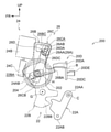
図1に示されるように、車両12における車両用ドアとしてのフロントドア14には、車両用ドアロック装置10が設けられている。フロントドア14は、車体16にヒンジ18を介して開閉可能に取り付けられている。この車両用ドアロック装置10は、フロントドア14における車両幅方向外側に設けられた図示しないドアアウタパネルと、車両幅方向内側に設けられたドアインナパネル14Aとによって区画される領域かつフロントドア14の車両後方側端部に設けられた後述するストライカ開口部14Bに対応した位置に配置されている。なお、フロントドア14は、車両幅方向にて左右一対に設けられており、それぞれのフロントドア14及び車両用ドアロック装置10は左右対称であるため、以下の説明では車両右側の車両用ドアロック装置10についてのみ説明する。
(overall structure)
As shown in FIG. 1, a vehicle
ドアアウタパネルには、操作部の一つとしてのドアアウタハンドル14Cが設けられている。このドアアウタハンドル14Cは、車両外方側へ向かって取り付けられており、一例として車両外部にいる図示しない操作者が把持してドアアウタパネルの面直方向へ向かって引く操作が可能とされている。
The door outer panel is provided with a door
ドアインナパネル14Aには、内装部材として車両幅方向内側からドアトリム14Dが取り付けられている。このドアトリム14Dにおける車両前方側には、ドアインナパネル14Aに取り付けられた操作部の一つとしてのドアインナハンドル14Eを露出させる図示しないインサイドレバー開口部が形成されており、これによって車両12の内部にいる図示しない乗員がドアインナハンドル14Eを操作可能とされている。ドアインナハンドル14Eは、一例として乗員が把持してドアインナパネル14Aの面直方向に向かって引く操作が可能とされている。
A door trim 14D is attached to the door
ドアインナパネル14Aの車両後方側端部には、ストライカ開口部14Bが形成されている。このストライカ開口部14Bは、車体16に設けられた図示しないストライカに対応した位置に形成されており、フロントドア14が閉状態時にドアインナパネル14Aの内部にストライカが挿入可能な形状に形成されている。
A
(ラッチ機構)
図2に示されるように、車両用ドアロック装置10は、図示しないユニットケース内にラッチ機構20と、機械的操作機構22と、電気的操作機構24とを有している。ラッチ機構20は、ラッチ20Aと、ラッチ保持ブラケット20Bと、解除部としてのポール20Cと、リフトレバー20Dとを有している。ラッチ20Aは、車両後方側から見た状態にてストライカ挿通溝20AAを内部に有する略U字状に形成されていると共に、締結具20ABによってラッチ20Aの車両前方側に設けられたラッチ保持ブラケット20Bの車両上方側に軸A中心にて回動可能に保持されている。なお、ラッチ20Aは、図示しないスプリングにより、ストライカ挿通溝20AAの開口が車両幅方向内側へ向くように(図3参照)付勢されている。この状態が請求項1に記載の「アンラッチ状態」に相当する。
(Latch mechanism)
As shown in FIG. 2, the vehicle
リフトレバー20Dは、ラッチ20Aに対して車両下方側に設けられていると共に、車両平面視にて略U字状に形成されている。具体的には、略車両前後方向に延設された第1側壁部20DAと、第1側壁部20DAに対して略車両幅方向外側に配置され略車両前後方向に延設された第2側壁部20DBと、第1側壁部20DAの車両後方側端部と第2側壁部20DBの車両後方側端部とを連結する連結壁部20DCとを含んで構成されている。連結壁部20DCは、締結具20DDによってラッチ保持ブラケット20Bの車両下方側に軸B中心にて回動可能に保持されている。なお、リフトレバー20Dは、図示しないスプリングにより、第1側壁部20DAを車両下方側へ押し下げる(第2側壁部20DBを車両上方側へ押し上げる)方向に付勢されている。
The
リフトレバー20Dの連結壁部20DCには、車両後方側へ突出された係合爪部20DEが形成されている(図4、図5参照)。この係合爪部20DEは、軸Bの連結壁部20DCに対して車両幅方向外側に形成されており、後述するポール20Cの係合孔部20CA内に係合されている。
An engaging claw portion 20DE projecting to the rear side of the vehicle is formed on the connecting wall portion 20DC of the
ポール20Cは、ラッチ20Aに対して車両下方側に設けられていると共に、略車両幅方向を長手方向とする略矩形状に形成されている。ポール20Cの長手方向一方側の端部20CBは、締結具20DDによってリフトレバー20Dと同様にラッチ保持ブラケット20Bの車両下方側に軸B中心にて回動可能に保持されている。また、ポール20Cの長手方向略中央部には、車両前後方向に貫通された係合孔部20CAが形成されている。この係合孔部20CAには、リフトレバー20Dの係合爪部20DEが係合されていることから、ポール20Cは、リフトレバー20Dと一体的に回動する。
The
ポール20Cの長手方向略中央における車両上方側には、ラッチ係合爪部20CCが形成されている。ラッチ係合爪部20CCは、ポール20Cから略車両上方側へ向けて突出された形状とされている。このラッチ係合爪部20CCは、リフトレバー20Dに外部からの入力がない状態(操作されていない状態)では、リフトレバー20Dの付勢力によってラッチ20Aの側面に当接する構成とされている。なお、ラッチ20Aがアンラッチ状態(図3参照)にてフロントドア14を閉めると、ラッチ20Aのストライカ挿通溝20AA内にストライカが挿入されることで、ストライカ挿通溝20AAの開口が車両幅方向外側へ向くようにラッチ20Aが回動される。この状態のラッチ20Aの側面に形成されたラッチ爪部20ADに、付勢力が作用することで第2側壁部20DBを車両上方側へ押し上げられたリフトレバー20Dのポール20Cのラッチ係合爪部20CCが係合される。これにより、ラッチ20Aの回動が制限されてフロントドア14の閉止状態が維持される。なお、この状態が請求項1に記載の「ラッチ状態」に相当する。
A latch engaging claw portion 20CC is formed on the upper side of the vehicle at substantially the center of the
(機械的操作機構)
機械的操作機構22は、インサイドレバー22Aと、アクティブレバー22Bと、オープンレバー22Cと、操作部の一つとしてのキーレバー22Dとを含んで構成されている。インサイドレバー22Aは、ラッチ機構20に対して車両下方側に設けられていると共に、車両上方側端部22AAが図示しない締結具により軸C中心にて回動可能に保持されている。インサイドレバー22Aの車両下方側端部22ABには、ドアインナハンドル14Eに連結されたワイヤケーブル14F(図1参照)が取り付けられている。したがって、インサイドレバー22Aは、ドアインナハンドル14Eの操作に伴って回動する。
(Mechanical operation mechanism)
The
オープンレバー22Cは、ラッチ機構20に対して車両下方側に設けられていると共に、図示しない締結具により軸D中心に回動可能に保持されている。そして、オープンレバー22Cの車両幅方向外側の端部22CAには、ドアアウタハンドル14C(図1参照)に連結されたロッド等(不図示)の連結部材が取り付けられている。また、オープンレバー22Cの車両幅方向内側の端部22CBには、リフトレバー20Dの第1側壁部20DA側に向かって突出された押し上げ部22CCが回動可能に取り付けられている。そして、オープンレバー22Cは、ドアアウタハンドル14Cをドアアウタパネルの面直方向へ向かって引く操作がされると、端部22CAを車両下方側へ押し下げるように回動する。これによって、端部22CBの押し上げ部22CCがリフトレバー20Dの第1側壁部20DA側を略車両上方側へ押し上げる。
The
アクティブレバー22Bは、インサイドレバー22Aに対して車両前方側に設けられていると共に、略車両上下方向に延設されており、ギヤ係合孔22BAと、レバー当接部22BBと、後述するキャンセル機構26の一部を構成する離脱部26Aとを有している。また、アクティブレバー22Bは、図示しない締結具により軸G中心にてロック位置(図示位置)とアンロック位置(図9参照)との間にて回動可能に保持されている。アクティブレバー22Bがロック位置にあると、ドアアウタハンドル14C及びドアインナハンドル14Eを操作しても、ラッチ20Aのラッチ状態からアンラッチ状態への移行が制限される。一方、アクティブレバー22Bがアンロック位置にあると、ドアアウタハンドル14C及びドアインナハンドル14Eを操作することで、ラッチ20Aをラッチ状態からアンラッチ状態へ移行させることができる。つまり、アクティブレバー22Bを回動させることで、フロントドア14のロックとアンロックを行うことができる。なお、アクティブレバー22Bにおけるフロントドア14のロック及びアンロックについては、一般的な車両用ドアロック装置と同様であり周知の技術のため、詳細な説明は省略する。
The
離脱部26Aは、アクティブレバー22Bの車両上方側に形成されていると共に、車両幅方向外側へ突出された解除爪26AAを有している。解除爪26AAは、車両後方側へ向かうに連れて車両下方側へ傾斜された傾斜面26ABを有しており、この傾斜面26ABの車両後方側端部は、後述するキャンセルレバー26Cがラッチ機構20をアンラッチ状態にする位置におけるリリース側係合孔部26BDの車両下方側面に対応した位置に配置されている(図5参照)。
The
レバー当接部22BBは、アクティブレバー22Bの車両下方側に形成されており、インサイドレバー22Aと対向するように形成されている。このレバー当接部22BBは、インサイドレバー22Aがドアインナハンドル14E(図1参照)の操作により車両下方側端部22ABが車両前方側(図5示時計回り方向)へ向かって回動した場合に、インサイドレバー22Aと当接する。これにより、レバー当接部22BBを軸G中心に車両前方側(図5示時計回り方向)へ向かって回動させて、アクティブレバー22Bをアンロック位置へと移動させる。つまり、アクティブレバー22Bは、インサイドレバー22Aと連動している。
The lever contact portion 22BB is formed on the lower side of the vehicle of the
ギヤ係合孔22BAは、離脱部26Aの車両下方側に形成されており、電気的操作機構24の一部を構成する後述するホイールギヤ24Aに形成されたギヤ突出部24AAが内部に挿通可能とされている。これにより、ホイールギヤ24Aを回転させることで、アクティブレバー22Bを軸G中心に回動させてロック位置又はアンロック位置へ移動させることができる。
The gear engagement hole 22BA is formed on the lower side of the vehicle of the
キーレバー22Dは、アクティブレバー22Bの車両上方側に配置されていると共に、連結レバー22DAを介してアクティブレバー22Bに連結されている。このキーレバー22Dは、ドアアウタパネルに設けられたキーシリンダにロッドを介して連結されている(いずれも不図示)。キーレバー22Dは、乗員が携帯する車両のイグニッションキー等の専用のキーにてキーシリンダを操作することで、連結レバー22DAを介してアクティブレバー22Bを軸G中心に回動させる。つまり、アクティブレバー22Bは、キーレバー22Dとも連動している。
The
(電気的操作機構)
電気的操作機構24は、駆動機構としての電動モータ24Bと、電動モータ24Bの出力軸に一体回転するよう取り付けられたウォームギヤ24Cと、ウォームギヤ24Cと噛合うホイールギヤ24Aとを有している。この電動モータ24Bは、CPUを備えるコントローラと電気的に接続されており、このコントローラと接続された開閉スイッチ等(いずれも不図示)の操作により作動可能とされている。
(Electrical operation mechanism)
The
ホイールギヤ24Aは、図示しない締結具により略車両幅方向を軸方向とする軸Hを中心に回動可能に保持されている。このホイールギヤ24Aの車両幅方向内側には、車両幅方向内側へ突出されたギヤ突出部24AAが形成されている。
The
(キャンセル機構)
キャンセル機構26は、レバー部材の一部としてのリリースレバー26Bと、レバー部材の他の一部としてのキャンセルレバー26Cと、キャンセルピン26Dと、離脱部26Aとを有している。リリースレバー26Bは、ホイールギヤ24Aの車両幅方向外側に配置されており、車両幅方向を板厚方向としかつ略車両上下方向を長手方向とする略矩形板状に形成されている。また、リリースレバー26Bは、車両下方側がホイールギヤ24Aを保持する図示しない締結具により保持されている。つまり、ホイールギヤ24Aと同一の軸Hを中心に回動可能とされている。
(Cancellation mechanism)
The cancel
リリースレバー26Bには、図4に示されるように、略車両後方側へ延出されかつホイールギヤ24Aの外周面上に折り返された押し上げ部26BAが形成されている。この押し上げ部26BAは、リフトレバー20Dの第1側壁部20DAの車両下方側に配置されている。したがって、図5に示されるように、リリースレバー26Bが図5示反時計回り方向に回動すると、リフトレバー20Dの第1側壁部20DAを押し上げてポール20Cとラッチ20Aとの係合を解除する(図3参照)。
As shown in FIG. 4, the
リリースレバー26Bの車両上方側には、板厚方向に貫通された第1貫通孔26BCが形成されている。この第1貫通孔26BCは、リリースレバー26Bの略短手方向を長手方向とする略矩形状に形成されていると共に、車両後方側かつ車両下方側の端部にリリース側係合孔部26BDが形成されている(図7参照)。このリリース側係合孔部26BDは、第1貫通孔26BCの下縁部に対して略車両下方側に切り欠くように形成されており、略車両前後方向(ホイールギヤ24Aの回動方向)の寸法が後述するキャンセルピン26Dのシャフト26DA(図5参照)の径寸法より若干大きい程度に設定されている。換言すると、第1貫通孔26BCとリリース側係合孔部26BDとの境界部は、リリース側係合孔部26BDの内部と外部とを連通する連通部26BGに相当する。また、第1貫通孔26BCの略車両前後方向(ホイールギヤ24Aの回動方向)の寸法は、キャンセルピン26Dが第1貫通孔26BCと後述するキャンセル側係合孔部26CCとに挿通された状態で押し上げ部26BAがリフトレバー20Dの第1側壁部20DAを押し上げない(ポール20Cがラッチ20Aと係合する)程度の大きさに設定されている(図8参照)。
A first through hole 26BC penetrated in the plate thickness direction is formed on the vehicle upper side of the
キャンセルレバー26Cは、リリースレバー26Bの車両幅方向外側に配置されており、リリースレバー26Bと同様に、車両幅方向を板厚方向としかつ略車両上下方向を長手方向とする略矩形板状に形成されている。キャンセルレバー26Cは、車両下方側がホイールギヤ24Aを保持する図示しない締結具により保持されている。つまり、キャンセルレバー26Cは、リリースレバー26Bと同様、ホイールギヤ24Aと同一の軸Hを中心に回動可能とされている。また、キャンセルレバー26Cとリリースレバー26Bとは、板厚方向にて重なるように配置されている。
The cancel
キャンセルレバー26Cの車両上方側には、板厚方向に貫通された第2貫通孔26CAが形成されている。この第2貫通孔26CAは、板厚方向視にて略円形状に形成されていると共に、キャンセルレバー26Cにおけるリリースレバー26Bの第1貫通孔26BCの車両上方側かつ車両後方側に対応した位置に設けられている。また、第2貫通孔26CAの車両下方側には、キャンセル側係合孔部26CCが形成されている(図7参照)。このキャンセル側係合孔部26CCは、第2貫通孔26CAの車両下方側の縁部からキャンセルレバー26Cにおけるリリースレバー26Bのリリース側係合孔部26BDに対応した位置まで切り欠くように形成されており(図5参照)、略車両前後方向(ホイールギヤ24Aの回動方向)の寸法はリリース側係合孔部26BDの略車両前後方向(ホイールギヤ24Aの回動方向)の寸法と略同一に設定されている。なお、第2貫通孔26CAは、車両側面視にてリリース側係合孔部26BDの連通部26BGよりも車両上方側に配置されている。したがって、キャンセル側係合孔部26CCは、連通部26BGに対応した位置を含んで形成されている。
A second through hole 26CA penetrating in the plate thickness direction is formed on the vehicle upper side of the cancel
キャンセルレバー26Cの車両下方側には、ギヤ係合部26CBが形成されている。ギヤ係合部26CBは、ホイールギヤ24A等を保持する締結具に対して車両下方側に形成されており、車両幅方向内側へ向けて屈曲されている。そして、ギヤ係合部26CBの車両前方側は、ギヤ係合部26CBに対して略車両前方側かつホイールギヤ24Aの車両幅方向外側面に形成されている突起部24ABに係合可能とされている。
A gear engaging portion 26CB is formed on the vehicle lower side of the cancel
キャンセルピン26Dは、リリース側係合孔部26BDとキャンセル側係合孔部26CCとに挿入されている。このキャンセルピン26Dは、略車両幅方向を軸方向とする円柱状のシャフト26DA(図5参照)と、シャフト26DAの車両幅方向外側の端部に設けられた第1ワッシャ26DBと、シャフト26DAの車両幅方向内側の端部に設けられた第2ワッシャ26DC(図3参照)とを有している。第1ワッシャ26DBは、径寸法がキャンセルレバー26Cのキャンセル側係合孔部26CC(図7参照)の略車両前後方向の寸法より大きく設定されている。
The cancel
図3に示されるように、第2ワッシャ26DCは、リリースレバー26Bのリリース側係合孔部26BD(図7参照)の略車両前後方向の寸法よりも大きく設定されている。上述した構成により、キャンセルレバー26Cとリリースレバー26Bとは、ホイールギヤ24Aと連動して軸Hを中心に一体的に回動可能とされている。
As shown in FIG. 3, the second washer 26DC is set to be larger than the dimension of the release side engaging hole portion 26BD (see FIG. 7) of the
(中立状態)
フロントドア14が閉状態とされた状態では、図2に示されるように、ラッチ20Aのストライカ挿通溝20AA内に図示しないストライカのシャフトが挿通された状態でストライカ挿通溝20AAの開口を略車両幅方向外側に向けた状態(ラッチ状態)とされている。この状態のラッチ20Aには、リフトレバー20Dに取り付けられたポール20Cのラッチ係合爪部20CCがラッチ爪部20ADと係合されている。これにより、フロントドア14の閉状態が維持される。なお、この状態を以下、「中立状態」と称する。
(Neutral state)
When the
(電気的操作機構の作動について)
中立状態からフロントドア14を開状態にするための図示しない開閉スイッチの操作を行うと、この開閉スイッチに電気的に接続されたコントローラにより電気的操作機構24の電動モータ24Bが回転して、ウォームギヤ24Cを介してホイールギヤ24Aを図5示反時計回り方向に回動させる。これにより、図5に示されるように、突起部24ABがキャンセルレバー26Cのギヤ係合部26CBに当接してキャンセルレバー26Cを軸H中心にて図5示反時計回り方向に回転させる。したがって、キャンセルピン26Dによりキャンセルレバー26Cと連結されたリリースレバー26Bも軸H中心にて図5示反時計回り方向に回転するため、図3、図4に示されるように、リリースレバー26Bの押し上げ部26BAがリフトレバー20Dの第1側壁部20DAをリフトレバー20Dの付勢力に抗して押し上げる。したがって、リフトレバー20Dと一体的に回動するポール20Cがラッチ20Aと離れる方向に移動するため、ラッチ係合爪部20CCとラッチ爪部20ADとの係合が解除される。これにより、ラッチ20Aは付勢力によりストライカ挿通溝20AAの開口が車両幅方向内側へ向くように回動する(アンラッチ状態)。これにより、フロントドア14が開状態となる。
(About the operation of the electrical operation mechanism)
When an open / close switch (not shown) for opening the
一方、上述した状態にて電動モータ24Bを反対側に回転させてウォームギヤ24Cを介してホイールギヤ24Aを図5示時計回り方向に回動させると、リリースレバー26Bの押し上げ部26BAがリフトレバー20Dの第1側壁部20DAをリフトレバー20Dの付勢力に抗して押し上げる力が低下する。つまり、押し上げ部26BAがリフトレバー20Dの付勢力によって押し下げられる。したがって、リフトレバー20Dと一体的に回動するポール20Cがラッチ20Aと近づく方向に移動する。この状態にてフロントドア14を閉止してラッチ20Aをストライカ挿通溝20AAの開口が車両幅方向外側へ向くように回動させると、ラッチ係合爪部20CCがラッチ爪部20ADに係合される(ラッチ状態)。これにより、フロントドア14閉状態となりかつこの閉状態が維持される。
On the other hand, when the
(機械的操作機構の作動について)
一方、図2に示される中立状態からドアアウタハンドル14C及びドアインナハンドル14E(図1参照)を操作した場合の作動については、一般的な車両用ドアロック装置と同様であり周知の技術のため、詳細な説明は省略する。
(About the operation of the mechanical operation mechanism)
On the other hand, the operation when the door
(キャンセル機構の作動について)
図3に示されるように、電気的操作機構24によりリフトレバー20Dの第1側壁部20DAが押し上げられた状態、すなわち、ラッチ機構20がアンラッチ状態となってフロントドア14が開状態となった状態で、ドアインナハンドル14E(図1参照)を操作すると、図5に示されるインサイドレバー22Aが軸C中心に図5示時計回り方向にて回動する。これに伴って、アクティブレバー22Bも軸G中心に図5示時計回り方向にて回動する(図中二点鎖線から実線へ回動)。そして、アクティブレバー22Bの離脱部26Aがキャンセルピン26Dへ向かって移動して、傾斜面26ABがキャンセルピン26Dを略車両上方側へと押し上げる(図6参照)。これにより、キャンセルピン26Dは、リリース側係合孔部26BDから第1貫通孔26BCへと移動(リリース側係合孔部26BDとの係合が解除)される(図8参照)。このため、リリースレバー26Bとキャンセルレバー26Cとの連結が解除され、図7に示されるように、リリースレバー26Bの押し上げ部26BAはリフトレバー20Dの付勢力によって車両下方側へ押し下げられる。つまり、リリースレバー26Bは、図7示時計回り方向に回動する。これにより、リフトレバー20Dに取り付けられたポール20Cのラッチ係合爪部20CCが、ラッチ20Aのラッチ爪部20ADに近づく方向に移動する。この状態にてフロントドア14を閉止してラッチ20Aをストライカ挿通溝20AAの開口が車両幅方向外側へ向くように回動させると、ラッチ係合爪部20CCがラッチ爪部20ADに係合される(ラッチ状態、図2参照)。これにより、フロントドア14閉状態となりかつこの閉状態が維持される。なお、上述のように、アクティブレバー22Bはキーレバー22Dとも連動している。したがって、キーシリンダを介してキーレバー22Dを回動させても、アクティブレバー22Bの離脱部26Aはドアインナハンドル14Eによる操作と同様に作動可能とされている。
(About the operation of the cancel mechanism)
As shown in FIG. 3, a state in which the first side wall portion 20DA of the
また、図9に示されるように、リリースレバー26Bの押し上げ部26BAがリフトレバー20Dの第1側壁部20DAを押し上げていない状態(ラッチ状態)にてアクティブレバー22Bをロック状態となるように図9示時計回り方向に回動させても、アクティブレバー22Bの離脱部26Aがキャンセルピン26Dに当接しないように離脱部26A、キャンセルピン26D、リリース側係合孔部26BD及びキャンセル側係合孔部26CCの位置が設定されている。
Further, as shown in FIG. 9, the
(第1実施形態の作用・効果) (Action / effect of the first embodiment)
ここで、図10、図11に示される対比例を用いながら、本実施形態の作用並びに効果を説明することにする。なお、本実施形態と同一構成部分については同一番号を付してその説明を省略する。 Here, the actions and effects of the present embodiment will be described with reference to the inverse proportions shown in FIGS. 10 and 11. The same components as those in the present embodiment are designated by the same numbers, and the description thereof will be omitted.
図10に示されるように、ホイールギヤ24Aの車両幅方向外側にレバー部材100が設けられている。このレバー部材100は、車両幅方向を板厚方向としかつホイールギヤ24Aを保持する図示しない締結具により保持されている。つまり、ホイールギヤ24Aと同一の軸Hを中心に回動可能とされている。
As shown in FIG. 10, a
レバー部材100には、ギヤ係合部100Aが形成されている。このギヤ係合部100Aは、ホイールギヤ24Aの突起部24ABに車両前方側が係合可能とされている。つまり、ホイールギヤ24Aが図10示反時計回転方向に回動すると、レバー部材100はホイールギヤ24Aと一体的に回動する。
A
レバー部材100には、略車両後方側へ延出されかつホイールギヤ24Aの外周面上に折り返された押し上げ部100Bが形成されている。この押し上げ部100Bは、リフトレバー20Dの第1側壁部20DAの車両下方側に配置されている。したがって、図11に示されるように、電気的操作機構24の作動によりホイールギヤ24Aが回動することで、レバー部材100が図11示反時計回り方向に回動すると、リフトレバー20Dの第1側壁部20DAを押し上げてポール20Cとラッチ20Aとの係合を解除する(図3参照)。
The
しかしながら、レバー部材100がリフトレバー20Dの第1側壁部20DAを押し上げた状態で電気的操作機構24が故障した場合、ポール20Cとラッチ20Aとの係合が解除されたままの状態になる。つまり、ラッチ20Aの回動を止めることができず、アンラッチ状態のままになるため、フロントドア14(図1参照)を開状態から閉状態にしても、閉状態を維持できないため意図せずに開状態となる。したがって、車両を走行させることができない可能性がある。
However, if the
これに対し、本実施形態では、図2に示されるように、車両用ドアロック装置10は、ラッチ機構20と、機械的操作機構22と、電気的操作機構24と、を有している。ラッチ機構20は、フロントドア14に設けられていると共に、車体16に対してフロントドア14を開放可能にするアンラッチ状態と、車体16に対してフロントドア14を閉止した状態を維持するラッチ状態とを選択的にとる。このラッチ機構20は、アンラッチ状態にて車体16に対してフロントドア14を閉止するとアンラッチ状態からラッチ状態へ移行する。また、機械的操作機構22は、ドアアウタハンドル14C又はドアインナハンドル14Eが操作されることによりラッチ機構20をラッチ状態からアンラッチ状態へ切り替える。一方、電気的操作機構24は、電動モータ24Bが連結されかつこの電動モータ24Bの動力によりラッチ機構20をラッチ状態又はアンラッチ状態へ切り替える。したがって、電気的操作機構24により、乗員はフロントドア14を開状態及び閉状態にする際の操作力を低減することができる。
On the other hand, in the present embodiment, as shown in FIG. 2, the vehicle
ここで、車両用ドアロック装置10は、キャンセル機構26を有しており、このキャンセル機構26は、電気的操作機構24と機械的操作機構22との連結を解除することができる。したがって、電気的操作機構24が故障した場合、キャンセル機構26により電気的操作機構24と機械的操作機構22との連結を解除することで、ラッチ機構20が電気的操作機構24によってアンラッチ状態のままになるのを防ぐことができる。これにより、電気的操作機構24と切り離されたラッチ機構20は、フロントドア14を閉止するとアンラッチ状態からラッチ状態へと移行する。つまり、電気的操作機構24が故障した場合でもフロントドア14を閉状態にて維持することができる。
Here, the vehicle
また、キャンセル機構26は、ドアインナハンドル14E又はキーレバー22Dにより操作可能とされている。つまり、機械的操作機構22を操作するドアインナハンドル14E又はキーレバー22Dをキャンセル機構26の操作に兼用させることができるので、部品点数を削減することができる。
Further, the cancel
さらに、ラッチ機構20は、ポール20Cを有している。このポール20Cは、ラッチ20Aに係合する係合状態と、ラッチ20Aに係合しない非係合状態とを選択的にとる。また、電気的操作機構24は、ホイールギヤ24Aと、リリースレバー26Bと、キャンセルレバー26Cと、キャンセルピン26Dとを有している。ホイールギヤ24Aは、電動モータ24Bに係合されていると共に回動可能とされている。リリースレバー26Bと、キャンセルレバー26Cと、キャンセルピン26Dとは、一体的に構成されかつ一部がホイールギヤ24Aに係合されており、ホイールギヤ24Aの回動に連動して変位することでポール20Cの係合状態と非係合状態とを切り替え可能とされている。したがって、電動モータ24Bを作動させることで、ラッチ機構20のラッチ状態とアンラッチ状態とを切り替えることができる。つまり、上述した簡易な構成によって、電動モータ24Bからの駆動力を用いてラッチ機構20の操作を行うことができる。
Further, the
さらにまた、リリースレバー26Bと、キャンセルレバー26Cと、キャンセルピン26Dとは、ホイールギヤ24Aに係合されたキャンセルレバー26Cと、ポール20Cの状態を切り替えると共にキャンセルレバー26Cのリリース側係合孔部26BDに対応する位置にてキャンセル側係合孔部26CCが形成されたリリースレバー26Bと、キャンセルピン26Dとを有している。キャンセルピン26Dは、リリース側係合孔部26BDとキャンセル側係合孔部26CCとにそれぞれ係合するように挿入されている。したがって、キャンセルレバー26Cとリリースレバー26Bとは、いわばキャンセルピン26Dにより連結されていることから、ホイールギヤ24Aの回動に連動してキャンセルレバー26Cとリリースレバー26Bとを変位させてポール20Cの係合状態と非係合状態とを切り替えることができる。つまり、電動モータ24Bからの駆動力を用いてラッチ機構20の操作を行うことができる。
Furthermore, the
ここで、キャンセル機構26は、離脱部26Aを有しており、この離脱部26Aは、キャンセルピン26Dにおけるリリース側係合孔部26BDとの係合を解除させる。これにより、キャンセルレバー26Cとリリースレバー26Bとの連結が解除されてキャンセルレバー26Cとリリースレバー26Bとが互いに相対移動可能となることから、電動モータ24Bが故障しても、リリースレバー26Bを移動させてポール20Cの係合状態と非係合状態とを切り替えて、ラッチ機構20のラッチ状態とアンラッチ状態とを切り替えることができる。つまり、上述した簡易な構成によって、ラッチ機構20が閉状態や開状態にて保持されるのを解除できる。
Here, the cancel
また、キャンセル機構26の離脱部26Aは、アクティブレバー22Bに設けられている。このアクティブレバー22Bは、機械的操作機構22の一部を構成しかつドアインナハンドル14E又はキーレバー22Dの操作によりポール20Cの係合状態から非係合状態への移行を制限するロック状態と、ポール20Cの係合状態から非係合状態への移行を許可するアンロック状態とを切り替える。つまり、機械的操作機構22を操作するドアインナハンドル14E又はキーレバー22Dをキャンセル機構26の操作に兼用させることができる。したがって、部品点数を削減することができる。これらにより、コストを低減することができる。
Further, the
さらに、アクティブレバー22Bは、フロントドア14の車両幅方向外側に設けられるキーレバー22Dと、フロントドア14の車両幅方向内側に設けられるインサイドレバー22Aとが連結されている。そして、キーレバー22Dは、ドアアウタパネルに設けられたキーシリンダを介して操作可能とされている。また、インサイドレバー22Aは、ドアインナハンドル14E(図1参照)を介して操作可能とされている。これらの操作により、アクティブレバー22Bの離脱部26Aを操作可能とされている。したがって、乗員は、従来のフロントドア14の開閉操作によりキャンセル機構26も操作することができる。つまり、キャンセル機構26の操作を容易に行うことができる。
Further, the
さらにまた、リリース側係合孔部26BDには、外縁部の一部に外部と内部とを連通する連通部26BGが形成されている。したがって、リリース側係合孔部26BD内に挿入されたキャンセルピン26Dは、連通部26BGから外部へ移動させることでキャンセルピン26Dのリリース側係合孔部26BDへの係合を解除することができる。一方、キャンセル側係合孔部26CCは、連通部26BGに対応した位置にてキャンセルピン26Dと係合していることから、キャンセルピン26Dのリリース側係合孔部26BDへの係合が解除された状態でも、キャンセルピン26Dはキャンセル側係合孔部26CCに係合している。したがって、キャンセルピン26Dがキャンセル側係合孔部26CCに残った状態となるため、キャンセル機構26を作動させた後にキャンセルピン26Dを再度リリース側係合孔部26BDに挿入させる作業が容易となる。これにより、メンテナンス性を向上させることができる。
Furthermore, in the release-side engaging hole portion 26BD, a communication portion 26BG that communicates the outside and the inside is formed in a part of the outer edge portion. Therefore, the cancel
(第2実施形態)
次に、図12~図13を用いて、本発明の第2実施形態に係る車両用ドアロック装置200について説明する。なお、前述した第1実施形態等と同一構成部分については、同一番号を付してその説明を省略する。
(Second Embodiment)
Next, the vehicle
この第2実施形態に係る車両用ドアロック装置200は、基本的な構成は第1実施形態と同様とされ、中立状態復帰スプリング202が設けられている点に特徴がある。
The vehicle
すなわち、図12に示されるように、電気的操作機構24に設けられたホイールギヤ204は、図示しない締結具により略車両幅方向を軸方向とする軸Hを中心に回動可能に保持されている。このホイールギヤ204を保持する締結具には、中立状態復帰スプリング202が取り付けられている。中立状態復帰スプリング202は、軸Hを中心にホイールギヤ204を図12示時計回転方向へ回転するように付勢している。したがって、電動モータ24Bを作動させてラッチ機構20をラッチ状態からアンラッチ状態へ切り替える場合は、図13に示されるように、ホイールギヤ204が図13示反時計回転方向にて中立状態復帰スプリング202の付勢力に抗しながら回転するように電動モータ24Bを回転させる。これにより、ホイールギヤ204と一体的に回動するキャンセルレバー26C及びリリースレバー26Bも図13示反時計回転方向に回転するため、リリースレバー26Bの押し上げ部26BAがリフトレバー20Dの第1側壁部20DAをリフトレバー20Dの付勢力に抗して押し上げる。したがって、リフトレバー20Dと一体的に回動するポール20Cがラッチ20Aと離れる方向に移動するため、ラッチ係合爪部20CCとラッチ爪部20ADとの係合が解除される(図3参照)。
That is, as shown in FIG. 12, the
ここで、電気的操作機構24に電気的故障が発生した場合、すなわち、電動モータ24Bが開閉スイッチの操作により作動しない場合かつウォームギヤ24Cやホイールギヤ204自体は回転可能とされている場合は、図12に示されるように、中立状態復帰スプリング202の付勢力によりホイールギヤ204が図12示時計回転方向に回転する。これにより、ホイールギヤ204と一体的に回動するキャンセルレバー26C及びリリースレバー26Bも図12示時計回転方向に回転して、リリースレバー26Bの押し上げ部26BAがリフトレバー20Dの第1側壁部20DAに対して車両下方側へ離間する。そして、リフトレバー20Dに取り付けられたポール20Cのラッチ係合爪部20CCが、ラッチ20Aのラッチ爪部20ADに近づいて当該ラッチ爪部20ADと係合可能とされる(図2参照)。つまり、ラッチ20Aをラッチ状態に維持できるので、フロントドア14の閉状態を維持することができる。なお、上述した電気的操作機構24の「電気的故障」には、コントローラや開閉スイッチの故障により、ウォームギヤ24Cやホイールギヤ204自体は回転可能とされているが電動モータ24Bが作動しない場合等も含まれる。これに対し、ウォームギヤ24Cとホイールギヤ204との間に異物が入り込んでウォームギヤ24Cやホイールギヤ204の歯が破損するなど、ウォームギヤ24Cやホイールギヤ204が回転しない(ロックした)状態を以下の説明では「機械的故障」と称する。この機械的故障の場合では、キャンセル機構26を作動させることにより、第1実施形態と同様にフロントドア14の閉状態を維持することができる。
Here, when an electric failure occurs in the
(第2実施形態の作用・効果)
次に、第2実施形態の作用並びに効果を説明する。
(Action / effect of the second embodiment)
Next, the operation and effect of the second embodiment will be described.
上記構成によっても、中立状態復帰スプリング202が設けられている点以外は第1実施形態の車両用ドアロック装置10と同様に構成されているので、第1実施形態と同様の効果が得られる。また、中立状態復帰スプリング202が設けられていることで、電気的操作機構24が電気的故障の場合は、キャンセル機構26を作動させてリリースレバー26Bとキャンセルレバー26Cとの連結を解除しなくても、ラッチ20Aをアンラッチ状態からラッチ状態へ切り替えることができるため、フロントドア14を開状態から閉状態にすることができる。したがって、電気的故障の場合は、修理時に電気的操作機構24のみを修理すればよく、キャンセルピン26Dを再度設定し直す手間が不要となる。これにより、修理メンテナンス性を向上させることができる。
Even with the above configuration, since it is configured in the same manner as the vehicle
なお、上述した第1、第2実施形態では、離脱部26Aがキャンセルピン26Dにおけるリリース側係合孔部26BDとの係合を解除する構成とされているが、これに限らず、キャンセル側係合孔部26CCとの係合を解除する構成としてもよいし、その両方でもよい。また、離脱部26Aがキャンセルピン26Dを略車両上方側へと押し上げることでリリースレバー26Bとキャンセルレバー26Cとの連結が解除される構成とされているが、これに限らず、一例としてキャンセルピン26Dをリリースレバー26Bとキャンセルレバー26Cとの間にて切断してリリースレバー26Bとキャンセルレバー26Cとの連結を解除する構成としてもよいし、その他の構成としてもよい。
In the first and second embodiments described above, the
さらに、アクティブレバー22Bは、ドアインナハンドル14E又はキーレバー22Dの操作により離脱部26Aが操作される構成とされているが、これに限らず、ドアアウタハンドル14Cの操作により離脱部26Aが操作される構成としてもよいし、ドアインナハンドル14E又はキーレバー22Dどちらか一方のみの操作により離脱部26Aが操作される構成としてもよい。また、これ以外の操作部により離脱部26Aが操作される構成としてもよい。
Further, the
さらにまた、車両用ドアロック装置10、200は、フロントドア14に設けられた構成とされているが、これに限らず、リヤドアやテールゲートドア等その他のドアに設けられた構成としてもよい。
Furthermore, the vehicle
また、リリース側係合孔部26BDには、外縁部の一部に外部と内部とを連通する連通部26BG(図7参照)が形成されており、キャンセル側係合孔部26CCは、連通部26BGに対応した位置にてキャンセルピン26Dと係合している構成とされているが、これに限らず、リリース側係合孔部26BDとキャンセルピン26Dとを入れ替えた構成としてもよい。すなわち、キャンセル側係合孔部26CCに連通部を設けて、リリース側係合孔部26BDはこの連通部に対応した位置にてキャンセルピン26Dと係合する構成としてもよい。
Further, in the release side engaging hole portion 26BD, a communication portion 26BG (see FIG. 7) that communicates the outside and the inside is formed in a part of the outer edge portion, and the cancel side engaging hole portion 26CC is a communication portion. The configuration is such that the cancel
以上本発明は、上記の形態例に限定されるものではなく、上記の形態例以外にも、その主旨を逸脱しない範囲内において種々変形して実施可能であることは勿論である。 As described above, the present invention is not limited to the above-mentioned embodiment, and it is needless to say that the present invention can be variously modified and implemented within a range not deviating from the gist thereof other than the above-mentioned embodiment.
10 車両用ドアロック装置
14 フロントドア(車両用ドア)
14Cドアアウタハンドル(操作部)
14Eドアインナハンドル(操作部)
16 車体
20 ラッチ機構
20A ラッチ
20C ポール(解除部)
22 機械的操作機構
22A インサイドレバー
22B アクティブレバー
22D キーレバー(操作部)
24 電気的操作機構
24A ホイールギヤ
24B 電動モータ(駆動機構)
26 キャンセル機構
26A 離脱部
26B リリースレバー
26BD リリース側係合孔部
26BG 連通部
26C キャンセルレバー
26CC キャンセル側係合孔部
26D キャンセルピン
200 車両用ドアロック装置
10 Vehicle
14C door outer handle (operation part)
14E Door Inner Handle (Operation Unit)
16
22
24
26 Cancel
Claims (6)
複数設けられた操作部のうち少なくとも一つの当該操作部が操作されることにより前記ラッチ機構を前記ラッチ状態から前記アンラッチ状態へ切り替える機械的操作機構と、
前記機械的操作機構に連結されていると共に、駆動機構を備えておりかつ当該駆動機構を作動させることで当該駆動機構の動力により前記ラッチ機構を前記ラッチ状態又は前記アンラッチ状態へ切り替える電気的操作機構と、
前記電気的操作機構と前記機械的操作機構との連結を解除するキャンセル機構と、
を備え、
前記ラッチ機構は、ラッチに係合する係合状態と、当該ラッチに係合しない非係合状態とを選択的にとる解除部を有しており、
前記電気的操作機構は、前記駆動機構に係合されていると共に回動可能とされたホイールギヤと、前記ホイールギヤに係合されていると共に前記ホイールギヤの回動に連動して変位することで前記解除部の係合状態と非係合状態とを切り替えるレバー部材と、を有している車両用ドアロック装置。 It is provided on the vehicle door and selectively takes an unlatch state that allows the vehicle door to be opened to the vehicle body and a latch state that maintains the vehicle door closed to the vehicle body. A latch mechanism that shifts from the unlatch state to the latch state when the vehicle door is closed with respect to the vehicle body in the unlatch state.
A mechanical operation mechanism that switches the latch mechanism from the latch state to the unlatch state by operating at least one of the plurality of operation units provided.
An electrical operation mechanism that is connected to the mechanical operation mechanism, has a drive mechanism, and switches the latch mechanism to the latch state or the unlatch state by the power of the drive mechanism by operating the drive mechanism. When,
A canceling mechanism that disengages the connection between the electrical operating mechanism and the mechanical operating mechanism, and
Equipped with
The latch mechanism has a release portion that selectively takes an engaged state that engages with the latch and a non-engaged state that does not engage with the latch.
The electrically operating mechanism displaces the wheel gear that is engaged with the drive mechanism and is rotatable, and the wheel gear that is engaged with the wheel gear and is displaced in conjunction with the rotation of the wheel gear. A vehicle door lock device comprising a lever member for switching between an engaged state and a non-engaged state of the disengaged portion .
請求項1記載の車両用ドアロック装置。 The cancel mechanism can be operated by at least one of the plurality of operation units.
The vehicle door lock device according to claim 1.
前記ホイールギヤに係合されると共にキャンセル側係合孔部が形成されたキャンセルレバーと、
前記解除部の状態を切り替えると共に、前記キャンセルレバーの前記キャンセル側係合孔部に対応する位置にてリリース側係合孔部が形成されたリリースレバーと、
前記キャンセル側係合孔部と前記リリース側係合孔部とにそれぞれ係合するように挿入されたキャンセルピンとを有しており、
前記キャンセル機構には、前記キャンセルピンにおける前記キャンセル側係合孔部及び前記リリース側係合孔部の少なくとも一方との係合を解除させる離脱部が設けられている、
請求項1又は請求項2記載の車両用ドアロック装置。 The lever member is
A cancel lever that is engaged with the wheel gear and has an engaging hole on the canceling side.
A release lever in which the state of the release portion is switched and a release side engagement hole portion is formed at a position corresponding to the cancellation side engagement hole portion of the cancel lever.
It has a cancel pin inserted so as to engage with the cancel side engagement hole portion and the release side engagement hole portion, respectively.
The canceling mechanism is provided with a disengagement portion for disengaging the canceling pin from engaging with at least one of the canceling side engaging hole portion and the release side engaging hole portion.
The vehicle door lock device according to claim 1 or 2 .
請求項3記載の車両用ドアロック装置。 The cancel mechanism constitutes a part of the mechanical operation mechanism and limits the transition from the engaged state to the non-engaged state of the disengaged portion by the operation of at least one of the operating portions. The disengagement portion is provided in the active lever that switches between the locked state and the unlocked state that permits the transition from the engaged state to the non-engaged state of the disengaging portion.
The vehicle door lock device according to claim 3 .
請求項4記載の車両用ドアロック装置。 The active lever is interlocked with at least one of a key lever provided on the outside of the vehicle door in the vehicle width direction and an inside lever provided on the inside of the vehicle door in the vehicle width direction, and the operation of the key lever or the inside lever. The disengagement portion can be operated so that the cancel pin is disengaged from at least one of the cancel side engaging hole portion and the release side engaging hole portion.
The vehicle door lock device according to claim 4 .
前記キャンセル側係合孔部は、前記連通部に対応した位置にて前記キャンセルピンと係合している、
請求項3~請求項5のいずれか一項に記載の車両用ドアロック装置。 In the release-side engaging hole portion, a communication portion for communicating the outside and the inside is formed in a part of the outer edge portion.
The canceling side engaging hole portion is engaged with the canceling pin at a position corresponding to the communicating portion.
The vehicle door lock device according to any one of claims 3 to 5 .
Priority Applications (4)
| Application Number | Priority Date | Filing Date | Title |
|---|---|---|---|
| JP2018063027A JP7035709B2 (en) | 2018-03-28 | 2018-03-28 | Vehicle door lock device |
| US16/259,557 US11293205B2 (en) | 2018-03-28 | 2019-01-28 | Vehicle door lock device |
| CN201910100881.7A CN110318609A (en) | 2018-03-28 | 2019-01-31 | Door lock device for vehicle |
| DE102019106121.0A DE102019106121A1 (en) | 2018-03-28 | 2019-03-11 | Fahrzeugtürarretiervorrichtung |
Applications Claiming Priority (1)
| Application Number | Priority Date | Filing Date | Title |
|---|---|---|---|
| JP2018063027A JP7035709B2 (en) | 2018-03-28 | 2018-03-28 | Vehicle door lock device |
Publications (3)
| Publication Number | Publication Date |
|---|---|
| JP2019173401A JP2019173401A (en) | 2019-10-10 |
| JP2019173401A5 JP2019173401A5 (en) | 2021-02-12 |
| JP7035709B2 true JP7035709B2 (en) | 2022-03-15 |
Family
ID=67909812
Family Applications (1)
| Application Number | Title | Priority Date | Filing Date |
|---|---|---|---|
| JP2018063027A Active JP7035709B2 (en) | 2018-03-28 | 2018-03-28 | Vehicle door lock device |
Country Status (4)
| Country | Link |
|---|---|
| US (1) | US11293205B2 (en) |
| JP (1) | JP7035709B2 (en) |
| CN (1) | CN110318609A (en) |
| DE (1) | DE102019106121A1 (en) |
Families Citing this family (1)
| Publication number | Priority date | Publication date | Assignee | Title |
|---|---|---|---|---|
| KR20200101073A (en) * | 2019-02-19 | 2020-08-27 | 현대자동차주식회사 | Motor-driven door latch for vehicle |
Citations (4)
| Publication number | Priority date | Publication date | Assignee | Title |
|---|---|---|---|---|
| US20040201226A1 (en) | 2003-03-22 | 2004-10-14 | Spurr Nigel Victor | Power operable latch that relatches in the event of motor failure |
| JP2014009588A (en) | 2012-06-29 | 2014-01-20 | Aisin Seiki Co Ltd | Vehicle door opening/closing device |
| CN203476012U (en) | 2012-09-13 | 2014-03-12 | 三井金属爱科特株式会社 | Latch system used for vehicle |
| JP2016102324A (en) | 2014-11-28 | 2016-06-02 | アイシン精機株式会社 | Vehicle door operation device |
Family Cites Families (16)
| Publication number | Priority date | Publication date | Assignee | Title |
|---|---|---|---|---|
| US5715713A (en) * | 1996-01-11 | 1998-02-10 | General Motors Corporation | Door latch locking actuator assembly |
| DE10065569B4 (en) * | 1999-12-28 | 2007-12-20 | Ohi Seisakusho Co., Ltd., Yokohama | Device for opening and closing motor vehicle locks |
| EP1245764B1 (en) | 2001-03-28 | 2007-05-30 | Aisin Seiki Kabushiki Kaisha | Door latch operation device for vehicle |
| JP4617588B2 (en) | 2001-03-28 | 2011-01-26 | アイシン精機株式会社 | Vehicle door latch operating device |
| JP2004250899A (en) | 2003-02-18 | 2004-09-09 | Aisin Seiki Co Ltd | Drive canceling mechanism |
| JP2006233456A (en) * | 2005-02-22 | 2006-09-07 | Aisin Seiki Co Ltd | Door lock device |
| JP4618318B2 (en) * | 2008-04-18 | 2011-01-26 | アイシン精機株式会社 | Vehicle door lock device |
| JP5102137B2 (en) * | 2008-07-30 | 2012-12-19 | アイシン機工株式会社 | Vehicle door latch device |
| CA2697768A1 (en) * | 2009-03-25 | 2010-09-25 | Magna Closures Inc. | Closure latch for vehicle door |
| JP2010281110A (en) * | 2009-06-04 | 2010-12-16 | Tokai Rika Co Ltd | Key lock device |
| JP4963720B2 (en) * | 2009-12-21 | 2012-06-27 | 三井金属アクト株式会社 | Actuator in vehicle door latch device |
| JP5447860B2 (en) * | 2010-03-24 | 2014-03-19 | アイシン精機株式会社 | Vehicle door lock device |
| GB2518082A (en) * | 2012-05-16 | 2015-03-11 | Magna Closures Inc | Door latch with double lock |
| GB2505745B (en) * | 2012-06-28 | 2015-08-12 | Mitsui Kinzoku Act Corp | Vehicle door closer device |
| WO2014102283A2 (en) | 2012-12-24 | 2014-07-03 | Magna Closures S.P.A. | Backup energy source for automotive systems and related control method |
| JP6471600B2 (en) | 2015-04-23 | 2019-02-20 | アイシン精機株式会社 | Vehicle door lock device |
-
2018
- 2018-03-28 JP JP2018063027A patent/JP7035709B2/en active Active
-
2019
- 2019-01-28 US US16/259,557 patent/US11293205B2/en active Active
- 2019-01-31 CN CN201910100881.7A patent/CN110318609A/en active Pending
- 2019-03-11 DE DE102019106121.0A patent/DE102019106121A1/en active Pending
Patent Citations (5)
| Publication number | Priority date | Publication date | Assignee | Title |
|---|---|---|---|---|
| US20040201226A1 (en) | 2003-03-22 | 2004-10-14 | Spurr Nigel Victor | Power operable latch that relatches in the event of motor failure |
| JP2014009588A (en) | 2012-06-29 | 2014-01-20 | Aisin Seiki Co Ltd | Vehicle door opening/closing device |
| CN203476012U (en) | 2012-09-13 | 2014-03-12 | 三井金属爱科特株式会社 | Latch system used for vehicle |
| JP2014074324A (en) | 2012-09-13 | 2014-04-24 | Mitsui Kinzoku Act Corp | Door latch system for vehicle |
| JP2016102324A (en) | 2014-11-28 | 2016-06-02 | アイシン精機株式会社 | Vehicle door operation device |
Also Published As
| Publication number | Publication date |
|---|---|
| US20190301211A1 (en) | 2019-10-03 |
| DE102019106121A1 (en) | 2019-10-02 |
| US11293205B2 (en) | 2022-04-05 |
| CN110318609A (en) | 2019-10-11 |
| JP2019173401A (en) | 2019-10-10 |
Similar Documents
| Publication | Publication Date | Title |
|---|---|---|
| US20210355719A1 (en) | Closure latch assembly with a power release mechanism and an inside handle release mechanism | |
| JP4659602B2 (en) | Control device for vehicle door latch | |
| CN107829623B (en) | Locking device and method for vehicle door | |
| WO2016084805A1 (en) | Vehicle door operating device | |
| JPH09511290A (en) | Vehicle door lock actuator | |
| JP6704906B2 (en) | Door latch device for automobile | |
| US20180195315A1 (en) | Freewheeling inertia mechanism for closure latch assembly | |
| JP6338921B2 (en) | Door latch device for vehicle | |
| JP5028702B2 (en) | Inside handle device for automobile door | |
| JP7035709B2 (en) | Vehicle door lock device | |
| KR101022207B1 (en) | Door latch having auto locking function | |
| CN114080484B (en) | Door lock for motor vehicle | |
| JP6837507B2 (en) | Automotive door latch device | |
| KR101163780B1 (en) | Motor vehicle door lock | |
| KR100622727B1 (en) | Trunk led latch assembly for vehicle | |
| JP2013014943A (en) | Automobile door latch device | |
| EP1580365A1 (en) | Latch mechanism | |
| JP4910218B2 (en) | Door latch device for automobile | |
| JP5107170B2 (en) | Door latch device | |
| JP7044079B2 (en) | Vehicle door switchgear | |
| JP6194142B2 (en) | Construction machine front window opening and closing device | |
| JP4644043B2 (en) | Door latch device | |
| JP2019173401A5 (en) | ||
| JP2021055493A (en) | Vehicle door lock device | |
| JP2020094411A (en) | Vehicle door opening/closing device |
Legal Events
| Date | Code | Title | Description |
|---|---|---|---|
| A621 | Written request for application examination |
Free format text: JAPANESE INTERMEDIATE CODE: A621 Effective date: 20201026 |
|
| A521 | Request for written amendment filed |
Free format text: JAPANESE INTERMEDIATE CODE: A523 Effective date: 20210104 |
|
| A977 | Report on retrieval |
Free format text: JAPANESE INTERMEDIATE CODE: A971007 Effective date: 20210819 |
|
| A131 | Notification of reasons for refusal |
Free format text: JAPANESE INTERMEDIATE CODE: A131 Effective date: 20210831 |
|
| A521 | Request for written amendment filed |
Free format text: JAPANESE INTERMEDIATE CODE: A523 Effective date: 20211027 |
|
| TRDD | Decision of grant or rejection written | ||
| A01 | Written decision to grant a patent or to grant a registration (utility model) |
Free format text: JAPANESE INTERMEDIATE CODE: A01 Effective date: 20220201 |
|
| A61 | First payment of annual fees (during grant procedure) |
Free format text: JAPANESE INTERMEDIATE CODE: A61 Effective date: 20220214 |
|
| R151 | Written notification of patent or utility model registration |
Ref document number: 7035709 Country of ref document: JP Free format text: JAPANESE INTERMEDIATE CODE: R151 |