JP7035682B2 - RTB-based sintered magnet - Google Patents
RTB-based sintered magnet Download PDFInfo
- Publication number
- JP7035682B2 JP7035682B2 JP2018055192A JP2018055192A JP7035682B2 JP 7035682 B2 JP7035682 B2 JP 7035682B2 JP 2018055192 A JP2018055192 A JP 2018055192A JP 2018055192 A JP2018055192 A JP 2018055192A JP 7035682 B2 JP7035682 B2 JP 7035682B2
- Authority
- JP
- Japan
- Prior art keywords
- core
- shell
- main phase
- phase particles
- magnet
- Prior art date
- Legal status (The legal status is an assumption and is not a legal conclusion. Google has not performed a legal analysis and makes no representation as to the accuracy of the status listed.)
- Active
Links
Images

Description
本発明は、R-T-B系焼結磁石に関する。 The present invention relates to an RTB-based sintered magnet.
特許文献1に示されるように、R-T-B系焼結磁石は、優れた磁気特性を有することが知られている。現在では、さらなる磁気特性の向上が望まれている。
As shown in
R-T-B系焼結磁石の磁気特性、特に保磁力を向上させる方法には、原料合金を作製する段階でRとして重希土類元素を含ませる方法(一合金法)が知られている。また、重希土類元素を含まない主相系合金と重希土類元素を含む粒界相系合金とを粉砕後に混合して焼結する方法(二合金法)がある。さらに、特許文献2に記載されているように、R-T-B系焼結磁石を作製した後に、表面に重希土類元素を付着させて加熱することにより、粒界を通じて重希土類元素を拡散させる方法(粒界拡散法)がある。 As a method for improving the magnetic properties of the RTB-based sintered magnet, particularly the coercive force, a method of incorporating a heavy rare earth element as R at the stage of producing a raw material alloy (one alloy method) is known. Further, there is a method (dual alloy method) in which a main phase alloy containing no heavy rare earth element and a grain boundary phase alloy containing a heavy rare earth element are crushed and then mixed and sintered. Further, as described in Patent Document 2, after the RTB-based sintered magnet is manufactured, the heavy rare earth element is adhered to the surface and heated to diffuse the heavy rare earth element through the grain boundaries. There is a method (grain boundary diffusion method).
上記の一合金法は主相粒子中に重希土類元素が存在するため、最大エネルギー積が低下してしまう場合がある。二合金法では主相粒子中の重希土類元素を低減でき、最大エネルギー積の低下を抑制することができる。粒界拡散法では、主相粒子のうち粒界にごく近い領域のみ重希土類元素の濃度を高くでき、主相粒子内部の重希土類元素の濃度を低減できる。すなわち、一般的なコアシェル構造の主相粒子を得ることができる。一般的なコアシェル構造とは、コア部の重希土類元素の濃度がコア部を被覆するシェル部の重希土類元素の濃度よりも低い構造のことである。これにより、二合金法と比べて保磁力を高くし、最大エネルギー積の低下を抑制できる。さらに、高価な重希土類元素の使用量を抑制できる。 In the above one alloy method, the maximum energy product may decrease because heavy rare earth elements are present in the main phase particles. In the two-alloy method, heavy rare earth elements in the main phase particles can be reduced, and a decrease in the maximum energy product can be suppressed. In the grain boundary diffusion method, the concentration of heavy rare earth elements can be increased only in the region very close to the grain boundaries of the main phase particles, and the concentration of heavy rare earth elements inside the main phase particles can be reduced. That is, it is possible to obtain main phase particles having a general core-shell structure. The general core-shell structure is a structure in which the concentration of the heavy rare earth element in the core portion is lower than the concentration of the heavy rare earth element in the shell portion covering the core portion. As a result, the coercive force can be increased as compared with the two-alloy method, and the decrease in the maximum energy product can be suppressed. Furthermore, the amount of expensive heavy rare earth elements used can be suppressed.
また、特許文献3には、従来のR-T-B系焼結磁石よりも保磁力を向上させるために、コア部の重希土類元素の濃度がシェル部の重希土類元素の濃度よりも高い主相粒子を含む技術が記載されている。 Further, in Patent Document 3, in order to improve the coercive force as compared with the conventional RTB-based sintered magnet, the concentration of the heavy rare earth element in the core portion is higher than the concentration of the heavy rare earth element in the shell portion. Techniques involving phase particles are described.
しかし、現在では、さらなる保磁力の向上およびコストの低減が求められている。 However, at present, further improvement of coercive force and cost reduction are required.
本発明は、磁気特性を向上させ、かつ、低コストであるR-T-B系焼結磁石を得ることを目的とする。 An object of the present invention is to obtain an RTB-based sintered magnet having improved magnetic properties and low cost.
上記の目的を達成するために、本発明に係るR-T-B系焼結磁石は、
R2T14B結晶からなる主相粒子を含むR-T-B系焼結磁石であって、
Rは重希土類元素RHを必須とする1種以上の希土類元素、TはFeまたはFeおよびCoを必須とする1種以上の遷移金属元素、Bはホウ素であり、
前記主相粒子の一部が逆コアシェル主相粒子であり、
前記逆コアシェル主相粒子は、コア部およびシェル部を有し、
前記コア部における全RH濃度(at%)をCRC、
前記シェル部における全RH濃度(at%)をCRSとした場合に、
CRC/CRS>1.0であり、
前記逆コアシェル主相粒子の存在比率が、磁石中央部よりも磁石表層部の方が大きいことを特徴とする。
In order to achieve the above object, the RTB-based sintered magnet according to the present invention is
An RTB-based sintered magnet containing main phase particles composed of R 2 T 14 B crystals.
R is one or more rare earth elements that require the heavy rare earth element RH, T is one or more transition metal elements that require Fe or Fe and Co, and B is boron.
Some of the main phase particles are reverse core shell main phase particles.
The reverse core-shell main phase particles have a core portion and a shell portion, and have a core portion and a shell portion.
The total RH concentration (at%) in the core portion is C RC ,
When the total RH concentration (at%) in the shell portion is CRS ,
C RC / C RS > 1.0,
The abundance ratio of the reverse core shell main phase particles is characterized in that the magnet surface layer portion is larger than the magnet central portion.
本発明に係るR-T-B系焼結磁石は、上記の特徴を有することにより、磁気特性を向上させ、かつ、低コストな磁石となる。 The RTB-based sintered magnet according to the present invention has the above-mentioned characteristics, and thus has improved magnetic characteristics and is a low-cost magnet.
本発明に係るR-T-B系焼結磁石は、CRC/CRS>1.5であってもよい。 The RTB-based sintered magnet according to the present invention may have C RC / C RS > 1.5.
本発明に係るR-T-B系焼結磁石は、
前記主相粒子の一部がコアシェル主相粒子であり、
前記コアシェル主相粒子は、コア部およびシェル部を有し、
前記コア部における全RH濃度(at%)をCNC、
前記シェル部における全RH濃度(at%)をCNSとした場合に、
CNC/CNS<1.0であってもよい。
The RTB-based sintered magnet according to the present invention is
Some of the main phase particles are core shell main phase particles.
The core-shell main phase particles have a core portion and a shell portion, and have a core portion and a shell portion.
The total RH concentration (at%) in the core part is CNC ,
When the total RH concentration (at%) in the shell portion is CNS ,
It may be C NC / C NS <1.0.
本発明に係るR-T-B系焼結磁石は、
主に前記コアシェル主相粒子からなるコアシェル粒子層、および、主に前記逆コアシェル主相粒子からなる逆コアシェル粒子層を含んでいてもよい。
The RTB-based sintered magnet according to the present invention is
It may contain a core-shell particle layer mainly composed of the core-shell main phase particles and a reverse core-shell particle layer mainly composed of the reverse core-shell main phase particles.
本発明に係るR-T-B系焼結磁石は、
磁石中央部から磁石表層部に向かって、前記コアシェル粒子層および前記逆コアシェル粒子層がこの順番に並んでいてもよい。
The RTB-based sintered magnet according to the present invention is
The core-shell particle layer and the reverse core-shell particle layer may be arranged in this order from the central portion of the magnet toward the surface layer portion of the magnet.
本発明に係るR-T-B系焼結磁石は、
前記主相粒子の一部がコアシェル構造を有さない非コアシェル主相粒子であって、主に前記非コアシェル主相粒子からなる非コアシェル粒子層を含むR-T-B系焼結磁石であって、
磁石中央部から磁石表層部に向かって、前記非コアシェル粒子層、前記コアシェル粒子層および前記逆コアシェル粒子層がこの順番に並んでいてもよい。
The RTB-based sintered magnet according to the present invention is
A part of the main phase particles is a non-core shell main phase particle having no core shell structure, and is an RTB-based sintered magnet containing a non-core shell particle layer mainly composed of the non-core shell main phase particles. hand,
The non-core shell particle layer, the core shell particle layer, and the reverse core shell particle layer may be arranged in this order from the central portion of the magnet to the surface layer portion of the magnet.
以下、本発明を、図面に示す実施形態に基づき説明する。 Hereinafter, the present invention will be described based on the embodiments shown in the drawings.
<R-T-B系焼結磁石> <RTB-based sintered magnet>
本実施形態に係るR-T-B系焼結磁石1は、R2T14B結晶からなる主相粒子を含む。Rは重希土類元素RHを必須とする1種以上の希土類元素、TはFeまたはFeおよびCoを必須とする1種以上の遷移金属元素、Bはホウ素である。さらに、Zrを含んでもよい。なお、Rとして含まれる希土類元素とは、長周期型周期表の第3族に属するScとYとランタノイド元素とのことをいう。また、重希土類元素RHとは、Gd,Tb,Dy,Ho,Er,Tm,Yb,Luのことをいう。
The RTB-based sintered
Rの含有量には特に制限はないが、25質量%以上35質量%以下であってもよく、好ましくは28質量%以上33質量%以下である。Rの含有量が25質量%以上であると、R-T-B系焼結磁石1の主相粒子となるR2T14B結晶の生成が十分に行われやすく、軟磁性を持つα-Feなどの析出を抑制し、磁気特性の低下を抑制しやすくなる。 Rの含有量が35質量%以下であると、R-T-B系焼結磁石1の残留磁束密度Brが向上する傾向にある。
The content of R is not particularly limited, but may be 25% by mass or more and 35% by mass or less, preferably 28% by mass or more and 33% by mass or less. When the R content is 25% by mass or more, R2 T 14 B crystals, which are the main phase particles of the R-TB system sintered
本実施形態に係るR-T-B系焼結磁石におけるBの含有量は、0.5質量%以上1.5質量%以下であってもよく、好ましくは0.8質量%以上1.2質量%以下であり、より好ましくは0.8質量%以上1.0質量%以下である。Bの含有量が0.5質量%以上であることにより保磁力Hcjが向上する傾向にある。また、Bの含有量が1.5質量%以下であることにより、残留磁束密度Brが向上する傾向にある。 The content of B in the RTB-based sintered magnet according to the present embodiment may be 0.5% by mass or more and 1.5% by mass or less, preferably 0.8% by mass or more and 1.2. It is 0% by mass or less, more preferably 0.8% by mass or more and 1.0% by mass or less. When the content of B is 0.5% by mass or more, the coercive force Hcj tends to be improved. Further, when the content of B is 1.5% by mass or less, the residual magnetic flux density Br tends to be improved.
Tは、Fe単独であってもよく、Feの一部がCoで置換されていてもよい。本実施形態に係るR-T-B系焼結磁石におけるFeの含有量は、R-T-B系焼結磁石において不可避的不純物,O,CおよびNを除いた場合の実質的な残部である。Coの含有量は0質量%以上4質量%以下であることが好ましく、0.1質量%以上2質量%以下であることがより好ましく、0.3質量%以上1.5質量%以下とすることが更に好ましい。FeまたはFe及びCo以外の遷移金属元素としては、特に限定はないが、例えば、Ti,V,Cr,Mn,Ni,Cu,Zr,Nb,Mo,Hf,Ta,Wなどが挙げられる。また、Tとして含まれる遷移金属元素の一部を、例えば、Al,Ga,Si,Bi,Snなどの元素に置換してもよい。 T may be Fe alone, or a part of Fe may be replaced with Co. The Fe content in the RTB-based sintered magnet according to the present embodiment is a substantial balance when the unavoidable impurities, O, C and N are removed in the RTB-based sintered magnet. be. The Co content is preferably 0% by mass or more and 4% by mass or less, more preferably 0.1% by mass or more and 2% by mass or less, and 0.3% by mass or more and 1.5% by mass or less. Is even more preferable. The transition metal element other than Fe or Fe and Co is not particularly limited, and examples thereof include Ti, V, Cr, Mn, Ni, Cu, Zr, Nb, Mo, Hf, Ta, and W. Further, a part of the transition metal element contained as T may be replaced with an element such as Al, Ga, Si, Bi, Sn.
R-T-B系焼結磁石1がAlおよびCuから選択される1種または2種を含有する場合、Al、Cuから選択される1種または2種の含有量は、それぞれ0.02質量%以上0.60質量%以下とすることが好ましい。AlおよびCuから選択される1種または2種を、それぞれ0.02質量%以上0.60質量%以下、含有することにより、R-T-B系焼結磁石1の保磁力および耐湿性が向上し、温度特性が改善される傾向にある。Alの含有量は0.03質量%以上0.40質量%以下が好ましく、0.05質量%以上0.25質量%以下がより好ましい。また、Cuの含有量は0質量%超0.30質量%以下が好ましく、0質量%超0.20質量%以下がより好ましく、0.03質量%以上0.15質量%以下が更に好ましい。
When the RTB-based
R-T-B系焼結磁石1は、さらにZrを含むことができる。Zrの含有量は、0質量%超0.25質量%以下であってもよい。Zrを上記の範囲内で含有することにより、焼結磁石の製造過程、主に焼結工程において、主相粒子の異常成長を抑制することができる。そのため、得られる焼結体(R-T-B系焼結磁石1)の組織が均一且つ微細となり、得られる焼結体の磁気特性が向上する傾向にある。上記の効果をより良好に得るために、Zrの含有量は、0.03質量%以上0.25質量%以下であってもよい。
The RTB-based
また、R-T-B系焼結磁石1におけるCの含有量は、0.05質量%以上0.30質量%以下が好ましい。Cの含有量を0.05質量%以上とすることで、保磁力が向上する傾向にある。Cの含有量を0.30質量%以下とすることで、保磁力(Hcj)と、角形比(Hk/Hcj)が十分に高くなる傾向にある。Hkとは、磁気ヒステリシスループ(4πI-Hカーブ)の第2象限における磁化が残留磁束密度(Br)の90%となるときの磁界強度のことである。角形比は、外部磁界の作用や温度上昇による減磁のし易さを表すパラメータである。角形比が小さい場合には、外部磁界の作用や温度上昇による減磁が大きくなる。また、着磁に要する磁界強度が増大する。保磁力及び角形比をより良好に得るためには、Cの含有量を0.10質量%以上0.25質量%以下とすることが好ましい。
The content of C in the RTB-based
また、R-T-B系焼結磁石1におけるOの含有量は、0.03質量%以上0.40質量%以下が好ましい。Oの含有量を0.03質量%以上とすることで、耐食性が向上する傾向にある。0.40質量%以下とすることで、焼結時に液相が十分に形成されやすくなり、保磁力が向上する傾向にある。耐食性および保磁力をより良好にするために、Oの含有量は、0.05質量%以上0.30質量%以下としてもよく、0.05質量%以上0.25質量%以下としてもよい。
The content of O in the RTB-based
また、R-T-B系焼結磁石1におけるNの含有量は、0質量%以上0.15質量%以下であることが好ましい。Nの含有量が0.15質量%以下であることにより、保磁力が十分に向上する傾向にある。
Further, the content of N in the RTB-based
R-T-B系焼結磁石1は、Mn,Ca,Ni,Cl,S,F等の不可避的不純物を、0.001質量%以上0.5質量%以下程度含んでいてもよい。
The RTB-based
R-T-B系焼結磁石中の酸素量、炭素量、窒素量の測定方法は、従来から一般的に知られている方法を用いることができる。酸素量は、例えば、不活性ガス融解-非分散型赤外線吸収法により測定され、炭素量は、例えば、酸素気流中燃焼-赤外線吸収法により測定され、窒素量は、例えば、不活性ガス融解-熱伝導度法により測定される。 As a method for measuring the amount of oxygen, the amount of carbon, and the amount of nitrogen in the RTB-based sintered magnet, a conventionally known method can be used. The amount of oxygen is measured by, for example, inert gas melting-non-dispersive infrared absorption method, the carbon amount is measured by, for example, combustion in an oxygen stream-infrared absorption method, and the amount of nitrogen is, for example, inert gas melting-. It is measured by the thermal conductivity method.
R2T14B結晶からなる主相粒子の粒径には特に制限はないが、通常は、1μm以上10μm以下である。 The particle size of the main phase particles composed of R 2 T 14 B crystals is not particularly limited, but is usually 1 μm or more and 10 μm or less.
Rの種類には特に制限はないが、好ましくはNd,Prを含む。さらに、重希土類元素RHの種類にも特に制限はないが、好ましくはDyおよびTbのいずれか一方または両方を含む。 The type of R is not particularly limited, but preferably includes Nd and Pr. Further, the type of the heavy rare earth element RH is not particularly limited, but preferably contains either or both of Dy and Tb.
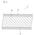
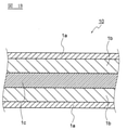
本実施形態に係るR-T-B系焼結磁石1は、図1Aおよび図2に示すように、主に逆コアシェル主相粒子11からなる逆コアシェル粒子層1a、および、主にコアシェル主相粒子13からなるコアシェル粒子層1bを有する。逆コアシェル主相粒子11およびコアシェル主相粒子13はR2T14B結晶からなる主相粒子である。また、各主相粒子間に粒界12が存在していてもよい。
As shown in FIGS. 1A and 2, the RTB-based
図2に示すように、逆コアシェル主相粒子11はコア部11aおよびコア部11aを被覆するシェル部11bを有する。また、コアシェル主相粒子13はコア部13aおよびコア部13aを被覆するシェル部13bを有する。なお、各主相粒子がコアシェル構造を有している粒子、すなわち逆コアシェル主相粒子11またはコアシェル主相粒子13であることは、SEMを用いて倍率1000倍以上10000倍以下で観察することにより確認できる。
As shown in FIG. 2, the inverted core shell
具体的には、本実施形態に係るR-T-B系焼結磁石1を切断して得られる断面を鏡面研磨してからSEMで反射電子像を撮影する。反射電子像にて生じる組成コントラストから各主相粒子がコアシェル主相粒子13であるか逆コアシェル主相粒子11であるかを判別できる。一般的に、組成コントラストは観察対象の平均原子番号が大きくなるほど明るく(白く)なる。また、重希土類元素RHはその他のR-T-B系焼結磁石1に含まれる元素と比較して原子番号が大きい。したがって、重希土類元素RHの濃度が相対的に高い領域は重希土類元素RHの濃度が相対的に低い領域と比較して平均原子番号が大きくなる。そして、反射電子像にて主相粒子内部でRH濃度が高い領域はRH濃度が低い領域と比較して明るく(白く)なる。以上より、主相粒子内部で明るい部分の位置によって各主相粒子がコアシェル主相粒子13であるか逆コアシェル主相粒子11であるかを判別できる。
Specifically, the cross section obtained by cutting the RTB-based
ここで、逆コアシェル主相粒子11は、前記R2T14B結晶からなる主相粒子であって、コア部11aにおける全RH濃度(at%)をCRC、シェル部11bにおける全RH濃度(at%)をCRSとした場合に、CRC/CRS>1.0である主相粒子である。
Here, the reverse core shell
すなわち、逆コアシェル主相粒子11は、一般的に知られているコアシェル主相粒子とは逆に、シェル部11bにおける全RH濃度よりもコア部11aにおける全RH濃度の方が高い主相粒子である。
That is, the reverse core-shell
CRCおよびCRSの測定箇所には、特に制限はない。例えば、以下の通りとすることができる。 There are no particular restrictions on the measurement points of C RC and C RS . For example, it can be as follows.
まず、濃度を測定する逆コアシェル主相粒子11を透過型電子顕微鏡(TEM)で観察し、長さが最大となる直径を特定する。次に、当該直径と粒界との二つの交点を特定する。そして、当該二つの交点の中点を中心とする20nm×20nmの領域における全RH濃度を測定し、コア部における全RH濃度CRCとすることができる。
First, the inverted core-shell
次に、当該二つの交点のうち一つの交点を選択する。そして、当該交点から前記長さが最大となる直径に沿って20nm、逆コアシェル主相粒子側に侵入した点を中心とする20nm×20nmの領域における全RH濃度を測定し、シェル部における全RH濃度CRSとすることができる。 Next, one of the two intersections is selected. Then, the total RH concentration in the region of 20 nm × 20 nm centered on the point invading the reverse core shell main phase particle side at 20 nm along the diameter at which the length becomes maximum from the intersection is measured, and the total RH in the shell portion is measured. It can be a concentration C RS .
一方、コアシェル主相粒子13とは、前記R2T14B結晶からなる主相粒子であって、コア部13aにおける全RH濃度(at%)をCNC、シェル部13bにおける全RH濃度(at%)をCNSとした場合に、CNC/CNS<1.0である主相粒子である。
On the other hand, the core-shell
すなわち、コアシェル主相粒子13は、一般的に知られているコアシェル主相粒子と同様に、シェル部13bにおける全RH濃度よりもコア部13aにおける全RH濃度の方が低い主相粒子である。
That is, the core-shell
CNCおよびCNSの測定箇所には、特に制限はないが、例えばCRCおよびCRSと同様に測定箇所を設定することができる。 The measurement points of C NC and C NS are not particularly limited, but measurement points can be set in the same manner as, for example, C RC and C RS .
また、逆コアシェル主相粒子11のコア部11aにおける全R濃度に対する全RH濃度には特に制限はないが、概ね原子比で30%以上80%以下程度である。逆コアシェル主相粒子11のシェル部11bにおける全R濃度に対する全RH濃度には特に制限はないが、概ね原子比で10%以上30%以下程度である。
Further, the total RH concentration with respect to the total R concentration in the
また、コアシェル主相粒子13のコア部13aにおける全R濃度に対する全RH濃度には特に制限はないが、概ね原子比で0%以上10%以下程度である。コアシェル主相粒子13のシェル部13bにおける全R濃度に対する全RH濃度には特に制限はないが、概ね原子比で10%以上30%以下程度である。
Further, the total RH concentration with respect to the total R concentration in the
以上より、通常は、逆コアシェル主相粒子11のコア部11aが最も全R濃度に対する全RH濃度が高く、コアシェル主相粒子13のコア部13aが最も全R濃度に対する全RH濃度が低くなる。なお、逆コアシェル主相粒子11のシェル部11bとコアシェル主相粒子13のシェル部13bとでは、全R濃度に対する全RH濃度は大きく変化しない。
From the above, usually, the
なお、図2では、逆コアシェル主相粒子11はコア部11aの表面全てをシェル部11bが覆っているが、コア部11aの表面全てをシェル部11bが覆う必要はなく、コア部11aの表面の60%以上を覆っていればよい。コア部11aおよびシェル部11bの区別はSEMにより行うことができる。コアシェル主相粒子13についても同様である。
In FIG. 2, the reverse core shell
本実施形態に係るR-T-B系焼結磁石1は、逆コアシェル主相粒子11を含むことにより、重希土類元素の使用量を低減しても高い磁気特性を有する永久磁石となる。逆コアシェル主相粒子11を含むことにより上記の効果が得られるメカニズムは、以下に示すメカニズムであると考えられる。
The RTB-based
逆コアシェル主相粒子11は、シェル部11bと比較してより多くのRHを含むことにより、コア部11aにおいて異方性磁界が高くなる。そのため、逆コアシェル主相粒子11のコア部11aとシェル部11bとの界面において、異方性磁界が変化すると考えられる。上記の逆コアシェル主相粒子11内での異方性磁界の変化により、ピニング力が増加すると考えられる。したがって、逆コアシェル主相粒子11を含むR-T-B系焼結磁石1は保磁力が向上すると考えられる。
Since the inverted core shell
また、図1Aおよび図2に示すように、全主相粒子に対する逆コアシェル主相粒子11の存在比率は、磁石中央部よりも磁石表層部の方が高い。そして、主に逆コアシェル主相粒子11からなる逆コアシェル粒子層1aが磁石表層部に存在していることが好ましい。
Further, as shown in FIGS. 1A and 2, the abundance ratio of the reverse core shell
逆コアシェル主相粒子11はコア部11aにより多くの重希土類元素RHを含有する。そのため、逆コアシェル主相粒子11自体は残留磁束密度および飽和磁化が低い。逆コアシェル主相粒子11は飽和磁化が低いため、ある逆コアシェル主相粒子11が磁化反転しても、当該逆コアシェル主相粒子11に隣接する主相粒子の磁化反転に及ぼす影響が小さい。すなわち、主に逆コアシェル主相粒子11からなる逆コアシェル粒子層1aがR-T-B系焼結磁石1の磁石表層部に存在していることにより、磁石表面から発生する逆磁区の伝達が抑制される。したがって、逆コアシェル主相粒子11が磁石表層部により多く存在し、逆コアシェル粒子層1aが磁石表層部に存在していることにより、R-T-B系焼結磁石1は保磁力がさらに向上する。
The inverted core-shell
本実施形態に係るR-T-B系焼結磁石1に含まれる逆コアシェル主相粒子11において、CRC/CRS>1.5であることが好ましく、CRC/CRS>3.0であることがより好ましい。逆コアシェル主相粒子11において、シェル部11bに対してコア部11aに重希土類元素RHがより多く存在するほど上記の効果が大きくなり、保磁力がさらに向上するため好ましい。
In the reverse core shell
なお、本実施形態では、磁石表層部とは、磁石表面から磁石内部に向かって5μm以上150μm以下の領域を指す。磁石中央部とは、磁石表層部より内側にある部分を指す。また、逆コアシェル粒子層1aはR-T-B系焼結磁石1の全ての磁石表層部に存在している必要はなく、一部の磁石表層部のみに存在していてもよい。また、図2に示すように、逆コアシェル粒子層1aは逆コアシェル主相粒子11が存在している層を指す。また、コアシェル粒子層1bはコアシェル主相粒子13が存在し、逆コアシェル主相粒子11が存在していない層を指す。
In the present embodiment, the magnet surface layer portion refers to a region of 5 μm or more and 150 μm or less from the magnet surface toward the inside of the magnet. The central portion of the magnet refers to a portion inside the surface layer portion of the magnet. Further, the reverse core-
逆コアシェル粒子層1aの厚さには特に制限はない。10μm以上100μm以下とすることが好ましい。
The thickness of the inverted core-
また、本実施形態に係るR-T-B系焼結磁石は、図1Aに示すように、磁石中央部から磁石表層部に向かってコアシェル粒子層1bおよび逆コアシェル粒子層1aがこの順番で並んでいても良い。また、逆コアシェル粒子層1aおよびコアシェル粒子層1bのみからなっていてもよい。
Further, in the RTB-based sintered magnet according to the present embodiment, as shown in FIG. 1A, the core-
<R-T-B系焼結磁石の製造方法>
次に、本実施形態に係るR-T-B系焼結磁石の製造方法を説明する。
<Manufacturing method of RTB-based sintered magnet>
Next, a method for manufacturing the RTB-based sintered magnet according to the present embodiment will be described.
なお、以下では、粉末冶金法で作製され、重希土類元素が粒界拡散されたR-T-B系焼結磁石を例に説明するが、本実施形態に係るR-T-B系焼結磁石の製造方法は、特に限定されるものではなく、他の方法も用いることができる。 In the following, an RTB-based sintered magnet manufactured by a powder metallurgy method and having a heavy rare earth element diffused at the grain boundary will be described as an example, but the RTB-based sintered magnet according to the present embodiment will be described. The method for manufacturing the magnet is not particularly limited, and other methods can also be used.
本実施形態に係るR-T-B系焼結磁石の製造方法には、原料粉末を成形して成形体を得る成形工程と、前記成形体を焼結して焼結体を得る焼結工程と、前記焼結体を焼結温度よりも低い温度で一定時間保持する時効工程とを有する。 The method for manufacturing an RTB-based sintered magnet according to the present embodiment includes a molding step of molding a raw material powder to obtain a molded body and a sintering step of sintering the molded body to obtain a sintered body. And an aging step of holding the sintered body at a temperature lower than the sintering temperature for a certain period of time.
以下、R-T-B系焼結磁石の製造方法について詳しく説明していくが、特記しない事項については、公知の方法を用いればよい。 Hereinafter, the method for manufacturing the RTB-based sintered magnet will be described in detail, but for matters not otherwise specified, a known method may be used.
[原料粉末の準備工程]
原料粉末は、公知の方法により作製することができる。本実施形態では、主にR2T14B相からなる一種類の原料合金を用いる一合金法でR-T-B系焼結磁石を製造するが、二種類の原料合金を用いる二合金法により製造してもよい。ここで、原料合金の組成は、最終的に得るR-T-B系焼結磁石の組成となるように制御する。
[Preparation process of raw material powder]
The raw material powder can be produced by a known method. In the present embodiment, the RTB-based sintered magnet is manufactured by a one-alloy method using one kind of raw material alloy mainly composed of R 2 T 14 B phase, but a two-alloy method using two kinds of raw material alloys. May be manufactured by Here, the composition of the raw material alloy is controlled so as to be the composition of the RTB-based sintered magnet finally obtained.
まず、本実施形態に係る原料合金の組成に対応する原料金属を準備し、当該原料金属から本実施形態に対応する原料合金を作製する。原料合金の作製方法に特に制限はない。例えば、ストリップキャスト法にて原料合金を作製することができる。 First, a raw material metal corresponding to the composition of the raw material alloy according to the present embodiment is prepared, and a raw material alloy corresponding to the present embodiment is produced from the raw material metal. There are no particular restrictions on the method for producing the raw material alloy. For example, a raw material alloy can be produced by a strip casting method.
原料合金を作製した後に、作製した原料合金を粉砕する(粉砕工程)。粉砕工程は、2段階で実施してもよく、1段階で実施してもよい。粉砕の方法には特に限定はない。例えば、各種粉砕機を用いる方法で実施される。例えば、粉砕工程を粗粉砕工程および微粉砕工程の2段階で実施し、粗粉砕工程は例えば水素粉砕処理を行うことが可能である。具体的には、原料合金に対して室温で水素を吸蔵させた後に、Arガス雰囲気下で400℃以上650℃以下、0.5時間以上2時間以下で脱水素を行うことが可能である。また、微粉砕工程は、粗粉砕後の粉末に対して、例えばオレイン酸アミド、ステアリン酸亜鉛などを添加したのちに、例えばジェットミル、湿式アトライター等を用いて行うことができる。得られる微粉砕粉末(原料粉末)の粒径には特に制限はない。例えば、粒径(D50)が1μm以上10μm以下の微粉砕粉末(原料粉末)となるように微粉砕を行うことができる。 After producing the raw material alloy, the produced raw material alloy is crushed (crushing step). The crushing step may be carried out in two steps or in one step. The crushing method is not particularly limited. For example, it is carried out by a method using various crushers. For example, the pulverization step can be carried out in two stages, a coarse pulverization step and a fine pulverization step, and the coarse pulverization step can be, for example, a hydrogen pulverization treatment. Specifically, it is possible to occlude hydrogen in the raw material alloy at room temperature and then dehydrogenate in an Ar gas atmosphere at 400 ° C. or higher and 650 ° C. or lower, and 0.5 hours or longer and 2 hours or lower. Further, the fine pulverization step can be performed by adding, for example, oleic acid amide, zinc stearate, or the like to the powder after coarse pulverization, and then using, for example, a jet mill, a wet attritor, or the like. The particle size of the obtained finely pulverized powder (raw material powder) is not particularly limited. For example, fine pulverization can be performed so that the finely pulverized powder (raw material powder) having a particle size (D50) of 1 μm or more and 10 μm or less is obtained.
[成形工程]
成形工程では、粉砕工程により得られた微粉砕粉末(原料粉末)を所定の形状に成形する。成形方法には特に限定はないが、本実施形態では、微粉砕粉末(原料粉末)を金型内に充填し、磁場中で加圧する。
[Molding process]
In the molding step, the finely crushed powder (raw material powder) obtained in the crushing step is molded into a predetermined shape. The molding method is not particularly limited, but in the present embodiment, the finely pulverized powder (raw material powder) is filled in the mold and pressurized in a magnetic field.
成形時の加圧は、30MPa以上300MPa以下で行うことが好ましい。印加する磁場は、950kA/m以上1600kA/m以下であることが好ましい。微粉砕粉末(原料粉末)を成形して得られる成形体の形状は特に限定されるものではなく、例えば直方体、平板状、柱状等、所望とするR-T-B系焼結磁石の形状に応じて任意の形状とすることができる。 The pressurization during molding is preferably performed at 30 MPa or more and 300 MPa or less. The applied magnetic field is preferably 950 kA / m or more and 1600 kA / m or less. The shape of the molded body obtained by molding the finely pulverized powder (raw material powder) is not particularly limited, and the desired shape of the RTB-based sintered magnet such as a rectangular parallelepiped, a flat plate, or a columnar shape can be obtained. It can have any shape depending on the shape.
[焼結工程]
焼結工程は、成形体を真空または不活性ガス雰囲気中で焼結し、焼結体を得る工程である。焼結温度は、組成、粉砕方法、粒度と粒度分布の違い等、諸条件により調整する必要があるが、成形体に対して、例えば、真空中または不活性ガスの存在下、1000℃以上1200℃以下、1時間以上10時間以下で加熱する処理を行うことにより焼結する。これにより、高密度の焼結体(焼結磁石)が得られる。
[Sintering process]
The sintering step is a step of sintering a molded body in a vacuum or an atmosphere of an inert gas to obtain a sintered body. The sintering temperature needs to be adjusted according to various conditions such as composition, pulverization method, difference in particle size and particle size distribution, etc. Sintering is performed by heating at a temperature of 1 ° C. or higher and 1 hour or longer and 10 hours or lower. As a result, a high-density sintered body (sintered magnet) can be obtained.
[時効処理工程]
時効処理工程は、焼結工程後の焼結体(焼結磁石)に対して、焼結温度よりも低い温度で加熱することにより行う。時効処理の温度および時間には特に制限はないが、例えば450℃以上900℃以下で0.2時間以上3時間以下、行うことができる。なお、この時効処理工程は省略してもよい。
[Aging process]
The aging treatment step is performed by heating the sintered body (sintered magnet) after the sintering step at a temperature lower than the sintering temperature. The temperature and time of the aging treatment are not particularly limited, but can be carried out, for example, at 450 ° C. or higher and 900 ° C. or lower for 0.2 hours or longer and 3 hours or shorter. The aging treatment step may be omitted.
また、時効処理工程は1段階で行ってもよく、2段階で行ってもよい。2段階で行う場合には、例えば1段階目を700℃以上900℃以下で0.2時間以上3時間以下とし、2段階目を450℃以上700℃以下で0.2時間以上3時間以下としてもよい。また、1段階目と2段階目とを連続して行ってもよく、1段階目の後に一度室温近傍まで冷却してから再加熱して2段階目を行ってもよい。 Further, the aging treatment step may be performed in one step or in two steps. In the case of performing in two steps, for example, the first step is set to 700 ° C. or higher and 900 ° C. or lower for 0.2 hours or more and 3 hours or less, and the second step is set to 450 ° C. or higher and 700 ° C. or lower for 0.2 hours or more and 3 hours or less. May be good. Further, the first step and the second step may be continuously performed, or after the first step, the first step may be cooled to near room temperature and then reheated to perform the second step.
[逆コアシェル主相粒子生成工程]
本実施形態における逆コアシェル主相粒子の生成方法には特に制限がない。例えば、以下に示す分解工程、粒界拡散工程および再結晶化工程を経ることで逆コアシェル主相粒子を得ることができる。
[Reverse core shell main phase particle generation process]
There is no particular limitation on the method for producing the inverted core shell main phase particles in the present embodiment. For example, the reverse core shell main phase particles can be obtained through the following decomposition steps, grain boundary diffusion steps, and recrystallization steps.
[分解工程]
分解工程とは、主に磁石表層部に存在するR2T14B結晶からなる主相粒子を分解不均化する工程である。分解工程の条件は、主に磁石表層部に存在するR2T14B結晶からなる主相粒子を分解させることができれば特に制限はない。
[Disassembly process]
The decomposition step is a step of decomposing and disproportionating the main phase particles composed of R 2 T 14 B crystals mainly present on the surface layer of the magnet. The conditions of the decomposition step are not particularly limited as long as the main phase particles composed of R 2 T 14 B crystals mainly present on the surface layer of the magnet can be decomposed.
例えばH2ガス、COガスまたはN2ガスを含む不活性雰囲気中、600℃以上900℃以下程度で5分間以上60分間以下程度、加熱することで、主に磁石表層部に存在する主相粒子にH2、COまたはN2を吸蔵させて分解させ、不均化させることになる。 For example, by heating in an inert atmosphere containing H 2 gas, CO gas or N 2 gas at 600 ° C. or higher and 900 ° C. or lower for 5 minutes or longer and 60 minutes or lower, the main phase particles mainly present on the surface layer of the magnet. H 2 , CO or N 2 is occluded and decomposed to disproportionate.
H2ガス、COガスまたはN2ガスの濃度、加熱温度および/または加熱時間を制御することで、主相粒子が不均化する領域の厚さを制御し、最終的に得られる逆コアシェル粒子層の厚さを制御することができる。 By controlling the concentration of H 2 gas, CO gas or N 2 gas, heating temperature and / or heating time, the thickness of the region where the main phase particles disproportionate is controlled, and the finally obtained inverted core shell particles. The thickness of the layer can be controlled.
また、酸化性ガスを含む酸化性雰囲気中、300℃以上500℃以下程度で20分間以上60分間以下程度、加熱することでも、磁石表層部に存在する主相粒子を分解不均化させることができる。 Further, the main phase particles existing on the surface layer of the magnet can be decomposed and disproportionated by heating at 300 ° C. or higher and 500 ° C. or lower for 20 minutes or longer and 60 minutes or lower in an oxidizing atmosphere containing an oxidizing gas. can.
[拡散処理工程]
本実施形態では、分解工程に続いて、さらに重希土類元素を拡散させる拡散処理工程を有する。拡散処理は、重希土類元素を含む化合物等を、前記分解工程を行った焼結体の表面に付着させた後、熱処理を行うことにより、実施することができる。重希土類元素を含む化合物を付着させる方法には特に制限はなく、たとえば重希土類元素を含むスラリーを塗布することで付着させることができる。この場合には、スラリーの塗布量とスラリーに含まれる重希土類元素の濃度を制御することで、上記のCRC/CRSを制御することができる。
[Diffusion processing process]
In the present embodiment, following the decomposition step, there is a diffusion treatment step of further diffusing heavy rare earth elements. The diffusion treatment can be carried out by adhering a compound or the like containing a heavy rare earth element to the surface of the sintered body subjected to the decomposition step, and then performing a heat treatment. The method for adhering the compound containing the heavy rare earth element is not particularly limited, and for example, the compound can be attached by applying a slurry containing the heavy rare earth element. In this case, the above C RC / C RS can be controlled by controlling the coating amount of the slurry and the concentration of the heavy rare earth element contained in the slurry.
ただし、前記重希土類元素を付着させる方法は特に制限は無い。例えば、蒸着、スパッタリング、電着、スプレー塗布、刷毛塗り、ジェットディスペンサ、ノズル、スクリーン印刷、スキージ印刷、シート工法等を用いる方法がある。 However, the method of adhering the heavy rare earth element is not particularly limited. For example, there are methods using vapor deposition, sputtering, electrodeposition, spray coating, brush coating, jet dispenser, nozzle, screen printing, squeegee printing, sheet construction method and the like.
重希土類化合物は粒子状であることが好ましい。また、平均粒径は100nm以上50μm以下であることが好ましく、1μm以上10μm以下であることがより好ましい。 The heavy rare earth compound is preferably in the form of particles. The average particle size is preferably 100 nm or more and 50 μm or less, and more preferably 1 μm or more and 10 μm or less.
スラリーに用いる溶媒としては、重希土類化合物を溶解させずに均一に分散させ得るものが好ましい。例えば、アルコール、アルデヒド、ケトン等が挙げられ、なかでもエタノールが好ましい。 As the solvent used for the slurry, a solvent capable of uniformly dispersing the heavy rare earth compound without dissolving it is preferable. For example, alcohols, aldehydes, ketones and the like can be mentioned, with ethanol being preferred.
スラリー中の重希土類化合物の含有量には特に制限はない。例えば、50重量%以上90重量%以下であってもよい。スラリーには、必要に応じて重希土類化合物以外の成分をさらに含有させてもよい。例えば、重希土類化合物粒子の凝集を防ぐための分散剤等が挙げられる。 The content of the heavy rare earth compound in the slurry is not particularly limited. For example, it may be 50% by weight or more and 90% by weight or less. If necessary, the slurry may further contain components other than the heavy rare earth compound. For example, a dispersant for preventing agglomeration of heavy rare earth compound particles can be mentioned.
上記の拡散処理工程を、前記分解工程を行った焼結体に対して行うことにより、焼結体全体の粒界に加えて、磁石表層部に存在する主相粒子が分解不均化された領域においては融点の低下に伴い液相が生成し、重希土類元素RHが液相中に拡散することになる。そして、Rとして重希土類元素RHを含むR2T14B結晶はRとして重希土類元素RHを含まないR2T14B結晶よりも生成しやすいため、拡散した重希土類元素を含む液相が部分的にR2T14B結晶化し、主に最終的に得られる逆コアシェル主相粒子のコア部となる。 By performing the above diffusion treatment step on the sintered body subjected to the decomposition step, in addition to the grain boundaries of the entire sintered body, the main phase particles existing on the surface layer of the magnet were decomposed and disproportionated. In the region, a liquid phase is generated as the melting point decreases, and the heavy rare earth element RH diffuses into the liquid phase. Since the R 2 T 14 B crystal containing the heavy rare earth element RH as R is easier to form than the R 2 T 14 B crystal containing no heavy rare earth element RH as R, the liquid phase containing the diffused heavy rare earth element is partially formed. R 2 T 14 B crystallizes and becomes the core part of the main phase particles of the inverted core shell that is finally obtained.
拡散処理工程の条件には特に制限はないが、650℃以上1000℃以下で1時間以上24時間以下、行うことが好ましい。上記の範囲内の温度および時間とすることで、液相に取り込まれる重希土類元素RHの割合を多くしやすくなる。また、拡散処理工程の際に、上記のH2ガス、COガス、N2ガスまたは酸化性ガスに含まれる各成分が放出される。 The conditions of the diffusion treatment step are not particularly limited, but it is preferably performed at 650 ° C. or higher and 1000 ° C. or lower for 1 hour or longer and 24 hours or shorter. By setting the temperature and time within the above range, it becomes easy to increase the ratio of the heavy rare earth element RH incorporated into the liquid phase. Further, during the diffusion treatment step, each component contained in the above-mentioned H 2 gas, CO gas, N 2 gas or oxidizing gas is released.
[再結晶化工程]
拡散処理工程後に再結晶化工程を経ることにより、重希土類元素RHが取り込まれた液相のうち、粒界拡散工程で結晶化しなかった液相も結晶化され、R2T14B結晶となる。再結晶化工程は、例えば、50℃/分以上500℃/分以下の速度で急冷を行うことにより行われる。再結晶化工程により、拡散処理工程の際に結晶化された重希土類元素RHの含有量が多いR2T14B結晶の周囲に存在する液相も結晶化する。さらに、再結晶化工程においては、重希土類元素RHの含有量が多いR2T14B結晶から発生し始め、重希土類元素RHの含有量が少ないR2T14B結晶が重希土類元素RHの含有量が多いR2T14B結晶の周囲に形成される傾向にある。その結果、逆コアシェル主相粒子が形成される。冷却速度には特に制限はないが、冷却速度が速すぎると非晶質および副相を多く含んだ微結晶になる傾向にあり、冷却速度が遅すぎると逆コアシェル主相粒子11のコア部11aとシェル部11bとの界面が不明瞭になる傾向にある。
[Recrystallization step]
By going through the recrystallization step after the diffusion treatment step, among the liquid phases in which the heavy rare earth element RH is incorporated, the liquid phase that was not crystallized in the grain boundary diffusion step is also crystallized to become R 2 T 14 B crystals. .. The recrystallization step is performed, for example, by quenching at a rate of 50 ° C./min or more and 500 ° C./min or less. By the recrystallization step, the liquid phase existing around the R 2 T 14 B crystal having a high content of the heavy rare earth element RH crystallized in the diffusion treatment step is also crystallized. Further, in the recrystallization step, the R 2 T 14 B crystal having a high content of the heavy rare earth element RH starts to be generated, and the R 2 T 14 B crystal having a low content of the heavy rare earth element RH is the heavy rare earth element RH. It tends to be formed around R 2 T 14 B crystals with high content. As a result, inverted core-shell main phase particles are formed. The cooling rate is not particularly limited, but if the cooling rate is too fast, it tends to be amorphous and microcrystals containing a large amount of secondary phases, and if the cooling rate is too slow, the
以上より、本実施形態に係るR-T-B系焼結磁石の製造方法としては、少なくとも、磁石表層部の主相粒子を分解不均化する分解工程、液相を生成し前記液相に重希土類元素を拡散させる粒界拡散工程、および部分的に結晶化したR2T14B結晶の周囲の液相を結晶化させる再結晶化工程がこの順で行われることが重要である。これにより、R-T-B系焼結磁石の磁石表層部に逆コアシェル主相粒子を発生させ、逆コアシェル粒子層を形成することができる。上記の分解工程、粒界拡散工程、および再結晶化工程の方法および条件はあくまでも例示である。分解工程は磁石表層部の主相粒子を分解不均化する工程であればよい。粒界拡散工程は液相を生成し、前記液相に重希土類元素を拡散させることができればよい。再結晶化工程は再結晶により逆コアシェル主相粒子を発生させ、逆コアシェル粒子層を形成させることができればよい。 Based on the above, as a method for manufacturing an RTB-based sintered magnet according to the present embodiment, at least a decomposition step of decomposing and disproportionating the main phase particles on the surface layer of the magnet and a liquid phase are generated and the liquid phase is formed. It is important that the grain boundary diffusion step of diffusing the heavy rare earth elements and the recrystallization step of crystallizing the liquid phase around the partially crystallized R 2 T 14 B crystal are performed in this order. As a result, the reverse core-shell main phase particles can be generated on the magnet surface layer portion of the RTB-based sintered magnet to form the reverse core-shell particle layer. The methods and conditions of the decomposition step, the grain boundary diffusion step, and the recrystallization step are merely examples. The decomposition step may be any step as long as it is a step of decomposing and disproportionating the main phase particles on the surface layer of the magnet. The grain boundary diffusion step only needs to be able to generate a liquid phase and diffuse heavy rare earth elements into the liquid phase. In the recrystallization step, it is sufficient that the reverse core shell main phase particles can be generated by recrystallization to form the reverse core shell particle layer.
なお、分解工程にて分解不均化しなかった主相粒子については、粒界拡散工程において粒界拡散された重希土類元素RHによりシェル部が形成され、通常のコアシェル主相粒子となり、コアシェル粒子層を形成する。 For the main phase particles that were not decomposed and disproportionated in the decomposition step, a shell portion was formed by the heavy rare earth element RH diffused at the grain boundary diffusion step to become normal core shell main phase particles, and the core shell particle layer. To form.
[再時効処理工程]
再時効処理工程は、再結晶化工程後の焼結磁石に対して、拡散処理工程の最高温度よりも低い温度で加熱することにより行う。再時効処理の温度および時間には特に制限はないが、例えば450℃以上800℃以下で0.2時間以上3時間以下、行うことができる。
[Re-aging process]
The reaging treatment step is performed by heating the sintered magnet after the recrystallization step at a temperature lower than the maximum temperature of the diffusion treatment step. The temperature and time of the re-aging treatment are not particularly limited, but can be carried out, for example, at 450 ° C. or higher and 800 ° C. or lower for 0.2 hours or longer and 3 hours or shorter.
以上の工程により得られたR-T-B系焼結磁石は、めっきや樹脂被膜や酸化処理、化成処理などの表面処理を施してもよい。これにより、耐食性をさらに向上させることができる。 The RTB-based sintered magnet obtained by the above steps may be subjected to surface treatment such as plating, resin coating, oxidation treatment, or chemical conversion treatment. Thereby, the corrosion resistance can be further improved.
さらに、本実施形態に係るR-T-B系焼結磁石を切断、分割して得られる磁石を用いることができる。 Further, a magnet obtained by cutting and dividing the RTB-based sintered magnet according to the present embodiment can be used.
具体的には、本実施形態に係るR-T-B系焼結磁石は、モータ、コンプレッサー、磁気センサー、スピーカ等の用途に好適に用いられる。 Specifically, the RTB-based sintered magnet according to the present embodiment is suitably used for applications such as motors, compressors, magnetic sensors, and speakers.
また、本実施形態に係るR-T-B系焼結磁石は、単独で用いてもよく、2個以上のR-T-B系焼結磁石を必要に応じて結合させて用いてもよい。結合方法に特に制限はない。例えば、機械的に結合させる方法や樹脂モールドで結合させる方法がある。 Further, the RTB-based sintered magnet according to the present embodiment may be used alone, or two or more RT-B-based sintered magnets may be combined and used as necessary. .. There are no particular restrictions on the joining method. For example, there are a method of mechanically bonding and a method of bonding with a resin mold.
2個以上のR-T-B系焼結磁石を結合させることで、大きなR-T-B系焼結磁石を容易に製造することができる。2個以上のR-T-B系焼結磁石を結合させた磁石は、特に大きなR-T-B系焼結磁石が求められる用途、例えば、IPMモータ、風力発電機、大型モータ等に好ましく用いられる。 By coupling two or more RTB-based sintered magnets, a large RTB-based sintered magnet can be easily manufactured. A magnet in which two or more RTB-based sintered magnets are coupled is preferable for applications in which a particularly large RTB-based sintered magnet is required, for example, an IPM motor, a wind power generator, a large motor, or the like. Used.
なお、本発明は、上述した実施形態のように、磁石中央部から磁石表層部に向かって、コアシェル粒子層1b、逆コアシェル粒子層1aの順番に並んでいる態様に限定されず、本発明の範囲内で種々に改変することができる。
The present invention is not limited to the embodiment in which the core-
例えば、図1Bに示すように、磁石中央部において、コアシェル粒子層1bに加えて、コアシェル構造を有さない非コアシェル主相粒子のみからなる非コアシェル粒子層1cが存在するR-T-B系焼結磁石10の実施形態が考えられる。そして、磁石中央部から磁石表層部に向かって、非コアシェル粒子層1c、コアシェル粒子層1b、逆コアシェル粒子層1aの順番に並んでいてもよい。また、逆コアシェル粒子層1a、コアシェル粒子層1bおよび非コアシェル粒子層1cのみからなっていてもよい。なお、主相粒子が「コアシェル構造を有さない」ことは、SEMを用いて倍率1000倍以上10000倍以下で観察した場合に、コアシェル構造が観察されないことにより確認できる。
For example, as shown in FIG. 1B, in the central portion of the magnet, in addition to the core-
非コアシェル粒子層1cが存在する場合(図1B)には、非コアシェル粒子層1cが存在しない場合(図1A)と比べて残留磁束密度Brが高くなる傾向にある。 When the non-core-shell particle layer 1c is present (FIG. 1B), the residual magnetic flux density Br tends to be higher than when the non-core-shell particle layer 1c is not present (FIG. 1A).
非コアシェル粒子層1cを存在させる方法にも特に制限はない。例えば粒界拡散工程において重希土類元素の付着量を調整する方法、粒界拡散工程において拡散処理時間を短くする方法などがある。 There is no particular limitation on the method for allowing the non-core shell particle layer 1c to exist. For example, there are a method of adjusting the adhesion amount of heavy rare earth elements in the grain boundary diffusion step, a method of shortening the diffusion treatment time in the grain boundary diffusion step, and the like.
次に、本発明を具体的な実施例に基づきさらに詳細に説明するが、本発明は、以下の実施例に限定されない。 Next, the present invention will be described in more detail based on specific examples, but the present invention is not limited to the following examples.
(焼結磁石作製工程)
原料金属として、Nd、電解鉄、低炭素フェロボロン合金を準備した。さらに、Al、Cu、Co、Zrを、純金属またはFeとの合金の形で準備した。
(Sintered magnet manufacturing process)
As a raw material metal, Nd, electrolytic iron, and a low carbon ferroboron alloy were prepared. Further, Al, Cu, Co and Zr were prepared in the form of a pure metal or an alloy with Fe.
前記原料金属に対し、ストリップキャスト法により、焼結磁石の組成が後述する表1の合金Aに示す組成となるように焼結体用合金(原料合金)を作製した。表1に示した各元素の含有量(重量%)はNd、B、Al、Cu、Co、ZrおよびFeの合計含有量を100重量%としたときの値である。また、前記原料合金の合金厚みは0.2mm以上0.6mm以下とした。 An alloy for a sintered body (raw material alloy) was prepared from the raw material metal by a strip casting method so that the composition of the sintered magnet had the composition shown in the alloy A in Table 1 described later. The content (% by weight) of each element shown in Table 1 is a value when the total content of Nd, B, Al, Cu, Co, Zr and Fe is 100% by weight. The alloy thickness of the raw material alloy was set to 0.2 mm or more and 0.6 mm or less.
次いで、前記原料合金に対して室温で1時間、水素ガスをフローさせて水素を吸蔵させた。次いで雰囲気をArガスに切り替え、450℃で1時間、脱水素処理を行い、原料合金を水素粉砕した。さらに、冷却後にふるいを用いて400μm以下の粒度の粉末とした。 Next, hydrogen gas was allowed to flow through the raw material alloy at room temperature for 1 hour to occlude hydrogen. Next, the atmosphere was switched to Ar gas, dehydrogenation treatment was performed at 450 ° C. for 1 hour, and the raw material alloy was pulverized with hydrogen. Further, after cooling, a sieve was used to prepare a powder having a particle size of 400 μm or less.
次いで、水素粉砕後の原料合金の粉末に対し、重量比で0.1%のオレイン酸アミドを粉砕助剤として添加し、混合した。 Next, 0.1% oleic acid amide by weight was added as a pulverizing aid to the powder of the raw material alloy after hydrogen pulverization, and the mixture was mixed.
次いで、衝突板式のジェットミル装置を用いて窒素気流中で微粉砕し、それぞれ平均粒径が4μm程度の微粉(原料粉末)とした。なお、前記平均粒径は、レーザ回折式の粒度分布計で測定した平均粒径D50である。 Then, it was finely pulverized in a nitrogen stream using a collision plate type jet mill device to obtain fine powder (raw material powder) having an average particle size of about 4 μm. The average particle size is the average particle size D50 measured by a laser diffraction type particle size distribution meter.
なお、表1に記載していない元素では、H、Si、Ca、La、Ce、Cr等が検出される場合がある。Siは主にフェロボロン原料および合金溶解時のるつぼから混入する。Ca、La、Ceは希土類の原料から混入する。また、Crは電解鉄から混入する可能性がある。 For elements not listed in Table 1, H, Si, Ca, La, Ce, Cr and the like may be detected. Si is mainly mixed from the ferroboron raw material and the crucible at the time of melting the alloy. Ca, La and Ce are mixed from rare earth raw materials. In addition, Cr may be mixed from electrolytic iron.
得られた微粉を磁界中で成形して成形体を作製した。このときの印加磁場は1200kA/mの静磁界である。また、成形時の加圧力は120MPaとした。なお、磁界印加方向と加圧方向とを直交させるようにした。この時点での成形体の密度を測定したところ、全ての成形体の密度が4.10Mg/m3以上4.25Mg/m3以下の範囲内であった。 The obtained fine powder was molded in a magnetic field to prepare a molded product. The applied magnetic field at this time is a static magnetic field of 1200 kA / m. The pressing force during molding was 120 MPa. The magnetic field application direction and the pressurization direction were made orthogonal to each other. When the density of the molded product was measured at this time, the density of all the molded products was in the range of 4.10 Mg / m 3 or more and 4.25 Mg / m 3 or less.
次に、前記成形体を焼結し、焼結磁石を得た。焼結条件は、1060℃で4時間保持とした。焼結雰囲気は真空中とした。このとき焼結密度は7.50Mg/m3以上7.55Mg/m3以下の範囲にあった。その後、Ar雰囲気、大気圧中で、第一時効温度T1=900℃で1時間の第一時効処理を行い、さらに、第二時効温度T2=500℃で1時間の第二時効処理を行った。 Next, the molded body was sintered to obtain a sintered magnet. The sintering conditions were 1060 ° C. for 4 hours. The sintering atmosphere was in vacuum. At this time, the sintering density was in the range of 7.50 Mg / m 3 or more and 7.55 Mg / m 3 or less. Then, in an Ar atmosphere and atmospheric pressure, a first temporary aging treatment was performed at a first temporary aging temperature T1 = 900 ° C. for 1 hour, and a second aging treatment was further performed at a second aging temperature T2 = 500 ° C. for 1 hour. ..
得られた焼結磁石の組成は蛍光X線分析で評価した。Bの含有量はICPで評価した。各試料における焼結磁石の組成が表2の通りであることを確認した。そして、得られた焼結磁石に対し、以下に示す各実施例1~22および比較例1~6の処理を行った。 The composition of the obtained sintered magnet was evaluated by fluorescent X-ray analysis. The content of B was evaluated by ICP. It was confirmed that the composition of the sintered magnet in each sample is as shown in Table 2. Then, the obtained sintered magnets were subjected to the treatments of Examples 1 to 22 and Comparative Examples 1 to 6 shown below.
(実施例1)
上記の工程により得られた焼結磁石を、幅20mm、長さ20mm、配向方向の厚み5mmの直方体となるように加工した後、水素が5体積%、Arが95体積%である雰囲気ガス中、750℃で10分間保持し、主に磁石表層部に存在する主相粒子を分解不均化した。
(Example 1)
The sintered magnet obtained by the above step is processed into a rectangular parallelepiped having a width of 20 mm, a length of 20 mm, and a thickness of 5 mm in the orientation direction, and then in an atmospheric gas containing 5% by volume of hydrogen and 95% by volume of Ar. , The main phase particles present mainly on the surface layer of the magnet were decomposed and disproportionated by holding at 750 ° C. for 10 minutes.
次いで、焼結磁石の全面に対し、TbH2粒子(平均粒径D50=5μm)をエタノールに分散させたスラリーを、焼結磁石の重量に対するTbの重量が0.5重量%となるように塗布することでTbを付着させた。前記スラリーを塗布後に大気圧でArをフローしながら770℃で5時間の熱処理を実施し、続いて950℃で5時間の熱処理を施し、Tbを粒界拡散させた。 Next, a slurry in which two TbH particles (average particle size D50 = 5 μm) are dispersed in ethanol is applied to the entire surface of the sintered magnet so that the weight of Tb is 0.5% by weight based on the weight of the sintered magnet. By doing so, Tb was attached. After the slurry was applied, heat treatment was performed at 770 ° C. for 5 hours while flowing Ar at atmospheric pressure, and then heat treatment was performed at 950 ° C. for 5 hours to diffuse Tb at grain boundaries.
前記熱処理後に冷却速度200℃/分で急冷し、液相からR2T14B結晶を再結晶化させた。 After the heat treatment, the mixture was rapidly cooled at a cooling rate of 200 ° C./min to recrystallize R 2T 14B crystals from the liquid phase.
その後、Ar雰囲気、大気圧中で、500℃で1時間の再時効処理を行った。 Then, it was re-aged at 500 ° C. for 1 hour in an Ar atmosphere and atmospheric pressure.
前記再時効処理後の焼結磁石について、BHトレーサーで磁気特性(残留磁束密度Br、保磁力Hcjおよび角形比Hk/Hcj)の評価を行った。 The magnetic characteristics (residual magnetic flux density Br, coercive force Hcj and square ratio Hk / Hcj) of the sintered magnet after the re-aging treatment were evaluated with a BH tracer.
(実施例2)
上記の工程により得られた焼結磁石をCOが8体積%、Arが92体積%である雰囲気ガス中、700℃で10分間保持し、主に磁石表層部に存在する主相粒子を分解不均化した。
(Example 2)
The sintered magnet obtained by the above step is held at 700 ° C. for 10 minutes in an atmospheric gas containing 8% by volume of CO and 92% by volume of Ar, and the main phase particles mainly present on the surface layer of the magnet are not decomposed. Smoothed out.
次いで、焼結磁石の全面に対し、TbH2粒子(平均粒径D50=5μm)をエタノールに分散させたスラリーを、焼結磁石の重量に対するTbの重量比が0.5重量%となるように塗布することでTbを付着させた。前記スラリーを塗布後に大気圧でArをフローしながら770℃で5時間の熱処理を実施し、続いて950℃で5時間の熱処理を施しTbを粒界拡散させた。 Next, a slurry in which two TbH particles (average particle size D50 = 5 μm) were dispersed in ethanol was added to the entire surface of the sintered magnet so that the weight ratio of Tb to the weight of the sintered magnet was 0.5% by weight. Tb was attached by applying. After the slurry was applied, heat treatment was performed at 770 ° C. for 5 hours while flowing Ar at atmospheric pressure, and then heat treatment was performed at 950 ° C. for 5 hours to diffuse Tb at grain boundaries.
前記熱処理後に冷却速度200℃/分で急冷し、液相からR2T14B結晶を再結晶化させた。 After the heat treatment, the mixture was rapidly cooled at a cooling rate of 200 ° C./min to recrystallize R 2T 14B crystals from the liquid phase.
その後、Ar雰囲気、大気圧中で、500℃で1時間の再時効処理を行った。 Then, it was re-aged at 500 ° C. for 1 hour in an Ar atmosphere and atmospheric pressure.
前記再時効処理後の焼結磁石について、BHトレーサーで磁気特性(残留磁束密度Br、保磁力Hcjおよび角形比Hk/Hcj)の評価を行った。 The magnetic characteristics (residual magnetic flux density Br, coercive force Hcj and square ratio Hk / Hcj) of the sintered magnet after the re-aging treatment were evaluated with a BH tracer.
(実施例3)
上記の工程により得られた焼結磁石をN2が8体積%、Arが92体積%である雰囲気ガス中、650℃で30分間保持し、主に磁石表層部に存在する主相粒子を分解不均化した。
(Example 3)
The sintered magnet obtained by the above step is held at 650 ° C. for 30 minutes in an atmospheric gas containing 8% by volume of N2 and 92% by volume of Ar, and decomposes main phase particles mainly present on the surface layer of the magnet. Disproportionated.
次いで、焼結磁石の全面に対し、TbH2粒子(平均粒径D50=5μm)をエタノールに分散させたスラリーを、焼結磁石の重量に対するTbの重量比が0.5重量%となるように塗布することでTbを付着させた。前記スラリーを塗布後に大気圧でArをフローしながら770℃で5時間の熱処理を実施し、続いて950℃で5時間の熱処理を施しTbを粒界拡散させた。 Next, a slurry in which two TbH particles (average particle size D50 = 5 μm) were dispersed in ethanol was added to the entire surface of the sintered magnet so that the weight ratio of Tb to the weight of the sintered magnet was 0.5% by weight. Tb was attached by applying. After the slurry was applied, heat treatment was performed at 770 ° C. for 5 hours while flowing Ar at atmospheric pressure, and then heat treatment was performed at 950 ° C. for 5 hours to diffuse Tb at grain boundaries.
前記熱処理後に冷却速度200℃/分で急冷し、液相からR2T14B結晶を再結晶化させた。 After the heat treatment, the mixture was rapidly cooled at a cooling rate of 200 ° C./min to recrystallize R 2T 14B crystals from the liquid phase.
その後、Ar雰囲気、大気圧中で、500℃で1時間の再時効処理を行った。 Then, it was re-aged at 500 ° C. for 1 hour in an Ar atmosphere and atmospheric pressure.
前記再時効処理後の焼結磁石について、BHトレーサーで磁気特性(残留磁束密度Br、保磁力Hcjおよび角形比Hk/Hcj)の評価を行った。 The magnetic characteristics (residual magnetic flux density Br, coercive force Hcj and square ratio Hk / Hcj) of the sintered magnet after the re-aging treatment were evaluated with a BH tracer.
(実施例4)
上記の工程により得られた焼結磁石を水蒸気分圧200hPaに調整されたガスを含む酸化性雰囲気中、400℃で30分間保持し、主に磁石表層部に存在する主相粒子を分解不均化した。
(Example 4)
The sintered magnet obtained by the above step is held at 400 ° C. for 30 minutes in an oxidizing atmosphere containing a gas adjusted to a partial pressure of water vapor of 200 hPa, and the main phase particles mainly present on the surface layer of the magnet are decomposed and disproportionated. It became.
次いで、焼結磁石の全面に対し、TbH2粒子(平均粒径D50=5μm)をエタノールに分散させたスラリーを、焼結磁石の重量に対するTbの重量比が0.5重量%となるように塗布することでTbを付着させた。前記スラリーを塗布後に大気圧でArをフローしながら770℃で5時間の熱処理を実施し、続いて950℃で5時間の熱処理を施し、Tbを粒界拡散させた。 Next, a slurry in which two TbH particles (average particle size D50 = 5 μm) were dispersed in ethanol was added to the entire surface of the sintered magnet so that the weight ratio of Tb to the weight of the sintered magnet was 0.5% by weight. Tb was attached by applying. After the slurry was applied, heat treatment was performed at 770 ° C. for 5 hours while flowing Ar at atmospheric pressure, and then heat treatment was performed at 950 ° C. for 5 hours to diffuse Tb at grain boundaries.
前記熱処理後に冷却速度200℃/分で急冷し、液相からR2T14B結晶を再結晶化させた。 After the heat treatment, the mixture was rapidly cooled at a cooling rate of 200 ° C./min to recrystallize R 2T 14B crystals from the liquid phase.
その後、Ar雰囲気、大気圧中で、500℃で1時間の再時効処理を行った。 Then, it was re-aged at 500 ° C. for 1 hour in an Ar atmosphere and atmospheric pressure.
前記再時効処理後の焼結磁石について、BHトレーサーで磁気特性(残留磁束密度Br、保磁力Hcjおよび角形比Hk/Hcj)の評価を行った。 The magnetic characteristics (residual magnetic flux density Br, coercive force Hcj and square ratio Hk / Hcj) of the sintered magnet after the re-aging treatment were evaluated with a BH tracer.
(実施例5)
TbH2粒子(平均粒径D50=5μm)を、TbH2粒子(平均粒径D50=5μm)およびNdH2粒子(平均粒径D50=5μm)をTb:Nd=80:20(原子数比)となるように混合させた粒子に置き換える点以外は実施例1と同様に実施した。なお、焼結磁石の重量に対するTbの重量が0.5重量%となるようにTbおよびNdを付着させた。
(Example 5)
TbH 2 particles (average particle size D50 = 5 μm), TbH 2 particles (average particle size D50 = 5 μm) and NdH 2 particles (average particle size D50 = 5 μm) are Tb: Nd = 80: 20 (atomic number ratio). The procedure was carried out in the same manner as in Example 1 except that the particles were replaced with the particles mixed so as to be. Tb and Nd were attached so that the weight of Tb with respect to the weight of the sintered magnet was 0.5% by weight.
(実施例6)
TbH2粒子(平均粒径D50=5μm)を、TbH2粒子(平均粒径D50=5μm)およびNdH2粒子(平均粒径D50=5μm)をTb:Nd=70:30(原子数比)となるように混合させた粒子に置き換える点以外は実施例1と同様に実施した。なお、焼結磁石の重量に対するTbの重量が0.5重量%となるようにTbおよびNdを付着させた。
(Example 6)
TbH 2 particles (average particle size D50 = 5 μm), TbH 2 particles (average particle size D50 = 5 μm) and NdH 2 particles (average particle size D50 = 5 μm) with Tb: Nd = 70: 30 (atomic number ratio). The procedure was carried out in the same manner as in Example 1 except that the particles were replaced with the particles mixed so as to be. Tb and Nd were attached so that the weight of Tb with respect to the weight of the sintered magnet was 0.5% by weight.
(実施例7)
水素が5体積%、Arが95体積%である雰囲気ガス中での保持時間を20分間にした点以外は実施例1と同様に実施した。
(Example 7)
The same procedure as in Example 1 was carried out except that the holding time in the atmospheric gas in which hydrogen was 5% by volume and Ar was 95% by volume was set to 20 minutes.
(実施例8)
水素が5体積%、Arが95体積%である雰囲気ガス中での保持時間を30分間にした点以外は実施例1と同様に実施した。
(Example 8)
The same procedure as in Example 1 was carried out except that the holding time in the atmospheric gas in which hydrogen was 5% by volume and Ar was 95% by volume was set to 30 minutes.
(実施例9)
熱処理後の冷却速度を50℃/分にした点以外は実施例1と同様に実施した。
(Example 9)
The same procedure as in Example 1 was carried out except that the cooling rate after the heat treatment was set to 50 ° C./min.
(実施例10)
熱処理後の冷却速度を500℃/分にした点以外は実施例1と同様に実施した。
(Example 10)
The same procedure as in Example 1 was carried out except that the cooling rate after the heat treatment was set to 500 ° C./min.
(実施例11)
TbH2粒子(平均粒径D50=5μm)を、TbH2粒子(平均粒径D50=5μm)およびNdH2粒子(平均粒径D50=5μm)をTb:Nd=30:70(原子数比)となるように混合させた粒子に置き換える点以外は実施例1と同様に実施した。なお、焼結磁石の重量に対するTbの重量が0.5重量%となるようにTbおよびNdを付着させた。
(Example 11)
TbH 2 particles (average particle size D50 = 5 μm), TbH 2 particles (average particle size D50 = 5 μm) and NdH 2 particles (average particle size D50 = 5 μm) are Tb: Nd = 30: 70 (atomic number ratio). The procedure was carried out in the same manner as in Example 1 except that the particles were replaced with the particles mixed so as to be. Tb and Nd were attached so that the weight of Tb with respect to the weight of the sintered magnet was 0.5% by weight.
(実施例12)
TbH2粒子(平均粒径D50=5μm)を、TbH2粒子(平均粒径D50=5μm)およびNdH2粒子(平均粒径D50=5μm)をTb:Nd=50:50(原子数比)となるように混合させた粒子に置き換える点以外は実施例1と同様に実施した。なお、焼結磁石の重量に対するTbの重量が0.5重量%となるようにTbおよびNdを付着させた。
(Example 12)
TbH 2 particles (average particle size D50 = 5 μm), TbH 2 particles (average particle size D50 = 5 μm) and NdH 2 particles (average particle size D50 = 5 μm) are Tb: Nd = 50: 50 (atomic number ratio). The procedure was carried out in the same manner as in Example 1 except that the particles were replaced with the particles mixed so as to be. Tb and Nd were attached so that the weight of Tb with respect to the weight of the sintered magnet was 0.5% by weight.
(実施例13)
COが8体積%、Arが92体積%である雰囲気ガス中での保持温度を600℃にした点以外は実施例2と同様に実施した。
(Example 13)
The same procedure as in Example 2 was carried out except that the holding temperature in the atmospheric gas in which CO was 8% by volume and Ar was 92% by volume was set to 600 ° C.
(実施例14)
スラリーを塗布後に大気圧でArをフローしながら950℃で10時間の熱処理を一回のみ実施してTbを粒界拡散させた点以外は実施例1と同様に実施した。
(Example 14)
After the slurry was applied, heat treatment was carried out only once at 950 ° C. for 10 hours while flowing Ar at atmospheric pressure to diffuse Tb at the grain boundaries, and the same procedure as in Example 1 was carried out.
(実施例15)
TbH2粒子(平均粒径D50=5μm)を、TbF3粒子(平均粒径D50=5μm)に置き換える点以外は実施例1と同様に実施した。なお、焼結磁石の重量に対するTbの重量が0.5重量%となるようにTbを付着させた。
(Example 15)
The procedure was carried out in the same manner as in Example 1 except that the TbH 2 particles (average particle size D50 = 5 μm) were replaced with the TbF 3 particles (average particle size D50 = 5 μm). The Tb was attached so that the weight of the Tb with respect to the weight of the sintered magnet was 0.5% by weight.
(実施例16)
TbH2粒子(平均粒径D50=5μm)を、Tb2O3粒子(平均粒径D50=5μm)に置き換える点以外は実施例1と同様に実施した。なお、焼結磁石の重量に対するTbの重量が0.5重量%となるようにTbを付着させた。
(Example 16)
The procedure was carried out in the same manner as in Example 1 except that the TbH 2 particles (average particle size D50 = 5 μm) were replaced with Tb 2 O 3 particles (average particle size D50 = 5 μm). The Tb was attached so that the weight of the Tb with respect to the weight of the sintered magnet was 0.5% by weight.
(実施例17)
TbH2粒子(平均粒径D50=5μm)を、Tb-Fe化合物[Tb:Fe=80:20(原子数比)](平均粒径D50=5μm)に置き換える点以外は実施例1と同様に実施した。なお、焼結磁石の重量に対するTbの重量が0.5重量%となるようにTbを付着させた。
(Example 17)
Same as Example 1 except that the TbH 2 particles (average particle size D50 = 5 μm) are replaced with the Tb—Fe compound [Tb: Fe = 80: 20 (atomic number ratio)] (average particle size D50 = 5 μm). Carried out. The Tb was attached so that the weight of the Tb with respect to the weight of the sintered magnet was 0.5% by weight.
(実施例18)
TbH2粒子(平均粒径D50=5μm)を、DyH2粒子(平均粒径D50=5μm)に置き換える点以外は実施例1と同様に実施した。なお、焼結磁石の重量に対するDyの重量が0.5重量%となるようにDyを付着させた。
(Example 18)
The procedure was carried out in the same manner as in Example 1 except that the TbH 2 particles (average particle size D50 = 5 μm) were replaced with DyH 2 particles (average particle size D50 = 5 μm). Dy was attached so that the weight of Dy with respect to the weight of the sintered magnet was 0.5% by weight.
(実施例19)
TbH2粒子(平均粒径D50=5μm)を、DyF3粒子(平均粒径D50=5μm)に置き換える点以外は実施例1と同様に実施した。なお、焼結磁石の重量に対するDyの重量が0.5重量%となるようにDyを付着させた。
(Example 19)
The procedure was carried out in the same manner as in Example 1 except that the TbH 2 particles (average particle size D50 = 5 μm) were replaced with DyF 3 particles (average particle size D50 = 5 μm). Dy was attached so that the weight of Dy with respect to the weight of the sintered magnet was 0.5% by weight.
(実施例20)
TbH2粒子(平均粒径D50=5μm)を、Dy-Fe化合物[Dy:Fe=80:20(原子数比)](平均粒径D50=5μm)に置き換える点以外は実施例1と同様に実施した。なお、焼結磁石の重量に対するDyの重量が0.5重量%となるようにDyを付着させた。
(Example 20)
Same as Example 1 except that the TbH 2 particles (average particle size D50 = 5 μm) are replaced with the Dy—Fe compound [Dy: Fe = 80: 20 (atomic number ratio)] (average particle size D50 = 5 μm). Carried out. Dy was attached so that the weight of Dy with respect to the weight of the sintered magnet was 0.5% by weight.
(実施例21)
実施例21では、粒界拡散前の焼結磁石の組成が表1に示す組成となるようにした点以外は実施例1と同様に実施した。具体的には、原料合金Gを作製した。そして、実施例1と同様に粉砕、成形、焼結および時効処理を行い、表2に示す組成の焼結磁石を得た。その後、実施例1と同様に磁石表層部に存在する主相粒子を分解不均化させ、Tbの拡散処理を実施した。その後、実施例1と同様に再結晶化および再時効処理を施した。前記再時効処理後の焼結磁石について、BHトレーサーで磁気特性(残留磁束密度Br、保磁力Hcjおよび角形比Hk/Hcj)の評価を行った。
(Example 21)
In Example 21, the same procedure as in Example 1 was carried out except that the composition of the sintered magnet before the grain boundary diffusion was set to the composition shown in Table 1. Specifically, the raw material alloy G was produced. Then, crushing, molding, sintering and aging treatment were carried out in the same manner as in Example 1 to obtain a sintered magnet having the composition shown in Table 2. Then, as in Example 1, the main phase particles existing on the surface layer of the magnet were decomposed and disproportionated, and the diffusion treatment of Tb was carried out. Then, it was recrystallized and re-aged in the same manner as in Example 1. The magnetic characteristics (residual magnetic flux density Br, coercive force Hcj and square ratio Hk / Hcj) of the sintered magnet after the re-aging treatment were evaluated with a BH tracer.
(実施例22)
実施例22では、粒界拡散前の焼結磁石の組成が表1に示す組成となるようにした点以外は実施例1と同様に実施した。具体的には、原料合金Hを作製した。そして、実施例1と同様に粉砕、成形、焼結および時効処理を行い、表2に示す組成の焼結磁石を得た。その後、実施例1と同様に磁石表層部に存在する主相粒子を分解不均化させ、Tbの拡散処理を実施した。その後、実施例1と同様に再結晶化および再時効処理を施した。前記再時効処理後の焼結磁石について、BHトレーサーで磁気特性(残留磁束密度Br、保磁力Hcjおよび角形比Hk/Hcj)の評価を行った。
(Example 22)
In Example 22, the same procedure as in Example 1 was carried out except that the composition of the sintered magnet before the grain boundary diffusion was set to the composition shown in Table 1. Specifically, the raw material alloy H was produced. Then, crushing, molding, sintering and aging treatment were carried out in the same manner as in Example 1 to obtain a sintered magnet having the composition shown in Table 2. Then, as in Example 1, the main phase particles existing on the surface layer of the magnet were decomposed and disproportionated, and the diffusion treatment of Tb was carried out. Then, it was recrystallized and re-aged in the same manner as in Example 1. The magnetic characteristics (residual magnetic flux density Br, coercive force Hcj and square ratio Hk / Hcj) of the sintered magnet after the re-aging treatment were evaluated with a BH tracer.
(比較例1)
上記の焼結磁石作製工程により得られた焼結磁石全面に対し、TbH2粒子(平均粒径D50=5μm)をエタノールに分散させたスラリーを、焼結磁石の重量に対するTbの重量が0.5重量%となるように塗布することでTbを付着させた。前記スラリーを塗布後に大気圧でArをフローしながら770℃で5時間の熱処理を実施し、続いて950℃で5時間の熱処理を施し、Tbを粒界拡散させた。そして、前記熱処理後に冷却速度200℃/分で急冷した。
(Comparative Example 1)
A slurry in which two TbH particles (average particle size D50 = 5 μm) are dispersed in ethanol on the entire surface of the sintered magnet obtained by the above-mentioned sintering magnet manufacturing step, the weight of Tb with respect to the weight of the sintered magnet is 0. Tb was attached by applying so as to be 5% by weight. After the slurry was applied, heat treatment was performed at 770 ° C. for 5 hours while flowing Ar at atmospheric pressure, and then heat treatment was performed at 950 ° C. for 5 hours to diffuse Tb at grain boundaries. Then, after the heat treatment, the mixture was rapidly cooled at a cooling rate of 200 ° C./min.
その後、Ar雰囲気、大気圧中で、500℃で1時間の再時効処理を行った。 Then, it was re-aged at 500 ° C. for 1 hour in an Ar atmosphere and atmospheric pressure.
前記再時効処理後の焼結磁石について、BHトレーサーで磁気特性(残留磁束密度Br、保磁力Hcjおよび角形比Hk/Hcj)の評価を行った。 The magnetic characteristics (residual magnetic flux density Br, coercive force Hcj and square ratio Hk / Hcj) of the sintered magnet after the re-aging treatment were evaluated with a BH tracer.
(比較例2)
比較例2では、焼結磁石作製工程において、表1に示す組成となるように焼結体用合金(原料合金)BおよびCを作製した。表1に示す原料合金Bおよび原料合金Cを水素粉砕した後に、重量比で9:1となるように混合した。その後、実施例1と同様に微粉砕、成形、焼結および時効処理を行い、表2に示す組成を有する焼結磁石を得た。なお、当該焼結磁石の組成は、上記拡散処理後の実施例1~4,7~10および比較例1の焼結磁石の組成と同一になることを確認した。
(Comparative Example 2)
In Comparative Example 2, in the sintered magnet manufacturing step, the sintered body alloys (raw material alloys) B and C were manufactured so as to have the compositions shown in Table 1. The raw material alloy B and the raw material alloy C shown in Table 1 were hydrogen-pulverized and then mixed so as to have a weight ratio of 9: 1. Then, pulverization, molding, sintering and aging treatment were carried out in the same manner as in Example 1 to obtain a sintered magnet having the composition shown in Table 2. It was confirmed that the composition of the sintered magnet was the same as the composition of the sintered magnets of Examples 1 to 4, 7 to 10 and Comparative Example 1 after the diffusion treatment.
前記時効処理後の焼結磁石について、BHトレーサーで磁気特性(残留磁束密度Br、保磁力Hcjおよび角形比Hk/Hcj)の評価を行った。 The magnetic characteristics (residual magnetic flux density Br, coercive force Hcj and square ratio Hk / Hcj) of the sintered magnet after the aging treatment were evaluated with a BH tracer.
(比較例3)
比較例3では、ストリップキャスト法により、後述する表2に示す組成となるように焼結体用合金(原料合金)DおよびEを作製した。表2に示す原料合金Dおよび原料合金Eを水素粉砕した後に、重量比で9:1となるように混合した。その後、実施例1と同様に微粉砕、成形、焼結および時効処理を行い、表2に示す組成の焼結磁石を得た。
(Comparative Example 3)
In Comparative Example 3, sintered alloys (raw material alloys) D and E were produced by the strip casting method so as to have the compositions shown in Table 2 described later. The raw material alloy D and the raw material alloy E shown in Table 2 were hydrogen-pulverized and then mixed so as to have a weight ratio of 9: 1. Then, pulverization, molding, sintering and aging treatment were carried out in the same manner as in Example 1 to obtain a sintered magnet having the composition shown in Table 2.
前記時効処理後の焼結磁石について、BHトレーサーで磁気特性(残留磁束密度Br、保磁力Hcjおよび角形比Hk/Hcj)の評価を行った。 The magnetic characteristics (residual magnetic flux density Br, coercive force Hcj and square ratio Hk / Hcj) of the sintered magnet after the aging treatment were evaluated with a BH tracer.
(比較例4)
比較例4では、最終的に得られる焼結磁石の組成が表1に示す組成となるようにした点以外は実施例1と同様に焼結体用合金(原料合金)を作製した。具体的には、原料合金Fを作製した。そして、実施例1と同様に粉砕、成形、焼結および時効処理を行い、表2に示す組成の焼結磁石を得た。
(Comparative Example 4)
In Comparative Example 4, an alloy for a sintered body (raw material alloy) was produced in the same manner as in Example 1 except that the composition of the sintered magnet finally obtained was the composition shown in Table 1. Specifically, the raw material alloy F was produced. Then, crushing, molding, sintering and aging treatment were carried out in the same manner as in Example 1 to obtain a sintered magnet having the composition shown in Table 2.
前記時効処理後の焼結磁石について、BHトレーサーで磁気特性(残留磁束密度Br、保磁力Hcjおよび角形比Hk/Hcj)の評価を行った。 The magnetic characteristics (residual magnetic flux density Br, coercive force Hcj and square ratio Hk / Hcj) of the sintered magnet after the aging treatment were evaluated with a BH tracer.
(比較例5)
拡散処理後の再結晶化工程における冷却速度を10℃/分にした点以外は実施例1と同様に実施した。
(Comparative Example 5)
The same procedure as in Example 1 was carried out except that the cooling rate in the recrystallization step after the diffusion treatment was set to 10 ° C./min.
(比較例6)
比較例6では粒界拡散前の焼結磁石の組成が表1に示す組成となるようにして得られた焼結磁石全面に対し、DyH2粒子(平均粒径D50=5μm)をエタノールに分散させたスラリーを、焼結磁石の重量に対するDyの重量が1.0重量%となるように塗布することでDyを付着させた。前記スラリーを塗布後に大気圧でArをフローしながら770℃で5時間の熱処理を実施し、続いて950℃で5時間の熱処理を施し、Dyを粒界拡散させた。そして、前記熱処理後に冷却速度200℃/分で急冷した。 その後、Ar雰囲気、大気圧中で、500℃で1時間の再時効処理を行った。前記再時効処理後の焼結磁石について、BHトレーサーで磁気特性(残留磁束密度Br、保磁力Hcjおよび角形比Hk/Hcj)の評価を行った。
(Comparative Example 6)
In Comparative Example 6, DyH 2 particles (average particle size D50 = 5 μm) were dispersed in ethanol on the entire surface of the sintered magnet obtained so that the composition of the sintered magnet before diffusion of the grain boundaries had the composition shown in Table 1. Dy was attached by applying the obtained slurry so that the weight of Dy with respect to the weight of the sintered magnet was 1.0% by weight. After the slurry was applied, heat treatment was performed at 770 ° C. for 5 hours while flowing Ar at atmospheric pressure, and then heat treatment was performed at 950 ° C. for 5 hours to diffuse Dy at the grain boundaries. Then, after the heat treatment, the mixture was rapidly cooled at a cooling rate of 200 ° C./min. Then, it was re-aged at 500 ° C. for 1 hour in an Ar atmosphere and atmospheric pressure. The magnetic characteristics (residual magnetic flux density Br, coercive force Hcj and square ratio Hk / Hcj) of the sintered magnet after the re-aging treatment were evaluated with a BH tracer.
表3には、焼結磁石の表層部に存在する主相粒子を分解する分解処理を行ったか、粒界拡散処理を行ったか、そして、粒界拡散後に急冷を行ったかのそれぞれについて記載した。各処理を行った場合には〇、各処理を行わなかった場合には×を付けた。 Table 3 describes whether the decomposition treatment was performed to decompose the main phase particles existing on the surface layer of the sintered magnet, the grain boundary diffusion treatment was performed, and whether the quenching was performed after the grain boundary diffusion. When each process was performed, it was marked with 〇, and when each process was not performed, it was marked with ×.
各実施例および比較例のR-T-B系焼結磁石について、BHトレーサーで磁気特性(残留磁束密度Br、保磁力Hcjおよび角形比Hk/Hcj)の評価を行った結果を表3に示す。なお、残留磁束密度Brは1380mT以上を良好とし、1400mT以上をさらに良好とした。保磁力HcjはTbを粒界拡散させた場合には1800kA/m以上を良好とし、1830kA/m以上をさらに良好とした。Dyを粒界拡散させた場合には1600kA/m以上を良好とし、1620kA/m以上をさらに良好とした。角形比Hk/Hcjは0.90を超える場合を良好とし、0.95以上である場合をさらに良好とした。 Table 3 shows the results of evaluation of the magnetic characteristics (residual magnetic flux density Br, coercive force Hcj and square ratio Hk / Hcj) of the RTB-based sintered magnets of each Example and Comparative Example with a BH tracer. .. The residual magnetic flux density Br was good at 1380 mT or more, and further good at 1400 mT or more. The coercive force Hcj was good at 1800 kA / m or more when Tb was diffused at the grain boundaries, and further good at 1830 kA / m or more. When Dy was diffused at the grain boundaries, 1600 kA / m or more was good, and 1620 kA / m or more was even better. When the square ratio Hk / Hcj exceeds 0.90, it is considered to be good, and when it is 0.95 or more, it is further considered to be good.
また、各実施例および比較例のR-T-B系焼結磁石を任意の断面で切断し、当該断面を観察した。磁石表層部のうち、磁石表面から磁石内部に向かって20μmの部分における逆コアシェル主相粒子の存在割合を測定した。磁石表層部における逆コアシェル主相粒子の存在割合の測定は、磁石表層部のうち、磁石表面から磁石内部に向かって20μmの部分にある主相粒子からランダムに選んだ10個の主相粒子についてSEMおよびTEM-EDSを用いて行った。また、磁石中央部における逆コアシェル主相粒子の存在割合を測定した。磁石中央部における逆コアシェル主相粒子の存在割合の測定は、磁石中央部にある主相粒子の中からランダムに選んだ10個の主相粒子についてSEMおよびTEM-EDSを用いて行った。結果を表4に示す。 Further, the RTB-based sintered magnets of each Example and Comparative Example were cut at an arbitrary cross section, and the cross section was observed. The abundance ratio of the inverted core shell main phase particles in the portion of the magnet surface layer portion 20 μm from the magnet surface toward the inside of the magnet was measured. The abundance ratio of the inverted core shell main phase particles in the magnet surface layer is measured for 10 main phase particles randomly selected from the main phase particles located 20 μm from the magnet surface toward the inside of the magnet in the magnet surface layer. This was done using SEM and TEM-EDS. In addition, the abundance ratio of the inverted core shell main phase particles in the central part of the magnet was measured. The abundance ratio of the inverted core shell main phase particles in the central part of the magnet was measured using SEM and TEM-EDS for 10 main phase particles randomly selected from the main phase particles in the central part of the magnet. The results are shown in Table 4.
さらに、各実施例において磁石表層部に存在する逆コアシェル主相粒子について、コア部における全RHの濃度CRCおよびシェル部におけるにおける全RHの濃度CRSを測定した。そして、各逆コアシェル主相粒子におけるCRC/CRS>1.5である粒子の割合およびCRC/CRS>3.0である粒子の割合をTEM-EDSを用いて算出した。結果を表4に示す。 Furthermore, for the reverse core shell main phase particles present on the surface layer of the magnet in each example, the concentration CRC of the total RH in the core portion and the concentration CRS of the total RH in the shell portion were measured. Then, the proportion of particles having C RC / C RS > 1.5 and the proportion of particles having C RC / C RS > 3.0 in each inverted core-shell main phase particle were calculated using TEM-EDS. The results are shown in Table 4.
本実施例における逆コアシェル主相粒子11において、コア部11aにおける全RH濃度およびシェル部11bにおける全RH濃度の測定箇所は以下の通りとする。
In the inverted core-shell
まず、濃度を測定する逆コアシェル主相粒子11を透過型電子顕微鏡(TEM)で観察し、長さが最大となる直径を特定する。次に、当該直径と粒界との二つの交点を特定する。そして、当該二つの交点の中点を中心とする20nm×20nmの領域における全RH濃度を測定し、コア部における全RH濃度CRCとする。
First, the inverted core-shell
次に、当該二つの交点のうち一つの交点を選択する。そして、当該交点から前記長さが最大となる直径に沿って20nm、逆コアシェル主相粒子側に侵入した点を中心とする20nm×20nmの領域における全RH濃度を測定し、シェル部における全RH濃度CRSとする。 Next, one of the two intersections is selected. Then, the total RH concentration in the region of 20 nm × 20 nm centered on the point invading the reverse core shell main phase particle side at 20 nm along the diameter at which the length becomes maximum from the intersection is measured, and the total RH in the shell portion is measured. Let the concentration be C RS .
さらに、磁石表層部におけるコアシェル主相粒子の存在割合を測定した。磁石表層部におけるコアシェル主相粒子の存在割合は、磁石表層部のうち、磁石表面から磁石内部に向かって20μmの部分にある主相粒子の中からランダムに選んだ10粒子についてSEMおよびTEM-EDSを用いて測定した。また、磁石中央部におけるコアシェル粒子の存在割合を測定した。磁石中央部におけるコアシェル主相粒子の存在割合は、磁石中央部にある主相粒子の中からランダムに選んだ10粒子についてSEMおよびTEM-EDSを用いて測定した。結果を表4に示す。 Furthermore, the abundance ratio of the core-shell main phase particles in the surface layer of the magnet was measured. The abundance ratio of core-shell main phase particles in the magnet surface layer is SEM and TEM-EDS for 10 particles randomly selected from the main phase particles located 20 μm from the magnet surface toward the inside of the magnet in the magnet surface layer. Was measured using. In addition, the abundance ratio of core-shell particles in the central part of the magnet was measured. The abundance ratio of the core-shell main phase particles in the central part of the magnet was measured by using SEM and TEM-EDS for 10 particles randomly selected from the main phase particles in the central part of the magnet. The results are shown in Table 4.
さらに、各実施例について、逆コアシェル粒子層の厚み、コアシェル粒子層の厚みおよび非コアシェル粒子層の厚みについて、SEMを用いて測定した。結果を表4に示す。なお、各層の厚みは1層あたりの厚みである。各層が2層以上存在する場合には、平均を算出して平均値を各層の厚みとした。 Furthermore, for each example, the thickness of the inverted core-shell particle layer, the thickness of the core-shell particle layer, and the thickness of the non-core-shell particle layer were measured using SEM. The results are shown in Table 4. The thickness of each layer is the thickness per layer. When there were two or more layers, the average was calculated and the average value was taken as the thickness of each layer.
以下、上記の各層の厚みを測定する方法について、さらに具体的に説明する。各実施例および比較例のR-T-B系焼結磁石を配向方向と平行な断面で切断し、当該断面を鏡面研磨した後、電子顕微鏡(SEM)にて1000倍で観察した。SEM観察は配向方向に沿って、磁石表面から逆側の磁石表面まで連続的に行った。観察した視野の中で逆コアシェル粒子が観察され始めてから観察されなくなるまでの領域を主に逆コアシェル主相粒子からなる逆コアシェル粒子層とした。そして、逆コアシェル粒子層の厚みをSEM画像から概算した。また、観察した視野の中で逆コアシェル粒子が観察されなくなってからコアシェル粒子が観察されなくなるまでの領域を、主にコアシェル主相粒子からなるコアシェル粒子層とした。そして、コアシェル粒子相の厚みを概算した。さらに、観察した視野の中で逆コアシェル粒子およびコアシェル粒子が観察されない領域を非コアシェル主相粒子からなる非コアシェル粒子層とした。そして、非コアシェル粒子層の厚みを概算した。 Hereinafter, the method of measuring the thickness of each of the above layers will be described more specifically. The RTB-based sintered magnets of each Example and Comparative Example were cut in a cross section parallel to the orientation direction, the cross section was mirror-polished, and then observed with an electron microscope (SEM) at a magnification of 1000. SEM observation was continuously performed from the magnet surface to the magnet surface on the opposite side along the orientation direction. The region from the beginning of the observation of the reverse core-shell particles to the absence of the reverse core-shell particles in the observed field of view was defined as the reverse-core-shell particle layer mainly composed of the reverse-core-shell main phase particles. Then, the thickness of the inverted core-shell particle layer was estimated from the SEM image. In addition, the region from when the inverted core-shell particles are no longer observed to when the core-shell particles are no longer observed in the observed field of view is defined as a core-shell particle layer mainly composed of core-shell main phase particles. Then, the thickness of the core-shell particle phase was estimated. Further, the region where the inverted core-shell particles and the core-shell particles were not observed in the observed field of view was defined as a non-core-shell particle layer composed of non-core-shell main phase particles. Then, the thickness of the non-core shell particle layer was estimated.


表1~表4より、焼結後に磁石表層部の主相粒子を分解不均化する工程、粒界拡散により液相を生成させ、液相にRHを取り込ませる工程、および、急冷によりRHが取り込まれた液相を再結晶化する工程を経た実施例1~22のR-T-B系焼結磁石は逆コアシェル主相粒子が磁石表層部に生成して逆コアシェル粒子層を形成した。そして、残留磁束密度、保磁力および角形比が好ましい結果となった。 From Tables 1 to 4, from Tables 1 to 4, a step of decomposing and disproportionating the main phase particles of the magnet surface layer portion after sintering, a step of generating a liquid phase by intergranular diffusion and incorporating RH into the liquid phase, and a step of incorporating RH into the liquid phase, and RH by quenching. In the RTB-based sintered magnets of Examples 1 to 22 that have undergone the step of recrystallizing the taken-in liquid phase, reverse core shell main phase particles are generated on the magnet surface layer portion to form a reverse core shell particle layer. The residual magnetic flux density, coercive force and square ratio were favorable results.
さらに、Tbを粒界拡散した実施例のうち、逆コアシェル粒子層の厚みが10μm以上60μm以下であり、CRC/CRS>1.5である逆コアシェル粒子が存在する実施例1~7,9~10,12~17および21~22は残留磁束密度がさらに好ましい結果となった。 Further, among the examples in which Tb is diffused at the grain boundaries, Examples 1 to 7 in which the thickness of the reverse core shell particle layer is 10 μm or more and 60 μm or less and the reverse core shell particles having C RC / C RS > 1.5 are present are present. For 9 to 10, 12 to 17 and 21 to 22, the residual magnetic flux density was more preferable.
これに対し、焼結後に磁石表層部の主相粒子を分解不均化する工程、粒界拡散により液相を生成させ、液相にRHを取り込ませる工程、および、急冷によりRHが取り込まれた液相を再結晶化する工程を経なかった比較例では、逆コアシェル主相粒子が生成しなかった。その結果、残留磁束密度、保磁力および/または角形比が実施例1~22より劣る結果となった。 On the other hand, a step of decomposing and disproportionating the main phase particles on the surface layer of the magnet after sintering, a step of generating a liquid phase by intergranular diffusion, and a step of incorporating RH into the liquid phase, and RH being incorporated by quenching. In the comparative example which did not undergo the step of recrystallizing the liquid phase, the reverse core shell main phase particles were not generated. As a result, the residual magnetic flux density, coercive force and / or square ratio were inferior to those of Examples 1 to 22.
比較例1および6では焼結後に磁石表層部の主相粒子を分解不均化する工程を行わなかったため、粒界拡散および急冷を経ても逆コアシェル主相粒子が生成しなかった。比較例2では、2合金法により焼結磁石を作製したが、逆コアシェル主相粒子が生成しなかった。その結果、残留磁束密度および保磁力が実施例1~17および21~22より劣る結果となった。比較例3および4では、Tbの含有量を増加させた結果、保磁力は良好となったが残留磁束密度が実施例1~17および21~22よりも劣る結果となった。また、Tbの含有量が増加しているため、比較例3および4の焼結磁石は製造コストも実施例1~17および21~22の焼結磁石より高価となった。比較例5では、拡散処理後の再結晶化工程における冷却速度が低すぎたため、均一な主相粒子となってしまい、逆コアシェル主相粒子が生成しなかった。 In Comparative Examples 1 and 6, since the step of decomposing and disproportionating the main phase particles on the surface layer of the magnet was not performed after sintering, the reverse core shell main phase particles were not generated even after the intergranular diffusion and quenching. In Comparative Example 2, a sintered magnet was produced by a two-alloy method, but reverse core-shell main phase particles were not generated. As a result, the residual magnetic flux density and the coercive force were inferior to those of Examples 1 to 17 and 21 to 22. In Comparative Examples 3 and 4, as a result of increasing the Tb content, the coercive force was good, but the residual magnetic flux density was inferior to that of Examples 1 to 17 and 21 to 22. Further, since the content of Tb is increased, the sintered magnets of Comparative Examples 3 and 4 are more expensive to manufacture than the sintered magnets of Examples 1 to 17 and 21 to 22. In Comparative Example 5, since the cooling rate in the recrystallization step after the diffusion treatment was too low, the particles became uniform main phase particles, and the reverse core shell main phase particles were not generated.
1,10…R-T-B系焼結磁石
1a…逆コアシェル粒子層
1b…コアシェル粒子層
1c…非コアシェル粒子層
11…逆コアシェル主相粒子
11a…コア部(逆コアシェル主相粒子)
11b…シェル部(逆コアシェル主相粒子)
12…粒界
13…コアシェル主相粒子
13a…コア部(コアシェル主相粒子)
13b…シェル部(コアシェル主相粒子)
1,10 ... RTB-based
11b ... Shell part (reverse core shell main phase particles)
12 ...
13b ... Shell part (core shell main phase particles)
Claims (6)
Rは重希土類元素RHを必須とする1種以上の希土類元素、TはFeまたはFeおよびCoを必須とする1種以上の遷移金属元素、Bはホウ素であり、
前記主相粒子の一部が逆コアシェル主相粒子であり、
前記逆コアシェル主相粒子は、コア部およびシェル部を有し、
前記コア部における全RH濃度(at%)をCRC、
前記シェル部における全RH濃度(at%)をCRSとした場合に、
CRC/CRS>1.5であり、
前記逆コアシェル主相粒子の存在比率が、磁石中央部よりも磁石表層部の方が大きいことを特徴とするR-T-B系焼結磁石。 An RTB-based sintered magnet containing main phase particles composed of R 2 T 14 B crystals.
R is one or more rare earth elements that require the heavy rare earth element RH, T is one or more transition metal elements that require Fe or Fe and Co, and B is boron.
Some of the main phase particles are reverse core shell main phase particles.
The reverse core-shell main phase particles have a core portion and a shell portion, and have a core portion and a shell portion.
The total RH concentration (at%) in the core portion is C RC ,
When the total RH concentration (at%) in the shell portion is CRS ,
C RC / C RS > 1.5 ,
An RTB-based sintered magnet characterized in that the abundance ratio of the reverse core shell main phase particles is larger in the magnet surface layer portion than in the magnet central portion.
前記コアシェル主相粒子は、コア部およびシェル部を有し、
前記コア部における全RH濃度(at%)をCNC、
前記シェル部における全RH濃度(at%)をCNSとした場合に、
CNC/CNS<1.0であることを特徴とする請求項1に記載のR-T-B系焼結磁石。 Some of the main phase particles are core shell main phase particles.
The core-shell main phase particles have a core portion and a shell portion, and have a core portion and a shell portion.
The total RH concentration (at%) in the core part is CNC ,
When the total RH concentration (at%) in the shell portion is CNS ,
The RTB-based sintered magnet according to claim 1 , wherein C NC / C NS <1.0.
Rは重希土類元素RHを必須とする1種以上の希土類元素、TはFeまたはFeおよびCoを必須とする1種以上の遷移金属元素、Bはホウ素であり、
前記主相粒子の一部が逆コアシェル主相粒子であり、
前記逆コアシェル主相粒子は、コア部およびシェル部を有し、
前記コア部における全RH濃度(at%)をCRC、
前記シェル部における全RH濃度(at%)をCRSとした場合に、
CRC/CRS>1.0であり、
前記逆コアシェル主相粒子の存在比率が、磁石中央部よりも磁石表層部の方が大きく、
前記主相粒子の一部がコアシェル主相粒子であり、
前記コアシェル主相粒子は、コア部およびシェル部を有し、
前記コア部における全RH濃度(at%)をC NC 、
前記シェル部における全RH濃度(at%)をC NS とした場合に、
C NC /C NS <1.0であり、
主に前記コアシェル主相粒子からなるコアシェル粒子層、および、主に前記逆コアシェル主相粒子からなる逆コアシェル粒子層を含むことを特徴とするR-T-B系焼結磁石。 An RTB-based sintered magnet containing main phase particles composed of R 2 T 14 B crystals.
R is one or more rare earth elements that require the heavy rare earth element RH, T is one or more transition metal elements that require Fe or Fe and Co, and B is boron.
Some of the main phase particles are reverse core shell main phase particles.
The reverse core-shell main phase particles have a core portion and a shell portion, and have a core portion and a shell portion.
The total RH concentration (at%) in the core portion is C RC ,
When the total RH concentration (at%) in the shell portion is CRS ,
C RC / C RS > 1.0,
The abundance ratio of the reverse core shell main phase particles is larger in the magnet surface layer than in the magnet center.
Some of the main phase particles are core shell main phase particles.
The core-shell main phase particles have a core portion and a shell portion, and have a core portion and a shell portion.
The total RH concentration (at%) in the core part is CNC ,
When the total RH concentration (at%) in the shell portion is CNS ,
C NC / C NS <1.0,
An RTB-based sintered magnet comprising a core-shell particle layer mainly composed of the core-shell main phase particles and a reverse core-shell particle layer mainly composed of the reverse core-shell main phase particles .
磁石中央部から磁石表層部に向かって、前記非コアシェル粒子層、前記コアシェル粒子層および前記逆コアシェル粒子層がこの順番に並んでいる請求項3または4に記載のR-T-B系焼結磁石。 A part of the main phase particles is a non-core shell main phase particle having no core shell structure, and is an RTB-based sintered magnet containing a non-core shell particle layer mainly composed of the non-core shell main phase particles. hand,
The RTB-based sintering according to claim 3 or 4 , wherein the non-core shell particle layer, the core shell particle layer, and the reverse core shell particle layer are arranged in this order from the central portion of the magnet toward the surface layer portion of the magnet. magnet.
Priority Applications (2)
| Application Number | Priority Date | Filing Date | Title |
|---|---|---|---|
| US15/939,778 US10748686B2 (en) | 2017-03-30 | 2018-03-29 | R-T-B based sintered magnet |
| CN201810293088.9A CN108695034B (en) | 2017-03-30 | 2018-03-30 | R-T-B sintered magnet |
Applications Claiming Priority (2)
| Application Number | Priority Date | Filing Date | Title |
|---|---|---|---|
| JP2017069144 | 2017-03-30 | ||
| JP2017069144 | 2017-03-30 |
Publications (3)
| Publication Number | Publication Date |
|---|---|
| JP2018174312A JP2018174312A (en) | 2018-11-08 |
| JP2018174312A5 JP2018174312A5 (en) | 2021-04-22 |
| JP7035682B2 true JP7035682B2 (en) | 2022-03-15 |
Family
ID=64107608
Family Applications (1)
| Application Number | Title | Priority Date | Filing Date |
|---|---|---|---|
| JP2018055192A Active JP7035682B2 (en) | 2017-03-30 | 2018-03-22 | RTB-based sintered magnet |
Country Status (1)
| Country | Link |
|---|---|
| JP (1) | JP7035682B2 (en) |
Families Citing this family (3)
| Publication number | Priority date | Publication date | Assignee | Title |
|---|---|---|---|---|
| KR102561239B1 (en) * | 2018-11-27 | 2023-07-31 | 엘지이노텍 주식회사 | Manufacturing method of rare earth magnet |
| CN111223624B (en) * | 2020-02-26 | 2022-08-23 | 福建省长汀金龙稀土有限公司 | Neodymium-iron-boron magnet material, raw material composition, preparation method and application |
| CN111223625B (en) * | 2020-02-26 | 2022-08-16 | 福建省长汀金龙稀土有限公司 | Neodymium-iron-boron magnet material, raw material composition, preparation method and application |
Citations (3)
| Publication number | Priority date | Publication date | Assignee | Title |
|---|---|---|---|---|
| JP4165012B2 (en) | 1997-08-06 | 2008-10-15 | ダイキン工業株式会社 | Fluorine rubber aqueous coating composition |
| JP2016152246A (en) | 2015-02-16 | 2016-08-22 | Tdk株式会社 | Rare earth based permanent magnet |
| JP2016154219A (en) | 2015-02-16 | 2016-08-25 | Tdk株式会社 | Rare earth based permanent magnet |
Family Cites Families (3)
| Publication number | Priority date | Publication date | Assignee | Title |
|---|---|---|---|---|
| JP2904571B2 (en) * | 1990-10-29 | 1999-06-14 | 信越化学工業株式会社 | Manufacturing method of rare earth anisotropic sintered permanent magnet |
| EP2043114B1 (en) * | 2006-11-30 | 2019-01-02 | Hitachi Metals, Ltd. | R-fe-b microcrystalline high-density magnet and process for production thereof |
| JP6044866B2 (en) * | 2011-09-29 | 2016-12-14 | 日立金属株式会社 | Method for producing RTB-based sintered magnet |
-
2018
- 2018-03-22 JP JP2018055192A patent/JP7035682B2/en active Active
Patent Citations (3)
| Publication number | Priority date | Publication date | Assignee | Title |
|---|---|---|---|---|
| JP4165012B2 (en) | 1997-08-06 | 2008-10-15 | ダイキン工業株式会社 | Fluorine rubber aqueous coating composition |
| JP2016152246A (en) | 2015-02-16 | 2016-08-22 | Tdk株式会社 | Rare earth based permanent magnet |
| JP2016154219A (en) | 2015-02-16 | 2016-08-25 | Tdk株式会社 | Rare earth based permanent magnet |
Also Published As
| Publication number | Publication date |
|---|---|
| JP2018174312A (en) | 2018-11-08 |
Similar Documents
| Publication | Publication Date | Title |
|---|---|---|
| US10748686B2 (en) | R-T-B based sintered magnet | |
| JP6380652B2 (en) | Method for producing RTB-based sintered magnet | |
| JP6361813B2 (en) | Method for producing RTB-based sintered magnet | |
| CN109964290B (en) | Method for producing R-T-B sintered magnet | |
| EP1465213B1 (en) | Method for producing r-t-b based rare earth element permanent magnet | |
| CN108695033B (en) | R-T-B sintered magnet | |
| JP7035682B2 (en) | RTB-based sintered magnet | |
| WO2004029995A1 (en) | R-t-b rare earth permanent magnet | |
| JP7035683B2 (en) | RTB-based sintered magnet | |
| US10748685B2 (en) | R-T-B based sintered magnet | |
| JP7247670B2 (en) | RTB permanent magnet and manufacturing method thereof | |
| JP5288276B2 (en) | Manufacturing method of RTB-based permanent magnet | |
| JP4076178B2 (en) | R-T-B rare earth permanent magnet | |
| US20230144451A1 (en) | Anisotropic rare-earth sintered magnet and method for producing same | |
| JP7143605B2 (en) | RTB system sintered magnet | |
| JP4650218B2 (en) | Method for producing rare earth magnet powder | |
| JP7256483B2 (en) | RTB permanent magnet and manufacturing method thereof | |
| US20230343496A1 (en) | Anisotropic rare earth sintered magnet and method for producing same | |
| JP4547840B2 (en) | Permanent magnet and method for manufacturing the same | |
| JP2005272924A (en) | Material for anisotropic exchange spring magnet, and manufacturing method therefor | |
| CN113571279A (en) | Magnet and method for manufacturing same | |
| JPH06168807A (en) | Magnetic material and manufacture thereof | |
| JPH06168808A (en) | Magnetic material and manufacture thereof |
Legal Events
| Date | Code | Title | Description |
|---|---|---|---|
| A521 | Request for written amendment filed |
Free format text: JAPANESE INTERMEDIATE CODE: A523 Effective date: 20210301 |
|
| A621 | Written request for application examination |
Free format text: JAPANESE INTERMEDIATE CODE: A621 Effective date: 20210301 |
|
| A977 | Report on retrieval |
Free format text: JAPANESE INTERMEDIATE CODE: A971007 Effective date: 20211214 |
|
| TRDD | Decision of grant or rejection written | ||
| A01 | Written decision to grant a patent or to grant a registration (utility model) |
Free format text: JAPANESE INTERMEDIATE CODE: A01 Effective date: 20220201 |
|
| A61 | First payment of annual fees (during grant procedure) |
Free format text: JAPANESE INTERMEDIATE CODE: A61 Effective date: 20220214 |
|
| R150 | Certificate of patent or registration of utility model |
Ref document number: 7035682 Country of ref document: JP Free format text: JAPANESE INTERMEDIATE CODE: R150 |