JP7030552B2 - Organic compounds, electrochromic elements, optical filters, lens units, image pickup devices and window materials - Google Patents
Organic compounds, electrochromic elements, optical filters, lens units, image pickup devices and window materials Download PDFInfo
- Publication number
- JP7030552B2 JP7030552B2 JP2018022090A JP2018022090A JP7030552B2 JP 7030552 B2 JP7030552 B2 JP 7030552B2 JP 2018022090 A JP2018022090 A JP 2018022090A JP 2018022090 A JP2018022090 A JP 2018022090A JP 7030552 B2 JP7030552 B2 JP 7030552B2
- Authority
- JP
- Japan
- Prior art keywords
- group
- organic compound
- carbon atoms
- image pickup
- optical filter
- Prior art date
- Legal status (The legal status is an assumption and is not a legal conclusion. Google has not performed a legal analysis and makes no representation as to the accuracy of the status listed.)
- Active
Links
- 0 CCC1*2C(O)=C2C(C)*1 Chemical compound CCC1*2C(O)=C2C(C)*1 0.000 description 2
Images


Classifications
-
- C—CHEMISTRY; METALLURGY
- C07—ORGANIC CHEMISTRY
- C07D—HETEROCYCLIC COMPOUNDS
- C07D213/00—Heterocyclic compounds containing six-membered rings, not condensed with other rings, with one nitrogen atom as the only ring hetero atom and three or more double bonds between ring members or between ring members and non-ring members
- C07D213/02—Heterocyclic compounds containing six-membered rings, not condensed with other rings, with one nitrogen atom as the only ring hetero atom and three or more double bonds between ring members or between ring members and non-ring members having three double bonds between ring members or between ring members and non-ring members
- C07D213/04—Heterocyclic compounds containing six-membered rings, not condensed with other rings, with one nitrogen atom as the only ring hetero atom and three or more double bonds between ring members or between ring members and non-ring members having three double bonds between ring members or between ring members and non-ring members having no bond between the ring nitrogen atom and a non-ring member or having only hydrogen or carbon atoms directly attached to the ring nitrogen atom
- C07D213/06—Heterocyclic compounds containing six-membered rings, not condensed with other rings, with one nitrogen atom as the only ring hetero atom and three or more double bonds between ring members or between ring members and non-ring members having three double bonds between ring members or between ring members and non-ring members having no bond between the ring nitrogen atom and a non-ring member or having only hydrogen or carbon atoms directly attached to the ring nitrogen atom containing only hydrogen and carbon atoms in addition to the ring nitrogen atom
-
- C—CHEMISTRY; METALLURGY
- C07—ORGANIC CHEMISTRY
- C07C—ACYCLIC OR CARBOCYCLIC COMPOUNDS
- C07C317/00—Sulfones; Sulfoxides
- C07C317/02—Sulfones; Sulfoxides having sulfone or sulfoxide groups bound to acyclic carbon atoms
- C07C317/04—Sulfones; Sulfoxides having sulfone or sulfoxide groups bound to acyclic carbon atoms of an acyclic saturated carbon skeleton
-
- C—CHEMISTRY; METALLURGY
- C07—ORGANIC CHEMISTRY
- C07D—HETEROCYCLIC COMPOUNDS
- C07D213/00—Heterocyclic compounds containing six-membered rings, not condensed with other rings, with one nitrogen atom as the only ring hetero atom and three or more double bonds between ring members or between ring members and non-ring members
- C07D213/02—Heterocyclic compounds containing six-membered rings, not condensed with other rings, with one nitrogen atom as the only ring hetero atom and three or more double bonds between ring members or between ring members and non-ring members having three double bonds between ring members or between ring members and non-ring members
- C07D213/04—Heterocyclic compounds containing six-membered rings, not condensed with other rings, with one nitrogen atom as the only ring hetero atom and three or more double bonds between ring members or between ring members and non-ring members having three double bonds between ring members or between ring members and non-ring members having no bond between the ring nitrogen atom and a non-ring member or having only hydrogen or carbon atoms directly attached to the ring nitrogen atom
- C07D213/06—Heterocyclic compounds containing six-membered rings, not condensed with other rings, with one nitrogen atom as the only ring hetero atom and three or more double bonds between ring members or between ring members and non-ring members having three double bonds between ring members or between ring members and non-ring members having no bond between the ring nitrogen atom and a non-ring member or having only hydrogen or carbon atoms directly attached to the ring nitrogen atom containing only hydrogen and carbon atoms in addition to the ring nitrogen atom
- C07D213/22—Heterocyclic compounds containing six-membered rings, not condensed with other rings, with one nitrogen atom as the only ring hetero atom and three or more double bonds between ring members or between ring members and non-ring members having three double bonds between ring members or between ring members and non-ring members having no bond between the ring nitrogen atom and a non-ring member or having only hydrogen or carbon atoms directly attached to the ring nitrogen atom containing only hydrogen and carbon atoms in addition to the ring nitrogen atom containing two or more pyridine rings directly linked together, e.g. bipyridyl
-
- C—CHEMISTRY; METALLURGY
- C07—ORGANIC CHEMISTRY
- C07D—HETEROCYCLIC COMPOUNDS
- C07D401/00—Heterocyclic compounds containing two or more hetero rings, having nitrogen atoms as the only ring hetero atoms, at least one ring being a six-membered ring with only one nitrogen atom
- C07D401/14—Heterocyclic compounds containing two or more hetero rings, having nitrogen atoms as the only ring hetero atoms, at least one ring being a six-membered ring with only one nitrogen atom containing three or more hetero rings
-
- C—CHEMISTRY; METALLURGY
- C09—DYES; PAINTS; POLISHES; NATURAL RESINS; ADHESIVES; COMPOSITIONS NOT OTHERWISE PROVIDED FOR; APPLICATIONS OF MATERIALS NOT OTHERWISE PROVIDED FOR
- C09K—MATERIALS FOR MISCELLANEOUS APPLICATIONS, NOT PROVIDED FOR ELSEWHERE
- C09K9/00—Tenebrescent materials, i.e. materials for which the range of wavelengths for energy absorption is changed as a result of excitation by some form of energy
- C09K9/02—Organic tenebrescent materials
-
- G—PHYSICS
- G02—OPTICS
- G02F—OPTICAL DEVICES OR ARRANGEMENTS FOR THE CONTROL OF LIGHT BY MODIFICATION OF THE OPTICAL PROPERTIES OF THE MEDIA OF THE ELEMENTS INVOLVED THEREIN; NON-LINEAR OPTICS; FREQUENCY-CHANGING OF LIGHT; OPTICAL LOGIC ELEMENTS; OPTICAL ANALOGUE/DIGITAL CONVERTERS
- G02F1/00—Devices or arrangements for the control of the intensity, colour, phase, polarisation or direction of light arriving from an independent light source, e.g. switching, gating or modulating; Non-linear optics
- G02F1/01—Devices or arrangements for the control of the intensity, colour, phase, polarisation or direction of light arriving from an independent light source, e.g. switching, gating or modulating; Non-linear optics for the control of the intensity, phase, polarisation or colour
- G02F1/15—Devices or arrangements for the control of the intensity, colour, phase, polarisation or direction of light arriving from an independent light source, e.g. switching, gating or modulating; Non-linear optics for the control of the intensity, phase, polarisation or colour based on an electrochromic effect
- G02F1/1503—Devices or arrangements for the control of the intensity, colour, phase, polarisation or direction of light arriving from an independent light source, e.g. switching, gating or modulating; Non-linear optics for the control of the intensity, phase, polarisation or colour based on an electrochromic effect caused by oxidation-reduction reactions in organic liquid solutions, e.g. viologen solutions
-
- G—PHYSICS
- G02—OPTICS
- G02F—OPTICAL DEVICES OR ARRANGEMENTS FOR THE CONTROL OF LIGHT BY MODIFICATION OF THE OPTICAL PROPERTIES OF THE MEDIA OF THE ELEMENTS INVOLVED THEREIN; NON-LINEAR OPTICS; FREQUENCY-CHANGING OF LIGHT; OPTICAL LOGIC ELEMENTS; OPTICAL ANALOGUE/DIGITAL CONVERTERS
- G02F1/00—Devices or arrangements for the control of the intensity, colour, phase, polarisation or direction of light arriving from an independent light source, e.g. switching, gating or modulating; Non-linear optics
- G02F1/01—Devices or arrangements for the control of the intensity, colour, phase, polarisation or direction of light arriving from an independent light source, e.g. switching, gating or modulating; Non-linear optics for the control of the intensity, phase, polarisation or colour
- G02F1/15—Devices or arrangements for the control of the intensity, colour, phase, polarisation or direction of light arriving from an independent light source, e.g. switching, gating or modulating; Non-linear optics for the control of the intensity, phase, polarisation or colour based on an electrochromic effect
- G02F1/1514—Devices or arrangements for the control of the intensity, colour, phase, polarisation or direction of light arriving from an independent light source, e.g. switching, gating or modulating; Non-linear optics for the control of the intensity, phase, polarisation or colour based on an electrochromic effect characterised by the electrochromic material, e.g. by the electrodeposited material
- G02F1/1516—Devices or arrangements for the control of the intensity, colour, phase, polarisation or direction of light arriving from an independent light source, e.g. switching, gating or modulating; Non-linear optics for the control of the intensity, phase, polarisation or colour based on an electrochromic effect characterised by the electrochromic material, e.g. by the electrodeposited material comprising organic material
-
- G—PHYSICS
- G02—OPTICS
- G02F—OPTICAL DEVICES OR ARRANGEMENTS FOR THE CONTROL OF LIGHT BY MODIFICATION OF THE OPTICAL PROPERTIES OF THE MEDIA OF THE ELEMENTS INVOLVED THEREIN; NON-LINEAR OPTICS; FREQUENCY-CHANGING OF LIGHT; OPTICAL LOGIC ELEMENTS; OPTICAL ANALOGUE/DIGITAL CONVERTERS
- G02F1/00—Devices or arrangements for the control of the intensity, colour, phase, polarisation or direction of light arriving from an independent light source, e.g. switching, gating or modulating; Non-linear optics
- G02F1/01—Devices or arrangements for the control of the intensity, colour, phase, polarisation or direction of light arriving from an independent light source, e.g. switching, gating or modulating; Non-linear optics for the control of the intensity, phase, polarisation or colour
- G02F1/15—Devices or arrangements for the control of the intensity, colour, phase, polarisation or direction of light arriving from an independent light source, e.g. switching, gating or modulating; Non-linear optics for the control of the intensity, phase, polarisation or colour based on an electrochromic effect
- G02F1/153—Constructional details
- G02F1/155—Electrodes
-
- G—PHYSICS
- G09—EDUCATION; CRYPTOGRAPHY; DISPLAY; ADVERTISING; SEALS
- G09G—ARRANGEMENTS OR CIRCUITS FOR CONTROL OF INDICATING DEVICES USING STATIC MEANS TO PRESENT VARIABLE INFORMATION
- G09G3/00—Control arrangements or circuits, of interest only in connection with visual indicators other than cathode-ray tubes
- G09G3/20—Control arrangements or circuits, of interest only in connection with visual indicators other than cathode-ray tubes for presentation of an assembly of a number of characters, e.g. a page, by composing the assembly by combination of individual elements arranged in a matrix no fixed position being assigned to or needed to be assigned to the individual characters or partial characters
- G09G3/34—Control arrangements or circuits, of interest only in connection with visual indicators other than cathode-ray tubes for presentation of an assembly of a number of characters, e.g. a page, by composing the assembly by combination of individual elements arranged in a matrix no fixed position being assigned to or needed to be assigned to the individual characters or partial characters by control of light from an independent source
- G09G3/38—Control arrangements or circuits, of interest only in connection with visual indicators other than cathode-ray tubes for presentation of an assembly of a number of characters, e.g. a page, by composing the assembly by combination of individual elements arranged in a matrix no fixed position being assigned to or needed to be assigned to the individual characters or partial characters by control of light from an independent source using electrochromic devices
-
- C—CHEMISTRY; METALLURGY
- C07—ORGANIC CHEMISTRY
- C07F—ACYCLIC, CARBOCYCLIC OR HETEROCYCLIC COMPOUNDS CONTAINING ELEMENTS OTHER THAN CARBON, HYDROGEN, HALOGEN, OXYGEN, NITROGEN, SULFUR, SELENIUM OR TELLURIUM
- C07F9/00—Compounds containing elements of Groups 5 or 15 of the Periodic Table
- C07F9/02—Phosphorus compounds
- C07F9/547—Heterocyclic compounds, e.g. containing phosphorus as a ring hetero atom
- C07F9/6558—Heterocyclic compounds, e.g. containing phosphorus as a ring hetero atom containing at least two different or differently substituted hetero rings neither condensed among themselves nor condensed with a common carbocyclic ring or ring system
- C07F9/65586—Heterocyclic compounds, e.g. containing phosphorus as a ring hetero atom containing at least two different or differently substituted hetero rings neither condensed among themselves nor condensed with a common carbocyclic ring or ring system at least one of the hetero rings does not contain nitrogen as ring hetero atom
-
- C—CHEMISTRY; METALLURGY
- C09—DYES; PAINTS; POLISHES; NATURAL RESINS; ADHESIVES; COMPOSITIONS NOT OTHERWISE PROVIDED FOR; APPLICATIONS OF MATERIALS NOT OTHERWISE PROVIDED FOR
- C09K—MATERIALS FOR MISCELLANEOUS APPLICATIONS, NOT PROVIDED FOR ELSEWHERE
- C09K2211/00—Chemical nature of organic luminescent or tenebrescent compounds
- C09K2211/10—Non-macromolecular compounds
- C09K2211/1018—Heterocyclic compounds
- C09K2211/1022—Heterocyclic compounds bridged by heteroatoms, e.g. N, P, Si or B
-
- C—CHEMISTRY; METALLURGY
- C09—DYES; PAINTS; POLISHES; NATURAL RESINS; ADHESIVES; COMPOSITIONS NOT OTHERWISE PROVIDED FOR; APPLICATIONS OF MATERIALS NOT OTHERWISE PROVIDED FOR
- C09K—MATERIALS FOR MISCELLANEOUS APPLICATIONS, NOT PROVIDED FOR ELSEWHERE
- C09K2211/00—Chemical nature of organic luminescent or tenebrescent compounds
- C09K2211/10—Non-macromolecular compounds
- C09K2211/1018—Heterocyclic compounds
- C09K2211/1025—Heterocyclic compounds characterised by ligands
- C09K2211/1044—Heterocyclic compounds characterised by ligands containing two nitrogen atoms as heteroatoms
-
- G—PHYSICS
- G02—OPTICS
- G02F—OPTICAL DEVICES OR ARRANGEMENTS FOR THE CONTROL OF LIGHT BY MODIFICATION OF THE OPTICAL PROPERTIES OF THE MEDIA OF THE ELEMENTS INVOLVED THEREIN; NON-LINEAR OPTICS; FREQUENCY-CHANGING OF LIGHT; OPTICAL LOGIC ELEMENTS; OPTICAL ANALOGUE/DIGITAL CONVERTERS
- G02F1/00—Devices or arrangements for the control of the intensity, colour, phase, polarisation or direction of light arriving from an independent light source, e.g. switching, gating or modulating; Non-linear optics
- G02F1/01—Devices or arrangements for the control of the intensity, colour, phase, polarisation or direction of light arriving from an independent light source, e.g. switching, gating or modulating; Non-linear optics for the control of the intensity, phase, polarisation or colour
- G02F1/15—Devices or arrangements for the control of the intensity, colour, phase, polarisation or direction of light arriving from an independent light source, e.g. switching, gating or modulating; Non-linear optics for the control of the intensity, phase, polarisation or colour based on an electrochromic effect
- G02F1/153—Constructional details
- G02F1/157—Structural association of cells with optical devices, e.g. reflectors or illuminating devices
-
- G—PHYSICS
- G02—OPTICS
- G02F—OPTICAL DEVICES OR ARRANGEMENTS FOR THE CONTROL OF LIGHT BY MODIFICATION OF THE OPTICAL PROPERTIES OF THE MEDIA OF THE ELEMENTS INVOLVED THEREIN; NON-LINEAR OPTICS; FREQUENCY-CHANGING OF LIGHT; OPTICAL LOGIC ELEMENTS; OPTICAL ANALOGUE/DIGITAL CONVERTERS
- G02F2202/00—Materials and properties
- G02F2202/02—Materials and properties organic material
Landscapes
- Chemical & Material Sciences (AREA)
- Organic Chemistry (AREA)
- Physics & Mathematics (AREA)
- Nonlinear Science (AREA)
- General Physics & Mathematics (AREA)
- Engineering & Computer Science (AREA)
- Optics & Photonics (AREA)
- Materials Engineering (AREA)
- Chemical Kinetics & Catalysis (AREA)
- Computer Hardware Design (AREA)
- Theoretical Computer Science (AREA)
- Electrochromic Elements, Electrophoresis, Or Variable Reflection Or Absorption Elements (AREA)
- Pyridine Compounds (AREA)
- Plural Heterocyclic Compounds (AREA)
- Optical Elements Other Than Lenses (AREA)
Description
本開示は、有機化合物、それを有するエレクトロクロミック素子、光学フィルタ、レンズユニット、撮像装置および窓材に関する。 The present disclosure relates to organic compounds, electrochromic elements having them, optical filters, lens units, image pickup devices and window materials.
電気化学的な酸化還元反応により、物質の光学吸収の性質(呈色状態や光透過度)が変化するエレクトロクロミック(以下「EC」と省略する場合がある。)材料としては種々の材料が報告されている。有機EC材料として、ポリチオフェンやポリアニリンなどの導電性高分子やオリゴチオフェンなどの有機低分子化合物などが知られている。
有機EC材料としての有機低分子化合物としては、還元により着色する化合物である、ビオロゲン誘導体や、酸化により着色する化合物である、フェナジン誘導体等が挙げられる。これら有機EC材料としての有機低分子化合物は、導電性高分子に比べてπ共役長が短く紫外領域に吸収を有するため、中性状態において可視光を透過する。そして、アノード性化合物の場合は酸化状態において、またはカソード性化合物の場合は還元状態において可視光を吸収する。これは酸化状態または還元状態の共役長が、中性状態の共役長よりも長いことで、光を吸収する波長領域が可視光領域となるためである。つまり、有機EC材料としての有機低分子化合物は、中性状態において消色し、酸化状態または還元状態において着色する。カソード性化合物、アノード性化合物共に数多くの化合物が提案され、その用途も多岐にわたる。
代表的なカソード性化合物として4,4’-ビピリジニウム化合物(ビオロゲン)が挙げられる。特許文献1には、ビオロゲンの着色時の吸収波長を長波長化する方法として、4,4’-ビピリジンの2つのピリジン構造の間に芳香環を導入する方法が記載されている。特許文献2には、4,4’-ビピリジンの2つのピリジン構造の間に複素環化合物を導入する方法が記載されている。
Various materials have been reported as electrochromic (hereinafter, may be abbreviated as "EC") materials in which the optical absorption properties (color development state and light transmittance) of a substance are changed by an electrochemical redox reaction. Has been done. As organic EC materials, conductive polymers such as polythiophene and polyaniline, and organic small molecule compounds such as oligothiophene are known.
Examples of the organic low molecular weight compound as an organic EC material include a viologen derivative, which is a compound colored by reduction, and a phenazine derivative, which is a compound colored by oxidation. Since these organic low molecular weight compounds as organic EC materials have a shorter π-conjugated length than conductive polymers and have absorption in the ultraviolet region, they transmit visible light in a neutral state. Then, in the case of an anodic compound, it absorbs visible light in an oxidized state, and in the case of a cathodic compound, it absorbs visible light in a reduced state. This is because the conjugated length in the oxidized state or the reduced state is longer than the conjugated length in the neutral state, and the wavelength region that absorbs light becomes the visible light region. That is, the organic small molecule compound as an organic EC material is decolorized in a neutral state and colored in an oxidized state or a reduced state. Many compounds have been proposed for both cathodic compounds and anodic compounds, and their uses are also diverse.
Typical cathodic compounds include 4,4'-bipyridinium compounds (viologens). Patent Document 1 describes a method of introducing an aromatic ring between two pyridine structures of 4,4'-bipyridine as a method of lengthening the absorption wavelength of viologen at the time of coloring. Patent Document 2 describes a method for introducing a heterocyclic compound between two pyridine structures of 4,4'-bipyridine.
特許文献1、2に記載の4,4’-ビピリジンの二つのピリジン環の間に芳香環や複素環を導入した3環構造を有する化合物は、還元状態において共に500nm付近に極大吸収波長を示し、ビオロゲンの吸収波長よりも長波長化する。
本発明は、消色時の透明性を確保したまま、還元状態において、上記3環構造や5環構造を有する従来の化合物よりも長波長側に着色吸収を示す有機化合物を提供することを目的とする。
Compounds having a three-ring structure in which an aromatic ring or a heterocycle is introduced between two pyridine rings of 4,4'-bipyridine described in Patent Documents 1 and 2 both show a maximum absorption wavelength near 500 nm in a reduced state. , The wavelength is longer than the absorption wavelength of viologen.
It is an object of the present invention to provide an organic compound that exhibits color absorption on the longer wavelength side than the conventional compound having a three-ring structure or a five-ring structure in a reduced state while ensuring transparency at the time of decolorization. And.
本発明の有機化合物は、下記一般式(1)で表わされることを特徴とする。 The organic compound of the present invention is characterized by being represented by the following general formula (1).

本発明によれば、消色時の透明性を維持しつつ、還元状態の吸収波長を長波長化できる有機化合物を提供できる。 According to the present invention, it is possible to provide an organic compound capable of lengthening the absorption wavelength in the reduced state while maintaining transparency at the time of decolorization.
≪有機化合物≫
本発明の有機化合物は、エレクトロクロミック性(EC性)を有する有機化合物である。EC性とは、電気化学的な酸化還元反応が可逆的に進行することにより、物質の光学吸収の性質(呈色状態や光透過度)が変化し、その色調が変化する性質である。なお、本実施形態において、着色するとは、特定の波長の透過率が低くなることを言う。以降の説明では、EC性を有する有機化合物を、エレクトロクロミック化合物(EC化合物)とも呼ぶ。
≪Organic compounds≫
The organic compound of the present invention is an organic compound having an electrochromic property (EC property). The EC property is a property in which the properties of optical absorption (color development state and light transmittance) of a substance change due to the reversible progress of the electrochemical redox reaction, and the color tone changes. In this embodiment, coloring means that the transmittance of a specific wavelength is lowered. In the following description, the organic compound having EC property is also referred to as an electrochromic compound (EC compound).
本発明に係る有機化合物は、下記一般式(1)で表される。 The organic compound according to the present invention is represented by the following general formula (1).
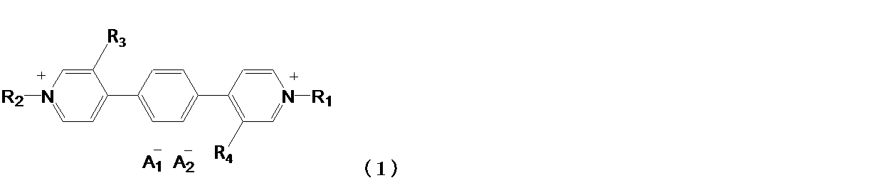
一般式(1)において、R1およびR2は、炭素原子数1以上20以下のアルキル基、アリール基、アラルキル基、およびヘテロアリール基からそれぞれ独立に選ばれる。前記炭素原子数1以上20以下のアルキル基、前記アリール基、前記アラルキル基、および前記ヘテロアリール基は置換基を有してもよい。R3およびR4は、炭素原子数1以上10以下のアルキル基、炭素原子数1以上10以下のアルコキシ基からそれぞれ独立に選ばれる。A1 -およびA2 -は、それぞれ独立に1価のアニオンを表す。 In the general formula (1), R 1 and R 2 are independently selected from an alkyl group having 1 or more and 20 or less carbon atoms, an aryl group, an aralkyl group, and a heteroaryl group, respectively. The alkyl group having 1 or more and 20 or less carbon atoms, the aryl group, the aralkyl group, and the heteroaryl group may have a substituent. R 3 and R 4 are independently selected from an alkyl group having 1 to 10 carbon atoms and an alkoxy group having 1 to 10 carbon atoms. A 1- and A 2- each independently represent a monovalent anion.
以下、前記一般式(1)で表わされる有機化合物について具体的に説明するが、本発明は、これに限定されるものではない。 Hereinafter, the organic compound represented by the general formula (1) will be specifically described, but the present invention is not limited thereto.
R1およびR2で表される炭素原子数1以上20以下のアルキル基は、直鎖状でも、分岐状でも、環状でもよい。アルキル基の水素原子はフッ素原子またはエステル基に置き換わってもよく、アルキル基中のメチル基がシアノ基に置き換わってもよい。R1およびR2で表される炭素原子数1以上20以下のアルキル基としては、例えば、メチル基、エチル基、ノルマルプロピル基、イソプロピル基、ノルマルブチル基、ターシャリーブチル基、オクチル基、シクロヘキシル基、トリフルオロメチル基等が挙げられる。 The alkyl group represented by R 1 and R 2 having 1 or more and 20 or less carbon atoms may be linear, branched, or cyclic. The hydrogen atom of the alkyl group may be replaced with a fluorine atom or an ester group, and the methyl group in the alkyl group may be replaced with a cyano group. Examples of the alkyl group represented by R 1 and R 2 having 1 or more and 20 or less carbon atoms include a methyl group, an ethyl group, a normal propyl group, an isopropyl group, a normal butyl group, a tertiary butyl group, an octyl group, and a cyclohexyl. Examples include a group, a trifluoromethyl group and the like.
R1およびR2で表される炭素原子数1以上20以下のアルキル基は、炭素原子数1以上10以下のアルコキシ基を置換基として有してよい。 The alkyl group represented by R 1 and R 2 having 1 or more and 20 or less carbon atoms may have an alkoxy group having 1 or more and 10 or less carbon atoms as a substituent.
R1およびR2で表されるアリール基は、例えば、フェニル基、ビフェニル基、ターフェニル基、フルオレニル基、ナフチル基、フルオランテニル基、アンスリル基、フェナンスリル基、ピレニル基、テトラセニル基、ペンタセニル基、トリフェニレニル基、ペリレニル基等が挙げられる。 The aryl group represented by R 1 and R 2 is, for example, a phenyl group, a biphenyl group, a terphenyl group, a fluorenyl group, a naphthyl group, a fluoranthenyl group, an anthryl group, a phenanthryl group, a pyrenyl group, a tetrasenyl group and a pentasenyl group. , Triphenylenyl group, perylenyl group and the like.
R1およびR2で表されるアラルキル基は、例えば、ベンジル基、フェネチル基等が挙げられる。
R1およびR2で表されるヘテロアリール基は、例えば、ピリジル基、ピラジル基、ピリミジル基等が挙げられる。
R1およびR2で表される基は、末端に多孔質電極へ吸着するための吸着基を有していてもよい。吸着基の具体例としては、例えば、カルボキシル基、スルホン酸基、ホスホン酸基、リン酸基、トリアルコキシシリル基等が挙げられる。
Examples of the aralkyl group represented by R 1 and R 2 include a benzyl group and a phenethyl group.
Examples of the heteroaryl group represented by R 1 and R 2 include a pyridyl group, a pyrazil group, a pyrimidyl group and the like.
The groups represented by R 1 and R 2 may have an adsorbing group at the terminal for adsorbing to the porous electrode. Specific examples of the adsorption group include a carboxyl group, a sulfonic acid group, a phosphonic acid group, a phosphoric acid group, a trialkoxysilyl group and the like.
R1およびR2で表される基が有してもよい置換基としては、フッ素、塩素、臭素、ヨウ素等のハロゲン原子;メチル基、エチル基、プロピル基、イソプロピル基、ターシャリーブチル基、シクロヘキシル基等のアルキル基(これらアルキル基の水素原子はフッ素原子に置き換わってもよい);メトキシル基、エトキシル基、プロポキシル基等のアルコキシル基;フェニル基、ビフェニル基等のアリール基;ベンジル基、フェネチル基等のアラルキル基;チエニル基、ピロリル基、ピリジル基等のヘテロアリール基;ジメチルアミノ基、ジエチルアミノ基、ジベンジルアミノ基、ジフェニルアミノ基、ジトリルアミノ基、ジアニソリルアミノ基等の置換アミノ基;フェノキシル基等のアリールオキシル基;アセチル基、ベンゾイル基等のアシル基;メチルエステル基、エチルエステル基等のエステル基;シアノ基等が挙げられる。これらのうちでも、ハロゲン原子、炭素原子数1以上4以下のアルキル基、炭素原子数1以上4以下のアルコキシ基、アリール基、アラルキル基、ヘテロアリール基が好ましい。また、R1、R2で表される基のうち、特にアリール基、アラルキル基、ヘテロアリール基がこれらの置換基を有することが好ましい。 The substituents represented by R 1 and R 2 may have halogen atoms such as fluorine, chlorine, bromine and iodine; methyl group, ethyl group, propyl group, isopropyl group, tertiary butyl group and the like. Alkyl groups such as cyclohexyl groups (hydrogen atoms of these alkyl groups may be replaced with fluorine atoms); alkoxyl groups such as methoxyl group, ethoxyl group and propoxyl group; aryl groups such as phenyl group and biphenyl group; benzyl group, Aralkyl group such as phenethyl group; heteroaryl group such as thienyl group, pyrrolyl group and pyridyl group; substituted amino group such as dimethylamino group, diethylamino group, dibenzylamino group, diphenylamino group, ditrilamino group and dianisolylamino group. An aryloxyl group such as a phenoxyl group; an acyl group such as an acetyl group and a benzoyl group; an ester group such as a methyl ester group and an ethyl ester group; a cyano group and the like can be mentioned. Among these, a halogen atom, an alkyl group having 1 or more and 4 or less carbon atoms, an alkoxy group having 1 or more and 4 or less carbon atoms, an aryl group, an aralkyl group, and a heteroaryl group are preferable. Further, among the groups represented by R 1 and R 2 , it is particularly preferable that an aryl group, an aralkyl group, and a heteroaryl group have these substituents.
A1 -およびA2 -で表される1価のアニオンは、例えば、PF6 -、ClO4 -、BF4 -、AsF6 -、SbF6 -、CF3SO3 -、(CF3SO2)2N-、およびBr-、Cl-、I-などのハロゲンイオンから選ばれる。好ましくはPF6 -、BF4 -、CF3SO3 -、(CF3SO2)2N-である。また、A1 -およびA2 -は異なるアニオンであっても同一のアニオンであってもよいが、同一のアニオンであることが好ましい。 The monovalent anions represented by A 1- and A 2- are , for example, PF 6- , ClO 4- , BF 4- , AsF 6- , SbF 6- , CF 3 SO 3- , (CF 3 SO 2 ). ) 2 N- , and selected from halogen ions such as Br- , Cl- , I-. Preferred are PF 6 − , BF 4 − , CF 3 SO 3 − , and (CF 3 SO 2 ) 2 N − . Further, A 1 − and A 2 − may be different anions or the same anion, but it is preferable that they are the same anion.
R3およびR4で表される炭素原子数1以上10以下のアルキル基は、直鎖状でも、分岐状でも、環状でもよい。アルキル基は無置換であってよい。また、アルキル基の水素原子はフッ素原子またはエステル基に置き換わってもよく、アルキル基中のメチル基がシアノ基に置き換わってもよい。具体的には、例えば、メチル基、エチル基、ノルマルプロピル基、イソプロピル基、ノルマルブチル基、ターシャリーブチル基、オクチル基、シクロヘキシル基、トリフルオロメチル基等が挙げられる。アルキル基の炭素原子数は、1以上8以下が好ましく、1以上4以下がさらに好ましい。 The alkyl group represented by R 3 and R 4 having 1 or more and 10 or less carbon atoms may be linear, branched, or cyclic. The alkyl group may be unsubstituted. Further, the hydrogen atom of the alkyl group may be replaced with a fluorine atom or an ester group, and the methyl group in the alkyl group may be replaced with a cyano group. Specific examples thereof include a methyl group, an ethyl group, a normal propyl group, an isopropyl group, a normal butyl group, a tertiary butyl group, an octyl group, a cyclohexyl group, a trifluoromethyl group and the like. The number of carbon atoms of the alkyl group is preferably 1 or more and 8 or less, and more preferably 1 or more and 4 or less.
R3およびR4で表される炭素原子数1以上10以下のアルコキシ基は、直鎖状でも、分岐状でも、環状でもよい。アルコキシ基は無置換であってよい。また、アルコキシ基の水素原子はフッ素原子に置き換わってもよい。具体的には、例えば、メトキシ基、エトキシ基、イソプロピルオキシ基、ターシャリーブチルオキシ基、オクチルオキシ基、シクロヘキシルオキシ基、トリフルオロメチルオキシ基等が挙げられる。アルコキシ基の炭素原子数は、1以上8以下が好ましく、1以上4以下がさらに好ましい。 The alkoxy group represented by R 3 and R 4 having 1 or more and 10 or less carbon atoms may be linear, branched, or cyclic. The alkoxy group may be unsubstituted. Further, the hydrogen atom of the alkoxy group may be replaced with the fluorine atom. Specific examples thereof include a methoxy group, an ethoxy group, an isopropyloxy group, a tertiary butyloxy group, an octyloxy group, a cyclohexyloxy group, a trifluoromethyloxy group and the like. The number of carbon atoms of the alkoxy group is preferably 1 or more and 8 or less, and more preferably 1 or more and 4 or less.
本発明の化合物を製造する方法については特に制限はないが、例えば、以下に示す方法によって製造することができる。
R1およびR2がアルキル基、またはアラルキル基の場合、まず、下記一般式(2)で表わされる有機化合物(中間体1)と、ハロゲン化アルキルまたはアラルキル基のアルキル部分にハロゲンを有する化合物とを所定の溶媒中で反応させ中間体1由来の塩を得る。ここで、溶媒について特に制限はないが、アセトニトリル、N,N-ジメチルホルムアミドなどの極性溶媒が好ましい。その後、得られた中間体1由来の塩と所望のアニオンを含む塩とを所定の溶媒中でアニオン交換反応させることにより、本発明の化合物を製造することができる。ここでアニオン交換反応に用いる溶媒については、中間体1由来の塩および所望のアニオンを含む塩の両方を溶解させることのできる溶媒を使用することが好ましい。
R1およびR2がアリール基の場合、中間体1と2,4-ジニトロフェニルハライドとを反応した後、所望のアリールアミンと反応させた後、所望のアニオンを含む塩と所定の溶媒中でアニオン交換反応させることにより、本発明の化合物を製造することができる。
R1およびR2がヘテロアリール基の場合、溶媒中で中間体1とハロゲン化ヘテロアリールとを反応させ中間体1由来の塩を得る。その後、得られた中間体1由来の塩と所望のアニオンを含む塩と所定の溶媒中でアニオン交換反応させることにより、本発明の化合物を製造することができる。
R1およびR2の窒素原子への導入は、用いる化合物の量、溶媒、および反応温度等を選択することによって、中間体1の2つの窒素原子のうち一方だけを反応させることもできる。中間体1の2つの窒素原子上に段階的にR1およびR2を導入することにより、中間体1の2つの窒素原子に同じR1およびR2、または互いに異なるR1およびR2を導入することも可能である。
The method for producing the compound of the present invention is not particularly limited, and for example, it can be produced by the method shown below.
When R 1 and R 2 are an alkyl group or an aralkyl group, first, an organic compound (intermediate 1) represented by the following general formula (2) and a compound having a halogen in the alkyl moiety of the alkyl halide or the aralkyl group. Is reacted in a predetermined solvent to obtain a salt derived from Intermediate 1. Here, the solvent is not particularly limited, but polar solvents such as acetonitrile and N, N-dimethylformamide are preferable. Then, the compound of the present invention can be produced by subjecting the obtained salt derived from Intermediate 1 and a salt containing a desired anion to an anion exchange reaction in a predetermined solvent. Here, as the solvent used for the anion exchange reaction, it is preferable to use a solvent capable of dissolving both the salt derived from Intermediate 1 and the salt containing a desired anion.
When R 1 and R 2 are aryl groups, the intermediate 1 is reacted with 2,4-dinitrophenyl halide, then reacted with a desired arylamine, and then in a salt containing a desired anion and a predetermined solvent. The compound of the present invention can be produced by subjecting it to an anion exchange reaction.
When R 1 and R 2 are heteroaryl groups, the intermediate 1 and the halogenated heteroaryl are reacted in a solvent to obtain a salt derived from the intermediate 1. Then, the compound of the present invention can be produced by subjecting the obtained salt derived from Intermediate 1 and a salt containing a desired anion to an anion exchange reaction in a predetermined solvent.
For the introduction of R 1 and R 2 into nitrogen atoms, only one of the two nitrogen atoms of Intermediate 1 can be reacted by selecting the amount of the compound to be used, the solvent, the reaction temperature, and the like. By introducing R 1 and R 2 stepwise onto the two nitrogen atoms of Intermediate 1, the same R 1 and R 2 or different R 1 and R 2 are introduced into the two nitrogen atoms of Intermediate 1. It is also possible to do.

中間体1の製造方法は特に制限はないが、例えば、以下に示す様に、1,4-フェニレンジボロン酸と4-クロロ-3-メチルピリジンのカップリング反応で合成することができる。 The method for producing Intermediate 1 is not particularly limited, but for example, it can be synthesized by a coupling reaction of 1,4-phenylenediboronic acid and 4-chloro-3-methylpyridine as shown below.

以下に一般式(1)で表わされる有機化合物の具体的な構造式を例示する。ただし、本発明に係る一般式(1)で表わされる有機化合物は、これらに限定されるものではない。 The specific structural formula of the organic compound represented by the general formula (1) is illustrated below. However, the organic compound represented by the general formula (1) according to the present invention is not limited thereto.


本発明に係る有機化合物は、一般式(1)で表わされる構造であり、R3およびR4の導入により中性状態において分子がねじれ構造を有する。そのため、本発明の有機化合物を溶媒に溶解させた場合であっても、本発明の有機化合物の溶液は高い透明性を有する。また、本発明に係る有機化合物は、電気化学的な酸化還元反応が可逆的に進行し、還元状態と中性状態とで光学吸収の性質(呈色状態や光透過度)が変化するEC化合物である。すなわち、本発明の有機化合物は、還元状態で着色するカソード性のEC化合物である。本発明に係る有機化合物は、還元状態(着色状態)において570nm以上、好ましくは570nm以上800nm以下の範囲に極大吸収波長を有する。このことから、本発明に係る有機化合物は、3環構造を有する従来の化合物の極大吸収波長よりも長波長側に極大吸収波長を持つ化合物である。 The organic compound according to the present invention has a structure represented by the general formula (1), and the molecule has a twisted structure in a neutral state due to the introduction of R 3 and R 4 . Therefore, even when the organic compound of the present invention is dissolved in a solvent, the solution of the organic compound of the present invention has high transparency. Further, the organic compound according to the present invention is an EC compound in which an electrochemical redox reaction proceeds reversibly and the properties of optical absorption (color development state and light transmittance) change between the reduced state and the neutral state. Is. That is, the organic compound of the present invention is a cathodic EC compound that is colored in a reduced state. The organic compound according to the present invention has a maximum absorption wavelength in the range of 570 nm or more, preferably 570 nm or more and 800 nm or less in the reduced state (colored state). From this, the organic compound according to the present invention is a compound having a maximum absorption wavelength on the longer wavelength side than the maximum absorption wavelength of the conventional compound having a three-ring structure.
≪エレクトロクロミック素子(EC素子)≫
本発明のエレクトロクロミック素子(EC素子)は、一対の電極と、一対の電極の間に配置されているエレクトロクロミック層(EC層)とを有し、EC層は、上記本発明の有機化合物を含む。以下、図面を参照しながら本実施形態に係るEC素子について説明する。
≪Electrochromic element (EC element) ≫
The electrochromic element (EC element) of the present invention has a pair of electrodes and an electrochromic layer (EC layer) arranged between the pair of electrodes, and the EC layer contains the above-mentioned organic compound of the present invention. include. Hereinafter, the EC element according to the present embodiment will be described with reference to the drawings.
図1のEC素子14は、一対の透明な電極11と、この一対の電極11の間に配置されているEC層12と、を有するEC素子14である。一対の電極11は、スペーサー13によって、電極間距離が一定となっている。このEC素子14は、一対の電極11が一対の透明な基板10の間に配置されている。EC層12は、本発明に係る有機化合物と、電解質とを有している。このEC層12は、EC化合物からなる層と、電解質からなる層とを有していてもよい。また、EC化合物と電解質とを有する溶液としてEC層12を設けてもよい。本実施形態に係るEC素子14は、EC層12が溶液であるEC素子14であることが好ましい。以下、本実施形態に係るEC素子14の構成要素について説明する。
The
<EC層12>
電解質としては、イオン解離性の塩である場合は、溶媒に対して良好な溶解性を有する化合物、また固体電解質である場合は、本発明の化合物と高い相溶性を示す化合物であれば限定されない。中でも電子供与性を有する電解質が好ましい。これら電解質は、支持電解質と呼ぶこともできる。電解質としては、例えば、各種のアルカリ金属塩、アルカリ土類金属塩などの無機イオン塩や4級アンモニウム塩や環状4級アンモニウム塩などがあげられる。具体的には、LiClO4、LiBF4、LiAsF6、LiCF3SO3、LiPF6、LiI、NaI、NaClO4、NaBF4、NaAsF6、KCl等のLi、Na、Kのアルカリ金属塩;(CH3)4NBF4、(C2H5)4NBF4、(n-C4H9)4NBF4、(n-C4H9)4NPF6、(C2H5)4NBr、(C2H5)4NClO4、(n-C4H9)4NClO4等の4級アンモニウム塩および環状4級アンモニウム塩等が挙げられる。
<
The electrolyte is not limited as long as it is an ion-dissociable salt, a compound having good solubility in a solvent, and a solid electrolyte, a compound showing high compatibility with the compound of the present invention. .. Of these, an electrolyte having an electron donating property is preferable. These electrolytes can also be called supporting electrolytes. Examples of the electrolyte include inorganic ion salts such as various alkali metal salts and alkaline earth metal salts, quaternary ammonium salts, and cyclic quaternary ammonium salts. Specifically, alkali metal salts of Li, Na, K such as LiClO 4 , LiBF 4 , LiAsF 6 , LiCF 3 SO 3 , LiPF 6 , LiI, NaI, NaClO 4 , NaBF 4 , NaAsF 6 , KCl; (CH). 3 ) 4 NBF 4 , (C 2 H 5 ) 4 NBF 4 , (n-C 4 H 9 ) 4 NBF 4 , (n-C 4 H 9 ) 4 NPF 6 , (C 2 H 5 ) 4 NBr, ( Examples thereof include quaternary ammonium salts such as C 2 H 5 ) 4 NClO 4 and (n—C 4 H 9 ) 4 NClO 4 and cyclic quaternary ammonium salts.
本発明の有機化合物および電解質を溶かす溶媒としては、これらを溶解できるものであれば特に限定されないが、特に極性を有するものが好ましい。具体的には水や、メタノール、エタノール、プロピレンカーボネート、エチレンカーボネート、ジメチルスルホキシド、ジメトキシエタン、γ-ブチロラクトン、γ-バレロラクトン、スルホラン、ジメチルホルムアミド、ジメトキシエタン、テトラヒドロフラン、アセトニトリル、プロピオンニトリル、ベンゾニトリル、ジメチルアセトアミド、メチルピロリジノン、ジオキソラン等の有機極性溶媒が挙げられる。 The solvent for dissolving the organic compound and the electrolyte of the present invention is not particularly limited as long as it can dissolve them, but a solvent having polarity is particularly preferable. Specifically, water, methanol, ethanol, propylene carbonate, ethylene carbonate, dimethyl sulfoxide, dimethoxyethane, γ-butyrolactone, γ-valerolactone, sulfolane, dimethylformamide, dimethoxyethane, tetrahydrofuran, acetonitrile, propionnitrile, benzonitrile, Examples thereof include organic polar solvents such as dimethylacetamide, methylpyrrolidinone and dioxolane.
EC層12は、さらにポリマーやゲル化剤を含有させて粘稠性が高いもの若しくはゲル状としたもの等を用いることもできる。ポリマーとしては、特に限定されず、例えばポリアクリロニトリル、カルボキシメチルセルロース、ポリ塩化ビニル、ポリエチレンオキサイド、ポリプロピレンオキサイド、ポリウレタン、ポリアクリレート、ポリメタクリレート、ポリアミド、ポリアクリルアミド、ポリエステル、ナフィオン(登録商標)などが挙げられる。
As the
本実施形態に係るEC素子は、本発明に係る有機化合物と、この有機化合物とは別種の第2の有機化合物とを有してもよい。第2の有機化合物は、一種類でも複数種種類でもよく、酸化状態で着色する化合物でも、還元状態で着色する化合物でも、その双方であってもよい。特に、酸化状態で着色する化合物が含まれていることが好ましい。酸化状態で着色する化合物とは、酸化状態における可視光の透過率が、還元状態における可視光の透過率よりも低い化合物である。 The EC element according to the present embodiment may have an organic compound according to the present invention and a second organic compound different from this organic compound. The second organic compound may be one kind or a plurality of kinds, and may be a compound colored in an oxidizing state, a compound colored in a reducing state, or both. In particular, it is preferable that a compound that is colored in an oxidized state is contained. The compound colored in the oxidized state is a compound in which the transmittance of visible light in the oxidized state is lower than the transmittance of visible light in the reduced state.
本発明に係る有機化合物は、他の色の着色材料と組み合わせることによって、EC素子として所望の色を発色することが出来る。着色時における他のEC化合物の吸収波長領域は、400nm以上800nm以下の範囲が好ましく、より好ましくは、420nm以上700nm以下である。本発明の有機化合物と他のEC化合物材料を複数組み合わせることによって、可視領域を全て吸収し、黒色着色するEC素子を作製する事もできる。 The organic compound according to the present invention can develop a desired color as an EC element by combining with a coloring material of another color. The absorption wavelength region of the other EC compound at the time of coloring is preferably in the range of 400 nm or more and 800 nm or less, and more preferably 420 nm or more and 700 nm or less. By combining a plurality of the organic compound of the present invention and other EC compound materials, it is possible to manufacture an EC element that absorbs the entire visible region and is colored black.
本発明のEC素子に用いることができる他のEC化合物として、例えば、下記の化合物があげられる。酸化状態で着色する他のEC化合物としては、5,10-ジヒドロ-5,10-ジメチルフェナジン、5,10-ジヒドロ-5,10-ジエチルフェナジンなどのフェナジン系化合物;フェロセン、テトラ-t-ブチルフェロセン、チタノセンなどのメタロセン系化合物;N,N’,N,N’-テトラメチル-p-フェニレンジアミンなどのフェニレンジアミン系化合物;1-フェニル-2-ピラゾリンなどのピラゾリン系化合物などが挙げられる。 Examples of other EC compounds that can be used in the EC element of the present invention include the following compounds. Other EC compounds that are colored in the oxidized state include phenazine compounds such as 5,10-dihydro-5,10-dimethylphenazine and 5,10-dihydro-5,10-diethylphenazine; phenylene and tetra-t-butyl. Examples thereof include metallocene compounds such as ferrocene and titanosen; phenylenediamine compounds such as N, N', N, N'-tetramethyl-p-phenylenediamine; and pyrazoline compounds such as 1-phenyl-2-pyrazolin.
還元状態で着色する化合物としては、N,N’-ジヘプチルビピリジニウムジパークロレート、N,N’-ジヘプチルビピリジニウムジテトラフフオロボレート、N,N’-ジヘプチルビピリジニウムジヘキサフルオロホスフェート、N,N’-ジエチルビピリジニウムジパークロレート、N,N’-ジエチルビピリジニウムジテトラフルオロボレート、N,N’-ジエチルビピリジニウムジヘキサフルオロホスフェート、N,N’-ジベンジルビピリジニウムジパークロレート、N,N’-ジベンジルビピリジニウムジテトラフルオロボレート、N,N’-ジベンジルビピリジニウムジヘキサフルオロホスフェート、N,N’-ジフェニルビピリジニウムジパークロレート、N,N’-ジフェニルビピリジニウムジテトラフロロボレート、N,N’-ジフェニルビピリジニウムジヘキサフロロホスフェートなどのビオロゲン系化合物;2-エチルアントラキノン、2-t-ブチルアントラキノン、オクタメチルアントラキノンなどのアントラキノン系化合物;フェロセニウムテトラフルオロボレート、フェロセニウムヘキサフルオロホスフェートなどのフェロセニウム塩系化合物;スチリル化系化合物などが挙げられる。 Examples of the compound to be colored in the reduced state include N, N'-diheptylbipyridinium diparklolate, N, N'-diheptylbipyridinium ditetrafuoloborate, N, N'-diheptylbipyridinium dihexafluorophosphate, N, N. '-Diethylbipyridinium diparklolate, N, N'-diethylbipyridinium ditetrafluoroborate, N, N'-diethylbipyridinium dihexafluorophosphate, N, N'-dibenzylbipyridinium diparklolate, N, N'-di Benzylbipyridinium ditetrafluoroborate, N, N'-dibenzylbipyridinium dihexafluorophosphate, N, N'-diphenylbipyridinium diparklolate, N, N'-diphenylbipyridinium ditetrafluoroboroborate, N, N'-diphenylbipyridinium Biorogen-based compounds such as dihexafluorophosphate; anthraquinone-based compounds such as 2-ethylanthraquinone, 2-t-butylanthraquinone, and octamethylanthraquinone; ferrosenium salt-based compounds such as ferrosenium tetrafluoroborate and ferrosenium hexafluorophosphate. ; Stylylated compounds and the like can be mentioned.
<基板10>
基板10、特に透明基板としては、例えば、無色あるいは有色ガラス、強化ガラス等が用いられる他、無色あるいは有色の透明性樹脂が用いられる。なお、本実施形態において透明とは、可視光の透過率が80%以上の透過率であることを示す。具体的には、ポリエチレンテレフタレート、ポリエチレンナフタレート、ポリノルボルネン、ポリアミド、ポリサルフォン、ポリエーテルサルフォン、ポリエーテルエーテルケトン、ポリフェニレンサルファイド、ポリカーボネート、ポリイミド、ポリメチルメタクリレート等が挙げられる。
<
As the
<電極11>
電極11、特に透明電極の材料としては、例えば、酸化インジウムスズ合金(ITO)、フッ素ドープ酸化スズ(FTO)、酸化スズ(NESA)、酸化インジウム亜鉛(IZO)、酸化銀、酸化バナジウム、酸化モリブデン、金、銀、白金、銅、インジウム、クロムなどの金属や金属酸化物、多結晶シリコン、アモルファスシリコン等のシリコン系材料、カーボンブラック、グラファイト、グラッシーカーボン等の炭素材料などを挙げることができる。また、ドーピング処理などで導電率を向上させた導電性ポリマー、例えば、ポリアニリン、ポリピロール、ポリチオフェン、ポリアセチレン、ポリパラフェニレン、ポリエチレンジオキシチオフェン(PEDOT)とポリスチレンスルホン酸の錯体なども好適に用いられる。
<
Examples of the material of the
さらに、電極11は、多孔質電極を有していてもよい。多孔質電極は表面および内部に微細孔を有した多孔質形状、ロット形状、ワイヤ形状等、表面積が大きい材料が好ましい。多孔質電極の材料は、例えば、金属、金属酸化物、カーボン等が適用できる。より好ましくは酸化チタン、酸化スズ、酸化鉄、酸化ストロンチウム、酸化タングステン、酸化亜鉛、酸化タンタル、酸化バナジウム、酸化インジウム、酸化ニッケル、酸化マンガン、酸化コバルト等の金属酸化物である。
Further, the
<スペーサー13>
スペーサー13は、一対の電極11の間に配置されており、EC層12としての本発明の有機化合物を有する溶液を収容するための空間を与えるものである。具体的には、ポリイミド、ポリテトラフルオロエチレン、ポリエステル、フッ素ゴム、エポキシ樹脂等を用いることができる。このスペーサー13により、EC素子14の電極間距離を保持することが可能である。
<
The
本実施形態に係るEC素子は、一対の電極11とスペーサー13とによって形成される液体注入口を有していてもよい。液体注入口から本発明の有機化合物を有する組成物を封入したのちに、封止部材により注入口を覆い、さらに接着剤等で密閉することでEC素子とすることができる。封止部材は、接着剤とEC性有機化合物が接触しないように隔離する役割も担っている。封止部材の形状は、特に限定されないが、楔形等の先細り形状が好ましい。
The EC element according to the present embodiment may have a liquid injection port formed by a pair of
本発明の有機化合物を有する溶液の注入方法は特に限定されず、一対の電極11の間に設けた間隙に、真空注入法、大気注入法、メニスカス法等によって予め調製した本発明の有機化合物を有する液体を注入する方法を用いることができる。
The method for injecting the solution containing the organic compound of the present invention is not particularly limited, and the organic compound of the present invention prepared in advance by a vacuum injection method, an atmospheric injection method, a meniscus method, or the like is placed in a gap provided between a pair of
≪EC素子14の用途等≫
本実施形態に係るEC素子を駆動することにより、EC素子14を通過する光の光量を調整することができ、光学フィルタ、レンズユニット、撮像装置、窓材等に用いることができる。
<< Applications of
By driving the EC element according to the present embodiment, the amount of light passing through the
<光学フィルタ>
本発明の光学フィルタは、本発明のEC素子14と、EC素子14に接続されている能動素子とを有する。本発明の光学フィルタは、周辺装置を含んでいても良い。能動素子は、EC素子14に直接接続されていても、他の素子を介して間接的に接続されていてもよい。能動素子としては、例えば、TFT素子やMIM素子等が挙げられる。本発明の光学フィルタは、能動素子が、EC素子14を駆動することにより、EC素子14を通過する光の光量を調整する。
<Optical filter>
The optical filter of the present invention has an
本発明の光学フィルタは、カメラの如き撮像装置に用いられてもよく、撮像装置に用いられる場合、撮像装置本体に設けられても、レンズユニットに設けられてもよい。以下、本発明の光学フィルタを用いて、減光(Neutral Density,ND)フィルタを構成した場合について説明する。 The optical filter of the present invention may be used in an image pickup device such as a camera, and when used in an image pickup device, it may be provided in the image pickup device main body or in a lens unit. Hereinafter, a case where a neutral density (ND) filter is configured by using the optical filter of the present invention will be described.
減光フィルタは黒色吸収を実現するフィルタであり、可視光域で均等な光吸収が必要である。有機EC化合物を用いた減光フィルタの黒色吸収の実現には、可視光域で異なる吸収域を持つ複数の材料を混合し、可視光域での吸収スペクトルを平坦なものとすればよい。有機EC化合物を混合した場合の吸収スペクトルは、各EC化合物の吸収スペクトルの和で表現されるため、適切な波長域を持つ複数のEC化合物の選択と、その濃度の調整により、減光フィルタの黒色吸収を実現することが可能である。 The dimming filter is a filter that realizes black absorption, and requires uniform light absorption in the visible light region. In order to realize black absorption of a dimming filter using an organic EC compound, a plurality of materials having different absorption regions in the visible light region may be mixed to flatten the absorption spectrum in the visible light region. Since the absorption spectrum when organic EC compounds are mixed is expressed by the sum of the absorption spectra of each EC compound, the dimming filter can be selected by selecting multiple EC compounds with appropriate wavelength ranges and adjusting their concentrations. It is possible to achieve black absorption.
本発明の光学フィルタを用いた減光フィルタの駆動例を以下に示す。一般的に減光フィルタは光量を1/2n(nは整数)とする。1/2では透過率が100%から50%になり、1/4では100%から25%になる。また、透過率を1/2にした場合、-LOG(透過率)=(吸光度)の関係から吸光度の変化量は0.3となり、1/4では0.6となる。たとえば透過率を1/2~1/64とするには、吸光度の変化量を0.3刻みで0~1.8まで制御できれば良い。 An example of driving the dimming filter using the optical filter of the present invention is shown below. Generally, the dimming filter sets the amount of light to 1/2 n (n is an integer). At 1/2, the transmittance goes from 100% to 50%, and at 1/4, it goes from 100% to 25%. Further, when the transmittance is halved, the amount of change in the absorbance is 0.3 due to the relationship of −LOG (transmittance) = (absorbance), and when it is 1/4, it is 0.6. For example, in order to set the transmittance to 1/2 to 1/64, it is sufficient that the amount of change in absorbance can be controlled from 0 to 1.8 in increments of 0.3.
EC層12が溶液である場合、ゆらぎに起因する着色量の変動分を含んでいる。正確な制御のためには光量を計測する外部モニターを光学フィルタの一部として付属させても良い。
When the
<レンズユニットおよび撮像装置>
本発明のレンズユニットは、上述した本発明の光学フィルタと、複数のレンズを有する撮像光学系とを有する。本発明のレンズユニットでは、本発明の光学フィルタを通過した光が撮像光学系を通過するように配置されていてもよいし、撮像光学系を通過した光が本発明の光学フィルタを通過するように配置されていてもよい。
<Lens unit and image pickup device>
The lens unit of the present invention includes the above-mentioned optical filter of the present invention and an imaging optical system having a plurality of lenses. In the lens unit of the present invention, the light that has passed through the optical filter of the present invention may be arranged so as to pass through the image pickup optical system, or the light that has passed through the image pickup optical system may pass through the optical filter of the present invention. It may be arranged in.
また、本発明の撮像装置は、本発明の光学フィルタと、光学フィルタを通過した光を受光する撮像素子とを有する。 Further, the image pickup apparatus of the present invention includes the optical filter of the present invention and an image pickup element that receives light that has passed through the optical filter.
図2(a)および図2(b)は、本発明の光学フィルタを用いた撮像装置を示す模式図であり、図2(a)は、本発明の光学フィルタ101を用いたレンズユニット102を有する撮像装置、図2(b)は、本発明の光学フィルタ101を有する撮像装置である。図2に示す様に、レンズユニット102はマウント部材(不図示)を介して撮像ユニット103に着脱可能に接続されている。
2 (a) and 2 (b) are schematic views showing an image pickup apparatus using the optical filter of the present invention, and FIG. 2 (a) shows a
レンズユニット102は、複数のレンズあるいはレンズ群を有するユニットである。例えば、図2(a)において、レンズユニット102は、絞りより後でフォーカシングを行うリアフォーカス式のズームレンズを表している。被写体側(紙面向かって左側)より順に正の屈折力の第1のレンズ群104、負の屈折力の第2のレンズ群105、正の屈折力の第3のレンズ群106、正の屈折力の第4のレンズ群107の4つのレンズ群を有する。第2のレンズ群105と第3のレンズ群106の間隔を変化させて変倍を行い、第4のレンズ群107の一部のレンズ群を移動させてフォーカスを行う。レンズユニット102は、例えば、第2のレンズ群105と第3のレンズ群106の間に開口絞り108を有し、また、第3のレンズ群106と第4のレンズ群107の間に本発明の光学フィルタ101を有する。レンズユニット102を通過する光は、各レンズ群104乃至107、開口絞り108および本発明の光学フィルタ101を通過するよう配置されており、開口絞り108および本発明の光学フィルタ101を用いて光量の調整を行うことができる。
The
また、レンズユニット102内の構成は適宜変更可能である。例えば、本発明の光学フィルタ101は開口絞り108の前(被写体側)あるいは後(撮像ユニット103側)に配置でき、また、第1のレンズ群104よりも前に配置しても良く、第4のレンズ群107よりも後に配置しても良い。光の収束する位置に配置すれば、本発明の光学フィルタ101の面積を小さくできるなどの利点がある。また、レンズユニット102の形態も適宜選択可能であり、リアフォーカス式の他、絞りより前でフォーカシングを行うインナーフォーカス式であっても良く、その他の方式であっても構わない。また、ズームレンズ以外にも魚眼レンズやマクロレンズなどの特殊レンズも適宜選択可能である。
Further, the configuration inside the
撮像ユニット103が有するガラスブロック109は、ローパスフィルタやフェースプレートや色フィルタ等のガラスブロックである。また、撮像素子110は、レンズユニット102を通過した光を受光するセンサ部であって、CCDやCMOS等が使用できる。また、フォトダイオードのような光センサであっても良く、光の強度あるいは波長の情報を取得し出力するものを適宜利用可能である。
The
図2(a)のように、本発明の光学フィルタ101がレンズユニット102に組み込まれている場合、駆動手段はレンズユニット102内に配置されても良く、例えば撮像ユニット103内等、レンズユニット102外に配置されても良い。レンズユニット102外に配置される場合は、配線を通してレンズユニット102内外のEC素子と駆動手段を接続し、駆動制御する。
When the
図2(b)に示す様に、撮像ユニット103が本発明の光学フィルタ101を有していても良い。本発明の光学フィルタ101は撮像ユニット103内部の適当な箇所に配置され、撮像素子110は本発明の光学フィルタ101を通過した光を受光するよう配置されていれば良い。図2(b)においては、例えば本発明の光学フィルタ101は撮像素子110の直前に配置されている。撮像ユニット103が本発明の光学フィルタ101を内蔵する場合、接続されるレンズユニット102自体が本発明の光学フィルタ101を持たなくても良いため、既存のレンズユニットを用いた調光可能な撮像装置を構成することが可能となる。
As shown in FIG. 2B, the
このような撮像装置は、光量調整と撮像素子の組合せを有する製品に適用可能である。例えばカメラ、デジタルカメラ、ビデオカメラ、デジタルビデオカメラに使用可能であり、また、携帯電話やスマートフォン、PC、タブレットなど撮像装置を内蔵する製品にも適用できる。 Such an image pickup device can be applied to a product having a combination of light intensity adjustment and an image pickup element. For example, it can be used for cameras, digital cameras, video cameras, and digital video cameras, and can also be applied to products having a built-in image pickup device such as mobile phones, smartphones, PCs, and tablets.
本発明の光学フィルタ101を調光部材として用いることで、調光量を一つのフィルタで適宜可変させることが可能となり、部材点数の削減や省スペース化といった利点がある。
By using the
<窓材>
本発明の窓材は、本発明のEC素子14を有する。本発明の窓材は、EC素子14を駆動する駆動手段を有することが好ましい。図3は、本発明の窓材を示す図であり、図3(a)は斜視図、図3(b)は図3(a)のX-X’断面図である。
<Window material>
The window material of the present invention has the
図3の窓材111は調光窓であり、EC素子14と、それを挟持する透明板113と、全体を囲繞して一体化するフレーム112とから成る。駆動手段はフレーム112内に一体化されていても良く、フレーム112外に配置され配線を通してEC素子14と接続されていても良い。
The
透明板113は光透過率が高い材料であれば特に限定されず、窓としての利用を考慮すればガラス素材であることが好ましい。図8において、EC素子14は透明板113と独立した構成部材であるが、例えば、EC素子14の基板10を透明板113としても構わない。
The
フレーム112は材質を問わないが、EC素子14の少なくとも一部を被覆し、一体化された形態を有するもの全般をフレームとして構わない。
The
係る調光窓は、例えば日中の太陽光の室内への入射量を調整する用途に適用できる。太陽の光量の他、熱量の調整にも適用できるため、室内の明るさや温度の制御に使用することが可能である。また、シャッターとして、室外から室内への眺望を遮断する用途にも適用可能である。このような調光窓は、建造物用のガラス窓の他に、自動車や電車、飛行機、船など乗り物の窓、時計や携帯電話の表示面のフィルタにも適用可能である。 Such a dimming window can be applied to, for example, an application for adjusting the amount of sunlight incident into a room during the daytime. Since it can be applied to adjust the amount of heat as well as the amount of sunlight, it can be used to control the brightness and temperature of the room. It can also be applied as a shutter to block the view from the outside to the inside. Such dimming windows can be applied not only to glass windows for buildings, but also to windows of vehicles such as automobiles, trains, airplanes, and ships, and filters on the display surface of clocks and mobile phones.
以下、実施例について説明していくが、本発明は以下の実施例に限定されるものではない。 Hereinafter, examples will be described, but the present invention is not limited to the following examples.
<実施例1(例示化合物A-1の合成)>
(1)中間体1の合成
<Example 1 (Synthesis of Exemplified Compound A-1)>
(1) Synthesis of intermediate 1
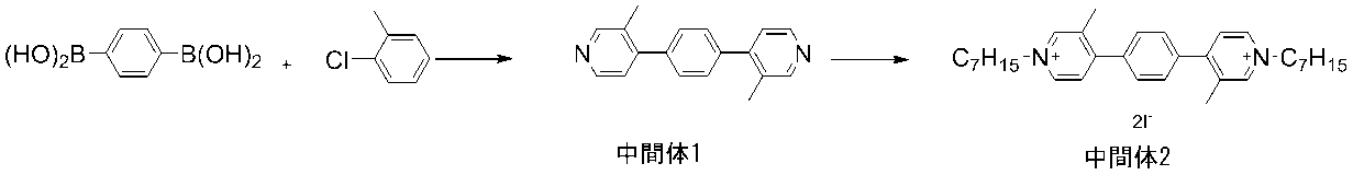
まず、中間体1を合成した。反応容器に、1,4-フェニレンジボロン酸(0.20g、1.2mmol)と4-クロロ-3-メチルピリジン(0.46g、3.6mmol)、テトラキス(トリフェニルホスフィン)パラジウム(0.07g、0.06mmol)、リン酸三カリウム(0.77g、3.6mmol)、ジオキサン(30ml)、及び水(10ml)を仕込み、窒素気流下、8時間加熱還流で撹拌を行った。反応終了後、反応液を濃縮した後、クロロホルムで抽出を行った。有機層を水洗し、硫酸マグネシウムで乾燥後に減圧乾固を行った。シリカゲルカラムクロマト(溶離液:クロロホルム/ヘキサン=4/1)で精製し、中間体1を0.1g(収率:32%)得た。1H NMR測定により、中間体1の構造を確認した。
1H NMR(DMSO-d6,500MHz) σ(ppm):8.51(s,2H),8.45(t,2H),7.52(m,4H),7.30(m,2H),2.29(s,6H).
First, Intermediate 1 was synthesized. In the reaction vessel, 1,4-phenylenediboronic acid (0.20 g, 1.2 mmol), 4-chloro-3-methylpyridine (0.46 g, 3.6 mmol), tetrakis (triphenylphosphine) palladium (0. 07 g, 0.06 mmol), tripotassium phosphate (0.77 g, 3.6 mmol), dioxane (30 ml), and water (10 ml) were charged, and the mixture was stirred by heating and refluxing for 8 hours under a nitrogen stream. After completion of the reaction, the reaction solution was concentrated and then extracted with chloroform. The organic layer was washed with water, dried over magnesium sulfate, and then dried under reduced pressure. Purification by silica gel column chromatography (eluent: chloroform / hexane = 4/1) gave 0.1 g (yield: 32%) of Intermediate 1. 1 The structure of Intermediate 1 was confirmed by 1 H NMR measurement.
1 1 H NMR (DMSO-d 6,500 MHz) σ (ppm): 8.51 (s, 2H), 8.45 (t, 2H), 7.52 (m, 4H), 7.30 (m, 2H) , 2.29 (s, 6H).
(2)中間体2の合成
次に、中間体1を用いて中間体2の合成をおこなった。反応容器に、中間体1(0.100g、0.38mmol)、1-ヨードヘプタン(0.347g、1.53mmol)、N,N-ジメチルホルムアミド10mlを仕込み、窒素気流下、10時間加熱還流で撹拌を行った。反応終了後、反応液を酢酸エチルに滴下し生じた沈殿物を酢酸エチルで洗浄し中間体2を0.219g(収率:80%)得た。1H NMR測定により、中間体2の構造を確認した。
1H NMR(DMSO-d6,500MHz) σ(ppm):9.15(s,2H),9.02(d,2H),8.11(d,2H),7.80(m,4H),4.59(t,4H),1.95(t,4H),2.54(s,6H),1.30(m,16H),0.85(t,6H).
(2) Synthesis of Intermediate 2 Next, Intermediate 2 was synthesized using Intermediate 1. Intermediate 1 (0.100 g, 0.38 mmol), 1-iodoheptan (0.347 g, 1.53 mmol) and 10 ml of N, N-dimethylformamide were charged in a reaction vessel, and heated under reflux for 10 hours under a nitrogen stream. Stirring was performed. After completion of the reaction, the reaction solution was added dropwise to ethyl acetate, and the resulting precipitate was washed with ethyl acetate to obtain 0.219 g (yield: 80%) of Intermediate 2. 1 The structure of Intermediate 2 was confirmed by 1 H NMR measurement.
1 1 H NMR (DMSO-d 6,500 MHz) σ (ppm): 9.15 (s, 2H), 9.02 (d, 2H), 8.11 (d, 2H), 7.80 (m, 4H) , 4.59 (t, 4H), 1.95 (t, 4H), 2.54 (s, 6H), 1.30 (m, 16H), 0.85 (t, 6H).
(3)例示化合物A-1の合成
次に、中間体2を用いて例示化合物A-1の合成をおこなった。まず、中間体2(0.219g、0.31mmol)を水に溶解した。ヘキサフルオロリン酸アンモニウム水溶液を滴下し、室温で3時間撹拌を行った。析出した結晶をろ過、イソプロピルアルコール、ジエチルエーテルで順次洗浄し、例示化合物A-1を0.207g(収率:90%)得た。1H NMR測定により、例示化合物A-1の構造を確認した。
1H NMR(DMSO-d6,500MHz) σ(ppm):9.15(s,2H),9.00(m,2H),8.12(m,2H),7.80(m,4H),4.58(t,4H),1.95(t,4H),2.54(s,6H),1.30(m,16H),0.86(t,6H).
(3) Synthesis of Exemplified Compound A-1 Next, Exemplified Compound A-1 was synthesized using Intermediate 2. First, Intermediate 2 (0.219 g, 0.31 mmol) was dissolved in water. An aqueous solution of ammonium hexafluorophosphate was added dropwise, and the mixture was stirred at room temperature for 3 hours. The precipitated crystals were filtered, washed successively with isopropyl alcohol and diethyl ether to obtain 0.207 g (yield: 90%) of Exemplified Compound A-1. 1 The structure of Exemplified Compound A-1 was confirmed by 1 H NMR measurement.
1 1 H NMR (DMSO-d 6,500 MHz) σ (ppm): 9.15 (s, 2H), 9.00 (m, 2H), 8.12 (m, 2H), 7.80 (m, 4H) , 4.58 (t, 4H), 1.95 (t, 4H), 2.54 (s, 6H), 1.30 (m, 16H), 0.86 (t, 6H).
<実施例2>
例示化合物A-1を用いて図1に示すEC素子14を作製し、その特性評価を行った。電解質としての過塩素酸テトラブチルアンモニウムを0.1Mの濃度でプロピレンカーボネート(炭酸プロピレン)に溶解させ、次いで例示化合物A-1を40.0mMの濃度で溶解させることにより、EC層12を形成するEC媒体を得た。
<Example 2>
The
EC素子14の基板10、電極11として、透明導電膜(透明電極膜)付きのガラス基板を用いた。一対の透明導電膜(ITO)付きのガラス基板の四方の端部に絶縁層(SiO2)を形成した。基板間隔を規定するスペーサー13としてのPETフィルム(帝人デュポンフィルム社製メリネックス(登録商標)S、125μm厚)を、一対の透明電極膜付きガラス基板の間に配置する。その後、EC媒体注入用の注入口を残して、エポキシ系接着剤によりガラス基板とPETフィルムとを接着し、封止した。以上のように、注入口付き空セルを作製した。
As the
次に注入口より、例示化合物A-1を含むEC媒体を真空注入法により注入後、注入口をエポキシ系接着剤により封止し、EC素子とした。 Next, an EC medium containing the exemplary compound A-1 was injected from the injection port by a vacuum injection method, and then the injection port was sealed with an epoxy adhesive to obtain an EC element.
本実施例のEC素子に、1.5Vの電圧を印加すると、EC素子に含まれる例示化合物A-1の還元種に由来する着色を示した。さらに、-0.5Vの電圧を印加すると、EC素子は消色した。すなわち、本実施例のEC素子は、着色状態と消色状態とを可逆的に変化でき、EC性を有する。図4に、本実施例のEC素子の着色状態及び消色状態における紫外可視吸収スペクトルを示した。例示化合物A-1は還元状態において、570nmに極大吸収波長を有する。 When a voltage of 1.5 V was applied to the EC device of this example, coloring derived from the reduced species of Exemplified Compound A-1 contained in the EC device was shown. Further, when a voltage of −0.5 V was applied, the EC element was decolorized. That is, the EC element of this embodiment can reversibly change between the colored state and the decolorized state, and has an EC property. FIG. 4 shows an ultraviolet-visible absorption spectrum in the colored state and the decolorized state of the EC element of this example. Exemplified compound A-1 has a maximum absorption wavelength at 570 nm in the reduced state.
<比較例1>
下記の構造で表わされる5環構造を有する比較化合物1を用いてEC素子を作製し、還元状態における吸収波長を測定した。
<Comparative Example 1>
An EC device was manufactured using the comparative compound 1 having a five-ring structure represented by the following structure, and the absorption wavelength in the reduced state was measured.

例示化合物A-1の代わりに比較化合物を用いた以外は、実施例2と同様の方法で評価を行った。図5に、本比較例のEC素子の着色状態および消色状態における紫外可視吸収スペクトルを示した。比較化合物は、還元状態において550nmに極大吸収波長を有する。このことから、比較化合物は両端にピリミジル基を有するため還元状態において吸収波長が通常の5員環化合物から予想される吸収波長よりもレッドシフトしたが、例示化合物A-1よりも短波長域に吸収波長を有することがわかった。 The evaluation was carried out in the same manner as in Example 2 except that the comparative compound was used instead of the exemplary compound A-1. FIG. 5 shows an ultraviolet-visible absorption spectrum in the colored state and the decolorized state of the EC element of this comparative example. The comparative compound has a maximum absorption wavelength at 550 nm in the reduced state. From this, since the comparative compound has pyrimidyl groups at both ends, the absorption wavelength was red-shifted from the absorption wavelength expected from the normal 5-membered ring compound in the reduced state, but it was in the shorter wavelength region than the exemplary compound A-1. It was found to have an absorption wavelength.
以上のように、本発明の有機化合物によれば、ねじれ構造を導入することで、ねじれ構造を持たない3環構造を有する化合物、5環構造を有する化合物よりも還元状態の吸収波長を長波長化できる材料を提供できる。 As described above, according to the organic compound of the present invention, by introducing the twisted structure, the absorption wavelength in the reduced state is longer than that of the compound having a three-ring structure having no twisted structure and the compound having a five-ring structure. We can provide materials that can be converted.
10:基板、11:電極、12:EC層、13:スペーサー、14:EC素子 10: Substrate, 11: Electrode, 12: EC layer, 13: Spacer, 14: EC element
Claims (18)

R3およびR4は、炭素原子数1以上10以下のアルキル基からそれぞれ独立に選ばれる。
A1 -およびA2 -は、それぞれ独立に1価のアニオンを表す。 An organic compound represented by the following general formula (1).
R 3 and R 4 are independently selected from alkyl groups having 1 or more and 10 or less carbon atoms.
A 1- and A 2- each independently represent a monovalent anion.
前記一対の電極の間に配置されているエレクトロクロミック層と、を有し、
前記エレクトロクロミック層は、請求項1乃至9のいずれか一項に記載の有機化合物を含むことを特徴とするエレクトロクロミック素子。 With a pair of electrodes,
With an electrochromic layer disposed between the pair of electrodes,
The electrochromic element is characterized by containing the organic compound according to any one of claims 1 to 9 .
Applications Claiming Priority (2)
| Application Number | Priority Date | Filing Date | Title |
|---|---|---|---|
| JP2017028821 | 2017-02-20 | ||
| JP2017028821 | 2017-02-20 |
Publications (2)
| Publication Number | Publication Date |
|---|---|
| JP2018135327A JP2018135327A (en) | 2018-08-30 |
| JP7030552B2 true JP7030552B2 (en) | 2022-03-07 |
Family
ID=63166959
Family Applications (1)
| Application Number | Title | Priority Date | Filing Date |
|---|---|---|---|
| JP2018022090A Active JP7030552B2 (en) | 2017-02-20 | 2018-02-09 | Organic compounds, electrochromic elements, optical filters, lens units, image pickup devices and window materials |
Country Status (2)
| Country | Link |
|---|---|
| US (1) | US10364223B2 (en) |
| JP (1) | JP7030552B2 (en) |
Families Citing this family (3)
| Publication number | Priority date | Publication date | Assignee | Title |
|---|---|---|---|---|
| US10310350B2 (en) * | 2016-05-12 | 2019-06-04 | Canon Kabushiki Kaisha | Organic compound, electrochromic compound, and electrochromic element, optical filter, lens unit, imaging device, and window component having same |
| JP7446719B2 (en) * | 2018-06-28 | 2024-03-11 | キヤノン株式会社 | Organic compounds and electrochromic devices containing them, optical filters, lens units, imaging devices and windows |
| US12486447B2 (en) * | 2021-04-21 | 2025-12-02 | Wuxi Bozhi Huachuang Science And Technology Co., Ltd. | Systems and methods for electrochromic molecules |
Citations (7)
| Publication number | Priority date | Publication date | Assignee | Title |
|---|---|---|---|---|
| JP2007171781A (en) | 2005-12-26 | 2007-07-05 | Sony Corp | Electrochromic device |
| JP2007304164A (en) | 2006-05-09 | 2007-11-22 | Sony Corp | Electrochromic device |
| JP2008089705A (en) | 2006-09-29 | 2008-04-17 | Sony Corp | Electrochromic device |
| CN103059831A (en) | 2012-11-14 | 2013-04-24 | 仝泽彬 | Electrochromic material and electrochromic device |
| JP2015124228A (en) | 2013-12-25 | 2015-07-06 | 株式会社リコー | Electrochromic compound, electrochromic composition, display device using the same, and light control device |
| JP2016155802A (en) | 2015-02-20 | 2016-09-01 | キヤノン株式会社 | Organic compound, electrochromic element having the same, optical filter, lens unit, imaging device, and window material |
| WO2017005824A1 (en) | 2015-07-08 | 2017-01-12 | Essilor International (Compagnie Generale D'optique) | Electrochromic compounds and optical articles containing them |
Family Cites Families (12)
| Publication number | Priority date | Publication date | Assignee | Title |
|---|---|---|---|---|
| JPS61148162A (en) * | 1984-12-20 | 1986-07-05 | Nippon Sheet Glass Co Ltd | Viologen derivative |
| KR101032036B1 (en) * | 2003-04-30 | 2011-05-02 | 쇼와 덴코 가부시키가이샤 | Organic polymer light emitting device material and organic polymer light emitting device |
| JP5006059B2 (en) * | 2007-01-29 | 2012-08-22 | エリック エム. カレイラ | Chiral iridium aqua complex and method for producing optically active hydroxy compound using the same |
| KR101342326B1 (en) * | 2008-04-11 | 2013-12-16 | 닛뽕소다 가부시키가이샤 | Optically active dibenzazepine derivatives |
| JP5949012B2 (en) | 2012-03-21 | 2016-07-06 | 株式会社リコー | Electrochromic compound, electrochromic composition, and display element |
| JP6728628B2 (en) * | 2015-03-13 | 2020-07-22 | 株式会社リコー | Electrochromic compound, electrochromic composition, and electrochromic device and electrochromic dimming device |
| US9766527B2 (en) | 2015-07-02 | 2017-09-19 | Canon Kabushiki Kaisha | Electrochromic element, optical filter, lens unit, image pickup apparatus, and window member |
| US9869919B2 (en) | 2015-07-02 | 2018-01-16 | Canon Kabushiki Kaisha | Electrochromic element, optical filter, lens unit, image pickup apparatus, and window member |
| JP6812135B2 (en) | 2015-07-10 | 2021-01-13 | キヤノン株式会社 | Electrochromic element |
| WO2017104283A1 (en) * | 2015-12-17 | 2017-06-22 | 富士フイルム株式会社 | Near-infrared absorbent composition, membrane, infrared cut filter, solid-state imaging element, infrared absorbent, and compound |
| US9954187B2 (en) * | 2016-04-08 | 2018-04-24 | Idemitsu Kosan Co., Ltd. | Compound, organic electroluminescence device and electronic device |
| US10310350B2 (en) * | 2016-05-12 | 2019-06-04 | Canon Kabushiki Kaisha | Organic compound, electrochromic compound, and electrochromic element, optical filter, lens unit, imaging device, and window component having same |
-
2018
- 2018-02-09 JP JP2018022090A patent/JP7030552B2/en active Active
- 2018-02-13 US US15/895,056 patent/US10364223B2/en active Active
Patent Citations (7)
| Publication number | Priority date | Publication date | Assignee | Title |
|---|---|---|---|---|
| JP2007171781A (en) | 2005-12-26 | 2007-07-05 | Sony Corp | Electrochromic device |
| JP2007304164A (en) | 2006-05-09 | 2007-11-22 | Sony Corp | Electrochromic device |
| JP2008089705A (en) | 2006-09-29 | 2008-04-17 | Sony Corp | Electrochromic device |
| CN103059831A (en) | 2012-11-14 | 2013-04-24 | 仝泽彬 | Electrochromic material and electrochromic device |
| JP2015124228A (en) | 2013-12-25 | 2015-07-06 | 株式会社リコー | Electrochromic compound, electrochromic composition, display device using the same, and light control device |
| JP2016155802A (en) | 2015-02-20 | 2016-09-01 | キヤノン株式会社 | Organic compound, electrochromic element having the same, optical filter, lens unit, imaging device, and window material |
| WO2017005824A1 (en) | 2015-07-08 | 2017-01-12 | Essilor International (Compagnie Generale D'optique) | Electrochromic compounds and optical articles containing them |
Non-Patent Citations (1)
| Title |
|---|
| Bar, Galit 他,RGB organic electrochromic cells,Solar Energy Materials & Solar Cells ,2012年,99,,123-128 |
Also Published As
| Publication number | Publication date |
|---|---|
| US20180237393A1 (en) | 2018-08-23 |
| US10364223B2 (en) | 2019-07-30 |
| JP2018135327A (en) | 2018-08-30 |
Similar Documents
| Publication | Publication Date | Title |
|---|---|---|
| JP6900202B2 (en) | Organic compounds, electrochromic elements, electrochromic devices, optical filters, imaging devices, lens units and window materials | |
| JP6812135B2 (en) | Electrochromic element | |
| US9701671B2 (en) | Organic compound, electrochromic element containing the same, optical filter, lens unit, imaging device, and window component | |
| JP6598693B2 (en) | Organic compound, electrochromic element having the same, optical filter, lens unit, imaging device, window material | |
| WO2017154681A1 (en) | Organic compound, electrochromic element, electrochromic device, optical filter, imaging device, lens unit, and window material | |
| JP2018024624A (en) | Organic compound and electrochromic element, optical film, lens unit and imaging device having the same | |
| US10310350B2 (en) | Organic compound, electrochromic compound, and electrochromic element, optical filter, lens unit, imaging device, and window component having same | |
| JP7030552B2 (en) | Organic compounds, electrochromic elements, optical filters, lens units, image pickup devices and window materials | |
| JP6429575B2 (en) | Novel organic compound and electrochromic device having the same | |
| JP7541863B2 (en) | Organic compounds and electrochromic devices | |
| US10907091B2 (en) | Organic compound and electrochromic element | |
| JP6991731B2 (en) | Organic compounds, electrochromic compounds, and electrochromic elements having them, optical filters, lens units, image pickup devices, window materials | |
| JP2017197477A (en) | Organic compound, and electrochromic element, optical filter, lens unit, imaging device, and window material having the same | |
| JP7166939B2 (en) | Organic compounds and electrochromic devices | |
| US20240294490A1 (en) | Organic compound and electrochromic element | |
| JP7446719B2 (en) | Organic compounds and electrochromic devices containing them, optical filters, lens units, imaging devices and windows | |
| JP7030632B2 (en) | Organic compounds, electrochromic elements, optical filters, image pickup devices, windows and electrochromic mirrors | |
| US20230416222A1 (en) | Organic compound and electrochromic element | |
| JP7604173B2 (en) | Organic compound, electrochromic element, optical filter, lens unit, imaging device, and window | |
| US20250189854A1 (en) | Organic compound and electrochromic element | |
| JP2021109862A (en) | Organic compounds and electrochromic devices | |
| JP6921590B2 (en) | Organic compounds, electrochromic elements containing them, optical filters, lens units, imaging devices, window materials | |
| JP2025093841A (en) | Organic Compounds and Electrochromic Devices | |
| JP2021011441A (en) | Organic compounds, electrochromic elements containing them, optical films, lens units, image pickup devices, window materials | |
| WO2020004085A1 (en) | Organic compound, and electrochromic element, optical filter, lens unit, imaging element, and window having said organic compound |
Legal Events
| Date | Code | Title | Description |
|---|---|---|---|
| A621 | Written request for application examination |
Free format text: JAPANESE INTERMEDIATE CODE: A621 Effective date: 20210204 |
|
| A977 | Report on retrieval |
Free format text: JAPANESE INTERMEDIATE CODE: A971007 Effective date: 20211021 |
|
| A131 | Notification of reasons for refusal |
Free format text: JAPANESE INTERMEDIATE CODE: A131 Effective date: 20211102 |
|
| A521 | Request for written amendment filed |
Free format text: JAPANESE INTERMEDIATE CODE: A523 Effective date: 20211223 |
|
| TRDD | Decision of grant or rejection written | ||
| A01 | Written decision to grant a patent or to grant a registration (utility model) |
Free format text: JAPANESE INTERMEDIATE CODE: A01 Effective date: 20220125 |
|
| A61 | First payment of annual fees (during grant procedure) |
Free format text: JAPANESE INTERMEDIATE CODE: A61 Effective date: 20220222 |
|
| R151 | Written notification of patent or utility model registration |
Ref document number: 7030552 Country of ref document: JP Free format text: JAPANESE INTERMEDIATE CODE: R151 |