US10364223B2 - Organic compound, electrochromic element, optical filter, lens unit, image pickup apparatus, and window member - Google Patents
Organic compound, electrochromic element, optical filter, lens unit, image pickup apparatus, and window member Download PDFInfo
- Publication number
- US10364223B2 US10364223B2 US15/895,056 US201815895056A US10364223B2 US 10364223 B2 US10364223 B2 US 10364223B2 US 201815895056 A US201815895056 A US 201815895056A US 10364223 B2 US10364223 B2 US 10364223B2
- Authority
- US
- United States
- Prior art keywords
- group
- organic compound
- optical filter
- image pickup
- present
- Prior art date
- Legal status (The legal status is an assumption and is not a legal conclusion. Google has not performed a legal analysis and makes no representation as to the accuracy of the status listed.)
- Active, expires
Links
- 150000002894 organic compounds Chemical class 0.000 title claims abstract description 53
- 230000003287 optical effect Effects 0.000 title claims description 49
- 125000000217 alkyl group Chemical group 0.000 claims abstract description 34
- 125000004432 carbon atom Chemical group C* 0.000 claims abstract description 26
- 125000003118 aryl group Chemical group 0.000 claims abstract description 16
- 125000003710 aryl alkyl group Chemical group 0.000 claims abstract description 15
- 125000003545 alkoxy group Chemical group 0.000 claims abstract description 14
- 125000001072 heteroaryl group Chemical group 0.000 claims abstract description 14
- 150000001450 anions Chemical class 0.000 claims abstract description 12
- 150000001875 compounds Chemical class 0.000 claims description 74
- 238000010521 absorption reaction Methods 0.000 claims description 26
- 239000003792 electrolyte Substances 0.000 claims description 17
- 125000001424 substituent group Chemical group 0.000 claims description 7
- 125000005843 halogen group Chemical group 0.000 claims description 3
- 239000007788 liquid Substances 0.000 claims description 3
- GEYOCULIXLDCMW-UHFFFAOYSA-N 1,2-phenylenediamine Chemical compound NC1=CC=CC=C1N GEYOCULIXLDCMW-UHFFFAOYSA-N 0.000 claims description 2
- VEPOHXYIFQMVHW-XOZOLZJESA-N 2,3-dihydroxybutanedioic acid (2S,3S)-3,4-dimethyl-2-phenylmorpholine Chemical compound OC(C(O)C(O)=O)C(O)=O.C[C@H]1[C@@H](OCCN1C)c1ccccc1 VEPOHXYIFQMVHW-XOZOLZJESA-N 0.000 claims description 2
- PCNDJXKNXGMECE-UHFFFAOYSA-N Phenazine Natural products C1=CC=CC2=NC3=CC=CC=C3N=C21 PCNDJXKNXGMECE-UHFFFAOYSA-N 0.000 claims description 2
- DNXIASIHZYFFRO-UHFFFAOYSA-N pyrazoline Chemical compound C1CN=NC1 DNXIASIHZYFFRO-UHFFFAOYSA-N 0.000 claims description 2
- -1 oligothiophene Chemical class 0.000 description 28
- 239000000463 material Substances 0.000 description 20
- 239000010410 layer Substances 0.000 description 16
- 239000002904 solvent Substances 0.000 description 15
- 229910052757 nitrogen Inorganic materials 0.000 description 14
- 238000002834 transmittance Methods 0.000 description 14
- 238000000034 method Methods 0.000 description 13
- 238000002347 injection Methods 0.000 description 11
- 239000007924 injection Substances 0.000 description 11
- 230000007935 neutral effect Effects 0.000 description 11
- 150000003839 salts Chemical class 0.000 description 11
- 239000000243 solution Substances 0.000 description 11
- 239000000758 substrate Substances 0.000 description 11
- 238000006243 chemical reaction Methods 0.000 description 10
- ZMXDDKWLCZADIW-UHFFFAOYSA-N N,N-Dimethylformamide Chemical compound CN(C)C=O ZMXDDKWLCZADIW-UHFFFAOYSA-N 0.000 description 9
- 238000004040 coloring Methods 0.000 description 9
- 239000011521 glass Substances 0.000 description 9
- 238000000862 absorption spectrum Methods 0.000 description 7
- 230000000052 comparative effect Effects 0.000 description 7
- 125000002496 methyl group Chemical group [H]C([H])([H])* 0.000 description 7
- 238000005160 1H NMR spectroscopy Methods 0.000 description 6
- WEVYAHXRMPXWCK-UHFFFAOYSA-N Acetonitrile Chemical compound CC#N WEVYAHXRMPXWCK-UHFFFAOYSA-N 0.000 description 6
- IAZDPXIOMUYVGZ-WFGJKAKNSA-N Dimethyl sulfoxide Chemical compound [2H]C([2H])([2H])S(=O)C([2H])([2H])[2H] IAZDPXIOMUYVGZ-WFGJKAKNSA-N 0.000 description 6
- XEKOWRVHYACXOJ-UHFFFAOYSA-N Ethyl acetate Chemical compound CCOC(C)=O XEKOWRVHYACXOJ-UHFFFAOYSA-N 0.000 description 6
- 238000002835 absorbance Methods 0.000 description 6
- 125000006850 spacer group Chemical group 0.000 description 6
- 0 C.C.[1*]N1=CC([4*])=C(C2=CC=C(C3=CC=N([2*])C=C3[3*])C=C2)C=C1 Chemical compound C.C.[1*]N1=CC([4*])=C(C2=CC=C(C3=CC=N([2*])C=C3[3*])C=C2)C=C1 0.000 description 5
- 239000000853 adhesive Substances 0.000 description 5
- 230000001070 adhesive effect Effects 0.000 description 5
- 230000008859 change Effects 0.000 description 5
- 229910052731 fluorine Inorganic materials 0.000 description 5
- IJGRMHOSHXDMSA-UHFFFAOYSA-N Atomic nitrogen Chemical compound N#N IJGRMHOSHXDMSA-UHFFFAOYSA-N 0.000 description 4
- HEDRZPFGACZZDS-UHFFFAOYSA-N Chloroform Chemical compound ClC(Cl)Cl HEDRZPFGACZZDS-UHFFFAOYSA-N 0.000 description 4
- 238000005349 anion exchange Methods 0.000 description 4
- 230000015572 biosynthetic process Effects 0.000 description 4
- 229940125904 compound 1 Drugs 0.000 description 4
- 229920001940 conductive polymer Polymers 0.000 description 4
- 125000000113 cyclohexyl group Chemical group [H]C1([H])C([H])([H])C([H])([H])C([H])(*)C([H])([H])C1([H])[H] 0.000 description 4
- 125000001153 fluoro group Chemical group F* 0.000 description 4
- 125000004435 hydrogen atom Chemical group [H]* 0.000 description 4
- 125000004433 nitrogen atom Chemical group N* 0.000 description 4
- 238000007789 sealing Methods 0.000 description 4
- 150000003384 small molecules Chemical class 0.000 description 4
- 238000003786 synthesis reaction Methods 0.000 description 4
- XLYOFNOQVPJJNP-UHFFFAOYSA-N water Substances O XLYOFNOQVPJJNP-UHFFFAOYSA-N 0.000 description 4
- WPWHSFAFEBZWBB-UHFFFAOYSA-N 1-butyl radical Chemical compound [CH2]CCC WPWHSFAFEBZWBB-UHFFFAOYSA-N 0.000 description 3
- MWVTWFVJZLCBMC-UHFFFAOYSA-N 4,4'-bipyridine Chemical compound C1=NC=CC(C=2C=CN=CC=2)=C1 MWVTWFVJZLCBMC-UHFFFAOYSA-N 0.000 description 3
- RTZKZFJDLAIYFH-UHFFFAOYSA-N Diethyl ether Chemical compound CCOCC RTZKZFJDLAIYFH-UHFFFAOYSA-N 0.000 description 3
- LFQSCWFLJHTTHZ-UHFFFAOYSA-N Ethanol Chemical compound CCO LFQSCWFLJHTTHZ-UHFFFAOYSA-N 0.000 description 3
- KFZMGEQAYNKOFK-UHFFFAOYSA-N Isopropanol Chemical compound CC(C)O KFZMGEQAYNKOFK-UHFFFAOYSA-N 0.000 description 3
- OKKJLVBELUTLKV-UHFFFAOYSA-N Methanol Chemical compound OC OKKJLVBELUTLKV-UHFFFAOYSA-N 0.000 description 3
- 229910019785 NBF4 Inorganic materials 0.000 description 3
- JUJWROOIHBZHMG-UHFFFAOYSA-N Pyridine Chemical group C1=CC=NC=C1 JUJWROOIHBZHMG-UHFFFAOYSA-N 0.000 description 3
- 230000008901 benefit Effects 0.000 description 3
- JFDZBHWFFUWGJE-UHFFFAOYSA-N benzonitrile Chemical compound N#CC1=CC=CC=C1 JFDZBHWFFUWGJE-UHFFFAOYSA-N 0.000 description 3
- 239000004305 biphenyl Substances 0.000 description 3
- 238000004061 bleaching Methods 0.000 description 3
- 125000004093 cyano group Chemical group *C#N 0.000 description 3
- 125000004122 cyclic group Chemical group 0.000 description 3
- BOXSCYUXSBYGRD-UHFFFAOYSA-N cyclopenta-1,3-diene;iron(3+) Chemical class [Fe+3].C=1C=C[CH-]C=1.C=1C=C[CH-]C=1 BOXSCYUXSBYGRD-UHFFFAOYSA-N 0.000 description 3
- 125000001495 ethyl group Chemical group [H]C([H])([H])C([H])([H])* 0.000 description 3
- 125000001449 isopropyl group Chemical group [H]C([H])([H])C([H])(*)C([H])([H])[H] 0.000 description 3
- 238000005259 measurement Methods 0.000 description 3
- 229910044991 metal oxide Inorganic materials 0.000 description 3
- 150000004706 metal oxides Chemical class 0.000 description 3
- VLKZOEOYAKHREP-UHFFFAOYSA-N n-Hexane Chemical compound CCCCCC VLKZOEOYAKHREP-UHFFFAOYSA-N 0.000 description 3
- 238000006479 redox reaction Methods 0.000 description 3
- 125000000999 tert-butyl group Chemical group [H]C([H])([H])C(*)(C([H])([H])[H])C([H])([H])[H] 0.000 description 3
- XOLBLPGZBRYERU-UHFFFAOYSA-N tin dioxide Chemical compound O=[Sn]=O XOLBLPGZBRYERU-UHFFFAOYSA-N 0.000 description 3
- 229910001887 tin oxide Inorganic materials 0.000 description 3
- BODYVHJTUHHINQ-UHFFFAOYSA-N (4-boronophenyl)boronic acid Chemical compound OB(O)C1=CC=C(B(O)O)C=C1 BODYVHJTUHHINQ-UHFFFAOYSA-N 0.000 description 2
- 125000000094 2-phenylethyl group Chemical group [H]C1=C([H])C([H])=C(C([H])=C1[H])C([H])([H])C([H])([H])* 0.000 description 2
- YEJRWHAVMIAJKC-UHFFFAOYSA-N 4-Butyrolactone Chemical compound O=C1CCCO1 YEJRWHAVMIAJKC-UHFFFAOYSA-N 0.000 description 2
- DZNXMHJMXLSNIR-UHFFFAOYSA-N 4-chloro-3-methylpyridine Chemical compound CC1=CN=CC=C1Cl DZNXMHJMXLSNIR-UHFFFAOYSA-N 0.000 description 2
- 229920002799 BoPET Polymers 0.000 description 2
- OKTJSMMVPCPJKN-UHFFFAOYSA-N Carbon Chemical compound [C] OKTJSMMVPCPJKN-UHFFFAOYSA-N 0.000 description 2
- XTHFKEDIFFGKHM-UHFFFAOYSA-N Dimethoxyethane Chemical compound COCCOC XTHFKEDIFFGKHM-UHFFFAOYSA-N 0.000 description 2
- IAZDPXIOMUYVGZ-UHFFFAOYSA-N Dimethylsulphoxide Chemical compound CS(C)=O IAZDPXIOMUYVGZ-UHFFFAOYSA-N 0.000 description 2
- 239000004593 Epoxy Substances 0.000 description 2
- YCKRFDGAMUMZLT-UHFFFAOYSA-N Fluorine atom Chemical compound [F] YCKRFDGAMUMZLT-UHFFFAOYSA-N 0.000 description 2
- UQSXHKLRYXJYBZ-UHFFFAOYSA-N Iron oxide Chemical compound [Fe]=O UQSXHKLRYXJYBZ-UHFFFAOYSA-N 0.000 description 2
- CSNNHWWHGAXBCP-UHFFFAOYSA-L Magnesium sulfate Chemical compound [Mg+2].[O-][S+2]([O-])([O-])[O-] CSNNHWWHGAXBCP-UHFFFAOYSA-L 0.000 description 2
- 229920001609 Poly(3,4-ethylenedioxythiophene) Polymers 0.000 description 2
- 239000004952 Polyamide Substances 0.000 description 2
- 239000004642 Polyimide Substances 0.000 description 2
- VYPSYNLAJGMNEJ-UHFFFAOYSA-N Silicium dioxide Chemical compound O=[Si]=O VYPSYNLAJGMNEJ-UHFFFAOYSA-N 0.000 description 2
- WYURNTSHIVDZCO-UHFFFAOYSA-N Tetrahydrofuran Chemical compound C1CCOC1 WYURNTSHIVDZCO-UHFFFAOYSA-N 0.000 description 2
- XLOMVQKBTHCTTD-UHFFFAOYSA-N Zinc monoxide Chemical compound [Zn]=O XLOMVQKBTHCTTD-UHFFFAOYSA-N 0.000 description 2
- XHCLAFWTIXFWPH-UHFFFAOYSA-N [O-2].[O-2].[O-2].[O-2].[O-2].[V+5].[V+5] Chemical compound [O-2].[O-2].[O-2].[O-2].[O-2].[V+5].[V+5] XHCLAFWTIXFWPH-UHFFFAOYSA-N 0.000 description 2
- 229910052783 alkali metal Inorganic materials 0.000 description 2
- 125000001797 benzyl group Chemical group [H]C1=C([H])C([H])=C(C([H])=C1[H])C([H])([H])* 0.000 description 2
- 125000006267 biphenyl group Chemical group 0.000 description 2
- 239000012295 chemical reaction liquid Substances 0.000 description 2
- 230000021615 conjugation Effects 0.000 description 2
- 239000000470 constituent Substances 0.000 description 2
- 125000004185 ester group Chemical group 0.000 description 2
- 238000011156 evaluation Methods 0.000 description 2
- 239000011737 fluorine Substances 0.000 description 2
- GAEKPEKOJKCEMS-UHFFFAOYSA-N gamma-valerolactone Chemical compound CC1CCC(=O)O1 GAEKPEKOJKCEMS-UHFFFAOYSA-N 0.000 description 2
- 125000000623 heterocyclic group Chemical group 0.000 description 2
- AMWRITDGCCNYAT-UHFFFAOYSA-L hydroxy(oxo)manganese;manganese Chemical compound [Mn].O[Mn]=O.O[Mn]=O AMWRITDGCCNYAT-UHFFFAOYSA-L 0.000 description 2
- 229910052751 metal Inorganic materials 0.000 description 2
- 239000002184 metal Substances 0.000 description 2
- 125000004108 n-butyl group Chemical group [H]C([H])([H])C([H])([H])C([H])([H])C([H])([H])* 0.000 description 2
- 125000004123 n-propyl group Chemical group [H]C([H])([H])C([H])([H])C([H])([H])* 0.000 description 2
- 125000002347 octyl group Chemical group [H]C([*])([H])C([H])([H])C([H])([H])C([H])([H])C([H])([H])C([H])([H])C([H])([H])C([H])([H])[H] 0.000 description 2
- NFHFRUOZVGFOOS-UHFFFAOYSA-N palladium;triphenylphosphane Chemical compound [Pd].C1=CC=CC=C1P(C=1C=CC=CC=1)C1=CC=CC=C1.C1=CC=CC=C1P(C=1C=CC=CC=1)C1=CC=CC=C1.C1=CC=CC=C1P(C=1C=CC=CC=1)C1=CC=CC=C1.C1=CC=CC=C1P(C=1C=CC=CC=1)C1=CC=CC=C1 NFHFRUOZVGFOOS-UHFFFAOYSA-N 0.000 description 2
- 125000001997 phenyl group Chemical group [H]C1=C([H])C([H])=C(*)C([H])=C1[H] 0.000 description 2
- BASFCYQUMIYNBI-UHFFFAOYSA-N platinum Chemical compound [Pt] BASFCYQUMIYNBI-UHFFFAOYSA-N 0.000 description 2
- 239000002798 polar solvent Substances 0.000 description 2
- 229920002647 polyamide Polymers 0.000 description 2
- 229920000767 polyaniline Polymers 0.000 description 2
- 239000004417 polycarbonate Substances 0.000 description 2
- 229920000728 polyester Polymers 0.000 description 2
- 229920001721 polyimide Polymers 0.000 description 2
- 229920000642 polymer Polymers 0.000 description 2
- 229920000123 polythiophene Polymers 0.000 description 2
- 239000000047 product Substances 0.000 description 2
- RUOJZAUFBMNUDX-UHFFFAOYSA-N propylene carbonate Chemical compound CC1COC(=O)O1 RUOJZAUFBMNUDX-UHFFFAOYSA-N 0.000 description 2
- 125000004076 pyridyl group Chemical group 0.000 description 2
- 125000000714 pyrimidinyl group Chemical group 0.000 description 2
- 150000003242 quaternary ammonium salts Chemical class 0.000 description 2
- 238000010992 reflux Methods 0.000 description 2
- NDVLTYZPCACLMA-UHFFFAOYSA-N silver oxide Chemical compound [O-2].[Ag+].[Ag+] NDVLTYZPCACLMA-UHFFFAOYSA-N 0.000 description 2
- IATRAKWUXMZMIY-UHFFFAOYSA-N strontium oxide Chemical compound [O-2].[Sr+2] IATRAKWUXMZMIY-UHFFFAOYSA-N 0.000 description 2
- 239000000126 substance Substances 0.000 description 2
- 125000002023 trifluoromethyl group Chemical group FC(F)(F)* 0.000 description 2
- LWIHDJKSTIGBAC-UHFFFAOYSA-K tripotassium phosphate Chemical compound [K+].[K+].[K+].[O-]P([O-])([O-])=O LWIHDJKSTIGBAC-UHFFFAOYSA-K 0.000 description 2
- 229910001935 vanadium oxide Inorganic materials 0.000 description 2
- XHXSXTIIDBZEKB-UHFFFAOYSA-N 1,2,3,4,5,6,7,8-octamethylanthracene-9,10-dione Chemical compound CC1=C(C)C(C)=C2C(=O)C3=C(C)C(C)=C(C)C(C)=C3C(=O)C2=C1C XHXSXTIIDBZEKB-UHFFFAOYSA-N 0.000 description 1
- YJTKZCDBKVTVBY-UHFFFAOYSA-N 1,3-Diphenylbenzene Chemical group C1=CC=CC=C1C1=CC=CC(C=2C=CC=CC=2)=C1 YJTKZCDBKVTVBY-UHFFFAOYSA-N 0.000 description 1
- WNXJIVFYUVYPPR-UHFFFAOYSA-N 1,3-dioxolane Chemical compound C1COCO1 WNXJIVFYUVYPPR-UHFFFAOYSA-N 0.000 description 1
- RYHBNJHYFVUHQT-UHFFFAOYSA-N 1,4-Dioxane Chemical compound C1COCCO1 RYHBNJHYFVUHQT-UHFFFAOYSA-N 0.000 description 1
- LMHCYRULPLGEEZ-UHFFFAOYSA-N 1-iodoheptane Chemical compound CCCCCCCI LMHCYRULPLGEEZ-UHFFFAOYSA-N 0.000 description 1
- CJAOGUFAAWZWNI-UHFFFAOYSA-N 1-n,1-n,4-n,4-n-tetramethylbenzene-1,4-diamine Chemical compound CN(C)C1=CC=C(N(C)C)C=C1 CJAOGUFAAWZWNI-UHFFFAOYSA-N 0.000 description 1
- SJEBAWHUJDUKQK-UHFFFAOYSA-N 2-ethylanthraquinone Chemical compound C1=CC=C2C(=O)C3=CC(CC)=CC=C3C(=O)C2=C1 SJEBAWHUJDUKQK-UHFFFAOYSA-N 0.000 description 1
- IUHNMXNPPUIQHZ-UHFFFAOYSA-N 2-phenyl-3,4-dihydropyrazole Chemical compound N1=CCCN1C1=CC=CC=C1 IUHNMXNPPUIQHZ-UHFFFAOYSA-N 0.000 description 1
- YTPSFXZMJKMUJE-UHFFFAOYSA-N 2-tert-butylanthracene-9,10-dione Chemical compound C1=CC=C2C(=O)C3=CC(C(C)(C)C)=CC=C3C(=O)C2=C1 YTPSFXZMJKMUJE-UHFFFAOYSA-N 0.000 description 1
- CMSGUKVDXXTJDQ-UHFFFAOYSA-N 4-(2-naphthalen-1-ylethylamino)-4-oxobutanoic acid Chemical compound C1=CC=C2C(CCNC(=O)CCC(=O)O)=CC=CC2=C1 CMSGUKVDXXTJDQ-UHFFFAOYSA-N 0.000 description 1
- NLWQIZYSEISWOK-UHFFFAOYSA-N 5,10-diethylphenazine Chemical compound C1=CC=C2N(CC)C3=CC=CC=C3N(CC)C2=C1 NLWQIZYSEISWOK-UHFFFAOYSA-N 0.000 description 1
- GVTGSIMRZRYNEI-UHFFFAOYSA-N 5,10-dimethylphenazine Chemical compound C1=CC=C2N(C)C3=CC=CC=C3N(C)C2=C1 GVTGSIMRZRYNEI-UHFFFAOYSA-N 0.000 description 1
- ZCYVEMRRCGMTRW-UHFFFAOYSA-N 7553-56-2 Chemical compound [I] ZCYVEMRRCGMTRW-UHFFFAOYSA-N 0.000 description 1
- 229910017048 AsF6 Inorganic materials 0.000 description 1
- WKBOTKDWSSQWDR-UHFFFAOYSA-N Bromine atom Chemical compound [Br] WKBOTKDWSSQWDR-UHFFFAOYSA-N 0.000 description 1
- QBMWMPCKMIOLNS-UHFFFAOYSA-N C.C.C.C.C.CC1=CC(C)=C(CC[N+]2=CC(C)=C(C3=CC=C(C4=CC=[N+](CCC5=CC=CC=C5)C=C4C)C=C3)C=C2)C(C)=C1.CC1=CC(C[N+]2=CC=C(C3=CC=C(C4=C(C)C=[N+](CC5=CC=C(C#N)C=C5)C=C4)C=C3)C(C)=C2)=CC=C1C1=CC=CC=C1.CC1=CC=C(C[N+]2=CC=C(C3=CC=C(C4=C(C)C=[N+](CC5=CC=C(F)C=C5)C=C4)C=C3)C(C)=C2)C=C1.CC1=C[N+](CC2=CC=C(C3=C(C)C=CC=C3)C=C2)=CC=C1C1=CC=C(C2=C(C)C=[N+](CC3=CC=C(Br)C=C3)C=C2)C=C1.CC1=C[N+](CCC2=CC=CC=C2)=CC=C1C1=CC=C(C2=C(C)C=[N+](CCC3=C(Cl)C=CC=C3)C=C2)C=C1.CCC1=CC=C(C[N+]2=CC=C(C3=CC=C(C4=C(C)C=[N+](C5=CC=CC(C6=CC=CC=N6)=C5)C=C4)C=C3)C(C)=C2)C=C1.[Br-].[Cl-] Chemical compound C.C.C.C.C.CC1=CC(C)=C(CC[N+]2=CC(C)=C(C3=CC=C(C4=CC=[N+](CCC5=CC=CC=C5)C=C4C)C=C3)C=C2)C(C)=C1.CC1=CC(C[N+]2=CC=C(C3=CC=C(C4=C(C)C=[N+](CC5=CC=C(C#N)C=C5)C=C4)C=C3)C(C)=C2)=CC=C1C1=CC=CC=C1.CC1=CC=C(C[N+]2=CC=C(C3=CC=C(C4=C(C)C=[N+](CC5=CC=C(F)C=C5)C=C4)C=C3)C(C)=C2)C=C1.CC1=C[N+](CC2=CC=C(C3=C(C)C=CC=C3)C=C2)=CC=C1C1=CC=C(C2=C(C)C=[N+](CC3=CC=C(Br)C=C3)C=C2)C=C1.CC1=C[N+](CCC2=CC=CC=C2)=CC=C1C1=CC=C(C2=C(C)C=[N+](CCC3=C(Cl)C=CC=C3)C=C2)C=C1.CCC1=CC=C(C[N+]2=CC=C(C3=CC=C(C4=C(C)C=[N+](C5=CC=CC(C6=CC=CC=N6)=C5)C=C4)C=C3)C(C)=C2)C=C1.[Br-].[Cl-] QBMWMPCKMIOLNS-UHFFFAOYSA-N 0.000 description 1
- HLZYLJVSIQSZFM-UHFFFAOYSA-L C.C.C.CC1=CC=C(C[N+]2=CC(C)=C(C3=CC=C(C4=CC=[N+](C5=CC=NC=C5)C=C4C)C=C3)C=C2)C(C#N)=C1.CC1=C[N+](CC2=CC=CC=C2)=CC=C1C1=CC=C(C2=C(C)C=[N+](CC3=CC=C(C(F)(F)F)C=C3C(F)(F)F)C=C2)C=C1.CC1=C[N+](COC(C)C)=CC=C1C1=CC=C(C2=C(C)C=[N+](C3=NC=CC=N3)C=C2)C=C1.CCCC1=CC=CC=C1[N+]1=CC(C)=C(C2=CC=C(C3=CC=[N+](C4=CC=C(OC)C=C4)C=C3C)C=C2)C=C1.CCCCC[N+]1=CC=C(C2=CC=C(C3=C(C)C=[N+](CC4=CC=CC=C4)C=C3)C=C2)C(C)=C1.CC[N+]1=CC=C(C2=CC=C(C3=C(C)C=[N+](CC4=C(C)C=C(C)C=C4C)C=C3)C=C2)C(C)=C1.[Br-].[Br-][IH-].[Cl-] Chemical compound C.C.C.CC1=CC=C(C[N+]2=CC(C)=C(C3=CC=C(C4=CC=[N+](C5=CC=NC=C5)C=C4C)C=C3)C=C2)C(C#N)=C1.CC1=C[N+](CC2=CC=CC=C2)=CC=C1C1=CC=C(C2=C(C)C=[N+](CC3=CC=C(C(F)(F)F)C=C3C(F)(F)F)C=C2)C=C1.CC1=C[N+](COC(C)C)=CC=C1C1=CC=C(C2=C(C)C=[N+](C3=NC=CC=N3)C=C2)C=C1.CCCC1=CC=CC=C1[N+]1=CC(C)=C(C2=CC=C(C3=CC=[N+](C4=CC=C(OC)C=C4)C=C3C)C=C2)C=C1.CCCCC[N+]1=CC=C(C2=CC=C(C3=C(C)C=[N+](CC4=CC=CC=C4)C=C3)C=C2)C(C)=C1.CC[N+]1=CC=C(C2=CC=C(C3=C(C)C=[N+](CC4=C(C)C=C(C)C=C4C)C=C3)C=C2)C(C)=C1.[Br-].[Br-][IH-].[Cl-] HLZYLJVSIQSZFM-UHFFFAOYSA-L 0.000 description 1
- XWRAFGSRSNAVDA-UHFFFAOYSA-N C1=CN=C(N2=CC=C(C3=CC=C(C4=CC=N(C5=NC=CC=N5)C=C4)C=C3)C=C2)N=C1 Chemical compound C1=CN=C(N2=CC=C(C3=CC=C(C4=CC=N(C5=NC=CC=N5)C=C4)C=C3)C=C2)N=C1 XWRAFGSRSNAVDA-UHFFFAOYSA-N 0.000 description 1
- SOBNVKPLJJKBHT-UHFFFAOYSA-N CC#CC#CC#CN1=CC(C)=C(C2=CC=C(C3=C(C)C=N(C)C=C3)C=C2)C=C1.CC1=C(C2=CC=C(C3=C(C)C=NC=C3)C=C2)C=CN=C1.CC1=CC=CC=C1Cl.OBOC1=CC=C(B(O)O)C=C1.[HH].[HH].[HH].[HH].[HH].[HH] Chemical compound CC#CC#CC#CN1=CC(C)=C(C2=CC=C(C3=C(C)C=N(C)C=C3)C=C2)C=C1.CC1=C(C2=CC=C(C3=C(C)C=NC=C3)C=C2)C=CN=C1.CC1=CC=CC=C1Cl.OBOC1=CC=C(B(O)O)C=C1.[HH].[HH].[HH].[HH].[HH].[HH] SOBNVKPLJJKBHT-UHFFFAOYSA-N 0.000 description 1
- MTOWVGWDAWWQND-UHFFFAOYSA-N CC1=C(C2=CC=C(C3=C(C)C=NC=C3)C=C2)C=CN=C1.CC1=CN=CC=C1Cl.OB(O)C1=CC=C(B(O)O)C=C1 Chemical compound CC1=C(C2=CC=C(C3=C(C)C=NC=C3)C=C2)C=CN=C1.CC1=CN=CC=C1Cl.OB(O)C1=CC=C(B(O)O)C=C1 MTOWVGWDAWWQND-UHFFFAOYSA-N 0.000 description 1
- CJVOACQYUAEUAT-UHFFFAOYSA-N CC1=CN=CC=C1C1=CC=C(C2=C(C)C=NC=C2)C=C1 Chemical compound CC1=CN=CC=C1C1=CC=C(C2=C(C)C=NC=C2)C=C1 CJVOACQYUAEUAT-UHFFFAOYSA-N 0.000 description 1
- PFVIPMYGWZEHLF-UHFFFAOYSA-N CC1=C[N+](C)=CC=C1C1=CC=C(C2=C(C)C=[N+](C3=C(C4=CC=CC=C4)C=CC=C3)C=C2)C=C1.CC1=C[N+](C2=CC=CC=C2)=CC=C1C1=CC=C(C2=C(C)C=[N+](C3=CC=CC=C3)C=C2)C=C1.CC1=C[N+](CC(C)C)=CC=C1C1=CC=C(C2=C(C)C=[N+](CC3=CC=CC=C3)C=C2)C=C1.CCCCCCC[N+]1=CC=C(C2=CC=C(C3=C(C)C=[N+](CCCCCCC)C=C3)C=C2)C(C)=C1.CCC[N+]1=CC=C(C2=CC=C(C3=C(C)C=[N+](C4=CC=C(C(F)(F)F)C=C4)C=C3)C=C2)C(C)=C1.CCC[N+]1=CC=C(C2=CC=C(C3=C(C)C=[N+](C4=CC=C(C)C=C4)C=C3)C=C2)C(C)=C1.COC[N+]1=CC=C(C2=CC=C(C3=C(C)C=[N+](C4=NC=CC=C4)C=C3)C=C2)C(C)=C1 Chemical compound CC1=C[N+](C)=CC=C1C1=CC=C(C2=C(C)C=[N+](C3=C(C4=CC=CC=C4)C=CC=C3)C=C2)C=C1.CC1=C[N+](C2=CC=CC=C2)=CC=C1C1=CC=C(C2=C(C)C=[N+](C3=CC=CC=C3)C=C2)C=C1.CC1=C[N+](CC(C)C)=CC=C1C1=CC=C(C2=C(C)C=[N+](CC3=CC=CC=C3)C=C2)C=C1.CCCCCCC[N+]1=CC=C(C2=CC=C(C3=C(C)C=[N+](CCCCCCC)C=C3)C=C2)C(C)=C1.CCC[N+]1=CC=C(C2=CC=C(C3=C(C)C=[N+](C4=CC=C(C(F)(F)F)C=C4)C=C3)C=C2)C(C)=C1.CCC[N+]1=CC=C(C2=CC=C(C3=C(C)C=[N+](C4=CC=C(C)C=C4)C=C3)C=C2)C(C)=C1.COC[N+]1=CC=C(C2=CC=C(C3=C(C)C=[N+](C4=NC=CC=C4)C=C3)C=C2)C(C)=C1 PFVIPMYGWZEHLF-UHFFFAOYSA-N 0.000 description 1
- QPWLTPSRUNXHGO-UHFFFAOYSA-N CCC1=CC=CC(C[N+]2=CC(C)=C(C3=CC=C(C4=CC=[N+](CC5=CC=CC=C5)C=C4C)C=C3)C=C2)=C1.[Br-].[I-] Chemical compound CCC1=CC=CC(C[N+]2=CC(C)=C(C3=CC=C(C4=CC=[N+](CC5=CC=CC=C5)C=C4C)C=C3)C=C2)=C1.[Br-].[I-] QPWLTPSRUNXHGO-UHFFFAOYSA-N 0.000 description 1
- 229920002134 Carboxymethyl cellulose Polymers 0.000 description 1
- ZAMOUSCENKQFHK-UHFFFAOYSA-N Chlorine atom Chemical compound [Cl] ZAMOUSCENKQFHK-UHFFFAOYSA-N 0.000 description 1
- VYZAMTAEIAYCRO-UHFFFAOYSA-N Chromium Chemical compound [Cr] VYZAMTAEIAYCRO-UHFFFAOYSA-N 0.000 description 1
- RYGMFSIKBFXOCR-UHFFFAOYSA-N Copper Chemical compound [Cu] RYGMFSIKBFXOCR-UHFFFAOYSA-N 0.000 description 1
- KMTRUDSVKNLOMY-UHFFFAOYSA-N Ethylene carbonate Chemical compound O=C1OCCO1 KMTRUDSVKNLOMY-UHFFFAOYSA-N 0.000 description 1
- 229910000552 LiCF3SO3 Inorganic materials 0.000 description 1
- 229910001290 LiPF6 Inorganic materials 0.000 description 1
- FXHOOIRPVKKKFG-UHFFFAOYSA-N N,N-Dimethylacetamide Chemical compound CN(C)C(C)=O FXHOOIRPVKKKFG-UHFFFAOYSA-N 0.000 description 1
- SECXISVLQFMRJM-UHFFFAOYSA-N N-Methylpyrrolidone Chemical compound CN1CCCC1=O SECXISVLQFMRJM-UHFFFAOYSA-N 0.000 description 1
- 229920000557 Nafion® Polymers 0.000 description 1
- 229920003171 Poly (ethylene oxide) Polymers 0.000 description 1
- 239000004696 Poly ether ether ketone Substances 0.000 description 1
- 239000004695 Polyether sulfone Substances 0.000 description 1
- 229920000265 Polyparaphenylene Polymers 0.000 description 1
- 239000004734 Polyphenylene sulfide Substances 0.000 description 1
- BQCADISMDOOEFD-UHFFFAOYSA-N Silver Chemical compound [Ag] BQCADISMDOOEFD-UHFFFAOYSA-N 0.000 description 1
- GWEVSGVZZGPLCZ-UHFFFAOYSA-N Titan oxide Chemical compound O=[Ti]=O GWEVSGVZZGPLCZ-UHFFFAOYSA-N 0.000 description 1
- 125000002777 acetyl group Chemical group [H]C([H])([H])C(*)=O 0.000 description 1
- 125000002252 acyl group Chemical group 0.000 description 1
- 229910052784 alkaline earth metal Inorganic materials 0.000 description 1
- 229910045601 alloy Inorganic materials 0.000 description 1
- 239000000956 alloy Substances 0.000 description 1
- HSFWRNGVRCDJHI-UHFFFAOYSA-N alpha-acetylene Natural products C#C HSFWRNGVRCDJHI-UHFFFAOYSA-N 0.000 description 1
- 125000003277 amino group Chemical group 0.000 description 1
- 229910021417 amorphous silicon Inorganic materials 0.000 description 1
- PYKYMHQGRFAEBM-UHFFFAOYSA-N anthraquinone Natural products CCC(=O)c1c(O)c2C(=O)C3C(C=CC=C3O)C(=O)c2cc1CC(=O)OC PYKYMHQGRFAEBM-UHFFFAOYSA-N 0.000 description 1
- 150000004056 anthraquinones Chemical class 0.000 description 1
- 125000005428 anthryl group Chemical group [H]C1=C([H])C([H])=C2C([H])=C3C(*)=C([H])C([H])=C([H])C3=C([H])C2=C1[H] 0.000 description 1
- 239000007864 aqueous solution Substances 0.000 description 1
- 150000004982 aromatic amines Chemical class 0.000 description 1
- 125000004104 aryloxy group Chemical group 0.000 description 1
- 125000003236 benzoyl group Chemical group [H]C1=C([H])C([H])=C(C([H])=C1[H])C(*)=O 0.000 description 1
- GDTBXPJZTBHREO-UHFFFAOYSA-N bromine Substances BrBr GDTBXPJZTBHREO-UHFFFAOYSA-N 0.000 description 1
- 229910052794 bromium Inorganic materials 0.000 description 1
- 229910052799 carbon Inorganic materials 0.000 description 1
- 239000006229 carbon black Substances 0.000 description 1
- 239000003575 carbonaceous material Substances 0.000 description 1
- 125000003178 carboxy group Chemical group [H]OC(*)=O 0.000 description 1
- 239000001768 carboxy methyl cellulose Substances 0.000 description 1
- 235000010948 carboxy methyl cellulose Nutrition 0.000 description 1
- 239000008112 carboxymethyl-cellulose Substances 0.000 description 1
- 229910052801 chlorine Inorganic materials 0.000 description 1
- 239000000460 chlorine Substances 0.000 description 1
- 229910001914 chlorine tetroxide Inorganic materials 0.000 description 1
- 229910052804 chromium Inorganic materials 0.000 description 1
- 239000011651 chromium Substances 0.000 description 1
- 229910000428 cobalt oxide Inorganic materials 0.000 description 1
- IVMYJDGYRUAWML-UHFFFAOYSA-N cobalt(ii) oxide Chemical compound [Co]=O IVMYJDGYRUAWML-UHFFFAOYSA-N 0.000 description 1
- 229910052681 coesite Inorganic materials 0.000 description 1
- 239000003086 colorant Substances 0.000 description 1
- 238000010276 construction Methods 0.000 description 1
- 229910052802 copper Inorganic materials 0.000 description 1
- 239000010949 copper Substances 0.000 description 1
- 238000005859 coupling reaction Methods 0.000 description 1
- 229910052906 cristobalite Inorganic materials 0.000 description 1
- 239000013078 crystal Substances 0.000 description 1
- 125000002933 cyclohexyloxy group Chemical group C1(CCCCC1)O* 0.000 description 1
- PESYEWKSBIWTAK-UHFFFAOYSA-N cyclopenta-1,3-diene;titanium(2+) Chemical compound [Ti+2].C=1C=C[CH-]C=1.C=1C=C[CH-]C=1 PESYEWKSBIWTAK-UHFFFAOYSA-N 0.000 description 1
- 125000001664 diethylamino group Chemical group [H]C([H])([H])C([H])([H])N(*)C([H])([H])C([H])([H])[H] 0.000 description 1
- 125000002147 dimethylamino group Chemical group [H]C([H])([H])N(*)C([H])([H])[H] 0.000 description 1
- 229920001971 elastomer Polymers 0.000 description 1
- 239000003480 eluent Substances 0.000 description 1
- 239000003822 epoxy resin Substances 0.000 description 1
- 125000001301 ethoxy group Chemical group [H]C([H])([H])C([H])([H])O* 0.000 description 1
- 238000001704 evaporation Methods 0.000 description 1
- 230000008020 evaporation Effects 0.000 description 1
- KTWOOEGAPBSYNW-UHFFFAOYSA-N ferrocene Chemical compound [Fe+2].C=1C=C[CH-]C=1.C=1C=C[CH-]C=1 KTWOOEGAPBSYNW-UHFFFAOYSA-N 0.000 description 1
- 125000003914 fluoranthenyl group Chemical group C1(=CC=C2C=CC=C3C4=CC=CC=C4C1=C23)* 0.000 description 1
- 125000003983 fluorenyl group Chemical group C1(=CC=CC=2C3=CC=CC=C3CC12)* 0.000 description 1
- 239000003349 gelling agent Substances 0.000 description 1
- 229910021397 glassy carbon Inorganic materials 0.000 description 1
- PCHJSUWPFVWCPO-UHFFFAOYSA-N gold Chemical compound [Au] PCHJSUWPFVWCPO-UHFFFAOYSA-N 0.000 description 1
- 229910052737 gold Inorganic materials 0.000 description 1
- 239000010931 gold Substances 0.000 description 1
- 239000010439 graphite Substances 0.000 description 1
- 229910002804 graphite Inorganic materials 0.000 description 1
- 229910052736 halogen Inorganic materials 0.000 description 1
- 150000002367 halogens Chemical class 0.000 description 1
- 229910052738 indium Inorganic materials 0.000 description 1
- APFVFJFRJDLVQX-UHFFFAOYSA-N indium atom Chemical compound [In] APFVFJFRJDLVQX-UHFFFAOYSA-N 0.000 description 1
- 229910003437 indium oxide Inorganic materials 0.000 description 1
- PJXISJQVUVHSOJ-UHFFFAOYSA-N indium(iii) oxide Chemical compound [O-2].[O-2].[O-2].[In+3].[In+3] PJXISJQVUVHSOJ-UHFFFAOYSA-N 0.000 description 1
- AMGQUBHHOARCQH-UHFFFAOYSA-N indium;oxotin Chemical compound [In].[Sn]=O AMGQUBHHOARCQH-UHFFFAOYSA-N 0.000 description 1
- 229910001410 inorganic ion Inorganic materials 0.000 description 1
- 229910052740 iodine Inorganic materials 0.000 description 1
- 239000011630 iodine Substances 0.000 description 1
- 150000002500 ions Chemical class 0.000 description 1
- 230000031700 light absorption Effects 0.000 description 1
- 229910052744 lithium Inorganic materials 0.000 description 1
- 229910001540 lithium hexafluoroarsenate(V) Inorganic materials 0.000 description 1
- HSZCZNFXUDYRKD-UHFFFAOYSA-M lithium iodide Inorganic materials [Li+].[I-] HSZCZNFXUDYRKD-UHFFFAOYSA-M 0.000 description 1
- MHCFAGZWMAWTNR-UHFFFAOYSA-M lithium perchlorate Chemical compound [Li+].[O-]Cl(=O)(=O)=O MHCFAGZWMAWTNR-UHFFFAOYSA-M 0.000 description 1
- 229910001486 lithium perchlorate Inorganic materials 0.000 description 1
- 229910001496 lithium tetrafluoroborate Inorganic materials 0.000 description 1
- 229910052943 magnesium sulfate Inorganic materials 0.000 description 1
- 235000019341 magnesium sulphate Nutrition 0.000 description 1
- 230000005499 meniscus Effects 0.000 description 1
- 150000002739 metals Chemical class 0.000 description 1
- 125000000956 methoxy group Chemical group [H]C([H])([H])O* 0.000 description 1
- 239000000203 mixture Substances 0.000 description 1
- 238000012986 modification Methods 0.000 description 1
- 230000004048 modification Effects 0.000 description 1
- 229910000476 molybdenum oxide Inorganic materials 0.000 description 1
- 125000001624 naphthyl group Chemical group 0.000 description 1
- 229910000480 nickel oxide Inorganic materials 0.000 description 1
- QGLKJKCYBOYXKC-UHFFFAOYSA-N nonaoxidotritungsten Chemical compound O=[W]1(=O)O[W](=O)(=O)O[W](=O)(=O)O1 QGLKJKCYBOYXKC-UHFFFAOYSA-N 0.000 description 1
- 125000005447 octyloxy group Chemical group [H]C([H])([H])C([H])([H])C([H])([H])C([H])([H])C([H])([H])C([H])([H])C([H])([H])C([H])([H])O* 0.000 description 1
- 239000012044 organic layer Substances 0.000 description 1
- 230000003647 oxidation Effects 0.000 description 1
- 238000007254 oxidation reaction Methods 0.000 description 1
- PQQKPALAQIIWST-UHFFFAOYSA-N oxomolybdenum Chemical compound [Mo]=O PQQKPALAQIIWST-UHFFFAOYSA-N 0.000 description 1
- GNRSAWUEBMWBQH-UHFFFAOYSA-N oxonickel Chemical compound [Ni]=O GNRSAWUEBMWBQH-UHFFFAOYSA-N 0.000 description 1
- BPUBBGLMJRNUCC-UHFFFAOYSA-N oxygen(2-);tantalum(5+) Chemical compound [O-2].[O-2].[O-2].[O-2].[O-2].[Ta+5].[Ta+5] BPUBBGLMJRNUCC-UHFFFAOYSA-N 0.000 description 1
- 125000003933 pentacenyl group Chemical group C1(=CC=CC2=CC3=CC4=CC5=CC=CC=C5C=C4C=C3C=C12)* 0.000 description 1
- VLTRZXGMWDSKGL-UHFFFAOYSA-M perchlorate Chemical compound [O-]Cl(=O)(=O)=O VLTRZXGMWDSKGL-UHFFFAOYSA-M 0.000 description 1
- 230000002093 peripheral effect Effects 0.000 description 1
- 125000002080 perylenyl group Chemical group C1(=CC=C2C=CC=C3C4=CC=CC5=CC=CC(C1=C23)=C45)* 0.000 description 1
- 125000005561 phenanthryl group Chemical group 0.000 description 1
- 150000002988 phenazines Chemical class 0.000 description 1
- 125000002467 phosphate group Chemical group [H]OP(=O)(O[H])O[*] 0.000 description 1
- ABLZXFCXXLZCGV-UHFFFAOYSA-N phosphonic acid group Chemical group P(O)(O)=O ABLZXFCXXLZCGV-UHFFFAOYSA-N 0.000 description 1
- 229910052697 platinum Inorganic materials 0.000 description 1
- 229920003207 poly(ethylene-2,6-naphthalate) Polymers 0.000 description 1
- 229920003229 poly(methyl methacrylate) Polymers 0.000 description 1
- 229920000636 poly(norbornene) polymer Polymers 0.000 description 1
- 229920001467 poly(styrenesulfonates) Polymers 0.000 description 1
- 229920002492 poly(sulfone) Polymers 0.000 description 1
- 229920001197 polyacetylene Polymers 0.000 description 1
- 229920002401 polyacrylamide Polymers 0.000 description 1
- 229920000058 polyacrylate Polymers 0.000 description 1
- 229920002239 polyacrylonitrile Polymers 0.000 description 1
- 229920000515 polycarbonate Polymers 0.000 description 1
- 229910021420 polycrystalline silicon Inorganic materials 0.000 description 1
- 229920000647 polyepoxide Polymers 0.000 description 1
- 229920006393 polyether sulfone Polymers 0.000 description 1
- 229920002530 polyetherether ketone Polymers 0.000 description 1
- 239000011112 polyethylene naphthalate Substances 0.000 description 1
- 229920000139 polyethylene terephthalate Polymers 0.000 description 1
- 239000005020 polyethylene terephthalate Substances 0.000 description 1
- 229920000193 polymethacrylate Polymers 0.000 description 1
- 239000004926 polymethyl methacrylate Substances 0.000 description 1
- 229920000069 polyphenylene sulfide Polymers 0.000 description 1
- 229920001451 polypropylene glycol Polymers 0.000 description 1
- 229920000128 polypyrrole Polymers 0.000 description 1
- 229960002796 polystyrene sulfonate Drugs 0.000 description 1
- 239000011970 polystyrene sulfonate Substances 0.000 description 1
- 229920001343 polytetrafluoroethylene Polymers 0.000 description 1
- 239000004810 polytetrafluoroethylene Substances 0.000 description 1
- 229920002635 polyurethane Polymers 0.000 description 1
- 239000004814 polyurethane Substances 0.000 description 1
- 239000004800 polyvinyl chloride Substances 0.000 description 1
- 229920000915 polyvinyl chloride Polymers 0.000 description 1
- 239000011148 porous material Substances 0.000 description 1
- 229910052700 potassium Inorganic materials 0.000 description 1
- WCUXLLCKKVVCTQ-UHFFFAOYSA-M potassium chloride Inorganic materials [Cl-].[K+] WCUXLLCKKVVCTQ-UHFFFAOYSA-M 0.000 description 1
- 239000002244 precipitate Substances 0.000 description 1
- FVSKHRXBFJPNKK-UHFFFAOYSA-N propionitrile Chemical compound CCC#N FVSKHRXBFJPNKK-UHFFFAOYSA-N 0.000 description 1
- 125000001436 propyl group Chemical group [H]C([*])([H])C([H])([H])C([H])([H])[H] 0.000 description 1
- 125000005412 pyrazyl group Chemical group 0.000 description 1
- 125000001725 pyrenyl group Chemical group 0.000 description 1
- 125000000168 pyrrolyl group Chemical group 0.000 description 1
- 230000009467 reduction Effects 0.000 description 1
- 229920005989 resin Polymers 0.000 description 1
- 239000011347 resin Substances 0.000 description 1
- 238000010898 silica gel chromatography Methods 0.000 description 1
- 239000000377 silicon dioxide Substances 0.000 description 1
- 239000002210 silicon-based material Substances 0.000 description 1
- 229910052709 silver Inorganic materials 0.000 description 1
- 239000004332 silver Substances 0.000 description 1
- 229910001923 silver oxide Inorganic materials 0.000 description 1
- 229910052708 sodium Inorganic materials 0.000 description 1
- 229910001542 sodium hexafluoroarsenate(V) Inorganic materials 0.000 description 1
- FVAUCKIRQBBSSJ-UHFFFAOYSA-M sodium iodide Inorganic materials [Na+].[I-] FVAUCKIRQBBSSJ-UHFFFAOYSA-M 0.000 description 1
- BAZAXWOYCMUHIX-UHFFFAOYSA-M sodium perchlorate Chemical compound [Na+].[O-]Cl(=O)(=O)=O BAZAXWOYCMUHIX-UHFFFAOYSA-M 0.000 description 1
- 229910001488 sodium perchlorate Inorganic materials 0.000 description 1
- 229910001495 sodium tetrafluoroborate Inorganic materials 0.000 description 1
- 239000007784 solid electrolyte Substances 0.000 description 1
- 229910052682 stishovite Inorganic materials 0.000 description 1
- HXJUTPCZVOIRIF-UHFFFAOYSA-N sulfolane Chemical compound O=S1(=O)CCCC1 HXJUTPCZVOIRIF-UHFFFAOYSA-N 0.000 description 1
- 125000000542 sulfonic acid group Chemical group 0.000 description 1
- 239000003115 supporting electrolyte Substances 0.000 description 1
- 229910001936 tantalum oxide Inorganic materials 0.000 description 1
- KBLZDCFTQSIIOH-UHFFFAOYSA-M tetrabutylazanium;perchlorate Chemical compound [O-]Cl(=O)(=O)=O.CCCC[N+](CCCC)(CCCC)CCCC KBLZDCFTQSIIOH-UHFFFAOYSA-M 0.000 description 1
- 125000001935 tetracenyl group Chemical group C1(=CC=CC2=CC3=CC4=CC=CC=C4C=C3C=C12)* 0.000 description 1
- YLQBMQCUIZJEEH-UHFFFAOYSA-N tetrahydrofuran Natural products C=1C=COC=1 YLQBMQCUIZJEEH-UHFFFAOYSA-N 0.000 description 1
- 125000001544 thienyl group Chemical group 0.000 description 1
- OGIDPMRJRNCKJF-UHFFFAOYSA-N titanium oxide Inorganic materials [Ti]=O OGIDPMRJRNCKJF-UHFFFAOYSA-N 0.000 description 1
- 239000005341 toughened glass Substances 0.000 description 1
- 125000005369 trialkoxysilyl group Chemical group 0.000 description 1
- 229910052905 tridymite Inorganic materials 0.000 description 1
- 125000000876 trifluoromethoxy group Chemical group FC(F)(F)O* 0.000 description 1
- 125000003960 triphenylenyl group Chemical group C1(=CC=CC=2C3=CC=CC=C3C3=CC=CC=C3C12)* 0.000 description 1
- 229910000404 tripotassium phosphate Inorganic materials 0.000 description 1
- 235000019798 tripotassium phosphate Nutrition 0.000 description 1
- 229910001930 tungsten oxide Inorganic materials 0.000 description 1
- YVTHLONGBIQYBO-UHFFFAOYSA-N zinc indium(3+) oxygen(2-) Chemical compound [O--].[Zn++].[In+3] YVTHLONGBIQYBO-UHFFFAOYSA-N 0.000 description 1
- 239000011787 zinc oxide Substances 0.000 description 1
Images


Classifications
-
- C—CHEMISTRY; METALLURGY
- C07—ORGANIC CHEMISTRY
- C07D—HETEROCYCLIC COMPOUNDS
- C07D213/00—Heterocyclic compounds containing six-membered rings, not condensed with other rings, with one nitrogen atom as the only ring hetero atom and three or more double bonds between ring members or between ring members and non-ring members
- C07D213/02—Heterocyclic compounds containing six-membered rings, not condensed with other rings, with one nitrogen atom as the only ring hetero atom and three or more double bonds between ring members or between ring members and non-ring members having three double bonds between ring members or between ring members and non-ring members
- C07D213/04—Heterocyclic compounds containing six-membered rings, not condensed with other rings, with one nitrogen atom as the only ring hetero atom and three or more double bonds between ring members or between ring members and non-ring members having three double bonds between ring members or between ring members and non-ring members having no bond between the ring nitrogen atom and a non-ring member or having only hydrogen or carbon atoms directly attached to the ring nitrogen atom
- C07D213/06—Heterocyclic compounds containing six-membered rings, not condensed with other rings, with one nitrogen atom as the only ring hetero atom and three or more double bonds between ring members or between ring members and non-ring members having three double bonds between ring members or between ring members and non-ring members having no bond between the ring nitrogen atom and a non-ring member or having only hydrogen or carbon atoms directly attached to the ring nitrogen atom containing only hydrogen and carbon atoms in addition to the ring nitrogen atom
-
- C—CHEMISTRY; METALLURGY
- C07—ORGANIC CHEMISTRY
- C07C—ACYCLIC OR CARBOCYCLIC COMPOUNDS
- C07C317/00—Sulfones; Sulfoxides
- C07C317/02—Sulfones; Sulfoxides having sulfone or sulfoxide groups bound to acyclic carbon atoms
- C07C317/04—Sulfones; Sulfoxides having sulfone or sulfoxide groups bound to acyclic carbon atoms of an acyclic saturated carbon skeleton
-
- C—CHEMISTRY; METALLURGY
- C07—ORGANIC CHEMISTRY
- C07D—HETEROCYCLIC COMPOUNDS
- C07D213/00—Heterocyclic compounds containing six-membered rings, not condensed with other rings, with one nitrogen atom as the only ring hetero atom and three or more double bonds between ring members or between ring members and non-ring members
- C07D213/02—Heterocyclic compounds containing six-membered rings, not condensed with other rings, with one nitrogen atom as the only ring hetero atom and three or more double bonds between ring members or between ring members and non-ring members having three double bonds between ring members or between ring members and non-ring members
- C07D213/04—Heterocyclic compounds containing six-membered rings, not condensed with other rings, with one nitrogen atom as the only ring hetero atom and three or more double bonds between ring members or between ring members and non-ring members having three double bonds between ring members or between ring members and non-ring members having no bond between the ring nitrogen atom and a non-ring member or having only hydrogen or carbon atoms directly attached to the ring nitrogen atom
- C07D213/06—Heterocyclic compounds containing six-membered rings, not condensed with other rings, with one nitrogen atom as the only ring hetero atom and three or more double bonds between ring members or between ring members and non-ring members having three double bonds between ring members or between ring members and non-ring members having no bond between the ring nitrogen atom and a non-ring member or having only hydrogen or carbon atoms directly attached to the ring nitrogen atom containing only hydrogen and carbon atoms in addition to the ring nitrogen atom
- C07D213/22—Heterocyclic compounds containing six-membered rings, not condensed with other rings, with one nitrogen atom as the only ring hetero atom and three or more double bonds between ring members or between ring members and non-ring members having three double bonds between ring members or between ring members and non-ring members having no bond between the ring nitrogen atom and a non-ring member or having only hydrogen or carbon atoms directly attached to the ring nitrogen atom containing only hydrogen and carbon atoms in addition to the ring nitrogen atom containing two or more pyridine rings directly linked together, e.g. bipyridyl
-
- C—CHEMISTRY; METALLURGY
- C07—ORGANIC CHEMISTRY
- C07D—HETEROCYCLIC COMPOUNDS
- C07D401/00—Heterocyclic compounds containing two or more hetero rings, having nitrogen atoms as the only ring hetero atoms, at least one ring being a six-membered ring with only one nitrogen atom
- C07D401/14—Heterocyclic compounds containing two or more hetero rings, having nitrogen atoms as the only ring hetero atoms, at least one ring being a six-membered ring with only one nitrogen atom containing three or more hetero rings
-
- C—CHEMISTRY; METALLURGY
- C09—DYES; PAINTS; POLISHES; NATURAL RESINS; ADHESIVES; COMPOSITIONS NOT OTHERWISE PROVIDED FOR; APPLICATIONS OF MATERIALS NOT OTHERWISE PROVIDED FOR
- C09K—MATERIALS FOR MISCELLANEOUS APPLICATIONS, NOT PROVIDED FOR ELSEWHERE
- C09K9/00—Tenebrescent materials, i.e. materials for which the range of wavelengths for energy absorption is changed as a result of excitation by some form of energy
- C09K9/02—Organic tenebrescent materials
-
- G—PHYSICS
- G02—OPTICS
- G02F—OPTICAL DEVICES OR ARRANGEMENTS FOR THE CONTROL OF LIGHT BY MODIFICATION OF THE OPTICAL PROPERTIES OF THE MEDIA OF THE ELEMENTS INVOLVED THEREIN; NON-LINEAR OPTICS; FREQUENCY-CHANGING OF LIGHT; OPTICAL LOGIC ELEMENTS; OPTICAL ANALOGUE/DIGITAL CONVERTERS
- G02F1/00—Devices or arrangements for the control of the intensity, colour, phase, polarisation or direction of light arriving from an independent light source, e.g. switching, gating or modulating; Non-linear optics
- G02F1/01—Devices or arrangements for the control of the intensity, colour, phase, polarisation or direction of light arriving from an independent light source, e.g. switching, gating or modulating; Non-linear optics for the control of the intensity, phase, polarisation or colour
- G02F1/15—Devices or arrangements for the control of the intensity, colour, phase, polarisation or direction of light arriving from an independent light source, e.g. switching, gating or modulating; Non-linear optics for the control of the intensity, phase, polarisation or colour based on an electrochromic effect
- G02F1/1503—Devices or arrangements for the control of the intensity, colour, phase, polarisation or direction of light arriving from an independent light source, e.g. switching, gating or modulating; Non-linear optics for the control of the intensity, phase, polarisation or colour based on an electrochromic effect caused by oxidation-reduction reactions in organic liquid solutions, e.g. viologen solutions
-
- G—PHYSICS
- G02—OPTICS
- G02F—OPTICAL DEVICES OR ARRANGEMENTS FOR THE CONTROL OF LIGHT BY MODIFICATION OF THE OPTICAL PROPERTIES OF THE MEDIA OF THE ELEMENTS INVOLVED THEREIN; NON-LINEAR OPTICS; FREQUENCY-CHANGING OF LIGHT; OPTICAL LOGIC ELEMENTS; OPTICAL ANALOGUE/DIGITAL CONVERTERS
- G02F1/00—Devices or arrangements for the control of the intensity, colour, phase, polarisation or direction of light arriving from an independent light source, e.g. switching, gating or modulating; Non-linear optics
- G02F1/01—Devices or arrangements for the control of the intensity, colour, phase, polarisation or direction of light arriving from an independent light source, e.g. switching, gating or modulating; Non-linear optics for the control of the intensity, phase, polarisation or colour
- G02F1/15—Devices or arrangements for the control of the intensity, colour, phase, polarisation or direction of light arriving from an independent light source, e.g. switching, gating or modulating; Non-linear optics for the control of the intensity, phase, polarisation or colour based on an electrochromic effect
- G02F1/1514—Devices or arrangements for the control of the intensity, colour, phase, polarisation or direction of light arriving from an independent light source, e.g. switching, gating or modulating; Non-linear optics for the control of the intensity, phase, polarisation or colour based on an electrochromic effect characterised by the electrochromic material, e.g. by the electrodeposited material
- G02F1/1516—Devices or arrangements for the control of the intensity, colour, phase, polarisation or direction of light arriving from an independent light source, e.g. switching, gating or modulating; Non-linear optics for the control of the intensity, phase, polarisation or colour based on an electrochromic effect characterised by the electrochromic material, e.g. by the electrodeposited material comprising organic material
-
- G—PHYSICS
- G02—OPTICS
- G02F—OPTICAL DEVICES OR ARRANGEMENTS FOR THE CONTROL OF LIGHT BY MODIFICATION OF THE OPTICAL PROPERTIES OF THE MEDIA OF THE ELEMENTS INVOLVED THEREIN; NON-LINEAR OPTICS; FREQUENCY-CHANGING OF LIGHT; OPTICAL LOGIC ELEMENTS; OPTICAL ANALOGUE/DIGITAL CONVERTERS
- G02F1/00—Devices or arrangements for the control of the intensity, colour, phase, polarisation or direction of light arriving from an independent light source, e.g. switching, gating or modulating; Non-linear optics
- G02F1/01—Devices or arrangements for the control of the intensity, colour, phase, polarisation or direction of light arriving from an independent light source, e.g. switching, gating or modulating; Non-linear optics for the control of the intensity, phase, polarisation or colour
- G02F1/15—Devices or arrangements for the control of the intensity, colour, phase, polarisation or direction of light arriving from an independent light source, e.g. switching, gating or modulating; Non-linear optics for the control of the intensity, phase, polarisation or colour based on an electrochromic effect
- G02F1/153—Constructional details
- G02F1/155—Electrodes
-
- G—PHYSICS
- G09—EDUCATION; CRYPTOGRAPHY; DISPLAY; ADVERTISING; SEALS
- G09G—ARRANGEMENTS OR CIRCUITS FOR CONTROL OF INDICATING DEVICES USING STATIC MEANS TO PRESENT VARIABLE INFORMATION
- G09G3/00—Control arrangements or circuits, of interest only in connection with visual indicators other than cathode-ray tubes
- G09G3/20—Control arrangements or circuits, of interest only in connection with visual indicators other than cathode-ray tubes for presentation of an assembly of a number of characters, e.g. a page, by composing the assembly by combination of individual elements arranged in a matrix no fixed position being assigned to or needed to be assigned to the individual characters or partial characters
- G09G3/34—Control arrangements or circuits, of interest only in connection with visual indicators other than cathode-ray tubes for presentation of an assembly of a number of characters, e.g. a page, by composing the assembly by combination of individual elements arranged in a matrix no fixed position being assigned to or needed to be assigned to the individual characters or partial characters by control of light from an independent source
- G09G3/38—Control arrangements or circuits, of interest only in connection with visual indicators other than cathode-ray tubes for presentation of an assembly of a number of characters, e.g. a page, by composing the assembly by combination of individual elements arranged in a matrix no fixed position being assigned to or needed to be assigned to the individual characters or partial characters by control of light from an independent source using electrochromic devices
-
- C—CHEMISTRY; METALLURGY
- C07—ORGANIC CHEMISTRY
- C07F—ACYCLIC, CARBOCYCLIC OR HETEROCYCLIC COMPOUNDS CONTAINING ELEMENTS OTHER THAN CARBON, HYDROGEN, HALOGEN, OXYGEN, NITROGEN, SULFUR, SELENIUM OR TELLURIUM
- C07F9/00—Compounds containing elements of Groups 5 or 15 of the Periodic System
- C07F9/02—Phosphorus compounds
- C07F9/547—Heterocyclic compounds, e.g. containing phosphorus as a ring hetero atom
- C07F9/6558—Heterocyclic compounds, e.g. containing phosphorus as a ring hetero atom containing at least two different or differently substituted hetero rings neither condensed among themselves nor condensed with a common carbocyclic ring or ring system
- C07F9/65586—Heterocyclic compounds, e.g. containing phosphorus as a ring hetero atom containing at least two different or differently substituted hetero rings neither condensed among themselves nor condensed with a common carbocyclic ring or ring system at least one of the hetero rings does not contain nitrogen as ring hetero atom
-
- C—CHEMISTRY; METALLURGY
- C09—DYES; PAINTS; POLISHES; NATURAL RESINS; ADHESIVES; COMPOSITIONS NOT OTHERWISE PROVIDED FOR; APPLICATIONS OF MATERIALS NOT OTHERWISE PROVIDED FOR
- C09K—MATERIALS FOR MISCELLANEOUS APPLICATIONS, NOT PROVIDED FOR ELSEWHERE
- C09K2211/00—Chemical nature of organic luminescent or tenebrescent compounds
- C09K2211/10—Non-macromolecular compounds
- C09K2211/1018—Heterocyclic compounds
- C09K2211/1022—Heterocyclic compounds bridged by heteroatoms, e.g. N, P, Si or B
-
- C—CHEMISTRY; METALLURGY
- C09—DYES; PAINTS; POLISHES; NATURAL RESINS; ADHESIVES; COMPOSITIONS NOT OTHERWISE PROVIDED FOR; APPLICATIONS OF MATERIALS NOT OTHERWISE PROVIDED FOR
- C09K—MATERIALS FOR MISCELLANEOUS APPLICATIONS, NOT PROVIDED FOR ELSEWHERE
- C09K2211/00—Chemical nature of organic luminescent or tenebrescent compounds
- C09K2211/10—Non-macromolecular compounds
- C09K2211/1018—Heterocyclic compounds
- C09K2211/1025—Heterocyclic compounds characterised by ligands
- C09K2211/1044—Heterocyclic compounds characterised by ligands containing two nitrogen atoms as heteroatoms
-
- G—PHYSICS
- G02—OPTICS
- G02F—OPTICAL DEVICES OR ARRANGEMENTS FOR THE CONTROL OF LIGHT BY MODIFICATION OF THE OPTICAL PROPERTIES OF THE MEDIA OF THE ELEMENTS INVOLVED THEREIN; NON-LINEAR OPTICS; FREQUENCY-CHANGING OF LIGHT; OPTICAL LOGIC ELEMENTS; OPTICAL ANALOGUE/DIGITAL CONVERTERS
- G02F1/00—Devices or arrangements for the control of the intensity, colour, phase, polarisation or direction of light arriving from an independent light source, e.g. switching, gating or modulating; Non-linear optics
- G02F1/01—Devices or arrangements for the control of the intensity, colour, phase, polarisation or direction of light arriving from an independent light source, e.g. switching, gating or modulating; Non-linear optics for the control of the intensity, phase, polarisation or colour
- G02F1/15—Devices or arrangements for the control of the intensity, colour, phase, polarisation or direction of light arriving from an independent light source, e.g. switching, gating or modulating; Non-linear optics for the control of the intensity, phase, polarisation or colour based on an electrochromic effect
- G02F1/153—Constructional details
- G02F1/157—Structural association of cells with optical devices, e.g. reflectors or illuminating devices
-
- G—PHYSICS
- G02—OPTICS
- G02F—OPTICAL DEVICES OR ARRANGEMENTS FOR THE CONTROL OF LIGHT BY MODIFICATION OF THE OPTICAL PROPERTIES OF THE MEDIA OF THE ELEMENTS INVOLVED THEREIN; NON-LINEAR OPTICS; FREQUENCY-CHANGING OF LIGHT; OPTICAL LOGIC ELEMENTS; OPTICAL ANALOGUE/DIGITAL CONVERTERS
- G02F2202/00—Materials and properties
- G02F2202/02—Materials and properties organic material
Definitions
- the present disclosure relates to an organic compound, and an electrochromic element, an optical filter, a lens unit, an image pickup apparatus, and a window member each including the compound.
- electrochromic hereinafter sometimes abbreviated as “EC”
- EC electrochromic
- Conductive polymers such as polythiophene and polyaniline
- organic low-molecular weight compounds such as oligothiophene
- Examples of the organic low-molecular weight compounds serving as the organic EC materials include a viologen derivative that is a cathodic compound colored by its reduction and a phenazine derivative that is an anodic compound colored by its oxidation.
- a viologen derivative that is a cathodic compound colored by its reduction
- a phenazine derivative that is an anodic compound colored by its oxidation.
- Each of those organic low-molecular weight compounds serving as the organic EC materials transmits visible light in a neutral state because the compounds have n-conjugation lengths shorter than those of the conductive polymers and hence each have absorption in an ultraviolet region.
- the anodic compound absorbs visible light in an oxidized state
- the cathodic compound absorbs visible light in a reduced state.
- each of the organic low-molecular weight compounds serving as the organic EC materials is bleached in the neutral state, and is colored in the oxidized state or the reduced state.
- Many compounds have been proposed as both the cathodic compound and the anodic compound, and their applications cover a broad spectrum.
- a typical cathodic compound is, for example, a 4,4′-bipyridinium compound (viologen).
- viologen a 4,4′-bipyridinium compound
- Japanese Patent Application Laid-Open No. 2015-124228 as a method of lengthening the absorption wavelength of the viologen at the time of its coloring, there is a description of a method involving introducing an aromatic ring into a space between the two pyridine structures of 4,4′-bipyridine.
- Japanese Patent Application Laid-Open No. 2013-193991 there is a description of a method involving introducing a heterocycle into the space between the two pyridine structures of 4,4′-bipyridine.
- An object of the present disclosure is to provide an organic compound that shows coloring absorption at a wavelength longer than those of the related-art compounds each having a tricyclic structure in a reduced state while securing its transparency at the time of bleaching.
- An organic compound of the present disclosure is represented by the following general formula (1):
- R 1 and R 2 are each independently selected from the group consisting of an alkyl group having 1 or more and 20 or less carbon atoms, an aryl group, an aralkyl group, and a heteroaryl group, and the alkyl group, the aryl group, the aralkyl group, and the heteroaryl group may each have a substituent
- R 3 and R 4 are each independently selected from the group consisting of an alkyl group having 1 or more and 10 or less carbon atoms, and an alkoxy group having 1 or more and 10 or less carbon atoms
- a 1 ⁇ and A 2 ⁇ each independently represent a monovalent anion.
- FIG. 1 is a schematic sectional view of an example of an electrochromic element of the present invention.
- FIG. 2A and FIG. 2B are each a schematic sectional view of an image pickup apparatus of the present invention.
- FIG. 3A and FIG. 3B are each a view for illustrating an example of a window member of the present invention.
- FIG. 4 is the ultraviolet-visible absorption spectra of an EC element of Example 2 in its colored state and bleached state.
- FIG. 5 is the ultraviolet-visible absorption spectra of an EC element of Comparative Example 1 in its colored state and bleached state.
- An organic compound of the present disclosure is an organic compound having an electrochromic property (EC property).
- the EC property refers to the following property: an electrochemical redox reaction reversibly progresses to change the optical absorption properties (colored state and light transmittance) of a substance, and hence its color tone changes.
- the term “colored” as used herein means that a transmittance at a specific wavelength reduces.
- an organic compound having an EC property is sometimes referred to as “electrochromic compound (EC compound).”
- An organic compound according to the present disclosure is represented by the following general formula (1):
- R 1 and R 2 are each independently selected from the group consisting of an alkyl group having 1 or more and 20 or less carbon atoms, an aryl group, an aralkyl group, and a heteroaryl group, and the alkyl group, the aryl group, the aralkyl group, and the heteroaryl group may each have a substituent
- R 3 and R 4 are each independently selected from the group consisting of an alkyl group having 1 or more and 10 or less carbon atoms, and an alkoxy group having 1 or more and 10 or less carbon atoms
- a 1 ⁇ and A 2 ⁇ each independently represent a monovalent anion.
- the organic compound represented by the general formula (1) is specifically described below. However, the present invention is not limited thereto.
- the alkyl group having 1 or more and 20 or less carbon atoms may be linear, branched, or cyclic.
- a hydrogen atom of the alkyl group may be substituted with a fluorine atom or an ester group, and a methyl group in the alkyl group may be substituted with a cyano group.
- Examples of the alkyl group having 1 or more and 20 or less carbon atoms include a methyl group, an ethyl group, a n-propyl group, an isopropyl group, a n-butyl group, a t-butyl group, an octyl group, a cyclohexyl group, and a trifluoromethyl group.
- Examples of the aryl group serving as a group represented by any one of R 1 and R 2 include a phenyl group, a biphenyl group, a terphenyl group, a fluorenyl group, a naphthyl group, a fluoranthenyl group, an anthryl group, a phenanthryl group, a pyrenyl group, a tetracenyl group, a pentacenyl group, a triphenylenyl group, and a perylenyl group.
- Examples of the aralkyl group serving as a group represented by any one of R 1 and R 2 include a benzyl group and a phenethyl group.
- heteroaryl group serving as a group represented by any one of R 1 and R 2 examples include a pyridyl group, a pyrazyl group, and a pyrimidyl group.
- the groups represented by R 1 and R 2 may each have an adsorbing group for adsorbing to a porous electrode at a terminal thereof.
- the adsorbing group include a carboxyl group, a sulfonic acid group, a phosphonic acid group, a phosphate group, and a trialkoxysilyl group.
- substituents that the groups represented by R 1 and R 2 may have include: halogen atoms, such as fluorine, chlorine, bromine, and iodine; alkyl groups, such as a methyl group, an ethyl group, a propyl group, an isopropyl group, a t-butyl group, and a cyclohexyl group, and groups obtained by substituting hydrogen atoms of the alkyl groups with fluorine atoms; alkoxyl groups, such as a methoxyl group, an ethoxyl group, and a propoxyl group; aryl groups, such as a phenyl group and a biphenyl group; aralkyl groups, such as a benzyl group and a phenethyl group; heteroaryl groups, such as a thienyl group, a pyrrolyl group, and a pyridyl group; substituted amino groups, such as a di
- halogen atom an alkyl group having 1 or more and 4 or less carbon atoms, an alkoxy group having 1 or more and 4 or less carbon atoms, an aryl group, an aralkyl group, or a heteroaryl group is preferred.
- the groups represented by R 1 and R 2 are each preferably an aryl group, aralkyl group, or heteroaryl group having any such substituent.
- the monovalent anions represented by A 1 ⁇ and A 2 ⁇ are each selected from, for example, PF 6 ⁇ , ClO 4 ⁇ , BF 4 ⁇ , AsF 6 ⁇ , SbF 6 ⁇ , CF 3 SO 3 ⁇ , (CF 3 SO 2 ) 2 N ⁇ , and halide ions, such as Br ⁇ , Cl ⁇ , and I ⁇ .
- PF 6 ⁇ , BF 4 ⁇ , CF 3 SO 3 ⁇ , or (CF 3 SO 2 ) 2 N ⁇ is preferred.
- a 1 ⁇ and A 2 ⁇ which may be different anions or may be the same anion, are preferably the same anion.
- the alkyl group having 1 or more and 10 or less carbon atoms may be linear, branched, or cyclic. Although the alkyl group having 1 or more and 10 or less carbon atoms, the alkyl group serving as a group represented by any one of R 3 and R 4 , is preferably unsubstituted, a hydrogen atom of the alkyl group may be substituted with a fluorine atom or an ester group, and a methyl group in the alkyl group may be substituted with a cyano group.
- Examples of the alkyl group having 1 or more and 10 or less carbon atoms include a methyl group, an ethyl group, a n-propyl group, an isopropyl group, a n-butyl group, a t-butyl group, an octyl group, a cyclohexyl group, and a trifluoromethyl group.
- the number of carbon atoms of the alkyl group is preferably 1 or more and 8 or less, more preferably 1 or more and 4 or less.
- the alkoxy group having 1 or more and 10 or less carbon atoms represented by any one of R 3 and R 4 may be linear, branched, or cyclic. Although the alkoxy group having 1 or more and 10 or less carbon atoms, the alkyl group serving as a group represented by any one of R 3 and R 4 , is preferably unsubstituted, a hydrogen atom of the alkoxy group may be substituted with a fluorine atom.
- Examples of the alkoxy group having 1 or more and 10 or less carbon atoms include a methoxy group, an ethoxy group, an isopropyloxy group, a t-butyloxy group, an octyloxy group, a cyclohexyloxy group, and a trifluoromethyloxy group.
- the number of carbon atoms of the alkoxy group is preferably 1 or more and 8 or less, more preferably 1 or more and 4 or less.
- the compound of the present invention may be produced by, for example, the following method. Description is given by taking a case in which R 3 and R 4 each represent a methyl group as an example.
- R 1 and R 2 each represent an alkyl group or an aralkyl group
- an organic compound represented by the following general formula (2) (Intermediate 1) and a compound having a halogenated alkyl group or a halogenated alkoxy group, or having a halogen in the alkyl moiety of an aralkyl group are caused to react with each other in a predetermined solvent to provide a salt derived from Intermediate 1.
- the solvent is preferably a polar solvent, such as acetonitrile or N,N-dimethylformamide, though the solvent is not particularly limited.
- the resultant salt derived from Intermediate 1 and a salt containing a desired anion are subjected to an anion exchange reaction in a predetermined solvent.
- a solvent that can dissolve both the salt derived from Intermediate 1 and the salt containing the desired anion is preferably used as the solvent to be used in the anion exchange reaction.
- R 1 and R 2 each represent an aryl group
- Intermediate 1 and a 2,4-dinitrophenyl halide are caused to react with each other, and then the resultant is caused to react with a desired arylamine.
- the resultant and the salt containing the desired anion are subjected to an anion exchange reaction in the predetermined solvent.
- the compound of the present invention can be produced.
- R 1 and R 2 each represent a heteroaryl group
- Intermediate 1 and a halogenated heteroaryl compound are caused to react with each other in the solvent to provide a salt derived from Intermediate 1.
- the resultant salt derived from Intermediate 1 and the salt containing the desired anion are subjected to an anion exchange reaction in the predetermined solvent.
- the compound of the present invention can be produced.
- R 1 and R 2 With regard to the introduction of R 1 and R 2 into nitrogen atoms, only one of the two nitrogen atoms of Intermediate 1 may be subjected to a reaction by selecting, for example, the amount of a compound to be used, a solvent, and a reaction temperature.
- R 1 and R 2 are introduced onto the two nitrogen atoms of Intermediate 1 in a stepwise manner, R 1 and R 2 identical to each other may be introduced into the two nitrogen atoms of Intermediate 1, or R 1 and R 2 different from each other may be introduced thereinto.
- the intermediate may be synthesized by, for example, a coupling reaction between 1,4-phenylenediboronic acid and 4-chloro-3-methylpyridine as shown below.
- the organic compound of the present invention has a structure represented by the general formula (1), and a molecule thereof has a twisted structure in a neutral state as a result of the introduction of R 3 and R 4 . Accordingly, even when the organic compound of the present invention is dissolved in a solvent, the solution of the organic compound of the present invention has high transparency.
- the organic compound of the present invention is such an EC compound that an electrochemical redox reaction reversibly progresses to make its optical absorption properties (colored state and light transmittance) in a reduced state and those in the neutral state different from each other. That is, the organic compound of the present invention is a cathodic EC compound that is colored in the reduced state.
- the organic compound of the present invention has a local maximum absorption wavelength in the range of 570 nm or more, preferably from 570 nm or more to 800 nm or less in the reduced state (colored state).
- the organic compound of the present invention is a compound having a local maximum absorption wavelength longer than the local maximum absorption wavelengths of the related-art compounds each having a tricyclic structure described in Japanese Patent Application Laid-Open No. 2015-124228 and Japanese Patent Application Laid-Open No. 2013-193991.
- An electrochromic element (EC element) of the present invention includes a pair of electrodes and an electrochromic layer (EC layer) arranged between the pair of electrodes, and the EC layer contains the organic compound of the present invention.
- the EC element of the present invention is described below with reference to the drawings.
- An EC element 14 of FIG. 1 is the EC element 14 including a pair of transparent electrodes 11 and an EC layer 12 arranged between the pair of electrodes 11 .
- the interelectrode distance of the pair of electrodes 11 is kept constant by spacers 13 .
- the pair of electrodes 11 is arranged between a pair of transparent substrates 10 .
- the EC layer 12 contains the organic compound of the present invention and an electrolyte.
- the EC layer 12 may have: a layer formed of an EC compound that is the organic compound of the present invention; and a layer formed of the electrolyte.
- the EC layer 12 may be arranged as a solution containing the EC compound that is the organic compound of the present invention and the electrolyte.
- the EC element 14 of the present invention is preferably the EC element 14 in which the EC layer 12 is a solution. The constituents of the EC element 14 are described below.
- the electrolyte is not limited as long as the electrolyte is a compound having satisfactory solubility in a solvent.
- the electrolyte is a solid electrolyte
- the electrolyte is not limited as long as the electrolyte is a compound showing high compatibility with the compound of the present invention.
- an electrolyte having an electron-donating ability is preferred.
- electrolytes may also be referred to as “supporting electrolytes.”
- the electrolyte include various inorganic ion salts, such as alkali metal salts and alkaline earth metal salts, quaternary ammonium salts, and cyclic quaternary ammonium salts.
- alkali metal salts of Li, Na, and K such as LiClO 4 , LiBF 4 , LiAsF 6 , LiCF 3 SO 3 , LiPF 6 , LiI, NaI, NaClO 4 , NaBF 4 , NaAsF 6 , and KCl; and quaternary ammonium salts, such as (CH 3 ) 4 NBF 4 , (C 2 H 5 ) 4 NBF 4 , (n-C 4 H 9 ) 4 NBF 4 , (n-C 4 H 9 ) 4 NPF 6 , (C 2 H 5 ) 4 NBr, (C 2 H 5 ) 4 NClO 4 , and (n-C 4 H 9 ) 4 NClO 4 , and cyclic quaternary ammonium salts.
- alkali metal salts of Li, Na, and K such as LiClO 4 , LiBF 4 , LiAsF 6 , LiCF 3 SO 3 , LiPF 6 , LiI, NaI,
- a solvent that dissolves the organic compound of the present invention and the electrolyte is not particularly limited as long as the solvent can dissolve the compound and the electrolyte, a solvent having polarity is particularly preferred.
- a solvent having polarity include water and organic polar solvents, such as methanol, ethanol, propylene carbonate, ethylene carbonate, dimethyl sulfoxide, dimethoxyethane, ⁇ -butyrolactone, ⁇ -valerolactone, sulfolane, dimethylformamide, dimethoxyethane, tetrahydrofuran, acetonitrile, propionitrile, benzonitrile, dimethylacetamide, methylpyrrolidinone, and dioxolane.
- the EC layer 12 may further contain a polymer or a gelling agent to make the EC layer 12 a highly viscous one or a gel-like one before use.
- the polymer is not particularly limited, and examples thereof include polyacrylonitrile, carboxymethylcellulose, polyvinyl chloride, polyethylene oxide, polypropylene oxide, polyurethane, polyacrylate, polymethacrylate, polyamide, polyacrylamide, polyester, and Nafion (trademark).
- the EC element of the present invention may contain the organic compound of the present invention and another kind of organic compound different from the organic compound of the present invention.
- the number of kinds of the other kind of organic compounds may be one kind or two or more kinds.
- the other kind of organic compound may be a compound that is colored in an oxidized state, may be a compound that is colored in a reduced state, or may be both of the compounds.
- the other kind of organic compound may not be an EC compound.
- a compound that is colored in an oxidized state is preferably incorporated.
- the term “compound that is colored in an oxidized state” refers to such a compound that its visible light transmittance in the oxidized state is lower than its visible light transmittance in a reduced state.
- the organic compound of the present invention can serve as an EC element to develop a desired color when combined with a coloring material of any other color.
- the absorption wavelength region of the coloring material of any other color at the time of its coloring falls within the range of preferably from 400 nm or more to 800 nm or less, more preferably from 420 nm or more to 700 nm or less.
- Examples of the coloring material of any other color that may be used in the EC element of the present invention include the following compounds.
- Other EC compounds that are colored in oxidized states include: phenazine-based compounds, such as 5,10-dihydro-5,10-dimethylphenazine and 5,10-dihydro-5,10-diethylphenazine; metallocene-based compounds, such as ferrocene, tetra-t-butylferrocene, and titanocene; phenylenediamine-based compounds, such as N,N,N′,N′-tetramethyl-p-phenylenediamine; and pyrazoline-based compounds, such as 1-phenyl-2-pyrazoline.
- viologen-based compounds such as N,N′-diheptyl bipyridinium diperchlorate, N,N′-diheptyl bipyridinium ditetrafluoroborate, N,N′-diheptyl bipyridinium dihexafluorophosphate, N,N′-diethyl bipyridinium diperchlorate, N,N′-diethyl bipyridinium ditetrafluoroborate, N,N′-diethyl bipyridinium dihexafluorophosphate, N,N′-dibenzyl bipyridinium diperchlorate, N,N′-dibenzyl bipyridinium ditetrafluoroborate, N,N′-dibenzyl bipyridinium dihexafluorophosphate, N,N′-diphenyl bipyridinium diperchlorate, N,N′-diphenyl bipyridinium diperchlorate
- a colorless or colored glass, or a tempered glass is used as each of the substrates 10 , in particular, transparent substrates.
- a colorless or colored transparent resin is used.
- transparent in the EC element of the present invention means that a visible light transmittance is 80% or more. Specific examples thereof include polyethylene terephthalate, polyethylene naphthalate, polynorbornene, polyamide, polysulfone, polyethersulfone, polyether ether ketone, polyphenylene sulfide, polycarbonate, polyimide, and polymethyl methacrylate.
- metals or metal oxides such as an indium tin oxide alloy (ITO), fluorine-doped tin oxide (FTO), tin oxide (NESA), indium zinc oxide (IZO), silver oxide, vanadium oxide, molybdenum oxide, gold, silver, platinum, copper, indium, and chromium; silicon-based materials, such as polycrystalline silicon and amorphous silicon; and carbon materials, such as carbon black, graphite, and glassy carbon.
- ITO indium tin oxide alloy
- FTO fluorine-doped tin oxide
- NESA tin oxide
- IZO indium zinc oxide
- silver oxide, vanadium oxide, molybdenum oxide gold, silver, platinum, copper, indium, and chromium
- silicon-based materials such as polycrystalline silicon and amorphous silicon
- carbon materials such as carbon black, graphite, and glassy carbon.
- conductive polymers such as polyaniline, polypyrrole, polythiophene, polyacetylene, poly(p-phenylene), and a complex of polyethylenedioxythiophene (PEDOT) and polystyrene sulfonate, the conductive polymers each having improved conductivity with doping treatment or the like, are also suitably used.
- the electrodes 11 may have porous electrodes.
- the porous electrodes are each preferably formed of a material having a large surface area, such as a material of a porous shape, rod shape, or wire shape having fine pores on its surface and in itself.
- a material for the porous electrode for example, a metal, a metal oxide, or carbon may be adopted.
- the material is more preferably a metal oxide, such as titanium oxide, tin oxide, iron oxide, strontium oxide, tungsten oxide, zinc oxide, tantalum oxide, vanadium oxide, indium oxide, nickel oxide, manganese oxide, or cobalt oxide.
- the spacers 13 are arranged between the pair of electrodes 11 , and provide a space for storing the solution containing the organic compound of the present invention, the solution serving as the EC layer 12 .
- the solution containing the organic compound of the present invention the solution serving as the EC layer 12 .
- polyimide, polytetrafluoroethylene, polyester, a fluorine rubber, or an epoxy resin may be used.
- the interelectrode distance of the EC element 14 can be kept by the spacers 13 .
- the EC element of the present invention may include a liquid injection hole formed by the pair of electrodes 11 and the spacers 13 . After the solution containing the organic compound of the present invention has been injected from the liquid injection hole, the injection hole is covered with a sealing member, and is hermetically sealed with an adhesive or the like. Thus, the EC element of the present invention can be obtained.
- the sealing member also serves to isolate the adhesive and the organic compound of the present invention so that the adhesive and the organic compound may be out of contact with each other.
- the shape of the sealing member is not particularly limited, a tapered shape, such as a wedge shape, is preferred.
- a method of injecting the solution containing the organic compound of the present invention is not particularly limited, and for example, the following method may be used: the solution containing the organic compound of the present invention prepared in advance is injected into a gap arranged between the pair of electrodes 11 by a vacuum injection method, an atmospheric injection method, or a meniscus method.
- the quantity of light passing through the EC element 14 of the present invention can be adjusted by driving the EC element, and hence the EC element can be used in, for example, an optical filter, a lens unit, an image pickup apparatus, or a window member.
- An optical filter of the present invention includes the EC element 14 of the present invention and an active element connected to the EC element 14 .
- the optical filter of the present invention may include a peripheral device.
- the active element may be directly connected to the EC element 14 , or may be indirectly connected thereto through any other element. Examples of the active element include a TFT element and a MIM element.
- the active element is configured to drive the EC element 14 to adjust the quantity of light passing through the EC element 14 .
- the optical filter of the present invention may be used in an image pickup apparatus, such as a camera, and when the optical filter is used in the image pickup apparatus, the optical filter may be arranged in the main body of the image pickup apparatus, or may be arranged in a lens unit thereof.
- a neutral density (ND) filter is formed by using the optical filter of the present invention is described below.
- the neutral density filter is a filter that achieves black absorption, and requires uniform light absorption in a visible light region.
- the absorption spectrum when the EC compounds are mixed is represented by the sum of the absorption spectra of the respective EC compounds. Accordingly, the black absorption of the neutral density filter can be achieved by: selecting a plurality of EC compounds having proper wavelength regions; and adjusting their concentrations.
- the neutral density filter reduces the quantity of light to 1 ⁇ 2 n (where n represents a positive integer).
- the transmittance is reduced from 100% to 50%.
- the transmittance is reduced from 100% to 25%.
- the absorbance change amount is 0.3
- the absorbance change amount is 0.6.
- the variation in absorbance includes the variation component of a coloring amount resulting from a fluctuation.
- an external monitor configured to measure the light quantity may be attached as part of the optical filter.
- a lens unit of the present invention includes the optical filter of the present invention and an image pickup optical system having a plurality of lenses.
- the respective components may be arranged so that light that has passed through the optical filter of the present invention may pass through the image pickup optical system, or the respective components may be arranged so that light that has passed through the image pickup optical system may pass through the optical filter of the present invention.
- an image pickup apparatus of the present invention includes the optical filter of the present invention and an image pickup element configured to receive light that has passed through the optical filter.
- FIG. 2A and FIG. 2B are each a schematic view for illustrating the image pickup apparatus using the optical filter of the present invention.
- FIG. 2A is an illustration of an image pickup apparatus including a lens unit 102 using an optical filter 101 of the present invention
- FIG. 2B is an illustration of an image pickup apparatus including the optical filter 101 of the present invention.
- the lens unit 102 is removably connected to an image pickup unit 103 through a mounting member (not shown).
- the lens unit 102 is a unit including a plurality of lenses or lens groups.
- the lens unit 102 illustrated in FIG. 2A is a rear-focus zoom lens configured to perform focusing behind a diaphragm.
- the lens unit 102 includes, in order from a subject side (left side of the drawing), four lens groups of a first lens group 104 having a positive refractive power, a second lens group 105 having a negative refractive power, a third lens group 106 having a positive refractive power, and a fourth lens group 107 having a positive refractive power.
- An interval between the second lens group 105 and the third lens group 106 is changed to vary magnification, and a part of lenses of the fourth lens group 107 is moved to perform focusing.
- the lens unit 102 includes a diaphragm 108 arranged between the second lens group 105 and the third lens group 106 , and further includes the optical filter 101 of the present invention arranged between the third lens group 106 and the fourth lens group 107 .
- Those components are arranged so that the light passing through the lens unit 102 may pass through the lens groups 104 to 107 , the diaphragm 108 , and the optical filter 101 of the present invention, and the quantity of light can be adjusted with the use of the diaphragm 108 and the optical filter 101 of the present invention.
- the optical filter 101 of the present invention may be arranged in front of the diaphragm 108 (on the subject side thereof), or may be arranged behind the diaphragm 108 (on the image pickup unit 103 side thereof).
- the optical filter 101 of the present invention may be arranged in front of the first lens group 104 , or may be arranged behind the fourth lens group 107 .
- the optical filter 101 of the present invention is arranged at a position where light converges, there is an advantage in that the area of the optical filter 101 of the present invention can be reduced, for example.
- a mode of the lens unit 102 may also be selected appropriately.
- the lens unit 102 may also be an inner-focus zoom lens configured to perform focusing in front of the diaphragm, or may be another type of zoom lens configured to perform focusing in another way.
- a special-purpose lens such as a fisheye lens or a macro lens, may also be selected appropriately.
- a glass block 109 included in the image pickup unit 103 is a glass block such as a low-pass filter, a face plate, or a color filter.
- the image pickup element 110 is a sensor unit configured to receive light that has passed through the lens unit 102 , and a CCD, a CMOS, or the like may be used as the image pickup element 110 .
- the image pickup element 110 may also be an optical sensor, such as a photodiode, and a device configured to acquire and output information on the intensity or wavelength of light may be used appropriately as the image pickup element 110 .
- a driving unit may be arranged within the lens unit 102 , or may be arranged outside the lens unit 102 , for example, within the image pickup unit 103 .
- the driving unit is arranged outside the lens unit 102
- the EC element and the driving unit which are respectively arranged within and outside the lens unit 102 , are connected to each other through wiring, and the driving unit drives and controls the EC element.
- the image pickup unit 103 may include the optical filter 101 of the present invention.
- the optical filter 101 of the present invention is arranged at an appropriate position within the image pickup unit 103 , and it is only required that the image pickup element 110 be arranged so as to receive the light that has passed through the optical filter 101 of the present invention.
- the optical filter 101 of the present invention is arranged immediately in front of the image pickup element 110 .
- the lens unit 102 itself connected to the image pickup unit does not need to include the optical filter 101 of the present invention, and hence the image pickup apparatus using an existing lens unit and being capable of controlling light can be formed.
- the image pickup apparatus described above is applicable to a product having a combination of a function of adjusting a light quantity and an image pickup element.
- the image pickup apparatus can be used in, for example, a camera, a digital camera, a video camera, or a digital video camera.
- the image pickup apparatus is also applicable to a product having the image pickup apparatus built therein, such as a mobile phone, a smartphone, a PC, or a tablet computer.
- the optical filter 101 of the present invention as a light control member, a light quantity to be controlled can be appropriately varied with the use of one filter, and there are advantages in that the number of members can be reduced and that a space can be saved, for example.
- a window member of the present invention includes the EC element 14 of the present invention.
- the window member of the present invention preferably includes a driving unit for driving the EC element 14 .
- FIG. 3A and FIG. 3B are views for illustrating the window member of the present invention.
- FIG. 3A is a perspective view and
- FIG. 3B is a sectional view taken along the line 3 X- 3 X′ of FIG. 3A .
- a window member 111 is a light control window, and includes an EC element 14 , transparent plates 113 configured to sandwich the element, and a frame 112 configured to surround the entirety to integrate the element and the plates.
- the driving unit may be integrated in the frame 112 , or may be connected to the EC element 14 through a wiring arranged outside the frame 112 .
- the transparent plates 113 are not particularly limited as long as the plates are made of materials each having a high light transmittance. Considering the use of the window member 111 as a window, it is preferred that the transparent plates 113 be made of glass materials.
- the EC element 14 is a constituent member independent of the transparent plates 113 , but for example, the substrates 10 of the EC element 14 may be regarded as the transparent plates 113 .
- a material for the frame 112 is not limited, but any member that covers at least a part of the EC element 14 and has a form of being integrated into one frame may be regarded as the frame.
- the window member of the present invention serving as the light control window is applicable to, for example, use of adjusting a quantity of sunlight entering a room during the daytime.
- the window member is applicable to adjust not only the quantity of sunlight but also a heat quantity, and hence can be used to control brightness and temperature of the room.
- the window member is also applicable to use as a shutter to prevent an indoor view from being seen from the outside of the room.
- the light control window described above is applicable not only to a glass window for a construction, but also to a window of a vehicle, such as an automobile, a train, an airplane, or a ship, and to a filter of a display surface of a clock, a watch, or a mobile phone.
- Intermediate 2 was synthesized by using Intermediate 1.
- Intermediate 1 (0.100 g, 0.38 mmol), 1-iodoheptane (0.347 g, 1.53 mmol), and 10 ml of N,N-dimethylformamide were loaded into a reaction vessel, and were stirred in a stream of nitrogen for 10 hours under reflux. After the completion of the reaction, the reaction liquid was dropped into ethyl acetate, and the resultant precipitate was washed with ethyl acetate to provide 0.219 g (yield: 80%) of Intermediate 2.
- the structure of Intermediate 2 was identified by 1H NMR measurement.
- Exemplified Compound A-1 was synthesized by using Intermediate 2.
- Intermediate 2 (0.219 g, 0.31 mmol) was dissolved in water.
- An aqueous solution of ammonium hexafluorophosphate was dropped into the solution, and the mixture was stirred at room temperature for 3 hours.
- the precipitated crystal was filtered, and was sequentially washed with isopropyl alcohol and diethyl ether to provide 0.207 g (yield: 90%) of Exemplified Compound A-1.
- the structure of Exemplified Compound A-1 was identified by 1H NMR measurement.
- the EC element 14 illustrated in FIG. 1 was produced by using Exemplified Compound A-1, and its characteristic evaluation was performed. Tetrabutylammonium perchlorate serving as an electrolyte was dissolved at a concentration of 0.1 M in propylene carbonate. Next, Exemplified Compound A-1 was dissolved at a concentration of 40.0 mM in the solution. Thus, an EC medium forming the EC layer 12 was obtained.
- Glass substrates with transparent conductive films were used as the substrates 10 and electrodes 11 of the EC element 14 .
- Insulating layers SiO 2
- ITO transparent conductive films
- PET films MELINEX (trademark) S, thickness: 125 ⁇ m, manufactured by Teijin DuPont Films) serving as the spacers 13 configured to specify a substrate interval are arranged between the pair of glass substrates with the transparent electrode films.
- the EC medium containing Exemplified Compound A-1 was injected from the injection hole by a vacuum injection method, and then the injection hole was sealed with an epoxy-based adhesive. Thus, the EC element was obtained.
- An EC element was produced by using Comparative Compound 1 having a pentacyclic structure represented by the following structure, and its absorption wavelength in a reduced state was measured.
- Comparative Compound 1 has a local maximum absorption wavelength at 550 nm in the reduced state. It was found from the foregoing that Comparative Compound 1 had pyrimidyl groups at both of its terminals, and hence the absorption wavelength in the reduced state shifted to a red light region as compared to an absorption wavelength expected from a typical pentacyclic compound, but the compound had the absorption wavelength in a wavelength region shorter than that of Exemplified Compound A-1.
- the organic compound of the present invention there can be provided a material whose absorption wavelength in a reduced state can be lengthened as compared to those of a compound having a tricyclic structure and a compound having a pentacyclic structure, the compounds each being free of any twisted structure, by introducing a twisted structure.
Abstract

in the general formula (1), R1 and R2 are each independently selected from the group consisting of an alkyl group having 1 or more and 20 or less carbon atoms, an aryl group, an aralkyl group, and a heteroaryl group, R3 and R4 are each independently selected from an alkyl group having 1 or more and 10 or less carbon atoms, and an alkoxy group having 1 or more and 10 or less carbon atoms, and A1 − and A2 − each independently represent a monovalent anion.
Description

in the general formula (1), R1 and R2 are each independently selected from the group consisting of an alkyl group having 1 or more and 20 or less carbon atoms, an aryl group, an aralkyl group, and a heteroaryl group, and the alkyl group, the aryl group, the aralkyl group, and the heteroaryl group may each have a substituent, R3 and R4 are each independently selected from the group consisting of an alkyl group having 1 or more and 10 or less carbon atoms, and an alkoxy group having 1 or more and 10 or less carbon atoms, and A1 − and A2 − each independently represent a monovalent anion.


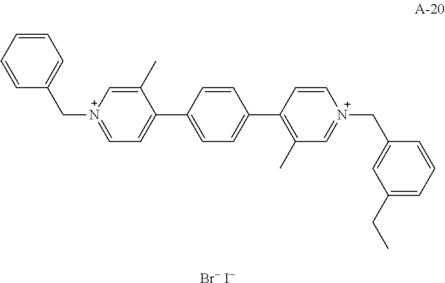


Claims (15)

Applications Claiming Priority (2)
| Application Number | Priority Date | Filing Date | Title |
|---|---|---|---|
| JP2017-028821 | 2017-02-20 | ||
| JP2017028821 | 2017-02-20 |
Publications (2)
| Publication Number | Publication Date |
|---|---|
| US20180237393A1 US20180237393A1 (en) | 2018-08-23 |
| US10364223B2 true US10364223B2 (en) | 2019-07-30 |
Family
ID=63166959
Family Applications (1)
| Application Number | Title | Priority Date | Filing Date |
|---|---|---|---|
| US15/895,056 Active 2038-02-18 US10364223B2 (en) | 2017-02-20 | 2018-02-13 | Organic compound, electrochromic element, optical filter, lens unit, image pickup apparatus, and window member |
Country Status (2)
| Country | Link |
|---|---|
| US (1) | US10364223B2 (en) |
| JP (1) | JP7030552B2 (en) |
Families Citing this family (2)
| Publication number | Priority date | Publication date | Assignee | Title |
|---|---|---|---|---|
| US10310350B2 (en) * | 2016-05-12 | 2019-06-04 | Canon Kabushiki Kaisha | Organic compound, electrochromic compound, and electrochromic element, optical filter, lens unit, imaging device, and window component having same |
| JP7446719B2 (en) * | 2018-06-28 | 2024-03-11 | キヤノン株式会社 | Organic compounds and electrochromic devices containing them, optical filters, lens units, imaging devices and windows |
Citations (12)
| Publication number | Priority date | Publication date | Assignee | Title |
|---|---|---|---|---|
| US7582363B2 (en) * | 2003-04-30 | 2009-09-01 | Showa Denko K.K. | Organic polymer light-emitting element material having gold complex structure and organic polymer light-emitting element |
| US8044224B2 (en) * | 2007-01-29 | 2011-10-25 | Sumitomo Chemical Company, Limited | Chiral iridium aqua complex and method for producing optically active hydroxy compound by using the same |
| US8507669B2 (en) * | 2008-04-11 | 2013-08-13 | Nippon Soda Co., Ltd. | Optically active dibenzazepine derivatives |
| JP2013193991A (en) | 2012-03-21 | 2013-09-30 | Ricoh Co Ltd | Electrochromic compound, electrochromic composition and display device |
| JP2015124228A (en) | 2013-12-25 | 2015-07-06 | 株式会社リコー | Electrochromic compound, electrochromic composition, and display element and dimmer element using the same |
| US9766527B2 (en) | 2015-07-02 | 2017-09-19 | Canon Kabushiki Kaisha | Electrochromic element, optical filter, lens unit, image pickup apparatus, and window member |
| US20170329195A1 (en) * | 2016-05-12 | 2017-11-16 | Canon Kabushiki Kaisha | Organic compound, electrochromic compound, and electrochromic element, optical filter, lens unit, imaging device, and window component having same |
| US9869919B2 (en) | 2015-07-02 | 2018-01-16 | Canon Kabushiki Kaisha | Electrochromic element, optical filter, lens unit, image pickup apparatus, and window member |
| US20180044581A1 (en) * | 2015-03-13 | 2018-02-15 | Toshiya Sagisaka | Electrochromic compound, electrochromic composition, electrochromic element, and electrochromic dimming element |
| US20180052375A1 (en) | 2015-07-10 | 2018-02-22 | Canon Kabushiki Kaisha | Electrochromic element, optical filter, lens unit, imaging apparatus, and window member |
| US9954187B2 (en) * | 2016-04-08 | 2018-04-24 | Idemitsu Kosan Co., Ltd. | Compound, organic electroluminescence device and electronic device |
| US20180259849A1 (en) * | 2015-12-17 | 2018-09-13 | Fujifilm Corporation | Near infrared absorbing composition, film, infrared cut filter, solid image pickup element, infrared absorber, and compound |
Family Cites Families (7)
| Publication number | Priority date | Publication date | Assignee | Title |
|---|---|---|---|---|
| JPS61148162A (en) * | 1984-12-20 | 1986-07-05 | Nippon Sheet Glass Co Ltd | Viologen derivative |
| JP4816069B2 (en) | 2005-12-26 | 2011-11-16 | ソニー株式会社 | Electrochromic device |
| JP5024592B2 (en) | 2006-05-09 | 2012-09-12 | ソニー株式会社 | Electrochromic device |
| JP2008089705A (en) | 2006-09-29 | 2008-04-17 | Sony Corp | Electrochromic device |
| CN104910892B (en) | 2012-11-14 | 2018-06-05 | 宁波祢若电子科技有限公司 | A kind of preparation method of electrochromic material |
| JP6598693B2 (en) | 2015-02-20 | 2019-10-30 | キヤノン株式会社 | Organic compound, electrochromic element having the same, optical filter, lens unit, imaging device, window material |
| EP3115433B1 (en) | 2015-07-08 | 2018-10-03 | Essilor International | Electrochromic compounds and optical articles containing them |
-
2018
- 2018-02-09 JP JP2018022090A patent/JP7030552B2/en active Active
- 2018-02-13 US US15/895,056 patent/US10364223B2/en active Active
Patent Citations (12)
| Publication number | Priority date | Publication date | Assignee | Title |
|---|---|---|---|---|
| US7582363B2 (en) * | 2003-04-30 | 2009-09-01 | Showa Denko K.K. | Organic polymer light-emitting element material having gold complex structure and organic polymer light-emitting element |
| US8044224B2 (en) * | 2007-01-29 | 2011-10-25 | Sumitomo Chemical Company, Limited | Chiral iridium aqua complex and method for producing optically active hydroxy compound by using the same |
| US8507669B2 (en) * | 2008-04-11 | 2013-08-13 | Nippon Soda Co., Ltd. | Optically active dibenzazepine derivatives |
| JP2013193991A (en) | 2012-03-21 | 2013-09-30 | Ricoh Co Ltd | Electrochromic compound, electrochromic composition and display device |
| JP2015124228A (en) | 2013-12-25 | 2015-07-06 | 株式会社リコー | Electrochromic compound, electrochromic composition, and display element and dimmer element using the same |
| US20180044581A1 (en) * | 2015-03-13 | 2018-02-15 | Toshiya Sagisaka | Electrochromic compound, electrochromic composition, electrochromic element, and electrochromic dimming element |
| US9766527B2 (en) | 2015-07-02 | 2017-09-19 | Canon Kabushiki Kaisha | Electrochromic element, optical filter, lens unit, image pickup apparatus, and window member |
| US9869919B2 (en) | 2015-07-02 | 2018-01-16 | Canon Kabushiki Kaisha | Electrochromic element, optical filter, lens unit, image pickup apparatus, and window member |
| US20180052375A1 (en) | 2015-07-10 | 2018-02-22 | Canon Kabushiki Kaisha | Electrochromic element, optical filter, lens unit, imaging apparatus, and window member |
| US20180259849A1 (en) * | 2015-12-17 | 2018-09-13 | Fujifilm Corporation | Near infrared absorbing composition, film, infrared cut filter, solid image pickup element, infrared absorber, and compound |
| US9954187B2 (en) * | 2016-04-08 | 2018-04-24 | Idemitsu Kosan Co., Ltd. | Compound, organic electroluminescence device and electronic device |
| US20170329195A1 (en) * | 2016-05-12 | 2017-11-16 | Canon Kabushiki Kaisha | Organic compound, electrochromic compound, and electrochromic element, optical filter, lens unit, imaging device, and window component having same |
Also Published As
| Publication number | Publication date |
|---|---|
| JP7030552B2 (en) | 2022-03-07 |
| US20180237393A1 (en) | 2018-08-23 |
| JP2018135327A (en) | 2018-08-30 |
Similar Documents
| Publication | Publication Date | Title |
|---|---|---|
| JP6900202B2 (en) | Organic compounds, electrochromic elements, electrochromic devices, optical filters, imaging devices, lens units and window materials | |
| US9701671B2 (en) | Organic compound, electrochromic element containing the same, optical filter, lens unit, imaging device, and window component | |
| US11319483B2 (en) | Organic compound, electrochromic element containing the same, optical filter, lens unit, imaging device, and window material | |
| US10310350B2 (en) | Organic compound, electrochromic compound, and electrochromic element, optical filter, lens unit, imaging device, and window component having same | |
| WO2017154681A1 (en) | Organic compound, electrochromic element, electrochromic device, optical filter, imaging device, lens unit, and window material | |
| JP6598693B2 (en) | Organic compound, electrochromic element having the same, optical filter, lens unit, imaging device, window material | |
| JP2018024624A (en) | Organic compound, and electrochromic element, optical film, lens unit, and imaging device having the same | |
| US10907091B2 (en) | Organic compound and electrochromic element | |
| US9310660B2 (en) | Organic compound and electrochromic element including the same | |
| US10364223B2 (en) | Organic compound, electrochromic element, optical filter, lens unit, image pickup apparatus, and window member | |
| JP6991731B2 (en) | Organic compounds, electrochromic compounds, and electrochromic elements having them, optical filters, lens units, image pickup devices, window materials | |
| JP2017197477A (en) | Organic compound, and electrochromic element, optical filter, lens unit, imaging device and window material having the same | |
| US11940704B2 (en) | Organic compound, and electrochromic element, optical filter, image pickup apparatus, window, and electrochromic mirror containing the same | |
| US20210191217A1 (en) | Organic compound and electrochromic element | |
| US11104844B2 (en) | Organic compound, electrochromic device, optical filter, image pickup apparatus, window, and electrochromic mirror | |
| US20230416222A1 (en) | Organic compound and electrochromic element | |
| JP7166939B2 (en) | Organic compounds and electrochromic devices | |
| EP3839007A1 (en) | Organic compound and electrochromic element | |
| JP6921590B2 (en) | Organic compounds, electrochromic elements containing them, optical filters, lens units, imaging devices, window materials | |
| JP2021109862A (en) | Organic compound and electrochromic element | |
| JP2022070461A (en) | Organic compound, electrochromic element, optical filter, lens unit, imaging device, and window | |
| JP2021011441A (en) | Organic compound, and electrochromic element, optical film, lens unit, imaging device and window material containing the same |
Legal Events
| Date | Code | Title | Description |
|---|---|---|---|
| FEPP | Fee payment procedure |
Free format text: ENTITY STATUS SET TO UNDISCOUNTED (ORIGINAL EVENT CODE: BIG.); ENTITY STATUS OF PATENT OWNER: LARGE ENTITY |
|
| STPP | Information on status: patent application and granting procedure in general |
Free format text: DOCKETED NEW CASE - READY FOR EXAMINATION |
|
| AS | Assignment |
Owner name: CANON KABUSHIKI KAISHA, JAPAN Free format text: ASSIGNMENT OF ASSIGNORS INTEREST;ASSIGNORS:TAMURA, TETSUYA;IGAWA, SATOSHI;SIGNING DATES FROM 20180301 TO 20180313;REEL/FRAME:045728/0461 |
|
| STPP | Information on status: patent application and granting procedure in general |
Free format text: NOTICE OF ALLOWANCE MAILED -- APPLICATION RECEIVED IN OFFICE OF PUBLICATIONS |
|
| STPP | Information on status: patent application and granting procedure in general |
Free format text: PUBLICATIONS -- ISSUE FEE PAYMENT VERIFIED |
|
| STCF | Information on status: patent grant |
Free format text: PATENTED CASE |
|
| MAFP | Maintenance fee payment |
Free format text: PAYMENT OF MAINTENANCE FEE, 4TH YEAR, LARGE ENTITY (ORIGINAL EVENT CODE: M1551); ENTITY STATUS OF PATENT OWNER: LARGE ENTITY Year of fee payment: 4 |