JP7024042B2 - Pachinko machine - Google Patents
Pachinko machine Download PDFInfo
- Publication number
- JP7024042B2 JP7024042B2 JP2020186330A JP2020186330A JP7024042B2 JP 7024042 B2 JP7024042 B2 JP 7024042B2 JP 2020186330 A JP2020186330 A JP 2020186330A JP 2020186330 A JP2020186330 A JP 2020186330A JP 7024042 B2 JP7024042 B2 JP 7024042B2
- Authority
- JP
- Japan
- Prior art keywords
- display
- game
- special
- state
- variable display
- Prior art date
- Legal status (The legal status is an assumption and is not a legal conclusion. Google has not performed a legal analysis and makes no representation as to the accuracy of the status listed.)
- Active
Links
Images


Description
この発明は、特別識別情報として第1特別識別情報および前記第1特別識別情報よりも遊技者にとって有利な第2特別識別情報の変動表示を実行可能であり、遊技者にとって有利な有利状態に制御可能な遊技機に関する。 INDUSTRIAL APPLICABILITY According to the present invention, it is possible to execute variable display of the first special identification information and the second special identification information which is more advantageous to the player than the first special identification information as the special identification information, and the control is performed in an advantageous state which is advantageous to the player. Regarding possible gaming machines.
従来、複数の設定値のうちのいずれかに設定可能であり、設定された設定値にもとづいて遊技者にとって有利な有利状態の制御を実行可能なパチンコ遊技機があった。このようなパチンコ遊技機において、設定値を確認するための設定確認処理では、実行中のメイン処理が全て終了したときにしか次の処理へ移行できなかった(例えば、特許文献1参照)。 Conventionally, there has been a pachinko gaming machine that can be set to any of a plurality of set values and can control an advantageous state that is advantageous to the player based on the set set value. In such a pachinko gaming machine, in the setting confirmation process for confirming the set value, the process can be shifted to the next process only when all the main processes being executed are completed (see, for example, Patent Document 1).
また、変動表示に対応する対応表示(いわゆるアクティブ表示)を複数回の変動に亘って引継いでいくことが可能な遊技機があった(たとえば、特許文献2および特許文献3参照)。
In addition, there is a gaming machine capable of taking over the corresponding display (so-called active display) corresponding to the variable display over a plurality of fluctuations (see, for example,
しかしながら、特許文献1にあっては、設定確認をすぐに行いたい状況のときに、実行中の全ての処理が終わるまで待たねばならず、好適に設定確認作業を実行することできないという問題がある。 However, in
本発明は、このような問題点に着目してなされたもので、好適に設定確認作業を実行することができる遊技機を提供することを目的とする。 The present invention has been made by paying attention to such a problem, and an object of the present invention is to provide a gaming machine capable of suitably performing a setting confirmation work.
(A) 可変表示を実行し、遊技者にとって有利な有利状態に制御可能な遊技機であって、
前記有利状態に制御される確率に関する設定値を設定可能な設定手段と、
前記設定手段により設定された設定値を確認可能な設定確認状態に制御可能な設定確認制御手段と、
遊技に関する処理を実行可能な割込処理を実行する割込処理実行手段と、
前記有利状態が終了したことに応じて報知演出を実行可能な報知演出実行手段と、
前記報知演出が実行される報知期間を計時する報知計時手段と、
特別識別情報の可変表示を行い、可変表示結果を表示可能な特別可変表示手段と、
特別識別情報の可変表示を行う特別可変表示期間を計時する特別可変表示計時手段と、
可変表示が停止した後から次の可変表示が開始されるまでの可変表示停止期間を計時する停止期間計時手段と、を備え、
前記設定確認制御手段は、遊技機への電力供給が開始したときであって前記割込処理が許可される前に前記設定確認状態に制御可能であり、
前記設定確認状態が終了したときに前記割込処理が許可され、該割込処理が許可された後、遊技機への電力供給が停止されるまで前記設定確認状態に制御されず、
前記報知期間が計時されているときに遊技機への電力供給が停止され、その後に遊技機への電力供給が再開して前記設定確認状態に制御された場合に、該設定確認状態が終了するまで前記報知期間の計時が中断され、該設定確認状態が終了したときに前記報知期間の計時が再開され、
前記特別可変表示期間が計時されているときに遊技機への電力供給が停止され、その後に遊技機への電力供給が再開して前記設定確認状態に制御された場合に、該設定確認状態が終了するまで前記特別可変表示期間の計時が中断され、該設定確認状態が終了したときに前記特別可変表示期間の計時が再開され、
前記可変表示停止期間が計時されているときに遊技機への電力供給が停止され、その後に遊技機への電力供給が再開して前記設定確認状態に制御された場合に、該設定確認状態が終了するまで前記可変表示停止期間の計時が中断され、該設定確認状態が終了したときに前記可変表示停止期間の計時が再開される、
ことを特徴とする。この特徴によれば好適に設定確認作業を行うことが出来る。
(1) 特別識別情報(たとえば、特別図柄)として第1特別識別情報(たとえば、第1特別図柄)および前記第1特別識別情報よりも遊技者にとって有利な第2特別識別情報(たとえば、第2特別図柄)の変動表示を実行可能であり、遊技者にとって有利な有利状態(たとえば、大当り遊技状態)に制御可能な遊技機(たとえば、パチンコ遊技機1)であって、
変動表示に対応する対応表示(たとえば、アクティブ表示)を表示可能な対応表示手段(たとえば、演出制御用CPU120)を備え、
前記対応表示手段は、
前記有利状態に制御される期待度に応じて、通常態様および前記通常態様と異なる複数種類の特別態様(たとえば、図8-8および図8-9(E)~(H)で示す緑色,赤色の表示態様。他の色,形状,模様の表示態様であってもよい。)のいずれかの表示態様の対応表示を表示可能であり、
少なくとも前記第1特別識別情報および前記第2特別識別情報の変動表示を含む複数の変動表示に亘って、前記特別態様の対応表示を引継いで表示することが可能であり(たとえば、図8-8のパターンγ1~γ3のアクティブ表示変化演出)、
前記第1特別識別情報の変動表示から前記第2特別識別情報の変動表示に亘って対応表示の表示態様を引継ぐ割合の方が、前記第2特別識別情報の変動表示から前記第1特別識別情報の変動表示に亘って対応表示の表示態様を引継ぐ割合よりも高い(たとえば、図8-8で示すように、はずれ時および大当り時に、第1特別図柄の変動表示から第2特別図柄の変動表示に亘ってアクティブ表示の表示態様を特別態様の緑から緑,緑から赤,赤から赤に引継ぐ割合の方が、第2特別図柄の変動表示から第1特別図柄の変動表示に亘ってアクティブ表示の表示態様を特別態様の緑から緑,緑から赤,赤から赤に引継ぐ割合よりも高い)。
(A) A gaming machine capable of executing variable display and controlling to an advantageous state advantageous to the player .
A setting means capable of setting a setting value regarding the probability of being controlled to the advantageous state, and a setting means.
A setting confirmation control means capable of controlling a setting confirmation state in which the setting value set by the setting means can be confirmed, and a setting confirmation control means.
An interrupt process execution means that executes an interrupt process that can execute a game-related process,
A notification effect execution means capable of executing a notification effect according to the end of the advantageous state, and a notification effect execution means.
A notification timekeeping means for measuring the notification period in which the notification effect is executed, and
A special variable display means that can display the variable display result by variable display of the special identification information,
Special variable display timekeeping means for measuring the special variable display period for variable display of special identification information,
It is equipped with a stop period timing means for measuring the variable display stop period from the time when the variable display is stopped until the next variable display is started.
The setting confirmation control means can control the setting confirmation state when the power supply to the gaming machine is started and before the interruption process is permitted.
When the setting confirmation state is completed, the interrupt processing is permitted, and after the interruption processing is permitted, the setting confirmation state is not controlled until the power supply to the gaming machine is stopped.
When the power supply to the gaming machine is stopped when the notification period is timed, and then the power supply to the gaming machine is restarted and controlled to the setting confirmation state, the setting confirmation state ends. The timing of the notification period is interrupted until, and when the setting confirmation state is completed, the timing of the notification period is restarted.
When the power supply to the gaming machine is stopped when the special variable display period is timed, and then the power supply to the gaming machine is restarted and controlled to the setting confirmation state, the setting confirmation state is changed. The time counting of the special variable display period is interrupted until the end, and when the setting confirmation state ends, the time counting of the special variable display period is restarted.
When the power supply to the gaming machine is stopped when the variable display stop period is timed, and then the power supply to the gaming machine is restarted and controlled to the setting confirmation state, the setting confirmation state is changed. The time counting of the variable display stop period is interrupted until the end, and when the setting confirmation state ends, the time measurement of the variable display stop period is restarted.
It is characterized by that. According to this feature, the setting confirmation work can be preferably performed.
(1) The first special identification information (for example, the first special symbol) as the special identification information (for example, the special symbol) and the second special identification information (for example, the second) that is more advantageous to the player than the first special identification information. It is a gaming machine (for example, pachinko gaming machine 1) that can execute variable display of a special symbol) and can be controlled to an advantageous state (for example, a big hit gaming state) that is advantageous to the player.
A corresponding display means (for example, a
The corresponding display means is
Depending on the degree of expectation controlled by the advantageous state, a normal mode and a plurality of special modes different from the normal mode (for example, green and red shown in FIGS. 8-8 and 8-9 (E) to (H)). Display mode. It may be a display mode of another color, shape, or pattern.) It is possible to display the corresponding display of any of the display modes.
It is possible to take over and display the corresponding display of the special aspect over at least a plurality of variable displays including the variable display of the first special identification information and the second special identification information (for example, FIG. 8-8). Active display change effect of patterns γ1 to γ3),
The ratio of inheriting the display mode of the corresponding display from the variable display of the first special identification information to the variable display of the second special identification information is the ratio of the variable display of the second special identification information to the first special identification information. It is higher than the ratio of inheriting the display mode of the corresponding display over the variation display of (for example, as shown in FIG. 8-8, the variation display of the first special symbol to the variation display of the second special symbol at the time of a miss and a big hit. The ratio of inheriting the display mode of the active display from green to green, green to red, and red to red in the special mode is the active display from the variable display of the second special symbol to the variable display of the first special symbol. Is higher than the ratio of inheriting the display mode from green to green, green to red, and red to red in the special mode).
このような構成によれば、遊技者にとって不利な第1特別識別情報の変動表示に対応する対応表示が期待度の高い表示態様で表示されたとしても、対応表示が期待度の高い表示態様で引継がれることに遊技者は期待できる。その結果、遊技の興趣を向上させることができる。 According to such a configuration, even if the corresponding display corresponding to the variable display of the first special identification information, which is disadvantageous to the player, is displayed in the display mode with high expectation, the corresponding display is displayed in the display mode with high expectation. Players can expect to be taken over. As a result, the interest of the game can be improved.
(2) 上記(1)の遊技機において、
前記遊技機は、遊技媒体(たとえば、遊技球)を用いて所定の遊技(たとえば、パチンコ遊技)を行うことが可能であり、
遊技媒体が進入可能な遊技領域(たとえば、遊技領域)と、
前記遊技領域に設けられ、遊技媒体が通過可能な第1始動領域(たとえば、第1始動入賞口63)および第2始動領域(たとえば、第2始動入賞口64)と、
前記遊技領域に設けられ、前記第1始動領域と前記第2始動領域とに遊技媒体を振り分けるための振分装置(たとえば、振分け入賞装置60)とをさらに備え、
遊技媒体が前記第1始動領域を通過した後に第1開始条件(たとえば、他の変動表示が実行されていないとの条件、大当り遊技状態中でないとの条件)が成立したことに基づいて、前記第1特別識別情報の変動表示を開始し、
遊技媒体が前記第2始動領域を通過した後に第2開始条件(たとえば、他の変動表示が実行されていないとの条件、大当り遊技状態中でないとの条件)が成立したことに基づいて、前記第2特別識別情報の変動表示を開始し、
前記振分装置は、当該振分装置に流入した遊技媒体を、前記第1始動領域に振分け易い第1状態(たとえば、振分け部材67が左回りに回動した状態)と、前記第2始動領域に振分け易い第2状態(たとえば、振分け部材67が右回りに回動した状態)とに交互に変化し、
前記第1始動領域を遊技媒体が通過したが前記第1開始条件が成立していない前記第1特別識別情報の変動表示に関する情報を第1保留記憶情報として記憶する第1保留記憶手段(たとえば、RAM55の保留特定領域のうち第1特別図柄に対応する保留記憶が記憶されている領域)と、
前記第2始動領域を遊技媒体が通過したが前記第2開始条件が成立していない前記第2特別識別情報の変動表示に関する情報を第2保留記憶情報として記憶する第2保留記憶手段(たとえば、RAM55の保留特定領域のうち第2特別図柄に対応する保留記憶が記憶されている領域)とをさらに備え、
前記第1開始条件および前記第2開始条件は、遊技媒体が前記第1始動領域および前記第2始動領域を通過した順に成立する(たとえば、図8-5参照)。
(2) In the gaming machine of (1) above
The game machine can play a predetermined game (for example, a pachinko game) using a game medium (for example, a game ball).
A game area (for example, a game area) in which a game medium can enter, and
A first starting area (for example, a first starting winning opening 63) and a second starting area (for example, a second starting winning opening 64) provided in the gaming area and through which a game medium can pass are
A distribution device (for example, a distribution winning device 60) provided in the game area for distributing the game medium to the first start area and the second start area is further provided.
The above is based on the fact that the first start condition (for example, the condition that other variable display is not executed, the condition that the jackpot game state is not in progress) is satisfied after the game medium has passed through the first start region. The variable display of the first special identification information is started,
The above is based on the fact that the second start condition (for example, the condition that other variable display is not executed, the condition that the jackpot game state is not in progress) is satisfied after the game medium has passed through the second start region. Started variable display of the second special identification information,
The distribution device has a first state (for example, a state in which the
A first reserved storage means (for example,) that stores information related to variable display of the first special identification information as first reserved storage information, although the gaming medium has passed through the first starting region but the first starting condition is not satisfied. Of the reserved specific areas of the
A second reserved storage means (for example,) that stores information regarding the variable display of the second special identification information as the second reserved storage information, although the gaming medium has passed through the second starting region but the second starting condition is not satisfied. Of the reserved specific areas of the
The first start condition and the second start condition are satisfied in the order in which the game medium passes through the first start region and the second start region (see, for example, FIG. 8-5).
このような構成によれば、遊技者にとって不利な第1特別識別情報の変動表示に対応する対応表示が期待度の高い表示態様で表示されたとしても、対応表示が期待度の高い表示態様で引継がれることに遊技者は期待できる。その結果、遊技の興趣を向上させることができる。 According to such a configuration, even if the corresponding display corresponding to the variable display of the first special identification information, which is disadvantageous to the player, is displayed in the display mode with high expectation, the corresponding display is displayed in the display mode with high expectation. Players can expect to be taken over. As a result, the interest of the game can be improved.
(3) 上記(1)または(2)の遊技機において、
前記第2特別識別情報の変動表示に対応する前記有利状態の方が、前記第1特別識別情報の変動表示に対応する前記有利状態よりも、前記有利状態の後に、前記有利状態に制御
される確率が通常状態に制御されている場合よりも向上した、確率変動状態に制御される割合が高い(たとえば、第1特別図柄よりも第2特別図柄の方が、確変割合を高くするように構成する)。
(3) In the gaming machine of (1) or (2) above
The advantageous state corresponding to the variable display of the second special identification information is controlled to the advantageous state after the advantageous state than the advantageous state corresponding to the variable display of the first special identification information. The rate of control to the probability fluctuation state is higher than that of the case where the probability is controlled to the normal state (for example, the second special symbol is configured to have a higher probability variation rate than the first special symbol). do).
このような構成によれば、遊技者にとって不利な第1特別識別情報の変動表示に対応する対応表示が期待度の高い表示態様で表示されたとしても、対応表示が期待度の高い表示態様で引継がれることに遊技者は期待できる。その結果、遊技の興趣を向上させることができる。 According to such a configuration, even if the corresponding display corresponding to the variable display of the first special identification information, which is disadvantageous to the player, is displayed in the display mode with high expectation, the corresponding display is displayed in the display mode with high expectation. Players can expect to be taken over. As a result, the interest of the game can be improved.
(4) 上記(1)から(3)の遊技機において、
前記第2特別識別情報の変動表示に対応する前記有利状態の方が、前記第1特別識別情報の変動表示に対応する前記有利状態よりも、前記有利状態において遊技者に付与される遊技媒体の数の期待値が高い(たとえば、第1特別図柄よりも第2特別図柄の方が、大当り遊技状態における賞球数を多くするため、大当りのラウンド数の平均値が高くなるように構成する)。
(4) In the gaming machines (1) to (3) above,
The advantageous state corresponding to the variable display of the second special identification information is a gaming medium given to the player in the advantageous state than the advantageous state corresponding to the variable display of the first special identification information. The expected value of the number is high (for example, the second special symbol is configured so that the average value of the number of rounds of the jackpot is higher in order to increase the number of prize balls in the jackpot game state than the first special symbol). ..
このような構成によれば、遊技者にとって不利な第1特別識別情報の変動表示に対応する対応表示が期待度の高い表示態様で表示されたとしても、対応表示が期待度の高い表示態様で引継がれることに遊技者は期待できる。その結果、遊技の興趣を向上させることができる。 According to such a configuration, even if the corresponding display corresponding to the variable display of the first special identification information, which is disadvantageous to the player, is displayed in the display mode with high expectation, the corresponding display is displayed in the display mode with high expectation. Players can expect to be taken over. As a result, the interest of the game can be improved.
(5) 上記(1)から(4)の遊技機において、
前記第2特別識別情報の変動表示から前記第1特別識別情報の変動表示に亘って対応表示の表示態様を引継ぐ場合の方が、前記第1特別識別情報の変動表示から前記第2特別識別情報の変動表示に亘って対応表示の表示態様を引継ぐ場合よりも、遊技者にとって有利な状態となる期待度が高い(たとえば、第2特別図柄から第1特別図柄の変動表示に亘ってアクティブ表示の表示態様として特別態様を引継ぐ場合の方が、第1特別図柄から第2特別図柄の変動表示に亘ってアクティブ表示の表示態様として特別態様を引継ぐ場合よりも、大当り遊技状態となる期待度が高くなるように構成してもよい)。
(5) In the gaming machines (1) to (4) above,
In the case where the display mode of the corresponding display is inherited from the variable display of the second special identification information to the variable display of the first special identification information, the second special identification information is transferred from the variable display of the first special identification information. There is a higher expectation that the player will be in an advantageous state than in the case of inheriting the display mode of the corresponding display over the variable display of (for example, the active display from the second special symbol to the first special symbol). The case where the special mode is inherited as the display mode is more likely to be in the big hit game state than the case where the special mode is inherited as the display mode of the active display from the first special symbol to the second special symbol variable display. It may be configured to be).
このような構成によれば、遊技者にとって不利な第1特別識別情報の変動表示に対応表示の表示態様が引継がれても、遊技者にとって有利な状態となる期待度が高いため、遊技の興趣の低下を防止できる。 According to such a configuration, even if the display mode of the display corresponding to the variable display of the first special identification information, which is disadvantageous to the player, is taken over, it is highly expected that the display mode will be advantageous to the player. Can be prevented from decreasing.
(6) 上記(1)から(5)の遊技機において、
前記対応表示手段は、前記第2特別識別情報の変動表示に対応する前記特別態様の対応表示を、前記第1特別識別情報の変動表示に対応する対応表示に引継いだ後、さらに、前記第2特別識別情報の変動表示に対応する対応表示に引継ぐことが可能である(たとえば、本実施の形態においては図8-8のパターンγ1~γ3で示したように2段階でアクティブ表示の特別態様を引継ぐようにした。しかし、これに限定されず、第2特別図柄の変動表示を対象としたアクティブ表示変化演出の場合は、特に、3段階で引継ぐようにしてもよい。)。
(6) In the gaming machines (1) to (5) above,
The corresponding display means takes over the corresponding display of the special aspect corresponding to the variable display of the second special identification information to the corresponding display corresponding to the variable display of the first special identification information, and then further, the second. It is possible to take over to the corresponding display corresponding to the variable display of the special identification information (for example, in the present embodiment, as shown by the patterns γ1 to γ3 in FIGS. 8-8, the special mode of the active display is provided in two stages. However, it is not limited to this, and in the case of the active display change effect targeting the variable display of the second special symbol, it may be taken over in three stages in particular).
このような構成によれば、対応表示の表示態様が、一旦、遊技者にとって不利な第1特別識別情報の変動表示の対応表示の表示態様に引継がれたとしても、その後に、再度、遊技者にとって有利な第2特別識別情報の変動表示の対応表示の表示態様に引継がれることがあるため、遊技の興趣の低下を防止できる。 According to such a configuration, even if the display mode of the corresponding display is once taken over by the display mode of the corresponding display of the variable display of the first special identification information which is disadvantageous to the player, after that, the player again. Since the display mode of the corresponding display of the variable display of the second special identification information, which is advantageous for the user, may be taken over, it is possible to prevent a decrease in the interest of the game.
(7) 上記(1)から(6)の遊技機において、
前記対応表示手段は、対応表示を引継ぐときに、前の変動表示の終了時に当該変動表示
に対応する対応表示を、一旦、消去し、次の変動表示の開始時に、表示態様を引継いだ当該変動表示に対応する対応表示を表示する(たとえば、図8-9(F)から図8-9(G)に移行するときに、緑色の表示態様のアクティブ表示を一旦消去した後に、赤色の表示態様のアクティブ表示を表示する)。
(7) In the gaming machines (1) to (6) above,
When the corresponding display means takes over the corresponding display, the corresponding display corresponding to the variable display is temporarily deleted at the end of the previous variable display, and the display mode is taken over at the start of the next variable display. Display the corresponding display corresponding to the display (for example, when shifting from FIG. 8-9 (F) to FIG. 8-9 (G), the active display of the green display mode is once erased, and then the red display mode is displayed. Show the active display of).
このような構成によれば、対応表示の表示態様が、一旦、消えたように見せかけて、再度、表示されるので、遊技の興趣を向上させることができる。 According to such a configuration, the display mode of the corresponding display appears to have disappeared once and is displayed again, so that the interest of the game can be improved.
(8) 上記(1)から(7)の遊技機において、
前記対応表示手段によって対応表示の表示態様が引継がれることを示唆する引継示唆演出(たとえば、保留表示変化演出、保留表示に追加表示を表示する演出)を実行可能な引継示唆演出実行手段(たとえば、演出制御用CPU120。図8-9で示したように、保留表示変化演出で白色で点滅する特殊態様に変化した保留表示が、特別態様のアクティブ表示に変化するようにし、その特別態様が次の変動表示に対応するアクティブ表示に引継がれるようにする。)をさらに備える。
(8) In the gaming machines (1) to (7) above,
A takeover suggestion effect execution means (for example, a hold display change effect, an effect of displaying an additional display on the hold display) that suggests that the display mode of the corresponding display is inherited by the corresponding display means. The
このような構成によれば、引継示唆演出によって遊技者の期待感を高めることができる。その結果、遊技の興趣を向上させることができる。 According to such a configuration, the player's expectation can be raised by the takeover suggestion effect. As a result, the interest of the game can be improved.
(基本説明)
まず、パチンコ遊技機1の基本的な構成及び制御(一般的なパチンコ遊技機の構成及び制御でもある。)について説明する。
(Basic explanation)
First, the basic configuration and control of the pachinko gaming machine 1 (also the configuration and control of a general pachinko gaming machine) will be described.
(パチンコ遊技機1の構成等)
図1は、パチンコ遊技機1の正面図であり、主要部材の配置レイアウトを示す。パチンコ遊技機(遊技機)1は、大別して、遊技盤面を構成する遊技盤(ゲージ盤)2と、遊技盤2を支持固定する遊技機用枠(台枠)3とから構成されている。遊技盤2には、遊技領域が形成され、この遊技領域には、遊技媒体としての遊技球が、所定の打球発射装置から発射されて打ち込まれる。
(Configuration of
FIG. 1 is a front view of the
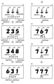
遊技盤2の所定位置(図1に示す例では、遊技領域の右側方)には、複数種類の特別識別情報としての特別図柄(特図ともいう)の可変表示(特図ゲームともいう)を行う第1特別図柄表示装置4A及び第2特別図柄表示装置4Bが設けられている。これらは、それぞれ、7セグメントのLEDなどからなる。特別図柄は、「0」~「9」を示す数字や「
-」などの点灯パターンなどにより表される。特別図柄には、LEDを全て消灯したパターンが含まれてもよい。
A variable display (also referred to as a special figure game) of a special symbol (also referred to as a special figure) as a plurality of types of special identification information is displayed at a predetermined position of the game board 2 (in the example shown in FIG. 1, on the right side of the game area). The first special
It is represented by a lighting pattern such as "-". The special symbol may include a pattern in which all the LEDs are turned off.
なお、特別図柄の「可変表示(変動表示)」とは、例えば、複数種類の特別図柄を変動可能に表示することである(後述の他の図柄についても同じ)。変動としては、複数の図柄の更新表示、複数の図柄のスクロール表示、1以上の図柄の変形、1以上の図柄の拡大/縮小などがある。特別図柄や後述の普通図柄の変動では、複数種類の特別図柄又は普通図柄が更新表示される。後述の飾り図柄の変動では、複数種類の飾り図柄がスクロール表示又は更新表示されたり、1以上の飾り図柄が変形や拡大/縮小されたりする。なお、変動には、ある図柄を点滅表示する態様も含まれる。可変表示の最後には、表示結果として所定の特別図柄が停止表示(導出又は導出表示などともいう)される(後述の他の図柄の可変表示についても同じ)。なお、可変表示を変動表示、変動と表現する場合がある。 The "variable display (variable display)" of the special symbol is, for example, to display a plurality of types of special symbols in a variable manner (the same applies to other symbols described later). Variations include update display of a plurality of symbols, scroll display of a plurality of symbols, deformation of one or more symbols, enlargement / reduction of one or more symbols, and the like. In the variation of the special symbol or the ordinary symbol described later, a plurality of types of special symbols or ordinary symbols are updated and displayed. In the variation of the decorative symbol described later, a plurality of types of decorative symbols are scrolled or updated, and one or more decorative symbols are deformed or enlarged / reduced. It should be noted that the fluctuation includes a mode in which a certain symbol is blinking and displayed. At the end of the variable display, a predetermined special symbol is stopped and displayed (also referred to as derivation or derivation display) as a display result (the same applies to the variable display of other symbols described later). The variable display may be expressed as variable display or variable.
なお、第1特別図柄表示装置4Aにおいて可変表示される特別図柄を「第1特図」ともいい、第2特別図柄表示装置4Bにおいて可変表示される特別図柄を「第2特図」ともいう。また、第1特図を用いた特図ゲームを「第1特図ゲーム」といい、第2特図を用いた特図ゲームを「第2特図ゲーム」ともいう。なお、特別図柄の可変表示を行う特別図柄表示装置は1種類であってもよい。
The special symbol variably displayed on the first special
遊技盤2における遊技領域の中央付近には画像表示装置5が設けられている。画像表示装置5は、例えばLCD(液晶表示装置)や有機EL(Electro Luminescence)等から構成され、各種の演出画像を表示する。画像表示装置5は、プロジェクタ及びスクリーンから構成されていてもよい。画像表示装置5には、各種の演出画像が表示される。
An
例えば、画像表示装置5の画面上では、第1特図ゲームや第2特図ゲームと同期して、特別図柄とは異なる複数種類の装飾識別情報としての飾り図柄(数字などを示す図柄など、演出図柄)の可変表示が行われる。ここでは、第1特図ゲーム又は第2特図ゲームに同期して、「左」、「中」、「右」の各飾り図柄表示エリア5L、5C、5Rにおいて飾り図柄が可変表示(例えば上下方向のスクロール表示や更新表示)される。なお、同期して実行される特図ゲーム及び飾り図柄の可変表示を総称して単に可変表示ともいう。
For example, on the screen of the
画像表示装置5の画面上には、実行が保留されている可変表示に対応する保留表示や、実行中の可変表示に対応するアクティブ表示を表示するための表示エリアが設けられていてもよい。保留表示及びアクティブ表示を総称して可変表示に対応する可変表示対応表示ともいう。
On the screen of the
保留されている可変表示の数は保留記憶数ともいう。第1特図ゲームに対応する保留記憶数を第1保留記憶数、第2特図ゲームに対応する保留記憶数を第2保留記憶数ともいう。また、第1保留記憶数と第2保留記憶数との合計を合計保留記憶数ともいう。 The number of variable displays on hold is also called the number of hold storages. The number of reserved storage corresponding to the first special figure game is also referred to as the first reserved storage number, and the number of reserved storage corresponding to the second special figure game is also referred to as the second reserved storage number. Further, the total of the first reserved storage number and the second reserved storage number is also referred to as a total reserved storage number.
また、遊技盤2の所定位置には、複数のLEDを含んで構成された第1保留表示器25Aと第2保留表示器25Bとが設けられ、第1保留表示器25Aは、LEDの点灯個数によって、第1保留記憶数を表示し、第2保留表示器25Bは、LEDの点灯個数によって、第2保留記憶数を表示する。
Further, at a predetermined position of the
画像表示装置5の下方には、入賞球装置6Aと、可変入賞球装置6Bとが設けられている。
Below the
入賞球装置6Aは、例えば所定の玉受部材によって常に遊技球が進入可能な一定の開放状態に保たれる第1始動入賞口を形成する。第1始動入賞口に遊技球が進入したときには
、所定個(例えば3個)の賞球が払い出されるとともに、第1特図ゲームが開始され得る。
The winning
可変入賞球装置6B(普通電動役物)は、ソレノイド81(図2参照)によって閉鎖状態と開放状態とに変化する第2始動入賞口を形成する。可変入賞球装置6Bは、例えば、一対の可動翼片を有する電動チューリップ型役物を備え、ソレノイド81がオフ状態であるときに可動翼片が垂直位置となることにより、当該可動翼片の先端が入賞球装置6Aに近接し、第2始動入賞口に遊技球が進入しない閉鎖状態になる(第2始動入賞口が閉鎖状態になるともいう。)。その一方で、可変入賞球装置6Bは、ソレノイド81がオン状態であるときに可動翼片が傾動位置となることにより、第2始動入賞口に遊技球が進入できる開放状態になる(第2始動入賞口が開放状態になるともいう。)。第2始動入賞口に遊技球が進入したときには、所定個(例えば3個)の賞球が払い出されるとともに、第2特図ゲームが開始され得る。なお、可変入賞球装置6Bは、閉鎖状態と開放状態とに変化するものであればよく、電動チューリップ型役物を備えるものに限定されない。
The variable winning
遊技盤2の所定位置(図1に示す例では、遊技領域の左右下方4箇所)には、所定の玉受部材によって常に一定の開放状態に保たれる一般入賞口10が設けられる。この場合には、一般入賞口10のいずれかに進入したときには、所定個数(例えば10個)の遊技球が賞球として払い出される。
At a predetermined position of the game board 2 (in the example shown in FIG. 1, four locations on the lower left and right sides of the game area), a general winning
入賞球装置6Aと可変入賞球装置6Bの下方には、大入賞口を有する特別可変入賞球装置7が設けられている。特別可変入賞球装置7は、ソレノイド82(図2参照)によって開閉駆動される大入賞口扉を備え、その大入賞口扉によって開放状態と閉鎖状態とに変化する特定領域としての大入賞口を形成する。
Below the winning
一例として、特別可変入賞球装置7では、大入賞口扉用(特別電動役物用)のソレノイド82がオフ状態であるときに大入賞口扉が大入賞口を閉鎖状態として、遊技球が大入賞口に進入(通過)できなくなる。その一方で、特別可変入賞球装置7では、大入賞口扉用のソレノイド82がオン状態であるときに大入賞口扉が大入賞口を開放状態として、遊技球が大入賞口に進入しやすくなる。
As an example, in the special variable winning
大入賞口に遊技球が進入したときには、所定個数(例えば14個)の遊技球が賞球として払い出される。大入賞口に遊技球が進入したときには、例えば第1始動入賞口や第2始動入賞口及び一般入賞口10に遊技球が進入したときよりも多くの賞球が払い出される。
When a game ball enters the large prize opening, a predetermined number (for example, 14) of game balls are paid out as prize balls. When a game ball enters the large winning opening, more prize balls are paid out than when the game ball enters, for example, the first starting winning opening, the second starting winning opening, and the general winning
一般入賞口10を含む各入賞口に遊技球が進入することを「入賞」ともいう。特に、始動口(第1始動入賞口、第2始動入賞口始動口)への入賞を始動入賞ともいう。
The entry of a game ball into each winning opening including the general winning
遊技盤2の所定位置(図1に示す例では、遊技領域の左側方)には、普通図柄表示器20が設けられている。一例として、普通図柄表示器20は、7セグメントのLEDなどからなり、特別図柄とは異なる複数種類の普通識別情報としての普通図柄の可変表示を行う。普通図柄は、「0」~「9」を示す数字や「-」などの点灯パターンなどにより表される。普通図柄には、LEDを全て消灯したパターンが含まれてもよい。このような普通図柄の可変表示は、普図ゲームともいう。
A
画像表示装置5の左方には、遊技球が通過可能な通過ゲート41(「ゲート」ともいう)が設けられている。遊技球が通過ゲート41を通過したことに基づき、普図ゲームが実行される。
A passing gate 41 (also referred to as a “gate”) through which a game ball can pass is provided on the left side of the
普通図柄表示器20の上方には、普図保留表示器25Cが設けられている。普図保留表
示器25Cは、例えば4個のLEDを含んで構成され、実行が保留されている普図ゲームの数である普図保留記憶数をLEDの点灯個数により表示する。
Above the
遊技盤2の表面には、上記の構成以外にも、遊技球の流下方向や速度を変化させる風車及び多数の障害釘が設けられている。遊技領域の最下方には、いずれの入賞口にも進入しなかった遊技球が取り込まれるアウト口が設けられている。
In addition to the above configuration, the surface of the
遊技機用枠3の左右上部位置には、効果音等を再生出力するためのスピーカ8L、8Rが設けられており、さらに遊技領域周辺部には、遊技効果用の遊技効果ランプ9が設けられている。遊技効果ランプ9は、LEDを含んで構成されている。
遊技盤2の所定位置(図1では図示略)には、演出に応じて動作する可動体32が設けられている。
At a predetermined position of the game board 2 (not shown in FIG. 1), a
遊技機用枠3の右下部位置には、遊技球を打球発射装置により遊技領域に向けて発射するために遊技者等によって操作される打球操作ハンドル(操作ノブ)30が設けられている。
At the lower right position of the
遊技領域の下方における遊技機用枠3の所定位置には、賞球として払い出された遊技球や所定の球貸機により貸し出された遊技球を、打球発射装置へと供給可能に保持(貯留)する打球供給皿(上皿)が設けられている。上皿の下方には、上皿満タン時に賞球が払い出される打球供給皿(下皿)が設けられている。
At a predetermined position of the
遊技領域の下方における遊技機用枠3の所定位置には、遊技者が把持して傾倒操作が可能なスティックコントローラ31Aが取り付けられている。スティックコントローラ31Aには、遊技者が押下操作可能なトリガボタンが設けられている。スティックコントローラ31Aに対する操作は、コントローラセンサユニット35A(図2参照)により検出される。
A
遊技領域の下方における遊技機用枠3の所定位置には、遊技者が押下操作などにより所定の指示操作を可能なプッシュボタン31Bが設けられている。プッシュボタン31Bに対する操作は、プッシュセンサ35B(図2参照)により検出される。
A
パチンコ遊技機1では、遊技者の動作(操作等)を検出する検出手段として、スティックコントローラ31Aやプッシュボタン31Bが設けられるが、これら以外の検出手段が設けられていてもよい。
The
(遊技の進行の概略)
パチンコ遊技機1が備える打球操作ハンドル30への遊技者による回転操作により、遊技球が遊技領域に向けて発射される。遊技球が通過ゲート41を通過すると、普通図柄表示器20による普図ゲームが開始される。なお、前回の普図ゲームの実行中の期間等に遊技球が通過ゲート41を通過した場合(遊技球が通過ゲート41を通過したが当該通過に基づく普図ゲームを直ちに実行できない場合)には、当該通過に基づく普図ゲームは所定の上限数(例えば4)まで保留される。
(Outline of the progress of the game)
The game ball is launched toward the game area by the rotation operation of the
この普図ゲームでは、特定の普通図柄(普図当り図柄)が停止表示されれば、普通図柄の表示結果が「普図当り」となる。その一方、確定普通図柄として、普図当り図柄以外の普通図柄(普図ハズレ図柄)が停止表示されれば、普通図柄の表示結果が「普図ハズレ」となる。「普図当り」となると、可変入賞球装置6Bを所定期間開放状態とする開放制御が行われる(第2始動入賞口が開放状態になる)。
In this normal symbol game, if a specific normal symbol (design per normal symbol) is stopped and displayed, the display result of the normal symbol becomes "per normal symbol". On the other hand, if a normal symbol other than a normal symbol (a normal symbol lost symbol) is stopped and displayed as a confirmed normal symbol, the display result of the normal symbol becomes "normal symbol lost". When it becomes "per-normal", the opening control is performed so that the variable winning
入賞球装置6Aに形成された第1始動入賞口に遊技球が進入すると、第1特別図柄表示装置4Aによる第1特図ゲームが開始される。
When the game ball enters the first starting winning opening formed in the winning
可変入賞球装置6Bに形成された第2始動入賞口に遊技球が進入すると、第2特別図柄表示装置4Bによる第2特図ゲームが開始される。
When the game ball enters the second starting winning opening formed in the variable winning
なお、特図ゲームの実行中の期間や、後述する大当り遊技状態や小当り遊技状態に制御されている期間に、遊技球が始動入賞口へ進入(入賞)した場合(始動入賞が発生したが当該始動入賞に基づく特図ゲームを直ちに実行できない場合)には、当該進入に基づく特図ゲームは所定の上限数(例えば4)までその実行が保留される。 In addition, when the game ball enters (wins) the start winning opening during the period during which the special figure game is being executed, or during the period controlled by the big hit game state or the small hit game state described later (starting prize has occurred). If the special figure game based on the start prize cannot be executed immediately), the execution of the special figure game based on the approach is suspended up to a predetermined upper limit number (for example, 4).
特図ゲームにおいて、確定特別図柄として特定の特別図柄(大当り図柄、例えば「7」、後述の大当り種別に応じて実際の図柄は異なる。)が停止表示されれば、「大当り」となり、大当り図柄とは異なる所定の特別図柄(小当り図柄、例えば「2」)が停止表示されれば、「小当り」となる。また、大当り図柄や小当り図柄とは異なる特別図柄(ハズレ図柄、例えば「-」)が停止表示されれば「ハズレ」となる。 In the special symbol game, if a specific special symbol (big hit symbol, for example, "7", the actual symbol differs depending on the jackpot type described later) is stopped and displayed as a confirmed special symbol, it becomes "big hit" and the jackpot symbol. If a predetermined special symbol (small hit symbol, for example, "2") different from the above is stopped and displayed, it becomes "small hit". Further, if a special symbol (missing symbol, for example, "-") different from the big hit symbol or the small hit symbol is stopped and displayed, it becomes "missing".
特図ゲームでの表示結果が「大当り」になった後には、遊技者にとって有利な有利状態として大当り遊技状態に制御される。特図ゲームでの表示結果が「小当り」になった後には、小当り遊技状態に制御される。 After the display result in the special figure game becomes "big hit", it is controlled to the big hit game state as an advantageous state advantageous for the player. After the display result in the special figure game becomes "small hit", it is controlled to the small hit game state.
大当り遊技状態においては、遊技者は、遊技球を大入賞口に進入させることで、賞球を得ることができる。従って、大当り遊技状態は、遊技者にとって有利な状態である。大当り遊技状態におけるラウンド数が多い程、また、開放上限期間が長い程遊技者にとって有利となる。 In the big hit game state, the player can obtain the prize ball by letting the game ball enter the big prize opening. Therefore, the jackpot gaming state is an advantageous state for the player. The larger the number of rounds in the jackpot game state and the longer the open upper limit period, the more advantageous it is for the player.
なお、「大当り」には、大当り種別が設定されている。例えば、大入賞口の開放態様(ラウンド数や開放上限期間)や、大当り遊技状態後の遊技状態(後述の、通常状態、時短状態、確変状態など)を複数種類用意し、これらに応じて大当り種別が設定されている。大当り種別として、多くの賞球を得ることができる大当り種別や、賞球の少ない又はほとんど賞球を得ることができない大当り種別が設けられていてもよい。 A big hit type is set for "big hit". For example, multiple types of opening modes (number of rounds and opening upper limit period) of the big winning opening and game states after the big hit gaming state (normal state, time saving state, probability change state, etc., which will be described later) are prepared, and the big hit is made according to these. The type is set. As the big hit type, a big hit type in which a large number of prize balls can be obtained or a big hit type in which a small number of prize balls or almost no prize balls can be obtained may be provided.
小当り遊技状態では、特別可変入賞球装置7により形成される大入賞口が所定の開放態様で開放状態となる。例えば、小当り遊技状態では、一部の大当り種別のときの大当り遊技状態と同様の開放態様(大入賞口の開放回数が上記ラウンド数と同じであり、かつ、大入賞口の閉鎖タイミングも同じ等)で大入賞口が開放状態となる。なお、大当り種別と同様に、「小当り」にも小当り種別を設けてもよい。
In the small hit game state, the large winning opening formed by the special variable winning
大当り遊技状態が終了した後は、上記大当り種別に応じて、時短状態や確変状態に制御されることがある。 After the jackpot game state is completed, it may be controlled to a time saving state or a probability change state according to the jackpot type.
時短状態では、平均的な特図変動時間(特図を変動させる期間)を通常状態よりも短縮させる制御(時短制御)が実行される。時短状態では、平均的な普図変動時間(普図を変動させる期間)を通常状態よりも短縮させたり、普図ゲームで「普図当り」となる確率を通常状態よりも向上させる等により、第2始動入賞口に遊技球が進入しやすくなる制御(高開放制御、高ベース制御)も実行される。時短状態は、特別図柄(特に第2特別図柄)の変動効率が向上する状態であるので、遊技者にとって有利な状態である。 In the time saving state, control (time saving control) is executed in which the average special figure fluctuation time (period in which the special figure is changed) is shortened from the normal state. In the time-saving state, the average fluctuation time of the normal map (the period during which the normal map is changed) is shortened from the normal state, and the probability of becoming a "normal map hit" in the normal map game is improved from the normal state. Control (high opening control, high base control) that makes it easier for the game ball to enter the second start winning opening is also executed. The time saving state is a state in which the variation efficiency of the special symbol (particularly the second special symbol) is improved, which is advantageous for the player.
確変状態(確率変動状態)では、時短制御に加えて、表示結果が「大当り」となる確率
が通常状態よりも高くなる確変制御が実行される。確変状態は、特別図柄の変動効率が向上することに加えて「大当り」となりやすい状態であるので、遊技者にとってさらに有利な状態である。
In the probabilistic state (probability fluctuation state), in addition to the time saving control, the probability change control in which the probability that the display result becomes a "big hit" is higher than in the normal state is executed. The probabilistic state is a state in which the fluctuation efficiency of the special symbol is improved and the “big hit” is likely to occur, which is a more advantageous state for the player.
時短状態や確変状態は、所定回数の特図ゲームが実行されたことと、次回の大当り遊技状態が開始されたこと等といった、いずれか1つの終了条件が先に成立するまで継続する。所定回数の特図ゲームが実行されたことが終了条件となるものを、回数切り(回数切り時短、回数切り確変等)ともいう。 The time saving state and the probabilistic change state continue until any one of the end conditions such as the execution of the special figure game a predetermined number of times and the start of the next big hit game state are satisfied first. A game whose end condition is that the special figure game has been executed a predetermined number of times is also referred to as a number-cutting (time-cutting time reduction, number-cutting probability change, etc.).
通常状態とは、遊技者にとって有利な大当り遊技状態等の有利状態、時短状態、確変状態等の特別状態以外の遊技状態のことであり、普図ゲームにおける表示結果が「普図当り」となる確率及び特図ゲームにおける表示結果が「大当り」となる確率などのパチンコ遊技機1が、パチンコ遊技機1の初期設定状態(例えばシステムリセットが行われた場合のように、電源投入後に所定の復帰処理を実行しなかったとき)と同一に制御される状態である。
The normal state is a gaming state other than a special state such as an advantageous state such as a big hit gaming state, a time saving state, and a probability change state, which is advantageous for the player, and the display result in the normal figure game is "normal figure hit". The
確変制御が実行されている状態を高確状態、確変制御が実行されていない状態を低確状態ともいう。時短制御が実行されている状態を高ベース状態、時短制御が実行されていない状態を低ベース状態ともいう。これらを組み合わせて、時短状態は低確高ベース状態、確変状態は高確高ベース状態、通常状態は低確低ベース状態などともいわれる。高確状態かつ低ベース状態は高確低ベース状態ともいう。 The state in which the probability change control is executed is also called a high probability state, and the state in which the probability change control is not executed is also called a low probability state. The state in which the time reduction control is executed is also called a high base state, and the state in which the time reduction control is not executed is also called a low base state. By combining these, it is also called a low-accuracy high-base state in a time-saving state, a high-accuracy high-base state in a probabilistic state, and a low-accuracy low-base state in a normal state. The high-accuracy state and the low-base state are also called the high-accuracy low-base state.
小当り遊技状態が終了した後は、遊技状態の変更が行われず、特図ゲームの表示結果が「小当り」となる以前の遊技状態に継続して制御される(但し、「小当り」発生時の特図ゲームが、上記回数切りにおける上記所定回数目の特図ゲームである場合には、当然遊技状態が変更される)。なお、特図ゲームの表示結果として「小当り」がなくてもよい。 After the small hit game state ends, the game state is not changed, and the game state is continuously controlled to the game state before the display result of the special figure game becomes "small hit" (however, "small hit" occurs. If the special figure game at the time is the special figure game of the predetermined number of times in the above number of times cut, the game state is naturally changed). In addition, it is not necessary that there is no "small hit" as the display result of the special figure game.
なお、遊技状態は、大当り遊技状態中に遊技球が特定領域(例えば、大入賞口内の特定領域)を通過したことに基づいて、変化してもよい。例えば、遊技球が特定領域を通過したとき、その大当り遊技状態後に確変状態に制御してもよい。 The gaming state may change based on the fact that the gaming ball has passed through a specific area (for example, a specific area in the big winning opening) during the big hit game state. For example, when the game ball passes through a specific area, it may be controlled to a probable change state after the big hit game state.
(演出の進行など)
パチンコ遊技機1では、遊技の進行に応じて種々の演出(遊技の進行状況を報知したり、遊技を盛り上げたりする演出)が実行される。当該演出について以下説明する。なお、当該演出は、画像表示装置5に各種の演出画像を表示することによって行われるが、当該表示に加えて又は代えて、スピーカ8L、8Rからの音声出力、及び/又は、遊技効果ランプ9の点等/消灯、可動体32の動作等により行われてもよい。
(Progress of production, etc.)
In the
遊技の進行に応じて実行される演出として、画像表示装置5に設けられた「左」、「中」、「右」の飾り図柄表示エリア5L、5C、5Rでは、第1特図ゲーム又は第2特図ゲームが開始されることに対応して、飾り図柄の可変表示が開始される。第1特図ゲームや第2特図ゲームにおいて表示結果(確定特別図柄ともいう。)が停止表示されるタイミングでは、飾り図柄の可変表示の表示結果となる確定飾り図柄(3つの飾り図柄の組合せ)も停止表示(導出)される。
As an effect executed according to the progress of the game, in the decorative
飾り図柄の可変表示が開始されてから終了するまでの期間では、飾り図柄の可変表示の態様が所定のリーチ態様となる(リーチが成立する)ことがある。ここで、リーチ態様とは、画像表示装置5の画面上にて停止表示された飾り図柄が後述の大当り組合せの一部を構成しているときに未だ停止表示されていない飾り図柄については可変表示が継続している態様などのことである。
In the period from the start to the end of the variable display of the decorative symbol, the variable display mode of the decorative symbol may become a predetermined reach mode (reach is established). Here, the reach mode is a variable display for a decorative symbol that has not yet been stopped and displayed when the decorative symbol that has been stopped and displayed on the screen of the
また、飾り図柄の可変表示中に上記リーチ態様となったことに対応してリーチ演出が実行される。パチンコ遊技機1では、演出態様に応じて表示結果(特図ゲームの表示結果や飾り図柄の可変表示の表示結果)が「大当り」となる割合(大当り信頼度、大当り期待度とも呼ばれる。)が異なる複数種類のリーチ演出が実行される。リーチ演出には、例えば、ノーマルリーチと、ノーマルリーチよりも大当り信頼度の高いスーパーリーチと、がある。
In addition, the reach effect is executed in response to the above-mentioned reach mode during the variable display of the decorative pattern. In the
特図ゲームの表示結果が「大当り」となるときには、画像表示装置5の画面上において、飾り図柄の可変表示の表示結果として、予め定められた大当り組合せとなる確定飾り図柄が導出される(飾り図柄の可変表示の表示結果が「大当り」となる)。一例として、「左」、「中」、「右」の飾り図柄表示エリア5L、5C、5Rにおける所定の有効ライン上に同一の飾り図柄(例えば、「7」等)が揃って停止表示される。
When the display result of the special figure game is "big hit", a definite decorative symbol that is a predetermined jackpot combination is derived as a display result of the variable display of the decorative symbol on the screen of the image display device 5 (decoration). The display result of the variable display of the symbol is "big hit"). As an example, the same decorative symbols (for example, "7") are all stopped and displayed on predetermined effective lines in the decorative
大当り遊技状態の終了後に確変状態に制御される「確変大当り」である場合には、奇数の飾り図柄(例えば、「7」等)が揃って停止表示され、大当り遊技状態の終了後に確変状態に制御されない「非確変大当り(通常大当り)」である場合には、偶数の飾り図柄(例えば、「6」等)が揃って停止表示されるようにしてもよい。この場合、奇数の飾り図柄を確変図柄、偶数の飾り図柄を非確変図柄(通常図柄)ともいう。非確変図柄でリーチ態様となった後に、最終的に「確変大当り」となる昇格演出を実行するようにしてもよい。 In the case of "probability change jackpot" which is controlled to the probability change state after the end of the jackpot game state, an odd number of decorative symbols (for example, "7" etc.) are all stopped and displayed, and the probability change state is changed after the end of the jackpot game state. In the case of an uncontrolled "non-probability variable jackpot (normal jackpot)", an even number of decorative symbols (for example, "6") may be stopped and displayed. In this case, the odd-numbered decorative symbol is also referred to as a probabilistic symbol, and the even-numbered decorative symbol is also referred to as a non-probable variable symbol (normal symbol). After the non-probability pattern becomes the reach mode, the promotion effect that finally becomes the "probability change jackpot" may be executed.
特図ゲームの表示結果が「小当り」となるときには、画像表示装置5の画面上において、飾り図柄の可変表示の表示結果として、予め定められた小当り組合せとなる確定飾り図柄(例えば、「1 3 5」等)が導出される(飾り図柄の可変表示の表示結果が「小当り」となる)。一例として、「左」、「中」、「右」の飾り図柄表示エリア5L、5C、5Rにおける所定の有効ライン上にチャンス目を構成する飾り図柄が停止表示される。なお、特図ゲームの表示結果が、一部の大当り種別(小当り遊技状態と同様の態様の大当り遊技状態の大当り種別)の「大当り」となるときと、「小当り」となるときとで、共通の確定飾り図柄が導出表示されてもよい。
When the display result of the special figure game is "small hit", the fixed decorative symbol (for example, "for example,") which is a predetermined small hit combination as the display result of the variable display of the decorative symbol on the screen of the
特図ゲームの表示結果が「ハズレ」となる場合には、飾り図柄の可変表示の態様がリーチ態様とならずに、飾り図柄の可変表示の表示結果として、非リーチ組合せの確定飾り図柄(「非リーチハズレ」ともいう。)が停止表示される(飾り図柄の可変表示の表示結果が「非リーチハズレ」となる)ことがある。また、表示結果が「ハズレ」となる場合には、飾り図柄の可変表示の態様がリーチ態様となった後に、飾り図柄の可変表示の表示結果として、大当り組合せでない所定のリーチ組合せ(「リーチハズレ」ともいう)の確定飾り図柄が停止表示される(飾り図柄の可変表示の表示結果が「リーチハズレ」となる)こともある。 When the display result of the special figure game is "missing", the variable display mode of the decorative symbol is not the reach mode, and the display result of the variable display of the decorative symbol is a definite decorative symbol of a non-reach combination ("" (Also referred to as "non-reach loss") may be stopped and displayed (the display result of the variable display of the decorative pattern may be "non-reach loss"). In addition, when the display result is "missing", after the variable display mode of the decorative symbol becomes the reach mode, the display result of the variable display of the decorative symbol is a predetermined reach combination ("reach loss") that is not a big hit combination. The confirmed decorative symbol (also referred to as) may be stopped and displayed (the display result of the variable display of the decorative symbol may be "reach loss").
パチンコ遊技機1が実行可能な演出には、上記の可変表示対応表示(保留表示やアクティブ表示)を表示することも含まれる。また、他の演出として、例えば、大当り信頼度を予告する予告演出等が飾り図柄の可変表示中に実行される。予告演出には、実行中の可変表示における大当り信頼度を予告する予告演出や、実行前の可変表示(実行が保留されている可変表示)における大当り信頼度を予告する先読み予告演出がある。先読み予告演出として、可変表示対応表示(保留表示やアクティブ表示)の表示態様を通常とは異なる態様に変化させる演出が実行されるようにしてもよい。
The effect that the
また、画像表示装置5において、飾り図柄の可変表示中に飾り図柄を一旦仮停止させた後に可変表示を再開させることで、1回の可変表示を擬似的に複数回の可変表示のように
見せる擬似連演出を実行するようにしてもよい。
Further, in the
大当り遊技状態中にも、大当り遊技状態を報知する大当り中演出が実行される。大当り中演出としては、ラウンド数を報知する演出や、大当り遊技状態の価値が向上することを示す昇格演出が実行されてもよい。また、小当り遊技状態中にも、小当り遊技状態を報知する小当り中演出が実行される。なお、小当り遊技状態中と、一部の大当り種別(小当り遊技状態と同様の態様の大当り遊技状態の大当り種別で、例えばその後の遊技状態を高確状態とする大当り種別)での大当り遊技状態とで、共通の演出を実行することで、現在が小当り遊技状態中であるか、大当り遊技状態中であるかを遊技者に分からないようにしてもよい。そのような場合であれば、小当り遊技状態の終了後と大当り遊技状態の終了後とで共通の演出を実行することで、高確状態であるか低確状態であるかを識別できないようにしてもよい。 Even during the big hit game state, the big hit middle effect that notifies the big hit game state is executed. As the big hit middle effect, an effect of notifying the number of rounds and a promotion effect indicating that the value of the big hit gaming state is improved may be executed. Further, even during the small hit game state, the small hit medium effect for notifying the small hit game state is executed. It should be noted that the big hit game during the small hit game state and in some big hit types (the big hit type of the big hit game state having the same aspect as the small hit game state, for example, the big hit type in which the subsequent game state is a highly accurate state). By executing a common effect depending on the state, the player may not know whether the current state is in the small hit game state or the big hit game state. In such a case, by executing a common effect after the end of the small hit game state and after the end of the big hit game state, it is not possible to distinguish between the high probability state and the low probability state. You may.
また、例えば特図ゲーム等が実行されていないときには、画像表示装置5にデモ(デモンストレーション)画像が表示される(客待ちデモ演出が実行される)。 Further, for example, when a special figure game or the like is not executed, a demo (demonstration) image is displayed on the image display device 5 (a customer waiting demo effect is executed).
(基板構成)
パチンコ遊技機1には、例えば図2に示すような主基板11、演出制御基板12、音声制御基板13、ランプ制御基板14、中継基板15などが搭載されている。その他にも、パチンコ遊技機1の背面には、例えば払出制御基板、情報端子基板、発射制御基板、電源基板などといった、各種の基板が配置されている。
(Board configuration)
For example, the
主基板11は、メイン側の制御基板であり、パチンコ遊技機1における上記遊技の進行(特図ゲームの実行(保留の管理を含む)、普図ゲームの実行(保留の管理を含む)、大当り遊技状態、小当り遊技状態、遊技状態など)を制御する機能を有する。主基板11は、遊技制御用マイクロコンピュータ100、スイッチ回路110、ソレノイド回路111などを有する。
The
主基板11に搭載された遊技制御用マイクロコンピュータ100は、例えば1チップのマイクロコンピュータであり、ROM(Read Only Memory)101と、RAM(Random Access Memory)102と、CPU(Central Processing Unit)103と、乱数回路104と、I/O(Input/Output port)105とを備える。
The
CPU103は、ROM101に記憶されたプログラムを実行することにより、遊技の進行を制御する処理(主基板11の機能を実現する処理)を行う。このとき、ROM101が記憶する各種データ(後述の変動パターン、後述の演出制御コマンド、後述の各種決定を行う際に参照される各種テーブルなどのデータ)が用いられ、RAM102がメインメモリとして使用される。RAM102は、その一部または全部がパチンコ遊技機1に対する電力供給が停止しても、所定期間記憶内容が保存されるバックアップRAMとなっている。なお、ROM101に記憶されたプログラムの全部又は一部をRAM102に展開して、RAM102上で実行するようにしてもよい。
The
乱数回路104は、遊技の進行を制御するときに使用される各種の乱数値(遊技用乱数)を示す数値データを更新可能にカウントする。遊技用乱数は、CPU103が所定のコンピュータプログラムを実行することで更新されるもの(ソフトウェアで更新されるもの)であってもよい。
The
I/O105は、例えば各種信号(後述の検出信号)が入力される入力ポートと、各種信号(第1特別図柄表示装置4A、第2特別図柄表示装置4B、普通図柄表示器20、第1保留表示器25A、第2保留表示器25B、普図保留表示器25Cなどを制御(駆動)
する信号、ソレノイド駆動信号)を伝送するための出力ポートとを含んで構成される。
The I /
It is configured to include an output port for transmitting a signal (a signal to be driven, a solenoid drive signal).
スイッチ回路110は、遊技球検出用の各種スイッチ(ゲートスイッチ21、始動口スイッチ(第1始動口スイッチ22Aおよび第2始動口スイッチ22B)、カウントスイッチ23)からの検出信号(遊技球が通過又は進入してスイッチがオンになったことを示す検出信号など)を取り込んで遊技制御用マイクロコンピュータ100に伝送する。検出信号の伝送により、遊技球の通過又は進入が検出されたことになる。
The
ソレノイド回路111は、遊技制御用マイクロコンピュータ100からのソレノイド駆動信号(例えば、ソレノイド81やソレノイド82をオンする信号など)を、普通電動役物用のソレノイド81や大入賞口扉用のソレノイド82に伝送する。
The
主基板11(遊技制御用マイクロコンピュータ100)は、遊技の進行の制御の一部として、遊技の進行に応じて演出制御コマンド(遊技の進行状況等を指定(通知)するコマンド)を演出制御基板12に供給する。主基板11から出力された演出制御コマンドは、中継基板15により中継され、演出制御基板12に供給される。当該演出制御コマンドには、例えば主基板11における各種の決定結果(例えば、特図ゲームの表示結果(大当り種別を含む。)、特図ゲームを実行する際に使用される変動パターン(詳しくは後述))、遊技の状況(例えば、可変表示の開始や終了、大入賞口の開放状況、入賞の発生、保留記憶数、遊技状態)、エラーの発生等を指定するコマンド等が含まれる。
The main board 11 (
演出制御基板12は、主基板11とは独立したサブ側の制御基板であり、演出制御コマンドを受信し、受信した演出制御コマンドに基づいて演出(遊技の進行に応じた種々の演出であり、可動体32の駆動、エラー報知、電断復旧の報知等の各種報知を含む)を実行する機能を有する。
The
演出制御基板12には、演出制御用CPU120と、ROM121と、RAM122と、表示制御部123と、乱数回路124と、I/O125とが搭載されている。
The
演出制御用CPU120は、ROM121に記憶されたプログラムを実行することにより、表示制御部123とともに演出を実行するための処理(演出制御基板12の上記機能を実現するための処理であり、実行する演出の決定等を含む)を行う。このとき、ROM121が記憶する各種データ(各種テーブルなどのデータ)が用いられ、RAM122がメインメモリとして使用される。
The
演出制御用CPU120は、コントローラセンサユニット35Aやプッシュセンサ35Bからの検出信号(遊技者による操作を検出したときに出力される信号であり、操作内容を適宜示す信号)に基づいて演出の実行を表示制御部123に指示することもある。
The
表示制御部123は、VDP(Video Display Processor)、CGROM(Character Generator ROM)、VRAM(Video RAM)などを備え、演出制御用CPU120からの演出の実行指示に基づき、演出を実行する。
The
表示制御部123は、演出制御用CPU120からの演出の実行指示に基づき、実行する演出に応じた映像信号を画像表示装置5に供給することで、演出画像を画像表示装置5に表示させる。表示制御部123は、さらに、演出画像の表示に同期した音声出力や、遊技効果ランプ9の点灯/消灯を行うため、音指定信号(出力する音声を指定する信号)を音声制御基板13に供給したり、ランプ信号(ランプの点灯/消灯態様を指定する信号)をランプ制御基板14に供給したりする。また、表示制御部123は、可動体32を動作させる信号を当該可動体32又は当該可動体32を駆動する駆動回路に供給する。
The
音声制御基板13は、スピーカ8L、8Rを駆動する各種回路を搭載しており、当該音指定信号に基づきスピーカ8L、8Rを駆動し、当該音指定信号が指定する音声をスピーカ8L、8Rから出力させる。
The
ランプ制御基板14は、遊技効果ランプ9を駆動する各種回路を搭載しており、当該ランプ信号に基づき遊技効果ランプ9を駆動し、当該ランプ信号が指定する態様で遊技効果ランプ9を点灯/消灯する。このようにして、表示制御部123は、音声出力、ランプの点灯/消灯を制御する。
The
なお、音声出力、ランプの点灯/消灯の制御(音指定信号やランプ信号の供給等)、可動体32の制御(可動体32を動作させる信号の供給等)は、演出制御用CPU120が実行するようにしてもよい。
The
乱数回路124は、各種演出を実行するために使用される各種の乱数値(演出用乱数)を示す数値データを更新可能にカウントする。演出用乱数は、演出制御用CPU120が所定のコンピュータプログラムを実行することで更新されるもの(ソフトウェアで更新されるもの)であってもよい。
The
演出制御基板12に搭載されたI/O125は、例えば主基板11などから伝送された演出制御コマンドを取り込むための入力ポートと、各種信号(映像信号、音指定信号、ランプ信号)を伝送するための出力ポートとを含んで構成される。
The I /
演出制御基板12、音声制御基板13、ランプ制御基板14といった、主基板11以外の基板をサブ基板ともいう。パチンコ遊技機1のようにサブ基板が機能別に複数設けられていてもよいし、1のサブ基板が複数の機能を有するように構成してもよい。
Boards other than the
(動作)
次に、パチンコ遊技機1の動作(作用)を説明する。
(motion)
Next, the operation (action) of the
(主基板11の主要な動作)
まず、主基板11における主要な動作を説明する。パチンコ遊技機1に対して電力供給が開始されると、遊技制御用マイクロコンピュータ100が起動し、CPU103によって遊技制御メイン処理が実行される。図3は、主基板11におけるCPU103が実行する遊技制御メイン処理を示すフローチャートである。
(Main operation of main board 11)
First, the main operation of the
図3に示す遊技制御メイン処理では、CPU103は、まず、割込禁止に設定する(ステップS1)。続いて、必要な初期設定を行う(ステップS2)。初期設定には、スタックポインタの設定、内蔵デバイス(CTC(カウンタ/タイマ回路)、パラレル入出力ポート等)のレジスタ設定、RAM102をアクセス可能状態にする設定等が含まれる。
In the game control main process shown in FIG. 3, the
次いで、クリアスイッチからの出力信号がオンであるか否かを判定する(ステップS3)。クリアスイッチは、例えば電源基板に搭載されている。クリアスイッチがオンの状態で電源が投入されると、出力信号(クリア信号)が入力ポートを介して遊技制御用マイクロコンピュータ100に入力される。クリアスイッチからの出力信号がオンである場合(ステップS3;Yes)、初期化処理(ステップS8)を実行する。初期化処理では、CPU103は、RAM102に記憶されるフラグ、カウンタ、バッファをクリアするRAMクリア処理を行い、作業領域に初期値を設定する。
Next, it is determined whether or not the output signal from the clear switch is ON (step S3). The clear switch is mounted on the power supply board, for example. When the power is turned on with the clear switch turned on, an output signal (clear signal) is input to the
また、CPU103は、初期化を指示する演出制御コマンドを演出制御基板12に送信
する(ステップS9)。演出制御用CPU120は、当該演出制御コマンドを受信すると、例えば画像表示装置5において、遊技機の制御の初期化がなされたことを報知するための画面表示を行う。
Further, the
クリアスイッチからの出力信号がオンでない場合には(ステップS3;No)、RAM102(バックアップRAM)にバックアップデータが保存されているか否かを判定する(ステップS4)。不測の停電等(電断)によりパチンコ遊技機1への電力供給が停止したときには、CPU103は、当該電力供給の停止によって動作できなくなる直前に、電源供給停止時処理を実行する。この電源供給停止時処理では、RAM102にデータをバックアップすることを示すバックアップフラグをオンする処理、RAM102のデータ保護処理等が実行される。データ保護処理には、誤り検出符号(チェックサム、パリティビット等)の付加、各種データをバックアップする処理が含まれる。バックアップされるデータには、遊技を進行するための各種データ(各種フラグ、各種タイマの状態等を含む)の他、前記バックアップフラグの状態や誤り検出符号も含まれる。ステップS4では、バックアップフラグがオンであるか否かを判定する。バックアップフラグがオフでRAM102にバックアップデータが記憶されていない場合(ステップS4;No)、初期化処理(ステップS8)を実行する。
If the output signal from the clear switch is not on (step S3; No), it is determined whether or not the backup data is stored in the RAM 102 (backup RAM) (step S4). When the power supply to the
RAM102にバックアップデータが記憶されている場合(ステップS4;Yes)、CPU103は、バックアップしたデータのデータチェックを行い(誤り検出符号を用いて行われる)、データが正常か否かを判定する(ステップS5)。ステップS5では、例えば、パリティビットやチェックサムにより、RAM102のデータが、電力供給停止時のデータと一致するか否かを判定する。これらが一致すると判定された場合、RAM102のデータが正常であると判定する。
When the backup data is stored in the RAM 102 (step S4; Yes), the
RAM102のデータが正常でないと判定された場合(ステップS5;No)、内部状態を電力供給停止時の状態に戻すことができないので、初期化処理(ステップS8)を実行する。
When it is determined that the data in the
RAM102のデータが正常であると判定された場合(ステップS5;Yes)、CPU103は、主基板11の内部状態を電力供給停止時の状態に戻すための復旧処理(ステップS6)を行う。復旧処理では、CPU103は、RAM102の記憶内容(バックアップしたデータの内容)に基づいて作業領域の設定を行う。これにより、電力供給停止時の遊技状態に復旧し、特別図柄の変動中であった場合には、後述の遊技制御用タイマ割込み処理の実行によって、復旧前の状態から特別図柄の変動が再開されることになる。
When it is determined that the data in the
そして、CPU103は、電断からの復旧を指示する演出制御コマンドを演出制御基板12に送信する(ステップS7)。これに合わせて、バックアップされている電断前の遊技状態を指定する演出制御コマンドや、特図ゲームの実行中であった場合には当該実行中の特図ゲームの表示結果を指定する演出制御コマンドを送信するようにしてもよい。これらコマンドは、後述の特別図柄プロセス処理で送信設定されるコマンドと同じコマンドを使用できる。演出制御用CPU120は、電断からの復旧時を特定する演出制御コマンドを受信すると、例えば画像表示装置5において、電断からの復旧がなされたこと又は電断からの復旧中であることを報知するための画面表示を行う。演出制御用CPU120は、前記演出制御コマンドに基づいて、適宜の画面表示を行うようにしてもよい。
Then, the
復旧処理または初期化処理を終了して演出制御基板12に演出制御コマンドを送信した後には、CPU103は、乱数回路104を初期設定する乱数回路設定処理を実行する(ステップS10)。そして、所定時間(例えば2ms)毎に定期的にタイマ割込がかかるように遊技制御用マイクロコンピュータ100に内蔵されているCTCのレジスタの設定
を行い(ステップS11)、割込みを許可する(ステップS12)。その後、ループ処理に入る。以後、所定時間(例えば2ms)ごとにCTCから割込み要求信号がCPU103へ送出され、CPU103は定期的にタイマ割込み処理を実行することができる。
After the restoration process or the initialization process is completed and the effect control command is transmitted to the
こうした遊技制御メイン処理を実行したCPU103は、CTCからの割込み要求信号を受信して割込み要求を受け付けると、図4のフローチャートに示す遊技制御用タイマ割込み処理を実行する。図4に示す遊技制御用タイマ割込み処理を開始すると、CPU103は、まず、所定のスイッチ処理を実行することにより、スイッチ回路110を介してゲートスイッチ21、第1始動口スイッチ22A、第2始動口スイッチ22B、カウントスイッチ23といった各種スイッチからの検出信号の受信の有無を判定する(ステップS21)。続いて、所定のメイン側エラー処理を実行することにより、パチンコ遊技機1の異常診断を行い、その診断結果に応じて必要ならば警告を発生可能とする(ステップS22)。この後、所定の情報出力処理を実行することにより、例えばパチンコ遊技機1の外部に設置されたホール管理用コンピュータに供給される大当り情報(大当りの発生回数等を示す情報)、始動情報(始動入賞の回数等を示す情報)、確率変動情報(確変状態となった回数等を示す情報)などのデータを出力する(ステップS23)。
When the
情報出力処理に続いて、主基板11の側で用いられる遊技用乱数の少なくとも一部をソフトウェアにより更新するための遊技用乱数更新処理を実行する(ステップS24)。この後、CPU103は、特別図柄プロセス処理を実行する(ステップS25)。CPU103がタイマ割込み毎に特別図柄プロセス処理を実行することにより、特図ゲームの実行及び保留の管理や、大当り遊技状態や小当り遊技状態の制御、遊技状態の制御などが実現される(詳しくは後述)。
Following the information output process, a game random number update process for updating at least a part of the game random numbers used on the
特別図柄プロセス処理に続いて、普通図柄プロセス処理が実行される(ステップS26)。CPU103がタイマ割込み毎に普通図柄プロセス処理を実行することにより、ゲートスイッチ21からの検出信号に基づく(通過ゲート41に遊技球が通過したことに基づく)普図ゲームの実行及び保留の管理や、「普図当り」に基づく可変入賞球装置6Bの開放制御などを可能にする。普図ゲームの実行は、普通図柄表示器20を駆動することにより行われ、普図保留表示器25Cを点灯させることにより普図保留数を表示する。
Following the special symbol process process, the normal symbol process process is executed (step S26). By executing the normal symbol process processing for each timer interrupt, the
普通図柄プロセス処理を実行した後、遊技制御用タイマ割込み処理の一部として、電断が発生したときの処理、賞球を払い出すための処理等などが行われてもよい。その後、CPU103は、コマンド制御処理を実行する(ステップS27)。CPU103は、上記各処理にて演出制御コマンドを送信設定することがある。ステップS27のコマンド制御処理では、送信設定された演出制御コマンドを演出制御基板12などのサブ側の制御基板に対して伝送させる処理が行われる。コマンド制御処理を実行した後には、割込みを許可してから、遊技制御用タイマ割込み処理を終了する。
After executing the normal symbol process process, as a part of the game control timer interrupt process, a process when a power failure occurs, a process for paying out a prize ball, and the like may be performed. After that, the
図5は、特別図柄プロセス処理として、図4に示すステップS25にて実行される処理の一例を示すフローチャートである。この特別図柄プロセス処理において、CPU103は、まず、始動入賞判定処理を実行する(ステップS101)。
FIG. 5 is a flowchart showing an example of the process executed in step S25 shown in FIG. 4 as the special symbol process process. In this special symbol process process, the
始動入賞判定処理では、始動入賞の発生を検出し、RAM102の所定領域に保留情報を格納し保留記憶数を更新する処理が実行される。始動入賞が発生すると、表示結果(大当り種別を含む)や変動パターンを決定するための乱数値が抽出され、保留情報として記憶される。また、抽出した乱数値に基づいて、表示結果や変動パターンを先読み判定する処理が実行されてもよい。保留情報や保留記憶数を記憶した後には、演出制御基板12に始動入賞の発生、保留記憶数、先読み判定等の判定結果を指定するための演出制御コマンドを送信するための送信設定が行われる。こうして送信設定された始動入賞時の演出制御
コマンドは、例えば特別図柄プロセス処理が終了した後、図4に示すステップS27のコマンド制御処理が実行されることなどにより、主基板11から演出制御基板12に対して伝送される。
In the start winning determination process, a process of detecting the occurrence of a start winning, storing the hold information in a predetermined area of the
S101にて始動入賞判定処理を実行した後、CPU103は、RAM102に設けられた特図プロセスフラグの値に応じて、ステップS110~S120の処理のいずれかを選択して実行する。なお、特別図柄プロセス処理の各処理(ステップS110~S120)では、各処理に対応した演出制御コマンドを演出制御基板12に送信するための送信設定が行われる。
After executing the start winning determination process in S101, the
ステップS110の特別図柄通常処理は、特図プロセスフラグの値が“0”(初期値)のときに実行される。この特別図柄通常処理では、保留情報の有無などに基づいて、第1特図ゲーム又は第2特図ゲームを開始するか否かの判定が行われる。また、特別図柄通常処理では、表示結果決定用の乱数値に基づき、特別図柄や飾り図柄の表示結果を「大当り」または「小当り」とするか否かや「大当り」とする場合の大当り種別を、その表示結果が導出表示される以前に決定(事前決定)する。さらに、特別図柄通常処理では、決定された表示結果に対応して、特図ゲームにおいて停止表示させる確定特別図柄(大当り図柄や小当り図柄、ハズレ図柄のいずれか)が設定される。その後、特図プロセスフラグの値が“1”に更新され、特別図柄通常処理は終了する。なお、第2特図を用いた特図ゲームが第1特図を用いた特図ゲームよりも優先して実行されるようにしてもよい(特図2優先消化ともいう)。また、第1始動入賞口及び第2始動入賞口への遊技球の入賞順序を記憶し、入賞順に特図ゲームの開始条件を成立させるようにしてもよい(入賞順消化ともいう)。 The special symbol normal processing in step S110 is executed when the value of the special symbol process flag is “0” (initial value). In this special symbol normal processing, it is determined whether or not to start the first special figure game or the second special figure game based on the presence or absence of the reserved information. In addition, in the special symbol normal processing, whether or not the display result of the special symbol or decorative symbol is set to "big hit" or "small hit" based on the random number value for determining the display result, and the big hit type when the display result is set to "big hit". Is determined (predetermined) before the display result is derived and displayed. Further, in the special symbol normal processing, a definite special symbol (either a big hit symbol, a small hit symbol, or a lost symbol) to be stopped and displayed in the special symbol game is set according to the determined display result. After that, the value of the special symbol process flag is updated to "1", and the special symbol normal processing ends. It should be noted that the special figure game using the second special figure may be executed with priority over the special figure game using the first special figure (also referred to as special figure 2 priority digestion). Further, the winning order of the game balls to the first starting winning opening and the second starting winning opening may be stored, and the starting condition of the special figure game may be satisfied in the winning order (also referred to as winning order digestion).
乱数値に基づき各種の決定を行う場合には、ROM101に格納されている各種のテーブル(乱数値と比較される決定値が決定結果に割り当てられているテーブル)が参照される。主基板11における他の決定、演出制御基板12における各種の決定についても同じである。演出制御基板12においては、各種のテーブルがROM121に格納されている。
When making various decisions based on the random number value, various tables stored in the ROM 101 (a table in which the decision value to be compared with the random number value is assigned to the decision result) are referred to. The same applies to other decisions on the
ステップS111の変動パターン設定処理は、特図プロセスフラグの値が“1”のときに実行される。この変動パターン設定処理には、表示結果を「大当り」または「小当り」とするか否かの事前決定結果等に基づき、変動パターン決定用の乱数値を用いて変動パターンを複数種類のいずれかに決定する処理などが含まれている。変動パターン設定処理では、変動パターンを決定したときに、特図プロセスフラグの値が“2”に更新され、変動パターン設定処理は終了する。 The variation pattern setting process in step S111 is executed when the value of the special figure process flag is “1”. In this fluctuation pattern setting process, one of a plurality of types of fluctuation patterns is used by using a random value for determining the fluctuation pattern based on the pre-determination result of whether or not the display result is "big hit" or "small hit". It includes the process of determining. In the variation pattern setting process, when the variation pattern is determined, the value of the special figure process flag is updated to "2", and the variation pattern setting process ends.
変動パターンは、特図ゲームの実行時間(特図変動時間)(飾り図柄の可変表示の実行時間でもある)や、飾り図柄の可変表示の態様(リーチの有無等)、飾り図柄の可変表示中の演出内容(リーチ演出の種類等)を指定するものであり、可変表示パターンとも呼ばれる。 The fluctuation pattern includes the execution time of the special figure game (special figure fluctuation time) (which is also the execution time of the variable display of the decorative symbol), the variable display mode of the decorative symbol (presence or absence of reach, etc.), and the variable display of the decorative symbol. It specifies the content of the effect (type of reach effect, etc.), and is also called a variable display pattern.
ステップS112の特別図柄変動処理は、特図プロセスフラグの値が“2”のときに実行される。この特別図柄変動処理には、第1特別図柄表示装置4Aや第2特別図柄表示装置4Bにおいて特別図柄を変動させるための設定を行う処理や、その特別図柄が変動を開始してからの経過時間を計測する処理などが含まれている。また、計測された経過時間が変動パターンに対応する特図変動時間に達したか否かの判定も行われる。そして、特別図柄の変動を開始してからの経過時間が特図変動時間に達したときには、特図プロセスフラグの値が“3”に更新され、特別図柄変動処理は終了する。
The special symbol variation process in step S112 is executed when the value of the special symbol process flag is “2”. In this special symbol variation processing, the processing for setting the special symbol to be varied in the first special
ステップS113の特別図柄停止処理は、特図プロセスフラグの値が“3”のときに実行される。この特別図柄停止処理には、第1特別図柄表示装置4Aや第2特別図柄表示装置4Bにて特別図柄の変動を停止させ、特別図柄の表示結果となる確定特別図柄を停止表示(導出)させるための設定を行う処理が含まれている。そして、表示結果が「大当り」である場合には特図プロセスフラグの値が“4”に更新される。その一方で、大当りフラグがオフであり、表示結果が「小当り」である場合には、特図プロセスフラグの値が“8”に更新される。また、表示結果が「ハズレ」である場合には、特図プロセスフラグの値が“0”に更新される。表示結果が「小当り」又は「ハズレ」である場合、時短状態や確変状態に制御されているときであって、回数切りの終了成立する場合には、遊技状態も更新される。特図プロセスフラグの値が更新されると、特別図柄停止処理は終了する。
The special symbol stop process in step S113 is executed when the value of the special symbol process flag is “3”. In this special symbol stop process, the first special
ステップS114の大当り開放前処理は、特図プロセスフラグの値が“4”のときに実行される。この大当り開放前処理には、表示結果が「大当り」となったことなどに基づき、大当り遊技状態においてラウンドの実行を開始して大入賞口を開放状態とするための設定を行う処理などが含まれている。大入賞口を開放状態とするときには、大入賞口扉用のソレノイド82に対してソレノイド駆動信号を供給する処理が実行される。このときには、例えば大当り種別がいずれであるかに対応して、大入賞口を開放状態とする開放上限期間や、ラウンドの上限実行回数を設定する。これらの設定が終了すると、特図プロセスフラグの値が“5”に更新され、大当り開放前処理は終了する。
The jackpot opening preprocessing in step S114 is executed when the value of the special figure process flag is “4”. This big hit pre-opening process includes a process of setting to open the big winning opening by starting the execution of the round in the big hit game state based on the display result being "big hit". It has been. When the large winning opening is opened, a process of supplying a solenoid drive signal to the
ステップS115の大当り開放中処理は、特図プロセスフラグの値が“5”のときに実行される。この大当り開放中処理には、大入賞口を開放状態としてからの経過時間を計測する処理や、その計測した経過時間やカウントスイッチ23によって検出された遊技球の個数などに基づいて、大入賞口を開放状態から閉鎖状態に戻すタイミングとなったか否かを判定する処理などが含まれている。そして、大入賞口を閉鎖状態に戻すときには、大入賞口扉用のソレノイド82に対するソレノイド駆動信号の供給を停止させる処理などを実行した後、特図プロセスフラグの値が“6”に更新し、大当り開放中処理を終了する。
The process of opening the jackpot in step S115 is executed when the value of the special figure process flag is “5”. In this big hit opening process, the big winning opening is based on the process of measuring the elapsed time since the big winning opening is opened, the measured elapsed time, the number of game balls detected by the
ステップS116の大当り開放後処理は、特図プロセスフラグの値が“6”のときに実行される。この大当り開放後処理には、大入賞口を開放状態とするラウンドの実行回数が設定された上限実行回数に達したか否かを判定する処理や、上限実行回数に達した場合に大当り遊技状態を終了させるための設定を行う処理などが含まれている。そして、ラウンドの実行回数が上限実行回数に達していないときには、特図プロセスフラグの値が“5”に更新される一方、ラウンドの実行回数が上限実行回数に達したときには、特図プロセスフラグの値が“7”に更新される。特図プロセスフラグの値が更新されると、大当り解放後処理は終了する。 The post-processing after opening the jackpot in step S116 is executed when the value of the special figure process flag is “6”. In this big hit post-opening process, there is a process of determining whether or not the number of rounds to be executed with the big winning opening open has reached the set maximum number of executions, and a big hit game state when the maximum number of executions has been reached. It includes the process of making settings to terminate. Then, when the number of round executions has not reached the upper limit, the value of the special figure process flag is updated to "5", while when the number of round executions reaches the upper limit, the special figure process flag is set. The value is updated to "7". When the value of the special figure process flag is updated, the jackpot release post-processing ends.
ステップS117の大当り終了処理は、特図プロセスフラグの値が“7”のときに実行される。この大当り終了処理には、大当り遊技状態の終了を報知する演出動作としてのエンディング演出が実行される期間に対応した待ち時間が経過するまで待機する処理や、大当り遊技状態の終了に対応して確変制御や時短制御を開始するための各種の設定を行う処理などが含まれている。こうした設定が行われたときには、特図プロセスフラグの値が“0”に更新され、大当り終了処理は終了する。 The jackpot end process of step S117 is executed when the value of the special figure process flag is “7”. In this jackpot end process, there is a process of waiting until the waiting time corresponding to the period corresponding to the period in which the ending effect as an effect effect for notifying the end of the jackpot game state is executed, and a probable change corresponding to the end of the jackpot game state. It includes processing to make various settings to start control and time reduction control. When such a setting is made, the value of the special figure process flag is updated to "0", and the jackpot end process ends.
ステップS118の小当り開放前処理は、特図プロセスフラグの値が“8”のときに実行される。この小当り開放前処理には、表示結果が「小当り」となったことに基づき、小当り遊技状態において大入賞口を開放状態とするための設定を行う処理などが含まれている。このときには、特図プロセスフラグの値が“9”に更新され、小当り開放前処理は終了する。 The small hit release preprocessing in step S118 is executed when the value of the special figure process flag is “8”. This small hit pre-opening process includes a process of setting the large winning opening to be in the open state in the small hit game state based on the display result being "small hit". At this time, the value of the special figure process flag is updated to "9", and the small hit opening preprocessing ends.
ステップS119の小当り開放中処理は、特図プロセスフラグの値が“9”のときに実行される。この小当り開放中処理には、大入賞口を開放状態としてからの経過時間を計測する処理や、その計測した経過時間などに基づいて、大入賞口を開放状態から閉鎖状態に戻すタイミングとなったか否かを判定する処理などが含まれている。大入賞口を閉鎖状態に戻して小当り遊技状態の終了タイミングとなったときには、特図プロセスフラグの値が“10”に更新され、小当り開放中処理は終了する。 The small hit opening process in step S119 is executed when the value of the special figure process flag is “9”. In this small hit opening process, it is the timing to return the big prize opening from the open state to the closed state based on the process of measuring the elapsed time from the opening state of the big winning opening and the measured elapsed time. It includes a process to determine whether or not it is. When the large winning opening is returned to the closed state and the end timing of the small hit game state is reached, the value of the special figure process flag is updated to "10", and the processing during the small hit opening process ends.
ステップS120の小当り終了処理は、特図プロセスフラグの値が“10”のときに実行される。この小当り終了処理には、小当り遊技状態の終了を報知する演出動作が実行される期間に対応した待ち時間が経過するまで待機する処理などが含まれている。ここで、小当り遊技状態が終了するときには、小当り遊技状態となる以前のパチンコ遊技機1における遊技状態を継続させる。小当り遊技状態の終了時における待ち時間が経過したときには、特図プロセスフラグの値が“0”に更新され、小当り終了処理は終了する。
The small hit end process of step S120 is executed when the value of the special figure process flag is “10”. The small hit end process includes a process of waiting until a waiting time corresponding to a period in which the effect operation for notifying the end of the small hit game state is executed has elapsed. Here, when the small hit gaming state ends, the gaming state in the
(演出制御基板12の主要な動作)
次に、演出制御基板12における主要な動作を説明する。演出制御基板12では、電源基板等から電源電圧の供給を受けると、演出制御用CPU120が起動して、図6のフローチャートに示すような演出制御メイン処理を実行する。図6に示す演出制御メイン処理を開始すると、演出制御用CPU120は、まず、所定の初期化処理を実行して(ステップS71)、RAM122のクリアや各種初期値の設定、また演出制御基板12に搭載されたCTC(カウンタ/タイマ回路)のレジスタ設定等を行う。また、初期動作制御処理を実行する(ステップS72)。初期動作制御処理では、可動体32を駆動して初期位置に戻す制御、所定の動作確認を行う制御といった可動体32の初期動作を行う制御が実行される。
(Main operation of the effect control board 12)
Next, the main operation of the
その後、タイマ割込みフラグがオンとなっているか否かの判定を行う(ステップS73)。タイマ割込みフラグは、例えばCTCのレジスタ設定に基づき、所定時間(例えば2ミリ秒)が経過するごとにオン状態にセットされる。このとき、タイマ割込みフラグがオフであれば(ステップS73;No)、ステップS73の処理を繰り返し実行して待機する。 After that, it is determined whether or not the timer interrupt flag is turned on (step S73). The timer interrupt flag is set to the ON state every time a predetermined time (for example, 2 milliseconds) elapses, based on the register setting of the CTC, for example. At this time, if the timer interrupt flag is off (step S73; No), the process of step S73 is repeatedly executed and waits.
また、演出制御基板12の側では、所定時間が経過するごとに発生するタイマ割込みとは別に、主基板11からの演出制御コマンドを受信するための割込みが発生する。この割込みは、例えば主基板11からの演出制御INT信号がオン状態となることにより発生する割込みである。演出制御INT信号がオン状態となることによる割込みが発生すると、演出制御用CPU120は、自動的に割込み禁止に設定するが、自動的に割込み禁止状態にならないCPUを用いている場合には、割込み禁止命令(DI命令)を発行することが望ましい。演出制御用CPU120は、演出制御INT信号がオン状態となることによる割込みに対応して、例えば所定のコマンド受信割込み処理を実行する。このコマンド受信割込み処理では、I/O125に含まれる入力ポートのうちで、中継基板15を介して主基板11から送信された制御信号を受信する所定の入力ポートより、演出制御コマンドを取り込む。このとき取り込まれた演出制御コマンドは、例えばRAM122に設けられた演出制御コマンド受信用バッファに格納する。その後、演出制御用CPU120は、割込み許可に設定してから、コマンド受信割込み処理を終了する。
Further, on the side of the
ステップS73にてタイマ割込みフラグがオンである場合には(ステップS73;Yes)、タイマ割込みフラグをクリアしてオフ状態にするとともに(ステップS74)、コマンド解析処理を実行する(ステップS75)。コマンド解析処理では、例えば主基板11の遊技制御用マイクロコンピュータ100から送信されて演出制御コマンド受信用バッファに格納されている各種の演出制御コマンドを読み出した後に、その読み出された演出
制御コマンドに対応した設定や制御などが行われる。例えば、どの演出制御コマンドを受信したかや演出制御コマンドが特定する内容等を演出制御プロセス処理等で確認できるように、読み出された演出制御コマンドをRAM122の所定領域に格納したり、RAM122に設けられた受信フラグをオンしたりする。また、演出制御コマンドが遊技状態を特定する場合、遊技状態に応じた背景の表示を表示制御部123に指示してもよい。
If the timer interrupt flag is on in step S73 (step S73; Yes), the timer interrupt flag is cleared and turned off (step S74), and the command analysis process is executed (step S75). In the command analysis process, for example, after reading various effect control commands transmitted from the
ステップS75にてコマンド解析処理を実行した後には、演出制御プロセス処理を実行する(ステップS76)。演出制御プロセス処理では、例えば画像表示装置5の表示領域における演出画像の表示動作、スピーカ8L、8Rからの音声出力動作、遊技効果ランプ9及び装飾用LEDといった装飾発光体における点灯動作、可動体32の駆動動作といった、各種の演出装置を動作させる制御が行われる。また、各種の演出装置を用いた演出動作の制御内容について、主基板11から送信された演出制御コマンド等に応じた判定や決定、設定などが行われる。
After executing the command analysis process in step S75, the effect control process process is executed (step S76). In the effect control process processing, for example, an effect image display operation in the display area of the
ステップS76の演出制御プロセス処理に続いて、演出用乱数更新処理が実行され(ステップS77)、演出制御基板12の側で用いられる演出用乱数の少なくとも一部がソフトウェアにより更新される。その後、ステップS73の処理に戻る。ステップS73の処理に戻る前に、他の処理が実行されてもよい。
Following the effect control process process in step S76, the effect random number update process is executed (step S77), and at least a part of the effect random numbers used on the
図7は、演出制御プロセス処理として、図6のステップS76にて実行される処理の一例を示すフローチャートである。図7に示す演出制御プロセス処理において、演出制御用CPU120は、まず、先読予告設定処理を実行する(ステップS161)。先読予告設定処理では、例えば、主基板11から送信された始動入賞時の演出制御コマンドに基づいて、先読み予告演出を実行するための判定や決定、設定などが行われる。また、当該演出制御コマンドから特定される保留記憶数に基づき保留表示を表示するための処理が実行される。
FIG. 7 is a flowchart showing an example of the process executed in step S76 of FIG. 6 as the effect control process process. In the effect control process process shown in FIG. 7, the
ステップS161の処理を実行した後、演出制御用CPU120は、例えばRAM122に設けられた演出プロセスフラグの値に応じて、以下のようなステップS170~S177の処理のいずれかを選択して実行する。
After executing the process of step S161, the
ステップS170の可変表示開始待ち処理は、演出プロセスフラグの値が“0”(初期値)のときに実行される処理である。この可変表示開始待ち処理は、主基板11から可変表示の開始を指定するコマンドなどを受信したか否かに基づき、画像表示装置5における飾り図柄の可変表示を開始するか否かを判定する処理などを含んでいる。画像表示装置5における飾り図柄の可変表示を開始すると判定された場合、演出プロセスフラグの値を“1”に更新し、可変表示開始待ち処理を終了する。
The variable display start waiting process in step S170 is a process executed when the value of the effect process flag is “0” (initial value). This variable display start waiting process is a process of determining whether or not to start variable display of the decorative symbol on the
ステップS171の可変表示開始設定処理は、演出プロセスフラグの値が“1”のときに実行される処理である。この可変表示開始設定処理では、演出制御コマンドにより特定される表示結果や変動パターンに基づいて、飾り図柄の可変表示の表示結果(確定飾り図柄)、飾り図柄の可変表示の態様、リーチ演出や各種予告演出などの各種演出の実行の有無やその態様や実行開始タイミングなどを決定する。そして、その決定結果等を反映した演出制御パターン(表示制御部123に演出の実行を指示するための制御データの集まり)を設定する。その後、設定した演出制御パターンに基づいて、飾り図柄の可変表示の実行開始を表示制御部123に指示し、演出プロセスフラグの値を“2”に更新し、可変表示開始設定処理を終了する。表示制御部123は、飾り図柄の可変表示の実行開始の指示により、画像表示装置5において、飾り図柄の可変表示を開始させる。
The variable display start setting process in step S171 is a process executed when the value of the effect process flag is “1”. In this variable display start setting process, the display result of the variable display of the decorative symbol (fixed decorative symbol), the mode of the variable display of the decorative symbol, the reach effect, and various types are based on the display result and the variation pattern specified by the effect control command. It is determined whether or not various effects such as a notice effect are executed, the mode thereof, and the execution start timing. Then, an effect control pattern (a collection of control data for instructing the
ステップS172の可変表示中演出処理は、演出プロセスフラグの値が“2”のときに
実行される処理である。この可変表示中演出処理において、演出制御用CPU120は、表示制御部123を指示することで、ステップS171にて設定された演出制御パターンに基づく演出画像を画像表示装置5の表示画面に表示させることや、可動体32を駆動させること、音声制御基板13に対する指令(効果音信号)の出力によりスピーカ8L、8Rから音声や効果音を出力させること、ランプ制御基板14に対する指令(電飾信号)の出力により遊技効果ランプ9や装飾用LEDを点灯/消灯/点滅させることといった、飾り図柄の可変表示中における各種の演出制御を実行する。こうした演出制御を行った後、例えば演出制御パターンから飾り図柄の可変表示終了を示す終了コードが読み出されたこと、あるいは、主基板11から確定飾り図柄を停止表示させることを指定するコマンドを受信したことなどに対応して、飾り図柄の表示結果となる確定飾り図柄を停止表示させる。確定飾り図柄を停止表示したときには、演出プロセスフラグの値が“3”に更新され、可変表示中演出処理は終了する。
The variable display effect process in step S172 is a process executed when the value of the effect process flag is “2”. In this variable display effect processing, the
ステップS173の特図当り待ち処理は、演出プロセスフラグの値が“3”のときに実行される処理である。この特図当り待ち処理において、演出制御用CPU120は、主基板11から大当り遊技状態又は小当り遊技状態を開始することを指定する演出制御コマンドの受信があったか否かを判定する。そして、大当り遊技状態又は小当り遊技状態を開始することを指定する演出制御コマンドを受信したきに、そのコマンドが大当り遊技状態の開始を指定するものであれば、演出プロセスフラグの値を“6”に更新する。これに対して、そのコマンドが小当り遊技状態の開始を指定するものであれば、演出プロセスフラグの値を小当り中演出処理に対応した値である“4”に更新する。また、大当り遊技状態又は小当り遊技状態を開始することを指定するコマンドを受信せずに、当該コマンドの受信待ち時間が経過したときには、特図ゲームにおける表示結果が「ハズレ」であったと判定して、演出プロセスフラグの値を初期値である“0”に更新する。演出プロセスフラグの値を更新すると、特図当り待ち処理を終了する。
The special figure hit waiting process in step S173 is a process executed when the value of the effect process flag is “3”. In this special figure hit waiting process, the
ステップS174の小当り中演出処理は、演出制御プロセスフラグの値が“4”のときに実行される処理である。この小当り中演出処理において、演出制御用CPU120は、例えば小当り遊技状態における演出内容に対応した演出制御パターン等を設定し、その設定内容に基づく小当り遊技状態における各種の演出制御を実行する。また、小当り中演出処理では、例えば主基板11から小当り遊技状態を終了することを指定するコマンドを受信したことに対応して、演出プロセスフラグの値を小当り終了演出に対応した値である“5”に更新し、小当り中演出処理を終了する。
The small hit medium effect process in step S174 is a process executed when the value of the effect control process flag is “4”. In this small hit medium effect process, the
ステップS175の小当り終了演出処理は、演出制御プロセスフラグの値が“5”のときに実行される処理である。この小当り終了演出処理において、演出制御用CPU120は、例えば小当り遊技状態の終了などに対応した演出制御パターン等を設定し、その設定内容に基づく小当り遊技状態の終了時における各種の演出制御を実行する。その後、演出プロセスフラグの値を初期値である“0”に更新し、小当り終了演出処理を終了する。
The small hit end effect process in step S175 is a process executed when the value of the effect control process flag is “5”. In this small hit end effect process, the
ステップS176の大当り中演出処理は、演出プロセスフラグの値が“6”のときに実行される処理である。この大当り中演出処理において、演出制御用CPU120は、例えば大当り遊技状態における演出内容に対応した演出制御パターン等を設定し、その設定内容に基づく大当り遊技状態における各種の演出制御を実行する。また、大当り中演出処理では、例えば主基板11から大当り遊技状態を終了することを指定するコマンドを受信したことに対応して、演出制御プロセスフラグの値をエンディング演出処理に対応した値である“7”に更新し、大当り中演出処理を終了する。
The jackpot effect process in step S176 is a process executed when the value of the effect process flag is “6”. In this big hit middle effect processing, the
ステップS177のエンディング演出処理は、演出プロセスフラグの値が“7”のときに実行される処理である。このエンディング演出処理において、演出制御用CPU120
は、例えば大当り遊技状態の終了などに対応した演出制御パターン等を設定し、その設定内容に基づく大当り遊技状態の終了時におけるエンディング演出の各種の演出制御を実行する。その後、演出プロセスフラグの値を初期値である“0”に更新し、エンディング演出処理を終了する。
The ending effect process of step S177 is a process executed when the value of the effect process flag is “7”. In this ending effect processing, the
Sets, for example, an effect control pattern or the like corresponding to the end of the big hit game state, and executes various effect controls of the ending effect at the end of the big hit game state based on the setting contents. After that, the value of the effect process flag is updated to the initial value "0", and the ending effect process is terminated.
(基本説明の変形例)
この発明は、上記基本説明で説明したパチンコ遊技機1に限定されず、本発明の趣旨を逸脱しない範囲で、様々な変形及び応用が可能である。
(Modified example of basic explanation)
The present invention is not limited to the
上記基本説明のパチンコ遊技機1は、入賞の発生に基づいて所定数の遊技媒体を景品として払い出す払出式遊技機であったが、遊技媒体を封入し入賞の発生に基づいて得点を付与する封入式遊技機であってもよい。
The
特別図柄の可変表示中に表示されるものは1種類の図柄(例えば、「-」を示す記号)だけで、当該図柄の表示と消灯とを繰り返すことによって可変表示を行うようにしてもよい。さらに可変表示中に当該図柄が表示されるものも、可変表示の停止時には、当該図柄が表示されなくてもよい(表示結果としては「-」を示す記号が表示されなくてもよい)。 Only one type of symbol (for example, a symbol indicating "-") is displayed during the variable display of the special symbol, and the variable display may be performed by repeating the display and extinguishing of the symbol. Further, even if the symbol is displayed during the variable display, the symbol may not be displayed when the variable display is stopped (the symbol indicating "-" may not be displayed as the display result).
上記基本説明では、遊技機としてパチンコ遊技機1を示したが、メダルが投入されて所定の賭け数が設定され、遊技者による操作レバーの操作に応じて複数種類の図柄を回転させ、遊技者によるストップボタンの操作に応じて図柄を停止させたときに停止図柄の組合せが特定の図柄の組み合わせになると、所定数のメダルが遊技者に払い出されるゲームを実行可能なスロット機(例えば、ビッグボーナス、レギュラーボーナス、RT、AT、ART、CZ(以下、ボーナス等)のうち1以上を搭載するスロット機)にも本発明を適用可能である。
In the above basic explanation, the
本発明を実現するためのプログラム及びデータは、パチンコ遊技機1に含まれるコンピュータ装置などに対して、着脱自在の記録媒体により配布・提供される形態に限定されるものではなく、予めコンピュータ装置などの有する記憶装置にインストールしておくことで配布される形態を採っても構わない。さらに、本発明を実現するためのプログラム及びデータは、通信処理部を設けておくことにより、通信回線等を介して接続されたネットワーク上の、他の機器からダウンロードすることによって配布する形態を採っても構わない。
The program and data for realizing the present invention are not limited to the form of being distributed and provided by a detachable recording medium to the computer device included in the
そして、ゲームの実行形態も、着脱自在の記録媒体を装着することにより実行するものだけではなく、通信回線等を介してダウンロードしたプログラム及びデータを、内部メモリ等に一旦格納することにより実行可能とする形態、通信回線等を介して接続されたネットワーク上における、他の機器側のハードウェア資源を用いて直接実行する形態としてもよい。さらには、他のコンピュータ装置等とネットワークを介してデータの交換を行うことによりゲームを実行するような形態とすることもできる。 The execution mode of the game is not limited to the one executed by attaching a detachable recording medium, but can be executed by temporarily storing the program and data downloaded via the communication line or the like in the internal memory or the like. It may be executed directly by using the hardware resources of other devices on the network connected via a communication line or the like. Furthermore, it is also possible to execute a game by exchanging data with another computer device or the like via a network.
なお、本明細書において、演出の実行割合などの各種割合の比較の表現(「高い」、「低い」、「異ならせる」などの表現)は、一方が「0%」の割合であることを含んでもよい。例えば、一方が「0%」の割合で、他方が「100%」の割合又は「100%」未満の割合であることも含む。 In this specification, one of the expressions for comparison of various ratios such as the execution ratio of the production (expressions such as "high", "low", and "differentiate") is "0%". It may be included. For example, one may have a percentage of "0%" and the other may have a percentage of "100%" or less than "100%".
(特徴部038Fに関する説明)
次に、本実施の形態の特徴部038Fについて説明する。以下、上述した実施の形態と異なる点について説明する。図8-1は、パチンコ遊技機1の正面図である。
(Explanation of feature section 038F)
Next, the feature unit 038F of the present embodiment will be described. Hereinafter, the points different from the above-described embodiment will be described. FIG. 8-1 is a front view of the
図8-1を参照して、可変入賞球装置6C(普通電動役物)は、ソレノイド81(図8-2参照)によって閉鎖状態と開放状態とに変化する第3始動入賞口を形成する。可変入賞球装置6Cは、図1で示した可変入賞球装置6Bと同様の構造であるので、説明は繰返さない。
With reference to FIG. 8-1, the variable winning
第1特別図柄または第2特別図柄の変動表示は、変動表示の実行条件である第1始動条件(第1実行条件)または第2始動条件(第2実行条件)(たとえば、遊技球が始動入賞領域としての第1始動入賞口63、または、第2始動入賞口64もしくは第3始動入賞口を通過(入賞を含む)との条件)が成立した後、変動表示の開始条件(たとえば、保留記憶数が0でない場合であって、第1特別図柄および第2特別図柄の変動表示が実行されていない状態であり、かつ、大当り遊技が実行されていない状態)が成立したことに基づいて開始され、変動表示時間(変動時間)が経過すると表示結果(停止図柄)を導出表示する。なお、遊技球が通過するとは、入賞口やゲート等の予め入賞領域として定められている領域を遊技球が通過したことであり、入賞口に遊技球が入った(入賞した)ことを含む概念である。また、表示結果を導出表示するとは、図柄(識別情報の例)を最終的に停止表示させることである。また、第1始動入賞口63、第2始動入賞口64、および、第3始動入賞口のような始動領域に遊技球が進入したにもかかわらず未だ開始条件が成立していない変動表示について、所定の上限数の範囲内で情報を記憶することが保留記憶と呼ばれる。また、このような保留記憶という用語は、保留記憶された情報を示す(特定する)場合にも用いられる。
The variation display of the first special symbol or the second special symbol is the first start condition (first execution condition) or the second start condition (second execution condition) (for example, the game ball starts winning a prize), which is the execution condition of the variation display. After the condition that the first
第1始動入賞口63への遊技球の始動入賞は、第1特別図柄の変動表示のきっかけとなるので第1始動入賞と呼ばれ、第2始動入賞口64への遊技球の始動入賞、および、第3始動入賞口への遊技球の始動入賞は、第2特別図柄の変動表示のきっかけとなるので第2始動入賞と呼ばれる場合がある。
The start winning of the game ball to the first
画像表示装置5の下方には、第1始動入賞口63および第2始動入賞口64を有する振分け入賞装置60が設けられている。振分け入賞装置60は、上部に遊技球が進入可能な受入口68が設けられ、受入口68から進入した遊技球を1球ずつ第1始動入賞口63と第2始動入賞口64とに交合に誘導する入賞装置である。
Below the
振分け入賞装置60には、透明の樹脂製のケース内において、正面から見て左側に、第1開口部61から下方の第1始動入賞口63まで遊技球を誘導する第1誘導経路65が設けられ、正面から見て右側に、第2開口部62から下方の第2始動入賞口64まで遊技球を誘導する第2誘導経路66が設けられている。また、振分け入賞装置60では、ケース内において、第1開口部61と、第2開口部62との間の中間点の上方の位置に、受入口68からケースの内部に進入した遊技球を第1開口部61と第2開口部62とに1球ずつ交互に振分ける振分け部材67が設けられている。振分け部材67は、受入口68から進入した遊技球を第1開口部61または第2開口部62に誘導可能な態様で設けられている。
The
振分け部材67は、受入口68からケースの内部に進入した遊技球をどちらか一方に1個保持可能な凹部が形成された第1保持部67aと第2保持部67bとが隣接して設けられ、遊技盤2の盤面に対して垂直方向に設けられた回動軸67cを中心として左回りおよび右回りにそれぞれ所定角度(保持した遊技球を第1開口部61または第2開口部62に送出誘導するに必要な角度)だけ回動可能な部材である。
The
このような振分け部材67は、静止した状態で、第1保持部67aと第2保持部67bとのどちらかが上方の受入口68に臨み、受入口68から受入れられた遊技球を保持可能
な態様となる。そして、振分け部材67では、第1保持部67aが遊技球を保持すると、遊技球の自重により左回りに所定角度回動し、保持した遊技球が第1開口部61へ向けて送出され、遊技球が第1開口部61に必ず誘導される。このように、第1保持部67aが遊技球を送出可能な所定角度だけ左回りに回動すると、第2保持部67bが受入口68から受入れられた遊技球を保持可能な態様となる。そして、振分け部材67では、第2保持部67bが遊技球を保持すると、遊技球の自重により右回りに所定角度回動し、保持した遊技球が第2開口部62へ向けて送出され、遊技球が第2開口部62に必ず誘導される。このように、第2保持部67bが遊技球を放出可能な所定角度だけ右回りに回動すると、第1保持部67aが受入口68から受入れられた遊技球を保持可能な態様となる。
In such a
このような構成により、振分け入賞装置60において、進入した遊技球は、振分け部材67によって、1個ずつ交互に、第1始動入賞口63内と第2始動入賞口64内とに誘導される。第1開口部61に誘導された遊技球は第1始動入賞口63に必ず誘導され、第2開口部62に誘導された遊技球は第2始動入賞口64に必ず誘導される。これにより、振分け入賞装置60では、受け入れられた遊技球により、第1始動入賞と、第2始動入賞とが交互に生じることとなる。第1始動入賞口63に入賞した遊技球は、第1始動口スイッチ22Aによって検出される。第2始動入賞口64に入賞した遊技球は、第2始動口スイッチ22Bによって検出される。
With such a configuration, in the
そして、この実施形態では、後述するように、始動入賞記憶が入賞順番にしたがって変動表示に用いられるので、低ベース状態のように、主に振分け入賞装置60を狙って遊技球が打込まれる場合には、振分け入賞装置60に遊技球が進入することにより、第1始動入賞に基づく第1特別図柄の変動表示と、第2始動入賞に基づく第2特別図柄の変動表示とが交互に実行されることになる。
Then, in this embodiment, as will be described later, since the start winning memory is used for variable display according to the winning order, when the game ball is hit mainly aiming at the
なお、この実施の形態では、遊技球の自重により遊技球を振分けることにより動力源を必要としない振分け入賞装置60を設けた例を示した。しかし、これに限らず、第1保持部67aと、第2保持部67bとのそれぞれに遊技球が保持されていることを検出するセンサを設け、振分け部材67をモータまたはソレノイド等の駆動源により駆動する構成を採用してもよい。たとえば、このようなセンサにより第1保持部67aに遊技球が保持されていることが検出されたときに振分け部材67を前述のように左回りに所定角度駆動し、当該センサにより第2保持部67bに遊技球が保持されていることが検出されたときに振分け部材67を前述のように右回りに所定角度駆動することにより、遊技球を1個ずつ交互に第1始動入賞口63と第2始動入賞口64とに誘導するようにしてもよい。
In this embodiment, an example is shown in which a
画像表示装置5の右方には、遊技球が通過可能なゲート41が設けられている。ゲート41には、通過した遊技球を検出可能なゲートスイッチ21が設けられている。ゲート41の下方には、遊技球が入賞可能な第3始動入賞口を有する可変入賞球装置6Cが設けられている。第3始動入賞口(第3始動口)に入賞した遊技球は、遊技盤2の背面に導かれ、第3始動口スイッチ22Cによって検出される。可変入賞球装置6Cは、図1で説明した可変入賞球装置6Bと同様の構造であるため、重複する説明は繰返さない。以下、第1始動入賞口63と第2始動入賞口64と第3始動入賞口とを総称して始動入賞口または始動口ということがある。
A
遊技機には、遊技者が打球操作ハンドル30を操作することに応じて駆動モータを駆動し、駆動モータの回転力を利用して遊技球を遊技領域に発射する打球発射装置(図示せず)が設けられている。打球発射装置から発射された遊技球は、遊技領域を囲むように円形状に形成された打球レールを通って遊技領域に入り、その後、遊技領域を下りてくる。遊技球が第1始動入賞口63に入り第1始動口スイッチ22Aで検出されると、第1特別図柄の変動表示を開始できる状態であれば(たとえば、特別図柄の変動表示が終了し、第1
特別図柄の変動表示が開始可能となる第1の開始条件が成立したこと)、第1特別図柄表示装置4Aにおいて第1特別図柄の変動表示(変動)が開始されるとともに、画像表示装置5において演出図柄の変動表示が開始される。すなわち、第1特別図柄および演出図柄の変動表示は、第1始動入賞口63への入賞に対応する。第1特別図柄の変動表示を開始できる状態でなければ、第1保留記憶数が上限値に達していないことを条件として、第1保留記憶数を1増やす。
The gaming machine is a hitting ball launching device (not shown) that drives a drive motor in response to the player operating the hitting ball operation handle 30 and launches the game ball into the gaming area by using the rotational force of the drive motor. Is provided. The game ball launched from the ball launching device enters the game area through a ball-shaped rail formed in a circular shape so as to surround the game area, and then descends from the game area. When the game ball enters the first
The first start condition that enables the variable display of the special symbol to be started is satisfied), the variable display (variation) of the first special symbol is started in the first special
遊技球が第2始動入賞口64に入り第2始動口スイッチ22Bで検出されるか、または、遊技球が第3始動入賞口に入り第3始動口スイッチ22Cで検出されると、第2特別図柄の変動表示を開始できる状態であれば(たとえば、特別図柄の変動表示が終了し、第2特別図柄の変動表示が開始可能となる第2の開始条件が成立したこと)、第2特別図柄表示装置4Bにおいて第2特別図柄の変動表示(変動)が開始されるとともに、画像表示装置5において演出図柄の変動表示が開始される。すなわち、第2特別図柄および演出図柄の変動表示は、第2始動入賞口64または第3始動入賞口への入賞に対応する。第2特別図柄の変動表示を開始できる状態でなければ、第2保留記憶数が上限値に達していないことを条件として、第2保留記憶数を1増やす。
When the game ball enters the second
画像表示装置5は、第1特別図柄表示装置4Aによる第1特別図柄の変動表示時間中、および第2特別図柄表示装置4Bによる第2特別図柄の変動表示時間中に、装飾用(演出用)の図柄としての演出図柄の変動表示を行なう。第1特別図柄表示装置4Aにおける第1特別図柄の変動表示と、画像表示装置5における演出図柄の変動表示とは同期している。また、第2特別図柄表示装置4Bにおける第2特別図柄の変動表示と、画像表示装置5における演出図柄の変動表示とは同期している。また、第1特別図柄表示装置4Aにおいて大当り図柄が停止表示されるときと、第2特別図柄表示装置4Bにおいて大当り図柄が停止表示されるときには、画像表示装置5において大当り表示結果として大当りを想起させるような演出図柄の組合せが停止表示される。
The
また、画像表示装置5の表示画面の下部には、第1保留記憶と、第2保留記憶とを入賞順番に従って表示する保留記憶表示部を表示する領域が設けられることにより、第1保留記憶と、第2保留記憶とについて、合算保留記憶数が表示されるとともに、入賞順番についても表示される。なお、保留記憶表示部の代わりに、第1保留記憶数を表示する第1保留記憶表示部と、第2保留記憶数を表示する第2保留記憶表示部とを別に分けて表示するようにしてもよい。
Further, at the lower part of the display screen of the
また、図8-1に示すように、画像表示装置5の右方に設けられた可変入賞球装置6Cの下方には、特別可変入賞球装置7が設けられている。画像表示装置5の左方には、各々を識別可能な普通図柄を変動表示する普通図柄表示器20が設けられている。特別可変入賞球装置7および普通図柄表示器20は、図1で示したものと同様であるので、重複する説明は繰返さない。
Further, as shown in FIG. 8-1, a special variable winning
遊技球がゲート41を通過しゲートスイッチ21で検出されると、普通図柄表示器20の表示の変動表示が開始される。そして、普通図柄表示器20における停止図柄が所定の図柄(当り図柄。たとえば、図柄「7」。)である場合に、可変入賞球装置6Cが所定回数、所定時間だけ遊技者にとって不利な閉状態から遊技者にとって有利な開状態に変化する。普通図柄表示器20の近傍には、ゲート41を通過した入賞球数を表示する4つのLEDによる表示部を有する普図保留表示器25Cが設けられている。ゲート41への遊技球の通過がある毎に、すなわちゲートスイッチ21によって遊技球が検出される毎に、普図保留表示器25Cは点灯するLEDを1増やす。そして、普通図柄表示器20の変動表示が開始される毎に、点灯するLEDを1減らす。
When the game ball passes through the
パチンコ遊技機1においては、大当りにおける当りの種別ごとに、大当り遊技状態の終了後の大当り確率、大当り遊技状態の終了後のベース、大当り遊技状態終了後の変動時間、大当りにおける開放回数(ラウンド数)、および、各ラウンドの開放時間が異なる。この実施の形態では、ラウンド数が異なる大当り遊技状態として、m(たとえば、m=15)ラウンドの大当り遊技状態と、ラウンド中の開放時間がmラウンドの大当り遊技状態よりも極めて短く(0.5秒間)、実質的に賞球(入賞に対して払出される景品球)が得られないn(たとえば、n=2)ラウンドの大当り遊技状態との複数種類の大当り遊技状態が設けられている。
In the
「大当り」のうち、mラウンドまたはnラウンドの大当り遊技状態に制御された後、特別遊技状態として、通常状態(確変状態でない通常の遊技状態)に比べて大当りとすることに決定される確率が高い状態である確変状態(確率変動状態の略語であり、高確率状態ともいう)に移行する大当りの種類(種別)は、「確変大当り」と呼ばれる。本実施の形態では、mラウンドの確変大当りを「確変大当り」と呼び、nラウンドの確変大当りを後述するような理由で「突確大当り」と呼ぶ。また、本実施の形態では、特別遊技状態としては、確変状態に付随して、特別図柄や演出図柄の変動時間(変動表示期間)が非時短状態よりも短縮される時短状態に制御される場合がある。なお、特別遊技状態としては、確変状態とは独立して時短状態に制御される場合があるようにしてもよい。 Of the "big hits", after being controlled to the m-round or n-round big hit gaming state, there is a probability that the special gaming state will be determined to be a big hit compared to the normal state (normal gaming state that is not a probable change state). The type of jackpot that shifts to a high probability variable state (an abbreviation for a probability fluctuation state, also called a high probability state) is called a "probability variation jackpot". In the present embodiment, the m-round probabilistic jackpot is referred to as a "probable variable jackpot", and the n-round probabilistic jackpot is referred to as a "sudden variable jackpot" for the reasons described below. Further, in the present embodiment, as the special gaming state, when the fluctuation time (variation display period) of the special symbol or the effect symbol is controlled to be shorter than the non-time reduction state in association with the probability change state. There is. It should be noted that the special gaming state may be controlled to a time saving state independently of the probability change state.
このように、時短状態に移行することによって、特別図柄や演出図柄の変動時間が短縮されるので、時短状態となったときには、有効な始動入賞が発生しやすくなり大当り遊技が行なわれる可能性が高まる。 In this way, by shifting to the time saving state, the fluctuation time of the special symbol and the effect symbol is shortened, so that when the time saving state is reached, an effective start winning prize is likely to occur and a big hit game may be performed. It will increase.
なお、「大当り」のうち、mラウンドの大当り遊技状態に制御された後、確変状態に移行しない大当りの種類(種別)は、「通常大当り」と呼ばれる。 Of the "big hits", the type of big hit that does not shift to the probabilistic state after being controlled to the m-round big hit gaming state is called "normal big hit".
また、特別遊技状態としては、確変状態または時短状態に付随して、可変入賞球装置6Cが開状態になる頻度を高くすることにより可変入賞球装置6Cに遊技球が進入する頻度を高くして可変入賞球装置6Cへの入賞を容易化(高進入化、高頻度化)する電チューサポート制御状態に制御される場合がある。電チューサポート制御状態は、後述するように高ベース状態であるので、以下の説明においては、主として高ベース状態と呼ぶ。
In addition, as a special gaming state, the frequency with which the game ball enters the variable winning
ここで、電チューサポート制御について説明する。電チューサポート制御としては、普通図柄の変動時間(変動表示開始時から表示結果の導出表示時までの時間)を短縮して早期に表示結果を導出表示させる制御(普通図柄短縮制御)、普通図柄の停止図柄が当り図柄になる確率を高める制御(普通図柄確変制御)、可変入賞球装置6Cの開放時間を長くする制御(開放時間延長制御)、および、可変入賞球装置6Cの開放回数を増加させる制御(開放回数増加制御)が行なわれる。このような制御が行なわれると、当該制御が行なわれていないときと比べて、可変入賞球装置6Cが開状態となっている時間比率が高くなるので、第3始動入賞口への入賞頻度が高まり、遊技球が始動入賞しやすくなる(第1,第2特別図柄表示装置4A,4Bや画像表示装置5における変動表示の実行条件が成立しやすくなる)。また、このような制御によって第3始動入賞口への入賞頻度が高まることにより、第2始動条件の成立頻度および/または第2特別図柄の変動表示の実行頻度が高まる遊技状態となる。
Here, the electric chew support control will be described. The electric chew support control is a control that shortens the fluctuation time of the normal symbol (the time from the start of the fluctuation display to the derivation display of the display result) so that the display result is derived and displayed at an early stage (normal symbol shortening control), and the normal symbol. Control to increase the probability that the stopped symbol will be a hit symbol (normal symbol probability variation control), control to lengthen the opening time of the variable winning
このような電チューサポート制御により第3始動入賞口への入賞頻度が高められた状態(高頻度状態)は、発射球数に対して入賞に応じて賞球として払出される遊技球数の割合である「ベース」が、当該制御が行なわれないときと比べて、高い状態であるので、「高ベース状態」と呼ばれる。また、このような制御が行なわれないときは、「低ベース状態」と呼ばれる。また、このような制御は、可変入賞球装置6C、すなわち、電動チューリ
ップにより入賞をサポートすることにより可変入賞球装置6Cへの入賞を容易化する制御であり、「電チューサポート制御」と呼ばれる。
In the state where the winning frequency to the third start winning opening is increased by such electric chew support control (high frequency state), the ratio of the number of game balls paid out as prize balls according to the winning to the number of shot balls. Since the "base" is in a higher state than when the control is not performed, it is called a "high base state". Further, when such control is not performed, it is called a "low base state". Further, such a control is a control for facilitating the winning of the variable winning
この実施の形態においては、大当り確率の状態を示す用語として、「高確率状態(確変状態)」と、「低確率状態(非確変状態)」とを用い、ベースの状態の組合せを示す用語として、「高ベース状態(電チューサポート制御状態)」と、「低ベース状態(非電チューサポート制御状態)」とを用いる。 In this embodiment, "high probability state (probability change state)" and "low probability state (non-probability change state)" are used as terms indicating a state of jackpot probability, and as a term indicating a combination of base states. , "High base state (electric chew support control state)" and "low base state (non-electric chew support control state)" are used.
また、この実施の形態においては、大当り確率の状態およびベースの状態の組合せを示す用語として、「低確低ベース状態」、および、「高確高ベース状態」を用いる。「低確低ベース状態」とは、大当り確率の状態が低確率状態で、かつ、ベースの状態が低ベース状態であることを示す状態である。「高確高ベース状態」とは、大当り確率の状態が高確率状態で、かつ、ベースの状態が高ベース状態であることを示す状態である。 Further, in this embodiment, "low probability low base state" and "high probability high base state" are used as terms indicating a combination of the big hit probability state and the base state. The "low probability low base state" is a state indicating that the state of the jackpot probability is the low probability state and the base state is the low base state. The "high probability high base state" is a state indicating that the state of the jackpot probability is the high probability state and the base state is the high base state.
この実施の形態においては、高確率状態に制御されたときに、時短状態および高ベース状態に制御されるが、時短状態および高ベース状態は、制御の開始条件および終了条件が同じであるので、時短状態および高ベースに制御されている状態を、時短状態という用語で代表して示す場合があり、高ベース状態という用語で代表して示す場合がある。 In this embodiment, when controlled to the high probability state, it is controlled to the time saving state and the high base state, but since the time saving state and the high base state have the same start condition and end condition of the control, the time saving state and the high base state are controlled. The time-saving state and the state controlled to the high base may be represented by the term of the time saving state, and may be represented by the term of the high base state.
mラウンドの大当りとしては、通常大当りと確変大当りとの複数種類の大当りが設けられている。また、nラウンドの大当りとしては、突然確変大当り(以下、突確大当りという略称で呼ぶ)が設けられている。 As the m-round jackpot, a plurality of types of jackpots, a normal jackpot and a probabilistic jackpot, are provided. Further, as the n-round jackpot, a sudden probability change jackpot (hereinafter referred to as a sudden probability jackpot) is provided.
通常大当りは、mラウンドの大当り遊技状態の終了後に、非確変状態、非時短状態、および、低ベース状態(低確低ベース状態)に制御される大当りである。 The normal jackpot is a jackpot controlled to a non-probability change state, a non-time saving state, and a low base state (low probability low base state) after the end of the m-round jackpot gaming state.
確変大当りは、mラウンドの大当り遊技状態の終了後に、確変状態、時短状態、および、高ベース状態(高確高ベース状態)に移行する制御が行なわれる大当りである。確変大当りにおいては、このような高確高ベース状態が、変動表示が100回という所定回数実行されるまでという条件と、次回の大当りが発生するまでという条件とのいずれか早い方の条件が成立するまでの期間継続する。 The probability variation jackpot is a jackpot in which control is performed to shift to a probability variation state, a time saving state, and a high base state (high probability high base state) after the end of the m round jackpot gaming state. In the probability variation jackpot, the condition that the fluctuation display is executed a predetermined number of times of 100 times or the condition that the next jackpot occurs, whichever is earlier, is satisfied. Continue for a period of time.
突確大当りは、nラウンドの大当り遊技状態の終了後に、確変状態、時短状態、および、高ベース状態(高確高ベース状態)に移行する制御が行なわれる大当りである。確変大当りにおいては、このような高確高ベース状態が、変動表示が100回という所定回数実行されるまでという条件と、次回の大当りが発生するまでという条件とのいずれか早い方の条件が成立するまでの期間継続する。 The sudden jackpot is a jackpot in which control is performed to shift to a probability variation state, a time saving state, and a high base state (high probability high base state) after the end of the n round jackpot gaming state. In the probability variation jackpot, the condition that the fluctuation display is executed a predetermined number of times of 100 times or the condition that the next jackpot occurs, whichever is earlier, is satisfied. Continue for a period of time.
突確大当りは、ラウンド数が少なく(n回)、大入賞口の開放時間が極めて短い態様(0.5秒間開放)で大入賞口が開放されることにより、大当り遊技状態の終了後に確変状態となったことを報知する場合に、遊技者に対して突然に確変状態となったかのように見せることが可能なものであり、「突然確変大当り」と呼ばれる。また、「突然確変大当り」は、「突確」という略称で呼ばれる場合もある。突確大当りは、大当り遊技状態において、0.5秒間の開放がn回しか行なわれないため、実質的に第入賞口への入賞が得られず賞球が得られない当りである。また、突確大当りの代わりに、実質的に賞球が得られる開放パターンで大入賞口が開放されるnラウンドの確変大当りを設けてもよい。 The sudden jackpot is a probable change state after the end of the jackpot game state by opening the jackpot in a mode where the number of rounds is small (n times) and the opening time of the jackpot is extremely short (opening for 0.5 seconds). When notifying the player that the situation has occurred, it is possible to make the player appear as if the player suddenly changed into a probable change state, which is called a "sudden probable change jackpot". In addition, "sudden probability change jackpot" may be abbreviated as "sudden probability". The sudden big hit is a hit in which the winning ball cannot be obtained because the winning opening is practically not obtained because the opening for 0.5 seconds is performed only n times in the big hit gaming state. Further, instead of the sudden jackpot, an n-round probability variable jackpot may be provided in which the jackpot is opened in an open pattern in which a prize ball is substantially obtained.
なお、大当りの他に、突確大当りと同様の開放回数および開放時間による開放パターンで大入賞口を開放する小当りを設けてもよい。小当りとなったときには、小当り遊技状態終了後に、大当り確率とベースとがともに、小当り遊技状態の開始前に対して変更されな
いようにする。このような小当りを設ければ、突確大当りと小当りとのそれぞれの当り遊技状態の終了後に確変状態となっているか否かを報知しないときには、開放パターンを見て突確大当りと小当りとのいずれが実行されたことが遊技者に認識されてしまったときでも、同じ開放パターンとなる当りが2種類あるので、確変状態となっているか否かが遊技者にとって把握しにくいものとなるため、実際には確変状態となっていないときでも遊技者の確変状態に対する期待感を高めることができ、遊技の興趣を向上させることができる。
In addition to the big hit, a small hit that opens the big winning opening may be provided with an opening pattern based on the number of opening times and the opening time similar to the sudden big hit. When it becomes a small hit, both the big hit probability and the base are not changed after the end of the small hit game state with respect to the time before the start of the small hit game state. If such a small hit is provided, when it is not notified whether or not the probability change state is reached after the end of each hit game state of the sudden big hit and the small hit, the sudden big hit and the small hit can be seen by looking at the opening pattern. Even when the player recognizes which one has been executed, there are two types of hits that have the same open pattern, so it is difficult for the player to know whether or not the probabilistic state has occurred. Even when the probabilistic state is not actually reached, the player's expectation for the probable change state can be increased, and the interest of the game can be improved.
この実施の形態のパチンコ遊技機1は、遊技者が打球操作ハンドル30の操作量を調整することにより発射強度が調整され、遊技球を遊技領域の左領域(画像表示装置5の左側の領域)または右領域(画像表示装置5の右側の領域)へ打分けることが可能である。遊技領域の左側領域に遊技球を打込むことは、「左打ち」と呼ばれる。遊技領域の右側領域に遊技球を打込むことは、「右打ち」と呼ばれる。また、この実施の形態のパチンコ遊技機1は、ゲート41、可変入賞球装置6C、および、特別可変入賞球装置7が遊技領域の右領域に設けられていること等により、遊技者が遊技状態に応じて、「右打ち」と「左打ち」とを使い分けることにより、遊技者にとって有利な状態に制御されやすくなるように構成されている。
In the
低確低ベース状態(通常状態)のような低ベース状態においては、時短状態に付随する高ベース状態よりと比べて可変入賞球装置6Cが開状態になりにくく、第1始動入賞口63(第2始動入賞口64)の方が第3始動入賞口よりも遊技球が進入しやすい。その理由は、可変入賞球装置6Cは入賞口が開閉するものであって閉状態では遊技球が進入不可能であり、低ベース状態では高ベース状態と比べて開状態となりにくいが、振分け入賞装置60は入賞口が常に遊技球が進入可能に構成されているからである。したがって、低確低ベース状態においてより多数の始動入賞を得たい場合に、遊技者は、振分け入賞装置60の受入口68を狙って「左打ち」をすればよい。これは、画像表示装置5の左側の領域は、右側の領域のようにゲート41および可変入賞球装置6Cが設けられておらず、右側の領域よりも、遊技球が振分け入賞装置60に遊技球が誘導されやすいからである。
In a low base state such as a low probability low base state (normal state), the variable winning
また、高確高ベース状態のような大当り遊技状態後の時短状態に付随する高ベース状態においては、電チューサポート制御等により、低ベース状態と比べて可変入賞球装置6Cが開状態になりやすく、可変入賞球装置6Cの方が振分け入賞装置60よりも遊技球が進入しやすい。したがって、大当り遊技状態後の高ベース状態においてより多数の始動入賞を得たい場合に、可変入賞球装置6Cを開状態にするために、画像表示装置5の右側の領域に設けられたゲート41を狙って「右打ち」をすればよい。
Further, in a high base state associated with a time saving state after a big hit game state such as a high accuracy high base state, the variable winning
また、大当り遊技状態となって特別可変入賞球装置7が開放される状態においては、特別可変入賞球装置7を狙って「右打ち」をすればよい。
Further, in the state where the special variable winning
なお、振分け入賞装置60を設けず、可変入賞球装置6Cおよび特別可変入賞球装置7を画像表示装置5の下方に設けるとともに、ゲート41を遊技領域の左側の領域または右側の領域に設けてもよい。
Even if the
また、この実施の形態のパチンコ遊技機1においては、第1特別図柄の特図ゲームよりも、第2特別図柄の特図ゲームの方が、確変大当りとなる割合が高くなるように予め設定されている。また、第1特別図柄の特図ゲームよりも、第2特別図柄の特図ゲームの方が、大当りのラウンド数の平均値が多くなる(つまり、大当りにおいて遊技者に付与される遊技球の数の期待値が高くなる)ように予め設定されている。このため、第1特別図柄の特図ゲームよりも、第2特別図柄の特図ゲームの方が、遊技者にとって有利である。なお、確変大当りとなる割合、および、大当りのラウンド数の平均値のうちの少なくともいず
れかが、第1特別図柄および第2特別図柄の特図ゲームにおいて同一または同程度となるように予め設定されているようにしてもよい。
Further, in the
図8-3は、遊技制御用マイクロコンピュータ100における保留記憶バッファの構成例を示す説明図である。図8-3(A)は、保留記憶特定情報記憶領域(保留特定領域)の構成例を示す説明図である。保留特定領域は、RAM102に形成(RAM102内の領域である)され、図8-3(A)に示すように、合算保留記憶数を計数する合計保留記憶数カウンタの値の最大値(この例では8)に対応した領域が確保されている。図8-3(A)には、合計保留記憶数カウンタの値が6である場合の例が示されている。
FIG. 8-3 is an explanatory diagram showing a configuration example of the hold storage buffer in the
図8-3(A)に示すように、保留特定領域には、第1始動入賞口63、または、第2始動入賞口64もしくは第3始動入賞口への入賞に基づいて入賞順に「第1」または「第2」であることを示すデータがセットされる。したがって、保留特定領域には、第1始動入賞口63、および、第2始動入賞口64もしくは第3始動入賞口への入賞順を特定可能なデータが記憶される。なお、保留特定領域は、RAM102に形成されている。
As shown in FIG. 8-3 (A), in the reserved specific area, the "first" is obtained in the order of winning based on the winning of the first
図8-3(B)は、保留記憶に対応する乱数等を保存する保存領域(保留記憶バッファ)の構成例を示す説明図である。図8-3(B)に示すように、第1保留記憶バッファには、第1保留記憶数の上限値(この例では4)に対応した保存領域が確保されている。また、第2保留記憶バッファには、第2保留記憶数の上限値(この例では4)に対応した保存領域が確保されている。第1保留記憶バッファおよび第2保留記憶バッファは、RAM102に形成されている。第1保留記憶バッファおよび第2保留記憶バッファには、ハードウェア乱数である大当り判定用乱数(ランダムR)、および、ソフトウェア乱数である大当り種別決定用乱数(ランダム1)、変動パターン種別判定用乱数(ランダム2)、および、変動パターン判定用乱数(ランダム3)が記憶される。
FIG. 8-3 (B) is an explanatory diagram showing a configuration example of a storage area (holding storage buffer) for storing random numbers and the like corresponding to the holding storage. As shown in FIG. 8-3 (B), a storage area corresponding to the upper limit of the number of first reserved storages (4 in this example) is secured in the first reserved storage buffer. Further, in the second reserved storage buffer, a storage area corresponding to the upper limit value of the second reserved storage number (4 in this example) is secured. The first hold storage buffer and the second hold storage buffer are formed in the
第1始動入賞口63、第2始動入賞口64、または、第3始動入賞口への入賞に基づいて、CPU103は、乱数回路104およびソフトウェア乱数を生成するためのランダムカウンタからこのような乱数値を抽出し、それらを、第1保留記憶バッファまたは第2保留記憶バッファにおける保存領域に保存(格納)する処理を実行する。具体的に、第1始動入賞口63への入賞に基づいて、これら乱数値が抽出されて第1保留記憶バッファに保存される。また、第2始動入賞口64、または、第3始動入賞口への入賞に基づいて、これら乱数値が抽出されて第2保留記憶バッファに保存される。
Based on the winning of the first
このように第1保留記憶バッファまたは第2保留記憶バッファに前述のような始動入賞に関する情報が記憶されることを「保留記憶される」と示す場合がある。なお、変動パターン種別判定用乱数(ランダム2)および変動パターン判定用乱数(ランダム3)は、始動入賞時において抽出して保存領域に予め格納しておくのではなく、変動パターン設定処理(特別図柄の変動開始時)に抽出するようにしてもよい。 In this way, the storage of the above-mentioned information regarding the start winning prize in the first hold storage buffer or the second hold storage buffer may be indicated as "hold storage". The random number for determining the variation pattern type (random 2) and the random number for determining the variation pattern (random 3) are not extracted and stored in the storage area at the time of starting winning, but the variation pattern setting process (special symbol). It may be extracted at the start of fluctuation of.
このように保留特定領域および保存領域に記憶されたデータは、後述するように、変動表示開始時に読出されて変動表示のために用いられる。 The data stored in the reserved specific area and the storage area in this way are read out at the start of the variable display and used for the variable display, as will be described later.
この実施の形態において、第1特別図柄および第2特別図柄の変動表示に対応して行なわれる演出図柄の演出制御パターンは、複数種類の変動パターンに対応して、演出図柄の変動表示動作、リーチ演出等における演出表示動作、あるいは、演出図柄の変動表示を伴わない各種の演出動作というような、様々な演出動作の制御内容を示すデータ等から構成されている。また、予告演出制御パターンは、予め複数パターンが用意された予告パターンに対応して実行される予告演出となる演出動作の制御内容を示すデータ等から構成されている。各種演出制御パターンは、パチンコ遊技機1における遊技の進行状況に応じて実
行される各種の演出動作に対応して、その制御内容を示すデータ等から構成されている。
In this embodiment, the effect control pattern of the effect symbol performed corresponding to the variation display of the first special symbol and the second special symbol corresponds to a plurality of types of variation patterns, and the variation display operation and reach of the effect symbol. It is composed of data showing the control contents of various production operations such as the production display operation in the production and the like, or various production operations that do not involve the variable display of the production symbol. Further, the advance notice effect control pattern is composed of data indicating the control content of the effect operation, which is the advance notice effect to be executed corresponding to the advance notice pattern in which a plurality of patterns are prepared in advance. The various effect control patterns are composed of data and the like indicating the control contents corresponding to various effect operations executed according to the progress of the game in the
図8-4は、S101の始動入賞判定処理を示すフローチャートである。始動入賞判定処理において、CPU103は、まず、第1始動口スイッチ22Aがオン状態であるか否かを確認する(S1211)。第1始動口スイッチ22Aがオン状態でなければ、S1222に移行する。第1始動口スイッチ22Aがオン状態であれば、CPU103は、第1保留記憶数が上限値に達しているか否か(具体的には、第1保留記憶数をカウントするための第1保留記憶数カウンタの値が4であるか否か)を確認する(S1212)。第1保留記憶数が上限値に達していれば、S1222に移行する。
FIG. 8-4 is a flowchart showing the start winning determination process of S101. In the start winning determination process, the
第1保留記憶数が上限値に達していなければ、CPU103は、第1保留記憶数カウンタの値を1増やす(S1213)とともに、合算保留記憶数をカウントするための合算保留記憶数カウンタの値を1増やす(S1214)。また、CPU103は、図8-3で説明した第1始動入賞口63、および、第2始動入賞口64または第3始動入賞口への入賞順を記憶するための保留記憶特定情報記憶領域(保留特定領域)において、合算保留記憶数カウンタの値に対応した領域に、「第1」を示すデータをセットする(S1215)。
If the first reserved storage number has not reached the upper limit, the
この実施の形態では、第1始動口スイッチ22Aがオン状態となった場合(すなわち、第1始動入賞口63に遊技球が始動入賞した場合)には「第1」を示すデータをセットし、第2始動口スイッチ22Bまたは第3始動口スイッチ22Cがオン状態となった場合(すなわち、第2始動入賞口64または第3始動入賞口に遊技球が始動入賞した場合)には「第2」を示すデータをセットする。たとえば、CPU103は、図8-3に示す保留記憶特定情報記憶領域(保留特定領域)において、第1始動口スイッチ22Aがオン状態となった場合には「第1」を示すデータとして01(H)をセットし、第2始動口スイッチ22Bまたは第3始動口スイッチ22Cがオン状態となった場合には「第2」を示すデータとして02(H)をセットする。なお、この場合、対応する保留記憶がない場合には、保留記憶特定情報記憶領域(保留特定領域)には、00(H)がセットされている。
In this embodiment, when the first
図8-3(A)に示すように、保留特定領域には、合算保留記憶数カウンタの値の最大値(この例では8)に対応した領域が確保されており、第1始動入賞口63、または、第2始動入賞口64もしくは第3始動入賞口への入賞に基づき、入賞順に「第1」または「第2」であることを示すデータがセットされる。したがって、保留記憶特定情報記憶領域(保留特定領域)には、第1始動入賞口63、または、第2始動入賞口64もしくは第3始動入賞口への入賞順番が記憶される。
As shown in FIG. 8-3 (A), an area corresponding to the maximum value (8 in this example) of the total hold storage number counter is secured in the hold specific area, and the first
次いで、CPU103は、乱数回路104やソフトウェア乱数を生成するためのカウンタから値を抽出し、それらを、第1保留記憶バッファ(図8-3(B)参照)における保存領域に格納する処理を実行する(S1216)。S1216の処理では、大当り判定用乱数(ランダムR)、大当り種別決定用乱数(ランダム1)、変動パターン種別判定用乱数(ランダム2)、および、変動パターン判定用乱数(ランダム3)が抽出され、保存領域に格納される。
Next, the
次いで、CPU103は、検出した始動入賞に基づく変動がその後実行されたときの変動表示結果や変動パターン種別を始動入賞時に予め判定する入賞時演出処理を実行する(S1217)。そして、CPU103は、入賞時演出処理の判定結果に基づいて、図柄指定コマンドを演出制御用CPU120に送信する制御を行なう(S1218)とともに、変動種別コマンドを演出制御用CPU120に送信する制御を行なう(S1219)。また、CPU103は、第1始動入賞指定コマンドを演出制御用CPU120に送信する制御を行なう(S1220)とともに、合算保留記憶数カウンタの値をEXTデータに設定して合算保留記憶数指定コマンドを演出制御用CPU120に送信する制御を行なう(S
1221)。
Next, the
1221).
S1218,S1219の処理を実行することによって、この実施の形態では、遊技状態(高確率状態、低確率状態、高ベース状態、低ベース状態、大当り遊技状態等の遊技状態)にかかわらず、第1始動入賞口63に始動入賞するごとに、必ず図柄指定コマンドおよび変動種別コマンドの両方が、演出制御用CPU120に送信される。
By executing the processes of S1218 and S1219, in this embodiment, regardless of the gaming state (gaming state such as high probability state, low probability state, high base state, low base state, jackpot gaming state, etc.), the first Every time the
また、この実施の形態では、S1218~S1221の処理が実行されることによって、第1始動入賞口63への始動入賞が発生したときに、図柄指定コマンド、変動種別コマンド、第1始動入賞指定コマンドおよび合算保留記憶数指定コマンドの4つのコマンドのセットが1タイマ割込内に一括して送信される。
Further, in this embodiment, when the process of S1218 to S1221 is executed and a start prize is generated in the first
次いで、CPU103は、第2始動口スイッチ22Bまたは第3始動口スイッチ22Cがオン状態であるか否かを確認する(S1222)。第2始動口スイッチ22Bまたは第3始動口スイッチ22Cがオン状態でなければ、そのまま処理を終了する。第2始動口スイッチ22Bまたは第3始動口スイッチ22Cがオン状態であれば、CPU103は、第2保留記憶数が上限値に達しているか否か(具体的には、第2保留記憶数をカウントするための第2保留記憶数カウンタの値が4でるか否か)を確認する(S1223)。第2保留記憶数が上限値に達していれば、そのまま処理を終了する。
Next, the
第2保留記憶数が上限値に達していなければ、CPU103は、第2保留記憶数カウンタの値を1増やす(S1224)とともに、合算保留記憶数をカウントするための合算保留記憶数カウンタの値を1増やす(S1225)。また、CPU103は、保留記憶特定情報記憶領域(保留特定領域)において、合算保留記憶数カウンタの値に対応した領域に、「第2」を示すデータをセットする(S1226)。
If the second reserved storage number has not reached the upper limit, the
次いで、CPU103は、乱数回路104やソフトウェア乱数を生成するためのカウンタから値を抽出し、それらを、第2保留記憶バッファ(図8-3(B)参照)における保存領域に格納する処理を実行する(S1227)。なお、S1227の処理では、大当り判定用乱数(ランダムR)、大当り種別決定用乱数(ランダム1)、変動パターン種別判定用乱数(ランダム2)、および、変動パターン判定用乱数(ランダム3)が抽出され、保存領域に格納される。
Next, the
次いで、CPU103は、入賞時演出処理を実行する(S1228)。そして、CPU103は、入賞時演出処理の判定結果に基づいて図柄指定コマンドを演出制御用CPU120に送信する制御を行なう(S1229)とともに、変動種別コマンドを演出制御用CPU120に送信する制御を行なう(S1230)。また、CPU103は、第2始動入賞指定コマンドを演出制御用CPU120に送信する制御を行なう(S1231)とともに、合算保留記憶数カウンタの値をEXTデータに設定して合算保留記憶数指定コマンドを演出制御用CPU120に送信する制御を行なう(S1232)。
Next, the
S1229,S1230の処理を実行することによって、この実施の形態では、遊技状態(高確率状態、低確率状態、高ベース状態、低ベース状態、大当り遊技状態等の遊技状態)CPU103は、第2始動入賞口64または第3始動入賞口に始動入賞するごとに、必ず図柄指定コマンドおよび変動種別コマンドの両方を演出制御用CPU120に対して送信する。
By executing the processes of S1229 and S1230, in this embodiment, the gaming state (game state such as high probability state, low probability state, high base state, low base state, jackpot game state, etc.)
また、この実施の形態では、S1229~S1232の処理が実行されることによって、第2始動入賞口64または第3始動入賞口への始動入賞が発生したときに、図柄指定コマンド、変動種別コマンド、第2始動入賞指定コマンドおよび合算保留記憶数指定コマン
ドの4つのコマンドのセットが1タイマ割込内に一括して送信される。
Further, in this embodiment, when the processing of S1229 to S1232 is executed and a start winning prize is generated in the second
図8-5は、特別図柄プロセス処理における特別図柄通常処理(S110)を示すフローチャートである。特別図柄通常処理において、CPU103は、第1保留記憶バッファまたは第2保留記憶バッファに保留記憶データがあるかどうかを確認する(S51)。第1保留記憶バッファおよび第2保留記憶バッファのどちらにも保留記憶データがない場合には、処理を終了する。
FIG. 8-5 is a flowchart showing a special symbol normal process (S110) in the special symbol process process. In the special symbol normal processing, the
第1保留記憶バッファまたは第2保留記憶バッファに保留記憶データがあるときには、CPU103は、保留特定領域(図8-3(A)参照)に設定されているデータのうち1番目のデータが「第1」を示すデータであるか否か確認する(S52)。保留特定領域に設定されている1番目のデータが「第1」を示すデータでない(すなわち、「第2」を示すデータである)場合(S52のN)、CPU103は、特別図柄ポインタ(第1特別図柄について特別図柄プロセス処理を行なっているのか第2特別図柄について特別図柄プロセス処理を行なっているのかを示すフラグ)に「第2」を示すデータを設定する(S54)。保留特定領域に設定されている1番目のデータが「第1」を示すデータである場合(S52のY)、CPU103は、特別図柄ポインタに「第1」を示すデータを設定する(S53)。
When there is hold storage data in the first hold storage buffer or the second hold storage buffer, the
この実施の形態では、以下、特別図柄ポインタに「第1」を示すデータが設定されたか「第2」を示すデータが設定されたかに応じて、第1特別図柄表示装置4Aにおける第1特別図柄の変動表示と、第2特別図柄表示装置4Bにおける第2特別図柄の変動表示とを、共通の処理ルーチンを用いて実行する。特別図柄ポインタに「第1」を示すデータが設定されたときには、第1保留記憶バッファに記憶された保留記憶データに基づいて、第1特別図柄表示装置4Aにおける第1特別図柄の変動表示が行なわれる。一方、特別図柄ポインタに「第2」を示すデータが設定されたときには、第2保留記憶バッファに記憶された保留記憶データに基づいて、第2特別図柄表示装置4Bにおける第2特別図柄の変動表示が行なわれる。
In this embodiment, hereinafter, the first special symbol in the first special
S52~S54の処理が実行されることによって、この実施の形態では、第1始動入賞口63と、第2始動入賞口64または第3始動入賞口とに遊技球が入賞した始動入賞順にしたがって、第1特別図柄の変動表示または第2特別図柄の変動表示が実行される。なお、第2特別図柄に対する保留記憶が優先的に消化されるようにしてもよい(以下「優先消化」という)。具体的には、第2特別図柄に対する保留記憶があれば、第2特別図柄の変動表示が第1特別図柄の変動表示より先に実行されるようにしてもよい。このような優先消化の場合には、振分け入賞装置60を設けないようにしてもよい。
By executing the processes of S52 to S54, in this embodiment, in the starting winning order in which the game balls are won in the first
次いで、CPU103は、RAM102において、特別図柄ポインタが示す方の保留記憶数=1に対応する保存領域に格納されている各乱数値を読出してRAM102の保留記憶バッファに格納する(S55)。具体的には、CPU103は、特別図柄ポインタが「第1」を示している場合には、第1保留記憶バッファにおける第1保留記憶数=1に対応する保存領域に格納されている各乱数値を読出してRAM102の保留記憶バッファに格納する。また、CPU103は、特別図柄ポインタが「第2」を示している場合には、第2保留記憶バッファにおける第2保留記憶数=1に対応する保存領域に格納されている各乱数値を読出してRAM102の保留記憶バッファに格納する。
Next, the
そして、CPU103は、特別図柄ポインタが示す方の保留記憶数カウンタのカウント値を1減算し、かつ、各保存領域の内容をシフトする(S56)。具体的には、CPU103は、特別図柄ポインタが「第1」を示している場合には、第1保留記憶数カウンタのカウント値を1減算し、かつ、第1保留記憶バッファにおける各保存領域の内容をシフト
する。また、特別図柄ポインタが「第2」を示している場合に、第2保留記憶数カウンタのカウント値を1減算し、かつ、第2保留記憶バッファにおける各保存領域の内容をシフトする。
Then, the
すなわち、CPU103は、特別図柄ポインタが「第1」を示している場合に、RAM102の第1保留記憶バッファにおいて第1保留記憶数=n(n=2,3,4)に対応する保存領域に格納されている各乱数値を、第1保留記憶数=n-1に対応する保存領域に格納する。また、特別図柄ポインタが「第2」を示す場合に、RAM102の第2保留記憶バッファにおいて第2保留記憶数=n(n=2,3,4)に対応する保存領域に格納されている各乱数値を、第2保留記憶数=n-1に対応する保存領域に格納する。また、CPU103は、保留特定領域において合算保留記憶数=m(m=2~8)に対応する保存領域に格納されている値(「第1」または「第2」を示す値)を、合算保留記憶数=m-1に対応する保存領域に格納する。
That is, when the special symbol pointer indicates "first", the
よって、各第1保留記憶数(または、各第2保留記憶数)に対応するそれぞれの保存領域に格納されている各乱数値が抽出された順番は、常に、第1保留記憶数(または、第2保留記憶数)=1,2,3,4の順番と一致するようになっている。また、各合算保留記憶数に対応するそれぞれの保存領域に格納されている各値が抽出された順番は、常に、合算保留記憶数=1~8の順番と一致するようになっている。 Therefore, the order in which each random number value stored in each storage area corresponding to each first reserved storage number (or each second reserved storage number) is always the first reserved storage number (or). The order of the second reserved storage) = 1, 2, 3, 4 is matched. Further, the order in which each value stored in each storage area corresponding to each total reserved storage number is extracted always matches the order in which the total pending storage number = 1 to 8.
RAM102に形成され合算保留記憶数を計数する合計保留記憶数カウンタのカウント値を1減算する(S57)。なお、CPU103は、カウント値が1減算される前の合算保留記憶数カウンタの値をRAM102の所定の領域に保存する。
The count value of the total hold storage counter formed in the
特別図柄通常処理では、最初に、第1始動入賞口63を対象として処理を実行することを示す「第1」を示すデータすなわち第1特別図柄を対象として処理を実行することを示す「第1」を示すデータ、または、第2始動入賞口64または第3始動入賞口を対象として処理を実行することを示す「第2」を示すデータすなわち第2特別図柄を対象として処理を実行することを示す「第2」を示すデータが、特別図柄ポインタに設定される。そして、特別図柄プロセス処理における以降の処理では、特別図柄ポインタに設定されているデータに応じた処理が実行される。よって、S110~S120の処理を、第1特別図柄を対象とする場合と第2特別図柄を対象とする場合とで共通化することができる。
In the special symbol normal processing, first, the data indicating "first" indicating that the processing is executed for the first
次いで、CPU103は、保留記憶バッファからランダムR(大当り判定用乱数)を読出し、大当り判定モジュールを実行する(S61)。なお、この場合、CPU103は、始動入賞判定処理のS1216や始動入賞判定処理のS1227で抽出し第1保留記憶バッファや第2保留記憶バッファに予め格納した大当り判定用乱数を読出し、大当り判定を行なう。大当り判定モジュールは、予め決められている大当り判定値と大当り判定用乱数とを比較し、それらが一致したら大当りとすることに決定する処理を実行するプログラムである。すなわち、大当り判定の処理を実行するプログラムである。
Next, the
大当り判定の処理では、遊技状態が確変状態(高確率状態)の場合は、遊技状態が非確変状態(通常遊技状態)の場合よりも、大当りとなる確率が高くなるように構成されている。具体的には、予め大当り判定値の数が多く設定されている確変時大当り判定テーブルと、大当り判定値の数が確変時大当り判定テーブルよりも少なく設定されている通常時大当り判定テーブルとが設けられている。そして、CPU103は、遊技状態が確変状態であるか否かを確認し、遊技状態が確変状態であるときは、確変時大当り判定テーブルを使用して大当り判定の処理を行ない、遊技状態が通常遊態や時短状態であるときは、通常時大当り判定テーブルを使用して大当り判定の処理を行なう。すなわち、CPU103は、大当り判定用乱数(ランダムR)の値がいずれかの大当り判定値に一致すると、特別図柄
に関して大当りとすることに決定する。大当りとすることに決定した場合には(S61のY)、S71に移行する。なお、大当りとするか否か決定するということは、大当り遊技状態に移行させるか否か決定するということであるが、特別図柄表示器における停止図柄を大当り図柄とするか否か決定するということでもある。
In the jackpot determination process, when the gaming state is in the probabilistic state (high probability state), the probability of becoming a jackpot is higher than when the gaming state is in the non-probability changing state (normal gaming state). Specifically, a jackpot judgment table at the time of probability change in which a large number of jackpot judgment values are set in advance and a normal jackpot judgment table in which the number of jackpot judgment values is set to be smaller than the jackpot judgment table at the time of probability change are provided. Has been done. Then, the
なお、現在の遊技状態が確変状態であるか否かの確認は、確変フラグがセットされているか否かにより行なわれる。確変フラグは、遊技状態を確変状態に移行するときにセットされ、確変状態を終了するときにリセットされる。具体的に、確変フラグは、確変大当り、突確大当り、または、突確見せかけ大当りとなったときに、大当り終了処理においてセットされ、その後、次回の大当りが決定されたという条件、または、はずれ表示結果となる変動表示が所定回数(たとえば70回)が実行されたという条件が成立したときに、特別図柄の変動表示を終了して停止図柄を停止表示するタイミングでリセットされる。 It should be noted that confirmation as to whether or not the current gaming state is in the probabilistic state is performed depending on whether or not the probabilistic change flag is set. The probability change flag is set when the gaming state is changed to the probability change state, and is reset when the probability change state is finished. Specifically, the probability variation flag is set in the jackpot end process when it becomes a probability variation jackpot, a sudden jackpot, or a sudden jackpot, and then the condition that the next jackpot is determined, or the off display result. When the condition that the variable display is executed a predetermined number of times (for example, 70 times) is satisfied, the reset is performed at the timing when the variable display of the special symbol is terminated and the stopped symbol is stopped and displayed.
大当り判定用乱数(ランダムR)の値がいずれの大当り判定値にも一致しなければ(S61のN)、後述するS75に進む。 If the value of the random number for jackpot determination (random R) does not match any of the jackpot determination values (N in S61), the process proceeds to S75, which will be described later.
S61において大当り判定用乱数(ランダムR)の値がいずれかの大当り判定値に一致すればCPU103は、大当りであることを示す大当りフラグをセットする(S71)。なお、大当りフラグは、大当り遊技が終了するときにリセットされる。しかしながら、大当りフラグをリセットするタイミングとしては、大当りとなる変動の停止時(後述する特別図柄停止処理のS133~S140の間、具体的にはS136など)でもよく、大当りの開始時でもよい。そして、大当り種別を複数種類のうちのいずれかに決定するために使用するテーブルとして、第1特別図柄大当り種別判定用テーブルおよび第2特別図柄大当り種別判定用テーブルのうち、いずれかのテーブルを選択する(S72)。具体的に、CPU103は、特別図柄ポインタが「第1」を示している場合には、第1特別図柄大当り種別判定用テーブルを選択する。また、CPU103は、特別図柄ポインタが「第2」を示している場合において、第2特別図柄大当り種別判定用テーブルを選択する。
If the value of the big hit determination random number (random R) matches any of the big hit determination values in S61, the
次いで、CPU103は、始動入賞判定処理で抽出し第1保留記憶バッファや第2保留記憶バッファに予め格納した大当り種別判定用乱数を読出し、S72で選択した大当り種別判定テーブルを用いて、保留記憶バッファに格納された大当り種別判定用の乱数(ランダム1)の値と一致する値に対応した大当り種別および大当り図柄を決定する(S73)。
Next, the
第1特別図柄大当り種別判定テーブル,第2特別図柄大当り種別判定テーブルに示すように、第1特別図柄および第2特別図柄については、大当り種別ごとに大当り図柄が異なるように大当り種別と大当り図柄との関係が設定されており、大当り種別と大当り図柄とが同時に決定されるので、大当り図柄と、大当り種別に応じた遊技制御との対応関係が単純化するため、遊技制御の複雑化を防ぐことができる。 As shown in the 1st special symbol jackpot type determination table and the 2nd special symbol jackpot type determination table, the 1st special symbol and the 2nd special symbol are divided into the jackpot type and the jackpot symbol so that the jackpot symbol is different for each jackpot type. Since the relationship between the jackpot type and the jackpot symbol is determined at the same time, the correspondence between the jackpot symbol and the game control according to the jackpot type is simplified, so that the game control is not complicated. Can be done.
また、CPU103は、決定した大当りの種別を示大当り種別データをRAM102における大当り種別バッファに設定する(S74)。
Further, the
次いで、CPU103は、特別図柄の停止図柄を設定する(S75)。具体的には、大当りフラグがセットされていない場合には、はずれ図柄となる「-」を特別図柄の停止図柄として設定する。大当りフラグがセットされている場合には、大当り種別の決定結果に応じて、S73により決定された大当り図柄を特別図柄の停止図柄に設定する。
Next, the
そして、特別図柄プロセスフラグの値を変動パターン設定処理(S111)に対応した値に更新する(S76)。 Then, the value of the special symbol process flag is updated to a value corresponding to the fluctuation pattern setting process (S111) (S76).
図8-6は、保留/アクティブ表示関連処理を示すフローチャートである。このフローチャートで示す処理は、前述の特別図柄プロセス処理において、それぞれいずれかのプロセスで実行される保留表示およびアクティブ表示に関連する複数の処理を1つのフローチャートに、説明の便宜のために、まとめたものである。 FIG. 8-6 is a flowchart showing the hold / active display related process. In the process shown in this flowchart, in the above-mentioned special symbol process process, a plurality of processes related to the hold display and the active display executed in each of the processes are summarized in one flowchart for convenience of explanation. It is a thing.
図8-6を参照して、遊技制御用マイクロコンピュータ100のCPU103は、第1始動入賞口63、第2始動入賞口64、および、第3始動入賞口のいずれかへの有効な始動入賞時であるか否かを判断する(ステップ038FS111)。有効な始動入賞とは、保留記憶数が上限に達していない状態における始動入賞のことである。
With reference to FIG. 8-6, the
有効始動入賞時である(ステップ038FS111でYES)と判断した場合、CPU103は、合算の保留記憶数が4以上であるか否かを判断する(ステップ038FS112)。
When it is determined that it is the time of the valid start winning (YES in step 038FS111), the
合算の保留記憶数が4以上である(ステップ038FS112でYES)と判断した場合、CPU103は、保留等変化実行中フラグがオフ状態であるか否かを判断する(ステップ038FS113)。保留等変化実行中フラグとは、先読み予告演出として保留変化演出やアクティブ表示変化演出が複数回の変動表示に亘って実行中であるか否かを示すフラグであり、オン状態であれば実行中であることを示し、オフ状態であれば実行中でないことを示す。
When it is determined that the total number of pending storages is 4 or more (YES in step 038FS112), the
保留等変化実行中フラグがオフ状態である(ステップ038FS113でYES)と判断した場合、CPU103は、第1特別図柄および第2特別図柄の保留記憶が、それぞれの交互の順番となっているか否かを判断する(ステップ038FS114)。たとえば、5つの保留記憶があるときに、第1,第2,第1,第2,第1の順番、または、第2,第1,第2,第1,第2の順番となっているかを判断する。
When it is determined that the pending change execution flag is off (YES in step 038FS113), the
保留記憶が第1,第2特別図柄の交互となっている(ステップ038FS114でYES)と判断した場合、CPU103は、図8-7で示す保留表示変化態様決定テーブルを用いて、保留表示変化パターンを決定する(ステップ038FS115)。
When it is determined that the hold storage is alternating between the first and second special symbols (YES in step 038FS114), the
図8-7は、保留表示変化態様決定テーブルを示す説明図である。図8-7を参照して、本実施の形態においては、保留表示の表示態様を変化させると決定されている場合に、保留表示の表示態様を変化させるタイミングは、始動入賞時か、保留記憶が消化されて保留表示がシフトされるときであることとする。第1シフト時から第3シフト時とは、それぞれ、始動入賞してから、第1回目から第3回目に、保留表示がシフトされるときのことである。 FIG. 8-7 is an explanatory diagram showing a hold display change mode determination table. With reference to FIG. 8-7, in the present embodiment, when it is determined to change the display mode of the hold display, the timing for changing the display mode of the hold display is the start winning prize or the hold storage. Is digested and the hold display is shifted. The time of the first shift to the time of the third shift is a time when the hold display is shifted from the first time to the third time after the start winning prize, respectively.
保留表示の変化態様のパターンIは、始動入賞時に、ターゲットの保留表示を通常態様のまま維持し、第1シフト時から第3シフト時に、前の表示態様を維持するパターンである。つまり、保留表示が表示されてから当該保留表示に対応する変動表示が開始されるまで、通常態様のままであるパターンである。 The pattern I of the change mode of the hold display is a pattern in which the hold display of the target is maintained in the normal mode at the time of starting winning, and the previous display mode is maintained from the first shift to the third shift. That is, it is a pattern that remains in the normal mode from the display of the hold display to the start of the variable display corresponding to the hold display.
パターンII1は、始動入賞時に、ターゲットの保留表示を通常態様から特殊態様(本実施の形態では、白で点滅する態様)に変化させ、第1シフト時から第3シフト時に、前の表示態様を維持するパターンである。 Pattern II1 changes the hold display of the target from the normal mode to the special mode (in the present embodiment, the mode of blinking in white) at the time of the start winning, and changes the previous display mode from the first shift to the third shift. It is a pattern to maintain.
パターンII2は、始動入賞時に、ターゲットの保留表示を通常態様のまま維持し、第1シフト時に、ターゲットの保留表示を通常態様から特殊態様に変化させ、第2シフト時
から第3シフト時に、前の表示態様を維持するパターンである。パターンII3およびパターンII4も、ターゲットの保留表示の表示態様を変化させるタイミングが、パターンII1およびパターンII2と異なる以外は、同様である。
Pattern II2 keeps the hold display of the target in the normal mode at the time of the start winning, changes the hold display of the target from the normal mode to the special mode at the first shift, and moves forward from the second shift to the third shift. It is a pattern that maintains the display mode of. Pattern II3 and Pattern II4 are the same except that the timing for changing the display mode of the hold display of the target is different from that of Pattern II1 and Pattern II2.
パターンIII1は、始動入賞時に、ターゲットの保留表示を通常態様から特殊態様に変化させ、第1シフト時に、ターゲットの次の始動入賞に対応する保留表示を通常態様から特殊態様に変化させ、第2シフト時および第3シフト時に、前の表示態様を維持するパターンである。 Pattern III1 changes the hold display of the target from the normal mode to the special mode at the time of the start winning, and changes the hold display corresponding to the next start prize of the target from the normal mode to the special mode at the first shift. It is a pattern that maintains the previous display mode during the shift and the third shift.
パターンIII2は、始動入賞時に、ターゲットの保留表示を通常態様のまま維持し、第1シフト時に、ターゲットの保留表示を通常態様から特殊態様に変化させ、第2シフト時に、ターゲットの次の始動入賞に対応する保留表示を通常態様から特殊態様に変化させ、第3シフト時に、前の表示態様を維持するパターンである。パターンIII3も、ターゲットの保留表示およびターゲットの次の保留表示の表示態様を変化させるタイミングが、パターンIII1およびパターンIII2と異なる以外は、同様である。 Pattern III2 maintains the hold display of the target in the normal mode at the time of the start winning, changes the hold display of the target from the normal mode to the special mode at the first shift, and the next start prize of the target at the second shift. This is a pattern in which the hold display corresponding to is changed from the normal mode to the special mode, and the previous display mode is maintained at the time of the third shift. Pattern III3 is also the same except that the timing for changing the display mode of the hold display of the target and the display mode of the next hold display of the target is different from that of pattern III1 and pattern III2.
パターンIV1は、始動入賞時に、ターゲットの前の始動入賞に対応する保留表示を通常態様から特殊態様に変化させ、第1シフト時に、ターゲットの保留表示を通常態様から特殊態様に変化させ、第2シフト時および第3シフト時に、前の表示態様を維持するパターンである。 Pattern IV1 changes the hold display corresponding to the start prize in front of the target from the normal mode to the special mode at the time of the start prize, and changes the hold display of the target from the normal mode to the special mode at the time of the first shift, and the second mode. It is a pattern that maintains the previous display mode during the shift and the third shift.
パターンIV2は、始動入賞時に、ターゲットの保留表示を通常態様のまま維持し、第1シフト時に、ターゲットの前の始動入賞に対応する保留表示を通常態様から特殊態様に変化させ、第2シフト時に、ターゲットの保留表示を通常態様から特殊態様に変化させ、第3シフト時に、前の表示態様を維持するパターンである。パターンIV3も、ターゲットの保留表示およびターゲットの前の保留表示の表示態様を変化させるタイミングが、パターンIV1およびパターンIV2と異なる以外は、同様である。 Pattern IV2 maintains the hold display of the target in the normal mode at the time of the start prize, changes the hold display corresponding to the start prize in front of the target from the normal mode to the special mode at the first shift, and at the second shift. , It is a pattern that changes the hold display of the target from the normal mode to the special mode and maintains the previous display mode at the time of the third shift. Pattern IV3 is also the same except that the timing for changing the display mode of the hold display of the target and the hold display in front of the target is different from that of pattern IV1 and pattern IV2.
なお、ターゲットの次の始動入賞に対応する保留表示を特殊態様に変化させたり、ターゲットの前の始動入賞に対応する保留表示を特殊態様に変化させたりするときに、ターゲットの始動入賞に対応する保留表示の表示態様は変化させない。 In addition, when the hold display corresponding to the next start prize of the target is changed to a special mode, or the hold display corresponding to the start prize before the target is changed to a special mode, the start prize of the target is supported. The display mode of the hold display is not changed.
第1特別図柄の始動入賞時に当該始動入賞に対応する変動表示において大当りとすると決定された場合、20%の割合でパターンI、12%の割合でパターンII1、14%の割合でパターンII2、16%の割合でパターンII3、19%の割合でパターンII4、3%の割合でパターンIII1、4%の割合でパターンIII2、6%の割合でパターンIII3、1%の割合でパターンIV1、2%の割合でパターンIV2、4%の割合でパターンIV3が、保留表示の変化態様のパターンとして選択される。 If it is determined to be a big hit in the variable display corresponding to the start prize at the start prize of the first special symbol, pattern I at a rate of 20%, pattern II1 at a rate of 12%, patterns II2, 16 at a rate of 14%. % Of pattern II3, 19% of pattern II4, 3% of pattern III1, 4% of pattern III2, 6% of pattern III3, 1% of pattern IV1, 2% Pattern IV2 at a rate of 4% and pattern IV3 at a rate of 4% are selected as the pattern of the variation mode of the hold display.
同様に、第2特別図柄の始動入賞時に当該始動入賞に対応する変動表示において大当りとすると決定された場合、ならびに、第1特別図柄および第2特別図柄の始動入賞時に当該始動入賞に対応する変動表示において大当りとすると決定された場合にも、図8-7で示すように、保留表示の変化態様のパターンが選択される。 Similarly, if it is determined to be a big hit in the variation display corresponding to the start prize at the start prize of the second special symbol, and the variation corresponding to the start prize at the start prize of the first special symbol and the second special symbol. Even when it is determined to be a big hit in the display, as shown in FIG. 8-7, the pattern of the change mode of the hold display is selected.
図8-7で示されるように、はずれ時および大当り時に、ぞれぞれ、第1特別図柄の保留記憶を対象として、パターンIII1~III3,IV1~IV3の保留表示変化演出が決定される割合(はずれ時1+1+1+1+1+1=6%、大当り時3+4+6+1+2+4=20%)よりも、パターンII1~II4の保留表示変化演出が決定される割合(はずれ時3+3+4+4=14%、大当り時12+14+16+18=60%)の方が高い。 As shown in FIG. 8-7, the ratio at which the hold display change effect of the patterns III1 to III3 and IV1 to IV3 is determined for the hold memory of the first special symbol, respectively, at the time of a miss and a big hit. The rate at which the hold display change effect of patterns II1 to II4 is determined (3 + 3 + 4 + 4 = 14% at the time of loss, 12 + 14 + 16 + 18 = 60% at the time of big hit) is higher than (1 + 1 + 1 + 1 + 1 + 1 = 6% at the time of loss, 3 + 4 + 6 + 1 + 2 + 4 = 20% at the time of big hit). high.
つまり、保留表示変化演出の開始契機(先読み予告演出の先読みのターゲット,対象)となる特別図柄が第1特別図柄であるときは、保留表示変化演出の開始契機となった特別図柄に対応した保留表示とは異なる特別図柄に対応した保留表示に対して保留表示変化演出を実行して開始する第2パターンよりも、保留表示変化演出の開始契機となった特別図柄に対応した保留表示に対して保留表示変化演出を実行して開始する第1パターンを実行する割合が高くなるように、保留表示変化演出が実行される。 That is, when the special symbol that is the start trigger of the hold display change effect (target, target of the look-ahead of the look-ahead notice effect) is the first special symbol, the hold corresponding to the special symbol that is the start trigger of the hold display change effect is held. For the hold display corresponding to the special symbol that triggered the start of the hold display change effect, rather than the second pattern that starts by executing the hold display change effect for the hold display corresponding to the special symbol different from the display. The hold display change effect is executed so that the ratio of executing the first pattern to be started by executing the hold display change effect is high.
また、図8-7で示されるように、はずれ時および大当り時に、それぞれ、第2特別図柄の保留記憶を対象として、パターンII1~II4の保留表示変化演出が決定される割合(はずれ時2+2+2+2=8%、大当り時7+8+8+9=32%)よりも、パターンIII1~III3,IV1~IV3の保留表示変化演出が決定される割合(はずれ時2+2+2+2+2+2=12%、大当り時6+9+9+6+9+9=48%)の方が高い。 Further, as shown in FIG. 8-7, the ratio at which the hold display change effect of the patterns II1 to II4 is determined for the hold storage of the second special symbol at the time of the loss and the big hit, respectively (2 + 2 + 2 + 2 = at the time of the loss). 8%, 7 + 8 + 8 + 9 = 32% at the time of big hit), the rate at which the hold display change effect of patterns III1 to III3, IV1 to IV3 is determined (2 + 2 + 2 + 2 + 2 + 2 = 12% at the time of loss, 6 + 9 + 9 + 6 + 9 + 9 = 48% at the time of big hit) is higher. ..
つまり、保留表示変化演出の開始契機となった特別図柄が第2特別図柄であるときは、前述の第1パターンよりも、前述の第2パターンを実行する割合が高くなるように、保留表示変化演出が実行される。 That is, when the special symbol that triggered the start of the hold display change effect is the second special symbol, the hold display change is made so that the ratio of executing the above-mentioned second pattern is higher than that of the above-mentioned first pattern. The production is executed.
また、図8-7で示されるように、はずれ時および大当り時に、それぞれ、第1特別図柄の保留記憶を対象としてパターンIII1~III3,IV1~IV3の保留表示変化演出を決定する割合(はずれ時1+1+1+1+1+1=6%、大当り時3+4+6+1+2+4=20%)よりも、第2特別図柄の保留記憶を対象としてパターンII1~II4の保留表示変化演出を決定する割合(はずれ時2+2+2+2=8%、大当り時7+8+8+9=32%)の方が高い。
Further, as shown in FIG. 8-7, the ratios for determining the hold display change effect of the patterns III1 to III3 and IV1 to IV3 for the hold memory of the first special symbol at the time of the loss and the big hit, respectively (at the time of the loss). 1 + 1 + 1 + 1 + 1 + 1 + 1 = 6%,
つまり、保留表示変化演出の開始契機となった特別図柄が第1特別図柄であるときに前述の第2パターンを実行する割合よりも、保留表示変化演出の開始契機となった特別図柄が第2特別図柄の保留表示であるときに前述の第1パターンを実行する割合の方が高くなるように、保留表示変化演出が実行される。 That is, the special symbol that triggered the start of the hold display change effect is the second, rather than the ratio of executing the above-mentioned second pattern when the special symbol that triggered the start of the hold display change effect is the first special symbol. The hold display change effect is executed so that the ratio of executing the above-mentioned first pattern is higher when the special symbol is on hold display.
また、図8-7とは異なり、はずれ時および大当り時に、それぞれ、第1特別図柄の保留記憶を対象としてパターンII1~II4の保留表示変化演出を決定する割合(図8-7においては、はずれ時3+3+4+4=14%、大当り時12+14+16+18=60%)よりも、第2特別図柄の保留記憶を対象としてパターンIII1~III3,IV1~IV3の保留表示変化演出を決定する割合(図8-7においては、はずれ時2+2+2+2+2+2=12%、大当り時6+9+9+6+9+9=48%)の方が高くなるようにしてもよい。
Further, unlike FIG. 8-7, the ratio of determining the hold display change effect of the patterns II1 to II4 for the hold memory of the first special symbol at the time of the loss and the big hit, respectively (in FIG. 8-7, the loss).
つまり、保留表示変化演出の開始契機となった特別図柄が第1特別図柄の保留表示であるときに前述の第1パターンを実行する割合よりも、保留表示変化演出の開始契機となった特別図柄が第2特別図柄の保留表示であるときに前述の第2パターンを実行する割合の方が高くなるように、保留表示変化演出が実行されるようにしてもよい。 That is, the special symbol that triggered the start of the hold display change effect is higher than the ratio of executing the above-mentioned first pattern when the special symbol that triggered the start of the hold display change effect is the hold display of the first special symbol. The hold display change effect may be executed so that the ratio of executing the above-mentioned second pattern is higher when is the hold display of the second special symbol.
また、図8-7で示すように、はずれ時および大当り時に、第1特別図柄の保留記憶を対象として保留表示変化演出を決定するときは、後の保留表示も変化させるパターンIII1~III3を決定する割合(はずれ時(1+1+1)+大当り時(3+4+6)=16%)が,前の保留表示も変化させるパターンIV1~IV3を決定する割合(はずれ時(1+1+1)+大当り時(1+2+4)=10%)よりも高い。 Further, as shown in FIG. 8-7, when the hold display change effect is determined for the hold memory of the first special symbol at the time of a miss and a big hit, the patterns III1 to III3 that also change the hold display later are decided. The ratio (at the time of loss (1 + 1 + 1) + at the time of big hit (3 + 4 + 6) = 16%) determines the patterns IV1 to IV3 that also change the previous hold display (at the time of loss (1 + 1 + 1) + at the time of big hit (1 + 2 + 4) = 10%) ) Higher than.
つまり、第1特別図柄の保留表示を保留表示変化演出の開始契機となる特別図柄としたときは、当該第1特別図柄の保留表示に対応する変動表示の後に変動表示を始動させる条件が成立する第2特別図柄の保留表示に対して前述の第2パターンの保留表示変化演出を実行する割合が、当該第1特別図柄の保留表示に対応する変動表示の前に変動表示を始動させる条件が成立する第2特別図柄の保留表示に対して前述の第2パターンの示唆演出を実行する割合よりも高くなるように、保留表示変化演出が実行されるようにしてもよい。 That is, when the hold display of the first special symbol is set as the special symbol that triggers the start of the hold display change effect, the condition for starting the change display after the change display corresponding to the hold display of the first special symbol is satisfied. The condition that the ratio of executing the above-mentioned hold display change effect of the second pattern to the hold display of the second special symbol starts the change display before the change display corresponding to the hold display of the first special symbol is satisfied. The hold display change effect may be executed so as to be higher than the ratio of executing the above-mentioned second pattern suggestion effect to the hold display of the second special symbol.
図8-6に戻って、ステップ038FS115の後、CPU103は、図8-8で示すアクティブ表示変化態様決定テーブルを用いて、アクティブ表示変化パターンを決定する(ステップ038FS116)。
Returning to FIG. 8-6, after step 038FS115, the
図8-8は、アクティブ表示変化態様決定テーブルを示す説明図である。図8-8を参照して、本実施の形態においては、アクティブ表示の表示態様を変化させると決定されている場合に、アクティブ表示の表示態様を変化させるタイミングは、シフト時、つまり、変動開始時であることとする。 FIG. 8-8 is an explanatory diagram showing an active display change mode determination table. With reference to FIGS. 8-8, in the present embodiment, when it is determined to change the display mode of the active display, the timing for changing the display mode of the active display is the time of shift, that is, the start of fluctuation. Let's say it's time.
アクティブ表示の変化態様のパターンαは、ターゲットの1つ前のアクティブ表示、および、ターゲットのアクティブ表示を通常態様のままとするパターンである。アクティブ表示の変化態様のパターンβ1およびパターンβ2は、それぞれ、ターゲットの1つ前のアクティブ表示を通常態様のままとし、ターゲットのアクティブ表示を、緑色および赤色の表示態様とするパターンである。 The pattern α of the change mode of the active display is a pattern in which the active display immediately before the target and the active display of the target remain in the normal mode. The pattern β1 and the pattern β2 of the change mode of the active display are patterns in which the active display immediately before the target is left as the normal mode and the active display of the target is the green and red display modes, respectively.
アクティブ表示の表示態様のパターンγ1からパターンγ3は、それぞれ、ターゲットの1つ前のアクティブ表示を、緑色、緑色、および、赤色の表示態様とし、ターゲットのアクティブ表示を、緑色、赤色、および、赤色の表示態様とするパターンである。 In the patterns γ1 to γ3 of the display mode of the active display, the active display immediately before the target is set to the green, green, and red display modes, and the active display of the target is set to green, red, and red, respectively. It is a pattern which is the display mode of.
第1特別図柄の始動入賞時に当該始動入賞に対応する変動表示において大当りとすると決定され、対象の保留表示の表示態様を前述の特殊態様(この実施の形態では、白で点滅させる態様)とすると決定された場合、10%の割合でパターンα、25%の割合でパターンβ1、50%の割合でパターンβ2、4%の割合でパターンγ1、5%の割合でパターンγ2、6%の割合でパターンγ3が、アクティブ表示の表示態様のパターンとして選択される。 At the time of the start prize of the first special symbol, it is determined that the variable display corresponding to the start prize is a big hit, and the display mode of the hold display of the target is the above-mentioned special mode (in this embodiment, the mode of blinking in white). When determined, pattern α at a rate of 10%, pattern β1 at a rate of 25%, pattern β2 at a rate of 50%, pattern γ1 at a rate of 4%, pattern γ2 at a rate of 5%, and pattern γ2 at a rate of 6%. The pattern γ3 is selected as the pattern of the display mode of the active display.
同様に、第2特別図柄の始動入賞時に当該始動入賞に対応する変動表示において大当りとすると決定され、対象の保留表示の表示態様が前述の特殊態様とすると決定された場合、ならびに、第1特別図柄および第2特別図柄の始動入賞時に当該始動入賞に対応する変動表示において大当りとすると決定され、対象の保留表示の表示態様を前述の通常態様とすると決定された場合、ならびに、第1特別図柄および第2特別図柄の始動入賞時に当該始動入賞に対応する変動表示においてはずれとすると決定された場合にも、図8-8で示すように、アクティブ表示の表示態様のパターンが選択される。 Similarly, when the start prize of the second special symbol is determined to be a big hit in the variable display corresponding to the start prize, and the display mode of the hold display of the target is determined to be the above-mentioned special mode, and the first special When it is determined that the variable display corresponding to the start prize is a big hit at the time of the start prize of the symbol and the second special symbol, and the display mode of the hold display of the target is determined to be the above-mentioned normal mode, and the first special symbol And even when it is determined that the variable display corresponding to the start prize is out of alignment at the time of the start prize of the second special symbol, as shown in FIG. 8-8, the pattern of the display mode of the active display is selected.
図8-8で示されるように、はずれ時および大当り時に、それぞれ、第1特別図柄の変動表示から第2特別図柄の変動表示に亘ってアクティブ表示の表示態様を特別態様の緑から緑,緑から赤,赤から赤に引継ぐ割合(はずれ時5+4+3=12%、大当り時で対象の保留表示が通常態様である場合14+16+20=50%、大当り時で対象の保留表示が特殊態様である場合16+18+22=56%)の方が、第2特別図柄の変動表示から第1特別図柄の変動表示に亘ってアクティブ表示の表示態様を特別態様の緑から緑,緑から赤,赤から赤に引継ぐ割合(はずれ時2+1+0=3%、大当り時で対象の保留表示が通常態様である場合3+4+5=12%、大当り時で対象の保留表示が特殊態様である場合4+5+6=15%)よりも高い。
As shown in FIGS. 8-8, the display mode of the active display from the variable display of the first special symbol to the variable display of the second special symbol at the time of a miss and a big hit is changed from green to green and green of the special mode, respectively. From red, from red to red (5 + 4 + 3 = 12% at the time of off, 14 + 16 + 20 = 50% when the hold display of the target is the normal mode at the time of big hit, 16 + 18 + 22 = when the hold display of the target is the special mode at the time of big hit 56%) is the ratio (missing) of inheriting the display mode of the active display from the variable display of the second special symbol to the variable display of the first special symbol from the special mode of green to green, green to red, and red to red.
つまり、第1特別図柄の変動表示から第2特別図柄の変動表示に亘ってアクティブ表示の表示態様を引継ぐ割合の方が、第2特別図柄の変動表示から第1特別図柄の変動表示に亘ってアクティブ表示の表示態様を引継ぐ割合よりも高くなるように、アクティブ表示変化演出が実行される。 That is, the ratio of inheriting the display mode of the active display from the variable display of the first special symbol to the variable display of the second special symbol is from the variable display of the second special symbol to the variable display of the first special symbol. The active display change effect is executed so as to be higher than the ratio of inheriting the display mode of the active display.
図8-6に戻って、ステップ038FS116の後、CPU103は、ステップ038FS115およびステップ038FS116において、保留表示およびアクティブ表示の少なくともいずれかを変化させると決定されたか否か判断する(ステップ038FS117)。いずれかを変化させると決定された(ステップ038FS117でYES)と判断した場合、CPU103は、前述した保留等変化実行中フラグをオン状態とする(ステップ038FS118)。
Returning to FIG. 8-6, after step 038FS116, the
有効始動入賞時でない(ステップ038FS111でNO)と判断した場合、合算の保留記憶数が4以上でない(ステップ038FS112でNO)と判断した場合、保留等変化実行中フラグがオフ状態でない(ステップ038FS113でNO)と判断した場合、保留記憶が第1,第2特別図柄の交互となっていない(ステップ038FS114でNO)と判断した場合、および、保留表示およびアクティブ表示の少なくともいずれかを変化させると決定されていない(ステップ038FS117でNO)と判断した場合、ならびに、ステップ038FS118の後、CPU103は、保留表示およびアクティブ表示のいずれかの変化タイミングであるか否かを判断する(ステップ038FS121)。
If it is determined that it is not at the time of valid start winning (NO in step 038FS111), and if it is determined that the total number of pending storages is not 4 or more (NO in step 038FS112), the pending change executing flag is not in the off state (in step 038FS113). If it is determined that the hold memory is not alternating between the first and second special symbols (NO in step 038FS114), it is determined that at least one of the hold display and the active display is changed. If it is determined that it has not been performed (NO in step 038FS117), and after step 038FS118, the
保留表示およびアクティブ表示のいずれかの変化タイミングである(ステップ038FS121でYES)と判断した場合、CPU103は、ステップ038FS115やステップ038FS116で決定された変化パターンに基づいて、変化対象の保留表示およびアクティブ表示のいずれかの表示態様を変化させる(ステップ038FS122)。
If it is determined that the change timing is either the hold display or the active display (YES in step 038FS121), the
次に、CPU103は、当該変化パターンの変化がすべて終了したか否かを判断する(ステップ038FS123)。すべて終了した(ステップ038FS123でYES)と判断した場合、CPU103は、保留等変化実行中フラグをオフ状態に変更する(ステップ038FS124)。
Next, the
保留表示およびアクティブ表示のいずれの変化タイミングでもない(ステップ038FS121でNO)と判断した場合、変化パターンの変化がすべて終了していない(ステップ038FS123でNO)と判断した場合、および、ステップ038FS124の後、CPU103は、この保留/アクティブ表示関連処理を終了する。
When it is determined that neither the hold display nor the active display change timing (NO in step 038FS121), it is determined that all the changes in the change pattern have not been completed (NO in step 038FS123), and after step 038FS124. ,
図8-9は、保留表示変化演出およびアクティブ表示変化演出の流れの一例を示す画面遷移図である。図8-9を参照して、図8-9(A)で示すように、飾り図柄表示エリア5L,5C,5Rにおける変動表示中に、第2特別図柄の始動入賞があると、アクティブ表示038F5Aの右側の第2特別図柄の保留表示を表示する領域の一番右側に、第2特別図柄の3つ目の保留表示として、保留表示038F5HB3が表示される。
FIG. 8-9 is a screen transition diagram showing an example of the flow of the hold display change effect and the active display change effect. As shown in FIG. 8-9 (A) with reference to FIG. 8-9, if there is a start prize of the second special symbol during the variable display in the decorative
この始動入賞時に、図8-6のステップ038FS115およびステップ038FS116で示したように、保留表示およびアクティブ表示の変化パターンが決定される。ここでは、保留表示およびアクティブ表示の変化パターンとして、それぞれ、パターンIV2およびパターンγ2が決定されることとする。この場合、始動入賞時には保留表示を通常態様のまま維持するので、保留表示038038F5HB3は、通常態様とされる。 At the time of this start winning, as shown in step 038FS115 and step 038FS116 of FIG. 8-6, the change pattern of the hold display and the active display is determined. Here, it is assumed that the pattern IV2 and the pattern γ2 are determined as the change patterns of the hold display and the active display, respectively. In this case, since the hold display is maintained in the normal mode at the time of the start winning, the hold display 038038F5HB3 is regarded as the normal mode.
図8-9(B)で示すように、パターンIV2に基づいて、第1シフト時に、ターゲッ
トの前の始動入賞に対応する保留表示038F5HA2が特殊態様(白色の点滅態様)とされており、変動表示の終了時に保留表示がシフトされる。
As shown in FIG. 8-9 (B), at the time of the first shift, the hold display 038F5HA2 corresponding to the start winning in front of the target is set as a special mode (white blinking mode) based on the pattern IV2 and varies. The hold display is shifted at the end of the display.
図8-9(C)で示すように、第2シフト時に、ターゲットの始動入賞に対応する保留表示038F5HB2が特殊態様とされており、変動表示の終了時に保留表示がシフトされる。 As shown in FIG. 8-9 (C), the hold display 038F5HB2 corresponding to the start winning of the target is a special mode at the time of the second shift, and the hold display is shifted at the end of the variable display.
図8-9(D)で示すように、第3シフト時には、前の表示態様が維持された保留表示とされており、変動表示の終了時に保留表示がシフトされる。 As shown in FIG. 8-9 (D), at the time of the third shift, the hold display is set so that the previous display mode is maintained, and the hold display is shifted at the end of the variable display.
図8-9(E)で示すように、このシフト時に、ターゲットの前の始動入賞に対応する保留表示038F5HA1が、アクティブ表示038F5Aにシフトされ、パターンγ2に基づいて、ターゲットの1つ前のアクティブ表示038F5Aが、緑色の表示態様とされる。 As shown in FIG. 8-9 (E), at the time of this shift, the hold display 038F5HA1 corresponding to the start winning in front of the target is shifted to the active display 038F5A, and the active display immediately before the target is based on the pattern γ2. The display 038F5A is a green display mode.
図8-9(F)で示すように、次のシフト時には、ターゲットの始動入賞に対応する保留表示038F5HB1が、変動表示の終了時にシフトされる。このシフト時に、ターゲットの始動入賞に対応する保留表示038F5HB1が、アクティブ表示038F5Aにシフトされる。 As shown in FIG. 8-9 (F), at the next shift, the hold display 038F5HB1 corresponding to the start winning of the target is shifted at the end of the variable display. At the time of this shift, the hold display 038F5HB1 corresponding to the start winning of the target is shifted to the active display 038F5A.
図8-9(G)で示すように、シフトの結果、パターンγ2に基づいて、ターゲットのアクティブ表示038F5Aが、赤色の表示態様とされる。 As shown in FIG. 8-9 (G), as a result of the shift, the active display 038F5A of the target is set to the red display mode based on the pattern γ2.
図8-9(H)で示すように、ターゲットの変動表示において大当りとすることが決定されている場合、変動表示の終了時に、飾り図柄表示エリア5L,5C,5Rに、大当り図柄の組合せの1つである「7,7,7」が表示される。
As shown in FIG. 8-9 (H), when it is decided to make a big hit in the variable display of the target, at the end of the variable display, the decorative
(特徴部038Fの変形例)
(1) 前述した実施の形態においては、図8-9で示したように、第1特別図柄の保留表示038F5HA1,038F5HA2等(4つを上限とした保留表示)が、アクティブ表示038F5Aの左側に、古い始動入賞に対応する保留表示が、新しい始動入賞に対応する保留表示よりも、アクティブ表示038F5Aに近くとなるように表示されるようにした。同様に、第2特別図柄の保留表示038F5HB1~038F5HB3等(4つを上限とした保留表示)が、アクティブ表示038F5Aの右側に、古い始動入賞に対応する保留表示が、新しい始動入賞に対応する保留表示よりも、アクティブ表示038F5Aに近くとなるように表示されるようにした。
(Modification example of feature part 038F)
(1) In the above-described embodiment, as shown in FIG. 8-9, the hold display 038F5HA1, 038F5HA2, etc. of the first special symbol (hold display up to four) is on the left side of the active display 038F5A. , The hold display corresponding to the old start prize is displayed closer to the active display 038F5A than the hold display corresponding to the new start prize. Similarly, the hold display of the second special symbol 038F5HB1 to 038F5HB3 (hold display up to 4) is on the right side of the active display 038F5A, and the hold display corresponding to the old start prize is the hold corresponding to the new start prize. The display is made closer to the active display 038F5A than the display.
図8-10は、保留表示の変形例を示す表示画面図である。図8-10を参照して、この変形例では、古い始動入賞から順に、保留表示038F5H1,保留表示038F5H2,・・・,保留表示038F5H5として表示される。また、各保留表示038F5H1~038F5H5は、それぞれ、台座038F5D1~038F5D5の位置に表示される。台座038F5D1~038F5D8は、予め定められた位置に、常に表示される。 FIG. 8-10 is a display screen view showing a modified example of the hold display. With reference to FIGS. 8-10, in this modification, the hold display 038F5H1, the hold display 038F5H2, ..., The hold display 038F5H5 are displayed in order from the oldest start winning prize. Further, the hold displays 038F5H1 to 038F5H5 are displayed at the positions of the pedestals 038F5D1 to 038F5D5, respectively. The pedestals 038F5D1 to 038F5D8 are always displayed at predetermined positions.
これにより、各台座038F5D1~038F5D8の位置に表示されている保留表示が、第1特別図柄および第2特別図柄のいずれに対応するか、および、何番目の始動入賞に対応するかを、遊技者に判り難くすることができる。 As a result, the player can determine whether the hold display displayed at the positions of the pedestals 038F5D1 to 038F5D8 corresponds to the first special symbol or the second special symbol, and the number of the starting prize. Can be confusing.
前述した図8-9の保留表示の表示方法に替えて、図8-10の保留表示の表示方法とすると、より注意深く保留表示を見ないと、保留表示の変化パターンごとの期待度を判別
できないので、保留表示に遊技者をより注目させることができる。
If the hold display display method of FIG. 8-10 is used instead of the hold display display method of FIG. 8-9 described above, the expectation level for each change pattern of the hold display cannot be determined unless the hold display is viewed more carefully. Therefore, the player can be more focused on the hold display.
(2) 前述した実施の形態においては、示唆演出が、保留表示およびアクティブ表示の色を変化させる保留表示変化演出およびアクティブ表示変化演出であることとした。しかし、これに限定されず、保留表示およびアクティブ表示の表示態様を変化させる演出であれば、他の演出、たとえば、形状や模様を変化させる演出であってもよい。また、保留表示の近くに保留変化やアクティブ変化を示唆する文字等の画像を表示する演出であってもよい。 (2) In the above-described embodiment, the suggestion effect is a hold display change effect and an active display change effect that change the colors of the hold display and the active display. However, the present invention is not limited to this, and any other effect, for example, an effect of changing a shape or a pattern, may be used as long as it is an effect of changing the display mode of the hold display and the active display. Further, it may be an effect of displaying an image such as a character suggesting a hold change or an active change near the hold display.
(3) 前述した実施の形態においては、保留表示変化演出およびアクティブ表示変化演出において、ぞれぞれ、保留表示およびアクティブ表示の表示態様を変化させると決定されている場合に、保留表示およびアクティブ表示の表示態様を変化させるタイミングは、始動入賞時またはシフト時(変動開始時)であることとした。しかし、これに限定されず、変化タイミングは、変動表示の途中であってもよい。 (3) In the above-described embodiment, when it is determined in the hold display change effect and the active display change effect that the display modes of the hold display and the active display are changed, respectively, the hold display and the active display are active. It was decided that the timing for changing the display mode of the display was the start winning prize or the shift (at the start of fluctuation). However, the present invention is not limited to this, and the change timing may be in the middle of the variable display.
(4) 前述した実施の形態においては、図8-1で示したように、第1特別図柄および第2特別図柄の保留表示が交互に表示されることが比較的多い、いわゆる8個保留タイプのパチンコ遊技機1であることとした。しかし、これに限定されず、第1特別図柄および第2特別図柄の保留表示が交互に表示されることがある遊技機であれば、他のタイプのパチンコ遊技機であってもよい。
(4) In the above-described embodiment, as shown in FIG. 8-1, the hold display of the first special symbol and the second special symbol is relatively often displayed alternately, that is, a so-called eight-piece hold type. It was decided that it was the
(5) 前述した実施の形態においては、図8-6のステップ038FS112およびステップ038FS115、ならびに、図8-7で示したように、保留記憶数が4つ以上であるときに、変化が4段階である予め定められた複数種類の変化パターンからいずれかを選択するようにした。 (5) In the above-described embodiment, when the number of reserved storages is 4 or more, as shown in steps 038FS112 and 038FS115 of FIG. 8-6 and FIG. 8-7, the change is in four stages. I tried to select one from a plurality of predetermined change patterns.
しかし、これに限定されず、保留記憶数が4つ以上であるときに、保留記憶数に応じた変化の段階数である予め定められた複数種類の変化パターンからいずれかを選択するようにしてもよい。たとえば、保留記憶数が6つであるときに、変化が6段階である予め定められた複数種類の変化パターンからいずれかを選択するようにしてもよい。 However, the present invention is not limited to this, and when the number of reserved storages is four or more, one of a plurality of predetermined types of change patterns, which is the number of stages of change according to the number of reserved storages, is selected. May be good. For example, when the number of reserved storages is 6, one may be selected from a plurality of predetermined types of change patterns in which the change is in 6 stages.
また、保留記憶数が3つ以下であるときにも、同様に、保留記憶数に応じた変化の段階数である予め定められた複数種類の変化パターンからいずれかを選択するようにしてもよい。たとえば、保留記憶数が2つであるときに、変化が2段階である予め定められた複数種類の変化パターンからいずれかを選択するようにしてもよい。 Further, even when the number of reserved storages is 3 or less, one may be similarly selected from a plurality of predetermined types of change patterns, which are the number of stages of change according to the number of reserved storages. .. For example, when the number of reserved storages is two, one may be selected from a plurality of predetermined types of change patterns in which the change is in two stages.
(6) 前述した実施の形態においては、図8-8で示したように、アクティブ表示の変化パターンは、2段階以下であることとした。しかし、これに限定されず、アクティブ表示の変化パターンは、3段階以上のものも含む複数種類の変化パターンから選択可能なようにしてもよい。 (6) In the above-described embodiment, as shown in FIGS. 8-8, the change pattern of the active display is set to two or less stages. However, the present invention is not limited to this, and the change pattern of the active display may be selectable from a plurality of types of change patterns including those having three or more stages.
(7) 前述した実施の形態において、図8-7で示したように、ターゲットの次の始動入賞に対応する保留表示がない場合には、パターンIII1からパターンIII3の保留表示の変化態様が選択された場合は、特に何もしないようにする。 (7) In the above-described embodiment, as shown in FIG. 8-7, when there is no hold display corresponding to the next start winning of the target, the change mode of the hold display from pattern III1 to pattern III3 is selected. If so, do nothing in particular.
また、パターンIII1からパターンIII3の保留表示の変化態様が選択された場合に、変化パターンの変化がすべて終了する前に、ターゲットの次の始動入賞があり、未だ、当該ターゲットの次の始動入賞に対応する保留表示を変化させるタイミングとなっていない場合は、変化させるタイミングとなったときに、当該ターゲットの次の始動入賞に対応する保留表示を特殊態様に変化させるようにする。 Also, when the change mode of the hold display of pattern III1 to pattern III3 is selected, there is the next start prize of the target before all the changes of the change pattern are completed, and it is still the next start prize of the target. If it is not the timing to change the corresponding hold display, the hold display corresponding to the next start prize of the target is changed to a special mode when it is time to change it.
しかし、これに限定されず、パターンIII1からパターンIII3の保留表示の変化態様が選択された場合に、ターゲットの次の始動入賞に対応する保留表示を変化させるタイミングとなっても、ターゲットの次の始動入賞が無い場合は、他の変化パターンに切替えるようにしてもよい。 However, the present invention is not limited to this, and when the change mode of the hold display of the pattern III1 to the pattern III3 is selected, even if it is the timing to change the hold display corresponding to the next start prize of the target, the next of the target If there is no starting prize, it may be possible to switch to another change pattern.
この場合に、ターゲットの始動入賞に対応する保留表示のみを変化させる変化パターン(たとえば、パターンII1からパターンII4のいずれか)に切替えるのではなく、ターゲットの始動入賞に対応する保留表示、および、ターゲットの前の始動入賞に対応する保留表示を変化させる変化パターン(たとえば、パターンIV1からIV3のいずれか)に切替えるようにすることが、特徴部038Fの趣旨に沿っており好ましい。 In this case, instead of switching to a change pattern (for example, any of pattern II1 to pattern II4) that changes only the hold display corresponding to the target start prize, the hold display corresponding to the target start prize and the target It is preferable to switch to a change pattern (for example, any of patterns IV1 to IV3) that changes the hold display corresponding to the start winning prize before the above, in line with the purpose of the feature unit 038F.
(特徴部038Fに関する発明の説明)
(1-1) 特別識別情報(たとえば、特別図柄)として第1特別識別情報(たとえば、第1特別図柄)および前記第1特別識別情報よりも遊技者にとって有利な第2特別識別情報(たとえば、第2特別図柄)の変動表示を実行可能であり、遊技者にとって有利な有利状態(たとえば、大当り遊技状態)に制御可能な遊技機(たとえば、パチンコ遊技機1)であって、
変動表示に対応する対応表示(たとえば、アクティブ表示)を表示可能な対応表示手段(たとえば、演出制御用CPU120)を備え、
前記対応表示手段は、
前記有利状態に制御される期待度に応じて、通常態様および前記通常態様と異なる複数種類の特別態様(たとえば、図8-8および図8-9(E)~(H)で示す緑色,赤色の表示態様。他の色,形状,模様の表示態様であってもよい。)のいずれかの表示態様の対応表示を表示可能であり、
少なくとも前記第1特別識別情報および前記第2特別識別情報の変動表示を含む複数の変動表示に亘って、前記特別態様の対応表示を引継いで表示することが可能であり(少なくとも前記第1特別識別情報および前記第2特別識別情報の変動表示を含む複数の変動表示に亘って、同じ種類または異なる種類の前記特別態様の対応表示を連続して表示することで、対応表示の表示態様を引継ぐことが可能であり)(たとえば、図8-8のパターンγ1~γ3のアクティブ表示変化演出)、
前記第1特別識別情報の変動表示から前記第2特別識別情報の変動表示に亘って対応表示の表示態様を引継ぐ割合の方が、前記第2特別識別情報の変動表示から前記第1特別識別情報の変動表示に亘って対応表示の表示態様を引継ぐ割合よりも高い(たとえば、図8-8で示すように、はずれ時および大当り時に、第1特別図柄の変動表示から第2特別図柄の変動表示に亘ってアクティブ表示の表示態様を特別態様の緑から緑,緑から赤,赤から赤に引継ぐ割合の方が、第2特別図柄の変動表示から第1特別図柄の変動表示に亘ってアクティブ表示の表示態様を特別態様の緑から緑,緑から赤,赤から赤に引継ぐ割合よりも高い)。
(Explanation of the invention relating to the feature unit 038F)
(1-1) The first special identification information (for example, the first special symbol) as the special identification information (for example, the special symbol) and the second special identification information (for example, the second special identification information) which is more advantageous to the player than the first special identification information. It is a gaming machine (for example, pachinko gaming machine 1) that can execute variable display of the second special symbol) and can be controlled to an advantageous state (for example, a big hit gaming state) that is advantageous to the player.
A corresponding display means (for example, a
The corresponding display means is
Depending on the degree of expectation controlled by the advantageous state, a normal mode and a plurality of special modes different from the normal mode (for example, green and red shown in FIGS. 8-8 and 8-9 (E) to (H)). Display mode. It may be a display mode of another color, shape, or pattern.) It is possible to display the corresponding display of any of the display modes.
It is possible to take over and display the corresponding display of the special aspect (at least the first special identification) over a plurality of variable displays including the variable display of the first special identification information and the second special identification information. Inheriting the display mode of the corresponding display by continuously displaying the corresponding display of the same type or different types of the special mode over a plurality of variable displays including the variable display of the information and the second special identification information. (For example, active display change effect of patterns γ1 to γ3 in FIG. 8-8),
The ratio of inheriting the display mode of the corresponding display from the variable display of the first special identification information to the variable display of the second special identification information is the ratio of the variable display of the second special identification information to the first special identification information. It is higher than the ratio of inheriting the display mode of the corresponding display over the variation display of (for example, as shown in FIG. 8-8, the variation display of the first special symbol to the variation display of the second special symbol at the time of a miss and a big hit. The ratio of inheriting the display mode of the active display from green to green, green to red, and red to red in the special mode is the active display from the variable display of the second special symbol to the variable display of the first special symbol. Is higher than the ratio of inheriting the display mode from green to green, green to red, and red to red in the special mode).
このような構成によれば、遊技者にとって不利な第1特別識別情報の変動表示に対応する対応表示が期待度の高い表示態様で表示されたとしても、対応表示が期待度の高い表示態様で引継がれることに遊技者は期待できる。その結果、遊技の興趣を向上させることができる。 According to such a configuration, even if the corresponding display corresponding to the variable display of the first special identification information, which is disadvantageous to the player, is displayed in the display mode with high expectation, the corresponding display is displayed in the display mode with high expectation. Players can expect to be taken over. As a result, the interest of the game can be improved.
(1-2) 上記(1-1)の遊技機において、
前記遊技機は、遊技媒体(たとえば、遊技球)を用いて所定の遊技(たとえば、パチンコ遊技)を行うことが可能であり、
遊技媒体が進入可能な遊技領域(たとえば、遊技領域)と、
前記遊技領域に設けられ、遊技媒体が通過可能な第1始動領域(たとえば、第1始動入
賞口63)および第2始動領域(たとえば、第2始動入賞口64)と、
前記遊技領域に設けられ、前記第1始動領域と前記第2始動領域とに遊技媒体を振り分けるための振分装置(たとえば、振分け入賞装置60)とをさらに備え、
遊技媒体が前記第1始動領域を通過した後に第1開始条件(たとえば、他の変動表示が実行されていないとの条件、大当り遊技状態中でないとの条件)が成立したことに基づいて、前記第1特別識別情報の変動表示を開始し、
遊技媒体が前記第2始動領域を通過した後に第2開始条件(たとえば、他の変動表示が実行されていないとの条件、大当り遊技状態中でないとの条件)が成立したことに基づいて、前記第2特別識別情報の変動表示を開始し、
前記振分装置は、当該振分装置に流入した遊技媒体を、前記第1始動領域に振分け易い第1状態(たとえば、振分け部材67が左回りに回動した状態)と、前記第2始動領域に振分け易い第2状態(たとえば、振分け部材67が右回りに回動した状態)とに交互に変化し、
前記第1始動領域を遊技媒体が通過したが前記第1開始条件が成立していない前記第1特別識別情報の変動表示に関する情報を第1保留記憶情報として記憶する第1保留記憶手段(たとえば、RAM55の保留特定領域のうち第1特別図柄に対応する保留記憶が記憶されている領域)と、
前記第2始動領域を遊技媒体が通過したが前記第2開始条件が成立していない前記第2特別識別情報の変動表示に関する情報を第2保留記憶情報として記憶する第2保留記憶手段(たとえば、RAM55の保留特定領域のうち第2特別図柄に対応する保留記憶が記憶されている領域)とをさらに備え、
前記第1開始条件および前記第2開始条件は、遊技媒体が前記第1始動領域および前記第2始動領域を通過した順に成立する(たとえば、図8-5参照)。
(1-2) In the gaming machine of (1-1) above
The game machine can play a predetermined game (for example, a pachinko game) using a game medium (for example, a game ball).
A game area (for example, a game area) in which a game medium can enter, and
A first starting area (for example, a first starting winning opening 63) and a second starting area (for example, a second starting winning opening 64) provided in the gaming area and through which a game medium can pass are
A distribution device (for example, a distribution winning device 60) provided in the game area for distributing the game medium to the first start area and the second start area is further provided.
The above is based on the fact that the first start condition (for example, the condition that other variable display is not executed, the condition that the jackpot game state is not in progress) is satisfied after the game medium has passed through the first start region. The variable display of the first special identification information is started,
The above is based on the fact that the second start condition (for example, the condition that other variable display is not executed, the condition that the jackpot game state is not in progress) is satisfied after the game medium has passed through the second start region. Started variable display of the second special identification information,
The distribution device has a first state (for example, a state in which the
A first reserved storage means (for example,) that stores information related to variable display of the first special identification information as first reserved storage information, although the gaming medium has passed through the first starting region but the first starting condition is not satisfied. Of the reserved specific areas of the
A second reserved storage means (for example,) that stores information regarding the variable display of the second special identification information as the second reserved storage information, although the gaming medium has passed through the second starting region but the second starting condition is not satisfied. Of the reserved specific areas of the
The first start condition and the second start condition are satisfied in the order in which the game medium passes through the first start region and the second start region (see, for example, FIG. 8-5).
このような構成によれば、遊技者にとって不利な第1特別識別情報の変動表示に対応する対応表示が期待度の高い表示態様で表示されたとしても、対応表示が期待度の高い表示態様で引継がれることに遊技者は期待できる。その結果、遊技の興趣を向上させることができる。 According to such a configuration, even if the corresponding display corresponding to the variable display of the first special identification information, which is disadvantageous to the player, is displayed in the display mode with high expectation, the corresponding display is displayed in the display mode with high expectation. Players can expect to be taken over. As a result, the interest of the game can be improved.
(1-3) 上記(1-1)または(1-2)の遊技機において、
前記第2特別識別情報の変動表示に対応する前記有利状態の方が、前記第1特別識別情報の変動表示に対応する前記有利状態よりも、前記有利状態の後に、前記有利状態に制御される確率が通常状態に制御されている場合よりも向上した、確率変動状態に制御される割合が高い(たとえば、第1特別図柄よりも第2特別図柄の方が、確変割合を高くするように構成する)。
(1-3) In the gaming machine of (1-1) or (1-2) above,
The advantageous state corresponding to the variable display of the second special identification information is controlled to the advantageous state after the advantageous state than the advantageous state corresponding to the variable display of the first special identification information. The rate of control to the probability fluctuation state is higher than that of the case where the probability is controlled to the normal state (for example, the second special symbol is configured to have a higher probability variation rate than the first special symbol). do).
このような構成によれば、遊技者にとって不利な第1特別識別情報の変動表示に対応する対応表示が期待度の高い表示態様で表示されたとしても、対応表示が期待度の高い表示態様で引継がれることに遊技者は期待できる。その結果、遊技の興趣を向上させることができる。 According to such a configuration, even if the corresponding display corresponding to the variable display of the first special identification information, which is disadvantageous to the player, is displayed in the display mode with high expectation, the corresponding display is displayed in the display mode with high expectation. Players can expect to be taken over. As a result, the interest of the game can be improved.
(1-4) 上記(1-1)から(1-3)の遊技機において、
前記第2特別識別情報の変動表示に対応する前記有利状態の方が、前記第1特別識別情報の変動表示に対応する前記有利状態よりも、前記有利状態において遊技者に付与される遊技媒体の数の期待値が高い(たとえば、第1特別図柄よりも第2特別図柄の方が、大当り遊技状態における賞球数を多くするため、大当りのラウンド数の平均値が高くなるように構成する)。
(1-4) In the gaming machines (1-1) to (1-3) above,
The advantageous state corresponding to the variable display of the second special identification information is a gaming medium given to the player in the advantageous state than the advantageous state corresponding to the variable display of the first special identification information. The expected value of the number is high (for example, the second special symbol is configured so that the average value of the number of rounds of the jackpot is higher in order to increase the number of prize balls in the jackpot game state than the first special symbol). ..
このような構成によれば、遊技者にとって不利な第1特別識別情報の変動表示に対応する対応表示が期待度の高い表示態様で表示されたとしても、対応表示が期待度の高い表示
態様で引継がれることに遊技者は期待できる。その結果、遊技の興趣を向上させることができる。
According to such a configuration, even if the corresponding display corresponding to the variable display of the first special identification information, which is disadvantageous to the player, is displayed in the display mode with high expectation, the corresponding display is displayed in the display mode with high expectation. Players can expect to be taken over. As a result, the interest of the game can be improved.
(1-5) 上記(1-1)から(1-4)の遊技機において、
前記第2特別識別情報の変動表示から前記第1特別識別情報の変動表示に亘って対応表示の表示態様を引継ぐ場合の方が、前記第1特別識別情報の変動表示から前記第2特別識別情報の変動表示に亘って対応表示の表示態様を引継ぐ場合よりも、遊技者にとって有利な状態となる期待度が高い(たとえば、第2特別図柄から第1特別図柄の変動表示に亘ってアクティブ表示の表示態様として特別態様を引継ぐ場合の方が、第1特別図柄から第2特別図柄の変動表示に亘ってアクティブ表示の表示態様として特別態様を引継ぐ場合よりも、大当り遊技状態となる期待度が高くなるように構成してもよい)。
(1-5) In the gaming machines (1-1) to (1-4) above,
In the case where the display mode of the corresponding display is inherited from the variable display of the second special identification information to the variable display of the first special identification information, the second special identification information is transferred from the variable display of the first special identification information. There is a higher expectation that the player will be in an advantageous state than in the case of inheriting the display mode of the corresponding display over the variable display of (for example, the active display from the second special symbol to the first special symbol). The case where the special mode is inherited as the display mode is more likely to be in the big hit game state than the case where the special mode is inherited as the display mode of the active display from the first special symbol to the second special symbol variable display. It may be configured to be).
このような構成によれば、遊技者にとって不利な第1特別識別情報の変動表示に対応表示の表示態様が引継がれても、遊技者にとって有利な状態となる期待度が高いため、遊技の興趣の低下を防止できる。 According to such a configuration, even if the display mode of the display corresponding to the variable display of the first special identification information, which is disadvantageous to the player, is taken over, it is highly expected that the display mode will be advantageous to the player. Can be prevented from decreasing.
(1-6) 上記(1-1)から(1-5)の遊技機において、
前記対応表示手段は、前記第2特別識別情報の変動表示に対応する前記特別態様の対応表示を、前記第1特別識別情報の変動表示に対応する対応表示に引継いだ後、さらに、前記第2特別識別情報の変動表示に対応する対応表示に引継ぐことが可能である(たとえば、本実施の形態においては図8-8のパターンγ1~γ3で示したように2段階でアクティブ表示の特別態様を引継ぐようにした。しかし、これに限定されず、第2特別図柄の変動表示を対象としたアクティブ表示変化演出の場合は、特に、3段階で引継ぐようにしてもよい。)。
(1-6) In the gaming machines (1-1) to (1-5) above,
The corresponding display means takes over the corresponding display of the special aspect corresponding to the variable display of the second special identification information to the corresponding display corresponding to the variable display of the first special identification information, and then further, the second. It is possible to take over to the corresponding display corresponding to the variable display of the special identification information (for example, in the present embodiment, as shown by the patterns γ1 to γ3 in FIGS. 8-8, the special mode of the active display is provided in two stages. However, it is not limited to this, and in the case of the active display change effect targeting the variable display of the second special symbol, it may be taken over in three stages in particular).
このような構成によれば、対応表示の表示態様が、一旦、遊技者にとって不利な第1特別識別情報の変動表示の対応表示の表示態様に引継がれたとしても、その後に、再度、遊技者にとって有利な第2特別識別情報の変動表示の対応表示の表示態様に引継がれることがあるため、遊技の興趣の低下を防止できる。 According to such a configuration, even if the display mode of the corresponding display is once taken over by the display mode of the corresponding display of the variable display of the first special identification information which is disadvantageous to the player, after that, the player again. Since the display mode of the corresponding display of the variable display of the second special identification information, which is advantageous for the user, may be taken over, it is possible to prevent a decrease in the interest of the game.
(1-7) 上記(1-1)から(1-6)の遊技機において、
前記対応表示手段は、対応表示を引継ぐときに、前の変動表示の終了時に当該変動表示に対応する対応表示を、一旦、消去し、次の変動表示の開始時に、表示態様を引継いだ当該変動表示に対応する対応表示を表示する(たとえば、図8-9(F)から図8-9(G)に移行するときに、緑色の表示態様のアクティブ表示を一旦消去した後に、赤色の表示態様のアクティブ表示を表示する)。
(1-7) In the gaming machines (1-1) to (1-6) above,
When the corresponding display means takes over the corresponding display, the corresponding display corresponding to the variable display is temporarily deleted at the end of the previous variable display, and the display mode is taken over at the start of the next variable display. Display the corresponding display corresponding to the display (for example, when shifting from FIG. 8-9 (F) to FIG. 8-9 (G), the active display of the green display mode is once erased, and then the red display mode is displayed. Show the active display of).
このような構成によれば、対応表示の表示態様が、一旦、消えたように見せかけて、再度、表示されるので、遊技の興趣を向上させることができる。 According to such a configuration, the display mode of the corresponding display appears to have disappeared once and is displayed again, so that the interest of the game can be improved.
(1-8) 上記(1-1)から(1-7)の遊技機において、
前記対応表示手段によって対応表示の表示態様が引継がれることを示唆する引継示唆演出(たとえば、保留表示変化演出、保留表示に追加表示を表示する演出)を実行可能な引継示唆演出実行手段(たとえば、演出制御用CPU120。図8-9で示したように、保留表示変化演出で白色で点滅する特殊態様に変化した保留表示が、特別態様のアクティブ表示に変化するようにし、その特別態様が次の変動表示に対応するアクティブ表示に引継がれるようにする。)をさらに備える。
(1-8) In the gaming machines (1-1) to (1-7) above,
A takeover suggestion effect execution means (for example, a hold display change effect, an effect of displaying an additional display on the hold display) that suggests that the display mode of the corresponding display is inherited by the corresponding display means. The
このような構成によれば、引継示唆演出によって遊技者の期待感を高めることができる。その結果、遊技の興趣を向上させることができる。 According to such a configuration, the player's expectation can be raised by the takeover suggestion effect. As a result, the interest of the game can be improved.
(2-1) 特別識別情報(たとえば、特別図柄)として第1特別識別情報(たとえば、第1特別図柄)および前記第1特別識別情報よりも遊技者にとって有利な第2特別識別情報(たとえば、第2特別図柄)の変動表示を実行可能であり、遊技者にとって有利な有利状態(たとえば、大当り遊技状態)に制御可能な遊技機(たとえば、パチンコ遊技機1)であって、
前記第1特別識別情報および前記第2特別識別情報の変動表示に関する情報を保留記憶情報(たとえば、保留記憶)として記憶する保留記憶手段(たとえば、遊技制御用マイクロコンピュータ100)と、
前記保留記憶情報に対応する保留表示(たとえば、保留表示)を表示可能な保留表示手段(たとえば、演出制御用CPU120)と、
少なくとも前記第1特別識別情報および前記第2特別識別情報の保留記憶情報に対応する保留表示があるときに、いずれかの保留表示を対象として、当該保留表示に対応した変動表示で前記有利状態に制御される期待度を事前に示唆する示唆演出(たとえば、保留表示変化演出、保留表示に追加表示を表示する演出)を実行可能な示唆演出実行手段(たとえば、演出制御用CPU120、図8-6のステップ038FS115,ステップ038FS122)とを備え、
前記示唆演出実行手段は、示唆演出の実行パターンとして、示唆演出の開始契機となった前記特別識別情報に対応した保留表示に対して示唆演出を実行して開始する第1パターン(たとえば、図8-7で示すパターンII1~II4の保留表示変化演出)と、示唆演出の開始契機となった前記特別識別情報に対応した保留表示とは異なる前記特別識別情報に対応した保留表示に対して示唆演出を実行して開始する第2パターン(たとえば、図8-7で示すパターンIII1~III3,IV1~IV3の保留表示変化演出)と、を実行可能であり(前記示唆演出実行手段は、示唆演出の対象である保留表示のみに対して示唆演出を実行する第1パターンの示唆演出、および、示唆演出の対象である保留表示だけでなく異なる保留表示に対しても示唆演出を実行する第2パターンの示唆演出を実行可能であり)、
示唆演出の開始契機となった前記特別識別情報が前記第1特別識別情報であるときは、前記第2パターンよりも前記第1パターンを実行する割合が高い(示唆演出の対象が前記第1特別識別情報の保留表示であるときは、前記第2パターンよりも前記第1パターンの示唆演出を実行する割合が高い)(たとえば、図8-7で示すように、はずれ時および大当り時に、第1特別図柄の保留記憶を対象として、パターンIII1~III3,IV1~IV3の保留表示変化演出が決定される割合よりも、パターンII1~II4の保留表示変化演出が決定される割合の方が高い)。
(2-1) The first special identification information (for example, the first special symbol) as the special identification information (for example, the special symbol) and the second special identification information (for example, the second special identification information) which is more advantageous to the player than the first special identification information. It is a gaming machine (for example, pachinko gaming machine 1) that can execute variable display of the second special symbol) and can be controlled to an advantageous state (for example, a big hit gaming state) that is advantageous to the player.
A hold storage means (for example, a game control microcomputer 100) that stores information related to the first special identification information and the variable display of the second special identification information as hold storage information (for example, hold storage).
A hold display means (for example, an effect control CPU 120) capable of displaying a hold display (for example, hold display) corresponding to the hold storage information, and
When there is at least a hold display corresponding to the first special identification information and the hold storage information of the second special identification information, one of the hold displays is targeted, and the variable display corresponding to the hold display is in the advantageous state. Suggestion effect execution means (for example,
The suggestion effect execution means has, as an execution pattern of the suggestion effect, a first pattern (for example, FIG. 8) in which the suggestion effect is executed and started with respect to the hold display corresponding to the special identification information that triggered the start of the suggestion effect. The hold display change effect of patterns II1 to II4 shown in -7) and the hold display corresponding to the special identification information different from the hold display corresponding to the special identification information that triggered the start of the suggestion effect. (For example, the pending display change effect of patterns III1 to III3 and IV1 to IV3 shown in FIGS. 8-7) and the second pattern (for example, the suggestion effect execution means is the suggestion effect). The first pattern of suggestion effect that executes the suggestion effect only for the target hold display, and the second pattern that executes the suggestion effect not only for the hold display that is the target of the suggestion effect but also for different hold displays. Suggestion production is feasible),
When the special identification information that triggered the start of the suggestion effect is the first special identification information, the ratio of executing the first pattern is higher than that of the second pattern (the target of the suggestion effect is the first special). When the identification information is on hold, the rate of executing the suggestion effect of the first pattern is higher than that of the second pattern) (for example, as shown in FIG. 8-7, at the time of a miss and a big hit, the first The rate at which the hold display change effect of patterns II1 to II4 is determined is higher than the rate at which the hold display change effect of patterns III1 to III3 and IV1 to IV3 is determined for the hold memory of the special symbol).
このような構成によれば、不利な第1特別識別情報が開始契機となったときに、有利な第2特別識別情報に対応した保留表示を示唆演出により変化させて開始する割合が低くなる(換言すると、不利な第1特別識別情報に対応した保留表示を示唆演出により変化させて開始する割合が高くなる)。その結果、示唆演出に対する期待感が低下する(成り下がりを感じてしまう)ことを防止することができる。 According to such a configuration, when the disadvantageous first special identification information triggers the start, the rate of starting by changing the hold display corresponding to the advantageous second special identification information by the suggestion effect is low ( In other words, the rate of starting by changing the hold display corresponding to the disadvantageous first special identification information by the suggestion effect is high). As a result, it is possible to prevent the expectation for the suggestion effect from being lowered (feeling a decline).
(2-2) 特別識別情報(たとえば、特別図柄)として第1特別識別情報(たとえば、第1特別図柄)および前記第1特別識別情報よりも遊技者にとって有利な第2特別識別情報(たとえば、第2特別図柄)の変動表示を実行可能であり、遊技者にとって有利な有利状態(たとえば、大当り遊技状態)に制御可能な遊技機(たとえば、パチンコ遊技機1)であって、
前記第1特別識別情報および前記第2特別識別情報の変動表示に関する情報を保留記憶情報(たとえば、保留記憶)として記憶する保留記憶手段(たとえば、遊技制御用マイクロコンピュータ100)と、
前記保留記憶情報に対応する保留表示(たとえば、保留表示)を表示可能な保留表示手
段(たとえば、演出制御用CPU120)と、
少なくとも前記第1特別識別情報および前記第2特別識別情報の保留記憶情報に対応する保留表示があるときに、いずれかの保留表示を対象として、当該保留表示に対応した変動表示で前記有利状態に制御される期待度を事前に示唆する示唆演出(たとえば、保留表示変化演出、保留表示に追加表示を表示する演出)を実行可能な示唆演出実行手段(たとえば、演出制御用CPU120、図8-6のステップ038FS115,ステップ038FS122)とを備え、
前記示唆演出実行手段は、示唆演出の実行パターンとして、示唆演出の開始契機となった前記特別識別情報に対応した保留表示に対して示唆演出を実行して開始する第1パターン(たとえば、図8-7で示すパターンII1~II4の保留表示変化演出)と、示唆演出の開始契機となった前記特別識別情報に対応した保留表示とは異なる前記特別識別情報に対応した保留表示に対して示唆演出を実行して開始する第2パターン(たとえば、図8-7で示すパターンIII1~III3,IV1~IV3の保留表示変化演出)と、を実行可能であり、
示唆演出の開始契機となった前記特別識別情報が前記第2特別識別情報であるときは、前記第1パターンよりも前記第2パターンを実行する割合が高い(示唆演出の対象が前記第2特別識別情報の保留表示であるときは、前記第1パターンよりも前記第2パターンの示唆演出を実行する割合が高い)(たとえば、図8-7で示すように、はずれ時および大当り時に、第2特別図柄の保留記憶を対象として、パターンII1~II4の保留表示変化演出が決定される割合よりも、パターンIII1~III3,IV1~IV3の保留表示変化演出が決定される割合の方が高い)。
(2-2) The first special identification information (for example, the first special symbol) as the special identification information (for example, the special symbol) and the second special identification information (for example, the second special identification information) which is more advantageous to the player than the first special identification information. It is a gaming machine (for example, pachinko gaming machine 1) that can execute variable display of the second special symbol) and can be controlled to an advantageous state (for example, a big hit gaming state) that is advantageous to the player.
A hold storage means (for example, a game control microcomputer 100) that stores information related to the first special identification information and the variable display of the second special identification information as hold storage information (for example, hold storage).
A hold display means (for example, an effect control CPU 120) capable of displaying a hold display (for example, hold display) corresponding to the hold storage information, and
When there is at least a hold display corresponding to the first special identification information and the hold storage information of the second special identification information, one of the hold displays is targeted, and the variable display corresponding to the hold display is in the advantageous state. Suggestion effect execution means (for example,
The suggestion effect execution means has, as an execution pattern of the suggestion effect, a first pattern (for example, FIG. 8) in which the suggestion effect is executed and started with respect to the hold display corresponding to the special identification information that triggered the start of the suggestion effect. The hold display change effect of patterns II1 to II4 shown in -7) and the hold display corresponding to the special identification information different from the hold display corresponding to the special identification information that triggered the start of the suggestion effect. The second pattern (for example, the pending display change effect of patterns III1 to III3 and IV1 to IV3 shown in FIG. 8-7) and the second pattern (for example, the pending display change effect shown in FIG. 8-7) can be executed.
When the special identification information that triggered the start of the suggestion effect is the second special identification information, the ratio of executing the second pattern is higher than that of the first pattern (the target of the suggestion effect is the second special). When the identification information is on hold, the rate of executing the suggestion effect of the second pattern is higher than that of the first pattern) (for example, as shown in FIG. 8-7, at the time of a miss and a big hit, the second The rate at which the hold display change effect of patterns III1 to III3 and IV1 to IV3 is determined is higher than the rate at which the hold display change effect of patterns II1 to II4 is determined for the hold memory of the special symbol).
このような構成によれば、遊技者にとって不利な第1特別識別情報の保留表示に対する示唆演出だけでなく遊技者にとって有利な第2特別識別情報の保留表示に対する示唆演出が実行される割合を高くすることができる。その結果、示唆演出に対する期待感を維持することができる。 According to such a configuration, not only the suggestion effect for the hold display of the first special identification information which is disadvantageous to the player but also the suggestion effect for the hold display of the second special identification information which is advantageous for the player is executed at a high rate. can do. As a result, it is possible to maintain a sense of expectation for the suggestion effect.
(2-3) 上記(2-1)または(2-2)の遊技機において、
前記第1特別識別情報および前記第2特別識別情報の変動表示を始動させる条件が成立した順に、変動表示を開始し(たとえば、図8-5参照)、
前記第1特別識別情報の保留表示を示唆演出の開始契機となる前記特別識別情報としたときは、当該第1特別識別情報の保留表示に対応する変動表示の後に変動表示を始動させる条件が成立する前記第2特別識別情報の保留表示に対して前記第2パターンの示唆演出を実行する割合が、当該第1特別識別情報の保留表示に対応する変動表示の前に変動表示を始動させる条件が成立する前記第2特別識別情報の保留表示に対して前記第2パターンの示唆演出を実行する割合よりも高い(たとえば、図8-7で示すように、はずれ時および大当り時に、第1特別図柄の保留記憶を対象として保留表示変化演出を決定するときは、後の保留表示も変化させるパターンIII1~III3を決定する割合が,前の保留表示も変化させるパターンIV1~IV3を決定する割合よりも高い)。
(2-3) In the gaming machine of (2-1) or (2-2) above,
The variable display is started in the order in which the conditions for starting the variable display of the first special identification information and the second special identification information are satisfied (see, for example, FIG. 8-5).
When the reserved display of the first special identification information is set as the special identification information that triggers the start of the suggestion effect, the condition for starting the variable display after the variable display corresponding to the reserved display of the first special identification information is satisfied. The ratio of executing the suggestion effect of the second pattern to the hold display of the second special identification information is a condition for starting the change display before the change display corresponding to the hold display of the first special identification information. It is higher than the ratio of executing the suggestion effect of the second pattern to the hold display of the second special identification information that holds (for example, as shown in FIG. 8-7, at the time of a miss and a big hit, the first special symbol. When determining the hold display change effect for the hold memory of, the ratio of determining the patterns III1 to III3 that also change the later hold display is higher than the ratio of determining the patterns IV1 to IV3 that also change the previous hold display. high).
このような構成によれば、後の変動表示の期待感を高める方が、前の変動表示の期待感を高めるよりも、遊技者の期待感をより高めることができる。その結果、遊技の興趣を向上させることができる。 According to such a configuration, it is possible to raise the expectation of the player by raising the expectation of the later variable display rather than raising the expectation of the previous variable display. As a result, the interest of the game can be improved.
(2-4) 上記(2-1)から(2-3)の遊技機において、
前記示唆演出実行手段は、示唆演出として保留表示の表示態様を変化させる演出(たとえば、図8-9(B),(C)参照)を実行する。
(2-4) In the gaming machines (2-1) to (2-3) above,
The suggestion effect execution means executes an effect of changing the display mode of the hold display (see, for example, FIGS. 8-9 (B) and (C)) as a suggestion effect.
このような構成によれば、遊技者にとって有利な第2特別識別情報の保留表示に対する示唆演出だけでなく遊技者にとって不利な第1特別識別情報の保留表示に対する示唆演出
が実行される割合を低くすることができる。その結果、示唆演出に対する期待感が低下するのを防止することができる。または、遊技者にとって不利な第1特別識別情報の保留表示に対する示唆演出だけでなく遊技者にとって有利な第2特別識別情報の保留表示に対する示唆演出が実行される割合を高くすることができる。その結果、示唆演出に対する期待感を維持することができる。
According to such a configuration, not only the suggestion effect for the hold display of the second special identification information which is advantageous for the player but also the suggestion effect for the hold display of the first special identification information which is disadvantageous for the player is executed at a low rate. can do. As a result, it is possible to prevent the expectation for the suggestion effect from decreasing. Alternatively, it is possible to increase the rate at which not only the suggestion effect for the hold display of the first special identification information, which is disadvantageous to the player, but also the suggestion effect for the hold display of the second special identification information, which is advantageous for the player, is executed. As a result, it is possible to maintain a sense of expectation for the suggestion effect.
(2-5) 上記(2-1)から(2-4)の遊技機において、
前記示唆演出実行手段は、前記保留記憶手段に保留記憶情報が、所定数(たとえば、4つ)以上、記憶されているときに示唆演出を実行を決定する(たとえば、図8-6のステップ038FS112)。
(2-5) In the gaming machines (2-1) to (2-4) above,
The suggestion effect execution means determines to execute the suggestion effect when a predetermined number (for example, four) or more of the hold storage information is stored in the hold storage means (for example, step 038FS112 in FIG. 8-6). ).
このような構成によれば、遊技者にとって有利な第2特別識別情報の保留表示に対する示唆演出だけでなく遊技者にとって不利な第1特別識別情報の保留表示に対する示唆演出が実行される割合を低くすることができる。その結果、示唆演出に対する期待感が低下するのを防止することができる。または、遊技者にとって不利な第1特別識別情報の保留表示に対する示唆演出だけでなく遊技者にとって有利な第2特別識別情報の保留表示に対する示唆演出が実行される割合を高くすることができる。その結果、示唆演出に対する期待感を維持することができる。 According to such a configuration, not only the suggestion effect for the hold display of the second special identification information which is advantageous for the player but also the suggestion effect for the hold display of the first special identification information which is disadvantageous for the player is executed at a low rate. can do. As a result, it is possible to prevent the expectation for the suggestion effect from decreasing. Alternatively, it is possible to increase the rate at which not only the suggestion effect for the hold display of the first special identification information, which is disadvantageous to the player, but also the suggestion effect for the hold display of the second special identification information, which is advantageous for the player, is executed. As a result, it is possible to maintain a sense of expectation for the suggestion effect.
(2-6) 上記(2-1)から(2-5)の遊技機において、
前記示唆演出実行手段は、前記保留記憶手段に記憶されている保留記憶情報の順番が、前記第1特別識別情報の保留記憶情報および前記第2特別識別情報の保留記憶情報が交互になっていないときに、示唆演出の実行を制限する(たとえば、図8-6のステップ038FS114でNOの場合は保留表示変化演出を決定しない。交互になっていないときは、決定割合を低くするようにしてもよい。)。
(2-6) In the gaming machines (2-1) to (2-5) above,
In the suggestion effect executing means, the order of the reserved storage information stored in the reserved storage means does not alternate between the reserved storage information of the first special identification information and the reserved storage information of the second special identification information. Occasionally, the execution of the suggestion effect is restricted (for example, in the case of NO in step 038FS114 of FIG. 8-6, the hold display change effect is not determined. good.).
このような構成によれば、示唆演出が、遊技者にとって有利な第2特別識別情報の保留表示、および、不利な第1特別識別情報の保留表示のいずれを対象としたものであるかを遊技者に勘違いさせてしまうことを防止できる。 According to such a configuration, the game determines whether the suggestion effect is intended for the holding display of the second special identification information which is advantageous for the player or the holding display of the first special identification information which is disadvantageous to the player. It is possible to prevent people from misunderstanding.
(2-7) 上記(2-1)から(2-6)の遊技機において、
示唆演出の開始契機となった前記特別識別情報が第1特別識別情報の保留表示であるときに第1パターンを実行する割合よりも、示唆演出の開始契機となった前記特別識別情報が第2特別識別情報の保留表示であるときに第2パターンを実行する割合の方が高い(たとえば、図8-7とは異なり、はずれ時および大当り時に、第1特別図柄の保留記憶を対象としてパターンII1~II4の保留表示変化演出を決定する割合よりも、第2特別図柄の保留記憶を対象としてパターンIII1~III3,IV1~IV3の保留表示変化演出を決定する割合の方が高くなるようにしてもよい)。
(2-7) In the gaming machines (2-1) to (2-6) above,
The special identification information that triggered the start of the suggestion effect is the second, rather than the ratio of executing the first pattern when the special identification information that triggered the start of the suggestion effect is the hold display of the first special identification information. The rate at which the second pattern is executed when the special identification information is on hold is higher (for example, unlike FIG. 8-7, the pattern II1 is targeted at the hold storage of the first special symbol at the time of a miss or a big hit. Even if the ratio of determining the hold display change effect of patterns III1 to III3 and IV1 to IV3 for the hold memory of the second special symbol is higher than the ratio of determining the hold display change effect of to II4. good).
このような構成によれば、遊技者にとって不利な第1特別識別情報の保留表示に対する示唆演出が、遊技者にとって有利な第2特別識別情報の保留表示を対象とした示唆演出である可能性が高いことを遊技者に期待させることができる。 According to such a configuration, there is a possibility that the suggestion effect for the hold display of the first special identification information, which is disadvantageous to the player, is the suggestion effect for the hold display of the second special identification information, which is advantageous for the player. You can expect the player to be expensive.
(2-8) 上記(2-1)から(2-7)の遊技機において、
示唆演出の開始契機となった前記特別識別情報が第1特別識別情報であるときに第2パターンを実行する割合よりも、示唆演出の開始契機となった前記特別識別情報が第2特別識別情報の保留表示であるときに第1パターンを実行する割合の方が高い(たとえば、図8-7で示すように、はずれ時および大当り時に、第1特別図柄の保留記憶を対象としてパターンIII1~III3,IV1~IV3の保留表示変化演出を決定する割合よりも、第2特別図柄の保留記憶を対象としてパターンII1~II4の保留表示変化演出を決
定する割合の方が高い)。
(2-8) In the gaming machines (2-1) to (2-7) above,
The special identification information that triggered the start of the suggestion effect is the second special identification information, rather than the ratio of executing the second pattern when the special identification information that triggered the start of the suggestion effect is the first special identification information. The rate at which the first pattern is executed is higher when the display is on hold (for example, as shown in FIGS. 8-7, patterns III1 to III3 are targeted for the hold storage of the first special symbol at the time of a miss and a big hit. , The ratio of determining the hold display change effect of patterns II1 to II4 for the hold memory of the second special symbol is higher than the ratio of determining the hold display change effect of IV1 to IV3).
このような構成によれば、遊技者にとって有利な第2特別識別情報の保留表示に対する示唆演出が、遊技者にとって不利な第1特別識別情報の保留表示を対象とした示唆演出でない可能性が高いことを遊技者に期待させることができる。 According to such a configuration, it is highly possible that the suggestion effect for the hold display of the second special identification information, which is advantageous for the player, is not the suggestion effect for the hold display of the first special identification information, which is disadvantageous for the player. You can expect the player to do that.
(2-9) 上記(2-1)から(2-8)の遊技機において、
変動表示に対応する対応表示(たとえば、アクティブ表示)を表示可能な対応表示手段(たとえば、演出制御用CPU120)をさらに備え、
前記対応表示手段は、
前記有利状態に制御される期待度に応じて、通常態様および前記通常態様と異なる複数種類の特別態様(たとえば、図8-8および図8-9(E)~(H)で示す緑色,赤色の表示態様。他の色,形状,模様の表示態様であってもよい。)のいずれかの表示態様の対応表示を表示可能であり、
少なくとも前記第1特別識別情報および前記第2特別識別情報の変動表示を含む複数の変動表示に亘って、同じ種類または異なる種類の前記特別態様の対応表示を連続して表示することで、対応表示の表示態様を引継ぐことが可能であり(たとえば、図8-8のパターンγ1~γ3のアクティブ表示変化演出)、
前記第1特別識別情報の変動表示から前記第2特別識別情報の変動表示に亘って対応表示の表示態様を引継ぐ割合の方が、前記第2特別識別情報の変動表示から前記第1特別識別情報の変動表示に亘って対応表示の表示態様を引継ぐ割合よりも高い(たとえば、図8-8で示すように、はずれ時および大当り時に、第1特別図柄の変動表示から第2特別図柄の変動表示に亘ってアクティブ表示の表示態様を特別態様の緑から緑,緑から赤,赤から赤に引継ぐ割合の方が、第2特別図柄の変動表示から第1特別図柄の変動表示に亘ってアクティブ表示の表示態様を特別態様の緑から緑,緑から赤,赤から赤に引継ぐ割合よりも高い)。
(2-9) In the gaming machines (2-1) to (2-8) above,
Further provided with a corresponding display means (for example, a
The corresponding display means is
Depending on the degree of expectation controlled in the advantageous state, a normal mode and a plurality of special modes different from the normal mode (for example, green and red shown in FIGS. 8-8 and 8-9 (E) to (H)). Display mode. It may be a display mode of another color, shape, or pattern.) It is possible to display the corresponding display of any of the display modes.
Correspondence display by continuously displaying the corresponding display of the same type or different types of the special embodiment over a plurality of variable displays including at least the variable display of the first special identification information and the second special identification information. It is possible to inherit the display mode of (for example, active display change effect of patterns γ1 to γ3 in FIG. 8-8).
The ratio of inheriting the display mode of the corresponding display from the variable display of the first special identification information to the variable display of the second special identification information is the ratio of the variable display of the second special identification information to the first special identification information. It is higher than the ratio of inheriting the display mode of the corresponding display over the variation display of (for example, as shown in FIG. 8-8, the variation display of the first special symbol to the variation display of the second special symbol at the time of a miss and a big hit. The ratio of inheriting the display mode of the active display from green to green, green to red, and red to red in the special mode is the active display from the variable display of the second special symbol to the variable display of the first special symbol. Is higher than the ratio of inheriting the display mode from green to green, green to red, and red to red in the special mode).
このような構成によれば、遊技者にとって不利な第1特別識別情報の変動表示に対応する対応表示が期待度の高い表示態様で表示されたとしても、対応表示が期待度の高い表示態様で引継がれることに遊技者は期待できる。その結果、遊技の興趣を向上させることができる。 According to such a configuration, even if the corresponding display corresponding to the variable display of the first special identification information, which is disadvantageous to the player, is displayed in the display mode with high expectation, the corresponding display is displayed in the display mode with high expectation. Players can expect to be taken over. As a result, the interest of the game can be improved.
[設定に関する変形例]
以下に示す特徴部207SGにおける、設定操作にもとづいて複数段階の設定値のうちのいずれかの設定値に設定可能に構成され、設定されている設定値にもとづいて有利状態の制御を実行可能な構成に関する構成を、上述したパチンコ遊技機1に適用することが可能である。
[Transformation example related to settings]
In the feature unit 207SG shown below, it is configured to be configurable to one of the set values of multiple stages based on the setting operation, and it is possible to control the advantageous state based on the set set value. It is possible to apply the configuration related to the configuration to the above-mentioned
(本実施形態の特徴部207SGに関する説明)
上述したパチンコ遊技機1において、以下のような観点で課題が生じる場合がある。従来から、設定値変更機能付きパチンコ遊技機として、例えば、特開2010-200902号公報に記載されているものがある。しかしながら、特開2010-200902号公報に記載されている遊技機にあっては、設定状態であることが液晶画面でのみ報知されるため、設定状態であることの報知を好適に行うことができないという問題があった。このような課題を解決する発明207SGに係る遊技機を以下に提案する。また、特開2010-200902号公報に記載されている遊技機にあっては、設定状態において所定のエラーが発生したことを好適に放置することができないという問題があった。このような課題を解決する発明208SGに係る遊技機を以下に提案する。さらに、従来から、付与される遊技価値に関する所定情報を表示可能な情報表示手段を備えるパチンコ遊技機として、例えば、特許第6209653号公報に記載されているものがある。しかしながら、特
開2010-200902号公報に記載されているパチンコ遊技機に特許第6209653号公報に記載されている情報表示手段を適用する場合、設定値を確認するための表示部と情報表示手段とを個別に設けると遊技機のコストを低減できないという問題があった。このような課題を解決する発明209SGに係る遊技機を以下に提案する。なお、以下では、発明207SG、発明208SG、および発明209SGに係る遊技機の特徴を、特徴部207SGとして表す。特徴部207SGは、上述したパチンコ遊技機1に適用可能である。
(Explanation of Feature Unit 207SG of the Present Embodiment)
In the above-mentioned
図9-1は、本実施の形態の特徴部207SGにおけるパチンコ遊技機1の正面図であり、主要部材の配置レイアウトを示す。図9-1及び図9-7に示すように、パチンコ遊技機(遊技機)1は、大別して、縦長の方形枠状に形成された外枠207SG001aと、遊技盤面を構成する遊技盤(ゲージ盤)2と、遊技盤2を支持固定する遊技機用枠(台枠)207SG003とから構成されている。遊技盤2には、遊技領域が形成され、この遊技領域には、遊技媒体としての遊技球が所定の打球発射装置から発射されて打ち込まれる。また、遊技機用枠207SG003には、ガラス窓を有するガラス扉枠207SG003aが左側辺を中心として遊技機用枠207SG003の前面を開放する扉開放位置と該前面を閉鎖する扉閉鎖位置との間で回動可能に設けられ、該ガラス扉枠207SG003aにより遊技領域を開閉できるようになっており、ガラス扉枠207SG003aを閉鎖したときにガラス窓を通して遊技領域を透視できるようになっている。
FIG. 9-1 is a front view of the
また、遊技機用枠207SG003は、遊技場の店員等が所有する扉キーを図示しない錠前に挿入して解錠することで開放可能となり、店員以外の遊技者等は遊技機用枠207SG003及びガラス扉枠207SG003aを開放することはできないようになっている。 Further, the gaming machine frame 207SG003 can be opened by inserting the door key owned by the clerk of the game hall into a lock (not shown) and unlocking it, and the game machine frame 207SG003 and the glass can be opened by players other than the clerk. The door frame 207SG003a cannot be opened.
また、図9-1に示すように、パチンコ遊技機(遊技機)1の遊技盤2における画像表示装置5の左側は、遊技球が流下可能な左遊技領域207SG002Lに形成されており、遊技盤2における画像表示装置5の右側は、遊技球が流下可能な右遊技領域207SG002Rに形成されている。
Further, as shown in FIG. 9-1, the left side of the
左遊技領域207SG002Lは、打球操作ハンドル30の操作によって比較的弱く打ち出された(左打ち)遊技球が流下する遊技領域であり、右遊技領域207SG002Rは、打球操作ハンドル30の操作によって左遊技領域207SG002Lを流下する遊技球よりも強く打ち出された(右打ち)遊技球が、画像表示装置5の上方経路207SG002Cを通過して流下する遊技領域である。
The left game area 207SG002L is a game area in which a game ball launched relatively weakly (left-handed) by the operation of the ball striking operation handle 30 flows down, and the right game area 207SG002R is a left game area 207SG002L by the operation of the ball striking
また、左遊技領域207SG002Lには、一般入賞口10が配置されており、右遊技領域207SG002Rには、該右遊技領域207SG002Rの上流方から下流側にかけて、通過ゲート41、可変入賞球装置6B、一般入賞口10、特別可変入賞球装置7が配置されている。つまり、左遊技領域207SG002Lを流下する遊技球は、一般入賞口10と入賞球装置6Aが形成する第1始動入賞口に入賞可能となっており、右遊技領域207SG002Rを流下する遊技球は、可変入賞球装置6Bが形成する第2始動入賞口、一般入賞口10及び特別可変入賞球装置7が形成する大入賞口に入賞可能となっているとともに、通過ゲート41を通過可能となっている。
Further, a general winning
図9-1に示すように、入賞球装置6Aと可変入賞球装置6B及び特別可変入賞球装置7の間には、複数の障害釘207SGK1が配設されている。このため、左遊技領域207SG002Lを流下する遊技球は、第2始動入賞口や大入賞口に入賞不能であるとともに、右遊技領域207SG002Rを流下する遊技球は、第1始動入賞口に入賞不能となっている。
As shown in FIG. 9-1, a plurality of obstacle nails 207SGK1 are arranged between the winning
図9-2及び図9-7に示すように、本実施の形態の特徴部207SGにおける主基板11は、第1部材と第2部材とにより開放可能に構成された基板ケース207SG201に収納された状態でパチンコ遊技機1の背面に搭載されている。また、主基板11には、パチンコ遊技機1の設定値を変更可能な設定値変更状態に切り替えるための錠スイッチ207SG051と、設定値変更状態において後述する大当りの当選確率(出玉率)等の設定値を変更するための設定スイッチとして機能する設定切替スイッチ207SG052と、遊技機用枠207SG003の開放を検知する開放センサ207SG090と、が設けられている。尚、詳細は後述するが、本実施の形態の特徴部207SGにおける設定値変更状態は、遊技場の店員等がパチンコ遊技機1に設定されている設定値を確認可能な状態(設定値確認状態)でもある。
As shown in FIGS. 9-2 and 9-7, the
これら錠スイッチ207SG051及び設定切替スイッチ207SG052といった遊技者が操作可能な操作部が設けられた設定切替本体部は、主基板11とともに基板ケース207SG201内に収容されており、錠スイッチ207SG051及び設定切替スイッチ207SG052は、基板ケース207SG201を開放しなくても操作可能となるように基板ケース207SG201の背面に形成された開口を介して背面側に露出している。
The setting switching main body unit provided with an operation unit that can be operated by the player, such as the lock switch 207SG051 and the setting changeover switch 207SG052, is housed in the board case 207SG201 together with the
錠スイッチ207SG051及び設定切替スイッチ207SG052を有する基板ケース207SG201は、パチンコ遊技機1の背面に設けられているため、遊技機用枠207SG003を閉鎖した状態では操作が極めて困難であり、所定の扉キーを用いて遊技機用枠207SG003を開放することで操作が可能となる。また、錠スイッチ207SG051は、遊技場の店員等が所有する設定キーの操作を要することから、設定キーを所持する店員のみ操作が可能とされている。また、錠スイッチ207SG051は、設定キーによって、後述するONとOFFの切替操作を実行可能なスイッチでもある。尚、本実施の形態の特徴部207SGでは、扉キーと設定キーとが別個のキーである形態を例示しているが、これらは1のキーにて兼用されていてもよい。
Since the board case 207SG201 having the lock switch 207SG051 and the setting changeover switch 207SG052 is provided on the back surface of the
また、基板ケース207SG201には、設定値や後述するベース値を表示可能な表示モニタ207SG029が配置されている。該表示モニタ207SG029は、主基板11に接続されているとともに、基板ケース207SG201の上部に配置されている。つまり、表示モニタ207SG029は、基板ケース207SG201における主基板11を視認する際の正面に配置されている。主基板11は、遊技機用枠207SG003を開放していない状態では視認できないので、主基板11を視認する際の正面とは、遊技機用枠207SG003を開放した状態における遊技盤2の裏面側を視認する際の正面であり、パチンコ遊技機1の正面とは異なる。ただし、主基板11を視認する際の正面とパチンコ遊技機1の正面とが共通するようにしてもよい。
Further, a display monitor 207SG029 capable of displaying a set value and a base value described later is arranged on the board case 207SG201. The display monitor 207SG029 is connected to the
また、図9-1及び図9-2に示すように、本実施の形態の特徴部207SGにおけるパチンコ遊技機1の遊技盤2の所定位置(例えば、遊技領域の左下方位置)には、第1特図の変動表示を実行可能な第1特別図柄表示装置207SG004A、第2特図の変動表示を実行可能な第2特別図柄表示装置207SG004B、第1保留記憶数を表示可能な第1保留表示器207SG025A、第2保留記憶数を表示可能な第2保留表示器207SG025B、普通図柄の変動表示を実行可能な普通図柄表示器207SG020、普図保留記憶数を表示可能な普図保留表示器207SG025C、大当り遊技中に当該大当り遊技のラウンド数(大当り種別)を表示可能なラウンド表示器207SG131、高ベース状態(時短状態)や大当り遊技状態等の遊技球を右遊技領域207SG002Rに向けて打ち出す遊技状態において点灯する右打ちランプ207SG132、確変状態であるとき点灯する確変ランプ207SG133、高ベース状態(時短状態)において点灯する時
短ランプ207SG134が纏めて配置されている遊技情報表示部207SG200が設けられている。
Further, as shown in FIGS. 9-1 and 9-2, a predetermined position (for example, a lower left position of the gaming area) of the
図9-3及び図9-4に示すように、第1特別図柄表示装置207SG004Aと第2特別図柄表示装置207SG004Bとは、それぞれ8セグメントのLEDから構成されている。また、第1特別図柄表示装置207SG004Aと第2特別図柄表示装置207SG004Bとでは、特別図柄の変動表示結果がハズレや小当りである場合は、共通の組合せで該変動表示結果を導出表示可能となっている。 As shown in FIGS. 9-3 and 9-4, the first special symbol display device 207SG004A and the second special symbol display device 207SG004B are each composed of 8-segment LEDs. Further, in the first special symbol display device 207SG004A and the second special symbol display device 207SG004B, if the variation display result of the special symbol is a loss or a small hit, the variation display result can be derived and displayed by a common combination. ing.
第1特別図柄の変動表示において該変動表示結果が大当りとなる場合について、第1特別図柄表示装置207SG004Aは、大当り種別毎に2種類の大当り図柄(点灯するLEDの組合せ)にて変動表示結果と導出表示可能となっている。また、第2特別図柄の変動表示において該変動表示結果が大当りとなる場合について、第2特別図柄表示装置207SG004Bは、大当り種別毎に2種類の大当り図柄(点灯するLEDの組合せ)にて変動表示結果と導出表示可能となっている。 When the variation display result of the first special symbol is a big hit, the first special symbol display device 207SG004A uses two types of jackpot symbols (combination of lit LEDs) for each jackpot type to display the variation display result. Derived display is possible. Further, in the case where the variation display result is a big hit in the variation display of the second special symbol, the second special symbol display device 207SG004B displays the variation with two types of jackpot symbols (combination of lit LEDs) for each jackpot type. The result and derivation can be displayed.
尚、本実施の形態の特徴部207SGにおいては、第1特別図柄表示装置207SG004Aと第2特別図柄表示装置207SG004Bとで導出表示可能な大当り図柄は全て異なっているが、第1特別図柄表示装置207SG004Aで導出表示可能な大当り図柄と第2特別図柄表示装置207SG004Bで導出表示可能な大当り図柄は少なくとも一部が重複していてもよい。 In the feature unit 207SG of the present embodiment, the jackpot symbols that can be derived and displayed by the first special symbol display device 207SG004A and the second special symbol display device 207SG004B are all different, but the first special symbol display device 207SG004A At least a part of the jackpot symbol that can be derived and displayed in the above and the jackpot symbol that can be derived and displayed by the second special symbol display device 207SG004B may overlap.
図9-5に示すように、第1保留表示器207SG025Aと第2保留表示器207SG025Bとは、それぞれ4セグメントのLEDが左右方向に並列して配置されている。これら第1保留表示器207SG025Aと第2保留表示器207SG025Bとでは、保留記憶数が1個であれば左端部のLEDのみが点灯し、保留記憶数が増加していく毎に左から2番目、左から3番目、左から4番目のLEDが順次点灯する。そして、変動表示が実行される毎に、保留記憶が減少する(消費される)ことに応じて、該変動表示に対応する保留表示器でのLEDが所定のシフト方向(本実施の形態の特徴部207SGでは左方向)に向けて消灯していく。 As shown in FIG. 9-5, the first hold indicator 207SG025A and the second hold indicator 207SG025B each have four segments of LEDs arranged side by side in the left-right direction. In these first hold display 207SG025A and second hold display 207SG025B, if the number of hold storage is one, only the LED at the left end is lit, and each time the number of hold storage increases, it is the second from the left. The third LED from the left and the fourth LED from the left light up in sequence. Then, each time the variable display is executed, the LED on the hold display corresponding to the variable display is set in a predetermined shift direction (characteristic of the present embodiment) in response to the decrease (consumption) of the reserved memory. In the unit 207SG, the light is turned off toward the left side).
尚、本実施の形態の特徴部207SGでは、第1特図保留記憶と第2特図保留記憶とが両方存在する場合は、第2特図保留記憶にもとづく変動表示が優先して実行される様になっている。このため、図9-6に示すように、例えば第1特図保留記憶が1個存在するとともに第2特図保留記憶が2個存在する場合(第1保留表示器207SG025Aの左端部のLEDのみが点灯しているとともに、第2保留表示器207SG25Bの左2個のLEDが点灯している場合)は、第2特図保留記憶にもとづく変動表示の実行によって第2特図保留記憶が0個となった後に、第1特図保留記憶にもとづく変動表示が実行される。 In the feature unit 207SG of the present embodiment, when both the first special figure holding storage and the second special figure holding storage exist, the variable display based on the second special figure holding storage is preferentially executed. It has become like. Therefore, as shown in FIG. 9-6, for example, when there is one first special figure holding memory and two second special figure holding storages (only the LED at the left end of the first holding indicator 207SG025A). Is lit and the two LEDs on the left of the second hold indicator 207SG25B are lit), the second special figure hold memory is 0 due to the execution of the variable display based on the second special figure hold memory. After that, the variable display based on the first special figure hold storage is executed.
また、図9-6に示すように、ラウンド表示器207SG131は5個のセグメント(LED)から構成されている。尚、本実施の形態の特徴部207SGにおける大当り種別としては、5ラウンド大当りである大当りA、10ラウンド大当りである大当りB、15ラウンド大当りである大当りCの計3個の大当り種別が設けられており、これら大当り種別に応じてラウンド表示器207SG131を構成するセグメントのうちいずれのセグメントが点灯するかが異なっている。 Further, as shown in FIG. 9-6, the round display 207SG131 is composed of five segments (LEDs). As the jackpot types in the feature unit 207SG of the present embodiment, a total of three jackpot types are provided: a jackpot A which is a 5-round jackpot, a jackpot B which is a 10-round jackpot, and a jackpot C which is a 15-round jackpot. Therefore, which of the segments constituting the round display 207SG131 is lit differs depending on the type of jackpot.
主基板11から演出制御基板12に向けて伝送される制御信号は、中継基板15によって中継される。中継基板15を介して主基板11から演出制御基板12に対して伝送される制御コマンドは、例えば電気信号として送受信される演出制御コマンドである。演出制御コマンドには、例えば画像表示装置5における画像表示動作を制御するために用いられ
る表示制御コマンドや、スピーカ8L、8Rからの音声出力を制御するために用いられる音声制御コマンド、遊技効果ランプ9や装飾用LEDの点灯動作などを制御するために用いられるLED制御コマンドが含まれている。
The control signal transmitted from the
尚、本実施の形態の特徴部207SGにおける演出制御基板12には、変動表示中等にそれぞれの原点位置と演出位置との間で動作可能な第1可動体207SG321及び第2可動体207SG322と、第1可動体207SG321が該第1可動体207SG321の原点位置に位置していることを検出可能な原点検出センサ207SG331と、第2可動体207SG322が該第2可動体207SG322の原点位置に位置していることを検出可能な原点検出センサ207SG332と、が接続されている。
The
図9-8(A)は、本実施の形態における特徴部207SGで用いられる演出制御コマンドの内容の一例を示す説明図である。演出制御コマンドは、例えば2バイト構成であり、1バイト目はMODE(コマンドの分類)を示し、2バイト目はEXT(コマンドの種類)を表す。MODEデータの先頭ビット(ビット7)は必ず「1」とされ、EXTデータの先頭ビットは「0」とされる。尚、図9-8(A)に示されたコマンド形態は一例であって、他のコマンド形態を用いてもよい。また、この例では、制御コマンドが2つの制御信号で構成されることになるが、制御コマンドを構成する制御信号数は、1であってもよいし、3以上の複数であってもよい。 FIG. 9-8 (A) is an explanatory diagram showing an example of the contents of the effect control command used in the feature unit 207SG in the present embodiment. The effect control command has, for example, a 2-byte configuration, the first byte represents MODE (command classification), and the second byte represents EXT (command type). The first bit (bit 7) of the MODE data is always "1", and the first bit of the EXT data is "0". The command form shown in FIG. 9-8 (A) is an example, and other command forms may be used. Further, in this example, the control command is composed of two control signals, but the number of control signals constituting the control command may be one or a plurality of three or more.
図9-8(A)に示す例において、コマンド8001Hは、第1特別図柄表示装置207SG004Aにおける第1特図を用いた特図ゲームにおける変動開始を指定する第1変動開始コマンドである。コマンド8002Hは、第2特別図柄表示装置207SG004Bにおける第2特図を用いた特図ゲームにおける変動開始を指定する第2変動開始コマンドである。コマンド81XXHは、特図ゲームにおける特別図柄の変動表示に対応して画像表示装置5における「左」、「中」、「右」の各飾り図柄表示エリア5L,5C,5Rで変動表示される飾り図柄などの変動パターン(変動時間)を指定する変動パターン指定コマンドである。ここで、XXHは不特定の16進数であることを示し、演出制御コマンドによる指示内容に応じて任意に設定される値であればよい。尚、変動パターン指定コマンドでは、指定する変動パターンなどに応じて、異なるEXTデータが設定される。
In the example shown in FIG. 9-8 (A), the command 8001H is a first variation start command for designating the variation start in the special figure game using the first special diagram in the first special symbol display device 207SG004A. The command 8002H is a second variation start command for designating the variation start in the special symbol game using the second special diagram in the second special symbol display device 207SG004B. The command 81XXH is a decoration that is variablely displayed in each of the "left", "middle", and "right" decorative
コマンド8CXXHは、変動表示結果通知コマンドであり、特別図柄や飾り図柄などの変動表示結果を指定する演出制御コマンドである。変動表示結果通知コマンドでは、例えば図9-8(B)に示すように、変動表示結果が「ハズレ」であるか「大当り」であるか「小当り」であるかの決定結果(事前決定結果)や、変動表示結果が「大当り」となる場合の大当り種別を複数種類のいずれとするかの決定結果(大当り種別決定結果)に応じて、異なるEXTデータが設定される。 The command 8CXXH is a variable display result notification command, and is an effect control command for designating a variable display result such as a special symbol or a decorative symbol. In the variation display result notification command, for example, as shown in FIG. 9-8 (B), the determination result (predetermined result) of whether the variation display result is "miss", "big hit", or "small hit". ) Or, different EXT data are set according to the determination result (big hit type determination result) of which of a plurality of types the jackpot type is set when the variable display result is "big hit".
変動表示結果通知コマンドでは、例えば図9-8(B)に示すように、コマンド8C00Hは、変動表示結果が「ハズレ」となる旨の事前決定結果を示す第1変動表示結果指定コマンドである。コマンド8C01Hは、変動表示結果が「大当り」で大当り種別が「大当りA」となる旨の事前決定結果及び大当り種別決定結果を通知する第2変動表示結果指定コマンドである。コマンド8C02Hは、変動表示結果が「大当り」で大当り種別が「大当りB」となる旨の事前決定結果及び大当り種別決定結果を通知する第3変動表示結果指定コマンドである。コマンド8C03Hは、変動表示結果が「大当り」で大当り種別が「大当りC」となる旨の事前決定結果及び大当り種別決定結果を通知する第4変動表示結果指定コマンドである。コマンド8C04Hは、変動表示結果が「小当り」となる旨の事前決定結果を通知する第5変動表示結果指定コマンドである。 In the variation display result notification command, for example, as shown in FIG. 9-8 (B), the command 8C00H is a first variation display result designation command indicating a preliminary determination result that the variation display result is “missing”. The command 8C01H is a second variable display result designation command for notifying the pre-determined result that the variable display result is "big hit" and the big hit type is "big hit A" and the big hit type determination result. The command 8C02H is a third variable display result designation command for notifying the pre-determined result that the variable display result is "big hit" and the big hit type is "big hit B" and the big hit type determination result. The command 8C03H is a fourth variable display result designation command for notifying the pre-determined result that the variable display result is "big hit" and the big hit type is "big hit C" and the big hit type determination result. The command 8C04H is a fifth variable display result designation command for notifying a preliminary determination result that the variable display result is a "small hit".
コマンド8F00Hは、画像表示装置5における「左」、「中」、「右」の各飾り図柄
表示エリア5L,5C,5Rで飾り図柄の変動停止(確定)を指定する図柄確定コマンドである。コマンド95XXHは、パチンコ遊技機1における現在の遊技状態を指定する遊技状態指定コマンドである。遊技状態指定コマンドでは、例えばパチンコ遊技機1における現在の遊技状態に応じて、異なるEXTデータが設定される。具体的な一例として、コマンド9500Hを時短制御が行われない遊技状態(低ベース状態、通常状態)に対応した第1遊技状態指定コマンドとし、コマンド9501Hを時短制御が行われる遊技状態(高ベース状態、時短状態)に対応した第2遊技状態指定コマンドとする。
The command 8F00H is a symbol confirmation command for designating the change stop (confirmation) of the decorative symbol in each of the “left”, “middle”, and “right” decorative
コマンド96XXHは、パチンコ遊技機1においてエラー(異常)の発生および発生したエラー(異常)の種別を指定するエラー(異常)指定コマンドである。エラー(異常)指定コマンドでは、例えば、各エラー(異常)に対応するEXTデータが設定されることにより、演出制御基板12側において、いずれのエラー(異常)の発生が判定されたのかを特定することができ、特定したエラー(異常)の発生が、後述するエラー報知処理によって報知される。
The command 96XXH is an error (abnormal) designation command that specifies the occurrence of an error (abnormality) and the type of the error (abnormality) that has occurred in the
コマンドA0XXHは、大当り遊技状態または小当り遊技状態の開始を示す演出画像の表示を指定する当り開始指定コマンド(「ファンファーレコマンド」ともいう)である。コマンドA1XXHは、大当り遊技状態または小当り遊技状態において、大入賞口が開放状態となっている期間であることを通知する大入賞口開放中通知コマンドである。コマンドA2XXHは、大当り遊技状態または小当り遊技状態において、大入賞口が開放状態から閉鎖状態に変化した期間であることを通知する大入賞口開放後通知コマンドである。コマンドA3XXHは、大当り遊技状態または小当り遊技状態の終了時における演出画像の表示を指定する当り終了指定コマンドである。 The command A0XXH is a hit start designation command (also referred to as a "fanfare command") for designating the display of an effect image indicating the start of a big hit gaming state or a small hit gaming state. The command A1XXH is a big winning opening opening notification command for notifying that the big winning opening is in the open state in the big hit gaming state or the small hit gaming state. The command A2XXH is a notification command after opening the large winning opening that notifies that the period during which the large winning opening has changed from the open state to the closed state in the big hit gaming state or the small hit gaming state. The command A3XXH is a hit end designation command for designating the display of the effect image at the end of the big hit game state or the small hit game state.
当り開始指定コマンドや当り終了指定コマンドでは、例えば変動表示結果通知コマンドと同様のEXTデータが設定されることなどにより、事前決定結果や大当り種別決定結果に応じて異なるEXTデータが設定されてもよい。あるいは、当り開始指定コマンドや当り終了指定コマンドでは、事前決定結果及び大当り種別決定結果と設定されるEXTデータとの対応関係を、変動表示結果通知コマンドにおける対応関係とは異ならせるようにしてもよい。大入賞口開放中通知コマンドや大入賞口開放後通知コマンドでは、大当り遊技状態または小当り遊技状態におけるラウンドの実行回数(例えば「1」~「15」)に対応して、異なるEXTデータが設定される。 In the hit start designation command and the hit end designation command, different EXT data may be set according to the pre-determined result and the jackpot type determination result, for example, by setting the same EXT data as the variable display result notification command. .. Alternatively, in the hit start designation command or the hit end designation command, the correspondence between the pre-determined result and the jackpot type determination result and the set EXT data may be different from the correspondence in the variable display result notification command. .. In the notification command during the opening of the big winning opening and the notification command after opening the big winning opening, different EXT data are set according to the number of round executions (for example, "1" to "15") in the big hit game state or the small hit game state. Will be done.
コマンドB100Hは、入賞球装置6Aが形成する第1始動入賞口を通過(進入)した遊技球が第1始動口スイッチ22Aにより検出されて始動入賞(第1始動入賞)が発生したことに基づき、第1特別図柄表示装置207SG004Aにおける第1特図を用いた特図ゲームを実行するための第1始動条件が成立したことを通知する第1始動口入賞指定コマンドである。コマンドB200Hは、可変入賞球装置6Bが形成する第2始動入賞口を通過(進入)した遊技球が第2始動口スイッチ22Bにより検出されて始動入賞(第2始動入賞)が発生したことに基づき、第2特別図柄表示装置207SG004Bにおける第2特図を用いた特図ゲームを実行するための第2始動条件が成立したことを通知する第2始動口入賞指定コマンドである。
The command B100H is based on the fact that the game ball that has passed (entered) the first starting winning opening formed by the winning
コマンドC1XXHは、画像表示装置5などにて特図保留記憶数を特定可能に表示するために、第1特図保留記憶数を通知する第1保留記憶数通知コマンドである。コマンドC2XXHは、画像表示装置5などにて特図保留記憶数を特定可能に表示するために、第2特図保留記憶数を通知する第2保留記憶数通知コマンドである。第1保留記憶数通知コマンドは、例えば第1始動入賞口を遊技球が通過(進入)して第1始動条件が成立したことに基づいて、第1始動口入賞指定コマンドが送信されるときに、主基板11から演出制御基板12に対して送信される。第2保留記憶数通知コマンドは、例えば第2始動入賞口を
遊技球が通過(進入)して第2始動条件が成立したことに基づいて、第2始動口入賞指定コマンドが送信されるときに、主基板11から演出制御基板12に対して送信される。また、第1保留記憶数通知コマンドや第2保留記憶数通知コマンドは、第1開始条件と第2開始条件のいずれかが成立したとき(保留記憶数が減少したとき)に、特図ゲームの実行が開始されることなどに対応して送信されるようにしてもよい。
The command C1XXH is a first reserved storage number notification command for notifying the first special figure reserved storage number in order to identifiablely display the special figure reserved storage number on the
第1保留記憶数通知コマンドや第2保留記憶数通知コマンドに代えて、合計保留記憶数を通知する合計保留記憶数通知コマンドを送信するようにしてもよい。すなわち、合計保留記憶数の増加(または減少)を通知するための合計保留記憶数通知コマンドが用いられてもよい。 Instead of the first hold storage number notification command and the second hold storage number notification command, the total hold storage number notification command for notifying the total hold storage number may be transmitted. That is, a total hold storage number notification command may be used to notify an increase (or decrease) of the total hold storage number.
コマンドD0XXHは、新たに設定された設定値を主基板11から演出制御基板12(演出制御用CPU120)に指定するための設定値指定コマンドである。コマンドE101Hは、パチンコ遊技機1がRAM102の内容をクリアせずに起動したこと(電断復旧したこと、ホットスタートとも言う)を通知するホットスタート通知コマンドである。コマンドE102Hは、パチンコ遊技機1がRAM102の内容をクリアして起動したこと(コールドスタート)を通知するコールドスタート通知コマンドである。コマンドE103Hは、パチンコ遊技機1において設定値の変更操作が開始されたこと(パチンコ遊技機1が設定値変更状態で起動したこと)を通知する設定値変更開始通知コマンドである。コマンドE104Hは、パチンコ遊技機1において設定値の変更操作が終了したことを通知する設定値変更終了通知コマンドである。コマンドE105Hは、パチンコ遊技機1において設定値の確認操作が開始されたこと(パチンコ遊技機1が設定値確認状態で起動したこと)を通知する設定値確認開始通知コマンドである。コマンドE106Hは、パチンコ遊技機1の設定値の確認操作が終了したことを通知する設定値変更終了通知コマンドである。
The command D0XXH is a setting value designation command for designating a newly set setting value from the
主基板11に搭載された遊技制御用マイクロコンピュータ100は、例えば1チップのマイクロコンピュータであり、遊技制御用のプログラムや固定データ等を記憶するROM(Read Only Memory)101と、遊技制御用のワークエリアを提供するRAM(Random Access Memory)102と、遊技制御用のプログラムを実行して制御動作を行うCPU(Central Processing Unit)103と、CPU103とは独立して乱数値を示す数値データの更新を行う乱数回路104と、I/O(Input/Output port)105と、時刻情報を出力可能なリアルタイムクロック(RTC)106とを備えて構成される。
The
一例として、遊技制御用マイクロコンピュータ100では、CPU103がROM101から読み出したプログラムを実行することにより、パチンコ遊技機1における遊技の進行を制御するための処理が実行される。このときには、CPU103がROM101から固定データを読み出す固定データ読出動作や、CPU103がRAM102に各種の変動データを書き込んで一時記憶させる変動データ書込動作、CPU103がRAM102に一時記憶されている各種の変動データを読み出す変動データ読出動作、CPU103がI/O105を介して遊技制御用マイクロコンピュータ100の外部から各種信号の入力を受付ける受信動作、CPU103がI/O105を介して遊技制御用マイクロコンピュータ100の外部へと各種信号を出力する送信動作なども行われる。
As an example, in the
図9-9は、主基板11の側においてカウントされる乱数値を例示する説明図である。図9-9に示すように、この実施の形態の特徴部207SGでは、主基板11の側において、特図表示結果判定用の乱数値MR1の他、大当り種別判定用の乱数値MR2、変動パターン判定用の乱数値MR3、普図表示結果判定用の乱数値MR4、MR4の初期値決定用の乱数値MR5のそれぞれを示す数値データが、カウント可能に制御される。尚、遊技効果を高めるために、これら以外の乱数値が用いられてもよい。これらの乱数値MR1~
MR5は、CPU103にて、異なるランダムカウンタを用いて、ソフトウェアによる更新によってカウントするようにしてもよいし、乱数回路104によって更新されてもよい。乱数回路104は、遊技制御用マイクロコンピュータ100に内蔵されるものであってもよいし、遊技制御用マイクロコンピュータ100とは異なる乱数回路チップとして構成されるものであってもよい。こうした遊技の進行を制御するために用いられる乱数は、遊技用乱数ともいう。
FIG. 9-9 is an explanatory diagram illustrating a random number value counted on the side of the
The MR5 may be counted by software update using a different random counter in the
尚、本実施の形態では各乱数値MR1~MR5をそれぞれ図9-9に示す範囲の値として用いる形態を例示しているが、本発明はこれに限定されるものではなく、これら各乱数値MR1~MR5の範囲は、パチンコ遊技機1に設定されている設定値に応じて異ならせてもよい。
In the present embodiment, each random value MR1 to MR5 is used as a value in the range shown in FIGS. 9-9, but the present invention is not limited to this, and each random value is not limited thereto. The range of MR1 to MR5 may be different depending on the set value set in the
図9-10は、本実施の形態における変動パターンを示している。本実施の形態では、変動表示結果が「ハズレ」となる場合のうち、飾り図柄の変動表示態様が「非リーチ」である場合と「リーチ」である場合のそれぞれに対応して、また、変動表示結果が「大当り」となる場合などに対応して、複数の変動パターンが予め用意されている。また、変動表示結果が「小当り」となる場合などに対応して、1の変動パターンが予め用意されている。尚、変動表示結果が「ハズレ」で飾り図柄の変動表示態様が「非リーチ」である場合に対応した変動パターンは、非リーチ変動パターン(「非リーチハズレ変動パターン」ともいう)と称され、変動表示結果が「ハズレ」で飾り図柄の変動表示態様が「リーチ」である場合に対応した変動パターンは、リーチ変動パターン(「リーチハズレ変動パターン」ともいう)と称される。また、非リーチ変動パターンとリーチ変動パターンは、変動表示結果が「ハズレ」となる場合に対応したハズレ変動パターンに含まれる。変動表示結果が「大当り」である場合に対応した変動パターンは、大当り変動パターンと称される。変動表示結果が「小当り」である場合に対応した変動パターンは、小当り変動パターンと称される。 FIG. 9-10 shows a variation pattern in the present embodiment. In the present embodiment, among the cases where the variation display result is "missing", the variation display mode of the decorative symbol corresponds to each of the case of "non-reach" and the case of "reach", and also varies. A plurality of fluctuation patterns are prepared in advance in response to a case where the display result is a "big hit". Further, one variation pattern is prepared in advance in response to a case where the variation display result is a “small hit”. The variation pattern corresponding to the case where the variation display result is "loss" and the variation display mode of the decorative pattern is "non-reach" is called a non-reach variation pattern (also referred to as "non-reach loss variation pattern") and varies. The variation pattern corresponding to the case where the display result is "loss" and the variation display mode of the decorative pattern is "reach" is called a reach variation pattern (also referred to as "reach loss variation pattern"). Further, the non-reach fluctuation pattern and the reach fluctuation pattern are included in the loss fluctuation pattern corresponding to the case where the fluctuation display result is “loss”. The fluctuation pattern corresponding to the case where the fluctuation display result is "big hit" is called a jackpot fluctuation pattern. The fluctuation pattern corresponding to the case where the fluctuation display result is "small hit" is referred to as a small hit fluctuation pattern.
大当り変動パターンやリーチ変動パターンには、ノーマルリーチのリーチ演出が実行されるノーマルリーチ変動パターンと、スーパーリーチα、スーパーリーチβといったスーパーリーチのリーチ演出が実行されるスーパーリーチ変動パターンとがある。尚、本実施の形態では、ノーマルリーチ変動パターンを1種類のみしか設けていないが、本発明はこれに限定されるものではなく、スーパーリーチと同様に、ノーマルリーチα、ノーマルリーチβ、…のように、複数のノーマルリーチ変動パターンを設けてもよい。また、スーパーリーチ変動パターンでも、スーパーリーチαやスーパーリーチβに加えてスーパーリーチγ…といった3以上のスーパーリーチ変動パターンを設けてもよい。 The jackpot fluctuation pattern and the reach fluctuation pattern include a normal reach fluctuation pattern in which the reach effect of the normal reach is executed, and a super reach fluctuation pattern in which the reach effect of the super reach such as super reach α and super reach β is executed. In the present embodiment, only one type of normal reach fluctuation pattern is provided, but the present invention is not limited to this, and like the super reach, the normal reach α, the normal reach β, ... A plurality of normal reach fluctuation patterns may be provided. Further, as for the super reach fluctuation pattern, three or more super reach fluctuation patterns such as super reach γ may be provided in addition to the super reach α and the super reach β.
図9-10に示すように、本実施の形態の特徴部207SGにおけるノーマルリーチのリーチ演出が実行されるノーマルリーチ変動パターンの特図変動時間については、スーパーリーチ変動パターンであるスーパーリーチα、スーパーリーチβよりも短く設定されている。また、本実施の形態におけるスーパーリーチα、スーパーリーチβといったスーパーリーチのリーチ演出が実行されるスーパーリーチ変動パターンの特図変動時間については、スーパーリーチβのスーパーリーチ演出が実行される変動パターンの方が、スーパーリーチαのスーパーリーチ演出が実行される変動パターンよりも特図変動時間が長く設定されている。 As shown in FIG. 9-10, regarding the special figure fluctuation time of the normal reach fluctuation pattern in which the reach effect of the normal reach is executed in the feature portion 207SG of the present embodiment, the super reach fluctuation patterns, super reach α and super reach β, are shown. Is set shorter than. Further, regarding the special figure fluctuation time of the super reach fluctuation pattern in which the super reach effect such as super reach α and super reach β in the present embodiment is executed, the fluctuation pattern in which the super reach effect of the super reach β is executed is In that case, the special figure fluctuation time is set longer than the fluctuation pattern in which the super reach effect of the super reach α is executed.
尚、本実施の形態では、前述したようにスーパーリーチβ、スーパーリーチα、ノーマルリーチの順に変動表示結果が「大当り」となる大当り期待度が高くなるように設定されているため、ノーマルリーチ変動パターン及びスーパーリーチ変動パターンにおいては変動時間が長いほど大当り期待度が高くなっている。 In this embodiment, as described above, the normal reach fluctuation pattern and the normal reach fluctuation pattern and the normal reach fluctuation pattern are set so that the jackpot expectation that the fluctuation display result becomes "big hit" is set in the order of super reach β, super reach α, and normal reach. In the super reach fluctuation pattern, the longer the fluctuation time, the higher the expectation of a big hit.
尚、本実施の形態の特徴部207SGにおいては、後述するように、これら変動パターンを、例えば、非リーチの種別や、ノーマルリーチの種別や、スーパーリーチの種別等のように、変動パターンの種別を先に決定してから、該決定した種別に属する変動パターンに属する変動パターンから実行する変動パターンを決定するのではなく、これらの種別を決定することなしに変動パターン判定用の乱数値MR3のみを用いて決定するようにしているが、本発明はこれに限定されるものではなく、たとえば、変動パターン判定用の乱数値MR3に加えて、変動パターン種別判定用の乱数値を設けて、これら変動パターン種別判定用の乱数値から変動パターンの種別を先に決定してから、該決定した種別に属する変動パターンに属する変動パターンから実行する変動パターンを決定するようにしてもよい。 In the feature unit 207SG of the present embodiment, as will be described later, these fluctuation patterns are classified into the types of fluctuation patterns, for example, the type of non-reach, the type of normal reach, the type of super reach, and the like. Instead of determining the variation pattern to be executed from the variation patterns belonging to the variation pattern belonging to the determined type after determining first, only the random value MR3 for determining the variation pattern is used without determining these types. However, the present invention is not limited to this, and for example, in addition to the random value MR3 for determining the variation pattern, a random value for determining the variation pattern type is provided to determine these variations. The type of the variation pattern may be determined first from the random value for determining the pattern type, and then the variation pattern to be executed may be determined from the variation patterns belonging to the variation pattern belonging to the determined type.
また、本実施の形態の特徴部207SGでは、図9-10に示すように、変動パターン毎に変動内容(演出内容)が予め決定されている形態を例示しているが、本発明はこれに限定されるものではなく、設定されている設定値に応じて同じ変動パターンであっても変動内容(演出内容)が異なるようにしてもよい。例えば、ノーマルリーチハズレの変動パターンPA2-1の場合は、設定されている設定値が1の場合は、ノーマルリーチハズレとなる変動パターンとし、設定されている設定値が2の場合は、擬似連演出を2回実行して非リーチハズレとなる変動パターンとして、設定されている設定値が3の場合は、擬似連演出を3回実行してスーパーリーチハズレとなる変動パターン…等とすればよい。 Further, as shown in FIG. 9-10, the feature unit 207SG of the present embodiment exemplifies a mode in which the variation content (effect content) is predetermined for each variation pattern, but the present invention illustrates this. The variation content (effect content) may be different even if the variation pattern is the same, depending on the set value. For example, in the case of the fluctuation pattern PA2-1 of the normal reach loss, if the set value is 1, the fluctuation pattern is the normal reach loss, and if the set value is 2, a pseudo continuous effect is performed. If the set value is 3 as the fluctuation pattern that is executed twice and becomes non-reach loss, the pseudo-continuous effect may be executed three times to obtain a fluctuation pattern that results in super reach loss.
遊技制御用マイクロコンピュータ100では、CPU103がROM101から読み出したプログラムを実行し、RAM102をワークエリアとして用いることで、パチンコ遊技機1における遊技の進行を制御するための各種の処理が実行される。また、CPU103は、乱数生成プログラムを実行することで、主基板11の側において用いられる各種の乱数の全てを生成可能とされている。
In the
遊技制御用マイクロコンピュータ100が備えるROM101には、ゲーム制御用のプログラムの他にも、遊技の進行を制御するために用いられる各種のテーブルデータなどが記憶されている。例えば、ROM101には、CPU103が各種の判定や決定を行うために用意された、図9-11~図9-13などに示す複数の判定テーブルを構成するテーブルデータが記憶されている。また、ROM101には、CPU103が主基板11から各種の制御信号を出力させるために用いられる複数の制御パターンテーブルを構成するテーブルデータや、特別図柄や普通図柄などの変動表示における各図柄の変動態様となる変動パターンを複数種類格納する変動パターンテーブルなどが記憶されている。
The
ROM101が記憶する判定テーブルには、例えば図9-11(A)に示す表示結果判定テーブル(設定値1)、図9-11(B)に示す表示結果判定テーブル(設定値2)、図9-11(C)に示す表示結果判定テーブル(設定値3)、図9-12(A)に示す表示結果判定テーブル(設定値4)、図9-12(B)に示す表示結果判定テーブル(設定値5)、図9-12(C)に示す表示結果判定テーブル(設定値6)、図9-13(A)に示す大当り種別判定テーブル(第1特別図柄用)、図9-13(B)に示す大当り種別判定テーブル(第2特別図柄用)の他、大当り変動パターン判定テーブル、小当り変動パターン判定テーブル、ハズレ変動パターン判定テーブル、普図表示結果判定テーブル(図示略)、普図変動パターン決定テーブル(図示略)などが含まれている。
The determination table stored in the
本実施の形態の特徴部207SGのパチンコ遊技機1は、設定値に応じて大当りの当選確率(出玉率)が変わる構成とされている。詳しくは、後述する特別図柄プロセス処理の特別図柄通常処理において、設定値に応じた表示結果判定テーブル(当選確率)を用いることにより、大当りの当選確率(出玉率)が変わるようになっている。設定値は1~6の6段階からなり、6が最も出玉率が高く、6、5、4、3、2、1の順に値が小さくなる
ほど出玉率が低くなる。すなわち、設定値として6が設定されている場合には遊技者にとって最も有利度が高く、5、4、3、2、1の順に値が小さくなるほど有利度が段階的に低くなる。換言すれば、設定値とは、最も大きい値である6が最も遊技場側にとって不利な値であり、5、4、3、2、1の順に値が小さくなるほど遊技場側にとって有利な値となる。
The
図9-11(A)~図9-11(C)及び図9-12(A)~図9-12(C)は、各設定値に対応する表示結果判定テーブルを示す説明図である。表示結果判定テーブルとは、ROM101に記憶されているデータの集まりであって、MR1と比較される当り判定値が設定されているテーブルである。本実施の形態の特徴部207SGでは、表示結果判定テーブルとして、第1特図と第2特図とで共通の表示結果判定テーブルを用いているが、本発明はこれに限定されるものではなく、第1特図と第2特図とで個別の表示結果判定テーブルを用いるようにしても良い。
9-11 (A) to 9-11 (C) and 9-12 (A) to 9-12 (C) are explanatory views showing display result determination tables corresponding to each set value. The display result determination table is a collection of data stored in the
図9-11(A)~図9-11(C)及び図9-12(A)~図9-12(C)に示すように、各表示結果判定テーブルにおいては、遊技状態が確変状態(高確状態)であるときに、通常状態または時短状態(低確状態)であるときよりも多くの判定値が、「大当り」の特図表示結果に割り当てられている。これにより、パチンコ遊技機1において確変制御が行われる確変状態(高確状態)では、通常状態または時短状態(低確状態)であるときに特図表示結果を「大当り」として大当り遊技状態に制御すると決定される確率(本実施の形態の特徴部207SGでは、設定値が1の場合は1/300、設定値が2の場合は1/280、設定値が3の場合は1/260、設定値が4の場合は1/240、設定値が5の場合は1/220、設定値が6の場合は1/200)に比べて、特図表示結果を「大当り」として大当り遊技状態に制御すると決定される確率が高くなる(本実施の形態の特徴部207SGでは、設定値が1の場合は1/200、設定値が2の場合は1/180、設定値が3の場合は1/160、設定値が4の場合は1/140、設定値が5の場合は1/120、設定値が6の場合は1/100)。即ち、各表示結果判定テーブルでは、パチンコ遊技機1における遊技状態が確変状態(高確状態)であるときに、通常状態や時短状態であるときに比べて大当り遊技状態に制御すると決定される確率が高くなるように、判定値が大当り遊技状態に制御するか否かの決定結果に割り当てられている。
As shown in FIGS. 9-11 (A) to 9-11 (C) and 9-12 (A) to 9-12 (C), in each display result determination table, the gaming state is a probable change state ( In the high probability state), more judgment values are assigned to the special figure display result of the "big hit" than in the normal state or the time saving state (low probability state). As a result, in the probabilistic state (high probability state) in which the probability change control is performed in the
また、各表示結果判定テーブルにおいては、遊技状態や設定値にかかわらず、特図表示結果を「小当り」として小当り遊技状態に制御すると決定される確率が同一となるように判定値が割り当てられている。具体的には、図9-11(A)~図9-11(C)及び図9-12(A)~図9-12(C)に示すように、遊技状態や設定値にかかわらず、特図表示結果を「小当り」として小当り遊技状態に制御すると決定される確率が1/200に設定されている。尚、本実施の形態の特徴部207SGでは、設定値にかかわらず特図表示結果を「小当り」として小当り遊技状態に制御すると決定される確率が同一確率である形態を例示しているが、本発明はこれに限定されるものではなく、設定値に応じて特図表示結果を「小当り」として小当り遊技状態に制御すると決定される確率を異ならせてもよい。 Further, in each display result judgment table, the judgment values are assigned so that the probability of being determined to control the special figure display result as a "small hit" to the small hit game state is the same regardless of the game state or the set value. Has been done. Specifically, as shown in FIGS. 9-11 (A) to 9-11 (C) and 9-12 (A) to 9-12 (C), regardless of the gaming state or the set value. The probability of being determined to control the small hit game state with the special figure display result as "small hit" is set to 1/200. It should be noted that the feature unit 207SG of the present embodiment exemplifies a mode in which the probability of being determined to control the small hit game state with the special figure display result as "small hit" is the same regardless of the set value. The present invention is not limited to this, and the probability of being determined to control the special figure display result as a "small hit" to the small hit gaming state may be different depending on the set value.
更に、前述したように、各遊技状態においては、パチンコ遊技機1に設定されている設定値が1の場合が最も特図表示結果を「大当り」として大当り遊技状態に制御すると決定される確率が低く、設定値の値が大きくなるほど特図表示結果を「大当り」として大当り遊技状態に制御すると決定される確率が高くなるように判定値が割り当てられている(大当り確率:設定値6>設定値5>設定値4>設定値3>設定値2>設定値1)。
Further, as described above, in each gaming state, when the set value set in the
つまり、CPU103は、その時点で設定されている設定値に対応する表示結果判定テーブルを参照して、MR1の値が図9-11(A)~図9-11(C)及び図9-12(
A)~図9-12(C)に示す大当りに対応するいずれかの当り判定値に一致すると、特別図柄に関して大当り(大当りA~大当りC)とすることを決定する。また、MR1が図9-11(A)~図9-11(C)及び図9-12(A)~図9-12(C)に示す小当りに対応するいずれかの当り判定値に一致すると、特別図柄に関して小当りとすることを決定する。すなわち、設定値に応じた確率で大当り及び小当りの当選を決定する。尚、図9-11(A)~図9-11(C)及び図9-12(A)~図9-12(C)に示す「確率」は、大当りになる確率(割合)並びに小当りになる確率(割合)を示す。また、大当りにするか否か決定するということは、大当り遊技状態に制御するか否か決定するということであるが、第1特別図柄表示装置207SG004Aまたは第2特別図柄表示装置207SG004Bにおける停止図柄を大当り図柄にするか否か決定するということでもある。また、小当りにするか否か決定するということは、小当り遊技状態に制御するか否か決定するということであるが、第1特別図柄表示装置207SG004Aまたは第2特別図柄表示装置207SG004Bにおける停止図柄を小当り図柄にするか否か決定するということでもある。
That is, the
When it matches any of the hit determination values corresponding to the big hits shown in A) to FIG. 9-12 (C), it is determined that the special symbol is a big hit (big hit A to big hit C). Further, MR1 matches any of the hit determination values corresponding to the small hits shown in FIGS. 9-11 (A) to 9-11 (C) and 9-12 (A) to 9-12 (C). Then, it is decided to make a small hit with respect to the special symbol. That is, the winning of the big hit and the small hit is decided with the probability according to the set value. The "probability" shown in FIGS. 9-11 (A) to 9-11 (C) and 9-12 (A) to 9-12 (C) is the probability (ratio) of a big hit and a small hit. Shows the probability (ratio) of becoming. Further, determining whether or not to make a big hit means determining whether or not to control the big hit gaming state, but the stop symbol in the first special symbol display device 207SG004A or the second special symbol display device 207SG004B is determined. It also means deciding whether or not to make a big hit design. Further, determining whether or not to make a small hit means determining whether or not to control the small hit gaming state, but the stop in the first special symbol display device 207SG004A or the second special symbol display device 207SG004B. It also means deciding whether or not to make the symbol a small hit symbol.
また、本実施の形態の特徴部207SGでは、CPU103は、図9-11(A)~図9-11(C)及び図9-12(A)~図9-12(C)に示す表示結果判定テーブルを用いて大当りまたは小当りとするか否かを判定するようになっているが、設定値毎に大当り判定テーブルと小当り判定テーブルとを別個に設け、変動表示結果を大当りとするか否か、小当りとするか否かを個別に判定してもよい。
Further, in the feature unit 207SG of the present embodiment, the
尚、本実施の形態では、パチンコ遊技機1に設定可能な設定値として1~6の計6個の設定値を設けているが、本発明はこれに限定されるものではなく、パチンコ遊技機1に設定可能な設定値は、5個以下や7個以上であってもよい。
In the present embodiment, a total of 6 setting values, 1 to 6, are provided as setting values that can be set in the
図9-13(A)及び図9-13(B)は、ROM101に記憶されている大当り種別判定テーブル(第1特別図柄用)、大当り種別判定テーブル(第2特別図柄用)を示す説明図である。このうち、図9-13(A)は、遊技球が第1始動入賞口に入賞したことに基づく保留記憶を用いて(すなわち、第1特別図柄の変動表示が行われるとき)大当り種別を決定する場合のテーブルである。また、図9-13(B)は、遊技球が第2始動入賞口に入賞したことに基づく保留記憶を用いて(すなわち、第2特別図柄の変動表示が行われるとき)大当り種別を決定する場合のテーブルである。
9-13 (A) and 9-13 (B) are explanatory views showing a jackpot type determination table (for the first special symbol) and a jackpot type determination table (for the second special symbol) stored in the
大当り種別判定テーブルは、変動表示結果を大当り図柄にする旨の判定がなされたときに、当り種別判定用の乱数(MR2)に基づいて、大当りの種別を大当りA~大当りCのうちのいずれかに決定するために参照されるテーブルである。 In the jackpot type determination table, when it is determined that the variable display result is a jackpot symbol, the jackpot type is selected from jackpot A to jackpot C based on the random number (MR2) for determining the jackpot type. It is a table referenced to determine.
ここで、本実施の形態の特徴部207SGにおける大当り種別について、図9-14を用いて説明する。本実施の形態の特徴部207SGでは、大当り種別として、大当り遊技状態の終了後において時短制御のみが実行されて低確高ベース状態に移行する大当りA(非確変大当りともいう)と、大当り遊技の終了後において高確制御と時短制御とが実行されて高確高ベース状態に移行する大当りBや大当りC(確変大当りともいう)が設定されている。 Here, the jackpot type in the feature portion 207SG of the present embodiment will be described with reference to FIGS. 9-14. In the feature unit 207SG of the present embodiment, as the jackpot type, the jackpot A (also referred to as non-probability variable jackpot) in which only the time saving control is executed after the end of the jackpot game state and the game shifts to the low probability high base state, and the jackpot game After the end, the high-accuracy control and the time-saving control are executed, and the jackpot B and the jackpot C (also referred to as the probabilistic jackpot) for shifting to the high-accuracy high-base state are set.
「大当りA」による大当り遊技状態は、特別可変入賞球装置7を遊技者にとって有利な第1状態に変化させるラウンドが5回(いわゆる5ラウンド)、繰返し実行される通常開放大当りであり、「大当りB」による大当り遊技状態は、特別可変入賞球装置7を遊技者にとって有利な第1状態に変化させるラウンドが10回(いわゆる10ラウンド)、繰返し実行される通常開放大当りである。更に、「大当りC」による大当り遊技状態は、特別可変入賞球装置7を遊技者にとって有利な第1状態に変化させるラウンドが15回(いわ
ゆる15ラウンド)、繰返し実行される通常開放大当りである。
The big hit game state by "big hit A" is a normal open big hit in which the special variable winning
「大当りA」による大当り遊技状態の終了後において実行される時短制御は、所定回数(本実施の形態の特徴部207SGでは100回)の特図ゲームが実行されること、或いは該所定回数の特図ゲームが実行される前に大当り遊技状態となることにより終了する。 The time saving control executed after the end of the big hit game state by the "big hit A" is that the special figure game is executed a predetermined number of times (100 times in the feature unit 207SG of the present embodiment), or the special figure game of the predetermined number of times is executed. Figure Ends when the game is in a big hit game state before the game is executed.
一方、大当りBや大当りCの大当り遊技状態の終了後において実行される高確制御と時短制御は、該大当り遊技状態の終了後において再度大当りが発生するまで継続して実行される。よって、再度発生した大当りが大当りBや大当りCである場合には、大当り遊技状態の終了後に再度、高確制御と時短制御が実行されるので、大当り遊技状態が通常状態を介することなく連続的に発生する、いわゆる連荘状態となる。 On the other hand, the high-accuracy control and the time saving control executed after the end of the jackpot gaming state of the jackpot B or the jackpot C are continuously executed until the jackpot occurs again after the end of the jackpot gaming state. Therefore, when the big hit that occurs again is the big hit B or the big hit C, the high accuracy control and the time saving control are executed again after the end of the big hit gaming state, so that the big hit gaming state is continuous without going through the normal state. It becomes a so-called consecutive villa state that occurs in.
尚、本実施の形態の特徴部207SGにおいては、大当り種別として大当りA~大当りCの3種類を設ける形態を例示しているが、本発明はこれに限定されるものではなく、大当り種別は2種類以下、または4種類以上設けてもよい。 In the feature unit 207SG of the present embodiment, a mode in which three types of jackpot A to jackpot C are provided as jackpot types is exemplified, but the present invention is not limited to this, and the jackpot type is 2. There may be less than one type, or four or more types.
また、図9-13(A)に示すように、大当り種別判定テーブル(第1特別図柄用)においては、設定値が「1」である場合は、MR2の判定値の範囲0~299のうち、0~99までが大当りAに割り当てられており、100~249までが大当りBに割り当てられており、250~299までが大当りCに割り当てられている。また、設定値が「2」である場合は、MR2の判定値の範囲0~299のうち、0~99までが大当りAに割り当てられており、100~229までが大当りBに割り当てられており、200~299までが大当りCに割り当てられている。また、設定値が「3」である場合は、MR2の判定値の範囲0~299のうち、0~99までが大当りAに割り当てられており、100~209までが大当りBに割り当てられており、150~299までが大当りCに割り当てられている。また、設定値が「4」である場合は、MR2の判定値の範囲0~299のうち、0~99までが大当りAに割り当てられており、100~189までが大当りBに割り当てられており、190~299までが大当りCに割り当てられている。また、設定値が「5」である場合は、MR2の判定値の範囲0~299のうち、0~99までが大当りAに割り当てられており、100~169までが大当りBに割り当てられており、170~299までが大当りCに割り当てられている。また、設定値が「6」である場合は、MR2の判定値の範囲0~299のうち、0~99までが大当りAに割り当てられており、100~149までが大当りBに割り当てられており、150~299までが大当りCに割り当てられている。 Further, as shown in FIG. 9-13 (A), in the jackpot type determination table (for the first special symbol), when the set value is "1", the MR2 determination value ranges from 0 to 299. , 0 to 99 are assigned to the jackpot A, 100 to 249 are assigned to the jackpot B, and 250 to 299 are assigned to the jackpot C. When the set value is "2", out of the range 0 to 299 of the judgment value of MR2, 0 to 99 are assigned to the jackpot A, and 100 to 229 are assigned to the jackpot B. , 200-299 are assigned to jackpot C. When the set value is "3", out of the range 0 to 299 of the judgment value of MR2, 0 to 99 are assigned to the jackpot A, and 100 to 209 are assigned to the jackpot B. , 150-299 are assigned to jackpot C. When the set value is "4", out of the range 0 to 299 of the judgment value of MR2, 0 to 99 are assigned to the jackpot A, and 100 to 189 are assigned to the jackpot B. , 190-299 are assigned to jackpot C. When the set value is "5", out of the range 0 to 299 of the judgment value of MR2, 0 to 99 are assigned to the jackpot A, and 100 to 169 are assigned to the jackpot B. , 170-299 are assigned to jackpot C. When the set value is "6", out of the range 0 to 299 of the judgment value of MR2, 0 to 99 are assigned to the jackpot A, and 100 to 149 are assigned to the jackpot B. , 150-299 are assigned to jackpot C.
このように、第1特別図柄の特図ゲームにおいて大当りが発生した場合は、大当り遊技終了後に時短制御のみが実行される大当りAを決定する割合が同一である一方で、大当り遊技終了後に時短制御と確変制御の両方が実行される大当りBと大当りCのうち、大当りCを決定する割合が設定値6、5、4、3、2、1の順に低くなる。つまり、変動特図が第1特別図柄である場合は、パチンコ遊技機1に設定されている設定値が6である場合が最も出玉率が高く、設定値が5、4,3、2、1の順に小さくなるほど出玉率が低くなっている。
In this way, when a big hit occurs in the special figure game of the first special symbol, the ratio of determining the big hit A in which only the time saving control is executed after the big hit game ends is the same, while the time saving control after the big hit game ends. Of the jackpot B and jackpot C for which both the probability variation control and the probability variation control are executed, the ratio of determining the jackpot C decreases in the order of the set values 6, 5, 4, 3, 2, and 1. That is, when the variable special symbol is the first special symbol, the ball ejection rate is highest when the set value set in the
一方で、図9-13(B)に示すように、大当り種別判定テーブル(第2特別図柄用)においては、設定値が「1」である場合は、MR2の判定値の範囲0~299のうち、0~99までが大当りAに割り当てられており、100~199までが大当りBに割り当てられており、200~299までが大当りCに割り当てられている。また、設定値が「2」である場合は、MR2の判定値の範囲0~299のうち、0~99までが大当りAに割り当てられており、100~179までが大当りBに割り当てられており、180~299までが大当りCに割り当てられている。また、設定値が「3」である場合は、MR2の
判定値の範囲0~299のうち、0~99までが大当りAに割り当てられており、100~159までが大当りBに割り当てられており、160~299までが大当りCに割り当てられている。また、設定値が「4」である場合は、MR2の判定値の範囲0~299のうち、0~99までが大当りAに割り当てられており、100~139までが大当りBに割り当てられており、140~299までが大当りCに割り当てられている。また、設定値が「5」である場合は、MR2の判定値の範囲0~299のうち、0~99までが大当りAに割り当てられており、100~119までが大当りBに割り当てられており、120~299までが大当りCに割り当てられている。また、設定値が「6」である場合は、MR2の判定値の範囲0~299のうち、0~99までが大当りAに割り当てられており、100~299までが大当りCに割り当てられている(大当りBには判定値が割り当てられていない)。
On the other hand, as shown in FIG. 9-13 (B), in the jackpot type determination table (for the second special symbol), when the set value is "1", the range of the determination value of MR2 is 0 to 299. Of these, 0 to 99 are assigned to jackpot A, 100 to 199 are assigned to jackpot B, and 200 to 299 are assigned to jackpot C. When the set value is "2", out of the range 0 to 299 of the judgment value of MR2, 0 to 99 are assigned to the jackpot A, and 100 to 179 are assigned to the jackpot B. , 180-299 are assigned to jackpot C. When the set value is "3", out of the range 0 to 299 of the judgment value of MR2, 0 to 99 are assigned to the jackpot A, and 100 to 159 are assigned to the jackpot B. , 160-299 are assigned to jackpot C. When the set value is "4", out of the range 0 to 299 of the judgment value of MR2, 0 to 99 are assigned to the jackpot A, and 100 to 139 are assigned to the jackpot B. , 140-299 are assigned to jackpot C. When the set value is "5", out of the range 0 to 299 of the judgment value of MR2, 0 to 99 are assigned to the jackpot A, and 100 to 119 are assigned to the jackpot B. , 120-299 are assigned to jackpot C. When the set value is "6", out of the range 0 to 299 of the judgment value of MR2, 0 to 99 are assigned to the jackpot A, and 100 to 299 are assigned to the jackpot C. (A judgment value is not assigned to the jackpot B).
このように、第2特別図柄の特図ゲームにおいて大当りが発生した場合は、大当り遊技終了後に時短制御のみが実行される大当りAを決定する割合が同一である一方で、大当り遊技終了後に時短制御と確変制御の両方が実行される大当りBと大当りCのうち、大当りCを決定する割合が設定値6、5、4、3、2、1の順に低くなる。つまり、変動特図が第2特別図柄である場合は、パチンコ遊技機1に設定されている設定値が6である場合が最も出玉率が高く、設定値が5、4,3、2、1の順に小さくなるほど出玉率が低くなっている。
In this way, when a big hit occurs in the special figure game of the second special symbol, the ratio of determining the big hit A in which only the time saving control is executed after the big hit game ends is the same, while the time saving control after the big hit game ends. Of the jackpot B and jackpot C for which both the probability variation control and the probability variation control are executed, the ratio of determining the jackpot C decreases in the order of the set values 6, 5, 4, 3, 2, and 1. That is, when the variable special symbol is the second special symbol, the ball ejection rate is highest when the set value set in the
尚、本実施の形態の特徴部207SGでは、変動特図が第2特図であり、且つパチンコ遊技機1に設定されている設定値が6である場合には、大当り種別を大当りBに決定しない形態を例示している、つまり、設定されている設定値に応じて大当り種別の決定割合が異なることには、いずれかの大当り種別を決定しないこと(決定割合が0%である)ことを含んでいるが、変動特図が第2特図であり、且つパチンコ遊技機1に設定されている設定値が6である場合においても、大当り種別を大当りBに決定する場合を設けてもよい。
In the feature unit 207SG of the present embodiment, when the variable special figure is the second special figure and the set value set in the
このように、本実施の形態の特徴部207SGでは、設定されている設定値に応じて変動表示結果が大当りとなった場合の大当り種別の決定割合が異なっているので、遊技興趣を向上できるようになっている。 As described above, in the feature unit 207SG of the present embodiment, the determination ratio of the jackpot type when the variable display result becomes a jackpot differs according to the set value, so that the game entertainment can be improved. It has become.
尚、本実施の形態の特徴部207SGでは、大当り種別を大当り種別判定用の乱数値であるMR2を用いて決定しているが、本発明はこれに限定されるものではなく、大当り種別は、特図表示結果判定用の乱数値であるMR1を用いて決定してもよい。 In the feature unit 207SG of the present embodiment, the jackpot type is determined by using MR2 which is a random value for determining the jackpot type, but the present invention is not limited to this, and the jackpot type is not limited to this. It may be determined using MR1 which is a random value for determining the special figure display result.
また、本実施の形態の特徴部207SGでは、パチンコ遊技機1に設定される設定値が大きいほど遊技者にとって有利となる(大当り確率が高まることや、大当り種別としての大当りCが決定されやすくなること等)形態を例示しているが、本発明はこれに限定されるものではなく、パチンコ遊技機1に設定される設定値が小さいほど遊技者にとって有利となるようにしてもよい。
Further, in the feature unit 207SG of the present embodiment, the larger the set value set in the
また、本実施の形態の特徴部207SGでは、パチンコ遊技機1に設定される設定値に応じて大当り確率が変化する一方で、遊技性自体は変化しない形態を例示しているが、本発明はこれに限定されるものではなく、パチンコ遊技機1に設定される設定値に応じて遊技性が変化するようにしてもよい。
Further, the feature unit 207SG of the present embodiment exemplifies a mode in which the jackpot probability changes according to the set value set in the
例えば、パチンコ遊技機1に設定される設定値が1である場合は、通常状態での大当り確率が1/320、確変状態が65%の割合でループする遊技性(所謂確変ループタイプ)とし、パチンコ遊技機1に設定されている設定値が2である場合は、通常状態での大当り確率が1/200、大当り遊技中に遊技球が、特別可変入賞球装置7内に設けられた所
定スイッチを通過することに基づいて大当り遊技終了後の遊技状態を確変状態に制御する一方で、変動特図に応じて大当り遊技中に遊技球が該所定スイッチを通過する割合が異なる遊技性(所謂V確変タイプ)とし、パチンコ遊技機1に設定されている設定値が3である場合は、大当り確率が1/320且つ小当り確率が1/50であり、高ベース中(時短制御中)に遊技球が特別可変入賞球装置7内に設けられた所定スイッチを通過することに基づいて大当り遊技状態に制御する遊技性(所謂1種2種混合タイプ)としてもよい。更に、パチンコ遊技機1に設定されている設定値が1~3のいずれかである場合は遊技性が同一であるが、これら設定値が1~3のいずれかである場合よりも大当り確率や小当り確率が高い一方で大当り遊技中に獲得可能な賞球数が少ない設定(例えば、パチンコ遊技機1に設定されている設定値が4~6のいずれかである場合)を設けてもよい。
For example, when the set value set in the
更に、このように、設定値に応じて遊技性を変化させる場合は、共通のスイッチを異なる用途に使用してもよい。具体的には、上述の例であれば、設定値が1~3の場合は、特別可変入賞球装置7内に設けられた所定スイッチを演出用スイッチ(遊技球が所定領域を通過する毎に所定の演出を実行するためのスイッチ)として使用し、設定値が4~6の場合は、該所定スイッチを遊技用スイッチ(遊技球が所定スイッチを通過したことに基づいて遊技状態を確変状態や大当り遊技状態に制御するためのスイッチ)として使用してもよい。
Further, in this way, when the playability is changed according to the set value, a common switch may be used for different purposes. Specifically, in the above example, when the set value is 1 to 3, the predetermined switch provided in the special variable winning
また、ROM101には、変動パターン判定用の乱数値MR3に基づいて変動パターンを決定するための変動パターン判定テーブルも記憶されており、変動パターンを、事前決定結果に応じて前述した複数種類のうちのいずれかの変動パターンに決定する。
Further, the
具体的には、変動パターン判定テーブルとしては、変動表示結果を「大当り」にすることが事前決定されたときに使用される大当り用変動パターン判定テーブルと、変動表示結果を「小当り」にすることが事前決定されたときに使用される大当り用変動パターン判定テーブルと、変動表示結果を「ハズレ」にすることが事前決定されたときに使用されるハズレ用変動パターン判定テーブルとが予め用意されている。 Specifically, as the fluctuation pattern judgment table, the fluctuation pattern judgment table for big hits used when it is predetermined to set the fluctuation display result to "big hit" and the fluctuation display result to be "small hit". A fluctuation pattern judgment table for big hits, which is used when it is pre-determined, and a fluctuation pattern judgment table for loss, which is used when it is pre-determined to make the fluctuation display result "miss", are prepared in advance. ing.
大当り用変動パターン判定テーブルにおいては、ノーマルリーチ大当りの変動パターン(PB1-1)、スーパーリーチα大当りの変動パターン(PB1-2)、スーパーリーチβ大当りの変動パターン(PB1-3)の各変動パターンに対して、変動パターン判定用の乱数値MR3がとりうる範囲のうち所定の乱数値が判定値として割り当てられている。 In the jackpot fluctuation pattern determination table, the fluctuation patterns of the normal reach jackpot (PB1-1), the fluctuation pattern of the super reach α jackpot (PB1-2), and the fluctuation pattern of the super reach β jackpot (PB1-3) are used. On the other hand, a predetermined random number value is assigned as the determination value in the range that the random number value MR3 for determining the fluctuation pattern can take.
図9-15(A)及び図9-15(B)に示すように、大当り用変動パターン判定テーブルとしては、大当り種別が大当りAである場合に使用される大当り用変動パターン判定テーブル(大当りA用)と、大当り種別が大当りB、大当りC用である場合に使用される大当り用変動パターン判定テーブル(大当りB、大当りC用)が予め用意されており、これら大当り用変動パターン判定テーブル(大当りA用)と大当り用変動パターン判定テーブル(大当りB、大当りC用)には、ノーマルリーチ大当りの変動パターン(PB1-1)、スーパーリーチα大当りの変動パターン(PB1-2)、スーパーリーチβ大当りの変動パターン(PB1-3)の各変動パターンに対して、変動パターン判定用の乱数値MR3がとりうる範囲のうち所定の乱数値が判定値として割り当てられている。 As shown in FIGS. 9-15 (A) and 9-15 (B), the jackpot variation pattern determination table is a jackpot variation pattern determination table (big hit A) used when the jackpot type is jackpot A. The jackpot variation pattern determination table (for jackpot B and jackpot C) used when the jackpot type is for jackpot B and jackpot C is prepared in advance, and these jackpot fluctuation pattern determination tables (big hit) are prepared in advance. The fluctuation pattern judgment table for (for A) and the jackpot (for jackpot B and jackpot C) includes the fluctuation pattern of the normal reach jackpot (PB1-1), the fluctuation pattern of the super reach α jackpot (PB1-2), and the fluctuation pattern of the super reach β jackpot. For each variation pattern of the variation pattern (PB1-3), a predetermined random value within the range that the random number value MR3 for determining the variation pattern can take is assigned as a determination value.
図9-15(A)に示すように、大当り用変動パターン判定テーブル(大当りA用)においては、設定値が「1」である場合は、MR3の判定値の範囲1~997のうち、1~400までがノーマルリーチ大当りの変動パターン(PB1-1)に割り当てられており、401~850までがスーパーリーチα大当りの変動パターン(PB1-2)に割り当てられており、851~997までがスーパーリーチβ大当りの変動パターン(PB1-
3)に割り当てられている。また、設定値が「2」である場合は、MR3の判定値の範囲1~997のうち、1~380までがノーマルリーチ大当りの変動パターン(PB1-1)に割り当てられており、381~835までがスーパーリーチα大当りの変動パターン(PB1-2)に割り当てられており、836~997までがスーパーリーチβ大当りの変動パターン(PB1-3)に割り当てられている。また、設定値が「3」である場合は、MR3の判定値の範囲1~997のうち、1~360までがノーマルリーチ大当りの変動パターン(PB1-1)に割り当てられており、361~820までがスーパーリーチα大当りの変動パターン(PB1-2)に割り当てられており、821~997までがスーパーリーチβ大当りの変動パターン(PB1-3)に割り当てられている。また、設定値が「4」である場合は、MR3の判定値の範囲1~997のうち、1~340までがノーマルリーチ大当りの変動パターン(PB1-1)に割り当てられており、341~805までがスーパーリーチα大当りの変動パターン(PB1-2)に割り当てられており、806~997までがスーパーリーチβ大当りの変動パターン(PB1-3)に割り当てられている。また、設定値が「5」である場合は、MR3の判定値の範囲1~997のうち、1~320までがノーマルリーチ大当りの変動パターン(PB1-1)に割り当てられており、321~790までがスーパーリーチα大当りの変動パターン(PB1-2)に割り当てられており、791~997までがスーパーリーチβ大当りの変動パターン(PB1-3)に割り当てられている。また、設定値が「6」である場合は、MR3の判定値の範囲1~997のうち、1~300までがノーマルリーチ大当りの変動パターン(PB1-1)に割り当てられており、301~775までがスーパーリーチα大当りの変動パターン(PB1-2)に割り当てられており、776~997までがスーパーリーチβ大当りの変動パターン(PB1-3)に割り当てられている。
As shown in FIG. 9-15 (A), in the jackpot variation pattern determination table (for jackpot A), when the set value is "1", 1 of the
It is assigned to 3). When the set value is "2", 1 to 380 of the judgment value ranges 1 to 997 of MR3 are assigned to the fluctuation pattern (PB1-1) of the normal reach jackpot, and 381 to 835. Is assigned to the fluctuation pattern of the super reach α jackpot (PB1-2), and 836 to 997 are assigned to the fluctuation pattern of the super reach β jackpot (PB1-3). When the set value is "3", 1 to 360 of the judgment value ranges 1 to 997 of MR3 are assigned to the fluctuation pattern (PB1-1) of the normal reach jackpot, and 361 to 820. Is assigned to the fluctuation pattern of the super reach α jackpot (PB1-2), and 821 to 997 are assigned to the fluctuation pattern of the super reach β jackpot (PB1-3). When the set value is "4", 1 to 340 of the judgment value ranges 1 to 997 of MR3 are assigned to the fluctuation pattern (PB1-1) of the normal reach jackpot, and 341 to 805. Is assigned to the fluctuation pattern of the super reach α jackpot (PB1-2), and 806 to 997 are assigned to the fluctuation pattern of the super reach β jackpot (PB1-3). When the set value is "5", 1 to 320 of the judgment value ranges 1 to 997 of MR3 are assigned to the fluctuation pattern (PB1-1) of the normal reach jackpot, and 321 to 790. Is assigned to the fluctuation pattern of the super reach α jackpot (PB1-2), and 791 to 997 are assigned to the fluctuation pattern of the super reach β jackpot (PB1-3). When the set value is "6", 1 to 300 of the judgment value ranges 1 to 997 of MR3 are assigned to the fluctuation pattern (PB1-1) of the normal reach jackpot, and the range is 301 to 775. Is assigned to the fluctuation pattern of the super reach α jackpot (PB1-2), and 776 to 997 are assigned to the fluctuation pattern of the super reach β jackpot (PB1-3).
図9-15(B)に示すように、大当り用変動パターン判定テーブル(大当りB、大当りC用)においては、設定値が「1」である場合、MR3の判定値の範囲1~997のうち、1~200までがノーマルリーチ大当りの変動パターン(PB1-1)に割り当てられており、201~550までがスーパーリーチα大当りの変動パターン(PB1-2)に割り当てられており、551~997までがスーパーリーチβ大当りの変動パターン(PB1-3)に割り当てられている。また、設定値が「2」である場合、MR3の判定値の範囲1~997のうち、1~180までがノーマルリーチ大当りの変動パターン(PB1-1)に割り当てられており、181~510までがスーパーリーチα大当りの変動パターン(PB1-2)に割り当てられており、511~997までがスーパーリーチβ大当りの変動パターン(PB1-3)に割り当てられている。また、設定値が「3」である場合、MR3の判定値の範囲1~997のうち、1~160までがノーマルリーチ大当りの変動パターン(PB1-1)に割り当てられており、161~470までがスーパーリーチα大当りの変動パターン(PB1-2)に割り当てられており、471~997までがスーパーリーチβ大当りの変動パターン(PB1-3)に割り当てられている。また、設定値が「4」である場合、MR3の判定値の範囲1~997のうち、1~140までがノーマルリーチ大当りの変動パターン(PB1-1)に割り当てられており、141~430までがスーパーリーチα大当りの変動パターン(PB1-2)に割り当てられており、431~997までがスーパーリーチβ大当りの変動パターン(PB1-3)に割り当てられている。また、設定値が「5」である場合、MR3の判定値の範囲1~997のうち、1~120までがノーマルリーチ大当りの変動パターン(PB1-1)に割り当てられており、121~390までがスーパーリーチα大当りの変動パターン(PB1-2)に割り当てられており、391~997までがスーパーリーチβ大当りの変動パターン(PB1-3)に割り当てられている。また、設定値が「6」である場合、MR3の判定値の範囲1~997のうち、1~100までがノーマルリーチ大当りの変動パターン(PB1-1)に割り当てられており、101~350までがスーパーリーチα大当りの変動パターン(PB1-2)に割り当てられており、351~997までがスーパーリーチβ大当りの変動パターン(PB1-3)に割り当てられている。
As shown in FIG. 9-15 (B), in the jackpot variation pattern determination table (for jackpot B and jackpot C), when the set value is "1", the range of the determination values of MR3 is 1 to 997. 1 to 200 are assigned to the fluctuation pattern of the normal reach jackpot (PB1-1), 201 to 550 are assigned to the fluctuation pattern of the super reach α jackpot (PB1-2), and 551 to 997 are assigned to the fluctuation pattern (PB1-2). It is assigned to the fluctuation pattern (PB1-3) of the super reach β jackpot. When the set value is "2", 1 to 180 of the
このように、特図ゲームにおいて大当りAが当選した場合に、スーパーリーチα大当りの変動パターン(PB1-2)を決定する割合が、スーパーリーチβ大当りの変動パターン(PB1-3)を決定する割合よりも高く、かつ、設定値6、5、4、3、2、1の順に低くなるようになっている。また、特図ゲームにおいて大当りBまたは大当りCが当選した場合に、スーパーリーチβ大当りの変動パターン(PB1-3)を決定する割合が、スーパーリーチα大当りの変動パターン(PB1-2)を決定する割合よりも高く、かつ、設定値6、5、4、3、2、1の順に低くなるようになっている。 In this way, when the jackpot A is won in the special figure game, the ratio of determining the fluctuation pattern of the super reach α jackpot (PB1-2) determines the fluctuation pattern of the super reach β jackpot (PB1-3). It is higher than that and lowers in the order of the set values 6, 5, 4, 3, 2, and 1. Further, when the jackpot B or the jackpot C is won in the special figure game, the ratio of determining the fluctuation pattern of the super reach β jackpot (PB1-3) determines the fluctuation pattern of the super reach α jackpot (PB1-2). It is higher than the ratio and lowers in the order of the set values 6, 5, 4, 3, 2, and 1.
つまり、本実施の形態では、これらの判定値が、大当りの種別が「大当りB」または「大当りC」である場合にはスーパーリーチβが決定され易く、大当りの種別が「大当りA」である場合には、スーパーリーチαが決定され易いように割り当てられていることで、スーパーリーチβの変動パターンが実行されたときには、「大当りB」または「大当りC」となるのではないかという遊技者の期待感を高めることできる。 That is, in the present embodiment, when these determination values are the jackpot type "big hit B" or "big hit C", the super reach β is easily determined, and the jackpot type is "big hit A". In this case, the player is assigned so that the super reach α can be easily determined, so that when the fluctuation pattern of the super reach β is executed, the player may be “big hit B” or “big hit C”. It is possible to raise the expectation of.
また、小当り用変動パターン判定テーブルにおいては、小当りの変動パターン(PC1-1)の変動パターンに対して、変動パターン判定用の乱数値MR3がとりうる範囲のうち所定の乱数値が判定値として割り当てられている。具体的には、図9-15(C)に示すように、小当り用変動パターン判定テーブルにおいては、設定値が1~6のいずれである場合でも、MR3の判定値の範囲0~997のうち、0~997までが小当りの変動パターン(PC1-1)に割り当てられている。尚、本実施における小当りの変動パターンとしてはPC1-1のみが設けられているが、本発明はこれに限定されるものではなく、小当りの変動パターンとしては2以上の変動パターンを設け、設定値1~6で小当りの変動パターンを複数の変動パターンから異なる割合で決定してもよい。 Further, in the small hit variation pattern determination table, a predetermined random number value is the determination value within the range that the random number value MR3 for the variation pattern determination can take for the variation pattern of the small hit variation pattern (PC1-1). Assigned as. Specifically, as shown in FIG. 9-15 (C), in the small hit variation pattern determination table, the range of the determination value of MR3 is 0 to 997 regardless of the set value of 1 to 6. Of these, 0 to 997 are assigned to the small hit fluctuation pattern (PC1-1). Although only PC1-1 is provided as the variation pattern of the small hit in the present invention, the present invention is not limited to this, and two or more variation patterns are provided as the variation pattern of the small hit. The fluctuation pattern of the small hit may be determined from a plurality of fluctuation patterns at different ratios with the set values 1 to 6.
また、ハズレ用変動パターン判定テーブルには、遊技状態が時短制御の実施されていない低ベース状態において保留記憶数が1個以下である場合に使用されるハズレ用変動パターン判定テーブルAと、低ベース状態において合計保留記憶数が2~4個である場合に使用されるハズレ用変動パターン判定テーブルBと、低ベース状態において合計保留記憶数が5~8個である場合に使用されるハズレ用変動パターン判定テーブルCと、遊技状態が時短制御の実施されている高ベース状態である場合に使用されるハズレ用変動パターン判定テーブルDとが予め用意されている。 Further, the variation pattern determination table for loss includes the variation pattern determination table A for loss, which is used when the number of reserved storages is 1 or less in the low base state in which the game state is not subjected to the time reduction control, and the low base. Loss variation pattern determination table B used when the total number of reserved storages is 2 to 4 in the state, and loss variation used when the total number of reserved storages is 5 to 8 in the low base state. A pattern determination table C and a variation pattern determination table D for loss, which is used when the game state is a high base state in which time reduction control is performed, are prepared in advance.
ハズレ用変動パターン判定テーブルAにおいては、短縮なしの非リーチハズレの変動パターン(PA1-1)、ノーマルリーチハズレの変動パターン(PA2-1)、スーパーリーチαハズレの変動パターン(PA2-2)、スーパーリーチβハズレの変動パターン(PA2-3)に対して変動パターン判定用の乱数値MR3がとりうる範囲のうち所定の乱数値が判定値として割り当てられている。 In the variation pattern determination table A for loss, the variation pattern of non-reach loss without shortening (PA1-1), the variation pattern of normal reach loss (PA2-1), the variation pattern of super reach α loss (PA2-2), and the super reach. A predetermined random value within the range that the random value MR3 for determining the variation pattern can take is assigned as the determination value to the variation pattern (PA2-3) of β loss.
図9-16(A)に示すように、ハズレ用変動パターン判定テーブルA(低ベース中合算保留記憶数1個以下用)においては、設定値が「1」である場合、MR3の判定値の範囲1~997のうち、1~450までが非リーチハズレの変動パターン(PA1-1)に割り当てられており、451~700までがノーマルリーチハズレの変動パターン(PA2-1)に割り当てられており、701~900までがスーパーリーチαハズレの変動パターン(PA2-2)に割り当てられ、901~997までがスーパーリーチβハズレの変動パターン(PA2-3)に割り当てられている。また、設定値が「2」である場合、MR3の判定値の範囲1~997のうち、1~430までが非リーチハズレの変動パターン(PA1-1)に割り当てられており、431~700までがノーマルリーチハズレの変動パターン(PA2-1)に割り当てられており、701~900までがスーパーリーチαハズレの変動パターン(PA2-2)に割り当てられ、901~997までがスーパ
ーリーチβハズレの変動パターン(PA2-3)に割り当てられている。また、設定値が「3」である場合、MR3の判定値の範囲1~997のうち、1~410までが非リーチハズレの変動パターン(PA1-1)に割り当てられており、411~700までがノーマルリーチハズレの変動パターン(PA2-1)に割り当てられており、701~900までがスーパーリーチαハズレの変動パターン(PA2-2)に割り当てられ、901~997までがスーパーリーチβハズレの変動パターン(PA2-3)に割り当てられている。また、設定値が「4」である場合、MR3の判定値の範囲1~997のうち、1~390までが非リーチハズレの変動パターン(PA1-1)に割り当てられており、391~700までがノーマルリーチハズレの変動パターン(PA2-1)に割り当てられており、701~900までがスーパーリーチαハズレの変動パターン(PA2-2)に割り当てられ、901~997までがスーパーリーチβハズレの変動パターン(PA2-3)に割り当てられている。また、設定値が「5」である場合、MR3の判定値の範囲1~997のうち、1~370までが非リーチハズレの変動パターン(PA1-1)に割り当てられており、371~700までがノーマルリーチハズレの変動パターン(PA2-1)に割り当てられており、701~900までがスーパーリーチαハズレの変動パターン(PA2-2)に割り当てられ、901~997までがスーパーリーチβハズレの変動パターン(PA2-3)に割り当てられている。また、設定値が「6」である場合、MR3の判定値の範囲1~997のうち、1~350までが非リーチハズレの変動パターン(PA1-1)に割り当てられており、351~700までがノーマルリーチハズレの変動パターン(PA2-1)に割り当てられており、701~900までがスーパーリーチαハズレの変動パターン(PA2-2)に割り当てられ、901~997までがスーパーリーチβハズレの変動パターン(PA2-3)に割り当てられている。
As shown in FIG. 9-16 (A), in the fluctuation pattern determination table A for loss (for low-base medium total hold storage number of 1 or less), when the set value is "1", the determination value of MR3 is determined. Of the
また、ハズレ用変動パターン判定テーブルBにおいては、合計保留記憶数が2~4個に対応する短縮の非リーチハズレの変動パターン(PA1-2)、ノーマルリーチハズレの変動パターン(PA2-1)、スーパーリーチαハズレの変動パターン(PA2-2)、スーパーリーチβハズレの変動パターン(PA2-3)に対して変動パターン判定用の乱数値MR3がとりうる範囲のうち所定の乱数値が判定値として割り当てられている。 Further, in the variation pattern determination table B for loss, a shortened non-reach loss variation pattern (PA1-2), a normal reach loss variation pattern (PA2-1), and a super reach corresponding to a total reserved storage number of 2 to 4 are obtained. A predetermined random number value is assigned as a judgment value within the range that the random number value MR3 for determining the fluctuation pattern can take for the fluctuation pattern of α loss (PA2-2) and the fluctuation pattern of super reach β loss (PA2-3). ing.
図9-16(B)に示すように、ハズレ用変動パターン判定テーブルB(低ベース中合算保留記憶数2~4個用)においては、設定値が「1」である場合、MR3の判定値の範囲1~997のうち、1~500までが非リーチハズレの変動パターン(PA1-2)に割り当てられており、501~700までがノーマルリーチハズレの変動パターン(PA2-1)に割り当てられており、701~900までがスーパーリーチαハズレの変動パターン(PA2-2)に割り当てられ、901~997までがスーパーリーチβハズレの変動パターン(PA2-3)に割り当てられている。また、設定値が「2」である場合、MR3の判定値の範囲1~997のうち、1~480までが非リーチハズレの変動パターン(PA1-2)に割り当てられており、481~700までがノーマルリーチハズレの変動パターン(PA2-1)に割り当てられており、701~900までがスーパーリーチαハズレの変動パターン(PA2-2)に割り当てられ、901~997までがスーパーリーチβハズレの変動パターン(PA2-3)に割り当てられている。また、設定値が「3」である場合、MR3の判定値の範囲0~997のうち、1~460までが非リーチハズレの変動パターン(PA1-2)に割り当てられており、461~700までがノーマルリーチハズレの変動パターン(PA2-1)に割り当てられており、701~900までがスーパーリーチαハズレの変動パターン(PA2-2)に割り当てられ、901~997までがスーパーリーチβハズレの変動パターン(PA2-3)に割り当てられている。また、設定値が「4」である場合、MR3の判定値の範囲1~997のうち、1~440までが非リーチハズレの変動パターン(PA1-2)に割り当てられており、441~700までがノーマルリーチハズレの変動パターン(PA2-1)に割り当てられており、701~900までがスーパーリーチαハズレの変動パターン(PA2-2)に割り
当てられ、901~997までがスーパーリーチβハズレの変動パターン(PA2-3)に割り当てられている。また、設定値が「5」である場合、MR3の判定値の範囲1~997のうち、1~420までが非リーチハズレの変動パターン(PA1-2)に割り当てられており、421~700までがノーマルリーチハズレの変動パターン(PA2-1)に割り当てられており、701~900までがスーパーリーチαハズレの変動パターン(PA2-2)に割り当てられ、901~997までがスーパーリーチβハズレの変動パターン(PA2-3)に割り当てられている。また、設定値が「6」である場合、MR3の判定値の範囲1~997のうち、1~400までが非リーチハズレの変動パターン(PA1-2)に割り当てられており、401~700までがノーマルリーチハズレの変動パターン(PA2-1)に割り当てられており、701~900までがスーパーリーチαハズレの変動パターン(PA2-2)に割り当てられ、901~997までがスーパーリーチβハズレの変動パターン(PA2-3)に割り当てられている。
As shown in FIG. 9-16 (B), in the variation pattern determination table B for loss (for low-base medium total
また、ハズレ用変動パターン判定テーブルCにおいては、合計保留記憶数が5~8個に対応する短縮の非リーチハズレの変動パターン(PA1-3)、ノーマルリーチハズレの変動パターン(PA2-1)、スーパーリーチαハズレの変動パターン(PA2-2)、スーパーリーチβハズレの変動パターン(PA2-3)に対して変動パターン判定用の乱数値MR3がとりうる範囲のうち所定の乱数値が判定値として割り当てられている。 Further, in the variation pattern determination table C for loss, a shortened non-reach loss variation pattern (PA1-3), a normal reach loss variation pattern (PA2-1), and a super reach corresponding to a total reserved storage number of 5 to 8 are obtained. A predetermined random number value is assigned as a judgment value within the range that the random number value MR3 for determining the fluctuation pattern can take for the fluctuation pattern of α loss (PA2-2) and the fluctuation pattern of super reach β loss (PA2-3). ing.
図9-16(C)に示すように、ハズレ用変動パターン判定テーブルC(低ベース中合算保留記憶数5個以上用)においては、設定値が「1」である場合、MR3の判定値の範囲1~997のうち、1~550までが非リーチハズレの変動パターン(PA1-3)に割り当てられており、551~700までがノーマルリーチハズレの変動パターン(PA2-1)に割り当てられており、701~900までがスーパーリーチαハズレの変動パターン(PA2-2)に割り当てられ、901~997までがスーパーリーチβハズレの変動パターン(PA2-3)に割り当てられている。また、設定値が「2」である場合、MR3の判定値の範囲1~997のうち、1~530までが非リーチハズレの変動パターン(PA1-3)に割り当てられており、531~700までがノーマルリーチハズレの変動パターン(PA2-1)に割り当てられており、701~900までがスーパーリーチαハズレの変動パターン(PA2-2)に割り当てられ、901~997までがスーパーリーチβハズレの変動パターン(PA2-3)に割り当てられている。また、設定値が「3」である場合、MR3の判定値の範囲1~997のうち、1~510までが非リーチハズレの変動パターン(PA1-3)に割り当てられており、511~700までがノーマルリーチハズレの変動パターン(PA2-1)に割り当てられており、701~900までがスーパーリーチαハズレの変動パターン(PA2-2)に割り当てられ、901~997までがスーパーリーチβハズレの変動パターン(PA2-3)に割り当てられている。また、設定値が「4」である場合、MR3の判定値の範囲1~997のうち、1~490までが非リーチハズレの変動パターン(PA1-3)に割り当てられており、491~700までがノーマルリーチハズレの変動パターン(PA2-1)に割り当てられており、701~900までがスーパーリーチαハズレの変動パターン(PA2-2)に割り当てられ、901~997までがスーパーリーチβハズレの変動パターン(PA2-3)に割り当てられている。また、設定値が「5」である場合、MR3の判定値の範囲1~997のうち、1~470までが非リーチハズレの変動パターン(PA1-3)に割り当てられており、471~700までがノーマルリーチハズレの変動パターン(PA2-1)に割り当てられており、701~900までがスーパーリーチαハズレの変動パターン(PA2-2)に割り当てられ、901~997までがスーパーリーチβハズレの変動パターン(PA2-3)に割り当てられている。また、設定値が「6」である場合、MR3の判定値の範囲1~997のうち、1~450までが非リーチハズレの変動パターン(PA1-3)に割り当てられており、451~700までがノーマルリーチハズレの変動パターン(PA2-1)に割り当てられており、701~900までがスーパーリーチαハズ
レの変動パターン(PA2-2)に割り当てられ、901~997までがスーパーリーチβハズレの変動パターン(PA2-3)に割り当てられている。
As shown in FIG. 9-16 (C), in the fluctuation pattern determination table C for loss (for low-base medium total pending storage number of 5 or more), when the set value is "1", the determination value of MR3 is determined. Of the
また、ハズレ用変動パターン判定テーブルDにおいては、時短制御中に対応する短縮の非リーチハズレの変動パターン(PA1-4)、ノーマルリーチハズレの変動パターン(PA2-1)、スーパーリーチαハズレの変動パターン(PA2-2)、スーパーリーチβハズレの変動パターン(PA2-3)に対して変動パターン判定用の乱数値MR3がとりうる範囲のうち所定の乱数値が判定値として割り当てられている。 Further, in the variation pattern determination table D for loss, the variation pattern of the shortened non-reach loss (PA1-4), the variation pattern of the normal reach loss (PA2-1), and the variation pattern of the super reach α loss corresponding to the time reduction control (PA1-4). A predetermined random number value is assigned as a determination value within the range that the random number value MR3 for determining the variation pattern can take for the variation pattern (PA2-3) of PA2-2) and super reach β loss.
図9-10(D)に示すように、ハズレ用変動パターン判定テーブルD(高ベース中用)においては、設定値が「1」である場合、MR3の判定値の範囲1~997のうち、1~550までが非リーチハズレの変動パターン(PA1-4)に割り当てられており、551~700までがノーマルリーチハズレの変動パターン(PA2-1)に割り当てられており、701~900までがスーパーリーチαハズレの変動パターン(PA2-2)に割り当てられ、901~997までがスーパーリーチβハズレの変動パターン(PA2-3)に割り当てられている。また、設定値が「2」である場合、MR3の判定値の範囲1~997のうち、1~530までが非リーチハズレの変動パターン(PA1-4)に割り当てられており、531~700までがノーマルリーチハズレの変動パターン(PA2-1)に割り当てられており、701~900までがスーパーリーチαハズレの変動パターン(PA2-2)に割り当てられ、901~997までがスーパーリーチβハズレの変動パターン(PA2-3)に割り当てられている。また、設定値が「3」である場合、MR3の判定値の範囲1~997のうち、1~510までが非リーチハズレの変動パターン(PA1-4)に割り当てられており、511~700までがノーマルリーチハズレの変動パターン(PA2-1)に割り当てられており、701~900までがスーパーリーチαハズレの変動パターン(PA2-2)に割り当てられ、901~997までがスーパーリーチβハズレの変動パターン(PA2-3)に割り当てられている。 As shown in FIG. 9-10 (D), in the fluctuation pattern determination table D for loss (for high base and medium), when the set value is "1", the range of the determination values of MR3 is 1 to 997. 1 to 550 are assigned to the non-reach loss variation pattern (PA1-4), 551 to 700 are assigned to the normal reach loss variation pattern (PA2-1), and 701 to 900 are assigned to the super reach α. It is assigned to the fluctuation pattern of loss (PA2-2), and 901 to 997 are assigned to the fluctuation pattern of super reach β loss (PA2-3). When the set value is "2", 1 to 530 of the judgment value ranges 1 to 997 of MR3 are assigned to the non-reach loss fluctuation pattern (PA1-4), and 531 to 700 are assigned. It is assigned to the fluctuation pattern of normal reach loss (PA2-1), 701 to 900 are assigned to the fluctuation pattern of super reach α loss (PA2-2), and 901 to 997 are assigned to the fluctuation pattern of super reach β loss (PA2-1). It is assigned to PA2-3). When the set value is "3", 1 to 510 of the judgment value ranges 1 to 997 of MR3 are assigned to the non-reach loss fluctuation pattern (PA1-4), and 511 to 700 are assigned. It is assigned to the fluctuation pattern of normal reach loss (PA2-1), 701 to 900 are assigned to the fluctuation pattern of super reach α loss (PA2-2), and 901 to 997 are assigned to the fluctuation pattern of super reach β loss (PA2-1). It is assigned to PA2-3).
また、設定値が「4」である場合、MR3の判定値の範囲1~997のうち、1~490までが非リーチハズレの変動パターン(PA1-4)に割り当てられており、491~700までがノーマルリーチハズレの変動パターン(PA2-1)に割り当てられており、701~900までがスーパーリーチαハズレの変動パターン(PA2-2)に割り当てられ、901~997までがスーパーリーチβハズレの変動パターン(PA2-3)に割り当てられている。また、設定値が「5」である場合、MR3の判定値の範囲1~997のうち、1~470までが非リーチハズレの変動パターン(PA1-4)に割り当てられており、471~700までがノーマルリーチハズレの変動パターン(PA2-1)に割り当てられており、701~900までがスーパーリーチαハズレの変動パターン(PA2-2)に割り当てられ、901~997までがスーパーリーチβハズレの変動パターン(PA2-3)に割り当てられている。また、設定値が「6」である場合、MR3の判定値の範囲1~997のうち、1~450までが非リーチハズレの変動パターン(PA1-4)に割り当てられており、451~700までがノーマルリーチハズレの変動パターン(PA2-1)に割り当てられており、701~900までがスーパーリーチαハズレの変動パターン(PA2-2)に割り当てられ、901~997までがスーパーリーチβハズレの変動パターン(PA2-3)に割り当てられている。
When the set value is "4", 1 to 490 of the judgment value ranges 1 to 997 of MR3 are assigned to the non-reach loss fluctuation pattern (PA1-4), and 491 to 700 are assigned. It is assigned to the fluctuation pattern of normal reach loss (PA2-1), 701 to 900 are assigned to the fluctuation pattern of super reach α loss (PA2-2), and 901 to 997 are assigned to the fluctuation pattern of super reach β loss (PA2-1). It is assigned to PA2-3). When the set value is "5", 1 to 470 of the
このように、ハズレ用変動パターン判定テーブルA~Dを用いる場合、非リーチ変動パターンやノーマルリーチ変動パターンを決定する割合は、スーパーリーチ変動パターンを決定する割合よりも高く、ノーマルリーチ変動パターンを決定する割合は、設定値6、5、4、3、2、1の順に低くなるように設定されている。また、ハズレ用変動パターン判定テーブルA~Dを用いる場合は、変動パターン判定テーブルにかかわらず判定値のうち701~900までがスーパーリーチαハズレの変動パターン、901~997までがス
ーパーリーチβハズレの変動パターンにそれぞれ割り当てられている、つまり、変動表示結果がハズレである場合は、設定されている設定値にかかわらずスーパーリーチの変動パターンを共通の決定割合で決定するので、スーパーリーチの変動パターンによる変動表示が実行されないことにより演出効果が低下してしまうことを防ぐことができる。
In this way, when the fluctuation pattern determination tables A to D for loss are used, the ratio of determining the non-reach fluctuation pattern and the normal reach fluctuation pattern is higher than the ratio of determining the super reach fluctuation pattern, and the ratio of determining the normal reach fluctuation pattern. Is set to decrease in the order of the set values 6, 5, 4, 3, 2, and 1. When the fluctuation pattern judgment tables A to D for loss are used, 701 to 900 of the judgment values are the fluctuation patterns of super reach α loss, and 901 to 997 are the super reach β loss regardless of the fluctuation pattern judgment table. When each is assigned to a fluctuation pattern, that is, when the fluctuation display result is a loss, the fluctuation pattern of the super reach is determined by a common determination ratio regardless of the set value, so that the fluctuation pattern of the super reach It is possible to prevent the effect from being reduced due to the fact that the variable display is not executed.
尚、本実施の形態の特徴部207SGにおいては、ハズレ用変動パターンとしてスーパーリーチαハズレの変動パターンの決定割合とスーパーリーチβハズレの変動パターンの決定割合とが各設定値間にて完全に同一の形態を例示しているが、本発明はこれに限定されるものではなく、これらスーパーリーチαハズレの変動パターンの決定割合とスーパーリーチβハズレの変動パターンの決定割合とは、各設定値間において僅差(例えば、1%程度)で異なっていてもよい。 In the feature unit 207SG of the present embodiment, the determination ratio of the fluctuation pattern of the super reach α loss and the determination ratio of the fluctuation pattern of the super reach β loss are completely the same between the set values as the variation pattern for loss. However, the present invention is not limited to this, and the determination ratio of the fluctuation pattern of the super reach α loss and the determination ratio of the fluctuation pattern of the super reach β loss are between each set value. May differ by a small margin (for example, about 1%).
尚、本実施の形態の特徴部207SGでは、変動表示結果がハズレである場合は、設定されている設定値にかかわらずスーパーリーチの変動パターンの決定割合が同一である形態を例示しているが、本発明はこれに限定されるものではなく、変動表示結果がハズレである場合は、設定されている設定値にかかわらず非リーチ、ノーマルリーチ、スーパーリーチの全ての変動パターンの決定割合が同一であってもよいし、また、非リーチとノーマルリーチとのいずれかの変動パターンの決定割合のみが同一であってもよい。 In the feature unit 207SG of the present embodiment, when the variation display result is a loss, the embodiment in which the determination ratio of the variation pattern of the super reach is the same regardless of the set value is exemplified. The present invention is not limited to this, and when the variation display result is lost, the determination ratio of all variation patterns of non-reach, normal reach, and super reach is the same regardless of the set value set. It may be present, or only the determination ratio of the fluctuation pattern of either non-reach or normal reach may be the same.
また、本実施の形態の特徴部207SGでは、変動表示結果がハズレである場合は、設定されている設定値にかかわらずスーパーリーチαハズレの変動パターンの決定割合とスーパーリーチβハズレの変動パターンの決定割合の両方が設定されている設定値にかかわらず同一である形態を例示しているが、本発明はこれに限定されるものではなく、変動表示結果がハズレである場合は、スーパーリーチαハズレの変動パターンの決定割合とスーパーリーチβハズレの変動パターンの決定割合のどちらか一方のみの決定割合が設定されている設定値にかかわらず同一であってもよい。 Further, in the feature unit 207SG of the present embodiment, when the variation display result is a loss, the determination rate of the variation pattern of the super reach α loss and the variation pattern of the super reach β loss are determined regardless of the set value. Although the embodiment in which both of the determination ratios are the same regardless of the set value is illustrated, the present invention is not limited to this, and when the variable display result is a loss, the super reach α is exemplified. The determination ratio of only one of the determination ratio of the fluctuation pattern of the loss and the determination ratio of the fluctuation pattern of the super reach β loss may be the same regardless of the set value.
また、本実施の形態の特徴部207SGでは、変動表示結果がハズレである場合は、設定されている設定値にかかわらずスーパーリーチαハズレの変動パターンの決定割合とスーパーリーチβハズレの変動パターンの決定割合の両方が設定されている設定値にかかわらず同一である形態を例示しているが、本発明はこれに限定されるものではなく、変動表示結果が大当りである場合においても、設定されている設定値にかかわらずスーパーリーチ大当りの変動パターンの決定割合が設定されている設定値にかかわらず同一であってもよい。 Further, in the feature unit 207SG of the present embodiment, when the variation display result is a loss, the determination rate of the variation pattern of the super reach α loss and the variation pattern of the super reach β loss are determined regardless of the set value. Although the embodiment in which both of the determination ratios are the same regardless of the set value is illustrated, the present invention is not limited to this, and is set even when the variable display result is a big hit. Regardless of the set value, the determination rate of the fluctuation pattern of the super reach jackpot may be the same regardless of the set value.
尚、本実施の形態の特徴部207SGでは、変動表示結果がハズレである場合は、設定されている設定値に応じて非リーチやノーマルリーチの変動パターンの決定割合が異なる形態を例示しているが、設定されている設定値によっては、非リーチの変動パターンとノーマルリーチの変動パターンのうち、決定されない変動パターンが1つまたは複数あってもよい。つまり、設定されている設定値に応じて変動パターンの決定割合が異なることには、いずれかの変動パターンを決定しないこと(決定割合が0%であること)や、特定の変動パターンを100%の割合で決定することも含まれている。 In the feature unit 207SG of the present embodiment, when the variation display result is lost, the embodiment in which the determination ratio of the variation pattern of non-reach or normal reach differs depending on the set value is illustrated. , Depending on the set value, there may be one or a plurality of undetermined fluctuation patterns among the non-reach fluctuation pattern and the normal reach fluctuation pattern. In other words, if the determination ratio of the fluctuation pattern differs depending on the set value, one of the fluctuation patterns should not be determined (the determination ratio is 0%), or a specific fluctuation pattern is 100%. It is also included to determine by the ratio of.
尚、短縮なしの非リーチハズレの変動パターン(PA1-1)よりも非リーチハズレの変動パターン(PA1-2)の方が変動時間は短く、さらに、変動パターン(PA1-2)よりも非リーチハズレの変動パターン(PA1-3)の方が変動時間は短い(図9-10参照)。よって、保留記憶数が増加した場合には、変動時間が短い非リーチハズレの変動パターンが決定されることにより、保留記憶が消化されやすくなって、保留記憶数が上限数である4に達しているときに始動入賞することで、保留記憶がなされない無駄な始動入賞が発生し難くなるようになるとともに、保留記憶数が減少した場合には、変動時間が
長い短縮なしの非リーチハズレの変動パターン(PA1-1)が決定されることによって、変動表示の時間が長くなることにより、変動表示が実行されないことによる遊技の興趣低下を防ぐことができるようになる。
The variation time of the non-reach loss variation pattern (PA1-2) is shorter than that of the non-reach loss variation pattern (PA1-1) without shortening, and the variation of the non-reach loss is shorter than the variation pattern (PA1-2). The pattern (PA1-3) has a shorter fluctuation time (see FIG. 9-10). Therefore, when the number of reserved memories increases, the fluctuation pattern of non-reach loss with a short fluctuation time is determined, so that the reserved memories are easily digested, and the number of reserved memories reaches the upper limit of 4. Occasionally, by winning a start, it becomes difficult for a useless start prize that is not stored on hold to occur, and when the number of stored memories decreases, the fluctuation time is long and the fluctuation pattern of non-reach loss without shortening ( By determining PA1-1), it becomes possible to prevent a decrease in the interest of the game due to the fact that the variable display is not executed because the variable display time becomes long.
また、本実施の形態の特徴部207SGでは、図9-16(A)~図9-16(C)に示すように、合算保留記憶数に応じて異なるハズレ用変動パターン判定テーブルを用いて変動パターンを決定する形態を例示しているが、本発明はこれに限定されるものではなく、変動対象の特別図柄における保留記憶数(例えば、第1特別図柄の変動表示を実行する場合は第1特別図柄の保留記憶数、第2特別図柄の変動表示を実行する場合は第2特別図柄の保留記憶数)に応じて異なるハズレ用変動パターン判定テーブルを用いて変動パターンを決定してもよい。 Further, in the feature unit 207SG of the present embodiment, as shown in FIGS. 9-16 (A) to 9-16 (C), variations are made using a variation pattern determination table for loss, which differs depending on the total number of reserved storages. Although the embodiment for determining the pattern is illustrated, the present invention is not limited to this, and the reserved storage number in the special symbol to be changed (for example, when the variable display of the first special symbol is executed, the first A variation pattern may be determined using a variation pattern determination table for loss, which differs depending on the number of reserved storages of the special symbol and the number of pending storages of the second special symbol when the variation display of the second special symbol is executed.
また、本実施の形態の特徴部207SGの各ハズレ用変動パターン判定テーブルにおいては、パチンコ遊技機1に設定されている設定値が1~6のいずれの数値であっても、スーパーリーチハズレの変動パターン(PA2-2及びPA2-3)に割り当てられている乱数値の範囲が同一となっている。しかしながら、大当り確率及びハズレ確率は、パチンコ遊技機1に設定されている設定値に応じて異なっているので、実際に変動表示がスーパーリーチハズレの変動パターンにて実行される割合(スーパーリーチハズレの変動パターンの出現率)は、パチンコ遊技機1に設定されている設定値に応じて異なっている。尚、本実施の形態の特徴部207SGでは、パチンコ遊技機1に設定されている設定値に応じて変動表示がスーパーリーチハズレの変動パターンにて実行される割合が異なる形態を例示しているが、本発明はこれに限定されるものではなく、設定値毎の大当り確率及びハズレ確率を考慮し、パチンコ遊技機1に設定されている設定値にかかわらず同一の割合で変動表示がスーパーリーチハズレの変動パターンにて実行されるようにしてもよい。
Further, in the variation pattern determination table for each loss of the feature unit 207SG of the present embodiment, the variation pattern of the super reach loss is set regardless of the numerical value of 1 to 6 set in the
図9-1に示す遊技制御用マイクロコンピュータ100が備えるRAM102は、その一部または全部が所定の電源基板において作成されるバックアップ電源によってバックアップされているバックアップRAMであればよい。すなわち、パチンコ遊技機1に対する電力供給が停止しても、所定期間(バックアップ電源としてのコンデンサが放電してバックアップ電源が電力供給不能になるまで)は、RAM102の一部または全部の内容は保存される。特に、少なくとも、遊技状態すなわち遊技制御手段の制御状態に応じたデータ(特図プロセスフラグなど)と未払出賞球数を示すデータとは、バックアップRAMに保存されるようにすればよい。遊技制御手段の制御状態に応じたデータとは、停電等が生じた後に復旧した場合に、そのデータにもとづいて、制御状態を停電等の発生前に復旧させるために必要なデータである。また、制御状態に応じたデータと未払出賞球数を示すデータとを遊技の進行状態を示すデータと定義する。
The
このようなRAM102には、パチンコ遊技機1における遊技の進行などを制御するために用いられる各種のデータを保持する領域として、図示しない遊技制御用データ保持エリアが設けられている。遊技制御用データ保持エリアは、第1特図保留記憶部と、第2特図保留記憶部と、普図保留記憶部と、遊技制御フラグ設定部と、遊技制御タイマ設定部と、遊技制御カウンタ設定部と、遊技制御バッファ設定部とを備えている。
Such a
第1特図保留記憶部は、入賞球装置6Aが形成する第1始動入賞口を遊技球が通過(進入)して始動入賞(第1始動入賞)が発生したものの未だ開始されていない特図ゲーム(第1特別図柄表示装置207SG004Aにおける第1特図を用いた特図ゲーム)の保留データを記憶する。一例として、第1特図保留記憶部は、第1始動入賞口への入賞順(遊技球の検出順)に保留番号と関連付けて、その遊技球の通過(進入)における第1始動条件の成立に基づいてCPU103により乱数回路104等から抽出された変動表示結果判定用の乱数値MR1や大当り種別判定用の乱数値MR2、変動パターン判定用の乱数値M
R3を示す数値データなどを保留データとして、その記憶数が所定の上限値(例えば「4」)に達するまで記憶する。こうして第1特図保留記憶部に記憶された保留データは、第1特図を用いた特図ゲームの実行が保留されていることを示し、この特図ゲームにおける変動表示結果(特図表示結果)に基づき大当りとなるか否かなどを判定可能にする保留情報となる。
In the first special figure reservation storage unit, the game ball passes (enters) through the first start winning opening formed by the winning
Numerical data indicating R3 or the like is set as reserved data, and is stored until the number of stored data reaches a predetermined upper limit value (for example, "4"). The hold data stored in the first special figure hold storage unit in this way indicates that the execution of the special figure game using the first special figure is held, and the variable display result (special figure display result) in this special figure game. ) Is the pending information that makes it possible to determine whether or not it will be a big hit.
第2特図保留記憶部は、可変入賞球装置6Bが形成する第2始動入賞口を遊技球が通過(進入)して始動入賞(第2始動入賞)が発生したものの未だ開始されていない特図ゲーム(第2特別図柄表示装置207SG004Bにおける第2特図を用いた特図ゲーム)の保留データを記憶する。一例として、第2特図保留記憶部は、第2始動入賞口への入賞順(遊技球の検出順)に保留番号と関連付けて、その遊技球の通過(進入)における第2始動条件の成立に基づいてCPU103により乱数回路104等から抽出された変動表示結果判定用の乱数値MR1や大当り種別判定用の乱数値MR2、変動パターン判定用の乱数値MR3を示す数値データなどを保留データとして、その数が所定の上限値(例えば「4」)に達するまで記憶する。こうして第2特図保留記憶部に記憶された保留データは、第2特図を用いた特図ゲームの実行が保留されていることを示し、この特図ゲームにおける変動表示結果(特図表示結果)に基づき大当りとなるか否かなどを判定可能にする保留情報となる。
In the second special figure reservation storage unit, the game ball passes (enters) through the second start winning opening formed by the variable winning
尚、第1始動入賞口を遊技球が通過(進入)したことによる第1始動条件の成立に基づく保留情報(第1保留情報)と、第2始動入賞口を遊技球が通過(進入)したことによる第2始動入賞の成立に基づく保留情報(第2保留情報)とを、共通の保留記憶部にて保留番号と対応付けて記憶するようにしてもよい。この場合には、第1始動入賞口と第2始動入賞口のいずれを遊技球が通過(進入)したかを示す始動口データを保留情報に含め、保留番号と対応付けて記憶させればよい。 It should be noted that the hold information (first hold information) based on the establishment of the first start condition due to the game ball passing (entering) through the first start winning opening and the game ball passing (entering) through the second start winning opening. The hold information (second hold information) based on the establishment of the second start winning prize may be stored in association with the hold number in the common hold storage unit. In this case, the start opening data indicating which of the first start winning opening and the second starting winning opening the game ball has passed (entered) may be included in the hold information and stored in association with the hold number. ..
普図保留記憶部は、通過ゲートを通過した遊技球がゲートスイッチ21によって検出されたにもかかわらず、未だ普通図柄表示器20により開始されていない普図ゲームの保留情報を記憶する。例えば、普図保留記憶部は、遊技球が通過ゲートを通過した順に保留番号と対応付けて、その遊技球の通過に基づいてCPU103により乱数回路104等から抽出された普図表示結果判定用の乱数値MR4を示す数値データなどを保留データとして、その数が所定の上限値(例えば「4」)に達するまで記憶する。
The normal figure hold storage unit stores the hold information of the normal figure game that has not yet been started by the
遊技制御フラグ設定部には、パチンコ遊技機1における遊技の進行状況などに応じて状態を更新可能な複数種類のフラグが設けられている。例えば、遊技制御フラグ設定部には、複数種類のフラグそれぞれについて、フラグの値を示すデータや、オン状態あるいはオフ状態を示すデータが記憶される。
The game control flag setting unit is provided with a plurality of types of flags that can update the state according to the progress of the game in the
遊技制御タイマ設定部には、パチンコ遊技機1における遊技の進行を制御するために用いられる各種のタイマが設けられている。例えば、遊技制御タイマ設定部には、複数種類のタイマそれぞれにおけるタイマ値を示すデータが記憶される。
The game control timer setting unit is provided with various timers used to control the progress of the game in the
遊技制御カウンタ設定部には、パチンコ遊技機1における遊技の進行を制御するために用いられるカウント値を計数するための複数種類のカウンタが設けられている。例えば、遊技制御カウンタ設定部には、複数種類のカウンタそれぞれにおけるカウント値を示すデータが記憶される。ここで、遊技制御カウンタ設定部には、遊技用乱数の一部または全部をCPU103がソフトウェアにより更新可能にカウントするためのランダムカウンタが設けられてもよい。
The game control counter setting unit is provided with a plurality of types of counters for counting the count values used for controlling the progress of the game in the
遊技制御カウンタ設定部のランダムカウンタには、乱数回路104で生成されない乱数
値、例えば、乱数値MR1~MR4を示す数値データが、ランダムカウント値として記憶され、CPU103によるソフトウェアの実行に応じて、定期的あるいは不定期に、各乱数値を示す数値データが更新される。CPU103がランダムカウント値を更新するために実行するソフトウェアは、ランダムカウント値を乱数回路104における数値データの更新動作とは別個に更新するためのものであってもよいし、乱数回路104から抽出された数値データの全部又は一部にスクランブル処理や演算処理といった所定の処理を施すことによりランダムカウント値を更新するためのものであってもよい。
Random numbers that are not generated by the
遊技制御バッファ設定部には、パチンコ遊技機1における遊技の進行を制御するために用いられるデータを一時的に記憶する各種のバッファが設けられている。例えば、遊技制御バッファ設定部には、複数種類のバッファそれぞれにおけるバッファ値を示すデータが記憶される。
The game control buffer setting unit is provided with various buffers for temporarily storing data used for controlling the progress of the game in the
次に、本実施の形態の特徴部207SGにおける表示モニタ207SG029の表示について説明する。 Next, the display of the display monitor 207SG029 in the feature unit 207SG of the present embodiment will be described.
図9-17(A)に示すように、表示モニタ207SG029は、第1表示部207SG029A、第2表示部207SG029B、第3表示部207SG029C、第4表示部207SG029Dを備えている。第1表示部207SG029A~第5表示部207SG29Eは、いずれも「8」の字を描く7つのセグメントによって構成される7セグメントと、7セグメントの右側方下部に配置されたドットによって構成されている。これらの第1表示部207SG029A~第5表示部207SG29Eは、それぞれ種々の色、例えば赤色、青色、緑色、黄色、白色等で点灯、点滅可能とされている。また、これらの色を極短周期で変化させながら異なる色やいわゆるレインボーで表示させることも可能である。 As shown in FIG. 9-17 (A), the display monitor 207SG029 includes a first display unit 207SG029A, a second display unit 207SG029B, a third display unit 207SG029C, and a fourth display unit 207SG029D. The first display unit 207SG029A to the fifth display unit 207SG29E are each composed of seven segments composed of seven segments drawing the character "8" and dots arranged on the lower right side of the seven segments. The first display unit 207SG029A to the fifth display unit 207SG29E can be lit and blinked in various colors such as red, blue, green, yellow, and white, respectively. It is also possible to display these colors in different colors or so-called rainbows while changing them in a very short cycle.
尚、本実施の形態の特徴部207SGにおける表示モニタ207SG029の表示制御は、パチンコ遊技機1の試験時においてROM101やRAM102の全領域における試験対象外の領域を用いて実行されるようになっている。
The display control of the display monitor 207SG029 in the feature unit 207SG of the present embodiment is executed by using the non-tested area in the entire area of the
表示モニタ207SG029には、図9-17(B)及び図9-17(C)に示すように、全遊技状態のアウト6000球毎の通常状態(低確低ベース状態)で算出されたベース値(計測中のリアルタイム値)であるベースLと、全遊技状態における1回目のアウト6000球毎の通常状態(低確低ベース状態)で算出されたベース値であるベース1と、全遊技状態における2回目のアウト6000球毎の通常状態(低確低ベース状態)で算出されたベース値であるベース2と、全遊技状態における3回目のアウト6000球毎の通常状態(低確低ベース状態)で算出されたベース値であるベース3と、を表示可能となっている。ベースL、ベース1、ベース2、ベース3は、百分率にて表示モニタ207SG029に表示される。
As shown in FIGS. 9-17 (B) and 9-17 (C), the display monitor 207SG029 has a base value calculated in a normal state (low probability low base state) for each out 6000 ball in all game states. Base L (real-time value during measurement),
実際に表示モニタ207SG029にてベースLを表示する場合は、該ベースLの略記である「bL.」を表示するために第1表示部207SG029Aに「b」、第2表示部207SG029Bに「L.」が表示されるとともに、算出した値の上位2桁(「00」~「99」の値)が第3表示部207SG029Cと第4表示部207SG029Dとにおいて表示される。また、表示モニタ207SG029にてベース1を表示する場合は、該ベースの略記である「b1.」を表示するために第1表示部207SG029Aに「b」、第2表示部207SG029Bに「1.」が表示されるとともに、算出した値の上位2桁(「00」~「99」の値)が第3表示部207SG029Cと第4表示部207SG029Dとにおいて表示される。また、表示モニタ207SG029にてベース2を表示する場合は、該ベースの略記である「b2.」を表示するために第1表示部207SG
029Aに「b」、第2表示部207SG029Bに「2.」が表示されるとともに、算出した値の上位2桁(「00」~「99」の値)が第3表示部207SG029Cと第4表示部207SG029Dとにおいて表示される。また、表示モニタ207SG029にてベース3を表示する場合は、該ベースの略記である「b3.」を表示するために第1表示部207SG029Aに「b」、第2表示部207SG029Bに「3.」が表示されるとともに、算出した値の上位2桁(「00」~「99」の値)が第3表示部207SG029Cと第4表示部207SG029Dとにおいて表示される。
When the base L is actually displayed on the display monitor 207SG029, "b" is displayed on the first display unit 207SG029A and "L." is displayed on the second display unit 207SG029B in order to display the abbreviation "bL." Is displayed, and the upper two digits (values of "00" to "99") of the calculated value are displayed on the third display unit 207SG029C and the fourth display unit 207SG029D. When the
"B" is displayed on 029A, "2." is displayed on the second display unit 207SG029B, and the upper two digits (values of "00" to "99") of the calculated value are displayed as the third display unit 207SG029C and the fourth display. It is displayed in the unit 207SG029D. When the
本実施の形態の表示モニタ207SG029では、主基板11(CPU103)の制御によってこれらベースL、ベース1、ベース2、ベース3を順次表示する制御を実行するようになっている。例えば、図9-19に示すように、主基板11は、ベースL→ベース1→ベース2→ベース3の順番で表示モニタ207SG029の表示を5秒間隔で切り替える制御を実行する。尚、これら表示モニタ207SG029における各ベース値の表示は、パチンコ遊技機1に設定されている設定値に応じて表示色が異なるようになっている。具体的には、図9-18に示すように、パチンコ遊技機1に設定されている設定値が「1」である場合は表示モニタ207SG029における各ベース値を白色にて表示し、パチンコ遊技機1に設定されている設定値が「2」である場合は表示モニタ207SG029における各ベース値を青色にて表示し、パチンコ遊技機1に設定されている設定値が「3」である場合は表示モニタ207SG029における各ベース値を黄色にて表示し、パチンコ遊技機1に設定されている設定値が「4」である場合は表示モニタ207SG029における各ベース値を緑色にて表示し、パチンコ遊技機1に設定されている設定値が「5」である場合は表示モニタ207SG029における各ベース値を赤色にて表示し、パチンコ遊技機1に設定されている設定値が「6」である場合は表示モニタ207SG029における各ベース値を紫色にて表示する。このため遊技場の店員等は、CPU103が後述する設定値変更処理を実行せずとも、表示モニタ207SG029の表示色を確認するのみでパチンコ遊技機1に設定されている設定値を特定可能となっている。
In the display monitor 207SG029 of the present embodiment, the control of sequentially displaying the base L, the
次に、本実施の形態の特徴部207SGにおける遊技制御メイン処理について説明する。図9-20は、CPU103が実行する遊技制御メイン処理を示すフローチャートである。遊技制御メイン処理では、CPU103は、先ず、割込禁止に設定する(207SGSa001)。続いて、必要な初期設定を行う(207SGSa002)。初期設定には、スタックポインタの設定、内蔵デバイス(CTC(カウンタ/タイマ回路)、パラレル入出力ポート等)のレジスタ設定、RAM102をアクセス可能状態にする設定等が含まれる。
Next, the game control main process in the feature unit 207SG of the present embodiment will be described. FIG. 9-20 is a flowchart showing a game control main process executed by the
次いで、CPU103は、RAM102にバックアップデータが記憶されているか否か(107SGSa003)や、RAM102(バックアップRAM)が正常であるか否か(107SGSa004)を判定する。バックアップデータが記憶されていない場合(207SGSa003;N)やRAM102が正常でない場合(207SGSa004;N)は、207SGSa017に進み、バックアップデータが記憶されており、且つRAM102が正常である場合(207SGSa003;Y、207SGSa004;Y)は、更にRAM102に格納されている設定値が1~6のいずれかであるか、つまり、RAM102に正常な値の設定値が格納されているか否かを判定する(207SGSa005)。
Next, the
RAM102に格納されている設定値が1~6のいずれかではない場合(207SGSa005;N)は、207SGSa017に進み、RAM102に格納されている設定値が1~6のいずれかである場合(207SGSa005;Y)は、電断前に後述する設定値変更処理の実行中であったこと(設定値変更処理の実行中に電断が発生したこと)を示す設定値変更中フラグがセットされているか否かを判定する(207SGSa006)。
設定値変更中フラグがセットされている場合(207SGSa006;Y)は、207SGSa017に進み、設定値変更中フラグがセットされていない場合は、後述するRAMクリア処理を実行したことを示すRAMクリアフラグがセットされていれば該RAMクリアフラグをクリアし(207SGSa007)、クリアスイッチがONであるか否か、つまり、クリアスイッチが操作されている状態でパチンコ遊技機1が起動したか否かを判定する(207SGSa008)。
If the set value stored in the
If the setting value changing flag is set (207SGSa006; Y), the process proceeds to 207SGSa017, and if the setting value changing flag is not set, the RAM clear flag indicating that the RAM clear processing described later has been executed is set. If it is set, the RAM clear flag is cleared (207SGSa007), and it is determined whether or not the clear switch is ON, that is, whether or not the
クリアスイッチがONである場合(207SGSa008;Y)は、RAM102をクリアするRAMクリア処理を実行し(207SGSa009)、RAMクリアフラグを改めてセットして207SGSa011に進む(207SGSa010)。尚、クリアスイッチがOFFである場合(207SGSa008;N)は、207SGSa009及び207SGSa010を実行せずに207SGSa011に進む。
When the clear switch is ON (207SGSa008; Y), the RAM clear process for clearing the
207SGSa011においてCPU103は、錠スイッチ207SG051がONであるか否かを判定する(207SGSa011)。錠スイッチ207SG051がONである場合(207SGSa011;Y)は、更に開放センサ207SG090がONであるか否かを判定する(207SGSa012)。開放センサ207SG090がONである場合、つまり、錠スイッチ207SG051がON且つ遊技機用枠207SG003が開放されている状態でパチンコ遊技機1が起動した場合(207SGSa012;Y)は、RAMクリアフラグがセットされているか否かを判定する(207SGSa013a)。
In the 207SGSa011, the
RAMクリアフラグがセットされている場合(207SGSa013a;Y)は、パチンコ遊技機1に設定されている設定値を変更するための設定値変更処理(207SGSa013b)を実行して207SGSa014に進み、RAMクリアフラグがセットされていない場合(207SGSa013a;N)は、パチンコ遊技機1に設定されている設定値を確認するための設定値確認処理(207SGSa013c)を実行して207SGSa014に進む。
When the RAM clear flag is set (207SGSa013a; Y), the set value change process (207SGSa013b) for changing the set value set in the
尚、錠スイッチ207SG051がOFFである場合(207SGSa011;N)や開放センサがOFFである場合(207SGSa012;N)は、207SGSa013a~207SGSa013cの処理を実行せずに207SGSa014に進む。 When the lock switch 207SG051 is OFF (207SGSa011; N) or the release sensor is OFF (207SGSa012; N), the process proceeds to 207SGSa014 without executing the processes of 207SGSa013a to 207SGSa014c.
207SGSa014においてCPU103は、RAMクリアフラグがセットされているか否か、つまり、今回のパチンコ遊技機1の起動に際してRAM102をクリアしたか(RAMクリア処理(207SGSa009)を実行したか)否かを判定する(207SGSa014)。RAMクリアフラグがセットされている場合(207SGSa014;Y)は207SGSa022に進み、RAMクリアフラグがセットされていない場合(207SGSa014;N)は、主基板11の内部状態を電力供給停止(電断)時の状態に戻すための復旧処理を行う(207SGSa015)。
In 207SGSa014, the
復旧処理では、CPU103は、RAM102の記憶内容(バックアップしたデータの内容)に基づいて作業領域の設定を行う。これにより、電力供給停止時の遊技状態に復旧し、特別図柄の変動中であった場合には、後述の遊技制御用タイマ割込み処理の実行によって、復旧前の状態から特別図柄の変動が再開されることになる。そして、CPU103は、パチンコ遊技機1が電断前の状態で復旧(ホットスタートで起動)したとして、演出制御基板12に対してホットスタート通知コマンドを含む復旧時のコマンドを送信し、207SGSa028に進む(207SGSa016)。
In the recovery process, the
また、207SGSa017においてCPU103は、クリアスイッチがONであるか
否か、つまり、クリアスイッチが操作されている状態でパチンコ遊技機1が起動したか否かを判定する(207SGSa017)。クリアスイッチがONである場合(207SGSa017;Y)は、更に錠スイッチ207SG051がONであるか否か(207SGSa018)や、開放センサ207SG090がONであるか否かを判定する(207SGSa019)。
Further, in the 207SGSa017, the
錠スイッチ207SG051がONであり(207SGSa018;Y)、且つ開放センサ207SG090がONである場合、つまり、RAM102にバックアップデータが存在しない、RAM102が正常ではない、または、正常な設定値が設定されていないが、遊技場の従業員等の操作により正式な手順によりパチンコ遊技機1を起動した場合(遊技機用枠207SG003を開放し、錠スイッチ207SG051をONとした状態でクリアスイッチを操作しつつパチンコ遊技機1を起動した場合)は、RAM102に記憶されている設定値をクリアするとともに(207SGSa020)、設定値変更中フラグがセットされていれば該設定値変更中フラグをクリアする(207SGSa021)。そして、前述した207SGSa009~207SGSa016の処理を実行する。
When the lock switch 207SG051 is ON (207SGSa018; Y) and the release sensor 207SG090 is ON, that is, there is no backup data in the
尚、クリアスイッチがOFFである場合(207SGSa017;N)、錠スイッチ207SG051がOFFである場合(207SGSa018;N)、開放センサ207SG090がOFFである場合(207SGSa019;N)は、207SGSa031に進む。 When the clear switch is OFF (207SGSa017; N), the lock switch 207SG051 is OFF (207SGSa018; N), and the release sensor 207SG090 is OFF (207SGSa019; N), the process proceeds to 207SGSa031.
また、2078SGSa022においてCPU103は、パチンコ遊技機1がコールドスタートにて起動したとして、演出制御基板12に対してコールドスタート通知コマンドを含む復旧時のコマンドを送信する(207SGSa022)。そして、パチンコ遊技機1のコールドスタートを報知するための期間に応じたコールドスタート報知タイマをセットし(207SGSa023)、図9-26(A)に示すように、表示モニタ207SG029を構成する全セグメントの点滅を開始することによってコールドスタートの報知を開始する(207SGSa024)。
Further, in 2078SGSa022, the
207SGSa024の実行後、CPU103は、コールドスタート報知タイマの値を-1し(207SGSa025)、該コールドスタート報知タイマがタイマアウトしたか否かを判定する(207SGSa026)。コールドスタート報知タイマがタイマアウトしていない場合(207SGSa026;N)は、207SGSa025と207SGSa026の処理を繰り返し実行し、コールドスタート報知タイマがタイマアウトした場合(207SGSa026;Y)は、表示モニタ207SG029における全セグメントの点滅を終了し(207SGSa027)、207SGSa028に進む。
After executing 207SGSa024, the
尚、本実施の形態の特徴部207SGでは、パチンコ遊技機1のコールとスタート時にコールドスタート報知タイマの期間(例えば、5秒間)に亘って表示モニタ207SG029を構成する全セグメントを点滅させる形態を例示しているが、本発明はこれに限定されるものではなく、パチンコ遊技機1のコールとスタート時には、表示モニタ207SG029を構成する全セグメントのうち一部のセグメントのみを点滅させるようにしてもよいし、また、表示モニタ207SG029を構成する全セグメントのうち少なくとも一部のセグメントを点灯させるようにしてもよい。
In the feature unit 207SG of the present embodiment, an example is exemplified in which all the segments constituting the display monitor 207SG029 are blinked over the period of the cold start notification timer (for example, 5 seconds) at the time of calling and starting the
そして、207SGSa028においてCPU103は、乱数回路104を初期設定する乱数回路設定処理(207SGSa028)を実行し、所定時間(例えば2ms)毎に定期的にタイマ割込がかかるように遊技制御用マイクロコンピュータ100に内蔵されているCTCのレジスタの設定を行い(207SGSa029)、割込みを許可する(207SGSa030)。その後、ループ処理に入る。以後、所定時間(例えば2ms)ごと
にCTCから割込み要求信号がCPU103へ送出され、CPU103は定期的にタイマ割込み処理を実行することができる。
Then, in the 207SGSa028, the
また、207SGSa031においてCPU103は、RAM102に異常な設定値が記憶されていること(設定値異常エラー)や、後述する設定変更中の電断から復帰したこと等にもとづいて、演出制御基板12に対して設定値の異常に応じたエラー指定コマンドを送信する(207SGSa031)。更に、エラー報知実行待ちタイマをセットする(207SGSa032)。そして、CPU103は、エラー報知実行待ちタイマの値を-1し(207SGSa033)、該エラー報知実行待ちタイマがタイマアウトしたか否かを判定する(207SGSa034)。エラー報知実行待ちタイマがタイマアウトしていない場合(207SGSa034;N)は、207SGSa033と207SGSa034の処理を繰り返し実行し、エラー報知実行待ちタイマがタイマアウトした場合(207SGSa034;Y)は、図9-26(B)に示すように、設定値異常エラーの発生や設定変更中の電断から復帰しことの報知(エラー報知)として、表示モニタ207SG029を構成する第1表示部207SG029A、第2表示部207SG029B、第3表示部207SG029C、第4表示部207SG029Dのそれぞれにおいて「E.」を表示する(207SGSa035)。
Further, in the 207SGSa031, the
また、CPU103は、図9-27(B)に示すように、第1特別図柄表示装置207SG004A及び第2特別図柄表示装置207SG004Bを構成する全てのLEDを点滅させるとともに(207SGSa036)、パチンコ遊技機1に設けられた図示しないターミナル基板を介して遊技場の管理コンピュータ等の管理装置に対してセキュリティ信号を出力し207SGSa032に進む(207SGSa037)。以降、CPU103は、パチンコ遊技機1の電断発生まで(遊技場の店員等の操作によってパチンコ遊技機1の電源がOFFになるまで)207SGSa032~207SGSa037の処理を繰り返し実行することで、表示モニタ207SG029、第1特別図柄表示装置207SG004A、第2特別図柄表示装置207SG004Bによるエラーの発生報知を実行する。
Further, as shown in FIG. 9-27 (B), the
このように、本実施の形態の特徴部207SGにおけるパチンコ遊技機1は、異常な設定値が設定されていることや設定値の変更中の電断から復帰した場合に、表示モニタ207SG029、第1特別図柄表示装置207SG004A、第2特別図柄表示装置207SG004Bによるエラーの発生報知を実行するので、遊技場の店員等は、パチンコ遊技機1の正面側と背面側の両面からエラーの発生や設定値の変更中の電断から復帰したことを認識することが可能となっている。加えて、パチンコ遊技機1のエラーの発生や設定値の変更中の電断からの復帰は遊技場の管理装置においても認識することができるので、パチンコ遊技機1のセキュリティ性を向上できるようになっている。
As described above, the
尚、本実施の形態の特徴部207SGの遊技制御メイン処理では、図9-20に示すように、207SGSa008においてクリアスイッチがONであると判定した場合(207SGSa008;Y)や207SGSa021において設定値変更中フラグをクリアした後にRAMクリア処理(207SGSa009)を実行する形態を例示しているが、本発明はこれに限定されるものではなく、本発明はこれに限定されるものではなく、該RAMクリア処理は、207SGSa008においてクリアスイッチがONであると判定した場合(207SGSa008;Y)や207SGSa021において設定値変更中フラグをクリアした後ではなく、207SGSa014においてRAMクリアフラグがセットされていると判定した場合(207SGSa014;Y)に実行してもよい。 In the game control main process of the feature unit 207SG of the present embodiment, as shown in FIG. 9-20, when it is determined that the clear switch is ON in 207SGSa008 (207SGSa008; Y) or the set value is being changed in 207SGSa021. The embodiment in which the RAM clearing process (207SGSa009) is executed after clearing the flag is exemplified, but the present invention is not limited thereto, and the present invention is not limited thereto, and the RAM clearing process is not limited thereto. Is not when it is determined in 207SGSa008 that the clear switch is ON (207SGSa008; Y) or after clearing the setting value changing flag in 207SGSa021 but when it is determined that the RAM clear flag is set in 207SGSa014 (207SGSa014). It may be executed in Y).
図9-21(A)は、CPU103が遊技制御面処理において実行するRAMクリア処理(207SGSa009)を示すフローチャートである。RAMクリア処理では、CPU103は、先ず、RAM102における先頭から2番目のアドレスを指定する(207
SGSa041)。次いで、指定したアドレスに「00H」をセット(格納)する(207SGSa042)。そして、指定されたアドレスがRAM102の最後のアドレス(後述するFXXX)であるか否かを判定する(207SGSa043)。指定されたアドレスがRAM102の最後のアドレスでない場合(207SGSa043;N)は、RAM102における次のアドレスを指定し(207SGSa044)、該指定したアドレスがRAMクリアフラグを格納しているアドレス(F002)であるか否かを判定する(207SGSa45)。
FIG. 9-21 (A) is a flowchart showing a RAM clear process (207SGSa009) executed by the
SGSa041). Next, "00H" is set (stored) at the specified address (207SGsa042). Then, it is determined whether or not the designated address is the last address of the RAM 102 (FXXX described later) (207SGSa043). If the specified address is not the last address of the RAM 102 (207SGSa043; N), the next address in the
指定したアドレスがRAMクリアフラグを格納しているアドレスでない場合(207SGSa045;N)は207SGSa042に進み、指定したアドレスがRAMクリアフラグを格納しているアドレスである場合(207SGSa045;N)は、更に次のアドレスを指定して207SGSa042に進む(207SGSa046)。尚、指定されたアドレスがRAM102の最後のアドレスである場合(207SGSa043;Y)は、RAMクリア処理を終了する。 If the specified address is not the address that stores the RAM clear flag (207SGSa045; N), the process proceeds to 207SGSa042, and if the specified address is the address that stores the RAM clear flag (207SGSa045; N), the next step is continued. Specify the address of 207SGSa042 and proceed to 207SGSa042 (207SGSa046). If the designated address is the last address of the RAM 102 (207SGSa043; Y), the RAM clear processing is terminated.
尚、本実施の形態の特徴部207SGにおけるRAM102は、図9-21(B)に示すように、格納領域毎にアドレス(F000~FXXX)が割り当てられている。これら格納領域のうち、RAM102の先頭のアドレス(F000)には、パチンコ遊技機1に設定されている設定値が格納されており、RAM102の先頭から2番目のアドレス(F001)には、後述する仮設定値が格納されている。更に、3番目のアドレス(F002)には、RAMクリアフラグが格納されている。その他のアドレス(F003以降)には、特図保留記憶や普図保留記憶、各種カウンタの値、各種タイマ、各種フラグ、パチンコ遊技機1にて発生したエラー情報を含む遊技情報が格納されている。尚、バックアップデータ(バックアップフラグを含む)は、その他の情報が記憶される領域のうち、特定のバックアップデータ記憶領域に記憶される。また、工場出荷時におけるRAM102の先頭のアドレス(F000)には、工場出荷状態を示す値(例えば、設定値「0」)がセットされている。尚、RAM102の先頭のアドレス(F000)に工場出荷状態を示す値がセットされている状態においてパチンコ遊技機1を起動した場合は、必ず設定変更処理が実行されるようにしてもよいし、画像表示装置5での表示等によって設定変更処理を実行するためのパチンコ遊技機1を再起動するように促してもよい。
As shown in FIG. 9-21 (B), the
つまり、本実施の形態の特徴部207SGにおけるRAMクリア処理とは、設定値を除くアドレスに「00H」を格納することによって設定値とRAMクリアフラグ以外のデータをクリアする処理である。 That is, the RAM clear processing in the feature unit 207SG of the present embodiment is a process of clearing data other than the set value and the RAM clear flag by storing "00H" in the address excluding the set value.
尚、本実施の形態における特徴部207SGでは、RAMクリア処理において設定値以外のデータをクリアする形態を例示しているが、本発明はこれに限定されるものではなく、パチンコ遊技機1がコールドスタートで起動した場合は、RAM102の所定のアドレス(本実施の形態の特徴部207SGではアドレスF003以降)に格納されている遊技情報のみをクリアするようにしてもよい。
The feature unit 207SG in the present embodiment illustrates a mode in which data other than the set value is cleared in the RAM clearing process, but the present invention is not limited to this, and the
また、本実施の形態における特徴部207SGでは、RAM102にRAMクリアフラグを記憶する形態を例示しているが、本発明はこれに限定されるものではなく、RAMクリアフラグを、遊技制御用マイクロコンピュータ100のレジスタ(例えば、演算の中心となるアキュームレータ、アキュームレータの状態を記憶するフラグレジスタ、汎用レジスタのいずれか)に記憶することで、RAM102にRAMクリアフレアグを記憶したり読み出したりする処理を省略し、CPU103の処理負荷を軽減できるようにしてもよい。尚、RAM102にRAMクリアフラグを記憶する場合は、RAMクリアフラグを遊技制御用マイクロコンピュータ100のレジスタに記憶する場合よりも該レジスタの自由度を向上できるので、RAMクリアフラグがCPU103の処理によって他の情報(データ
)に上書きされてしまうことを防ぐことができる。
Further, the feature unit 207SG in the present embodiment illustrates a mode in which the RAM clear flag is stored in the
図9-22は、CPU103が遊技制御メイン処理で実行する設定値変更処理(207SGSa013b)を示すフローチャートである。設定値変更処理においてCPU103は、先ず、第1特別図柄表示装置207SG004A及び第2特別図柄表示装置207SG004Bを構成する全セグメントの点灯を開始するとともに(207SGSa051)、右打ちランプ207SG132及び第1保留表示器207SG025A、第2保留表示器207SG025Bの点滅を開始する(207SGSa052、図9-27(A)参照)。更にCPU103は、設定値変更処理に応じた態様(図9-6に示す大当りA、大当りB、大当りCのいずれでもない態様)として、ラウンド表示器207SG131を構成するセグメントのうち、1のセグメントのみの点灯を開始する(207SGSa052a)。
FIG. 9-22 is a flowchart showing a set value change process (207SGSa013b) executed by the
また、CPU103は、演出制御基板12に対して設定値変更開始通知コマンドを送信し(207SGSa053)、RAM102のアドレスF000に設定値として1~6のいずれかの値が記憶されているか否かを判定する(207SGSa053a)。RAM102に設定値として1~6以外の値が記憶されている場合や、RAM102に設定値が記憶されていない場合(207SGSa020において設定値がクリアされている場合)は、RAM102におけるアドレスF000に設定値として「1」をセット(設定値を「1」にリセット)して207SGSa054に進む(207SGSa053b)。尚、RAM102に設定値として1~6のいずれかの値が記憶されている場合(207SGSa053a;Y)は、207SGSa053bの処理を実行せずに207SGSa054に進む。
Further, the
207SGSa054においてCPU103は、電源断検出処理を実行するまで待機するための電源断検出処理実行開始待ちタイマをセットする。そして、該電源断検出処理実行開始待ちタイマの値を-1し(207SGSa055)、電源断検出処理実行開始待ちタイマがタイマアウトしたか否かを判定する(207SGSa056)。電源断検出処理実行開始待ちタイマがタイマアウトしていない場合(207SGSa056;N)は、207SGSa055と207SGSa056の処理を繰り返し実行し、電源断検出処理実行開始待ちタイマがタイマアウトした場合(207SGSa056;Y)は、電源断検出処理を実行する(207SGSa057)。
In the 207SGSa054, the
電源断検出処理の実行後、CPU103は、RAM102におけるアドレスF000に格納されている設定値の表示を表示モニタ207SG029において開始し(207SGSa058)、パチンコ遊技機1に設けられた図示しないターミナル基板を介して遊技場の管理コンピュータ等の管理装置に対してセキュリティ信号を出力する(207SGSa059)。
After executing the power cutoff detection process, the
そしてCPU103は、設定値変更中フラグをセットし(207SGSa061)、設定切替スイッチ207SG052の操作が有りか否かを判定する(207SGSa062)。設定切替スイッチ207SG052の操作が無い場合(207SGSa062;N)は207SGSa065に進み、設定切替スイッチ207SG052の操作が有る場合(207SGSa062;Y)は、該設定切替スイッチ207SG052の操作にもとづいてRAM102におけるアドレスF001の内容を更新する(207SGSa063)。
Then, the
具体的には、表示モニタ207SG029に表示されている設定値が「1」である場合は、該「1」よりも遊技者にとって1段階有利な設定値である「2」を仮の設定値としてRAM102のアドレスF001に格納し、表示モニタ207SG029に表示されている設定値が「2」である場合は、該「2」よりも遊技者にとって1段階有利な設定値であ
る「3」を仮の設定値としてRAM102のアドレスF001に格納する等、表示モニタ207SG029に表示されている設定値よりも1大きい数値を借りの設定としてRAM102のアドレスF001に格納する。尚、表示モニタ207SG029に表示されている設定値が「6」である場合は、「1」を仮の設定値としてRAM102のアドレスF001に格納すればよい。
Specifically, when the setting value displayed on the display monitor 207SG029 is "1", "2", which is a setting value one step more advantageous to the player than the "1", is set as a temporary setting value. When the set value stored in the address F001 of the
そして、CPU103は、RAM102におけるアドレスF001格納されている設定値(仮の設定値)を表示モニタ207SG029に表示し(207SGSa064)、錠スイッチ207SG051がONであるか否かを判定する(207SGSa065)。
Then, the
錠スイッチ207SG051がONである場合(207SGSa065;Y)、CPU103は、207SGSa062~207SGSa065の処理を繰り返し実行することによってRAM102のアドレスF001に新たな仮の設定値を格納する処理や、アドレスF001に格納されている設定値を表示モニタ207SG029に表示する処理を実行する。
When the lock switch 207SG051 is ON (207SGSa065; Y), the
また、207SGSa065において錠スイッチ207SG051がOFFである場合(207SGSa065;N)は、CPU103は、設定値変更中フラグをクリアする(207SGSa066)とともに、表示モニタ207SG029における設定値(または仮の設定値)の表示を終了し(207SGSa067)、第1特別図柄表示装置207SG004A及び第2特別図柄表示装置207SG004Bを構成する全セグメントを消灯する(207SGSa067a)。更に、CPU103は、右打ちランプ207SG132、第1保留表示器207SG025A及び第2保留表示器207SG025Bの点滅と、ラウンド表示器207SG131を構成するセグメントの点灯を終了する(207SGSa068、207SGSa068a)。
When the lock switch 207SG051 is OFF in 207SGSa065 (207SGSa065; N), the
そしてCPU103は、RAM102におけるアドレスF001に仮の設定値が格納されているか否かを判定する(207SGSa069)。RAM102におけるアドレスF001に仮の設定値が格納されていない場合(207SGSa069;N)は207SGSa072に進み、RAM102におけるアドレスF001に仮の設定値が格納されている場合(207SGSa069;Y)は、更にRAM102におけるアドレスF000に格納されている設定値の値とアドレスF001に格納されている仮の設定値の値とが異なっているか否かを判定する(207SGSa070)。
Then, the
RAM102におけるアドレスF000に格納されている設定値の値とアドレスF001に格納されている仮の設定値の値とが同一である場合(207SGSa070;N)は207SGSa072に進み、RAM102におけるアドレスF000に格納されている設定値の値とアドレスF001に格納されている仮の設定値の値とが異なっている場合(207SGSa070;Y)は、RAM102におけるアドレスF001に格納されている仮の設定値をアドレスF000に格納し(207SGSa071)、207SGSa072に進む。つまり、207SGSa071の処理では、仮の設定値を実際の設定値としてRAM102に更新記憶する。
When the value of the set value stored in the address F000 in the
また、CPU103は、演出制御基板12に対して設定値変更終了通知コマンドを送信し(207SGSa073)、設定値変更処理を終了する。
Further, the
図9-23は、CPU103が遊技制御メイン処理で実行する設定値確認処理(207SGSa013c)を示すフローチャートである。設定値確認処理においてCPU103は、先ず、第1特別図柄表示装置207SG004A及び第2特別図柄表示装置207SG004Bを構成する全セグメントの点灯を開始するとともに(207SGSa101)
、右打ちランプ207SG132及び第1保留表示器207SG025A、第2保留表示器207SG025Bの点滅を開始する(207SGSa102、図9-27(A)参照)。更にCPU103は、設定値確認処理に応じた態様(図9-6に示す大当りA、大当りB、大当りCのいずれでもない態様)として、ラウンド表示器207SG131を構成するセグメントのうち、1のセグメントのみの点灯を開始する(207SGSa103)。
FIG. 9-23 is a flowchart showing a set value confirmation process (207SGSa013c) executed by the
, The right-handed lamp 207SG132, the first hold indicator 207SG025A, and the second hold indicator 207SG025B start blinking (see 207SGSa102, FIG. 9-27 (A)). Further, the
また、CPU103は、演出制御基板12に対して設定値確認開始通知コマンドを送信し(207SGSa104)、電源断検出処理を実行するまで待機するための電源断検出処理実行開始待ちタイマをセットする(207SGSa105)。そして、該電源断検出処理実行開始待ちタイマの値を-1し(207SGSa106)、電源断検出処理実行開始待ちタイマがタイマアウトしたか否かを判定する(207SGSa107)。電源断検出処理実行開始待ちタイマがタイマアウトしていない場合(207SGSa107;N)は、207SGSa106と207SGSa107の処理を繰り返し実行し、電源断検出処理実行開始待ちタイマがタイマアウトした場合(207SGSa107;Y)は、電源断検出処理を実行する(207SGSa108)。尚、本電源断検出処理(207SGSa108)は、前述した設定値変更処理の電源断検出処理(207SGSa057)と同一の処理である。
Further, the
電源断検出処理の実行後、CPU103は、RAM102におけるアドレスF000に格納されている設定値の表示を表示モニタ207SG029において開始し(207SGSa109)、パチンコ遊技機1に設けられた図示しないターミナル基板を介して遊技場の管理コンピュータ等の管理装置に対してセキュリティ信号を出力する(207SGSa110)。
After executing the power cutoff detection process, the
そしてCPU103は、錠スイッチ207SG051がONであるか否かを判定する(207SGSa111)。錠スイッチ207SG051がONである場合(207SGSa111;Y)、CPU103は、207SGSa111の処理を繰り返し実行することによって錠スイッチ207SG051がOFFとなるまで待機する。また、207SGSa111において錠スイッチ207SG051がOFFである場合(207SGSa111;N)は、表示モニタ207SG029における設定値の表示を終了するとともに(207SGSa112)、第1特別図柄表示装置207SG004A及び第2特別図柄表示装置207SG004Bを構成する全セグメントを消灯する(207SGSa112a)。更に、CPU103は、右打ちランプ207SG132、第1保留表示器207SG025A及び第2保留表示器207SG025Bの点滅と、ラウンド表示器207SG131を構成するセグメントの点灯を終了する(207SGSa113、207SGSa114)。
Then, the
そしてCPU103は、演出制御基板12に対して設定値確認終了通知コマンドを送信し(207SGSa115)、設定値確認処理を終了する。
Then, the
このように、設定値変更処理や設定値確認処理の開始時から第1特別図柄表示装置207SG004A、第2特別図柄表示装置207Sg004B及びラウンド表示器207SG131の点灯と、第1保留表示器207SG025A、第2保留表示器207Sg025B及び右打ちランプ207SG232の点滅とを開始することによって、遊技者や遊技場の店員等は、パチンコ遊技機1の正面側から該パチンコ遊技機1が設定値の変更中または設定値の確認中であることを認識可能となっている。
In this way, from the start of the set value change process and the set value confirmation process, the first special symbol display device 207SG004A, the second special symbol display device 207Sg004B and the round display 207SG131 are lit, and the first hold display device 207SG025A, second. By starting the blinking of the hold display 207Sg025B and the right-handed lamp 207SG232, the player, the clerk of the game hall, etc., are changing the set value of the
尚、本実施の形態の特徴部207SGでは、設定値変更処理や設定値確認処理の開始時に、設定値変更処理や設定値確認処理に応じた態様として、ラウンド表示器207SG1
31を構成するセグメントのうち1のLEDのみを点灯する形態を例示しているが、本発明はこれに限定されるものではなく、ラウンド表示器207SG131を構成するセグメントの点灯パターンは、図9-6に示す大当りA、大当りB、大当りCのいずれにも該当しない態様であれば特にその点灯態様は問わない。
In the feature unit 207SG of the present embodiment, the round display 207SG1 is a mode corresponding to the set value change process and the set value confirmation process at the start of the set value change process and the set value confirmation process.
Although the embodiment in which only one LED of the segments constituting 31 is lit is exemplified, the present invention is not limited to this, and the lighting pattern of the segment constituting the round display 207SG131 is shown in FIG. 9-. The lighting mode is not particularly limited as long as it does not correspond to any of the jackpot A, jackpot B, and jackpot C shown in 6.
また、本実施の形態の特徴部207SGでは、図9-27(A)に示すように、設定値変更処理や設定値確認処理の開始時に、設定値変更処理や設定値確認処理に応じた態様として、ラウンド表示器207SG131を構成するセグメントが同一態様にて点灯する形態を例示しているが、本発明はこれに限定されるものではなく、ラウンド表示器207SG131を構成するセグメントは、設定値変更処理の開始時と設定値確認処理の開始時とで異なる態様にて点灯してもよい。 Further, as shown in FIG. 9-27 (A), the feature unit 207SG of the present embodiment responds to the set value change process and the set value confirmation process at the start of the set value change process and the set value confirmation process. The present invention is not limited to this, and the segment constituting the round display 207SG131 is not limited to this, and the segment constituting the round display 207SG131 is changed by a set value. It may be lit in different modes at the start of the process and at the start of the set value confirmation process.
以上のように本実施の形態の特徴部207SGでは、パチンコ遊技機1の電源を一旦OFF(電断)した後に再起動する際に、遊技機用枠207SG003が開放されている状態で錠スイッチ207SG051とクリアスイッチとをONとすることで設定値変更処理を実行するようになっている。
As described above, in the feature unit 207SG of the present embodiment, when the
このとき、表示モニタ207SG029では、図9-25(A)~図9-25(E)に示すように、パチンコ遊技機1の電源をOFFとすることによって第1表示部207SG029A、第2表示部207SG029B、第3表示部207SG029C、第4表示部207SG029Dを用いた表示(図9-17に示すベース値の表示)が終了する。つまり、本実施の形態における表示モニタ207SG029は、起動時に設定値変更処理を実行する場合と、起動が終了した後にベース値を表示する場合とでは、使用する表示部数が異なっている。
At this time, in the display monitor 207SG029, as shown in FIGS. 9-25 (A) to 9-25 (E), by turning off the power of the
次に、パチンコ遊技機1の再起動によってCPU103が設定値変更処理を開始すると、第4表示部207SG029Dにおいてパチンコ遊技機1に設定されている設定値の表示が開始される。そして、このように第4表示部207SG029Dにおいて設定値が表示されている状態で設定切替スイッチ207SG052が操作されると、第4表示部207SG029Dでの表示が更新されていくようになっている。尚、この状態にて錠スイッチ207SG051がOFFとなった場合は、第4表示部207SG29Dに表示されている数値が新たな設定値として設定される。
Next, when the
また、本実施の形態の特徴部207SGでは、パチンコ遊技機1の電源を一旦OFF(電断)した後に再起動する際に、遊技機用枠207SG003が開放されている状態で錠スイッチ207SG051をON(クリアスイッチはOFF)とすることで設定値確認処理を実行するようになっている。
Further, in the feature unit 207SG of the present embodiment, when the
このとき、表示モニタ207SG029では、図9-25(A)、図9-25(B)及び図9-25(E)に示すように、パチンコ遊技機1の電源をOFFとすることによって第1表示部207SG029A、第2表示部207SG029B、第3表示部207SG029C、第4表示部207SG029Dを用いた表示(図9-17に示すベース値の表示)が終了する。つまり、本実施の形態における表示モニタ207SG029は、起動時に設定値確認処理を実行する場合と、起動が終了した後にベース値を表示する場合とでは、使用する表示部数が異なっている。
At this time, in the display monitor 207SG029, as shown in FIGS. 9-25 (A), 9-25 (B), and 9-25 (E), the
次に、パチンコ遊技機1の再起動によってCPU103が設定値確認処理を開始すると、第4表示部207SG029Dにおいてパチンコ遊技機1に設定されている設定値の表示が開始される。尚、該第4表示部207SG029Dにおける設定値の表示は、錠スイッチ207SG051がOFFとなることによって終了し、パチンコ遊技機1が遊技可能
な状態となる。
Next, when the
図9-24は、CPU103が設定値変更処理や設定値確認処理で実行する電断検出処理(207SGSa013c)を示すフローチャートである。設定値確認処理においてCPU103は、先ず、電源基板(図示略)からの電源電圧が所定値以下に低下したことを示す電源断信号の入力が有るか否かを判定する(207SGS081)。電源断信号の入力が無い場合は(207SGS081;N)、処理を終了し、電源断信号の入力が有る場合は(207SGS081;Y)、RAM122に記憶されている設定値情報を含むバックアップデータを特定し(207SGS082)、該特定したバックアップデータをRAM122に設けられたバックアップデータ記憶領域に格納する(207SGS083)。そして、バックアップデータを復旧させるときに用いるチェックデータを作成し、バックアップデータ記憶領域に格納した後(207SGS084)、パチンコ遊技機1が電断するまでいずれの処理も実行しないループ処理に移行する。
FIG. 9-24 is a flowchart showing a power failure detection process (207SGSa013c) executed by the
尚、本実施の形態の特徴部207SGにおける遊技制御用タイマ割込処理では、図9-28に示すように、CPU103は、前述した207SGSa057及び207SGSa108と同一の電源断検出処理(207SGS200)を実行した後にS21~S27(図4参照)を実行するようになっている。
In the game control timer interrupt process in the feature unit 207SG of the present embodiment, as shown in FIGS. 9-28, the
以上、特徴部207SGを例示しながら発明207SGについて説明した。すなわち、発明207SGに係る遊技機は、
可変表示を行い、遊技者にとって有利な有利状態(例えば、大当り遊技状態)に制御可能な遊技機(例えば、パチンコ遊技機1)であって、
複数の設定値(例えば、設定値としての1~6)のうちのいずれかの設定値を設定可能な設定手段(例えば、CPU103が図9-22に示す設定値変更処理を実行する部分)と、
前記設定手段によって設定された設定値にもとづいて前記有利状態に関する制御を実行可能な遊技制御手段(例えば、CPU103が特別図柄プロセス処理を実行する部分)と、
を備え、
前記遊技制御手段により制御され、少なくとも可変表示を行うことが可能な可変表示部(例えば、第1特別図柄表示装置207SG004Aと第2特別図柄表示装置207SG004B)を含む情報表示部(例えば、遊技情報表示部207SG200)を有し、
特定条件が成立したとき(例えば、図9-20に示すように、パチンコ遊技機1の起動時にクリアスイッチ、錠スイッチ207SG051、開放センサ207SG090がそれぞれONであるとき)に前記設定手段による設定値の設定を行うことが可能な設定状態(例えば、CPU103が図9-22に示す設定値変更処理を実行中である状態)に移行し、
前記設定状態であるときに、該設定状態であることを認識可能な表示を前記情報表示部において行う(例えば、図9-27(A)に示すように、CPU103が設定値変更処理の実行中である場合は第1特別図柄表示装置207SG004Aと第2特別図柄表示装置207SG004Bとを構成する全セグメントを点灯させる部分)ことを特徴とする遊技機が記載されており、この特徴によれば、遊技機において重要な表示となる可変表示が実行される情報表示部において設定状態であることが報知されるので、好適な報知を行うことができる。
The invention 207SG has been described above by exemplifying the feature portion 207SG. That is, the gaming machine according to the invention 207SG is
A gaming machine (for example, a pachinko gaming machine 1) that can be variably displayed and controlled to an advantageous state (for example, a jackpot gaming state) that is advantageous to the player.
With a setting means capable of setting any one of a plurality of setting values (for example, 1 to 6 as setting values) (for example, a portion where the
A game control means (for example, a portion where the
Equipped with
An information display unit (for example, a game information display) including a variable display unit (for example, a first special symbol display device 207SG004A and a second special symbol display device 207SG004B) controlled by the game control means and capable of performing at least variable display. Part 207SG200)
When a specific condition is satisfied (for example, as shown in FIG. 9-20, when the clear switch, the lock switch 207SG051, and the release sensor 207SG090 are each ON when the
When the set state is set, the information display unit displays a display recognizable as the set state (for example, as shown in FIG. 9-27 (A), the
また、特徴部207SGを例示しながら発明208SGについて説明した。すなわち、発明208SGに係る遊技機は、
可変表示を行い、遊技者にとって有利な有利状態(例えば、大当り遊技状態)に制御可能な遊技機(例えば、パチンコ遊技機1)であって、
複数の設定値(例えば、設定値としての1~6)のうちのいずれかの設定値を設定可能な設定手段(例えば、CPU103が図9-22に示す設定値変更処理を実行する部分)と、
前記設定手段によって設定された設定値にもとづいて前記有利状態に関する制御を実行可能な遊技制御手段(例えば、CPU103が特別図柄プロセス処理を実行する部分)と、
を備え、
前記遊技制御手段により制御され、少なくとも可変表示を行うことが可能な可変表示部(例えば、第1特別図柄表示装置207SG004Aと第2特別図柄表示装置207SG004B)を含む情報表示部(例えば、遊技情報表示部207SG200)を有し、
特定条件が成立したとき(例えば、図9-20に示すように、パチンコ遊技機1の起動時にクリアスイッチ、錠スイッチ207SG051、開放センサ207SG090がそれぞれONであるとき)に前記設定手段による設定値の設定を行うことが可能な設定状態(例えば、CPU103が図9-22に示す設定値変更処理を実行中である状態)に移行し、
前記特定条件が成立したが所定のエラーが発生した場合には、該所定のエラーが発生したことを特定可能な表示を前記可変表示領域において行う(例えば、図9-27(B)に示すように、設定値以上エラーが発生した場合は、第1特別図柄表示装置207SG004Aと第2特別図柄表示装置207SG004Bとを構成する全セグメントを点滅させる部分)ことを特徴とする遊技機が記載されており、この特徴によれば、遊技機において重要な表示となる可変表示が実行される可変表示領域において、特定条件が成立しても所定のエラーが発生したことが表示により報知されるので、特定条件が成立したが所定のエラーが発生したことの報知を好適に行うことができる。
Further, the invention 208SG has been described by exemplifying the feature portion 207SG. That is, the gaming machine according to the invention 208SG is
A gaming machine (for example, a pachinko gaming machine 1) that can be variably displayed and controlled to an advantageous state (for example, a jackpot gaming state) that is advantageous to the player.
With a setting means capable of setting any one of a plurality of setting values (for example, 1 to 6 as setting values) (for example, a portion where the
A game control means (for example, a portion where the
Equipped with
An information display unit (for example, a game information display) including a variable display unit (for example, a first special symbol display device 207SG004A and a second special symbol display device 207SG004B) controlled by the game control means and capable of performing at least variable display. Part 207SG200)
When a specific condition is satisfied (for example, as shown in FIG. 9-20, when the clear switch, the lock switch 207SG051, and the release sensor 207SG090 are each ON when the
When the specific condition is satisfied but a predetermined error occurs, a display capable of specifying that the predetermined error has occurred is performed in the variable display area (for example, as shown in FIGS. 9-27 (B)). A gaming machine characterized in that, when an error occurs in excess of the set value, all segments constituting the first special symbol display device 207SG004A and the second special symbol display device 207SG004B are blinked). According to this feature, in the variable display area where the variable display, which is an important display in the gaming machine, is executed, the display notifies that a predetermined error has occurred even if the specific condition is satisfied. However, it is possible to preferably notify that a predetermined error has occurred.
また、特徴部207SGを例示しながら発明209SGについて説明した。すなわち、発明209SGに係る遊技機は、
遊技媒体を用いた遊技が可能であり、遊技者にとって有利な有利状態に制御可能な遊技機であって、
複数の設定値(例えば、設定値としての1~6)のうちのいずれかの設定値を設定可能な設定手段(例えば、CPU103が図9-22に示す設定値変更処理を実行する部分)と、
前記設定手段によって設定された設定値にもとづいて前記有利状態に関する制御を実行可能な遊技制御手段(例えば、CPU103が特別図柄プロセス処理を実行する部分)と、
遊技媒体が所定領域に進入することにもとづいて遊技価値を付与する遊技価値付与手段(例えば、遊技球が第1始動入賞口、第2始動入賞口、一般入賞口10、大入賞口等に入賞することによって賞球が払い出される部分)と、
複数の表示部(例えば、第1表示部207SG029A~第4表示部207SG029D)を有し、前記遊技価値付与手段によって付与される遊技価値に関する所定情報(例えば、図9-17(C)に示すベース値)を表示可能な情報表示手段(例えば、表示モニタ207SG029)と、
を備え、
前記情報表示手段は、所定条件が成立したときに前記設定手段により設定されている設定値を特定可能な設定値情報を表示可能であって(例えば、図9-25に示すように、パチンコ遊技機1を起動した際に錠スイッチ207SG051と開放センサ207SG090がON且つクリアスイッチがOFFである場合、設定値確認状態において設定値を表示可能な部分)、
前記所定情報が表示される場合と前記設定値情報が表示される場合とで、使用される前記表示部の数が異なる(例えば、図9-25に示すように、表示モニタ207SG029においてベース値が表示される場合は、第1表示部207SG029A、第2表示部20
7SG029B、第3表示部207SG029C、第4表示部207SG029Dが使用され、表示モニタ207SG029において設定値が表示される場合は、第4表示部207SG029Dのみが使用される部分)ことを特徴とする遊技機が記載されており、この特徴によれば、遊技価値に関する所定情報を表示可能な情報表示手段に設定値情報も表示されるため、設定値情報を表示する表示手段を個別に設ける必要がなく、遊技機のコストを低減できる。
Further, the invention 209SG has been described by exemplifying the feature portion 207SG. That is, the gaming machine according to the invention 209SG is
It is a gaming machine that can play a game using a gaming medium and can be controlled to an advantageous state that is advantageous to the player.
With a setting means capable of setting any one of a plurality of setting values (for example, 1 to 6 as setting values) (for example, a portion where the
A game control means (for example, a portion where the
A game value-giving means (for example, a game ball wins a first start winning opening, a second starting winning opening, a general winning
A base having a plurality of display units (for example, the first display unit 207SG029A to the fourth display unit 207SG029D) and having predetermined information regarding the game value given by the game value-giving means (for example, FIG. 9-17 (C)). An information display means (for example, display monitor 207SG029) capable of displaying an value) and
Equipped with
The information display means can display set value information capable of specifying a set value set by the setting means when a predetermined condition is satisfied (for example, as shown in FIGS. 9-25, a pachinko game. When the lock switch 207SG051 and the release sensor 207SG090 are ON and the clear switch is OFF when the
The number of the display units used differs depending on whether the predetermined information is displayed or the set value information is displayed (for example, as shown in FIGS. 9-25, the base value is different in the display monitor 207SG029. If it is displayed, the first display unit 207SG029A and the
7SG029B, 3rd display unit 207SG029C, 4th display unit 207SG029D are used, and when the set value is displayed on the display monitor 207SG029, only the 4th display unit 207SG029D is used). According to this feature, since the set value information is also displayed in the information display means capable of displaying the predetermined information regarding the game value, it is not necessary to individually provide the display means for displaying the set value information, and the game is played. The cost of the machine can be reduced.
以上、本実施の形態における特徴部207SGを図面により説明してきたが、具体的な構成はこれら実施例に限られるものではなく、本発明の要旨を逸脱しない範囲における変更や追加があっても本発明に含まれる。 Although the feature portion 207SG in the present embodiment has been described above with reference to the drawings, the specific configuration is not limited to these examples, and the present invention may be changed or added without departing from the gist of the present invention. Included in the invention.
例えば、前記実施の形態の特徴部207SGでは、遊技情報表示部207SG200を、第1特別図柄表示装置207SG004A、第2特別図柄表示装置207SG004B、第1保留表示器207SG025A、第2保留表示器207SG025B、普通図柄表示器207SG020、普図保留表示器207SG025C、ラウンド表示器207SG131、右打ちランプ207SG132、確変ランプ207SG133、時短ランプ207SG134から構成する形態を例示したが、本発明はこれに限定されるものではなく、遊技情報表示部207SG200は、第1特別図柄表示装置207SG004Aと第2特別図柄表示装置207SG004Bとを含まなくとも含んでいればよい。 For example, in the feature unit 207SG of the above-described embodiment, the game information display unit 207SG200 is used as a first special symbol display device 207SG004A, a second special symbol display device 207SG004B, a first hold display device 207SG025A, a second hold display device 207SG025B, and the like. The present invention exemplifies a form composed of a design display 207SG020, a normal figure hold display 207SG025C, a round display 207SG131, a right-handed lamp 207SG132, a probability variation lamp 207SG133, and a time saving lamp 207SG134, but the present invention is not limited thereto. The game information display unit 207SG200 may include the first special symbol display device 207SG004A and the second special symbol display device 207SG004B even if they are not included.
また、前記実施の形態の特徴部207SGでは、CPU103が設定値変更処理を実行中(設定値変更状態)である場合と設定値確認処理を実行中(設定値確認状態)である場合とで第1特別図柄表示装置207SG004Aと第2特別図柄表示装置207SG004Bとを同一態様にて点灯させる形態を例示したが、本発明はこれに限定されるものではなく、CPU103が設定値変更処理を実行中である場合と設定値確認処理を実行中である場合とで、第1特別図柄表示装置207SG004Aと第2特別図柄表示装置207SG004Bとを異なる態様で点灯または点滅させるようにしてもよい。このようにすることで、第1特別図柄表示装置207SG004Aと第2特別図柄表示装置207SG004Bとの点灯態様または点滅態様によりパチンコ遊技機1が設定値変更状態と設定値確認状態とのどちらの状態であるのかを分かり易く報知できる。
Further, in the feature unit 207SG of the above-described embodiment, there are cases where the
また、前記実施の形態の特徴部207SGでは、設定値変更状態や設定値確認状態では、第1特別図柄表示装置207SG004Aや第2特別図柄表示装置207SG004Bを構成する全セグメントを点灯させることによって、第1特別図柄表示装置207SG004Aや第2特別図柄表示装置207SG004Bの表示態様(点灯態様)を第1特別図柄表示装置207SG004Aや第2特別図柄表示装置207SG004Bが変動表示結果を導出表示する場合の表示態様と異ならせる形態を例示したが、本発明はこれに限定されるものではなく、設定値変更状態や設定値確認状態における第1特別図柄表示装置207SG004Aや第2特別図柄表示装置207SG004Bの表示態様(点灯態様)は、第1特別図柄表示装置207SG004Aや第2特別図柄表示装置207SG004Bが変動表示結果を導出表示する場合の表示態様と異なっていれば、これら第1特別図柄表示装置207SG004Aや第2特別図柄表示装置207SG004Bを構成する全セグメントのうち一部のセグメントを点灯させなくともよい。 Further, in the feature unit 207SG of the above-described embodiment, in the set value change state or the set value confirmation state, all the segments constituting the first special symbol display device 207SG004A and the second special symbol display device 207SG004B are turned on. 1 Display mode when the first special symbol display device 207SG004A or the second special symbol display device 207SG004B derives and displays the display mode (lighting mode) of the special symbol display device 207SG004A or the second special symbol display device 207SG004B. The present invention is not limited to this, but the display mode of the first special symbol display device 207SG004A and the second special symbol display device 207SG004B in the set value change state and the set value confirmation state is illustrated. If the display mode is different from the display mode in which the first special symbol display device 207SG004A or the second special symbol display device 207SG004B derives and displays the variable display result, the first special symbol display device 207SG004A or the second special symbol is displayed. It is not necessary to light some of the segments constituting the display device 207SG004B.
また、前記実施の形態の特徴部207SGにおいて、設定値変更状態や設定値確認状態では、第1特別図柄表示装置207SG004Aと第2特別図柄表示装置207SG004Bと構成する全セグメント及びラウンド表示器207SG131を構成する1のセグメントの点灯、右打ちランプ207SG132及び第1保留表示器207SG025Aと第2保留表示器207SG025Bとを構成する全セグメントの点滅を行う形態を例示したが、本発明はこれに限定されるものではなく、設定値変更状態や設定値確認状態では、ラ
ウンド表示器207SG131を構成する1のセグメントの点灯、右打ちランプ207SG132の点滅、第1保留表示器207SG025Aと第2保留表示器207SG025Bとを構成する全セグメントの点滅については、実行しない、もしくは一部のみ実行してもよい。
Further, in the feature unit 207SG of the above-described embodiment, in the set value change state and the set value confirmation state, all segments and the round display 207SG131 constituting the first special symbol display device 207SG004A and the second special symbol display device 207SG004B are configured. Although the embodiment in which one segment is lit and all the segments constituting the right-handed lamp 207SG132, the first hold indicator 207SG025A, and the second hold indicator 207SG025B are blinking is illustrated, the present invention is limited thereto. Instead, in the set value change state or the set value confirmation state, one segment constituting the round display 207SG131 is lit, the right-handed lamp 207SG132 is blinking, and the first hold display 207SG025A and the second hold display 207SG025B are configured. For blinking of all segments, it may not be executed or only a part of it may be executed.
また、前記実施の形態の特徴部207SGにおいて、設定値変更状態や設定値確認状態では、ラウンド表示器207SG131を構成するセグメントのうち1のセグメントのみを点灯する形態を例示しているが、本発明はこれに限定されるものではなく、図9-6に示す大当り種別に該当する組合せでなければ、設定値変更状態や設定値確認状態におけるラウンド表示器207SG131を構成するセグメントの点灯数は複数であってもよい。 Further, in the feature unit 207SG of the above-described embodiment, an embodiment in which only one of the segments constituting the round display 207SG131 is lit in the set value change state or the set value confirmation state is illustrated. Is not limited to this, and if it is not a combination corresponding to the jackpot type shown in FIG. 9-6, the number of lights of the segments constituting the round display 207SG131 in the set value change state or the set value confirmation state is a plurality. There may be.
また、前記実施の形態の特徴部207SGでは、第1特別図柄表示装置207SG004Aと第2特別図柄表示装置207SG004Bを用いて設定値異常エラーの報知を実行する形態を例示したが、本発明はこれに限定されるものではなく、例えば、パチンコ遊技機1にエラー報知用のLEDを個別に設け、該LEDを点灯または点滅させることによって設定値異常エラーが発生したことを報知してもよい。
Further, in the feature unit 207SG of the above-described embodiment, the embodiment in which the notification of the set value abnormality error is executed by using the first special symbol display device 207SG004A and the second special symbol display device 207SG004B has been exemplified. The present invention is not limited, and for example, the
また、前記実施の形態の特徴部207SGにおいては、パチンコ遊技機1にベース値を表示するための表示モニタ207SG029を備える形態を例示したが、本発明はこれに限定されるものではなく、パチンコ遊技機1には表示モニタ207SG029を備えないようにしてもよい。尚、このようにパチンコ遊技機1に表示モニタ207SG029を備えない場合は、設定値変更状態や設定値確認状態において設定値(または仮の設定値)を表示する表示手段を新たに備えればよい。
Further, in the feature unit 207SG of the above-described embodiment, an embodiment in which the
また、前記実施の形態の特徴部207SGでは、第1可動体初期化処理や第2可動体初期化処理の実行中に設定値の変更や設定値の確認が終了した場合は、第1可動体初期化処理の実行中であるか否か、つまり、第1可動体207SG321の確認動作が既に終了したか否かに応じて新たな第1可動体初期化処理や第2可動体初期化処理を実行するか否かを決定する形態を例示したが、本発明はこれに限定されるものではなく、新たな第1可動体初期化処理や第2可動体初期化処理を実行するか否は、各可動体の動作距離や各可動体の確認動作に要する残り期間等に応じて決定してもよい。 Further, in the feature unit 207SG of the above-described embodiment, when the change of the set value and the confirmation of the set value are completed during the execution of the first movable body initialization process and the second movable body initialization process, the first movable body is formed. A new first movable body initialization process or second movable body initialization process is performed depending on whether or not the initialization process is being executed, that is, whether or not the confirmation operation of the first movable body 207SG321 has already been completed. Although the embodiment for determining whether or not to execute is exemplified, the present invention is not limited to this, and whether or not to execute a new first movable body initialization process or second movable body initialization process is determined. It may be determined according to the operating distance of each movable body, the remaining period required for the confirmation operation of each movable body, and the like.
また、前記実施の形態の特徴部207SGでは、遊技情報表示部207SG200を構成する第1特別図柄表示装置207SG004A、第2特別図柄表示装置207SG004B、第1保留表示器207SG025A、第2保留表示器207SG025B、ラウンド表示器207SG0131、右打ちランプ207SG132等を、遊技中とは異なる態様とすることによってパチンコ遊技機1が設定値変更状態や設定値確認状態であることを報知する形態を例示したが、本発明はこれに限定されるものではなく、遊技情報表示部207SG200を構成する第1特別図柄表示装置207SG004A、第2特別図柄表示装置207SG004B、第1保留表示器207SG025A、第2保留表示器207SG025B、ラウンド表示器207SG0131、右打ちランプ207SG132等は、パチンコ遊技機1が設定値変更状態や設定値確認状態であることを報知可能であれば遊技中において表示(点灯または点滅)される態様であってもよい。
Further, in the feature unit 207SG of the above-described embodiment, the first special symbol display device 207SG004A, the second special symbol display device 207SG004B, the first hold display device 207SG025A, and the second hold display device 207SG025B, which constitute the game information display unit 207SG200, The present invention exemplifies a mode in which the
また、前記実施の形態の特徴部207SGでは、遊技情報表示部207SG200を構成する第1特別図柄表示装置207SG004A、第2特別図柄表示装置207SG004B、第1保留表示器207SG025A、第2保留表示器207SG025B、ラウンド表示器207SG0131、右打ちランプ207SG132等を、遊技中とは異なる態様とすることによってパチンコ遊技機1が設定値変更状態や設定値確認状態であることを報知する形態を例示したが、本発明はこれに限定されるものではなく、『遊技中とは異な
る態様』には、点滅周期が異なることや輝度、各セグメントの発光色が異なること等を含んでいてもよい。
Further, in the feature unit 207SG of the above-described embodiment, the first special symbol display device 207SG004A, the second special symbol display device 207SG004B, the first hold display device 207SG025A, and the second hold display device 207SG025B, which constitute the game information display unit 207SG200, The present invention exemplifies a mode in which the
また、前記実施の形態の特徴部207SGでは、演出制御用CPU120が設定値変更開始通知コマンドや設定値確認開始通知コマンドを受信した時点から、第1可動体初期化処理や第2可動体初期化処理として、各可動体の非検出時動作制御と実動作確認動作制御とを実行する形態を例示したが、本発明はこれに限定されるものではなく、演出制御用CPU120が設定値変更開始通知コマンドや設定値確認開始通知コマンドを受信した時点から、各可動体の非検出時動作制御を実行し、演出制御用CPU120が設定値変更終了通知コマンドや設定値確認終了通知コマンドを受信した時点から、各可動体の実動作確認動作制御を実行してもよい。
Further, in the feature unit 207SG of the above-described embodiment, from the time when the
また、前記実施の形態の特徴部207SGでは、遊技情報表示部207SG200を構成する第1特別図柄表示装置207SG004A、第2特別図柄表示装置207SG004B、第1保留表示器207SG025A、第2保留表示器207SG025B、ラウンド表示器207SG131、右打ちランプ207SG132を点灯または点滅させることによってパチンコ遊技機1が設定値変更状態または設定値確認状態であることを報知する形態を例示したが、本発明はこれに限定されるものではなく、パチンコ遊技機1が設定値変更状態や設定値確認状態であるときに第1特別図柄表示装置207SG004A、第2特別図柄表示装置207SG004B、第1保留表示器207SG025A、第2保留表示器207SG025B、ラウンド表示器207SG131、右打ちランプ207SG132の点灯や点滅が実行されることの説明書きをパチンコ遊技機1の所定箇所(例えば、遊技情報表示部207SG200の近傍位置)に設けてもよい。このようにすることで、当該パチンコ遊技機1について熟知していない遊技場の店員等が、第1特別図柄表示装置207SG004A、第2特別図柄表示装置207SG004B、第1保留表示器207SG025A、第2保留表示器207SG025B、ラウンド表示器207SG131、右打ちランプ207SG132の点灯や点滅をパチンコ遊技機1の故障等と誤認してしまうことを防ぐことができる。
Further, in the feature unit 207SG of the above-described embodiment, the first special symbol display device 207SG004A, the second special symbol display device 207SG004B, the first hold display device 207SG025A, and the second hold display device 207SG025B, which constitute the game information display unit 207SG200, An example is exemplified in a mode in which the
尚、本実施の形態の特徴部207SGの遊技制御メイン処理では、図9-20に示すように、207SGSa008においてクリアスイッチがONであると判定した場合(207SGSa008;Y)や207SGSa021において設定値変更中フラグをクリアした後にRAMクリア処理(207SGSa009)を実行する形態を例示しているが、本発明はこれに限定されるものではなく、本発明はこれに限定されるものではなく、該RAMクリア処理は、207SGSa008においてクリアスイッチがONであると判定した場合(207SGSa008;Y)や207SGSa021において設定値変更中フラグをクリアした後ではなく、207SGSa014においてRAMクリアフラグがセットされていると判定した場合(207SGSa014;Y)に実行してもよい。 In the game control main process of the feature unit 207SG of the present embodiment, as shown in FIG. 9-20, when it is determined that the clear switch is ON in 207SGSa008 (207SGSa008; Y) or the set value is being changed in 207SGSa021. The embodiment in which the RAM clearing process (207SGSa009) is executed after clearing the flag is exemplified, but the present invention is not limited thereto, and the present invention is not limited thereto, and the RAM clearing process is not limited thereto. Is not when it is determined in 207SGSa008 that the clear switch is ON (207SGSa008; Y) or after clearing the setting value changing flag in 207SGSa021 but when it is determined that the RAM clear flag is set in 207SGSa014 (207SGSa014). It may be executed in Y).
(特徴部10Fに関する説明)
上述したパチンコ遊技機1において、以下のような観点で課題が生じる場合がある。従来から、設定変更操作に基づいて複数段階の設定値のうちのいずれかに設定可能であり、設定された設定値に基づいて遊技者にとって有利な有利状態の制御を実行可能なパチンコ遊技機があった。このようなパチンコ遊技機において、設定値を確認するための設定確認処理では、実行中のメイン処理が全て終了したときにしか次の処理へ移行できなかった(例えば、特開2010-200902号公報参照)。しかし、特開2010-200902号公報のような遊技機の場合、設定確認をすぐに行いたい状況のときに、実行中の全ての処理が終わるまで待たねばならず、好適に設定確認作業を実行することができなかった。このような課題を解決する発明10F、発明11F、発明12F、および発明13Fに係る遊技機を以下に提案する。なお、以下では、発明10F、発明11F、発明12F、
および発明13Fに係る遊技機の特徴を、特徴部10Fとして表す。なお、特徴部10Fは、前述した設定値変更処理と設定値確認処理とにおいて、遊技停止開始処理および遊技停止終了処理が追加されたことに特徴を有している。特徴部10Fは、特徴部207SGとともに上述したパチンコ遊技機1に適用可能である。
(Explanation of feature section 10F)
In the above-mentioned
The features of the gaming machine according to the invention 13F are represented by the feature section 10F. The feature unit 10F is characterized in that a game stop start process and a game stop end process are added in the set value change process and the set value confirmation process described above. The feature unit 10F can be applied to the
図10-1は、特徴部10Fにおける設定値変更処理を示すフローチャートである。図10-1において、図9-22と同じ処理には、同じ符号を付して説明を省略する。なお、図9-20の処理において、設定変更処理(207SGa013b)が実行される前の207SGa009の処理においてRAMクリア処理が実行されていた。このため、設定変更処理(207SGa013b)の段階において記憶領域には何ら遊技に関する情報が残っていなかった。しかし、RAMクリア処理(207SGa009)は、207SGSa014においてRAMクリアフラグがセットされていると判定した場合(207SGSa014;Y)に実行されるようにしてもよい。これにより、設定変更処理の後にRAMクリア処理が実行されることとなる。特徴部10Fにおいては、設定変更処理の後にRAMクリア処理が実行されることを前提に説明する。設定値変更処理においてCPU103は、先ず、遊技停止開始処理を実行する(10FS001)。遊技停止開始処理の詳細は、図10-3を用いて説明する。遊技停止開始処理の後は、第1特別図柄表示装置207SG004A及び第2特別図柄表示装置207SG004Bを構成する全セグメントの点灯を開始する(207SGSa051)。その後、図9-22に示す処理と同様の処理が実行される。
FIG. 10-1 is a flowchart showing a set value change process in the feature unit 10F. In FIG. 10-1, the same processing as in FIG. 9-22 is designated by the same reference numerals and the description thereof will be omitted. In the process of FIG. 9-20, the RAM clear process was executed in the process of 207SGa009 before the setting change process (207SGa013b) was executed. Therefore, at the stage of the setting change process (207SGa013b), no information about the game remains in the storage area. However, the RAM clear process (207SGa009) may be executed when it is determined that the RAM clear flag is set in the 207SGSa014 (207SGSa014; Y). As a result, the RAM clear process is executed after the setting change process. The feature unit 10F will be described on the premise that the RAM clear process is executed after the setting change process. In the set value change process, the
また、CPU103は、設定値変更中フラグをクリアする(207SGSa066)処理を実行した後に、遊技停止終了処理を実行する(10FS002)。遊技停止終了処理の詳細は、図10-4を用いて説明する。遊技停止終了処理の後は、表示モニタ207SG029における設定値(または仮の設定値)の表示を終了する(207SGSa067)。その後、図9-22に示す処理と同様の処理が実行される。
Further, the
図10-2は、特徴部10Fにおける設定値確認処理を示すフローチャートである。図10-2において、図9-23と同じ処理には、同じ符号を付して説明を省略する。設定値確認処理においてCPU103は、先ず、遊技停止開始処理を実行する(10FS001)。遊技停止開始処理の詳細は、図10-3を用いて説明する。この遊技停止開始処理は、図10-1の遊技停止開始処理と共通の処理である。遊技停止開始処理の後は、第1特別図柄表示装置207SG004A及び第2特別図柄表示装置207SG004Bを構成する全セグメントの点灯を開始する(207SGSa101)。その後、図9-23に示す処理と同様の処理が実行される。
FIG. 10-2 is a flowchart showing a set value confirmation process in the feature unit 10F. In FIG. 10-2, the same processing as in FIG. 9-23 is designated by the same reference numerals and the description thereof will be omitted. In the set value confirmation process, the
また、CPU103は、207SGSa111において錠スイッチ207SG051がOFFとなった場合(207SGSa111;N)に、遊技停止終了処理を実行する(10FS002)。遊技停止終了処理の詳細は、図10-4を用いて説明する。この遊技停止終了処理は、図10-1の遊技停止終了処理と共通の処理である。遊技停止終了処理の後は、表示モニタ207SG029における設定値の表示を終了する(207SGSa112)。その後、図9-23に示す処理と同様の処理が実行される。
Further, the
(各種タイマについて)
次に、遊技停止開始処理について説明する。遊技中には、複数のタイマにより遊技に関する時間や期間が計時されている。CPU103は、遊技停止状態となるとこれら複数のタイマの計時を停止する。これら複数のタイマについて順に説明する。アタッカー開放時間タイマは、大入賞口を有する特別可変入賞球装置7の大入賞口扉の開放時間を計時するためのタイマである。CPU103は、アタッカー開放時間タイマにより、大入賞口扉が開放状態となってから閉鎖状態となるまでの時間を計時する。ラウンド間インターバル期
間タイマは、大当り遊技状態中のラウンド間のインターバル期間を計時するためのタイマである。CPU103は、ラウンド間インターバル期間タイマにより、ラウンドが終了してから次のラウンドが開始されるまでの時間を計時する。
(About various timers)
Next, the game stop start process will be described. During the game, a plurality of timers clock the time and period related to the game. The
V蓋開放時間タイマは、特別可変入賞球装置7内に設けられた所定スイッチを通過することに基づいて大当り遊技終了後の遊技状態を確変状態に制御するV確変の遊技機において、所定スイッチ(V確変を検知するセンサ)の手前に設けられた開放状態と閉鎖状態とに制御されるV蓋の開放時間を計時するためのタイマである。V確変の遊技機においては、複数のラウンドの内の所定のラウンドにおいてV蓋が開放状態となる。このようなV蓋が開放状態となる領域をV入賞領域という。CPU103は、V蓋開放時間タイマにより、V蓋が開放状態となってから閉鎖状態となるまでの時間を計時する。V通過待ち時間タイマは、特別可変入賞球装置7内に設けられた所定スイッチを通過する遊技球を有効と判定するV入賞の時間を計時するためのタイマである。CPU103は、特別可変入賞球装置7の大入賞口扉が開放状態から閉鎖状態となった後にも遅れて所定スイッチを通過した遊技球(大入賞口扉の閉鎖間際で大入賞口内に入賞し所定スイッチを通過した遊技球)についても有効期間内のV入賞と判定する。CPU103は、V通過待ち時間タイマにより、V入賞が有効に判定されるV入賞の有効期間を計時する。
The V-cover opening time timer is a predetermined switch (in a V-probability-changing gaming machine that controls the gaming state after the end of the big hit game to a probable-changing state based on passing through a predetermined switch provided in the special variable winning
電チュー開放時間タイマは、可変入賞球装置6B(普通電動役物)である一対の可動翼片を有する電動チューリップ型役物が開放状態に制御されているときの開放時間を計時するタイマである。可変入賞球装置6Bは、閉鎖状態と開放状態とに変化するが、CPU103は、電チュー開放時間タイマにより、可変入賞球装置6Bが開放状態となってから閉鎖状態となるまでの時間を計時する。
The electric chew opening time timer is a timer that measures the opening time when the electric tulip type accessory having a pair of movable wing pieces, which is a variable winning
特図変動時間タイマは、特別図柄の可変表示の実行時間を計時するためのタイマである。CPU103は、特図変動時間タイマにより、特別図柄の可変表示が開始されてから特別図柄の可変表示が終了するまでの時間を計時する。普図変動時間タイマは、普通図柄の可変表示の実行時間を計時するためのタイマである。CPU103は、普通変動時間タイマにより、普通図柄の可変表示が開始されてから普通図柄の可変表示が終了するまでの時間を計時する。
The special figure fluctuation time timer is a timer for measuring the execution time of the variable display of the special symbol. The
ファンファーレ時間タイマは、大当り開始時に大当りに制御されることを報知する期間であるファンファーレ演出が実行される期間を計時するタイマである。ファンファーレ期間とは、大当り図柄が停止表示された後に、大当り遊技状態の開始を報知する演出動作としてのファンファーレ演出が実行される期間である。CPU103は、ファンファーレ時間タイマにより、ファンファーレ演出が開始されてからファンファーレ演出が終了するまでの時間を計時する。
The fanfare time timer is a timer that measures the period during which the fanfare effect is executed, which is the period for notifying that the big hit is controlled at the start of the big hit. The fanfare period is a period in which the fanfare effect as an effect operation for notifying the start of the jackpot game state is executed after the jackpot symbol is stopped and displayed. The
エンディング時間タイマは、大当り終了時に大当りの終了を報知する期間であるエンディング演出が実行される期間を計時するタイマである。エンディング期間とは、大当り終了処理が実行される期間であり、大当り遊技状態の終了を報知する演出動作としてのエンディング演出が実行される期間である。CPU103は、エンディング時間タイマにより、エンディング演出が開始されてからエンディング演出が終了するまでの時間を計時する。
The ending time timer is a timer that measures the period during which the ending effect, which is the period for notifying the end of the big hit at the end of the big hit, is executed. The ending period is a period during which the jackpot end process is executed, and is a period during which the ending effect as an effect action for notifying the end of the jackpot gaming state is executed. The
CPU103は、上記したタイマ以外のその他のタイマとして、特図変動停止期間タイマ、普図変動停止期間タイマ等がある。特図変動停止期間タイマとは、特別図柄の可変表示が導出表示されてから次の特別図柄の可変表示が開始されるまでの時間(例えば、0.5秒)を計時するタイマである。CPU103は、特図変動停止期間タイマにより、特別図柄の可変表示が導出表示されてから次の特別図柄の可変表示が開始されるまでの時間を
計時する。普図変動停止期間タイマとは、普通図柄の可変表示が導出表示されてから次の普通図柄の可変表示が開始されるまでの時間(例えば、0.4秒)を計時するタイマである。CPU103は、普図変動停止期間タイマにより、普通図柄の可変表示が導出表示されてから次の普通図柄の可変表示が開始されるまでの時間を計時する。
As other timers other than the above-mentioned timers, the
(遊技停止開始処理)
次に、特徴部10Fにおける遊技停止開始処理について説明する。図10-3は、特徴部10Fにおける遊技停止開始処理を示すフローチャートである。CPU103は、まず遊技停止開始処理において、アタッカー開放時間タイマが作動中であるか否かを判定する(10FS010)。10FS010において、アタッカー開放時間タイマが作動中であれば(10FS010;Y)、作動中のアタッカー開放時間タイマを停止し(10FS020)、処理を終了する。アタッカー開放時間タイマが作動中でなければ(10FS010;N)、ラウンド間インターバル期間タイマが作動中であるか否かを判定する(10FS011)。10FS011において、ラウンド間インターバル期間タイマが作動中であれば(10FS011;Y)、作動中のラウンド間インターバル期間タイマを停止し(10FS020)、処理を終了する。
(Game stop start processing)
Next, the game stop start processing in the feature unit 10F will be described. FIG. 10-3 is a flowchart showing the game stop start processing in the feature unit 10F. First, the
ラウンド間インターバル期間タイマが作動中でなければ(10FS011;N)、V蓋開放時間タイマが作動中であるか否かを判定する(10FS012)。10FS012において、V蓋開放時間タイマが作動中であれば(10FS012;Y)、作動中のV蓋開放時間タイマを停止し(10FS020)、処理を終了する。V蓋開放時間タイマが作動中でなければ(10FS012;N)、V通過待ち時間タイマが作動中であるか否かを判定する(10FS013)。10FS013において、V通過待ち時間タイマが作動中であれば(10FS013;Y)、作動中のV通過待ち時間タイマを停止し(10FS020)、処理を終了する。 If the inter-round interval period timer is not operating (10FS011; N), it is determined whether or not the V-cover opening time timer is operating (10FS012). In 10FS012, if the V-cover opening time timer is operating (10FS012; Y), the operating V-cover opening time timer is stopped (10FS020), and the process is terminated. If the V-cover opening time timer is not operating (10FS012; N), it is determined whether or not the V-passing waiting time timer is operating (10FS013). In 10FS013, if the V-passing waiting time timer is operating (10FS013; Y), the operating V-passing waiting time timer is stopped (10FS020), and the process is terminated.
V通過待ち時間タイマが作動中でなければ(10FS013;N)、電チュー開放時間タイマが作動中であるか否かを判定する(10FS014)。10FS014において、電チュー開放時間タイマが作動中であれば(10FS014;Y)、作動中の電チュー開放時間タイマを停止し(10FS020)、処理を終了する。電チュー開放時間タイマが作動中でなければ(10FS014;N)、特図変動時間タイマが作動中であるか否かを判定する(10FS015)。10FS015において、特図変動時間タイマが作動中であれば(10FS015;Y)、作動中の特図変動時間タイマを停止し(10FS020)、処理を終了する。 If the V-passing waiting time timer is not operating (10FS013; N), it is determined whether or not the electric chew open time timer is operating (10FS014). In 10FS014, if the electric chew open time timer is operating (10FS014; Y), the operating electric chew open time timer is stopped (10FS020), and the process is terminated. If the electric chew open time timer is not operating (10FS014; N), it is determined whether or not the special figure fluctuation time timer is operating (10FS015). In 10FS015, if the special figure fluctuation time timer is operating (10FS015; Y), the operating special figure fluctuation time timer is stopped (10FS020), and the process is terminated.
特図変動時間タイマが作動中でなければ(10FS015;N)、普図変動時間タイマが作動中であるか否かを判定する(10FS016)。10FS016において、普図変動時間タイマが作動中であれば(10FS016;Y)、作動中の普図変動時間タイマを停止し(10FS020)、処理を終了する。普図変動時間タイマが作動中でなければ(10FS016;N)、ファンファーレ時間タイマが作動中であるか否かを判定する(10FS017)。10FS017において、ファンファーレ時間タイマが作動中であれば(10FS017;Y)、作動中のファンファーレ時間タイマを停止し(10FS020)、処理を終了する。 If the special figure fluctuation time timer is not operating (10FS015; N), it is determined whether or not the normal figure fluctuation time timer is operating (10FS016). In 10FS016, if the normal figure fluctuation time timer is operating (10FS016; Y), the operating normal figure fluctuation time timer is stopped (10FS020), and the process is terminated. If the normal fluctuation time timer is not operating (10FS016; N), it is determined whether or not the fanfare time timer is operating (10FS017). In 10FS017, if the fanfare time timer is operating (10FS017; Y), the operating fanfare time timer is stopped (10FS020), and the process is terminated.
ファンファーレ時間タイマが作動中でなければ(10FS017;N)、エンディング時間タイマが作動中であるか否かを判定する(10FS018)。10FS018において、エンディング時間タイマが作動中であれば(10FS018;Y)、作動中のエンディング時間タイマを停止し(10FS020)、処理を終了する。エンディング時間タイマが作動中でなければ(10FS018;N)、その他のタイマとして特図変動停止期間タイマ等のタイマが作動中であるか否かを判定する(10FS019)。10FS019
において、その他のタイマが作動中であれば(10FS019;Y)、作動中のその他のタイマを停止し(10FS020)、処理を終了する。その他のタイマが作動中でなければ(10FS019;N)、その他処理(10FS021)を実行し、その後に処理を終了する。
If the fanfare time timer is not running (10FS017; N), it is determined whether the ending time timer is running (10FS018). In 10FS018, if the ending time timer is operating (10FS018; Y), the operating ending time timer is stopped (10FS020), and the process is terminated. If the ending time timer is not operating (10FS018; N), it is determined whether or not a timer such as a special figure fluctuation stop period timer is operating as another timer (10FS019). 10FS019
If the other timer is in operation (10FS019; Y), the other timer in operation is stopped (10FS020), and the process is terminated. If the other timer is not running (10FS019; N), the other process (10FS021) is executed, and then the process ends.
ここで、その他処理(10FS021)においては、以下のような処理が含まれる。例えば、打球操作ハンドル30の発射を無効にする処理、始動口、一般入賞口10、アウト口、通過ゲート41に設けられた各種センサを無効にする処理、各種エラーの検知を無効にする処理、賞球の払出しを無効にする処理等が含まれる。その他処理(10FS021)により、各種の処理が無効とされ遊技が正常に実行されない状態となる。
Here, the other processing (10FS021) includes the following processing. For example, a process of disabling the firing of the
(遊技停止終了処理)
次に、特徴部10Fにおける遊技停止終了処理について説明する。図10-4は、特徴部10Fにおける遊技停止終了処理を示すフローチャートである。CPU103は、まず遊技停止終了処理において、アタッカー開放時間タイマが停止中であるか否かを判定する(10FS030)。10FS030において、アタッカー開放時間タイマが停止中であれば(10FS030;Y)、停止中のアタッカー開放時間タイマを作動させ(10FS040)、処理を終了する。アタッカー開放時間タイマが停止中でなければ(10FS030;N)、ラウンド間インターバル期間タイマが停止中であるか否かを判定する(10FS031)。10FS031において、ラウンド間インターバル期間タイマが停止中であれば(10FS031;Y)、停止中のラウンド間インターバル期間タイマを作動させ(10FS040)、処理を終了する。
(Game stop end processing)
Next, the game stop end processing in the feature unit 10F will be described. FIG. 10-4 is a flowchart showing the game stop end processing in the feature unit 10F. First, the
ラウンド間インターバル期間タイマが停止中でなければ(10FS031;N)、V蓋開放時間タイマが停止中であるか否かを判定する(10FS032)。10FS032において、V蓋開放時間タイマが停止中であれば(10FS032;Y)、停止中のV蓋開放時間タイマを作動させ(10FS040)、処理を終了する。V蓋開放時間タイマが停止中でなければ(10FS032;N)、V通過待ち時間タイマが停止中であるか否かを判定する(10FS033)。10FS033において、V通過待ち時間タイマが停止中であれば(10FS033;Y)、停止中のV通過待ち時間タイマを作動させ(10FS040)、処理を終了する。 If the inter-round interval period timer is not stopped (10FS031; N), it is determined whether or not the V-cover opening time timer is stopped (10FS032). In 10FS032, if the V-cover opening time timer is stopped (10FS032; Y), the stopped V-cover opening time timer is activated (10FS040), and the process is terminated. If the V-cover opening time timer is not stopped (10FS032; N), it is determined whether or not the V-pass waiting time timer is stopped (10FS033). In 10FS033, if the V-passing waiting time timer is stopped (10FS033; Y), the stopped V-passing waiting time timer is activated (10FS040), and the process is terminated.
V通過待ち時間タイマが停止中でなければ(10FS033;N)、電チュー開放時間タイマが停止中であるか否かを判定する(10FS034)。10FS034において、電チュー開放時間タイマが停止中であれば(10FS034;Y)、作動中の電チュー開放時間タイマを作動させ(10FS040)、処理を終了する。電チュー開放時間タイマが停止中でなければ(10FS034;N)、特図変動時間タイマが停止中であるか否かを判定する(10FS035)。10FS035において、特図変動時間タイマが停止中であれば(10FS035;Y)、停止中の特図変動時間タイマを作動させ(10FS040)、処理を終了する。 If the V-passing waiting time timer is not stopped (10FS033; N), it is determined whether or not the electric chew open time timer is stopped (10FS034). In 10FS034, if the electric chew open time timer is stopped (10FS034; Y), the operating electric chew open time timer is activated (10FS040), and the process is terminated. If the electric chew open time timer is not stopped (10FS034; N), it is determined whether or not the special figure fluctuation time timer is stopped (10FS035). In 10FS035, if the special figure fluctuation time timer is stopped (10FS035; Y), the stopped special figure fluctuation time timer is activated (10FS040), and the process is terminated.
特図変動時間タイマが停止中でなければ(10FS035;N)、普図変動時間タイマが停止中であるか否かを判定する(10FS036)。10FS036において、普図変動時間タイマが停止中であれば(10FS036;Y)、停止中の普図変動時間タイマを作動させ(10FS040)、処理を終了する。普図変動時間タイマが停止中でなければ(10FS036;N)、ファンファーレ時間タイマが停止中であるか否かを判定する(10FS037)。10FS037において、ファンファーレ時間タイマが停止中であれば(10FS037;Y)、停止中のファンファーレ時間タイマを作動させ(10FS040)、処理を終了する。 If the special figure fluctuation time timer is not stopped (10FS035; N), it is determined whether or not the normal figure fluctuation time timer is stopped (10FS036). In 10FS036, if the normal figure fluctuation time timer is stopped (10FS036; Y), the stopped normal figure fluctuation time timer is activated (10FS040), and the process is terminated. If the normal figure fluctuation time timer is not stopped (10FS036; N), it is determined whether or not the fanfare time timer is stopped (10FS037). In 10FS037, if the fanfare time timer is stopped (10FS037; Y), the stopped fanfare time timer is activated (10FS040), and the process is terminated.
ファンファーレ時間タイマが停止中でなければ(10FS037;N)、エンディング時間タイマが停止中であるか否かを判定する(10FS038)。10FS038において、エンディング時間タイマが停止中であれば(10FS038;Y)、停止中のエンディング時間タイマを作動させ(10FS040)、処理を終了する。エンディング時間タイマが停止中でなければ(10FS038;N)、その他のタイマとして特図変動停止期間タイマ等のタイマが停止中であるか否かを判定する(10FS039)。10FS039において、その他のタイマが停止中であれば(10FS039;Y)、停止中のその他のタイマを作動させ(10FS040)、処理を終了する。その他のタイマが停止中でなければ(10FS039;N)、その他処理(10FS041)を実行し、その後に処理を終了する。 If the fanfare time timer is not stopped (10FS037; N), it is determined whether or not the ending time timer is stopped (10FS038). In 10FS038, if the ending time timer is stopped (10FS038; Y), the stopped ending time timer is activated (10FS040), and the process is terminated. If the ending time timer is not stopped (10FS038; N), it is determined whether or not a timer such as the special figure fluctuation stop period timer is stopped as another timer (10FS039). In 10FS039, if the other timer is stopped (10FS039; Y), the other stopped timer is activated (10FS040), and the process is terminated. If the other timer is not stopped (10FS039; N), the other process (10FS041) is executed, and then the process ends.
ここで、その他処理(10FS041)においては、以下のような処理が含まれる。例えば、打球操作ハンドル30の発射を有効にする処理、始動口、一般入賞口10、アウト口、通過ゲート41に設けられた各種センサを有効にする処理、各種エラーの検知を有効にする処理、賞球の払出しを有効にする処理等が含まれる。その他処理(10FS041)により、各種の処理が有効とされ遊技が正常に実行される状態となる。
Here, the other processing (10FS041) includes the following processing. For example, a process for enabling the firing of the
(特徴部の効果について)
図10-1~図10-4に示すように、CPU103は、特別可変入賞球装置7が開状態に変化しているときに設定確認状態に制御されたことに基づいてアタッカー開放時間タイマの期間の計時を停止させ、設定確認状態が終了したことに基づいてアタッカー開放時間タイマの期間の計時を再開させる。このようにすれば、設定確認をすぐに行うことができるとともに、設定確認状態において特別可変入賞球装置7が開状態に変化している期間が減算されて遊技が進行してしまうことにより遊技者が不利になってしまうことを防止することができる。
(About the effect of the feature part)
As shown in FIGS. 10-1 to 10-4, the
図10-1~図10-4に示すように、CPU103は、ラウンド間インターバル期間に設定確認状態に制御されたことに基づいてラウンド間インターバル期間タイマの期間の計時を停止させ、設定確認状態が終了したことに基づいてラウンド間インターバル期間タイマの期間の計時を再開させる。このようにすれば、設定確認をすぐに行うことができるとともに、設定確認状態においてラウンド間インターバル期間が減算されて遊技が進行してしまうことにより遊技者が不利になってしまうことを防止することができる。
As shown in FIGS. 10-1 to 10-4, the
図10-1~図10-4に示すように、CPU103は、V入賞の有効期間に設定確認状態に制御されたことに基づいてV通過待ち時間タイマの有効期間の計時を停止させ、設定確認状態が終了したことに基づいてV通過待ち時間タイマの有効期間の計時を再開させる。このようにすれば、設定確認をすぐに行うことができるとともに、設定確認状態においてV入賞の有効期間が減算されて遊技が進行してしまうことにより遊技者が不利になってしまうことを防止することができる。
As shown in FIGS. 10-1 to 10-4, the
図10-1~図10-4に示すように、CPU103は、可変入賞球装置6Bが開状態となっているときに設定確認状態に制御されたことに基づいて電チュー開放時間タイマの有効期間の計時を停止させ、設定確認状態が終了したことに基づいて電チュー開放時間タイマの有効期間の計時を再開させる。このようにすれば、設定確認をすぐに行うことができるとともに、設定確認状態において可変入賞球装置6Bが進入可能な状態となっているとき遊技が進行してしまうことにより遊技者が不利になってしまうことを防止することができる。
As shown in FIGS. 10-1 to 10-4, the
図10-1~図10-4に示すように、CPU103は、特別図柄の可変表示が実行されているときに設定確認状態に制御されたことに基づいて特図変動時間タイマの有効期間
の計時を停止させ、設定確認状態が終了したことに基づいて特図変動時間タイマの有効期間の計時を再開させる。このようにすれば、設定確認をすぐに行うことができるとともに、設定確認状態において特別図柄の可変表示が実行されて遊技が進行してしまうことにより遊技者が不利になってしまうことを防止することができる。
As shown in FIGS. 10-1 to 10-4, the
図10-1~図10-4に示すように、CPU103は、普通図柄の可変表示が実行されているときに設定確認状態に制御されたことに基づいて普図変動時間タイマの有効期間の計時を停止させ、設定確認状態が終了したことに基づいて普図変動時間タイマの有効期間の計時を再開させる。このようにすれば、設定確認をすぐに行うことができるとともに、設定確認状態において普通図柄の可変表示が実行されて遊技が進行してしまうことにより遊技者が不利になってしまうことを防止することができる。
As shown in FIGS. 10-1 to 10-4, the
図10-1~図10-4に示すように、CPU103は、ファンファーレ演出が実行されているときに設定確認状態に制御されたことに基づいて、ファンファーレ時間タイマの有効期間の計時を停止させ、設定確認状態が終了したことに基づいて、ファンファーレ時間タイマの有効期間の計時を再開させる。このようにすれば、設定確認をすぐに行うことができるとともに、設定確認状態においてファンファーレ演出が実行されて遊技が進行してしまうことにより遊技者が不利になってしまうことを防止することができる。
As shown in FIGS. 10-1 to 10-4, the
図10-1~図10-4に示すように、CPU103は、エンディング演出が実行されているときに設定確認状態に制御されたことに基づいて、エンディング時間タイマの有効期間の計時を停止させ、設定確認状態が終了したことに基づいて、エンディング時間タイマの有効期間の計時を再開させる。このようにすれば、設定確認をすぐに行うことができるとともに、設定確認状態においてエンディング演出が実行されて遊技が進行してしまうことにより遊技者が不利になってしまうことを防止することができる。
As shown in FIGS. 10-1 to 10-4, the
図10-1~図10-4に示すように、CPU103は、特別図柄の可変表示が停止した後から次の可変表示が開始されるまでに設定確認状態に制御されたことに基づいて特図変動停止期間タイマの期間の計時を停止させ、設定確認状態が終了したことに基づいて特図変動停止期間タイマの期間の計時を再開させる。このようにすれば、設定確認をすぐに行うことができるとともに、設定確認状態において特別図柄の可変表示が停止した後から次の可変表示が開始される期間が減算されて遊技が進行してしまうことにより遊技者が不利になってしまうことを防止することができる。
As shown in FIGS. 10-1 to 10-4, the special figure is based on the fact that the
(特徴部10Fに係る遊技機の変形例について)
以上、特徴部10Fを図面により説明してきたが、具体的な構成は本例で示したものに限られるものではなく、本発明の要旨を逸脱しない範囲における変更や追加があっても本発明に含まれる。以下に、特徴部10Fの変形例について説明する。
(Regarding a modified example of the gaming machine related to the feature unit 10F)
Although the feature portion 10F has been described above with reference to the drawings, the specific configuration is not limited to that shown in this example, and the present invention may be changed or added without departing from the gist of the present invention. included. A modified example of the feature portion 10F will be described below.
特別図柄や飾り図柄の可変表示結果にもとづいて大当り遊技状態に移行する遊技機(いわゆる第一種の遊技機)について説明したが、遊技領域に設けられた特殊可変入賞球装置(いわゆる役物)内の特殊入賞口(V入賞口)に遊技球が入賞(V入賞)したことにもとづいて大当り遊技状態に移行する遊技機(いわゆる第二種の遊技機)や、第一種と第二種とを組み合わせた遊技機(一種二種混合機)において適用してもよい。第2始動入賞口への始動入賞が検出されると、大当り判定が実行され、大当りとする判定結果となったときには、第2特図の変動表示が実行されて大当り表示結果となって大当り遊技状態に制御される等、第1始動入賞口への始動入賞に基づく大当りと同様の遊技制御が実行される。一方、大当りとしない判定結果となったときには、小当り判定が実行され、小当りとする判定結果となれば、第2特図の変動表示が実行されて小当り表示結果となって小当り遊技状態に制御され、小当り用の特殊可変入賞球装置が所定時間開放状態に制御される。小当り
遊技状態で小当り用の特殊可変入賞球装置に遊技球が受け入れられ、かつ、その遊技球が特殊入賞口(V領域)に進入して所定スイッチにより検出されると、大当り用の可変入賞球装置が所定ラウンド回数に亘り開放される大当り遊技状態となる第二種大当り遊技制御が遊技制御用マイクロコンピュータ100のCPU103により実行される。
We have described a gaming machine that shifts to a jackpot gaming state based on the variable display results of special symbols and decorative symbols (so-called first-class gaming machine), but a special variable winning ball device (so-called accessory) provided in the gaming area. A gaming machine (so-called second-class gaming machine) that shifts to a jackpot gaming state based on a gaming ball winning (V-winning) in the special winning opening (V winning opening), and first and second types It may be applied to a gaming machine (a type-two-type mixer) in which the above is combined. When the start winning to the second starting winning opening is detected, the big hit judgment is executed, and when the judgment result is a big hit, the variation display of the second special figure is executed and the big hit display result is obtained. Game control similar to the jackpot based on the start winning to the first starting winning opening is executed, such as being controlled by the state. On the other hand, when the judgment result is not a big hit, the small hit judgment is executed, and when the judgment result is a small hit, the variation display of the second special figure is executed and the small hit display result is obtained. It is controlled to the state, and the special variable winning ball device for small hits is controlled to be open for a predetermined time. When the game ball is accepted by the special variable winning ball device for small hits in the small hit game state, and the game ball enters the special winning opening (V area) and is detected by a predetermined switch, it is variable for big hits. The second-class big hit game control in which the winning ball device is opened for a predetermined number of rounds is executed by the
このような一種二種混合機において、特殊入賞口(V領域)に進入した遊技球を有効と判定する有効期間を計時する小当り時間タイマを設けてもよい。CPU103は、小当り時間タイマにより特殊可変入賞球装置が開放状態から閉鎖状態となった後にも遅れて所定スイッチを通過した遊技球についても有効期間内の入賞と判定する。CPU103は、小当り時間タイマにより、特殊入賞口への入賞が有効に判定される期間を計時する。そして、CPU103は、小当り遊技状態となっているときに設定確認状態に制御されたことに基づいて、小当り時間タイマの有効期間の計時を停止させ、設定確認状態が終了したことに基づいて、小当り時間タイマの有効期間の計時を再開させるようにしてもよい。このようにすれば、設定確認をすぐに行うことができるとともに、設定確認状態において小当り遊技状態での制御が実行されて遊技が進行してしまうことにより遊技者が不利になってしまうことを防止することができる。
In such a
前述した実施形態では、設定確認状態について各種の制御が実行されていたが、図10-1~図10-4に示すように、設定変更状態においても同様の制御が実行されるようにしてもよい。例えば、CPU103は、遊技者に有利な状態になっているとき等に設定変更状態に制御されたことに基づいて各種タイマの計時を停止させ、設定変更状態が終了したことに基づいて、各種タイマの計時を再開させるようにしてもよい。
In the above-described embodiment, various controls are executed for the setting confirmation state, but as shown in FIGS. 10-1 to 10-4, even if the same control is executed even in the setting change state. good. For example, the
特別図柄の可変表示が大当り表示結果となる場合と、はずれ表示結果となる場合とでタイマの制御を変えてもよい。具体的には、特別図柄の可変表示が大当り表示結果となる場合、設定確認状態に制御されたことに基づいて特図変動時間タイマの計時を停止させ、設定確認状態が終了したことに基づいて特図変動時間タイマの計時を再開させ、特別図柄の可変表示がはずれ表示結果となる場合には、設定確認状態に制御されたとしても特図変動時間タイマの計時を停止させないようにしてもよい。このようにすれば、遊技者にとって有利な状態となる大当り表示結果に関しては、遊技者に不利益を与えるためタイマを停止するが、はずれ表示結果に関しては遊技者に不利益とならないため、タイマを停止させないようにすることができる。制御の方法としては、設定値確認処理に伴う遊技停止開始処理が実行される前に現在の遊技状態が大当り表示結果となるかはずれ表示結果となるかを判定するようにすればよい。そして、はずれ表示結果の可変表示の実行中に設定確認が実行された場合には、はずれの可変表示の実行中は、特図変動時間タイマの計時を停止させずに、図柄停止期間となったときに、特図変動停止期間タイマを停止させるようにしてもよい。 The timer control may be changed depending on whether the variable display of the special symbol results in a big hit display result or an off display result. Specifically, when the variable display of the special symbol results in a big hit display result, the timing of the special figure fluctuation time timer is stopped based on the control to the setting confirmation state, and the setting confirmation state is completed. If the time measurement of the special figure fluctuation time timer is restarted and the variable display of the special symbol results in an incorrect display result, the time measurement of the special figure fluctuation time timer may not be stopped even if it is controlled to the setting confirmation state. .. In this way, the timer is stopped because the jackpot display result, which is in an advantageous state for the player, is disadvantageous to the player, but the timer is stopped because it is not disadvantageous to the player regarding the off-display result. You can prevent it from stopping. As a control method, it may be determined whether the current game state is a jackpot display result or a missed display result before the game stop start process accompanying the set value confirmation process is executed. Then, when the setting confirmation is executed during the execution of the variable display of the out-of-order display result, the symbol stop period is reached without stopping the timing of the special figure fluctuation time timer during the execution of the out-of-order variable display. Occasionally, the special figure fluctuation stop period timer may be stopped.
遊技者にとって有利な設定値となる場合と、遊技者にとって不利な設定値となる場合とでタイマの制御を変えてもよい。例えば、遊技者に有利な設定値のときに設定確認状態となった場合には各種タイマを停止するが、遊技者に不利な設定値のときに設定確認状態となった場合には各種タイマを停止しないようにしてもよい。 The control of the timer may be changed depending on whether the set value is advantageous to the player or unfavorable to the player. For example, if the setting confirmation state is reached when the setting value is favorable to the player, various timers are stopped, but when the setting value is unfavorable to the player, the various timers are stopped. You may not stop.
以上、特徴部10Fを例示しながら発明10Fについて説明した。すなわち、発明10Fに係る遊技機は、
遊技者にとって有利な有利状態(例えば、大当り遊技状態)に制御可能な遊技機(例えば、パチンコ遊技機1)であって、
設定変更操作に伴って遊技者にとって有利度が異なる複数段階の設定値(例えば、設定値1~3)のうちいずれかの設定値に設定可能な設定手段(例えば、CPU103が設定値変更処理を実行する部分)と、
いずれの設定値に設定されているかを確認可能な設定確認状態に制御可能な状態制御手段(例えば、CPU103が設定変値確認処理を実行する部分)と、
遊技者にとって有利な第1状態(例えば、開状態)と、不利な第2状態(例えば、閉状態)とに変化する可変入賞装置(例えば、特別可変入賞球装置7)と、
前記有利状態中に前記可変入賞装置を前記第2状態から前記第1状態に変化させる所定遊技(例えば、ラウンド)を複数回実行可能な所定遊技実行手段(例えば、CPU103)と、
前記可変入賞装置を前記第1状態に変化させる期間を計時する可変入賞計時手段(例えば、アタッカー開放時間タイマにより計時するCPU103)とを備え、
前記可変入賞計時手段は、前記可変入賞装置が前記第1状態に変化しているときに前記設定確認状態に制御されたことに基づいて期間の計時を停止させ、前記設定確認状態が終了したことに基づいて期間の計時を再開させる(例えば、CPU103は、特別可変入賞球装置7が開状態に変化しているときに設定確認状態に制御されたことに基づいてアタッカー開放時間タイマの期間の計時を停止させ、設定確認状態が終了したことに基づいてアタッカー開放時間タイマの期間の計時を再開させる)。
The invention 10F has been described above by exemplifying the feature portion 10F. That is, the gaming machine according to the invention 10F is
A gaming machine (for example, a pachinko gaming machine 1) that can be controlled to an advantageous state (for example, a big hit gaming state) that is advantageous to the player.
A setting means (for example, the CPU 103) that can be set to any one of a plurality of stages of setting values (for example, setting
A state control means (for example, a part where the
A variable winning device (for example, a special variable winning ball device 7) that changes between a first state (for example, an open state) that is advantageous to the player and a second state (for example, a closed state) that is disadvantageous to the player.
A predetermined game executing means (for example, CPU 103) capable of executing a predetermined game (for example, a round) for changing the variable winning device from the second state to the first state a plurality of times during the advantageous state.
A variable winning time measuring means (for example, a
The variable winning time timing means stops the time counting of the period based on the fact that the variable winning device is controlled to the setting confirmation state when the variable winning device is changed to the first state, and the setting confirmation state is completed. (For example, the
このような構成によれば、設定確認をすぐに行うことができるとともに、設定確認状態において可変入賞装置が第1状態に変化している期間が減算されて遊技が進行してしまうことにより遊技者が不利になってしまうことを防止することができる。 According to such a configuration, the setting can be confirmed immediately, and the period during which the variable winning device is changed to the first state is subtracted in the setting confirmation state, so that the game progresses, so that the player can proceed. Can be prevented from becoming disadvantageous.
また、特徴部10Fを例示しながら発明11Fについて説明した。すなわち、発明11Fに係る遊技機は、
遊技者にとって有利な有利状態(例えば、大当り遊技状態)に制御可能な遊技機(例えば、パチンコ遊技機1)であって、
設定変更操作に伴って遊技者にとって有利度が異なる複数段階の設定値(例えば、設定値1~3)のうちいずれかの設定値に設定可能な設定手段(例えば、CPU103が設定値変更処理を実行する部分)と、
いずれの設定値に設定されているかを確認可能な設定確認状態に制御可能な状態制御手段(例えば、CPU103が設定変値確認処理を実行する部分)と、
所定領域(例えば、通過ゲート41)に遊技媒体が進入したことに基づいて、普通識別情報(例えば、普通図柄)の可変表示を行い表示結果を導出表示する普通可変表示手段(例えば、CPU103)と、
前記普通可変表示手段の表示結果が所定表示結果(例えば、普図当り)となったときに、所定期間に亘り遊技媒体が進入可能な状態(例えば、開状態)となる普通可変入賞手段(例えば、可変入賞球装置6B)と、
前記普通可変入賞手段が進入可能な状態となる期間を計時する普通可変入賞計時手段(例えば、電チュー開放時間タイマにより計時するCPU103)とを備え、
前記普通可変入賞計時手段は、前記普通可変入賞手段が進入可能な状態となっているときに前記設定確認状態に制御されたことに基づいて期間の計時を停止させ、前記設定確認状態が終了したことに基づいて期間の計時を再開させる(例えば、CPU103は、可変入賞球装置6Bが開状態となっているときに設定確認状態に制御されたことに基づいて電チュー開放時間タイマの有効期間の計時を停止させ、設定確認状態が終了したことに基づいて電チュー開放時間タイマの有効期間の計時を再開させる)。
Further, the invention 11F has been described by exemplifying the feature portion 10F. That is, the gaming machine according to the invention 11F is
A gaming machine (for example, a pachinko gaming machine 1) that can be controlled to an advantageous state (for example, a big hit gaming state) that is advantageous to the player.
A setting means (for example, the CPU 103) that can be set to any one of a plurality of stages of setting values (for example, setting
A state control means (for example, a part where the
With a normal variable display means (for example, CPU 103) that variablely displays normal identification information (for example, a normal symbol) based on the entry of a game medium into a predetermined area (for example, a passing gate 41) and derives and displays a display result. ,
When the display result of the ordinary variable display means becomes a predetermined display result (for example, per drawing), the game medium is in a state (for example, an open state) in which the game medium can enter for a predetermined period (for example, an open state). , Variable winning
It is provided with a normal variable winning time measuring means (for example, a
The normal variable winning time measuring means stops the time counting of the period based on the fact that the normal variable winning means is controlled to the setting confirmation state when the normal variable winning means is in a state where the entry is possible, and the setting confirmation state is completed. Based on this, the timing of the period is restarted (for example, the
このような構成によれば、設定確認をすぐに行うことができるとともに、設定確認状態において普通可変入賞手段が進入可能な状態となっているとき遊技が進行してしまうことにより遊技者が不利になってしまうことを防止することができる。 According to such a configuration, the setting can be confirmed immediately, and the game progresses when the normally variable winning means can enter in the setting confirmation state, which is disadvantageous to the player. It is possible to prevent it from becoming.
また、特徴部10Fを例示しながら発明12Fについて説明した。すなわち、発明12Fに係る遊技機は、
識別情報の可変表示を行い、特定表示が結果導出されたときに遊技者にとって有利な有利状態(例えば、大当り遊技状態)に制御可能な遊技機(例えば、パチンコ遊技機1)であって、
設定変更操作に伴って遊技者にとって有利度が異なる複数段階の設定値(例えば、設定値1~3)のうちいずれかの設定値に設定可能な設定手段(例えば、CPU103が設定値変更処理を実行する部分)と、
いずれの設定値に設定されているかを確認可能な設定確認状態に制御可能な状態制御手段(例えば、CPU103が設定変値確認処理を実行する部分)と、
識別情報(例えば、特別図柄)の可変表示の実行期間を計時する可変表示計時手段(例えば、特図変動時間タイマにより計時するCPU103)とを備え、
前記可変表示計時手段は、識別情報の可変表示が実行されているときに前記設定確認状態に制御されたことに基づいて期間の計時を停止させ、前記設定確認状態が終了したことに基づいて期間の計時を再開させる(例えば、CPU103は、特別図柄の可変表示が実行されているときに設定確認状態に制御されたことに基づいて特図変動時間タイマの有効期間の計時を停止させ、設定確認状態が終了したことに基づいて特図変動時間タイマの有効期間の計時を再開させる)。
Further, the invention 12F has been described by exemplifying the feature portion 10F. That is, the gaming machine according to the invention 12F is
It is a gaming machine (for example, pachinko gaming machine 1) that can variablely display the identification information and control it to an advantageous state (for example, a jackpot gaming state) that is advantageous to the player when the specific display is derived as a result.
A setting means (for example, the CPU 103) that can be set to any one of a plurality of stages of setting values (for example, setting
A state control means (for example, a part where the
It is equipped with a variable display time measuring means (for example,
The variable display time measuring means stops the time counting of the period based on the fact that it is controlled to the setting confirmation state when the variable display of the identification information is executed, and the period based on the end of the setting confirmation state. (For example, the
このような構成によれば、設定確認をすぐに行うことができるとともに、設定確認状態において識別情報の可変表示が実行されて遊技が進行してしまうことにより遊技者が不利になってしまうことを防止することができる。 According to such a configuration, the setting can be confirmed immediately, and the player is disadvantaged because the variable display of the identification information is executed in the setting confirmation state and the game progresses. Can be prevented.
また、特徴部10Fを例示しながら発明13Fについて説明した。すなわち、発明13Fに係る遊技機は、
識別情報の可変表示を行い、特定表示結果導出されたときに遊技者にとって有利な有利状態(例えば、大当り遊技状態)に制御可能な遊技機(例えば、パチンコ遊技機1)であって、
設定変更操作に伴って遊技者にとって有利度が異なる複数段階の設定値(例えば、設定値1~3)のうちいずれかの設定値に設定可能な設定手段(例えば、CPU103が設定値変更処理を実行する部分)と、
いずれの設定値に設定されているかを確認可能な設定確認状態に制御可能な状態制御手段(例えば、CPU103が設定変値確認処理を実行する部分)と、
遊技媒体が所定領域(例えば、通過ゲート41)を通過したことに基づいて、普通識別情報(例えば、普通図柄)の可変表示を行い表示結果を導出する普通可変表示手段(例えば、CPU103)と、
普通識別情報の可変表示の実行期間を計時する普通可変表示計時手段(例えば、普図変動時間タイマにより計時するCPU103)とを備え、
前記普通可変表示計時手段は、普通識別情報の可変表示が実行されているときに前記設定確認状態に制御されたことに基づいて期間の計時を停止させ、前記設定確認状態が終了したことに基づいて期間の計時を再開させる(例えば、CPU103は、普通図柄の可変表示が実行されているときに設定確認状態に制御されたことに基づいて普図変動時間タイマの有効期間の計時を停止させ、設定確認状態が終了したことに基づいて普図変動時間タイマの有効期間の計時を再開させる)。
Further, the invention 13F has been described by exemplifying the feature portion 10F. That is, the gaming machine according to the invention 13F is
It is a gaming machine (for example, pachinko gaming machine 1) that can be controlled to an advantageous state (for example, a big hit gaming state) that is advantageous to the player when the identification information is variably displayed and the specific display result is derived.
A setting means (for example, the CPU 103) that can be set to any one of a plurality of stages of setting values (for example, setting
A state control means (for example, a part where the
An ordinary variable display means (for example, CPU 103) that variablely displays ordinary identification information (for example, an ordinary symbol) and derives a display result based on the fact that the game medium has passed through a predetermined area (for example, a passage gate 41).
It is equipped with a normal variable display time measuring means (for example,
The normal variable display time measuring means stops the time counting of the period based on the fact that the time is controlled to the setting confirmation state when the variable display of the normal identification information is executed, and is based on the end of the setting confirmation state. (For example, the
このような構成によれば、設定確認をすぐに行うことができるとともに、設定確認状態において普通識別情報の可変表示が実行されて遊技が進行してしまうことにより遊技者が不利になってしまうことを防止することができる。 According to such a configuration, the setting can be confirmed immediately, and the player is disadvantaged because the variable display of the normal identification information is executed in the setting confirmation state and the game progresses. Can be prevented.
(特徴部の関連づけに係る説明)
特徴部に関する各構成は、他の特徴部に関する各構成の一部または全部と、適宜、組み合わせられてもよい。このように組み合わせられた特徴部、あるいは、組み合わせられて
いない個別の特徴部について、他の特徴部に関する各構成の一部または全部と、適宜、組み合わせられてもよい。
(Explanation related to the association of characteristic parts)
Each configuration relating to the feature portion may be appropriately combined with a part or all of each configuration relating to the other feature portion. The feature portions thus combined or the individual feature portions that are not combined may be appropriately combined with a part or all of each configuration related to other feature portions.
今回開示された実施の形態はすべての点で例示であって制限的なものではないと考えられるべきである。本発明の範囲は上記した説明ではなくて特許請求の範囲によって示され、特許請求の範囲と均等の意味および範囲内でのすべての変更が含まれることが意図される。 It should be considered that the embodiments disclosed this time are exemplary in all respects and not restrictive. The scope of the present invention is shown by the scope of claims rather than the above description, and is intended to include all modifications within the meaning and scope equivalent to the scope of claims.
1 パチンコ遊技機、100 遊技制御用マイクロコンピュータ、120 演出制御用CPU、123 表示制御部。 1 Pachinko game machine, 100 game control microcomputer, 120 effect control CPU, 123 display control unit.
Claims (1)
前記有利状態に制御される確率に関する設定値を設定可能な設定手段と、
前記設定手段により設定された設定値を確認可能な設定確認状態に制御可能な設定確認制御手段と、
遊技に関する処理を実行可能な割込処理を実行する割込処理実行手段と、
前記有利状態が終了したことに応じて報知演出を実行可能な報知演出実行手段と、
前記報知演出が実行される報知期間を計時する報知計時手段と、
特別識別情報の可変表示を行い、可変表示結果を表示可能な特別可変表示手段と、
特別識別情報の可変表示を行う特別可変表示期間を計時する特別可変表示計時手段と、
可変表示が停止した後から次の可変表示が開始されるまでの可変表示停止期間を計時する停止期間計時手段と、を備え、
前記設定確認制御手段は、遊技機への電力供給が開始したときであって前記割込処理が許可される前に前記設定確認状態に制御可能であり、
前記設定確認状態が終了したときに前記割込処理が許可され、該割込処理が許可された後、遊技機への電力供給が停止されるまで前記設定確認状態に制御されず、
前記報知期間が計時されているときに遊技機への電力供給が停止され、その後に遊技機への電力供給が再開して前記設定確認状態に制御された場合に、該設定確認状態が終了するまで前記報知期間の計時が中断され、該設定確認状態が終了したときに前記報知期間の計時が再開され、
前記特別可変表示期間が計時されているときに遊技機への電力供給が停止され、その後に遊技機への電力供給が再開して前記設定確認状態に制御された場合に、該設定確認状態が終了するまで前記特別可変表示期間の計時が中断され、該設定確認状態が終了したときに前記特別可変表示期間の計時が再開され、
前記可変表示停止期間が計時されているときに遊技機への電力供給が停止され、その後に遊技機への電力供給が再開して前記設定確認状態に制御された場合に、該設定確認状態が終了するまで前記可変表示停止期間の計時が中断され、該設定確認状態が終了したときに前記可変表示停止期間の計時が再開される、
ことを特徴とする遊技機。 It is a gaming machine that can execute variable display and control it to an advantageous state that is advantageous to the player .
A setting means capable of setting a setting value regarding the probability of being controlled to the advantageous state, and a setting means.
A setting confirmation control means capable of controlling a setting confirmation state in which the setting value set by the setting means can be confirmed, and a setting confirmation control means.
An interrupt process execution means that executes an interrupt process that can execute a game-related process,
A notification effect execution means capable of executing a notification effect according to the end of the advantageous state, and a notification effect execution means.
A notification timekeeping means for measuring the notification period in which the notification effect is executed, and
A special variable display means that can display the variable display result by variable display of the special identification information,
Special variable display timekeeping means for measuring the special variable display period for variable display of special identification information,
It is equipped with a stop period timing means for measuring the variable display stop period from the time when the variable display is stopped until the next variable display is started.
The setting confirmation control means can control the setting confirmation state even when the power supply to the gaming machine is started and before the interruption process is permitted.
When the setting confirmation state is completed, the interrupt processing is permitted, and after the interruption processing is permitted, the setting confirmation state is not controlled until the power supply to the gaming machine is stopped.
When the power supply to the gaming machine is stopped when the notification period is timed, and then the power supply to the gaming machine is restarted and controlled to the setting confirmation state, the setting confirmation state ends. The timing of the notification period is interrupted until, and when the setting confirmation state is completed, the timing of the notification period is restarted.
When the power supply to the gaming machine is stopped when the special variable display period is timed, and then the power supply to the gaming machine is restarted and controlled to the setting confirmation state, the setting confirmation state is changed. The time counting of the special variable display period is interrupted until the end, and when the setting confirmation state ends, the time counting of the special variable display period is restarted.
When the power supply to the gaming machine is stopped when the variable display stop period is timed, and then the power supply to the gaming machine is restarted and controlled to the setting confirmation state, the setting confirmation state is changed. The time counting of the variable display stop period is interrupted until the end, and when the setting confirmation state ends, the time measurement of the variable display stop period is restarted.
A gaming machine characterized by that .
Priority Applications (1)
| Application Number | Priority Date | Filing Date | Title |
|---|---|---|---|
| JP2020186330A JP7024042B2 (en) | 2020-11-09 | 2020-11-09 | Pachinko machine |
Applications Claiming Priority (1)
| Application Number | Priority Date | Filing Date | Title |
|---|---|---|---|
| JP2020186330A JP7024042B2 (en) | 2020-11-09 | 2020-11-09 | Pachinko machine |
Related Parent Applications (1)
| Application Number | Title | Priority Date | Filing Date |
|---|---|---|---|
| JP2018078079A Division JP6793149B2 (en) | 2018-04-16 | 2018-04-16 | Game machine |
Publications (3)
| Publication Number | Publication Date |
|---|---|
| JP2021010840A JP2021010840A (en) | 2021-02-04 |
| JP2021010840A5 JP2021010840A5 (en) | 2021-04-30 |
| JP7024042B2 true JP7024042B2 (en) | 2022-02-22 |
Family
ID=74227151
Family Applications (1)
| Application Number | Title | Priority Date | Filing Date |
|---|---|---|---|
| JP2020186330A Active JP7024042B2 (en) | 2020-11-09 | 2020-11-09 | Pachinko machine |
Country Status (1)
| Country | Link |
|---|---|
| JP (1) | JP7024042B2 (en) |
Citations (6)
| Publication number | Priority date | Publication date | Assignee | Title |
|---|---|---|---|---|
| JP2012010828A (en) | 2010-06-30 | 2012-01-19 | Sophia Co Ltd | Game machine |
| JP2015084929A (en) | 2013-10-30 | 2015-05-07 | 株式会社平和 | Game machine |
| JP2017148290A (en) | 2016-02-25 | 2017-08-31 | 株式会社サンセイアールアンドディ | Game machine |
| JP2018015489A (en) | 2016-07-29 | 2018-02-01 | 株式会社ニューギン | Game machine |
| JP2018027469A (en) | 2017-11-30 | 2018-02-22 | 株式会社ソフイア | Game machine |
| JP2019103678A (en) | 2017-12-13 | 2019-06-27 | 株式会社大一商会 | Game machine |
-
2020
- 2020-11-09 JP JP2020186330A patent/JP7024042B2/en active Active
Patent Citations (6)
| Publication number | Priority date | Publication date | Assignee | Title |
|---|---|---|---|---|
| JP2012010828A (en) | 2010-06-30 | 2012-01-19 | Sophia Co Ltd | Game machine |
| JP2015084929A (en) | 2013-10-30 | 2015-05-07 | 株式会社平和 | Game machine |
| JP2017148290A (en) | 2016-02-25 | 2017-08-31 | 株式会社サンセイアールアンドディ | Game machine |
| JP2018015489A (en) | 2016-07-29 | 2018-02-01 | 株式会社ニューギン | Game machine |
| JP2018027469A (en) | 2017-11-30 | 2018-02-22 | 株式会社ソフイア | Game machine |
| JP2019103678A (en) | 2017-12-13 | 2019-06-27 | 株式会社大一商会 | Game machine |
Non-Patent Citations (3)
| Title |
|---|
| 10 設定確認タイムチャート(案)/設定変更タイムチャート(案)/RWM異常時遊技停止タイムチャート(案)/不正防止に関する外部端子版から出力する信号及び報知仕様の統一,日本遊技機工業組合提供資料(「確率設定」に関する技術資料) |
| 11 設定変更装置に係るソフト制御検討案件,日本遊技機工業組合提供資料(「確率設定」に関する技術資料) |
| 7 設定操作手順(案),日本遊技機工業組合提供資料(「確率設定」に関する技術資料) |
Also Published As
| Publication number | Publication date |
|---|---|
| JP2021010840A (en) | 2021-02-04 |
Similar Documents
| Publication | Publication Date | Title |
|---|---|---|
| JP6827025B2 (en) | Game machine | |
| JP7371063B2 (en) | gaming machine | |
| JP6933742B2 (en) | Pachinko machine | |
| JP6731446B2 (en) | Amusement machine | |
| JP6793677B2 (en) | Game machine | |
| JP6985237B2 (en) | Pachinko machine | |
| JP7041003B2 (en) | Pachinko machine | |
| JP7041004B2 (en) | Pachinko machine | |
| JP6692850B2 (en) | Amusement machine | |
| JP6802210B2 (en) | Game machine | |
| JP6675438B2 (en) | Gaming machine | |
| JP6793149B2 (en) | Game machine | |
| JP2020078524A (en) | Game machine | |
| JP6720243B2 (en) | Amusement machine | |
| JP6921268B2 (en) | Pachinko machine | |
| JP7024042B2 (en) | Pachinko machine | |
| JP7024041B2 (en) | Pachinko machine | |
| JP6872512B2 (en) | Pachinko machine | |
| JP6785816B2 (en) | Game machine | |
| JP2021062274A (en) | Game machine | |
| JP7043557B2 (en) | Pachinko machine | |
| JP7098802B2 (en) | Pachinko machine | |
| JP7024036B2 (en) | Pachinko machine | |
| JP6851346B2 (en) | Game machine | |
| JP6768740B2 (en) | Game machine |
Legal Events
| Date | Code | Title | Description |
|---|---|---|---|
| A521 | Request for written amendment filed |
Free format text: JAPANESE INTERMEDIATE CODE: A523 Effective date: 20210322 |
|
| A621 | Written request for application examination |
Free format text: JAPANESE INTERMEDIATE CODE: A621 Effective date: 20210322 |
|
| TRDD | Decision of grant or rejection written | ||
| A977 | Report on retrieval |
Free format text: JAPANESE INTERMEDIATE CODE: A971007 Effective date: 20220121 |
|
| A01 | Written decision to grant a patent or to grant a registration (utility model) |
Free format text: JAPANESE INTERMEDIATE CODE: A01 Effective date: 20220208 |
|
| A61 | First payment of annual fees (during grant procedure) |
Free format text: JAPANESE INTERMEDIATE CODE: A61 Effective date: 20220209 |
|
| R150 | Certificate of patent or registration of utility model |
Ref document number: 7024042 Country of ref document: JP Free format text: JAPANESE INTERMEDIATE CODE: R150 |