JP7041004B2 - Pachinko machine - Google Patents
Pachinko machine Download PDFInfo
- Publication number
- JP7041004B2 JP7041004B2 JP2018099282A JP2018099282A JP7041004B2 JP 7041004 B2 JP7041004 B2 JP 7041004B2 JP 2018099282 A JP2018099282 A JP 2018099282A JP 2018099282 A JP2018099282 A JP 2018099282A JP 7041004 B2 JP7041004 B2 JP 7041004B2
- Authority
- JP
- Japan
- Prior art keywords
- game
- state
- gaming machine
- display
- value
- Prior art date
- Legal status (The legal status is an assumption and is not a legal conclusion. Google has not performed a legal analysis and makes no representation as to the accuracy of the status listed.)
- Active
Links
Images


Description
本発明は、遊技を行う遊技機に関する。 The present invention relates to a gaming machine that plays a game.
従来から、複数の設定値のうちのいずれかに設定可能であり、設定された設定値にもとづいて遊技者にとって有利な有利状態の制御を実行可能なパチンコ遊技機があった。このようなパチンコ遊技機において、設定値を確認するための設定確認処理では、実行中のメイン処理が全て終了したときにしか次の処理へ移行できなかった(例えば、特許文献1)。 Conventionally , there has been a pachinko gaming machine that can be set to any of a plurality of set values and can control an advantageous state that is advantageous to the player based on the set set value. In such a pachinko gaming machine, in the setting confirmation process for confirming the set value, the process can be shifted to the next process only when all the main processes being executed are completed (for example, Patent Document 1).
しかしながら、特許文献1にあっては、設定確認をすぐに行いたい状況のときに、実行中の全ての処理が終わるまで待たねばならず、好適に設定確認作業を実行することできないという問題がある。 However, in
本発明は、このような問題点に着目してなされたもので、好適に設定確認作業を実行することができる遊技機を提供することを目的とする。 The present invention has been made by paying attention to such a problem, and an object of the present invention is to provide a gaming machine capable of suitably performing a setting confirmation work.
(A) 遊技者にとって有利な有利状態に制御可能な遊技機であって、
前記有利状態に制御される確率に関する設定値を設定可能な設定手段と、
前記設定手段により設定された設定値を確認可能な設定確認状態に制御可能な設定確認制御手段と、
遊技に関する処理を実行可能な割込処理を実行する割込処理実行手段と、
遊技媒体が所定領域を通過したことに基づいて、普通識別情報の可変表示を行い表示結果を導出表示する普通可変表示手段と、
普通識別情報の可変表示を行う普通可変表示期間を計時する普通可変表示計時手段と、
遊技者にとって有利な第1状態と、遊技者にとって不利な第2状態とに変化する可変手段と、
前記有利状態中に前記可変手段を前記第2状態から前記第1状態に変化させる所定遊技を複数回実行可能な所定遊技実行手段と、
前記所定遊技が終了してから次の前記所定遊技が開始するまでの所定期間を計時する所定期間計時手段と、を備え、
前記設定確認制御手段は、遊技機への電力供給が開始したときであって前記割込処理が実行される前に前記設定確認状態に制御可能であり、
前記設定確認状態が終了した後に前記割込処理が実行され、該割込処理が実行された後、遊技機への電力供給が停止されるまで前記設定確認状態に制御されず、
前記普通可変表示期間が計時されているときに遊技機への電力供給が停止され、その後に遊技機への電力供給が再開して前記設定確認状態に制御された場合に、該設定確認状態が終了するまで前記普通可変表示期間の計時が中断され、該設定確認状態が終了したときに前記普通可変表示期間の計時が再開され、
前記所定期間が計時されているときに遊技機への電力供給が停止され、その後に遊技機への電力供給が再開して前記設定確認状態に制御された場合に、該設定確認状態が終了するまで前記所定期間の計時が中断され、該設定確認状態が終了したときに前記所定期間の計時が再開される、
ことを特徴とする。この特徴によれば好適に設定確認作業を行うことが出来る。
(1) 遊技を行う遊技機(例えば、特徴部48Fに係るパチンコ遊技機)であって、
遊技者にとっての有利度が互いに異なる複数種類の状態(例えば、非確変状態,確変状態)のいずれかに制御する状態制御手段(例えば、CPU103による図5の特別図柄プロセス処理,図10-2参照)と、
遊技者の動作(例えば、裏動作,特定動作)を検出する動作検出手段(例えば、スティックコントローラ31A)と、
前記動作検出手段によって検出される動作(例えば、特定動作)を遊技者に促す促進報知を行う促進報知手段(例えば、演出制御用CPU120により促進報知を実行する処理)と、
前記複数種類の状態のいずれに制御されているかに関わらず、当該複数種類の状態で共通する共通演出を所定期間(例えば、低確高ベース状態または高確高ベース状態の制御期間)に亘って実行する共通演出実行手段(例えば、演出制御用CPU120により共通演出を実行する処理)と、
前記複数種類の状態のいずれかを示唆する示唆手段(例えば、演出制御用CPU120による図10-4の48FS024で最終変動時示唆演出を実行する処理)とを備え、
前記示唆手段は、前記所定期間のうちの前記共通演出の終了を遊技者が特定可能な特定期間(例えば、リザルト画面が表示される期間であって図10-9のt2~t4の有効期間)において、前記促進報知が行われることなく前記動作検出手段によって遊技者の動作(例えば、裏動作)が検出されたことに基づいて、当該所定期間における状態を示唆する(例えば、図10-4,図10-9参照)。
(A) A gaming machine that can be controlled to an advantageous state that is advantageous to the player.
A setting means capable of setting a setting value regarding the probability of being controlled to the advantageous state, and a setting means.
A setting confirmation control means capable of controlling a setting confirmation state in which the setting value set by the setting means can be confirmed, and a setting confirmation control means.
An interrupt process execution means that executes an interrupt process that can execute a game-related process,
An ordinary variable display means that variably displays the ordinary identification information based on the fact that the game medium has passed through a predetermined area and derives and displays the display result.
Ordinary variable display timekeeping means for measuring the ordinary variable display period, which performs variable display of ordinary identification information, and ordinary variable display timekeeping means.
A variable means that changes between a first state that is advantageous to the player and a second state that is disadvantageous to the player,
A predetermined game executing means capable of executing a predetermined game for changing the variable means from the second state to the first state a plurality of times during the advantageous state.
A predetermined period timing means for measuring a predetermined period from the end of the predetermined game to the start of the next predetermined game is provided.
The setting confirmation control means can control the setting confirmation state even when the power supply to the gaming machine is started and before the interruption process is executed.
The interrupt process is executed after the setting confirmation state is completed, and after the interrupt process is executed, the setting confirmation state is not controlled until the power supply to the gaming machine is stopped.
When the power supply to the gaming machine is stopped when the normal variable display period is timed, and then the power supply to the gaming machine is restarted and controlled to the setting confirmation state, the setting confirmation state is changed. The timekeeping of the normal variable display period is interrupted until the end, and when the setting confirmation state ends, the timekeeping of the normal variable display period is restarted.
When the power supply to the gaming machine is stopped when the predetermined period is timed, and then the power supply to the gaming machine is restarted and controlled to the setting confirmation state, the setting confirmation state ends. The timekeeping for the predetermined period is interrupted until, and when the setting confirmation state is completed, the timekeeping for the predetermined period is restarted.
It is characterized by that. According to this feature, the setting confirmation work can be preferably performed.
(1) A gaming machine that plays a game (for example, a pachinko gaming machine related to the feature unit 48F).
See state control means (eg, special symbol process processing of FIG. 5 by the
An motion detecting means (for example,
The promotion notification means (for example, the process of executing the promotion notification by the effect control CPU 120) that prompts the player to perform the motion detected by the motion detection means (for example, the specific motion).
Regardless of which of the plurality of types of states is controlled, a common effect common to the plurality of types of states is applied over a predetermined period (for example, a control period of a low accuracy high base state or a high accuracy high base state). A common effect executing means to be executed (for example, a process of executing a common effect by the effect control CPU 120) and
It is provided with a suggestion means for suggesting any of the plurality of types of states (for example, a process of executing a suggestion effect at the time of final fluctuation in 48FS024 of FIG. 10-4 by the effect control CPU 120).
The suggestion means is a specific period during which the player can specify the end of the common effect (for example, a period during which the result screen is displayed and a valid period from t2 to t4 in FIG. 10-9). In, the state in the predetermined period is suggested based on the fact that the movement of the player (for example, the back movement) is detected by the movement detecting means without the promotion notification being performed (for example, FIG. 10-4, See Figure 10-9).
このような構成によれば、動作を促されることなく遊技者自身の好みで動作したか否か
に応じて状態示唆の有無が変わるため、遊技の興趣を向上させることができる。
According to such a configuration, the presence or absence of the state suggestion changes depending on whether or not the player operates according to his / her own preference without being prompted to move, so that the interest of the game can be improved.
(2) 遊技を行う遊技機(例えば、特徴部48Fに係るパチンコ遊技機)であって、
遊技者にとって有利な有利状態(例えば、大当り遊技状態)に制御する有利状態制御手段(例えば、CPU103による図5の特別図柄プロセス処理,図10-2参照)と、
前記有利状態とは異なる状態であって、遊技者にとっての有利度が互いに異なる複数種類の状態(例えば、非確変状態,確変状態)のいずれかに制御する状態制御手段(例えば、CPU103による図5の特別図柄プロセス処理,図10-2参照)と、
遊技者の動作(例えば、裏動作,特定動作)を検出する動作検出手段(例えば、スティックコントローラ31A)と、
前記動作検出手段によって検出される動作(例えば、特定動作)を遊技者に促す促進報知を行う促進報知手段(例えば、演出制御用CPU120により促進報知を実行する処理)と、
前記複数種類の状態のいずれに制御されているかに関わらず、当該複数種類の状態で共通する共通演出を所定期間(例えば、低確高ベース状態または高確高ベース状態の制御期間)に亘って実行する共通演出実行手段(例えば、演出制御用CPU120により共通演出を実行する処理)と、
前記複数種類の状態のいずれかを示唆する示唆手段(例えば、演出制御用CPU120による図10-7の48FS083で大当り中示唆演出を実行する処理)とを備え、
前記示唆手段は、前記所定期間で制御された前記有利状態(例えば、第2特図大当り遊技状態)において、前記促進報知が行われることなく前記動作検出手段によって遊技者の動作(例えば、裏動作)が検出されたことに基づいて、当該所定期間における状態を示唆する(例えば、図10-7,図10-11参照)。
(2) A gaming machine that plays a game (for example, a pachinko gaming machine related to the feature unit 48F).
An advantageous state control means (for example, special symbol process processing of FIG. 5 by the
FIG. 5 by a state control means (for example, CPU 103) that controls a state different from the advantageous state but in any of a plurality of types of states (for example, non-probable change state and probable change state) in which the degree of advantage for the player is different from each other. Special symbol process processing, see Fig. 10-2) and
An motion detecting means (for example,
The promotion notification means (for example, the process of executing the promotion notification by the effect control CPU 120) and the promotion notification means for prompting the player to perform an operation (for example, a specific operation) detected by the operation detection means.
Regardless of which of the plurality of types of states is controlled, a common effect common to the plurality of types of states is applied over a predetermined period (for example, a control period of a low accuracy high base state or a high accuracy high base state). A common effect executing means to be executed (for example, a process of executing a common effect by the effect control CPU 120) and
A suggestion means for suggesting any of the plurality of types of states (for example, a process of executing a jackpot suggestion effect at 48FS083 in FIG. 10-7 by the effect control CPU 120) is provided.
In the advantageous state (for example, the second special figure big hit gaming state) controlled in the predetermined period, the suggestion means moves the player by the motion detecting means (for example, a back motion) without performing the promotion notification. ) Is detected to suggest a state during the predetermined period (see, for example, FIGS. 10-7 and 10-11).
このような構成によれば、動作を促されることなく遊技者自身の好みで動作したか否かに応じて状態示唆の有無が変わるため、遊技の興趣を向上させることができる。 According to such a configuration, the presence or absence of the state suggestion changes depending on whether or not the player operates according to his / her own preference without being prompted to move, so that the interest of the game can be improved.
(3) 遊技を行う遊技機(例えば、特徴部48Fに係るパチンコ遊技機)であって、
遊技者にとって有利な有利状態(例えば、大当り遊技状態)に制御する有利状態制御手段(例えば、CPU103による図5の特別図柄プロセス処理,図10-2参照)と、
前記有利状態とは異なる状態であって、遊技者にとっての有利度が互いに異なる複数種類の状態(例えば、非確変状態,確変状態)のいずれかに制御する状態制御手段(例えば、CPU103による図5の特別図柄プロセス処理,図10-2参照)と、
遊技者の動作(例えば、裏動作,特定動作)を検出する動作検出手段(例えば、スティックコントローラ31A)と、
前記動作検出手段によって検出される動作(例えば、特定動作)を遊技者に促す促進報知を行う促進報知手段(例えば、演出制御用CPU120により促進報知を実行する処理)と、
前記複数種類の状態のいずれに制御されているかに関わらず、当該複数種類の状態で共通する共通演出を所定期間(例えば、低確高ベース状態または高確高ベース状態の制御期間)に亘って実行する共通演出実行手段(例えば、演出制御用CPU120により共通演出を実行する処理)と、
前記複数種類の状態のいずれかを示唆する示唆手段(例えば、演出制御用CPU120による図10-4の48F024で最終変動時示唆演出を実行する処理,図10-7の48FS083で大当り中示唆演出を実行する処理)とを備え、
前記示唆手段は、
前記所定期間のうちの前記共通演出の終了を遊技者が特定可能な特定期間(例えば、リザルト画面が表示される期間であって図10-9のt2~t4の有効期間)において、前記促進報知が行われることなく前記動作検出手段によって遊技者の動作(例えば、裏動作)が検出されたことに基づいて、当該所定期間における状態を示唆する第1示唆を行い
(例えば、図10-4,図10-9参照)、
前記所定期間で制御された前記有利状態(例えば、第2特図大当り遊技状態)において、前記促進報知が行われることなく前記動作検出手段によって遊技者の動作(例えば、裏動作)が検出されたことに基づいて、当該所定期間における状態を示唆する第2示唆を行う(例えば、図10-7,図10-11参照)。
(3) A gaming machine that plays a game (for example, a pachinko gaming machine related to the feature unit 48F).
An advantageous state control means (for example, special symbol process processing of FIG. 5 by the
FIG. 5 by a state control means (for example, CPU 103) that controls a state different from the advantageous state but in any of a plurality of types of states (for example, non-probable change state and probable change state) in which the advantage for the player is different from each other. Special symbol process processing, see Fig. 10-2) and
An motion detecting means (for example,
The promotion notification means (for example, the process of executing the promotion notification by the effect control CPU 120) that prompts the player to perform the motion detected by the motion detection means (for example, the specific motion).
Regardless of which of the plurality of types of states is controlled, a common effect common to the plurality of types of states is applied over a predetermined period (for example, a control period of a low accuracy high base state or a high accuracy high base state). A common effect executing means to be executed (for example, a process of executing a common effect by the effect control CPU 120) and
Suggestion means for suggesting any of the plurality of types of states (for example, a process of executing a suggestion effect at the time of final fluctuation at 48F024 in FIG. 10-4 by the
The suggestion means
During the specific period in which the player can specify the end of the common effect (for example, the period during which the result screen is displayed and the valid period from t2 to t4 in FIG. 10-9), the promotion notification is given. Based on the fact that the movement of the player (for example, the back movement) is detected by the movement detecting means, the first suggestion suggesting the state in the predetermined period is made (for example, FIG. 10-4, (See Figure 10-9),
In the advantageous state (for example, the second special figure big hit gaming state) controlled in the predetermined period, the movement of the player (for example, the back movement) was detected by the movement detecting means without performing the promotion notification. Based on this, a second suggestion suggesting the state in the predetermined period is made (see, for example, FIGS. 10-7 and 10-11).
このような構成によれば、動作を促されることなく遊技者自身の好みで動作したか否かに応じて状態示唆の有無が変わるため、遊技の興趣を向上させることができる。 According to such a configuration, the presence or absence of the state suggestion changes depending on whether or not the player operates according to his / her own preference without being prompted to move, so that the interest of the game can be improved.
(4) 上記(3)の遊技機において、
前記第1示唆が行われる場合に前記動作検出手段によって検出される遊技者の動作(例えば、裏動作)と、前記第2示唆が行われる場合に前記動作検出手段によって検出される遊技者の動作(例えば、裏動作)とでは、動作の内容(例えば、スティックコントローラ31Aのトリガボタンの長押し)が共通する。
(4) In the gaming machine of (3) above
A player's motion (for example, a back motion) detected by the motion detecting means when the first suggestion is made, and a player's motion detected by the motion detecting means when the second suggestion is made. The content of the operation (for example, long press of the trigger button of the
このような構成によれば、遊技者が遊技機に対して状態示唆を行わせる際の状況に関わらず、状態示唆のための動作内容が変わらないため、状態示唆のための動作が複雑になることを極力防止することができる。 According to such a configuration, the operation content for state suggestion does not change regardless of the situation when the player causes the gaming machine to suggest the state, so that the operation for state suggestion becomes complicated. This can be prevented as much as possible.
(5) 上記(3)または(4)の遊技機において、
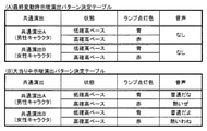
前記第1示唆の実行態様(例えば、最終変動時示唆演出の実行パターン)と、前記第2示唆の実行態様(例えば、大当り中示唆演出の実行パターン)とでは、一部の態様(例えば、スピーカ8L,8Rの音声出力)が異なる一方で他の態様(例えば、盤面ランプ48F050の点灯色)が共通する(例えば、図10-8参照)。
(5) In the gaming machine of (3) or (4) above,
The execution mode of the first suggestion (for example, the execution pattern of the suggestion effect at the time of the final fluctuation) and the execution mode of the second suggestion (for example, the execution pattern of the suggestion effect during the big hit) are some aspects (for example, the speaker). While the 8L and 8R audio outputs are different, other aspects (for example, the lighting color of the board lamp 48F050) are common (see, for example, FIG. 10-8).
このような構成によれば、遊技者が遊技機に対して状態示唆を行わせる際の状況に応じて、状態示唆の実行態様の一部が異なるため、状況に応じて適切に状態示唆を行うことができる。 According to such a configuration, since a part of the execution mode of the state suggestion differs depending on the situation when the player causes the gaming machine to suggest the state, the state suggestion is appropriately performed according to the situation. be able to.
(6) 上記(5)の遊技機において、
前記示唆手段は、
前記第1示唆(例えば、最終変動時示唆演出)を行う場合、前記第1示唆部(例えば、盤面ランプ48F050)を用いる一方で前記第2示唆部(例えば、スピーカ8L,8R)を用いず(例えば、図10-8(A),図10-9参照)、
前記第2示唆(例えば、大当り中示唆演出)を行う場合、第1示唆部(例えば、盤面ランプ48F050)および第2示唆部(例えば、スピーカ8L,8R)を用いる(例えば、図10-8(B),図10-11参照)。
(6) In the gaming machine of (5) above
The suggestion means
When the first suggestion (for example, the suggestion effect at the time of final fluctuation) is performed, the first suggestion section (for example, the board lamp 48F050) is used, but the second suggestion section (for example, the
When the second suggestion (for example, the suggestion effect during a big hit) is performed, the first suggestion section (for example, the board lamp 48F050) and the second suggestion section (for example, the
このような構成によれば、遊技者が遊技機に対して状態示唆を行わせる際の状況に応じて、状態示唆に用いられる示唆部の数が異なるため、状況に応じて適切に状態示唆を行うことができる。 According to such a configuration, the number of suggestion portions used for the state suggestion differs depending on the situation when the player causes the gaming machine to suggest the state. Therefore, the state suggestion is appropriately made according to the situation. It can be carried out.
(7) 上記(1)および(3)~(6)のいずれかの遊技機において、
前記特定期間において有利状態への制御が決定されている場合(例えば、大当り変動時)において、当該特定期間において前記動作検出手段によって遊技者の動作(例えば、裏動作)が検出されたときに、前記示唆手段による示唆の実行態様とは異なる態様で当該有利状態への制御を報知する有利報知手段(例えば、演出制御用CPU120による図10-4の48FS025で裏動作時大当り演出を実行する処理)をさらに備える(例えば、図10-10参照)。
(7) In any of the above (1) and (3) to (6) gaming machines.
When the control to the advantageous state is determined in the specific period (for example, when the jackpot fluctuates) and the movement of the player (for example, the back operation) is detected by the motion detecting means in the specific period. Advantageous notification means for notifying control of the advantageous state in a mode different from the execution mode of the suggestion by the suggestion means (for example, a process of executing a big hit effect during back operation with 48FS025 in FIG. 10-4 by the effect control CPU 120). (See, for example, FIG. 10-10).
このような構成によれば、有利状態への制御が決定されている場合、遊技者が状態示唆のための動作を行うことで有利状態への制御が報知されるため、遊技の興趣を向上させることができる。 According to such a configuration, when the control to the advantageous state is determined, the player performs an action for suggesting the state to notify the control to the advantageous state, which improves the interest of the game. be able to.
(8) 上記(2)~(7)のいずれかの遊技機において、
遊技者による選択によって前記共通演出の種類を決定する共通演出決定手段(例えば、演出制御用CPU120による遊技者の選択に基づき共通演出を決定する処理)をさらに備え、
前記共通演出のうち、前記共通演出決定手段によって第1共通演出(例えば、共通演出A)が決定された場合と第2共通演出(例えば、共通演出B)が決定された場合とでは、前記示唆手段による示唆における一部の態様(例えば、スピーカ8L,8Rの音声出力)が異なる一方で他の態様(例えば、盤面ランプ48F050の点灯色)が共通する(例えば、図10-8(B)参照)。
(8) In any of the gaming machines (2) to (7) above,
Further provided with a common effect determining means (for example, a process of determining a common effect based on the player's selection by the effect control CPU 120) for determining the type of the common effect by the player's selection.
Among the common effects, the above suggestion is obtained in the case where the first common effect (for example, common effect A) is determined by the common effect determining means and the case where the second common effect (for example, common effect B) is determined. While some aspects of the suggestion by means (eg, the audio output of the
このような構成によれば、遊技者によって選択された共通演出の種類に応じて、状態示唆の実行態様の一部が異なるため、遊技が多様になり、遊技の興趣が向上する。 According to such a configuration, since a part of the execution mode of the state suggestion is different depending on the type of the common effect selected by the player, the game is diversified and the interest of the game is improved.
[基本説明]
まず、パチンコ遊技機1の基本的な構成および制御(一般的なパチンコ遊技機の構成および制御でもある。)について説明する。
[Basic explanation]
First, the basic configuration and control of the pachinko gaming machine 1 (also the configuration and control of a general pachinko gaming machine) will be described.
(パチンコ遊技機1の構成など)
図1は、パチンコ遊技機1の正面図であり、主要部材の配置レイアウトを示す。パチンコ遊技機(遊技機)1は、大別して、遊技盤面を構成する遊技盤(ゲージ盤)2と、遊技盤2を支持固定する遊技機用枠(台枠)3とから構成されている。遊技盤2には、遊技領域が形成され、この遊技領域には、遊技媒体としての遊技球が、所定の打球発射装置から発射されて打ち込まれる。
(Configuration of
FIG. 1 is a front view of the
遊技盤2の所定位置(図1に示す例では、遊技領域の右側方)には、複数種類の特別識別情報としての特別図柄(特図ともいう)の可変表示(特図ゲームともいう)を行う第1特別図柄表示装置4Aおよび第2特別図柄表示装置4Bが設けられている。これらは、それぞれ、7セグメントのLEDなどからなる。特別図柄は、「0」~「9」を示す数字や「-」などの点灯パターンなどにより表される。特別図柄には、LEDを全て消灯したパターンが含まれてもよい。
A variable display (also referred to as a special figure game) of a special symbol (also referred to as a special figure) as a plurality of types of special identification information is displayed at a predetermined position of the game board 2 (in the example shown in FIG. 1, on the right side of the game area). The first special
なお、特別図柄の「可変表示」とは、例えば、複数種類の特別図柄を変動可能に表示することである(後述の他の図柄についても同じ)。変動としては、複数の図柄の更新表示、複数の図柄のスクロール表示、1以上の図柄の変形、1以上の図柄の拡大/縮小などがある。特別図柄や後述の普通図柄の変動では、複数種類の特別図柄または普通図柄が更新表示される。後述の飾り図柄の変動では、複数種類の飾り図柄がスクロール表示または更新表示されたり、1以上の飾り図柄が変形や拡大/縮小されたりする。なお、変動には、ある図柄を点滅表示する態様も含まれる。可変表示の最後には、表示結果として所定の特別図柄が停止表示(導出または導出表示などともいう)される(後述の他の図柄の可変表示についても同じ)。なお、可変表示を変動表示、変動と表現する場合がある。 The "variable display" of the special symbol is, for example, to display a plurality of types of special symbols in a variable manner (the same applies to other symbols described later). Variations include update display of a plurality of symbols, scroll display of a plurality of symbols, deformation of one or more symbols, enlargement / reduction of one or more symbols, and the like. In the variation of the special symbol or the ordinary symbol described later, a plurality of types of special symbols or ordinary symbols are updated and displayed. In the variation of the decorative symbol described later, a plurality of types of decorative symbols are scrolled or updated, and one or more decorative symbols are deformed or enlarged / reduced. It should be noted that the fluctuation includes a mode in which a certain symbol is blinking and displayed. At the end of the variable display, a predetermined special symbol is stopped and displayed (also referred to as derivation or derivation display) as a display result (the same applies to the variable display of other symbols described later). The variable display may be expressed as variable display or variable.
なお、第1特別図柄表示装置4Aにおいて可変表示される特別図柄を「第1特図」ともいい、第2特別図柄表示装置4Bにおいて可変表示される特別図柄を「第2特図」ともいう。また、第1特図を用いた特図ゲームを「第1特図ゲーム」といい、第2特図を用いた特図ゲームを「第2特図ゲーム」ともいう。なお、特別図柄の可変表示を行う特別図柄表示装置は1種類であってもよい。
The special symbol variably displayed on the first special
遊技盤2における遊技領域の中央付近には画像表示装置5が設けられている。画像表示装置5は、例えばLCD(液晶表示装置)や有機EL(Electro Luminescence)などから構成され、各種の演出画像を表示する。画像表示装置5は、プロジェクタおよびスクリーンから構成されていてもよい。画像表示装置5には、各種の演出画像が表示される。
An
例えば、画像表示装置5の画面上では、第1特図ゲームや第2特図ゲームと同期して、特別図柄とは異なる複数種類の装飾識別情報としての飾り図柄(数字などを示す図柄など)の可変表示が行われる。ここでは、第1特図ゲームまたは第2特図ゲームに同期して、「左」、「中」、「右」の各飾り図柄表示エリア5L、5C、5Rにおいて飾り図柄が可変表示(例えば上下方向のスクロール表示や更新表示)される。なお、同期して実行される特図ゲームおよび飾り図柄の可変表示を総称して単に可変表示ともいう。
For example, on the screen of the
画像表示装置5の画面上には、実行が保留されている可変表示に対応する保留表示や、実行中の可変表示に対応するアクティブ表示を表示するための表示エリアが設けられていてもよい。保留表示およびアクティブ表示を総称して可変表示に対応する可変表示対応表示ともいう。
On the screen of the
保留されている可変表示の数は保留記憶数ともいう。第1特図ゲームに対応する保留記憶数を第1保留記憶数、第2特図ゲームに対応する保留記憶数を第2保留記憶数ともいう。また、第1保留記憶数と第2保留記憶数との合計を合計保留記憶数ともいう。 The number of variable displays on hold is also called the number of hold storages. The number of reserved storage corresponding to the first special figure game is also referred to as the first reserved storage number, and the number of reserved storage corresponding to the second special figure game is also referred to as the second reserved storage number. Further, the total of the first reserved storage number and the second reserved storage number is also referred to as a total reserved storage number.
また、遊技盤2の所定位置には、複数のLEDを含んで構成された第1保留表示器25Aと第2保留表示器25Bとが設けられ、第1保留表示器25Aは、LEDの点灯個数によって、第1保留記憶数を表示し、第2保留表示器25Bは、LEDの点灯個数によって、第2保留記憶数を表示する。
Further, at a predetermined position of the
画像表示装置5の下方には、入賞球装置6Aと、可変入賞球装置6Bとが設けられている。
Below the
入賞球装置6Aは、例えば所定の玉受部材によって常に遊技球が進入可能な一定の開放状態に保たれる第1始動入賞口を形成する。第1始動入賞口に遊技球が進入したときには、所定個(例えば3個)の賞球が払い出されるとともに、第1特図ゲームが開始され得る。
The winning
可変入賞球装置6B(普通電動役物)は、ソレノイド81(図2参照)によって閉鎖状態と開放状態とに変化する第2始動入賞口を形成する。可変入賞球装置6Bは、例えば、一対の可動翼片を有する電動チューリップ型役物を備え、ソレノイド81がオフ状態であるときに可動翼片が垂直位置となることにより、当該可動翼片の先端が入賞球装置6Aに近接し、第2始動入賞口に遊技球が進入しない閉鎖状態になる(第2始動入賞口が閉鎖状態になるともいう。)。その一方で、可変入賞球装置6Bは、ソレノイド81がオン状態であるときに可動翼片が傾動位置となることにより、第2始動入賞口に遊技球が進入できる開放状態になる(第2始動入賞口が開放状態になるともいう。)。第2始動入賞口に遊技球が進入したときには、所定個(例えば3個)の賞球が払い出されるとともに、第2特図ゲームが開始され得る。なお、可変入賞球装置6Bは、閉鎖状態と開放状態とに変化するものであればよく、電動チューリップ型役物を備えるものに限定されない。
The variable winning
遊技盤2の所定位置(図1に示す例では、遊技領域の左右下方4箇所)には、所定の玉受部材によって常に一定の開放状態に保たれる一般入賞口10が設けられる。この場合には、一般入賞口10のいずれかに進入したときには、所定個数(例えば10個)の遊技球が賞球として払い出される。
At a predetermined position of the game board 2 (in the example shown in FIG. 1, four locations on the lower left and right sides of the game area), a general winning
入賞球装置6Aと可変入賞球装置6Bの下方には、大入賞口を有する特別可変入賞球装置7が設けられている。特別可変入賞球装置7は、ソレノイド82(図2参照)によって開閉駆動される大入賞口扉を備え、その大入賞口扉によって開放状態と閉鎖状態とに変化する特定領域としての大入賞口を形成する。
Below the winning
一例として、特別可変入賞球装置7では、大入賞口扉用(特別電動役物用)のソレノイド82がオフ状態であるときに大入賞口扉が大入賞口を閉鎖状態として、遊技球が大入賞口に進入(通過)できなくなる。その一方で、特別可変入賞球装置7では、大入賞口扉用のソレノイド82がオン状態であるときに大入賞口扉が大入賞口を開放状態として、遊技球が大入賞口に進入しやすくなる。
As an example, in the special variable winning
大入賞口に遊技球が進入したときには、所定個数(例えば14個)の遊技球が賞球として払い出される。大入賞口に遊技球が進入したときには、例えば第1始動入賞口や第2始動入賞口および一般入賞口10に遊技球が進入したときよりも多くの賞球が払い出される。
When a game ball enters the large prize opening, a predetermined number (for example, 14) of game balls are paid out as prize balls. When a game ball enters the large winning opening, more prize balls are paid out than when the game ball enters, for example, the first starting winning opening, the second starting winning opening, and the general winning
一般入賞口10を含む各入賞口に遊技球が進入することを「入賞」ともいう。特に、始動口(第1始動入賞口、第2始動入賞口始動口)への入賞を始動入賞ともいう。
The entry of a game ball into each winning opening including the general winning
遊技盤2の所定位置(図1に示す例では、遊技領域の左側方)には、普通図柄表示器2
0が設けられている。一例として、普通図柄表示器20は、7セグメントのLEDなどからなり、特別図柄とは異なる複数種類の普通識別情報としての普通図柄の可変表示を行う。普通図柄は、「0」~「9」を示す数字や「-」などの点灯パターンなどにより表される。普通図柄には、LEDを全て消灯したパターンが含まれてもよい。このような普通図柄の可変表示は、普図ゲームともいう。
At a predetermined position of the game board 2 (in the example shown in FIG. 1, the left side of the game area), the
0 is provided. As an example, the
画像表示装置5の左方には、遊技球が通過可能な通過ゲート41が設けられている。遊技球が通過ゲート41を通過したことに基づき、普図ゲームが実行される。
A passing
普通図柄表示器20の上方には、普図保留表示器25Cが設けられている。普図保留表示器25Cは、例えば4個のLEDを含んで構成され、実行が保留されている普図ゲームの数である普図保留記憶数をLEDの点灯個数により表示する。
Above the
遊技盤2の表面には、上記の構成以外にも、遊技球の流下方向や速度を変化させる風車および多数の障害釘が設けられている。遊技領域の最下方には、いずれの入賞口にも進入しなかった遊技球が取り込まれるアウト口が設けられている。
In addition to the above configuration, the surface of the
遊技機用枠3の左右上部位置には、効果音などを再生出力するためのスピーカ8L,8Rが設けられており、さらに遊技領域周辺部には、遊技効果用の遊技効果ランプ9が設けられている。遊技効果ランプ9は、LEDを含んで構成されている。
遊技盤2の所定位置(図1では図示略)には、演出に応じて動作する可動体32が設けられている。
At a predetermined position of the game board 2 (not shown in FIG. 1), a
遊技機用枠3の右下部位置には、遊技球を打球発射装置により遊技領域に向けて発射するために遊技者などによって操作される打球操作ハンドル(操作ノブ)30が設けられている。
At the lower right position of the
遊技領域の下方における遊技機用枠3の所定位置には、賞球として払い出された遊技球や所定の球貸機により貸し出された遊技球を、打球発射装置へと供給可能に保持(貯留)する打球供給皿(上皿)が設けられている。上皿の下方には、上皿満タン時に賞球が払い出される打球供給皿(下皿)が設けられている。
At a predetermined position of the
遊技領域の下方における遊技機用枠3の所定位置には、遊技者が把持して傾倒操作が可能なスティックコントローラ31Aが取り付けられている。スティックコントローラ31Aには、遊技者が押下操作可能なトリガボタンが設けられている。スティックコントローラ31Aに対する操作は、コントローラセンサユニット35A(図2参照)により検出される。
A
遊技領域の下方における遊技機用枠3の所定位置には、遊技者が押下操作などにより所定の指示操作を可能なプッシュボタン31Bが設けられている。プッシュボタン31Bに対する操作は、プッシュセンサ35B(図2参照)により検出される。
A
パチンコ遊技機1では、遊技者の動作(操作など)を検出する検出手段として、スティックコントローラ31Aやプッシュボタン31Bが設けられるが、これら以外の検出手段が設けられていてもよい。
The
(遊技の進行の概略)
パチンコ遊技機1が備える打球操作ハンドル30への遊技者による回転操作により、遊技球が遊技領域に向けて発射される。遊技球が通過ゲート41を通過すると、普通図柄表
示器20による普図ゲームが開始される。なお、前回の普図ゲームの実行中の期間などに遊技球が通過ゲート41を通過した場合(遊技球が通過ゲート41を通過したが当該通過に基づく普図ゲームを直ちに実行できない場合)には、当該通過に基づく普図ゲームは所定の上限数(例えば4)まで保留される。
(Outline of the progress of the game)
The game ball is launched toward the game area by the rotation operation of the
この普図ゲームでは、特定の普通図柄(普図当り図柄)が停止表示されれば、普通図柄の表示結果が「普図当り」となる。その一方、確定普通図柄として、普図当り図柄以外の普通図柄(普図ハズレ図柄)が停止表示されれば、普通図柄の表示結果が「普図ハズレ」となる。「普図当り」となると、可変入賞球装置6Bを所定期間開放状態とする開放制御が行われる(第2始動入賞口が開放状態になる)。
In this normal symbol game, if a specific normal symbol (design per normal symbol) is stopped and displayed, the display result of the normal symbol becomes "per normal symbol". On the other hand, if a normal symbol other than a normal symbol (a normal symbol lost symbol) is stopped and displayed as a confirmed normal symbol, the display result of the normal symbol becomes "normal symbol lost". When it becomes "per-normal", the opening control is performed so that the variable winning
入賞球装置6Aに形成された第1始動入賞口に遊技球が進入すると、第1特別図柄表示装置4Aによる第1特図ゲームが開始される。
When the game ball enters the first starting winning opening formed in the winning
可変入賞球装置6Bに形成された第2始動入賞口に遊技球が進入すると、第2特別図柄表示装置4Bによる第2特図ゲームが開始される。
When the game ball enters the second starting winning opening formed in the variable winning
なお、特図ゲームの実行中の期間や、後述する大当り遊技状態や小当り遊技状態に制御されている期間に、遊技球が始動入賞口へ進入(入賞)した場合(始動入賞が発生したが当該始動入賞に基づく特図ゲームを直ちに実行できない場合)には、当該進入に基づく特図ゲームは所定の上限数(例えば4)までその実行が保留される。 In addition, when the game ball enters (wins) the start winning opening during the period during which the special figure game is being executed, or during the period controlled by the big hit game state or the small hit game state described later (starting prize has occurred). If the special figure game based on the start prize cannot be executed immediately), the execution of the special figure game based on the approach is suspended up to a predetermined upper limit number (for example, 4).
特図ゲームにおいて、確定特別図柄として特定の特別図柄(大当り図柄、例えば「7」、後述の大当り種別に応じて実際の図柄は異なる。)が停止表示されれば、「大当り」となり、大当り図柄とは異なる所定の特別図柄(小当り図柄、例えば「2」)が停止表示されれば、「小当り」となる。また、大当り図柄や小当り図柄とは異なる特別図柄(ハズレ図柄、例えば「-」)が停止表示されれば「ハズレ」となる。 In the special symbol game, if a specific special symbol (big hit symbol, for example, "7", the actual symbol differs depending on the jackpot type described later) is stopped and displayed as a confirmed special symbol, it becomes "big hit" and the jackpot symbol. If a predetermined special symbol (small hit symbol, for example, "2") different from the above is stopped and displayed, it becomes "small hit". Further, if a special symbol (missing symbol, for example, "-") different from the big hit symbol or the small hit symbol is stopped and displayed, it becomes "missing".
特図ゲームでの表示結果が「大当り」になった後には、遊技者にとって有利な有利状態として大当り遊技状態に制御される。特図ゲームでの表示結果が「小当り」になった後には、小当り遊技状態に制御される。 After the display result in the special figure game becomes "big hit", it is controlled to the big hit game state as an advantageous state advantageous for the player. After the display result in the special figure game becomes "small hit", it is controlled to the small hit game state.
大当り遊技状態においては、遊技者は、遊技球を大入賞口に進入させることで、賞球を得ることができる。したがって、大当り遊技状態は、遊技者にとって有利な状態である。大当り遊技状態におけるラウンド数が多い程、また、開放上限期間が長い程遊技者にとって有利となる。 In the big hit game state, the player can obtain the prize ball by letting the game ball enter the big prize opening. Therefore, the jackpot gaming state is an advantageous state for the player. The larger the number of rounds in the jackpot game state and the longer the open upper limit period, the more advantageous it is for the player.
なお、「大当り」には、大当り種別が設定されている。例えば、大入賞口の開放態様(ラウンド数や開放上限期間)や、大当り遊技状態後の遊技状態(後述の、通常状態、時短状態、確変状態など)を複数種類用意し、これらに応じて大当り種別が設定されている。大当り種別として、多くの賞球を得ることができる大当り種別や、賞球の少ないまたはほとんど賞球を得ることができない大当り種別が設けられていてもよい。 A big hit type is set for "big hit". For example, multiple types of opening modes (number of rounds and opening upper limit period) of the big winning opening and game states after the big hit gaming state (normal state, time saving state, probability change state, etc., which will be described later) are prepared, and the big hit is made according to these. The type is set. As the big hit type, a big hit type in which a large number of prize balls can be obtained and a big hit type in which a small number of prize balls or almost no prize balls can be obtained may be provided.
小当り遊技状態では、特別可変入賞球装置7により形成される大入賞口が所定の開放態様で開放状態となる。例えば、小当り遊技状態では、一部の大当り種別のときの大当り遊技状態と同様の開放態様(大入賞口の開放回数が上記ラウンド数と同じであり、かつ、大入賞口の閉鎖タイミングも同じなど)で大入賞口が開放状態となる。なお、大当り種別と同様に、「小当り」にも小当り種別を設けてもよい。
In the small hit game state, the large winning opening formed by the special variable winning
大当り遊技状態が終了した後は、上記大当り種別に応じて、時短状態や確変状態に制御
されることがある。
After the jackpot game state is completed, it may be controlled to a time saving state or a probability change state according to the jackpot type.
時短状態では、平均的な特図変動時間(特図を変動させる期間)を通常状態よりも短縮させる制御(時短制御)が実行される。時短状態では、平均的な普図変動時間(普図を変動させる期間)を通常状態よりも短縮させたり、普図ゲームで「普図当り」となる確率を通常状態よりも向上させるなどにより、第2始動入賞口に遊技球が進入しやすくなる制御(高開放制御、高ベース制御)も実行される。時短状態は、特別図柄(特に第2特別図柄)の変動効率が向上する状態であるので、遊技者にとって有利な状態である。 In the time saving state, control (time saving control) is executed in which the average special figure fluctuation time (period in which the special figure is changed) is shortened from the normal state. In the time-saving state, the average fluctuation time of the normal map (the period during which the normal map is changed) is shortened from the normal state, and the probability of becoming a "normal map hit" in the normal map game is improved from the normal state. Control (high opening control, high base control) that makes it easier for the game ball to enter the second start winning opening is also executed. The time saving state is a state in which the variation efficiency of the special symbol (particularly the second special symbol) is improved, which is advantageous for the player.
確変状態(確率変動状態)では、時短制御に加えて、表示結果が「大当り」となる確率が通常状態よりも高くなる確変制御が実行される。確変状態は、特別図柄の変動効率が向上することに加えて「大当り」となりやすい状態であるので、遊技者にとってさらに有利な状態である。 In the probabilistic state (probability fluctuation state), in addition to the time saving control, the probability change control in which the probability that the display result becomes a "big hit" is higher than in the normal state is executed. The probabilistic state is a state in which the fluctuation efficiency of the special symbol is improved and the “big hit” is likely to occur, which is a more advantageous state for the player.
時短状態や確変状態は、所定回数の特図ゲームが実行されたことと、次回の大当り遊技状態が開始されたことなどといった、いずれか1つの終了条件が先に成立するまで継続する。所定回数の特図ゲームが実行されたことが終了条件となるものを、回数切り(回数切り時短、回数切り確変など)ともいう。 The time saving state and the probabilistic change state continue until any one of the end conditions such as the execution of the special figure game a predetermined number of times and the start of the next big hit game state are satisfied first. A game whose end condition is that the special figure game has been executed a predetermined number of times is also called a number-cutting (time-cutting time reduction, number-cutting probability change, etc.).
通常状態とは、遊技者にとって有利な大当り遊技状態などの有利状態、時短状態、確変状態などの特別状態以外の遊技状態のことであり、普図ゲームにおける表示結果が「普図当り」となる確率および特図ゲームにおける表示結果が「大当り」となる確率などのパチンコ遊技機1が、パチンコ遊技機1の初期設定状態(例えばシステムリセットが行われた場合のように、電源投入後に所定の復帰処理を実行しなかったとき)と同一に制御される状態である。
The normal state is a gaming state other than a special state such as an advantageous state such as a big hit gaming state which is advantageous for the player, a time saving state, and a probability change state, and the display result in the normal figure game is "normal figure hit". The
確変制御が実行されている状態を高確状態、確変制御が実行されていない状態を低確状態ともいう。時短制御が実行されている状態を高ベース状態、時短制御が実行されていない状態を低ベース状態ともいう。これらを組み合わせて、時短状態は低確高ベース状態、確変状態は高確高ベース状態、通常状態は低確低ベース状態などともいわれる。高確状態かつ低ベース状態は高確低ベース状態ともいう。 The state in which the probability change control is executed is also called a high probability state, and the state in which the probability change control is not executed is also called a low probability state. The state in which the time reduction control is executed is also called a high base state, and the state in which the time reduction control is not executed is also called a low base state. By combining these, it is also called a low-accuracy high-base state in a time-saving state, a high-accuracy high-base state in a probabilistic state, and a low-accuracy low-base state in a normal state. The high-accuracy state and the low-base state are also called the high-accuracy low-base state.
小当り遊技状態が終了した後は、遊技状態の変更が行われず、特図ゲームの表示結果が「小当り」となる以前の遊技状態に継続して制御される(但し、「小当り」発生時の特図ゲームが、上記回数切りにおける上記所定回数目の特図ゲームである場合には、当然遊技状態が変更される)。なお、特図ゲームの表示結果として「小当り」がなくてもよい。 After the small hit game state ends, the game state is not changed, and the game state is continuously controlled to the game state before the display result of the special figure game becomes "small hit" (however, "small hit" occurs. If the special figure game at the time is the special figure game of the predetermined number of times in the above number of times cut, the game state is naturally changed). In addition, it is not necessary that there is no "small hit" as the display result of the special figure game.
なお、遊技状態は、大当り遊技状態中に遊技球が特定領域(例えば、大入賞口内の特定領域)を通過したことに基づいて、変化してもよい。例えば、遊技球が特定領域を通過したとき、その大当り遊技状態後に確変状態に制御してもよい。 The gaming state may change based on the fact that the gaming ball has passed through a specific area (for example, a specific area in the big winning opening) during the big hit game state. For example, when the game ball passes through a specific area, it may be controlled to a probable change state after the big hit game state.
(演出の進行など)
パチンコ遊技機1では、遊技の進行に応じて種々の演出(遊技の進行状況を報知したり、遊技を盛り上げたりする演出)が実行される。当該演出について以下説明する。なお、当該演出は、画像表示装置5に各種の演出画像を表示することによって行われるが、当該表示に加えてまたは代えて、スピーカ8L,8Rからの音声出力、および/または、遊技効果ランプ9の点灯/消灯、可動体32の動作などにより行われてもよい。
(Progress of production, etc.)
In the
遊技の進行に応じて実行される演出として、画像表示装置5に設けられた「左」、「中」、「右」の飾り図柄表示エリア5L、5C、5Rでは、第1特図ゲームまたは第2特図
ゲームが開始されることに対応して、飾り図柄の可変表示が開始される。第1特図ゲームや第2特図ゲームにおいて表示結果(確定特別図柄ともいう。)が停止表示されるタイミングでは、飾り図柄の可変表示の表示結果となる確定飾り図柄(3つの飾り図柄の組合せ)も停止表示(導出)される。
As an effect executed according to the progress of the game, in the decorative
飾り図柄の可変表示が開始されてから終了するまでの期間では、飾り図柄の可変表示の態様が所定のリーチ態様となる(リーチが成立する)ことがある。ここで、リーチ態様とは、画像表示装置5の画面上にて停止表示された飾り図柄が後述の大当り組合せの一部を構成しているときに未だ停止表示されていない飾り図柄については可変表示が継続している態様などのことである。
In the period from the start to the end of the variable display of the decorative symbol, the variable display mode of the decorative symbol may become a predetermined reach mode (reach is established). Here, the reach mode is a variable display for a decorative symbol that has not yet been stopped and displayed when the decorative symbol that has been stopped and displayed on the screen of the
また、飾り図柄の可変表示中に上記リーチ態様となったことに対応してリーチ演出が実行される。パチンコ遊技機1では、演出態様に応じて表示結果(特図ゲームの表示結果や飾り図柄の可変表示の表示結果)が「大当り」となる割合(大当り信頼度、大当り期待度とも呼ばれる。)が異なる複数種類のリーチ演出が実行される。リーチ演出には、例えば、ノーマルリーチと、ノーマルリーチよりも大当り信頼度の高いスーパーリーチと、がある。
In addition, the reach effect is executed in response to the above-mentioned reach mode during the variable display of the decorative pattern. In the
特図ゲームの表示結果が「大当り」となるときには、画像表示装置5の画面上において、飾り図柄の可変表示の表示結果として、予め定められた大当り組合せとなる確定飾り図柄が導出される(飾り図柄の可変表示の表示結果が「大当り」となる)。一例として、「左」、「中」、「右」の飾り図柄表示エリア5L、5C、5Rにおける所定の有効ライン上に同一の飾り図柄(例えば、「7」など)が揃って停止表示される。
When the display result of the special figure game is "big hit", a definite decorative symbol that is a predetermined jackpot combination is derived as a display result of the variable display of the decorative symbol on the screen of the image display device 5 (decoration). The display result of the variable display of the symbol is "big hit"). As an example, the same decorative symbols (for example, "7") are all stopped and displayed on predetermined effective lines in the decorative
大当り遊技状態の終了後に確変状態に制御される「確変大当り」である場合には、奇数の飾り図柄(例えば、「7」など)が揃って停止表示され、大当り遊技状態の終了後に確変状態に制御されない「非確変大当り(通常大当り)」である場合には、偶数の飾り図柄(例えば、「6」など)が揃って停止表示されるようにしてもよい。この場合、奇数の飾り図柄を確変図柄、偶数の飾り図柄を非確変図柄(通常図柄)ともいう。非確変図柄でリーチ態様となった後に、最終的に「確変大当り」となる昇格演出を実行するようにしてもよい。 In the case of a "probability change jackpot" that is controlled to a probability change state after the end of the jackpot game state, an odd number of decorative symbols (for example, "7") are all stopped and displayed, and the probability change state is changed after the end of the jackpot game state. In the case of an uncontrolled "non-probability variable jackpot (normal jackpot)", an even number of decorative symbols (for example, "6") may be stopped and displayed. In this case, the odd-numbered decorative symbol is also referred to as a probabilistic symbol, and the even-numbered decorative symbol is also referred to as a non-probable variable symbol (normal symbol). After the non-probability pattern becomes the reach mode, the promotion effect that finally becomes the "probability change jackpot" may be executed.
特図ゲームの表示結果が「小当り」となるときには、画像表示装置5の画面上において、飾り図柄の可変表示の表示結果として、予め定められた小当り組合せとなる確定飾り図柄(例えば、「1 3 5」など)が導出される(飾り図柄の可変表示の表示結果が「小当り」となる)。一例として、「左」、「中」、「右」の飾り図柄表示エリア5L、5C、5Rにおける所定の有効ライン上にチャンス目を構成する飾り図柄が停止表示される。なお、特図ゲームの表示結果が、一部の大当り種別(小当り遊技状態と同様の態様の大当り遊技状態の大当り種別)の「大当り」となるときと、「小当り」となるときとで、共通の確定飾り図柄が導出表示されてもよい。
When the display result of the special figure game is "small hit", the fixed decorative symbol (for example, "for example,") which is a predetermined small hit combination as the display result of the variable display of the decorative symbol on the screen of the
特図ゲームの表示結果が「ハズレ」となる場合には、飾り図柄の可変表示の態様がリーチ態様とならずに、飾り図柄の可変表示の表示結果として、非リーチ組合せの確定飾り図柄(「非リーチハズレ」ともいう。)が停止表示される(飾り図柄の可変表示の表示結果が「非リーチハズレ」となる)ことがある。また、表示結果が「ハズレ」となる場合には、飾り図柄の可変表示の態様がリーチ態様となった後に、飾り図柄の可変表示の表示結果として、大当り組合せでない所定のリーチ組合せ(「リーチハズレ」ともいう)の確定飾り図柄が停止表示される(飾り図柄の可変表示の表示結果が「リーチハズレ」となる)こともある。 When the display result of the special figure game is "missing", the variable display mode of the decorative symbol is not the reach mode, and the display result of the variable display of the decorative symbol is a definite decorative symbol of a non-reach combination ("" (Also referred to as "non-reach loss") may be stopped and displayed (the display result of the variable display of the decorative pattern may be "non-reach loss"). In addition, when the display result is "missing", after the variable display mode of the decorative symbol becomes the reach mode, the display result of the variable display of the decorative symbol is a predetermined reach combination ("reach loss") that is not a big hit combination. The confirmed decorative symbol (also referred to as) may be stopped and displayed (the display result of the variable display of the decorative symbol may be "reach loss").
パチンコ遊技機1が実行可能な演出には、上記の可変表示対応表示(保留表示やアクティブ表示)を表示することも含まれる。また、他の演出として、例えば、大当り信頼度を予告する予告演出などが飾り図柄の可変表示中に実行される。予告演出には、実行中の可変表示における大当り信頼度を予告する予告演出や、実行前の可変表示(実行が保留されている可変表示)における大当り信頼度を予告する先読み予告演出がある。先読み予告演出として、可変表示対応表示(保留表示やアクティブ表示)の表示態様を通常とは異なる態様に変化させる演出が実行されるようにしてもよい。
The effect that the
また、画像表示装置5において、飾り図柄の可変表示中に飾り図柄を一旦仮停止させた後に可変表示を再開させることで、1回の可変表示を擬似的に複数回の可変表示のように見せる擬似連演出を実行するようにしてもよい。
Further, in the
大当り遊技状態中にも、大当り遊技状態を報知する大当り中演出が実行される。大当り中演出としては、ラウンド数を報知する演出や、大当り遊技状態の価値が向上することを示す昇格演出が実行されてもよい。また、小当り遊技状態中にも、小当り遊技状態を報知する小当り中演出が実行される。なお、小当り遊技状態中と、一部の大当り種別(小当り遊技状態と同様の態様の大当り遊技状態の大当り種別で、例えばその後の遊技状態を高確状態とする大当り種別)での大当り遊技状態とで、共通の演出を実行することで、現在が小当り遊技状態中であるか、大当り遊技状態中であるかを遊技者に分からないようにしてもよい。そのような場合であれば、小当り遊技状態の終了後と大当り遊技状態の終了後とで共通の演出を実行することで、高確状態であるか低確状態であるかを識別できないようにしてもよい。 Even during the big hit game state, the big hit middle effect that notifies the big hit game state is executed. As the big hit middle effect, an effect of notifying the number of rounds and a promotion effect indicating that the value of the big hit gaming state is improved may be executed. Further, even during the small hit game state, the small hit medium effect for notifying the small hit game state is executed. It should be noted that the big hit game during the small hit game state and in some big hit types (the big hit type of the big hit game state having the same aspect as the small hit game state, for example, the big hit type in which the subsequent game state is a highly accurate state). By executing a common effect depending on the state, the player may not know whether the current state is in the small hit game state or the big hit game state. In such a case, by executing a common effect after the end of the small hit game state and after the end of the big hit game state, it is not possible to distinguish between the high probability state and the low probability state. You may.
また、例えば特図ゲームなどが実行されていないときには、画像表示装置5にデモ(デモンストレーション)画像が表示される(客待ちデモ演出が実行される)。 Further, for example, when a special figure game or the like is not executed, a demo (demonstration) image is displayed on the image display device 5 (a customer waiting demo effect is executed).
(基板構成)
パチンコ遊技機1には、例えば図2に示すような主基板11、演出制御基板12、音声制御基板13、ランプ制御基板14、中継基板15などが搭載されている。その他にも、パチンコ遊技機1の背面には、例えば払出制御基板、情報端子基板、発射制御基板、電源基板などといった、各種の基板が配置されている。
(Board configuration)
For example, the
主基板11は、メイン側の制御基板であり、パチンコ遊技機1における上記遊技の進行(特図ゲームの実行(保留の管理を含む)、普図ゲームの実行(保留の管理を含む)、大当り遊技状態、小当り遊技状態、遊技状態など)を制御する機能を有する。主基板11は、遊技制御用マイクロコンピュータ100、スイッチ回路110、ソレノイド回路111などを有する。
The
主基板11に搭載された遊技制御用マイクロコンピュータ100は、例えば1チップのマイクロコンピュータであり、ROM(Read Only Memory)101と、RAM(Random Access Memory)102と、CPU(Central Processing Unit)103と、乱数回路104と、I/O(Input/Output port)105とを備える。
The
CPU103は、ROM101に記憶されたプログラムを実行することにより、遊技の進行を制御する処理(主基板11の機能を実現する処理)を行う。このとき、ROM101が記憶する各種データ(後述の変動パターン、後述の演出制御コマンド、後述の各種決定を行う際に参照される各種テーブルなどのデータ)が用いられ、RAM102がメインメモリとして使用される。RAM102は、その一部または全部がパチンコ遊技機1に対する電力供給が停止しても、所定期間記憶内容が保存されるバックアップRAMとなっている。なお、ROM101に記憶されたプログラムの全部または一部をRAM102に展
開して、RAM102上で実行するようにしてもよい。
The
乱数回路104は、遊技の進行を制御するときに使用される各種の乱数値(遊技用乱数)を示す数値データを更新可能にカウントする。遊技用乱数は、CPU103が所定のコンピュータプログラムを実行することで更新されるもの(ソフトウェアで更新されるもの)であってもよい。
The
I/O105は、例えば各種信号(後述の検出信号)が入力される入力ポートと、各種信号(第1特別図柄表示装置4A、第2特別図柄表示装置4B、普通図柄表示器20、第1保留表示器25A、第2保留表示器25B、普図保留表示器25Cなどを制御(駆動)する信号、ソレノイド駆動信号)を伝送するための出力ポートとを含んで構成される。
The I /
スイッチ回路110は、遊技球検出用の各種スイッチ(ゲートスイッチ21、始動口スイッチ(第1始動口スイッチ22Aおよび第2始動口スイッチ22B)、カウントスイッチ23)からの検出信号(遊技球が通過または進入してスイッチがオンになったことを示す検出信号など)を取り込んで遊技制御用マイクロコンピュータ100に伝送する。検出信号の伝送により、遊技球の通過または進入が検出されたことになる。
The
ソレノイド回路111は、遊技制御用マイクロコンピュータ100からのソレノイド駆動信号(例えば、ソレノイド81やソレノイド82をオンする信号など)を、普通電動役物用のソレノイド81や大入賞口扉用のソレノイド82に伝送する。
The
主基板11(遊技制御用マイクロコンピュータ100)は、遊技の進行の制御の一部として、遊技の進行に応じて演出制御コマンド(遊技の進行状況などを指定(通知)するコマンド)を演出制御基板12に供給する。主基板11から出力された演出制御コマンドは、中継基板15により中継され、演出制御基板12に供給される。当該演出制御コマンドには、例えば主基板11における各種の決定結果(例えば、特図ゲームの表示結果(大当り種別を含む。)、特図ゲームを実行する際に使用される変動パターン(詳しくは後述))、遊技の状況(例えば、可変表示の開始や終了、大入賞口の開放状況、入賞の発生、保留記憶数、遊技状態)、エラーの発生などを指定するコマンドなどが含まれる。
The main board 11 (
演出制御基板12は、主基板11とは独立したサブ側の制御基板であり、演出制御コマンドを受信し、受信した演出制御コマンドに基づいて演出(遊技の進行に応じた種々の演出であり、可動体32の駆動、エラー報知、電断復旧の報知などの各種報知を含む)を実行する機能を有する。
The
演出制御基板12には、演出制御用CPU120と、ROM121と、RAM122と、表示制御部123と、乱数回路124と、I/O125とが搭載されている。
The
演出制御用CPU120は、ROM121に記憶されたプログラムを実行することにより、表示制御部123とともに演出を実行するための処理(演出制御基板12の上記機能を実現するための処理であり、実行する演出の決定などを含む)を行う。このとき、ROM121が記憶する各種データ(各種テーブルなどのデータ)が用いられ、RAM122がメインメモリとして使用される。
The
演出制御用CPU120は、コントローラセンサユニット35Aやプッシュセンサ35Bからの検出信号(遊技者による操作を検出したときに出力される信号であり、操作内容を適宜示す信号)に基づいて演出の実行を表示制御部123に指示することもある。
The
表示制御部123は、VDP(Video Display Processor)、CGROM(Character G
enerator ROM)、VRAM(Video RAM)などを備え、演出制御用CPU120からの演出の実行指示に基づき、演出を実行する。
The
It is equipped with enerator ROM), VRAM (Video RAM), etc., and executes the effect based on the effect execution instruction from the
表示制御部123は、演出制御用CPU120からの演出の実行指示に基づき、実行する演出に応じた映像信号を画像表示装置5に供給することで、演出画像を画像表示装置5に表示させる。表示制御部123は、さらに、演出画像の表示に同期した音声出力や、遊技効果ランプ9の点灯/消灯を行うため、音指定信号(出力する音声を指定する信号)を音声制御基板13に供給したり、ランプ信号(ランプの点灯/消灯態様を指定する信号)をランプ制御基板14に供給したりする。また、表示制御部123は、可動体32を動作させる信号を当該可動体32または当該可動体32を駆動する駆動回路に供給する。
The
音声制御基板13は、スピーカ8L,8Rを駆動する各種回路を搭載しており、当該音指定信号に基づきスピーカ8L,8Rを駆動し、当該音指定信号が指定する音声をスピーカ8L,8Rから出力させる。
The
ランプ制御基板14は、遊技効果ランプ9を駆動する各種回路を搭載しており、当該ランプ信号に基づき遊技効果ランプ9を駆動し、当該ランプ信号が指定する態様で遊技効果ランプ9を点灯/消灯する。このようにして、表示制御部123は、音声出力、ランプの点灯/消灯を制御する。
The
なお、音声出力、ランプの点灯/消灯の制御(音指定信号やランプ信号の供給など)、可動体32の制御(可動体32を動作させる信号の供給など)は、演出制御用CPU120が実行するようにしてもよい。
The
乱数回路124は、各種演出を実行するために使用される各種の乱数値(演出用乱数)を示す数値データを更新可能にカウントする。演出用乱数は、演出制御用CPU120が所定のコンピュータプログラムを実行することで更新されるもの(ソフトウェアで更新されるもの)であってもよい。
The
演出制御基板12に搭載されたI/O125は、例えば主基板11などから伝送された演出制御コマンドを取り込むための入力ポートと、各種信号(映像信号、音指定信号、ランプ信号)を伝送するための出力ポートとを含んで構成される。
The I /
演出制御基板12、音声制御基板13、ランプ制御基板14といった、主基板11以外の基板をサブ基板ともいう。パチンコ遊技機1のようにサブ基板が機能別に複数設けられていてもよいし、1のサブ基板が複数の機能を有するように構成してもよい。
Boards other than the
(動作)
次に、パチンコ遊技機1の動作(作用)を説明する。
(motion)
Next, the operation (action) of the
(主基板11の主要な動作)
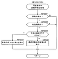
まず、主基板11における主要な動作を説明する。パチンコ遊技機1に対して電力供給が開始されると、遊技制御用マイクロコンピュータ100が起動し、CPU103によって遊技制御メイン処理が実行される。図3は、主基板11におけるCPU103が実行する遊技制御メイン処理を示すフローチャートである。
(Main operation of main board 11)
First, the main operation of the
図3に示す遊技制御メイン処理では、CPU103は、まず、割込禁止に設定する(ステップS1)。続いて、必要な初期設定を行う(ステップS2)。初期設定には、スタックポインタの設定、内蔵デバイス(CTC(カウンタ/タイマ回路)、パラレル入出力ポートなど)のレジスタ設定、RAM102をアクセス可能状態にする設定などが含まれる
。
In the game control main process shown in FIG. 3, the
次いで、クリアスイッチからの出力信号がオンであるか否かを判定する(ステップS3)。クリアスイッチは、例えば電源基板に搭載されている。クリアスイッチがオンの状態で電源が投入されると、出力信号(クリア信号)が入力ポートを介して遊技制御用マイクロコンピュータ100に入力される。クリアスイッチからの出力信号がオンである場合(ステップS3;Yes)、初期化処理(ステップS8)を実行する。初期化処理では、CPU103は、RAM102に記憶されるフラグ、カウンタ、バッファをクリアするRAMクリア処理を行い、作業領域に初期値を設定する。
Next, it is determined whether or not the output signal from the clear switch is ON (step S3). The clear switch is mounted on the power supply board, for example. When the power is turned on with the clear switch turned on, an output signal (clear signal) is input to the
また、CPU103は、初期化を指示する演出制御コマンドを演出制御基板12に送信する(ステップS9)。演出制御用CPU120は、当該演出制御コマンドを受信すると、例えば画像表示装置5において、遊技機の制御の初期化がなされたことを報知するための画面表示を行う。
Further, the
クリアスイッチからの出力信号がオンでない場合には(ステップS3;No)、RAM102(バックアップRAM)にバックアップデータが保存されているか否かを判定する(ステップS4)。不測の停電など(電断)によりパチンコ遊技機1への電力供給が停止したときには、CPU103は、当該電力供給の停止によって動作できなくなる直前に、電源供給停止時処理を実行する。この電源供給停止時処理では、RAM102にデータをバックアップすることを示すバックアップフラグをオンする処理、RAM102のデータ保護処理などが実行される。データ保護処理には、誤り検出符号(チェックサム、パリティビットなど)の付加、各種データをバックアップする処理が含まれる。バックアップされるデータには、遊技を進行するための各種データ(各種フラグ、各種タイマの状態などを含む)の他、前記バックアップフラグの状態や誤り検出符号も含まれる。ステップS4では、バックアップフラグがオンであるか否かを判定する。バックアップフラグがオフでRAM102にバックアップデータが記憶されていない場合(ステップS4;No)、初期化処理(ステップS8)を実行する。
If the output signal from the clear switch is not on (step S3; No), it is determined whether or not the backup data is stored in the RAM 102 (backup RAM) (step S4). When the power supply to the
RAM102にバックアップデータが記憶されている場合(ステップS4;Yes)、CPU103は、バックアップしたデータのデータチェックを行い(誤り検出符号を用いて行われる)、データが正常か否かを判定する(ステップS5)。ステップS5では、例えば、パリティビットやチェックサムにより、RAM102のデータが、電力供給停止時のデータと一致するか否かを判定する。これらが一致すると判定された場合、RAM102のデータが正常であると判定する。
When the backup data is stored in the RAM 102 (step S4; Yes), the
RAM102のデータが正常でないと判定された場合(ステップS5;No)、内部状態を電力供給停止時の状態に戻すことができないので、初期化処理(ステップS8)を実行する。
When it is determined that the data in the
RAM102のデータが正常であると判定された場合(ステップS5;Yes)、CPU103は、主基板11の内部状態を電力供給停止時の状態に戻すための復旧処理(ステップS6)を行う。復旧処理では、CPU103は、RAM102の記憶内容(バックアップしたデータの内容)に基づいて作業領域の設定を行う。これにより、電力供給停止時の遊技状態に復旧し、特別図柄の変動中であった場合には、後述の遊技制御用タイマ割込み処理の実行によって、復旧前の状態から特別図柄の変動が再開されることになる。
When it is determined that the data in the
そして、CPU103は、電断からの復旧を指示する演出制御コマンドを演出制御基板12に送信する(ステップS7)。これに合わせて、バックアップされている電断前の遊技状態を指定する演出制御コマンドや、特図ゲームの実行中であった場合には当該実行中
の特図ゲームの表示結果を指定する演出制御コマンドを送信するようにしてもよい。これらコマンドは、後述の特別図柄プロセス処理で送信設定されるコマンドと同じコマンドを使用できる。演出制御用CPU120は、電断からの復旧時を特定する演出制御コマンドを受信すると、例えば画像表示装置5において、電断からの復旧がなされたことまたは電断からの復旧中であることを報知するための画面表示を行う。演出制御用CPU120は、前記演出制御コマンドに基づいて、適宜の画面表示を行うようにしてもよい。
Then, the
復旧処理または初期化処理を終了して演出制御基板12に演出制御コマンドを送信した後には、CPU103は、乱数回路104を初期設定する乱数回路設定処理を実行する(ステップS10)。そして、所定時間(例えば2ms)毎に定期的にタイマ割込がかかるように遊技制御用マイクロコンピュータ100に内蔵されているCTCのレジスタの設定を行い(ステップS11)、割込みを許可する(ステップS12)。その後、ループ処理に入る。以後、所定時間(例えば2ms)ごとにCTCから割込み要求信号がCPU103へ送出され、CPU103は定期的にタイマ割込み処理を実行することができる。
After the restoration process or the initialization process is completed and the effect control command is transmitted to the
こうした遊技制御メイン処理を実行したCPU103は、CTCからの割込み要求信号を受信して割込み要求を受け付けると、図4のフローチャートに示す遊技制御用タイマ割込み処理を実行する。図4に示す遊技制御用タイマ割込み処理を開始すると、CPU103は、まず、所定のスイッチ処理を実行することにより、スイッチ回路110を介してゲートスイッチ21、第1始動口スイッチ22A、第2始動口スイッチ22B、カウントスイッチ23といった各種スイッチからの検出信号の受信の有無を判定する(ステップS21)。続いて、所定のメイン側エラー処理を実行することにより、パチンコ遊技機1の異常診断を行い、その診断結果に応じて必要ならば警告を発生可能とする(ステップS22)。この後、所定の情報出力処理を実行することにより、例えばパチンコ遊技機1の外部に設置されたホール管理用コンピュータに供給される大当り情報(大当りの発生回数などを示す情報)、始動情報(始動入賞の回数などを示す情報)、確率変動情報(確変状態となった回数などを示す情報)などのデータを出力する(ステップS23)。
When the
情報出力処理に続いて、主基板11の側で用いられる遊技用乱数の少なくとも一部をソフトウェアにより更新するための遊技用乱数更新処理を実行する(ステップS24)。この後、CPU103は、特別図柄プロセス処理を実行する(ステップS25)。CPU103がタイマ割込み毎に特別図柄プロセス処理を実行することにより、特図ゲームの実行および保留の管理や、大当り遊技状態や小当り遊技状態の制御、遊技状態の制御などが実現される(詳しくは後述)。
Following the information output process, a game random number update process for updating at least a part of the game random numbers used on the
特別図柄プロセス処理に続いて、普通図柄プロセス処理が実行される(ステップS26)。CPU103がタイマ割込み毎に普通図柄プロセス処理を実行することにより、ゲートスイッチ21からの検出信号に基づく(通過ゲート41に遊技球が通過したことに基づく)普図ゲームの実行および保留の管理や、「普図当り」に基づく可変入賞球装置6Bの開放制御などを可能にする。普図ゲームの実行は、普通図柄表示器20を駆動することにより行われ、普図保留表示器25Cを点灯させることにより普図保留数を表示する。
Following the special symbol process process, the normal symbol process process is executed (step S26). By executing the normal symbol process processing for each timer interrupt, the
普通図柄プロセス処理を実行した後、遊技制御用タイマ割込み処理の一部として、電断が発生したときの処理、賞球を払い出すための処理などが行われてもよい。その後、CPU103は、コマンド制御処理を実行する(ステップS27)。CPU103は、上記各処理にて演出制御コマンドを送信設定することがある。ステップS27のコマンド制御処理では、送信設定された演出制御コマンドを演出制御基板12などのサブ側の制御基板に対して伝送させる処理が行われる。コマンド制御処理を実行した後には、割込みを許可してから、遊技制御用タイマ割込み処理を終了する。
After executing the normal symbol process process, as a part of the game control timer interrupt process, a process when a power failure occurs, a process for paying out a prize ball, and the like may be performed. After that, the
図5は、特別図柄プロセス処理として、図4に示すステップS25にて実行される処理の一例を示すフローチャートである。この特別図柄プロセス処理において、CPU103は、まず、始動入賞判定処理を実行する(ステップS101)。
FIG. 5 is a flowchart showing an example of the process executed in step S25 shown in FIG. 4 as the special symbol process process. In this special symbol process process, the
始動入賞判定処理では、始動入賞の発生を検出し、RAM102の所定領域に保留情報を格納し保留記憶数を更新する処理が実行される。始動入賞が発生すると、表示結果(大当り種別を含む)や変動パターンを決定するための乱数値が抽出され、保留情報として記憶される。また、抽出した乱数値に基づいて、表示結果や変動パターンを先読み判定する処理が実行されてもよい。保留情報や保留記憶数を記憶した後には、演出制御基板12に始動入賞の発生、保留記憶数、先読み判定などの判定結果を指定するための演出制御コマンドを送信するための送信設定が行われる。こうして送信設定された始動入賞時の演出制御コマンドは、例えば特別図柄プロセス処理が終了した後、図4に示すステップS27のコマンド制御処理が実行されることなどにより、主基板11から演出制御基板12に対して伝送される。
In the start winning determination process, a process of detecting the occurrence of a start winning, storing the hold information in a predetermined area of the
S101にて始動入賞判定処理を実行した後、CPU103は、RAM102に設けられた特図プロセスフラグの値に応じて、ステップS110~S120の処理のいずれかを選択して実行する。なお、特別図柄プロセス処理の各処理(ステップS110~S120)では、各処理に対応した演出制御コマンドを演出制御基板12に送信するための送信設定が行われる。
After executing the start winning determination process in S101, the
ステップS110の特別図柄通常処理は、特図プロセスフラグの値が“0”(初期値)のときに実行される。この特別図柄通常処理では、保留情報の有無などに基づいて、第1特図ゲームまたは第2特図ゲームを開始するか否かの判定が行われる。また、特別図柄通常処理では、表示結果決定用の乱数値に基づき、特別図柄や飾り図柄の表示結果を「大当り」または「小当り」とするか否かや「大当り」とする場合の大当り種別を、その表示結果が導出表示される以前に決定(事前決定)する。さらに、特別図柄通常処理では、決定された表示結果に対応して、特図ゲームにおいて停止表示させる確定特別図柄(大当り図柄や小当り図柄、ハズレ図柄のいずれか)が設定される。その後、特図プロセスフラグの値が“1”に更新され、特別図柄通常処理は終了する。なお、第2特図を用いた特図ゲームが第1特図を用いた特図ゲームよりも優先して実行されるようにしてもよい(特図2優先消化ともいう)。また、第1始動入賞口および第2始動入賞口への遊技球の入賞順序を記憶し、入賞順に特図ゲームの開始条件を成立させるようにしてもよい(入賞順消化ともいう)。 The special symbol normal processing in step S110 is executed when the value of the special symbol process flag is “0” (initial value). In this special symbol normal processing, it is determined whether or not to start the first special figure game or the second special figure game based on the presence or absence of the reserved information. In addition, in the special symbol normal processing, whether or not the display result of the special symbol or decorative symbol is set to "big hit" or "small hit" based on the random number value for determining the display result, and the big hit type when the display result is set to "big hit". Is determined (predetermined) before the display result is derived and displayed. Further, in the special symbol normal processing, a definite special symbol (either a big hit symbol, a small hit symbol, or a lost symbol) to be stopped and displayed in the special symbol game is set according to the determined display result. After that, the value of the special symbol process flag is updated to "1", and the special symbol normal processing ends. It should be noted that the special figure game using the second special figure may be executed with priority over the special figure game using the first special figure (also referred to as special figure 2 priority digestion). Further, the winning order of the game balls to the first starting winning opening and the second starting winning opening may be stored, and the starting condition of the special figure game may be satisfied in the winning order (also referred to as winning order digestion).
乱数値に基づき各種の決定を行う場合には、ROM101に格納されている各種のテーブル(乱数値と比較される決定値が決定結果に割り当てられているテーブル)が参照される。主基板11における他の決定、演出制御基板12における各種の決定についても同じである。演出制御基板12においては、各種のテーブルがROM121に格納されている。
When making various decisions based on the random number value, various tables stored in the ROM 101 (a table in which the decision value to be compared with the random number value is assigned to the decision result) are referred to. The same applies to other decisions on the
ステップS111の変動パターン設定処理は、特図プロセスフラグの値が“1”のときに実行される。この変動パターン設定処理には、表示結果を「大当り」または「小当り」とするか否かの事前決定結果などに基づき、変動パターン決定用の乱数値を用いて変動パターンを複数種類のいずれかに決定する処理などが含まれている。変動パターン設定処理では、変動パターンを決定したときに、特図プロセスフラグの値が“2”に更新され、変動パターン設定処理は終了する。 The variation pattern setting process in step S111 is executed when the value of the special figure process flag is “1”. In this fluctuation pattern setting process, one of a plurality of types of fluctuation patterns is used using a random value for determining the fluctuation pattern based on the result of prior determination as to whether or not the display result is "big hit" or "small hit". It includes the process of determining. In the variation pattern setting process, when the variation pattern is determined, the value of the special figure process flag is updated to "2", and the variation pattern setting process ends.
変動パターンは、特図ゲームの実行時間(特図変動時間)(飾り図柄の可変表示の実行時間でもある)や、飾り図柄の可変表示の態様(リーチの有無など)、飾り図柄の可変表
示中の演出内容(リーチ演出の種類など)を指定するものであり、可変表示パターンとも呼ばれる。
The fluctuation pattern includes the execution time of the special figure game (special figure fluctuation time) (which is also the execution time of the variable display of the decorative symbol), the variable display mode of the decorative symbol (presence or absence of reach, etc.), and the variable display of the decorative symbol. It specifies the content of the effect (type of reach effect, etc.), and is also called a variable display pattern.
ステップS112の特別図柄変動処理は、特図プロセスフラグの値が“2”のときに実行される。この特別図柄変動処理には、第1特別図柄表示装置4Aや第2特別図柄表示装置4Bにおいて特別図柄を変動させるための設定を行う処理や、その特別図柄が変動を開始してからの経過時間を計測する処理などが含まれている。また、計測された経過時間が変動パターンに対応する特図変動時間に達したか否かの判定も行われる。そして、特別図柄の変動を開始してからの経過時間が特図変動時間に達したときには、特図プロセスフラグの値が“3”に更新され、特別図柄変動処理は終了する。
The special symbol variation process in step S112 is executed when the value of the special symbol process flag is “2”. In this special symbol variation processing, the processing for setting the special symbol to be varied in the first special
ステップS113の特別図柄停止処理は、特図プロセスフラグの値が“3”のときに実行される。この特別図柄停止処理には、第1特別図柄表示装置4Aや第2特別図柄表示装置4Bにて特別図柄の変動を停止させ、特別図柄の表示結果となる確定特別図柄を停止表示(導出)させるための設定を行う処理が含まれている。そして、表示結果が「大当り」である場合には特図プロセスフラグの値が“4”に更新される。その一方で、大当りフラグがオフであり、表示結果が「小当り」である場合には、特図プロセスフラグの値が“8”に更新される。また、表示結果が「ハズレ」である場合には、特図プロセスフラグの値が“0”に更新される。表示結果が「小当り」または「ハズレ」である場合、時短状態や確変状態に制御されているときであって、回数切りの終了成立する場合には、遊技状態も更新される。特図プロセスフラグの値が更新されると、特別図柄停止処理は終了する。
The special symbol stop process in step S113 is executed when the value of the special symbol process flag is “3”. In this special symbol stop process, the first special
ステップS114の大当り開放前処理は、特図プロセスフラグの値が“4”のときに実行される。この大当り開放前処理には、表示結果が「大当り」となったことなどに基づき、大当り遊技状態においてラウンドの実行を開始して大入賞口を開放状態とするための設定を行う処理などが含まれている。大入賞口を開放状態とするときには、大入賞口扉用のソレノイド82に対してソレノイド駆動信号を供給する処理が実行される。このときには、例えば大当り種別がいずれであるかに対応して、大入賞口を開放状態とする開放上限期間や、ラウンドの上限実行回数を設定する。これらの設定が終了すると、特図プロセスフラグの値が“5”に更新され、大当り開放前処理は終了する。
The jackpot opening preprocessing in step S114 is executed when the value of the special figure process flag is “4”. This big hit pre-opening process includes a process of setting to open the big winning opening by starting the execution of the round in the big hit game state based on the display result being "big hit". It has been. When the large winning opening is opened, a process of supplying a solenoid drive signal to the
ステップS115の大当り開放中処理は、特図プロセスフラグの値が“5”のときに実行される。この大当り開放中処理には、大入賞口を開放状態としてからの経過時間を計測する処理や、その計測した経過時間やカウントスイッチ23によって検出された遊技球の個数などに基づいて、大入賞口を開放状態から閉鎖状態に戻すタイミングとなったか否かを判定する処理などが含まれている。そして、大入賞口を閉鎖状態に戻すときには、大入賞口扉用のソレノイド82に対するソレノイド駆動信号の供給を停止させる処理などを実行した後、特図プロセスフラグの値が“6”に更新し、大当り開放中処理を終了する。
The process of opening the jackpot in step S115 is executed when the value of the special figure process flag is “5”. In this big hit opening process, the big winning opening is based on the process of measuring the elapsed time since the big winning opening is opened, the measured elapsed time, the number of game balls detected by the
ステップS116の大当り開放後処理は、特図プロセスフラグの値が“6”のときに実行される。この大当り開放後処理には、大入賞口を開放状態とするラウンドの実行回数が設定された上限実行回数に達したか否かを判定する処理や、上限実行回数に達した場合に大当り遊技状態を終了させるための設定を行う処理などが含まれている。そして、ラウンドの実行回数が上限実行回数に達していないときには、特図プロセスフラグの値が“5”に更新される一方、ラウンドの実行回数が上限実行回数に達したときには、特図プロセスフラグの値が“7”に更新される。特図プロセスフラグの値が更新されると、大当り解放後処理は終了する。 The post-processing after opening the jackpot in step S116 is executed when the value of the special figure process flag is “6”. In this big hit post-opening process, there is a process of determining whether or not the number of rounds to be executed with the big winning opening open has reached the set maximum number of executions, and a big hit game state when the maximum number of executions has been reached. It includes the process of making settings to terminate. Then, when the number of round executions has not reached the upper limit, the value of the special figure process flag is updated to "5", while when the number of round executions reaches the upper limit, the special figure process flag is set. The value is updated to "7". When the value of the special figure process flag is updated, the jackpot release post-processing ends.
ステップS117の大当り終了処理は、特図プロセスフラグの値が“7”のときに実行される。この大当り終了処理には、大当り遊技状態の終了を報知する演出動作としてのエ
ンディング演出が実行される期間に対応した待ち時間が経過するまで待機する処理や、大当り遊技状態の終了に対応して確変制御や時短制御を開始するための各種の設定を行う処理などが含まれている。こうした設定が行われたときには、特図プロセスフラグの値が“0”に更新され、大当り終了処理は終了する。
The jackpot end process of step S117 is executed when the value of the special figure process flag is “7”. In this jackpot end process, there is a process of waiting until the waiting time corresponding to the period corresponding to the period in which the ending effect as an effect effect for notifying the end of the jackpot game state is executed, and a probable change corresponding to the end of the jackpot game state. It includes processing to make various settings for starting control and time reduction control. When such a setting is made, the value of the special figure process flag is updated to "0", and the jackpot end process ends.
ステップS118の小当り開放前処理は、特図プロセスフラグの値が“8”のときに実行される。この小当り開放前処理には、表示結果が「小当り」となったことに基づき、小当り遊技状態において大入賞口を開放状態とするための設定を行う処理などが含まれている。このときには、特図プロセスフラグの値が“9”に更新され、小当り開放前処理は終了する。 The small hit release preprocessing in step S118 is executed when the value of the special figure process flag is “8”. This small hit pre-opening process includes a process of setting the large winning opening to be in the open state in the small hit game state based on the display result being "small hit". At this time, the value of the special figure process flag is updated to "9", and the small hit opening preprocessing ends.
ステップS119の小当り開放中処理は、特図プロセスフラグの値が“9”のときに実行される。この小当り開放中処理には、大入賞口を開放状態としてからの経過時間を計測する処理や、その計測した経過時間などに基づいて、大入賞口を開放状態から閉鎖状態に戻すタイミングとなったか否かを判定する処理などが含まれている。大入賞口を閉鎖状態に戻して小当り遊技状態の終了タイミングとなったときには、特図プロセスフラグの値が“10”に更新され、小当り開放中処理は終了する。 The small hit opening process in step S119 is executed when the value of the special figure process flag is “9”. In this small hit opening process, it is the timing to return the big prize opening from the open state to the closed state based on the process of measuring the elapsed time from the opening state of the big winning opening and the measured elapsed time. It includes processing to determine whether or not it is. When the large winning opening is returned to the closed state and the end timing of the small hit game state is reached, the value of the special figure process flag is updated to "10", and the processing during the small hit opening process ends.
ステップS120の小当り終了処理は、特図プロセスフラグの値が“10”のときに実行される。この小当り終了処理には、小当り遊技状態の終了を報知する演出動作が実行される期間に対応した待ち時間が経過するまで待機する処理などが含まれている。ここで、小当り遊技状態が終了するときには、小当り遊技状態となる以前のパチンコ遊技機1における遊技状態を継続させる。小当り遊技状態の終了時における待ち時間が経過したときには、特図プロセスフラグの値が“0”に更新され、小当り終了処理は終了する。
The small hit end process of step S120 is executed when the value of the special figure process flag is “10”. The small hit end process includes a process of waiting until a waiting time corresponding to a period in which the effect operation for notifying the end of the small hit game state is executed has elapsed. Here, when the small hit gaming state ends, the gaming state in the
(演出制御基板12の主要な動作)
次に、演出制御基板12における主要な動作を説明する。演出制御基板12では、電源基板などから電源電圧の供給を受けると、演出制御用CPU120が起動して、図6のフローチャートに示すような演出制御メイン処理を実行する。図6に示す演出制御メイン処理を開始すると、演出制御用CPU120は、まず、所定の初期化処理を実行して(ステップS71)、RAM122のクリアや各種初期値の設定、また演出制御基板12に搭載されたCTC(カウンタ/タイマ回路)のレジスタ設定などを行う。また、初期動作制御処理を実行する(ステップS72)。初期動作制御処理では、可動体32を駆動して初期位置に戻す制御、所定の動作確認を行う制御といった可動体32の初期動作を行う制御が実行される。
(Main operation of the effect control board 12)
Next, the main operation of the
その後、タイマ割込みフラグがオンとなっているか否かの判定を行う(ステップS73)。タイマ割込みフラグは、例えばCTCのレジスタ設定に基づき、所定時間(例えば2ミリ秒)が経過するごとにオン状態にセットされる。このとき、タイマ割込みフラグがオフであれば(ステップS73;No)、ステップS73の処理を繰り返し実行して待機する。 After that, it is determined whether or not the timer interrupt flag is turned on (step S73). The timer interrupt flag is set to the ON state every time a predetermined time (for example, 2 milliseconds) elapses, based on the register setting of the CTC, for example. At this time, if the timer interrupt flag is off (step S73; No), the process of step S73 is repeatedly executed and waits.
また、演出制御基板12の側では、所定時間が経過するごとに発生するタイマ割込みとは別に、主基板11からの演出制御コマンドを受信するための割込みが発生する。この割込みは、例えば主基板11からの演出制御INT信号がオン状態となることにより発生する割込みである。演出制御INT信号がオン状態となることによる割込みが発生すると、演出制御用CPU120は、自動的に割込み禁止に設定するが、自動的に割込み禁止状態にならないCPUを用いている場合には、割込み禁止命令(DI命令)を発行することが望ましい。演出制御用CPU120は、演出制御INT信号がオン状態となることによる割込みに対応して、例えば所定のコマンド受信割込み処理を実行する。このコマンド受信
割込み処理では、I/O125に含まれる入力ポートのうちで、中継基板15を介して主基板11から送信された制御信号を受信する所定の入力ポートより、演出制御コマンドを取り込む。このとき取り込まれた演出制御コマンドは、例えばRAM122に設けられた演出制御コマンド受信用バッファに格納する。その後、演出制御用CPU120は、割込み許可に設定してから、コマンド受信割込み処理を終了する。
Further, on the side of the
ステップS73にてタイマ割込みフラグがオンである場合には(ステップS73;Yes)、タイマ割込みフラグをクリアしてオフ状態にするとともに(ステップS74)、コマンド解析処理を実行する(ステップS75)。コマンド解析処理では、例えば主基板11の遊技制御用マイクロコンピュータ100から送信されて演出制御コマンド受信用バッファに格納されている各種の演出制御コマンドを読み出した後に、その読み出された演出制御コマンドに対応した設定や制御などが行われる。例えば、どの演出制御コマンドを受信したかや演出制御コマンドが特定する内容などを演出制御プロセス処理などで確認できるように、読み出された演出制御コマンドをRAM122の所定領域に格納したり、RAM122に設けられた受信フラグをオンしたりする。また、演出制御コマンドが遊技状態を特定する場合、遊技状態に応じた背景の表示を表示制御部123に指示してもよい。
If the timer interrupt flag is on in step S73 (step S73; Yes), the timer interrupt flag is cleared and turned off (step S74), and the command analysis process is executed (step S75). In the command analysis process, for example, after reading various effect control commands transmitted from the
ステップS75にてコマンド解析処理を実行した後には、演出制御プロセス処理を実行する(ステップS76)。演出制御プロセス処理では、例えば画像表示装置5の表示領域における演出画像の表示動作、スピーカ8L,8Rからの音声出力動作、遊技効果ランプ9および装飾用LEDといった装飾発光体における点灯動作、可動体32の駆動動作といった、各種の演出装置を動作させる制御が行われる。また、各種の演出装置を用いた演出動作の制御内容について、主基板11から送信された演出制御コマンドなどに応じた判定や決定、設定などが行われる。
After executing the command analysis process in step S75, the effect control process process is executed (step S76). In the effect control process processing, for example, an effect image display operation in the display area of the
ステップS76の演出制御プロセス処理に続いて、演出用乱数更新処理が実行され(ステップS77)、演出制御基板12の側で用いられる演出用乱数の少なくとも一部がソフトウェアにより更新される。その後、ステップS73の処理に戻る。ステップS73の処理に戻る前に、他の処理が実行されてもよい。
Following the effect control process process in step S76, the effect random number update process is executed (step S77), and at least a part of the effect random numbers used on the
図7は、演出制御プロセス処理として、図6のステップS76にて実行される処理の一例を示すフローチャートである。図7に示す演出制御プロセス処理において、演出制御用CPU120は、まず、先読予告設定処理を実行する(ステップS161)。先読予告設定処理では、例えば、主基板11から送信された始動入賞時の演出制御コマンドに基づいて、先読み予告演出を実行するための判定や決定、設定などが行われる。また、当該演出制御コマンドから特定される保留記憶数に基づき保留表示を表示するための処理が実行される。
FIG. 7 is a flowchart showing an example of the process executed in step S76 of FIG. 6 as the effect control process process. In the effect control process process shown in FIG. 7, the
ステップS161の処理を実行した後、演出制御用CPU120は、例えばRAM122に設けられた演出プロセスフラグの値に応じて、以下のようなステップS170~S177の処理のいずれかを選択して実行する。
After executing the process of step S161, the
ステップS170の可変表示開始待ち処理は、演出プロセスフラグの値が“0”(初期値)のときに実行される処理である。この可変表示開始待ち処理は、主基板11から可変表示の開始を指定するコマンドなどを受信したか否かに基づき、画像表示装置5における飾り図柄の可変表示を開始するか否かを判定する処理などを含んでいる。画像表示装置5における飾り図柄の可変表示を開始すると判定された場合、演出プロセスフラグの値を“1”に更新し、可変表示開始待ち処理を終了する。
The variable display start waiting process in step S170 is a process executed when the value of the effect process flag is “0” (initial value). This variable display start waiting process is a process of determining whether or not to start variable display of the decorative symbol on the
ステップS171の可変表示開始設定処理は、演出プロセスフラグの値が“1”のとき
に実行される処理である。この可変表示開始設定処理では、演出制御コマンドにより特定される表示結果や変動パターンに基づいて、飾り図柄の可変表示の表示結果(確定飾り図柄)、飾り図柄の可変表示の態様、リーチ演出や各種予告演出などの各種演出の実行の有無やその態様や実行開始タイミングなどを決定する。そして、その決定結果などを反映した演出制御パターン(表示制御部123に演出の実行を指示するための制御データの集まり)を設定する。その後、設定した演出制御パターンに基づいて、飾り図柄の可変表示の実行開始を表示制御部123に指示し、演出プロセスフラグの値を“2”に更新し、可変表示開始設定処理を終了する。表示制御部123は、飾り図柄の可変表示の実行開始の指示により、画像表示装置5において、飾り図柄の可変表示を開始させる。
The variable display start setting process in step S171 is a process executed when the value of the effect process flag is “1”. In this variable display start setting process, the display result of the variable display of the decorative symbol (fixed decorative symbol), the mode of the variable display of the decorative symbol, the reach effect, and various types are based on the display result and the variation pattern specified by the effect control command. It is determined whether or not various effects such as advance notice effects are executed, their modes, and the execution start timing. Then, an effect control pattern (a collection of control data for instructing the
ステップS172の可変表示中演出処理は、演出プロセスフラグの値が“2”のときに実行される処理である。この可変表示中演出処理において、演出制御用CPU120は、表示制御部123を指示することで、ステップS171にて設定された演出制御パターンに基づく演出画像を画像表示装置5の表示画面に表示させることや、可動体32を駆動させること、音声制御基板13に対する指令(効果音信号)の出力によりスピーカ8L,8Rから音声や効果音を出力させること、ランプ制御基板14に対する指令(電飾信号)の出力により遊技効果ランプ9や装飾用LEDを点灯/消灯/点滅させることといった、飾り図柄の可変表示中における各種の演出制御を実行する。こうした演出制御を行った後、例えば演出制御パターンから飾り図柄の可変表示終了を示す終了コードが読み出されたこと、あるいは、主基板11から確定飾り図柄を停止表示させることを指定するコマンドを受信したことなどに対応して、飾り図柄の表示結果となる確定飾り図柄を停止表示させる。確定飾り図柄を停止表示したときには、演出プロセスフラグの値が“3”に更新され、可変表示中演出処理は終了する。
The variable display effect process in step S172 is a process executed when the value of the effect process flag is “2”. In this variable display effect processing, the
ステップS173の特図当り待ち処理は、演出プロセスフラグの値が“3”のときに実行される処理である。この特図当り待ち処理において、演出制御用CPU120は、主基板11から大当り遊技状態または小当り遊技状態を開始することを指定する演出制御コマンドの受信があったか否かを判定する。そして、大当り遊技状態または小当り遊技状態を開始することを指定する演出制御コマンドを受信したきに、そのコマンドが大当り遊技状態の開始を指定するものであれば、演出プロセスフラグの値を“6”に更新する。これに対して、そのコマンドが小当り遊技状態の開始を指定するものであれば、演出プロセスフラグの値を小当り中演出処理に対応した値である“4”に更新する。また、大当り遊技状態または小当り遊技状態を開始することを指定するコマンドを受信せずに、当該コマンドの受信待ち時間が経過したときには、特図ゲームにおける表示結果が「ハズレ」であったと判定して、演出プロセスフラグの値を初期値である“0”に更新する。演出プロセスフラグの値を更新すると、特図当り待ち処理を終了する。
The special figure hit waiting process in step S173 is a process executed when the value of the effect process flag is “3”. In this special figure hit waiting process, the
ステップS174の小当り中演出処理は、演出制御プロセスフラグの値が“4”のときに実行される処理である。この小当り中演出処理において、演出制御用CPU120は、例えば小当り遊技状態における演出内容に対応した演出制御パターンなどを設定し、その設定内容に基づく小当り遊技状態における各種の演出制御を実行する。また、小当り中演出処理では、例えば主基板11から小当り遊技状態を終了することを指定するコマンドを受信したことに対応して、演出プロセスフラグの値を小当り終了演出に対応した値である“5”に更新し、小当り中演出処理を終了する。
The small hit medium effect process in step S174 is a process executed when the value of the effect control process flag is “4”. In this small hit medium effect process, the
ステップS175の小当り終了演出処理は、演出制御プロセスフラグの値が“5”のときに実行される処理である。この小当り終了演出処理において、演出制御用CPU120は、例えば小当り遊技状態の終了などに対応した演出制御パターンなどを設定し、その設定内容に基づく小当り遊技状態の終了時における各種の演出制御を実行する。その後、演出プロセスフラグの値を初期値である“0”に更新し、小当り終了演出処理を終了する。
The small hit end effect process in step S175 is a process executed when the value of the effect control process flag is “5”. In this small hit end effect process, the
ステップS176の大当り中演出処理は、演出プロセスフラグの値が“6”のときに実行される処理である。この大当り中演出処理において、演出制御用CPU120は、例えば大当り遊技状態における演出内容に対応した演出制御パターンなどを設定し、その設定内容に基づく大当り遊技状態における各種の演出制御を実行する。また、大当り中演出処理では、例えば主基板11から大当り遊技状態を終了することを指定するコマンドを受信したことに対応して、演出制御プロセスフラグの値をエンディング演出処理に対応した値である“7”に更新し、大当り中演出処理を終了する。
The jackpot effect process in step S176 is a process executed when the value of the effect process flag is “6”. In this big hit middle effect processing, the
ステップS177のエンディング演出処理は、演出プロセスフラグの値が“7”のときに実行される処理である。このエンディング演出処理において、演出制御用CPU120は、例えば大当り遊技状態の終了などに対応した演出制御パターンなどを設定し、その設定内容に基づく大当り遊技状態の終了時におけるエンディング演出の各種の演出制御を実行する。その後、演出プロセスフラグの値を初期値である“0”に更新し、エンディング演出処理を終了する。
The ending effect process of step S177 is a process executed when the value of the effect process flag is “7”. In this ending effect processing, the
(基本説明の変形例)
この発明は、上記基本説明で説明したパチンコ遊技機1に限定されず、本発明の趣旨を逸脱しない範囲で、様々な変形および応用が可能である。
(Modified example of basic explanation)
The present invention is not limited to the
上記基本説明のパチンコ遊技機1は、入賞の発生に基づいて所定数の遊技媒体を景品として払い出す払出式遊技機であったが、遊技媒体を封入し入賞の発生に基づいて得点を付与する封入式遊技機であってもよい。
The
特別図柄の可変表示中に表示されるものは1種類の図柄(例えば、「-」を示す記号)だけで、当該図柄の表示と消灯とを繰り返すことによって可変表示を行うようにしてもよい。さらに可変表示中に当該図柄が表示されるものも、可変表示の停止時には、当該図柄が表示されなくてもよい(表示結果としては「-」を示す記号が表示されなくてもよい)。 Only one type of symbol (for example, a symbol indicating "-") is displayed during the variable display of the special symbol, and the variable display may be performed by repeating the display and extinguishing of the symbol. Further, even if the symbol is displayed during the variable display, the symbol may not be displayed when the variable display is stopped (the symbol indicating "-" may not be displayed as the display result).
上記基本説明では、遊技機としてパチンコ遊技機1を示したが、メダルが投入されて所定の賭け数が設定され、遊技者による操作レバーの操作に応じて複数種類の図柄を回転させ、遊技者によるストップボタンの操作に応じて図柄を停止させたときに停止図柄の組合せが特定の図柄の組み合わせになると、所定数のメダルが遊技者に払い出されるゲームを実行可能なスロット機(例えば、ビッグボーナス、レギュラーボーナス、RT、AT、ART、CZ(以下、ボーナスなど)のうち1以上を搭載するスロット機)にも本発明を適用可能である。
In the above basic explanation, the
本発明を実現するためのプログラムおよびデータは、パチンコ遊技機1に含まれるコンピュータ装置などに対して、着脱自在の記録媒体により配布・提供される形態に限定されるものではなく、予めコンピュータ装置などの有する記憶装置にインストールしておくことで配布される形態を採っても構わない。さらに、本発明を実現するためのプログラムおよびデータは、通信処理部を設けておくことにより、通信回線などを介して接続されたネットワーク上の、他の機器からダウンロードすることによって配布する形態を採っても構わない。
The program and data for realizing the present invention are not limited to the form of being distributed and provided by a detachable recording medium to the computer device included in the
そして、ゲームの実行形態も、着脱自在の記録媒体を装着することにより実行するものだけではなく、通信回線などを介してダウンロードしたプログラムおよびデータを、内部メモリなどに一旦格納することにより実行可能とする形態、通信回線などを介して接続されたネットワーク上における、他の機器側のハードウェア資源を用いて直接実行する形態
としてもよい。さらには、他のコンピュータ装置などとネットワークを介してデータの交換を行うことによりゲームを実行するような形態とすることもできる。
The execution mode of the game is not limited to the one executed by attaching a detachable recording medium, but can be executed by temporarily storing the program and data downloaded via a communication line or the like in an internal memory or the like. It may be executed directly by using the hardware resources of other devices on the network connected via a communication line or the like. Furthermore, it is also possible to execute a game by exchanging data with another computer device or the like via a network.
なお、本明細書において、演出の実行割合などの各種割合の比較の表現(「高い」、「低い」、「異ならせる」などの表現)は、一方が「0%」の割合であることを含んでもよい。例えば、一方が「0%」の割合で、他方が「100%」の割合または「100%」未満の割合であることも含む。 In this specification, one of the expressions for comparison of various ratios such as the execution ratio of the production (expressions such as "high", "low", and "differentiate") is "0%". It may be included. For example, one may have a percentage of "0%" and the other a percentage of "100%" or less than "100%".
[本実施形態の特徴部207SGに関する説明]
上述したパチンコ遊技機1において、以下のような観点で課題が生じる場合がある。従来から、設定値変更機能付きパチンコ遊技機として、例えば、特開2010-200902号公報に記載されているものがある。しかしながら、特開2010-200902号公報に記載されている遊技機にあっては、設定状態であることが液晶画面でのみ報知されるため、設定状態であることの報知を好適に行うことができないという問題があった。このような課題を解決する発明207SGに係る遊技機を以下に提案する。また、特開2010-200902号公報に記載されている遊技機にあっては、設定状態において所定のエラーが発生したことを好適に放置することができないという問題があった。このような課題を解決する発明208SGに係る遊技機を以下に提案する。さらに、従来から、付与される遊技価値に関する所定情報を表示可能な情報表示手段を備えるパチンコ遊技機として、例えば、特許第6209653号公報に記載されているものがある。しかしながら、特開2010-200902号公報に記載されているパチンコ遊技機に特許第6209653号公報に記載されている情報表示手段を適用する場合、設定値を確認するための表示部と情報表示手段とを個別に設けると遊技機のコストを低減できないという問題があった。このような課題を解決する発明209SGに係る遊技機を以下に提案する。なお、以下では、発明207SG、発明208SG、および発明209SGに係る遊技機の特徴を、特徴部207SGとして表す。特徴部207SGは、上述したパチンコ遊技機1に適用可能である。
[Explanation of Feature 207SG of the Present Embodiment]
In the above-mentioned
図8-1は、本実施の形態の特徴部207SGにおけるパチンコ遊技機1の正面図であり、主要部材の配置レイアウトを示す。図8-1および図8-7に示すように、パチンコ遊技機(遊技機)1は、大別して、縦長の方形枠状に形成された外枠207SG001aと、遊技盤面を構成する遊技盤(ゲージ盤)2と、遊技盤2を支持固定する遊技機用枠(台枠)207SG003とから構成されている。遊技盤2には、遊技領域が形成され、この遊技領域には、遊技媒体としての遊技球が所定の打球発射装置から発射されて打ち込まれる。また、遊技機用枠207SG003には、ガラス窓を有するガラス扉枠207SG003aが左側辺を中心として遊技機用枠207SG003の前面を開放する扉開放位置と該前面を閉鎖する扉閉鎖位置との間で回動可能に設けられ、該ガラス扉枠207SG003aにより遊技領域を開閉できるようになっており、ガラス扉枠207SG003aを閉鎖したときにガラス窓を通して遊技領域を透視できるようになっている。
FIG. 8-1 is a front view of the
また、遊技機用枠207SG003は、遊技場の店員などが所有する扉キーを図示しない錠前に挿入して解錠することで開放可能となり、店員以外の遊技者などは遊技機用枠207SG003およびガラス扉枠207SG003aを開放することはできないようになっている。 Further, the gaming machine frame 207SG003 can be opened by inserting a door key owned by a game hall clerk into a lock (not shown) and unlocking it, and a player other than the clerk can open the gaming machine frame 207SG003 and glass. The door frame 207SG003a cannot be opened.
また、図8-1に示すように、パチンコ遊技機(遊技機)1の遊技盤2における画像表示装置5の左側は、遊技球が流下可能な左遊技領域207SG002Lに形成されており、遊技盤2における画像表示装置5の右側は、遊技球が流下可能な右遊技領域207SG002Rに形成されている。
Further, as shown in FIG. 8-1, the left side of the
左遊技領域207SG002Lは、打球操作ハンドル30の操作によって比較的弱く打ち出された(左打ち)遊技球が流下する遊技領域であり、右遊技領域207SG002Rは、打球操作ハンドル30の操作によって左遊技領域207SG002Lを流下する遊技球よりも強く打ち出された(右打ち)遊技球が、画像表示装置5の上方経路207SG002Cを通過して流下する遊技領域である。
The left game area 207SG002L is a game area in which the (left-handed) game ball launched relatively weakly by the operation of the hitting ball operation handle 30 flows down, and the right game area 207SG002R is the left game area 207SG002L by the operation of the hitting ball operation handle 30. This is a game area in which a game ball launched (right-handed) stronger than the game ball flowing down passes through the upper path 207SG002C of the
また、左遊技領域207SG002Lには、一般入賞口10が配置されており、右遊技領域207SG002Rには、該右遊技領域207SG002Rの上流方から下流側にかけて、通過ゲート41、可変入賞球装置6B、一般入賞口10、特別可変入賞球装置7が配置されている。つまり、左遊技領域207SG002Lを流下する遊技球は、一般入賞口10と入賞球装置6Aが形成する第1始動入賞口に入賞可能となっており、右遊技領域207SG002Rを流下する遊技球は、可変入賞球装置6Bが形成する第2始動入賞口、一般入賞口10および特別可変入賞球装置7が形成する大入賞口に入賞可能となっているとともに、通過ゲート41を通過可能となっている。
Further, a general winning
図8-1に示すように、入賞球装置6Aと可変入賞球装置6Bおよび特別可変入賞球装置7の間には、複数の障害釘207SGK1が配設されている。このため、左遊技領域207SG002Lを流下する遊技球は、第2始動入賞口や大入賞口に入賞不能であるとともに、右遊技領域207SG002Rを流下する遊技球は、第1始動入賞口に入賞不能となっている。
As shown in FIG. 8-1, a plurality of obstacle nails 207SGK1 are arranged between the winning
図8-2および図8-7に示すように、本実施の形態の特徴部207SGにおける主基板11は、第1部材と第2部材とにより開放可能に構成された基板ケース207SG201に収納された状態でパチンコ遊技機1の背面に搭載されている。また、主基板11には、パチンコ遊技機1の設定値を変更可能な設定値変更状態に切り替えるための錠スイッチ207SG051と、設定値変更状態において後述する大当りの当選確率(出玉率)などの設定値を変更するための設定スイッチとして機能する設定切替スイッチ207SG052と、遊技機用枠207SG003の開放を検知する開放センサ207SG090と、が設けられている。なお、詳細は後述するが、本実施の形態の特徴部207SGにおける設定値変更状態は、遊技場の店員などがパチンコ遊技機1に設定されている設定値を確認可能な状態(設定値確認状態)でもある。
As shown in FIGS. 8-2 and 8-7, the
これら錠スイッチ207SG051および設定切替スイッチ207SG052といった遊技者が操作可能な操作部が設けられた設定切替本体部は、主基板11とともに基板ケース207SG201内に収容されており、錠スイッチ207SG051および設定切替スイッチ207SG052は、基板ケース207SG201を開放しなくても操作可能となるように基板ケース207SG201の背面に形成された開口を介して背面側に露出している。
The setting switching main body unit provided with an operation unit that can be operated by the player, such as the lock switch 207SG051 and the setting changeover switch 207SG052, is housed in the board case 207SG201 together with the
錠スイッチ207SG051および設定切替スイッチ207SG052を有する基板ケース207SG201は、パチンコ遊技機1の背面に設けられているため、遊技機用枠207SG003を閉鎖した状態では操作が極めて困難であり、所定の扉キーを用いて遊技機用枠207SG003を開放することで操作が可能となる。また、錠スイッチ207SG051は、遊技場の店員などが所有する設定キーの操作を要することから、設定キーを所持する店員のみ操作が可能とされている。また、錠スイッチ207SG051は、設定キーによって、後述するONとOFFの切替操作を実行可能なスイッチでもある。なお、本実施の形態の特徴部207SGでは、扉キーと設定キーとが別個のキーである形態を例示しているが、これらは1のキーにて兼用されていてもよい。
Since the board case 207SG201 having the lock switch 207SG051 and the setting changeover switch 207SG052 is provided on the back surface of the
また、基板ケース207SG201には、設定値や後述するベース値を表示可能な表示
モニタ207SG029が配置されている。該表示モニタ207SG029は、主基板11に接続されているとともに、基板ケース207SG201の上部に配置されている。つまり、表示モニタ207SG029は、基板ケース207SG201における主基板11を視認する際の正面に配置されている。主基板11は、遊技機用枠207SG003を開放していない状態では視認できないので、主基板11を視認する際の正面とは、遊技機用枠207SG003を開放した状態における遊技盤2の裏面側を視認する際の正面であり、パチンコ遊技機1の正面とは異なる。ただし、主基板11を視認する際の正面とパチンコ遊技機1の正面とが共通するようにしてもよい。
Further, a display monitor 207SG029 capable of displaying a set value and a base value described later is arranged on the board case 207SG201. The display monitor 207SG029 is connected to the
また、図8-1および図8-2に示すように、本実施の形態の特徴部207SGにおけるパチンコ遊技機1の遊技盤2の所定位置(例えば、遊技領域の左下方位置)には、第1特図の変動表示を実行可能な第1特別図柄表示装置207SG004A、第2特図の変動表示を実行可能な第2特別図柄表示装置207SG004B、第1保留記憶数を表示可能な第1保留表示器207SG025A、第2保留記憶数を表示可能な第2保留表示器207SG025B、普通図柄の変動表示を実行可能な普通図柄表示器207SG020、普図保留記憶数を表示可能な普図保留表示器207SG025C、大当り遊技中に当該大当り遊技のラウンド数(大当り種別)を表示可能なラウンド表示器207SG131、高ベース状態(時短状態)や大当り遊技状態などの遊技球を右遊技領域207SG002Rに向けて打ち出す遊技状態において点灯する右打ちランプ207SG132、確変状態であるとき点灯する確変ランプ207SG133、高ベース状態(時短状態)において点灯する時短ランプ207SG134が纏めて配置されている遊技情報表示部207SG200が設けられている。
Further, as shown in FIGS. 8-1 and 8-2, a predetermined position (for example, a lower left position of the gaming area) of the
図8-3および図8-4に示すように、第1特別図柄表示装置207SG004Aと第2特別図柄表示装置207SG004Bとは、それぞれ8セグメントのLEDから構成されている。また、第1特別図柄表示装置207SG004Aと第2特別図柄表示装置207SG004Bとでは、特別図柄の変動表示結果がハズレや小当りである場合は、共通の組合せで該変動表示結果を導出表示可能となっている。 As shown in FIGS. 8-3 and 8-4, the first special symbol display device 207SG004A and the second special symbol display device 207SG004B are each composed of 8-segment LEDs. Further, in the first special symbol display device 207SG004A and the second special symbol display device 207SG004B, if the variation display result of the special symbol is a loss or a small hit, the variation display result can be derived and displayed by a common combination. ing.
第1特別図柄の変動表示において該変動表示結果が大当りとなる場合について、第1特別図柄表示装置207SG004Aは、大当り種別毎に2種類の大当り図柄(点灯するLEDの組合せ)にて変動表示結果と導出表示可能となっている。また、第2特別図柄の変動表示において該変動表示結果が大当りとなる場合について、第2特別図柄表示装置207SG004Bは、大当り種別毎に2種類の大当り図柄(点灯するLEDの組合せ)にて変動表示結果と導出表示可能となっている。 When the variation display result of the first special symbol is a big hit, the first special symbol display device 207SG004A uses two types of jackpot symbols (combination of lit LEDs) for each jackpot type to display the variation display result. Derived display is possible. Further, in the case where the variation display result is a big hit in the variation display of the second special symbol, the second special symbol display device 207SG004B displays the variation with two types of jackpot symbols (combination of lit LEDs) for each jackpot type. The result and derivation can be displayed.
なお、本実施の形態の特徴部207SGにおいては、第1特別図柄表示装置207SG004Aと第2特別図柄表示装置207SG004Bとで導出表示可能な大当り図柄は全て異なっているが、第1特別図柄表示装置207SG004Aで導出表示可能な大当り図柄と第2特別図柄表示装置207SG004Bで導出表示可能な大当り図柄は少なくとも一部が重複していてもよい。 In the feature unit 207SG of the present embodiment, the jackpot symbols that can be derived and displayed by the first special symbol display device 207SG004A and the second special symbol display device 207SG004B are all different, but the first special symbol display device 207SG004A At least a part of the jackpot symbol that can be derived and displayed in the above and the jackpot symbol that can be derived and displayed by the second special symbol display device 207SG004B may overlap.
図8-5に示すように、第1保留表示器207SG025Aと第2保留表示器207SG025Bとは、それぞれ4セグメントのLEDが左右方向に並列して配置されている。これら第1保留表示器207SG025Aと第2保留表示器207SG025Bとでは、保留記憶数が1個であれば左端部のLEDのみが点灯し、保留記憶数が増加していく毎に左から2番目、左から3番目、左から4番目のLEDが順次点灯する。そして、変動表示が実行される毎に、保留記憶が減少する(消費される)ことに応じて、該変動表示に対応する保留表示器でのLEDが所定のシフト方向(本実施の形態の特徴部207SGでは左方向)に向けて消灯していく。 As shown in FIG. 8-5, the first hold indicator 207SG025A and the second hold indicator 207SG025B each have four segments of LEDs arranged side by side in the left-right direction. In these first hold display 207SG025A and second hold display 207SG025B, if the number of hold storage is one, only the LED at the left end is lit, and each time the number of hold storage increases, it is the second from the left. The third LED from the left and the fourth LED from the left light up in sequence. Then, each time the variable display is executed, the LED on the hold display corresponding to the variable display is set in a predetermined shift direction (characteristic of the present embodiment) in response to the decrease (consumption) of the reserved memory. In the unit 207SG, the light is turned off toward the left side).
なお、本実施の形態の特徴部207SGでは、第1特図保留記憶と第2特図保留記憶とが両方存在する場合は、第2特図保留記憶にもとづく変動表示が優先して実行される様になっている。このため、図8-6に示すように、例えば第1特図保留記憶が1個存在するとともに第2特図保留記憶が2個存在する場合(第1保留表示器207SG025Aの左端部のLEDのみが点灯しているとともに、第2保留表示器207SG25Bの左2個のLEDが点灯している場合)は、第2特図保留記憶にもとづく変動表示の実行によって第2特図保留記憶が0個となった後に、第1特図保留記憶にもとづく変動表示が実行される。 In the feature unit 207SG of the present embodiment, when both the first special figure holding storage and the second special figure holding storage exist, the variable display based on the second special figure holding storage is preferentially executed. It has become like. Therefore, as shown in FIG. 8-6, for example, when there is one first special figure holding memory and two second special figure holding storages (only the LED at the left end of the first holding indicator 207SG025A). Is lit and the two LEDs on the left of the second hold indicator 207SG25B are lit), the second special figure hold memory is 0 due to the execution of the variable display based on the second special figure hold memory. After that, the variable display based on the first special figure hold storage is executed.
また、図8-6に示すように、ラウンド表示器207SG131は5個のセグメント(LED)から構成されている。なお、本実施の形態の特徴部207SGにおける大当り種別としては、5ラウンド大当りである大当りA、10ラウンド大当りである大当りB、15ラウンド大当りである大当りCの計3個の大当り種別が設けられており、これら大当り種別に応じてラウンド表示器207SG131を構成するセグメントのうちいずれのセグメントが点灯するかが異なっている。 Further, as shown in FIG. 8-6, the round display 207SG131 is composed of five segments (LEDs). As the big hit types in the feature unit 207SG of the present embodiment, a total of three big hit types are provided: a big hit A which is a 5-round big hit, a big hit B which is a 10-round big hit, and a big hit C which is a 15-round big hit. Therefore, which segment of the segments constituting the round display 207SG131 is lit differs depending on the type of jackpot.
主基板11から演出制御基板12に向けて伝送される制御信号は、中継基板15によって中継される。中継基板15を介して主基板11から演出制御基板12に対して伝送される制御コマンドは、例えば電気信号として送受信される演出制御コマンドである。演出制御コマンドには、例えば画像表示装置5における画像表示動作を制御するために用いられる表示制御コマンドや、スピーカ8L,8Rからの音声出力を制御するために用いられる音声制御コマンド、遊技効果ランプ9や装飾用LEDの点灯動作などを制御するために用いられるLED制御コマンドが含まれている。
The control signal transmitted from the
なお、本実施の形態の特徴部207SGにおける演出制御基板12には、変動表示中などにそれぞれの原点位置と演出位置との間で動作可能な第1可動体207SG321および第2可動体207SG322と、第1可動体207SG321が該第1可動体207SG321の原点位置に位置していることを検出可能な原点検出センサ207SG331と、第2可動体207SG322が該第2可動体207SG322の原点位置に位置していることを検出可能な原点検出センサ207SG332と、が接続されている。
The
図8-8(A)は、本実施の形態における特徴部207SGで用いられる演出制御コマンドの内容の一例を示す説明図である。演出制御コマンドは、例えば2バイト構成であり、1バイト目はMODE(コマンドの分類)を示し、2バイト目はEXT(コマンドの種類)を表す。MODEデータの先頭ビット(ビット7)は必ず「1」とされ、EXTデータの先頭ビットは「0」とされる。なお、図8-8(A)に示されたコマンド形態は一例であって、他のコマンド形態を用いてもよい。また、この例では、制御コマンドが2つの制御信号で構成されることになるが、制御コマンドを構成する制御信号数は、1であってもよいし、3以上の複数であってもよい。 FIG. 8-8 (A) is an explanatory diagram showing an example of the contents of the effect control command used in the feature unit 207SG in the present embodiment. The effect control command has, for example, a 2-byte configuration, the first byte represents MODE (command classification), and the second byte represents EXT (command type). The first bit (bit 7) of the MODE data is always "1", and the first bit of the EXT data is "0". The command form shown in FIG. 8-8 (A) is an example, and other command forms may be used. Further, in this example, the control command is composed of two control signals, but the number of control signals constituting the control command may be one or a plurality of three or more.
図8-8(A)に示す例において、コマンド8001Hは、第1特別図柄表示装置207SG004Aにおける第1特図を用いた特図ゲームにおける変動開始を指定する第1変動開始コマンドである。コマンド8002Hは、第2特別図柄表示装置207SG004Bにおける第2特図を用いた特図ゲームにおける変動開始を指定する第2変動開始コマンドである。コマンド81XXHは、特図ゲームにおける特別図柄の変動表示に対応して画像表示装置5における「左」、「中」、「右」の各飾り図柄表示エリア5L,5C,5Rで変動表示される飾り図柄などの変動パターン(変動時間)を指定する変動パターン指定コマンドである。ここで、XXHは不特定の16進数であることを示し、演出制御コマンドによる指示内容に応じて任意に設定される値であればよい。なお、変動パターン指定コ
マンドでは、指定する変動パターンなどに応じて、異なるEXTデータが設定される。
In the example shown in FIG. 8-8 (A), the command 8001H is a first variation start command for designating the variation start in the special figure game using the first special diagram in the first special symbol display device 207SG004A. The command 8002H is a second fluctuation start command for designating the fluctuation start in the special symbol game using the second special symbol in the second special symbol display device 207SG004B. The command 81XXH is a decoration that is variablely displayed in each of the "left", "middle", and "right" decorative
コマンド8CXXHは、変動表示結果通知コマンドであり、特別図柄や飾り図柄などの変動表示結果を指定する演出制御コマンドである。変動表示結果通知コマンドでは、例えば図8-8(B)に示すように、変動表示結果が「ハズレ」であるか「大当り」であるか「小当り」であるかの決定結果(事前決定結果)や、変動表示結果が「大当り」となる場合の大当り種別を複数種類のいずれとするかの決定結果(大当り種別決定結果)に応じて、異なるEXTデータが設定される。 The command 8CXXH is a variable display result notification command, and is an effect control command for designating a variable display result such as a special symbol or a decorative symbol. In the variation display result notification command, for example, as shown in FIG. 8-8 (B), the determination result (predetermined result) of whether the variation display result is "miss", "big hit", or "small hit". ) Or, different EXT data are set according to the determination result (big hit type determination result) of which of a plurality of types the jackpot type is to be used when the variable display result is "big hit".
変動表示結果通知コマンドでは、例えば図8-8(B)に示すように、コマンド8C00Hは、変動表示結果が「ハズレ」となる旨の事前決定結果を示す第1変動表示結果指定コマンドである。コマンド8C01Hは、変動表示結果が「大当り」で大当り種別が「大当りA」となる旨の事前決定結果および大当り種別決定結果を通知する第2変動表示結果指定コマンドである。コマンド8C02Hは、変動表示結果が「大当り」で大当り種別が「大当りB」となる旨の事前決定結果および大当り種別決定結果を通知する第3変動表示結果指定コマンドである。コマンド8C03Hは、変動表示結果が「大当り」で大当り種別が「大当りC」となる旨の事前決定結果および大当り種別決定結果を通知する第4変動表示結果指定コマンドである。コマンド8C04Hは、変動表示結果が「小当り」となる旨の事前決定結果を通知する第5変動表示結果指定コマンドである。 In the variation display result notification command, for example, as shown in FIG. 8-8 (B), the command 8C00H is a first variation display result designation command indicating a preliminary determination result that the variation display result is “missing”. The command 8C01H is a second variable display result designation command for notifying the pre-determined result that the variable display result is "big hit" and the big hit type is "big hit A" and the big hit type determination result. The command 8C02H is a third variable display result designation command for notifying the pre-determined result that the variable display result is "big hit" and the big hit type is "big hit B" and the big hit type determination result. The command 8C03H is a fourth variable display result designation command for notifying the pre-determined result that the variable display result is "big hit" and the big hit type is "big hit C" and the big hit type determination result. The command 8C04H is a fifth variable display result designation command for notifying a preliminary determination result that the variable display result is a "small hit".
コマンド8F00Hは、画像表示装置5における「左」、「中」、「右」の各飾り図柄表示エリア5L,5C,5Rで飾り図柄の変動停止(確定)を指定する図柄確定コマンドである。コマンド95XXHは、パチンコ遊技機1における現在の遊技状態を指定する遊技状態指定コマンドである。遊技状態指定コマンドでは、例えばパチンコ遊技機1における現在の遊技状態に応じて、異なるEXTデータが設定される。具体的な一例として、コマンド9500Hを時短制御が行われない遊技状態(低ベース状態、通常状態)に対応した第1遊技状態指定コマンドとし、コマンド9501Hを時短制御が行われる遊技状態(高ベース状態、時短状態)に対応した第2遊技状態指定コマンドとする。
The command 8F00H is a symbol confirmation command for designating the change stop (confirmation) of the decorative symbol in each of the “left”, “middle”, and “right” decorative
コマンド96XXHは、パチンコ遊技機1においてエラー(異常)の発生および発生したエラー(異常)の種別を指定するエラー(異常)指定コマンドである。エラー(異常)指定コマンドでは、例えば、各エラー(異常)に対応するEXTデータが設定されることにより、演出制御基板12側において、いずれのエラー(異常)の発生が判定されたのかを特定することができ、特定したエラー(異常)の発生が、後述するエラー報知処理によって報知される。
The command 96XXH is an error (abnormal) designation command that specifies the occurrence of an error (abnormality) and the type of the error (abnormality) that has occurred in the
コマンドA0XXHは、大当り遊技状態または小当り遊技状態の開始を示す演出画像の表示を指定する当り開始指定コマンド(「ファンファーレコマンド」ともいう)である。コマンドA1XXHは、大当り遊技状態または小当り遊技状態において、大入賞口が開放状態となっている期間であることを通知する大入賞口開放中通知コマンドである。コマンドA2XXHは、大当り遊技状態または小当り遊技状態において、大入賞口が開放状態から閉鎖状態に変化した期間であることを通知する大入賞口開放後通知コマンドである。コマンドA3XXHは、大当り遊技状態または小当り遊技状態の終了時における演出画像の表示を指定する当り終了指定コマンドである。 The command A0XXH is a hit start designation command (also referred to as a “fanfare command”) for designating the display of an effect image indicating the start of a big hit gaming state or a small hit gaming state. The command A1XXH is a big winning opening opening notification command for notifying that the big winning opening is in the open state in the big hit gaming state or the small hit gaming state. The command A2XXH is a notification command after opening the large winning opening that notifies that the period during which the large winning opening has changed from the open state to the closed state in the big hit gaming state or the small hit gaming state. The command A3XXH is a hit end designation command for designating the display of the effect image at the end of the big hit game state or the small hit game state.
当り開始指定コマンドや当り終了指定コマンドでは、例えば変動表示結果通知コマンドと同様のEXTデータが設定されることなどにより、事前決定結果や大当り種別決定結果に応じて異なるEXTデータが設定されてもよい。あるいは、当り開始指定コマンドや当り終了指定コマンドでは、事前決定結果および大当り種別決定結果と設定されるEXTデータとの対応関係を、変動表示結果通知コマンドにおける対応関係とは異ならせるように
してもよい。大入賞口開放中通知コマンドや大入賞口開放後通知コマンドでは、大当り遊技状態または小当り遊技状態におけるラウンドの実行回数(例えば「1」~「15」)に対応して、異なるEXTデータが設定される。
In the hit start designation command and the hit end designation command, different EXT data may be set according to the pre-determined result and the jackpot type determination result, for example, by setting the same EXT data as the variable display result notification command. .. Alternatively, in the hit start designation command or the hit end designation command, the correspondence between the pre-determined result and the jackpot type determination result and the set EXT data may be different from the correspondence in the variable display result notification command. .. In the notification command during the opening of the big winning opening and the notification command after opening the big winning opening, different EXT data are set according to the number of round executions (for example, "1" to "15") in the big hit game state or the small hit game state. Will be done.
コマンドB100Hは、入賞球装置6Aが形成する第1始動入賞口を通過(進入)した遊技球が第1始動口スイッチ22Aにより検出されて始動入賞(第1始動入賞)が発生したことに基づき、第1特別図柄表示装置207SG004Aにおける第1特図を用いた特図ゲームを実行するための第1始動条件が成立したことを通知する第1始動口入賞指定コマンドである。コマンドB200Hは、可変入賞球装置6Bが形成する第2始動入賞口を通過(進入)した遊技球が第2始動口スイッチ22Bにより検出されて始動入賞(第2始動入賞)が発生したことに基づき、第2特別図柄表示装置207SG004Bにおける第2特図を用いた特図ゲームを実行するための第2始動条件が成立したことを通知する第2始動口入賞指定コマンドである。
The command B100H is based on the fact that the game ball that has passed (entered) the first starting winning opening formed by the winning
コマンドC1XXHは、画像表示装置5などにて特図保留記憶数を特定可能に表示するために、第1特図保留記憶数を通知する第1保留記憶数通知コマンドである。コマンドC2XXHは、画像表示装置5などにて特図保留記憶数を特定可能に表示するために、第2特図保留記憶数を通知する第2保留記憶数通知コマンドである。第1保留記憶数通知コマンドは、例えば第1始動入賞口を遊技球が通過(進入)して第1始動条件が成立したことに基づいて、第1始動口入賞指定コマンドが送信されるときに、主基板11から演出制御基板12に対して送信される。第2保留記憶数通知コマンドは、例えば第2始動入賞口を遊技球が通過(進入)して第2始動条件が成立したことに基づいて、第2始動口入賞指定コマンドが送信されるときに、主基板11から演出制御基板12に対して送信される。また、第1保留記憶数通知コマンドや第2保留記憶数通知コマンドは、第1開始条件と第2開始条件のいずれかが成立したとき(保留記憶数が減少したとき)に、特図ゲームの実行が開始されることなどに対応して送信されるようにしてもよい。
The command C1XXH is a first reserved storage number notification command for notifying the first special figure reserved storage number in order to identifiablely display the special figure reserved storage number on the
第1保留記憶数通知コマンドや第2保留記憶数通知コマンドに代えて、合計保留記憶数を通知する合計保留記憶数通知コマンドを送信するようにしてもよい。すなわち、合計保留記憶数の増加(または減少)を通知するための合計保留記憶数通知コマンドが用いられてもよい。 Instead of the first hold storage number notification command and the second hold storage number notification command, the total hold storage number notification command for notifying the total hold storage number may be transmitted. That is, a total hold storage number notification command may be used to notify an increase (or decrease) of the total hold storage number.
コマンドD0XXHは、新たに設定された設定値を主基板11から演出制御基板12(演出制御用CPU120)に指定するための設定値指定コマンドである。コマンドE101Hは、パチンコ遊技機1がRAM102の内容をクリアせずに起動したこと(電断復旧したこと、ホットスタートとも言う)を通知するホットスタート通知コマンドである。コマンドE102Hは、パチンコ遊技機1がRAM102の内容をクリアして起動したこと(コールドスタート)を通知するコールドスタート通知コマンドである。コマンドE103Hは、パチンコ遊技機1において設定値の変更操作が開始されたこと(パチンコ遊技機1が設定値変更状態で起動したこと)を通知する設定値変更開始通知コマンドである。コマンドE104Hは、パチンコ遊技機1において設定値の変更操作が終了したことを通知する設定値変更終了通知コマンドである。コマンドE105Hは、パチンコ遊技機1において設定値の確認操作が開始されたこと(パチンコ遊技機1が設定値確認状態で起動したこと)を通知する設定値確認開始通知コマンドである。コマンドE106Hは、パチンコ遊技機1の設定値の確認操作が終了したことを通知する設定値変更終了通知コマンドである。
The command D0XXH is a setting value designation command for designating a newly set setting value from the
主基板11に搭載された遊技制御用マイクロコンピュータ100は、例えば1チップのマイクロコンピュータであり、遊技制御用のプログラムや固定データなどを記憶するROM(Read Only Memory)101と、遊技制御用のワークエリアを提供するRAM(Random
Access Memory)102と、遊技制御用のプログラムを実行して制御動作を行うCPU(Central Processing Unit)103と、CPU103とは独立して乱数値を示す数値データの更新を行う乱数回路104と、I/O(Input/Output port)105と、時刻情報を出力可能なリアルタイムクロック(RTC)106とを備えて構成される。
The
Access Memory) 102, a CPU (Central Processing Unit) 103 that executes a game control program to perform control operations, a
一例として、遊技制御用マイクロコンピュータ100では、CPU103がROM101から読み出したプログラムを実行することにより、パチンコ遊技機1における遊技の進行を制御するための処理が実行される。このときには、CPU103がROM101から固定データを読み出す固定データ読出動作や、CPU103がRAM102に各種の変動データを書き込んで一時記憶させる変動データ書込動作、CPU103がRAM102に一時記憶されている各種の変動データを読み出す変動データ読出動作、CPU103がI/O105を介して遊技制御用マイクロコンピュータ100の外部から各種信号の入力を受付ける受信動作、CPU103がI/O105を介して遊技制御用マイクロコンピュータ100の外部へと各種信号を出力する送信動作なども行われる。
As an example, in the
図8-9は、主基板11の側においてカウントされる乱数値を例示する説明図である。図8-9に示すように、この実施の形態の特徴部207SGでは、主基板11の側において、特図表示結果判定用の乱数値MR1の他、大当り種別判定用の乱数値MR2、変動パターン判定用の乱数値MR3、普図表示結果判定用の乱数値MR4、MR4の初期値決定用の乱数値MR5のそれぞれを示す数値データが、カウント可能に制御される。なお、遊技効果を高めるために、これら以外の乱数値が用いられてもよい。これらの乱数値MR1~MR5は、CPU103にて、異なるランダムカウンタを用いて、ソフトウェアによる更新によってカウントするようにしてもよいし、乱数回路104によって更新されてもよい。乱数回路104は、遊技制御用マイクロコンピュータ100に内蔵されるものであってもよいし、遊技制御用マイクロコンピュータ100とは異なる乱数回路チップとして構成されるものであってもよい。こうした遊技の進行を制御するために用いられる乱数は、遊技用乱数ともいう。
FIG. 8-9 is an explanatory diagram illustrating a random number value counted on the side of the
なお、本実施の形態では各乱数値MR1~MR5をそれぞれ図8-9に示す範囲の値として用いる形態を例示しているが、本発明はこれに限定されるものではなく、これら各乱数値MR1~MR5の範囲は、パチンコ遊技機1に設定されている設定値に応じて異ならせてもよい。
In the present embodiment, each random value MR1 to MR5 is used as a value in the range shown in FIGS. 8-9, but the present invention is not limited to this, and each random value is not limited to this. The range of MR1 to MR5 may be different depending on the set value set in the
図8-10は、本実施の形態における変動パターンを示している。本実施の形態では、変動表示結果が「ハズレ」となる場合のうち、飾り図柄の変動表示態様が「非リーチ」である場合と「リーチ」である場合のそれぞれに対応して、また、変動表示結果が「大当り」となる場合などに対応して、複数の変動パターンが予め用意されている。また、変動表示結果が「小当り」となる場合などに対応して、1の変動パターンが予め用意されている。なお、変動表示結果が「ハズレ」で飾り図柄の変動表示態様が「非リーチ」である場合に対応した変動パターンは、非リーチ変動パターン(「非リーチハズレ変動パターン」ともいう)と称され、変動表示結果が「ハズレ」で飾り図柄の変動表示態様が「リーチ」である場合に対応した変動パターンは、リーチ変動パターン(「リーチハズレ変動パターン」ともいう)と称される。また、非リーチ変動パターンとリーチ変動パターンは、変動表示結果が「ハズレ」となる場合に対応したハズレ変動パターンに含まれる。変動表示結果が「大当り」である場合に対応した変動パターンは、大当り変動パターンと称される。変動表示結果が「小当り」である場合に対応した変動パターンは、小当り変動パターンと称される。 FIG. 8-10 shows a variation pattern in the present embodiment. In the present embodiment, among the cases where the variation display result is "missing", the variation display mode of the decorative symbol corresponds to each of the case of "non-reach" and the case of "reach", and also varies. A plurality of fluctuation patterns are prepared in advance in response to a case where the display result is a "big hit". Further, one variation pattern is prepared in advance in response to a case where the variation display result is a “small hit”. The variation pattern corresponding to the case where the variation display result is "loss" and the variation display mode of the decorative pattern is "non-reach" is called a non-reach variation pattern (also referred to as "non-reach loss variation pattern") and varies. The variation pattern corresponding to the case where the display result is "loss" and the variation display mode of the decorative pattern is "reach" is called a reach variation pattern (also referred to as "reach loss variation pattern"). Further, the non-reach fluctuation pattern and the reach fluctuation pattern are included in the loss fluctuation pattern corresponding to the case where the fluctuation display result is “loss”. The fluctuation pattern corresponding to the case where the fluctuation display result is "big hit" is called a jackpot fluctuation pattern. The fluctuation pattern corresponding to the case where the fluctuation display result is "small hit" is referred to as a small hit fluctuation pattern.
大当り変動パターンやリーチ変動パターンには、ノーマルリーチのリーチ演出が実行されるノーマルリーチ変動パターンと、スーパーリーチα、スーパーリーチβといったスー
パーリーチのリーチ演出が実行されるスーパーリーチ変動パターンとがある。なお、本実施の形態では、ノーマルリーチ変動パターンを1種類のみしか設けていないが、本発明はこれに限定されるものではなく、スーパーリーチと同様に、ノーマルリーチα、ノーマルリーチβ、…のように、複数のノーマルリーチ変動パターンを設けてもよい。また、スーパーリーチ変動パターンでも、スーパーリーチαやスーパーリーチβに加えてスーパーリーチγ…といった3以上のスーパーリーチ変動パターンを設けてもよい。
The jackpot fluctuation pattern and the reach fluctuation pattern include a normal reach fluctuation pattern in which the reach effect of the normal reach is executed, and a super reach fluctuation pattern in which the reach effect of the super reach such as super reach α and super reach β is executed. In the present embodiment, only one type of normal reach fluctuation pattern is provided, but the present invention is not limited to this, and like the super reach, the normal reach α, the normal reach β, ... A plurality of normal reach fluctuation patterns may be provided. Further, as for the super reach fluctuation pattern, three or more super reach fluctuation patterns such as super reach γ may be provided in addition to the super reach α and the super reach β.
図8-10に示すように、本実施の形態の特徴部207SGにおけるノーマルリーチのリーチ演出が実行されるノーマルリーチ変動パターンの特図変動時間については、スーパーリーチ変動パターンであるスーパーリーチα、スーパーリーチβよりも短く設定されている。また、本実施の形態におけるスーパーリーチα、スーパーリーチβといったスーパーリーチのリーチ演出が実行されるスーパーリーチ変動パターンの特図変動時間については、スーパーリーチβのスーパーリーチ演出が実行される変動パターンの方が、スーパーリーチαのスーパーリーチ演出が実行される変動パターンよりも特図変動時間が長く設定されている。 As shown in FIG. 8-10, regarding the special figure fluctuation time of the normal reach fluctuation pattern in which the reach effect of the normal reach is executed in the feature portion 207SG of the present embodiment, the super reach fluctuation patterns, super reach α and super reach β, are shown. Is set shorter than. Further, regarding the special figure variation time of the super reach fluctuation pattern in which the super reach effect such as super reach α and super reach β is executed in the present embodiment, the variation pattern in which the super reach effect of the super reach β is executed is In that case, the special figure fluctuation time is set longer than the fluctuation pattern in which the super reach effect of the super reach α is executed.
なお、本実施の形態では、前述したようにスーパーリーチβ、スーパーリーチα、ノーマルリーチの順に変動表示結果が「大当り」となる大当り期待度が高くなるように設定されているため、ノーマルリーチ変動パターンおよびスーパーリーチ変動パターンにおいては変動時間が長いほど大当り期待度が高くなっている。 In this embodiment, as described above, the normal reach fluctuation pattern and the normal reach fluctuation pattern and the normal reach fluctuation pattern are set so that the jackpot expectation that the fluctuation display result is “big hit” is set in the order of super reach β, super reach α, and normal reach. In the super reach fluctuation pattern, the longer the fluctuation time, the higher the expectation of a big hit.
なお、本実施の形態の特徴部207SGにおいては、後述するように、これら変動パターンを、例えば、非リーチの種別や、ノーマルリーチの種別や、スーパーリーチの種別などのように、変動パターンの種別を先に決定してから、該決定した種別に属する変動パターンに属する変動パターンから実行する変動パターンを決定するのではなく、これらの種別を決定することなしに変動パターン判定用の乱数値MR3のみを用いて決定するようにしているが、本発明はこれに限定されるものではなく、例えば、変動パターン判定用の乱数値MR3に加えて、変動パターン種別判定用の乱数値を設けて、これら変動パターン種別判定用の乱数値から変動パターンの種別を先に決定してから、該決定した種別に属する変動パターンに属する変動パターンから実行する変動パターンを決定するようにしてもよい。 In the feature unit 207SG of the present embodiment, as will be described later, these fluctuation patterns are classified into, for example, non-reach type, normal reach type, super reach type, and the like. Instead of determining the variation pattern to be executed from the variation patterns belonging to the variation pattern belonging to the determined type after determining first, only the random value MR3 for determining the variation pattern is used without determining these types. However, the present invention is not limited to this, and for example, in addition to the random value MR3 for determining the variation pattern, a random value for determining the variation pattern type is provided to determine these variations. The type of the variation pattern may be determined first from the random value for determining the pattern type, and then the variation pattern to be executed may be determined from the variation patterns belonging to the variation pattern belonging to the determined type.
また、本実施の形態の特徴部207SGでは、図8-10に示すように、変動パターン毎に変動内容(演出内容)が予め決定されている形態を例示しているが、本発明はこれに限定されるものではなく、設定されている設定値に応じて同じ変動パターンであっても変動内容(演出内容)が異なるようにしてもよい。例えば、ノーマルリーチハズレの変動パターンPA2-1の場合は、設定されている設定値が1の場合は、ノーマルリーチハズレとなる変動パターンとし、設定されている設定値が2の場合は、擬似連演出を2回実行して非リーチハズレとなる変動パターンとして、設定されている設定値が3の場合は、擬似連演出を3回実行してスーパーリーチハズレとなる変動パターン…などとすればよい。 Further, as shown in FIG. 8-10, the feature unit 207SG of the present embodiment exemplifies a mode in which the variation content (effect content) is predetermined for each variation pattern, but the present invention illustrates this. The variation content (effect content) may be different even if the variation pattern is the same, depending on the set value. For example, in the case of the fluctuation pattern PA2-1 of the normal reach loss, if the set value is 1, the fluctuation pattern is the normal reach loss, and if the set value is 2, a pseudo continuous effect is performed. If the set value is 3 as the fluctuation pattern that is executed twice and becomes non-reach loss, the pseudo-continuous effect may be executed three times to obtain a fluctuation pattern that results in super reach loss.
遊技制御用マイクロコンピュータ100では、CPU103がROM101から読み出したプログラムを実行し、RAM102をワークエリアとして用いることで、パチンコ遊技機1における遊技の進行を制御するための各種の処理が実行される。また、CPU103は、乱数生成プログラムを実行することで、主基板11の側において用いられる各種の乱数の全てを生成可能とされている。
In the
遊技制御用マイクロコンピュータ100が備えるROM101には、ゲーム制御用のプログラムの他にも、遊技の進行を制御するために用いられる各種のテーブルデータなどが記憶されている。例えば、ROM101には、CPU103が各種の判定や決定を行うた
めに用意された、図8-11~図8-13などに示す複数の判定テーブルを構成するテーブルデータが記憶されている。また、ROM101には、CPU103が主基板11から各種の制御信号を出力させるために用いられる複数の制御パターンテーブルを構成するテーブルデータや、特別図柄や普通図柄などの変動表示における各図柄の変動態様となる変動パターンを複数種類格納する変動パターンテーブルなどが記憶されている。
The
ROM101が記憶する判定テーブルには、例えば図8-11(A)に示す表示結果判定テーブル(設定値1)、図8-11(B)に示す表示結果判定テーブル(設定値2)、図8-11(C)に示す表示結果判定テーブル(設定値3)、図8-12(A)に示す表示結果判定テーブル(設定値4)、図8-12(B)に示す表示結果判定テーブル(設定値5)、図8-12(C)に示す表示結果判定テーブル(設定値6)、図8-13(A)に示す大当り種別判定テーブル(第1特別図柄用)、図8-13(B)に示す大当り種別判定テーブル(第2特別図柄用)の他、大当り変動パターン判定テーブル、小当り変動パターン判定テーブル、ハズレ変動パターン判定テーブル、普図表示結果判定テーブル(図示略)、普図変動パターン決定テーブル(図示略)などが含まれている。
The determination table stored in the
本実施の形態の特徴部207SGのパチンコ遊技機1は、設定値に応じて大当りの当選確率(出玉率)が変わる構成とされている。詳しくは、後述する特別図柄プロセス処理の特別図柄通常処理において、設定値に応じた表示結果判定テーブル(当選確率)を用いることにより、大当りの当選確率(出玉率)が変わるようになっている。設定値は1~6の6段階からなり、6が最も出玉率が高く、6、5、4、3、2、1の順に値が小さくなるほど出玉率が低くなる。すなわち、設定値として6が設定されている場合には遊技者にとって最も有利度が高く、5、4、3、2、1の順に値が小さくなるほど有利度が段階的に低くなる。換言すれば、設定値とは、最も大きい値である6が最も遊技場側にとって不利な値であり、5、4、3、2、1の順に値が小さくなるほど遊技場側にとって有利な値となる。
The
図8-11(A)~図8-11(C)および図8-12(A)~図8-12(C)は、各設定値に対応する表示結果判定テーブルを示す説明図である。表示結果判定テーブルとは、ROM101に記憶されているデータの集まりであって、MR1と比較される当り判定値が設定されているテーブルである。本実施の形態の特徴部207SGでは、表示結果判定テーブルとして、第1特図と第2特図とで共通の表示結果判定テーブルを用いているが、本発明はこれに限定されるものではなく、第1特図と第2特図とで個別の表示結果判定テーブルを用いるようにしても良い。
8-11 (A) to 8-11 (C) and 8-12 (A) to 8-12 (C) are explanatory views showing display result determination tables corresponding to each set value. The display result determination table is a collection of data stored in the
図8-11(A)~図8-11(C)および図8-12(A)~図8-12(C)に示すように、各表示結果判定テーブルにおいては、遊技状態が確変状態(高確状態)であるときに、通常状態または時短状態(低確状態)であるときよりも多くの判定値が、「大当り」の特図表示結果に割り当てられている。これにより、パチンコ遊技機1において確変制御が行われる確変状態(高確状態)では、通常状態または時短状態(低確状態)であるときに特図表示結果を「大当り」として大当り遊技状態に制御すると決定される確率(本実施の形態の特徴部207SGでは、設定値が1の場合は1/300、設定値が2の場合は1/280、設定値が3の場合は1/260、設定値が4の場合は1/240、設定値が5の場合は1/220、設定値が6の場合は1/200)に比べて、特図表示結果を「大当り」として大当り遊技状態に制御すると決定される確率が高くなる(本実施の形態の特徴部207SGでは、設定値が1の場合は1/200、設定値が2の場合は1/180、設定値が3の場合は1/160、設定値が4の場合は1/140、設定値が5の場合は1/120、設定値が6の場合は1/100)。即ち、各表示結果判定テーブルでは、パチンコ遊技機1における遊技状態が確変状態(高確状態)であるときに、通常状態や時短状態であるときに比べて大当り遊技状態に制御すると決定される確率が高くなるように、
判定値が大当り遊技状態に制御するか否かの決定結果に割り当てられている。
As shown in FIGS. 8-11 (A) to 8-11 (C) and 8-12 (A) to 8-12 (C), in each display result determination table, the gaming state is a probable change state ( In the high probability state), more judgment values are assigned to the special figure display result of the "big hit" than in the normal state or the time saving state (low probability state). As a result, in the probabilistic state (high probability state) in which the probability change control is performed in the
The determination value is assigned to the determination result of whether or not to control the jackpot gaming state.
また、各表示結果判定テーブルにおいては、遊技状態や設定値に関わらず、特図表示結果を「小当り」として小当り遊技状態に制御すると決定される確率が同一となるように判定値が割り当てられている。具体的には、図8-11(A)~図8-11(C)および図8-12(A)~図8-12(C)に示すように、遊技状態や設定値に関わらず、特図表示結果を「小当り」として小当り遊技状態に制御すると決定される確率が1/200に設定されている。なお、本実施の形態の特徴部207SGでは、設定値に関わらず特図表示結果を「小当り」として小当り遊技状態に制御すると決定される確率が同一確率である形態を例示しているが、本発明はこれに限定されるものではなく、設定値に応じて特図表示結果を「小当り」として小当り遊技状態に制御すると決定される確率を異ならせてもよい。 Further, in each display result judgment table, the judgment values are assigned so that the probability of being determined to control the special figure display result as a "small hit" to the small hit game state is the same regardless of the game state or the set value. Has been done. Specifically, as shown in FIGS. 8-11 (A) to 8-11 (C) and 8-12 (A) to 8-12 (C), regardless of the gaming state or the set value. The probability of being determined to control the small hit gaming state with the special figure display result as "small hit" is set to 1/200. It should be noted that the feature unit 207SG of the present embodiment exemplifies a mode in which the probability of being determined to control the small hit game state with the special figure display result as "small hit" is the same regardless of the set value. The present invention is not limited to this, and the probability of being determined to control the special figure display result as a "small hit" to the small hit gaming state may be different depending on the set value.
更に、前述したように、各遊技状態においては、パチンコ遊技機1に設定されている設定値が1の場合が最も特図表示結果を「大当り」として大当り遊技状態に制御すると決定される確率が低く、設定値の値が大きくなるほど特図表示結果を「大当り」として大当り遊技状態に制御すると決定される確率が高くなるように判定値が割り当てられている(大当り確率:設定値6>設定値5>設定値4>設定値3>設定値2>設定値1)。
Further, as described above, in each gaming state, when the set value set in the
つまり、CPU103は、その時点で設定されている設定値に対応する表示結果判定テーブルを参照して、MR1の値が図8-11(A)~図8-11(C)および図8-12(A)~図8-12(C)に示す大当りに対応するいずれかの当り判定値に一致すると、特別図柄に関して大当り(大当りA~大当りC)とすることを決定する。また、MR1が図8-11(A)~図8-11(C)および図8-12(A)~図8-12(C)に示す小当りに対応するいずれかの当り判定値に一致すると、特別図柄に関して小当りとすることを決定する。すなわち、設定値に応じた確率で大当りおよび小当りの当選を決定する。なお、図8-11(A)~図8-11(C)および図8-12(A)~図8-12(C)に示す「確率」は、大当りになる確率(割合)並びに小当りになる確率(割合)を示す。また、大当りにするか否か決定するということは、大当り遊技状態に制御するか否か決定するということであるが、第1特別図柄表示装置207SG004Aまたは第2特別図柄表示装置207SG004Bにおける停止図柄を大当り図柄にするか否か決定するということでもある。また、小当りにするか否か決定するということは、小当り遊技状態に制御するか否か決定するということであるが、第1特別図柄表示装置207SG004Aまたは第2特別図柄表示装置207SG004Bにおける停止図柄を小当り図柄にするか否か決定するということでもある。
That is, the
また、本実施の形態の特徴部207SGでは、CPU103は、図8-11(A)~図8-11(C)および図8-12(A)~図8-12(C)に示す表示結果判定テーブルを用いて大当りまたは小当りとするか否かを判定するようになっているが、設定値毎に大当り判定テーブルと小当り判定テーブルとを別個に設け、変動表示結果を大当りとするか否か、小当りとするか否かを個別に判定してもよい。
Further, in the feature unit 207SG of the present embodiment, the
なお、本実施の形態では、パチンコ遊技機1に設定可能な設定値として1~6の計6個の設定値を設けているが、本発明はこれに限定されるものではなく、パチンコ遊技機1に設定可能な設定値は、5個以下や7個以上であってもよい。
In the present embodiment, a total of 6 setting values, 1 to 6, are provided as setting values that can be set in the
図8-13(A)および図8-13(B)は、ROM101に記憶されている大当り種別判定テーブル(第1特別図柄用)、大当り種別判定テーブル(第2特別図柄用)を示す説明図である。このうち、図8-13(A)は、遊技球が第1始動入賞口に入賞したことに基づく保留記憶を用いて(すなわち、第1特別図柄の変動表示が行われるとき)大当り
種別を決定する場合のテーブルである。また、図8-13(B)は、遊技球が第2始動入賞口に入賞したことに基づく保留記憶を用いて(すなわち、第2特別図柄の変動表示が行われるとき)大当り種別を決定する場合のテーブルである。
8-13 (A) and 8-13 (B) are explanatory views showing a jackpot type determination table (for the first special symbol) and a jackpot type determination table (for the second special symbol) stored in the
大当り種別判定テーブルは、変動表示結果を大当り図柄にする旨の判定がなされたときに、当り種別判定用の乱数(MR2)に基づいて、大当りの種別を大当りA~大当りCのうちのいずれかに決定するために参照されるテーブルである。 In the jackpot type determination table, when it is determined that the variable display result is a jackpot symbol, the jackpot type is selected from jackpot A to jackpot C based on the random number (MR2) for determining the jackpot type. It is a table referenced to determine.
ここで、本実施の形態の特徴部207SGにおける大当り種別について、図8-14を用いて説明する。本実施の形態の特徴部207SGでは、大当り種別として、大当り遊技状態の終了後において時短制御のみが実行されて低確高ベース状態に移行する大当りA(非確変大当りともいう)と、大当り遊技の終了後において高確制御と時短制御とが実行されて高確高ベース状態に移行する大当りBや大当りC(確変大当りともいう)が設定されている。 Here, the jackpot type in the feature portion 207SG of the present embodiment will be described with reference to FIGS. 8-14. In the feature unit 207SG of the present embodiment, as the jackpot type, the jackpot A (also referred to as non-probability variable jackpot) in which only the time saving control is executed after the end of the jackpot game state and the game shifts to the low probability high base state, and the jackpot game After the end, the high-accuracy control and the time-saving control are executed, and the jackpot B and the jackpot C (also referred to as the probabilistic jackpot) for shifting to the high-accuracy high-base state are set.
「大当りA」による大当り遊技状態は、特別可変入賞球装置7を遊技者にとって有利な第1状態に変化させるラウンドが5回(いわゆる5ラウンド)、繰返し実行される通常開放大当りであり、「大当りB」による大当り遊技状態は、特別可変入賞球装置7を遊技者にとって有利な第1状態に変化させるラウンドが10回(いわゆる10ラウンド)、繰返し実行される通常開放大当りである。更に、「大当りC」による大当り遊技状態は、特別可変入賞球装置7を遊技者にとって有利な第1状態に変化させるラウンドが15回(いわゆる15ラウンド)、繰返し実行される通常開放大当りである。
The big hit game state by "big hit A" is a normal open big hit in which the special variable winning
「大当りA」による大当り遊技状態の終了後において実行される時短制御は、所定回数(本実施の形態の特徴部207SGでは100回)の特図ゲームが実行されること、或いは該所定回数の特図ゲームが実行される前に大当り遊技状態となることにより終了する。 The time saving control executed after the end of the big hit game state by the "big hit A" is that the special figure game is executed a predetermined number of times (100 times in the feature unit 207SG of the present embodiment), or the special figure game of the predetermined number of times is executed. Figure Ends when the game is in a big hit game state before the game is executed.
一方、大当りBや大当りCの大当り遊技状態の終了後において実行される高確制御と時短制御は、該大当り遊技状態の終了後において再度大当りが発生するまで継続して実行される。よって、再度発生した大当りが大当りBや大当りCである場合には、大当り遊技状態の終了後に再度、高確制御と時短制御が実行されるので、大当り遊技状態が通常状態を介することなく連続的に発生する、いわゆる連荘状態となる。 On the other hand, the high-accuracy control and the time saving control executed after the end of the jackpot gaming state of the jackpot B or the jackpot C are continuously executed until the jackpot occurs again after the end of the jackpot gaming state. Therefore, when the big hit that occurs again is the big hit B or the big hit C, the high accuracy control and the time saving control are executed again after the end of the big hit gaming state, so that the big hit gaming state is continuous without going through the normal state. It becomes a so-called consecutive villa state that occurs in.
なお、本実施の形態の特徴部207SGにおいては、大当り種別として大当りA~大当りCの3種類を設ける形態を例示しているが、本発明はこれに限定されるものではなく、大当り種別は2種類以下、または4種類以上設けてもよい。 In the feature unit 207SG of the present embodiment, a mode in which three types of jackpot A to jackpot C are provided as jackpot types is exemplified, but the present invention is not limited to this, and the jackpot type is 2. There may be less than one type, or four or more types.
また、図8-13(A)に示すように、大当り種別判定テーブル(第1特別図柄用)においては、設定値が「1」である場合は、MR2の判定値の範囲0~299のうち、0~99までが大当りAに割り当てられており、100~249までが大当りBに割り当てられており、250~299までが大当りCに割り当てられている。また、設定値が「2」である場合は、MR2の判定値の範囲0~299のうち、0~99までが大当りAに割り当てられており、100~229までが大当りBに割り当てられており、200~299までが大当りCに割り当てられている。また、設定値が「3」である場合は、MR2の判定値の範囲0~299のうち、0~99までが大当りAに割り当てられており、100~209までが大当りBに割り当てられており、150~299までが大当りCに割り当てられている。また、設定値が「4」である場合は、MR2の判定値の範囲0~299のうち、0~99までが大当りAに割り当てられており、100~189までが大当りBに割り当てられており、190~299までが大当りCに割り当てられている。また、設定値が「5」である場合は、MR2の判定値の範囲0~299のうち、0~99までが大当り
Aに割り当てられており、100~169までが大当りBに割り当てられており、170~299までが大当りCに割り当てられている。また、設定値が「6」である場合は、MR2の判定値の範囲0~299のうち、0~99までが大当りAに割り当てられており、100~149までが大当りBに割り当てられており、150~299までが大当りCに割り当てられている。
Further, as shown in FIG. 8-13 (A), in the jackpot type determination table (for the first special symbol), when the set value is "1", the MR2 determination value ranges from 0 to 299. , 0 to 99 are assigned to the jackpot A, 100 to 249 are assigned to the jackpot B, and 250 to 299 are assigned to the jackpot C. When the set value is "2", out of the range 0 to 299 of the judgment value of MR2, 0 to 99 are assigned to the jackpot A, and 100 to 229 are assigned to the jackpot B. , 200-299 are assigned to jackpot C. When the set value is "3", out of the range 0 to 299 of the judgment value of MR2, 0 to 99 are assigned to the jackpot A, and 100 to 209 are assigned to the jackpot B. , 150-299 are assigned to jackpot C. When the set value is "4", out of the range 0 to 299 of the judgment value of MR2, 0 to 99 are assigned to the jackpot A, and 100 to 189 are assigned to the jackpot B. , 190-299 are assigned to jackpot C. When the set value is "5", out of the range 0 to 299 of the judgment value of MR2, 0 to 99 are assigned to the jackpot A, and 100 to 169 are assigned to the jackpot B. , 170-299 are assigned to jackpot C. When the set value is "6", out of the range 0 to 299 of the judgment value of MR2, 0 to 99 are assigned to the jackpot A, and 100 to 149 are assigned to the jackpot B. , 150-299 are assigned to jackpot C.
このように、第1特別図柄の特図ゲームにおいて大当りが発生した場合は、大当り遊技終了後に時短制御のみが実行される大当りAを決定する割合が同一である一方で、大当り遊技終了後に時短制御と確変制御の両方が実行される大当りBと大当りCのうち、大当りCを決定する割合が設定値6、5、4、3、2、1の順に低くなる。つまり、変動特図が第1特別図柄である場合は、パチンコ遊技機1に設定されている設定値が6である場合が最も出玉率が高く、設定値が5、4,3、2、1の順に小さくなるほど出玉率が低くなっている。
In this way, when a big hit occurs in the special figure game of the first special symbol, the ratio of determining the big hit A in which only the time saving control is executed after the big hit game ends is the same, while the time saving control after the big hit game ends. Of the jackpot B and jackpot C for which both the probability variation control is executed and the jackpot C, the ratio for determining the jackpot C decreases in the order of the set values 6, 5, 4, 3, 2, and 1. That is, when the variable special symbol is the first special symbol, the ball ejection rate is highest when the set value set in the
一方で、図8-13(B)に示すように、大当り種別判定テーブル(第2特別図柄用)においては、設定値が「1」である場合は、MR2の判定値の範囲0~299のうち、0~99までが大当りAに割り当てられており、100~199までが大当りBに割り当てられており、200~299までが大当りCに割り当てられている。また、設定値が「2」である場合は、MR2の判定値の範囲0~299のうち、0~99までが大当りAに割り当てられており、100~179までが大当りBに割り当てられており、180~299までが大当りCに割り当てられている。また、設定値が「3」である場合は、MR2の判定値の範囲0~299のうち、0~99までが大当りAに割り当てられており、100~159までが大当りBに割り当てられており、160~299までが大当りCに割り当てられている。また、設定値が「4」である場合は、MR2の判定値の範囲0~299のうち、0~99までが大当りAに割り当てられており、100~139までが大当りBに割り当てられており、140~299までが大当りCに割り当てられている。また、設定値が「5」である場合は、MR2の判定値の範囲0~299のうち、0~99までが大当りAに割り当てられており、100~119までが大当りBに割り当てられており、120~299までが大当りCに割り当てられている。また、設定値が「6」である場合は、MR2の判定値の範囲0~299のうち、0~99までが大当りAに割り当てられており、100~299までが大当りCに割り当てられている(大当りBには判定値が割り当てられていない)。 On the other hand, as shown in FIG. 8-13 (B), in the jackpot type determination table (for the second special symbol), when the set value is "1", the range of the determination value of MR2 is 0 to 299. Of these, 0 to 99 are assigned to jackpot A, 100 to 199 are assigned to jackpot B, and 200 to 299 are assigned to jackpot C. When the set value is "2", out of the range 0 to 299 of the judgment value of MR2, 0 to 99 are assigned to the jackpot A, and 100 to 179 are assigned to the jackpot B. , 180-299 are assigned to jackpot C. When the set value is "3", out of the range 0 to 299 of the judgment value of MR2, 0 to 99 are assigned to the jackpot A, and 100 to 159 are assigned to the jackpot B. , 160-299 are assigned to jackpot C. When the set value is "4", out of the range 0 to 299 of the judgment value of MR2, 0 to 99 are assigned to the jackpot A, and 100 to 139 are assigned to the jackpot B. , 140-299 are assigned to jackpot C. When the set value is "5", out of the range 0 to 299 of the judgment value of MR2, 0 to 99 are assigned to the jackpot A, and 100 to 119 are assigned to the jackpot B. , 120-299 are assigned to jackpot C. When the set value is "6", out of the range 0 to 299 of the judgment value of MR2, 0 to 99 are assigned to the jackpot A, and 100 to 299 are assigned to the jackpot C. (A judgment value is not assigned to the jackpot B).
このように、第2特別図柄の特図ゲームにおいて大当りが発生した場合は、大当り遊技終了後に時短制御のみが実行される大当りAを決定する割合が同一である一方で、大当り遊技終了後に時短制御と確変制御の両方が実行される大当りBと大当りCのうち、大当りCを決定する割合が設定値6、5、4、3、2、1の順に低くなる。つまり、変動特図が第2特別図柄である場合は、パチンコ遊技機1に設定されている設定値が6である場合が最も出玉率が高く、設定値が5、4,3、2、1の順に小さくなるほど出玉率が低くなっている。
In this way, when a big hit occurs in the special figure game of the second special symbol, the ratio of determining the big hit A in which only the time saving control is executed after the big hit game ends is the same, while the time saving control after the big hit game ends. Of the jackpot B and jackpot C for which both the probability variation control is executed and the jackpot C, the ratio for determining the jackpot C decreases in the order of the set values 6, 5, 4, 3, 2, and 1. That is, when the variable special symbol is the second special symbol, the ball ejection rate is highest when the set value set in the
なお、本実施の形態の特徴部207SGでは、変動特図が第2特図であり、且つパチンコ遊技機1に設定されている設定値が6である場合には、大当り種別を大当りBに決定しない形態を例示している、つまり、設定されている設定値に応じて大当り種別の決定割合が異なることには、いずれかの大当り種別を決定しないこと(決定割合が0%である)ことを含んでいるが、変動特図が第2特図であり、且つパチンコ遊技機1に設定されている設定値が6である場合においても、大当り種別を大当りBに決定する場合を設けてもよい。
In the feature unit 207SG of the present embodiment, when the variable special figure is the second special figure and the set value set in the
このように、本実施の形態の特徴部207SGでは、設定されている設定値に応じて変
動表示結果が大当りとなった場合の大当り種別の決定割合が異なっているので、遊技興趣を向上できるようになっている。
As described above, in the feature unit 207SG of the present embodiment, the determination ratio of the jackpot type when the variable display result becomes a jackpot differs according to the set value, so that the game entertainment can be improved. It has become.
なお、本実施の形態の特徴部207SGでは、大当り種別を大当り種別判定用の乱数値であるMR2を用いて決定しているが、本発明はこれに限定されるものではなく、大当り種別は、特図表示結果判定用の乱数値であるMR1を用いて決定してもよい。 In the feature unit 207SG of the present embodiment, the jackpot type is determined by using MR2 which is a random value for determining the jackpot type, but the present invention is not limited to this, and the jackpot type is not limited to this. It may be determined using MR1 which is a random value for determining the special figure display result.
また、本実施の形態の特徴部207SGでは、パチンコ遊技機1に設定される設定値が大きいほど遊技者にとって有利となる(大当り確率が高まることや、大当り種別としての大当りCが決定されやすくなることなど)形態を例示しているが、本発明はこれに限定されるものではなく、パチンコ遊技機1に設定される設定値が小さいほど遊技者にとって有利となるようにしてもよい。
Further, in the feature unit 207SG of the present embodiment, the larger the set value set in the
また、本実施の形態の特徴部207SGでは、パチンコ遊技機1に設定される設定値に応じて大当り確率が変化する一方で、遊技性自体は変化しない形態を例示しているが、本発明はこれに限定されるものではなく、パチンコ遊技機1に設定される設定値に応じて遊技性が変化するようにしてもよい。
Further, the feature unit 207SG of the present embodiment exemplifies a mode in which the jackpot probability changes according to the set value set in the
例えば、パチンコ遊技機1に設定される設定値が1である場合は、通常状態での大当り確率が1/320、確変状態が65%の割合でループする遊技性(所謂確変ループタイプ)とし、パチンコ遊技機1に設定されている設定値が2である場合は、通常状態での大当り確率が1/200、大当り遊技中に遊技球が、特別可変入賞球装置7内に設けられた所定スイッチを通過することに基づいて大当り遊技終了後の遊技状態を確変状態に制御する一方で、変動特図に応じて大当り遊技中に遊技球が該所定スイッチを通過する割合が異なる遊技性(所謂V確変タイプ)とし、パチンコ遊技機1に設定されている設定値が3である場合は、大当り確率が1/320且つ小当り確率が1/50であり、高ベース中(時短制御中)に遊技球が特別可変入賞球装置7内に設けられた所定スイッチを通過することに基づいて大当り遊技状態に制御する遊技性(所謂1種2種混合タイプ)としてもよい。更に、パチンコ遊技機1に設定されている設定値が1~3のいずれかである場合は遊技性が同一であるが、これら設定値が1~3のいずれかである場合よりも大当り確率や小当り確率が高い一方で大当り遊技中に獲得可能な賞球数が少ない設定(例えば、パチンコ遊技機1に設定されている設定値が4~6のいずれかである場合)を設けてもよい。
For example, when the set value set in the
更に、このように、設定値に応じて遊技性を変化させる場合は、共通のスイッチを異なる用途に使用してもよい。具体的には、上述の例であれば、設定値が1~3の場合は、特別可変入賞球装置7内に設けられた所定スイッチを演出用スイッチ(遊技球が所定領域を通過する毎に所定の演出を実行するためのスイッチ)として使用し、設定値が4~6の場合は、該所定スイッチを遊技用スイッチ(遊技球が所定スイッチを通過したことに基づいて遊技状態を確変状態や大当り遊技状態に制御するためのスイッチ)として使用してもよい。
Further, in this way, when the playability is changed according to the set value, a common switch may be used for different purposes. Specifically, in the above example, when the set value is 1 to 3, the predetermined switch provided in the special variable winning
また、ROM101には、変動パターン判定用の乱数値MR3に基づいて変動パターンを決定するための変動パターン判定テーブルも記憶されており、変動パターンを、事前決定結果に応じて前述した複数種類のうちのいずれかの変動パターンに決定する。
Further, the
具体的には、変動パターン判定テーブルとしては、変動表示結果を「大当り」にすることが事前決定されたときに使用される大当り用変動パターン判定テーブルと、変動表示結果を「小当り」にすることが事前決定されたときに使用される大当り用変動パターン判定テーブルと、変動表示結果を「ハズレ」にすることが事前決定されたときに使用されるハズレ用変動パターン判定テーブルとが予め用意されている。 Specifically, as the fluctuation pattern judgment table, the fluctuation pattern judgment table for big hits used when it is predetermined to set the fluctuation display result to "big hit" and the fluctuation display result to be "small hit". A fluctuation pattern judgment table for big hits, which is used when it is pre-determined, and a fluctuation pattern judgment table for loss, which is used when it is pre-determined to make the fluctuation display result "miss", are prepared in advance. ing.
大当り用変動パターン判定テーブルにおいては、ノーマルリーチ大当りの変動パターン(PB1-1)、スーパーリーチα大当りの変動パターン(PB1-2)、スーパーリーチβ大当りの変動パターン(PB1-3)の各変動パターンに対して、変動パターン判定用の乱数値MR3がとりうる範囲のうち所定の乱数値が判定値として割り当てられている。 In the jackpot fluctuation pattern determination table, the fluctuation patterns of the normal reach jackpot (PB1-1), the fluctuation pattern of the super reach α jackpot (PB1-2), and the fluctuation pattern of the super reach β jackpot (PB1-3) are used. On the other hand, a predetermined random number value is assigned as the determination value in the range that the random number value MR3 for determining the fluctuation pattern can take.
図8-15(A)および図8-15(B)に示すように、大当り用変動パターン判定テーブルとしては、大当り種別が大当りAである場合に使用される大当り用変動パターン判定テーブル(大当りA用)と、大当り種別が大当りB、大当りC用である場合に使用される大当り用変動パターン判定テーブル(大当りB、大当りC用)が予め用意されており、これら大当り用変動パターン判定テーブル(大当りA用)と大当り用変動パターン判定テーブル(大当りB、大当りC用)には、ノーマルリーチ大当りの変動パターン(PB1-1)、スーパーリーチα大当りの変動パターン(PB1-2)、スーパーリーチβ大当りの変動パターン(PB1-3)の各変動パターンに対して、変動パターン判定用の乱数値MR3がとりうる範囲のうち所定の乱数値が判定値として割り当てられている。 As shown in FIGS. 8-15 (A) and 8-15 (B), the jackpot variation pattern determination table is a jackpot variation pattern determination table (big hit A) used when the jackpot type is jackpot A. The jackpot variation pattern determination table (for jackpot B and jackpot C) used when the jackpot type is for jackpot B and jackpot C is prepared in advance, and these jackpot fluctuation pattern determination tables (big hit) are prepared in advance. The fluctuation pattern judgment table for (for A) and the jackpot (for jackpot B and jackpot C) includes the fluctuation pattern of the normal reach jackpot (PB1-1), the fluctuation pattern of the super reach α jackpot (PB1-2), and the fluctuation pattern of the super reach β jackpot. For each variation pattern of the variation pattern (PB1-3), a predetermined random value within the range that the random number value MR3 for determining the variation pattern can take is assigned as a determination value.
図8-15(A)に示すように、大当り用変動パターン判定テーブル(大当りA用)においては、設定値が「1」である場合は、MR3の判定値の範囲1~997のうち、1~400までがノーマルリーチ大当りの変動パターン(PB1-1)に割り当てられており、401~850までがスーパーリーチα大当りの変動パターン(PB1-2)に割り当てられており、851~997までがスーパーリーチβ大当りの変動パターン(PB1-3)に割り当てられている。また、設定値が「2」である場合は、MR3の判定値の範囲1~997のうち、1~380までがノーマルリーチ大当りの変動パターン(PB1-1)に割り当てられており、381~835までがスーパーリーチα大当りの変動パターン(PB1-2)に割り当てられており、836~997までがスーパーリーチβ大当りの変動パターン(PB1-3)に割り当てられている。また、設定値が「3」である場合は、MR3の判定値の範囲1~997のうち、1~360までがノーマルリーチ大当りの変動パターン(PB1-1)に割り当てられており、361~820までがスーパーリーチα大当りの変動パターン(PB1-2)に割り当てられており、821~997までがスーパーリーチβ大当りの変動パターン(PB1-3)に割り当てられている。また、設定値が「4」である場合は、MR3の判定値の範囲1~997のうち、1~340までがノーマルリーチ大当りの変動パターン(PB1-1)に割り当てられており、341~805までがスーパーリーチα大当りの変動パターン(PB1-2)に割り当てられており、806~997までがスーパーリーチβ大当りの変動パターン(PB1-3)に割り当てられている。また、設定値が「5」である場合は、MR3の判定値の範囲1~997のうち、1~320までがノーマルリーチ大当りの変動パターン(PB1-1)に割り当てられており、321~790までがスーパーリーチα大当りの変動パターン(PB1-2)に割り当てられており、791~997までがスーパーリーチβ大当りの変動パターン(PB1-3)に割り当てられている。また、設定値が「6」である場合は、MR3の判定値の範囲1~997のうち、1~300までがノーマルリーチ大当りの変動パターン(PB1-1)に割り当てられており、301~775までがスーパーリーチα大当りの変動パターン(PB1-2)に割り当てられており、776~997までがスーパーリーチβ大当りの変動パターン(PB1-3)に割り当てられている。
As shown in FIG. 8-15 (A), in the jackpot variation pattern determination table (for jackpot A), when the set value is "1", 1 of the
図8-15(B)に示すように、大当り用変動パターン判定テーブル(大当りB、大当りC用)においては、設定値が「1」である場合、MR3の判定値の範囲1~997のうち、1~200までがノーマルリーチ大当りの変動パターン(PB1-1)に割り当てられており、201~550までがスーパーリーチα大当りの変動パターン(PB1-2)に割り当てられており、551~997までがスーパーリーチβ大当りの変動パターン(
PB1-3)に割り当てられている。また、設定値が「2」である場合、MR3の判定値の範囲1~997のうち、1~180までがノーマルリーチ大当りの変動パターン(PB1-1)に割り当てられており、181~510までがスーパーリーチα大当りの変動パターン(PB1-2)に割り当てられており、511~997までがスーパーリーチβ大当りの変動パターン(PB1-3)に割り当てられている。また、設定値が「3」である場合、MR3の判定値の範囲1~997のうち、1~160までがノーマルリーチ大当りの変動パターン(PB1-1)に割り当てられており、161~470までがスーパーリーチα大当りの変動パターン(PB1-2)に割り当てられており、471~997までがスーパーリーチβ大当りの変動パターン(PB1-3)に割り当てられている。また、設定値が「4」である場合、MR3の判定値の範囲1~997のうち、1~140までがノーマルリーチ大当りの変動パターン(PB1-1)に割り当てられており、141~430までがスーパーリーチα大当りの変動パターン(PB1-2)に割り当てられており、431~997までがスーパーリーチβ大当りの変動パターン(PB1-3)に割り当てられている。また、設定値が「5」である場合、MR3の判定値の範囲1~997のうち、1~120までがノーマルリーチ大当りの変動パターン(PB1-1)に割り当てられており、121~390までがスーパーリーチα大当りの変動パターン(PB1-2)に割り当てられており、391~997までがスーパーリーチβ大当りの変動パターン(PB1-3)に割り当てられている。また、設定値が「6」である場合、MR3の判定値の範囲1~997のうち、1~100までがノーマルリーチ大当りの変動パターン(PB1-1)に割り当てられており、101~350までがスーパーリーチα大当りの変動パターン(PB1-2)に割り当てられており、351~997までがスーパーリーチβ大当りの変動パターン(PB1-3)に割り当てられている。
As shown in FIG. 8-15 (B), in the jackpot variation pattern determination table (for jackpot B and jackpot C), when the set value is "1", the range of the determination values of MR3 is 1 to 997. 1 to 200 are assigned to the fluctuation pattern of the normal reach jackpot (PB1-1), 201 to 550 are assigned to the fluctuation pattern of the super reach α jackpot (PB1-2), and 551 to 997 are assigned to the fluctuation pattern (PB1-2). Fluctuation pattern of super reach β jackpot (
It is assigned to PB1-3). When the set value is "2", 1 to 180 of the
このように、特図ゲームにおいて大当りAが当選した場合に、スーパーリーチα大当りの変動パターン(PB1-2)を決定する割合が、スーパーリーチβ大当りの変動パターン(PB1-3)を決定する割合よりも高く、かつ、設定値6、5、4、3、2、1の順に低くなるようになっている。また、特図ゲームにおいて大当りBまたは大当りCが当選した場合に、スーパーリーチβ大当りの変動パターン(PB1-3)を決定する割合が、スーパーリーチα大当りの変動パターン(PB1-2)を決定する割合よりも高く、かつ、設定値6、5、4、3、2、1の順に低くなるようになっている。 In this way, when the jackpot A is won in the special figure game, the ratio of determining the fluctuation pattern of the super reach α jackpot (PB1-2) determines the fluctuation pattern of the super reach β jackpot (PB1-3). It is higher than that and lowers in the order of the set values 6, 5, 4, 3, 2, and 1. Further, when the jackpot B or the jackpot C is won in the special figure game, the ratio of determining the fluctuation pattern of the super reach β jackpot (PB1-3) determines the fluctuation pattern of the super reach α jackpot (PB1-2). It is higher than the ratio and lowers in the order of the set values 6, 5, 4, 3, 2, and 1.
つまり、本実施の形態では、これらの判定値が、大当りの種別が「大当りB」または「大当りC」である場合にはスーパーリーチβが決定され易く、大当りの種別が「大当りA」である場合には、スーパーリーチαが決定され易いように割り当てられていることで、スーパーリーチβの変動パターンが実行されたときには、「大当りB」または「大当りC」となるのではないかという遊技者の期待感を高めることできる。 That is, in the present embodiment, when these determination values are the jackpot type "big hit B" or "big hit C", the super reach β is easily determined, and the jackpot type is "big hit A". In this case, the player is assigned so that the super reach α can be easily determined, so that when the fluctuation pattern of the super reach β is executed, the player may be “big hit B” or “big hit C”. It is possible to raise the expectation of.
また、小当り用変動パターン判定テーブルにおいては、小当りの変動パターン(PC1-1)の変動パターンに対して、変動パターン判定用の乱数値MR3がとりうる範囲のうち所定の乱数値が判定値として割り当てられている。具体的には、図8-15(C)に示すように、小当り用変動パターン判定テーブルにおいては、設定値が1~6のいずれである場合でも、MR3の判定値の範囲0~997のうち、0~997までが小当りの変動パターン(PC1-1)に割り当てられている。なお、本実施における小当りの変動パターンとしてはPC1-1のみが設けられているが、本発明はこれに限定されるものではなく、小当りの変動パターンとしては2以上の変動パターンを設け、設定値1~6で小当りの変動パターンを複数の変動パターンから異なる割合で決定してもよい。 Further, in the small hit variation pattern determination table, a predetermined random number value is the determination value within the range that the random number value MR3 for the variation pattern determination can take for the variation pattern of the small hit variation pattern (PC1-1). Assigned as. Specifically, as shown in FIG. 8-15 (C), in the small hit variation pattern determination table, the range of the determination values of MR3 is 0 to 997 regardless of the set value of 1 to 6. Of these, 0 to 997 are assigned to the small hit fluctuation pattern (PC1-1). Although only PC1-1 is provided as the variation pattern of the small hit in the present invention, the present invention is not limited to this, and two or more variation patterns are provided as the variation pattern of the small hit. The fluctuation pattern of the small hit may be determined from a plurality of fluctuation patterns at different ratios with the set values 1 to 6.
また、ハズレ用変動パターン判定テーブルには、遊技状態が時短制御の実施されていない低ベース状態において保留記憶数が1個以下である場合に使用されるハズレ用変動パターン判定テーブルAと、低ベース状態において合計保留記憶数が2~4個である場合に使
用されるハズレ用変動パターン判定テーブルBと、低ベース状態において合計保留記憶数が5~8個である場合に使用されるハズレ用変動パターン判定テーブルCと、遊技状態が時短制御の実施されている高ベース状態である場合に使用されるハズレ用変動パターン判定テーブルDとが予め用意されている。
Further, the variation pattern determination table for loss includes the variation pattern determination table A for loss, which is used when the number of reserved storages is 1 or less in the low base state in which the game state is not subjected to the time reduction control, and the low base. The fluctuation pattern determination table B for loss used when the total number of reserved storages is 2 to 4 in the state, and the fluctuation for loss used when the total number of reserved storages is 5 to 8 in the low base state. A pattern determination table C and a variation pattern determination table D for loss, which is used when the game state is a high base state in which time reduction control is performed, are prepared in advance.
ハズレ用変動パターン判定テーブルAにおいては、短縮なしの非リーチハズレの変動パターン(PA1-1)、ノーマルリーチハズレの変動パターン(PA2-1)、スーパーリーチαハズレの変動パターン(PA2-2)、スーパーリーチβハズレの変動パターン(PA2-3)に対して変動パターン判定用の乱数値MR3がとりうる範囲のうち所定の乱数値が判定値として割り当てられている。 In the variation pattern determination table A for loss, the variation pattern of non-reach loss without shortening (PA1-1), the variation pattern of normal reach loss (PA2-1), the variation pattern of super reach α loss (PA2-2), and the super reach. A predetermined random value within the range that the random value MR3 for determining the variation pattern can take is assigned as the determination value to the variation pattern (PA2-3) of β loss.
図8-16(A)に示すように、ハズレ用変動パターン判定テーブルA(低ベース中合算保留記憶数1個以下用)においては、設定値が「1」である場合、MR3の判定値の範囲1~997のうち、1~450までが非リーチハズレの変動パターン(PA1-1)に割り当てられており、451~700までがノーマルリーチハズレの変動パターン(PA2-1)に割り当てられており、701~900までがスーパーリーチαハズレの変動パターン(PA2-2)に割り当てられ、901~997までがスーパーリーチβハズレの変動パターン(PA2-3)に割り当てられている。また、設定値が「2」である場合、MR3の判定値の範囲1~997のうち、1~430までが非リーチハズレの変動パターン(PA1-1)に割り当てられており、431~700までがノーマルリーチハズレの変動パターン(PA2-1)に割り当てられており、701~900までがスーパーリーチαハズレの変動パターン(PA2-2)に割り当てられ、901~997までがスーパーリーチβハズレの変動パターン(PA2-3)に割り当てられている。また、設定値が「3」である場合、MR3の判定値の範囲1~997のうち、1~410までが非リーチハズレの変動パターン(PA1-1)に割り当てられており、411~700までがノーマルリーチハズレの変動パターン(PA2-1)に割り当てられており、701~900までがスーパーリーチαハズレの変動パターン(PA2-2)に割り当てられ、901~997までがスーパーリーチβハズレの変動パターン(PA2-3)に割り当てられている。また、設定値が「4」である場合、MR3の判定値の範囲1~997のうち、1~390までが非リーチハズレの変動パターン(PA1-1)に割り当てられており、391~700までがノーマルリーチハズレの変動パターン(PA2-1)に割り当てられており、701~900までがスーパーリーチαハズレの変動パターン(PA2-2)に割り当てられ、901~997までがスーパーリーチβハズレの変動パターン(PA2-3)に割り当てられている。また、設定値が「5」である場合、MR3の判定値の範囲1~997のうち、1~370までが非リーチハズレの変動パターン(PA1-1)に割り当てられており、371~700までがノーマルリーチハズレの変動パターン(PA2-1)に割り当てられており、701~900までがスーパーリーチαハズレの変動パターン(PA2-2)に割り当てられ、901~997までがスーパーリーチβハズレの変動パターン(PA2-3)に割り当てられている。また、設定値が「6」である場合、MR3の判定値の範囲1~997のうち、1~350までが非リーチハズレの変動パターン(PA1-1)に割り当てられており、351~700までがノーマルリーチハズレの変動パターン(PA2-1)に割り当てられており、701~900までがスーパーリーチαハズレの変動パターン(PA2-2)に割り当てられ、901~997までがスーパーリーチβハズレの変動パターン(PA2-3)に割り当てられている。
As shown in FIG. 8-16 (A), in the fluctuation pattern determination table A for loss (for low-base medium total pending storage number of 1 or less), when the set value is "1", the determination value of MR3 is determined. Of the
また、ハズレ用変動パターン判定テーブルBにおいては、合計保留記憶数が2~4個に対応する短縮の非リーチハズレの変動パターン(PA1-2)、ノーマルリーチハズレの変動パターン(PA2-1)、スーパーリーチαハズレの変動パターン(PA2-2)、スーパーリーチβハズレの変動パターン(PA2-3)に対して変動パターン判定用の乱数値MR3がとりうる範囲のうち所定の乱数値が判定値として割り当てられている。 Further, in the variation pattern determination table B for loss, a shortened non-reach loss variation pattern (PA1-2), a normal reach loss variation pattern (PA2-1), and a super reach corresponding to a total reserved storage number of 2 to 4 are obtained. A predetermined random number value is assigned as a judgment value within the range that the random number value MR3 for determining the fluctuation pattern can take for the fluctuation pattern of α loss (PA2-2) and the fluctuation pattern of super reach β loss (PA2-3). ing.
図8-16(B)に示すように、ハズレ用変動パターン判定テーブルB(低ベース中合算保留記憶数2~4個用)においては、設定値が「1」である場合、MR3の判定値の範囲1~997のうち、1~500までが非リーチハズレの変動パターン(PA1-2)に割り当てられており、501~700までがノーマルリーチハズレの変動パターン(PA2-1)に割り当てられており、701~900までがスーパーリーチαハズレの変動パターン(PA2-2)に割り当てられ、901~997までがスーパーリーチβハズレの変動パターン(PA2-3)に割り当てられている。また、設定値が「2」である場合、MR3の判定値の範囲1~997のうち、1~480までが非リーチハズレの変動パターン(PA1-2)に割り当てられており、481~700までがノーマルリーチハズレの変動パターン(PA2-1)に割り当てられており、701~900までがスーパーリーチαハズレの変動パターン(PA2-2)に割り当てられ、901~997までがスーパーリーチβハズレの変動パターン(PA2-3)に割り当てられている。また、設定値が「3」である場合、MR3の判定値の範囲0~997のうち、1~460までが非リーチハズレの変動パターン(PA1-2)に割り当てられており、461~700までがノーマルリーチハズレの変動パターン(PA2-1)に割り当てられており、701~900までがスーパーリーチαハズレの変動パターン(PA2-2)に割り当てられ、901~997までがスーパーリーチβハズレの変動パターン(PA2-3)に割り当てられている。また、設定値が「4」である場合、MR3の判定値の範囲1~997のうち、1~440までが非リーチハズレの変動パターン(PA1-2)に割り当てられており、441~700までがノーマルリーチハズレの変動パターン(PA2-1)に割り当てられており、701~900までがスーパーリーチαハズレの変動パターン(PA2-2)に割り当てられ、901~997までがスーパーリーチβハズレの変動パターン(PA2-3)に割り当てられている。また、設定値が「5」である場合、MR3の判定値の範囲1~997のうち、1~420までが非リーチハズレの変動パターン(PA1-2)に割り当てられており、421~700までがノーマルリーチハズレの変動パターン(PA2-1)に割り当てられており、701~900までがスーパーリーチαハズレの変動パターン(PA2-2)に割り当てられ、901~997までがスーパーリーチβハズレの変動パターン(PA2-3)に割り当てられている。また、設定値が「6」である場合、MR3の判定値の範囲1~997のうち、1~400までが非リーチハズレの変動パターン(PA1-2)に割り当てられており、401~700までがノーマルリーチハズレの変動パターン(PA2-1)に割り当てられており、701~900までがスーパーリーチαハズレの変動パターン(PA2-2)に割り当てられ、901~997までがスーパーリーチβハズレの変動パターン(PA2-3)に割り当てられている。
As shown in FIG. 8-16 (B), in the variation pattern determination table B for loss (for low-base medium total
また、ハズレ用変動パターン判定テーブルCにおいては、合計保留記憶数が5~8個に対応する短縮の非リーチハズレの変動パターン(PA1-3)、ノーマルリーチハズレの変動パターン(PA2-1)、スーパーリーチαハズレの変動パターン(PA2-2)、スーパーリーチβハズレの変動パターン(PA2-3)に対して変動パターン判定用の乱数値MR3がとりうる範囲のうち所定の乱数値が判定値として割り当てられている。 Further, in the variation pattern determination table C for loss, a shortened non-reach loss variation pattern (PA1-3), a normal reach loss variation pattern (PA2-1), and a super reach corresponding to a total reserved storage number of 5 to 8 are obtained. A predetermined random number value is assigned as a judgment value within the range that the random number value MR3 for determining the fluctuation pattern can take for the fluctuation pattern of α loss (PA2-2) and the fluctuation pattern of super reach β loss (PA2-3). ing.
図8-16(C)に示すように、ハズレ用変動パターン判定テーブルC(低ベース中合算保留記憶数5個以上用)においては、設定値が「1」である場合、MR3の判定値の範囲1~997のうち、1~550までが非リーチハズレの変動パターン(PA1-3)に割り当てられており、551~700までがノーマルリーチハズレの変動パターン(PA2-1)に割り当てられており、701~900までがスーパーリーチαハズレの変動パターン(PA2-2)に割り当てられ、901~997までがスーパーリーチβハズレの変動パターン(PA2-3)に割り当てられている。また、設定値が「2」である場合、MR3の判定値の範囲1~997のうち、1~530までが非リーチハズレの変動パターン(PA1-3)に割り当てられており、531~700までがノーマルリーチハズレの
変動パターン(PA2-1)に割り当てられており、701~900までがスーパーリーチαハズレの変動パターン(PA2-2)に割り当てられ、901~997までがスーパーリーチβハズレの変動パターン(PA2-3)に割り当てられている。また、設定値が「3」である場合、MR3の判定値の範囲1~997のうち、1~510までが非リーチハズレの変動パターン(PA1-3)に割り当てられており、511~700までがノーマルリーチハズレの変動パターン(PA2-1)に割り当てられており、701~900までがスーパーリーチαハズレの変動パターン(PA2-2)に割り当てられ、901~997までがスーパーリーチβハズレの変動パターン(PA2-3)に割り当てられている。また、設定値が「4」である場合、MR3の判定値の範囲1~997のうち、1~490までが非リーチハズレの変動パターン(PA1-3)に割り当てられており、491~700までがノーマルリーチハズレの変動パターン(PA2-1)に割り当てられており、701~900までがスーパーリーチαハズレの変動パターン(PA2-2)に割り当てられ、901~997までがスーパーリーチβハズレの変動パターン(PA2-3)に割り当てられている。また、設定値が「5」である場合、MR3の判定値の範囲1~997のうち、1~470までが非リーチハズレの変動パターン(PA1-3)に割り当てられており、471~700までがノーマルリーチハズレの変動パターン(PA2-1)に割り当てられており、701~900までがスーパーリーチαハズレの変動パターン(PA2-2)に割り当てられ、901~997までがスーパーリーチβハズレの変動パターン(PA2-3)に割り当てられている。また、設定値が「6」である場合、MR3の判定値の範囲1~997のうち、1~450までが非リーチハズレの変動パターン(PA1-3)に割り当てられており、451~700までがノーマルリーチハズレの変動パターン(PA2-1)に割り当てられており、701~900までがスーパーリーチαハズレの変動パターン(PA2-2)に割り当てられ、901~997までがスーパーリーチβハズレの変動パターン(PA2-3)に割り当てられている。
As shown in FIG. 8-16 (C), in the fluctuation pattern determination table C for loss (for low-base medium total pending storage number of 5 or more), when the set value is "1", the determination value of MR3 is determined. Of the
また、ハズレ用変動パターン判定テーブルDにおいては、時短制御中に対応する短縮の非リーチハズレの変動パターン(PA1-4)、ノーマルリーチハズレの変動パターン(PA2-1)、スーパーリーチαハズレの変動パターン(PA2-2)、スーパーリーチβハズレの変動パターン(PA2-3)に対して変動パターン判定用の乱数値MR3がとりうる範囲のうち所定の乱数値が判定値として割り当てられている。 Further, in the variation pattern determination table D for loss, the variation pattern of the shortened non-reach loss (PA1-4), the variation pattern of the normal reach loss (PA2-1), and the variation pattern of the super reach α loss corresponding to the time reduction control (PA1-4). A predetermined random number value is assigned as a determination value within the range that the random number value MR3 for determining the variation pattern can take for the variation pattern (PA2-3) of PA2-2) and super reach β loss.
図8-10(D)に示すように、ハズレ用変動パターン判定テーブルD(高ベース中用)においては、設定値が「1」である場合、MR3の判定値の範囲1~997のうち、1~550までが非リーチハズレの変動パターン(PA1-4)に割り当てられており、551~700までがノーマルリーチハズレの変動パターン(PA2-1)に割り当てられており、701~900までがスーパーリーチαハズレの変動パターン(PA2-2)に割り当てられ、901~997までがスーパーリーチβハズレの変動パターン(PA2-3)に割り当てられている。また、設定値が「2」である場合、MR3の判定値の範囲1~997のうち、1~530までが非リーチハズレの変動パターン(PA1-4)に割り当てられており、531~700までがノーマルリーチハズレの変動パターン(PA2-1)に割り当てられており、701~900までがスーパーリーチαハズレの変動パターン(PA2-2)に割り当てられ、901~997までがスーパーリーチβハズレの変動パターン(PA2-3)に割り当てられている。また、設定値が「3」である場合、MR3の判定値の範囲1~997のうち、1~510までが非リーチハズレの変動パターン(PA1-4)に割り当てられており、511~700までがノーマルリーチハズレの変動パターン(PA2-1)に割り当てられており、701~900までがスーパーリーチαハズレの変動パターン(PA2-2)に割り当てられ、901~997までがスーパーリーチβハズレの変動パターン(PA2-3)に割り当てられている。 As shown in FIG. 8-10 (D), in the fluctuation pattern determination table D for loss (for high base and medium), when the set value is "1", the range of the determination values of MR3 is 1 to 997. 1 to 550 are assigned to the non-reach loss variation pattern (PA1-4), 551 to 700 are assigned to the normal reach loss variation pattern (PA2-1), and 701 to 900 are assigned to the super reach α. It is assigned to the fluctuation pattern of loss (PA2-2), and 901 to 997 are assigned to the fluctuation pattern of super reach β loss (PA2-3). When the set value is "2", 1 to 530 of the judgment value ranges 1 to 997 of MR3 are assigned to the non-reach loss fluctuation pattern (PA1-4), and 531 to 700 are assigned. It is assigned to the fluctuation pattern of normal reach loss (PA2-1), 701 to 900 are assigned to the fluctuation pattern of super reach α loss (PA2-2), and 901 to 997 are assigned to the fluctuation pattern of super reach β loss (PA2-1). It is assigned to PA2-3). When the set value is "3", 1 to 510 of the judgment value ranges 1 to 997 of MR3 are assigned to the non-reach loss fluctuation pattern (PA1-4), and 511 to 700 are assigned. It is assigned to the fluctuation pattern of normal reach loss (PA2-1), 701 to 900 are assigned to the fluctuation pattern of super reach α loss (PA2-2), and 901 to 997 are assigned to the fluctuation pattern of super reach β loss (PA2-1). It is assigned to PA2-3).
また、設定値が「4」である場合、MR3の判定値の範囲1~997のうち、1~49
0までが非リーチハズレの変動パターン(PA1-4)に割り当てられており、491~700までがノーマルリーチハズレの変動パターン(PA2-1)に割り当てられており、701~900までがスーパーリーチαハズレの変動パターン(PA2-2)に割り当てられ、901~997までがスーパーリーチβハズレの変動パターン(PA2-3)に割り当てられている。また、設定値が「5」である場合、MR3の判定値の範囲1~997のうち、1~470までが非リーチハズレの変動パターン(PA1-4)に割り当てられており、471~700までがノーマルリーチハズレの変動パターン(PA2-1)に割り当てられており、701~900までがスーパーリーチαハズレの変動パターン(PA2-2)に割り当てられ、901~997までがスーパーリーチβハズレの変動パターン(PA2-3)に割り当てられている。また、設定値が「6」である場合、MR3の判定値の範囲1~997のうち、1~450までが非リーチハズレの変動パターン(PA1-4)に割り当てられており、451~700までがノーマルリーチハズレの変動パターン(PA2-1)に割り当てられており、701~900までがスーパーリーチαハズレの変動パターン(PA2-2)に割り当てられ、901~997までがスーパーリーチβハズレの変動パターン(PA2-3)に割り当てられている。
When the set value is "4", 1 to 49 of the
Up to 0 is assigned to the non-reach loss variation pattern (PA1-4), 491 to 700 are assigned to the normal reach loss variation pattern (PA2-1), and 701 to 900 are assigned to the super reach α loss. It is assigned to the fluctuation pattern (PA2-2), and 901 to 997 are assigned to the fluctuation pattern (PA2-3) of super reach β loss. When the set value is "5", 1 to 470 of the
このように、ハズレ用変動パターン判定テーブルA~Dを用いる場合、非リーチ変動パターンやノーマルリーチ変動パターンを決定する割合は、スーパーリーチ変動パターンを決定する割合よりも高く、ノーマルリーチ変動パターンを決定する割合は、設定値6、5、4、3、2、1の順に低くなるように設定されている。また、ハズレ用変動パターン判定テーブルA~Dを用いる場合は、変動パターン判定テーブルに関わらず判定値のうち701~900までがスーパーリーチαハズレの変動パターン、901~997までがスーパーリーチβハズレの変動パターンにそれぞれ割り当てられている、つまり、変動表示結果がハズレである場合は、設定されている設定値に関わらずスーパーリーチの変動パターンを共通の決定割合で決定するので、スーパーリーチの変動パターンによる変動表示が実行されないことにより演出効果が低下してしまうことを防ぐことができる。 In this way, when the fluctuation pattern determination tables A to D for loss are used, the ratio of determining the non-reach fluctuation pattern and the normal reach fluctuation pattern is higher than the ratio of determining the super reach fluctuation pattern, and the ratio of determining the normal reach fluctuation pattern. Is set to decrease in the order of the set values 6, 5, 4, 3, 2, and 1. When the fluctuation pattern judgment tables A to D for loss are used, 701 to 900 of the judgment values are the fluctuation patterns of super reach α loss, and 901 to 997 are the super reach β loss regardless of the fluctuation pattern judgment table. If each of the fluctuation patterns is assigned, that is, if the fluctuation display result is lost, the fluctuation pattern of the super reach is determined by a common determination ratio regardless of the set value, so that the fluctuation pattern of the super reach It is possible to prevent the effect from being reduced due to the fact that the variable display is not executed.
なお、本実施の形態の特徴部207SGにおいては、ハズレ用変動パターンとしてスーパーリーチαハズレの変動パターンの決定割合とスーパーリーチβハズレの変動パターンの決定割合とが各設定値間にて完全に同一の形態を例示しているが、本発明はこれに限定されるものではなく、これらスーパーリーチαハズレの変動パターンの決定割合とスーパーリーチβハズレの変動パターンの決定割合とは、各設定値間において僅差(例えば、1%程度)で異なっていてもよい。 In the feature unit 207SG of the present embodiment, the determination ratio of the fluctuation pattern of the super reach α loss and the determination ratio of the fluctuation pattern of the super reach β loss are completely the same between the set values as the variation pattern for loss. However, the present invention is not limited to this, and the determination ratio of the fluctuation pattern of the super reach α loss and the determination ratio of the fluctuation pattern of the super reach β loss are between each set value. May differ by a small margin (for example, about 1%).
なお、本実施の形態の特徴部207SGでは、変動表示結果がハズレである場合は、設定されている設定値に関わらずスーパーリーチの変動パターンの決定割合が同一である形態を例示しているが、本発明はこれに限定されるものではなく、変動表示結果がハズレである場合は、設定されている設定値に関わらず非リーチ、ノーマルリーチ、スーパーリーチの全ての変動パターンの決定割合が同一であってもよいし、また、非リーチとノーマルリーチとのいずれかの変動パターンの決定割合のみが同一であってもよい。 In the feature unit 207SG of the present embodiment, when the variation display result is a loss, the embodiment in which the determination ratio of the variation pattern of the super reach is the same regardless of the set value is exemplified. The present invention is not limited to this, and when the variation display result is lost, the determination ratio of all variation patterns of non-reach, normal reach, and super reach is the same regardless of the set value set. It may be present, or only the determination ratio of the fluctuation pattern of either non-reach or normal reach may be the same.
また、本実施の形態の特徴部207SGでは、変動表示結果がハズレである場合は、設定されている設定値に関わらずスーパーリーチαハズレの変動パターンの決定割合とスーパーリーチβハズレの変動パターンの決定割合の両方が設定されている設定値に関わらず同一である形態を例示しているが、本発明はこれに限定されるものではなく、変動表示結果がハズレである場合は、スーパーリーチαハズレの変動パターンの決定割合とスーパーリーチβハズレの変動パターンの決定割合のどちらか一方のみの決定割合が設定されている設定値に関わらず同一であってもよい。 Further, in the feature unit 207SG of the present embodiment, when the variation display result is a loss, the determination rate of the variation pattern of the super reach α loss and the variation pattern of the super reach β loss are determined regardless of the set value. Although the embodiment in which both of the determination ratios are the same regardless of the set value is illustrated, the present invention is not limited to this, and when the variable display result is a loss, the super reach α is exemplified. The determination ratio of only one of the determination ratio of the fluctuation pattern of the loss and the determination ratio of the fluctuation pattern of the super reach β loss may be the same regardless of the set value.
また、本実施の形態の特徴部207SGでは、変動表示結果がハズレである場合は、設
定されている設定値に関わらずスーパーリーチαハズレの変動パターンの決定割合とスーパーリーチβハズレの変動パターンの決定割合の両方が設定されている設定値に関わらず同一である形態を例示しているが、本発明はこれに限定されるものではなく、変動表示結果が大当りである場合においても、設定されている設定値に関わらずスーパーリーチ大当りの変動パターンの決定割合が設定されている設定値に関わらず同一であってもよい。
Further, in the feature unit 207SG of the present embodiment, when the variation display result is a loss, the determination rate of the variation pattern of the super reach α loss and the variation pattern of the super reach β loss are determined regardless of the set value. Although the embodiment in which both of the determination ratios are the same regardless of the set value is illustrated, the present invention is not limited to this, and is set even when the variable display result is a big hit. Regardless of the set value, the determination rate of the fluctuation pattern of the super reach jackpot may be the same regardless of the set value.
なお、本実施の形態の特徴部207SGでは、変動表示結果がハズレである場合は、設定されている設定値に応じて非リーチやノーマルリーチの変動パターンの決定割合が異なる形態を例示しているが、設定されている設定値によっては、非リーチの変動パターンとノーマルリーチの変動パターンのうち、決定されない変動パターンが1つまたは複数あってもよい。つまり、設定されている設定値に応じて変動パターンの決定割合が異なることには、いずれかの変動パターンを決定しないこと(決定割合が0%であること)や、特定の変動パターンを100%の割合で決定することも含まれている。 In the feature unit 207SG of the present embodiment, when the variation display result is lost, the embodiment in which the determination ratio of the variation pattern of non-reach or normal reach differs depending on the set value is illustrated. , Depending on the set value, there may be one or a plurality of undetermined fluctuation patterns among the non-reach fluctuation pattern and the normal reach fluctuation pattern. In other words, if the determination ratio of the fluctuation pattern differs depending on the set value, one of the fluctuation patterns should not be determined (the determination ratio is 0%), or a specific fluctuation pattern is 100%. It is also included to determine by the ratio of.
なお、短縮なしの非リーチハズレの変動パターン(PA1-1)よりも非リーチハズレの変動パターン(PA1-2)の方が変動時間は短く、さらに、変動パターン(PA1-2)よりも非リーチハズレの変動パターン(PA1-3)の方が変動時間は短い(図8-10参照)。よって、保留記憶数が増加した場合には、変動時間が短い非リーチハズレの変動パターンが決定されることにより、保留記憶が消化されやすくなって、保留記憶数が上限数である4に達しているときに始動入賞することで、保留記憶がなされない無駄な始動入賞が発生し難くなるようになるとともに、保留記憶数が減少した場合には、変動時間が長い短縮なしの非リーチハズレの変動パターン(PA1-1)が決定されることによって、変動表示の時間が長くなることにより、変動表示が実行されないことによる遊技の興趣低下を防ぐことができるようになる。 The variation time of the non-reach loss variation pattern (PA1-2) is shorter than that of the non-reach loss variation pattern (PA1-1) without shortening, and the variation of the non-reach loss is shorter than the variation pattern (PA1-2). The pattern (PA1-3) has a shorter fluctuation time (see FIG. 8-10). Therefore, when the number of reserved memories increases, the fluctuation pattern of non-reach loss with a short fluctuation time is determined, so that the reserved memories are easily digested, and the number of reserved memories reaches the upper limit of 4. Occasionally, by winning a start, it becomes difficult for a useless start prize that is not stored on hold to occur, and when the number of stored memories decreases, the fluctuation time is long and the fluctuation pattern of non-reach loss without shortening ( By determining PA1-1), it becomes possible to prevent a decrease in the interest of the game due to the fact that the variable display is not executed because the variable display time becomes long.
また、本実施の形態の特徴部207SGでは、図8-16(A)~図8-16(C)に示すように、合算保留記憶数に応じて異なるハズレ用変動パターン判定テーブルを用いて変動パターンを決定する形態を例示しているが、本発明はこれに限定されるものではなく、変動対象の特別図柄における保留記憶数(例えば、第1特別図柄の変動表示を実行する場合は第1特別図柄の保留記憶数、第2特別図柄の変動表示を実行する場合は第2特別図柄の保留記憶数)に応じて異なるハズレ用変動パターン判定テーブルを用いて変動パターンを決定してもよい。 Further, in the feature unit 207SG of the present embodiment, as shown in FIGS. 8-16 (A) to 8-16 (C), variations are made using a variation pattern determination table for loss, which differs depending on the total number of reserved storages. Although the embodiment for determining the pattern is illustrated, the present invention is not limited to this, and the reserved storage number in the special symbol to be changed (for example, when the variable display of the first special symbol is executed, the first A variation pattern may be determined using a variation pattern determination table for loss, which differs depending on the number of reserved storages of the special symbol and the number of pending storages of the second special symbol when the variation display of the second special symbol is executed.
また、本実施の形態の特徴部207SGの各ハズレ用変動パターン判定テーブルにおいては、パチンコ遊技機1に設定されている設定値が1~6のいずれの数値であっても、スーパーリーチハズレの変動パターン(PA2-2およびPA2-3)に割り当てられている乱数値の範囲が同一となっている。しかしながら、大当り確率およびハズレ確率は、パチンコ遊技機1に設定されている設定値に応じて異なっているので、実際に変動表示がスーパーリーチハズレの変動パターンにて実行される割合(スーパーリーチハズレの変動パターンの出現率)は、パチンコ遊技機1に設定されている設定値に応じて異なっている。なお、本実施の形態の特徴部207SGでは、パチンコ遊技機1に設定されている設定値に応じて変動表示がスーパーリーチハズレの変動パターンにて実行される割合が異なる形態を例示しているが、本発明はこれに限定されるものではなく、設定値毎の大当り確率およびハズレ確率を考慮し、パチンコ遊技機1に設定されている設定値に関わらず同一の割合で変動表示がスーパーリーチハズレの変動パターンにて実行されるようにしてもよい。
Further, in the variation pattern determination table for each loss of the feature unit 207SG of the present embodiment, the variation pattern of the super reach loss is set regardless of the numerical value of 1 to 6 set in the
図8-1に示す遊技制御用マイクロコンピュータ100が備えるRAM102は、その一部または全部が所定の電源基板において作成されるバックアップ電源によってバックアップされているバックアップRAMであればよい。すなわち、パチンコ遊技機1に対する電力供給が停止しても、所定期間(バックアップ電源としてのコンデンサが放電してバッ
クアップ電源が電力供給不能になるまで)は、RAM102の一部または全部の内容は保存される。特に、少なくとも、遊技状態すなわち遊技制御手段の制御状態に応じたデータ(特図プロセスフラグなど)と未払出賞球数を示すデータとは、バックアップRAMに保存されるようにすればよい。遊技制御手段の制御状態に応じたデータとは、停電などが生じた後に復旧した場合に、そのデータに基づいて、制御状態を停電などの発生前に復旧させるために必要なデータである。また、制御状態に応じたデータと未払出賞球数を示すデータとを遊技の進行状態を示すデータと定義する。
The
このようなRAM102には、パチンコ遊技機1における遊技の進行などを制御するために用いられる各種のデータを保持する領域として、図示しない遊技制御用データ保持エリアが設けられている。遊技制御用データ保持エリアは、第1特図保留記憶部と、第2特図保留記憶部と、普図保留記憶部と、遊技制御フラグ設定部と、遊技制御タイマ設定部と、遊技制御カウンタ設定部と、遊技制御バッファ設定部とを備えている。
Such a
第1特図保留記憶部は、入賞球装置6Aが形成する第1始動入賞口を遊技球が通過(進入)して始動入賞(第1始動入賞)が発生したものの未だ開始されていない特図ゲーム(第1特別図柄表示装置207SG004Aにおける第1特図を用いた特図ゲーム)の保留データを記憶する。一例として、第1特図保留記憶部は、第1始動入賞口への入賞順(遊技球の検出順)に保留番号と関連付けて、その遊技球の通過(進入)における第1始動条件の成立に基づいてCPU103により乱数回路104などから抽出された変動表示結果判定用の乱数値MR1や大当り種別判定用の乱数値MR2、変動パターン判定用の乱数値MR3を示す数値データなどを保留データとして、その記憶数が所定の上限値(例えば「4」)に達するまで記憶する。こうして第1特図保留記憶部に記憶された保留データは、第1特図を用いた特図ゲームの実行が保留されていることを示し、この特図ゲームにおける変動表示結果(特図表示結果)に基づき大当りとなるか否かなどを判定可能にする保留情報となる。
In the first special figure reservation storage unit, the game ball passes (enters) through the first start winning opening formed by the winning
第2特図保留記憶部は、可変入賞球装置6Bが形成する第2始動入賞口を遊技球が通過(進入)して始動入賞(第2始動入賞)が発生したものの未だ開始されていない特図ゲーム(第2特別図柄表示装置207SG004Bにおける第2特図を用いた特図ゲーム)の保留データを記憶する。一例として、第2特図保留記憶部は、第2始動入賞口への入賞順(遊技球の検出順)に保留番号と関連付けて、その遊技球の通過(進入)における第2始動条件の成立に基づいてCPU103により乱数回路104などから抽出された変動表示結果判定用の乱数値MR1や大当り種別判定用の乱数値MR2、変動パターン判定用の乱数値MR3を示す数値データなどを保留データとして、その数が所定の上限値(例えば「4」)に達するまで記憶する。こうして第2特図保留記憶部に記憶された保留データは、第2特図を用いた特図ゲームの実行が保留されていることを示し、この特図ゲームにおける変動表示結果(特図表示結果)に基づき大当りとなるか否かなどを判定可能にする保留情報となる。
In the second special figure reservation storage unit, the game ball passes (enters) through the second start winning opening formed by the variable winning
なお、第1始動入賞口を遊技球が通過(進入)したことによる第1始動条件の成立に基づく保留情報(第1保留情報)と、第2始動入賞口を遊技球が通過(進入)したことによる第2始動入賞の成立に基づく保留情報(第2保留情報)とを、共通の保留記憶部にて保留番号と対応付けて記憶するようにしてもよい。この場合には、第1始動入賞口と第2始動入賞口のいずれを遊技球が通過(進入)したかを示す始動口データを保留情報に含め、保留番号と対応付けて記憶させればよい。 It should be noted that the hold information (first hold information) based on the establishment of the first start condition due to the game ball passing (entering) through the first start winning opening and the game ball passing (entering) through the second start winning opening. The hold information (second hold information) based on the establishment of the second start winning prize may be stored in association with the hold number in the common hold storage unit. In this case, the start opening data indicating which of the first start winning opening and the second starting winning opening the game ball has passed (entered) may be included in the hold information and stored in association with the hold number. ..
普図保留記憶部は、通過ゲートを通過した遊技球がゲートスイッチ21によって検出されたにも関わらず、未だ普通図柄表示器20により開始されていない普図ゲームの保留情報を記憶する。例えば、普図保留記憶部は、遊技球が通過ゲートを通過した順に保留番号
と対応付けて、その遊技球の通過に基づいてCPU103により乱数回路104などから抽出された普図表示結果判定用の乱数値MR4を示す数値データなどを保留データとして、その数が所定の上限値(例えば「4」)に達するまで記憶する。
The normal figure hold storage unit stores the hold information of the normal figure game that has not yet been started by the
遊技制御フラグ設定部には、パチンコ遊技機1における遊技の進行状況などに応じて状態を更新可能な複数種類のフラグが設けられている。例えば、遊技制御フラグ設定部には、複数種類のフラグそれぞれについて、フラグの値を示すデータや、オン状態あるいはオフ状態を示すデータが記憶される。
The game control flag setting unit is provided with a plurality of types of flags that can update the state according to the progress of the game in the
遊技制御タイマ設定部には、パチンコ遊技機1における遊技の進行を制御するために用いられる各種のタイマが設けられている。例えば、遊技制御タイマ設定部には、複数種類のタイマそれぞれにおけるタイマ値を示すデータが記憶される。
The game control timer setting unit is provided with various timers used to control the progress of the game in the
遊技制御カウンタ設定部には、パチンコ遊技機1における遊技の進行を制御するために用いられるカウント値を計数するための複数種類のカウンタが設けられている。例えば、遊技制御カウンタ設定部には、複数種類のカウンタそれぞれにおけるカウント値を示すデータが記憶される。ここで、遊技制御カウンタ設定部には、遊技用乱数の一部または全部をCPU103がソフトウェアにより更新可能にカウントするためのランダムカウンタが設けられてもよい。
The game control counter setting unit is provided with a plurality of types of counters for counting the count values used for controlling the progress of the game in the
遊技制御カウンタ設定部のランダムカウンタには、乱数回路104で生成されない乱数値、例えば、乱数値MR1~MR4を示す数値データが、ランダムカウント値として記憶され、CPU103によるソフトウェアの実行に応じて、定期的あるいは不定期に、各乱数値を示す数値データが更新される。CPU103がランダムカウント値を更新するために実行するソフトウェアは、ランダムカウント値を乱数回路104における数値データの更新動作とは別個に更新するためのものであってもよいし、乱数回路104から抽出された数値データの全部または一部にスクランブル処理や演算処理といった所定の処理を施すことによりランダムカウント値を更新するためのものであってもよい。
Random numbers that are not generated by the
遊技制御バッファ設定部には、パチンコ遊技機1における遊技の進行を制御するために用いられるデータを一時的に記憶する各種のバッファが設けられている。例えば、遊技制御バッファ設定部には、複数種類のバッファそれぞれにおけるバッファ値を示すデータが記憶される。
The game control buffer setting unit is provided with various buffers for temporarily storing data used for controlling the progress of the game in the
次に、本実施の形態の特徴部207SGにおける表示モニタ207SG029の表示について説明する。 Next, the display of the display monitor 207SG029 in the feature unit 207SG of the present embodiment will be described.
図8-17(A)に示すように、表示モニタ207SG029は、第1表示部207SG029A、第2表示部207SG029B、第3表示部207SG029C、第4表示部207SG029Dを備えている。第1表示部207SG029A~第5表示部207SG29Eは、いずれも「8」の字を描く7つのセグメントによって構成される7セグメントと、7セグメントの右側方下部に配置されたドットによって構成されている。これらの第1表示部207SG029A~第5表示部207SG29Eは、それぞれ種々の色、例えば赤色、青色、緑色、黄色、白色などで点灯、点滅可能とされている。また、これらの色を極短周期で変化させながら異なる色やいわゆるレインボーで表示させることも可能である。 As shown in FIG. 8-17 (A), the display monitor 207SG029 includes a first display unit 207SG029A, a second display unit 207SG029B, a third display unit 207SG029C, and a fourth display unit 207SG029D. The first display unit 207SG029A to the fifth display unit 207SG29E are each composed of seven segments composed of seven segments drawing the character "8" and dots arranged on the lower right side of the seven segments. The first display unit 207SG029A to the fifth display unit 207SG29E can be lit and blinked in various colors such as red, blue, green, yellow, and white, respectively. It is also possible to display these colors in different colors or so-called rainbows while changing them in a very short cycle.
なお、本実施の形態の特徴部207SGにおける表示モニタ207SG029の表示制御は、パチンコ遊技機1の試験時においてROM101やRAM102の全領域における試験対象外の領域を用いて実行されるようになっている。
The display control of the display monitor 207SG029 in the feature unit 207SG of the present embodiment is executed by using the non-tested area in the entire area of the
表示モニタ207SG029には、図8-17(B)および図8-17(C)に示すように、全遊技状態のアウト6000球毎の通常状態(低確低ベース状態)で算出されたベース値(計測中のリアルタイム値)であるベースLと、全遊技状態における1回目のアウト6000球毎の通常状態(低確低ベース状態)で算出されたベース値であるベース1と、全遊技状態における2回目のアウト6000球毎の通常状態(低確低ベース状態)で算出されたベース値であるベース2と、全遊技状態における3回目のアウト6000球毎の通常状態(低確低ベース状態)で算出されたベース値であるベース3と、を表示可能となっている。ベースL、ベース1、ベース2、ベース3は、百分率にて表示モニタ207SG029に表示される。
As shown in FIGS. 8-17 (B) and 8-17 (C), the display monitor 207SG029 has a base value calculated in a normal state (low accuracy and low base state) for each out 6000 ball in all game states. Base L (real-time value during measurement),
実際に表示モニタ207SG029にてベースLを表示する場合は、該ベースLの略記である「bL.」を表示するために第1表示部207SG029Aに「b」、第2表示部207SG029Bに「L.」が表示されるとともに、算出した値の上位2桁(「00」~「99」の値)が第3表示部207SG029Cと第4表示部207SG029Dとにおいて表示される。また、表示モニタ207SG029にてベース1を表示する場合は、該ベースの略記である「b1.」を表示するために第1表示部207SG029Aに「b」、第2表示部207SG029Bに「1.」が表示されるとともに、算出した値の上位2桁(「00」~「99」の値)が第3表示部207SG029Cと第4表示部207SG029Dとにおいて表示される。また、表示モニタ207SG029にてベース2を表示する場合は、該ベースの略記である「b2.」を表示するために第1表示部207SG029Aに「b」、第2表示部207SG029Bに「2.」が表示されるとともに、算出した値の上位2桁(「00」~「99」の値)が第3表示部207SG029Cと第4表示部207SG029Dとにおいて表示される。また、表示モニタ207SG029にてベース3を表示する場合は、該ベースの略記である「b3.」を表示するために第1表示部207SG029Aに「b」、第2表示部207SG029Bに「3.」が表示されるとともに、算出した値の上位2桁(「00」~「99」の値)が第3表示部207SG029Cと第4表示部207SG029Dとにおいて表示される。
When the base L is actually displayed on the display monitor 207SG029, "b" is displayed on the first display unit 207SG029A and "L." is displayed on the second display unit 207SG029B in order to display the abbreviation "bL." Is displayed, and the upper two digits (values of "00" to "99") of the calculated value are displayed on the third display unit 207SG029C and the fourth display unit 207SG029D. When the
本実施の形態の表示モニタ207SG029では、主基板11(CPU103)の制御によってこれらベースL、ベース1、ベース2、ベース3を順次表示する制御を実行するようになっている。例えば、図8-19に示すように、主基板11は、ベースL→ベース1→ベース2→ベース3の順番で表示モニタ207SG029の表示を5秒間隔で切り替える制御を実行する。なお、これら表示モニタ207SG029における各ベース値の表示は、パチンコ遊技機1に設定されている設定値に応じて表示色が異なるようになっている。具体的には、図8-18に示すように、パチンコ遊技機1に設定されている設定値が「1」である場合は表示モニタ207SG029における各ベース値を白色にて表示し、パチンコ遊技機1に設定されている設定値が「2」である場合は表示モニタ207SG029における各ベース値を青色にて表示し、パチンコ遊技機1に設定されている設定値が「3」である場合は表示モニタ207SG029における各ベース値を黄色にて表示し、パチンコ遊技機1に設定されている設定値が「4」である場合は表示モニタ207SG029における各ベース値を緑色にて表示し、パチンコ遊技機1に設定されている設定値が「5」である場合は表示モニタ207SG029における各ベース値を赤色にて表示し、パチンコ遊技機1に設定されている設定値が「6」である場合は表示モニタ207SG029における各ベース値を紫色にて表示する。このため遊技場の店員などは、CPU103が後述する設定値変更処理を実行せずとも、表示モニタ207SG029の表示色を確認するのみでパチンコ遊技機1に設定されている設定値を特定可能となっている。
In the display monitor 207SG029 of the present embodiment, the control of sequentially displaying the base L, the
次に、本実施の形態の特徴部207SGにおける遊技制御メイン処理について説明する。図8-20は、CPU103が実行する遊技制御メイン処理を示すフローチャートであ
る。遊技制御メイン処理では、CPU103は、先ず、割込禁止に設定する(207SGSa001)。続いて、必要な初期設定を行う(207SGSa002)。初期設定には、スタックポインタの設定、内蔵デバイス(CTC(カウンタ/タイマ回路)、パラレル入出力ポートなど)のレジスタ設定、RAM102をアクセス可能状態にする設定などが含まれる。
Next, the game control main process in the feature unit 207SG of the present embodiment will be described. FIG. 8-20 is a flowchart showing the game control main process executed by the
次いで、CPU103は、RAM102にバックアップデータが記憶されているか否か(107SGSa003)や、RAM102(バックアップRAM)が正常であるか否か(107SGSa004)を判定する。バックアップデータが記憶されていない場合(207SGSa003;N)やRAM102が正常でない場合(207SGSa004;N)は、207SGSa017に進み、バックアップデータが記憶されており、且つRAM102が正常である場合(207SGSa003;Y、207SGSa004;Y)は、更にRAM102に格納されている設定値が1~6のいずれかであるか、つまり、RAM102に正常な値の設定値が格納されているか否かを判定する(207SGSa005)。
Next, the
RAM102に格納されている設定値が1~6のいずれかではない場合(207SGSa005;N)は、207SGSa017に進み、RAM102に格納されている設定値が1~6のいずれかである場合(207SGSa005;Y)は、電断前に後述する設定値変更処理の実行中であったこと(設定値変更処理の実行中に電断が発生したこと)を示す設定値変更中フラグがセットされているか否かを判定する(207SGSa006)。設定値変更中フラグがセットされている場合(207SGSa006;Y)は、207SGSa017に進み、設定値変更中フラグがセットされていない場合は、後述するRAMクリア処理を実行したことを示すRAMクリアフラグがセットされていれば該RAMクリアフラグをクリアし(207SGSa007)、クリアスイッチがONであるか否か、つまり、クリアスイッチが操作されている状態でパチンコ遊技機1が起動したか否かを判定する(207SGSa008)。
If the set value stored in the
クリアスイッチがONである場合(207SGSa008;Y)は、RAM102をクリアするRAMクリア処理を実行し(207SGSa009)、RAMクリアフラグを改めてセットして207SGSa011に進む(207SGSa010)。なお、クリアスイッチがOFFである場合(207SGSa008;N)は、207SGSa009および207SGSa010を実行せずに207SGSa011に進む。
When the clear switch is ON (207SGSa008; Y), the RAM clear process for clearing the
207SGSa011においてCPU103は、錠スイッチ207SG051がONであるか否かを判定する(207SGSa011)。錠スイッチ207SG051がONである場合(207SGSa011;Y)は、更に開放センサ207SG090がONであるか否かを判定する(207SGSa012)。開放センサ207SG090がONである場合、つまり、錠スイッチ207SG051がON且つ遊技機用枠207SG003が開放されている状態でパチンコ遊技機1が起動した場合(207SGSa012;Y)は、RAMクリアフラグがセットされているか否かを判定する(207SGSa013a)。
In 207SGSa011, the
RAMクリアフラグがセットされている場合(207SGSa013a;Y)は、パチンコ遊技機1に設定されている設定値を変更するための設定値変更処理(207SGSa013b)を実行して207SGSa014に進み、RAMクリアフラグがセットされていない場合(207SGSa013a;N)は、パチンコ遊技機1に設定されている設定値を確認するための設定値確認処理(207SGSa013c)を実行して207SGSa014に進む。
When the RAM clear flag is set (207SGSa013a; Y), the set value change process (207SGSa013b) for changing the set value set in the
なお、錠スイッチ207SG051がOFFである場合(207SGSa011;N)や開放センサがOFFである場合(207SGSa012;N)は、207SGSa013a~207SGSa013cの処理を実行せずに207SGSa014に進む。 When the lock switch 207SG051 is OFF (207SGSa011; N) or the release sensor is OFF (207SGSa012; N), the process proceeds to 207SGSa014 without executing the processes of 207SGSa013a to 207SGSa014c.
207SGSa014においてCPU103は、RAMクリアフラグがセットされているか否か、つまり、今回のパチンコ遊技機1の起動に際してRAM102をクリアしたか(RAMクリア処理(207SGSa009)を実行したか)否かを判定する(207SGSa014)。RAMクリアフラグがセットされている場合(207SGSa014;Y)は207SGSa022に進み、RAMクリアフラグがセットされていない場合(207SGSa014;N)は、主基板11の内部状態を電力供給停止(電断)時の状態に戻すための復旧処理を行う(207SGSa015)。
In 207SGSa014, the
復旧処理では、CPU103は、RAM102の記憶内容(バックアップしたデータの内容)に基づいて作業領域の設定を行う。これにより、電力供給停止時の遊技状態に復旧し、特別図柄の変動中であった場合には、後述の遊技制御用タイマ割込み処理の実行によって、復旧前の状態から特別図柄の変動が再開されることになる。そして、CPU103は、パチンコ遊技機1が電断前の状態で復旧(ホットスタートで起動)したとして、演出制御基板12に対してホットスタート通知コマンドを含む復旧時のコマンドを送信し、207SGSa028に進む(207SGSa016)。
In the recovery process, the
また、207SGSa017においてCPU103は、クリアスイッチがONであるか否か、つまり、クリアスイッチが操作されている状態でパチンコ遊技機1が起動したか否かを判定する(207SGSa017)。クリアスイッチがONである場合(207SGSa017;Y)は、更に錠スイッチ207SG051がONであるか否か(207SGSa018)や、開放センサ207SG090がONであるか否かを判定する(207SGSa019)。
Further, in 207SGSa017, the
錠スイッチ207SG051がONであり(207SGSa018;Y)、且つ開放センサ207SG090がONである場合、つまり、RAM102にバックアップデータが存在しない、RAM102が正常ではない、または、正常な設定値が設定されていないが、遊技場の従業員などの操作により正式な手順によりパチンコ遊技機1を起動した場合(遊技機用枠207SG003を開放し、錠スイッチ207SG051をONとした状態でクリアスイッチを操作しつつパチンコ遊技機1を起動した場合)は、RAM102に記憶されている設定値をクリアするとともに(207SGSa020)、設定値変更中フラグがセットされていれば該設定値変更中フラグをクリアする(207SGSa021)。そして、前述した207SGSa009~207SGSa016の処理を実行する。
When the lock switch 207SG051 is ON (207SGSa018; Y) and the release sensor 207SG090 is ON, that is, there is no backup data in the
なお、クリアスイッチがOFFである場合(207SGSa017;N)、錠スイッチ207SG051がOFFである場合(207SGSa018;N)、開放センサ207SG090がOFFである場合(207SGSa019;N)は、207SGSa031に進む。 When the clear switch is OFF (207SGSa017; N), the lock switch 207SG051 is OFF (207SGSa018; N), and the release sensor 207SG090 is OFF (207SGSa019; N), the process proceeds to 207SGSa031.
また、2078SGSa022においてCPU103は、パチンコ遊技機1がコールドスタートにて起動したとして、演出制御基板12に対してコールドスタート通知コマンドを含む復旧時のコマンドを送信する(207SGSa022)。そして、パチンコ遊技機1のコールドスタートを報知するための期間に応じたコールドスタート報知タイマをセットし(207SGSa023)、図8-26(A)に示すように、表示モニタ207SG029を構成する全セグメントの点滅を開始することによってコールドスタートの報知を開始する(207SGSa024)。
Further, in 2078SGSa022, the
207SGSa024の実行後、CPU103は、コールドスタート報知タイマの値を-1し(207SGSa025)、該コールドスタート報知タイマがタイマアウトしたか否かを判定する(207SGSa026)。コールドスタート報知タイマがタイマアウトしていない場合(207SGSa026;N)は、207SGSa025と207SGSa026の処理を繰り返し実行し、コールドスタート報知タイマがタイマアウトした場合(207SGSa026;Y)は、表示モニタ207SG029における全セグメントの点滅を終了し(207SGSa027)、207SGSa028に進む。
After executing 207SGSa024, the
なお、本実施の形態の特徴部207SGでは、パチンコ遊技機1のコールとスタート時にコールドスタート報知タイマの期間(例えば、5秒間)に亘って表示モニタ207SG029を構成する全セグメントを点滅させる形態を例示しているが、本発明はこれに限定されるものではなく、パチンコ遊技機1のコールとスタート時には、表示モニタ207SG029を構成する全セグメントのうち一部のセグメントのみを点滅させるようにしてもよいし、また、表示モニタ207SG029を構成する全セグメントのうち少なくとも一部のセグメントを点灯させるようにしてもよい。
In the feature unit 207SG of the present embodiment, an example is exemplified in which all the segments constituting the display monitor 207SG029 are blinked over the period of the cold start notification timer (for example, 5 seconds) at the time of calling and starting the
そして、207SGSa028においてCPU103は、乱数回路104を初期設定する乱数回路設定処理(207SGSa028)を実行し、所定時間(例えば2ms)毎に定期的にタイマ割込がかかるように遊技制御用マイクロコンピュータ100に内蔵されているCTCのレジスタの設定を行い(207SGSa029)、割込みを許可する(207SGSa030)。その後、ループ処理に入る。以後、所定時間(例えば2ms)ごとにCTCから割込み要求信号がCPU103へ送出され、CPU103は定期的にタイマ割込み処理を実行することができる。
Then, in the 207SGSa028, the
また、207SGSa031においてCPU103は、RAM102に異常な設定値が記憶されていること(設定値異常エラー)や、後述する設定変更中の電断から復帰したことなどに基づいて、演出制御基板12に対して設定値の異常に応じたエラー指定コマンドを送信する(207SGSa031)。更に、エラー報知実行待ちタイマをセットする(207SGSa032)。そして、CPU103は、エラー報知実行待ちタイマの値を-1し(207SGSa033)、該エラー報知実行待ちタイマがタイマアウトしたか否かを判定する(207SGSa034)。エラー報知実行待ちタイマがタイマアウトしていない場合(207SGSa034;N)は、207SGSa033と207SGSa034の処理を繰り返し実行し、エラー報知実行待ちタイマがタイマアウトした場合(207SGSa034;Y)は、図8-26(B)に示すように、設定値異常エラーの発生や設定変更中の電断から復帰しことの報知(エラー報知)として、表示モニタ207SG029を構成する第1表示部207SG029A、第2表示部207SG029B、第3表示部207SG029C、第4表示部207SG029Dのそれぞれにおいて「E.」を表示する(207SGSa035)。
Further, in the 207SGSa031, the
また、CPU103は、図8-27(B)に示すように、第1特別図柄表示装置207SG004Aおよび第2特別図柄表示装置207SG004Bを構成する全てのLEDを点滅させるとともに(207SGSa036)、パチンコ遊技機1に設けられた図示しないターミナル基板を介して遊技場の管理コンピュータなどの管理装置に対してセキュリティ信号を出力し207SGSa032に進む(207SGSa037)。以降、CPU103は、パチンコ遊技機1の電断発生まで(遊技場の店員などの操作によってパチンコ遊技機1の電源がOFFになるまで)207SGSa032~207SGSa037の処理を繰り返し実行することで、表示モニタ207SG029、第1特別図柄表示装置207SG004A、第2特別図柄表示装置207SG004Bによるエラーの発生報知を実行する。
Further, as shown in FIG. 8-27 (B), the
このように、本実施の形態の特徴部207SGにおけるパチンコ遊技機1は、異常な設定値が設定されていることや設定値の変更中の電断から復帰した場合に、表示モニタ207SG029、第1特別図柄表示装置207SG004A、第2特別図柄表示装置207SG004Bによるエラーの発生報知を実行するので、遊技場の店員などは、パチンコ遊技機1の正面側と背面側の両面からエラーの発生や設定値の変更中の電断から復帰したことを認識することが可能となっている。加えて、パチンコ遊技機1のエラーの発生や設定値の変更中の電断からの復帰は遊技場の管理装置においても認識することができるので、パチンコ遊技機1のセキュリティ性を向上できるようになっている。
As described above, the
なお、本実施の形態の特徴部207SGの遊技制御メイン処理では、図8-20に示すように、207SGSa008においてクリアスイッチがONであると判定した場合(207SGSa008;Y)や207SGSa021において設定値変更中フラグをクリアした後にRAMクリア処理(207SGSa009)を実行する形態を例示しているが、本発明はこれに限定されるものではなく、本発明はこれに限定されるものではなく、該RAMクリア処理は、207SGSa008においてクリアスイッチがONであると判定した場合(207SGSa008;Y)や207SGSa021において設定値変更中フラグをクリアした後ではなく、207SGSa014においてRAMクリアフラグがセットされていると判定した場合(207SGSa014;Y)に実行してもよい。 In the game control main process of the feature unit 207SG of the present embodiment, as shown in FIG. 8-20, when it is determined that the clear switch is ON in 207SGSa008 (207SGSa008; Y) or the set value is being changed in 207SGSa021. Although the embodiment in which the RAM clear process (207SGSa009) is executed after clearing the flag is exemplified, the present invention is not limited to this, and the present invention is not limited to this, and the RAM clear process is not limited thereto. Is not when it is determined in 207SGSa008 that the clear switch is ON (207SGSa008; Y) or after clearing the setting value changing flag in 207SGSa021 but when it is determined that the RAM clear flag is set in 207SGSa014 (207SGSa014). It may be executed in Y).
図8-21(A)は、CPU103が遊技制御面処理において実行するRAMクリア処理(207SGSa009)を示すフローチャートである。RAMクリア処理では、CPU103は、先ず、RAM102における先頭から2番目のアドレスを指定する(207SGSa041)。次いで、指定したアドレスに「00H」をセット(格納)する(207SGSa042)。そして、指定されたアドレスがRAM102の最後のアドレス(後述するFXXX)であるか否かを判定する(207SGSa043)。指定されたアドレスがRAM102の最後のアドレスでない場合(207SGSa043;N)は、RAM102における次のアドレスを指定し(207SGSa044)、該指定したアドレスがRAMクリアフラグを格納しているアドレス(F002)であるか否かを判定する(207SGSa45)。
FIG. 8-21 (A) is a flowchart showing a RAM clear process (207SGSa009) executed by the
指定したアドレスがRAMクリアフラグを格納しているアドレスでない場合(207SGSa045;N)は207SGSa042に進み、指定したアドレスがRAMクリアフラグを格納しているアドレスである場合(207SGSa045;N)は、更に次のアドレスを指定して207SGSa042に進む(207SGSa046)。なお、指定されたアドレスがRAM102の最後のアドレスである場合(207SGSa043;Y)は、RAMクリア処理を終了する。 If the specified address is not the address that stores the RAM clear flag (207SGSa045; N), the process proceeds to 207SGSa042, and if the specified address is the address that stores the RAM clear flag (207SGSa045; N), the next step is continued. Specify the address of 207SGSa042 and proceed to 207SGSa042 (207SGSa046). When the designated address is the last address of the RAM 102 (207SGSa043; Y), the RAM clear processing is terminated.
なお、本実施の形態の特徴部207SGにおけるRAM102は、図8-21(B)に示すように、格納領域毎にアドレス(F000~FXXX)が割り当てられている。これら格納領域のうち、RAM102の先頭のアドレス(F000)には、パチンコ遊技機1に設定されている設定値が格納されており、RAM102の先頭から2番目のアドレス(F001)には、後述する仮設定値が格納されている。更に、3番目のアドレス(F002)には、RAMクリアフラグが格納されている。その他のアドレス(F003以降)には、特図保留記憶や普図保留記憶、各種カウンタの値、各種タイマ、各種フラグ、パチンコ遊技機1にて発生したエラー情報を含む遊技情報が格納されている。なお、バックアップデータ(バックアップフラグを含む)は、その他の情報が記憶される領域のうち、特定のバックアップデータ記憶領域に記憶される。また、工場出荷時におけるRAM102の先頭のアドレス(F000)には、工場出荷状態を示す値(例えば、設定値「0」)がセットされている。なお、RAM102の先頭のアドレス(F000)に工場出荷状態を示す値がセットされている状態においてパチンコ遊技機1を起動した場合は、必ず設定変更
処理が実行されるようにしてもよいし、画像表示装置5での表示などによって設定変更処理を実行するためのパチンコ遊技機1を再起動するように促してもよい。
As shown in FIG. 8-21 (B), the
つまり、本実施の形態の特徴部207SGにおけるRAMクリア処理とは、設定値を除くアドレスに「00H」を格納することによって設定値とRAMクリアフラグ以外のデータをクリアする処理である。 That is, the RAM clear processing in the feature unit 207SG of the present embodiment is a process of clearing data other than the set value and the RAM clear flag by storing "00H" in the address excluding the set value.
なお、本実施の形態における特徴部207SGでは、RAMクリア処理において設定値以外のデータをクリアする形態を例示しているが、本発明はこれに限定されるものではなく、パチンコ遊技機1がコールドスタートで起動した場合は、RAM102の所定のアドレス(本実施の形態の特徴部207SGではアドレスF003以降)に格納されている遊技情報のみをクリアするようにしてもよい。
The feature unit 207SG in the present embodiment illustrates a mode in which data other than the set value is cleared in the RAM clearing process, but the present invention is not limited to this, and the
また、本実施の形態における特徴部207SGでは、RAM102にRAMクリアフラグを記憶する形態を例示しているが、本発明はこれに限定されるものではなく、RAMクリアフラグを、遊技制御用マイクロコンピュータ100のレジスタ(例えば、演算の中心となるアキュームレータ、アキュームレータの状態を記憶するフラグレジスタ、汎用レジスタのいずれか)に記憶することで、RAM102にRAMクリアフレアグを記憶したり読み出したりする処理を省略し、CPU103の処理負荷を軽減できるようにしてもよい。なお、RAM102にRAMクリアフラグを記憶する場合は、RAMクリアフラグを遊技制御用マイクロコンピュータ100のレジスタに記憶する場合よりも該レジスタの自由度を向上できるので、RAMクリアフラグがCPU103の処理によって他の情報(データ)に上書きされてしまうことを防ぐことができる。
Further, the feature unit 207SG in the present embodiment illustrates a mode in which the RAM clear flag is stored in the
図8-22は、CPU103が遊技制御メイン処理で実行する設定値変更処理(207SGSa013b)を示すフローチャートである。設定値変更処理においてCPU103は、先ず、第1特別図柄表示装置207SG004Aおよび第2特別図柄表示装置207SG004Bを構成する全セグメントの点灯を開始するとともに(207SGSa051)、右打ちランプ207SG132および第1保留表示器207SG025A、第2保留表示器207SG025Bの点滅を開始する(207SGSa052、図8-27(A)参照)。更にCPU103は、設定値変更処理に応じた態様(図8-6に示す大当りA、大当りB、大当りCのいずれでもない態様)として、ラウンド表示器207SG131を構成するセグメントのうち、1のセグメントのみの点灯を開始する(207SGSa052a)。
FIG. 8-22 is a flowchart showing a set value change process (207SGSa013b) executed by the
また、CPU103は、演出制御基板12に対して設定値変更開始通知コマンドを送信し(207SGSa053)、RAM102のアドレスF000に設定値として1~6のいずれかの値が記憶されているか否かを判定する(207SGSa053a)。RAM102に設定値として1~6以外の値が記憶されている場合や、RAM102に設定値が記憶されていない場合(207SGSa020において設定値がクリアされている場合)は、RAM102におけるアドレスF000に設定値として「1」をセット(設定値を「1」にリセット)して207SGSa054に進む(207SGSa053b)。なお、RAM102に設定値として1~6のいずれかの値が記憶されている場合(207SGSa053a;Y)は、207SGSa053bの処理を実行せずに207SGSa054に進む。
Further, the
207SGSa054においてCPU103は、電源断検出処理を実行するまで待機するための電源断検出処理実行開始待ちタイマをセットする。そして、該電源断検出処理実行開始待ちタイマの値を-1し(207SGSa055)、電源断検出処理実行開始待ちタイマがタイマアウトしたか否かを判定する(207SGSa056)。電源断検出処理
実行開始待ちタイマがタイマアウトしていない場合(207SGSa056;N)は、207SGSa055と207SGSa056の処理を繰り返し実行し、電源断検出処理実行開始待ちタイマがタイマアウトした場合(207SGSa056;Y)は、電源断検出処理を実行する(207SGSa057)。
In the 207SGSa054, the
電源断検出処理の実行後、CPU103は、RAM102におけるアドレスF000に格納されている設定値の表示を表示モニタ207SG029において開始し(207SGSa058)、パチンコ遊技機1に設けられた図示しないターミナル基板を介して遊技場の管理コンピュータなどの管理装置に対してセキュリティ信号を出力する(207SGSa059)。
After executing the power cutoff detection process, the
そしてCPU103は、設定値変更中フラグをセットし(207SGSa061)、設定切替スイッチ207SG052の操作が有りか否かを判定する(207SGSa062)。設定切替スイッチ207SG052の操作が無い場合(207SGSa062;N)は207SGSa065に進み、設定切替スイッチ207SG052の操作が有る場合(207SGSa062;Y)は、該設定切替スイッチ207SG052の操作に基づいてRAM102におけるアドレスF001の内容を更新する(207SGSa063)。
Then, the
具体的には、表示モニタ207SG029に表示されている設定値が「1」である場合は、該「1」よりも遊技者にとって1段階有利な設定値である「2」を仮の設定値としてRAM102のアドレスF001に格納し、表示モニタ207SG029に表示されている設定値が「2」である場合は、該「2」よりも遊技者にとって1段階有利な設定値である「3」を仮の設定値としてRAM102のアドレスF001に格納するなど、表示モニタ207SG029に表示されている設定値よりも1大きい数値を借りの設定としてRAM102のアドレスF001に格納する。なお、表示モニタ207SG029に表示されている設定値が「6」である場合は、「1」を仮の設定値としてRAM102のアドレスF001に格納すればよい。
Specifically, when the setting value displayed on the display monitor 207SG029 is "1", "2", which is a setting value one step more advantageous to the player than the "1", is set as a temporary setting value. When the set value stored in the address F001 of the
そして、CPU103は、RAM102におけるアドレスF001格納されている設定値(仮の設定値)を表示モニタ207SG029に表示し(207SGSa064)、錠スイッチ207SG051がONであるか否かを判定する(207SGSa065)。
Then, the
錠スイッチ207SG051がONである場合(207SGSa065;Y)、CPU103は、207SGSa062~207SGSa065の処理を繰り返し実行することによってRAM102のアドレスF001に新たな仮の設定値を格納する処理や、アドレスF001に格納されている設定値を表示モニタ207SG029に表示する処理を実行する。
When the lock switch 207SG051 is ON (207SGSa065; Y), the
また、207SGSa065において錠スイッチ207SG051がOFFである場合(207SGSa065;N)は、CPU103は、設定値変更中フラグをクリアする(207SGSa066)とともに、表示モニタ207SG029における設定値(または仮の設定値)の表示を終了し(207SGSa067)、第1特別図柄表示装置207SG004Aおよび第2特別図柄表示装置207SG004Bを構成する全セグメントを消灯する(207SGSa067a)。更に、CPU103は、右打ちランプ207SG132、第1保留表示器207SG025Aおよび第2保留表示器207SG025Bの点滅と、ラウンド表示器207SG131を構成するセグメントの点灯を終了する(207SGSa068、207SGSa068a)。
When the lock switch 207SG051 is OFF in 207SGSa065 (207SGSa065; N), the
そしてCPU103は、RAM102におけるアドレスF001に仮の設定値が格納されているか否かを判定する(207SGSa069)。RAM102におけるアドレスF
001に仮の設定値が格納されていない場合(207SGSa069;N)は207SGSa072に進み、RAM102におけるアドレスF001に仮の設定値が格納されている場合(207SGSa069;Y)は、更にRAM102におけるアドレスF000に格納されている設定値の値とアドレスF001に格納されている仮の設定値の値とが異なっているか否かを判定する(207SGSa070)。
Then, the
If the temporary setting value is not stored in 001 (207SGSa069; N), the process proceeds to 207SGSa072, and if the temporary setting value is stored in the address F001 in the RAM 102 (207SGSa069; Y), the address F000 in the
RAM102におけるアドレスF000に格納されている設定値の値とアドレスF001に格納されている仮の設定値の値とが同一である場合(207SGSa070;N)は207SGSa072に進み、RAM102におけるアドレスF000に格納されている設定値の値とアドレスF001に格納されている仮の設定値の値とが異なっている場合(207SGSa070;Y)は、RAM102におけるアドレスF001に格納されている仮の設定値をアドレスF000に格納し(207SGSa071)、207SGSa072に進む。つまり、207SGSa071の処理では、仮の設定値を実際の設定値としてRAM102に更新記憶する。
When the value of the set value stored in the address F000 in the
また、CPU103は、演出制御基板12に対して設定値変更終了通知コマンドを送信し(207SGSa073)、設定値変更処理を終了する。
Further, the
図8-23は、CPU103が遊技制御メイン処理で実行する設定値確認処理(207SGSa013c)を示すフローチャートである。設定値確認処理においてCPU103は、先ず、第1特別図柄表示装置207SG004Aおよび第2特別図柄表示装置207SG004Bを構成する全セグメントの点灯を開始するとともに(207SGSa101)、右打ちランプ207SG132および第1保留表示器207SG025A、第2保留表示器207SG025Bの点滅を開始する(207SGSa102、図8-27(A)参照)。更にCPU103は、設定値確認処理に応じた態様(図8-6に示す大当りA、大当りB、大当りCのいずれでもない態様)として、ラウンド表示器207SG131を構成するセグメントのうち、1のセグメントのみの点灯を開始する(207SGSa103)。
FIG. 8-23 is a flowchart showing a set value confirmation process (207SGSa013c) executed by the
また、CPU103は、演出制御基板12に対して設定値確認開始通知コマンドを送信し(207SGSa104)、電源断検出処理を実行するまで待機するための電源断検出処理実行開始待ちタイマをセットする(207SGSa105)。そして、該電源断検出処理実行開始待ちタイマの値を-1し(207SGSa106)、電源断検出処理実行開始待ちタイマがタイマアウトしたか否かを判定する(207SGSa107)。電源断検出処理実行開始待ちタイマがタイマアウトしていない場合(207SGSa107;N)は、207SGSa106と207SGSa107の処理を繰り返し実行し、電源断検出処理実行開始待ちタイマがタイマアウトした場合(207SGSa107;Y)は、電源断検出処理を実行する(207SGSa108)。なお、本電源断検出処理(207SGSa108)は、前述した設定値変更処理の電源断検出処理(207SGSa057)と同一の処理である。
Further, the
電源断検出処理の実行後、CPU103は、RAM102におけるアドレスF000に格納されている設定値の表示を表示モニタ207SG029において開始し(207SGSa109)、パチンコ遊技機1に設けられた図示しないターミナル基板を介して遊技場の管理コンピュータなどの管理装置に対してセキュリティ信号を出力する(207SGSa110)。
After executing the power cutoff detection process, the
そしてCPU103は、錠スイッチ207SG051がONであるか否かを判定する(207SGSa111)。錠スイッチ207SG051がONである場合(207SGSa111;Y)、CPU103は、207SGSa111の処理を繰り返し実行すること
によって錠スイッチ207SG051がOFFとなるまで待機する。また、207SGSa111において錠スイッチ207SG051がOFFである場合(207SGSa111;N)は、表示モニタ207SG029における設定値の表示を終了するとともに(207SGSa112)、第1特別図柄表示装置207SG004Aおよび第2特別図柄表示装置207SG004Bを構成する全セグメントを消灯する(207SGSa112a)。更に、CPU103は、右打ちランプ207SG132、第1保留表示器207SG025Aおよび第2保留表示器207SG025Bの点滅と、ラウンド表示器207SG131を構成するセグメントの点灯を終了する(207SGSa113、207SGSa114)。
Then, the
そしてCPU103は、演出制御基板12に対して設定値確認終了通知コマンドを送信し(207SGSa115)、設定値確認処理を終了する。
Then, the
このように、設定値変更処理や設定値確認処理の開始時から第1特別図柄表示装置207SG004A、第2特別図柄表示装置207Sg004Bおよびラウンド表示器207SG131の点灯と、第1保留表示器207SG025A、第2保留表示器207Sg025Bおよび右打ちランプ207SG232の点滅とを開始することによって、遊技者や遊技場の店員などは、パチンコ遊技機1の正面側から該パチンコ遊技機1が設定値の変更中または設定値の確認中であることを認識可能となっている。
In this way, from the start of the set value change process and the set value confirmation process, the first special symbol display device 207SG004A, the second special symbol display device 207Sg004B, and the round display 207SG131 are lit, and the first hold display device 207SG025A, second. By starting the holding display 207Sg025B and the right-handed lamp 207SG232 blinking, the player, the clerk of the game hall, or the like can see the
なお、本実施の形態の特徴部207SGでは、設定値変更処理や設定値確認処理の開始時に、設定値変更処理や設定値確認処理に応じた態様として、ラウンド表示器207SG131を構成するセグメントのうち1のLEDのみを点灯する形態を例示しているが、本発明はこれに限定されるものではなく、ラウンド表示器207SG131を構成するセグメントの点灯パターンは、図8-6に示す大当りA、大当りB、大当りCのいずれにも該当しない態様であれば特にその点灯態様は問わない。 In the feature unit 207SG of the present embodiment, among the segments constituting the round display 207SG131, as a mode corresponding to the setting value change processing and the setting value confirmation processing at the start of the setting value change processing and the setting value confirmation processing. Although the embodiment in which only the LED of No. 1 is lit is exemplified, the present invention is not limited to this, and the lighting patterns of the segments constituting the round display 207SG131 are the jackpot A and the jackpot shown in FIG. 8-6. As long as it does not correspond to either B or the jackpot C, the lighting mode is not particularly limited.
また、本実施の形態の特徴部207SGでは、図8-27(A)に示すように、設定値変更処理や設定値確認処理の開始時に、設定値変更処理や設定値確認処理に応じた態様として、ラウンド表示器207SG131を構成するセグメントが同一態様にて点灯する形態を例示しているが、本発明はこれに限定されるものではなく、ラウンド表示器207SG131を構成するセグメントは、設定値変更処理の開始時と設定値確認処理の開始時とで異なる態様にて点灯してもよい。 Further, as shown in FIG. 8-27 (A), the feature unit 207SG of the present embodiment responds to the set value change process and the set value confirmation process at the start of the set value change process and the set value confirmation process. However, the present invention is not limited to this, and the segment constituting the round display 207SG131 is not limited to this, and the segment constituting the round display 207SG131 is changed by a set value. It may be lit in different modes at the start of the process and at the start of the set value confirmation process.
以上のように本実施の形態の特徴部207SGでは、パチンコ遊技機1の電源を一旦OFF(電断)した後に再起動する際に、遊技機用枠207SG003が開放されている状態で錠スイッチ207SG051とクリアスイッチとをONとすることで設定値変更処理を実行するようになっている。
As described above, in the feature unit 207SG of the present embodiment, when the
このとき、表示モニタ207SG029では、図8-25(A)~図8-25(E)に示すように、パチンコ遊技機1の電源をOFFとすることによって第1表示部207SG029A、第2表示部207SG029B、第3表示部207SG029C、第4表示部207SG029Dを用いた表示(図8-17に示すベース値の表示)が終了する。つまり、本実施の形態における表示モニタ207SG029は、起動時に設定値変更処理を実行する場合と、起動が終了した後にベース値を表示する場合とでは、使用する表示部数が異なっている。
At this time, in the display monitor 207SG029, as shown in FIGS. 8-25 (A) to 8-25 (E), by turning off the power of the
次に、パチンコ遊技機1の再起動によってCPU103が設定値変更処理を開始すると、第4表示部207SG029Dにおいてパチンコ遊技機1に設定されている設定値の表示が開始される。そして、このように第4表示部207SG029Dにおいて設定値が表
示されている状態で設定切替スイッチ207SG052が操作されると、第4表示部207SG029Dでの表示が更新されていくようになっている。なお、この状態にて錠スイッチ207SG051がOFFとなった場合は、第4表示部207SG29Dに表示されている数値が新たな設定値として設定される。
Next, when the
また、本実施の形態の特徴部207SGでは、パチンコ遊技機1の電源を一旦OFF(電断)した後に再起動する際に、遊技機用枠207SG003が開放されている状態で錠スイッチ207SG051をON(クリアスイッチはOFF)とすることで設定値確認処理を実行するようになっている。
Further, in the feature unit 207SG of the present embodiment, when the
このとき、表示モニタ207SG029では、図8-25(A)、図8-25(B)および図8-25(E)に示すように、パチンコ遊技機1の電源をOFFとすることによって第1表示部207SG029A、第2表示部207SG029B、第3表示部207SG029C、第4表示部207SG029Dを用いた表示(図8-17に示すベース値の表示)が終了する。つまり、本実施の形態における表示モニタ207SG029は、起動時に設定値確認処理を実行する場合と、起動が終了した後にベース値を表示する場合とでは、使用する表示部数が異なっている。
At this time, in the display monitor 207SG029, as shown in FIGS. 8-25 (A), 8-25 (B), and 8-25 (E), the
次に、パチンコ遊技機1の再起動によってCPU103が設定値確認処理を開始すると、第4表示部207SG029Dにおいてパチンコ遊技機1に設定されている設定値の表示が開始される。なお、該第4表示部207SG029Dにおける設定値の表示は、錠スイッチ207SG051がOFFとなることによって終了し、パチンコ遊技機1が遊技可能な状態となる。
Next, when the
図8-24は、CPU103が設定値変更処理や設定値確認処理で実行する電断検出処理(207SGSa013c)を示すフローチャートである。設定値確認処理においてCPU103は、先ず、電源基板(図示略)からの電源電圧が所定値以下に低下したことを示す電源断信号の入力が有るか否かを判定する(207SGS081)。電源断信号の入力が無い場合は(207SGS081;N)、処理を終了し、電源断信号の入力が有る場合は(207SGS081;Y)、RAM122に記憶されている設定値情報を含むバックアップデータを特定し(207SGS082)、該特定したバックアップデータをRAM122に設けられたバックアップデータ記憶領域に格納する(207SGS083)。そして、バックアップデータを復旧させるときに用いるチェックデータを作成し、バックアップデータ記憶領域に格納した後(207SGS084)、パチンコ遊技機1が電断するまでいずれの処理も実行しないループ処理に移行する。
FIG. 8-24 is a flowchart showing a power failure detection process (207SGSa013c) executed by the
なお、本実施の形態の特徴部207SGにおける遊技制御用タイマ割込処理では、図8-28に示すように、CPU103は、前述した207SGSa057および207SGSa108と同一の電源断検出処理(207SGS200)を実行した後にS21~S27(図4参照)を実行するようになっている。
In the game control timer interrupt process in the feature unit 207SG of the present embodiment, as shown in FIGS. 8-28, the
以上、特徴部207SGを例示しながら発明207SGについて説明した。すなわち、発明207SGに係る遊技機は、
可変表示を行い、遊技者にとって有利な有利状態(例えば、大当り遊技状態)に制御可能な遊技機(例えば、パチンコ遊技機1)であって、
複数の設定値(例えば、設定値としての1~6)のうちのいずれかの設定値を設定可能な設定手段(例えば、CPU103が図8-22に示す設定値変更処理を実行する部分)と、
前記設定手段によって設定された設定値に基づいて前記有利状態に関する制御を実行可能な遊技制御手段(例えば、CPU103が特別図柄プロセス処理を実行する部分)と、
を備え、
前記遊技制御手段により制御され、少なくとも可変表示を行うことが可能な可変表示部(例えば、第1特別図柄表示装置207SG004Aと第2特別図柄表示装置207SG004B)を含む情報表示部(例えば、遊技情報表示部207SG200)を有し、
特定条件が成立したとき(例えば、図8-20に示すように、パチンコ遊技機1の起動時にクリアスイッチ、錠スイッチ207SG051、開放センサ207SG090がそれぞれONであるとき)に前記設定手段による設定値の設定を行うことが可能な設定状態(例えば、CPU103が図8-22に示す設定値変更処理を実行中である状態)に移行し、
前記設定状態であるときに、該設定状態であることを認識可能な表示を前記情報表示部において行う(例えば、図8-27(A)に示すように、CPU103が設定値変更処理の実行中である場合は第1特別図柄表示装置207SG004Aと第2特別図柄表示装置207SG004Bとを構成する全セグメントを点灯させる部分)
ことを特徴としており、この特徴によれば、遊技機において重要な表示となる可変表示が実行される情報表示部において設定状態であることが報知されるので、好適な報知を行うことができる。
The invention 207SG has been described above by exemplifying the feature portion 207SG. That is, the gaming machine according to the invention 207SG is
A gaming machine (for example, a pachinko gaming machine 1) that can be variably displayed and controlled to an advantageous state (for example, a jackpot gaming state) that is advantageous to the player.
With a setting means capable of setting any one of a plurality of setting values (for example, 1 to 6 as setting values) (for example, a portion where the
A game control means (for example, a portion where the
Equipped with
An information display unit (for example, a game information display) including a variable display unit (for example, a first special symbol display device 207SG004A and a second special symbol display device 207SG004B) controlled by the game control means and capable of performing at least variable display. Part 207SG200)
When a specific condition is satisfied (for example, as shown in FIG. 8-20, when the clear switch, the lock switch 207SG051, and the release sensor 207SG090 are each ON when the
When the set state is set, the information display unit displays a display recognizable as the set state (for example, as shown in FIG. 8-27 (A), the
According to this feature, it is notified in the information display unit where the variable display, which is an important display in the gaming machine, is executed, so that suitable notification can be performed.
また、特徴部207SGを例示しながら発明208SGについて説明した。すなわち、発明208SGに係る遊技機は、
可変表示を行い、遊技者にとって有利な有利状態(例えば、大当り遊技状態)に制御可能な遊技機(例えば、パチンコ遊技機1)であって、
複数の設定値(例えば、設定値としての1~6)のうちのいずれかの設定値を設定可能な設定手段(例えば、CPU103が図8-22に示す設定値変更処理を実行する部分)と、
前記設定手段によって設定された設定値に基づいて前記有利状態に関する制御を実行可能な遊技制御手段(例えば、CPU103が特別図柄プロセス処理を実行する部分)と、
を備え、
前記遊技制御手段により制御され、少なくとも可変表示を行うことが可能な可変表示部(例えば、第1特別図柄表示装置207SG004Aと第2特別図柄表示装置207SG004B)を含む情報表示部(例えば、遊技情報表示部207SG200)を有し、
特定条件が成立したとき(例えば、図8-20に示すように、パチンコ遊技機1の起動時にクリアスイッチ、錠スイッチ207SG051、開放センサ207SG090がそれぞれONであるとき)に前記設定手段による設定値の設定を行うことが可能な設定状態(例えば、CPU103が図8-22に示す設定値変更処理を実行中である状態)に移行し、
前記特定条件が成立したが所定のエラーが発生した場合には、該所定のエラーが発生したことを特定可能な表示を前記可変表示領域において行う(例えば、図8-27(B)に示すように、設定値以上エラーが発生した場合は、第1特別図柄表示装置207SG004Aと第2特別図柄表示装置207SG004Bとを構成する全セグメントを点滅させる部分)
ことを特徴としており、この特徴によれば、遊技機において重要な表示となる可変表示が実行される可変表示領域において、特定条件が成立しても所定のエラーが発生したことが表示により報知されるので、特定条件が成立したが所定のエラーが発生したことの報知を好適に行うことができる。
Further, the invention 208SG has been described by exemplifying the feature portion 207SG. That is, the gaming machine according to the invention 208SG is
A gaming machine (for example, a pachinko gaming machine 1) that can be variably displayed and controlled to an advantageous state (for example, a jackpot gaming state) that is advantageous to the player.
With a setting means capable of setting any one of a plurality of setting values (for example, 1 to 6 as setting values) (for example, a portion where the
A game control means (for example, a portion where the
Equipped with
An information display unit (for example, a game information display) including a variable display unit (for example, a first special symbol display device 207SG004A and a second special symbol display device 207SG004B) controlled by the game control means and capable of performing at least variable display. Part 207SG200)
When a specific condition is satisfied (for example, as shown in FIG. 8-20, when the clear switch, the lock switch 207SG051, and the release sensor 207SG090 are each ON when the
When the specific condition is satisfied but a predetermined error occurs, a display capable of specifying that the predetermined error has occurred is performed in the variable display area (for example, as shown in FIGS. 8-27 (B)). If an error occurs above the set value, all segments constituting the first special symbol display device 207SG004A and the second special symbol display device 207SG004B are blinked).
According to this feature, in the variable display area where the variable display, which is an important display in the gaming machine, is executed, it is notified by the display that a predetermined error has occurred even if a specific condition is satisfied. Therefore, it is possible to suitably notify that a predetermined error has occurred although a specific condition is satisfied.
また、特徴部207SGを例示しながら発明209SGについて説明した。すなわち、発明209SGに係る遊技機は、
遊技媒体を用いた遊技が可能であり、遊技者にとって有利な有利状態に制御可能な遊技機であって、
複数の設定値(例えば、設定値としての1~6)のうちのいずれかの設定値を設定可能
な設定手段(例えば、CPU103が図8-22に示す設定値変更処理を実行する部分)と、
前記設定手段によって設定された設定値に基づいて前記有利状態に関する制御を実行可能な遊技制御手段(例えば、CPU103が特別図柄プロセス処理を実行する部分)と、
遊技媒体が所定領域に進入することに基づいて遊技価値を付与する遊技価値付与手段(例えば、遊技球が第1始動入賞口、第2始動入賞口、一般入賞口10、大入賞口などに入賞することによって賞球が払い出される部分)と、
複数の表示部(例えば、第1表示部207SG029A~第4表示部207SG029D)を有し、前記遊技価値付与手段によって付与される遊技価値に関する所定情報(例えば、図8-17(C)に示すベース値)を表示可能な情報表示手段(例えば、表示モニタ207SG029)と、
を備え、
前記情報表示手段は、所定条件が成立したときに前記設定手段により設定されている設定値を特定可能な設定値情報を表示可能であって(例えば、図8-25に示すように、パチンコ遊技機1を起動した際に錠スイッチ207SG051と開放センサ207SG090がON且つクリアスイッチがOFFである場合、設定値確認状態において設定値を表示可能な部分)、
前記所定情報が表示される場合と前記設定値情報が表示される場合とで、使用される前記表示部の数が異なる(例えば、図8-25に示すように、表示モニタ207SG029においてベース値が表示される場合は、第1表示部207SG029A、第2表示部207SG029B、第3表示部207SG029C、第4表示部207SG029Dが使用され、表示モニタ207SG029において設定値が表示される場合は、第4表示部207SG029Dのみが使用される部分)
ことを特徴しており、この特徴によれば、遊技価値に関する所定情報を表示可能な情報表示手段に設定値情報も表示されるため、設定値情報を表示する表示手段を個別に設ける必要がなく、遊技機のコストを低減できる。
Further, the invention 209SG has been described by exemplifying the feature portion 207SG. That is, the gaming machine according to the invention 209SG is
It is a gaming machine that can play a game using a gaming medium and can be controlled to an advantageous state that is advantageous to the player.
With a setting means capable of setting any one of a plurality of setting values (for example, 1 to 6 as setting values) (for example, a portion where the
A game control means (for example, a portion where the
A game value-giving means (for example, a game ball wins a first start winning opening, a second starting winning opening, a general winning
A base having a plurality of display units (for example, the first display unit 207SG029A to the fourth display unit 207SG029D) and having predetermined information regarding the game value given by the game value-giving means (for example, FIG. 8-17 (C)). An information display means (for example, display monitor 207SG029) capable of displaying an value) and
Equipped with
The information display means can display set value information capable of specifying a set value set by the setting means when a predetermined condition is satisfied (for example, as shown in FIGS. 8-25, a pachinko game. When the lock switch 207SG051 and the release sensor 207SG090 are ON and the clear switch is OFF when the
The number of the display units used differs depending on whether the predetermined information is displayed or the set value information is displayed (for example, as shown in FIGS. 8-25, the base value is different in the display monitor 207SG029. When displayed, the first display unit 207SG029A, the second display unit 207SG029B, the third display unit 207SG029C, and the fourth display unit 207SG029D are used, and when the set value is displayed on the display monitor 207SG029, the fourth display unit The part where only 207SG029D is used)
According to this feature, the set value information is also displayed in the information display means capable of displaying the predetermined information regarding the game value, so that it is not necessary to individually provide the display means for displaying the set value information. , The cost of the gaming machine can be reduced.
以上、本実施の形態における特徴部207SGを図面により説明してきたが、具体的な構成はこれら実施例に限られるものではなく、本発明の要旨を逸脱しない範囲における変更や追加があっても本発明に含まれる。 Although the feature portion 207SG in the present embodiment has been described above with reference to the drawings, the specific configuration is not limited to these examples, and the present invention may be changed or added without departing from the gist of the present invention. Included in the invention.
例えば、前記実施の形態の特徴部207SGでは、遊技情報表示部207SG200を、第1特別図柄表示装置207SG004A、第2特別図柄表示装置207SG004B、第1保留表示器207SG025A、第2保留表示器207SG025B、普通図柄表示器207SG020、普図保留表示器207SG025C、ラウンド表示器207SG131、右打ちランプ207SG132、確変ランプ207SG133、時短ランプ207SG134から構成する形態を例示したが、本発明はこれに限定されるものではなく、遊技情報表示部207SG200は、第1特別図柄表示装置207SG004Aと第2特別図柄表示装置207SG004Bとを含まなくとも含んでいればよい。 For example, in the feature unit 207SG of the above-described embodiment, the game information display unit 207SG200 is used as a first special symbol display device 207SG004A, a second special symbol display device 207SG004B, a first hold display device 207SG025A, a second hold display device 207SG025B, and the like. The present invention exemplifies a form composed of a design display 207SG020, a normal figure hold display 207SG025C, a round display 207SG131, a right-handed lamp 207SG132, a probability variation lamp 207SG133, and a time saving lamp 207SG134, but the present invention is not limited thereto. The game information display unit 207SG200 may include the first special symbol display device 207SG004A and the second special symbol display device 207SG004B even if they are not included.
また、前記実施の形態の特徴部207SGでは、CPU103が設定値変更処理を実行中(設定値変更状態)である場合と設定値確認処理を実行中(設定値確認状態)である場合とで第1特別図柄表示装置207SG004Aと第2特別図柄表示装置207SG004Bとを同一態様にて点灯させる形態を例示したが、本発明はこれに限定されるものではなく、CPU103が設定値変更処理を実行中である場合と設定値確認処理を実行中である場合とで、第1特別図柄表示装置207SG004Aと第2特別図柄表示装置207SG004Bとを異なる態様で点灯または点滅させるようにしてもよい。このようにすることで、第1特別図柄表示装置207SG004Aと第2特別図柄表示装置207SG004Bとの点灯態様または点滅態様によりパチンコ遊技機1が設定値変更状態と設定値確認状態とのどちらの状態であるのかを分かり易く報知できる。
Further, in the feature unit 207SG of the above-described embodiment, the case where the
また、前記実施の形態の特徴部207SGでは、設定値変更状態や設定値確認状態では、第1特別図柄表示装置207SG004Aや第2特別図柄表示装置207SG004Bを構成する全セグメントを点灯させることによって、第1特別図柄表示装置207SG004Aや第2特別図柄表示装置207SG004Bの表示態様(点灯態様)を第1特別図柄表示装置207SG004Aや第2特別図柄表示装置207SG004Bが変動表示結果を導出表示する場合の表示態様と異ならせる形態を例示したが、本発明はこれに限定されるものではなく、設定値変更状態や設定値確認状態における第1特別図柄表示装置207SG004Aや第2特別図柄表示装置207SG004Bの表示態様(点灯態様)は、第1特別図柄表示装置207SG004Aや第2特別図柄表示装置207SG004Bが変動表示結果を導出表示する場合の表示態様と異なっていれば、これら第1特別図柄表示装置207SG004Aや第2特別図柄表示装置207SG004Bを構成する全セグメントのうち一部のセグメントを点灯させなくともよい。 Further, in the feature unit 207SG of the above-described embodiment, in the set value change state or the set value confirmation state, all the segments constituting the first special symbol display device 207SG004A and the second special symbol display device 207SG004B are turned on. 1 Display mode when the first special symbol display device 207SG004A or the second special symbol display device 207SG004B derives and displays the display mode (lighting mode) of the special symbol display device 207SG004A or the second special symbol display device 207SG004B. The present invention is not limited to this, but the display mode of the first special symbol display device 207SG004A and the second special symbol display device 207SG004B in the set value change state and the set value confirmation state is illustrated. If the display mode is different from the display mode in which the first special symbol display device 207SG004A or the second special symbol display device 207SG004B derives and displays the variable display result, the first special symbol display device 207SG004A or the second special symbol is displayed. It is not necessary to light some of the segments constituting the display device 207SG004B.
また、前記実施の形態の特徴部207SGにおいて、設定値変更状態や設定値確認状態では、第1特別図柄表示装置207SG004Aと第2特別図柄表示装置207SG004Bと構成する全セグメントおよびラウンド表示器207SG131を構成する1のセグメントの点灯、右打ちランプ207SG132および第1保留表示器207SG025Aと第2保留表示器207SG025Bとを構成する全セグメントの点滅を行う形態を例示したが、本発明はこれに限定されるものではなく、設定値変更状態や設定値確認状態では、ラウンド表示器207SG131を構成する1のセグメントの点灯、右打ちランプ207SG132の点滅、第1保留表示器207SG025Aと第2保留表示器207SG025Bとを構成する全セグメントの点滅については、実行しない、もしくは一部のみ実行してもよい。 Further, in the feature unit 207SG of the above-described embodiment, in the set value change state and the set value confirmation state, all segments and the round display 207SG131 constituting the first special symbol display device 207SG004A and the second special symbol display device 207SG004B are configured. Although the embodiment in which one segment is lit and all the segments constituting the right-handed lamp 207SG132 and the first hold display 207SG025A and the second hold display 207SG025B are blinked is illustrated, the present invention is limited thereto. Instead, in the set value change state or the set value confirmation state, one segment constituting the round display 207SG131 is lit, the right-handed lamp 207SG132 is blinking, and the first hold display 207SG025A and the second hold display 207SG025B are configured. For blinking of all segments, it may not be executed or only a part of it may be executed.
また、前記実施の形態の特徴部207SGにおいて、設定値変更状態や設定値確認状態では、ラウンド表示器207SG131を構成するセグメントのうち1のセグメントのみを点灯する形態を例示しているが、本発明はこれに限定されるものではなく、図8-6に示す大当り種別に該当する組合せでなければ、設定値変更状態や設定値確認状態におけるラウンド表示器207SG131を構成するセグメントの点灯数は複数であってもよい。 Further, in the feature unit 207SG of the embodiment, the embodiment in which only one of the segments constituting the round display 207SG131 is lit in the set value change state or the set value confirmation state is illustrated. Is not limited to this, and if it is not a combination corresponding to the jackpot type shown in FIG. 8-6, the number of lights of the segments constituting the round display 207SG131 in the set value change state or the set value confirmation state is a plurality. There may be.
また、前記実施の形態の特徴部207SGでは、第1特別図柄表示装置207SG004Aと第2特別図柄表示装置207SG004Bを用いて設定値異常エラーの報知を実行する形態を例示したが、本発明はこれに限定されるものではなく、例えば、パチンコ遊技機1にエラー報知用のLEDを個別に設け、該LEDを点灯または点滅させることによって設定値異常エラーが発生したことを報知してもよい。
Further, in the feature unit 207SG of the above-described embodiment, the embodiment in which the notification of the set value abnormality error is executed by using the first special symbol display device 207SG004A and the second special symbol display device 207SG004B has been exemplified. The present invention is not limited, and for example, the
また、前記実施の形態の特徴部207SGにおいては、パチンコ遊技機1にベース値を表示するための表示モニタ207SG029を備える形態を例示したが、本発明はこれに限定されるものではなく、パチンコ遊技機1には表示モニタ207SG029を備えないようにしてもよい。なお、このようにパチンコ遊技機1に表示モニタ207SG029を備えない場合は、設定値変更状態や設定値確認状態において設定値(または仮の設定値)を表示する表示手段を新たに備えればよい。
Further, in the feature unit 207SG of the above-described embodiment, an embodiment in which the
また、前記実施の形態の特徴部207SGでは、第1可動体初期化処理や第2可動体初期化処理の実行中に設定値の変更や設定値の確認が終了した場合は、第1可動体初期化処理の実行中であるか否か、つまり、第1可動体207SG321の確認動作が既に終了したか否かに応じて新たな第1可動体初期化処理や第2可動体初期化処理を実行するか否かを決定する形態を例示したが、本発明はこれに限定されるものではなく、新たな第1可動体初期化処理や第2可動体初期化処理を実行するか否は、各可動体の動作距離や各可動体
の確認動作に要する残り期間などに応じて決定してもよい。
Further, in the feature unit 207SG of the above-described embodiment, when the change of the set value and the confirmation of the set value are completed during the execution of the first movable body initialization process and the second movable body initialization process, the first movable body is formed. A new first movable body initialization process or second movable body initialization process is performed depending on whether or not the initialization process is being executed, that is, whether or not the confirmation operation of the first movable body 207SG321 has already been completed. Although the embodiment for determining whether or not to execute is exemplified, the present invention is not limited to this, and whether or not to execute a new first movable body initialization process or second movable body initialization process is determined. It may be determined according to the operating distance of each movable body, the remaining period required for the confirmation operation of each movable body, and the like.
また、前記実施の形態の特徴部207SGでは、遊技情報表示部207SG200を構成する第1特別図柄表示装置207SG004A、第2特別図柄表示装置207SG004B、第1保留表示器207SG025A、第2保留表示器207SG025B、ラウンド表示器207SG0131、右打ちランプ207SG132などを、遊技中とは異なる態様とすることによってパチンコ遊技機1が設定値変更状態や設定値確認状態であることを報知する形態を例示したが、本発明はこれに限定されるものではなく、遊技情報表示部207SG200を構成する第1特別図柄表示装置207SG004A、第2特別図柄表示装置207SG004B、第1保留表示器207SG025A、第2保留表示器207SG025B、ラウンド表示器207SG0131、右打ちランプ207SG132などは、パチンコ遊技機1が設定値変更状態や設定値確認状態であることを報知可能であれば遊技中において表示(点灯または点滅)される態様であってもよい。
Further, in the feature unit 207SG of the above-described embodiment, the first special symbol display device 207SG004A, the second special symbol display device 207SG004B, the first hold display device 207SG025A, and the second hold display device 207SG025B, which constitute the game information display unit 207SG200, The present invention exemplifies a mode in which the
また、前記実施の形態の特徴部207SGでは、遊技情報表示部207SG200を構成する第1特別図柄表示装置207SG004A、第2特別図柄表示装置207SG004B、第1保留表示器207SG025A、第2保留表示器207SG025B、ラウンド表示器207SG0131、右打ちランプ207SG132などを、遊技中とは異なる態様とすることによってパチンコ遊技機1が設定値変更状態や設定値確認状態であることを報知する形態を例示したが、本発明はこれに限定されるものではなく、『遊技中とは異なる態様』には、点滅周期が異なることや輝度、各セグメントの発光色が異なることなどを含んでいてもよい。
Further, in the feature unit 207SG of the above-described embodiment, the first special symbol display device 207SG004A, the second special symbol display device 207SG004B, the first hold display device 207SG025A, and the second hold display device 207SG025B, which constitute the game information display unit 207SG200, The present invention exemplifies a mode in which the
また、前記実施の形態の特徴部207SGでは、演出制御用CPU120が設定値変更開始通知コマンドや設定値確認開始通知コマンドを受信した時点から、第1可動体初期化処理や第2可動体初期化処理として、各可動体の非検出時動作制御と実動作確認動作制御とを実行する形態を例示したが、本発明はこれに限定されるものではなく、演出制御用CPU120が設定値変更開始通知コマンドや設定値確認開始通知コマンドを受信した時点から、各可動体の非検出時動作制御を実行し、演出制御用CPU120が設定値変更終了通知コマンドや設定値確認終了通知コマンドを受信した時点から、各可動体の実動作確認動作制御を実行してもよい。
Further, in the feature unit 207SG of the above-described embodiment, from the time when the
また、前記実施の形態の特徴部207SGでは、遊技情報表示部207SG200を構成する第1特別図柄表示装置207SG004A、第2特別図柄表示装置207SG004B、第1保留表示器207SG025A、第2保留表示器207SG025B、ラウンド表示器207SG131、右打ちランプ207SG132を点灯または点滅させることによってパチンコ遊技機1が設定値変更状態または設定値確認状態であることを報知する形態を例示したが、本発明はこれに限定されるものではなく、パチンコ遊技機1が設定値変更状態や設定値確認状態であるときに第1特別図柄表示装置207SG004A、第2特別図柄表示装置207SG004B、第1保留表示器207SG025A、第2保留表示器207SG025B、ラウンド表示器207SG131、右打ちランプ207SG132の点灯や点滅が実行されることの説明書きをパチンコ遊技機1の所定箇所(例えば、遊技情報表示部207SG200の近傍位置)に設けてもよい。このようにすることで、当該パチンコ遊技機1について熟知していない遊技場の店員などが、第1特別図柄表示装置207SG004A、第2特別図柄表示装置207SG004B、第1保留表示器207SG025A、第2保留表示器207SG025B、ラウンド表示器207SG131、右打ちランプ207SG132の点灯や点滅をパチンコ遊技機1の故障などと誤認してしまうことを防ぐことができる。
Further, in the feature unit 207SG of the above-described embodiment, the first special symbol display device 207SG004A, the second special symbol display device 207SG004B, the first hold display device 207SG025A, and the second hold display device 207SG025B, which constitute the game information display unit 207SG200, An example is exemplified in a mode in which the
なお、本実施の形態の特徴部207SGの遊技制御メイン処理では、図8-20に示す
ように、207SGSa008においてクリアスイッチがONであると判定した場合(207SGSa008;Y)や207SGSa021において設定値変更中フラグをクリアした後にRAMクリア処理(207SGSa009)を実行する形態を例示しているが、本発明はこれに限定されるものではなく、本発明はこれに限定されるものではなく、該RAMクリア処理は、207SGSa008においてクリアスイッチがONであると判定した場合(207SGSa008;Y)や207SGSa021において設定値変更中フラグをクリアした後ではなく、207SGSa014においてRAMクリアフラグがセットされていると判定した場合(207SGSa014;Y)に実行してもよい。
In the game control main process of the feature unit 207SG of the present embodiment, as shown in FIG. 8-20, when it is determined that the clear switch is ON in 207SGSa008 (207SGSa008; Y) or the set value is being changed in 207SGSa021. The embodiment in which the RAM clearing process (207SGSa009) is executed after clearing the flag is exemplified, but the present invention is not limited thereto, and the present invention is not limited thereto, and the RAM clearing process is not limited thereto. Is not when it is determined in 207SGSa008 that the clear switch is ON (207SGSa008; Y) or after clearing the setting value changing flag in 207SGSa021 but when it is determined that the RAM clear flag is set in 207SGSa014 (207SGSa014). It may be executed in Y).
[特徴部10Fに関する説明]
上述したパチンコ遊技機1において、以下のような観点で課題が生じる場合がある。従来から、設定変更操作に基づいて複数段階の設定値のうちのいずれかに設定可能であり、設定された設定値に基づいて遊技者にとって有利な有利状態の制御を実行可能なパチンコ遊技機があった。このようなパチンコ遊技機において、設定値を確認するための設定確認処理では、実行中のメイン処理が全て終了したときにしか次の処理へ移行できなかった(例えば、特開2010-200902号公報参照)。しかし、特開2010-200902号公報のような遊技機の場合、設定確認をすぐに行いたい状況のときに、実行中の全ての処理が終わるまで待たねばならず、好適に設定確認作業を実行することができなかった。このような課題を解決する発明10F、発明11F、発明12F、および発明13Fに係る遊技機を以下に提案する。なお、以下では、発明10F、発明11F、発明12F、および発明13Fに係る遊技機の特徴を、特徴部10Fとして表す。なお、特徴部10Fは、前述した設定値変更処理と設定値確認処理とにおいて、遊技停止開始処理および遊技停止終了処理が追加されたことに特徴を有している。特徴部10Fは、特徴部207SGとともに上述したパチンコ遊技機1に適用可能である。
[Explanation of feature section 10F]
In the above-mentioned
図9-1は、特徴部10Fにおける設定値変更処理を示すフローチャートである。図9-1において、図8-22と同じ処理には、同じ符号を付して説明を省略する。なお、図8-20の処理において、設定変更処理(207SGa013b)が実行される前の207SGa009の処理においてRAMクリア処理が実行されていた。このため、設定変更処理(207SGa013b)の段階において記憶領域には何ら遊技に関する情報が残っていなかった。しかし、RAMクリア処理(207SGa009)は、207SGSa014においてRAMクリアフラグがセットされていると判定した場合(207SGSa014;Y)に実行されるようにしてもよい。これにより、設定変更処理の後にRAMクリア処理が実行されることとなる。特徴部10Fにおいては、設定変更処理の後にRAMクリア処理が実行されることを前提に説明する。設定値変更処理においてCPU103は、先ず、遊技停止開始処理を実行する(10FS001)。遊技停止開始処理の詳細は、図9-3を用いて説明する。遊技停止開始処理の後は、第1特別図柄表示装置207SG004Aおよび第2特別図柄表示装置207SG004Bを構成する全セグメントの点灯を開始する(207SGSa051)。その後、図8-22に示す処理と同様の処理が実行される。
FIG. 9-1 is a flowchart showing a set value change process in the feature unit 10F. In FIG. 9-1, the same processing as in FIG. 8-22 is designated by the same reference numerals and the description thereof will be omitted. In the process of FIG. 8-20, the RAM clear process was executed in the process of 207SGa009 before the setting change process (207SGa013b) was executed. Therefore, at the stage of the setting change process (207SGa013b), no information about the game remains in the storage area. However, the RAM clear process (207SGa009) may be executed when it is determined that the RAM clear flag is set in the 207SGSa014 (207SGSa014; Y). As a result, the RAM clear processing is executed after the setting change processing. The feature unit 10F will be described on the premise that the RAM clear process is executed after the setting change process. In the set value change process, the
また、CPU103は、設定値変更中フラグをクリアする(207SGSa066)処理を実行した後に、遊技停止終了処理を実行する(10FS002)。遊技停止終了処理の詳細は、図9-4を用いて説明する。遊技停止終了処理の後は、表示モニタ207SG029における設定値(または仮の設定値)の表示を終了する(207SGSa067)。その後、図8-22に示す処理と同様の処理が実行される。
Further, the
図9-2は、特徴部10Fにおける設定値確認処理を示すフローチャートである。図9-2において、図8-23と同じ処理には、同じ符号を付して説明を省略する。設定値確認処理においてCPU103は、先ず、遊技停止開始処理を実行する(10FS001)
。遊技停止開始処理の詳細は、図9-3を用いて説明する。この遊技停止開始処理は、図9-1の遊技停止開始処理と共通の処理である。遊技停止開始処理の後は、第1特別図柄表示装置207SG004Aおよび第2特別図柄表示装置207SG004Bを構成する全セグメントの点灯を開始する(207SGSa101)。その後、図8-23に示す処理と同様の処理が実行される。
FIG. 9-2 is a flowchart showing the set value confirmation process in the feature unit 10F. In FIG. 9-2, the same processing as in FIG. 8-23 is designated by the same reference numerals and the description thereof will be omitted. In the set value confirmation process, the
.. The details of the game stop start process will be described with reference to FIG. 9-3. This game stop start process is a process common to the game stop start process of FIG. 9-1. After the game stop start process, lighting of all segments constituting the first special symbol display device 207SG004A and the second special symbol display device 207SG004B is started (207SGSa101). After that, the same processing as that shown in FIG. 8-23 is executed.
また、CPU103は、207SGSa111において錠スイッチ207SG051がOFFとなった場合(207SGSa111;N)に、遊技停止終了処理を実行する(10FS002)。遊技停止終了処理の詳細は、図9-4を用いて説明する。この遊技停止終了処理は、図9-1の遊技停止終了処理と共通の処理である。遊技停止終了処理の後は、表示モニタ207SG029における設定値の表示を終了する(207SGSa112)。その後、図8-23に示す処理と同様の処理が実行される。
Further, when the lock switch 207SG051 is turned off (207SGSa111; N) in the 207SGSa111, the
(各種タイマについて)
次に、遊技停止開始処理について説明する。遊技中には、複数のタイマにより遊技に関する時間や期間が計時されている。CPU103は、遊技停止状態となるとこれら複数のタイマの計時を停止する。これら複数のタイマについて順に説明する。アタッカー開放時間タイマは、大入賞口を有する特別可変入賞球装置7の大入賞口扉の開放時間を計時するためのタイマである。CPU103は、アタッカー開放時間タイマにより、大入賞口扉が開放状態となってから閉鎖状態となるまでの時間を計時する。ラウンド間インターバル期間タイマは、大当り遊技状態中のラウンド間のインターバル期間を計時するためのタイマである。CPU103は、ラウンド間インターバル期間タイマにより、ラウンドが終了してから次のラウンドが開始されるまでの時間を計時する。
(About various timers)
Next, the game stop start process will be described. During the game, a plurality of timers clock the time and period related to the game. The
V蓋開放時間タイマは、特別可変入賞球装置7内に設けられた所定スイッチを通過することに基づいて大当り遊技終了後の遊技状態を確変状態に制御するV確変の遊技機において、所定スイッチ(V確変を検知するセンサ)の手前に設けられた開放状態と閉鎖状態とに制御されるV蓋の開放時間を計時するためのタイマである。V確変の遊技機においては、複数のラウンドの内の所定のラウンドにおいてV蓋が開放状態となる。このようなV蓋が開放状態となる領域をV入賞領域という。CPU103は、V蓋開放時間タイマにより、V蓋が開放状態となってから閉鎖状態となるまでの時間を計時する。V通過待ち時間タイマは、特別可変入賞球装置7内に設けられた所定スイッチを通過する遊技球を有効と判定するV入賞の時間を計時するためのタイマである。CPU103は、特別可変入賞球装置7の大入賞口扉が開放状態から閉鎖状態となった後にも遅れて所定スイッチを通過した遊技球(大入賞口扉の閉鎖間際で大入賞口内に入賞し所定スイッチを通過した遊技球)についても有効期間内のV入賞と判定する。CPU103は、V通過待ち時間タイマにより、V入賞が有効に判定されるV入賞の有効期間を計時する。
The V-cover opening time timer is a predetermined switch (in a V-probability-changing gaming machine that controls the gaming state after the end of the big hit game to a probable-changing state based on passing through a predetermined switch provided in the special variable winning
電チュー開放時間タイマは、可変入賞球装置6B(普通電動役物)である一対の可動翼片を有する電動チューリップ型役物が開放状態に制御されているときの開放時間を計時するタイマである。可変入賞球装置6Bは、閉鎖状態と開放状態とに変化するが、CPU103は、電チュー開放時間タイマにより、可変入賞球装置6Bが開放状態となってから閉鎖状態となるまでの時間を計時する。
The electric chew opening time timer is a timer that measures the opening time when the electric tulip type accessory having a pair of movable wing pieces, which is a variable winning
特図変動時間タイマは、特別図柄の可変表示の実行時間を計時するためのタイマである。CPU103は、特図変動時間タイマにより、特別図柄の可変表示が開始されてから特別図柄の可変表示が終了するまでの時間を計時する。普図変動時間タイマは、普通図柄の可変表示の実行時間を計時するためのタイマである。CPU103は、普通変動時間タイマにより、普通図柄の可変表示が開始されてから普通図柄の可変表示が終了するまでの時間を計時する。
The special figure fluctuation time timer is a timer for measuring the execution time of the variable display of the special symbol. The
ファンファーレ時間タイマは、大当り開始時に大当りに制御されることを報知する期間であるファンファーレ演出が実行される期間を計時するタイマである。ファンファーレ期間とは、大当り図柄が停止表示された後に、大当り遊技状態の開始を報知する演出動作としてのファンファーレ演出が実行される期間である。CPU103は、ファンファーレ時間タイマにより、ファンファーレ演出が開始されてからファンファーレ演出が終了するまでの時間を計時する。
The fanfare time timer is a timer that measures the period during which the fanfare effect is executed, which is the period for notifying that the big hit is controlled at the start of the big hit. The fanfare period is a period in which the fanfare effect as an effect operation for notifying the start of the jackpot game state is executed after the jackpot symbol is stopped and displayed. The
エンディング時間タイマは、大当り終了時に大当りの終了を報知する期間であるエンディング演出が実行される期間を計時するタイマである。エンディング期間とは、大当り終了処理が実行される期間であり、大当り遊技状態の終了を報知する演出動作としてのエンディング演出が実行される期間である。CPU103は、エンディング時間タイマにより、エンディング演出が開始されてからエンディング演出が終了するまでの時間を計時する。
The ending time timer is a timer that measures the period during which the ending effect, which is the period for notifying the end of the big hit at the end of the big hit, is executed. The ending period is a period during which the jackpot end process is executed, and is a period during which the ending effect as an effect action for notifying the end of the jackpot gaming state is executed. The
CPU103は、上記したタイマ以外のその他のタイマとして、特図変動停止期間タイマ、普図変動停止期間タイマなどがある。特図変動停止期間タイマとは、特別図柄の可変表示が導出表示されてから次の特別図柄の可変表示が開始されるまでの時間(例えば、0.5秒)を計時するタイマである。CPU103は、特図変動停止期間タイマにより、特別図柄の可変表示が導出表示されてから次の特別図柄の可変表示が開始されるまでの時間を計時する。普図変動停止期間タイマとは、普通図柄の可変表示が導出表示されてから次の普通図柄の可変表示が開始されるまでの時間(例えば、0.4秒)を計時するタイマである。CPU103は、普図変動停止期間タイマにより、普通図柄の可変表示が導出表示されてから次の普通図柄の可変表示が開始されるまでの時間を計時する。
As other timers other than the above-mentioned timers, the
(遊技停止開始処理)
次に、特徴部10Fにおける遊技停止開始処理について説明する。図9-3は、特徴部10Fにおける遊技停止開始処理を示すフローチャートである。CPU103は、まず遊技停止開始処理において、アタッカー開放時間タイマが作動中であるか否かを判定する(10FS010)。10FS010において、アタッカー開放時間タイマが作動中であれば(10FS010;Y)、作動中のアタッカー開放時間タイマを停止し(10FS020)、処理を終了する。アタッカー開放時間タイマが作動中でなければ(10FS010;N)、ラウンド間インターバル期間タイマが作動中であるか否かを判定する(10FS011)。10FS011において、ラウンド間インターバル期間タイマが作動中であれば(10FS011;Y)、作動中のラウンド間インターバル期間タイマを停止し(10FS020)、処理を終了する。
(Game stop start processing)
Next, the game stop start processing in the feature unit 10F will be described. FIG. 9-3 is a flowchart showing the game stop start processing in the feature unit 10F. First, the
ラウンド間インターバル期間タイマが作動中でなければ(10FS011;N)、V蓋開放時間タイマが作動中であるか否かを判定する(10FS012)。10FS012において、V蓋開放時間タイマが作動中であれば(10FS012;Y)、作動中のV蓋開放時間タイマを停止し(10FS020)、処理を終了する。V蓋開放時間タイマが作動中でなければ(10FS012;N)、V通過待ち時間タイマが作動中であるか否かを判定する(10FS013)。10FS013において、V通過待ち時間タイマが作動中であれば(10FS013;Y)、作動中のV通過待ち時間タイマを停止し(10FS020)、処理を終了する。 If the inter-round interval period timer is not operating (10FS011; N), it is determined whether or not the V-cover opening time timer is operating (10FS012). In 10FS012, if the V-cover opening time timer is operating (10FS012; Y), the operating V-cover opening time timer is stopped (10FS020), and the process is terminated. If the V-cover opening time timer is not operating (10FS012; N), it is determined whether or not the V-passing waiting time timer is operating (10FS013). In 10FS013, if the V-passing waiting time timer is operating (10FS013; Y), the operating V-passing waiting time timer is stopped (10FS020), and the process is terminated.
V通過待ち時間タイマが作動中でなければ(10FS013;N)、電チュー開放時間タイマが作動中であるか否かを判定する(10FS014)。10FS014において、電チュー開放時間タイマが作動中であれば(10FS014;Y)、作動中の電チュー開放時間タイマを停止し(10FS020)、処理を終了する。電チュー開放時間タイマが
作動中でなければ(10FS014;N)、特図変動時間タイマが作動中であるか否かを判定する(10FS015)。10FS015において、特図変動時間タイマが作動中であれば(10FS015;Y)、作動中の特図変動時間タイマを停止し(10FS020)、処理を終了する。
If the V-passing waiting time timer is not operating (10FS013; N), it is determined whether or not the electric chew open time timer is operating (10FS014). In 10FS014, if the electric chew open time timer is operating (10FS014; Y), the operating electric chew open time timer is stopped (10FS020), and the process is terminated. If the electric chew open time timer is not operating (10FS014; N), it is determined whether or not the special figure fluctuation time timer is operating (10FS015). In 10FS015, if the special figure fluctuation time timer is operating (10FS015; Y), the operating special figure fluctuation time timer is stopped (10FS020), and the process is terminated.
特図変動時間タイマが作動中でなければ(10FS015;N)、普図変動時間タイマが作動中であるか否かを判定する(10FS016)。10FS016において、普図変動時間タイマが作動中であれば(10FS016;Y)、作動中の普図変動時間タイマを停止し(10FS020)、処理を終了する。普図変動時間タイマが作動中でなければ(10FS016;N)、ファンファーレ時間タイマが作動中であるか否かを判定する(10FS017)。10FS017において、ファンファーレ時間タイマが作動中であれば(10FS017;Y)、作動中のファンファーレ時間タイマを停止し(10FS020)、処理を終了する。 If the special figure fluctuation time timer is not operating (10FS015; N), it is determined whether or not the normal figure fluctuation time timer is operating (10FS016). In 10FS016, if the normal figure fluctuation time timer is operating (10FS016; Y), the operating normal figure fluctuation time timer is stopped (10FS020), and the process is terminated. If the normal fluctuation time timer is not operating (10FS016; N), it is determined whether or not the fanfare time timer is operating (10FS017). In 10FS017, if the fanfare time timer is operating (10FS017; Y), the operating fanfare time timer is stopped (10FS020), and the process is terminated.
ファンファーレ時間タイマが作動中でなければ(10FS017;N)、エンディング時間タイマが作動中であるか否かを判定する(10FS018)。10FS018において、エンディング時間タイマが作動中であれば(10FS018;Y)、作動中のエンディング時間タイマを停止し(10FS020)、処理を終了する。エンディング時間タイマが作動中でなければ(10FS018;N)、その他のタイマとして特図変動停止期間タイマなどのタイマが作動中であるか否かを判定する(10FS019)。10FS019において、その他のタイマが作動中であれば(10FS019;Y)、作動中のその他のタイマを停止し(10FS020)、処理を終了する。その他のタイマが作動中でなければ(10FS019;N)、その他処理(10FS021)を実行し、その後に処理を終了する。 If the fanfare time timer is not running (10FS017; N), it is determined whether the ending time timer is running (10FS018). In 10FS018, if the ending time timer is operating (10FS018; Y), the operating ending time timer is stopped (10FS020), and the process is terminated. If the ending time timer is not operating (10FS018; N), it is determined whether or not a timer such as the special figure fluctuation stop period timer is operating as another timer (10FS019). In 10FS019, if the other timer is in operation (10FS019; Y), the other timer in operation is stopped (10FS020), and the process is terminated. If the other timer is not running (10FS019; N), the other process (10FS021) is executed, and then the process ends.
ここで、その他処理(10FS021)においては、以下のような処理が含まれる。例えば、打球操作ハンドル30の発射を無効にする処理、始動口、一般入賞口10、アウト口、通過ゲート41に設けられた各種センサを無効にする処理、各種エラーの検知を無効にする処理、賞球の払出しを無効にする処理などが含まれる。その他処理(10FS021)により、各種の処理が無効とされ遊技が正常に実行されない状態となる。
Here, the other processing (10FS021) includes the following processing. For example, a process of disabling the firing of the ball striking
(遊技停止終了処理)
次に、特徴部10Fにおける遊技停止終了処理について説明する。図9-4は、特徴部10Fにおける遊技停止終了処理を示すフローチャートである。CPU103は、まず遊技停止終了処理において、アタッカー開放時間タイマが停止中であるか否かを判定する(10FS030)。10FS030において、アタッカー開放時間タイマが停止中であれば(10FS030;Y)、停止中のアタッカー開放時間タイマを作動させ(10FS040)、処理を終了する。アタッカー開放時間タイマが停止中でなければ(10FS030;N)、ラウンド間インターバル期間タイマが停止中であるか否かを判定する(10FS031)。10FS031において、ラウンド間インターバル期間タイマが停止中であれば(10FS031;Y)、停止中のラウンド間インターバル期間タイマを作動させ(10FS040)、処理を終了する。
(Game stop end processing)
Next, the game stop end process in the feature unit 10F will be described. FIG. 9-4 is a flowchart showing the game stop end processing in the feature unit 10F. First, the
ラウンド間インターバル期間タイマが停止中でなければ(10FS031;N)、V蓋開放時間タイマが停止中であるか否かを判定する(10FS032)。10FS032において、V蓋開放時間タイマが停止中であれば(10FS032;Y)、停止中のV蓋開放時間タイマを作動させ(10FS040)、処理を終了する。V蓋開放時間タイマが停止中でなければ(10FS032;N)、V通過待ち時間タイマが停止中であるか否かを判定する(10FS033)。10FS033において、V通過待ち時間タイマが停止中であれば(10FS033;Y)、停止中のV通過待ち時間タイマを作動させ(10FS
040)、処理を終了する。
If the inter-round interval period timer is not stopped (10FS031; N), it is determined whether or not the V-cover opening time timer is stopped (10FS032). In 10FS032, if the V-cover opening time timer is stopped (10FS032; Y), the stopped V-cover opening time timer is activated (10FS040), and the process is terminated. If the V-cover opening time timer is not stopped (10FS032; N), it is determined whether or not the V-pass waiting time timer is stopped (10FS033). In 10FS033, if the V-passing waiting time timer is stopped (10FS033; Y), the stopped V-passing waiting time timer is activated (10FS).
040), the process is terminated.
V通過待ち時間タイマが停止中でなければ(10FS033;N)、電チュー開放時間タイマが停止中であるか否かを判定する(10FS034)。10FS034において、電チュー開放時間タイマが停止中であれば(10FS034;Y)、作動中の電チュー開放時間タイマを作動させ(10FS040)、処理を終了する。電チュー開放時間タイマが停止中でなければ(10FS034;N)、特図変動時間タイマが停止中であるか否かを判定する(10FS035)。10FS035において、特図変動時間タイマが停止中であれば(10FS035;Y)、停止中の特図変動時間タイマを作動させ(10FS040)、処理を終了する。 If the V-passing waiting time timer is not stopped (10FS033; N), it is determined whether or not the electric chew open time timer is stopped (10FS034). In 10FS034, if the electric chew open time timer is stopped (10FS034; Y), the operating electric chew open time timer is activated (10FS040), and the process is terminated. If the electric chew open time timer is not stopped (10FS034; N), it is determined whether or not the special figure fluctuation time timer is stopped (10FS035). In 10FS035, if the special figure fluctuation time timer is stopped (10FS035; Y), the stopped special figure fluctuation time timer is activated (10FS040), and the process is terminated.
特図変動時間タイマが停止中でなければ(10FS035;N)、普図変動時間タイマが停止中であるか否かを判定する(10FS036)。10FS036において、普図変動時間タイマが停止中であれば(10FS036;Y)、停止中の普図変動時間タイマを作動させ(10FS040)、処理を終了する。普図変動時間タイマが停止中でなければ(10FS036;N)、ファンファーレ時間タイマが停止中であるか否かを判定する(10FS037)。10FS037において、ファンファーレ時間タイマが停止中であれば(10FS037;Y)、停止中のファンファーレ時間タイマを作動させ(10FS040)、処理を終了する。 If the special figure fluctuation time timer is not stopped (10FS035; N), it is determined whether or not the normal figure fluctuation time timer is stopped (10FS036). In 10FS036, if the normal figure fluctuation time timer is stopped (10FS036; Y), the stopped normal figure fluctuation time timer is activated (10FS040), and the process is terminated. If the normal figure fluctuation time timer is not stopped (10FS036; N), it is determined whether or not the fanfare time timer is stopped (10FS037). In 10FS037, if the fanfare time timer is stopped (10FS037; Y), the stopped fanfare time timer is activated (10FS040), and the process is terminated.
ファンファーレ時間タイマが停止中でなければ(10FS037;N)、エンディング時間タイマが停止中であるか否かを判定する(10FS038)。10FS038において、エンディング時間タイマが停止中であれば(10FS038;Y)、停止中のエンディング時間タイマを作動させ(10FS040)、処理を終了する。エンディング時間タイマが停止中でなければ(10FS038;N)、その他のタイマとして特図変動停止期間タイマなどのタイマが停止中であるか否かを判定する(10FS039)。10FS039において、その他のタイマが停止中であれば(10FS039;Y)、停止中のその他のタイマを作動させ(10FS040)、処理を終了する。その他のタイマが停止中でなければ(10FS039;N)、その他処理(10FS041)を実行し、その後に処理を終了する。 If the fanfare time timer is not stopped (10FS037; N), it is determined whether or not the ending time timer is stopped (10FS038). In 10FS038, if the ending time timer is stopped (10FS038; Y), the stopped ending time timer is activated (10FS040), and the process is terminated. If the ending time timer is not stopped (10FS038; N), it is determined whether or not a timer such as the special figure fluctuation stop period timer is stopped as another timer (10FS039). In 10FS039, if the other timer is stopped (10FS039; Y), the other stopped timer is activated (10FS040), and the process is terminated. If the other timer is not stopped (10FS039; N), the other process (10FS041) is executed, and then the process is terminated.
ここで、その他処理(10FS041)においては、以下のような処理が含まれる。例えば、打球操作ハンドル30の発射を有効にする処理、始動口、一般入賞口10、アウト口、通過ゲート41に設けられた各種センサを有効にする処理、各種エラーの検知を有効にする処理、賞球の払出しを有効にする処理などが含まれる。その他処理(10FS041)により、各種の処理が有効とされ遊技が正常に実行される状態となる。
Here, the other processing (10FS041) includes the following processing. For example, a process for enabling the firing of the ball striking
(特徴部10Fの効果について)
図9-1~図9-4に示すように、CPU103は、特別可変入賞球装置7が開状態に変化しているときに設定確認状態に制御されたことに基づいてアタッカー開放時間タイマの期間の計時を停止させ、設定確認状態が終了したことに基づいてアタッカー開放時間タイマの期間の計時を再開させる。このようにすれば、設定確認をすぐに行うことができるとともに、設定確認状態において特別可変入賞球装置7が開状態に変化している期間が減算されて遊技が進行してしまうことにより遊技者が不利になってしまうことを防止することができる。
(About the effect of the feature part 10F)
As shown in FIGS. 9-1 to 9-4, the
図9-1~図9-4に示すように、CPU103は、ラウンド間インターバル期間に設定確認状態に制御されたことに基づいてラウンド間インターバル期間タイマの期間の計時を停止させ、設定確認状態が終了したことに基づいてラウンド間インターバル期間タイマの期間の計時を再開させる。このようにすれば、設定確認をすぐに行うことができるとと
もに、設定確認状態においてラウンド間インターバル期間が減算されて遊技が進行してしまうことにより遊技者が不利になってしまうことを防止することができる。
As shown in FIGS. 9-1 to 9-4, the
図9-1~図9-4に示すように、CPU103は、V入賞の有効期間に設定確認状態に制御されたことに基づいてV通過待ち時間タイマの有効期間の計時を停止させ、設定確認状態が終了したことに基づいてV通過待ち時間タイマの有効期間の計時を再開させる。このようにすれば、設定確認をすぐに行うことができるとともに、設定確認状態においてV入賞の有効期間が減算されて遊技が進行してしまうことにより遊技者が不利になってしまうことを防止することができる。
As shown in FIGS. 9-1 to 9-4, the
図9-1~図9-4に示すように、CPU103は、可変入賞球装置6Bが開状態となっているときに設定確認状態に制御されたことに基づいて電チュー開放時間タイマの有効期間の計時を停止させ、設定確認状態が終了したことに基づいて電チュー開放時間タイマの有効期間の計時を再開させる。このようにすれば、設定確認をすぐに行うことができるとともに、設定確認状態において可変入賞球装置6Bが進入可能な状態となっているとき遊技が進行してしまうことにより遊技者が不利になってしまうことを防止することができる。
As shown in FIGS. 9-1 to 9-4, the
図9-1~図9-4に示すように、CPU103は、特別図柄の可変表示が実行されているときに設定確認状態に制御されたことに基づいて特図変動時間タイマの有効期間の計時を停止させ、設定確認状態が終了したことに基づいて特図変動時間タイマの有効期間の計時を再開させる。このようにすれば、設定確認をすぐに行うことができるとともに、設定確認状態において特別図柄の可変表示が実行されて遊技が進行してしまうことにより遊技者が不利になってしまうことを防止することができる。
As shown in FIGS. 9-1 to 9-4, the
図9-1~図9-4に示すように、CPU103は、普通図柄の可変表示が実行されているときに設定確認状態に制御されたことに基づいて普図変動時間タイマの有効期間の計時を停止させ、設定確認状態が終了したことに基づいて普図変動時間タイマの有効期間の計時を再開させる。このようにすれば、設定確認をすぐに行うことができるとともに、設定確認状態において普通図柄の可変表示が実行されて遊技が進行してしまうことにより遊技者が不利になってしまうことを防止することができる。
As shown in FIGS. 9-1 to 9-4, the
図9-1~図9-4に示すように、CPU103は、ファンファーレ演出が実行されているときに設定確認状態に制御されたことに基づいて、ファンファーレ時間タイマの有効期間の計時を停止させ、設定確認状態が終了したことに基づいて、ファンファーレ時間タイマの有効期間の計時を再開させる。このようにすれば、設定確認をすぐに行うことができるとともに、設定確認状態においてファンファーレ演出が実行されて遊技が進行してしまうことにより遊技者が不利になってしまうことを防止することができる。
As shown in FIGS. 9-1 to 9-4, the
図9-1~図9-4に示すように、CPU103は、エンディング演出が実行されているときに設定確認状態に制御されたことに基づいて、エンディング時間タイマの有効期間の計時を停止させ、設定確認状態が終了したことに基づいて、エンディング時間タイマの有効期間の計時を再開させる。このようにすれば、設定確認をすぐに行うことができるとともに、設定確認状態においてエンディング演出が実行されて遊技が進行してしまうことにより遊技者が不利になってしまうことを防止することができる。
As shown in FIGS. 9-1 to 9-4, the
図9-1~図9-4に示すように、CPU103は、特別図柄の可変表示が停止した後から次の可変表示が開始されるまでに設定確認状態に制御されたことに基づいて特図変動停止期間タイマの期間の計時を停止させ、設定確認状態が終了したことに基づいて特図変動停止期間タイマの期間の計時を再開させる。このようにすれば、設定確認をすぐに行う
ことができるとともに、設定確認状態において特別図柄の可変表示が停止した後から次の可変表示が開始される期間が減算されて遊技が進行してしまうことにより遊技者が不利になってしまうことを防止することができる。
As shown in FIGS. 9-1 to 9-4, the
(特徴部10Fに係る遊技機の変形例について)
以上、特徴部10Fを図面により説明してきたが、具体的な構成は本例で示したものに限られるものではなく、本発明の要旨を逸脱しない範囲における変更や追加があっても本発明に含まれる。以下に、特徴部10Fの変形例について説明する。
(Regarding a modified example of the gaming machine related to the feature unit 10F)
Although the feature portion 10F has been described above with reference to the drawings, the specific configuration is not limited to that shown in this example, and the present invention may be changed or added without departing from the gist of the present invention. included. A modified example of the feature portion 10F will be described below.
特別図柄や飾り図柄の可変表示結果に基づいて大当り遊技状態に移行する遊技機(いわゆる第一種の遊技機)について説明したが、遊技領域に設けられた特殊可変入賞球装置(いわゆる役物)内の特殊入賞口(V入賞口)に遊技球が入賞(V入賞)したことに基づいて大当り遊技状態に移行する遊技機(いわゆる第二種の遊技機)や、第一種と第二種とを組み合わせた遊技機(一種二種混合機)において適用してもよい。第2始動入賞口への始動入賞が検出されると、大当り判定が実行され、大当りとする判定結果となったときには、第2特図の変動表示が実行されて大当り表示結果となって大当り遊技状態に制御されるなど、第1始動入賞口への始動入賞に基づく大当りと同様の遊技制御が実行される。一方、大当りとしない判定結果となったときには、小当り判定が実行され、小当りとする判定結果となれば、第2特図の変動表示が実行されて小当り表示結果となって小当り遊技状態に制御され、小当り用の特殊可変入賞球装置が所定時間開放状態に制御される。小当り遊技状態で小当り用の特殊可変入賞球装置に遊技球が受け入れられ、かつ、その遊技球が特殊入賞口(V領域)に進入して所定スイッチにより検出されると、大当り用の可変入賞球装置が所定ラウンド回数に亘り開放される大当り遊技状態となる第二種大当り遊技制御が遊技制御用マイクロコンピュータ100のCPU103により実行される。
We have described a gaming machine that shifts to a jackpot gaming state based on the variable display results of special symbols and decorative symbols (so-called first-class gaming machine), but a special variable winning ball device (so-called accessory) provided in the gaming area. A gaming machine (so-called second-class gaming machine) that shifts to a jackpot gaming state based on a gaming ball winning (V-winning) in the special winning opening (V winning opening), and first and second types It may be applied to a gaming machine (a type-two-type mixer) in which the above is combined. When the start winning to the second starting winning opening is detected, the big hit judgment is executed, and when the judgment result is a big hit, the variation display of the second special figure is executed and the big hit display result is obtained. Game control similar to the jackpot based on the start winning to the first starting winning opening is executed, such as being controlled by the state. On the other hand, when the judgment result is not a big hit, the small hit judgment is executed, and when the judgment result is a small hit, the variation display of the second special figure is executed and the small hit display result is obtained. It is controlled to the state, and the special variable winning ball device for small hits is controlled to be open for a predetermined time. When the game ball is accepted by the special variable winning ball device for small hits in the small hit game state, and the game ball enters the special winning opening (V area) and is detected by a predetermined switch, it is variable for big hits. The second-class big hit game control in which the winning ball device is opened for a predetermined number of rounds is executed by the
このような一種二種混合機において、特殊入賞口(V領域)に進入した遊技球を有効と判定する有効期間を計時する小当り時間タイマを設けてもよい。CPU103は、小当り時間タイマにより特殊可変入賞球装置が開放状態から閉鎖状態となった後にも遅れて所定スイッチを通過した遊技球についても有効期間内の入賞と判定する。CPU103は、小当り時間タイマにより、特殊入賞口への入賞が有効に判定される期間を計時する。そして、CPU103は、小当り遊技状態となっているときに設定確認状態に制御されたことに基づいて、小当り時間タイマの有効期間の計時を停止させ、設定確認状態が終了したことに基づいて、小当り時間タイマの有効期間の計時を再開させるようにしてもよい。このようにすれば、設定確認をすぐに行うことができるとともに、設定確認状態において小当り遊技状態での制御が実行されて遊技が進行してしまうことにより遊技者が不利になってしまうことを防止することができる。
In such a
前述した実施形態では、設定確認状態について各種の制御が実行されていたが、図9-1~図9-4に示すように、設定変更状態においても同様の制御が実行されるようにしてもよい。例えば、CPU103は、遊技者に有利な状態になっているときなどに設定変更状態に制御されたことに基づいて各種タイマの計時を停止させ、設定変更状態が終了したことに基づいて、各種タイマの計時を再開させるようにしてもよい。
In the above-described embodiment, various controls are executed for the setting confirmation state, but as shown in FIGS. 9-1 to 9-4, the same control may be executed even in the setting change state. good. For example, the
特別図柄の可変表示が大当り表示結果となる場合と、はずれ表示結果となる場合とでタイマの制御を変えてもよい。具体的には、特別図柄の可変表示が大当り表示結果となる場合、設定確認状態に制御されたことに基づいて特図変動時間タイマの計時を停止させ、設定確認状態が終了したことに基づいて特図変動時間タイマの計時を再開させ、特別図柄の可変表示がはずれ表示結果となる場合には、設定確認状態に制御されたとしても特図変動時間タイマの計時を停止させないようにしてもよい。このようにすれば、遊技者にとって有利な状態となる大当り表示結果に関しては、遊技者に不利益を与えるためタイマを停止
するが、はずれ表示結果に関しては遊技者に不利益とならないため、タイマを停止させないようにすることができる。制御の方法としては、設定値確認処理に伴う遊技停止開始処理が実行される前に現在の遊技状態が大当り表示結果となるかはずれ表示結果となるかを判定するようにすればよい。そして、はずれ表示結果の可変表示の実行中に設定確認が実行された場合には、はずれの可変表示の実行中は、特図変動時間タイマの計時を停止させずに、図柄停止期間となったときに、特図変動停止期間タイマを停止させるようにしてもよい。
The timer control may be changed depending on whether the variable display of the special symbol results in a big hit display result or an off display result. Specifically, when the variable display of the special symbol results in a big hit display result, the timing of the special figure fluctuation time timer is stopped based on the control to the setting confirmation state, and the setting confirmation state is completed. If the time measurement of the special figure fluctuation time timer is restarted and the variable display of the special symbol results in an incorrect display result, the time measurement of the special figure fluctuation time timer may not be stopped even if it is controlled to the setting confirmation state. .. In this way, the timer is stopped because the jackpot display result, which is in an advantageous state for the player, is disadvantageous to the player, but the timer is stopped because it is not disadvantageous to the player regarding the off-display result. You can prevent it from stopping. As a control method, it may be determined whether the current game state is a jackpot display result or a missed display result before the game stop start process accompanying the set value confirmation process is executed. Then, when the setting confirmation is executed during the execution of the variable display of the out-of-order display result, the symbol stop period is reached without stopping the timing of the special figure fluctuation time timer during the execution of the out-of-order variable display. Occasionally, the special figure fluctuation stop period timer may be stopped.
遊技者にとって有利な設定値となる場合と、遊技者にとって不利な設定値となる場合とでタイマの制御を変えてもよい。例えば、遊技者に有利な設定値のときに設定確認状態となった場合には各種タイマを停止するが、遊技者に不利な設定値のときに設定確認状態となった場合には各種タイマを停止しないようにしてもよい。 The control of the timer may be changed depending on whether the set value is advantageous to the player or unfavorable to the player. For example, if the setting confirmation state is reached when the setting value is favorable to the player, the various timers are stopped, but when the setting value is unfavorable to the player, the various timers are stopped. You may not stop.
以上、特徴部10Fを例示しながら発明10Fについて説明した。すなわち、発明10Fに係る遊技機は、
遊技者にとって有利な有利状態(例えば、大当り遊技状態)に制御可能な遊技機(例えば、パチンコ遊技機1)であって、
設定変更操作に伴って遊技者にとって有利度が異なる複数段階の設定値(例えば、設定値1~3)のうちいずれかの設定値に設定可能な設定手段(例えば、CPU103が設定値変更処理を実行する部分)と、
いずれの設定値に設定されているかを確認可能な設定確認状態に制御可能な状態制御手段(例えば、CPU103が設定変値確認処理を実行する部分)と、
遊技者にとって有利な第1状態(例えば、開状態)と、不利な第2状態(例えば、閉状態)とに変化する可変入賞装置(例えば、特別可変入賞球装置7)と、
前記有利状態中に前記可変入賞装置を前記第2状態から前記第1状態に変化させる所定遊技(例えば、ラウンド)を複数回実行可能な所定遊技実行手段(例えば、CPU103)と、
前記可変入賞装置を前記第1状態に変化させる期間を計時する可変入賞計時手段(例えば、アタッカー開放時間タイマにより計時するCPU103)とを備え、
前記可変入賞計時手段は、前記可変入賞装置が前記第1状態に変化しているときに前記設定確認状態に制御されたことに基づいて期間の計時を停止させ、前記設定確認状態が終了したことに基づいて期間の計時を再開させる(例えば、CPU103は、特別可変入賞球装置7が開状態に変化しているときに設定確認状態に制御されたことに基づいてアタッカー開放時間タイマの期間の計時を停止させ、設定確認状態が終了したことに基づいてアタッカー開放時間タイマの期間の計時を再開させる)
ことを特徴としており、この特徴によれば、設定確認をすぐに行うことができるとともに、設定確認状態において可変入賞装置が第1状態に変化している期間が減算されて遊技が進行してしまうことにより遊技者が不利になってしまうことを防止することができる。
The invention 10F has been described above by exemplifying the feature portion 10F. That is, the gaming machine according to the invention 10F is
A gaming machine (for example, a pachinko gaming machine 1) that can be controlled to an advantageous state (for example, a big hit gaming state) that is advantageous to the player.
A setting means (for example, CPU 103) that can be set to any one of a plurality of stages of setting values (for example, setting
A state control means (for example, a part where the
A variable winning device (for example, a special variable winning ball device 7) that changes between a first state (for example, an open state) that is advantageous to the player and a second state (for example, a closed state) that is disadvantageous to the player.
A predetermined game executing means (for example, CPU 103) capable of executing a predetermined game (for example, a round) for changing the variable winning device from the second state to the first state a plurality of times during the advantageous state.
A variable winning time measuring means (for example, a
The variable winning time measuring means stops the time counting of the period based on the fact that the variable winning device is controlled to the setting confirmation state when the variable winning device is changed to the first state, and the setting confirmation state is completed. (For example, the
According to this feature, the setting can be confirmed immediately, and the period during which the variable winning device is changing to the first state in the setting confirmation state is subtracted and the game progresses. This makes it possible to prevent the player from being disadvantaged.
また、特徴部10Fを例示しながら発明11Fについて説明した。すなわち、発明11Fに係る遊技機は、
遊技者にとって有利な有利状態(例えば、大当り遊技状態)に制御可能な遊技機(例えば、パチンコ遊技機1)であって、
設定変更操作に伴って遊技者にとって有利度が異なる複数段階の設定値(例えば、設定値1~3)のうちいずれかの設定値に設定可能な設定手段(例えば、CPU103が設定値変更処理を実行する部分)と、
いずれの設定値に設定されているかを確認可能な設定確認状態に制御可能な状態制御手段(例えば、CPU103が設定変値確認処理を実行する部分)と、
所定領域(例えば、通過ゲート41)に遊技媒体が進入したことに基づいて、普通識別情報(例えば、普通図柄)の可変表示を行い表示結果を導出表示する普通可変表示手段(
例えば、CPU103)と、
前記普通可変表示手段の表示結果が所定表示結果(例えば、普図当り)となったときに、所定期間に亘り遊技媒体が進入可能な状態(例えば、開状態)となる普通可変入賞手段(例えば、可変入賞球装置6B)と、
前記普通可変入賞手段が進入可能な状態となる期間を計時する普通可変入賞計時手段(例えば、電チュー開放時間タイマにより計時するCPU103)とを備え、
前記普通可変入賞計時手段は、前記普通可変入賞手段が進入可能な状態となっているときに前記設定確認状態に制御されたことに基づいて期間の計時を停止させ、前記設定確認状態が終了したことに基づいて期間の計時を再開させる(例えば、CPU103は、可変入賞球装置6Bが開状態となっているときに設定確認状態に制御されたことに基づいて電チュー開放時間タイマの有効期間の計時を停止させ、設定確認状態が終了したことに基づいて電チュー開放時間タイマの有効期間の計時を再開させる)
ことを特徴としており、この特徴によれば、設定確認をすぐに行うことができるとともに、設定確認状態において普通可変入賞手段が進入可能な状態となっているとき遊技が進行してしまうことにより遊技者が不利になってしまうことを防止することができる。
Further, the invention 11F has been described by exemplifying the feature portion 10F. That is, the gaming machine according to the invention 11F is
A gaming machine (for example, a pachinko gaming machine 1) that can be controlled to an advantageous state (for example, a big hit gaming state) that is advantageous to the player.
A setting means (for example, CPU 103) that can be set to any one of a plurality of stages of setting values (for example, setting
A state control means (for example, a part where the
A normal variable display means (for example, a normal variable display means (for example) that displays a variable display of normal identification information (for example, a normal symbol) based on the entry of a game medium into a predetermined area (for example, a passing gate 41) and derives and displays a display result.
For example, CPU103) and
When the display result of the ordinary variable display means becomes a predetermined display result (for example, per drawing), the game medium is in a state (for example, an open state) in which the game medium can enter for a predetermined period (for example, an open state). , Variable winning
It is provided with a normal variable winning time measuring means (for example, a
The normal variable winning time measuring means stops the time counting of the period based on the fact that the normal variable winning means is controlled to the setting confirmation state when the normal variable winning means is in a state where the entry is possible, and the setting confirmation state is completed. Based on this, the timing of the period is restarted (for example, the
According to this feature, the setting can be confirmed immediately, and the game progresses when the normally variable winning means is in a state where the normal variable winning means can enter in the setting confirmation state. It is possible to prevent a person from being disadvantaged.
また、特徴部10Fを例示しながら発明12Fについて説明した。すなわち、発明12Fに係る遊技機は、
識別情報の可変表示を行い、特定表示が結果導出されたときに遊技者にとって有利な有利状態(例えば、大当り遊技状態)に制御可能な遊技機(例えば、パチンコ遊技機1)であって、
設定変更操作に伴って遊技者にとって有利度が異なる複数段階の設定値(例えば、設定値1~3)のうちいずれかの設定値に設定可能な設定手段(例えば、CPU103が設定値変更処理を実行する部分)と、
いずれの設定値に設定されているかを確認可能な設定確認状態に制御可能な状態制御手段(例えば、CPU103が設定変値確認処理を実行する部分)と、
識別情報(例えば、特別図柄)の可変表示の実行期間を計時する可変表示計時手段(例えば、特図変動時間タイマにより計時するCPU103)とを備え、
前記可変表示計時手段は、識別情報の可変表示が実行されているときに前記設定確認状態に制御されたことに基づいて期間の計時を停止させ、前記設定確認状態が終了したことに基づいて期間の計時を再開させる(例えば、CPU103は、特別図柄の可変表示が実行されているときに設定確認状態に制御されたことに基づいて特図変動時間タイマの有効期間の計時を停止させ、設定確認状態が終了したことに基づいて特図変動時間タイマの有効期間の計時を再開させる)
ことを特徴としており、この特徴によれば、設定確認をすぐに行うことができるとともに、設定確認状態において識別情報の可変表示が実行されて遊技が進行してしまうことにより遊技者が不利になってしまうことを防止することができる。
Further, the invention 12F has been described by exemplifying the feature portion 10F. That is, the gaming machine according to the invention 12F is
It is a gaming machine (for example, pachinko gaming machine 1) that can variablely display the identification information and control it to an advantageous state (for example, a jackpot gaming state) that is advantageous to the player when the specific display is derived as a result.
A setting means (for example, CPU 103) that can be set to any one of a plurality of stages of setting values (for example, setting
A state control means (for example, a part where the
It is provided with a variable display time measuring means (for example,
The variable display time measuring means stops the time counting of the period based on the fact that it is controlled to the setting confirmation state when the variable display of the identification information is executed, and the period based on the end of the setting confirmation state. (For example, the
According to this feature, the setting can be confirmed immediately, and the variable display of the identification information is executed in the setting confirmation state, and the game progresses, which is disadvantageous to the player. It is possible to prevent the information from being lost.
また、特徴部10Fを例示しながら発明13Fについて説明した。すなわち、発明13Fに係る遊技機は、
識別情報の可変表示を行い、特定表示結果導出されたときに遊技者にとって有利な有利状態(例えば、大当り遊技状態)に制御可能な遊技機(例えば、パチンコ遊技機1)であって、
設定変更操作に伴って遊技者にとって有利度が異なる複数段階の設定値(例えば、設定値1~3)のうちいずれかの設定値に設定可能な設定手段(例えば、CPU103が設定値変更処理を実行する部分)と、
いずれの設定値に設定されているかを確認可能な設定確認状態に制御可能な状態制御手段(例えば、CPU103が設定変値確認処理を実行する部分)と、
遊技媒体が所定領域(例えば、通過ゲート41)を通過したことに基づいて、普通識別情報(例えば、普通図柄)の可変表示を行い表示結果を導出する普通可変表示手段(例え
ば、CPU103)と、
普通識別情報の可変表示の実行期間を計時する普通可変表示計時手段(例えば、普図変動時間タイマにより計時するCPU103)とを備え、
前記普通可変表示計時手段は、普通識別情報の可変表示が実行されているときに前記設定確認状態に制御されたことに基づいて期間の計時を停止させ、前記設定確認状態が終了したことに基づいて期間の計時を再開させる(例えば、CPU103は、普通図柄の可変表示が実行されているときに設定確認状態に制御されたことに基づいて普図変動時間タイマの有効期間の計時を停止させ、設定確認状態が終了したことに基づいて普図変動時間タイマの有効期間の計時を再開させる)
ことを特徴としており、この特徴によれば、設定確認をすぐに行うことができるとともに、設定確認状態において普通識別情報の可変表示が実行されて遊技が進行してしまうことにより遊技者が不利になってしまうことを防止することができる。
Further, the invention 13F has been described by exemplifying the feature portion 10F. That is, the gaming machine according to the invention 13F is
It is a gaming machine (for example, pachinko gaming machine 1) that can be controlled to an advantageous state (for example, a big hit gaming state) that is advantageous to the player when the identification information is variably displayed and the specific display result is derived.
A setting means (for example, CPU 103) that can be set to any one of a plurality of stages of setting values (for example, setting
A state control means (for example, a part where the
An ordinary variable display means (for example, CPU 103) that variablely displays ordinary identification information (for example, an ordinary symbol) and derives a display result based on the fact that the game medium has passed through a predetermined area (for example, a passage gate 41).
It is equipped with a normal variable display time measuring means (for example,
The normal variable display time measuring means stops the time counting of the period based on the fact that the time is controlled to the setting confirmation state when the variable display of the normal identification information is executed, and is based on the end of the setting confirmation state. (For example, the
According to this feature, the setting can be confirmed immediately, and the player is disadvantaged because the variable display of the normal identification information is executed in the setting confirmation state and the game progresses. It is possible to prevent it from becoming.
[特徴部48Fに関する説明]
上述したパチンコ遊技機1において、以下のような観点で課題が生じる場合がある。従来から、複数種類の状態に制御可能であって、複数種類の状態のいずれに制御されているかに関わらず当該複数種類の状態で共通する共通演出を実行する遊技機が知られている(例えば、特開2010-5141号公報)。この遊技機では、操作ボタンに対する操作を遊技者に促す操作演出を実行している間において、遊技者によって操作ボタンが操作されたときに制御中の状態を示唆するようになっており、その操作演出の実行割合は、制御中の状態に応じて異なるように設計されている。上述した遊技機においては、遊技者は、操作演出の実行頻度を手掛かりに、操作ボタンを操作せずとも制御中の状態をある程度予想できてしまい、遊技の興趣の低下を招く虞があった。このような課題を解決する発明48Fに係る遊技機を以下に提案する。なお、以下では、発明48Fに係る遊技機の特徴を、特徴部48Fとして表す。特徴部48Fは、特徴部10Fおよび特徴部207SGとともに上述したパチンコ遊技機1に適用可能である。
[Explanation of feature 48F]
In the above-mentioned
(特徴部48Fに係るパチンコ遊技機の仕様)
図10-1は、特徴部48Fに係るパチンコ遊技機の仕様を説明するための図である。図10-1(A)に示すように、パチンコ遊技機のスペックとしては、非確変時における大当り確率が1/320、確変時における大当り確率が1/55、確変割合が75%に設定されている。なお、図10-1(A)に示すスペック値は一例であり、適宜変更可能である。また、設定値に応じて、非確変時や確変時における大当り確率が変化可能であってもよい。
(Specifications of pachinko gaming machine related to feature 48F)
FIG. 10-1 is a diagram for explaining the specifications of the pachinko gaming machine according to the feature unit 48F. As shown in FIG. 10-1 (A), the specifications of the pachinko gaming machine are set so that the jackpot probability at the time of non-probability change is 1/320, the jackpot probability at the time of probability change is 1/55, and the probability variation ratio is 75%. There is. The spec values shown in FIG. 10-1 (A) are examples and can be changed as appropriate. Further, the jackpot probability at the time of non-probability change or the time of probability change may be changeable according to the set value.
図10-1(B)に示すように、パチンコ遊技機においては、第1特図(例えば、前述の第1特別図柄表示装置207SG004Aにおける特図)を用いた第1特図ゲームで発生する大当り(以下、「第1特図大当り」という)の種別として、大当り種別A~Dが含まれる。大当り種別Aは、8R確変大当りに対応する大当り種別であり、その大当り図柄は7図柄揃い(777)である。大当り種別Bは、3R確変大当りに対応する大当り種別であり、その大当り図柄は7図柄以外の奇数図柄揃い(例えば、333)である。大当り種別Cは、3R確変大当りに対応する大当り種別であり、その大当り図柄は偶数図柄揃い(例えば、222)である。大当り種別Dは、3R通常大当りに対応する大当り種別であり、その大当り図柄は大当り種別Cと同じく偶数図柄揃い(例えば、222)である。 As shown in FIG. 10-1 (B), in the pachinko gaming machine, a first special figure game using the first special figure (for example, the special figure in the above-mentioned first special symbol display device 207SG004A) occurs. The types (hereinafter referred to as "first special figure jackpot") include jackpot types A to D. The jackpot type A is a jackpot type corresponding to an 8R probability variation jackpot, and the jackpot symbol is a set of 7 symbols (777). The jackpot type B is a jackpot type corresponding to the 3R probability variation jackpot, and the jackpot symbol is an odd-numbered symbol set other than the 7 symbols (for example, 333). The jackpot type C is a jackpot type corresponding to the 3R probability variation jackpot, and the jackpot symbols are even-numbered symbols (for example, 222). The jackpot type D is a jackpot type corresponding to a 3R normal jackpot, and the jackpot symbol is an even numbered symbol as in the jackpot type C (for example, 222).
このように、大当り種別A~Cは、いずれも確変大当りに対応し、大当り後の遊技状態が高確高ベース状態となる。大当り種別A~Cにおいて、大当り後の確変状態はいわゆる回数切りで終了し、確変状態における変動回数(以下、「ST(スペシャルタイム)回数」という)は100回に設定されている。一方、大当り種別Dは、通常大当りに対応し、大当り後の遊技状態は低確高ベース状態となる。 As described above, the jackpot types A to C all correspond to the probability variation jackpot, and the gaming state after the jackpot becomes the high probability high base state. In the jackpot types A to C, the probability variation state after the jackpot ends in a so-called number cut, and the number of fluctuations in the probability variation state (hereinafter referred to as "ST (special time) number of times") is set to 100 times. On the other hand, the jackpot type D corresponds to a normal jackpot, and the gaming state after the jackpot is a low accuracy high base state.
大当り種別A~Dの全てにおいて、大当り後の遊技状態は時短状態に制御されるが、その時短状態における変動回数は100回に設定されている。さらに、大当り種別A~Dの全てにおいて、大当り後の時短状態では、特別可変入賞球装置7(いわゆる電動チューリップ)の開放頻度や開放回数を増加させたり1回の開放時間を長くさせたりすることによってその特別可変入賞球装置7への入賞を容易化する、いわゆる「電チューサポート制御」(以下、「電サポ」という)が行われる。大当り種別A~Dの全てにおいて、大当り後に電サポが行われる変動回数も100回に設定されている。
In all of the jackpot types A to D, the gaming state after the jackpot is controlled to the time saving state, and the number of fluctuations in the time saving state is set to 100 times. Furthermore, in all of the big hit types A to D, in the short time state after the big hit, the opening frequency and the number of times of opening of the special variable winning ball device 7 (so-called electric tulip) are increased or the opening time of one time is lengthened. The so-called "electric tulip support control" (hereinafter referred to as "electric support") is performed to facilitate the winning of the special variable winning
大当り種別A~Dのうち、大当り種別Aは、大当り遊技状態のラウンド数が多い点で他の大当り種別B~Dよりも有利な大当り種別であり、大当り時に選択される割合は大当り種別A~Dのうちで最も低い2%である。大当り種別Cおよび大当り種別Dにおいては、大当り時に選択される割合がともに同じであり、その割合は25%である。なお、図10-1(B)に示す割合値は一例であり、適宜変更可能であるが、大当り種別Aが他の大当り種別B~Dよりも選択割合が低く、また、大当り種別Cと大当り種別Dとで選択割合が同じである方が好ましい。 Of the jackpot types A to D, the jackpot type A is a jackpot type that is more advantageous than the other jackpot types B to D in that the number of rounds in the jackpot gaming state is large, and the ratio selected at the time of a jackpot is the jackpot type A to. It is the lowest 2% of D. In the jackpot type C and the jackpot type D, the ratio selected at the time of the jackpot is the same, and the ratio is 25%. The ratio value shown in FIG. 10-1 (B) is an example and can be changed as appropriate, but the selection ratio of the jackpot type A is lower than that of the other jackpot types B to D, and the jackpot type C and the jackpot type C and the jackpot. It is preferable that the selection ratio is the same as that of the type D.
ここで、大当り種別Cおよび大当り種別Dにおいては、大当り図柄がともに同じ偶数図柄揃いであり、かつ大当り遊技状態のラウンド数もともに同じ3Rであり、さらに、時短状態および電サポへの制御もともに同じ100回である。また、後述するように、大当り種別Cおよび大当り種別Dのいずれに決定された場合でも、大当り後の遊技状態における演出が共通となる。つまり、大当り種別Cと大当り種別Dとでは、大当り遊技状態後に内部状態が確変になるか否かでのみ異なり、その他遊技者からの見た目では両者で何ら変わらない。このため、遊技者は、大当り種別Cおよび大当り種別Dのいずれかに決定されて大当りが発生した場合、当該大当たりが確変大当りなのかあるいは通常大当りなのかについて判別することが極めて難しくなっている。 Here, in the jackpot type C and the jackpot type D, the jackpot symbols are both the same even-numbered symbols, the number of rounds in the jackpot gaming state is also the same 3R, and the time saving state and the control to the electric support are also both. The same 100 times. Further, as will be described later, regardless of whether the jackpot type C or the jackpot type D is determined, the effect in the game state after the jackpot is common. That is, the jackpot type C and the jackpot type D differ only depending on whether or not the internal state changes probable after the jackpot game state, and there is no difference in appearance from the other players. Therefore, when a big hit is determined by either the big hit type C or the big hit type D, it is extremely difficult for the player to determine whether the big hit is a probabilistic big hit or a normal big hit.
図10-1(C)に示すように、パチンコ遊技機においては、第2特図(例えば、前述の第2特別図柄表示装置207SG004Bにおける特図)を用いた第2特図ゲームで発生する大当り(以下、「第2特図大当り」という)の種別として、大当り種別E~Hが含まれる。大当り種別Eは、16R確変大当りに対応する大当り種別であり、その大当り図柄は7図柄揃い(777)である。大当り種別Fは、8R確変大当りに対応する大当り種別であり、その大当り図柄は7図柄以外の奇数図柄揃い(例えば、333)である。大当り種別Gは、3R確変大当りに対応する大当り種別であり、その大当り図柄は偶数図柄揃い(例えば、222)である。大当り種別Hは、3R通常大当りに対応する大当り種別であり、その大当り図柄は大当り種別Gと同じく偶数図柄揃い(例えば、222)である。 As shown in FIG. 10-1 (C), in the pachinko gaming machine, a second special figure game using the second special figure (for example, the special figure in the above-mentioned second special symbol display device 207SG004B) occurs. The types (hereinafter referred to as "second special figure jackpot") include jackpot types E to H. The jackpot type E is a jackpot type corresponding to a 16R probability variation jackpot, and the jackpot symbol is a set of 7 symbols (777). The jackpot type F is a jackpot type corresponding to the 8R probability variation jackpot, and the jackpot symbol is an odd-numbered symbol set other than the 7 symbols (for example, 333). The jackpot type G is a jackpot type corresponding to the 3R probability variation jackpot, and the jackpot symbols are even-numbered symbols (for example, 222). The jackpot type H is a jackpot type corresponding to a 3R normal jackpot, and the jackpot symbol is an even numbered symbol as in the jackpot type G (for example, 222).
このように、大当り種別E~Hは、いずれも確変大当りに対応し、大当り後の遊技状態が高確高ベース状態となる。大当り種別E~Gにおいて、大当り後の確変状態におけるST回数は100回に設定されている。一方、大当り種別Hは、通常大当りに対応し、大当り後の遊技状態は低確高ベース状態となる。 As described above, the jackpot types E to H all correspond to the probability variation jackpot, and the gaming state after the jackpot becomes the high probability high base state. In the big hit types E to G, the number of STs in the probable change state after the big hit is set to 100 times. On the other hand, the jackpot type H corresponds to a normal jackpot, and the gaming state after the jackpot is a low accuracy high base state.
大当り種別E~Hの全てにおいて、大当り後の遊技状態は時短状態に制御されるが、その時短状態における変動回数は100回に設定され、電サポが行われる変動回数も100回に設定されている。 In all of the jackpot types E to H, the gaming state after the jackpot is controlled to the time saving state, but the number of fluctuations in the time saving state is set to 100 times, and the number of fluctuations in which the electric support is performed is also set to 100 times. There is.
大当り種別E~Hのうち、大当り種別Eは、大当り遊技状態のラウンド数が多い点で他の大当り種別F~Hよりも有利な大当り種別であり、大当り時に選択される割合は大当り種別E~Hのうちで最も高い50%である。なお、図10-1(C)に示す割合値は一例であり、適宜変更可能である。例えば、大当り種別Gと大当り種別Hとで選択割合が同じ
であってもよい。
Of the jackpot types E to H, the jackpot type E is a jackpot type that is more advantageous than the other jackpot types F to H in that the number of rounds in the jackpot gaming state is large, and the ratio selected at the time of a jackpot is the jackpot type E to. It is the highest 50% of H. The ratio value shown in FIG. 10-1 (C) is an example and can be changed as appropriate. For example, the selection ratio may be the same for the jackpot type G and the jackpot type H.
ここで、大当り種別Gおよび大当り種別Hにおいては、大当り図柄がともに同じ偶数図柄揃いであり、かつ大当り遊技状態のラウンド数もともに同じ3Rであり、さらに、時短状態および電サポへの制御もともに同じ100回である。また、後述するように、大当り種別Gおよび大当り種別Hのいずれに決定された場合でも、大当り後の遊技状態における演出が共通となる。つまり、大当り種別Gと大当り種別Hとでは、大当り遊技状態後に内部状態が確変になるか否かでのみ異なり、その他遊技者からの見た目では両者で何ら変わらない。このため、遊技者は、大当り種別Gおよび大当り種別Hのいずれかに決定されて大当りが発生した場合、当該大当たりが確変大当りなのかあるいは通常大当りなのかについて判別することが極めて難しくなっている。 Here, in the jackpot type G and the jackpot type H, the jackpot symbols are both the same even-numbered symbols, the number of rounds in the jackpot gaming state is also the same 3R, and the time saving state and the control to the electric support are also both. The same 100 times. Further, as will be described later, regardless of whether the jackpot type G or the jackpot type H is determined, the effect in the game state after the jackpot is common. That is, the jackpot type G and the jackpot type H differ only depending on whether or not the internal state changes probable after the jackpot gaming state, and there is no difference in appearance from the other players. Therefore, when a big hit is determined by either the big hit type G or the big hit type H, it is extremely difficult for the player to determine whether the big hit is a probabilistic big hit or a normal big hit.
(遊技状態の遷移)
図10-2は、特徴部48Fに係るパチンコ遊技機において遊技状態の遷移を説明するための図である。図10-2に示すように、特徴部48Fに係るパチンコ遊技機において、CPU103によって制御される遊技状態には、通常状態と、第1特図大当り遊技状態と、高確高ベース状態と、低確高ベース状態と、第2特図大当り遊技状態とが含まれる。
(Transition of game state)
FIG. 10-2 is a diagram for explaining the transition of the gaming state in the pachinko gaming machine according to the feature unit 48F. As shown in FIG. 10-2, in the pachinko gaming machine related to the feature unit 48F, the gaming states controlled by the
通常状態において第1特図大当りが発生した場合、第1特図大当り遊技状態に状態が移行する。第1特図大当り遊技状態は、発生した第1特図大当りの種別(図10-1(B)の各種別)に対応するラウンド数分だけ制御され、その間、遊技者は、右打ちすることによって特別可変入賞球装置7の大入賞口に遊技球を進入させることができる。
When the first special figure big hit occurs in the normal state, the state shifts to the first special figure big hit gaming state. The first special figure jackpot game state is controlled by the number of rounds corresponding to the type of the first special figure jackpot that has occurred (various types of FIG. 10-1 (B)), during which the player hits right. Allows the game ball to enter the large winning opening of the special variable winning
第1特図大当り遊技状態が終了した後、発生した第1特図大当りの種別に応じて高確高ベース状態または低確高ベース状態に状態が移行する。具体的には、発生した第1特図大当りが、大当り種別Aに対応する8R確変大当り、大当り種別Bに対応する3R確変大当り、および大当り種別Cに対応する3R確変大当りのいずれかである場合には、高確高ベース状態に制御される。一方、発生した第1特図大当りが、大当り種別Dに対応する3R通常大当りの場合には、低確高ベース状態に制御される。 After the first special figure big hit game state is completed, the state shifts to the high accuracy high base state or the low accuracy high base state according to the type of the generated first special figure big hit. Specifically, when the generated first special figure jackpot is either an 8R probability variable jackpot corresponding to the jackpot type A, a 3R probability variable jackpot corresponding to the jackpot type B, or a 3R probability variable jackpot corresponding to the jackpot type C. Is controlled to a high accuracy and high base state. On the other hand, when the generated first special figure jackpot is a 3R normal jackpot corresponding to the jackpot type D, it is controlled to a low accuracy and high base state.
高確高ベース状態および低確高ベース状態のいずれにおいても、遊技者によって演出(背景演出、リーチ演出、予告演出など)が選択可能となっており、遊技者によって選択可能な演出は、高確高ベース状態と低確高ベース状態とで共通である。すなわち、高確高ベース状態と低確高ベース状態とでは、当該状態において行われる演出が共通するため、高確高ベース状態および低確高ベース状態のいずれの状態であるかについて、遊技者が演出を手掛かりに判別することが極めて難しくなっている。なお、本実施の形態においては、共通演出として、男性キャラクタが主人公として登場する共通演出Aと、女性キャラクタが主人公として登場する共通演出Bとが設けられ、遊技者はそのいずれかの演出を選択可能である。 In both the high-accuracy high-base state and the low-accuracy high-base state, the effect (background effect, reach effect, notice effect, etc.) can be selected by the player, and the effect that can be selected by the player is high accuracy. It is common to the high base state and the low accuracy high base state. That is, since the effect performed in the high-accuracy high-base state and the low-accuracy high-base state are common, the player decides which of the high-accuracy high-base state and the low-accuracy high-base state is. It is extremely difficult to distinguish the production from the clues. In the present embodiment, as a common effect, a common effect A in which a male character appears as the main character and a common effect B in which a female character appears as the main character are provided, and the player selects one of the effects. It is possible.
高確高ベース状態または低確高ベース状態において、遊技者は、右打ちすることによって第2特図ゲームを開始させることが可能である。第2特図ゲームが開始され、かつ当該第2特図ゲームにおいて第2特図大当りが発生した場合、第2特図大当り遊技状態に状態が移行する。第2特図大当り遊技状態は、発生した第2特図大当りの種別(図10-1(C)の各種別)に対応するラウンド数分だけ制御され、その間、遊技者は、右打ちすることによって特別可変入賞球装置7の大入賞口に遊技球を進入させることができる。
In the high-accuracy high-base state or the low-accuracy high-base state, the player can start the second special figure game by hitting right. When the second special figure game is started and the second special figure big hit occurs in the second special figure game, the state shifts to the second special figure big hit gaming state. The second special figure jackpot game state is controlled by the number of rounds corresponding to the type of the second special figure jackpot that has occurred (various types in FIG. 10-1 (C)), during which the player hits right. Allows the game ball to enter the large winning opening of the special variable winning
第2特図大当り遊技状態が終了した後、発生した第2特図大当りの種別に応じて高確高ベース状態または低確高ベース状態に状態が移行する。具体的には、発生した第2特図大当りが、大当り種別Eに対応する16R確変大当り、大当り種別Fに対応する8R確変大
当り、および大当り種別Gに対応する3R確変大当りのいずれかである場合には、高確高ベース状態に制御される。一方、発生した第2特図大当りが、大当り種別Hに対応する3R通常大当りの場合には、低確高ベース状態に制御される。
After the second special figure big hit game state is completed, the state shifts to the high accuracy high base state or the low accuracy high base state according to the type of the generated second special figure big hit. Specifically, when the generated second special figure jackpot is either a 16R probability variable jackpot corresponding to the jackpot type E, an 8R probability variable jackpot corresponding to the jackpot type F, or a 3R probability variable jackpot corresponding to the jackpot type G. Is controlled to a high accuracy and high base state. On the other hand, when the generated second special figure jackpot is a 3R normal jackpot corresponding to the jackpot type H, it is controlled to a low accuracy and high base state.
高確高ベース状態または低確高ベース状態において、第2特図ゲームが開始され、かつ当該第2特図ゲームにおいて第2特図大当りが発生した場合、再び第2特図大当り遊技状態に状態が移行する。この場合、いわゆる連荘状態となる。一方、高確高ベース状態または低確高ベース状態において、第2特図ゲームを開始させることができなかった場合には、通常状態に状態が移行する。なお、図示は省略するが、高確高ベース状態または低確高ベース状態において、第1特図ゲームが開始され、かつ当該第1特図ゲームにおいて第1特図大当りが発生した場合、第1特図大当り遊技状態に状態が移行する。 If the second special figure game is started in the high accuracy high base state or the low accuracy high base state and the second special figure big hit occurs in the second special figure game, the state is again in the second special figure big hit gaming state. Will migrate. In this case, it becomes a so-called consecutive villa state. On the other hand, if the second special figure game cannot be started in the high accuracy high base state or the low accuracy high base state, the state shifts to the normal state. Although not shown, the first is when the first special figure game is started in the high accuracy high base state or the low accuracy high base state and the first special figure jackpot occurs in the first special figure game. The state shifts to the special figure jackpot game state.
(特徴部48Fに係る主な処理)
上述したように、偶数図柄揃いで第1特図大当りが発生したことによってその後に高確高ベース状態や低確高ベース状態に状態が移行した場合、あるいは、偶数図柄揃いで第2特図大当りが発生したことによってその後に高確高ベース状態や低確高ベース状態に状態が移行した場合、演出や図柄、および時短や電サポの挙動を手掛かりに、遊技者が確変状態であるか否かを判別することが極めて難しい。そこで、特徴部48Fに係る遊技機は、予め決められた有効期間内に遊技者がスティックコントローラ31Aのトリガボタンを長押しすることによって、確変状態であるか否かを示唆する示唆演出を実行するように構成されている。なお、示唆演出を実行するためのスティックコントローラ31Aのトリガボタンに対する長押しは、遊技者に促されるものではなく、知っている遊技者でしかトリガボタンに対する長押しを行うことができないため、「裏動作」ともいう。
(Main processing related to feature 48F)
As mentioned above, when the first special figure jackpot occurs with even-numbered symbols and then the state shifts to the high-accuracy high-base state or low-accuracy high-base state, or when the even-numbered symbols are aligned and the second special figure jackpot occurs. If the state shifts to a high-accuracy high-base state or a low-accuracy high-base state due to the occurrence of Is extremely difficult to distinguish. Therefore, the gaming machine related to the feature unit 48F executes a suggestion effect suggesting whether or not the player is in a probable change state by pressing and holding the trigger button of the
図10-3~図10-8を参照しながら、特徴部48Fに係るパチンコ遊技機が実行する主な処理について説明する。 The main processes executed by the pachinko gaming machine according to the feature unit 48F will be described with reference to FIGS. 10-3 to 10-8.
(可変表示中動作関連設定処理)
図10-3は、特徴部48Fに係るパチンコ遊技機が実行する可変表示中動作関連設定処理を示すフローチャートである。なお、可変表示中動作関連設定処理は、演出制御用CPU120によって実行される図7の可変表示開始設定処理(S171)に含まれる処理である。
(Operation-related setting processing during variable display)
FIG. 10-3 is a flowchart showing a variable display operation-related setting process executed by the pachinko gaming machine according to the feature unit 48F. The operation-related setting process during variable display is a process included in the variable display start setting process (S171) of FIG. 7 executed by the
図10-3に示すように、演出制御用CPU120は、主基板11から出力された演出制御コマンドに基づいて、これから行う変動が時短や電サポの制御回数が100回目となる変動(以下、このような変動を「最終変動」という)であるか否かを判定する(48FS001)。演出制御用CPU120は、最終変動でない場合(48FS001;NO)、可変表示中動作関連設定処理を終了する。
As shown in FIG. 10-3, the
一方、演出制御用CPU120は、最終変動である場合(48FS001;YES)、リザルト画面の表示パターンを決定する(48FS002)。リザルト画面とは、初回に第1特図大当りが発生した以降の大当り回数やそれに伴う遊技球の獲得数、および連荘状態の継続回数など、遊技者にとって有利な有利状態における遊技の結果を示す画面である。リザルト画面は、共通演出の一部であり、低確高ベース状態と高確高ベース状態とで共通する態様で表示される。演出制御用CPU120は、48FS002の処理において、リザルト画面の表示内容や表示タイミングなどを決定する。
On the other hand, when the
演出制御用CPU120は、演出制御コマンドに基づいて、最終変動が大当り変動であるか否かを判定する(48FS003)。演出制御用CPU120は、最終変動が大当り変動でない場合(48FS003;NO)、最終変動時示唆演出の実行パターンを決定す
る(48FS004)。最終変動時示唆演出は、特別図柄の最終変動が大当り変動でない場合において、裏動作されたときにのみ行われる示唆演出である。
The
ここで、図10-8(A)を参照しながら、最終変動時示唆演出の実行パターンについて説明する。図10-8は、特徴部48Fに係るパチンコ遊技機において示唆演出の実行パターンを決定するためのテーブルを示す図である。図10-8(A)に示すように、最終変動時示唆演出は、示唆対象となる大当り後の状態(現在の状態)で実行されている共通演出の種類に関わらず、示唆対象となる大当り後の状態が低確高ベース状態および高確高ベース状態のいずれであるかに応じて、ランプの点灯色のみが異なる。本実施の形態におけるランプとしては、後述する図10-9に示すように、遊技盤面上に設けられたキャラクタを模した盤面ランプ48F050が適用される。 Here, the execution pattern of the final variation suggestion effect will be described with reference to FIG. 10-8 (A). FIG. 10-8 is a diagram showing a table for determining an execution pattern of the suggestion effect in the pachinko gaming machine according to the feature unit 48F. As shown in FIG. 10-8 (A), the suggestion effect at the time of the final fluctuation is the jackpot that is the suggestion target regardless of the type of the common effect that is executed in the state after the jackpot that is the suggestion target (current state). Only the lighting color of the lamp differs depending on whether the later state is the low accuracy high base state or the high accuracy high base state. As the lamp in the present embodiment, as shown in FIG. 10-9 described later, a board surface lamp 48F050 imitating a character provided on the game board surface is applied.
遊技者によって共通演出Aが選択された場合、示唆対象となる大当り後の状態が低確高ベース状態であるときにはランプ点灯色が青色に決定される一方で、示唆対象となる大当り後の状態が高確高ベース状態であるときにはランプ点灯色が赤色に決定される。遊技者によって共通演出Bが選択された場合、示唆対象となる大当り後の状態が低確高ベース状態であるときにはランプ点灯色が青色に決定される一方で、示唆対象となる大当り後の状態が高確高ベース状態であるときにはランプ点灯色が赤色に決定される。なお、共通演出Aおよび共通演出Bのいずれにおいても、最終変動時示唆演出では音声による示唆が行われない。 When the common effect A is selected by the player, the lamp lighting color is determined to be blue when the state after the big hit to be suggested is the low accuracy high base state, while the state after the big hit to be suggested is. In the high accuracy and high base state, the lamp lighting color is determined to be red. When the common effect B is selected by the player, the lamp lighting color is determined to be blue when the state after the big hit to be suggested is the low accuracy high base state, while the state after the big hit to be suggested is. In the high accuracy and high base state, the lamp lighting color is determined to be red. In both the common effect A and the common effect B, no voice suggestion is performed in the final variation suggestion effect.
このように、最終変動時示唆演出においては、共通演出Aが選択された場合と共通演出Bが選択された場合とで、状態を示唆する際のランプ点灯色の態様が共通する。 As described above, in the final variation suggestion effect, the mode of the lamp lighting color when suggesting the state is common between the case where the common effect A is selected and the case where the common effect B is selected.
図10-3に戻り、演出制御用CPU120は、最終変動が大当り変動である場合(48FS003;YES)、大当り変動である旨を示す大当り演出フラグをONに設定する(48F005)。演出制御用CPU120は、裏動作時大当り演出の実行パターンを決定する(48FS006)。裏動作時大当り演出は、特別図柄の最終変動が大当り変動である場合において、有効期間内に裏動作されたときにのみ行われる演出であって、最終変動が大当り変動であることを図柄の停止によって最終結果が出る前に遊技者に示唆する大当たり演出である。
Returning to FIG. 10-3, when the final variation is the jackpot variation (48FS003; YES), the
その後、演出制御用CPU120は、復活大当たり演出の実行パターンを決定する(48FS007)。復活大当たり演出は、特別図柄の最終変動が大当り変動である場合に行われる演出であって、最終変動が大当り変動であることを図柄の停止によって最終結結果が出たときに遊技者に示唆する大当たり演出である。
After that, the
演出制御用CPU120は、48FS004の処理または48FS007の処理の後、裏動作検出の有効期間を設定する(48FS008)。例えば、演出制御用CPU120は、48FS002の処理で決定したリザルト画面の表示タイミングに基づき裏動作検出の有効期間を設定する。本実施の形態においては、演出制御用CPU120は、リザルト画面の表示が開始するタイミングで有効期間のカウントを開始し、リザルト画面の表示が終了するタイミングよりも前のタイミングで有効期間のカウントを終了するように、有効期間を設定する。その後、演出制御用CPU120は、可変表示中動作関連設定処理を終了する。
The
このように、演出制御用CPU120は、大当り後の低確高ベース状態や高確高ベース状態における最終変動を開始する前の事前準備として、リザルト画面の表示パターン、最終変動時示唆演出の実行パターン、裏動作時大当り演出の実行パターン、復活大当り演出の実行パターン、および裏動作検出の有効期間を設定する。
As described above, the
なお、演出制御用CPU120は、最終変動時示唆演出の実行パターンおよび裏動作時大当り演出の実行パターンを、後述する可変表示中裏動作検出処理において実行してもよい。例えば、演出制御用CPU120は、可変表示中裏動作検出処理において、裏動作を検出したときに、大当り変動でない場合には最終変動時示唆演出の実行パターンを決定してもよいし、大当り変動である場合には裏動作時大当り演出の実行パターンを決定してもよい。
The
(可変表示中裏動作検出処理)
図10-4は、特徴部48Fに係るパチンコ遊技機が実行する可変表示中裏動作検出処理を示すフローチャートである。なお、可変表示中裏動作検出処理は、演出制御用CPU120によって実行される図7の可変表示中演出処理(S172)に含まれる処理である。
(Variable display middle back motion detection process)
FIG. 10-4 is a flowchart showing a variable display middle-back motion detection process executed by the pachinko gaming machine according to the feature unit 48F. The variable display middle back motion detection process is a process included in the variable display middle effect process (S172) of FIG. 7 executed by the
図10-4に示すように、演出制御用CPU120は、裏動作を検出したか否かを判定する(48FS021)。演出制御用CPU120は、裏動作を検出していない場合(48FS021;NO)、可変表示中裏動作検出処理を終了する。一方、演出制御用CPU120は、裏動作を検出した場合(48FS021;YES)、裏動作の有効期間内であるか否かを判定する(48FS022)。演出制御用CPU120は、裏動作の有効期間内でない場合(48FS022;NO)、可変表示中動作検出処理を終了する。
As shown in FIG. 10-4, the
一方、演出制御用CPU120は、裏動作の有効期間内である場合(48FS022;YES)、大当り演出フラグがONに設定されているか否かを判定する(48FS023)。演出制御用CPU120は、大当り演出フラグがONに設定されていない場合(48FS023;NO)、最終変動時示唆演出を実行する(48FS024)。一方、演出制御用CPU120は、大当り演出フラグがONに設定されている場合(48FS023;YES)、裏動作時大当り演出を実行する(48FS025)。演出制御用CPU120は、48FS024の処理または48FS025の処理の後、可変表示中裏動作検出処理を終了する。
On the other hand, when the
このように、演出制御用CPU120は、大当り後の低確高ベース状態や高確高ベース状態における最終変動において、有効期間内に裏動作を検出したときに、当該最終変動が大当り変動でない場合には最終変動時示唆演出を実行する一方、当該最終変動が大当り変動である場合には裏動作時大当り演出を実行する。
As described above, when the
(可変表示中特定動作検出処理)
図10-5は、特徴部48Fに係るパチンコ遊技機が実行する可変表示中特定動作検出処理を示すフローチャートである。なお、可変表示中特定動作検出処理は、演出制御用CPU120によって実行される図7の可変表示中演出処理(S172)に含まれる処理である。
(Specific motion detection processing during variable display)
FIG. 10-5 is a flowchart showing a specific motion detection process during variable display executed by the pachinko gaming machine according to the feature unit 48F. The variable display specific operation detection process is a process included in the variable display effect process (S172) of FIG. 7 executed by the
図10-5に示すように、演出制御用CPU120は、特定動作を検出したか否かを判定する(48FS041)。特定動作とは、遊技者による動作であり、本実施の形態においては、遊技者によって行われるスティックコントローラ31Aのトリガボタンの長押しである。遊技者は、促進報知によって特定動作を行うことを促される。例えば、画像表示装置5の画面上に「トリガ長押し」の文字画像が表示される。なお、特定動作は、スティックコントローラ31Aのトリガボタンに対する長押しに限らず、トリガボタンの連打やプッシュボタン31Bの長押しや連打、あるいはこれらの単発操作であってもよい。さらに、遊技者の手などの動作を非接触で検知するセンサが設けられている場合、当該センサが遊技者の手などの動作を検知したときに示唆演出が実行されてもよい。また、遊技者の
体の動きに限らず、遊技者が発する声をマイクで検知したり、遊技者の視線をアイトラッキングで検知したりしてもよい。また、特定動作は、裏動作と同じ動作であってもよいし、裏動作と異なる動作であってもよい。
As shown in FIG. 10-5, the
演出制御用CPU120は、特定動作を検出していない場合(48FS041;NO)、可変表示中特定動作検出処理を終了する。一方、演出制御用CPU120は、特定動作を検出した場合(48FS041;YES)、大当り演出フラグがONに設定されているか否かを判定する(48FS042)。演出制御用CPU120は、大当り演出フラグがONに設定されていない場合(48FS042;NO)、可変表示中特定動作検出処理を終了する。
If the
一方、演出制御用CPU120は、大当り演出フラグがONに設定されている場合(48FS042;YES)、促進報知が実行されているか否かを判定する(48FS043)。促進報知は、最終変動において行われ、特定動作を行うことを遊技者に促す報知である。演出制御用CPU120は、促進報知が実行されていない場合(48FS043;NO)、すなわち、促進報知が実行されることなく遊技者により特定動作が行われた場合、可変表示中特定動作検出処理を終了する。
On the other hand, when the jackpot effect flag is set to ON (48FS042; YES), the
一方、演出制御用CPU120は、促進報知が実行されている場合(48FS043;YES)、すなわち、促進報知の実行に促されて遊技者により特定動作が行われた場合、復活大当り演出を実行する(48FS044)。一方、演出制御用CPU120は、促進報知が実行されていない場合(48FS043;NO)、あるいは48FS044の処理の後、可変表示中特定動作検出処理を終了する。
On the other hand, the
このように、演出制御用CPU120は、大当り後の低確高ベース状態や高確高ベース状態における最終変動において、促進報知が実行された後に特定動作を検出したときに、当該最終変動が大当り変動である場合には復活大当り演出を実行する。
As described above, when the
(大当り中動作関連設定処理)
図10-6は、特徴部48Fに係るパチンコ遊技機が実行する大当り中動作関連設定処理を示すフローチャートである。なお、大当り中動作関連設定処理は、演出制御用CPU120によって実行される図7の大当り中演出処理(S176)に含まれる処理である。
(Operation-related setting processing during big hit)
FIG. 10-6 is a flowchart showing a jackpot operation-related setting process executed by the pachinko gaming machine according to the feature unit 48F. The big hit middle operation related setting process is a process included in the big hit middle effect process (S176) of FIG. 7 executed by the
図10-6に示すように、演出制御用CPU120は、主基板11から出力された演出制御コマンドに基づいて、第2特図大当り遊技状態における3ラウンド目の開始時であるか否かを判定する(48FS061)。演出制御用CPU120は、第2特図大当り遊技状態における3ラウンド目の開始時である場合(48FS061;YES)、大当り中示唆演出の実行パターンを決定する(48FS062)。大当り中示唆演出は、第2特図大当り遊技状態中にのみ行われる示唆演出である。
As shown in FIG. 10-6, the
ここで、図10-8(B)を参照しながら、大当り中示唆演出の実行パターンについて説明する。図10-8(B)に示すように、大当り中示唆演出は、示唆対象となる状態(第2特図大当りが発生した状態)で実行されていた共通演出の種類に関わらず、示唆対象となる状態が低確高ベース状態および高確高ベース状態のいずれであるかに応じて、ランプの点灯色が異なる。本実施の形態におけるランプとしては、後述する図10-11に示すように、遊技盤面上に設けられたキャラクタを模した盤面ランプ48F050が適用される。すなわち、大当り中示唆演出で用いられるランプは、最終変動時示唆演出で用いられるランプと同じである。さらに、大当り中示唆演出は、示唆対象となる状態で実行されていた共通演出の種類と、示唆対象となる状態が低確高ベース状態および高確高ベース状態のいずれであるかとに応じて、スピーカ8L,8Rからの音声が異なる。
Here, the execution pattern of the suggestion effect during the big hit will be described with reference to FIG. 10-8 (B). As shown in FIG. 10-8 (B), the suggestion effect during the big hit is the suggestion target regardless of the type of the common effect executed in the state of the suggestion target (the state in which the second special figure big hit occurs). The lighting color of the lamp differs depending on whether the state is the low accuracy high base state or the high accuracy high base state. As the lamp in the present embodiment, as shown in FIG. 10-11 described later, a board surface lamp 48F050 imitating a character provided on the game board surface is applied. That is, the lamp used in the suggestion effect during the big hit is the same as the lamp used in the suggestion effect at the time of final fluctuation. Further, the suggestion effect during the big hit depends on the type of the common effect that was executed in the state to be suggested and whether the state to be suggested is the low accuracy high base state or the high accuracy high base state. The sound from the
遊技者によって共通演出Aが選択された場合、示唆対象となる状態が低確高ベース状態であるときにはランプ点灯色が青色に決定され、かつ「普通だな」の音声が出力される一方で、示唆対象となる状態が高確高ベース状態であるときにはランプ点灯色が赤色に決定され、かつ「熱いぜ」の音声が出力される。遊技者によって共通演出Bが選択された場合、示唆対象となる状態が低確高ベース状態であるときにはランプ点灯色が青色に決定され、かつ「普通だよ」の音声が出力される一方で、示唆対象となる状態が高確高ベース状態であるときにはランプ点灯色が赤色に決定され、かつ「熱いわね」の音声が出力される。 When the common effect A is selected by the player, the lamp lighting color is determined to be blue when the suggestion target state is the low accuracy high base state, and the "normal" voice is output while the sound is output. When the state to be suggested is the high-accuracy high-base state, the lamp lighting color is determined to be red, and the voice of "hot" is output. When the common effect B is selected by the player, the lamp lighting color is determined to be blue when the suggested state is the low accuracy high base state, and the voice of "normal" is output while the sound is output. When the state to be suggested is the high-accuracy high-base state, the lamp lighting color is determined to be red, and the voice of "hot trap" is output.
このように、大当り中示唆演出においては、共通演出Aが選択された場合と共通演出Bが選択された場合とで、状態を示唆する際のランプ点灯色の態様が共通する一方で、状態を示唆する際の音声の態様が異なる。 As described above, in the jackpot suggestion effect, the lamp lighting color mode when suggesting the state is common between the case where the common effect A is selected and the case where the common effect B is selected, while the state is changed. The mode of voice when suggesting is different.
さらに、図10-8(A)に示す最終変動時示唆演出の実行パターンと、図10-8(B)に示す大当り中示唆演出の実行パターンとでは、音声出力の有無が異なる一方で、ランプ点灯色が共通する。具体的には、最終変動時示唆演出においては、盤面ランプ48F050による点灯によって状態が示唆される一方でスピーカ8L,8Rの音声出力によっては状態が示唆されないのに対して、大当り中示唆演出においては、盤面ランプ48F050およびスピーカ8L,8Rの両方によって状態が示唆される。
Further, the execution pattern of the final fluctuation suggestion effect shown in FIG. 10-8 (A) and the execution pattern of the jackpot middle suggestion effect shown in FIG. 10-8 (B) differ in the presence or absence of audio output, while the lamp. The lighting color is common. Specifically, in the final fluctuation suggestion effect, the state is suggested by the lighting by the board lamp 48F050, while the state is not suggested by the audio output of the
図10-6に戻り、演出制御用CPU120は、第2特図大当り遊技状態における3ラウンド目の開始時でない場合(48FS061;NO)、あるいは48FS062の処理の後、裏動作検出の有効期間を設定する(48FS063)。例えば、演出制御用CPU120は、第2特図大当り遊技状態における3ラウンド目が開始するタイミングで有効期間のカウントを開始し、第2特図大当り遊技状態が終了するタイミングよりも前のタイミングで有効期間のカウントを終了するように、有効期間を設定する。その後、演出制御用CPU120は、大当り中動作関連設定処理を終了する。
Returning to FIG. 10-6, the
このように、演出制御用CPU120は、第2特図大当り遊技状態における3ラウンド目の開始時に、大当り中唆演出の実行パターンおよび裏動作検出の有効期間を設定する。
In this way, the
(大当り中裏動作検出処理)
図10-7は、特徴部48Fに係るパチンコ遊技機が実行する大当り中裏動作検出処理を示すフローチャートである。なお、大当り中裏動作検出処理は、演出制御用CPU120によって実行される図7の大当り中演出処理(S176)に含まれる処理である。
(Big hit middle back motion detection process)
FIG. 10-7 is a flowchart showing a jackpot middle-back operation detection process executed by the pachinko gaming machine according to the feature unit 48F. The big hit middle back operation detection process is a process included in the big hit middle effect process (S176) of FIG. 7 executed by the
図10-7に示すように、演出制御用CPU120は、裏動作を検出したか否かを判定する(48FS081)。演出制御用CPU120は、裏動作を検出していない場合(48FS081;NO)、大当り中裏動作検出処理を終了する。一方、演出制御用CPU120は、裏動作を検出した場合(48FS081;YES)、裏動作の有効期間内であるか否かを判定する(48FS082)。演出制御用CPU120は、裏動作の有効期間内でない場合(48FS082;NO)、大当り中裏動作検出処理を終了する。
As shown in FIG. 10-7, the
一方、演出制御用CPU120は、裏動作の有効期間内である場合(48FS082;YES)、大当り中示唆演出を実行する(48FS083)。その後、演出制御用CPU120は、大当り中裏動作検出処理を終了する。
On the other hand, when the
このように、演出制御用CPU120は、第2特図大当り遊技状態において、有効期間内に裏動作を検出したときに、大当り中示唆演出を実行する。
As described above, the
(最終変動時示唆演出の実施の一例)
図10-9は、特徴部48Fに係るパチンコ遊技機において時短・電サポ100回目の変動中に裏動作された場合(ハズレ変動時)の演出の一例を示すタイミングチャートである。図10-9に示すタイミングチャートには、最終変動における可変表示の開始または停止を示すラインと、共通演出の実行有無を示すライン(ON:実行中,OFF:非実行中)と、有効期間の有無を示すライン(ON:有効期間内,OFF:有効期間外)と、裏動作の検出有無を示すライン(ON:検出あり,OFF:検出なし)とが含まれる。なお、図10-9に示す例は、低確高ベース状態および高確高ベース状態のいずれにも適用可能である。
(Example of implementation of suggestion effect at the time of final change)
FIG. 10-9 is a timing chart showing an example of an effect when the pachinko gaming machine according to the feature unit 48F is operated behind the scenes during the 100th change of time saving / electric support (when the loss is changed). In the timing chart shown in FIG. 10-9, a line indicating the start or stop of the variable display in the final fluctuation, a line indicating whether or not the common effect is executed (ON: executing, OFF: not executing), and a valid period A line indicating the presence / absence (ON: within the valid period, OFF: outside the valid period) and a line indicating the presence / absence of detection of the back operation (ON: with detection, OFF: without detection) are included. The example shown in FIG. 10-9 can be applied to both the low accuracy high base state and the high accuracy high base state.
図10-9に示すように、t1で最終変動における可変表示が開始した後、t2でリザルト画面の表示が開始する。具体的には、大当り回数として「0回」および獲得数として「0個」が表示された後、カウントアップによってこれらの数字が加算更新されて表示される。そして、t2でリザルト画面の表示が開始したタイミングに合わせて、有効期間が開始する。このように、有効期間の開始はリザルト画面の表示の開始に合致するため、リザルト画面が表示されることで、遊技者は有効期間の開始タイミングを認識することができる。 As shown in FIG. 10-9, after the variable display in the final fluctuation starts at t1, the display of the result screen starts at t2. Specifically, after "0 times" is displayed as the number of big hits and "0" is displayed as the number of acquisitions, these numbers are added and updated by counting up and displayed. Then, the valid period starts at the timing when the display of the result screen starts at t2. In this way, since the start of the valid period coincides with the start of the display of the result screen, the player can recognize the start timing of the valid period by displaying the result screen.
有効期間内のt3で裏動作が検出されると、それ以降の所定タイミングで最終変動時示唆演出が実行される。なお、裏動作に対しては促進報知は行われていない。最終変動時示唆演出においては、図10-8(A)に示した実行パターンに従って、盤面ランプ48F050が点灯する。なお、スピーカ8L,8Rから音声は出力されない。
When the back motion is detected at t3 within the valid period, the final fluctuation suggestion effect is executed at a predetermined timing thereafter. It should be noted that the promotion notification is not performed for the back operation. In the final variation suggestion effect, the board lamp 48F050 is turned on according to the execution pattern shown in FIG. 10-8 (A). No sound is output from the
リザルト画面の表示が終了するよりも前のt4で有効期間が終了する。その後、t5で最終変動における可変表示が停止するとともに共通演出が終了し、リザルト画面において最終的な結果(この例では、大当り3個,獲得数3500個)が表示される。それ以降、通常状態に状態が移行する。 The validity period ends at t4 before the display of the result screen ends. After that, at t5, the variable display in the final fluctuation is stopped and the common effect ends, and the final result (in this example, 3 big hits and 3500 acquisitions) is displayed on the result screen. After that, the state shifts to the normal state.
このように、大当り後の低確高ベース状態や高確高ベース状態における最終変動において当該最終変動がハズレ変動である場合、促進報知が行われることなく有効期間内に裏動作が検出されたときには、最終変動時示唆演出が実行されることで大当り後の状態が確変状態であったか否かが示唆される。 In this way, when the final fluctuation is a loss fluctuation in the final fluctuation in the low accuracy high base state or the high accuracy high base state after the big hit, when the back motion is detected within the valid period without the promotion notification being performed. By executing the suggestion effect at the time of the final fluctuation, it is suggested whether or not the state after the big hit was a probable change state.
(大当り演出の実施の一例)
図10-10は、特徴部48Fに係るパチンコ遊技機において時短・電サポ100回目の変動中に裏動作された場合(大当り変動時)の演出の一例を示すタイミングチャートである。図10-10に示すタイミングチャートには、最終変動における可変表示の開始または停止を示すラインと、共通演出の実行有無を示すライン(ON:実行中,OFF:非実行中)と、有効期間の有無を示すライン(ON:有効期間内,OFF:有効期間外)と、裏動作の検出有無を示すライン(ON:検出あり,OFF:検出なし)とが含まれる。なお、図10-10に示す例は、低確高ベース状態および高確高ベース状態のいずれにも適用可能である。
(Example of implementation of big hit production)
FIG. 10-10 is a timing chart showing an example of an effect when the pachinko gaming machine according to the feature unit 48F is operated behind the scenes during the 100th change of the time saving / electric support (when the big hit fluctuates). In the timing chart shown in FIG. 10-10, a line indicating the start or stop of the variable display in the final fluctuation, a line indicating whether or not the common effect is executed (ON: executing, OFF: not executing), and a valid period A line indicating the presence / absence (ON: within the valid period, OFF: outside the valid period) and a line indicating the presence / absence of detection of the back operation (ON: with detection, OFF: without detection) are included. The example shown in FIG. 10-10 can be applied to both the low accuracy high base state and the high accuracy high base state.
図10-10に示すように、t11で最終変動における可変表示が開始した後、t12でリザルト画面の表示が開始する。具体的には、大当り回数として「0回」および獲得数として「0個」が表示された後、カウントアップによってこれらの数字が加算更新されて表示される。そして、t12でリザルト画面の表示が開始したタイミングに合わせて、有効期間が開始する。 As shown in FIG. 10-10, after the variable display in the final fluctuation starts at t11, the display of the result screen starts at t12. Specifically, after "0 times" is displayed as the number of big hits and "0" is displayed as the number of acquisitions, these numbers are added and updated by counting up and displayed. Then, the valid period starts at the timing when the display of the result screen starts at t12.
有効期間内のt13で裏動作が検出されると、それ以降の所定タイミングで裏動作時大
当り演出が実行される。なお、裏動作に対しては促進報知は行われていない。裏動作時大当り演出は、最終変動時示唆演出および大当り中示唆演出とは異なる態様で大当りが事前に示唆される。具体的には、裏動作時大当り演出においては、スピーカ8L,8Rから「パッパラー」の音声が出力されるとともに、画像表示装置5の画面上に星型の画像がカットインで表示される。なお、この例における裏動作時大当り演出では、盤面ランプ48F050が点灯しない。
When the back operation is detected at t13 within the valid period, the big hit effect during the back operation is executed at a predetermined timing thereafter. It should be noted that the promotion notification is not performed for the back operation. The jackpot effect during the back operation is suggested in advance in a manner different from the suggestion effect at the time of final fluctuation and the suggestion effect during the jackpot. Specifically, in the big hit effect during back operation, the sound of "Papala" is output from the
リザルト画面の表示が終了するよりも前のt14で有効期間が終了する。その後、t15で共通演出が終了するとともにリザルト画面において最終的な結果(この例では、大当り3個,獲得数3500個)が表示される。そして、役物演出(図示しない可動物による動きのある演出)などによって大当りが報知されるとともにt16で最終変動における可変表示が停止(大当り図柄が停止)する。なお、有効期間内で裏動作が検出されなかった場合には、t15~t16の期間で促進報知が行われ、当該促進報知に促されて特定動作が行われることで、復活大当り演出が実行される。それ以降、第2特図大当り遊技状態に状態が移行する。 The validity period ends at t14 before the display of the result screen ends. After that, the common effect ends at t15, and the final result (in this example, 3 big hits and 3500 acquisitions) is displayed on the result screen. Then, the big hit is notified by the accessory effect (the effect with movement by a movable object (not shown)), and the variable display in the final fluctuation is stopped (the big hit symbol is stopped) at t16. If the back motion is not detected within the valid period, the promotion notification is performed during the period from t15 to t16, and the promotion notification prompts the specific operation to perform the revival jackpot effect. To. After that, the state shifts to the second special figure big hit game state.
このように、大当り後の低確高ベース状態や高確高ベース状態における最終変動において当該最終変動が大当り変動である場合、促進報知が行われることなく有効期間内に裏動作が検出されたときには、最終変動時示唆演出が実行されない代わりに裏動作時大当り演出が実行されることで大当りが報知される。 In this way, when the final fluctuation is a jackpot fluctuation in the final fluctuation in the low accuracy high base state or the high accuracy high base state after the jackpot, when the back motion is detected within the valid period without the promotion notification being performed. , The jackpot is notified by executing the jackpot effect during the back operation instead of executing the suggestion effect at the time of the final fluctuation.
また、裏動作時大当り演出は、最終変動時示唆演出や大当り中示唆演出とは異なる態様で大当りが示唆される。なお、裏動作時大当り演出は、スピーカ8L,8Rや画像表示装置5を用いるものに限らず、図示しない可動装置による役物演出であってもよい。
In addition, the jackpot effect during the back operation suggests a jackpot in a manner different from the final variation suggestion effect and the jackpot middle suggestion effect. The jackpot effect during back operation is not limited to the one using the
(大当り中示唆演出の実施の一例)
図10-11は、特徴部48Fに係るパチンコ遊技機において第2特図大当り遊技状態中に裏動作された場合の演出の一例を示すタイミングチャートである。図10-11に示すタイミングチャートには、大当り遊技状態の制御有無(ON:大当り遊技状態中,OFF:非大当り遊技状態中)を示すラインと、有効期間の有無を示すライン(ON:有効期間内,OFF:有効期間外)と、裏動作の検出有無を示すライン(ON:検出あり,OFF:検出なし)とが含まれる。なお、図10-11に示す例は、高確高ベース状態から制御された第2特図大当り遊技状態の例を示す。
(Example of implementation of suggestion production during big hit)
FIG. 10-11 is a timing chart showing an example of an effect when the pachinko gaming machine according to the feature unit 48F is operated behind the scenes during the second special figure big hit gaming state. In the timing chart shown in FIG. 10-11, a line indicating whether or not the jackpot gaming state is controlled (ON: during the jackpot gaming state, OFF: during the non-big hit gaming state) and a line indicating the presence or absence of the valid period (ON: valid period). Among them, OFF: outside the valid period) and a line indicating whether or not the back operation is detected (ON: with detection, OFF: without detection) are included. The example shown in FIG. 10-11 shows an example of the second special figure big hit gaming state controlled from the high accuracy high base state.
図10-11に示すように、t21で大当り遊技状態に制御された後、1R目および2R目において大当り遊技状態中の曲の選択が受け付けられる。この間、遊技者は、大当り遊技状態中の曲を選択可能である。大当り遊技状態の3R目が開始するt22に合わせて、有効期間が開始する。なお、1R目および2R目が有効期間にならない理由は、曲を選択するときに裏動作と同じくスティックコントローラ31Aのトリガボタンを使用するためである。
As shown in FIG. 10-11, after being controlled to the jackpot gaming state at t21, the selection of the song in the jackpot gaming state is accepted at the 1st and 2nd rounds. During this time, the player can select the song in the jackpot game state. The validity period starts in accordance with t22 when the 3rd round of the big hit game state starts. The reason why the 1st and 2nd Rs do not become valid is that the trigger button of the
有効期間内のt23で裏動作が検出されると、それ以降の所定タイミングで大当り中示唆演出が実行される。なお、裏動作に対しては促進報知は行われていない。大当り中示唆演出においては、図10-8(B)に示した実行パターンに従って、盤面ランプ48F050が点灯するとともに、スピーカ8L,8Rから音声が出力される。
When the back motion is detected at t23 within the valid period, the jackpot suggestion effect is executed at a predetermined timing thereafter. It should be noted that the promotion notification is not performed for the back operation. In the jackpot suggestion effect, the board lamp 48F050 is turned on and the sound is output from the
大当り遊技状態の最終ラウンド(この例では16R)が終了するよりも前のt24で有効期間が終了する。その後、t25で大当り遊技状態が終了する。それ以降、この例では高確高ベース状態に状態が移行する。 The validity period ends at t24 before the end of the final round (16R in this example) of the jackpot game state. After that, the big hit game state ends at t25. After that, in this example, the state shifts to the high accuracy and high base state.
このように、低確高ベース状態や高確高ベース状態を経由した第2特図大当り遊技状態において、促進報知が行われることなく有効期間内に裏動作が検出されたときには、大当り中示唆演出が実行されることで第2特図大当り遊技状態に至るまでに経由してきた状態が確変状態であったか否かが示唆される。 In this way, in the second special figure big hit game state via the low accuracy high base state and the high accuracy high base state, when the back motion is detected within the valid period without the promotion notification being performed, the suggestion effect during the big hit is produced. Is executed, and it is suggested whether or not the state that has passed through to reach the second special figure big hit game state was a probable change state.
さらに、最終変動時示唆演出においては、盤面ランプ48F050による点灯によって状態が示唆される一方でスピーカ8L,8Rの音声出力によっては状態が示唆されないのに対して、大当り中示唆演出においては、盤面ランプ48F050およびスピーカ8L,8Rの両方によって状態が示唆される。
Further, in the final fluctuation suggestion effect, the state is suggested by the lighting by the board lamp 48F050, while the state is not suggested by the audio output of the
(特徴部48Fの主な効果)
図10-2に示すように、低確高ベース状態と高確高ベース状態とで共通する共通演出が実行される。図10-9に示すように、共通演出は、低確高ベース状態または高確高ベース状態における最終変動でリザルト画面の表示が開始した後に終了するため、遊技者は、最終変動でリザルト画面の表示が開始することで共通演出の終了を特定可能である。そして、最終変動でリザルト画面の表示が開始した後では裏動作が有効期間に亘って有効になる。図10-4および図10-9に示すように、この有効期間において促進報知が行われることなく遊技者による裏動作が検出されると、当該裏動作に基づいて最終変動時示唆演出が実行されることで、共通演出が実行されていた状態が確変状態であるか否かが示唆される。
(Main effect of feature 48F)
As shown in FIG. 10-2, a common effect common to the low accuracy high base state and the high accuracy high base state is executed. As shown in FIG. 10-9, since the common effect ends after the display of the result screen starts in the final variation in the low accuracy high base state or the high accuracy high base state, the player can see the result screen in the final variation. It is possible to specify the end of the common effect by starting the display. Then, after the display of the result screen starts in the final fluctuation, the back operation becomes effective over the valid period. As shown in FIGS. 10-4 and 10-9, when the back motion by the player is detected without the promotion notification being performed during this valid period, the final fluctuation suggestion effect is executed based on the back motion. This suggests whether or not the state in which the common effect is being executed is a probable change state.
これにより、促進報知によって動作を促されることなく遊技者自身の好みで裏動作したか否かに応じて確変状態の示唆が行われるか否かが変わるため、遊技の興趣を向上させることができる。例えば、裏動作を知っている遊技者は、有効期間内に裏動作を行うことで、今までの状態が確変状態であるか否かを知ることができるため、裏動作を知らない遊技者よりも遊技に多様性を持たせることができる。一方、裏動作を知っている遊技者であっても、今までの状態が確変状態であるか否かを知りたくなければ、有効期間内に裏動作を行わなければよく、この場合、最終変動で図柄が停止するまで、確変状態であることを期待しながら遊技することができる。 As a result, it is possible to improve the interest of the game because it changes whether or not the suggestion of the probabilistic state is made depending on whether or not the player has acted behind the scenes according to his or her own preference without being prompted by the promotion notification. .. For example, a player who knows the back movement can know whether or not the previous state is a probable change state by performing the back movement within the valid period, so that a player who does not know the back movement can do so. Can also give diversity to the game. On the other hand, even a player who knows the back movement does not have to perform the back movement within the valid period if he / she does not want to know whether or not the state so far is a probable change state. You can play while expecting to be in a probable state until the symbol stops at.
図10-7および図10-11に示すように、共通演出が行われる低確高ベース状態や高確高ベース状態で制御された第2特図大当り遊技状態において促進報知が行われることなく遊技者による裏動作が検出されると、当該裏動作に基づいて大当り中示唆演出が実行されることで、共通演出が実行されていた状態が確変状態であるか否かが示唆される。 As shown in FIGS. 10-7 and 10-11, the game is played without promotion notification in the second special figure jackpot game state controlled in the low accuracy high base state and the high accuracy high base state in which the common effect is performed. When the back motion by a person is detected, the jackpot suggestion effect is executed based on the back motion, and it is suggested whether or not the state in which the common effect is executed is the probabilistic state.
これにより、促進報知によって動作を促されることなく遊技者自身の好みで裏動作したか否かに応じて確変状態の示唆が行われるか否かが変わるため、遊技の興趣を向上させることができる。例えば、裏動作を知っている遊技者は、第2特図大当り遊技状態において裏動作を行うことで、制御中の第2特図大当り遊技状態が確変状態から経由してきたのか、あるいは制御中の第2特図大当り遊技状態が非確変状態から経由してきたのかについて知ることができるため、裏動作を知らない遊技者よりも遊技に多様性を持たせることができる。一方、裏動作を知っている遊技者であっても、今までの状態が確変状態であるか否かを知りたくなければ、第2特図大当り遊技状態において裏動作を行わなければよく、この場合、過剰に演出が行われることがない。 As a result, it is possible to improve the interest of the game because it changes whether or not the suggestion of the probabilistic state is made depending on whether or not the player has acted behind the scenes according to his or her own preference without being prompted by the promotion notification. .. For example, a player who knows the back movement performs the back movement in the second special figure big hit game state, so that the second special figure big hit game state under control has passed from the probabilistic state or is being controlled. 2nd special figure Since it is possible to know whether the jackpot game state has passed from the non-probability change state, it is possible to give more variety to the game than a player who does not know the back movement. On the other hand, even a player who knows the back movement does not have to perform the back movement in the second special figure big hit game state if he / she does not want to know whether or not the state so far is a probable change state. In that case, the production is not excessively performed.
最終変動時示唆演出が行われるトリガとなる裏動作と、大当り中示唆演出が行われるトリガとなる裏動作とは、ともにスティックコントローラ31Aのトリガボタンの長押しなどであり、両者が共通する。
The back operation that is the trigger for performing the suggestion effect at the time of the final fluctuation and the back operation that is the trigger for performing the suggestion effect during the big hit are both long presses of the trigger button of the
これにより、最終変動時と第2特図大当り遊技状態中とのいずれの状況に関わらず、示
唆演出を実行させるためのトリガとなる裏動作の内容が変わらないため、裏動作が複雑になることを極力防止することができる。
As a result, the content of the back motion that is the trigger for executing the suggestion effect does not change regardless of the situation during the final fluctuation or during the second special figure big hit game state, so that the back motion becomes complicated. Can be prevented as much as possible.
図10-8に示すように、最終変動時示唆演出と、大当り中示唆演出とでは、一部の態様が異なる一方で他の態様が共通する。具体的には、最終変動時示唆演出においては、盤面ランプ48F050による点灯によって状態が示唆される一方でスピーカ8L,8Rの音声出力によっては状態が示唆されないのに対して、大当り中示唆演出においては、盤面ランプ48F050およびスピーカ8L,8Rの両方によって状態が示唆される。
As shown in FIG. 10-8, the final variation suggestion effect and the jackpot middle suggestion effect differ in some aspects, but have other aspects in common. Specifically, in the final fluctuation suggestion effect, the state is suggested by the lighting by the board lamp 48F050, while the state is not suggested by the audio output of the
これにより、最終変動時と第2特図大当り遊技状態中とのいずれの状況であるかに応じて、示唆演出の実行態様の一部が異なるため、状況に応じて適切に状態示唆を行うことができる。特に、共通演出が終了する最終変動時においては、その後に通常状態に状態が移行する可能性が高いため、第2特図大当り遊技状態中のように遊技者にとって有利な状態である場合と同じ態様で示唆演出を実行してしまうと、遊技者に過度の残念感を与えてしまう虞がある。しかしながら、本実施の形態にように、最終変動時示唆演出においては、大当り中示唆演出よりも、用いる演出手段の種類を少なくすることで、上述したような過度の残念感を極力軽減することができる。 As a result, a part of the execution mode of the suggestion effect differs depending on whether the situation is during the final change or during the second special figure big hit game state, so that the state suggestion should be appropriately performed according to the situation. Can be done. In particular, at the time of the final fluctuation when the common effect ends, there is a high possibility that the state will shift to the normal state after that, so it is the same as the case where the state is advantageous for the player as in the second special figure big hit game state. If the suggestion effect is executed in the manner, there is a risk that the player will be overly disappointed. However, as in the present embodiment, in the final fluctuation suggestion effect, the excessive disappointment as described above can be reduced as much as possible by reducing the types of effect means to be used as compared with the big hit medium suggestion effect. can.
図10-4および図10-10に示すように、最終変動が大当り変動である場合において有効期間で促進報知が行われることなく遊技者による裏動作が検出されると、当該裏動作に基づいて裏動作時大当り演出が実行されることで、大当りが事前に示唆される。 As shown in FIGS. 10-4 and 10-10, when the back motion by the player is detected without the promotion notification being performed during the valid period when the final fluctuation is a jackpot fluctuation, the back motion is based on the back motion. The jackpot is suggested in advance by executing the jackpot effect during the back operation.
これにより、裏動作を知っている遊技者は、有効期間内に裏動作を行うことで、大当りに決定されているか否かについて事前に知ることができるため、裏動作を知らない遊技者よりも遊技に多様性を持たせることができる。一方、裏動作を知っている遊技者であっても、大当りに決定されているか否かについて事前に知りたくなければ、有効期間内に裏動作を行わなければよく、この場合、最終変動で図柄が停止するまで、大当りを期待しながら遊技することができる。 As a result, a player who knows the back movement can know in advance whether or not the jackpot has been decided by performing the back movement within the valid period, so that the player who does not know the back movement can know in advance. It is possible to give diversity to the game. On the other hand, even a player who knows the back movement does not have to perform the back movement within the valid period unless he / she does not want to know in advance whether or not the jackpot has been decided. You can play while expecting a big hit until the game stops.
図10-8(B)に示すように、遊技者によって選択された共通演出の種類に応じて、大当り中示唆演出における態様が異なる。具体的には、男性キャラクタが主人公として登場する共通演出Aでは、男性キャラクタの音声がスピーカ8L,8Rから出力される一方で、女性キャラクタが主人公として登場する共通演出Bでは、女性キャラクタの音声がスピーカ8L,8Rから出力される。なお、共通演出Aおよび共通演出Bのいずれが選択された場合でも、盤面ランプ48F050による点灯態様は共通する。
As shown in FIG. 10-8 (B), the mode in the jackpot suggestion effect differs depending on the type of the common effect selected by the player. Specifically, in the common production A in which the male character appears as the main character, the voice of the male character is output from the
これにより、遊技者によって選択された共通演出の種類に応じて、大当り中示唆演出の実行態様の一部が異なるため、遊技が多様になり、遊技の興趣が向上する。 As a result, since a part of the execution mode of the jackpot suggestion effect is different depending on the type of the common effect selected by the player, the game becomes diverse and the interest of the game is improved.
(特徴部48Fに係る遊技機の変形例)
以上、特徴部48Fを図面により説明してきたが、具体的な構成は本例で示したものに限られるものではなく、本発明の要旨を逸脱しない範囲における変更や追加があっても本発明に含まれる。以下に、特徴部48Fの変形例について説明する。
(Modification example of the gaming machine related to the feature unit 48F)
Although the feature portion 48F has been described above with reference to the drawings, the specific configuration is not limited to that shown in this example, and the present invention may be changed or added without departing from the gist of the present invention. included. A modified example of the feature portion 48F will be described below.
(示唆演出について)
本実施の形態においては、裏動作時行われる示唆演出として、確変状態であるか否かを示唆する演出を例示したが、示唆演出は、遊技機に設定されている設定値を示唆する設定示唆演出であってもよい。図10-12を参照しながら、設定示唆の実行パターンについて説明する。図10-12は、特徴部48Fに係る変形例のパチンコ遊技機において設定示唆の実行パターンを決定するためのテーブルを示す図である。
(About suggestion production)
In the present embodiment, as a suggestion effect performed during the back operation, an effect suggesting whether or not it is in a probabilistic state is exemplified, but the suggestion effect is a setting suggestion suggesting a setting value set in the gaming machine. It may be a production. The execution pattern of the setting suggestion will be described with reference to FIGS. 10-12. FIG. 10-12 is a diagram showing a table for determining an execution pattern of setting suggestion in a pachinko gaming machine of a modified example according to the feature portion 48F.
図10-12(A)に示すように、最終変動時における設定示唆演出は、共通演出の種類に関わらず、現在の設定値に応じて異なる確率で、ランプ点灯色のみを異ならせる。具体的には、共通演出Aおよび共通演出Bのいずれが選択された場合でも、設定値1または設定値2であるときにはランプ点灯色が青色になる確率が他の色よりも高く、設定値3または設定値4であるときにはランプ点灯色が緑色になる確率が他の色よりも高く、設定値5または設定値6であるときにはランプ点灯色が赤色になる確率が他の色よりも高い。なお、共通演出Aおよび共通演出Bのいずれにおいても、最終変動時における設定示唆演出では音声による示唆が行われない。
As shown in FIG. 10-12 (A), in the setting suggestion effect at the time of the final fluctuation, only the lamp lighting color is different with a different probability depending on the current set value regardless of the type of the common effect. Specifically, regardless of whether the common effect A or the common effect B is selected, when the setting
このように、最終変動時における設定示唆演出においては、共通演出Aが選択された場合と共通演出Bが選択された場合とで、状態を示唆する際のランプ点灯色の態様が共通する。 As described above, in the setting suggestion effect at the time of the final fluctuation, the mode of the lamp lighting color when suggesting the state is common between the case where the common effect A is selected and the case where the common effect B is selected.
図10-12(B)に示すように、大当たり中における設定示唆演出は、共通演出の種類に関わらず、現在の設定値に応じて異なる確率で、ランプ点灯色が異なる。具体的には、共通演出Aおよび共通演出Bのいずれが選択された場合でも、設定値1または設定値2であるときにはランプ点灯色が青色になる確率が他の色よりも高く、設定値3または設定値4であるときにはランプ点灯色が緑色になる確率が他の色よりも高く、設定値5または設定値6であるときにはランプ点灯色が赤色になる確率が他の色よりも高い。
As shown in FIG. 10-12 (B), in the setting suggestion effect during the jackpot, the lamp lighting color is different with a different probability depending on the current set value regardless of the type of the common effect. Specifically, regardless of whether the common effect A or the common effect B is selected, when the setting
さらに、共通演出の種類と、現在の設定値とに応じて異なる確率で、スピーカ8L,8Rからの音声が異なる。具体的には、共通演出Aが選択された場合、設定値1または設定値2であるときには「普通だな」の音声が出力される確率が他の音声よりも高く、設定値3または設定値4であるときには「熱いぜ」の音声が出力される確率が他の音声よりも高く、設定値5または設定値6であるときには「激熱だぜ」の音声が出力される確率が他の音声よりも高い。一方、共通演出Bが選択された場合、設定値1または設定値2であるときには「普通だよ」の音声が出力される確率が他の音声よりも高く、設定値3または設定値4であるときには「熱いわね」の音声が出力される確率が他の音声よりも高く、設定値5または設定値6であるときには「激熱だわよ」の音声が出力される確率が他の音声よりも高い。
Further, the sound from the
このように、大当り中における設定示唆演出においては、共通演出Aが選択された場合と共通演出Bが選択された場合とで、設定値を示唆する際のランプ点灯色の態様が共通する一方で、設定値を示唆する際の音声の態様が異なる。なお、最終変動時における設定示唆演出や大当たり中における設定示唆演出において、現在の設定値に対応して一のランプの点灯色が対応してもよい。例えば、設定値1または設定値2であるときにはランプ点灯色が青色になり、設定値3または設定値4であるときにはランプ点灯色が緑色になり、設定値5または設定値6であるときにはランプ点灯色が赤色になってもよい。また、大当たり中における設定示唆演出においては、現在の設定値に対応して共通演出の種類に応じて一の音声が対応してもよい。
As described above, in the setting suggestion effect during the big hit, the mode of the lamp lighting color when suggesting the set value is common between the case where the common effect A is selected and the case where the common effect B is selected. , The mode of voice when suggesting the set value is different. In the setting suggestion effect at the time of the final fluctuation and the setting suggestion effect during the big hit, the lighting color of one lamp may correspond to the current set value. For example, when the setting
また、裏動作によって確変状態であるか否かを示唆する期間と、裏動作によって設定値が示唆される期間とを分けてもよい。例えば、第2特図大当たり遊技状態においては、途中ラウンドにおいて裏動作されることで確変状態であるか否かを示唆し、最終ラウンドにおけるエンディング中に裏動作されることで設定値を示唆するものであってもよい。 Further, the period suggesting whether or not the state is probable by the back motion and the period suggesting the set value by the back motion may be separated. For example, in the second special figure jackpot game state, it suggests whether or not it is in a probabilistic state by being back-operated in the middle round, and suggesting a set value by being back-operated during the ending in the final round. May be.
本実施形態においては、図10-8に示すように、示唆対象の状態に対応して一のランプの点灯色が対応していたが、これに限らない。例えば、示唆対象の状態に応じた割合で複数種類のランプ点灯色の中から一のランプ点灯色が決定されてもよい。例えば、最終変
動時示唆演出においては、共通演出Aおよび共通演出Bのいずれにおいても、低確高ベース状態では赤色よりも高い確率で青色に決定され、高確高ベース状態では青色よりも高い確率で赤色に決定されてもよい。同様に、大当り中示唆演出においては、共通演出Aおよび共通演出Bのいずれにおいても、低確高ベース状態では赤色よりも高い確率で青色に決定され、高確高ベース状態では青色よりも高い確率で赤色に決定されてもよい。さらにそれらの選択確率は、最終変動時示唆演出と大当り中示唆演出とで同じであってもよい。
In the present embodiment, as shown in FIG. 10-8, the lighting color of one lamp corresponds to the state of the suggestion target, but the present invention is not limited to this. For example, one lamp lighting color may be determined from a plurality of types of lamp lighting colors at a ratio according to the state of the suggestion target. For example, in the final variation suggestion effect, in both the common effect A and the common effect B, the probability is determined to be blue with a higher probability than red in the low accuracy high base state, and the probability is higher than blue in the high accuracy high base state. May be determined to be red. Similarly, in the jackpot suggestion effect, in both the common effect A and the common effect B, the probability is determined to be blue with a higher probability than red in the low accuracy high base state, and the probability is higher than blue in the high accuracy high base state. May be determined to be red. Further, their selection probabilities may be the same for the final variation suggestion effect and the jackpot suggestion effect.
本実施形態においては、図10-8に示すように、最終変動時示唆演出と大当り中示唆演出とでランプ点灯色の態様が同じであったが、両者でランプ点灯色の態様が異なるものであってもよい。 In the present embodiment, as shown in FIG. 10-8, the lamp lighting color mode is the same for the final fluctuation suggestion effect and the jackpot middle suggestion effect, but the lamp lighting color mode is different between the two. There may be.
パチンコ遊技機においては、最終変動時示唆演出および大当り中示唆演出の両方を実行するものに限らず、いずれか一方のみを実行するものであってもよい。 The pachinko gaming machine is not limited to executing both the final fluctuation suggestion effect and the jackpot suggestion effect, and may execute only one of them.
本実施形態においては、最終変動時示唆演出や大当り中示唆演出によって、確変状態であったか否かを示唆するものであるが、その他の状態や特典を示唆するものであってもよい。例えば、最終変動時示唆演出や大当り中示唆演出は、時短状態であるか否かを示唆するものであってもよい。 In the present embodiment, the suggestion effect at the time of the final change or the suggestion effect during the big hit suggests whether or not the player is in the probable change state, but other states or benefits may be suggested. For example, the suggestion effect at the time of the final fluctuation and the suggestion effect during the big hit may indicate whether or not the time is shortened.
本実施形態においては、16R確変大当りが発生した場合の大当り遊技状態中(16R確変大当りラウンド中)に大当り中示唆演出を実行する例を説明したが、8R確変大当りが発生した場合の大当り遊技状態中(8R確変大当りラウンド中)、あるいは3R確変大当りが発生した場合の大当り遊技状態中(3R確変大当りラウンド中)においても、大当り中示唆演出が実行されてもよい。 In the present embodiment, an example of executing the jackpot suggestion effect during the jackpot gaming state when the 16R probability variation jackpot occurs (during the 16R probability variation jackpot round) has been described, but the jackpot gaming state when the 8R probability variation jackpot occurs. The suggestion effect during the jackpot may be executed even during the medium (during the 8R probability variation jackpot round) or during the jackpot gaming state when the 3R probability variation jackpot occurs (during the 3R probability variation jackpot round).
大当り中示唆演出は、発生した大当りの種類に応じて、実行される場合と実行されない場合とがあってもよい。たとえば、16R確変大当りラウンド中や8R確変大当りラウンド中においては大当り中示唆演出が実行されるのに対して、3R確変大当りラウンド中においては大当り中示唆演出が実行されないものであってもよい。このようにすれば、大当りラウンド数が多いことによって遊技が単調になってしまうことを極力回避することができる。あるいは、3R確変大当りラウンド中においては大当り中示唆演出が実行されるのに対して、16R確変大当りラウンド中や8R確変大当りラウンド中においては大当り中示唆演出が実行されないものであってもよい。このようにすれば、16R確変大当りや8R確変大当りが発生しなかったことによる残念感を、大当り中示唆演出による遊技の多様性によって極力感じさせなくすることができる。 The jackpot suggestion effect may or may not be executed depending on the type of jackpot that has occurred. For example, the jackpot suggestion effect may be executed during the 16R probability variation jackpot round or the 8R probability variation jackpot round, whereas the jackpot suggestion effect may not be executed during the 3R probability variation jackpot round. By doing so, it is possible to avoid the game becoming monotonous due to the large number of big hit rounds as much as possible. Alternatively, while the jackpot suggestion effect is executed during the 3R probability variation jackpot round, the jackpot suggestion effect may not be executed during the 16R probability variation jackpot round or the 8R probability variation jackpot round. By doing so, it is possible to minimize the disappointment caused by the fact that the 16R probability variation jackpot and the 8R probability variation jackpot did not occur due to the variety of games by the suggestion effect during the jackpot.
大当り中示唆演出は、発生した大当りの種類に応じて異なる確率で実行されてもよい。たとえば、16R確変大当りラウンド中、8R確変大当りラウンド中、および3R確変大当りラウンド中の順に高い確率で、大当り中示唆演出が実行されてもよい。あるいは、3R確変大当りラウンド中、8R確変大当りラウンド中、および16R確変大当りラウンド中の順に高い確率で、大当り中示唆演出が実行されてもよい。このようにすれば、遊技に多様性をもたせることができる。 The jackpot suggestion effect may be executed with different probabilities depending on the type of jackpot that has occurred. For example, the jackpot suggestion effect may be executed with a high probability in the order of the 16R probability variation jackpot round, the 8R probability variation jackpot round, and the 3R probability variation jackpot round. Alternatively, the jackpot suggestion effect may be executed with a high probability in the order of the 3R probability variation jackpot round, the 8R probability variation jackpot round, and the 16R probability variation jackpot round. In this way, the game can be varied.
大当り中示唆演出は、大当り遊技状態に制御される前の状態(つまり、第2特図大当りが発生した状態)を示唆するものであったが、大当り中示唆演出の示唆対象はこれに限らない。たとえば、大当り中示唆演出は、第2特図大当りのラウンドが終了した後の状態を加えて示唆してもよい。具体的には、低確状態で通常大当りが発生した場合には「前回通常+次回通常」を示唆する旨の画像や音声が出力されてもよく、低確状態で確変大当りが発生した場合には「前回通常+次回確変」を示唆する旨の画像や音声が出力されてもよく、高確状態で通常大当りが発生した場合には「前回確変+次回通常」を示唆する旨の画像
や音声が出力されてもよく、高確状態で確変大当りが発生した場合には「前回確変+次回確変」を示唆する旨の画像や音声が出力されてもよい。このように、前回の状態と、次回の状態との組合せに応じて、大当り中示唆演出の示唆内容を異ならせてもよい。
The jackpot suggestion effect suggested the state before being controlled to the jackpot gaming state (that is, the state in which the second special figure jackpot occurred), but the suggestion target of the jackpot suggestion effect is not limited to this. .. For example, the suggestion effect during the jackpot may be suggested by adding the state after the round of the second special figure jackpot is completed. Specifically, when a normal jackpot occurs in a low probability state, an image or sound suggesting "previous normal + next normal" may be output, and when a probability variation jackpot occurs in a low probability state. May output an image or sound that suggests "previous normal + next normal", and if a normal jackpot occurs in a high probability state, an image or sound that suggests "previous normal + next normal" may be output. May be output, and when a probability change jackpot occurs in a high probability state, an image or sound suggesting "previous probability change + next probability change" may be output. In this way, the suggestion content of the jackpot suggestion effect may be different depending on the combination of the previous state and the next state.
大当り中示唆演出は、大当り遊技状態中のいずれの期間に制御されているかに応じて示唆対象を異ならせてもよい。たとえば、第2特図大当りが発生したことを報知するファンファーレ演出から2ラウンド目までの期間では、大当り中示唆演出によって前回の状態を示唆し、3ラウンド目からエンディング演出までの期間では、大当り中示唆演出によって次回の状態を示唆してもよい。このように、大当り遊技状態中のラウンド期間を前半と後半とに分けて、大当り中示唆演出の示唆対象を両者で異ならせてもよい。このようにすれば、大当りラウンド数が多いことによって遊技が単調になってしまうことを極力回避することができる。なお、大当り遊技状態中のラウンド期間の前半と後半とで裏動作の態様を異ならせてもよいが、前半と後半とで裏動作の態様を共通にしている方が遊技者にとって親切である。 In the jackpot suggestion effect, the suggestion target may be different depending on which period during the jackpot gaming state is controlled. For example, in the period from the fanfare effect that notifies that the second special figure jackpot has occurred to the second round, the previous state is suggested by the jackpot suggestion effect, and in the period from the third round to the ending effect, the jackpot is in progress. The next state may be suggested by the suggestion effect. In this way, the round period during the jackpot gaming state may be divided into the first half and the second half, and the suggestion target of the jackpot suggestion effect may be different between the two. By doing so, it is possible to avoid the game becoming monotonous due to the large number of big hit rounds as much as possible. Although the mode of the back movement may be different between the first half and the second half of the round period during the big hit game state, it is kinder to the player to have the same mode of the back movement between the first half and the second half.
(裏動作について)
本実施の形態においては、裏動作について、スティックコントローラ31Aのトリガボタンに対する長押しを例示したが、裏動作はその他の動作であってもよい。例えば、裏動作は、スティックコントローラ31Aのトリガボタンの連打やプッシュボタン31Bの長押しや連打、あるいはこれらの単発操作であってもよい。また、裏動作は、予め決められた操作手順(コマンド手順)でスティックコントローラ31Aのトリガボタンやプッシュボタン31Bなどを操作するものであってもよい。さらに、遊技者の手などの動作を非接触で検知するセンサが設けられている場合、裏動作は、当該センサによって検出される遊技者の手などの動作であってもよい。また、遊技者の体の動きに限らず、遊技者が発する声を裏動作としてマイクで検知したり、遊技者の視線を裏動作としてアイトラッキングで検知したりしてもよい。
(About back operation)
In the present embodiment, the back operation is illustrated by long pressing the trigger button of the
(共通演出について)
本実施の形態においては、共通演出として、男性キャラクタが主人公として登場する共通演出Aと、女性キャラクタが主人公として登場する共通演出Bとを例示したが、共通演出はその他の演出であってもよい。例えば、共通演出は2種類に限らず3種類以上あってもよい。また、全ての演出が高確高ベース状態と低確高ベース状態とで共通するものに限らず、遊技者によって選択可能な共通演出の中に、高確高ベース状態と低確高ベース状態とで共通する演出が含まれていればよい。さらに、共通演出は遊技者によって選択されるものではなく、抽選などによって自動的に選択されてもよい。
(About common production)
In the present embodiment, as the common effect, the common effect A in which the male character appears as the main character and the common effect B in which the female character appears as the main character are exemplified, but the common effect may be another effect. .. For example, the common effect is not limited to two types, and may be three or more types. In addition, all the effects are not limited to those that are common to the high accuracy high base state and the low accuracy high base state, and among the common effects that can be selected by the player, the high accuracy high base state and the low accuracy high base state are included. It suffices if the common production is included. Further, the common effect is not selected by the player, but may be automatically selected by lottery or the like.
また、複数種類の共通演出は背景や登場するキャラクタが互いに異なるものに限らず、大当り予告やリーチ予告の態様、遊技者にスティックコントローラ31Aのトリガボタンやプッシュボタン31Bの操作を促す促進報知の態様、および遊技者に所定のミッションを課して当該ミッションを達成したときに遊技者に特典を与えるミッション演出など、その他の演出が互いに異なるものであってもよい。
In addition, the multiple types of common effects are not limited to those in which the background and the characters appearing are different from each other, and the mode of big hit notice and reach notice, and the mode of promotion notification that urges the player to operate the trigger button and
(最終変動時における有効期間について)
本実施の形態においては、最終変動時における有効期間の開始タイミングがリザルト画面の表示が開始するタイミングに合致していたが、有効期間の開始タイミングはこれに限らない。有効期間は、最終変動が開始してから最終的に図柄が停止するまでの期間のいずれのタイミングで開始してもよい。例えば、有効期間は、最終変動が開始したタイミングで開始してもよい。また、有効期間は、最終変動の途中のタイミングで開始してもよい。有効期間が最終変動の途中のタイミングで開始する例としては、図10-10に示すように、リザルト画面の表示が開始するタイミングやリザルト画面において大当り回数や獲得
数といった遊技の結果のカウントアップが開始するタイミングが想定される。また、ST回数を減算しながらカウント表示するものであれば、残りのST回数が無い状態を遊技者が特定可能なタイミング(例えば、ST回数の表示が「0」になったタイミング)で有効期間が開始してもよい。なお、最終変動時においてリザルト画面は必ずしも表示されなくてもよいが、いずれにしても、有効期間は、遊技者が特定可能なタイミングで開始する方が好ましい。
(Validity period at the time of final fluctuation)
In the present embodiment, the start timing of the valid period at the time of the final fluctuation matches the timing at which the display of the result screen starts, but the start timing of the valid period is not limited to this. The validity period may start at any timing of the period from the start of the final fluctuation to the final stop of the symbol. For example, the validity period may start at the timing when the final fluctuation starts. Further, the valid period may be started at a timing in the middle of the final fluctuation. As an example in which the validity period starts at the timing in the middle of the final fluctuation, as shown in FIG. 10-10, the timing at which the display of the result screen starts and the count-up of the result of the game such as the number of big hits and the number of acquisitions on the result screen are counted up. The timing to start is assumed. Further, if the count is displayed while subtracting the number of STs, the valid period is at the timing when the player can specify the state where there is no remaining number of STs (for example, the timing when the display of the number of STs becomes "0"). May start. The result screen does not necessarily have to be displayed at the time of the final fluctuation, but in any case, it is preferable to start the valid period at a timing that can be specified by the player.
本実施の形態においては、最終変動時における有効期間の終了タイミングがリザルト画面の表示が終了する前のタイミングであったが、有効期間は、最終変動において最終的に図柄が停止するタイミングで終了してもよい。有効期間は、共通演出の終了を遊技者が特定可能な期間であればよい。 In the present embodiment, the end timing of the valid period at the time of the final change is the timing before the display of the result screen ends, but the valid period ends at the timing when the symbol finally stops in the final change. You may. The valid period may be a period during which the player can specify the end of the common effect.
(第2特図大当り遊技状態における有効期間について)
本実施の形態においては、第2特図大当り遊技状態における有効期間の開始タイミングが、3R目の開始タイミングに合致していたが、有効期間の開始タイミングはこれに限らない。有効期間は、第2特図大当り遊技状態の初回のラウンドが開始してから最終のラウンドが終了するまでの期間のいずれのタイミングで開始してもよい。例えば、有効期間は、第2特図大当り遊技状態が開始したタイミングで開始してもよい。また、有効期間は、第2特図大当り遊技状態の途中のタイミングで開始してもよい。有効期間が第2特図大当り遊技状態の途中のタイミングで開始する例としては、図10-11に示すように、3R目が開始するタイミングが想定される。また、第2特図大当りが発生したことを報知するファンファーレ演出を実行するものであれば、当該ファンファーレ演出が開始したタイミングで有効期間が開始してもよい。
(Regarding the validity period in the second special figure jackpot game state)
In the present embodiment, the start timing of the valid period in the second special figure big hit game state matches the start timing of the 3rd round, but the start timing of the valid period is not limited to this. The validity period may start at any timing of the period from the start of the first round of the second special figure jackpot game state to the end of the final round. For example, the valid period may start at the timing when the second special figure big hit game state starts. Further, the valid period may be started at a timing in the middle of the second special figure big hit game state. As an example in which the valid period starts at the timing in the middle of the second special figure big hit game state, the timing at which the 3rd round starts is assumed as shown in FIG. 10-11. Further, as long as the fanfare effect for notifying that the second special figure big hit has occurred is executed, the valid period may start at the timing when the fanfare effect starts.
本実施の形態においては、第2特図大当り遊技状態における有効期間の終了タイミングが最終ラウンドが終了する前のタイミングであったが、有効期間は、最終ラウンドが終了するタイミングで終了してもよい。 In the present embodiment, the end timing of the valid period in the second special figure jackpot game state is the timing before the end of the final round, but the valid period may end at the timing when the final round ends. ..
また、第2特図大当り遊技状態における最終ラウンドで有効期間が設けられてもよいし、最終ラウンドで行われるエンディング演出の実行期間で有効期間が設けられてもよい。昨今の遊技機では、遊技全体の出玉率を極力抑えるようにエンディング演出などの演出が長くなる傾向にあるため、エンディング演出の実行期間で有効期間を設けることにより、エンディング演出が長引くことにより演出が間延びしたことを、裏動作による示唆演出によって極力緩和することができる。なお、演出期間の短いエンディング演出と、当該エンディング演出よりも演出期間の長いエンディング演出とが設けられる場合、演出期間の短いエンディング演出の実行期間においては有効期間を設けないのに対して、演出期間の長いエンディング演出の実行期間においては有効期間を設けるようにしてもよい。 Further, a valid period may be set in the final round in the second special figure jackpot game state, or a valid period may be set in the execution period of the ending effect performed in the final round. In recent gaming machines, there is a tendency for the ending effect to be lengthened so as to minimize the ball output rate of the entire game. Therefore, by setting an effective period during the ending effect execution period, the ending effect is prolonged. It is possible to alleviate the delay as much as possible by the suggestion effect by the back movement. When an ending effect with a short effect period and an ending effect with a longer effect period than the ending effect are provided, an effective period is not provided during the execution period of the ending effect with a shorter effect period, whereas the effect period is provided. A valid period may be provided during the execution period of the long ending effect.
第2特図大当り遊技状態における有効期間は、大当り遊技のラウンド中にのみ設けてもよいし、隣り合う前後のラウンド同士の間(いわゆる、ラウンド間インターバル)にのみ設けてもよいし、ラウンドおよびラウンド間インターバルの全てに設けてもよい。 The validity period in the second special figure jackpot game state may be provided only during the round of the jackpot game, may be provided only between the adjacent rounds before and after (so-called inter-round interval), and the round and It may be provided at all intervals between rounds.
(裏動作時大当り演出について)
本実施形態においては、最終変動が大当り変動である場合に有効期間で裏動作されたときに、最終変動時示唆演出が実行されない代わりに裏動作時大当り演出が実行されるものであった。しかし、これに限らず、最終変動が大当り変動である場合に有効期間で裏動作されたときに、最終変動時示唆演出が実行されるとともに裏動作時大当り演出が実行されるものであってもよいし、最終変動時示唆演出が実行された後に裏動作時大当り演出が実行されてもよいし、裏動作時大当り演出が実行された後に最終変動時示唆演出が実行されてもよい。
(About the big hit production at the time of back operation)
In the present embodiment, when the final fluctuation is a jackpot fluctuation and the back operation is performed during the valid period, the jackpot effect during the back operation is executed instead of the suggestion effect at the time of the final fluctuation. However, the present invention is not limited to this, and even if the final fluctuation is a jackpot fluctuation and the back operation is performed during the valid period, the final fluctuation suggestion effect is executed and the back operation jackpot effect is executed. Alternatively, the back operation jackpot effect may be executed after the final variation suggestion effect is executed, or the final variation suggestion effect may be executed after the back motion jackpot effect is executed.
(促進報知について)
本実施の形態においては、促進報知が行われることなく裏動作されることで示唆演出が実行されるものであったが、示唆演出の実行時においては促進報知が行われるものであってもよい。例えば、遊技者が認識し難い位置(例えば、画像表示装置5の画面上において装飾物や可動物により覆われている領域)に所定の手順(例えば、ボタン押下×10回)を表示することで裏操作の手順を遊技者に報知するものであってもよい。
(About promotion notification)
In the present embodiment, the suggestion effect is executed by operating behind the scenes without performing the promotion notification, but the promotion notification may be performed when the suggestion effect is executed. .. For example, by displaying a predetermined procedure (for example, button pressing × 10 times) at a position that is difficult for the player to recognize (for example, an area covered by a decoration or a movable object on the screen of the image display device 5). The procedure of the back operation may be notified to the player.
(スロットマシンへの適用について)
上述した実施の形態においては、特徴部48Fをパチンコ遊技機に適用した例を説明したが、特徴部48Fをスロットマシンに適用してもよい。一般的に、スロットマシンは、各々が識別可能な複数種類の識別情報(図柄)を変動表示可能な可変表示部(リール,表示窓)を複数備え、可変表示部を変動表示した後、可変表示部の変動表示を停止することで表示結果(図柄の停止表示)を導出し、複数の可変表示部の表示結果の組合せである表示結果組合せ(図柄組合せの停止表示)に応じて入賞が発生可能である。
(Applicable to slot machines)
In the above-described embodiment, the example in which the feature portion 48F is applied to the pachinko gaming machine has been described, but the feature portion 48F may be applied to the slot machine. Generally, a slot machine is provided with a plurality of variable display units (reels, display windows) capable of variablely displaying a plurality of types of identification information (designs), each of which can be identified, and after variable display of the variable display unit, variable display is performed. By stopping the variable display of the unit, the display result (stop display of the symbol) is derived, and a prize can be generated according to the display result combination (stop display of the symbol combination) which is a combination of the display results of multiple variable display units. Is.
上述したようなスロットマシンにおいて、遊技者にとって有利な入賞が発生する表示結果組合せを導出させるための導出操作手段(ストップスイッチ)の操作態様(操作手順,操作タイミング)を報知可能な有利区間に制御することが可能である。有利区間では、非有利区間(通常区間)では制御されることのないAT(アシストタイム)に制御されることで、有利な入賞(例えば、賭数よりも多い払出枚数を付与する小役入賞)が発生するため、有利区間における払出率が1を超える可能性が高い。 In the slot machine as described above, the operation mode (operation procedure, operation timing) of the derivation operation means (stop switch) for deriving the display result combination in which the winning prize is advantageous for the player is controlled to the advantageous section that can be notified. It is possible to do. In the advantageous section, the AT (assist time), which is not controlled in the non-advantageous section (normal section), is controlled to give an advantageous prize (for example, a small winning combination that gives more payouts than the number of bets). Therefore, there is a high possibility that the payout rate in the advantageous section will exceed 1.
このようなATにおける状態を特徴部48Fに係る示唆演出によって示唆するものであってもよい。具体的には、ATは、付与されたセット数を消化することで終了するが、一のセットを消化したときに、所定の継続率で次のセットに移行することで、ATが継続する。すなわち、ATの継続率が高ければ高いほど、有利な状態であるATが長期間に亘って継続することになる。そして、継続率が互いに異なる複数種類のATを設け、当該複数種類のATにおいて互いに共通する共通演出を実行するようにすれば、遊技者は、ATの継続率を予想しながら遊技することになる。 Such a state in AT may be suggested by a suggestion effect related to the feature unit 48F. Specifically, the AT ends by digesting the given number of sets, but when one set is digested, the AT continues by shifting to the next set at a predetermined continuation rate. That is, the higher the AT continuation rate, the longer the AT, which is in an advantageous state, will continue. Then, if a plurality of types of ATs having different continuation rates are provided and a common effect common to each other is executed in the plurality of types of ATs, the player will play while predicting the continuation rate of the ATs. ..
例えば、特徴部48Fを上述したスロットマシンに適用する場合、ATの最終セットおいて当該ATの払出枚数などを示すリザルト表示を行っているときに、促進報知を行うことなく操作手段(演出ボタンなど)が操作されることで、終了するATの継続率をランプ点灯色などで示唆すればよい。 For example, when the feature unit 48F is applied to the slot machine described above, when the result display indicating the number of payouts of the AT is displayed in the final set of the AT, the operation means (effect button, etc.) without performing the promotion notification is performed. ) Is operated to indicate the continuation rate of the AT to be terminated by the lamp lighting color or the like.
このようにスロットマシンに特徴部48Fを適用した場合でも、上述した本実施の形態における特徴部48Fに係るパチンコ遊技機と同様の効果を奏する。 Even when the feature portion 48F is applied to the slot machine in this way, the same effect as that of the pachinko gaming machine according to the feature portion 48F in the above-described embodiment is obtained.
(特徴部の関連づけに係る説明)
特徴部に関する各構成は、他の特徴部に関する各構成の一部または全部と、適宜、組み合わせられてもよい。このように組み合わせられた特徴部、あるいは、組み合わせられていない個別の特徴部について、他の特徴部に関する各構成の一部または全部と、適宜、組み合わせられてもよい。
(Explanation related to the association of characteristic parts)
Each configuration relating to the feature portion may be appropriately combined with a part or all of each configuration relating to the other feature portion. The feature portions thus combined or the individual feature portions that are not combined may be appropriately combined with a part or all of each configuration related to other feature portions.
今回開示された実施の形態はすべての点で例示であって制限的なものではないと考えられるべきである。本発明の範囲は上記した説明ではなくて特許請求の範囲によって示され、特許請求の範囲と均等の意味および範囲内でのすべての変更が含まれることが意図される。 It should be considered that the embodiments disclosed this time are exemplary in all respects and not restrictive. The scope of the present invention is shown by the scope of claims rather than the above description, and is intended to include all modifications within the meaning and scope equivalent to the scope of claims.
1 パチンコ遊技機、100 遊技制御用マイクロコンピュータ、120 演出制御用CPU、123 表示制御部。 1 Pachinko game machine, 100 game control microcomputer, 120 effect control CPU, 123 display control unit.
Claims (1)
前記有利状態に制御される確率に関する設定値を設定可能な設定手段と、
前記設定手段により設定された設定値を確認可能な設定確認状態に制御可能な設定確認制御手段と、
遊技に関する処理を実行可能な割込処理を実行する割込処理実行手段と、
遊技媒体が所定領域を通過したことに基づいて、普通識別情報の可変表示を行い表示結果を導出表示する普通可変表示手段と、
普通識別情報の可変表示を行う普通可変表示期間を計時する普通可変表示計時手段と、
遊技者にとって有利な第1状態と、遊技者にとって不利な第2状態とに変化する可変手段と、
前記有利状態中に前記可変手段を前記第2状態から前記第1状態に変化させる所定遊技を複数回実行可能な所定遊技実行手段と、
前記所定遊技が終了してから次の前記所定遊技が開始するまでの所定期間を計時する所定期間計時手段と、を備え、
前記設定確認制御手段は、遊技機への電力供給が開始したときであって前記割込処理が実行される前に前記設定確認状態に制御可能であり、
前記設定確認状態が終了した後に前記割込処理が実行され、該割込処理が実行された後、遊技機への電力供給が停止されるまで前記設定確認状態に制御されず、
前記普通可変表示期間が計時されているときに遊技機への電力供給が停止され、その後に遊技機への電力供給が再開して前記設定確認状態に制御された場合に、該設定確認状態が終了するまで前記普通可変表示期間の計時が中断され、該設定確認状態が終了したときに前記普通可変表示期間の計時が再開され、
前記所定期間が計時されているときに遊技機への電力供給が停止され、その後に遊技機への電力供給が再開して前記設定確認状態に制御された場合に、該設定確認状態が終了するまで前記所定期間の計時が中断され、該設定確認状態が終了したときに前記所定期間の計時が再開される、
ことを特徴とする遊技機。 A gaming machine that can be controlled to an advantageous state that is advantageous to the player.
A setting means capable of setting a setting value regarding the probability of being controlled to the advantageous state, and a setting means.
A setting confirmation control means capable of controlling a setting confirmation state in which the setting value set by the setting means can be confirmed, and a setting confirmation control means.
An interrupt process execution means that executes an interrupt process that can execute a game-related process,
An ordinary variable display means that variably displays the ordinary identification information based on the fact that the game medium has passed through a predetermined area and derives and displays the display result.
Ordinary variable display timekeeping means for measuring the ordinary variable display period, which performs variable display of ordinary identification information, and ordinary variable display timekeeping means.
A variable means that changes between a first state that is advantageous to the player and a second state that is disadvantageous to the player,
A predetermined game executing means capable of executing a predetermined game for changing the variable means from the second state to the first state a plurality of times during the advantageous state.
A predetermined period timing means for measuring a predetermined period from the end of the predetermined game to the start of the next predetermined game is provided.
The setting confirmation control means can control the setting confirmation state even when the power supply to the gaming machine is started and before the interruption process is executed.
The interrupt process is executed after the setting confirmation state is completed, and after the interrupt process is executed, the setting confirmation state is not controlled until the power supply to the gaming machine is stopped.
When the power supply to the gaming machine is stopped when the normal variable display period is timed, and then the power supply to the gaming machine is restarted and controlled to the setting confirmation state, the setting confirmation state is changed. The timekeeping of the normal variable display period is interrupted until the end, and when the setting confirmation state ends, the timekeeping of the normal variable display period is restarted.
When the power supply to the gaming machine is stopped when the predetermined period is timed, and then the power supply to the gaming machine is restarted and controlled to the setting confirmation state, the setting confirmation state ends. The timekeeping for the predetermined period is interrupted until, and when the setting confirmation state is completed, the timekeeping for the predetermined period is restarted.
A gaming machine characterized by that .
Priority Applications (1)
| Application Number | Priority Date | Filing Date | Title |
|---|---|---|---|
| JP2018099282A JP7041004B2 (en) | 2018-05-24 | 2018-05-24 | Pachinko machine |
Applications Claiming Priority (1)
| Application Number | Priority Date | Filing Date | Title |
|---|---|---|---|
| JP2018099282A JP7041004B2 (en) | 2018-05-24 | 2018-05-24 | Pachinko machine |
Publications (3)
| Publication Number | Publication Date |
|---|---|
| JP2019201934A JP2019201934A (en) | 2019-11-28 |
| JP2019201934A5 JP2019201934A5 (en) | 2021-09-16 |
| JP7041004B2 true JP7041004B2 (en) | 2022-03-23 |
Family
ID=68725423
Family Applications (1)
| Application Number | Title | Priority Date | Filing Date |
|---|---|---|---|
| JP2018099282A Active JP7041004B2 (en) | 2018-05-24 | 2018-05-24 | Pachinko machine |
Country Status (1)
| Country | Link |
|---|---|
| JP (1) | JP7041004B2 (en) |
Families Citing this family (2)
| Publication number | Priority date | Publication date | Assignee | Title |
|---|---|---|---|---|
| JP7327824B2 (en) * | 2021-03-17 | 2023-08-16 | 株式会社ニューギン | game machine |
| JP7327823B2 (en) * | 2021-03-17 | 2023-08-16 | 株式会社ニューギン | game machine |
Citations (5)
| Publication number | Priority date | Publication date | Assignee | Title |
|---|---|---|---|---|
| JP2001190749A (en) | 2000-01-13 | 2001-07-17 | Sankyo Kk | Game machine |
| JP2010200902A (en) | 2009-03-02 | 2010-09-16 | Fujishoji Co Ltd | Game machine |
| JP2017148290A (en) | 2016-02-25 | 2017-08-31 | 株式会社サンセイアールアンドディ | Game machine |
| JP2018015489A (en) | 2016-07-29 | 2018-02-01 | 株式会社ニューギン | Game machine |
| JP2018027469A (en) | 2017-11-30 | 2018-02-22 | 株式会社ソフイア | Game machine |
-
2018
- 2018-05-24 JP JP2018099282A patent/JP7041004B2/en active Active
Patent Citations (5)
| Publication number | Priority date | Publication date | Assignee | Title |
|---|---|---|---|---|
| JP2001190749A (en) | 2000-01-13 | 2001-07-17 | Sankyo Kk | Game machine |
| JP2010200902A (en) | 2009-03-02 | 2010-09-16 | Fujishoji Co Ltd | Game machine |
| JP2017148290A (en) | 2016-02-25 | 2017-08-31 | 株式会社サンセイアールアンドディ | Game machine |
| JP2018015489A (en) | 2016-07-29 | 2018-02-01 | 株式会社ニューギン | Game machine |
| JP2018027469A (en) | 2017-11-30 | 2018-02-22 | 株式会社ソフイア | Game machine |
Also Published As
| Publication number | Publication date |
|---|---|
| JP2019201934A (en) | 2019-11-28 |
Similar Documents
| Publication | Publication Date | Title |
|---|---|---|
| JP7371063B2 (en) | gaming machine | |
| JP6933742B2 (en) | Pachinko machine | |
| JP6985237B2 (en) | Pachinko machine | |
| JP7041004B2 (en) | Pachinko machine | |
| JP7041003B2 (en) | Pachinko machine | |
| JP6918767B2 (en) | Pachinko machine | |
| JP7019779B2 (en) | Pachinko machine | |
| JP7073447B2 (en) | Pachinko machine | |
| JP6921268B2 (en) | Pachinko machine | |
| JP7086828B2 (en) | Pachinko machine | |
| JP6933633B2 (en) | Pachinko machine | |
| JP6933635B2 (en) | Pachinko machine | |
| JP7016780B2 (en) | Pachinko machine | |
| JP6872512B2 (en) | Pachinko machine | |
| JP6820879B2 (en) | Game machine | |
| JP7043557B2 (en) | Pachinko machine | |
| JP7098802B2 (en) | Pachinko machine | |
| JP7019778B2 (en) | Pachinko machine | |
| JP7035148B2 (en) | Pachinko machine | |
| JP7019777B2 (en) | Pachinko machine | |
| JP7230109B2 (en) | game machine | |
| JP7086829B2 (en) | Pachinko machine | |
| JP7024014B2 (en) | Pachinko machine | |
| JP7019776B2 (en) | Pachinko machine | |
| JP7019775B2 (en) | Pachinko machine |
Legal Events
| Date | Code | Title | Description |
|---|---|---|---|
| A621 | Written request for application examination |
Free format text: JAPANESE INTERMEDIATE CODE: A621 Effective date: 20210412 |
|
| A521 | Request for written amendment filed |
Free format text: JAPANESE INTERMEDIATE CODE: A523 Effective date: 20210806 |
|
| A977 | Report on retrieval |
Free format text: JAPANESE INTERMEDIATE CODE: A971007 Effective date: 20220217 |
|
| TRDD | Decision of grant or rejection written | ||
| A01 | Written decision to grant a patent or to grant a registration (utility model) |
Free format text: JAPANESE INTERMEDIATE CODE: A01 Effective date: 20220308 |
|
| A61 | First payment of annual fees (during grant procedure) |
Free format text: JAPANESE INTERMEDIATE CODE: A61 Effective date: 20220310 |
|
| R150 | Certificate of patent or registration of utility model |
Ref document number: 7041004 Country of ref document: JP Free format text: JAPANESE INTERMEDIATE CODE: R150 |