JP7023591B2 - Goods supply equipment - Google Patents
Goods supply equipment Download PDFInfo
- Publication number
- JP7023591B2 JP7023591B2 JP2020524992A JP2020524992A JP7023591B2 JP 7023591 B2 JP7023591 B2 JP 7023591B2 JP 2020524992 A JP2020524992 A JP 2020524992A JP 2020524992 A JP2020524992 A JP 2020524992A JP 7023591 B2 JP7023591 B2 JP 7023591B2
- Authority
- JP
- Japan
- Prior art keywords
- article
- transport
- vibration feeder
- detection sensor
- discharge
- Prior art date
- Legal status (The legal status is an assumption and is not a legal conclusion. Google has not performed a legal analysis and makes no representation as to the accuracy of the status listed.)
- Active
Links
- 230000032258 transport Effects 0.000 claims description 121
- 238000001514 detection method Methods 0.000 claims description 103
- 230000007246 mechanism Effects 0.000 claims description 59
- 230000007723 transport mechanism Effects 0.000 claims description 26
- 238000005259 measurement Methods 0.000 description 44
- 238000005303 weighing Methods 0.000 description 33
- 238000009826 distribution Methods 0.000 description 20
- 238000000034 method Methods 0.000 description 16
- 230000008569 process Effects 0.000 description 16
- 238000003860 storage Methods 0.000 description 11
- 238000007599 discharging Methods 0.000 description 9
- 235000013372 meat Nutrition 0.000 description 6
- 241000287828 Gallus gallus Species 0.000 description 4
- 235000019726 broiler meat Nutrition 0.000 description 3
- 230000003287 optical effect Effects 0.000 description 3
- 238000010586 diagram Methods 0.000 description 2
- 230000014759 maintenance of location Effects 0.000 description 2
- 238000004519 manufacturing process Methods 0.000 description 2
- 238000004806 packaging method and process Methods 0.000 description 2
- 241000251468 Actinopterygii Species 0.000 description 1
- 241000238366 Cephalopoda Species 0.000 description 1
- 241000269851 Sarda sarda Species 0.000 description 1
- 210000000481 breast Anatomy 0.000 description 1
- 230000008859 change Effects 0.000 description 1
- 230000003247 decreasing effect Effects 0.000 description 1
- 230000000694 effects Effects 0.000 description 1
- 238000009434 installation Methods 0.000 description 1
- 230000001788 irregular Effects 0.000 description 1
- 239000000463 material Substances 0.000 description 1
- 239000007769 metal material Substances 0.000 description 1
- 239000011347 resin Substances 0.000 description 1
- 229920005989 resin Polymers 0.000 description 1
- 230000004044 response Effects 0.000 description 1
- 238000005096 rolling process Methods 0.000 description 1
- 235000015170 shellfish Nutrition 0.000 description 1
- 238000003892 spreading Methods 0.000 description 1
- 210000000689 upper leg Anatomy 0.000 description 1
Images


Classifications
-
- B—PERFORMING OPERATIONS; TRANSPORTING
- B65—CONVEYING; PACKING; STORING; HANDLING THIN OR FILAMENTARY MATERIAL
- B65G—TRANSPORT OR STORAGE DEVICES, e.g. CONVEYORS FOR LOADING OR TIPPING, SHOP CONVEYOR SYSTEMS OR PNEUMATIC TUBE CONVEYORS
- B65G43/00—Control devices, e.g. for safety, warning or fault-correcting
- B65G43/08—Control devices operated by article or material being fed, conveyed or discharged
Landscapes
- Control Of Conveyors (AREA)
- Feeding Of Articles To Conveyors (AREA)
Description
本発明は、物品を搬送して供給先に供給する物品供給装置に関する。 The present invention relates to an article supply device that conveys an article and supplies it to a supply destination.
物品を供給する場合に、物品がその供給途中で詰ったり、滞留したときには、その詰りや滞留を解消する必要がある。例えば、特許文献1には、複数の計量ホッパに供給された物品の重量を種々に組合せた合計重量である組合せ重量が、目標重量に等しい、あるいは、目標重量に近い適量組合せの計量ホッパを選択し、選択した適量組合せの計量ホッパから物品を排出する組合せ秤において、計量ホッパが適量組合せに選択されず、物品が当該計量ホッパに滞留した場合に、その滞留を解消するようにした組合せ秤が開示されている。
When supplying an article, if the article is clogged or stagnated during the supply, it is necessary to clear the clog or stagnation. For example, in
この組合せ秤では、適量組合せに選択されない計量ホッパの滞留物品を検出し、この滞留物品の計量ホッパが適量組合せに選択されるようにするために、追加すべき物品の重量を算出し、算出した重量分の物品を追加するようにしている。これによって、滞留物品に、物品が追加された計量ホッパが、適量組合せに選択されて、当該計量ホッパから滞留物品を含む物品が排出されるようにしている。 In this combination scale, the stagnant articles of the weighing hopper that are not selected for the appropriate amount combination are detected, and the weight of the articles to be added is calculated and calculated so that the weighing hopper of the stagnant articles is selected for the appropriate amount combination. I try to add items by weight. As a result, the weighing hopper to which the article is added to the stagnant article is selected in an appropriate amount combination so that the article containing the stagnant article is discharged from the weighing hopper.
上記特許文献1は、物品が供給される計量ホッパが、適量組合せに選択されないことによって生じる物品の滞留を解消するものであって、供給先へ搬送される物品が、その搬送途中で詰った場合に、その詰りを解消するものではない。
The above-mentioned
本発明は、物品を供給先に搬送する途中で、物品の詰りが生じたときに、その詰りを解消できるようにすることを目的とする。 An object of the present invention is to make it possible to clear a clogging of an article while the article is being transported to a supply destination.
上記目的を達成するために、本発明では次のように構成している。 In order to achieve the above object, the present invention is configured as follows.
(1)本発明に係る物品供給装置は、投入される物品を、供給先へ搬送する搬送部を備える物品供給装置であって、
前記搬送部の前記物品の搬送方向の上手側における前記物品を検知する上手側物品検知センサと、前記搬送部の前記物品の搬送方向の下手側における前記物品を検知する下手側物品検知センサと、前記上手側物品検知センサ及び前記下手側物品検知センサの検知出力に基づいて、前記搬送部への物品の投入を制御する制御部とを備え、前記制御部は、前記上手側物品検知センサによって物品が検知され、かつ、前記下手側物品検知センサによって物品が検知されない状態が、予め定めた時間以上継続したときに、前記搬送部へ物品を追加投入する。(1) The article supply device according to the present invention is an article supply device including a transport unit for transporting the loaded article to a supply destination.
An upper-side article detection sensor that detects the article on the upper side in the transport direction of the article in the transport section, and a lower-side article detection sensor that detects the article on the lower side in the transport direction of the article in the transport section. The control unit includes a control unit that controls loading of the article into the transport unit based on the detection output of the upper article detection sensor and the lower article detection sensor, and the control unit is provided with the article by the upper article detection sensor. When the state in which the article is detected and the article is not detected by the article detection sensor on the lower side continues for a predetermined time or longer, the article is additionally charged into the transport unit.
予め定めた時間は、上手側物品検知センサで検知された物品が、搬送方向下手側へ搬送されて下手側物品検知センサで検知されるまでに要する時間以上であるのが好ましい。 The predetermined time is preferably longer than the time required for the article detected by the upper article detection sensor to be conveyed to the lower side in the transport direction and detected by the lower article detection sensor.
本発明の物品供給装置によると、搬送部における物品の搬送方向の上手側に物品が存在して上手側物品検知センサで物品が検知され、かつ、搬送部における搬送方向の下手側には物品が存在しないために、下手側物品検知センサで物品が検知されない状態が、予め定めた時間以上継続したときには、搬送部における上手側の前記物品が下手側へ搬送されておらず、物品が搬送部における上手側で詰って下手側へ搬送されないとして、搬送部へ物品を追加投入する。 According to the article supply device of the present invention, the article is present on the upper side of the article in the transport direction in the transport section, the article is detected by the article detection sensor on the upper side, and the article is on the lower side in the transport direction in the transport section. When the state in which the article is not detected by the article detection sensor on the lower side continues for a predetermined time or longer because it does not exist, the article on the upper side in the transport section is not transported to the lower side, and the article is in the transport section. Assuming that the product is clogged on the upper side and cannot be transported to the lower side, additional articles are loaded into the transport unit.
この追加投入によって、搬送部の上手側で詰っていた物品が、追加投入された物品に押し出されるようにして下手側へ搬送され、物品の詰りを解消することができる。 By this additional loading, the article that has been clogged on the upper side of the transport section is transported to the lower side so as to be pushed out by the additionally loaded article, and the clogging of the article can be cleared.
(2)本発明の好ましい実施態様では、前記搬送部は、投入される前記物品を振動搬送する振動フィーダであり、前記制御部は、前記振動フィーダの駆動を制御するものであって、前記下手側物品検知センサによって、前記物品が検知されるまで、前記振動フィーダを駆動する。 (2) In a preferred embodiment of the present invention, the transport unit is a vibration feeder that vibrates and transports the article to be loaded, and the control unit controls the drive of the vibration feeder, and is not good at this. The side article detection sensor drives the vibration feeder until the article is detected.
この実施態様によると、振動フィーダの搬送方向の下手側における物品を検知する下手側物品検知センサによって物品が検知されるまで、振動フィーダが駆動されるので、振動フィーダの下手側に物品が存在しないときには、振動フィーダが駆動されて上手側の物品が、下手側へ振動搬送されることになる。 According to this embodiment, the vibration feeder is driven until the article is detected by the lower article detection sensor that detects the article on the lower side in the transport direction of the vibration feeder, so that the article does not exist on the lower side of the vibration feeder. Occasionally, the vibration feeder is driven to vibrate and transport the article on the upper side to the lower side.
(3)本発明の他の実施態様では、前記制御部は、前記下手側物品検知センサによって、前記物品が検知されて前記振動フィーダの駆動を停止した場合に、前記供給先から前記物品の排出要求があったときには、前記振動フィーダを駆動して前記物品を前記供給先に排出する。 (3) In another embodiment of the present invention, when the article is detected by the lower side article detection sensor and the drive of the vibration feeder is stopped, the control unit discharges the article from the supply destination. When requested, the vibration feeder is driven to discharge the article to the supply destination.
この実施態様によると、振動フィーダの下手側へ物品が搬送されて、下手側物品検知センサによって物品が検知されると、振動フィーダの駆動が停止され、供給先からの排出要求があったときに、振動フィーダが駆動されて、前記供給先に物品が排出されて供給される。この物品の排出によって、下手側物品検知センサによって物品が検知されなくなるが、振動フィーダは、下手側物品検知センサによって物品が検知されるまで駆動されるので、後続の物品が、振動フィーダの下手側に振動搬送されて、供給先からの次の排出要求まで待機することができる。これによって、供給先の要求に応じたタイミングで物品を供給するのが容易となる。 According to this embodiment, when the article is conveyed to the lower side of the vibration feeder and the article is detected by the lower side article detection sensor, the drive of the vibration feeder is stopped and when there is a discharge request from the supply destination. , The vibration feeder is driven, and the article is discharged and supplied to the supply destination. Due to the ejection of this article, the article is not detected by the lower article detection sensor, but the vibration feeder is driven until the article is detected by the lower article detection sensor, so that the subsequent article is on the lower side of the vibration feeder. It can be vibrated and transported to and wait until the next discharge request from the supply destination. This makes it easy to supply the goods at the timing according to the request of the supply destination.
(4)本発明の更に他の実施態様では、前記制御部は、前記上手側物品検知センサによって、物品が検知されないときに、前記物品を前記搬送部へ投入する。 (4) In still another embodiment of the present invention, the control unit loads the article into the transport unit when the article is not detected by the upper article detection sensor.
この実施形態によると、搬送部における上手側の物品が、下手側に搬送されることによって、上手側物品検知センサによって物品が検知されなくなると、搬送部へ新たな物品が投入されるので、搬送部によって物品が搬送されて供給先に供給されるのに応じて、新たな物品が搬送部に投入されることになる。 According to this embodiment, when the article on the upper side in the transport section is transported to the lower side and the article is not detected by the article detection sensor on the upper side, a new article is thrown into the transport section. As the articles are transported by the unit and supplied to the supply destination, new articles are charged into the transport unit.
(5)本発明の他の実施態様では、前記制御部によって制御されると共に、前記搬送部における前記物品の詰りを報知する報知部を備え、前記制御部は、前記上手側物品検知センサによって物品が検知されている状態が、前記追加投入の前から前記追加投入の後に亘って継続すると共に、前記予め定めた時間以上継続したときからの継続時間、又は、前記追加投入からの継続時間が、設定時間以上になったときには、前記報知部によって物品の詰りを報知する。 (5) In another embodiment of the present invention, the control unit is controlled by the control unit and includes a notification unit for notifying the clogging of the article in the transport unit, and the control unit is controlled by the upper article detection sensor. The state in which is detected continues from before the additional charging to after the additional charging, and the duration from the time when the additional charging continues for a predetermined time or longer, or the duration from the additional charging. When the set time is exceeded, the notification unit notifies the jam of the article.
報知部による報知は、画面表示、ランプ等による表示、音声、ブザ等の音による報知、あるいは、それらの組合せが好ましい。 As the notification by the notification unit, a screen display, a display by a lamp or the like, a notification by voice, a sound such as a buzzer, or a combination thereof is preferable.
上記のように、上手側物品検知センサで物品が検知され、かつ、下手側物品検知センサで物品が検知されない状態が、予め定めた時間以上継続したときには、物品が搬送部における上手側で詰っているとして、搬送部へ物品を追加投入するが、この追加投入によっても物品の詰りが解消しないことがある。 As described above, when the article is detected by the upper article detection sensor and the article is not detected by the lower article detection sensor for a predetermined time or longer, the article is clogged on the upper side of the transport unit. If so, the article is additionally loaded into the transport unit, but the clogging of the article may not be cleared even by this additional loading.
この実施態様によると、物品の追加投入によっても詰りが解消しないとき、すなわち、詰った物品が下手側へ搬送されず、搬送部における上手側に物品が存在したままで、上手側物品検知センサによって物品を検知している状態が継続し、予め定めた時間以上継続したときからの継続時間、又は、追加投入からの継続時間が、設定時間以上になったときには、報知部によって物品の詰りを報知する。これによって、作業者は、物品が詰ったままの状態であることを知ることができ、詰っている物品を下手側へ移動させたり、取り除くなどして物品の詰りを解消することができる。 According to this embodiment, when the clogging is not cleared even by the additional loading of the article, that is, the jammed article is not transported to the lower side, and the article remains on the upper side in the transport section, by the upper article detection sensor. When the state of detecting the article continues and the duration from the time when it continues for a predetermined time or more, or the duration from the additional loading exceeds the set time, the notification unit notifies the jam of the article. do. As a result, the worker can know that the article is still in a jammed state, and can clear the jammed article by moving or removing the jammed article to the lower side.
(6)本発明の他の実施態様では、前記物品を搬送して前記搬送部へ投入する投入コンベヤを備え、前記制御部は、前記投入コンベヤの駆動を制御する。 (6) In another embodiment of the present invention, the loading conveyor is provided to transport the article and load it into the transport section, and the control section controls the drive of the loading conveyor.
この実施態様によると、投入コンベヤの駆動を制御することによって、搬送部における物品の搬送状況に応じて、物品を搬送部へ投入することができる。 According to this embodiment, by controlling the drive of the loading conveyor, the articles can be loaded into the transport section according to the transport status of the articles in the transport section.
(7)本発明の更に他の実施態様では、複数の前記搬送部を備えると共に、前記複数の搬送部は、投入される前記物品をそれぞれ振動搬送する複数の振動フィーダであり、前記投入コンベヤは、前記物品の搬送方向の始端部を中心に回動して前記搬送方向の終端部から、前記複数の振動フィーダに物品をそれぞれ投入する旋回コンベヤである。 (7) In still another embodiment of the present invention, the plurality of transport units are provided, and the plurality of transport units are a plurality of vibration feeders that vibrate and transport the articles to be loaded. , A swivel conveyor that rotates around the start end of the article in the transport direction and feeds the article into the plurality of vibration feeders from the end of the article in the transport direction.
この実施態様によると、搬送方向の始端部を中心に回動する旋回コンベヤによって、複数の振動フィーダへ物品をそれぞれ投入することができる。 According to this embodiment, an article can be charged into a plurality of vibration feeders by a swivel conveyor that rotates around a start end portion in a transport direction.
(8)本発明の他の実施態様では、前記複数の各振動フィーダは、前記供給先である組合せ秤の複数の物品投入口へ前記物品をそれぞれ搬送する。 (8) In another embodiment of the present invention, each of the plurality of vibration feeders conveys the article to a plurality of article inlets of the combination scale to which the supply destination is provided.
この実施態様によると、複数の各振動フィーダによって、組合せ秤の複数の物品投入口へ物品をそれぞれ搬送して供給することができる。 According to this embodiment, each of the plurality of vibration feeders can convey and supply the article to the plurality of article inlets of the combination scale.
(9)本発明の更に他の実施態様では、供給される物品を搬送する前段搬送機構と、前記前段搬送機構による前記物品の搬送経路の複数個所において、搬送されてきた物品の通過を許容する許容状態と、搬送されてきた物品を前記搬送径路外に排出する排出状態とに切換え可能な物品排出機構とを備え、前記物品排出機構で前記搬送経路外へ排出された物品が、前記投入コンベヤに供給される。 (9) In still another embodiment of the present invention, the passage of the conveyed article is permitted at a plurality of places of the pre-stage transport mechanism for transporting the supplied article and the transport path of the article by the pre-stage transport mechanism. An article discharge mechanism capable of switching between an allowable state and an article discharge state in which the conveyed article is discharged out of the transport path is provided, and the article discharged out of the transport path by the article discharge mechanism is the loading conveyor. Is supplied to.
この実施態様によると、前段搬送機構の物品の搬送方向の上手側において物品を供給すると、前段搬送機構によって搬送される物品は、その搬送径路の複数個所において物品排出機構によって搬送経路外に排出され、排出された物品は、前記複数個所の各投入コンベヤによって、複数の各搬送部へそれぞれ投入される。 According to this embodiment, when the article is supplied on the upper side of the article of the pre-stage transport mechanism in the transport direction, the article transported by the pre-stage transport mechanism is discharged out of the transport path by the article discharge mechanism at a plurality of places of the transport path. The discharged articles are charged into each of the plurality of transport units by the respective charging conveyors at the plurality of locations.
複数の搬送部を複数の振動フィーダで構成すると共に、投入コンベヤを、前記複数の振動フィーダに物品をそれぞれ投入する旋回コンベヤで構成することによって、物品排出機構によって搬送経路外へ排出されて旋回コンベヤへ供給された物品は、旋回コンベヤによって、複数の振動フィーダに分配される。 By configuring a plurality of transport units with a plurality of vibration feeders and a swivel conveyor for pouring articles into the plurality of vibration feeders, the swivel conveyor is discharged out of the transport path by the article discharge mechanism. The article supplied to is distributed to a plurality of vibration feeders by a swirl conveyor.
したがって、例えば、物品排出機構を搬送径路の3箇所に配備すると共に、前記3箇所に配備された3台の各旋回コンベヤで更に3台の各振動フィーダに分配するようにすると、前段搬送機構の上手側の1箇所で供給した物品を、所定の9箇所の供給先へ分配供給することが可能となる。 Therefore, for example, if the article discharge mechanism is installed at three locations on the transport route and is further distributed to each of the three vibration feeders by the three swivel conveyors deployed at the three locations, the pre-stage transport mechanism can be used. It is possible to distribute and supply the goods supplied at one location on the good side to nine predetermined supply destinations.
本発明によれば、物品を搬送する搬送部において、搬送方向の上手側で物品が詰ると、搬送部へ物品を追加投入して詰った物品を押し出すようにして、物品の詰りを解消することができる。 According to the present invention, when an article is clogged on the upper side in the transport direction in a transport section for transporting an article, the article is additionally put into the transport section and the clogged article is pushed out to clear the clogging of the article. Can be done.
以下、本発明の一実施形態に係る物品供給装置を備えた計量システムを図面に基づいて説明する。 Hereinafter, a weighing system including an article supply device according to an embodiment of the present invention will be described with reference to the drawings.
図1は、本発明の一実施形態に係る物品供給装置を備えた計量システムの全体構成を示す斜視図、図2はその平面図、図3はその側面図である。この実施形態の計量システムは、物品供給を行う物品供給装置1と、従来では、物品の供給が人手によって行われていた半自動式の組合せ秤2とを備えている。半自動式の組合せ秤とは、物品の供給は人手によって行われ、物品の排出は自動で行われる組合せ秤をいう。
FIG. 1 is a perspective view showing an overall configuration of a weighing system including an article supply device according to an embodiment of the present invention, FIG. 2 is a plan view thereof, and FIG. 3 is a side view thereof. The weighing system of this embodiment includes an
この計量システムは、半自動式の組合せ秤2に対して、本実施形態に係る物品供給装置1によって物品を、自動で供給するものであり、全体として、物品の供給及び排出を自動で行う、自動式の組合せ秤と称することもできる。
This weighing system automatically supplies articles to the
この計量システムでは、単体重量が比較的大きく不定形で、機械によるハンドリングが難しい粘着性を有する物品、例えば、ブロイラー(肉用鶏)を解体したモモ肉あるいはムネ肉といったブロック状の肉片を計量対象としている。 In this weighing system, block-shaped meat pieces such as broiler (chicken for meat) disassembled thigh meat or breast meat, which have a relatively large unit weight and are irregular and have stickiness that is difficult to handle by a machine, are to be weighed. It is supposed to be.
すなわち、この計量システムは、ブロイラーの解体ラインの計量工程に好適なシステムである。 That is, this weighing system is suitable for the weighing process of the dismantling line of the broiler.
この実施形態の物品供給装置1は、水平に配備した前段搬送機構3と、その搬送径路の複数箇所、この例では3箇所に配備した物品排出機構4と、各物品排出機構4にそれぞれ対応する3台の分配搬送機構5と、各分配搬送機構5に対応して複数台ずつ、この例では3台ずつ並列配備した搬送部としての振動フィーダ6とを備えている。
The
前段搬送機構3は、水平に巻回した搬送ベルト7を、図2において、矢符Aで示されるように、右方から左方に一定の速度で回転駆動されるベルトコンベヤで構成されている。前段搬送機構3の搬送ベルト7の右方の始端側において、解体されたブロイラーの肉片が、物品wとして供給される。
The front-
物品排出機構4は、前段搬送機構3における搬送径路を挟む一方側に設置されて縦支点aを中心にして、揺動駆動可能な長板状のガイド部材8を備えている。このガイド部材8は、図2中の実線で示すように、搬送径路の前記一方側に外れて搬送方向に沿った退避姿勢となる許容状態では、前段搬送機構3による搬送径路上の物品wの通過が許容される。ガイド部材8が駆動されて、図2中の仮想線で示すように、前記縦支点aを中心に搬送経路側へ揺動すると、長板状のガイド部材8が、平面視で搬送径路に斜めに交差した排出姿勢の排出状態となる。この排出状態では、搬送径路に沿って搬送される物品wは、搬送経路を斜めに横切るように交差しているガイド部材8の板面に沿って、徐々に搬送径路の他方側の外方へ案内されて、搬送経路から排出される。
The
前段搬送機構3の排出側には、下窄まりの傾斜した排出シュート9が固定配備されている。ガイド部材8によって案内排出された物品wは、排出シュート9を介して前記他方側の下方に滑落案内される。
On the discharge side of the front-
前記分配搬送機構5は、物品排出機構4によって排出されてきた物品wを受け取る上拡がり漏斗状の投入ファネル10と、投入ファネル10に投入された物品wを搬送すると共に、所定角度だけ回動駆動可能な旋回コンベヤ14とを備えている。旋回コンベヤ14は、投入ファネル10で滑落案内された物品wを載置して水平に搬送する搬送ベルト11と、搬送ベルト11の両脇に起立配備された左右の側板12と、両側板12の終端部に取付けられた平面形状がU形の排出カバー13とを備えている。
The
排出カバー13は、搬送ベルト11で載置搬送されてきた物品wを、搬送方向へ飛び出させることなく落下させる落下口を形成するものであり、図4に示されるように、両側板12に対して搬送方向に沿って位置調節可能にボルト締め連結されている。
The discharge cover 13 forms a drop port for dropping the article w that has been placed and transported by the
旋回コンベヤ14は、投入ファネル10からの物品が滑落する搬送ベルト11の搬送方向の始端部に設定された縦支点bを中心として、所定角度だけ旋回して、物品wを、3台の各振動フィーダ6に振分ける。
The
上記のように旋回コンベヤ14は、投入ファネル10からの物品が滑落する搬送ベルト11の搬送方向の始端部に設定された縦支点bを中心として回動するので、旋回コンベヤ14がどの回動位置にあっても、前段搬送機構3によって搬送される物品wを、物品排出機構4のガイド部材8によって排出して、旋回コンベヤ14の搬送方向の始端部に供給することができる。したがって、旋回コンベヤ14の搬送方向の始端部へ物品を供給する必要があるときには、旋回コンベヤ14の回動位置に拘わらず、前段搬送機構3の物品を物品排出機構4によって排出して、旋回コンベヤ14へ迅速に物品を供給することができる。
As described above, the
搬送部としての振動フィーダ6は、図3に示すように、樋状のトラフ15を加振機16に脱着可能に連結した直進フィーダであり、トラフ15を振動駆動することで載置した物品wを、供給先である組合せ秤2に振動搬送するように構成されている。トラフ15の下面には、該トラフ15を、搬送方向に向かって先下がり傾斜した状態に支持する支持フレーム17が連結されている。この支持フレーム17を加振機16の上端部に備えられた振動ヘッド16aに位置決め係合し、連結機構18を用いて締結固定するようになっている。
As shown in FIG. 3, the
また、トラフ15の底面及び左右の側面には、トラフ15の長手方向に沿ったスリット状の透孔19が多数整列形成されている。
Further, a large number of slit-shaped through
このように振動フィーダ6のトラフ15は、搬送方向に向かって先下がり傾斜し、多数の透孔19を有するので、油分を含み粘着性を有するブロイラーの肉片である物品wを、円滑に搬送することができる。
As described above, the
この実施形態では、1台の分配搬送機構5の旋回コンベヤ14に対して、振動フィーダ6が3台ずつ並列配備され、旋回コンベヤ14の中央位置及びその両側の回動端位置への切換え回動に応じて、投入コンベヤとしての各旋回コンベヤ14から3台の各振動フィーダ6のトラフ15に物品wをそれぞれ投入することができる。したがって、全体として、直線状に並列配備された9台の振動フィーダ6によって、9箇所の供給先へ物品wを振動搬送することができる。
In this embodiment, three
各振動フィーダ6では、その駆動及び停止によって、物品wを搬送及び停止させることができるので、物品wを、振動フィーダ6のトラフ15の終端部まで搬送して待機させるように制御し、組合せ秤2からの物品投入口25への排出要求に応じたタイミングで物品を、組合せ秤2へ供給することができる。
In each
3台一組の振動フィーダ6群のうち、中央のトラフ15とその両側のトラフ15との中間箇所には、分配搬送機構5の旋回コンベヤ14の終端回動軌跡に臨むように回転自在な遊転ローラ20が、図示されていない固定台を介して搬送方向に水平に支持されている。
Of the 6 groups of vibration feeders in a set of 3 units, at the intermediate point between the
また、図4などに示すように、3台一組のトラフ15群の内、両側の左右のトラフ15の横外側における搬送方向の始端部には、トラフ15の内方に向けて傾斜する山形の傾斜案内板21が、図示されていない固定台を介して設置されている。
Further, as shown in FIG. 4, etc., in the group of
図1,図2に示すように、半自動式の組合せ秤2の上面には、多数個、この例では9個の物品投入口25が左右に直線状に列設されており、これら物品投入口25が物品供給装置1の分配排出部、すなわち、振動フィーダ6群の終端に臨むよう組合せ秤2が設置される。また、各物品投入口25には、内開き観音扉状に開閉される左右一対の投入ゲート26が駆動開閉可能に備えられている。各投入ゲート26は、対応する各振動フィーダ6からの物品の排出を要求している期間は開放される。
As shown in FIGS. 1 and 2, on the upper surface of the
この実施形態の計量システムでは、半自動式の組合せ秤2の物品の計量処理量が、物品供給装置1の前段搬送機構3への物品の供給量と同等又はそれを上回るように、物品の供給量や組合せ秤2の運転速度等が設定される。
In the weighing system of this embodiment, the amount of articles supplied by the
なお、物品供給装置1の前段搬送機構3への物品の供給量が、一時的に、組合せ秤2の計量処理量を超えるような場合には、前段搬送機構3によって搬送される物品を、物品排出機構4のガイド部材8で排出させることなく、通過させることで対応することができる。
If the supply amount of the article to the
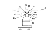
図6は、半自動式の組合せ秤2の概略側面図である。
FIG. 6 is a schematic side view of the
この組合せ秤2は、基本的に従来の半自動式の組合せ秤と同様である。組合せ秤2の各物品投入口25の投入ゲート26の直下には、供給ホッパ40が配設され、各々の供給ホッパ40の下方には、2つの収納室41-1、41-2を有する計量部としての計量ホッパ41が配設されている。
The
各供給ホッパ40は、独立して開閉可能な2つの排出ゲート40a、40bを備え、一方の排出ゲート40aを開放することによって、計量ホッパ41の一方の収納室41-1に物品を排出し、他方の排出ゲート40bを開放することによって、計量ホッパ41の他方の収納室41-2に物品を排出することが可能である。
Each
各計量ホッパ41は、その一方の収納室41-1に排出ゲート41aが設けられると共に、他方の収納室41-2に排出ゲート41bが設けられ、各排出ゲート41a、41bを開放することにより、各収納室41-1,41-2から別々に物品を排出することが可能である。
Each measuring
各計量ホッパ41には、ロードセル等の重量センサ42が取り付けられており、この重量センサ42によって計量ホッパ41内の物品の重量が検出され、その出力が、後述の組合せ秤2の制御部に送られる。これにより組合せ秤2の制御部は、計量ホッパ41内の物品の重量の変化に基づいて、計量ホッパ41の各々の収納室41-1,41-2内の物品の重量を算出し、各計量ホッパ41の各々の収納室41-1,41-2内の物品の重量に基づいて、後述の組合せ演算を行う。
A
計量ホッパ41の下方には、計量ホッパ41から排出された物品を受けて搬送する集合コンベヤ43が配設されている。この集合コンベヤ43によって搬送された物品は、図示しない包装機へ供給される。包装機では、所定重量範囲となる物品を真空包装する。
Below the measuring
組合せ秤2の制御部は、物品を保持している計量ホッパ41の各収納室41-1、41-2内の物品の重量を種々組合せた合計重量である組合せ重量が、所定重量範囲内となる収納室41-1、41-2の組合せを1つ選択する組合せ演算を行い、選択された収納室41-1、41-2の物品を、集合コンベヤ43へ排出する。
The control unit of the
上記のような構成を有する本実施形態の計量システムでは、前段搬送機構3の搬送方向の上手側である始端部に供給された物品wは、物品排出機構4によって搬送方向の3箇所から排出されて夫々の分配搬送機構5に送り込まれる。各分配搬送機構5に送り込まれた物品wは、更に3箇所に分配されて振動フィーダ6に送り込まれ、都合、9台の振動フィーダ6によって分配搬送された物品wが、組合せ秤2の各物品投入口25に供給される。なお、3台の物品排出機構4を通過して前段搬送機構3の終端に至った物品wは、搬出されて回収容器などに回収され、適時、人手によって再び前段搬送機構3の始端部に供給される。
In the weighing system of the present embodiment having the above-described configuration, the article w supplied to the starting end portion on the upper side of the transport direction of the front
上記のような物品の供給においては、各箇所における物品wの有無、及び、組合せ秤2の各物品投入口25、各振動フィーダ6、各分配搬送機構5、物品排出機構4での物品の要求状況に応じて、各物品排出機構4、各分配搬送機構5、及び、各振動フィーダ6が制御されることになる。
In the supply of articles as described above, the presence or absence of articles w at each location, and the requirements of articles in each
図7は、物品wを検知する物品検知センサの設置状態の一例を示す図2に対応する概略平面図である。 FIG. 7 is a schematic plan view corresponding to FIG. 2 showing an example of the installation state of the article detection sensor that detects the article w.
この実施形態の各物品検知センサSa(1)~Sa(3),Sb(1)~Sb(3),Sc(1)~Sc(3),Sd(1)~Sd(3),Se(1)~Se(9),Sf(1)~Sf(9)は、例えば、投光器と受光器を備える透過形の光電センサであり、対向配置された投光器と受光器の間の検知領域を通過する物品wを検知して検知出力を与える。 Each article detection sensor Sa (1) to Sa (3), Sb (1) to Sb (3), Sc (1) to Sc (3), Sd (1) to Sd (3), Se ( 1) to Se (9) and Sf (1) to Sf (9) are, for example, transmissive photoelectric sensors including a floodlight and a light receiver, and pass through a detection region between the floodlights and the light receivers arranged opposite to each other. The article w to be used is detected and a detection output is given.
前段搬送機構3の搬送経路には、各物品排出機構4の直前における検知領域を通過する物品wをそれぞれ検知する第1物品検知センサSa(1)~Sa(3)が配置されている。
The first article detection sensors Sa (1) to Sa (3) for detecting the articles w passing through the detection region immediately before each
また、各物品排出機構4によって排出された物品wが通過する各排出シュート9の基部には、排出された物品を検知する第2物品検知センサSb(1)~Sb(3)がそれぞれ配置されている。なお、各排出シュート9の基部には、各第2物品検知センサSb(1)~Sb(3)の光路を遮らないように透孔が形成されている。
Further, at the base of each
各分配搬送機構5の旋回コンベヤ14の、搬送方向の上手側である始端部及び下手側である終端部には、始端部及び終端部における物品wをそれぞれ検知する第3物品検知センサSc(1)~Sc(3)及び第4物品検知センサSd(1)~Sd(3)がそれぞれ配置されている。なお、旋回コンベヤ14の側板12及び排出カバー13には、第3物品検知センサSc(1)~Sc(3)及び第4物品検知センサSd(1)~Sd(3)の光路を遮らないように透孔が形成されている。
At the start end portion on the upper side and the end portion on the lower side in the transport direction of the
各搬送部としての各振動フィーダ6の各トラフ15の搬送方向の上手側である始端部及び下手側である終端部には、始端部及び終端部における物品wをそれぞれ検知する上手側物品検知センサとしての第5物品検知センサSe(1)~Se(9)、及び、下手側物品検知センサとしての第6物品検知センサSf(1)~Sf(9)が、それぞれ配置されている。なお、振動フィーダ6のトラフ15には、第5物品検知センサSe(1)~Se(9)及び第6物品検知センサSf(1)~Sf(9)の光路を遮らないように、透孔が形成されている。
Good-side article detection sensors that detect articles w at the start and end, respectively, at the start and end on the upper side and the lower end of each
図8は、この実施形態の計量システムの制御構成を示すブロック図である。 FIG. 8 is a block diagram showing a control configuration of the weighing system of this embodiment.
この実施形態の計量システムは、全体を制御する制御装置(制御部)として、プログラマブルコントローラ(以下、「PLC」と略記する)27を備えている。 The weighing system of this embodiment includes a programmable controller (hereinafter, abbreviated as "PLC") 27 as a control device (control unit) that controls the whole.
このPLC27には、操作表示端末であるプログラマブル表示器29が接続されており、このプログラマブル表示器29では、前段搬送機構3や旋回コンベヤ14の搬送速度及び振動フィーダ6の振動強度等の各種の設定操作、及び、後述の警告表示を含む各種の表示が行われる。
A
また、PLC27には、半自動式の組合せ秤2の制御部28から9個の各物品投入口25への物品の排出をそれぞれ要求するときに、ONの排出要求信号(1)~(9)がそれぞれ入力されると共に、上記の各物品検知センサSa(1)~Sa(3),Sb(1)~Sb(3),Sc(1)~Sc(3),Sd(1)~Sd(3),Se(1)~Se(9),Sf(1)~Sf(9)の検知出力が入力される。
Further, the
PLC27は、前段搬送機構3を、前段搬送機構駆動制御回路30を介して制御し、物品排出機構4の各ガイド部材8を、ガイド部材駆動回路31を介して制御する。また、PLC27は、各分配搬送機構5の各旋回コンベヤ14を、旋回コンベヤ駆動制御回路32及び旋回コンベヤ旋回駆動制御回路33を介して制御し、各振動フィーダ6を、振動フィーダ駆動回路34を介して制御する。
The
このPLC27によって、後述のようにして、振動フィーダ6における物品の詰りが生じたか否かが判定され、物品の詰りが生じたと判定されたときには、当該振動フィーダ6へ旋回コンベヤ14から物品が追加投入される。更に、物品の追加投入によっても物品の詰りが解消しなかったと判定したときには、その旨の報知を行う。
As will be described later, the
PLC27による物品供給装置1の制御では、物品供給装置1における物品の搬送方向の最も下手となる振動フィーダ6の制御を行い、次に、その上手となる分配搬送機構5の制御を行い、更に、その上手となる物品排出機構4の制御を行う。
In the control of the
このPLC27は、基本的に、組合せ秤2から各物品投入口25への物品の排出要求があると、排出要求のあった物品投入口25に直ちに物品を排出できるように制御するものであり、各振動フィーダ6のトラフ15の終端部へ物品を搬送して待機できるように制御する。
The
すなわち、振動フィーダ6では、トラフ15の終端部に物品がないときには、トラフ15の始端部で検知された物品を、トラフ15の終端部まで搬送し、トラフ15の始端部で検知された物品がないときには、分配搬送機構5の旋回コンベヤ14に対して物品の投入を要求する。
That is, in the
分配搬送機構5の旋回コンベヤ14では、物品の投入要求のあった振動フィーダ6のトラフ15へ物品を直ちに投入できるように、旋回コンベヤ14の終端部に物品を搬送すると共に、回動位置が制御される。旋回コンベヤ14の終端部に物品がないときには、旋回コンベヤ14の始端部で検知された物品を終端部へ搬送し、旋回コンベヤ14の始端部で物品が検知されないときには、物品排出機構4に対して物品の投入を要求する。
In the
物品の投入要求があった物品排出機構4では、物品排出機構4の直前の検知領域を通過する物品が検知されると、ガイド部材8を駆動して搬送経路に進出する排出姿勢とし、搬送される物品を、搬送経路外の分配搬送機構5の旋回コンベヤ14へ供給する。
When an article passing through the detection area immediately before the
具体的には、前段搬送機構3の搬送経路の各物品排出機構4の直前における検知領域を通過する物品wをそれぞれ検知する第1物品検知センサSa(1)~Sa(3)の検知出力に基づいて、PLC27は、物品排出機構4を排出状態に切換え制御することで、搬送経路の複数個所での物品の排出を開始させることができる。また、各物品排出機構4によって排出された物品wを検知する第2物品検知センサSb(1)~Sb(3)の検知出力に基づいて、PLC27は、物品が排出された後には、物品排出機構4を、物品の通過を許容する許容状態に切換え制御することで、搬送経路の複数個所での物品の排出を終了させることができる。
Specifically, it is used for the detection output of the first article detection sensors Sa (1) to Sa (3) that detect the articles w passing through the detection area immediately before each
第2物品検知センサSb(1)~Sb(3)が排出される物品を検知している期間は、検知出力を継続して与える。PLC27は、第2物品検知センサSb(1)~Sb(3)の検知出力の継続時間に基づいて、物品排出機構4の排出状態の継続時間、すなわち、物品排出機構4によって物品を分配搬送機構5へ排出する時間を制御する。
During the period in which the second article detection sensors Sb (1) to Sb (3) are detecting the ejected article, the detection output is continuously given. Based on the duration of the detection output of the second article detection sensors Sb (1) to Sb (3), the
上記のように、物品の投入要求があった物品排出機構4では、ガイド部材8を駆動して搬送経路に進出する排出姿勢とし、搬送される物品を、搬送経路外の分配搬送機構5の旋回コンベヤ14へ供給するので、前段搬送機構3の搬送ベルト7の始端側から供給される物品wは、物品排出機構4によって、旋回コンベヤ14からの物品の投入要求に応じて、3台の旋回コンベヤ14のいずれかに供給される。
As described above, in the
組合せ秤2へ物品を供給する振動フィーダ6は、トラフ15を振動駆動することで旋回コンベヤ14から落下投入される物品を振動搬送するが、物品の性状等によっては、トラフ15の物品の搬送方向の上手側で物品が詰って下手側へ搬送できない場合がある。
The
物品が振動フィーダ6のトラフ15の上手側、例えば、物品が投入されるトラフ15の始端部で詰ると、その詰りが生じた振動フィーダ6に対応する第5物品検知センサSeによって物品が検知された状態のままとなる。このように振動フィーダ6のトラフ15の始端部の物品を検知する第5物品検知センサSeが、物品を検知した状態のままであるので、旋回コンベヤ14から当該振動フィーダ6へ新たな物品が投入されることはなく、物品が詰ったままの状態が継続することになる。
When an article is clogged on the upper side of the
物品が詰ったままの状態の振動フィーダ6からは、組合せ秤2へ物品を供給することができず、このため、組合せ秤2における組合せ精度が低下したり、あるいは、組合せ演算が成立せず、その分、生産数が減ってしまうことになる。
The article cannot be supplied to the
この実施形態では、振動フィーダ6のトラフ5の始端部で物品の詰りが生じたか否かを判定し、詰りが生じたと判定したときには、旋回コンベヤ14から物品を、当該振動フィーダ6へ追加投入するようにしている。
In this embodiment, it is determined whether or not the article is clogged at the start end of the
このように物品を追加投入することによって、振動フィーダ6のトラフ5の始端部で詰っている物品は、追加投入される物品によって、搬送方向の下手側へ押し出されるようにして、追加投された物品と共に、下手側へ振動搬送され、物品の詰りが解消される。
By additionally loading the article in this way, the article clogged at the start end of the
図9~図11は、物品の詰りが追加投入によって解消される状況を示す概略斜視図であり、詰りが生じた一つの振動フィーダ6を示している。
9 to 11 are schematic perspective views showing a situation in which the clogging of the article is cleared by the additional loading, and shows one
図9に示されるように、振動フィーダ6のトラフ15の始端部において、物品w1が詰ると、図10に示すように、旋回コンベヤ14から物品w2が追加投入される。これによって、詰っていた物品w1は、追加投入された物品w2によって下手側へ押し出されて搬送し始め、図11に示すように、追加投入された物品w2と共に、下手側へ搬送されて詰りが解消される。
As shown in FIG. 9, when the article w1 is clogged at the start end of the
この実施形態では、振動フィーダ6のトラフ5の始端部において、物品の詰りが生じたか否かを、次のようにして判定している。
In this embodiment, it is determined as follows whether or not the article is clogged at the starting end of the
すなわち、第5物品検知センサSeによって、振動フィーダ6のトラフ15の始端部に物品が在ることが検知されている状態であって、かつ、第6物品検知センサSfによって、振動フィーダ6のトラフ15の終端部の物品が検知されていない状態、つまり、振動フィーダ6のトラフ15の始端部に物品が在るが、終端部に物品が存在しない状態が、予め定めた時間以上継続したときに、振動フィーダ6のトラフ15の始端部で物品の詰りが生じたと判定するものである。
That is, it is in a state where the presence of an article is detected at the start end of the
予め定めた時間は、振動フィーダ6のトラフ15の始端部の物品が、トラフ15の終端部まで搬送されるのに要する時間以上であるのが好ましい。この予め定めた時間は、操作表示端末である上記のプログラマブル表示器29を操作して設定することができる。
The predetermined time is preferably longer than the time required for the article at the start end of the
上記のように、振動フィーダ6の終端部に物品が存在しないとき、すなわち、第6物品検知センサSfで物品が検知されていないときには、振動フィーダ6は、上手側の物品が終端部へ搬送されるように振動している。したがって、振動フィーダ6のトラフ15の始端部に物品があれば、その物品が振動フィーダ6のトラフ15の終端部まで搬送されて、第6物品検知センサSfによって検知されるはずである。
As described above, when there is no article at the end of the
しかし、振動フィーダ6のトラフ15の始端部で、物品の詰りが生じているときには、予め定めた時間が経過しても、振動フィーダ6のトラフ15の始端部の物品は、下手側へ搬送されないために、第6物品検知センサSfでは、物品を検知することができない。
However, when the article is clogged at the start end of the
したがって、この実施形態では、第5物品検知センサSeによって、振動フィーダ6のトラフ15の始端部に物品が在ることが検知されている状態であって、かつ、第6物品検知センサSfによって、振動フィーダ6のトラフ15の終端部の物品が検知されていない状態が、予め定めた時間以上継続したときには、振動フィーダ6のトラフ15の始端部で物品の詰りが生じたと判定する。物品の詰りが生じたと判定したときには、上記にように、旋回コンベヤ14から、当該振動フィーダ6へ物品を追加投入し、物品の詰りを解消するのである。この追加投入は、旋回コンベヤ14から振動フィーダ6への物品の通常の投入と同様に行われる。なお、追加投入を、通常の投入と異ならせてもよく、例えば、追加投入では、投入する物品の量を、通常の投入に比べて多くしてもよい。
Therefore, in this embodiment, the presence of an article is detected by the fifth article detection sensor Se at the start end of the
更に、この実施形態では、旋回コンベヤ14からの物品の追加投入によっても、物品の詰りが解消しない場合には、報知部としてプログラマブル表示器29に、詰りが生じている振動フィーダ6を特定すると共に、その詰りが生じている箇所(始端部)を示す警告表示を行って報知する。更に、図示しないブザによる警告音で報知すると共に、図示しない警告灯を点灯させて報知する。
Further, in this embodiment, if the clogging of the article is not cleared even by the additional loading of the article from the
これによって、作業者は、詰っている物品を、振動フィーダ6の下手側へ移動させたり、取り除くなどして、物品の詰りを解消する。
As a result, the operator moves or removes the clogged article to the lower side of the
追加投入によって物品の詰りが解消したか否かの判定は、振動フィーダ6の始端部の物品を依然として検知したままの状態が、追加投入から設定時間以上継続したときに、解消されていないと判定することができる。
The determination as to whether or not the clogging of the article has been cleared by the additional loading is determined not to be cleared when the state in which the article at the start end of the
あるいは、第5物品検知センサSeによって、振動フィーダ6のトラフ15の始端部に物品が在ることが検知されている状態であって、かつ、第6物品検知センサSfによって、振動フィーダ6のトラフ15の終端部の物品が検知されていない状態が、予め定めた時間以上継続したときには、詰りが生じているとして、追加投入が行われるので、振動フィーダ6の始端部の物品を依然として検知したままの状態が、前記予め定めた時間以上継続したときから設定時間以上継続したときに、解消されていないと判定することができる。
Alternatively, it is in a state where the presence of an article is detected at the start end of the
この実施形態では、上手側物品検知センサとしての第5物品検知センサSe(1)~Se(9)は、物品が投入される振動フィーダ6の搬送方向の始端部における物品を検知するので、始端部の物品が搬送方向の下手側に搬送されて第5物品検知センサSe(1)~Se(9)によって物品が検知されなくなると、旋回コンベヤ14から新たな物品を、振動フィーダ6の始端部へ直ちに投入することができる。また、下手側物品検知センサとしての第6物品検知センサSf(1)~Sf(9)は、振動フィーダ6の物品を排出する搬送方向の終端部における物品を検知するので、終端部の物品が組合せ秤2に排出されて第6物品検知センサSf(1)~Sf(9)によって物品が検知されなくなると、振動フィーダ6の上手側の物品を、終端部まで直ちに搬送することができる。
In this embodiment, the fifth article detection sensors Se (1) to Se (9) as the upper article detection sensor detect the article at the start end portion of the
次に、物品の詰りを解消する本実施形態の振動フィーダ6の制御の一例を、図12及び図13のフローチャートに基づいて説明する。この図12及び図13に示される制御処理は、9台の各振動フィーダ6について順次行われる。
Next, an example of the control of the
図12に示すように、先ず、運転スイッチがONされると(ステップS1)、振動フィーダ6のトラフ15の下手側の終端部の物品を検知する第6物品検知センサSfがONしているか否か、すなわち、物品を検知したか否かを判断し(ステップS2)、物品を検知したときには、振動フィーダ6の終端部に物品が到達したとして、振動フィーダ6の駆動を停止する(ステップS3)。
As shown in FIG. 12, first, when the operation switch is turned on (step S1), whether or not the sixth article detection sensor Sf for detecting the article at the lower end of the
次に、組合せ秤2から振動フィーダ6へ物品の排出を要求する排出要求信号がONしたか否かを判断し(ステップS4)、排出要求信号がONしたときには、振動フィーダ6の終端部の物品を排出して組合せ秤2へ物品を供給するために、振動フィーダ6を駆動する(ステップS5)。
Next, it is determined whether or not the discharge request signal requesting the discharge of the article from the
この振動フィーダ6の駆動と共に、その駆動時間を計測する駆動時間計測用タイマTaによる計測を開始し(ステップS6)、計測時間が、第1所定時間T1以上となったか否かを判断する(ステップS7)。この第1所定時間T1は、振動フィーダ6の終端部に存在する物品を、振動フィーダ6から排出して組合せ秤2へ供給できる駆動時間以上に設定されるのが好ましい。
Along with driving the
ステップS7で、駆動時間計測用タイマTaによる計測時間が、第1所定時間T1以上になったときには、振動フィーダ6の終端部の物品が排出されて組合せ秤2に供給されたとして、振動フィーダ6の駆動を停止し(ステップS8)、駆動時間計測用タイマTaを、初期値=0にリセットする(ステップS9)。
In step S7, when the measurement time by the drive time measurement timer Ta becomes T1 or more for the first predetermined time, it is assumed that the article at the end of the
本発明の他の実施形態として、振動フィーダ6を第1所定時間以上駆動するのに代えて、第6物品検知センサSfでトラフ15の終端部の物品が検知されなくなった時点で、物品が組合せ秤2へ供給されたとして、振動フィーダ6の駆動を停止するようにしてもよい。
As another embodiment of the present invention, instead of driving the
次に、組合せ秤2から振動フィーダ6へ物品の排出を要求する排出要求信号がOFFしたか否かを判断する(ステップS10)。このステップS10で、組合せ秤2から振動フィーダ6へ物品の排出を要求する排出要求信号がOFFしたときには、振動フィーダ6の終端部の物品が排出されて組合せ秤2へ供給されたとして、ステップS11を経て、ステップS1に戻る。
Next, it is determined whether or not the discharge request signal requesting the discharge of the article from the
この実施形態では、振動フィーダ6のトラフ15の終端部における物品の詰りが生じたときにも、それを報知するようにしている。このため、上記ステップS11では、終端部における物品の詰りは生じていないとして、振動フィーダ6の終端部での物品の詰りが生じたか否かを判定するための判定時間を計測するための判定時間計測用タイマTbを、初期値=0にリセットする。
In this embodiment, even when an article is clogged at the end of the
上記ステップS10において、組合せ秤2からの排出要求信号がOFFしていないとき、すなわち、依然として組合せ秤2からの排出要求信号がONしているときには、振動フィーダ6の終端部の物品を排出して組合せ秤2へ供給できる第1所定時間T1以上に亘って振動フィーダ6を駆動したにも拘わらず、組合せ秤2に未だ物品が供給されていないとして、上記判定時間計測用タイマTbが初期値(=0)ままであるか否かを判断する(ステップS12)。
In step S10, when the discharge request signal from the
判定時間計測用タイマTbが、初期値のままであるときには、判定時間計測用タイマTbによる計測を開始してステップS14に移り(ステップS13)、初期値のままでないときには、既に判定時間を計測中であるとして、ステップS14に移る。 When the determination time measurement timer Tb remains at the initial value, the measurement by the determination time measurement timer Tb is started and the process proceeds to step S14 (step S13). When the determination time measurement timer Tb does not remain at the initial value, the determination time is already being measured. Assuming that, the process proceeds to step S14.
ステップS14では、判定時間計測用タイマTbによる計測時間が、第2所定時間T2以上となったか否かを判断する。この第2所定時間T2は、振動フィーダ6の終端部の物品を排出して組合せ秤2へ供給するために、振動フィーダ6を駆動し、この駆動を停止してから、物品が供給された組合せ秤2からの排出要求信号がOFFされるまでに要する時間以上であるのが好ましい。
In step S14, it is determined whether or not the measurement time by the determination time measurement timer Tb is equal to or longer than the second predetermined time T2. The second predetermined time T2 drives the
このステップS14で、判定時間計測用タイマTbによる計測時間が、第2所定時間T2以上となったときには、振動フィーダ6を、その終端部に在る物品を排出して組合せ秤2へ供給できる第1所定時間T1以上に亘って駆動したにも拘わらず、組合せ秤2からの排出要求信号がONのままの状態が、第2所定時間T2以上に亘って継続したことになる。このときには、振動フィーダ6の終端部で物品の詰りが生じたとして、振動フィーダ6のトラフ15の終端部で詰りが生じた旨の報知を行ってステップS1に戻る(ステップS15)。このステップS15の詰りの報知は、プログラマブル表示器29に、物品の詰りが生じている振動フィーダ6及びその詰りの箇所を警告表示することによって行われる。更に、この報知は、図示しないブザによる警告音、及び、図示しない警告灯の点灯によって行われる。
In step S14, when the measurement time by the determination time measurement timer Tb becomes the second predetermined time T2 or more, the
これによって、作業者は、振動フィーダ6のトラフ15の終端部で詰っている物品を、組合せ秤2の物品投入口25に投入するなどして、物品の詰りを解消する。
As a result, the operator clears the clogging of the article by charging the article clogged at the end of the
上記ステップS2において、振動フィーダ6のトラフ15の終端部の物品を検知する第6物品検知センサSfがONしていないときには、物品を振動フィーダ6の終端部へ搬送するために、図13のステップS16に示すように、振動フィーダ6を駆動し、上記駆動時間計測用タイマTa及び上記判定時間計測用タイマTbを、初期値=0にリセットする(ステップS17)。
In step S2, when the sixth article detection sensor Sf for detecting the article at the end of the
次に、振動フィーダ6のトラフ15の始端部の物品を検知する第5物品検知センサSeがONしているか否かを判断し(ステップS18)、第5物品検知センサSeがONしているときには、振動フィーダ6のトラフ15の終端部の物品を検知する第6物品検知センサSfがONしているか否かを判断し(ステップS19)、第6物品検知センサSfがONしているときには、ステップS1に戻る。
Next, it is determined whether or not the fifth article detection sensor Se that detects the article at the start of the
ステップS18において、第5物品検知センサSeがONしており、ステップS19において、第6物品検知センサSfがONしていないとき、すなわち、振動フィーダ6のトラフ15の始端部に物品が存在し、かつ、振動フィーダ6のトラフ15の終端部に物品が存在しないときには、その状態の継続時間を計測する継続時間計測用タイマTcが初期値=0であるか否かを判断し(ステップS20)、初期値であるときには、継続時間計測用タイマTcによる計測を開始してステップS22に移り(ステップS21)、初期値でないときには、既に計測を開始しているとして、ステップS22に移る。
In step S18, when the fifth article detection sensor Se is ON and in step S19, the sixth article detection sensor Sf is not ON, that is, the article is present at the start end of the
ステップS22では、継続時間計測用タイマTcによる計測時間が、振動フィーダ6のトラフ15の始端部での物品の詰りが生じたと判定するための予め定めた時間としての第3所定時間T3以上になったか否かを判断し、第3所定時間T3以上になっていないときには、ステップS1に戻る。
In step S22, the measurement time by the duration measurement timer Tc becomes the third predetermined time T3 or more as a predetermined time for determining that the article is clogged at the start end of the
ステップS22で、継続時間計測用タイマTcによる計測時間が、第3所定時間T3以上になったときには、振動フィーダ6のトラフ15の始端部で物品の詰りが生じたと判定する。このときには、その詰りを解消するための追加投入によって詰りが解消した否かを判定するための判定時間を計測する判定時間計測用タイマTdが初期値=0であるか否かを判断する(ステップS23)。ステップS23で、判定時間計測用タイマTdが、初期値であるときには、追加投入前であるとして、当該振動フィーダ6へ物品の追加投入を要求する物品投入命令フラグをONして、ステップS25に移り(ステップS24)、初期値でないときには、既に追加投入がされているとして、ステップS25に移る。
In step S22, when the measurement time by the duration measurement timer Tc becomes T3 or more for the third predetermined time, it is determined that the article is clogged at the start end of the
ステップS24で物品投入命令フラグがONされることで、旋回コンベヤ14から当該振動フィーダ6のトラフ15の始端部に物品が追加投入され、物品投入命令フラグはOFFされる。
When the article loading command flag is turned on in step S24, the article is additionally loaded from the
ステップS25では、振動フィーダ6のトラフ15の始端部の物品を検知する第5物品検知センサSeがOFFしたか否かを判断し、OFFしたときには、物品の追加投入によって、トラフ15の始端部で詰っていた物品が、追加投入された物品に押し出されるようにして、それら物品が下手側へ振動搬送されて、トラフ15の始端部の物品が存在しなくなった、すなわち、物品の詰りが解消したとして、上記継続時間計測用タイマTc及び上記判定時間計測用タイマTdを、初期値=0にリセットしてステップS1に戻る(ステップS26)。
In step S25, it is determined whether or not the fifth article detection sensor Se, which detects the article at the start end of the
ステップS25で、振動フィーダ6のトラフ15の始端部の物品を検知する第5物品検知センサSeがOFFしていないとき、すなわち、第5物品検知センサSeが、振動フィーダ6の始端部の物品を依然として検知したままの状態であるときには、追加投入によって詰りが解消した否かを判定するための判定時間を計測する判定時間計測用タイマTdが初期値であるか否かを判断し(ステップS27)、初期値であるときには、判定時間計測用タイマTdによる計測を開始してステップS29に移り(ステップS28)、初期値でないときには、既に判定時間計測用タイマTdによる計測が開始されているとして、ステップS29に移る。
In step S25, when the fifth article detection sensor Se that detects the article at the beginning of the
ステップS29では、判定時間計測用タイマTdによる計測時間が、追加投入によって物品の詰りが解消していないと判定するための第4所定時間T4以上となったか否かを判断する。この第4所定時間T4は、詰りが生じた振動フィーダ6への物品の追加投入を要求してから、物品の追加投入によって、振動フィーダ6の始端部の詰りが解消されて追加投入された物品が、下手側に搬送されて第5物品検知センサSeによって物品が検知されなくなるまでに要する時間以上であるのが好ましい。
In step S29, it is determined whether or not the measurement time by the determination time measurement timer Td is equal to or longer than the fourth predetermined time T4 for determining that the clogging of the article has not been cleared by the additional loading. The fourth predetermined time T4 requests the additional loading of the article into the clogged
ステップS29で、判定時間計測用タイマTdによる計測時間が、第4所定時間T4以上になっていないときには、ステップS25に戻り、第4所定時間T4以上になったときには、第5物品検知センサSeによって、追加投入後も振動フィーダ6の始端部の物品を依然として検知したままの状態であり、追加投入によって物品の詰りが解消していないとして物品の詰りを報知してステップS1に戻る(ステップS30)。このステップS30の詰りの報知は、プログラマブル表示器29に、物品の詰りが生じている振動フィーダ6及びその詰りの箇所を警告表示することによって行われる。更に、この報知は、図示しないブザによる警告音、及び、図示しない警告灯の点灯によって行われる。
In step S29, when the measurement time by the determination time measurement timer Td is not equal to or longer than the fourth predetermined time T4, the process returns to step S25, and when the measurement time is longer than the fourth predetermined time T4, the fifth article detection sensor Se is used. Even after the additional loading, the article at the starting end of the
上記ステップS18において、振動フィーダ6のトラフ15の始端部の物品を検知する第5物品検知センサSeがONしていないときには、当該振動フィーダ6へ物品の通常の投入を要求する物品投入命令フラグをONし(ステップS31)、上記継続時間計測用タイマTc及び上記判定時間計測用タイマTdを初期値にリセットしてステップS1に戻る(ステップS32)。
In step S18, when the fifth article detection sensor Se that detects the article at the start of the
ステップS31で物品投入命令フラグがONされることで、旋回コンベヤ14から当該振動フィーダ6のトラフ15の始端部へ通常の物品の投入が行われ、物品投入命令フラグはOFFされる。
When the article loading command flag is turned on in step S31, a normal article is loaded from the
図12の上記ステップS1において、運転スイッチがOFFされると、図13に示されるように、振動フィーダ6の駆動を停止し(ステップS33)、上記振動時間計測用タイマTa、上記判定時間計測用タイマTb、上記継続時間計測用タイマTc及び上記判定時間計測用タイマTdを初期値にリセットして終了する(ステップS34)。なお、上記第1~第4所定時間T1~T4は、操作表示端末である上記のプログラマブル表示器29を操作して設定することができる。
In step S1 of FIG. 12, when the operation switch is turned off, the drive of the
上記のように本実施形態によれば、振動フィーダ6のトラフ15の始端部で物品の詰りが生じると、旋回コンベヤ14から振動フィーダ6へ物品が追加投入されて詰った物品が押し出されるようにして下手側へ搬送されて物品の詰りが解消される。
As described above, according to the present embodiment, when the article is clogged at the start end of the
これによって、物品が詰ったままの状態が継続されて、当該振動フィーダ6から組合せ秤2へ物品を供給することができず、組合せ秤2における組合せ精度が低下したり、あるいは、組合せ演算が成立せず、その分、生産数が減ってしまうのを防止することができる。
As a result, the state in which the article is still packed continues, the article cannot be supplied from the
また、物品の追加投入によって、物品の詰りが解消されない場合には、それが報知されるので、作業者は、詰っている物品を下手側へ移動させたり、取り除くなどして、物品の詰りを解消することができる。 In addition, if the clogging of the article is not cleared by the additional loading of the article, the jamming of the article is notified, so that the worker moves or removes the jammed article to the lower side to clear the clogging of the article. It can be resolved.
更に、本実施形態では、振動フィーダ6のトラフ15の終端部で物品の詰りが生じた場合にも、それが報知されるので、作業者は、詰っている物品を、組合せ秤2の物品投入口25へ投入するなどして、物品の詰りを解消することができる。
Further, in the present embodiment, even if the article is clogged at the end of the
なお、振動フィーダ6のトラフ15の始端部に投入された物品が、下手側へ搬送されて、始端部と終端部との間の中間領域で詰ったように場合には、振動フィーダ6のトラフ15の始端部の物品を検知する第5物品検知センサSeがOFFするので、上記図13のステップS31に示すように、振動フィーダ6への物品投入フラグがONして、旋回コンベヤ14から通常の物品の投入が行われる。これによって、投入された物品が、下手側へ搬送されて、詰っている物品を下手側へ押すように搬送して、物品の詰りを解消することができる。
If the article thrown into the start end of the
また、本実施形態によれば、前段搬送機構3の搬送方向の上手側において物品を供給すると、その搬送径路の3箇所において、物品排出機構4のガイド部材8によって搬送経路外の3台の各分配搬送機構5の各旋回コンベヤ14へ排出される。排出された物品は、各旋回コンベヤ14によって、3台の各振動フィーダ6の各トラフ15にそれぞれ振分け搬送される。すなわち、前段搬送機構3の搬送方向の上手側1箇所に供給した物品を、9台の振動フィーダ6の各トラフ15に振分け搬送し、各振動フィーダ6の各トラフ15によって、組合せ秤2の9個の物品投入口25へ供給することができる。
Further, according to the present embodiment, when the article is supplied on the upper side in the transport direction of the front-
したがって、粘着性を有するブロイラーの肉片である物品wを、組合せ秤2の9個の物品投入口25へ自動で供給することができ、従来のように、作業者が、物品を一々掴んで半自動式の組合せ秤の物品投入口へ投入する作業を行う必要がなく、大幅に作業者の労力を軽減することができる。
Therefore, the article w, which is a piece of meat of the broiler having adhesiveness, can be automatically supplied to the nine
[その他の実施形態]
本発明は、以下のような形態で実施することもできる。[Other embodiments]
The present invention can also be carried out in the following forms.
(1)物品検知センサとしては、上記のような透過形の光電センサに限らず、反射形の光電センサ、超音波センサ、等の他のセンサを利用することもできる。 (1) The article detection sensor is not limited to the transmissive photoelectric sensor as described above, but other sensors such as a reflective photoelectric sensor and an ultrasonic sensor can also be used.
(2)振動フィーダへの物品の投入は、旋回コンベヤに限らず、他のコンベヤであってもよく、また、コンベヤに代えて振動搬送する形態とすることもできる。 (2) The loading of the article into the vibration feeder is not limited to the swirling conveyor, but may be another conveyor, or may be in the form of vibrating and transporting instead of the conveyor.
(3)前段搬送機構は、物品wの大きさ、重量、性状、等に応じて任意に選択することができ、例えば、硬質樹脂材あるいは金属材からなる多数の横向きスラットバーを繋いで環状ベルトにしたスラット型コンベヤ、金網ベルトコンベヤ、等を利用することもできる。 (3) The front-stage conveyor mechanism can be arbitrarily selected according to the size, weight, properties, etc. of the article w. For example, an annular belt connecting a large number of lateral slat bars made of a hard resin material or a metal material. It is also possible to use a slatted conveyor, a wire mesh belt conveyor, or the like.
(4)物品排出機構を、搬送径路脇に、搬送方向と直交する方向に出退可能なプッシャーを配設し、プッシャーを搬送経路内へ進出させて物品を搬送経路の外側方に押出す形態とすることもできる。 (4) An article discharge mechanism is provided on the side of the transport path with a pusher capable of moving in and out in a direction orthogonal to the transport direction, and the pusher is advanced into the transport path to push the article outward from the transport path. It can also be.
(5)物品の供給先は、組合せ秤に限らないのは勿論であり、供給先の数も9箇所に限らず、任意である。 (5) The supply destination of the article is not limited to the combination scale, and the number of supply destinations is not limited to nine and is arbitrary.
(6)上記実施形態では、物品として、解体されたブロイラーの肉片に適用して説明したが、かかる肉片に限らず、例えば、イカやカツオ等の魚介類、その他の物品に適用してもよい。 (6) In the above embodiment, the description has been made by applying it to a disassembled broiler meat piece as an article, but the present invention is not limited to such a meat piece, and may be applied to, for example, fish and shellfish such as squid and bonito, and other articles. ..
1 物品供給装置
2 組合せ秤
3 前段搬送機構
4 物品排出機構
5 分配搬送機構
6 振動フィーダ(搬送部)
8 ガイド部材
14 旋回コンベヤ(投入コンベヤ)
15 トラフ
27 PLC(制御部)
w 物品
Se 第5物品検知センサ(上手側物品検知センサ)
Sf 第6物品検知センサ(下手側物品検知センサ)1
8
15
w Article Se 5th article detection sensor (good side article detection sensor)
Sf 6th article detection sensor (lower side article detection sensor)
Claims (9)
前記搬送部の前記物品の搬送方向の上手側における前記物品を検知する上手側物品検知センサと、
前記搬送部の前記物品の搬送方向の下手側における前記物品を検知する下手側物品検知センサと、
前記上手側物品検知センサ及び前記下手側物品検知センサの検知出力に基づいて、前記搬送部への物品の投入を制御する制御部とを備え、
前記制御部は、前記上手側物品検知センサによって物品が検知され、かつ、前記下手側物品検知センサによって物品が検知されない状態が、予め定めた時間以上継続したときに、前記搬送部へ物品を追加投入する、
物品供給装置。An article supply device provided with a transport unit for transporting the loaded articles to a supply destination.
A good-side article detection sensor that detects the article on the upper side in the transport direction of the article in the transport unit, and
A lower-side article detection sensor that detects the article on the lower side of the transport section in the transport direction of the article, and a lower-side article detection sensor.
A control unit for controlling the loading of articles into the transport unit based on the detection output of the upper article detection sensor and the lower article detection sensor is provided.
The control unit adds an article to the transport unit when the article is detected by the upper article detection sensor and the article is not detected by the lower article detection sensor for a predetermined time or longer. throw into,
Goods supply equipment.
前記制御部は、前記振動フィーダの駆動を制御するものであって、前記下手側物品検知センサによって、前記物品が検知されるまで、前記振動フィーダを駆動する、
請求項1に記載の物品供給装置。The transport unit is a vibration feeder that vibrates and transports the article to be charged.
The control unit controls the driving of the vibration feeder, and drives the vibration feeder until the article is detected by the lower side article detection sensor.
The article supply device according to claim 1.
請求項2に記載の物品供給装置。The control unit drives the vibration feeder when the article is detected by the lower side article detection sensor and the drive of the vibration feeder is stopped, and when the supply destination requests to discharge the article. To discharge the article to the supply destination,
The article supply device according to claim 2.
請求項1ないし3のいずれか一項に記載の物品供給装置。The control unit loads the article into the transport unit when the article is not detected by the upper article detection sensor.
The article supply device according to any one of claims 1 to 3.
前記制御部は、前記上手側物品検知センサによって物品が検知されている状態が、前記追加投入の前から前記追加投入の後に亘って継続すると共に、前記予め定めた時間以上継続したときからの継続時間、又は、前記追加投入からの継続時間が、設定時間以上になったときには、前記報知部によって物品の詰りを報知する、
請求項1ないし4のいずれか一項に記載の物品供給装置。It is controlled by the control unit and includes a notification unit for notifying the clogging of the article in the transport unit.
The control unit continues the state in which the article is detected by the upper article detection sensor from before the additional loading to after the additional loading and from the time when the state is continued for a predetermined time or longer. When the time or the duration from the additional charging exceeds the set time, the notification unit notifies the jam of the article.
The article supply device according to any one of claims 1 to 4.
前記制御部は、前記投入コンベヤの駆動を制御する、
請求項1に記載の物品供給装置。A loading conveyor for transporting the article and charging the article into the transport section is provided.
The control unit controls the drive of the input conveyor.
The article supply device according to claim 1.
前記投入コンベヤは、前記物品の搬送方向の始端部を中心に回動して前記搬送方向の終端部から、前記複数の振動フィーダに物品をそれぞれ投入する旋回コンベヤである、
請求項6に記載の物品供給装置。The plurality of transport units are provided, and the plurality of transport units are a plurality of vibration feeders that vibrate and transport the articles to be loaded.
The loading conveyor is a swivel conveyor that rotates around a start end portion in the transport direction of the article and feeds the article into the plurality of vibration feeders from the end portion in the transport direction.
The article supply device according to claim 6.
請求項7に記載の物品供給装置。Each of the plurality of vibration feeders conveys the article to a plurality of article input ports of the combination scale to which the supply destination is located.
The article supply device according to claim 7.
前記前段搬送機構による前記物品の搬送経路の複数個所において、搬送されてきた物品の通過を許容する許容状態と、搬送されてきた物品を前記搬送径路外に排出する排出状態とに切換え可能な物品排出機構とを備え、
前記物品排出機構で前記搬送経路外へ排出された物品が、前記投入コンベヤに供給される、
請求項6ないし8のいずれか一項に記載の物品供給装置。A pre-stage transport mechanism that transports the supplied goods,
An article that can be switched between a permissible state that allows the transported article to pass through at a plurality of locations of the article transport path by the pre-stage transport mechanism and a discharge state that discharges the transported article out of the transport path. Equipped with a discharge mechanism,
The article discharged out of the transport path by the article discharge mechanism is supplied to the loading conveyor.
The article supply device according to any one of claims 6 to 8.
Applications Claiming Priority (1)
| Application Number | Priority Date | Filing Date | Title |
|---|---|---|---|
| PCT/JP2018/022465 WO2019239498A1 (en) | 2018-06-12 | 2018-06-12 | Article supply device |
Publications (2)
| Publication Number | Publication Date |
|---|---|
| JPWO2019239498A1 JPWO2019239498A1 (en) | 2021-06-24 |
| JP7023591B2 true JP7023591B2 (en) | 2022-02-22 |
Family
ID=68842037
Family Applications (1)
| Application Number | Title | Priority Date | Filing Date |
|---|---|---|---|
| JP2020524992A Active JP7023591B2 (en) | 2018-06-12 | 2018-06-12 | Goods supply equipment |
Country Status (2)
| Country | Link |
|---|---|
| JP (1) | JP7023591B2 (en) |
| WO (1) | WO2019239498A1 (en) |
Families Citing this family (2)
| Publication number | Priority date | Publication date | Assignee | Title |
|---|---|---|---|---|
| JP7130335B2 (en) * | 2018-12-14 | 2022-09-05 | 大和製衡株式会社 | Combination weighing device |
| JP2022140126A (en) * | 2021-03-12 | 2022-09-26 | 株式会社イシダ | Article transport device and combination weighing device |
Family Cites Families (4)
| Publication number | Priority date | Publication date | Assignee | Title |
|---|---|---|---|---|
| JPH02110013A (en) * | 1988-10-18 | 1990-04-23 | Sumitomo Heavy Ind Ltd | Method and device for detecting clogging of carried article in hood of carrying equipment |
| JP2509632Y2 (en) * | 1989-12-20 | 1996-09-04 | 株式会社アドバンテスト | IC test carrier |
| ES2470967T3 (en) * | 2011-09-26 | 2014-06-24 | Carefusion Germany 326 Gmbh | Device and procedure for individualization of loose items to be stored in an automated warehouse |
| JP6827754B2 (en) * | 2016-09-30 | 2021-02-10 | 井関農機株式会社 | Crop aligner |
-
2018
- 2018-06-12 WO PCT/JP2018/022465 patent/WO2019239498A1/en active Application Filing
- 2018-06-12 JP JP2020524992A patent/JP7023591B2/en active Active
Also Published As
| Publication number | Publication date |
|---|---|
| JPWO2019239498A1 (en) | 2021-06-24 |
| WO2019239498A1 (en) | 2019-12-19 |
Similar Documents
| Publication | Publication Date | Title |
|---|---|---|
| WO2018139127A1 (en) | Vibrating feeder and item supply device using same | |
| CN110191851B (en) | Article supply device and weighing system provided with same | |
| JP7130335B2 (en) | Combination weighing device | |
| JP6723655B2 (en) | Weighing device | |
| JP7023591B2 (en) | Goods supply equipment | |
| JP6858628B2 (en) | Article sorting device and article supply device equipped with it | |
| JP6866218B2 (en) | Goods supply device and weighing system equipped with it | |
| JP7009070B2 (en) | Goods regulation device and goods supply device equipped with it | |
| JP7220952B2 (en) | Combination weighing device | |
| JPH0360049B2 (en) | ||
| WO2003062764A1 (en) | Combined weighing equipment | |
| JPH09278168A (en) | Separately feeding method for accumulated bar like articles | |
| JP6925735B2 (en) | Goods supply device | |
| JP7220949B2 (en) | Article supply device | |
| JP7366498B2 (en) | Goods supply device and weighing system equipped with it | |
| JP6935133B2 (en) | Article guidance device and article supply device | |
| JPH06144543A (en) | Conveying device | |
| JP5669096B2 (en) | Combination scale | |
| JP2021080050A (en) | Article feeder and measuring system comprising the same | |
| JP5669097B2 (en) | Combination scale | |
| JP2010175408A (en) | Combination weighing device | |
| JPH0485208A (en) | Commodity feeder for bucket conveyor |
Legal Events
| Date | Code | Title | Description |
|---|---|---|---|
| A621 | Written request for application examination |
Free format text: JAPANESE INTERMEDIATE CODE: A621 Effective date: 20210325 |
|
| TRDD | Decision of grant or rejection written | ||
| A01 | Written decision to grant a patent or to grant a registration (utility model) |
Free format text: JAPANESE INTERMEDIATE CODE: A01 Effective date: 20220208 |
|
| A61 | First payment of annual fees (during grant procedure) |
Free format text: JAPANESE INTERMEDIATE CODE: A61 Effective date: 20220208 |
|
| R150 | Certificate of patent or registration of utility model |
Ref document number: 7023591 Country of ref document: JP Free format text: JAPANESE INTERMEDIATE CODE: R150 |
|
| R250 | Receipt of annual fees |
Free format text: JAPANESE INTERMEDIATE CODE: R250 |