JP7017003B2 - Installation structure of drainage basin for bridges - Google Patents
Installation structure of drainage basin for bridges Download PDFInfo
- Publication number
- JP7017003B2 JP7017003B2 JP2017026526A JP2017026526A JP7017003B2 JP 7017003 B2 JP7017003 B2 JP 7017003B2 JP 2017026526 A JP2017026526 A JP 2017026526A JP 2017026526 A JP2017026526 A JP 2017026526A JP 7017003 B2 JP7017003 B2 JP 7017003B2
- Authority
- JP
- Japan
- Prior art keywords
- receiving frame
- basin
- drainage
- bolt
- flange
- Prior art date
- Legal status (The legal status is an assumption and is not a legal conclusion. Google has not performed a legal analysis and makes no representation as to the accuracy of the status listed.)
- Active
Links
Images


Description
本発明は、橋梁用排水桝の取付構造に関する。 The present invention relates to a mounting structure for a drainage basin for a bridge.
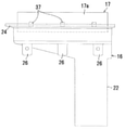
図1は、下記特許文献1に開示された橋梁用排水桝の要部構造を示すもので、橋梁のコンクリート製床版1の上端が床版1とほぼ面一となる程度まで埋設されるFRP製の下桝2と、該下桝2の肉厚部2aに埋設され、数か所に袋状の長ナット3を縦向きに溶接して固着した鋼製のリング枠4と、各長ナット3にそれぞれ高さ調整して捩じ込まれるボルト5と、下桝2の開口7内に嵌め込まれ、上端より外側方に突出するフランジ6aで下桝2の数か所より突出するボルト5上に支持される鋼製の上桝6と、該上桝6の開口9内に装着される図示しない排水蓋(グレーチング)と、前記下桝2の下部に接続される図示しない排水パイプと、下桝周囲の水を下桝内に導く樹脂製のフィルターチューブ(水透過性フィルター)7とよりなっている。図中、8は床版1上に下枠上端面に至るまで被せて敷設される防水シートであり、11は上桝取付後、防水シート8上に形成される透水性のアスファルト層で、該アスファルト層上面は図示するように排水桝に向け雨水が流入し易いように勾配が付けられている。
FIG. 1 shows the main part structure of the drainage basin for a bridge disclosed in Patent Document 1 below, and is an FRP in which the upper end of the concrete deck 1 of the bridge is buried to the extent that it is almost flush with the deck 1. A
図1に示す排水桝には、次のような問題がある。
(1)ボルト5は、透水性のアスファルト層11を浸透した水との接触により腐食し易く、腐食すると交換する必要があるが、ボルト5は上桝6のフランジ6a下に位置してアスファルト層11に埋め込まれているため、腐食の確認ができない。定期的に交換するにしても、上桝6を取外してから所要部のアスファルト層11をはつって除去せねばならない。またアスファルト層11の形成や除去もボルト5が邪魔となりがちで、除去に際しては防水シート8も損傷され易くなり、損傷されるとコンクリート製床版1への浸水が生じ易くなる。
The drainage basin shown in FIG. 1 has the following problems.
(1) The
(2)防水シート8の施工時、防水シート8を下枠上端面に至るまで敷設するには、ボルト5に当たる箇所の防水シート8を切欠く必要があり、手間がかかるうえ、防水シート8が敷かれる下桝上面は平坦であるため、防水シート8と下桝下端面との間より侵入した水がコンクリート製床版1に達し、該床版1に浸透して床版1を劣化させるおそれがある。
(2) When constructing the
(3)上桝6はフィルターチューブ7を下桝上端面に装着後、下桝2の開口内に嵌め込まれるが、この際、フィルターチューブ7が下桝2の開口内にはみ出して上桝嵌着時の邪魔となるおそれがあり、またフィルターチューブ7の交換は、上桝6を取外すと共に、フィルターチューブ7に接するアスファルト層11を除去する必要がある。
(3) The
(4)排水蓋が装着される上桝6はボルト5上に載置して支持されているだけであるため、上桝6や該上桝6に装着の排水蓋は盗難のおそれがあるうえ、排水桝上を車両が走行する際、上桝6が排水蓋と共に跳ね上がって飛び出すおそれがあり、飛び出さないまでも上下動や横方向にずれてガタガタし、騒音を生じ易い。
(4) Since the
本発明は上記の問題を解消すべく改良された橋梁用排水桝の取付構造を提供することを目的とする。 It is an object of the present invention to provide an improved mounting structure for a drainage basin for a bridge in order to solve the above problems.
請求項1に係る発明は、上部に開口部を備えた排水用下桝16と、該下桝16の数か所に下桝16と一体をなして設けら れるナット27にそれぞれ捩じ込んで開口部内に縦設される第2のボルトと、前記下桝16 の開口部内に嵌着され、底部において前記第2のボルト44に支持される受枠17と、該受枠 17に装着される排水蓋18とよりなる排水桝の橋梁への取付構造であって、前記下桝16が埋 設される橋梁のコンクリート製床版53と、該床版上に形成される防水層54と、該防水層上 に前記受枠17の側壁17aと接し、かつ受枠上端以上の高さのレベルまで形成されるアスファルト層55よりなり、前記受枠17と排水蓋18のうち、受枠17は下桝16に第1のボルト46に て連結し一体化される一方、前記排水蓋18は受枠17に第3のボルト38にて連結し一体化される橋梁用排水桝の取付構造において、前記下桝16には上端より外側方に先端に向かって上向きに傾斜し、表面に前記防水層54
が形成されるフランジ24が突設され、前記受枠17の側壁17aには受枠外の水を受枠内に通す通水孔37が形成されると共に、前記フランジ上には前記通水孔37に当てがわれる水透過性フィルター51が装着され、しかも前記受枠17の側壁17aは垂直をなし、外側方への突出部を有しないことを特徴とする。
The invention according to claim 1 is screwed into a drainage
請求項2に係る発明は、請求項1に係る発明において、前記排水蓋はグレーチング18であり、受枠17はグレーチング18を支持するフランジ32を内側方に向けて突出形成し、フランジ間が開口することを特徴とする。
The invention according to
請求項1に係る発明によると、下桝の開口部内に嵌着される受枠の底部を支持する第2のボルトは受枠の内側に位置し、受枠外にないため、アスファルト層及び防水層の形成時 に第2のボルトが邪魔となることがなく、したがってアスファルト形成時及び防水層形成 時の作業性がよくなる。また第2のボルトの交換は、受枠を取り外すことにより比較的容 易に行うことができる。また受枠と排水蓋は第1及び第3のボルトを介して下桝に固定さ れるため、盗難防止となり、また車両の走行により受枠と共に排水蓋が跳ね上がって飛び 出す危険性が解消され、跳ね上がってガタ付いたり、受枠が下枠内でずれ動いたり、排水 蓋が受枠内でずれ動いて受枠に衝突することによる騒音も防止される。しかも下桝のフランジは内側が下向きに傾斜しているため、フランジやフランジ上に形成される防水層上に達した水が下桝内に流入し易くなり、またフランジと防水層、とりわけ防水層を防水シートで構成する場合のフランジと防水シートとの間より侵入した水がコンクリート製床版に達し難くなり、コンクリート製床版の水との接触による劣化を解消することができる。また受枠外側面には水透過性フィルターを脱着する際の障害となりがちな突出部がないため、水透過性フィルターを受枠の周りに装着したり取り外すのが容易となり、水透過性フィルターの交換もアスファルト層の一部を除去するだけで受枠を取り外すことなく行うことができる。
According to the invention of claim 1, since the second bolt supporting the bottom of the receiving frame fitted in the opening of the lower box is located inside the receiving frame and not outside the receiving frame, the asphalt layer and the waterproof layer are formed. Sometimes the second bolt does not get in the way, thus improving workability during asphalt formation and waterproof layer formation. Further, the replacement of the second bolt can be performed relatively easily by removing the receiving frame. In addition, since the receiving frame and drain lid are fixed to the lower basin via the first and third bolts, theft is prevented, and the danger that the drain lid jumps up with the receiving frame and pops out due to the running of the vehicle is eliminated, and it jumps up. Noise caused by rattling, the receiving frame shifting in the lower frame, and the drainage lid shifting in the receiving frame and colliding with the receiving frame is also prevented. Moreover , since the flange of the lower basin is inclined downward inward, water that has reached the flange and the waterproof layer formed on the flange easily flows into the lower basin, and the flange and the waterproof layer, especially the waterproof layer, When the waterproof sheet is used, the water that has entered between the flange and the waterproof sheet is less likely to reach the concrete floor slab, and the deterioration of the concrete floor slab due to contact with water can be eliminated. In addition, since there are no protrusions on the outer surface of the receiving frame that tend to be obstacles when attaching or detaching the water permeable filter, it is easy to attach or remove the water permeable filter around the receiving frame, and the water permeable filter can be replaced. This can be done by removing only a part of the asphalt layer without removing the receiving frame.
請求項2に係る発明によると、第1及び第2のボルトはグレーチング及び受枠のフランジ間の開口を通して視認することができ、腐食の有無やその程度を確認することができる。 According to the second aspect of the present invention, the first and second bolts can be visually recognized through the grating and the opening between the flanges of the receiving frame, and the presence or absence of corrosion and the degree thereof can be confirmed.
以下、橋梁に設置される排水桝の構造について図面により説明する。
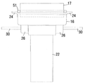
図2は、全体を符号15で示す排水桝の平面図、図3は同正面図、図4は同側面図、図5は同断面図、図6は図2のA-A線での断面図で、排水桝15は下桝16と、該下桝16に嵌着される受枠17と、該受枠17に装着される排水蓋としてのグレーチング18を基本構造とし、以下これら下桝16、受枠17及びグレーチング18について詳述する。
Hereinafter, the structure of the drainage basin installed on the bridge will be described with reference to the drawings.
FIG. 2 is a plan view of the drainage basin indicated by
下桝16は鋼製であってもよいが、好ましくは軽量化のため全体をFRP製としたもので、上部は漏斗状で、矩形の開口部21を備え、下部が図3~図6には図示していないが
、橋梁のコンクリート製床版を通って該床板下に突出する横断面円形の排水部22となり、該排水部22は図3及び図5に示すように開口部21の一側寄り(図3及び図5に示す例においては右側寄り)に偏寄して一体形成されている。図示する例において、排水部22は全体が一体形成されているが、下側部を分割して別体の排水パイプとし、上側部に例えば接着により連結して一体に接続した構成をなすようにしてもよい。
The
前記開口部21は図5に示すように、底が一側端より矩形の平坦部16a(図2参照)に向かって下向きに傾斜し、平坦部16aに排水部上端の排水口22aが開口し、開口部内に流入した水が排水口22aを経て排水部22に流出できるようにしてある。
As shown in FIG. 5, the
開口部上端の下桝上端には、前後左右に外側方に突出するフランジ24が一体形成され(図2、図3及び図5において、右側のフランジ24は巾狭になっているが、他のフランジ24と同一巾に形成されていてもよい)、フランジ24はいずれも先端に向かって上向きに傾斜して形成されている。
A
開口部21はまた、長辺側(図5においては前後、図6においては左右)に内側に突出する段25を形成し、該段下には、段25の両端部と中央部の三か所に肉厚部26を形成し、各肉厚部26に鋼製の長ナット27が縦向きに埋設されている(図6及び図7参照)。図示する例において長ナット27は下面がFRP材で覆われ、上面はネジ孔が肉厚部26に形成の差込孔28を通じて開口しているが、少なくとも上面を段25と面一にするか、段25より突出させておいてもよい。長ナット27にはまた、図1に示すような袋状のナットを用いてもよい。
The
肉厚部26に埋設される長ナット27にはまた、外側方に横向きに突出するナット29が溶接にて固着され、該ナット29はネジ孔が開口し、後述のコンクリート製床版に配筋される鉄筋30の端部がネジ孔に捩じ込まれ(図7)、或いは差込んで取付けられるようにしてある。
A
受枠17は鋼製で、前記下桝16の開口部21に若干の遊びを存して嵌着される平面視で、開口部21と相似形の矩形をなし、対向する長辺側の側壁17aの下側部にはそれぞれ内側方に突出し、互いに向き合って形成され、受枠底部に相当するフランジ32を有し(図8及び図9)、両フランジ32には長手方向の中央に側壁17aに沿った形状の長孔33が、両側にボルト通し孔34がそれぞれ形成され、フランジ32下にはネジ孔をボルト通し孔34と合致させたナット35が固着されている(図5参照)。そしてフランジ32上の前記側壁17aには、外部の水を受枠内に流入させるための通水孔である長孔37が定間隔で複数、縦向きに形成されている(図9)。
The receiving
受枠17に装着されるグレーチング18は図2に示すように、短辺と平行に等間隔で配置されるベアリングバー18aと、該ベアリングバー18aの両端に連結される端板18bと、該端板18bと平行で、かつ前記ベアリングバー18aと直交して等間隔でベアリングバー18aに固着のツイストバー18cよりなり、グレーチング下面の端板側縁には鋼製のフラットバー39が溶接にて固着されると共に、フラットバー下の長手方向両サイドにフラットバー39と同一巾の硬質ゴム板41が接着にて取付けてある(図5及び図6参照)。両側の硬質ゴム板41はフラットバー中央で一定の隙間を存して引離され、また硬質ゴム板41の肉厚が第1のボルト46のボルト頭部46aの高さと同一ないし若干厚く形成されていることから、両側のゴム板41端面と、フラットバー39とで形成された凹所42に前記ボルト頭部46aが納まりうるようにしてある。
As shown in FIG. 2 , the grating 18 mounted on the receiving
フラットバー39と硬質ゴム板41の両側には、受枠17のフランジ32両側に形成されるボルト通し孔34と対応する箇所にスリーブ36が密嵌して取付けてあり、スリーブ
36には後述のボルト38が通され、図2に示すようにグレーチング18の第3のボルト38のボルト頭部38aが納まる箇所のベアリングバー18aは部分的に切除されている。図2に示す40はフラットバー側端面に溶接されて立ち上がり、ベアリングバー18aの両端を固着する取付板である。
On both sides of the
前記フラットバー39と、ゴム板41はグレーチング18の嵩上げ材としての機能を果たし、ゴム板41は緩衝材としての機能を果たすが、グレーチング18は後述するように受枠17に第3のボルト38にて連結され、受枠17は更に下桝16に第1のボルト46にて連結され、跳ね上がりや横ずれが防止されるため、本来ガタ付いて騒音を生ずることはないが、ゴム板41を設けたのはボルトやナットの緩みによりグレーチング18が上下動して受枠17に対しガタつきを生じた場合のことを考慮したもので、ゴム板41に代え、鋼板を用いて嵩上げしても支障はない。鋼板を用いる場合、フラットバー39と一体形成し、前記凹所42と同様、中央にボルト頭部が納まる凹所が形成される。
The
排水桝15の基本構造をなす下桝16、受枠17及びグレーチング18は以上のように構成され、橋梁での施工は次のようにして行われる。
The
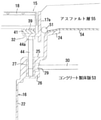
橋梁の床版形成箇所に設定された所要部に下桝16を設置し、床版形成箇所に配筋された鉄筋30の端部を下桝16の前記肉厚部26に埋設されるナット29に捩じ込み(図7、図10)、或いは差込む。その後図5、図6及び図10に示すように、下桝四隅の肉厚部26に埋設の長ナット27に第2のボルト44の下側部を捩じ込み、捩込量の調整によりボルト頭部44aの高さを調整して段25より上向きに縦設させる。そしてボルト頭部上に下桝開口部21に若干の遊びを存して嵌着した受枠17の受枠底部としてのフランジ32を載せて支持させる。
A
次に受枠17のフランジ32中央部に形成の長孔33に第1のボルト46を通し、フランジ32よりフランジ下に突出するボルト下端からナット47を適当量捩じ込んでおき、前記第1のボルト46を長孔内で位置調整して段25中央部の肉厚部26に埋設のナット27にボルト頭部46aがフランジ32に当たるまで捩じ込む。その後、ナット47を捩じ込み、ボルト頭部46aとナット47とでフランジ32を挟み込み固定する。これによりフランジ32がボルト頭部44aに当たって四隅が第2のボルト44により支持される受枠17が下桝16に連結され固定される(図5参照)。
Next, the
次に端板側下側縁にフラット39と硬質ゴム板41を積層して取付けたグレーチング18が凹所42内にボルト頭部46aが納まるようにして受枠内に若干の遊びを存して装着され、装着後、グレーチング四隅のスリーブ36に挿入した第3のボルト38のフランジ32より下向きに突出するボルト端にはナット35が捩じ込まれ、ボルト頭部38aとナット35とでフラットバー39と硬質ゴム板41と受枠17のフランジ32とを上下より挟み込んで固定する。これによりグレーチング18と受枠17が連結されて一体化され、かつ受枠17が前述するように、下桝16に前記第1のボルト46により連結されて一体化されることにより、排水桝15全体が一体化されるようになっている。
Next, the grating 18 attached by laminating the flat 39 and the
前述するようにして排水桝15が組付けられたのち、透水性フィルターであるフィルターチューブ51が受枠17の周囲に長孔37を塞ぎ、かつ下桝16のフランジ24に当たるようにして取付けられ、フランジ24上に達した水がフィルターチューブ51及び図9に示す長孔37を通り、下桝内に流入されるようにしてある。なお、フィルターチューブ51は中空状をなしているが中実であってもよい。
After the
排水桝埋設後、フランジ24の先端レベルまでコンクリートが打設され養生により、コンクリート製床版53を形成したのち、該床版53とフランジ24上にフィルターチューブ51に達するまで防水シート54を被せて防水層を形成し、その上に透水性のアスファルト層55を形成する(図10)。アスファルト層55の形成は路面のレベルが受枠17よりも高く、路面が排水桝15に向かって排水桝側が下がるように傾斜し、排水桝側端のエッジのアスファルトは損傷を防ぐため図示するように面取りされている。
After burying the drainage basin, concrete is poured up to the tip level of the
前述の例では、コンクリート製床版53と、アスファルト層55は排水桝組付後に形成されるようになっているが、排水桝15の組付時に組み込んで、例えば下桝16の設置後にコンクリートを打設してコンクリート製床版53を形成し、その後受枠17を下桝16に嵌着し、フィルターチューブ51を取付けたのち、アスファルト層55を形成するようにしてもよい。この場合、グレーチング18はアスファルト層55の形成に前後して受枠17に装着される。
In the above example, the concrete floor slab 53 and the asphalt layer 55 are formed after the drainage basin is assembled, but they are incorporated at the time of assembling the
前記実施形態では、受枠17と下桝16は第1のボルト46により連結され、グレーチング18と受枠17は第3のボルト38により連結されているが、第3のボルト38をグレーチング18と一体のフラットバー39及び硬質ゴム板41のスリーブ36に通し、更に受枠17のフランジ32に通したのち、下桝16の肉厚部26に埋設の長ナット27に捩じ込むように構成することも可能である。
In the above embodiment, the receiving
前記実施形態では、コンクリート製床版53上の防水層は防水シート54により形成されているが、コンクリート製床版53上に防水塗装により形成することもできる。
In the above embodiment, the waterproof layer on the concrete floor slab 53 is formed by the
15・・排水桝
16・・下桝
17・・受枠
18・・グレーチング
21・・開口部
22・・排水部
24、32・・フランジ
25・・段
26・・肉厚部
27・・長ナット
29、35、47・・ナット
30・・鉄筋
33、37・・長孔
34・・ボルト通し孔
36・・スリーブ
38・・第3のボルト
44・・第2のボルト
46・・第1のボルト
39・・フラットバー
41・・硬質ゴム板
42・・凹所
51・・フィルターチューブ
53・・コンクリート製床版
54・・防水シート
55・・アスファルト層
15 ・ ・
Claims (2)
The drainage basin for a bridge according to claim 1 , wherein the drainage lid is a grating 18, and the receiving frame 17 has a flange 32 that supports the grating 18 projecting inward and an opening between the flanges . Mounting structure.
Priority Applications (1)
| Application Number | Priority Date | Filing Date | Title |
|---|---|---|---|
| JP2017026526A JP7017003B2 (en) | 2017-02-16 | 2017-02-16 | Installation structure of drainage basin for bridges |
Applications Claiming Priority (1)
| Application Number | Priority Date | Filing Date | Title |
|---|---|---|---|
| JP2017026526A JP7017003B2 (en) | 2017-02-16 | 2017-02-16 | Installation structure of drainage basin for bridges |
Publications (2)
| Publication Number | Publication Date |
|---|---|
| JP2018131823A JP2018131823A (en) | 2018-08-23 |
| JP7017003B2 true JP7017003B2 (en) | 2022-02-08 |
Family
ID=63248073
Family Applications (1)
| Application Number | Title | Priority Date | Filing Date |
|---|---|---|---|
| JP2017026526A Active JP7017003B2 (en) | 2017-02-16 | 2017-02-16 | Installation structure of drainage basin for bridges |
Country Status (1)
| Country | Link |
|---|---|
| JP (1) | JP7017003B2 (en) |
Citations (6)
| Publication number | Priority date | Publication date | Assignee | Title |
|---|---|---|---|---|
| JP3145674B2 (en) | 1997-12-09 | 2001-03-12 | 橋梁技建株式会社 | FRP drainage basin for bridge |
| JP2001132083A (en) | 1999-11-09 | 2001-05-15 | Daicel Chem Ind Ltd | Method for manufacturing catch basin |
| JP2002294853A (en) | 2001-03-28 | 2002-10-09 | Takushin Eng Kk | Catch basin |
| JP2005248426A (en) | 2004-03-01 | 2005-09-15 | Sho Bond Constr Co Ltd | Drainage device for road structure |
| JP2015105486A (en) | 2013-11-29 | 2015-06-08 | 株式会社大城 | Catch basin |
| JP2015129420A (en) | 2014-01-09 | 2015-07-16 | エコ ジャパン株式会社 | Embedded structure, method for constructing embedded structure, and display plate |
Family Cites Families (2)
| Publication number | Priority date | Publication date | Assignee | Title |
|---|---|---|---|---|
| JP2813730B2 (en) * | 1994-12-27 | 1998-10-22 | 昭和シェル石油株式会社 | Secondary drainage system for road bridge |
| CZ200890A3 (en) * | 2008-02-19 | 2009-09-02 | Bridge drainer with variable connection |
-
2017
- 2017-02-16 JP JP2017026526A patent/JP7017003B2/en active Active
Patent Citations (6)
| Publication number | Priority date | Publication date | Assignee | Title |
|---|---|---|---|---|
| JP3145674B2 (en) | 1997-12-09 | 2001-03-12 | 橋梁技建株式会社 | FRP drainage basin for bridge |
| JP2001132083A (en) | 1999-11-09 | 2001-05-15 | Daicel Chem Ind Ltd | Method for manufacturing catch basin |
| JP2002294853A (en) | 2001-03-28 | 2002-10-09 | Takushin Eng Kk | Catch basin |
| JP2005248426A (en) | 2004-03-01 | 2005-09-15 | Sho Bond Constr Co Ltd | Drainage device for road structure |
| JP2015105486A (en) | 2013-11-29 | 2015-06-08 | 株式会社大城 | Catch basin |
| JP2015129420A (en) | 2014-01-09 | 2015-07-16 | エコ ジャパン株式会社 | Embedded structure, method for constructing embedded structure, and display plate |
Also Published As
| Publication number | Publication date |
|---|---|
| JP2018131823A (en) | 2018-08-23 |
Similar Documents
| Publication | Publication Date | Title |
|---|---|---|
| US7413372B2 (en) | Trench drain frame and grate assembly | |
| KR101088163B1 (en) | Drain-pipe for bridge and construction process thereof | |
| KR100877322B1 (en) | Method for manufacturing a assembly type manhole with complex function and assembly type manhole with complex function using the same | |
| US7670080B2 (en) | Catch basin system | |
| JP7017003B2 (en) | Installation structure of drainage basin for bridges | |
| KR200489711Y1 (en) | Prefabricated trench | |
| JP5388733B2 (en) | Simple drainage member, simple drainage device and construction method thereof | |
| JP2007092315A (en) | Side ditch unit and grating lid making use therefor | |
| JP3145674B2 (en) | FRP drainage basin for bridge | |
| JP3130944U (en) | Cross-type side gutter unit and side drainage type grating lid that do not require iron frame and iron receiving frame | |
| JP2004169375A (en) | Drain gutter structure | |
| KR101228375B1 (en) | The union structure of the grating | |
| JP6153187B1 (en) | Road bridge cover widening unit | |
| JP5010770B2 (en) | Side gutter construction method with water collection performance and water collecting fitting used in the construction method | |
| JP5534503B2 (en) | L-shaped side groove block | |
| JP2011174292A (en) | U-shaped side ditch block equipped with overflow pipe, and roadside ditch using the same | |
| JP3127873U (en) | Side groove and lid structure | |
| KR20150133455A (en) | Polyethylene side gutter | |
| KR200497031Y1 (en) | manhole cover | |
| JP4569805B2 (en) | Mounting structure of groove lid to U-shaped groove | |
| JP6318384B2 (en) | Water shielding device | |
| JP3125818U (en) | Side groove unit and grating lid structure | |
| KR101606424B1 (en) | Gutter structure and construction method for pavement | |
| JP2007308954A (en) | Gully unit for drainage and grating lid used therefor | |
| JP3182522U (en) | Gutter |
Legal Events
| Date | Code | Title | Description |
|---|---|---|---|
| A711 | Notification of change in applicant |
Free format text: JAPANESE INTERMEDIATE CODE: A711 Effective date: 20180627 |
|
| A521 | Request for written amendment filed |
Free format text: JAPANESE INTERMEDIATE CODE: A821 Effective date: 20180628 |
|
| A621 | Written request for application examination |
Free format text: JAPANESE INTERMEDIATE CODE: A621 Effective date: 20200203 |
|
| A977 | Report on retrieval |
Free format text: JAPANESE INTERMEDIATE CODE: A971007 Effective date: 20201130 |
|
| A131 | Notification of reasons for refusal |
Free format text: JAPANESE INTERMEDIATE CODE: A131 Effective date: 20201208 |
|
| A521 | Request for written amendment filed |
Free format text: JAPANESE INTERMEDIATE CODE: A523 Effective date: 20210127 |
|
| A131 | Notification of reasons for refusal |
Free format text: JAPANESE INTERMEDIATE CODE: A131 Effective date: 20210615 |
|
| A521 | Request for written amendment filed |
Free format text: JAPANESE INTERMEDIATE CODE: A523 Effective date: 20210730 |
|
| TRDD | Decision of grant or rejection written | ||
| A01 | Written decision to grant a patent or to grant a registration (utility model) |
Free format text: JAPANESE INTERMEDIATE CODE: A01 Effective date: 20211221 |
|
| A61 | First payment of annual fees (during grant procedure) |
Free format text: JAPANESE INTERMEDIATE CODE: A61 Effective date: 20211223 |
|
| R150 | Certificate of patent or registration of utility model |
Ref document number: 7017003 Country of ref document: JP Free format text: JAPANESE INTERMEDIATE CODE: R150 |