JP7015284B2 - Water spray cooling device - Google Patents

Water spray cooling device Download PDF

Info

Publication number
JP7015284B2
JP7015284B2 JP2019163191A JP2019163191A JP7015284B2 JP 7015284 B2 JP7015284 B2 JP 7015284B2 JP 2019163191 A JP2019163191 A JP 2019163191A JP 2019163191 A JP2019163191 A JP 2019163191A JP 7015284 B2 JP7015284 B2 JP 7015284B2
Authority
JP
Japan
Prior art keywords
water
guide
portions
guide portion
radiator
Prior art date
Legal status (The legal status is an assumption and is not a legal conclusion. Google has not performed a legal analysis and makes no representation as to the accuracy of the status listed.)
Active
Application number
JP2019163191A
Other languages
Japanese (ja)
Other versions
JP2020056564A (en
JP2020056564A5 (en
Inventor
善仁 嘉田
一稔 若月
正克 坪内
Current Assignee (The listed assignees may be inaccurate. Google has not performed a legal analysis and makes no representation or warranty as to the accuracy of the list.)
Denso Corp
Toyota Motor Corp
Original Assignee
Denso Corp
Toyota Motor Corp
Priority date (The priority date is an assumption and is not a legal conclusion. Google has not performed a legal analysis and makes no representation as to the accuracy of the date listed.)
Filing date
Publication date
Application filed by Denso Corp, Toyota Motor Corp filed Critical Denso Corp
Priority to PCT/JP2019/036874 priority Critical patent/WO2020066864A1/en
Publication of JP2020056564A publication Critical patent/JP2020056564A/en
Publication of JP2020056564A5 publication Critical patent/JP2020056564A5/ja
Priority to US17/209,448 priority patent/US20210207891A1/en
Application granted granted Critical
Publication of JP7015284B2 publication Critical patent/JP7015284B2/en
Active legal-status Critical Current
Anticipated expiration legal-status Critical

Links

Images

Classifications

    • FMECHANICAL ENGINEERING; LIGHTING; HEATING; WEAPONS; BLASTING
    • F28HEAT EXCHANGE IN GENERAL
    • F28DHEAT-EXCHANGE APPARATUS, NOT PROVIDED FOR IN ANOTHER SUBCLASS, IN WHICH THE HEAT-EXCHANGE MEDIA DO NOT COME INTO DIRECT CONTACT
    • F28D5/00Heat-exchange apparatus having stationary conduit assemblies for one heat-exchange medium only, the media being in contact with different sides of the conduit wall, using the cooling effect of natural or forced evaporation
    • F28D5/02Heat-exchange apparatus having stationary conduit assemblies for one heat-exchange medium only, the media being in contact with different sides of the conduit wall, using the cooling effect of natural or forced evaporation in which the evaporating medium flows in a continuous film or trickles freely over the conduits
    • FMECHANICAL ENGINEERING; LIGHTING; HEATING; WEAPONS; BLASTING
    • F28HEAT EXCHANGE IN GENERAL
    • F28FDETAILS OF HEAT-EXCHANGE AND HEAT-TRANSFER APPARATUS, OF GENERAL APPLICATION
    • F28F25/00Component parts of trickle coolers
    • F28F25/02Component parts of trickle coolers for distributing, circulating, and accumulating liquid
    • F28F25/04Distributing or accumulator troughs
    • HELECTRICITY
    • H01ELECTRIC ELEMENTS
    • H01MPROCESSES OR MEANS, e.g. BATTERIES, FOR THE DIRECT CONVERSION OF CHEMICAL ENERGY INTO ELECTRICAL ENERGY
    • H01M8/00Fuel cells; Manufacture thereof
    • H01M8/04Auxiliary arrangements, e.g. for control of pressure or for circulation of fluids
    • H01M8/04007Auxiliary arrangements, e.g. for control of pressure or for circulation of fluids related to heat exchange
    • H01M8/04029Heat exchange using liquids
    • HELECTRICITY
    • H01ELECTRIC ELEMENTS
    • H01MPROCESSES OR MEANS, e.g. BATTERIES, FOR THE DIRECT CONVERSION OF CHEMICAL ENERGY INTO ELECTRICAL ENERGY
    • H01M8/00Fuel cells; Manufacture thereof
    • H01M8/04Auxiliary arrangements, e.g. for control of pressure or for circulation of fluids
    • H01M8/04007Auxiliary arrangements, e.g. for control of pressure or for circulation of fluids related to heat exchange
    • H01M8/04067Heat exchange or temperature measuring elements, thermal insulation, e.g. heat pipes, heat pumps, fins
    • H01M8/04074Heat exchange unit structures specially adapted for fuel cell
    • FMECHANICAL ENGINEERING; LIGHTING; HEATING; WEAPONS; BLASTING
    • F28HEAT EXCHANGE IN GENERAL
    • F28DHEAT-EXCHANGE APPARATUS, NOT PROVIDED FOR IN ANOTHER SUBCLASS, IN WHICH THE HEAT-EXCHANGE MEDIA DO NOT COME INTO DIRECT CONTACT
    • F28D21/00Heat-exchange apparatus not covered by any of the groups F28D1/00 - F28D20/00
    • F28D2021/0019Other heat exchangers for particular applications; Heat exchange systems not otherwise provided for
    • F28D2021/0043Other heat exchangers for particular applications; Heat exchange systems not otherwise provided for for fuel cells
    • FMECHANICAL ENGINEERING; LIGHTING; HEATING; WEAPONS; BLASTING
    • F28HEAT EXCHANGE IN GENERAL
    • F28FDETAILS OF HEAT-EXCHANGE AND HEAT-TRANSFER APPARATUS, OF GENERAL APPLICATION
    • F28F2245/00Coatings; Surface treatments
    • F28F2245/02Coatings; Surface treatments hydrophilic
    • YGENERAL TAGGING OF NEW TECHNOLOGICAL DEVELOPMENTS; GENERAL TAGGING OF CROSS-SECTIONAL TECHNOLOGIES SPANNING OVER SEVERAL SECTIONS OF THE IPC; TECHNICAL SUBJECTS COVERED BY FORMER USPC CROSS-REFERENCE ART COLLECTIONS [XRACs] AND DIGESTS
    • Y02TECHNOLOGIES OR APPLICATIONS FOR MITIGATION OR ADAPTATION AGAINST CLIMATE CHANGE
    • Y02EREDUCTION OF GREENHOUSE GAS [GHG] EMISSIONS, RELATED TO ENERGY GENERATION, TRANSMISSION OR DISTRIBUTION
    • Y02E60/00Enabling technologies; Technologies with a potential or indirect contribution to GHG emissions mitigation
    • Y02E60/30Hydrogen technology
    • Y02E60/50Fuel cells

Description

本発明は、熱交換器に水を散布することによって、熱交換器の冷却能力を向上させる水散布冷却装置に関する。 The present invention relates to a water spray cooling device that improves the cooling capacity of a heat exchanger by spraying water on the heat exchanger.

従来、燃料電池システム等においては、燃料電池を冷却する為の熱交換器(例えば、ラジエータ)に水を散布する水散布冷却装置が用いられている。例えば特許文献1に記載された水散布冷却装置では、散布装置から熱交換器に水を散布することで、水の蒸発潜熱を利用して熱交換器の冷却能力を向上させている。 Conventionally, in a fuel cell system or the like, a water spray cooling device for spraying water on a heat exchanger (for example, a radiator) for cooling a fuel cell has been used. For example, in the water spray cooling device described in Patent Document 1, water is sprayed from the spray device to the heat exchanger to improve the cooling capacity of the heat exchanger by utilizing the latent heat of evaporation of water.

特開2002-372385号公報Japanese Patent Application Laid-Open No. 2002-372385

しかしながら、従来の水散布冷却装置では、隣接する供給孔から流出した水同士が表面張力によって合体して大きな水滴にならなければ、散布装置から離脱しない。このため、散布装置からラジエータ放熱面の偏った箇所に水が過剰に供給される。 However, in the conventional water spray cooling device, the water flowing out from the adjacent supply holes does not separate from the spray device unless it is united by surface tension to form a large water droplet. Therefore, water is excessively supplied from the spraying device to the uneven portion of the radiator heat dissipation surface.

ラジエータ放熱面の偏った箇所に過剰に供給された水がラジエータ背面に移動すると、ラジエータ背面では多量の水が同じ高さから同時期に流れ落ちるため、厚い水膜が成形されやすくなる。ラジエータ背面で厚い水膜が成形されると、ラジエータを通過する風の妨げとなり、ラジエータ背面の水が風によって後方へ吹飛ばされる。この結果、散布装置からラジエータ放熱面に散布された水の多くが、蒸発することなく風で吹飛ばされ、水散布冷却装置による冷却効率が低下する。 When the water excessively supplied to the uneven portion of the radiator heat dissipation surface moves to the back surface of the radiator, a large amount of water flows down from the same height at the same time on the back surface of the radiator, so that a thick water film is easily formed. When a thick water film is formed on the back surface of the radiator, it hinders the wind passing through the radiator, and the water on the back surface of the radiator is blown backward by the wind. As a result, most of the water sprayed from the spraying device to the radiator heat radiation surface is blown off by the wind without evaporating, and the cooling efficiency of the water spray cooling device is lowered.

本発明は上記点に鑑み、熱交換器に水を散布し、熱交換器の冷却能力を向上させる水散布冷却装置において、熱交換器に均一に水を散布することを目的とする。 In view of the above points, it is an object of the present invention to uniformly spray water on the heat exchanger in a water spray cooling device that sprays water on the heat exchanger and improves the cooling capacity of the heat exchanger.

上記目的を達成するため、請求項1に記載の発明では、予め定められた送風方向へ流れる空気と内部を流通する熱媒体との間で熱交換を行う熱交換器(13)に対し、送風方向の上流側から水を散布する散布装置(20)を備え、散布装置は、熱交換器に散布される水を供給する供給孔(206)と、供給孔から重力方向下側に延びるように形成され、供給孔から供給される水を誘導するガイド部(207、208)とを含んでおり、供給孔は複数設けられており、ガイド部は複数の供給孔のそれぞれに対応して設けられており、隣接するガイド部は、それぞれ長さが異なっていることを特徴とする。 In order to achieve the above object, in the invention according to claim 1, the air is blown to the heat exchanger (13) that exchanges heat between the air flowing in the predetermined blowing direction and the heat medium flowing inside. A spraying device (20) for spraying water from the upstream side in the direction is provided, and the spraying device has a supply hole (206) for supplying water to be sprayed to the heat exchanger and extends downward from the supply hole in the direction of gravity. It includes a guide portion (207, 208) that is formed and guides water supplied from the supply hole, a plurality of supply holes are provided, and a guide portion is provided corresponding to each of the plurality of supply holes. The adjacent guide portions are characterized in that they have different lengths .

本発明によれば、ガイド部を設けることで、供給孔から供給される水が大きな液滴に成長する前に熱交換器に水を散布することができる。これにより、熱交換器に水を均一に散布でき、熱交換器の背面で厚い水膜が形成されにくくなる。このため、熱交換器の背面から後方へ吹飛ばされる水の量を低減させることができ、熱交換器の冷却能力を向上させることができる
さらに、本発明では、ガイド部が複数の供給孔のそれぞれに対応して設けられている。これにより、ガイド部の大きさをできるだけ小さくすることができ、ガイド部による通風抵抗をできるだけ小さくすることができる。
According to the present invention, by providing the guide portion, the water supplied from the supply hole can be sprayed on the heat exchanger before it grows into large droplets. As a result, water can be evenly sprayed on the heat exchanger, and a thick water film is less likely to be formed on the back surface of the heat exchanger. Therefore, the amount of water blown from the back surface of the heat exchanger to the rear can be reduced, and the cooling capacity of the heat exchanger can be improved. Further, in the present invention, the guide portion has a plurality of supply holes. It is provided corresponding to each. As a result, the size of the guide portion can be made as small as possible, and the ventilation resistance by the guide portion can be made as small as possible.

なお、上記各構成要素の括弧内の符号は、後述する実施形態に記載の具体的手段との対応関係を示すものである。 The reference numerals in parentheses of each of the above components indicate the correspondence with the specific means described in the embodiments described later.

第1実施形態の燃料電池システムの構成図である。It is a block diagram of the fuel cell system of 1st Embodiment. 第1実施形態の散布装置の正面図である。It is a front view of the spraying apparatus of 1st Embodiment. 第1実施形態の散布装置の斜視図である。It is a perspective view of the spraying apparatus of 1st Embodiment. 第1実施形態の散布装置の一部を拡大した斜視図である。It is an enlarged perspective view of a part of the spraying apparatus of 1st Embodiment. 第1実施形態の散布装置の一部を拡大した側面図である。It is an enlarged side view of a part of the spraying apparatus of 1st Embodiment. 図5のVI-VI断面図である。FIG. 5 is a sectional view taken along line VI-VI of FIG. 第1実施形態のラジエータ及び散布装置の側面図である。It is a side view of the radiator and the spraying apparatus of 1st Embodiment. 第2実施形態のラジエータ及び散布装置の側面図である。It is a side view of the radiator and the spraying apparatus of 2nd Embodiment. 第3実施形態の散布装置の一部を拡大した側面図である。It is an enlarged side view of a part of the spraying apparatus of 3rd Embodiment. 第3実施形態のラジエータ及び散布装置の側面図である。It is a side view of the radiator and the spraying apparatus of 3rd Embodiment. ラジエータの冷却性能を示すグラフである。It is a graph which shows the cooling performance of a radiator. 第4実施形態のラジエータ及び散布装置の側面図である。It is a side view of the radiator and the spraying apparatus of 4th Embodiment. 第5実施形態の散布装置を部分的に拡大した正面図である。It is a partially enlarged front view of the spraying apparatus of 5th Embodiment. 図13のXIV-XIV断面図である。FIG. 13 is a cross-sectional view taken along the line XIV-XIV of FIG. 溝部の変形例を示すガイド部の断面図である。It is sectional drawing of the guide part which shows the deformation example of a groove part. 溝部の変形例を示すガイド部の断面図である。It is sectional drawing of the guide part which shows the deformation example of a groove part. 溝部の変形例を示すガイド部の断面図である。It is sectional drawing of the guide part which shows the deformation example of a groove part. 溝部の変形例を示すガイド部の断面図である。It is sectional drawing of the guide part which shows the deformation example of a groove part. 溝部の変形例を示すガイド部の断面図である。It is sectional drawing of the guide part which shows the deformation example of a groove part. 溝部の変形例を示すガイド部の断面図である。It is sectional drawing of the guide part which shows the deformation example of a groove part. 溝部の変形例を示すガイド部の断面図である。It is sectional drawing of the guide part which shows the deformation example of a groove part. 溝部の変形例を示すガイド部の断面図である。It is sectional drawing of the guide part which shows the deformation example of a groove part. 溝部の変形例を示すガイド部の断面図である。It is sectional drawing of the guide part which shows the deformation example of a groove part.

以下、実施形態について図に基づいて説明する。以下の実施形態において、互いに同一もしくは均等である部分には、図中、同一符号を付してある。 Hereinafter, embodiments will be described with reference to the drawings. In the following embodiments, the parts that are the same as or equal to each other are designated by the same reference numerals in the drawings.

(第1実施形態)
本第1実施形態においては、本発明に係る水散布冷却装置を、燃料電池システム1の散布装置20に適用している。第1実施形態に係る燃料電池システム1は、燃料電池2を電源として走行する電気自動車(燃料電池車両)に搭載されており、燃料電池2にて生じた電力を、図示しないインバータを介して、走行用モータ等の車載機器等に供給するように構成されている。
(First Embodiment)
In the first embodiment, the water spray cooling device according to the present invention is applied to the spray device 20 of the fuel cell system 1. The fuel cell system 1 according to the first embodiment is mounted on an electric vehicle (fuel cell vehicle) traveling by using the fuel cell 2 as a power source, and the electric power generated by the fuel cell 2 is transmitted through an inverter (not shown). It is configured to supply in-vehicle equipment such as a traveling motor.

以下の各図における上下、左右、前後を示す矢印は、電気自動車のシートに座った乗員からの視点を基準として示している。 The arrows indicating up / down, left / right, and front / back in each of the following figures are shown with reference to the viewpoint from the occupant sitting on the seat of the electric vehicle.

図1に示すように、燃料電池システム1は、燃料電池2と、冷却水回路10とを有している。燃料電池2は、固体高分子電解質型燃料電池(PEFC)である。燃料電池2は、多数のセルが積層されたスタック構造となっている。各セルは、電解質膜を一対の電極で挟み込んで形成されている。 As shown in FIG. 1, the fuel cell system 1 includes a fuel cell 2 and a cooling water circuit 10. The fuel cell 2 is a solid polymer electrolyte fuel cell (PEFC). The fuel cell 2 has a stack structure in which a large number of cells are stacked. Each cell is formed by sandwiching an electrolyte membrane between a pair of electrodes.

燃料電池2は、水素と酸素との化学反応を利用して電力を発生する。具体的に説明すると、燃料電池2には、空気通路3を介して、酸素を含む空気が供給される。この空気通路3には、図示しないエアポンプが配置されており、エアポンプの作動によって空気を圧送して、燃料電池2に供給している。また、燃料電池2には、水素通路4を介して水素が供給される。 The fuel cell 2 generates electric power by utilizing a chemical reaction between hydrogen and oxygen. Specifically, air containing oxygen is supplied to the fuel cell 2 through the air passage 3. An air pump (not shown) is arranged in the air passage 3, and air is pumped by the operation of the air pump to supply it to the fuel cell 2. Further, hydrogen is supplied to the fuel cell 2 via the hydrogen passage 4.

そして、燃料電池2では、以下の水素と酸素の電気化学反応が起こり、電気エネルギが発生する。この電気化学反応に用いられなかった未反応の酸素及び水素は、排気ガス及び排気水素として燃料電池2から排出される。
(負極側)H2→2H++2e-
(正極側)2H++1/2O2+2e-→H2
電気化学反応の為には、燃料電池2内の電解質膜は、水分を含んだ湿潤状態となっている必要がある。燃料電池システム1は、燃料電池2に供給される空気及び水素、若しくは何れか一方に加湿を行い、これらの加湿されたガスを燃料電池2に供給することで、燃料電池2内の電解質膜を加湿するように構成されている。
Then, in the fuel cell 2, the following electrochemical reaction between hydrogen and oxygen occurs, and electric energy is generated. The unreacted oxygen and hydrogen not used in this electrochemical reaction are discharged from the fuel cell 2 as exhaust gas and exhaust hydrogen.
(Negative electrode side) H 2 → 2H + + 2e-
(Positive side) 2H + + 1 / 2O 2 + 2e- → H 2 O
For the electrochemical reaction, the electrolyte membrane in the fuel cell 2 needs to be in a wet state containing water. The fuel cell system 1 humidifies the air and / or hydrogen supplied to the fuel cell 2, and supplies these humidified gases to the fuel cell 2 to form an electrolyte membrane in the fuel cell 2. It is configured to humidify.

また、燃料電池2では、発電の際の電気化学反応により熱及び水分が発生する。燃料電池2内部で生じた生成水は、排気ガスに含まれた状態で、燃料電池2の外部に排出される。 Further, in the fuel cell 2, heat and moisture are generated by an electrochemical reaction at the time of power generation. The generated water generated inside the fuel cell 2 is discharged to the outside of the fuel cell 2 in a state of being contained in the exhaust gas.

燃料電池2の発電効率を考慮すると、燃料電池2は、燃料電池システム1が作動している間、一定温度(例えば80℃程度)に維持されている必要がある。また、燃料電池2内部の電解質膜は、所定の許容上限温度を超えると、高温により破壊されてしまう。この為、燃料電池2の温度が許容温度以下となるようにしておく必要がある。 Considering the power generation efficiency of the fuel cell 2, the fuel cell 2 needs to be maintained at a constant temperature (for example, about 80 ° C.) while the fuel cell system 1 is operating. Further, if the electrolyte membrane inside the fuel cell 2 exceeds a predetermined allowable upper limit temperature, it will be destroyed by the high temperature. Therefore, it is necessary to keep the temperature of the fuel cell 2 below the allowable temperature.

図1に示すように、燃料電池システム1には、燃料電池2の温度を一定の許容範囲内に維持するために、冷却水回路10が配置されており、熱媒体としての冷却水を用いて、燃料電池2を冷却して燃料電池2の温度を制御している。 As shown in FIG. 1, in the fuel cell system 1, a cooling water circuit 10 is arranged in order to maintain the temperature of the fuel cell 2 within a certain allowable range, and cooling water as a heat medium is used. , The fuel cell 2 is cooled to control the temperature of the fuel cell 2.

尚、この熱媒体である冷却水としては、低温時における凍結を防止する為に、例えば、エチレングリコールと水の混合溶液を用いることができる。 As the cooling water as the heat medium, for example, a mixed solution of ethylene glycol and water can be used in order to prevent freezing at a low temperature.

冷却水回路10は、冷却水循環流路11と、ウォータポンプ12と、ラジエータ13と、送風ファン14とを有して構成されており、燃料電池2とラジエータ13の間で冷却水を循環させることで、燃料電池2で発生した熱を系外へ放出するように構成されている。 The cooling water circuit 10 includes a cooling water circulation flow path 11, a water pump 12, a radiator 13, and a blower fan 14, and circulates cooling water between the fuel cell 2 and the radiator 13. It is configured to release the heat generated by the fuel cell 2 to the outside of the system.

冷却水循環流路11は、熱媒体である冷却水が流れる流路であり、燃料電池2とラジエータ13とを経由して循環するように構成されている。そして、ウォータポンプ12は、冷却水循環流路11に配置されており、冷却水を圧送することで、冷却水循環流路11の内部において冷却水を循環させている。 The cooling water circulation flow path 11 is a flow path through which cooling water, which is a heat medium, flows, and is configured to circulate via the fuel cell 2 and the radiator 13. The water pump 12 is arranged in the cooling water circulation flow path 11, and by pumping the cooling water, the cooling water is circulated inside the cooling water circulation flow path 11.

ラジエータ13は、燃料電池2で発生した熱を系外に放熱するように構成されており、本発明における熱交換器として機能する。ラジエータ13は、熱交換部と、上部タンクと、下部タンクとを有して構成されている。 The radiator 13 is configured to dissipate the heat generated by the fuel cell 2 to the outside of the system, and functions as a heat exchanger in the present invention. The radiator 13 includes a heat exchange unit, an upper tank, and a lower tank.

ラジエータ13の熱交換部は、冷却水循環流路11に接続された上部タンク及び下部タンクの間に配置された複数のチューブ及びフィンによって構成されている。ラジエータ13の熱交換部は、各チューブの内部を流通する冷却水と電気自動車の前方から後方へ向かう送風方向Wに流れる空気とを熱交換させる。 The heat exchange portion of the radiator 13 is composed of a plurality of tubes and fins arranged between the upper tank and the lower tank connected to the cooling water circulation flow path 11. The heat exchange unit of the radiator 13 exchanges heat between the cooling water flowing inside each tube and the air flowing in the air blowing direction W from the front to the rear of the electric vehicle.

燃料電池システム1においては、冷却水回路10の冷却水は、燃料電池2を流れる過程で、電気化学反応で発生した熱を吸熱して流出し、冷却水循環流路11を介して、ラジエータ13へ流入する。ラジエータ13では、冷却水と送風空気との熱交換が行われ、冷却水の熱が送風空気に放熱される。その後、冷却水は、ラジエータ13から燃料電池2へ向かって流れ、冷却水回路10の冷却水循環流路11を循環する。 In the fuel cell system 1, the cooling water of the cooling water circuit 10 absorbs heat generated by the electrochemical reaction and flows out in the process of flowing through the fuel cell 2, and flows out to the radiator 13 via the cooling water circulation flow path 11. Inflow. In the radiator 13, heat exchange between the cooling water and the blown air is performed, and the heat of the cooling water is dissipated to the blown air. After that, the cooling water flows from the radiator 13 toward the fuel cell 2 and circulates in the cooling water circulation flow path 11 of the cooling water circuit 10.

即ち、ラジエータ13は、熱媒体としての冷却水との熱交換によって、燃料電池2の電気化学反応で生じた熱を放熱して、燃料電池2を冷却している。 That is, the radiator 13 cools the fuel cell 2 by radiating heat generated by the electrochemical reaction of the fuel cell 2 by exchanging heat with the cooling water as a heat medium.

また、ラジエータ13の後方側には、送風ファン14が配置されており、送風方向Wへ向かう空気の流れをつくりだしている。従って、送風ファン14は、ラジエータ13における熱交換を補助している。送風ファン14の周囲には、ファンシュラウド15が配置されており、送風ファン14の送風性能を向上させている。 Further, a blower fan 14 is arranged on the rear side of the radiator 13 to create an air flow toward the blower direction W. Therefore, the blower fan 14 assists the heat exchange in the radiator 13. A fan shroud 15 is arranged around the blower fan 14 to improve the blower performance of the blower fan 14.

尚、ラジエータ13を通過する送風方向Wの空気の流れは、送風ファン14の作動による流れに限定されるものではなく、電気自動車の走行時に生じる走行風を利用することも可能であるし、両者を併用することもできる。 The flow of air in the blowing direction W passing through the radiator 13 is not limited to the flow due to the operation of the blowing fan 14, and it is also possible to use the running wind generated when the electric vehicle is running. Can also be used together.

燃料電池システム1では、冷却水回路10における冷却水の温度制御は、後述する制御装置30によって、ウォータポンプ12による流量制御、送風ファン14の送風量制御を行うことで実現される。 In the fuel cell system 1, the temperature control of the cooling water in the cooling water circuit 10 is realized by controlling the flow rate by the water pump 12 and the blowing amount of the blowing fan 14 by the control device 30 described later.

燃料電池システム1において、燃料電池2による発電の際に発生した生成水は、燃料電池2から空気通路3を介して、空気に含まれた状態(即ち、気液二相状態)で排出される。この為、空気通路3における燃料電池2の下流側には、気液分離器5が配置されている。 In the fuel cell system 1, the generated water generated during power generation by the fuel cell 2 is discharged from the fuel cell 2 through the air passage 3 in a state of being contained in air (that is, in a gas-liquid two-phase state). .. Therefore, the gas-liquid separator 5 is arranged on the downstream side of the fuel cell 2 in the air passage 3.

気液分離器5は、燃料電池2での発電の際に発生した生成水を、空気通路3から排出された空気と共に回収し、水蒸気と水に分離する。そして、気液分離器5で分離された水蒸気は、燃料電池システム1の外部に排出される。 The gas-liquid separator 5 collects the generated water generated during power generation in the fuel cell 2 together with the air discharged from the air passage 3 and separates it into steam and water. Then, the water vapor separated by the gas-liquid separator 5 is discharged to the outside of the fuel cell system 1.

一方、気液分離器5で分離された水は、凝縮により温度が下げられた状態で気液分離器5の内部に回収されて蓄えられる。気液分離器5の内部に蓄えられた水は、燃料電池2の電解質膜に対する加湿と、ラジエータ13の冷却に用いられる。 On the other hand, the water separated by the gas-liquid separator 5 is collected and stored inside the gas-liquid separator 5 in a state where the temperature is lowered by condensation. The water stored inside the gas-liquid separator 5 is used for humidifying the electrolyte membrane of the fuel cell 2 and cooling the radiator 13.

気液分離器5には、加湿用流路16と散布用流路17が接続されている。加湿用流路16は、気液分離器5に蓄えられた水を燃料電池2の電解質膜の加湿に用いる為の流路である。加湿用流路16は、空気通路3及び水素通路4における燃料電池2の上流側に伸びており、燃料電池2に供給される空気及び水素の加湿に用いられる。 The humidifying flow path 16 and the spraying flow path 17 are connected to the gas-liquid separator 5. The humidifying flow path 16 is a flow path for using the water stored in the gas-liquid separator 5 for humidifying the electrolyte membrane of the fuel cell 2. The humidifying flow path 16 extends to the upstream side of the fuel cell 2 in the air passage 3 and the hydrogen passage 4, and is used for humidifying the air and hydrogen supplied to the fuel cell 2.

燃料電池システム1は、空気通路3及び水素通路4を介して、燃料電池2の電解質膜を加湿して湿潤状態とすることで、燃料電池2における電気化学反応を安定させることができる。 The fuel cell system 1 can stabilize the electrochemical reaction in the fuel cell 2 by humidifying the electrolyte membrane of the fuel cell 2 into a wet state via the air passage 3 and the hydrogen passage 4.

そして、散布用流路17は、気液分離器5に蓄えられた水をラジエータ13の冷却に用いる為の流路である。散布用流路17は、電気自動車におけるラジエータ13の前方側まで伸びている。 The spraying flow path 17 is a flow path for using the water stored in the gas-liquid separator 5 for cooling the radiator 13. The spraying flow path 17 extends to the front side of the radiator 13 in the electric vehicle.

散布用流路17には、散布用ポンプ18と散布装置20が配置されている。散布装置20は、ラジエータ13に対して送風方向Wの上流側において、散布用流路17の先端部に接続されており、気液分離器5に蓄えられた水をラジエータ13に散布する。即ち、散布装置20は、本発明に係る水散布冷却装置の散布装置として機能する。 A spraying pump 18 and a spraying device 20 are arranged in the spraying flow path 17. The spraying device 20 is connected to the tip of the spraying flow path 17 on the upstream side of the air blowing direction W with respect to the radiator 13, and sprays the water stored in the gas-liquid separator 5 to the radiator 13. That is, the spraying device 20 functions as a spraying device for the water spray cooling device according to the present invention.

散布装置20は、電気自動車におけるラジエータ13の前方側(即ち、送風方向Wにおけるラジエータ13の上流側)に配置されている。ラジエータ13と散布装置20との間には、所定の隙間が設けられている。散布装置20は、ラジエータ13や図示しない車体等に固定することができる。散布装置20の具体的な構成については後述する。 The spraying device 20 is arranged on the front side of the radiator 13 in the electric vehicle (that is, on the upstream side of the radiator 13 in the blowing direction W). A predetermined gap is provided between the radiator 13 and the spraying device 20. The spraying device 20 can be fixed to a radiator 13, a vehicle body (not shown), or the like. The specific configuration of the spraying device 20 will be described later.

散布装置20による水の散布により、水の蒸発潜熱を利用してラジエータ13の冷却能力を向上させることができる。そして、ラジエータ13の冷却能力を向上させることで、燃料電池2による発電能力を向上させることができる。 By spraying water by the spraying device 20, the cooling capacity of the radiator 13 can be improved by utilizing the latent heat of vaporization of water. Then, by improving the cooling capacity of the radiator 13, the power generation capacity of the fuel cell 2 can be improved.

そして、散布用ポンプ18は、散布用流路17にて気液分離器5と散布装置20との間に配置された電動式ポンプであり、気液分離器5内に蓄えられた水を吸込み、散布装置20へ向かって圧送する。 The spraying pump 18 is an electric pump arranged between the gas-liquid separator 5 and the spraying device 20 in the spraying flow path 17, and sucks the water stored in the gas-liquid separator 5. , Pumped toward the spraying device 20.

図1に示すように、燃料電池システム1には、制御装置30が配置されている。制御装置30は、燃料電池システム1を構成する各制御対象機器の作動を制御する制御部である。制御装置30は、CPU、ROM及びRAM等を含む周知のマイクロコンピュータとその周辺回路から構成されている。制御装置30は、ROMに記憶されている制御プログラムに基づいて、燃料電池システム1の作動を制御することができる。 As shown in FIG. 1, a control device 30 is arranged in the fuel cell system 1. The control device 30 is a control unit that controls the operation of each control target device constituting the fuel cell system 1. The control device 30 includes a well-known microcomputer including a CPU, ROM, RAM, and the like, and peripheral circuits thereof. The control device 30 can control the operation of the fuel cell system 1 based on the control program stored in the ROM.

制御装置30の入力側には、燃料電池2及び図示しない水温センサが接続されている。従って、制御装置30は、燃料電池2の出力や水温センサで検出された冷却水温度を取得することができる。また、制御装置30の出力側には、ウォータポンプ12、送風ファン14、散布用ポンプ18等の各制御対象機器が接続されている。 A fuel cell 2 and a water temperature sensor (not shown) are connected to the input side of the control device 30. Therefore, the control device 30 can acquire the output of the fuel cell 2 and the cooling water temperature detected by the water temperature sensor. Further, each controlled object device such as a water pump 12, a blower fan 14, and a spraying pump 18 is connected to the output side of the control device 30.

続いて、第1実施形態に係る散布装置20の具体的構成について、図2~図7を参照しつつ詳細に説明する。上述したように、散布装置20は、散布用流路17の端部に接続されており、ラジエータ13に対する送風方向Wの上流側にて、ラジエータ13の上部と対向するように配置されている。散布装置20は、例えば樹脂材料や金属材料によって構成することができる。 Subsequently, a specific configuration of the spraying device 20 according to the first embodiment will be described in detail with reference to FIGS. 2 to 7. As described above, the spraying device 20 is connected to the end of the spraying flow path 17, and is arranged so as to face the upper part of the radiator 13 on the upstream side of the blowing direction W with respect to the radiator 13. The spraying device 20 can be made of, for example, a resin material or a metal material.

図2、図3に示すように、散布装置20には、複数の水供給管201、202が設けられている。水供給管201、202は、中空状部材として構成されている。複数の水供給管201、202は、並列して水平方向に配置されている。複数の水供給管201、202は、重力方向上側に配置される第1水供給管201と、重力方向下側に配置される第2水供給管202からなる。 As shown in FIGS. 2 and 3, the spraying device 20 is provided with a plurality of water supply pipes 201 and 202. The water supply pipes 201 and 202 are configured as hollow members. The plurality of water supply pipes 201 and 202 are arranged in parallel in the horizontal direction. The plurality of water supply pipes 201 and 202 include a first water supply pipe 201 arranged on the upper side in the gravity direction and a second water supply pipe 202 arranged on the lower side in the gravity direction.

2本の水供給管201、202は、連結管203によって連結されている。連結管203は、中空状部材として構成されている。連結管203は、重力が作用する方向に沿って配置されている。2本の水供給管201、202の内部は、連結管203によって連通している。また、2本の水供給管201、202の両端部は、それぞれ水供給管201、202の破損や変形を抑制する連結板204で連結されている。 The two water supply pipes 201 and 202 are connected by a connecting pipe 203. The connecting pipe 203 is configured as a hollow member. The connecting pipe 203 is arranged along the direction in which gravity acts. The insides of the two water supply pipes 201 and 202 are communicated with each other by a connecting pipe 203. Further, both ends of the two water supply pipes 201 and 202 are connected by a connecting plate 204 that suppresses damage and deformation of the water supply pipes 201 and 202, respectively.

第1水供給管201には、内部に水を流入させる流入口205が設けられている。流入口205は散布用流路17の端部に接続されている。流入口205から第1水供給管201に流入した水は、第1水供給管201の端部に向かって流れる。また、流入口205から連結管203を介して第2水供給管202に流入した水は、第2水供給管202の端部に向かって流れる。 The first water supply pipe 201 is provided with an inflow port 205 for allowing water to flow into the inside. The inflow port 205 is connected to the end of the spray flow path 17. The water flowing into the first water supply pipe 201 from the inflow port 205 flows toward the end of the first water supply pipe 201. Further, the water that has flowed from the inflow port 205 into the second water supply pipe 202 via the connecting pipe 203 flows toward the end of the second water supply pipe 202.

水供給管201、202には、内部の水を外部に供給するための供給孔206が設けられている。水供給管201、202には、複数の供給孔206が所定間隔で配置されている。供給孔206の孔径は、水供給管201、202から水を均一に噴出できる大きさに設定されている。 The water supply pipes 201 and 202 are provided with supply holes 206 for supplying water inside to the outside. A plurality of supply holes 206 are arranged at predetermined intervals in the water supply pipes 201 and 202. The hole diameter of the supply hole 206 is set to a size that allows water to be uniformly ejected from the water supply pipes 201 and 202.

水供給管201、202には、ガイド部207、208が設けられている。ガイド部207、208は、供給孔206から供給される水を供給孔206から離れた位置まで誘導する。 The water supply pipes 201 and 202 are provided with guide portions 207 and 208. The guide portions 207 and 208 guide the water supplied from the supply hole 206 to a position away from the supply hole 206.

ガイド部207、208は、供給孔206から重力が作用する方向の下方に向かって延びるように設けられている。このため、ガイド部207、208の先端部207a、208aは、供給孔206よりも重力方向下方に位置している。ガイド部207、208は、複数の供給孔206のそれぞれに対応して設けられている。複数のガイド部207、208は互いに交わらないように並列して配置されており、複数のガイド部207、208が櫛状に配置されている。 The guide portions 207 and 208 are provided so as to extend downward from the supply hole 206 in the direction in which gravity acts. Therefore, the tip portions 207a and 208a of the guide portions 207 and 208 are located below the supply hole 206 in the direction of gravity. The guide portions 207 and 208 are provided corresponding to each of the plurality of supply holes 206. The plurality of guide portions 207 and 208 are arranged in parallel so as not to intersect each other, and the plurality of guide portions 207 and 208 are arranged in a comb shape.

図4~図6に示すように、ガイド部207、208は、板面が送風方向Wに沿って配置された板状部材となっている。図6に示すように、ガイド部207、208の断面形状は、長方形となっている。 As shown in FIGS. 4 to 6, the guide portions 207 and 208 are plate-shaped members whose plate surfaces are arranged along the ventilation direction W. As shown in FIG. 6, the cross-sectional shapes of the guide portions 207 and 208 are rectangular.

ガイド部207、208には、溝部207b、208bが設けられている。溝部207b、208bは、ガイド部207、208における送風方向Wの下流側に設けられている。 The guide portions 207 and 208 are provided with groove portions 207b and 208b. The groove portions 207b and 208b are provided on the downstream side of the guide portions 207 and 208 in the blowing direction W.

溝部207b、208bの一端側は、供給孔206に接続して設けられており、供給孔206から供給された水をガイド部207、208に誘導する。溝部207b、208bの他端側は、ガイド部207、208の先端部207a、208aまで設けられている。つまり、溝部207b、208bは、ガイド部207、208の最下端まで設けられている。 One end side of the groove portions 207b and 208b is provided so as to be connected to the supply hole 206, and guides the water supplied from the supply hole 206 to the guide portions 207 and 208. The other end side of the groove portions 207b and 208b is provided up to the tip portions 207a and 208a of the guide portions 207 and 208. That is, the groove portions 207b and 208b are provided up to the lowermost ends of the guide portions 207 and 208.

図6に示すように、本実施形態の溝部207b、208bは、ガイド部207、208の延設方向に直交する断面形状がU字状となっている。ガイド部207、208の延設方向は、ガイド部207、208における供給孔206との接続部と、ガイド部207、208の先端部207a、208aとを結ぶ方向であり、図6の紙面垂直方向である。 As shown in FIG. 6, the groove portions 207b and 208b of the present embodiment have a U-shaped cross-sectional shape orthogonal to the extending direction of the guide portions 207 and 208. The extension direction of the guide portions 207 and 208 is a direction connecting the connection portion of the guide portions 207 and 208 with the supply hole 206 and the tip portions 207a and 208a of the guide portions 207 and 208, and is the vertical direction on the paper surface of FIG. Is.

図7に示すように、供給孔206から供給される水は、重力と溝部207b、208bによって生じる表面張力によって、ガイド部207、208を伝って下方に移動し、ガイド部207、208の先端部207a、208aまで誘導される。ガイド部207、208の先端部207a、208aまで移動した水は、液滴に成長する前に走行風によってガイド部207、208から離脱し、ラジエータ13の表面に散布される。 As shown in FIG. 7, the water supplied from the supply hole 206 moves downward along the guide portions 207 and 208 due to gravity and the surface tension generated by the groove portions 207b and 208b, and the tip portions of the guide portions 207 and 208. It is guided to 207a and 208a. The water that has moved to the tip portions 207a and 208a of the guide portions 207 and 208 is separated from the guide portions 207 and 208 by the traveling wind before growing into droplets and is sprayed on the surface of the radiator 13.

ガイド部207、208からラジエータ13の表面に水を均一に散布するためには、隣接するガイド部207、208をできるだけ近づけて配置することが望ましい。一方、隣接するガイド部207、208が近すぎると、隣接するガイド部207、208から散布される水が結合して大きな液滴になりやすい。このため、隣接するガイド部207、208の間隔は、隣接するガイド部207、208から供給される水同士が結合しない距離に設定することが望ましい。 In order to evenly spray water from the guide portions 207 and 208 to the surface of the radiator 13, it is desirable to arrange the adjacent guide portions 207 and 208 as close to each other as possible. On the other hand, if the adjacent guide portions 207 and 208 are too close to each other, the water sprayed from the adjacent guide portions 207 and 208 is likely to combine to form a large droplet. Therefore, it is desirable to set the distance between the adjacent guide portions 207 and 208 to a distance at which the water supplied from the adjacent guide portions 207 and 208 does not bond with each other.

本実施形態では、長さが異なる複数種類のガイド部207、208が設けられている。ガイド部207、208には、第1ガイド部207と、第1ガイド部207よりも長い第2ガイド部208とが含まれている。本実施形態では、第1ガイド部207の長さA1を5mmとし、第2ガイド部208の長さA2を25mmとしている。 In this embodiment, a plurality of types of guide portions 207 and 208 having different lengths are provided. The guide units 207 and 208 include a first guide unit 207 and a second guide unit 208 that is longer than the first guide unit 207. In the present embodiment, the length A1 of the first guide portion 207 is 5 mm, and the length A2 of the second guide portion 208 is 25 mm.

第1ガイド部207と第2ガイド部208は交互に設けられているため、隣接するガイド部207、208は長さが異なっている。隣接するガイド部207、208は長さが異なる構成は、隣接するガイド部207、208の長さが同じである構成に比べて、隣接するガイド部207、208の先端部207a、208aの間隔が大きくなる。このため、隣接するガイド部207、208が近接配置された場合であっても、隣接するガイド部207、208から散布される水が結合しにくい。 Since the first guide portion 207 and the second guide portion 208 are provided alternately, the adjacent guide portions 207 and 208 have different lengths. In the configuration in which the adjacent guide portions 207 and 208 have different lengths, the distance between the tip portions 207a and 208a of the adjacent guide portions 207 and 208 is larger than that in the configuration in which the adjacent guide portions 207 and 208 have the same length. growing. Therefore, even when the adjacent guide portions 207 and 208 are arranged close to each other, it is difficult for the water sprayed from the adjacent guide portions 207 and 208 to combine with each other.

続いて、上述のように構成された燃料電池システム1の作動を説明する。まず、空気通路3及び水素通路4を介して、燃料電池2に空気及び水素が供給されることにより、燃料電池2では電気エネルギが発生する。燃料電池2にて発生した電力は、走行用モータ等に供給される。 Subsequently, the operation of the fuel cell system 1 configured as described above will be described. First, by supplying air and hydrogen to the fuel cell 2 via the air passage 3 and the hydrogen passage 4, electric energy is generated in the fuel cell 2. The electric power generated by the fuel cell 2 is supplied to a traveling motor or the like.

燃料電池2では、発電に伴って電気化学反応による熱が生じる。燃料電池2にて発生した熱は、冷却水循環流路11内を循環する冷却水に伝えられ、冷却水はラジエータ13にて、送風方向Wへ流れる空気と熱交換することで冷却される。ラジエータ13にて冷却された冷却水は、燃料電池2に再循環し、燃料電池2が冷却される。これにより、燃料電池2は発電に適した一定温度(例えば、80℃程度)に維持される。 In the fuel cell 2, heat is generated by an electrochemical reaction with power generation. The heat generated in the fuel cell 2 is transferred to the cooling water circulating in the cooling water circulation flow path 11, and the cooling water is cooled by exchanging heat with the air flowing in the ventilation direction W by the radiator 13. The cooling water cooled by the radiator 13 is recirculated to the fuel cell 2 to cool the fuel cell 2. As a result, the fuel cell 2 is maintained at a constant temperature (for example, about 80 ° C.) suitable for power generation.

図1に示すように、燃料電池2に供給された空気及び水素のうち、電気化学反応に用いられなかった未反応ガスは、排気ガスとして燃料電池2から排出される。燃料電池2内にて電気化学反応で生じた生成水は、排気ガス中に含まれた状態で燃料電池2から排出される。燃料電池2の空気通路3より排出された排気ガスは、気液分離器5に導入される。排気ガス中に含まれる水分は、気液分離器5にて分離されて貯留される。 As shown in FIG. 1, of the air and hydrogen supplied to the fuel cell 2, the unreacted gas that was not used in the electrochemical reaction is discharged from the fuel cell 2 as exhaust gas. The generated water generated by the electrochemical reaction in the fuel cell 2 is discharged from the fuel cell 2 in a state of being contained in the exhaust gas. The exhaust gas discharged from the air passage 3 of the fuel cell 2 is introduced into the gas-liquid separator 5. Moisture contained in the exhaust gas is separated and stored by the gas-liquid separator 5.

気液分離器5に貯留された回収水の一部は、加湿用流路16を介して空気通路3及び水素通路4に供給され、空気及び水素の加湿に用いられる。これにより、燃料電池システム1は、燃料電池2に加湿された空気及び水素を供給することができ、燃料電池2内部の電解質膜を加湿して電気化学反応を促進することができる。 A part of the recovered water stored in the gas-liquid separator 5 is supplied to the air passage 3 and the hydrogen passage 4 via the humidifying flow path 16, and is used for humidifying air and hydrogen. As a result, the fuel cell system 1 can supply the fuel cell 2 with humidified air and hydrogen, and can humidify the electrolyte membrane inside the fuel cell 2 to promote the electrochemical reaction.

また、気液分離器5に貯蔵された回収水の一部は、散布用ポンプ18により予め定められた供給圧で圧送され、散布用流路17を介して散布装置20に供給される。図7に示すように、散布装置20では、水供給管201、202の供給孔206から供給された水がガイド部207、208によって誘導され、ガイド部207、208の先端部207a、208aから離脱する。ガイド部207、208の先端部207a、208aから離脱した水は、落下しながら送風方向Wの下流側に移動してラジエータ13の熱交換部に散布される。 Further, a part of the recovered water stored in the gas-liquid separator 5 is pumped by the spraying pump 18 at a predetermined supply pressure, and is supplied to the spraying device 20 via the spraying flow path 17. As shown in FIG. 7, in the spraying device 20, the water supplied from the supply holes 206 of the water supply pipes 201 and 202 is guided by the guide portions 207 and 208 and separated from the tip portions 207a and 208a of the guide portions 207 and 208. do. The water separated from the tip portions 207a and 208a of the guide portions 207 and 208 moves to the downstream side in the blowing direction W while falling and is sprayed on the heat exchange portion of the radiator 13.

ラジエータ13に散布された水はラジエータ13の表面で蒸発し、蒸発潜熱によりラジエータ13が冷却される。これにより、ラジエータ13の冷却能力を向上させることができる。 The water sprayed on the radiator 13 evaporates on the surface of the radiator 13, and the radiator 13 is cooled by the latent heat of vaporization. Thereby, the cooling capacity of the radiator 13 can be improved.

以上説明した本実施形態の散布装置20によれば、供給孔206から供給される水を供給孔206から離れた位置まで誘導するガイド部207、208を設けることで、供給孔206から供給される水が大きな液滴に成長する前にラジエータ13に水を散布することができる。 According to the spraying device 20 of the present embodiment described above, the water supplied from the supply hole 206 is supplied from the supply hole 206 by providing the guide portions 207 and 208 for guiding the water supplied from the supply hole 206 to a position away from the supply hole 206. Water can be sprayed on the radiator 13 before the water grows into large droplets.

これにより、ラジエータ13の熱交換部に水を均一に散布でき、ラジエータ13の背面で厚い水膜が形成されにくくなる。このため、ラジエータ13の背面の水がラジエータ13を通過する風の妨げとなることを抑制でき、ラジエータ13の背面から後方へ吹飛ばされる水の量を低減させることができる。この結果、散布装置20から散布された水をできるだけラジエータ13の表面で蒸発させることができ、ラジエータ13の冷却能力を向上させることができる。 As a result, water can be uniformly sprayed on the heat exchange portion of the radiator 13, and a thick water film is less likely to be formed on the back surface of the radiator 13. Therefore, it is possible to suppress that the water on the back surface of the radiator 13 interferes with the wind passing through the radiator 13, and it is possible to reduce the amount of water blown backward from the back surface of the radiator 13. As a result, the water sprayed from the spraying device 20 can be evaporated on the surface of the radiator 13 as much as possible, and the cooling capacity of the radiator 13 can be improved.

また、本実施形態では、ガイド部207、208が複数の供給孔206のそれぞれに対応して設けられている。これにより、ガイド部207、208の大きさをできるだけ小さくすることができ、ガイド部207、208による通風抵抗をできるだけ小さくすることができる。 Further, in the present embodiment, the guide portions 207 and 208 are provided corresponding to each of the plurality of supply holes 206. As a result, the size of the guide portions 207 and 208 can be made as small as possible, and the ventilation resistance by the guide portions 207 and 208 can be made as small as possible.

また、本実施形態では、ガイド部207、208には、溝部207b、208bが設けられている。このため、水供給管201、202の供給孔206から供給される水は、重力と溝部207b、208bによって生じる表面張力によって、供給孔206に留まることなくガイド部207、208の先端まで移動しやすくなる。これにより、供給孔206から供給される水が大きな液滴に成長する前にラジエータ13に水を散布することができ、ラジエータ13の熱交換部に水を均一に散布できる。 Further, in the present embodiment, the guide portions 207 and 208 are provided with groove portions 207b and 208b. Therefore, the water supplied from the supply holes 206 of the water supply pipes 201 and 202 can easily move to the tips of the guide portions 207 and 208 without staying in the supply holes 206 due to gravity and the surface tension generated by the groove portions 207b and 208b. Become. As a result, the water can be sprayed on the radiator 13 before the water supplied from the supply hole 206 grows into large droplets, and the water can be uniformly sprayed on the heat exchange portion of the radiator 13.

また、本実施形態では、隣接するガイド部207、208の長さが異なっている。これにより、隣接するガイド部207、208の先端部207a、208aから離脱する水が重なり合いにくい。このため、水供給管201、202における供給孔206の間隔を狭くすることができ、ラジエータ13の熱交換部に水を均一に散布しやすくなる。 Further, in the present embodiment, the lengths of the adjacent guide portions 207 and 208 are different. As a result, the water separated from the tip portions 207a and 208a of the adjacent guide portions 207 and 208 is less likely to overlap. Therefore, the distance between the supply holes 206 in the water supply pipes 201 and 202 can be narrowed, and water can be easily sprayed uniformly to the heat exchange portion of the radiator 13.

また、本実施形態では、ガイド部207、208における送風方向Wの下流側に溝部207b、208bを設けている。これにより、供給孔206から供給された水が溝部207b、208bを移動する際に、送風方向Wに流れる風の影響を受けにくくすることができる。このため、供給孔206から供給された水をガイド部207、208の先端部207a、208aまで確実に移動させることができる。 Further, in the present embodiment, the groove portions 207b and 208b are provided on the downstream side of the ventilation direction W in the guide portions 207 and 208. As a result, when the water supplied from the supply hole 206 moves through the groove portions 207b and 208b, it is possible to reduce the influence of the wind flowing in the blowing direction W. Therefore, the water supplied from the supply hole 206 can be reliably moved to the tip portions 207a and 208a of the guide portions 207 and 208.

(第2実施形態)
次に、本発明の第2実施形態について説明する。以下、上記第1実施形態と異なる部分についてのみ説明する。
(Second Embodiment)
Next, a second embodiment of the present invention will be described. Hereinafter, only the parts different from the first embodiment will be described.

図8に示すように、本第2実施形態では、上記第1実施形態に比較して、第2ガイド部208の長さを長くしている。本第2実施形態では、第1ガイド部207の長さA1を5mmとし、第2ガイド部208の長さA2を45mmとしている。このため、上記第1実施形態よりも、ガイド部207、208の長さの差が大きくなっている。 As shown in FIG. 8, in the second embodiment, the length of the second guide portion 208 is longer than that in the first embodiment. In the second embodiment, the length A1 of the first guide portion 207 is 5 mm, and the length A2 of the second guide portion 208 is 45 mm. Therefore, the difference in length between the guide portions 207 and 208 is larger than that in the first embodiment.

本第2実施形態によれば、第1ガイド部207の先端部207aと第2ガイド部208の先端部208aとの間隔が大きくなる。このため、隣接するガイド部207、208の先端部207a、208aから離脱する水が重なりにくくなり、ガイド部207、208の先端部207a、208aで大きな液滴が形成されることを効果的に抑制できる。 According to the second embodiment, the distance between the tip portion 207a of the first guide portion 207 and the tip portion 208a of the second guide portion 208 becomes large. Therefore, the water separated from the tip portions 207a and 208a of the adjacent guide portions 207 and 208 is less likely to overlap, and the formation of large droplets at the tip portions 207a and 208a of the guide portions 207 and 208 is effectively suppressed. can.

また、本第2実施形態によれば、第1ガイド部207から散布された水がラジエータ13に付着する位置と、第2ガイド部208から散布された水がラジエータ13に付着する位置の間隔が大きくなる。これにより、ラジエータ13の熱交換部に水をより均一に散布でき、ラジエータ13の背面で厚い水膜が形成されることを効果的に抑制できる。このため、ラジエータ13の背面から後方へ吹飛ばされる水の量を低減させることができ、ラジエータ13の冷却能力を向上させることができる。 Further, according to the second embodiment, there is a gap between the position where the water sprayed from the first guide portion 207 adheres to the radiator 13 and the position where the water sprayed from the second guide portion 208 adheres to the radiator 13. growing. As a result, water can be more evenly sprayed on the heat exchange portion of the radiator 13, and the formation of a thick water film on the back surface of the radiator 13 can be effectively suppressed. Therefore, the amount of water blown from the back surface of the radiator 13 to the rear can be reduced, and the cooling capacity of the radiator 13 can be improved.

(第3実施形態)
次に、本発明の第3実施形態について説明する。以下、上記各実施形態と異なる部分についてのみ説明する。本第3実施形態では、ガイド部207、208の長さは上記第2実施形態と同一になっている。
(Third Embodiment)
Next, a third embodiment of the present invention will be described. Hereinafter, only the parts different from each of the above embodiments will be described. In the third embodiment, the lengths of the guide portions 207 and 208 are the same as those in the second embodiment.

図9、図10に示すように、本第3実施形態では、ガイド部207、208の先端部207a、208aが鋭利な形状となっている。ガイド部207、208の先端部207a、208aは、延設方向に交わる断面の面積が先端に向かって小さくなっている。つまり、ガイド部207、208は、延設方向に交わる断面の面積が先端部207a、208aで最も小さくなっている。 As shown in FIGS. 9 and 10, in the third embodiment, the tip portions 207a and 208a of the guide portions 207 and 208 have a sharp shape. The area of the cross section intersecting the extending directions of the tip portions 207a and 208a of the guide portions 207 and 208 becomes smaller toward the tip. That is, the guide portions 207 and 208 have the smallest cross-sectional area intersecting in the extending direction at the tip portions 207a and 208a.

本第3実施形態では、ガイド部207、208の先端部207a、208aにおける送風方向Wの下流側の角部が鋭角になっている。このため、ガイド部207、208の先端部207a、208aにおける溝部207b、208bが設けられている側の角が鋭角になっている。また、ガイド部207、208における溝部207b、208bが設けられている側の角がガイド部207、208の最下端部になる。つまり、ガイド部207、208の延設方向に交わる断面の面積は、先端部207a、208aにおける溝部207b、208bが設けられている部位で最も小さくなっている。 In the third embodiment, the corners on the downstream side of the ventilation direction W at the tip portions 207a and 208a of the guide portions 207 and 208 are acute angles. Therefore, the corners of the tip portions 207a and 208a of the guide portions 207 and 208 on the side where the groove portions 207b and 208b are provided are acute angles. Further, the corner of the guide portions 207 and 208 on the side where the groove portions 207b and 208b are provided is the lowermost end portion of the guide portions 207 and 208. That is, the area of the cross section intersecting the extending directions of the guide portions 207 and 208 is the smallest in the portions of the tip portions 207a and 208a where the groove portions 207b and 208b are provided.

本第3実施形態によれば、ガイド部207、208の先端部207a、208aを鋭利な形状とすることで、先端部207a、208aの面積を小さくすることができ、ガイド部207、208の最下端部の面積を最も小さくすることができる。このため、供給孔206から供給された水がガイド部207、208の先端部207a、208aに移動した際に、ガイド部207、208の先端部207a、208aで発生する表面張力が小さくなり、水が離脱しやすくなる。これにより、散布装置20からラジエータ13の熱交換部に水をより均一に散布することができる。 According to the third embodiment, the area of the tip portions 207a and 208a can be reduced by forming the tip portions 207a and 208a of the guide portions 207 and 208 into a sharp shape, and the area of the tip portions 207a and 208a can be reduced. The area of the lower end can be minimized. Therefore, when the water supplied from the supply hole 206 moves to the tip portions 207a and 208a of the guide portions 207 and 208, the surface tension generated at the tip portions 207a and 208a of the guide portions 207 and 208 becomes small, and the water becomes water. Is easy to leave. As a result, water can be more evenly sprayed from the spraying device 20 to the heat exchange portion of the radiator 13.

図11は、第1~第3実施形態の散布装置20を用いた場合のラジエータ13の冷却性能を示している。図11では、散布装置20にガイド部を設けていない構成を比較例として示している。 FIG. 11 shows the cooling performance of the radiator 13 when the spraying devices 20 of the first to third embodiments are used. In FIG. 11, a configuration in which the spraying device 20 is not provided with a guide portion is shown as a comparative example.

図11に示すように、散布装置20にガイド部を設けていない比較例に対し、散布装置20にガイド部207、208を設けた第1~第3実施形態は、ラジエータ13の冷却性能が大幅に向上している。また、第2ガイド部208を長くした第2、第3実施形態ででは、ラジエータ13の冷却性能がより向上している。また、ガイド部207、208の先端部207a、208aが鋭角形状となっている第3実施形態では、水の噴射量が少ない領域でラジエータ13の冷却性能が高くなっている。 As shown in FIG. 11, in the first to third embodiments in which the guide portions 207 and 208 are provided in the spraying device 20, the cooling performance of the radiator 13 is significantly higher than that in the comparative example in which the spraying device 20 is not provided with the guide portion. Has improved. Further, in the second and third embodiments in which the second guide portion 208 is lengthened, the cooling performance of the radiator 13 is further improved. Further, in the third embodiment in which the tip portions 207a and 208a of the guide portions 207 and 208 have an acute-angled shape, the cooling performance of the radiator 13 is high in a region where the amount of water injected is small.

(第4実施形態)
次に、本発明の第4実施形態について説明する。以下、上記各実施形態と異なる部分についてのみ説明する。本第4実施形態では、ガイド部207、208の長さは上記第1実施形態と同一になっている。
(Fourth Embodiment)
Next, a fourth embodiment of the present invention will be described. Hereinafter, only the parts different from each of the above embodiments will be described. In the fourth embodiment, the lengths of the guide portions 207 and 208 are the same as those in the first embodiment.

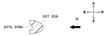
図12に示すように、本第4実施形態では、第1ガイド部207の先端部207aにおける送風方向Wの下流側の角部が鋭角になっている。このため、第1ガイド部207の先端部207aにおけるラジエータ13から近い側の角が鋭角になっている。このため、第1ガイド部207では、延設方向に交わる断面の面積は、先端部207aにおける送風方向Wの下流側で最も小さくなっている。 As shown in FIG. 12, in the fourth embodiment, the corner portion on the downstream side of the blowing direction W in the tip portion 207a of the first guide portion 207 has an acute angle. Therefore, the angle of the tip portion 207a of the first guide portion 207 on the side close to the radiator 13 is an acute angle. Therefore, in the first guide portion 207, the area of the cross section intersecting the extending direction is the smallest on the downstream side of the blowing direction W in the tip portion 207a.

一方、第2ガイド部208では、先端部208aにおける送風方向Wの上流側の角部が鋭角になっている。このため、第2ガイド部208の先端部208aにおけるラジエータ13から遠い側の角が鋭角になっている。このため、第2ガイド部208では、延設方向に交わる断面の面積は、先端部208aにおける送風方向Wの上流側で最も小さくなっている。 On the other hand, in the second guide portion 208, the corner portion on the upstream side of the blowing direction W at the tip portion 208a has an acute angle. Therefore, the angle of the tip portion 208a of the second guide portion 208 on the side far from the radiator 13 is an acute angle. Therefore, in the second guide portion 208, the area of the cross section intersecting the extending direction is the smallest on the upstream side of the blowing direction W at the tip portion 208a.

本第4実施形態によれば、第1ガイド部207の先端部207aと第2ガイド部208の先端部208aとの間隔が大きくなる。これにより、隣接するガイド部207、208の先端部207a、208aから離脱する水が重なりにくくなり、ガイド部207、208の先端部207a、208aで大きな液滴が形成されることを効果的に抑制できる。 According to the fourth embodiment, the distance between the tip portion 207a of the first guide portion 207 and the tip portion 208a of the second guide portion 208 becomes large. As a result, the water separated from the tip portions 207a and 208a of the adjacent guide portions 207 and 208 is less likely to overlap, and the formation of large droplets at the tip portions 207a and 208a of the guide portions 207 and 208 is effectively suppressed. can.

また、本第4実施形態によれば、第1ガイド部207の先端部207aとラジエータ13との距離B1よりも、第2ガイド部208の先端部208aとラジエータ13との距離B2の方が長くなる。このため、ガイド部207、208の先端部207a、208aから離脱した水がラジエータ13に付着するまでの落下距離は、第1ガイド部207よりも第2ガイド部208の方が長くなる。この結果、第1ガイド部207から散布された水がラジエータ13に付着する位置と、第2ガイド部208から散布された水がラジエータ13に付着する位置の間隔が大きくなる。これにより、ラジエータ13の背面で厚い水膜が形成されることを抑制でき、ラジエータ13の背面から後方へ吹飛ばされる水の量を低減させることができるため、ラジエータ13の冷却能力を向上させることができる。 Further, according to the fourth embodiment, the distance B2 between the tip portion 208a of the second guide portion 208 and the radiator 13 is longer than the distance B1 between the tip portion 207a of the first guide portion 207 and the radiator 13. Become. Therefore, the drop distance until the water separated from the tip portions 207a and 208a of the guide portions 207 and 208 adheres to the radiator 13 is longer in the second guide portion 208 than in the first guide portion 207. As a result, the distance between the position where the water sprayed from the first guide unit 207 adheres to the radiator 13 and the position where the water sprayed from the second guide unit 208 adheres to the radiator 13 becomes large. As a result, it is possible to suppress the formation of a thick water film on the back surface of the radiator 13, and it is possible to reduce the amount of water blown from the back surface of the radiator 13 to the rear, thereby improving the cooling capacity of the radiator 13. Can be done.

(第5実施形態)
次に、本発明の第5実施形態を図13、図14を用いて説明する。以下、上記各実施形態と異なる部分についてのみ説明する。
(Fifth Embodiment)
Next, a fifth embodiment of the present invention will be described with reference to FIGS. 13 and 14. Hereinafter, only the parts different from each of the above embodiments will be described.

図14に示すように、本第5実施形態のガイド部207、208は、上記各実施形態よりも、溝部207b、208bの深さが深くなるように形成されている。つまり、本第5実施形態では、溝部207b、208bの断面内周長さが長くなっている。溝部207b、208bの断面内周長さは、ガイド部207、208の延設方向に直交する方向における溝部207b、208bの断面内周長さである。本第5実施形態では、すべてのガイド部207、208において、溝部207b、208bの断面内周長さを同一としている。 As shown in FIG. 14, the guide portions 207 and 208 of the fifth embodiment are formed so that the depths of the groove portions 207b and 208b are deeper than those of the respective embodiments. That is, in the fifth embodiment, the inner peripheral length of the cross section of the groove portions 207b and 208b is long. The cross-sectional inner peripheral length of the groove portions 207b and 208b is the cross-sectional inner peripheral length of the groove portions 207b and 208b in the direction orthogonal to the extending direction of the guide portions 207 and 208. In the fifth embodiment, the inner peripheral lengths of the groove portions 207b and 208b are the same in all the guide portions 207 and 208.

本第5実施形態のガイド部207、208では、溝部207b、208bの断面内周長さが供給孔206の円周長さの1/2以上になるようにしている。具体的には、ガイド部207、208の延設方向に直交する方向における溝部207b、208bの断面の長さを、複数の供給孔206の配置方向における供給孔206の直径Dから算出した円周の1/2以上としている。複数の供給孔206の配置方向は、図13の左右方向である。 In the guide portions 207 and 208 of the fifth embodiment, the inner peripheral length of the cross section of the groove portions 207b and 208b is set to be ½ or more of the circumferential length of the supply hole 206. Specifically, the circumference of the cross section of the groove portions 207b and 208b in the direction orthogonal to the extending direction of the guide portions 207 and 208 is calculated from the diameter D of the supply holes 206 in the arrangement direction of the plurality of supply holes 206. It is set to 1/2 or more of. The arrangement direction of the plurality of supply holes 206 is the left-right direction in FIG.

ガイド部207、208における溝部207b、208bの断面内周長さは、供給孔206との接続部から先端部207a、208aまで均一としてもよく、供給孔206からの距離に応じて変化させてもよい。ガイド部207、208における溝部207b、208bの断面内周長さは、少なくとも供給孔206との接続部の近傍において、供給孔206の円周長さの1/2以上になっていればよい。 The inner peripheral length of the cross section of the groove portions 207b and 208b in the guide portions 207 and 208 may be uniform from the connection portion with the supply hole 206 to the tip portions 207a and 208a, or may be changed according to the distance from the supply hole 206. good. The inner peripheral length of the cross section of the groove portions 207b and 208b in the guide portions 207 and 208 may be at least ½ or more of the circumferential length of the supply hole 206 in the vicinity of the connection portion with the supply hole 206.

以上説明した本第5実施形態によれば、ガイド部207、208における溝部207b、208bの表面積が拡大して濡れ長さが長くなり、水の表面張力が作用しやすくなる。これにより、供給孔206から溝部207b、208bへ水が流出しやすくなり、溝断面と溝濡れ長さのバランスで液の落下水量を均一化する効果が高くなる。 According to the fifth embodiment described above, the surface area of the groove portions 207b and 208b in the guide portions 207 and 208 is expanded to increase the wetting length, and the surface tension of water is likely to act. As a result, water tends to flow out from the supply hole 206 to the groove portions 207b and 208b, and the effect of equalizing the amount of falling water by the balance between the groove cross section and the groove wetting length is enhanced.

(他の実施形態)
本発明は上述の実施形態に限定されることなく、本発明の趣旨を逸脱しない範囲内で、以下のように種々変形可能である。また、上記各実施形態に開示された手段は、実施可能な範囲で適宜組み合わせてもよい。
(Other embodiments)
The present invention is not limited to the above-described embodiment, and can be variously modified as follows without departing from the spirit of the present invention. In addition, the means disclosed in each of the above embodiments may be appropriately combined to the extent feasible.

(1)上記各実施形態では、本発明の水散布冷却装置を燃料電池用のラジエータ13に水を散布する散布装置20に適用した例について説明したが、本発明の水散布冷却装置を他の用途に用いてもよい。本発明の水散布冷却装置は、例えば内燃機関冷却用のラジエータに水を散布する用途に用いてもよく、あるいは冷凍サイクル装置のコンデンサに水を散布する用途に用いてもよい。 (1) In each of the above embodiments, an example in which the water spray cooling device of the present invention is applied to the spray device 20 for spraying water on the radiator 13 for a fuel cell has been described, but the water spray cooling device of the present invention is used in another method. It may be used for various purposes. The water spray cooling device of the present invention may be used, for example, for spraying water on a radiator for cooling an internal combustion engine, or may be used for spraying water on a capacitor of a refrigeration cycle device.

(2)上記第5実施形態では、すべてのガイド部207、208で溝部207b、208bの断面内周長さを同一としたが、複数のガイド部207、208で溝部207b、208bの断面内周長さを異ならせてもよい。つまり、溝部207b、208bの断面内周長さを複数段階設けてもよい。 (2) In the fifth embodiment, all the guide portions 207 and 208 have the same cross-sectional inner circumference of the groove portions 207b and 208b, but the plurality of guide portions 207 and 208 have the same cross-sectional inner circumference of the groove portions 207b and 208b. The length may be different. That is, the inner peripheral lengths of the cross sections of the groove portions 207b and 208b may be provided in a plurality of stages.

例えば、供給孔206の流入口205からの距離に応じて、供給孔206に対応するガイド部207、208の溝部207b、208bの断面内周長さを異ならせてもよい。具体的には、流入口205に近い供給孔206に設けられたガイド部207、208よりも流入口205から遠い供給孔206に設けられたガイド部207、208の方が溝部207b、208bの断面内周長さが長くなるようにしてもよい。 For example, the inner peripheral length of the cross section of the groove portions 207b and 208b of the guide portions 207 and 208 corresponding to the supply hole 206 may be different depending on the distance of the supply hole 206 from the inflow port 205. Specifically, the guide portions 207 and 208 provided in the supply hole 206 farther from the inflow port 205 than the guide portions 207 and 208 provided in the supply hole 206 near the inflow port 205 have a cross section of the groove portions 207b and 208b. The inner circumference may be lengthened.

供給孔206が流入口205から遠くなるほど、供給孔206から供給される水量が減少しやすい。このため、流入口205から遠い供給孔206に設けられたガイド部207、208で溝部207b、208bの断面内周長さを長くすることで、複数の供給孔206から散布される水量を均一化する効果が高くなる。 The farther the supply hole 206 is from the inflow port 205, the easier it is for the amount of water supplied from the supply hole 206 to decrease. Therefore, by lengthening the inner peripheral length of the cross section of the groove portions 207b and 208b at the guide portions 207 and 208 provided in the supply holes 206 far from the inflow port 205, the amount of water sprayed from the plurality of supply holes 206 is made uniform. The effect of doing is high.

また、長さが異なるガイド部207、208で溝部207b、208bの断面内周長さを異ならせてもよい。具体的には、長さが長い第2ガイド部208よりも長さが短い第1ガイド部207の方が溝部207b、208bの断面内周長さが長くなるようにしてもよい。これにより、長さが異なるガイド部207、208で溝部207b、208bの表面積を近づけることができ、濡れ長さを近づけることができる。この結果、複数の供給孔206から散布される水量を均一化する効果が高くなる。 Further, the guide portions 207 and 208 having different lengths may have different cross-sectional inner peripheral lengths of the groove portions 207b and 208b. Specifically, the inner peripheral length of the cross section of the groove portions 207b and 208b may be longer in the first guide portion 207 having a shorter length than in the second guide portion 208 having a longer length. As a result, the surface areas of the groove portions 207b and 208b can be made close to each other by the guide portions 207 and 208 having different lengths, and the wet length can be made close to each other. As a result, the effect of equalizing the amount of water sprayed from the plurality of supply holes 206 is enhanced.

(3)上記第5実施形態では、ガイド部207、208において、溝部207b、208bの深さを深くして断面内周長さを長くしたが、異なる構成によって溝部207b、208bの断面内周長さを長くしてもよい。 (3) In the fifth embodiment, in the guide portions 207 and 208, the depths of the groove portions 207b and 208b are deepened to increase the cross-sectional inner peripheral length. You may lengthen the length.

例えば、図15に示すように、溝部207b、208bを複数の溝によって構成することで、溝部207b、208bの断面内周長さを長くすることができる。 For example, as shown in FIG. 15, by forming the groove portions 207b and 208b with a plurality of grooves, the inner peripheral length of the cross section of the groove portions 207b and 208b can be lengthened.

また、溝部207b、208bの断面で構成される半円の半径を拡大することによっても、溝部207b、208bの断面内周長さを長くすることができる。 Further, by enlarging the radius of the semicircle composed of the cross sections of the grooves 207b and 208b, the inner peripheral length of the cross sections of the grooves 207b and 208b can be lengthened.

(4)上記第5実施形態では、ガイド部207、208における溝部207b、208bの表面積を拡大して濡れ長さを長くすることで、供給孔206から水が流出しやすくしたが、溝部207b、208bの濡れ性を向上させることによって供給孔206から水が流出しやすくしてもよい。 (4) In the fifth embodiment, the surface area of the groove portions 207b and 208b in the guide portions 207 and 208 is increased to increase the wet length, so that water can easily flow out from the supply hole 206. Water may easily flow out from the supply hole 206 by improving the wettability of the 208b.

例えば、図16に示すように、溝部207b、208bの内表面に表面粗さを大きくする粗化処理を施して粗化部207c、208cを形成してもよい。これにより、溝部207b、208bの濡れ性が向上して供給孔206から水が流出しやすくなり、複数の供給孔206から散布される水量を均一化する効果が高くなる。 For example, as shown in FIG. 16, the inner surfaces of the groove portions 207b and 208b may be roughened to increase the surface roughness to form the roughened portions 207c and 208c. As a result, the wettability of the grooves 207b and 208b is improved, water easily flows out from the supply holes 206, and the effect of equalizing the amount of water sprayed from the plurality of supply holes 206 is enhanced.

また、図17に示すように、溝部207b、208bの内表面に親水性処理を施して親水部207d、208dを形成してもよい。親水性処理は、例えば溝部207b、208bの内表面に親水性塗膜を設けることによって実現できる。これにより、溝部207b、208bの濡れ性が向上して供給孔206から水が流出しやすくなり、複数の供給孔206から散布される水量を均一化する効果が高くなる。 Further, as shown in FIG. 17, the inner surfaces of the groove portions 207b and 208b may be subjected to a hydrophilic treatment to form the hydrophilic portions 207d and 208d. The hydrophilic treatment can be realized, for example, by providing a hydrophilic coating film on the inner surfaces of the grooves 207b and 208b. As a result, the wettability of the grooves 207b and 208b is improved, water easily flows out from the supply holes 206, and the effect of equalizing the amount of water sprayed from the plurality of supply holes 206 is enhanced.

(5)上記各実施形態では、ガイド部207、208に設けられた溝部207b、208bの断面形状をU字状にした例について説明したが、溝部207b、208bの断面形状は任意の形状とすることができる。例えば、図18に示すように溝部207b、208bの断面形状をV字状としてもよく、溝部207b、208bの断面形状を図19に示すようにコの字状としてもよい。 (5) In each of the above embodiments, an example in which the cross-sectional shapes of the groove portions 207b and 208b provided in the guide portions 207 and 208 are U-shaped has been described, but the cross-sectional shapes of the groove portions 207b and 208b are arbitrary shapes. be able to. For example, the cross-sectional shape of the groove portions 207b and 208b may be V-shaped as shown in FIG. 18, and the cross-sectional shape of the groove portions 207b and 208b may be U-shaped as shown in FIG.

(6)上記各実施形態では、ガイド部207、208に溝部207b、208bを設けた例について説明したが、図20に示すように、ガイド部207、208に溝部207b、208bを設けることなく、親水部207d、208dを設けてもよい。親水部207d、208dは、供給孔206からガイド部207、208の先端部207a、208aに至るまで設ければよい。 (6) In each of the above embodiments, an example in which the groove portions 207b and 208b are provided in the guide portions 207 and 208 has been described, but as shown in FIG. 20, the guide portions 207 and 208 are not provided with the groove portions 207b and 208b. Hydrophilic portions 207d and 208d may be provided. The hydrophilic portions 207d and 208d may be provided from the supply hole 206 to the tip portions 207a and 208a of the guide portions 207 and 208.

親水部207d、208dを設けた部分では、水が濡れやすくなるため、供給孔206から供給された水が大きな液滴を形成する前に重力によってガイド部207、208を伝って下方に移動可能となる。 In the portion where the hydrophilic portions 207d and 208d are provided, the water becomes easy to get wet, so that the water supplied from the supply hole 206 can move downward through the guide portions 207 and 208 by gravity before forming large droplets. Become.

(7)上記各実施形態では、ガイド部207、208の延設方向に交わるガイド部207、208の断面形状を長方形としたが、これに限らず、ガイド部207、208の断面形状を送風方向Wの上流側に向かって寸法が小さくなるようにしてもよい。送風方向Wの上流側に向かって寸法が小さくなるガイド部207、208の断面形状は、例えば図21、図22、図23に示す形状とすることができる。 (7) In each of the above embodiments, the cross-sectional shape of the guide portions 207 and 208 intersecting the extending direction of the guide portions 207 and 208 is rectangular, but the cross-sectional shape of the guide portions 207 and 208 is not limited to this and the cross-sectional shape of the guide portions 207 and 208 is the blowing direction. The dimension may be reduced toward the upstream side of W. The cross-sectional shapes of the guide portions 207 and 208 whose dimensions decrease toward the upstream side in the blowing direction W can be, for example, the shapes shown in FIGS. 21, 22, and 23.

このように、ガイド部207、208の断面形状を送風方向Wの上流側に向かって寸法が小さくなるようにすることで、ガイド部207、208の通風抵抗を小さくすることができる。 In this way, by making the cross-sectional shape of the guide portions 207 and 208 smaller in dimension toward the upstream side of the ventilation direction W, the ventilation resistance of the guide portions 207 and 208 can be reduced.

(8)上記各実施形態では、ガイド部207、208における送風方向Wの下流側に溝部207b、208bを設けたが、溝部207b、208bを設ける位置は、ガイド部207、208における送風方向Wの上流側でもよく、あるいはガイド部207、208における送風方向Wの上流側と下流側の間でもよい。 (8) In each of the above embodiments, the groove portions 207b and 208b are provided on the downstream side of the ventilation direction W in the guide portions 207 and 208, but the position where the groove portions 207b and 208b are provided is the position of the ventilation direction W in the guide portions 207 and 208. It may be on the upstream side, or may be between the upstream side and the downstream side of the ventilation direction W in the guide portions 207 and 208.

(9)上記各実施形態では、水供給管201、202のガイド部207、208を重力方向に平行となるように設けたが、これに限らず、ガイド部207、208は重力方向に対して傾斜していてもよい。複数のガイド部207、208の重力方向に対する角度は同一でもよく、異なっていてもよい。 (9) In each of the above embodiments, the guide portions 207 and 208 of the water supply pipes 201 and 202 are provided so as to be parallel to the gravity direction, but the present invention is not limited to this, and the guide portions 207 and 208 are provided with respect to the gravity direction. It may be tilted. The angles of the plurality of guide portions 207 and 208 with respect to the gravitational direction may be the same or may be different.

(10)上記各実施形態では、散布装置20に2本の水供給管201、202を設けた例について説明したが、これに限らず、散布装置20に1本又は3本以上の水供給管を設けてもよい。 (10) In each of the above embodiments, an example in which two water supply pipes 201 and 202 are provided in the spraying device 20 has been described, but the present invention is not limited to this, and one or three or more water supply pipes are provided in the spraying device 20. May be provided.

(11)上記各実施形態では、散布装置20に長さが異なる2種類のガイド部207、208を設けたが、同一の長さの1種類のガイド部を設けてもよく、あるいは長さが異なる3種類以上のガイド部を設けてもよい。 (11) In each of the above embodiments, the spraying device 20 is provided with two types of guide portions 207 and 208 having different lengths, but one type of guide portions having the same length may be provided, or the length may be different. Three or more different types of guide portions may be provided.

(12)上記各実施形態では、複数の供給孔206のすべてにガイド部207、208を設けたが、これに限らず、少なくとも一部の供給孔206にガイド部207、208が設けられていればよい。つまり、ガイド部207、208が設けられていない供給孔206が存在してもよい。 (12) In each of the above embodiments, the guide portions 207 and 208 are provided in all of the plurality of supply holes 206, but the present invention is not limited to this, and the guide portions 207 and 208 may be provided in at least a part of the supply holes 206. Just do it. That is, there may be a supply hole 206 in which the guide portions 207 and 208 are not provided.

13 ラジエータ(熱交換器)
20 散布装置
206 供給孔
207 第1ガイド部
207a 先端部
207b 溝部
208 第2ガイド部
208a 先端部
208b 溝部
13 Radiator (heat exchanger)
20 Spreading device 206 Supply hole 207 1st guide part 207a Tip part 207b Groove part 208 2nd guide part 208a Tip part 208b Groove part

Claims (11)

予め定められた送風方向へ流れる空気と内部を流通する熱媒体との間で熱交換を行う熱交換器(13)に対し、前記送風方向の上流側から水を散布する散布装置(20)を備え、
前記散布装置は、前記熱交換器に散布される水を供給する供給孔(206)と、前記供給孔から重力方向下側に延びるように形成され、前記供給孔から供給される水を誘導するガイド部(207、208)とを含んでおり、
前記供給孔は複数設けられており、前記ガイド部は複数の前記供給孔のそれぞれに対応して設けられており、
隣接する前記ガイド部は、それぞれ長さが異なっている水散布冷却装置。
For the heat exchanger (13) that exchanges heat between the air flowing in the predetermined blowing direction and the heat medium flowing inside, the spraying device (20) that sprays water from the upstream side in the blowing direction is provided. Prepare,
The spraying device is formed to have a supply hole (206) for supplying water to be sprayed to the heat exchanger and to extend downward in the direction of gravity from the supply hole to guide the water supplied from the supply hole. Includes guides (207, 208)
A plurality of the supply holes are provided, and the guide portion is provided corresponding to each of the plurality of supply holes .
The adjacent guide portions are water spray cooling devices having different lengths .
前記複数のガイド部は互いに交わらないように配置されている請求項1に記載の水散布冷却装置。 The water spray cooling device according to claim 1, wherein the plurality of guide portions are arranged so as not to intersect each other. 前記ガイド部の表面には親水性処理が施されている請求項1または2に記載の水散布冷却装置。 The water spray cooling device according to claim 1 or 2 , wherein the surface of the guide portion is subjected to a hydrophilic treatment. 前記ガイド部には、前記供給孔から供給された水を誘導する溝部(207b、208b)が形成されている請求項1または2のいずれか1つに記載の水散布冷却装置。 The water spray cooling device according to any one of claims 1 or 2 , wherein a groove portion (207b, 208b) for guiding water supplied from the supply hole is formed in the guide portion. 前記溝部は前記供給孔と接続されている請求項に記載の水散布冷却装置。 The water spray cooling device according to claim 4 , wherein the groove portion is connected to the supply hole. 前記ガイド部の延設方向に直交する断面における前記溝部の内周の長さは、複数の前記供給孔の配置方向における前記供給孔の直径から算出した円周の1/2以上である請求項4または5に記載の水散布冷却装置。 Claimed that the length of the inner circumference of the groove portion in the cross section orthogonal to the extending direction of the guide portion is ½ or more of the circumference calculated from the diameters of the supply holes in the arrangement direction of the plurality of supply holes. 4. The water spray cooling device according to 4. 前記溝部の表面は、表面粗さを大きくする粗面化処理が施されている請求項4ないし6のいずれか1つに記載の水散布冷却装置。 The water spray cooling device according to any one of claims 4 to 6 , wherein the surface of the groove portion is subjected to a roughening treatment for increasing the surface roughness. 前記溝部の表面に親水性処理が施されている請求項4ないし7のいずれか1つに記載の水散布冷却装置。 The water spray cooling device according to any one of claims 4 to 7 , wherein the surface of the groove portion is subjected to a hydrophilic treatment. 前記溝部は、前記ガイド部の延設方向に直交する断面の形状がU字形状、V字状又はコの字状のいずれかである請求項4ないし8のいずれか1つに記載の水散布冷却装置。 The water according to any one of claims 4 to 8 , wherein the groove portion has a cross section orthogonal to the extending direction of the guide portion having a U-shape, a V-shape, or a U-shape. Spray cooling device. 前記溝部は前記ガイド部の先端部(207a、208a)まで形成されており、
前記ガイド部の先端部は、前記溝部が設けられている部位が鋭角になっている請求項4ないし9のいずれか1つに記載の水散布冷却装置。
The groove portion is formed up to the tip portions (207a, 208a) of the guide portion.
The water spray cooling device according to any one of claims 4 to 9 , wherein the tip portion of the guide portion has an acute angle at a portion where the groove portion is provided .
前記隣接するガイド部には、第1ガイド部(207)と、前記第1ガイド部より長い第2ガイド部(208)が含まれており、
前記第1ガイド部の先端部(207a)は、前記送風方向の下流側の角部が鋭角になっており、前記第2ガイド部の先端部(208a)は、前記送風方向の上流側の角部が鋭角になっている請求項1ないしのいずれか1つに記載の水散布冷却装置。
The adjacent guide portion includes a first guide portion (207) and a second guide portion (208) longer than the first guide portion.
The tip portion (207a) of the first guide portion has an acute angle on the downstream side corner in the ventilation direction, and the tip portion (208a) of the second guide portion has an acute angle on the upstream side in the ventilation direction. The water spray cooling device according to any one of claims 1 to 9 , wherein the portion has an acute angle .
JP2019163191A 2018-09-28 2019-09-06 Water spray cooling device Active JP7015284B2 (en)

Priority Applications (2)

Application Number Priority Date Filing Date Title
PCT/JP2019/036874 WO2020066864A1 (en) 2018-09-28 2019-09-20 Water-spraying cooling device
US17/209,448 US20210207891A1 (en) 2018-09-28 2021-03-23 Water-spraying cooling device

Applications Claiming Priority (2)

Application Number Priority Date Filing Date Title
JP2018183607 2018-09-28

Publications (3)

Publication Number Publication Date
JP2020056564A JP2020056564A (en) 2020-04-09
JP2020056564A5 JP2020056564A5 (en) 2020-12-10
JP7015284B2 true JP7015284B2 (en) 2022-02-02

Family

ID=70106971

Family Applications (1)

Application Number Title Priority Date Filing Date
JP2019163191A Active JP7015284B2 (en) 2018-09-28 2019-09-06 Water spray cooling device

Country Status (2)

Country Link
US (1) US20210207891A1 (en)
JP (1) JP7015284B2 (en)

Families Citing this family (3)

* Cited by examiner, † Cited by third party
Publication number Priority date Publication date Assignee Title
JP7015284B2 (en) * 2018-09-28 2022-02-02 株式会社デンソー Water spray cooling device
JP2022022624A (en) * 2020-06-30 2022-02-07 株式会社デンソー Water spraying cooling device
DE102022114018A1 (en) * 2022-06-02 2023-12-07 Man Truck & Bus Se Cooling device, control device and cooling system for cooling a cooling fluid by means of air and evaporative cooling

Citations (5)

* Cited by examiner, † Cited by third party
Publication number Priority date Publication date Assignee Title
JP2002301492A (en) 2001-04-09 2002-10-15 Fujikin Inc Water cleaning apparatus and water tank using the same
JP2002372385A (en) 2001-04-11 2002-12-26 Denso Corp Heat exchanging system
JP2006322642A (en) 2005-05-18 2006-11-30 Toyo Shoji Kk Air conditioner power saving device
JP2007205677A (en) 2006-02-03 2007-08-16 Daikin Ind Ltd Auxiliary cooling device of outdoor unit
JP2010243050A (en) 2009-04-06 2010-10-28 Kawasaki Heavy Ind Ltd Spraying tube device and heat exchanger using this

Family Cites Families (48)

* Cited by examiner, † Cited by third party
Publication number Priority date Publication date Assignee Title
US2185033A (en) * 1938-06-02 1939-12-26 Waukesha Motor Co Refrigerating apparatus
US2278242A (en) * 1940-12-28 1942-03-31 Gen Electric Evaporative cooler
GB599400A (en) * 1941-04-30 1948-03-11 Delas Condenseurs Improvements in apparatus for bringing a gas into contact with a liquid
DE808846C (en) * 1948-01-10 1951-07-19 Der Niederlaendische Staat Ver Sprinkler
US3290025A (en) * 1965-11-19 1966-12-06 Baltimore Aircoil Co Inc Trough system for evaporative heat exchangers
US3659623A (en) * 1969-12-02 1972-05-02 Baltimore Aircoil Co Inc Water supply system
CH558925A (en) * 1974-01-17 1975-02-14 Energiagazdalkodasi Intezet DEVICE FOR HEAT AND MATERIAL TRANSFER BETWEEN LIQUIDS AND GASES.
US3926000A (en) * 1974-06-24 1975-12-16 Carlie D Scofield Automotive air conditioner and method of operating the same
US4159291A (en) * 1977-08-16 1979-06-26 Union Carbide Corporation Outlet means for vapor-liquid contacting tray
CA1120396A (en) * 1979-01-09 1982-03-23 Rolf P.C. Manteufel Device for feeding liquids into material and heat exchanger columns
JPS5838677B2 (en) * 1980-09-20 1983-08-24 住友精密工業株式会社 Open rack type vaporizer water sprinkler system
DE3141930C2 (en) * 1981-10-22 1986-07-10 Julius Montz Gmbh, 4010 Hilden Distribution tray for an exchange column
CH658198A5 (en) * 1983-01-04 1986-10-31 Sulzer Ag LIQUID DISTRIBUTOR IN A SUBSTANCE AND HEAT EXCHANGE COLUMN.
US4516406A (en) * 1983-02-22 1985-05-14 Gentry And Green Enterprises Cooling system for motor vehicles
US4476069A (en) * 1983-02-23 1984-10-09 The Dow Chemical Company Liquid distributing apparatus for a liquid-vapor contact column
US4776989A (en) * 1983-09-19 1988-10-11 The Dow Chemical Company Method and apparatus for liquid feed to liqiud distributors in fluid-liquid contacting towers
US4494384A (en) * 1983-11-21 1985-01-22 Judy A. Lott Apparatus for enhancing the performance of a vehicle air conditioning system
CH671165A5 (en) * 1987-03-02 1989-08-15 Sulzer Ag
CH674895A5 (en) * 1988-03-22 1990-07-31 Kuehni Ag
US4994210A (en) * 1990-03-01 1991-02-19 Koch Engineering Company, Inc. High efficiency distributor for gas-liquid contact column and method of preparation and use
JPH0712427A (en) * 1993-04-27 1995-01-17 Daikin Ind Ltd Heat transfer tube for absorption refrigerating machine and manufacture thereof as well as heat exchanger for absorption refrigerating machine
US5444991A (en) * 1993-05-03 1995-08-29 Cox; William L. Engine cooling apparatus
JP3575071B2 (en) * 1994-08-11 2004-10-06 ダイキン工業株式会社 Heat exchanger for absorption refrigerator
US5884658A (en) * 1996-09-05 1999-03-23 Cameron; Gordon M. Liquid distributor for a packed tower
DE29701830U1 (en) * 1997-02-03 1997-06-05 Raschig Ag Dispersion device for a liquid distributor
JP3572869B2 (en) * 1997-05-29 2004-10-06 ダイキン工業株式会社 Sprayer for absorption refrigerator
US5919405A (en) * 1997-10-23 1999-07-06 Monsanto Company Fluid distribution system for an absorption tower
DE59911838D1 (en) * 1998-11-30 2005-05-04 Sulzer Chemtech Ag Winterthur Liquid distributor for packed columns
ES2237070T3 (en) * 1998-11-30 2005-07-16 Sulzer Chemtech Ag CONTRACTOR COLUMN WITH LIQUID DISTRIBUTOR.
CA2338215C (en) * 2000-05-08 2004-09-14 Sulzer Chemtech Ag Guide member for a liquid jet to be deflected
US6830099B2 (en) * 2002-12-13 2004-12-14 American Standard International Inc. Falling film evaporator having an improved two-phase distribution system
US8596556B2 (en) * 2005-02-22 2013-12-03 Vehicle Enhancement Labs Radiator and air cooler mister
WO2009089503A2 (en) * 2008-01-11 2009-07-16 Johnson Controls Technology Company Vapor compression system
KR101203361B1 (en) * 2010-06-03 2012-11-20 (주)써스텍 Counter flow type of cooling tower having improved cooling efficiency
JP6053389B2 (en) * 2012-08-10 2016-12-27 三菱重工業株式会社 Ship equipped with liquefied gas vaporizer and liquefied gas vaporizer
US9089787B2 (en) * 2012-12-14 2015-07-28 Koch-Glitsch, Lp Distributor in mass transfer column and method of use
DE102014105008B4 (en) * 2014-04-08 2017-05-18 Technische Universität Berlin Liquid distributor and arrangement
FR3038038B1 (en) * 2015-06-24 2017-07-21 Commissariat Energie Atomique DEVICE FOR DISPENSING FILM FALLING ON A PLATE EXCHANGER COMPRISING FIRST AND SECOND DISTRIBUTION STAGES
JP7010702B2 (en) * 2015-12-24 2022-01-26 日本電気株式会社 Heat exchanger and cooling tower
JP2019045000A (en) * 2017-08-30 2019-03-22 株式会社デンソー Water spray cooling device
JP2019044999A (en) * 2017-08-30 2019-03-22 株式会社デンソー Water spray cooling device
JP2019043385A (en) * 2017-09-04 2019-03-22 株式会社デンソー Water spray cooling device
JP7015284B2 (en) * 2018-09-28 2022-02-02 株式会社デンソー Water spray cooling device
WO2020066864A1 (en) * 2018-09-28 2020-04-02 株式会社デンソー Water-spraying cooling device
JP2022022624A (en) * 2020-06-30 2022-02-07 株式会社デンソー Water spraying cooling device
DE102020208710A1 (en) * 2020-07-13 2022-01-13 Mahle International Gmbh Heat exchanger, fuel cell arrangement and method
JP2022024908A (en) * 2020-07-28 2022-02-09 トヨタ自動車株式会社 Structure for preventing damage of water supply pipe in freezing
JP2022178998A (en) * 2021-05-21 2022-12-02 株式会社デンソー Water sprinkle cooling device

Patent Citations (5)

* Cited by examiner, † Cited by third party
Publication number Priority date Publication date Assignee Title
JP2002301492A (en) 2001-04-09 2002-10-15 Fujikin Inc Water cleaning apparatus and water tank using the same
JP2002372385A (en) 2001-04-11 2002-12-26 Denso Corp Heat exchanging system
JP2006322642A (en) 2005-05-18 2006-11-30 Toyo Shoji Kk Air conditioner power saving device
JP2007205677A (en) 2006-02-03 2007-08-16 Daikin Ind Ltd Auxiliary cooling device of outdoor unit
JP2010243050A (en) 2009-04-06 2010-10-28 Kawasaki Heavy Ind Ltd Spraying tube device and heat exchanger using this

Also Published As

Publication number Publication date
JP2020056564A (en) 2020-04-09
US20210207891A1 (en) 2021-07-08

Similar Documents

Publication Publication Date Title
JP7015284B2 (en) Water spray cooling device
JP2002372385A (en) Heat exchanging system
US10707505B2 (en) Fuel cell system
JP4269060B2 (en) Heat removal method and heat removal apparatus
JP6870621B2 (en) Fuel cell system
JP4939786B2 (en) Fuel cell and fuel cell system
JP6569522B2 (en) Heat exchanger
JP6638613B2 (en) Fuel cell system
JP2008269844A (en) Fuel cell system
WO2020066864A1 (en) Water-spraying cooling device
WO2022004157A1 (en) Water spray cooling device
KR20150093455A (en) Air cooled heat exchanger and closed circuit cooling tower using a low air pressure drop haet exchange tube
JP2022178998A (en) Water sprinkle cooling device
JP6972633B2 (en) Fuel cell system
JP7131493B2 (en) fuel cell system
KR100654330B1 (en) Evaporative humidifier for fuel cell system
JP2019051478A (en) Liquid recovery device
JP2019044999A (en) Water spray cooling device
KR102595244B1 (en) Humidification and cooling device for fuel cell
JP2019045000A (en) Water spray cooling device
JP6784247B2 (en) Fuel cell system
JP7077633B2 (en) Heat exchanger
JP2019121578A (en) Fuel cell system
JP2008305627A (en) Fuel cell stack system
JP6919511B2 (en) Evaporator

Legal Events

Date Code Title Description
A521 Request for written amendment filed

Free format text: JAPANESE INTERMEDIATE CODE: A821

Effective date: 20190909

A521 Request for written amendment filed

Free format text: JAPANESE INTERMEDIATE CODE: A523

Effective date: 20201028

A621 Written request for application examination

Free format text: JAPANESE INTERMEDIATE CODE: A621

Effective date: 20201110

A131 Notification of reasons for refusal

Free format text: JAPANESE INTERMEDIATE CODE: A131

Effective date: 20210907

A521 Request for written amendment filed

Free format text: JAPANESE INTERMEDIATE CODE: A523

Effective date: 20211005

TRDD Decision of grant or rejection written
A01 Written decision to grant a patent or to grant a registration (utility model)

Free format text: JAPANESE INTERMEDIATE CODE: A01

Effective date: 20211228

A61 First payment of annual fees (during grant procedure)

Free format text: JAPANESE INTERMEDIATE CODE: A61

Effective date: 20220121