JP7002002B2 - Tightening hook mounting structure - Google Patents
Tightening hook mounting structure Download PDFInfo
- Publication number
- JP7002002B2 JP7002002B2 JP2018017440A JP2018017440A JP7002002B2 JP 7002002 B2 JP7002002 B2 JP 7002002B2 JP 2018017440 A JP2018017440 A JP 2018017440A JP 2018017440 A JP2018017440 A JP 2018017440A JP 7002002 B2 JP7002002 B2 JP 7002002B2
- Authority
- JP
- Japan
- Prior art keywords
- hook
- front frame
- joined
- tightening
- mounting structure
- Prior art date
- Legal status (The legal status is an assumption and is not a legal conclusion. Google has not performed a legal analysis and makes no representation as to the accuracy of the status listed.)
- Active
Links
Images


Landscapes
- Body Structure For Vehicles (AREA)
Description
本発明は、剛性の向上を図り得る緊締フックの取付構造に関する。 The present invention relates to a mounting structure for a tightening hook that can improve rigidity.
1本の線状部材をほぼU字状に屈曲させて形成したトーイングフック(牽引用フック)の互いに対向する中間部に、複数の突起を幅方向に設けたL字形補強板の一面を架設し、該補強板にて前記トーイングフックの対向する端部間の距離を一定に保持し、前記トーイングフックの対向する端部を車両の車幅方向に沿って配設されるクロスメンバの前後両側面にそれぞれ固着するとともに、前記補強板の他面を前記クロスメンバの底面に固着したトーイングフックの取付構造が知られている(特許文献1参照)。 One side of an L-shaped reinforcing plate with a plurality of protrusions in the width direction is erected at the intermediate portion of the towing hook (towing hook) formed by bending one linear member into a substantially U-shape so as to face each other. The reinforcing plate keeps the distance between the facing ends of the towing hook constant, and the facing ends of the towing hook are arranged on both front and rear surfaces of the cross member along the vehicle width direction of the vehicle. There is known a mounting structure of a towing hook in which the other surface of the reinforcing plate is fixed to the bottom surface of the cross member while being fixed to each of the above (see Patent Document 1).
上記先行技術は、線状部材をU字状に屈曲させて形成したトーイングフックの対向する線状部材の端部を、車両の幅方向に配設されるクロスメンバの前後両側面に固着している。トーイングフックの対向する中間部にはL字状の補強板の一面を架設し、補強板の他面をクロスメンバの底面に固着している。溶接個所がトーイングフックを構成する線状部材に沿って同方向に設けられているので、一定方向に対しては、剛性が保てるが他の方向に対しては十分な剛性を保つことは難しい。また、補強板によってトーイングフックの対向する端部間を接合しているが、補強板の厚さが必要で、重量が重くなる課題がある。 In the above prior art, the ends of the facing linear members of the towing hook formed by bending the linear member in a U shape are fixed to both front and rear surfaces of the cross member arranged in the width direction of the vehicle. There is. One side of the L-shaped reinforcing plate is erected at the opposite intermediate portion of the towing hook, and the other side of the reinforcing plate is fixed to the bottom surface of the cross member. Since the welded portion is provided in the same direction along the linear member constituting the towing hook, the rigidity can be maintained in one direction, but it is difficult to maintain sufficient rigidity in the other direction. Further, although the reinforcing plates are used to join the facing ends of the towing hooks, there is a problem that the reinforcing plate needs to be thick and the weight becomes heavy.
本発明は、上記課題を解決し、十分な剛性を確保することができる緊締フックの取付構造を提供することを目的とする。 An object of the present invention is to solve the above-mentioned problems and to provide a mounting structure for a tightening hook capable of ensuring sufficient rigidity.
本発明は、上記課題を解決するため、車両の車幅方向中央部よりも外方に、車両の前後方向に延びるフロントフレームが設けられ、このフロントフレームに接合されて車幅方向に延びる横方向部材を設けた車体に取り付けられる緊締フックの取付構造において、棒状部材をU字状に折り曲げてフック部を形成した緊締フックの上方に延びる一端部が前記フロントフレームと横方向部材の交差隅部に延出されて、溶接により前記両部材に接合されて取り付けられ、前記緊締フックの上方に延びる他端部が途中から車幅方向に折り曲げられており、該折り曲げ部が前記フロントフレームに溶接により接合されていることにある。 In order to solve the above problems, the present invention is provided with a front frame extending in the front-rear direction of the vehicle outside the central portion in the vehicle width direction of the vehicle, and is joined to the front frame in the lateral direction extending in the vehicle width direction. In the mounting structure of the tightening hook attached to the vehicle body provided with the member, one end extending upward of the tightening hook formed by bending the rod-shaped member into a U shape is located at the intersecting corner of the front frame and the lateral member. It is extended and joined to both members by welding and attached, and the other end extending upward of the tightening hook is bent in the vehicle width direction from the middle, and the bent portion is joined to the front frame by welding. It is to be done.
緊締フックの上方に延びる一端部が前記フロントフレームと横方向部材の交差隅部に延出されて、溶接により前記両部材に接合されて取り付けられており、緊締フックの上方に延びる他端部が途中から車幅方向に折り曲げられており、該折り曲げ部が前記フロントフレームに溶接により接合されているので、荷重が各方向に伝達され、分散されるので、大きな荷重に対応することができる。 One end extending upward of the tightening hook extends to the intersecting corner of the front frame and the lateral member, and is joined and attached to both members by welding, and the other end extending upward of the tightening hook is attached. Since it is bent in the vehicle width direction from the middle and the bent portion is joined to the front frame by welding, the load is transmitted and distributed in each direction, so that it is possible to cope with a large load.
以下、本発明の実施の形態を、図面を参照しながら詳細に説明する。
図1はトラック等の自動車の左側車体1下部に設けられた緊締フック2を示したものである。自動車の車体1には、車両の車幅方向中央部よりも外方に、左右の前後方向に一対のフロントフレーム(サイドメンバとも言う)3が設けられ、このフロントフレーム3相互間には車幅方向に横方向部材としてのクロスメンバ4が車体1の前後方向に所定間隔で複数、設けられている。
Hereinafter, embodiments of the present invention will be described in detail with reference to the drawings.
FIG. 1 shows a
前記フロントフレーム3は、図2に示すように、鋼板を折り曲げてコ字状に形成し、このコ字状部の開口部を上面にして両側側壁面31の上端部に外側に向けてフランジ31aを設けたものである。前記フロントフレーム3は、これらフランジ31aを介してフロアパネル5の底面51にスポット溶接等により接合されている。前記緊締フック2が設けられる個所の車体1の前記フロントフレーム3の外側外方には、横方向部材としてのフロントフレームサイドメンバ6およびフレームサイドリアメンバ7が車幅方向に沿って前記フロントフレーム3とサイドシル部8との間のフロアパネル5の底面51に設けられている。前記フロントフレームサイドメンバ6は、図3および図4に示すように、鋼板を折り曲げてコ字状に形成し、このコ字状部の開口部を上面にして両側壁面部61の上端部に外側に向けてフランジ61aを設けたものである。このフロントフレームサイドメンバ6は、これらフランジ61aを介してフロアパネル5の底面51にスポット溶接等により接合されている。このフロントフレームサイドメンバ6の後方には、同様のコ字形形状をした前記フレームサイドリアメンバ7が車幅方向に沿って前記フロントフレーム3とサイドシル部8との間のフロアパネル5の底面51に設けられている。
As shown in FIG. 2, the
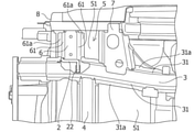
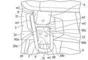
図5および図6は、前記フロントフレーム3に設けられた緊締フック2の取付部分を拡大して示したもので、前記フロントフレームサイドメンバ6が設けられる部分の前記フロントフレーム3に前記緊締フック2が取り付けられている。前記緊締フック2は、1本の線状部材、例えば丸棒等の棒状の部材20を略U字状に折り曲げてU字状フック部21が形成されている。前記緊締フック2は、フック部21の上方に同一垂直平面上に一定の間隔で延びる前方一端部の縦部分と後方他端部の縦部分としての棒状部20a,20bが設けられている。後方他端部の縦部分としての棒状部20bを略半分程度の途中から平面と交叉する方向の垂直面に沿って車幅方向、すなわち水平方向に直角に折り曲げて折り曲げ部22が形成されている。前記緊締フック2の棒状部20a,20b相互には、棒状部20a,20b相互を連結した連結部材9が掛け渡されている。この連結部材9は四角形をした板状の補強プレート90で、補強プレート90の裏側(車体内方側)の両側部を前記棒状部20a,20bの一側に線溶接w1により接合されている。補強プレート90の表側(車体外側)の前方側側部は、前記棒状部20a一側に線溶接w1により接合されており、補強プレート90の表側(車体外側)の後方側側部は、前記棒状部20bには溶接していない。
前記連結部材9のプレート90の上辺部90aは、折り曲げ部22よりも上方まで延出されていて、上辺部90aの縁部90bをフロントフレーム3の外側側壁面31に線溶接w2により接合されている。
5 and 6 show an enlarged view of the mounting portion of the
The
前記緊締フック2は、前方縦方向に設けられる一方の棒状部20aをフロントフレーム3とフロントフレームサイドメンバ6の接合される交差隅部Rに配置され、この交差隅部Rのフロントフレーム3とフロントフレームサイドメンバ6の両側壁面にそれぞれ線溶接w3により接合されている。また、前記緊締フック2は、他方の棒状部20bの折り曲げ部22をフロントフレーム3の底面32に線溶接w4により接合されている。前記連結部材9のプレート90は、上辺部90aの縁部90bから前記棒状部20bの折り曲げ部22がある側の角部90cにかけて線溶接w2、w5により接合されている。
In the
上記実施の形態によれば、緊締フック2は、一方の棒状部20aをフロントフレーム3とフロントフレームサイドメンバ6の接合される交差隅部Rに配置され、この交差隅部Rのフロントフレーム3とフロントフレームサイドメンバ6の両側壁面にそれぞれ線溶接w3により接合されている。また、前記緊締フック2は、他方の棒状部20bの折り曲げ部22をフロントフレーム3の底面32に線溶接w4により接合されている。棒状部20a,20b相互を連結した連結部材9のプレート90の上端部90aは、前記棒状部20bの折り曲げ部22がある側の縁部90bから角部90cにかけて線溶接w2、w5により接合されている。こうして、緊締フック2に加わる応力は、一方の棒状部20aから交差隅部Rのフロントフレーム3とフロントフレームサイドメンバ6の両側壁面を通して、フロントフレーム3とフロントフレームサイドメンバ6に伝わり、車体1の前後方向と車幅方向に分散されて吸収される。一方、他方の棒状部20bに加わる応力は棒状部20bの折り曲げ部22を通してフロントフレーム3の底面32に伝わり、フロントフレーム3の底面32から上下方向および前後方向に分散されて吸収される。このように、荷重が各方向に分散されて伝達されるので、大きな荷重に対応することができる。
According to the above embodiment, in the
前記フロントフレーム3に接合されて車幅方向に延びる横方向部材としてのクロスメンバ4は、前記フック部21の後方他端部としての棒状部20bの上端部を車幅方向に折り曲げた折り曲げ部22と側面視で一致するように設けられているので、クロスメンバ4を通して荷重が各方向に伝達され分散されるので、大きな荷重に対応することができる。
The
また、前記緊締フックのフック部21の前方一端部としての棒状部20aと、後方他端部としての棒状部20bに連結部材9を掛け渡して設けている。この連結部材9の両端部を線溶接w1により前記フック部21の前方一端部としての棒状部20aと、後方他端部としての棒状部20bに接合して設け、前記連結部材9の前記前方一端部を線溶接w1により前記フロントフレーム3の側壁面31に接合したので、車両前後方向の荷重に対してせん断方向で荷重を受けるので、大きな荷重に対応することができる。
Further, the connecting
前記連結部材9の上辺部90aの縁部90bを前記フロントフレーム3に線溶接w2により接合し、かつ前記連結部材9の上辺部90aの後方角部90cを線溶接w5により前記フロントフレーム3の側壁面31に接合したので、溶接範囲が増えて強度が増し、向きも変わるので、いろいろな向きの荷重に対応できる。この連結部材9は四角形をした板状の補強プレート90で、補強プレート90の裏側(車体内方側)の両側部を前記棒状部20a,20bの一側に線溶接w1により接合されている。補強プレート90の表側(車体外側)の前方側側部は、前記棒状部20a一側に線溶接w1により接合されており、補強プレート90の表側(車体外側)の後方側側部は、前記棒状部20bには溶接していない。これは、前記緊締フック2が、他方の棒状部20bの折り曲げ部22をフロントフレーム3の底面32に線溶接w4により接合されており、さらに棒状部20a,20b相互を連結した連結部材9のプレート90の上端部90aは、前記棒状部20bの折り曲げ部22がある側の縁部90bから角部90cにかけて線溶接w2、w5により接合されているので、十分な剛性が確保されるからである。
The
なお、前記連結部材9の上辺部90aの後方角部90cに線溶接w5を施したが、前方角部に対しても線溶接を施すこともできる。また、上記実施の形態では前記連結部材9の後方外側に対しては、線溶接を行っていないが、この部分に対しても線溶接を行うことも可能である。
Although the wire welding w5 is applied to the
本発明は、上記実施の形態のみに限定されるものではなく、上記実施の形態では緊締フック2は、車体1の前方左側のフロントフレーム3に対して適用したが、車体1の右側に適用することもできる。また、車体1の後方側のフレームに対して適用することもできる。また、緊締フック2は、車体の前後に適用することもできる。そして、緊締フック2には丸棒を用いたが、角棒でも、板状のものに対しても適用することができる。等、その他、本発明の技術的範囲を変更することなく、適宜変更して実施しうることは言うまでもない。
The present invention is not limited to the above embodiment, and in the above embodiment, the tightening
1 車体
2 緊締フック
20 棒状の部材
20a,20b 棒状部
21 U字状フック部(フック部)
22 折り曲げ部
3 フロントフレーム(サイドメンバ)
31 側壁面
31a フランジ
4 クロスメンバ
5 フロアパネル
51 底面
6 フロントフレームサイドメンバ
61 壁面部
7 フレームサイドリアメンバ
8 サイドシル部
9 連結部材
90 補強プレート
90a 上辺部
90b 縁部
1
22
31
Claims (5)
Priority Applications (1)
| Application Number | Priority Date | Filing Date | Title |
|---|---|---|---|
| JP2018017440A JP7002002B2 (en) | 2018-02-02 | 2018-02-02 | Tightening hook mounting structure |
Applications Claiming Priority (1)
| Application Number | Priority Date | Filing Date | Title |
|---|---|---|---|
| JP2018017440A JP7002002B2 (en) | 2018-02-02 | 2018-02-02 | Tightening hook mounting structure |
Publications (2)
| Publication Number | Publication Date |
|---|---|
| JP2019131143A JP2019131143A (en) | 2019-08-08 |
| JP7002002B2 true JP7002002B2 (en) | 2022-02-04 |
Family
ID=67545494
Family Applications (1)
| Application Number | Title | Priority Date | Filing Date |
|---|---|---|---|
| JP2018017440A Active JP7002002B2 (en) | 2018-02-02 | 2018-02-02 | Tightening hook mounting structure |
Country Status (1)
| Country | Link |
|---|---|
| JP (1) | JP7002002B2 (en) |
Citations (3)
| Publication number | Priority date | Publication date | Assignee | Title |
|---|---|---|---|---|
| JP2006035920A (en) | 2004-07-23 | 2006-02-09 | Suzuki Motor Corp | Hook mounting structure |
| JP2013035461A (en) | 2011-08-09 | 2013-02-21 | Mitsubishi Motors Corp | Vehicle front structure |
| US8714592B1 (en) | 2013-09-12 | 2014-05-06 | Hendrick Motorsports Performance Group, LLC | System for securing a vehicle during transport against movement under forces from multiple directions |
Family Cites Families (5)
| Publication number | Priority date | Publication date | Assignee | Title |
|---|---|---|---|---|
| JPS5795263A (en) * | 1980-12-01 | 1982-06-14 | Mazda Motor Corp | Rear structure of body for motor car |
| JPS6318345A (en) * | 1986-07-10 | 1988-01-26 | Konica Corp | Exposing method for silver halide photographic sensitive material |
| JP2583897Y2 (en) * | 1991-09-19 | 1998-10-27 | スズキ株式会社 | Mounting structure of towing hook |
| JPH0618005U (en) * | 1992-08-20 | 1994-03-08 | ダイハツ工業株式会社 | Transport hook mounting structure |
| JPH10230871A (en) * | 1997-02-20 | 1998-09-02 | Isuzu Motors Ltd | Vehicle hook mounting structure |
-
2018
- 2018-02-02 JP JP2018017440A patent/JP7002002B2/en active Active
Patent Citations (3)
| Publication number | Priority date | Publication date | Assignee | Title |
|---|---|---|---|---|
| JP2006035920A (en) | 2004-07-23 | 2006-02-09 | Suzuki Motor Corp | Hook mounting structure |
| JP2013035461A (en) | 2011-08-09 | 2013-02-21 | Mitsubishi Motors Corp | Vehicle front structure |
| US8714592B1 (en) | 2013-09-12 | 2014-05-06 | Hendrick Motorsports Performance Group, LLC | System for securing a vehicle during transport against movement under forces from multiple directions |
Also Published As
| Publication number | Publication date |
|---|---|
| JP2019131143A (en) | 2019-08-08 |
Similar Documents
| Publication | Publication Date | Title |
|---|---|---|
| CN100390005C (en) | car body structure | |
| JP6296032B2 (en) | Vehicle front structure | |
| JP6546065B2 (en) | Front body structure | |
| JP2021037805A (en) | Battery frame | |
| JP2006160031A (en) | Car body rear structure | |
| JP2017154514A (en) | Auto body structure | |
| JPH11291937A (en) | Beam device | |
| JP5637478B2 (en) | Vehicle front structure | |
| CN109415095B (en) | Bottom structure of cab | |
| JP6118289B2 (en) | Construction machine operator seat structure | |
| JP7002002B2 (en) | Tightening hook mounting structure | |
| JP6748589B2 (en) | Underrun protector mounting structure | |
| TW200424079A (en) | Front body structure of vehicle | |
| JP5858216B2 (en) | Vehicle front structure | |
| JP2009202619A (en) | Vehicle body frame reinforcing structure | |
| JP6010230B2 (en) | Body front structure | |
| JP2009101772A (en) | Body structure | |
| KR101692622B1 (en) | Halftype sub frame for automobile | |
| JP5078546B2 (en) | Body structure | |
| WO2022107410A1 (en) | Vehicle frame structure | |
| JP2017043294A (en) | Steering support member structure | |
| JP6508451B2 (en) | Rear body structure | |
| JP2013100108A (en) | Vehicle body lower structure | |
| JPH0732345Y2 (en) | Front body structure of automobile | |
| JP2019156209A (en) | Oil pan guard bracket |
Legal Events
| Date | Code | Title | Description |
|---|---|---|---|
| A621 | Written request for application examination |
Free format text: JAPANESE INTERMEDIATE CODE: A621 Effective date: 20201216 |
|
| A977 | Report on retrieval |
Free format text: JAPANESE INTERMEDIATE CODE: A971007 Effective date: 20211116 |
|
| TRDD | Decision of grant or rejection written | ||
| A01 | Written decision to grant a patent or to grant a registration (utility model) |
Free format text: JAPANESE INTERMEDIATE CODE: A01 Effective date: 20211126 |
|
| A61 | First payment of annual fees (during grant procedure) |
Free format text: JAPANESE INTERMEDIATE CODE: A61 Effective date: 20211209 |
|
| R151 | Written notification of patent or utility model registration |
Ref document number: 7002002 Country of ref document: JP Free format text: JAPANESE INTERMEDIATE CODE: R151 |