JP6998610B2 - Packaging equipment - Google Patents
Packaging equipment Download PDFInfo
- Publication number
- JP6998610B2 JP6998610B2 JP2019199015A JP2019199015A JP6998610B2 JP 6998610 B2 JP6998610 B2 JP 6998610B2 JP 2019199015 A JP2019199015 A JP 2019199015A JP 2019199015 A JP2019199015 A JP 2019199015A JP 6998610 B2 JP6998610 B2 JP 6998610B2
- Authority
- JP
- Japan
- Prior art keywords
- grip
- cutting
- unit
- mechanisms
- cut
- Prior art date
- Legal status (The legal status is an assumption and is not a legal conclusion. Google has not performed a legal analysis and makes no representation as to the accuracy of the status listed.)
- Active
Links
Images


Description
特許法第30条第2項適用 展示会名 第4回[関西]工場設備・備品展 展示期間 令和1年10月2日~令和1年10月4日 展示場所 インテックス大阪
この発明は、郵便や宅配便などによる搬送用の被包装物を連続的に包装する装置に関する。 The present invention relates to an apparatus for continuously packaging an object to be transported by mail, courier, or the like.
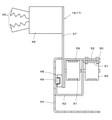
この種のものとして図7~9に示した装置が従来から知られている。
この従来の装置は、図示していない基台に一対の給紙用ロール1,2を設け、この給紙用ロール1,2に包装紙3,4を巻いている。そして、これら包装紙3,4は図7に示すように接着機構Sに挟まれて集約される。なお、これら包装紙3,4はそれらの合せ面側に図示していない樹脂製クッション材を貼り合せている。
The devices shown in FIGS. 7 to 9 are conventionally known as this type.
In this conventional device, a pair of
さらに上記基台であって、包装紙3,4の搬送方向上流側に第1搬送ベルト5が設けられ、この第1搬送ベルト5に載せられた被包装物6は上記接着機構Sに向かって搬送されるとともに、この接着機構Sの手前で包装紙3,4に挟み込まれる。
Further, a
上記接着機構Sは、上記基台に設けられるとともに、図8に示すように、上側接着体7と下側接着体8とからなり、上側接着体7には図示していないヒーターが組み込まれている。
また、上側接着体7は図示していないアクチュエータによって、上記下側接着体8と密着する接着位置(図7,8参照)と下側接着体8から離れる開放位置との間で上下動可能にしている。
The adhesive mechanism S is provided on the base and is composed of an
Further, the upper
さらに、上記両接着体7,8は、包装紙3,4の搬送方向に直交する横部材9,10と、上記搬送方向に平行にするとともに所定の間隔を保った一対の縦部材11及び一対の縦部材12とからなる。
また、上記下側接着体8の横部材10には、その長手方向全長にわたって隙間10aを形成し、この隙間10aのほぼ全長にわたって、すなわち上記包装紙3,4の紙幅と同じ長さのカッター13を上下動可能に組み込んでいる。
Further, the two
Further, a
上記カッター13は、図8に示すように、上記基台に固定したアクチュエータ14によって上下移動可能であり、カッター13の刃先が、上記上側接着体7の横部材9に形成した凹部9a内まで突出できるようにしている。なお、上記カッター13、アクチュエータ14が連続包装紙カット機構Cを構成する。
As shown in FIG. 8, the
したがって、上側接着体7と下側接着体8との間に挟まれた包装紙3,4は、それらの合せ面に設けた上記樹脂製クッション材同士が上記ヒーターの熱で溶着されるとともに、下側接着体8に組み込まれたカッター13によって、包装紙3,4の搬送方向の連続性がカットされることになる。
なお、符号15は接着機構Sの下方に設けられた第2搬送ベルトである。
Therefore, in the wrapping
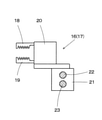
さらに、上記第2搬送ベルト15の搬送方向に沿って移動する、一対の引出用グリップ機構16,17を設けている。上記引出用グリップ機構16,17は、図9に示すように一対のグリップ爪18,19を主要素にし、アクチュエータ20の駆動力でこれらグリップ爪18,19が開閉するようにしている。
Further, a pair of
また、上記アクチュエータ20は、スライダ21に固定しているが、このスライダ21は上記基台に架設したスクリューシャフト22及びガイドシャフト23に支持されている。これらスクリューシャフト22及びガイドシャフト23のそれぞれは、搬送される包装紙3,4の両サイドに平行に設けられたもので、図示していないモータを駆動してスクリューシャフト22を回転させると、引出用グリップ機構16,17が上記包装紙3,4のサイドに沿って移動する。
Further, the
上記のようにした包装装置は、作業の流れのスタート時点では、給紙用ロール1,2の包装紙3,4を接着機構Sの横部材9,10の位置まで手動で引き出して、それらを横部材9,10間で挟み込むとともに、横部材9の上記ヒーターによって合せ面の上記樹脂製クッション材を熱溶着する。
At the start of the work flow, the wrapping device as described above manually pulls out the wrapping
上記のように熱溶着したら上側接着体7と下側接着体8とを離間させるとともに、スクリューシャフト22を回転させて引出用グリップ機構16,17を、上記連続包装紙カット機構Cより包装紙3,4の搬送方向上流側まで移動させ、両接着体7,8の対向部間にとどまっている包装紙3,4の先端両サイドの貼り合せ面をグリップ爪18,19間に導入する。なお、このように上記包装紙3,4の両サイドをグリップ爪18,19間に導入する位置を、引出用グリップ機構16,17のスタート位置X1としている。
After heat welding as described above, the upper
上記のようにグリップ爪18,19間に包装紙3,4の両サイドを導入したら、アクチュエータ20を駆動してグリップ爪18,19を閉じ、上記包装紙3,4の両サイドを引出用グリップ機構16,17でグリップする。
なお、上記のように引出用グリップ機構16,17で重ね合わされた上記包装紙3,4の両サイドをグリップする過程で、第1搬送ベルト5に載せた被包装物6が上記包装紙3,4間に送り込まれる。
After introducing both sides of the wrapping
In the process of gripping both sides of the wrapping
そして、スクリューシャフト22を回転させて、引出用グリップ機構16,17を上記スタート位置X1から、図8に示した引出終了位置X2まで移動して被包装物6を挟み込んだ包装紙3,4を上記引出終了位置X2まで引き出す。
Then, the
引出用グリップ機構16,17が上記引出終了位置X2まで移動したら、離間させていた上側接着体7及び下側接着体8を圧接して、被包装物6の周囲における包装紙3,4の合せ面を熱溶着するとともに、連続包装紙カット機構Cのカッター13を上昇させて包装紙3,4の連続を遮断する。
After the
上記のように包装紙3,4の周囲が熱溶着されるとともに、その連続が断たれた段階で、被包装物6単位の単位包装袋Bが出来上がるが、このとき包装紙3,4の幅方向端部である両サイドには貼り合せ残部24,25ができる。
このように貼り合せ残部24,25ができるのは、包装紙3,4の幅を、いろいろな大きさの被包装物6に対応させるため、常に大きめに設定しているからである。
As described above, the periphery of the wrapping
The reason why the
また、上記したように包装紙3,4の周囲が熱溶着された状態で、連続包装紙カット機構Cで包装紙3,4の連続性が断たれれば、先端が熱溶着された包装紙3,4は、その先端が上記スタート位置X1近傍に留まることになる。
したがって、引出用グリップ機構16,17を再びスタート位置X1に復帰させて、上記した各ステップをくり返すことによって、被包装物6を連続的に包装することができる。
そして、後続の包装紙3,4との連続が遮断された単位包装袋Bは上記第2搬送ベルト15によってこの包装装置から次工程へ送り出される。
Further, if the continuous wrapping paper cutting mechanism C breaks the continuity of the wrapping
Therefore, the object to be packaged 6 can be continuously packaged by returning the pull-out
Then, the unit wrapping bag B whose continuity with the
なお、上記各ステップのタイミングと動作とを系統的に制御するために、図示していないコンピュータによる制御機構が基台に搭載されている。
また、上記した従来技術はごく一般的なものであり、特許調査はしていない。
In addition, in order to systematically control the timing and operation of each of the above steps, a control mechanism by a computer (not shown) is mounted on the base.
In addition, the above-mentioned conventional technique is very general, and no patent search has been conducted.
上記のようにした従来の包装装置では、単位包装袋Bの両サイドに大きな貼り合せ残部24,25ができてしまう。その大きな原因は、先にも説明したように、いろいろな大きさの被包装物6に対応するために包装紙3,4の紙幅を大きめに設定しているからである。
しかし、宅配便などの料金体系が、単位包装袋Bの外形寸法によって決まることが多い。
In the conventional packaging device as described above,
However, the charge system for courier services is often determined by the external dimensions of the unit packaging bag B.
そのために上記貼り合せ残部24,25を含めた単位包装袋Bの外形寸法が、規定の大きさを少しでも上回ってしまうと、ワンランク上の料金が求められてしまう。
特に、被包装物6がそれほど大きくなくても、包装に直接寄与しない貼り合せ残部24,25のために配送料がかさむという不合理な状況が発生してしまう。
このような不合理な状況を回避するために、極端な場合には、人がハサミなどのカッターで貼り合せ残部24,25の一部を切り落としていた。
Therefore, if the external dimensions of the unit packaging bag B including the
In particular, even if the object to be packaged 6 is not so large, an unreasonable situation occurs in which the delivery fee is high due to the
In order to avoid such an unreasonable situation, in an extreme case, a person cuts off a part of the
この発明の目的は、包装に直接寄与しない貼り合せ残部を自動的に切り落として、単位包装袋を必要以上に大きくしない包装装置を提供することである。 An object of the present invention is to provide a packaging device that automatically cuts off the bonding residue that does not directly contribute to packaging and does not make the unit packaging bag larger than necessary.
この発明は、包装紙が巻き付けられるとともに所定の対向間隔を保った一対の給紙用ロールと、被包装物が挟み込まれた上記包装紙の周囲を接着する接着機構と、上記被包装物が挟み込まれた包装紙と後続の包装紙とをカットして被包装物単位で単位包装袋を形成する連続包装紙カット機構と、あらかじめ対向間隔が設定され、上記単位包装袋の搬送方向に平行な一対のカッターからなる残部カット機構と、上記単位包装袋を上記カッター間に連続的に搬送する搬送機構とを備え、上記単位包装袋において搬送方向に沿って両側にはみ出した貼り合せ残部を上記カッターでカットして当該単位包装袋の幅寸法を上記対向間隔の範囲内に保つ包装装置を前提にする。 In the present invention, a pair of feeding rolls in which a wrapping paper is wound and a predetermined facing interval is maintained, an adhesive mechanism for adhering the periphery of the wrapping paper in which the object to be packaged is sandwiched, and the object to be packaged are sandwiched. A pair of continuous wrapping paper cutting mechanism that cuts the wrapping paper and the subsequent wrapping paper to form a unit wrapping bag for each object to be packaged, and a pair of facing intervals set in advance and parallel to the transport direction of the unit wrapping bag. It is equipped with a balance cutting mechanism consisting of the cutters of the above and a transport mechanism for continuously transporting the unit packaging bag between the cutters. It is premised on a packaging device that cuts and keeps the width dimension of the unit packaging bag within the range of the facing spacing .
上記の包装装置を前提にしつつ、第1の発明は、上記搬送機構が、上記単位包装袋の搬送方向に対して平行移動する一対の残部カット用グリップ機構からなり、これら残部カット用グリップ機構は、上記連続包装カット機構によって後続の包装紙がカットされて形成された上記単位包装袋の両サイド先端側の上記貼り合せ残部をグリップする中継位置から、当該単位包装袋を上記一対のカッター間に位置させるカット位置まで移動し、上記残部カット用グリップ機構によって搬送された上記単位包装体の貼り合せ残部が、上記残部カット機構のカッターによってカットされる構成にしている。 On the premise of the above-mentioned packaging device, the first invention comprises a pair of grip mechanisms for cutting the balance in which the transport mechanism moves in parallel with the transport direction of the unit packaging bag. From the relay position that grips the bonded residue on both side tip sides of the unit wrapping bag formed by cutting the subsequent wrapping paper by the continuous wrapping cut mechanism, the unit wrapping bag is placed between the pair of cutters. The structure is such that the bonded residual portion of the unit package, which is moved to the cut position to be positioned and is conveyed by the grip mechanism for cutting the residual portion, is cut by the cutter of the residual cut mechanism.
第2の発明は、上記残部カット用グリップ機構の移動軌跡の上記単位包装袋の搬送方向の上流側の延長上には、上記単位包装袋の搬送方向に対して平行移動可能にした一対の引出用グリップ機構が設けられ、これら引出用グリップ機構は、上記単位包装袋に後続する上記包装紙の両サイド先端側において上記貼り合せ残部に相当する個所をグリップするスタート位置から、上記単位包装袋を上記中継位置に位置する残部カット用グリップ機構に受け渡し可能な引出終了位置まで移動し、その後に上記スタート位置に復帰する。 The second invention is a pair of drawers that can move in parallel to the transport direction of the unit packaging bag on the extension of the movement locus of the grip mechanism for cutting the remaining portion on the upstream side in the transport direction of the unit package bag. Grip mechanisms for pulling out are provided, and these pull-out grip mechanisms hold the unit wrapping bag from a start position that grips a portion corresponding to the remaining bonded portion on both side tip sides of the wrapping paper following the unit wrapping bag. It moves to the withdrawal end position that can be delivered to the remaining cut grip mechanism located at the relay position, and then returns to the start position.
なお、引出用グリップ機構の上記スタート位置は、引出用グリップ機構のストロークの範囲内にあって、上記包装紙の上記貼り合せ残部に相当する個所をグリップする初期位置であれば上記ストローク端である必要はない。 The start position of the pull-out grip mechanism is the stroke end if it is within the stroke range of the pull-out grip mechanism and is the initial position for gripping the portion corresponding to the bonding residue of the wrapping paper. No need.
第3の発明は、後続の包装紙からカットされた上記単位包装袋を、上記接着機構が挟持している間に、上記残部カット用グリップ機構が、上記中継位置に移動してその中継位置における貼り合せ残部をグリップするステップと、上記残部カット用グリップ機構が上記貼り合せ残部をグリップした後に上記接着機構の挟持力を開放するステップと、上記残部カット用グリップ機構を上記カット位置に移動させるステップと、上記残部カット機構が貼り合せ残部を挟持した後に上記残部カット用グリップ機構のグリップ力を開放するとともにこの残部カット用グリップ機構を上記中継位置方向に移動させるステップと、上記残部カット機構のカッターが上記カット位置において単位包装袋の貼り合せ残部を挟持してカットするステップと、を制御する制御機構が備えられている。 In the third invention, while the adhesive mechanism sandwiches the unit wrapping bag cut from the subsequent wrapping paper, the residual cutting grip mechanism moves to the relay position and the relay position thereof. The step of gripping the remaining portion of the bonding, the step of releasing the holding force of the adhesive mechanism after the grip mechanism for cutting the remaining portion grips the remaining portion of the bonding , and the grip mechanism for cutting the remaining portion at the cutting position. A step of moving, a step of releasing the grip force of the grip mechanism for cutting the balance after the remaining cut mechanism sandwiches the bonded remaining portion, and a step of moving the grip mechanism for cutting the remaining portion in the direction of the relay position, and a step of cutting the remaining portion. A control mechanism is provided for controlling the step in which the cutter of the mechanism sandwiches and cuts the bonded remaining portion of the unit packaging bag at the above-mentioned cutting position.
この発明の包装装置によれば、包装に寄与しない貼り合せ残部を自動的に切り落として単位包装袋の大きさを小さくできるので、従来のように配送料を節約するために、人が当該貼り合せ残部を切り落とすような不合理が解消される。 According to the packaging device of the present invention, the size of the unit packaging bag can be reduced by automatically cutting off the bonding residue that does not contribute to packaging, so that a person can perform the bonding in order to save the shipping fee as in the conventional case. The absurdity of cutting off the rest is eliminated.
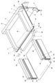
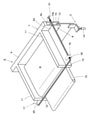
図1~図3に示す第1実施形態は次の点で上記従来の構成と同じである。
すなわち、上記一対の包装紙3,4の先端を上記接着機構Sで接着するステップと、上記引出用グリップ機構16,17をスタート位置X1に保持するステップと、このスタート位置X1において、後続の包装紙3,4の貼り合せ残部24,25に相当する部分を引出用グリップ機構16,17でグリップするステップと、貼り合せ残部24,25に相当する上記部分をグリップした引出用グリップ機構16,17を上記引出終了位置X2まで移動させるステップと、上記引出用グリップ機構16,17が引出終了位置X2に移動した段階で上記接着機構Sが包装紙3,4の縁を接着するとともに、連続包装紙カット機構Cで包装紙3,4をカットして被包装物6単位で単位包装袋Bを形成するステップとを実行する構成及びこれらのステップを系統的に制御する制御機構を設けた点は、すべて従来と同じである。
したがって、この第1実施形態の説明において、従来と同一の構成要素については同一符号を用いる。
The first embodiment shown in FIGS. 1 to 3 is the same as the conventional configuration in the following points.
That is, a step of adhering the tips of the pair of
Therefore, in the description of the first embodiment, the same reference numerals are used for the same components as the conventional ones.
この第1実施形態では、引出用グリップ機構16,17のスタート位置X1から引出終了位置X2までの長さが、単位包装袋Bの長さを決めることになるので、その移動ストロークを調整することによって、単位包装袋Bの大きさを調整することができる。
また、上記上側接着体7にヒーターを組み込んで、包装紙3,4の貼り合せ面に設けた樹脂製クッション材を溶着するようにしたが、下側接着体8にヒーターを組み込んだり、上下側接着体7,8両方にヒーターを組み込んだりしてもよい。
さらに、包装紙3,4の裏面に圧力が作用したときに接着力を発揮する接着剤を塗布し、上側接着体7と下側接着体8との圧接力だけで上記貼り合せ面を接着するようにしてもよい。
さらにまた、上側接着体7及び下側接着体8の両方を上下移動させるようにしてもよい。
In this first embodiment, the length from the start position X1 of the
Further, a heater was incorporated in the upper
Further, an adhesive that exerts an adhesive force when pressure is applied to the back surfaces of the
Furthermore, both the
また、この第1実施形態では、図7に示す上記第2搬送ベルト15に換えて上記単位包装袋Bの底面を支持するテーブルTを設けている。ただし、上記第2搬送ベルト15を備えて上記単位包装袋Bを搬送するようにしてもよい。
そして、このテーブルTの延長上には排出用搬送ベルト26を設けるとともに、この排出用搬送ベルト26に沿って、図2に示すように、一対の残部カット機構27,28を平行に設けている。このようにした残部カット機構27,28は上記排出用搬送ベルト26の搬送方向と平行であるとともに、それらの対向間隔を、単位包装袋Bの包装に寄与していない貼り合せ残部24,25を切り落とすことができるように定めている。したがって、この対向間隔によって、配送料金を決めるときの単位包装袋Bの幅寸法が決まることになる。
Further, in the first embodiment, instead of the
A
なお、上記残部カット機構27,28の対向間隔を調整可能にしておけば、単位包装袋Bの幅寸法を自由に設定することができる。さらに、上記した引出用グリップ機構16,17のスタート位置X1から引出終了位置X2までのストロークを調整して単位包装袋Bの搬送方向の長さを調整すれば、単位包装袋Bの全体の大きさを決めることができる。
If the facing intervals of the remaining
また、上記残部カット機構27,28は、図2,3に示すように、上側押え部材29と下側押え部材30とを備え、これら両押え部材29,30を上下において対向させている。そして、上側押え部材29は図示しないアクチュエータの駆動力で、下側押え部材30は上記基台に固定した図3に示したアクチュエータ31の駆動力で、上下移動可能にしている。したがって、両押え部材29,30でそれらの間に導入された貼り合せ残部24,25をしっかりと挟持することができる。ただし、上下側押え部材29,30のいずれか一方のみを上下動させるようにしてもよい。
Further, as shown in FIGS. 2 and 3, the remaining
さらに、上記上側押え部材29及び下側押え部材30のそれぞれには、隙間32,33を形成するとともに、下側押え部材30側にはカッター34を設けている。このカッター34は、上記基台に固定したアクチュエータ35の駆動力で上記隙間32,33内を上下に移動できるようにしている。
なお、カッター34は、搬送方向における単位包装袋Bの長さ以上の長さを備えている。
Further,
The
したがって、両押え部材29,30で押さえられた単位包装袋Bであって包装に寄与していない貼り合せ残部24,25はカッター34で切り落とされることになる。
なお、上記上側押え部材29、下側押え部材30、アクチュエータ31,35及びカッター34が相まってこの発明の残部カット機構27,28を構成するものである。
Therefore, the unit packaging bag B pressed by the two
The upper pressing
一方、上記引出用グリップ機構16,17の移動軌跡の延長上であって、上記残部カット機構27,28よりも外側には、図2,3に示す残部カット用グリップ機構36,37を設けている。この残部カット用グリップ機構36,37は図3に示すように、上記基台に固定したアクチュエータ38の駆動力で上下動する押圧部材39と、この押圧部材39と対向する支え板40とを備えている。
On the other hand, on the extension of the movement locus of the pull-out
しかも、上記支え板40は連結板41と一体化されるとともに、上記アクチュエータ38がこの連結板41に固定されている。そして、上記連結板41は外側に90度折れ曲がって上記基台に固定したガイドレール42に摺動自在に支えられるとともに、そのガイドレール42の内側に設けた駆動ベルト43の駆動力で、当該残部カット用グリップ機構36,37は単位包装袋Bの搬送方向に平行移動可能にしている。
Moreover, the
このようにした残部カット用グリップ機構36,37は、引出用グリップ機構16,17で上記引出終了位置X2まで搬送された単位包装袋Bの貼り合せ残部24,25をグリップできる図示の中継位置X3まで移動可能にしている。この中継位置X3は上記引出終了位置X2と同じかほぼ同じ位置である。ただし、図示しない制御機構によって、両グリップ機構が干渉し合うことがないように制御している。
そして、この中継位置X3において貼り合せ残部24,25をグリップした残部カット用グリップ機構36,37は、当該単位包装袋Bを搬送しながらその貼り合せ残部24,25を上記残部カット機構27,28まで移動させる。このときの残部カット用グリップ機構36,37は、残部カット機構27,28の上記搬送方向下流側端部近傍(図1,2参照)のカット位置X4まで移動し、上記貼り合せ残部24,25の全長が残部カット機構27,28内に収まるようにしている。
The remaining
Then, the
上記のように単位包装袋Bを上記残部カット機構27,28まで移動させたら、残部カット機構27,28の上側押え部材29と下側押え部材30とを移動させて単位包装袋Bの貼り合せ残部24,25を両押え部材29,30でしっかりと挟持する。
そして、カッター34を上昇させて包装に寄与していない貼り合せ残部24,25をカットする。
なお、上記残部カット機構27,28の上記搬送方向に沿った長さを単位包装袋Bの長さより長くして、貼り合せ残部24,25が全長にわたってカットされるようにしている。
After moving the unit packaging bag B to the remaining
Then, the
The length of the remaining
さらに、単位包装袋Bを作り出すプロセスと、上記貼り合せ残部24,25をカットするまでのプロセスとを、図示していない制御機構で系統的に制御できるようにしている。
すなわち、一対の包装紙3,4の先端を上記接着機構Sで接着するステップと、引出用グリップ機構16,17を上記スタート位置X1に保持するステップと、上記スタート位置X1において包装紙3,4の貼り合せ残部24,25に相当する部分を引出用グリップ機構16,17でグリップするステップと、貼り合せ残部24,25に相当する部分をグリップした引出用グリップ機構16,17を上記引出終了位置X2まで移動させてグリップを継続するステップと、引出用グリップ機構16,17が引出終了位置X2に移動した段階で接着機構Sが包装紙3,4を挟持するとともに、包装紙3,4の周囲を接着して被包装物単位で単位包装袋Bを形成するステップと、接着機構Sが包装紙3,4を挟持した段階で、引出用グリップ機構16,17のグリップ力を開放するとともに、この引出用グリップ機構16,17を上記スタート位置X1方向に移動させるステップと、連続包装紙カット機構Cが上記単位包装袋Bを後続の包装紙3,4からカットするステップと、引出用グリップ機構16,17がグリップ力を開放するとともに接着機構Sが包装紙を挟持している段階で、残部カット用グリップ機構36,37が、上記中継位置X3に移動してその中継位置X3における貼り合せ残部24,25をグリップするステップと、残部カット用グリップ機構36,37が上記のように貼り合せ残部24,25をグリップした段階で接着機構Sの挟持力を開放するステップと、接着機構Sの挟持力が開放されかつ貼り合せ残部24,25をグリップした段階で残部カット用グリップ機構36,37を上記カット位置X4に移動させるステップと、残部カット機構27,28が貼り合せ残部24,25を挟持した段階で残部カット用グリップ機構36,37のグリップ力を開放するとともにこの残部カット用グリップ機構36,37を上記中継位置X3方向に移動させるステップと、残部カット用グリップ機構36,37が中継位置X3に移動して貼り合せ残部24,25から外れた段階で、残部カット機構27,28のカッター34が上記単位包装袋Bの貼り合せ残部24,25をカットするステップと、単位包装袋Bの貼り合せ残部24,25がカットされた段階で、残部カット機構27,28の挟持力を開放するステップと、を上記制御機構が系統的に制御する。
Further, the process of creating the unit packaging bag B and the process of cutting the bonded
That is, a step of adhering the tips of the pair of
そして、上記残部カット機構27,28から開放された単位包装袋Bは、排出用搬送ベルト26によってこの包装装置から次工程へ送り出される。なお、排出用搬送ベルト26は、残部カット用グリップ機構36,37が単位包装袋Bを搬送しているときには、停止状態を保っていてもよいし、残部カット用グリップ機構36,37と同期して単位包装袋Bの搬送を補助するようにしてもよい。
Then, the unit packaging bag B released from the remaining
上記のように制御機構が各ステップを制御することによって、一連のステップを実行するプロセスで、包装紙3,4あるいは単位包装袋Bの貼り合せ残部24が、何らかの形で必ず保持されていることになり、それらの位置ずれを防止している。
このように位置ずれが防止されるので、残部カット機構27,28によるカット位置も正確に保たれ、単位包装袋Bの両サイドの貼り合せ残部24,25が常に平行に、しかも設定された幅だけカットされる。
In the process of executing a series of steps by controlling each step by the control mechanism as described above, the wrapping
Since the misalignment is prevented in this way, the cutting position by the remaining
また、残部カット用グリップ機構36,37が、上記カット位置X4から中継位置X3方向へ移動して貼り合せ残部24,25から外れた段階で、残部カット機構27,28のカッター34が上記カット位置において単位包装袋Bの貼り合せ残部24,25をカットするようにしたので、例えば、カットされて落ちる貼り合せ残部24,25が残部カット用グリップ機構36,37に絡まるようなこともなくなる。
Further, when the
また、第1実施形態では、引出用グリップ機構16,17がそのスタート位置X1で接着された包装紙3,4の先端をグリップし、そのグリップした包装紙3,4の先端を上記引出終了位置X2まで搬送して接着機構Sが当該包装紙3,4を挟持した段階で、引出用グリップ機構16,17はそのグリップ力を開放してスタート位置X1方向に移動する。なお、このときには、接着機構Sが挟持位置を保っているので、引出用グリップ機構16,17は、接着機構Sの横部材9,10の手前で待機している。そして、接着機構Sの上側接着体7と下側接着体8とが離間したとき、引出用グリップ機構16,17のグリップ爪18,19が上側接着体7と下側接着体8との間を通過して上記スタート位置X1に復帰する。
Further, in the first embodiment, the
このように上記スタート位置X1から上記カット位置X4までの移動過程で、引出用グリップ機構16,17と残部カット用グリップ機構36,37とで上記単位包装袋Bを受け渡しできるようにしたので、その搬送速度を高速化させることができる。
例えば、引出用グリップ機構16,17だけでスタート位置X1からカット位置X4まで搬送すると、その戻り時のストークが長くなるので、その分スピードが遅くなる。スタート位置までの戻りスピードが遅くなれば、次のプロセスのスタートが遅れることになるので、全体の処理速度も遅くなってしまう。
しかし、上記したように、引出用グリップ機構16,17が引出終了位置X2まで移動したら即座にスタート位置X1方向に移動して、次のプロセスを滞りなくスタートさせるとともに、その間に、残部カット用グリップ機構36,37がカット位置X4まで移動するので、各プロセスを連続的にしかも迅速に処理することができる。
In this way, in the process of moving from the start position X1 to the cut position X4, the unit packaging bag B can be delivered by the
For example, if the pull-out
However, as described above, as soon as the
なお、上記引出用グリップ機構16,17の引出終了位置X2と、残部カット用グリップ機構36,37の中継位置X3とは、それらが全く同じでもよいし、多少ずれていてもよい。全く同じであっても、引出用グリップ機構16,17が引出終了位置X2に位置しているタイミングと、残部カット用グリップ機構36,37が中継位置に到達するタイミングとをずらしているので、引出用グリップ機構16,17と残部カット用グリップ機構36,37とが干渉しあうことはない。
The drawer end positions X2 of the
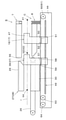
図4~6に示す第2実施形態は、図2に示す上記貼り合せ残部24,25をグリップして単位包装袋Bを搬送する引出用グリップ機構16,17と残部カット用グリップ機構36,37の構成や、その支持機構が上記第1実施形態とは異なるが、その他の構成や作用は上記第1実施形態と同じである。
この第2実施形態の説明において、第1実施形態と同一の構成要素については同一符号を用いる。
したがって、以下の説明にも図1,2を参照し、第1実施形態と異なる部分を中心に説明する。
In the second embodiment shown in FIGS. 4 to 6, the
In the description of the second embodiment, the same reference numerals are used for the same components as those of the first embodiment.
Therefore, with reference to FIGS. 1 and 2 in the following description, the parts different from the first embodiment will be mainly described.
この第2実施形態では、上記接着機構S及び残部カット機構27,28の両外側に、単位包装袋Bの搬送方向に長さを有する図4に示した取付板44が設けられている。この取付板44は上記基台上に起立して設けられ、この取付板44に、上記引出用グリップ機構16,17と、残部カット用グリップ機構36,37とが、図4に示す上記単位包装袋Bの搬送路rに沿って移動可能に設けられている。
In the second embodiment, the mounting
上記取付板44は、上記接着機構S及び残部カット機構27,28を挟んだ両側に設けられ、一方の取付板44に引出用グリップ機構16と残部カット用グリップ機構36が取り付けられ、他方の取付板44には引出用グリップ機構17と残部カット用グリップ機構37とが取り付けられている。ただし、図4には一方の引出用グリップ機構16と残部カット用グリップ機構36のみを示している。
そして、上記搬送路rを挟んで対向するグリップ機構同士は互いに線対称の形状で、同様に動作するので、片側のみを示す図4~6を用いて両側のグリップ機構について説明する。
図5は、引出用グリップ機構16,17及び残部カット用グリップ機構36,37の取り付け部分を表わした部分平面図であるが、上記取付板44を省略している。また、図6は、図5のVI-VI線断図であって、引出用グリップ機構16,17を上記搬送方向下流側から見た図である。
The mounting
Since the grip mechanisms facing each other across the transport path r have a shape of line symmetry and operate in the same manner, the grip mechanisms on both sides will be described with reference to FIGS. 4 to 6 showing only one side.
FIG. 5 is a partial plan view showing the mounting portions of the pull-out
図6に示すように、上記引出用グリップ機構16,17は、一対のグリップ爪45,45とこれらグリップ爪45,45を開閉させるアクチュエータ46とを備え、このアクチュエータ46が上記取付板44と平行にした支持板47に固定されている。
また、上記支持板47には、取付板44側に開口部を備えたスライダ48が固定され、このスライダ48を、上記取付板44に固定したガイドレール49に嵌め合せて引出用グリップ機構16,17をガイドレール49に沿って移動可能に支持している。
さらに、上記支持板47には、この支持板47に対して直角で外方に突出する連結板50が固定され、この連結板50と挟持部材51とで第1駆動ベルト52を挟持している。
As shown in FIG. 6, the
Further, a
Further, a connecting
また、図4,5に示す残部カット用グリップ機構36,37は、上記引出用グリップ機構16,17と同様の構成を備えている。
すなわち、残部カット用グリップ機構36,37は、それぞれ、上記グリップ爪45,45と同様の一対のグリップ爪53,53と、これらを開閉させるアクチュエータ54とを備えている。上記アクチュエータ54は、支持板55に固定されるとともに、この支持板55には、上記ガイドレール49を共通にしたスライダ56を固定して、残部カット用グリップ機構36,37を移動可能に支持している(図5参照)。
Further, the remaining
That is, the
また、図5に示すように、上記支持板55には、上記連結板50と同様に支持板55に対して直角で外方へ突出する連結板57を固定し、この連結板57と挟持部材58(図4参照)とによって第2駆動ベルト59を挟持している。
なお、上記連結板57の外方への突出量を、引出用グリップ機構16,17の連結板50の突出量よりも小さくし、平行に配置された第1,2駆動ベルト52,59に対応している。
Further, as shown in FIG. 5, a connecting
The amount of protrusion of the connecting
一方、上記ガイドレール49は、単位包装袋Bの搬送路rに沿って取付板44に固定されている。このガイドレール49は、上記した引出用グリップ機構16,17のスタート位置X1から残部カット用グリップ機構36,37のカット位置X4までに対応する長さを備えている。
また、図4に示すように、取付板44には、上記スタート位置X1よりも上流側となる位置に、自由回転可能にした従動プーリー60,61が設けられている。これら従動プーリー60,61のうち一方の従動プーリー60は中継部材62に回転自在に支持されて上記取付板44との間に十分な距離を保っている。また、従動プーリー61は、一方の従動プーリー60の内側にあって取付板44に回転自在に支持されている。ただし、これら従動プーリー60,61はそれらの回転軸線をほぼ一致させている。
On the other hand, the
Further, as shown in FIG. 4, the mounting
さらに、取付板44の下流端側には、それぞれ図示しない駆動源に連結された駆動プーリー63,64を設けている(図4参照)。
そして、一方の駆動プーリー63を上記従動プーリー60に対応させてこれら一対のプーリー63,60に上記第1駆動ベルト52を掛け渡している。また、他方の駆動プーリー64を上記従動プーリー61に対応させて、これら一対のプーリー61,64に上記第2駆動ベルト59を掛け渡している。これにより、互いに平行に配置された上記第1,2駆動ベルト52,59は、上記搬送路rに沿って移動可能になる。
したがって、駆動プーリー63,64を制御すれば、第1,2駆動ベルト52,59が駆動し、その駆動力によって引出用グリップ機構16,17や残部カット用グリップ機構36,37を移動させることができる。
Further, drive pulleys 63 and 64 connected to drive sources (not shown) are provided on the downstream end side of the mounting plate 44 (see FIG. 4).
Then, one
Therefore, if the drive pulleys 63 and 64 are controlled, the first and
なお、図5,6に示すように引出用グリップ機構16,17の連結板50は残部カット用グリップ機構36,37の第2駆動ベルト59を跨いでいるが、この連結板50が移動したとき、第2駆動ベルト59の表面を摺動しないようにしている。具体的には、連結板50の高さ位置を、連結板50に固定しないで張った状態の第2駆動ベルト59よりも高くして、図6に示すように第2駆動ベルト59の表面との間に隙間を保つようにしている。
また、この第2実施形態では、第2駆動ベルト59側でも、連結板57の位置を上記連結板50と同様に他の部分よりも高くしているが、上記使用に、引出用グリップ機構16,17と残部カット用グリップ機構36,37とが上記搬送路r上の同一点に位置することはないので、連結板50が第2駆動ベルト59の表面を摺動することはない。
As shown in FIGS. 5 and 6, the connecting
Further, in the second embodiment, the position of the connecting
このようにした第2実施形態でも、上記制御手段は第1実施形態と同様に機能し、上記接着機構Sや連続包装紙カット機構C、残部カット機構27,28、引出用グリップ機構16,17、残部カット用グリップ機構36,37を系統的に制御するステップを実行する。
その結果、単位包装袋Bの貼り合せ残部24,25の包装に寄与しない余分な部分を自動的にカットして、単位包装袋Bの外形寸法を配送料金の規格内に納めることができる。
In the second embodiment as described above, the control means functions in the same manner as in the first embodiment, and the adhesive mechanism S, the continuous wrapping paper cutting mechanism C, the
As a result, it is possible to automatically cut the excess portion of the bonded remaining
また、この第2実施形態では、1本のガイドレール49が、引出用グリップ機構16,17と残部カット用グリップ機構36、37とを支持し、両グリップ機構の駆動手段である第1,2駆動ベルト52,59をガイドレール49に沿って設けている。そのため、第1実施形態のように、引出用グリップ機構16,17の駆動手段と、残部カット用グリップ機構36,37の駆動手段とを別々にしてそれぞれにスクリューシャフト22やガイドレール42を備え、それらを離して設けている場合と比べて、装置をコンパクトにすることができる。
Further, in the second embodiment, one
また、共通のガイドレール49を基準にして、引出用グリップ機構16,17及び残部カット用グリップ機構36,37のグリップ位置を設定できるので、例えば、引出用グリップ機構16,17のグリップ爪45の高さ位置と残部カット用グリップ機構36,37のグリップ爪53の高さ位置を一致させやすい。このように、グリップ爪45とグリップ爪53の高さ位置を一致させ、上記搬送路rに合わせることができれば、単位包装袋Bの受け渡しがスムーズにできる。
Further, since the grip positions of the
さらに、この第2実施形態でも、引出用グリップ機構16,17と残部カット用グリップ機構36,37とを別部材にして個別に制御することで、単位包装袋Bの連続搬送と、搬送速度の高速化とを可能にしている。ただし、引出用グリップ機構16,17が残部カット用グリップ機構36,37を兼ねて、上記ガイドレール49に沿ってスタート位置X1とカット位置X4との間を往復移動するようにしてもよい。この場合には、引出用グリップ機構16,17と残部カット用グリップ機構36,37とを別々に制御する上記実施形態と比べて処理スピードが落ちることになるが、包装に寄与しない貼り合せ残部24,25を自動的にかつ確実にカットできることは変わらずに、装置構成や制御を簡略化できる。
Further, also in this second embodiment, the pull-out
なお、第1,2実施形態の引出用グリップ機構や残部カット用グリップ機構を移動させる駆動手段は、上記のような駆動ベルトやスクリューシャフトに限らず、どのようなものでも構わない。
また、単位包装袋Bの搬送手段も、上記グリップ機構に限らない。例えば、搬送ベルトによって単位包装袋Bを残部カット機構27,28へ搬送してもよい。ただし、搬送ベルトでは単位包装袋Bの搬送方向がずれやすいので、位置ずれが起こらない構成が必要である。搬送方向がずれてしまうと、残部カット機構27,28と貼り合せ残部24,25との位置関係もずれてしまって、単位包装袋Bの外形寸法を目的の大きさにすることができなかったり、単位包装袋Bを壊してしまったりすることがあるからである。
これに対し、上記のように両サイドの貼り合せ残部24,25をグリップして搬送すれば、単位包装袋Bの搬送方向がずれてしまうことがなく、正確なカットができる。
The drive means for moving the drawer grip mechanism and the residual cut grip mechanism of the first and second embodiments is not limited to the drive belt and the screw shaft as described above, and may be any.
Further, the means for transporting the unit packaging bag B is not limited to the above-mentioned grip mechanism. For example, the unit packaging bag B may be transported to the
On the other hand, if the bonding balances 24 and 25 on both sides are gripped and transported as described above, the transport direction of the unit packaging bag B does not shift, and accurate cutting can be performed.
書籍などを規定の配送料金の範囲内で包装するのに適している。 Suitable for packaging books, etc. within the specified shipping fee.
S…接着機構、C…連続包装紙カット機構、6…被包装物、13…カッター、16,17…引出用グリップ機構、B…単位包装袋、24,24…貼り合せ残部、27,28…残部カット機構、34…カッター、36,37…残部カット用グリップ機構、49…ガイドレール、X1…スタート位置、X2…引出終了位置、X3…中継位置、X4…カット位置 S ... Adhesive mechanism, C ... Continuous wrapping paper cutting mechanism, 6 ... Object to be packaged, 13 ... Cutter, 16, 17 ... Drawer grip mechanism, B ... Unit wrapping bag, 24, 24 ... Bonding balance, 27, 28 ... Remaining cut mechanism, 34 ... Cutter, 36, 37 ... Remaining cut grip mechanism, 49 ... Guide rail, X1 ... Start position, X2 ... Drawer end position, X3 ... Relay position, X4 ... Cut position
Claims (3)
被包装物が挟み込まれた上記包装紙の周囲を接着する接着機構と、
上記被包装物が挟み込まれた包装紙と後続の包装紙とをカットして被包装物単位で単位包装袋を形成する連続包装紙カット機構と、
あらかじめ対向間隔が設定され、上記単位包装袋の搬送方向に平行な一対のカッターからなる残部カット機構と、
上記単位包装袋を上記カッター間に連続的に搬送する搬送機構とを備え、
上記単位包装袋において搬送方向に沿って両側にはみ出した貼り合せ残部を上記カッターでカットして当該単位包装袋の幅寸法を上記対向間隔の範囲内に保つ包装装置であって、
上記搬送機構が、上記単位包装袋の搬送方向に対して平行移動する一対の残部カット用グリップ機構からなり、
これら残部カット用グリップ機構は、
上記連続包装カット機構によって後続の包装紙がカットされて形成された上記単位包装袋の両サイド先端側の上記貼り合せ残部をグリップする中継位置から、当該単位包装袋を上記一対のカッター間に位置させるカット位置まで移動し、
上記残部カット用グリップ機構によって搬送された上記単位包装体の貼り合せ残部が、上記残部カット機構のカッターによってカットされる構成にした包装装置。 A pair of paper feed rolls on which the wrapping paper is wrapped and kept a predetermined facing interval,
An adhesive mechanism that adheres around the wrapping paper in which the object to be packaged is sandwiched,
A continuous wrapping paper cutting mechanism that cuts the wrapping paper in which the object to be packaged is sandwiched and the subsequent wrapping paper to form a unit wrapping bag for each packaged object.
A balance cutting mechanism consisting of a pair of cutters whose facing spacing is set in advance and parallel to the transport direction of the unit packaging bag,
Equipped with a transport mechanism that continuously transports the unit packaging bag between the cutters.
A packaging device that keeps the width dimension of the unit packaging bag within the range of the facing spacing by cutting the bonded residue protruding from both sides along the transport direction with the cutter.
The transport mechanism comprises a pair of grip mechanisms for cutting the balance that move in parallel with the transport direction of the unit packaging bag.
These grip mechanisms for cutting the rest are
The unit wrapping bag is positioned between the pair of cutters from the relay position that grips the bonded residue on both side tip sides of the unit wrapping bag formed by cutting the subsequent wrapping paper by the continuous wrapping cut mechanism. Move to the cut position to make
A packaging device having a structure in which the bonded residual portion of the unit package conveyed by the grip mechanism for cutting the remaining portion is cut by the cutter of the residual cutting mechanism.
これら引出用グリップ機構は、
上記単位包装袋に後続する上記包装紙の両サイド先端側において上記貼り合せ残部に相当する個所をグリップするスタート位置から、上記単位包装袋を上記中継位置に位置する残部カット用グリップ機構に受け渡し可能な引き出し終了位置まで移動し、その後に上記スタート位置に復帰する構成にした請求項1に記載の包装装置。 A pair of drawer grip mechanisms that can be translated in parallel with the transport direction of the unit packaging bag are provided on the extension of the movement locus of the grip mechanism for cutting the remaining portion on the upstream side in the transport direction of the unit packaging bag. ,
These drawer grip mechanisms
The unit wrapping bag can be delivered to the balance cutting grip mechanism located at the relay position from the start position where the portion corresponding to the bonded balance is gripped on both side tip sides of the wrapping paper following the unit wrapping bag. The packaging device according to claim 1, which is configured to move to a pull-out end position and then return to the start position.
上記残部カット用グリップ機構が上記貼り合せ残部をグリップした後に上記接着機構の挟持力を開放するステップと、
上記残部カット用グリップ機構を上記カット位置に移動させるステップと、
上記残部カット機構が貼り合せ残部を挟持した後に上記残部カット用グリップ機構のグリップ力を開放するとともにこの残部カット用グリップ機構を上記中継位置方向に移動させるステップと、
上記残部カット機構のカッターが上記カット位置において単位包装袋の貼り合せ残部を挟持してカットするステップと、
を制御する制御機構が備えられた請求項2に記載の包装装置。 While the adhesive mechanism holds the unit wrapping bag cut from the subsequent wrapping paper, the residual cutting grip mechanism moves to the relay position and grips the bonded residual at the relay position. Steps and
The step of releasing the holding force of the adhesive mechanism after the grip mechanism for cutting the remaining portion grips the bonded remaining portion, and
The step of moving the grip mechanism for cutting the remaining part to the cutting position,
A step of releasing the grip force of the residual cut grip mechanism after the residual cut mechanism sandwiches the bonded residual and moving the residual cut grip mechanism in the relay position direction.
A step in which the cutter of the balance cutting mechanism sandwiches and cuts the bonded balance of the unit packaging bag at the cutting position.
The packaging device according to claim 2, wherein the packaging device is provided with a control mechanism for controlling.
Priority Applications (1)
| Application Number | Priority Date | Filing Date | Title |
|---|---|---|---|
| JP2021159007A JP7325848B2 (en) | 2019-03-29 | 2021-09-29 | packaging equipment |
Applications Claiming Priority (2)
| Application Number | Priority Date | Filing Date | Title |
|---|---|---|---|
| JP2019067377 | 2019-03-29 | ||
| JP2019067377 | 2019-03-29 |
Related Child Applications (1)
| Application Number | Title | Priority Date | Filing Date |
|---|---|---|---|
| JP2021159007A Division JP7325848B2 (en) | 2019-03-29 | 2021-09-29 | packaging equipment |
Publications (3)
| Publication Number | Publication Date |
|---|---|
| JP2020164246A JP2020164246A (en) | 2020-10-08 |
| JP2020164246A5 JP2020164246A5 (en) | 2021-11-11 |
| JP6998610B2 true JP6998610B2 (en) | 2022-01-18 |
Family
ID=72715702
Family Applications (2)
| Application Number | Title | Priority Date | Filing Date |
|---|---|---|---|
| JP2019199015A Active JP6998610B2 (en) | 2019-03-29 | 2019-10-31 | Packaging equipment |
| JP2021159007A Active JP7325848B2 (en) | 2019-03-29 | 2021-09-29 | packaging equipment |
Family Applications After (1)
| Application Number | Title | Priority Date | Filing Date |
|---|---|---|---|
| JP2021159007A Active JP7325848B2 (en) | 2019-03-29 | 2021-09-29 | packaging equipment |
Country Status (1)
| Country | Link |
|---|---|
| JP (2) | JP6998610B2 (en) |
Families Citing this family (1)
| Publication number | Priority date | Publication date | Assignee | Title |
|---|---|---|---|---|
| JP6998610B2 (en) | 2019-03-29 | 2022-01-18 | 株式会社ダイワハイテックス | Packaging equipment |
Citations (3)
| Publication number | Priority date | Publication date | Assignee | Title |
|---|---|---|---|---|
| JP2002053103A (en) | 2000-08-08 | 2002-02-19 | Fukumi Sangyo Kk | Automatic packaging method and device therefor using cellular sheet |
| JP2006103722A (en) | 2004-10-04 | 2006-04-20 | Fukumi Sangyo Kk | Automatic packaging apparatus |
| US20180141693A1 (en) | 2016-11-23 | 2018-05-24 | Multivac Sepp Haggenmüller Se & Co. Kg | Thermoform packaging machine with pulling device |
Family Cites Families (8)
| Publication number | Priority date | Publication date | Assignee | Title |
|---|---|---|---|---|
| JPS59199403A (en) * | 1983-04-16 | 1984-11-12 | 大森機械工業株式会社 | Packing method |
| JPH0532226A (en) * | 1991-02-27 | 1993-02-09 | Fuji Photo Film Co Ltd | Packing device |
| JPH0751453Y2 (en) * | 1991-09-24 | 1995-11-22 | 株式会社フジキカイ | Excessive seal part cutting device for horizontal bag filling and packaging machine |
| JP2606264Y2 (en) * | 1993-08-30 | 2000-10-10 | 大森機械工業株式会社 | Deep drawing type packaging equipment |
| JPH07195299A (en) * | 1993-12-28 | 1995-08-01 | Shinko Seisakusho Co Ltd | Automatic sealing machine |
| JP4174680B2 (en) | 2004-02-09 | 2008-11-05 | 三菱瓦斯化学株式会社 | Method and apparatus for producing oxygen scavenging bag |
| US20180272620A1 (en) | 2015-12-02 | 2018-09-27 | Swedish Match North Europe Ab | Sealing device |
| JP6998610B2 (en) | 2019-03-29 | 2022-01-18 | 株式会社ダイワハイテックス | Packaging equipment |
-
2019
- 2019-10-31 JP JP2019199015A patent/JP6998610B2/en active Active
-
2021
- 2021-09-29 JP JP2021159007A patent/JP7325848B2/en active Active
Patent Citations (3)
| Publication number | Priority date | Publication date | Assignee | Title |
|---|---|---|---|---|
| JP2002053103A (en) | 2000-08-08 | 2002-02-19 | Fukumi Sangyo Kk | Automatic packaging method and device therefor using cellular sheet |
| JP2006103722A (en) | 2004-10-04 | 2006-04-20 | Fukumi Sangyo Kk | Automatic packaging apparatus |
| US20180141693A1 (en) | 2016-11-23 | 2018-05-24 | Multivac Sepp Haggenmüller Se & Co. Kg | Thermoform packaging machine with pulling device |
Also Published As
| Publication number | Publication date |
|---|---|
| JP2022000397A (en) | 2022-01-04 |
| JP7325848B2 (en) | 2023-08-15 |
| JP2020164246A (en) | 2020-10-08 |
Similar Documents
| Publication | Publication Date | Title |
|---|---|---|
| WO2010010874A1 (en) | Package paper connecting device, package paper connecting method, and packaging apparatus | |
| JP6998610B2 (en) | Packaging equipment | |
| JP3440466B2 (en) | Foil bag manufacturing packing method and apparatus | |
| CN108688902B (en) | Packaging system | |
| JP5097314B2 (en) | Packaging machine | |
| JP2015101436A (en) | Packing tape sticking device | |
| JP5591313B2 (en) | Packaging machine | |
| JP2010137557A (en) | Film cover bonding system | |
| JP2020164246A5 (en) | ||
| TWI798046B (en) | Packing device for box body | |
| JP2012197120A (en) | Film supply device for packaging machine | |
| KR101473619B1 (en) | Packing machine with open and close mechanism of transportation path | |
| JP5577526B2 (en) | Wrapping paper connection device | |
| JP5270212B2 (en) | Packaging equipment | |
| JP4824428B2 (en) | Packaging equipment | |
| JP2015038009A (en) | Wrapping paper connecting device, wrapping paper connecting method, and wrapping device | |
| JP4360668B2 (en) | Tape cutting device and cardboard box making device using the same | |
| JPS587530B2 (en) | box sealing machine | |
| JP2004026160A (en) | Automatic packaging method of kraft envelope with air cap and its device | |
| JP2011063410A (en) | Buffer device and bucket width adjusting method | |
| WO2020105128A1 (en) | Tape length adjustment device | |
| JP7257061B2 (en) | Food sealing device | |
| JP2006103722A (en) | Automatic packaging apparatus | |
| KR200298998Y1 (en) | device for package of note | |
| JP2005162304A (en) | Automatic packing method and automatic packing device |
Legal Events
| Date | Code | Title | Description |
|---|---|---|---|
| A80 | Written request to apply exceptions to lack of novelty of invention |
Free format text: JAPANESE INTERMEDIATE CODE: A80 Effective date: 20191128 |
|
| RD02 | Notification of acceptance of power of attorney |
Free format text: JAPANESE INTERMEDIATE CODE: A7422 Effective date: 20201023 |
|
| A521 | Written amendment |
Free format text: JAPANESE INTERMEDIATE CODE: A523 Effective date: 20210929 |
|
| A621 | Written request for application examination |
Free format text: JAPANESE INTERMEDIATE CODE: A621 Effective date: 20210929 |
|
| A871 | Explanation of circumstances concerning accelerated examination |
Free format text: JAPANESE INTERMEDIATE CODE: A871 Effective date: 20211001 |
|
| A131 | Notification of reasons for refusal |
Free format text: JAPANESE INTERMEDIATE CODE: A131 Effective date: 20211102 |
|
| A621 | Written request for application examination |
Free format text: JAPANESE INTERMEDIATE CODE: A621 Effective date: 20210929 |
|
| A521 | Written amendment |
Free format text: JAPANESE INTERMEDIATE CODE: A523 Effective date: 20211122 |
|
| TRDD | Decision of grant or rejection written | ||
| A01 | Written decision to grant a patent or to grant a registration (utility model) |
Free format text: JAPANESE INTERMEDIATE CODE: A01 Effective date: 20211207 |
|
| A61 | First payment of annual fees (during grant procedure) |
Free format text: JAPANESE INTERMEDIATE CODE: A61 Effective date: 20211214 |
|
| R150 | Certificate of patent or registration of utility model |
Ref document number: 6998610 Country of ref document: JP Free format text: JAPANESE INTERMEDIATE CODE: R150 |