JP6997684B2 - A system and method for rotating a three-dimensional (3D) object while printing the object. - Google Patents
A system and method for rotating a three-dimensional (3D) object while printing the object. Download PDFInfo
- Publication number
- JP6997684B2 JP6997684B2 JP2018135418A JP2018135418A JP6997684B2 JP 6997684 B2 JP6997684 B2 JP 6997684B2 JP 2018135418 A JP2018135418 A JP 2018135418A JP 2018135418 A JP2018135418 A JP 2018135418A JP 6997684 B2 JP6997684 B2 JP 6997684B2
- Authority
- JP
- Japan
- Prior art keywords
- actuator
- holder
- printhead
- controller
- printing system
- Prior art date
- Legal status (The legal status is an assumption and is not a legal conclusion. Google has not performed a legal analysis and makes no representation as to the accuracy of the status listed.)
- Active
Links
Images


Classifications
-
- B—PERFORMING OPERATIONS; TRANSPORTING
- B41—PRINTING; LINING MACHINES; TYPEWRITERS; STAMPS
- B41J—TYPEWRITERS; SELECTIVE PRINTING MECHANISMS, i.e. MECHANISMS PRINTING OTHERWISE THAN FROM A FORME; CORRECTION OF TYPOGRAPHICAL ERRORS
- B41J3/00—Typewriters or selective printing or marking mechanisms characterised by the purpose for which they are constructed
- B41J3/407—Typewriters or selective printing or marking mechanisms characterised by the purpose for which they are constructed for marking on special material
- B41J3/4073—Printing on three-dimensional objects not being in sheet or web form, e.g. spherical or cubic objects
-
- B—PERFORMING OPERATIONS; TRANSPORTING
- B41—PRINTING; LINING MACHINES; TYPEWRITERS; STAMPS
- B41J—TYPEWRITERS; SELECTIVE PRINTING MECHANISMS, i.e. MECHANISMS PRINTING OTHERWISE THAN FROM A FORME; CORRECTION OF TYPOGRAPHICAL ERRORS
- B41J29/00—Details of, or accessories for, typewriters or selective printing mechanisms not otherwise provided for
-
- B—PERFORMING OPERATIONS; TRANSPORTING
- B41—PRINTING; LINING MACHINES; TYPEWRITERS; STAMPS
- B41J—TYPEWRITERS; SELECTIVE PRINTING MECHANISMS, i.e. MECHANISMS PRINTING OTHERWISE THAN FROM A FORME; CORRECTION OF TYPOGRAPHICAL ERRORS
- B41J3/00—Typewriters or selective printing or marking mechanisms characterised by the purpose for which they are constructed
- B41J3/407—Typewriters or selective printing or marking mechanisms characterised by the purpose for which they are constructed for marking on special material
- B41J3/4073—Printing on three-dimensional objects not being in sheet or web form, e.g. spherical or cubic objects
- B41J3/40731—Holders for objects, e. g. holders specially adapted to the shape of the object to be printed or adapted to hold several objects
-
- B—PERFORMING OPERATIONS; TRANSPORTING
- B41—PRINTING; LINING MACHINES; TYPEWRITERS; STAMPS
- B41J—TYPEWRITERS; SELECTIVE PRINTING MECHANISMS, i.e. MECHANISMS PRINTING OTHERWISE THAN FROM A FORME; CORRECTION OF TYPOGRAPHICAL ERRORS
- B41J3/00—Typewriters or selective printing or marking mechanisms characterised by the purpose for which they are constructed
- B41J3/407—Typewriters or selective printing or marking mechanisms characterised by the purpose for which they are constructed for marking on special material
- B41J3/4073—Printing on three-dimensional objects not being in sheet or web form, e.g. spherical or cubic objects
- B41J3/40733—Printing on cylindrical or rotationally symmetrical objects, e. g. on bottles
Description
本開示は、概して、3次元(3D)オブジェクト上に印刷するためのシステムに関し、より具体的には、円筒形または他の丸みを帯びたオブジェクトに印刷するシステムに関する。 The present disclosure relates generally to systems for printing on three-dimensional (3D) objects, and more specifically to systems for printing on cylindrical or other rounded objects.
商業用物品印刷は、典型的に、物品の製造中に行われる。例えば、ボールスキンには、ボールが完成して膨張する前に、パターンまたはロゴが印刷される。その結果、例えば、潜在的な製品顧客が複数のプロまたは大学チームをサポートする地域における、流通サイトまたは小売店などの非製造施設は、その地域で人気のあるさまざまなチームのロゴを持つ製品の在庫を保持する必要がある。在庫を維持するために、各々の異なるロゴについて正しい数の製品を注文することは、問題になる可能性がある。 Commercial article printing is typically done during the manufacture of the article. For example, a ball skin is printed with a pattern or logo before the ball is completed and inflated. As a result, for example, in an area where potential product customers support multiple professional or university teams, non-manufacturing facilities such as distribution sites or retail stores have products with different team logos that are popular in that area. You need to keep inventory. Ordering the correct number of products for each different logo to maintain inventory can be problematic.
非生産店でこれらの問題に対処する1つの方法は、印刷されていないバージョンの製品を保持し、流通サイトまたは小売店でパターンまたはロゴを印刷することである。個々のオブジェクトを印刷するために、ダイレクト・ツー・オブジェクト(DTO)プリンタとして既知であるプリンタが開発されている。これらのDTOプリンタは、典型的には、別の印刷ヘッド上に1つの印刷ヘッドを有する垂直構成で配設された複数の印刷ヘッドを有する。これらの印刷ヘッドは、配向が固定されている。印刷されるべきオブジェクトが、ボール、水ボトルなど、丸みを帯びているとき、丸みを帯びた表面が印刷ヘッドの平面から離れるため、完全な画像を表面に印刷することができない。DTOプリンタが丸みを帯びたオブジェクトの外周の全部または一部に画像を印刷することができるようにすることは有益であろう。 One way to address these issues in non-manufacturing stores is to keep an unprinted version of the product and print a pattern or logo on a distribution site or retail store. Printers known as direct-to-object (DTO) printers have been developed to print individual objects. These DTO printers typically have a plurality of printheads arranged in a vertical configuration with one printhead on another printhead. These printheads have a fixed orientation. When the object to be printed is rounded, such as a ball or water bottle, the rounded surface moves away from the plane of the printhead, making it impossible to print a complete image on the surface. It would be useful to allow a DTO printer to print an image on all or part of the perimeter of a rounded object.
新しい3次元(3D)オブジェクト印刷システムは、丸みを帯びたオブジェクトの外周の大部分または全てを印刷することを可能にする。印刷システムは、少なくとも1つの印刷ヘッドであって、マーキング材料を射出するように構成された少なくとも1つの印刷ヘッドと、オブジェクトを保持するように、かつ少なくとも1つの印刷ヘッドを通過してオブジェクトを移動させて、少なくとも1つの印刷ヘッドから射出されたマーキング材料を受け取るように構成されたオブジェクト回転サブシステムと、を含む。オブジェクト回転サブシステムは、第1のアクチュエータと、第1のアクチュエータに動作可能に接続されたチャックであって、オブジェクトの一部を把持するように構成されたチャックと、第1のアクチュエータに動作可能に接続されたコントローラと、を有する。コントローラは、第1のアクチュエータを動作させて、チャック及びチャックによって把持されるオブジェクトを回転させ、少なくとも1つの印刷ヘッドが、少なくとも1つの印刷ヘッドの幅よりも長いオブジェクトの外周の一部を印刷することを可能にするように構成される。 The new three-dimensional (3D) object printing system makes it possible to print most or all of the perimeter of a rounded object. A printing system is at least one printhead, at least one printhead configured to eject marking material, and to hold the object and move the object through at least one printhead. Includes an object rotation subsystem configured to receive marking material ejected from at least one printhead. The object rotation subsystem is a chuck operably connected to the first actuator and configured to grip a portion of the object, and is operable to the first actuator. With a controller connected to. The controller operates a first actuator to rotate the chuck and the object gripped by the chuck so that at least one printhead prints a portion of the outer circumference of the object that is longer than the width of at least one printhead. It is configured to make it possible.
オブジェクト回転サブシステムは、丸みを帯びたオブジェクトの外周の大部分または全てをDTOプリンタで印刷することを可能にする。オブジェクト回転サブシステムは、第1のアクチュエータと、第1のアクチュエータに動作可能に接続されたチャックと、オブジェクトの一部を把持するように構成されたチャックと、第1のアクチュエータに動作可能に接続されたコントローラと、を含む。コントローラは、第1のアクチュエータを動作させて、チャック及びチャックによって把持されるオブジェクトを回転させ、少なくとも1つの印刷ヘッドが、少なくとも1つの印刷ヘッドの幅よりも長いオブジェクトの外周の一部を印刷することを可能にするように構成される。 The object rotation subsystem allows a DTO printer to print most or all of the perimeter of a rounded object. The object rotation subsystem is operably connected to a first actuator, a chuck operably connected to the first actuator, a chuck configured to grip a portion of the object, and a first actuator. Includes controllers and. The controller operates a first actuator to rotate the chuck and the object gripped by the chuck so that at least one printhead prints a portion of the outer circumference of the object that is longer than the width of at least one printhead. It is configured to make it possible.
丸みを帯びたオブジェクトの外周の大部分または全部が印刷されることを可能にする印刷システム及びオブジェクト回転サブシステムの前述の態様及び他の特徴は、添付図面に関連して以下の記述において説明される。 The aforementioned aspects and other features of the printing system and object rotation subsystem that allow most or all of the perimeter of a rounded object to be printed are described in the following description in connection with the accompanying drawings. The object.
本実施形態の一般的な理解のために、図面を参照する。図面において、同様の参照番号は同様の要素を示すために全体を通して使用されている。 Refer to the drawings for a general understanding of this embodiment. In the drawings, similar reference numbers are used throughout to indicate similar elements.
図1Aは、サブシステム108が印刷ヘッド118のアレイ112を通過してオブジェクト104を移動させるときに、オブジェクト回転サブシステム108内に固定されたオブジェクト104の表面を印刷するように構成されたダイレクト・ツー・オブジェクト(DTO)印刷システム100の側面図を示す。本文書で使用される際、「印刷ヘッド」という用語は、マーキング材料を射出するように構成された複数のイジェクタを有する構成要素を意味する。イジェクタによって射出されるマーキング材料は、イジェクタが流体接続されるマーキング材料源に依存する。オブジェクト回転サブシステム108は、図の矢印によって示されるように、部材116に沿って双方向に摺動する。コントローラ124は、アクチュエータ128を動作させて、オブジェクト104がサブシステム108に取り付けられた後に、オブジェクト回転システム108を移動させるように構成される。コントローラ124はまた、サブシステム108、印刷ヘッドアレイ112、またはその両方のいずれかを、互いに向かって、または互いから離れて移動させるように構成されているアクチュエータ138に動作可能に接続される。距離センサ142は、印刷ヘッドアレイ112に関連付けられている。センサ142は、オブジェクト104が印刷ヘッドアレイと反対にあるときに、印刷ヘッドアレイ112とオブジェクト104との間の距離に対応する信号を生成するように構成される。コントローラ124は、これらの信号を受信し、アクチュエータ138を動作させて、印刷ヘッドアレイ112またはサブシステム108またはその両方を互いに移動させる。コントローラ124はまた、アレイ112内の印刷ヘッド118を動作させて、マーキング材料をオブジェクト104の表面上に射出するように構成される。アレイ112内の1つ以上の印刷ヘッド118が紫外線(UV)マーキング材料を射出する場合、UV硬化装置120はコントローラ124によって動作して、UV材料を硬化させる。本文書で使用される際、「UV光線」は、可視光よりも短いがX線よりも長い波長を有する光を指す。このような光の波長は、約10nm~約400nmである。
FIG. 1A is a direct configuration configured to print the surface of an
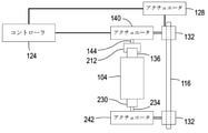
サブシステム108の一実施形態は、図1Bの印刷ヘッドとは反対の観点から示されている。サブシステム108は、部材116を受け取る一対のスリーブ132を含む。スリーブ132の少なくとも1つはアクチュエータ128に動作可能に接続され、コントローラ124はアクチュエータ128を動作させて、サブシステム108を部材116に沿って双方向に移動させることができる。この双方向移動は、プロセス方向の移動と呼ばれる。図示の構成は、アクチュエータ140及び242を部材116からオフセットする。印刷ヘッド118は、部材116の長手方向軸からプロセス横断方向にオフセットされて、印刷ヘッドがサブシステム108によって保持されたオブジェクト104に向かってマーキング材料を射出することを可能にする。同様に、UV硬化装置120は、プロセス横断方向にオフセットされて、UV硬化装置がUV光をオブジェクト104上の画像に向けることができ、オブジェクト上のUV硬化性材料を硬化させることを可能にする。アクチュエータ140は、スリーブ132のうちの1つに機械的に接続され、コントローラ124に動作可能に接続される。ホルダ212は、アクチュエータ140の出力軸144に取り付けられている。ホルダ212は、以下でより詳細に説明されるように、アクチュエータ140がコントローラ124によって動作されて、オブジェクト104を回転させるときに、オブジェクト104の一部136を把持及び保持するように構成される。アクチュエータ242の出力軸234に回転可能に取り付けられた延長部230は、オブジェクト104の下部を支持する。アクチュエータ242はスリーブ132に接続され、アクチュエータ242はその出力軸234をオブジェクト104に向かって、またはそれから離れて変位させ、オブジェクト104が、以下に詳細に説明するように、オブジェクト回転サブシステム108に装着されること及びそれから取り外されることを可能にする。
One embodiment of the
図2は、印刷システム100で使用され得るオブジェクト回転サブシステム108の一実施形態を示す。本文書で使用される際、「サブシステム」という用語は、より大きなシステム内で特定の機能を実行するように動作する2つ以上の構成要素を指す。図2には示されていないが、図1Bを参照して上述したように、コントローラ124は、アクチュエータ128を動作させて、スリーブ132及びサブシステム108をプロセス方向において印刷ヘッドアレイ112及びUV硬化装置120を通過して移動させる。図1B及び図2に示すように、サブシステム108のアクチュエータ140は、ホルダ212が取り付けられた出力軸144を有する電気モータとすることができる。図2は、電気スイッチ220を介して電源216に電気的に接続されたアクチュエータ140をさらに示す。コントローラ124は、電気スイッチ220に動作可能に接続されて、コントローラがスイッチ220を動作させ、アクチュエータ140を電力に選択的に接続することを可能にする。オブジェクト104の少なくとも一部136がホルダ212内に固定されると、コントローラ124は、スイッチ220を介してアクチュエータ140を動作させて、オブジェクトを回転させることができる。オブジェクト回転サブシステム108がアレイ112(図1A)内の印刷ヘッド118を通過して移動させるとき、オブジェクトの回転は、オブジェクトの一部または全部の外周を1つ以上の印刷ヘッドによって印刷することを可能にする。図2に示す一実施形態では、ロータリエンコーダ224はアクチュエータ140の出力軸の隣に位置付けされ、コントローラ124が、軸144の位置を示すエンコーダによって生成される電気信号を受信することを可能にする。コントローラ124は、コントローラがエンコーダ224からの電気信号を処理し、印刷ヘッド118に面するオブジェクト104の外周部分を識別することを可能にするソフトウェアを伴って構成され、画像の一部をオブジェクト上に印刷することができる。代替の実施形態では、アクチュエータ140はステッパモータであり、コントローラ124は、ホルダ及びオブジェクトを回転させるためにアクチュエータに送信されるパルスを参照して、ホルダ212によって把持されたオブジェクトの位置を識別する。この実施形態では、コントローラが印刷ヘッドに面するオブジェクト表面の一部を識別できるようにエンコーダは必要とされない。
FIG. 2 shows an embodiment of the
ホルダ212は、既知のコレットチャック、3つの爪チャック、被印刷オブジェクトの先端に位置する構造を把持するように構成されたカラー、粒状材料ホルダなどであってもよい。本文書で使用される際、「ホルダ」とは、被印刷オブジェクトを固定するように構成された任意の装置を意味する。本文書で使用される際、「カラー」及び「チャック」という用語は、開口部を有する平面部材と、開口部のサイズを変化させて所定の向きのオブジェクトを選択的に固定する少なくとも1つの可動部材を意味する。チャックは、第1の方向に回転して、チャックの少なくとも1つの可動部材をチャック内の開口部内に前進させて、既知の方法でオブジェクトを固定することができる。チャックの回転を逆にすると、オブジェクトをカラーから解放する。チャックの別の実施形態では、チャックの可動部材は、チャック内の開口部の中央で一緒になり、チャックの第1の方向への回転は、部材を開口部の外周方向に移動させ、その部材をボトルの口のようなオブジェクトの開口部に挿入することができ、第1の方向の回転は、部材を、印刷オブジェクトを保持するためにオブジェクトの開口部の外周に対して付勢する。チャックの回転を逆にすることにより、開口部の中心に部材が集まり、オブジェクトを除去することができるようにオブジェクト開口部の外周に対する圧力を低減する。本文書で使用される際、「粒状材料ホルダ」という用語は、空気排出及び空気加圧源に流体的に接続された内部を有し、粒状材料の粒間の空気を除去して、容器を変形させてオブジェクトを固定し、オブジェクトの一部を解放するように粒間に空気を付勢することを可能にする、粒状材料で充填された柔軟な容器を意味する。
The
図2に示すように、オブジェクト回転サブシステム108内のアクチュエータ242の出力軸234は、オブジェクト104の下部と係合する延長部230を含む。延長部230は、ベアリングなどによって出力軸234に回転可能に取り付けられている。アクチュエータ140がオブジェクト104を回転させると、延長部230は、出力軸234の周りを回転してオブジェクトを回転させる。出力軸234は、出力軸234を垂直方向に双方向に移動させるように構成されたアクチュエータ242に動作可能に接続されている。コントローラ124は、アクチュエータ242に動作可能に接続され、アクチュエータ242を動作させて、延長部230がホルダ212によって他端部に保持されたオブジェクト104の下部表面に係合する位置に延長部230を移動させる。この位置において、延長部230は、印刷中にオブジェクト104を支持するのを助け、アクチュエータ140が出力軸144及びオブジェクト104を回転させると自由に回転する。アクチュエータ242の動作は、異なる長さのオブジェクトを収容するために、延長部230とホルダ212との間の距離を変化させる。オブジェクトの印刷が完了し、サブシステム108がその開始位置に戻ると、ホルダ212が動作して、オブジェクト104の一端が解放され、アクチュエータ242が動作して、延長部230を下降させ、オブジェクト104をサブシステム108から回収し得る。
As shown in FIG. 2, the
プリンタ100を動作させるためのプロセスを図3に示す。このプロセスの説明では、プロセスが何らかのタスクまたは機能を実行しているという記述は、タスクまたは機能を実行するためにデータを操作するか、またはプリンタ内の1つ以上の構成要素を動作させるために、コントローラまたはプロセッサに動作可能に接続された非一時的なコンピュータ可読記憶媒体に格納されたプログラムされた命令を実行するコントローラまたは汎用プロセッサを指す。上述したコントローラ124は、そのようなコントローラまたはプロセッサとすることができる。代替的に、コントローラは、複数のプロセッサ及び関連する回路ならびに構成要素で実装することができ、その各々は、本明細書で説明する1つ以上のタスクまたは機能を形成するように構成される。付加的に、この方法のステップは、図に示される順序またはプロセスが記述される順序にかかわらず、任意の実行可能な時間順に実行されてもよい。
The process for operating the
図3Aは、回転オブジェクトサブシステム108のいずれかの実施形態で上述した印刷オブジェクトの回転を実装するプロセスのフロー図である。プロセス300は、ホルダ212がサブシステム108内にオブジェクト104を固定するように動作し、アクチュエータ242が動作して、延長部230を有するオブジェクトの下部を支持して開始する(ブロック304)。コントローラ124は、コントローラが印刷ヘッドを動作させて、印刷ヘッドに面するオブジェクトのセクタを印刷する(ブロック308)とき、アレイ112内の印刷ヘッド118によってオブジェクト104を移動させるためにアクチュエータ128を動作させる。オブジェクトの別のセクタが印刷される場合(ブロック312)、コントローラ124は、オブジェクトがアレイ112内の最後の印刷ヘッド118を通過して印刷される次のセクタまで通過した後に、(ブロック316)アクチュエータ140を動作させて、オブジェクト104を回転させる。コントローラ124は、アクチュエータ128を動作させて、オブジェクトを印刷ヘッド118によって反対の方向に移動させ、印刷ヘッドが印刷ヘッドに面するセクタを印刷できるようにする(ブロック312)。オブジェクトを回転させ、次にオブジェクトを印刷ヘッドを通過して通過させるこのプロセスは、印刷を必要とするオブジェクト外周上の全てのセクタが印刷されるまで継続される。その時点で、コントローラ124は、アクチュエータ128を動作させて、オブジェクトをその開始位置に戻し(ブロック320)、そこで、それをホルダ212から解放することができる(ブロック324)。
FIG. 3A is a flow diagram of a process that implements the rotation of the print object described above in any embodiment of the
回転オブジェクトサブシステム108のいずれかの実施形態によって保持されたオブジェクトの印刷を実装する代替プロセスのフロー図を図3Bに示す。プロセス350は、ホルダ212がサブシステム108内にオブジェクト104を固定するように動作し、アクチュエータ242が動作して、延長部230を有するオブジェクトの下部を支持して開始する(ブロック354)。コントローラ124はアクチュエータ128を動作させて、アレイ112内の印刷ヘッド118のうちの1つとは反対のオブジェクトを停止させる(ブロック358)。オペレータは、オブジェクトの印刷に先立って、オブジェクト構成を識別するデータを入力することができる。オブジェクトが非円筒形である場合(ブロック362)、印刷ヘッドとは反対のオブジェクトセクタが印刷され(ブロック366)、プロセスは別のオブジェクトセクタが印刷されるかどうかを判定する(ブロック370)。ブロック366の処理によって実行される印刷は、画像の垂直高さが、セクタを印刷するために現在使用されている印刷ヘッドのイジェクタアレイの高さよりも大きい場合、セクタを印刷するために、わずかな増分だけオブジェクトを垂直方向に移動させることを含むことができる。別のセクタが印刷される場合、コントローラ124は、オブジェクトを回転させる前にセンサ142からの信号を参照して、アクチュエータ138を動作させて、アレイ112、サブシステム108、またはその両方を互いに移動させる(ブロック374)。オブジェクト及びアレイが適切な距離だけ分離されて、アレイに当たることなくオブジェクトの回転を可能にすると、オブジェクトは回転され(ブロック378)、アクチュエータ138を動作させるコントローラ124によってオブジェクトは非円筒形オブジェクトの別のセクタを印刷するのに適切な距離に戻る(ブロック382)。このセクタが印刷され(ブロック366)、プロセスは、印刷ヘッドと反対のオブジェクトの外周のセクタが全て印刷されるまで継続される(ブロック370)。現在の周囲のセクタの全てが印刷されると、プロセスは、周囲が別の印刷ヘッドで印刷されるかどうかを判定する(ブロック386)。そうである場合、ブロック358~382のプロセスが繰り返されて、周囲を別の印刷ヘッドで印刷する。周囲が全ての印刷ヘッドによって印刷されると、そのオブジェクトはその開始位置に戻され(ブロック390)、ホルダから解放される(ブロック394)。オブジェクトが円筒形の場合、印刷ヘッドに当たることなく回転できる。この状況では、オブジェクトが停止した第1の印刷ヘッドは、オブジェクトが回転されるときに外周を印刷するように動作する(ブロック396)。ブロック396の処理によって実行される印刷は、画像の垂直高さが、セクタを印刷するために現在使用されている印刷ヘッドのイジェクタアレイの高さよりも大きい場合、セクタを印刷するために、わずかな増分だけオブジェクトを垂直方向に移動させることを含むことができる。外周が別の印刷ヘッドで印刷される場合(ブロック386)、オブジェクトは印刷ヘッドの反対に移動され(ブロック358)、印刷ヘッドで印刷されている間に回転される(ブロック396)。このプロセスは、全ての印刷ヘッドが外周を印刷するまで継続する。その時点で、オブジェクトはその開始位置に戻され(ブロック390)、ホルダから解放される(ブロック394)。
FIG. 3B shows a flow diagram of an alternative process that implements printing of objects held by any embodiment of the
図3A及び図3Bのプロセスにおけるオブジェクト104の回転は、図4に示されているように、第1の印刷部分から所定の距離だけ離れている印刷のための外周または周囲の別の部分を提示することができる。したがって、ハンドルのような表面の突起または窪みを避けるために、オブジェクトの外周または周囲の異なるセクタを印刷することができ、円筒形オブジェクトは、ブロック396において、図3Bのプロセスによって回転されて図5に示すように、オブジェクト104の全部または大部分の周りに連続的な画像を印刷することを可能にする。図3Aのプロセスでは、オブジェクトが印刷ヘッドアレイを通った後に発生するオブジェクトの回転は、印刷のための非連続セクタまたはオブジェクトの構成に関係ない印刷のための連続セクタのいずれかを提示することができる。
The rotation of the
上記で開示された装置及び他の特徴、ならびに機能またはそれらの代替物の変形は、多くの他の異なるシステムまたはアプリケーションに望ましく組み合わされ得ることが理解されるであろう。例えば、上述の実施形態は垂直構成で示されているが、印刷システム及びオブジェクト回転サブシステムは、プリンタを介してオブジェクトを他の方向に移動するように構成することができる。当業者であれば、現在予知しない、または予期しない種々の代替、変更、変形、または改良を後で行うことができ、これらもまた添付の特許請求の範囲によって包含されるものとする。 It will be appreciated that the devices and other features disclosed above, as well as variations of functions or their alternatives, can be desirablely combined with many other different systems or applications. For example, although the embodiments described above are shown in a vertical configuration, the printing system and object rotation subsystem can be configured to move the object in other directions through the printer. One of ordinary skill in the art may make various alternatives, changes, modifications, or improvements that are currently unforeseen or unexpected, which are also covered by the appended claims.
Claims (9)
少なくとも1つの印刷ヘッドであって、マーキング材料の液滴を射出するように構成された少なくとも1つの印刷ヘッドと、
第1の端部と第2の端部を有する部材であって、前記部材の前記第1の端部は前記第2の端部より高い位置にあり、前記少なくとも1つの印刷ヘッドは、前記部材と対向し、前記部材の前記第1の端部と前記第2の端部の間に位置している、部材と、
オブジェクトを保持するように、かつ前記第1の端部と前記第2の端部の間の前記部材に沿って移動させて前記少なくとも1つの印刷ヘッドを通過して前記オブジェクトを運び、前記少なくとも1つの印刷ヘッドがマーキング材料の液滴を前記オブジェクト上に射出することができるように構成されたオブジェクト回転サブシステムであって、
第1のアクチュエータと、
前記第1のアクチュエータに動作可能に接続されたホルダであって、前記オブジェクトの一部を把持するように構成されたホルダと、
出力軸を有する第2のアクチュエータと、
前記第2のアクチュエータの前記出力軸に回転可能に取り付けられた延長部であって、前記ホルダによって把持された前記オブジェクトの前記一部とは反対の前記オブジェクトの端部で前記オブジェクトの平らな表面を支持するように構成された延長部と、
前記第1のアクチュエータ及び前記第2のアクチュエータに動作可能に接続されたコントローラであって、前記第1のアクチュエータを動作させて、前記ホルダ及び前記ホルダによって把持された前記オブジェクトを回転させ、前記少なくとも1つの印刷ヘッドが、前記少なくとも1つの印刷ヘッドの幅よりも長い前記オブジェクトの外周の一部を印刷すること、並びに、前記第2のアクチュエータを動作させて、前記第2のアクチュエータの前記出力軸を伸ばして前記延長部を前記ホルダによって把持された前記オブジェクトの前記一部とは反対の前記オブジェクトの端部の前記平らな表面と係合させ、及び前記第2のアクチュエータの前記出力軸を縮めて前記ホルダが前記オブジェクトを解放した後に前記オブジェクトを支持して前記オブジェクトを前記ホルダから離すように移動させることを可能にするように構成されている、コントローラと、を備える、オブジェクト回転サブシステムと、を備える印刷システム。 It ’s a printing system.
With at least one printhead configured to eject droplets of marking material.
A member having a first end and a second end, wherein the first end of the member is higher than the second end, and the at least one print head is the member. And the member, which is located between the first end and the second end of the member.
The object is carried so as to hold the object and moved along the member between the first end and the second end and through the at least one print head to carry the object at least one. An object rotation subsystem configured to allow one printhead to eject droplets of marking material onto said object.
The first actuator and
A holder operably connected to the first actuator and configured to grip a portion of the object.
A second actuator with an output shaft and
An extension rotatably attached to the output shaft of the second actuator, the flat surface of the object at the end of the object opposite to the part of the object gripped by the holder. With an extension configured to support
A controller operably connected to the first actuator and the second actuator, the first actuator is operated to rotate the holder and the object held by the holder, at least. One printhead prints a portion of the outer circumference of the object that is longer than the width of the at least one printhead, and the second actuator is operated to operate the output shaft of the second actuator. To engage the extension with the flat surface at the end of the object opposite to the part of the object gripped by the holder, and retract the output shaft of the second actuator. With an object rotation subsystem comprising a controller configured to support the object and allow the object to be moved away from the holder after the holder has released the object. , A printing system.
前記第1のアクチュエータの出力軸の角変位を示す電気信号を生成するように構成されたロータリエンコーダをさらに備え、
前記コントローラが、前記ロータリエンコーダによって生成された前記電気信号を処理して、前記オブジェクトの表面の位置を識別するようにさらに構成される、請求項3に記載の印刷システム。 The object rotation subsystem
Further comprising a rotary encoder configured to generate an electrical signal indicating an angular displacement of the output shaft of the first actuator.
The printing system of claim 3, wherein the controller is further configured to process the electrical signal generated by the rotary encoder to identify the location of the surface of the object.
電源と、
前記電源及び前記第1のアクチュエータに動作可能に接続された電気スイッチと、を備え、
前記コントローラが、前記電気スイッチに動作可能に接続され、前記コントローラが、前記電気スイッチを動作させて、前記電源を前記第1のアクチュエータに選択的に接続するようにさらに構成される、請求項4に記載の印刷システム。 The object rotation subsystem
Power supply and
The power supply and the electric switch operably connected to the first actuator are provided.
4. The controller is operably connected to the electric switch, and the controller is further configured to operate the electric switch to selectively connect the power source to the first actuator. The printing system described in.
前記コントローラが、前記第3のアクチュエータに動作可能に接続され、前記コントローラが、前記オブジェクト回転サブシステムに接続された前記第3のアクチュエータを動作させて、前記部材に沿った両方向のプロセス方向において前記オブジェクト回転サブシステムを移動させるようにさらに構成される、請求項5に記載の印刷システム。 Further equipped with a third actuator operably connected to the object rotation subsystem,
The controller is operably connected to the third actuator, and the controller operates the third actuator connected to the object rotation subsystem to operate the third actuator in bidirectional process directions along the member. The printing system of claim 5, further configured to move an object rotation subsystem.
前記コントローラが、前記第4のアクチュエータに動作可能に接続され、前記コントローラが、前記第4のアクチュエータを動作させて、前記少なくとも1つの印刷ヘッドを前記オブジェクト回転サブシステムの前記ホルダによって把持された前記オブジェクトに向かって及びそれから離れるように移動させるようにさらに構成される、請求項6に記載の印刷システム。 A fourth actuator operably connected to the at least one printhead such that the at least one printhead is directed towards and away from the object gripped by the holder of the object rotation subsystem. Further equipped with a fourth actuator configured to move,
The controller is operably connected to the fourth actuator, and the controller operates the fourth actuator to grip the at least one printhead by the holder of the object rotation subsystem. The printing system of claim 6, further configured to move towards and away from the object.
前記コントローラが、前記センサに動作可能に接続され、前記コントローラが、前記第4のアクチュエータを動作させて、前記少なくとも1つの印刷ヘッドを、前記センサから受信した前記信号を参照して前記オブジェクト回転サブシステムの前記ホルダによって把持された前記オブジェクトに向かって及びそれから離れるように移動させるようにさらに構成される、請求項7に記載の印刷システム。 When the object rotation subsystem is positioned opposite to the at least one printhead, the signal corresponding to the distance between the at least one printhead and the object gripped by the holder of the object rotation subsystem. Further equipped with sensors configured to generate
The controller is operably connected to the sensor, and the controller operates the fourth actuator to allow the at least one printhead to reference the signal received from the sensor to the object rotation sub. 7. The printing system of claim 7, further configured to move towards and away from the object gripped by said holder of the system.
Applications Claiming Priority (2)
| Application Number | Priority Date | Filing Date | Title |
|---|---|---|---|
| US15/674,764 US10214026B1 (en) | 2017-08-11 | 2017-08-11 | System and method for rotating a three-dimensional (3D) object during printing of the object |
| US15/674,764 | 2017-08-11 |
Publications (3)
| Publication Number | Publication Date |
|---|---|
| JP2019034542A JP2019034542A (en) | 2019-03-07 |
| JP2019034542A5 JP2019034542A5 (en) | 2021-08-26 |
| JP6997684B2 true JP6997684B2 (en) | 2022-01-18 |
Family
ID=65084709
Family Applications (1)
| Application Number | Title | Priority Date | Filing Date |
|---|---|---|---|
| JP2018135418A Active JP6997684B2 (en) | 2017-08-11 | 2018-07-19 | A system and method for rotating a three-dimensional (3D) object while printing the object. |
Country Status (4)
| Country | Link |
|---|---|
| US (1) | US10214026B1 (en) |
| JP (1) | JP6997684B2 (en) |
| CN (1) | CN109383135A (en) |
| DE (1) | DE102018119352A1 (en) |
Families Citing this family (2)
| Publication number | Priority date | Publication date | Assignee | Title |
|---|---|---|---|---|
| US11110722B2 (en) | 2018-12-14 | 2021-09-07 | Xerox Corporation | System for directly printing fibrous objects with solid ink images |
| US11518085B2 (en) | 2020-07-31 | 2022-12-06 | Xerox Corporation | System and method for adjusting printing operations in a direct-to-object printer having limited drop size variation printheads |
Citations (5)
| Publication number | Priority date | Publication date | Assignee | Title |
|---|---|---|---|---|
| DE102010034780A1 (en) | 2010-08-18 | 2012-02-23 | Volker Till | Apparatus and method for printing on containers |
| DE102013214935A1 (en) | 2013-07-30 | 2015-02-05 | Krones Ag | Printing station and method for direct printing of containers |
| US20160221360A1 (en) | 2013-09-13 | 2016-08-04 | Till Gmbh | Printing press for printing three-dimensional objects |
| DE102015216026A1 (en) | 2015-08-21 | 2017-02-23 | Krones Ag | Direct printing machine and method for printing on containers with direct printing |
| JP2018176735A (en) | 2017-04-03 | 2018-11-15 | ゼロックス コーポレイションXerox Corporation | Object holder for direct-to-object printer |
Family Cites Families (32)
| Publication number | Priority date | Publication date | Assignee | Title |
|---|---|---|---|---|
| US7048651B2 (en) | 1998-10-06 | 2006-05-23 | Callaway Golf Company | Golf Ball |
| JP2000503920A (en) | 1996-01-26 | 2000-04-04 | テトラ ラバル ホールデイングス エ フイナンス ソシエテ アノニム | Method and apparatus for printing images on packaging materials |
| US6360656B2 (en) | 2000-02-28 | 2002-03-26 | Minolta Co., Ltd. | Apparatus for and method of printing on three-dimensional object |
| US20020097280A1 (en) | 2001-01-25 | 2002-07-25 | Bertram Loper | Apparatus and method of printing on a curved surface with an ink jet printer |
| US7120300B1 (en) | 2002-05-14 | 2006-10-10 | Sasken Communication Technologies Limited | Method for finding representative vectors in a class of vector spaces |
| AU2003207963A1 (en) | 2002-08-19 | 2004-03-03 | Creo Il. Ltd. | Continuous flow inkjet utilized for 3d curved surface printing |
| US6923115B1 (en) | 2003-11-19 | 2005-08-02 | Ross Clayton Litscher | Method, apparatus and system for printing on textured, nonplanar objects |
| US20050178279A1 (en) * | 2004-01-21 | 2005-08-18 | Josep Valls | Method and apparatus for printing an image on an irregular surface |
| US7210408B2 (en) * | 2004-12-30 | 2007-05-01 | Plastipak Packaging, Inc. | Printing plastic containers with digital images |
| DE102006001223A1 (en) * | 2006-01-10 | 2007-07-12 | Khs Ag | Apparatus for printing on bottles or similar containers |
| US20090256897A1 (en) | 2007-03-27 | 2009-10-15 | Michael Lane Polk | Object holder for printing multiple images |
| KR100813311B1 (en) * | 2007-11-05 | 2008-03-17 | 일리정공 주식회사 | Plotter capable of printing image on a body of revolution |
| KR20100098546A (en) | 2007-12-31 | 2010-09-07 | 엑사테크 엘.엘.씨. | Method for printing high quality images on curved substrates |
| MX2010014343A (en) | 2008-06-24 | 2011-02-21 | Plastipak Packaging Inc | Apparatus and method for printing on articles having a non-planar surface. |
| US8372726B2 (en) | 2008-10-07 | 2013-02-12 | Mc10, Inc. | Methods and applications of non-planar imaging arrays |
| EP2432639A4 (en) * | 2009-05-21 | 2013-05-29 | Inx Internat Ink Company | Apparatuses for printing on generally cylindrical objects and related methods |
| CN101954342A (en) | 2009-07-14 | 2011-01-26 | 鸿富锦精密工业(深圳)有限公司 | Method for printing paint on workpiece |
| DE202009018193U1 (en) * | 2009-09-30 | 2011-04-21 | Khs Gmbh | Device for treating packaging |
| CN201677576U (en) * | 2010-04-29 | 2010-12-22 | 纳百利装饰材料(深圳)有限公司 | Digital jet printing device for stereoscopic external surface |
| CN103781631B (en) * | 2011-09-02 | 2016-10-12 | Khs有限责任公司 | For processing the device of packaging article and for packing holding and the centering unit of article |
| DE102011086015A1 (en) | 2011-11-09 | 2013-05-16 | Krones Aktiengesellschaft | Method and apparatus for ink jet printing on curved object surfaces |
| DE102012005924A1 (en) | 2012-03-26 | 2013-09-26 | Khs Gmbh | Method and an arrangement for printing a surface |
| US9114282B2 (en) | 2012-05-30 | 2015-08-25 | Nike, Inc. | Game ball or other article of sports equipment printed with visible light-curable ink and method |
| US9321257B2 (en) * | 2013-04-04 | 2016-04-26 | Nike, Inc. | Cylinder with recessed portions for holding tubular articles for printing |
| US20160052147A1 (en) | 2014-08-19 | 2016-02-25 | GM Global Technology Operations LLC | Conformable magnetic holding device |
| DE102014218361A1 (en) * | 2014-09-12 | 2016-03-17 | Krones Ag | Apparatus and method for treating containers by direct printing and / or labeling |
| EP4056380B1 (en) * | 2014-10-21 | 2024-04-03 | Gen-Probe Incorporated | Method and apparatus for printing on an object having a curved surface |
| EP3106402B1 (en) * | 2015-06-16 | 2018-05-16 | Gea Procomac S.p.A. | Process and apparatus for closing and printing/labelling a container |
| US9659202B2 (en) | 2015-08-13 | 2017-05-23 | International Business Machines Corporation | Printing and extraction of 2D barcode on 3D objects |
| CN106183416A (en) * | 2016-07-26 | 2016-12-07 | 北京美科艺数码科技发展有限公司 | A kind of inkjet-printing device |
| CN106427209A (en) * | 2016-08-31 | 2017-02-22 | 广州市申发机电有限公司 | Automatic four-color twelve-station complex curved surface digital rotation printing machine |
| CN106739542A (en) * | 2017-01-22 | 2017-05-31 | 广州市申发机电有限公司 | A kind of full-automatic rapidly and efficiently surface of revolution Digital ink-jet printer |
-
2017
- 2017-08-11 US US15/674,764 patent/US10214026B1/en active Active
-
2018
- 2018-07-19 JP JP2018135418A patent/JP6997684B2/en active Active
- 2018-07-20 CN CN201810810502.9A patent/CN109383135A/en active Pending
- 2018-08-08 DE DE102018119352.1A patent/DE102018119352A1/en active Pending
Patent Citations (5)
| Publication number | Priority date | Publication date | Assignee | Title |
|---|---|---|---|---|
| DE102010034780A1 (en) | 2010-08-18 | 2012-02-23 | Volker Till | Apparatus and method for printing on containers |
| DE102013214935A1 (en) | 2013-07-30 | 2015-02-05 | Krones Ag | Printing station and method for direct printing of containers |
| US20160221360A1 (en) | 2013-09-13 | 2016-08-04 | Till Gmbh | Printing press for printing three-dimensional objects |
| DE102015216026A1 (en) | 2015-08-21 | 2017-02-23 | Krones Ag | Direct printing machine and method for printing on containers with direct printing |
| JP2018176735A (en) | 2017-04-03 | 2018-11-15 | ゼロックス コーポレイションXerox Corporation | Object holder for direct-to-object printer |
Also Published As
| Publication number | Publication date |
|---|---|
| US20190047297A1 (en) | 2019-02-14 |
| US10214026B1 (en) | 2019-02-26 |
| CN109383135A (en) | 2019-02-26 |
| DE102018119352A1 (en) | 2019-02-14 |
| JP2019034542A (en) | 2019-03-07 |
Similar Documents
| Publication | Publication Date | Title |
|---|---|---|
| CN110167724B (en) | Apparatus and method for processing object | |
| JP6498010B2 (en) | Device for printing on the curved surface of an object | |
| JP3194775U (en) | Machine for printing on 3D objects by inkjet method | |
| US7967405B2 (en) | Methods and apparatus for image transfer | |
| JP6391506B2 (en) | Printer and device | |
| JP6747831B2 (en) | Object surface printing device | |
| JP6997684B2 (en) | A system and method for rotating a three-dimensional (3D) object while printing the object. | |
| JP6336936B2 (en) | System for detecting inoperable inkjets during printing of a three-dimensional object using an optical sensor and a reversible thermal substrate | |
| JP2015196384A5 (en) | Printer and device | |
| JP5656312B2 (en) | Three-dimensional printer and control method thereof | |
| JP7032985B2 (en) | A system that transports objects from a nested stack of objects to the printer for printing | |
| JP2013188647A (en) | Printing device | |
| JP6892804B2 (en) | Systems and methods for printing on three-dimensional (3D) curved objects | |
| US10226951B1 (en) | System and method for pivoting a printhead in a direct-to-object printer during printing of an object | |
| US10328632B2 (en) | Modular system for detecting inoperative ejectors in three-dimensional object printers | |
| JP6466215B2 (en) | A system that detects inoperable inkjets in a print head that ejects transparent ink using a thermal substrate. | |
| JP2020062877A (en) | System and method for printing on three-dimensional objects with ultraviolet curable inks in direct-to-object printer | |
| JP2019034542A5 (en) | ||
| JP2015196381A5 (en) | ||
| US10682843B2 (en) | System and method for indexing a three-dimensional (3D) object during printing of the object | |
| EP4159453A2 (en) | System, method and apparatus of applying, with a printhead of a printing system, ink to a substrate based on a distance the printhead has moved |
Legal Events
| Date | Code | Title | Description |
|---|---|---|---|
| RD02 | Notification of acceptance of power of attorney |
Free format text: JAPANESE INTERMEDIATE CODE: A7422 Effective date: 20180802 |
|
| RD04 | Notification of resignation of power of attorney |
Free format text: JAPANESE INTERMEDIATE CODE: A7424 Effective date: 20181019 |
|
| RD03 | Notification of appointment of power of attorney |
Free format text: JAPANESE INTERMEDIATE CODE: A7423 Effective date: 20210226 |
|
| RD04 | Notification of resignation of power of attorney |
Free format text: JAPANESE INTERMEDIATE CODE: A7424 Effective date: 20210409 |
|
| A521 | Written amendment |
Free format text: JAPANESE INTERMEDIATE CODE: A523 Effective date: 20210714 |
|
| A621 | Written request for application examination |
Free format text: JAPANESE INTERMEDIATE CODE: A621 Effective date: 20210714 |
|
| A871 | Explanation of circumstances concerning accelerated examination |
Free format text: JAPANESE INTERMEDIATE CODE: A871 Effective date: 20210714 |
|
| A131 | Notification of reasons for refusal |
Free format text: JAPANESE INTERMEDIATE CODE: A131 Effective date: 20210915 |
|
| A521 | Written amendment |
Free format text: JAPANESE INTERMEDIATE CODE: A523 Effective date: 20211029 |
|
| TRDD | Decision of grant or rejection written | ||
| A01 | Written decision to grant a patent or to grant a registration (utility model) |
Free format text: JAPANESE INTERMEDIATE CODE: A01 Effective date: 20211117 |
|
| A61 | First payment of annual fees (during grant procedure) |
Free format text: JAPANESE INTERMEDIATE CODE: A61 Effective date: 20211217 |
|
| R150 | Certificate of patent or registration of utility model |
Ref document number: 6997684 Country of ref document: JP Free format text: JAPANESE INTERMEDIATE CODE: R150 |