JP7032985B2 - A system that transports objects from a nested stack of objects to the printer for printing - Google Patents
A system that transports objects from a nested stack of objects to the printer for printing Download PDFInfo
- Publication number
- JP7032985B2 JP7032985B2 JP2018082675A JP2018082675A JP7032985B2 JP 7032985 B2 JP7032985 B2 JP 7032985B2 JP 2018082675 A JP2018082675 A JP 2018082675A JP 2018082675 A JP2018082675 A JP 2018082675A JP 7032985 B2 JP7032985 B2 JP 7032985B2
- Authority
- JP
- Japan
- Prior art keywords
- spindle
- article
- stack
- printing system
- conveyor
- Prior art date
- Legal status (The legal status is an assumption and is not a legal conclusion. Google has not performed a legal analysis and makes no representation as to the accuracy of the status listed.)
- Active
Links
Images


Classifications
-
- B—PERFORMING OPERATIONS; TRANSPORTING
- B41—PRINTING; LINING MACHINES; TYPEWRITERS; STAMPS
- B41J—TYPEWRITERS; SELECTIVE PRINTING MECHANISMS, i.e. MECHANISMS PRINTING OTHERWISE THAN FROM A FORME; CORRECTION OF TYPOGRAPHICAL ERRORS
- B41J11/00—Devices or arrangements of selective printing mechanisms, e.g. ink-jet printers or thermal printers, for supporting or handling copy material in sheet or web form
- B41J11/007—Conveyor belts or like feeding devices
-
- B—PERFORMING OPERATIONS; TRANSPORTING
- B41—PRINTING; LINING MACHINES; TYPEWRITERS; STAMPS
- B41J—TYPEWRITERS; SELECTIVE PRINTING MECHANISMS, i.e. MECHANISMS PRINTING OTHERWISE THAN FROM A FORME; CORRECTION OF TYPOGRAPHICAL ERRORS
- B41J25/00—Actions or mechanisms not otherwise provided for
- B41J25/001—Mechanisms for bodily moving print heads or carriages parallel to the paper surface
-
- B—PERFORMING OPERATIONS; TRANSPORTING
- B41—PRINTING; LINING MACHINES; TYPEWRITERS; STAMPS
- B41J—TYPEWRITERS; SELECTIVE PRINTING MECHANISMS, i.e. MECHANISMS PRINTING OTHERWISE THAN FROM A FORME; CORRECTION OF TYPOGRAPHICAL ERRORS
- B41J29/00—Details of, or accessories for, typewriters or selective printing mechanisms not otherwise provided for
- B41J29/38—Drives, motors, controls or automatic cut-off devices for the entire printing mechanism
-
- B—PERFORMING OPERATIONS; TRANSPORTING
- B41—PRINTING; LINING MACHINES; TYPEWRITERS; STAMPS
- B41J—TYPEWRITERS; SELECTIVE PRINTING MECHANISMS, i.e. MECHANISMS PRINTING OTHERWISE THAN FROM A FORME; CORRECTION OF TYPOGRAPHICAL ERRORS
- B41J3/00—Typewriters or selective printing or marking mechanisms characterised by the purpose for which they are constructed
- B41J3/407—Typewriters or selective printing or marking mechanisms characterised by the purpose for which they are constructed for marking on special material
- B41J3/4073—Printing on three-dimensional objects not being in sheet or web form, e.g. spherical or cubic objects
-
- B—PERFORMING OPERATIONS; TRANSPORTING
- B41—PRINTING; LINING MACHINES; TYPEWRITERS; STAMPS
- B41J—TYPEWRITERS; SELECTIVE PRINTING MECHANISMS, i.e. MECHANISMS PRINTING OTHERWISE THAN FROM A FORME; CORRECTION OF TYPOGRAPHICAL ERRORS
- B41J3/00—Typewriters or selective printing or marking mechanisms characterised by the purpose for which they are constructed
- B41J3/54—Typewriters or selective printing or marking mechanisms characterised by the purpose for which they are constructed with two or more sets of type or printing elements
-
- B—PERFORMING OPERATIONS; TRANSPORTING
- B65—CONVEYING; PACKING; STORING; HANDLING THIN OR FILAMENTARY MATERIAL
- B65G—TRANSPORT OR STORAGE DEVICES, e.g. CONVEYORS FOR LOADING OR TIPPING, SHOP CONVEYOR SYSTEMS OR PNEUMATIC TUBE CONVEYORS
- B65G59/00—De-stacking of articles
- B65G59/10—De-stacking nested articles
-
- B—PERFORMING OPERATIONS; TRANSPORTING
- B65—CONVEYING; PACKING; STORING; HANDLING THIN OR FILAMENTARY MATERIAL
- B65G—TRANSPORT OR STORAGE DEVICES, e.g. CONVEYORS FOR LOADING OR TIPPING, SHOP CONVEYOR SYSTEMS OR PNEUMATIC TUBE CONVEYORS
- B65G2201/00—Indexing codes relating to handling devices, e.g. conveyors, characterised by the type of product or load being conveyed or handled
- B65G2201/02—Articles
-
- B—PERFORMING OPERATIONS; TRANSPORTING
- B65—CONVEYING; PACKING; STORING; HANDLING THIN OR FILAMENTARY MATERIAL
- B65G—TRANSPORT OR STORAGE DEVICES, e.g. CONVEYORS FOR LOADING OR TIPPING, SHOP CONVEYOR SYSTEMS OR PNEUMATIC TUBE CONVEYORS
- B65G2814/00—Indexing codes relating to loading or unloading articles or bulk materials
- B65G2814/03—Loading or unloading means
- B65G2814/0301—General arrangements
- B65G2814/0308—Destacking devices
-
- B—PERFORMING OPERATIONS; TRANSPORTING
- B65—CONVEYING; PACKING; STORING; HANDLING THIN OR FILAMENTARY MATERIAL
- B65G—TRANSPORT OR STORAGE DEVICES, e.g. CONVEYORS FOR LOADING OR TIPPING, SHOP CONVEYOR SYSTEMS OR PNEUMATIC TUBE CONVEYORS
- B65G59/00—De-stacking of articles
- B65G59/10—De-stacking nested articles
- B65G59/107—De-stacking nested articles by means of rotary devices or endless elements
Description
本開示は、一般に、3次元(3D)オブジェクトへの印刷のためのシステムに関し、より具体的には、オブジェクトのネスト化されたスタック(重ねられた物品の積み重ね)から除去されたオブジェクトへの印刷のためのシステムに関する。 The present disclosure generally relates to a system for printing on three-dimensional (3D) objects, and more specifically, printing on objects removed from a nested stack of objects. Regarding the system for.
商業用物品印刷は、通常、物品の製造中に行われる。例えば、ボール表皮は、ボールが完成して膨張される前にパターン又はロゴが印刷される。したがって、例えば、潜在的な製品の顧客が複数の専門家又は大学のチームをサポートする領域において、製品をカスタマイズする配布サイトなどの非製造の確立は、領域に続いて様々なチームのロゴが付された製品の在庫を維持する必要がある。在庫を維持するために異なるロゴ毎に正確な数の製品を注文することは問題になり得る。 Commercial article printing is usually done during the manufacture of the article. For example, the ball skin is printed with a pattern or logo before the ball is completed and inflated. So, for example, in areas where potential product customers support multiple professional or university teams, non-manufacturing establishments such as distribution sites that customize products carry various team logos following the area. It is necessary to maintain the inventory of the products that have been made. Ordering the exact number of products for each different logo to maintain inventory can be problematic.
非製造直販店においてこれらの問題に対処する1つの方法は、印刷されていないバージョンの製品を保管し、配布サイトにおいてそれらにパターン又はロゴを印刷することである。3次元物体上に画像コンテンツを適用するために2次元(2D)媒体印刷技術などの公知の印刷技術を適応することは困難である。特に、プラスチックカップなどの場合のように、オブジェクトが格納のためにスタックされた配置においてネスト化されている場合に困難が生じる。一度に1つのオブジェクトが印刷のためにオブジェクトのスタックされた構成から除去される必要があり、顧客がいくつかのカスタムパターンによって印刷された2つ又は4つのオブジェクトのみを必要とするため、印刷されることになるオブジェクトの実行は短くてもよい。したがって、ネスト化された3Dオブジェクトを印刷することができる非製造環境において動作されることが可能な印刷システムは未知であるが望ましい。 One way to address these issues in non-manufacturing retailers is to store unprinted versions of the product and print patterns or logos on them at the distribution site. It is difficult to apply known printing techniques such as two-dimensional (2D) medium printing techniques to apply image content onto a three-dimensional object. Difficulties arise especially when objects are nested in a stacked arrangement for storage, such as in the case of plastic cups and the like. Printed because one object at a time needs to be removed from the stacked configuration of objects for printing and the customer only needs two or four objects printed by some custom patterns. The execution of the resulting object may be short. Therefore, a printing system capable of operating in a non-manufacturing environment capable of printing nested 3D objects is unknown but desirable.
新たな印刷システムは、一度に1つのオブジェクトをネスト化された3次元(3D)オブジェクトの表面に印刷するように構成されている。印刷システムは、複数の印刷ヘッドにおける各印刷ヘッドがマーキング材料を吐出するように構成された複数の印刷ヘッドと、複数の印刷ヘッドに向かってネスト化されたオブジェクトのスタックを移動させるように構成され、複数の印刷ヘッドに最も近いオブジェクトを除き、ネスト化されたオブジェクトのスタックにおける各オブジェクトの一部と係合するように部材から延在する複数の突起を有する部材を含むコンベアと、往復移動のために構成されたスピンドルと、オブジェクトを係合し且つ複数の印刷ヘッドに対向する位置にオブジェクトを移動させるように、アクチュエータが複数の印刷ヘッドに最も近いネスト化されたオブジェクトのスタックにおいてオブジェクトの開口内にスピンドルを移動させるのを可能とするようにスピンドルに動作可能に接続されたアクチュエータと、複数の印刷ヘッド、コンベア及びアクチュエータに動作可能に接続されたコントローラとを含む。コントローラは、印刷システム内のネスト化されたオブジェクトのスタックの少なくとも一部を移動させるようにコンベアを動作させ、オブジェクトを係合するように複数の印刷ヘッドに最も近いネスト化されたオブジェクトのスタックにおけるオブジェクトの開口内にスピンドルを移動させ、スタックからオブジェクトを除去し、複数の印刷ヘッドに対向する位置にオブジェクトを移動させるようにアクチュエータを動作させ、スピンドル上のオブジェクト上にマーキング材料を吐出するように複数の印刷ヘッドを動作させるように構成されている。 The new printing system is configured to print one object at a time on the surface of a nested three-dimensional (3D) object. The printing system is configured to move multiple printheads in multiple printheads, each of which is configured to eject marking material, and a stack of nested objects towards the multiple printheads. Reciprocating with a conveyor that contains a member with multiple protrusions extending from the member to engage a portion of each object in a stacked of nested objects, except for the object closest to multiple printheads. The actuator opens an object in a nested stack of objects closest to the multiple printheads so that the spindle is configured to engage the object and move the object to a position facing the multiple printheads. Includes an actuator operably connected to the spindle to allow movement of the spindle within, and a controller operably connected to multiple printheads, conveyors and actuators. The controller operates the conveyor to move at least a portion of the nested object stack in the printing system, in the nested object stack closest to multiple printheads to engage the objects. Move the spindle into the opening of the object, remove the object from the stack, move the actuator to move the object to a position facing multiple printheads, and eject the marking material onto the object on the spindle. It is configured to operate multiple printheads.
新たな印刷システムの他の実施形態は、複数の印刷ヘッドにおける各印刷ヘッドがマーキング材料を吐出するように構成された複数の印刷ヘッドと、複数の印刷ヘッドに向かってネスト化されたオブジェクトのスタックを移動させるように構成されたコンベアと、往復移動のために構成されたスピンドルと、オブジェクトを係合するようにアクチュエータが複数の印刷ヘッドに最も近いネスト化されたオブジェクトのスタックにおけるオブジェクトの開口であってコンベアの下方に配置された開口内にスピンドルを移動させるのを可能とするようにスピンドルに動作可能に接続されたアクチュエータと、第1の端部及び第2の端部を有する部材であって、部材の第1の端部が開口に配置され、第2の端部がスピンドルから解放されたオブジェクトを受けるように配置された部材と、複数の印刷ヘッド、コンベア及びアクチュエータに動作可能に接続されたコントローラとを含む。コントローラは、印刷システム内のネスト化されたオブジェクトのスタックの少なくとも一部を移動させるようにコンベアを動作させ、オブジェクトを係合するように複数の印刷ヘッドに最も近いネスト化されたオブジェクトのスタックにおけるオブジェクトの開口内にスピンドルを移動させ、スタックからオブジェクトを除去し、複数の印刷ヘッドに対向する位置にオブジェクトを移動させるようにアクチュエータを動作させ、オブジェクト上にマーキング材料を吐出するように複数の印刷ヘッドを動作させ、重力が部材の第1の端部に且つ部材の長さに沿って第2の端部まで且つ開口を介してオブジェクトを導くのを可能とするように、完成したオブジェクトの印刷に応答してスピンドルからオブジェクトを解放するようにアクチュエータを動作させるように構成されている。 Another embodiment of the new printing system is a stack of multiple printheads in which each printhead in the plurality of printheads is configured to eject marking material and objects nested towards the plurality of printheads. With a conveyor configured to move, a spindle configured for reciprocating movement, and an object opening in a stack of nested objects where the actuator is closest to multiple printheads to engage the object. A member having an actuator operably connected to the spindle and a first end and a second end to allow the spindle to be moved into an opening located below the conveyor. The first end of the member is placed in the opening and the second end is operably connected to the member placed to receive the object released from the spindle and to multiple printheads, conveyors and actuators. Including the controller. The controller operates the conveyor to move at least a portion of the nested object stack in the printing system, in the nested object stack closest to multiple printheads to engage the objects. Multiple prints to move the spindle into the object's opening, remove the object from the stack, move the actuator to a position facing multiple printheads, and eject marking material onto the object. Printing of the finished object so that the head is operated and gravity can guide the object to the first end of the member and along the length of the member to the second end and through the opening. It is configured to operate the actuator to release the object from the spindle in response to.
一度に1つのオブジェクトをネスト化された3次元(3D)オブジェクトの表面に印刷する新たな方法は、コンベア上のネスト化されたオブジェクトのスタックにおける隣接するオブジェクトの部分間においてコンベア内の部材上に突起を配置し且つ印刷システム内のネスト化されたオブジェクトのスタックの少なくとも一部を移動させるようにコントローラによってコンベアを動作させることと、オブジェクトを係合するように複数の印刷ヘッドに最も近いネスト化されたオブジェクトのスタックにおけるオブジェクトの開口内にスピンドルを移動させ、スタックからオブジェクトを除去し、複数の印刷ヘッドに対向する位置にオブジェクトを移動させるようにコントローラによってアクチュエータを動作させることと、スピンドル上のオブジェクト上にマーキング材料を吐出するようにコントローラによって複数の印刷ヘッドを動作させることとを含む。 A new way to print one object at a time onto the surface of a nested three-dimensional (3D) object is on a member in the conveyor in a portion of an adjacent object in a stack of nested objects on the conveyor. The controller operates the conveyor to place protrusions and move at least part of the stack of nested objects in the printing system, and nesting closest to multiple printheads to engage the objects. Move the spindle into the object's opening in the stack of objects, remove the object from the stack, and actuate the actuator by the controller to move the object to a position facing multiple printheads, and on the spindle. It involves operating multiple printheads by a controller to eject marking material onto an object.
一度に1つのオブジェクトをネスト化された3Dオブジェクトの表面に印刷する印刷システムの上述した態様及び他の特徴は、添付図面に関連して以下の詳細な説明において説明される。 The above-mentioned aspects and other features of a printing system that prints one object at a time on the surface of a nested 3D object are described in the following detailed description in connection with the accompanying drawings.
本実施形態の一般的な理解のために、図面が参照される。図面において、同様の参照符号は、同様の要素を示すために全体を通して使用されている。 The drawings are referenced for a general understanding of this embodiment. In the drawings, similar reference numerals are used throughout to indicate similar elements.
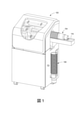
図1は、オブジェクトのネスト化されたスタック104からオブジェクトを取得し、取得されたオブジェクトの表面を印刷し、印刷されたオブジェクトをネスト化されたスタック108に排出するように構成された印刷システム100を示している。印刷システム100は、プリンタがオブジェクトの印刷のために図2に示されるように配置されるハウジング112を含む。図に示されるように、オブジェクトのネスト化されたスタックは、プラスチックカップのスタックであるが、ネスト化されたスタックは、ともにネスト化されることができる任意のオブジェクトとすることができ、それは、ネスト化されたスタックの一端に開口を提示する。ネスト化されたスタック104は、ハウジング112内を並進するためにコンベア116内に配置される。コンベア構造の詳細が以下に示される。
FIG. 1 shows a
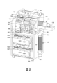
印刷システム100の内部構成要素が図2においてさらに詳細に示されている。シャトル120は、部材に沿って往復移動するために支持部材124に取り付けられている。固定ピッチネジ部材128は、シャトルを部材124に沿って双方向に移動させるようにアクチュエータがネジ部材128を双方向に回転させることができるように、シャトル120及びアクチュエータ122に動作可能に接続されている。シャトル120は、スピンドル136内で終端するロッド132に動作可能に接続されている。ロッド132は、スピンドル136を真空源140に空気圧で接続する導管を設けるように中空である。スピンドル136がスタック104に向かってシャトル120によって移動するのにともない、スピンドルは、スタック104におけるオブジェクトのネスト化されたスタック内の第1のオブジェクトの開口に入る。スピンドル136における1つ以上の孔は、真空源140が第1のオブジェクトの開口内から空気を引き出し、スピンドル136とオブジェクトの内部を嵌合するのを可能とする。
The internal components of the
アクチュエータ122がネジ部材128の回転を逆転させるように動作されると、シャトル120は、オブジェクトの両側の2つのアレイの印刷ヘッド144及び148に対向してオブジェクト140Aを位置決めするそのホームポジションに戻る。各アレイ144及び148は、4つの印刷ヘッドを有するが、より少ない又はより多くの印刷ヘッドが各アレイ内に構成されることができる。2つのアレイ144及び148における8つの印刷ヘッドは、それぞれ、インク供給源152Aから152Hに動作可能に接続されており、そのため、各印刷ヘッドは、システム100における1つのインク供給源のみによって個々に且つ独立して供給される。他の容器154は、印刷ヘッドのパージ動作からの廃インクの収集のためにプリンタにおける印刷ヘッドメンテナンスシステムに提供される。ロッド132に動作可能に接続されたアクチュエータ134は、ロッドを回転させ、そのため、スピンドル136は、オブジェクト140Aとともに回転する。コントローラ156は、最大8つの異なる色によってテキスト及びグラフィックスをオブジェクト140A上に印刷するように印刷ヘッドアレイ144及び148内の印刷ヘッドを動作させる。オブジェクト140Aが印刷された後、印刷ヘッドアレイ144及び148の下方に配置されたUVランプ168は、オブジェクトの表面上にUVインクが吐出されたオブジェクト140Aの表面を印刷するために印刷ヘッドのうちの1つ以上が使用されたときにオブジェクト140Aの表面に印刷されたインクを硬化させるようにコントローラ156によって動作される。硬化プロセスが完了すると、コントローラは、ロッド132及び136から真空源140を切断し、そのため、オブジェクトの重さは、スピンドル136からオブジェクトを除去する。いくつかの実施形態において、スピンドルが複数の印刷ヘッドに対向してオブジェクトを配置するように停止する位置は、機械的停止部158の手前にある。オブジェクトの印刷が完了すると、コントローラは、オブジェクトをスタックから離して移動させ続けるようにアクチュエータを動作させ、そのため、オブジェクトのエッジは、スピンドルからオブジェクトを解放する代替方式としてスピンドルからオブジェクトを押し出すように停止部に遭遇する。
When the
コンベア116が延在する開口160の下側部分は、ランプ164の一端に位置している。ランプ164の他端は、スピンドル136上に配置されたオブジェクト140Aの後端に向かって且つそれから離れるようにランプ164の他端を移動させるようにアクチュエータ166に動作可能に接続されている。オブジェクトがスピンドルから解放されると、重力は、硬化プロセス中にアクチュエータ166を動作させるコントローラ156によってその他端が持ち上げられたランプ164上にオブジェクトを導く。オブジェクトは、開口160の下側部分を通ってランプ164に沿って摺動し、ガイド172によって先に吐出されたオブジェクトと整列される。タブ176は、ガイド172内に排出されたオブジェクトのスタックを支持するようにハウジング112に取り付けられている。特定のテキスト及びグラフィックスパターンに対するオブジェクトの実行が印刷されて排出されると、スタックは、ガイド172から除去されることができ、そのため、オブジェクトのスタックは、テキスト及びグラフィックスの他のパターンによって印刷されることができる。
The lower portion of the
コンベア116は、図3においてより詳細に示されている。コンベア116は、フロア328を有するチャネル324を有するトレイ320を含む。支持ブラケット304は、1対のプーリ312まわりに同伴される無端ベルト308に動作可能に接続され、そのため、プーリの回転は、トレイ320のチャネル324内で支持ブラケット304を双方向に移動させる。プーリ312のうちの1つは、プーリの双方向回転移動のためにアクチュエータ332に動作可能に接続されている。支持ブラケット304は、オブジェクトのネスト化されたスタックにおける最後のオブジェクトの底部を支持する1対の突起336と、スタックにおける最後のオブジェクトの底部のウェル内に嵌合するセンタリングタブ340とを含む。湾曲した支持部材344は、スタックにおける最後のオブジェクトの外面の湾曲を収容し、部材344は、チャネル324の長手方向壁と平行なタブ348において終端する。センサ352は、印刷システム100内に配置されたコンベア116の端部に位置している。このセンサは、光センサ、磁気センサ、又は機械センサとすることができる。センサ352は、タブ348の存在を検出し、センサに対向するタブ348を示す電気信号を生成するように構成されている。コントローラ156は、タブ348がセンサに配置されたときにセンサによって生成された信号を受信するようにセンサ352に動作可能に接続されており、これに応答して、コントローラは、他のプーリ312までブラケット304を戻すようにプーリ312の回転方向を逆転させるようにアクチュエータ332を動作させ、そのため、他のオブジェクトのスタックは、ブラケット304に対してコンベア116内に装填されることができる。
図4は、オブジェクト104のネスト化されたスタックにおけるオブジェクトと無端ベルト308との間の相互作用を示している。無端ベルト308は、ワイヤ404の全長に沿って固定ピッチでワイヤ408によって螺旋状に巻回された無端ケーブル又はワイヤ404を含む。螺旋状に巻回されたワイヤ408は、図を容易とするためにワイヤ404の一端にのみ示されている。ワイヤ408のうち、オブジェクトのリップ412間に位置する部分は、スタックにおけるオブジェクトを保持するのを助ける。スピンドルがオブジェクトにおける開口に接触することができるコンベアの端部にスタックの端部にあるオブジェクト140Bが到達すると、ワイヤ408は、ワイヤ404を辿り、印刷システム100内のオブジェクト140Bのリップから離れる。それゆえに、ワイヤ408のない部分は、トレイ324における最も前方のオブジェクト140Bがスタック104から除去されるのを妨げない。スピンドル136(図2)がオブジェクト140Bの開口に入り、スピンドルにおける開口を通って流れる真空がオブジェクトの内部をスピンドルと係合するように引っ張ると、シャトル120及びスピンドル136の逆転移動は、スタックからオブジェクト140Bを除去する。しかしながら、螺旋状に巻回されたワイヤ408は、現在印刷されているオブジェクトが吐出されるとオブジェクトが除去されることができるように、アクチュエータ332がプーリ312を前進させてワイヤ408がもはや最前方のオブジェクトのリップに係合しなくなるまで、コンベア116内に残っているスタックにおける残りのオブジェクトの並進に十分な抵抗を提供する。
FIG. 4 shows the interaction between an object and the
上記開示された装置及び他の特徴、並びに機能の変形例、又はそれらの代替例は、多くの他の異なるシステム又はアプリケーションに望ましくは組み合わされることができることが理解される。現在は予期しない又は予測しない様々な代替例、変更例、変形例、又は改良例は、当業者によって後に行われることができ、以下の特許請求の範囲に包含されるようにも意図される。
It is understood that the devices and other features disclosed above, as well as variations in functionality, or alternatives thereof, can preferably be combined with many other different systems or applications. Various alternatives, modifications, variations, or improvements that are currently unexpected or unexpected can be made later by one of ordinary skill in the art and are also intended to be included in the claims below.
Claims (9)
複数の印刷ヘッドにおける各印刷ヘッドがマーキング材料を吐出するように構成された複数の印刷ヘッドと、
前記複数の印刷ヘッドに向かって重ねられた物品の積み重ねを移動させるように構成され、前記複数の印刷ヘッドに最も近い物品を除き、前記重ねられた物品の積み重ねにおける各物品の一部と係合するように部材から延在する複数の突起を有する部材を含むコンベアと、
往復移動のために構成されたスピンドルと、
前記物品を係合し且つ前記複数の印刷ヘッドに対向する位置に前記物品を移動させるように、アクチュエータが前記複数の印刷ヘッドに最も近い前記重ねられた物品の積み重ねにおいて前記物品の開口内に前記スピンドルを移動させるのを可能とするように前記スピンドルに動作可能に接続されたアクチュエータと、
前記複数の印刷ヘッド、前記コンベア及び前記アクチュエータに動作可能に接続されたコントローラであって、前記印刷システム内の前記重ねられた物品の積み重ねの少なくとも一部を移動させるように前記コンベアを動作させ、前記物品を係合するように前記複数の印刷ヘッドに最も近い前記重ねられた物品の積み重ねにおける前記物品の前記開口内に前記スピンドルを移動させ、前記積み重ねから前記物品を除去し、前記複数の印刷ヘッドに対向する位置に前記物品を移動させるように前記アクチュエータを動作させ、前記スピンドル上の前記物品上にマーキング材料を吐出するように前記複数の印刷ヘッドを動作させるように構成されたコントローラと
を備え、
前記コンベアの前記部材が、前記コンベア内の1対のプーリまわりに同伴される無端ワイヤであり、前記部材が、
突起を形成するように固定ピッチで前記無端ワイヤの長さまわりに螺旋状に巻回された第2のワイヤ
をさらに備える、印刷システム。 It ’s a printing system.
A plurality of print heads configured such that each print head in a plurality of print heads ejects marking material, and a plurality of print heads.
It is configured to move a stack of stacked articles towards the plurality of print heads and engages with a portion of each article in the stack of the stacked articles, except for the article closest to the plurality of print heads. A conveyor containing a member having a plurality of protrusions extending from the member so as to
With a spindle configured for reciprocating motion,
The actuator enters the opening of the article in the stack of the stacked articles closest to the plurality of print heads so as to engage the article and move the article to a position facing the plurality of print heads. An actuator operably connected to the spindle to allow the spindle to move, and
A controller operably connected to the plurality of print heads, the conveyor and the actuator to operate the conveyor to move at least a portion of the stack of stacked articles in the printing system. The spindle is moved into the openings of the articles in a stack of the stacked articles closest to the plurality of print heads to engage the articles, the articles are removed from the stack , and the plurality of prints are performed. A controller configured to operate the actuator to move the article to a position facing the head and to operate the plurality of print heads to eject marking material onto the article on the spindle. Prepare,
The member of the conveyor is an endless wire that is carried around a pair of pulleys in the conveyor, and the member is a member.
A printing system further comprising a second wire spirally wound around the length of the endless wire at a fixed pitch to form a protrusion.
前記複数の印刷ヘッドに最も近い前記コンベアの一方の端部に搭載されたセンサであって、前記ブラケットが前記センサに対向したことに応じて、電気信号を生成するように構成されたセンサを備え、
前記コントローラは、さらに、前記複数の印刷ヘッドから最も離れた前記プーリに前記ブラケットを移動させるよう、前記他のアクチュエータを反転動作させるように構成されている、請求項4に記載の印刷システム。 The conveyor further
A sensor mounted on one end of the conveyor closest to the plurality of print heads, comprising a sensor configured to generate an electrical signal in response to the bracket facing the sensor. ,
The printing system according to claim 4, wherein the controller is further configured to reverse the other actuator so as to move the bracket to the pulley farthest from the plurality of print heads.
第1の端部及び第2の端部を有する部材であって、重力が前記部材の前記第1の端部に且つ前記開口を介して前記物品を導くのを可能とするように、前記部材の前記第1の端部が前記開口に配置され、前記第2の端部が前記スピンドルから解放された物品を受けるように配置された部材と、
をさらに備えた、請求項5に記載の印刷システム。 With the opening placed under the conveyor,
A member having a first end and a second end, said member such that gravity allows gravity to guide the article to the first end of the member and through the opening. A member whose first end is arranged in the opening and whose second end is arranged to receive an article released from the spindle.
5. The printing system according to claim 5.
前記コントローラは、前記真空源に動作可能に接続され、さらに、前記スピンドルが前記複数の印刷ヘッドに最も近い前記物品の前記開口内にあることに応答して前記真空源を動作させ、前記複数の印刷ヘッドによる前記物品の印刷が完了したことに応答して前記真空源を動作停止させるように構成されている、請求項8に記載の印刷システム。 Further equipped with a vacuum source operably connected to the opening in the spindle,
The controller is operably connected to the vacuum source and further operates the vacuum source in response to the spindle being in the opening of the article closest to the plurality of printheads. The printing system of claim 8, wherein the vacuum source is configured to shut down in response to the completion of printing of the article by the print head.
Applications Claiming Priority (2)
| Application Number | Priority Date | Filing Date | Title |
|---|---|---|---|
| US15/591,263 | 2017-05-10 | ||
| US15/591,263 US10124614B1 (en) | 2017-05-10 | 2017-05-10 | System for conveying objects from a nested stack of objects to a printer for printing |
Publications (3)
| Publication Number | Publication Date |
|---|---|
| JP2018187926A JP2018187926A (en) | 2018-11-29 |
| JP2018187926A5 JP2018187926A5 (en) | 2021-09-09 |
| JP7032985B2 true JP7032985B2 (en) | 2022-03-09 |
Family
ID=62062959
Family Applications (1)
| Application Number | Title | Priority Date | Filing Date |
|---|---|---|---|
| JP2018082675A Active JP7032985B2 (en) | 2017-05-10 | 2018-04-24 | A system that transports objects from a nested stack of objects to the printer for printing |
Country Status (5)
| Country | Link |
|---|---|
| US (2) | US10124614B1 (en) |
| EP (1) | EP3401106B1 (en) |
| JP (1) | JP7032985B2 (en) |
| KR (1) | KR102320619B1 (en) |
| CN (1) | CN108859425B (en) |
Families Citing this family (5)
| Publication number | Priority date | Publication date | Assignee | Title |
|---|---|---|---|---|
| US11116352B2 (en) * | 2016-09-13 | 2021-09-14 | Kerry Luxembourg S.à.r.l. | Beverage preparation system |
| US10492626B2 (en) | 2017-12-12 | 2019-12-03 | Gpcp Ip Holdings Llc | Food service material dispensers, systems, and methods |
| US11752779B2 (en) * | 2017-12-12 | 2023-09-12 | Gpcp Ip Holdings Llc | Food service cup dispensers, systems, and methods |
| USD892875S1 (en) * | 2018-11-09 | 2020-08-11 | NEXA3D Inc. | Three-dimensional printer |
| US11110722B2 (en) * | 2018-12-14 | 2021-09-07 | Xerox Corporation | System for directly printing fibrous objects with solid ink images |
Citations (3)
| Publication number | Priority date | Publication date | Assignee | Title |
|---|---|---|---|---|
| JP2010522651A (en) | 2007-03-27 | 2010-07-08 | ストラ エンソ オーワイジェイ | Method and printer for producing printed cardboard containers |
| KR101200248B1 (en) | 2012-04-30 | 2012-11-09 | 현진제업주식회사 | Complex container manufacturing apparatus and method |
| JP2013123824A (en) | 2011-12-13 | 2013-06-24 | Tokan Kogyo Co Ltd | Container feeding device, and container feeding method |
Family Cites Families (41)
| Publication number | Priority date | Publication date | Assignee | Title |
|---|---|---|---|---|
| US1634566A (en) | 1923-04-03 | 1927-07-05 | Individual Drinking Cup Co | Cup dispenser |
| US2385267A (en) | 1942-01-21 | 1945-09-18 | Ata Mfg Company Inc | Cup-separating and dispensing machine |
| US2374168A (en) | 1942-06-22 | 1945-04-24 | Frostidrink Inc | Cup-dispensing mechanism |
| US2433736A (en) | 1943-09-16 | 1947-12-30 | Dixie Cup Co | Dispensing apparatus |
| US2497718A (en) | 1945-01-10 | 1950-02-14 | Westinghouse Electric Corp | Dispensing apparatus |
| US2517532A (en) | 1947-07-25 | 1950-08-08 | Dixie Cup Co | Dispensing machine for paper cups and the like |
| US2526014A (en) | 1948-12-08 | 1950-10-17 | Lily Tulip Cup Corp | Feeder for stacks of nested containers |
| US3098585A (en) | 1960-10-19 | 1963-07-23 | Giepen Associates Inc | Cup dispenser |
| US3032237A (en) | 1961-03-16 | 1962-05-01 | Drumstick Inc | Cup dispenser |
| US3506156A (en) | 1968-04-22 | 1970-04-14 | Vendo Co | Cup dropper with automatic control of replacement stack |
| US3661282A (en) * | 1970-03-04 | 1972-05-09 | Scott Paper Co | Method of continously moving containers through a treatment process |
| US3741410A (en) | 1971-03-24 | 1973-06-26 | Ekco Prod Inc | Separator |
| US3862702A (en) | 1974-01-21 | 1975-01-28 | American Can Co | Self-adjusting cup dispenser and method |
| US3977318A (en) * | 1974-08-14 | 1976-08-31 | Cohan Alvin M | Machine for simultaneous two image flexographic printing |
| US4180180A (en) | 1978-01-16 | 1979-12-25 | International Paper Company | Apparatus and method for automatically dispensing flexible containers |
| US4341375A (en) | 1981-05-04 | 1982-07-27 | Mario Romanin | Dual vise for skis and the like |
| US4418837A (en) | 1981-07-06 | 1983-12-06 | Owens-Illinois, Inc. | Automatic cup dispensing apparatus |
| US4531559A (en) | 1983-03-31 | 1985-07-30 | Glasgo Marion L | Clamp-on marking template and saw guide for making dovetail joints |
| US4943207A (en) * | 1987-05-04 | 1990-07-24 | Mobil Oil Corporation | Apparatus for denesting and feeding cartons to a conveyor |
| US4805758A (en) * | 1987-07-08 | 1989-02-21 | Van Dam Machine Corporation | Crossed turret cup feeder |
| US5064093A (en) * | 1990-04-16 | 1991-11-12 | W. A. Lane, Inc. | Product cup denester |
| US5622248A (en) | 1995-08-22 | 1997-04-22 | F & L Machinery Design, Inc. | Adjustable container feeding system for printing presses |
| US5682816A (en) * | 1996-04-18 | 1997-11-04 | Polytype America Corporation | Two stage feeding apparatus and method for feeding articles to a printing machine |
| US6623236B1 (en) * | 1998-12-23 | 2003-09-23 | Ipc, Inc. | Vacuum apparatus and method for denesting objects |
| US7011728B2 (en) | 2001-07-19 | 2006-03-14 | Berry Plastics Corporation | Container-labeling and-printing synchronization apparatus and process |
| JP2003132421A (en) * | 2001-10-23 | 2003-05-09 | Fuji Xerox Co Ltd | Automatic vending machine and automatic vending machine system |
| FR2856338B1 (en) | 2003-06-23 | 2005-09-16 | Dubuit Mach | MACHINE FOR PRINTING OBJECTS WITH IMPROVED PROTECTION FROM ULTRAVIOLET RADIATION. |
| US6913433B2 (en) * | 2003-07-01 | 2005-07-05 | Mark E. Riesterer | Denesting apparatus |
| US7153089B2 (en) * | 2003-09-12 | 2006-12-26 | Lockheed Martin Corporation | Storage device |
| US6907823B2 (en) * | 2003-10-21 | 2005-06-21 | Creo Inc. | Flexographic printing on containers |
| FR2875433B1 (en) | 2004-09-22 | 2006-11-24 | Overprint Ind Sarl | PROCESS FOR OVERPRINTING PACKAGES ALREADY PRINTED |
| US7735628B2 (en) * | 2004-12-17 | 2010-06-15 | Rennco Llc | Article transfer system |
| US20070284388A1 (en) * | 2006-06-12 | 2007-12-13 | Liao Benker P C | Device for separating stacked cup-shaped containers and feeding individual cup-shaped containers |
| US20080105584A1 (en) | 2006-11-02 | 2008-05-08 | Garnett Jay Cecil | System, method and article of manufacture for separating stacked storage containers |
| US8021099B1 (en) * | 2007-10-21 | 2011-09-20 | Polytype America Corporation | Reversed venturi system for separating and feeding nested foam cups |
| IT1401655B1 (en) | 2010-08-31 | 2013-08-02 | Zambelli Srl | EQUIPMENT FOR SUPPLYING CONTINUOUSLY A PACKAGING MACHINE ALSO USED FOR CONTINUOUS OPERATION, OF STACKED BOXES OR CARTONS IN TUBULAR AND FLAT CONFIGURATION. |
| KR101103918B1 (en) * | 2011-05-30 | 2012-01-12 | 김동각 | Printing apparatus and printing method for paper cup |
| CN102633150B (en) * | 2012-04-13 | 2014-10-08 | 王昌佑 | Printed piece discharging device for curve printing machine |
| JP6189428B2 (en) | 2012-06-22 | 2017-08-30 | グーデル グループ アーゲー | Method and apparatus for removing a substantially flat workpiece from the top of the stacked workpieces |
| JP6393548B2 (en) * | 2014-07-31 | 2018-09-19 | アイマー・プランニング株式会社 | Can printing device |
| CN106183416A (en) * | 2016-07-26 | 2016-12-07 | 北京美科艺数码科技发展有限公司 | A kind of inkjet-printing device |
-
2017
- 2017-05-10 US US15/591,263 patent/US10124614B1/en active Active
-
2018
- 2018-04-18 CN CN201810352645.XA patent/CN108859425B/en active Active
- 2018-04-23 KR KR1020180046790A patent/KR102320619B1/en active IP Right Grant
- 2018-04-24 JP JP2018082675A patent/JP7032985B2/en active Active
- 2018-04-24 EP EP18169124.7A patent/EP3401106B1/en active Active
- 2018-09-11 US US16/127,841 patent/US10414179B2/en active Active
Patent Citations (3)
| Publication number | Priority date | Publication date | Assignee | Title |
|---|---|---|---|---|
| JP2010522651A (en) | 2007-03-27 | 2010-07-08 | ストラ エンソ オーワイジェイ | Method and printer for producing printed cardboard containers |
| JP2013123824A (en) | 2011-12-13 | 2013-06-24 | Tokan Kogyo Co Ltd | Container feeding device, and container feeding method |
| KR101200248B1 (en) | 2012-04-30 | 2012-11-09 | 현진제업주식회사 | Complex container manufacturing apparatus and method |
Also Published As
| Publication number | Publication date |
|---|---|
| US20190001717A1 (en) | 2019-01-03 |
| US20180326766A1 (en) | 2018-11-15 |
| CN108859425B (en) | 2021-04-20 |
| KR20180123965A (en) | 2018-11-20 |
| US10124614B1 (en) | 2018-11-13 |
| EP3401106B1 (en) | 2022-01-19 |
| EP3401106A1 (en) | 2018-11-14 |
| JP2018187926A (en) | 2018-11-29 |
| CN108859425A (en) | 2018-11-23 |
| US10414179B2 (en) | 2019-09-17 |
| KR102320619B1 (en) | 2021-11-01 |
Similar Documents
| Publication | Publication Date | Title |
|---|---|---|
| JP7032985B2 (en) | A system that transports objects from a nested stack of objects to the printer for printing | |
| US8926047B2 (en) | Apparatuses for printing on generally cylindrical objects and related methods | |
| CN110167724A (en) | Device and method for process object | |
| JP6745229B2 (en) | Printer | |
| US10710377B2 (en) | System and method for producing an image on an article | |
| JP2018187926A5 (en) | ||
| US20170238595A1 (en) | Features to improve 3d print and assembly machines | |
| EP4279252A1 (en) | Material changing mechanism for 3d printer, and 3d printing system | |
| JP6612681B2 (en) | Rivet feeder | |
| CN104442023B (en) | Spool body fixture and image processing system | |
| US9352572B2 (en) | System for detecting inoperative inkjets in three-dimensional object printing using an optical sensor and movable test substrates | |
| KR101115978B1 (en) | Feeding apparatus | |
| US10214026B1 (en) | System and method for rotating a three-dimensional (3D) object during printing of the object | |
| US20170341295A1 (en) | Modular system for detecting inoperative ejectors in three-dimensional object printers | |
| CN108323330A (en) | A kind of cornhusking machine | |
| CN105819051A (en) | High-speed flexible label dispensing device | |
| US8783830B2 (en) | Droplet ejecting device and printing device | |
| CN110328854B (en) | Automatic 3D of pay-off is wire reel for printer | |
| ITBO20120070A1 (en) | DEVICE, SYSTEM OF WITHDRAWAL OF ARTICLES AND METHOD OF MANIPULATION OF ARTICLES. | |
| CN211617115U (en) | Code printer | |
| US20230311537A1 (en) | Printing system | |
| JP7424062B2 (en) | Device that discharges liquid | |
| US10639908B2 (en) | System and method for producing an image on an article | |
| CN113501362A (en) | Novel printing medium transmission device | |
| JP2010170629A (en) | Medium processing machine |
Legal Events
| Date | Code | Title | Description |
|---|---|---|---|
| RD02 | Notification of acceptance of power of attorney |
Free format text: JAPANESE INTERMEDIATE CODE: A7422 Effective date: 20180507 |
|
| RD04 | Notification of resignation of power of attorney |
Free format text: JAPANESE INTERMEDIATE CODE: A7424 Effective date: 20180725 |
|
| RD03 | Notification of appointment of power of attorney |
Free format text: JAPANESE INTERMEDIATE CODE: A7423 Effective date: 20210201 |
|
| RD04 | Notification of resignation of power of attorney |
Free format text: JAPANESE INTERMEDIATE CODE: A7424 Effective date: 20210415 |
|
| A621 | Written request for application examination |
Free format text: JAPANESE INTERMEDIATE CODE: A621 Effective date: 20210426 |
|
| A521 | Request for written amendment filed |
Free format text: JAPANESE INTERMEDIATE CODE: A523 Effective date: 20210727 |
|
| A871 | Explanation of circumstances concerning accelerated examination |
Free format text: JAPANESE INTERMEDIATE CODE: A871 Effective date: 20210727 |
|
| A131 | Notification of reasons for refusal |
Free format text: JAPANESE INTERMEDIATE CODE: A131 Effective date: 20210906 |
|
| A521 | Request for written amendment filed |
Free format text: JAPANESE INTERMEDIATE CODE: A523 Effective date: 20211203 |
|
| A131 | Notification of reasons for refusal |
Free format text: JAPANESE INTERMEDIATE CODE: A131 Effective date: 20211213 |
|
| A521 | Request for written amendment filed |
Free format text: JAPANESE INTERMEDIATE CODE: A523 Effective date: 20220118 |
|
| TRDD | Decision of grant or rejection written | ||
| A01 | Written decision to grant a patent or to grant a registration (utility model) |
Free format text: JAPANESE INTERMEDIATE CODE: A01 Effective date: 20220126 |
|
| A61 | First payment of annual fees (during grant procedure) |
Free format text: JAPANESE INTERMEDIATE CODE: A61 Effective date: 20220225 |
|
| R150 | Certificate of patent or registration of utility model |
Ref document number: 7032985 Country of ref document: JP Free format text: JAPANESE INTERMEDIATE CODE: R150 |