JP6996466B2 - Vehicle holding device - Google Patents
Vehicle holding device Download PDFInfo
- Publication number
- JP6996466B2 JP6996466B2 JP2018186726A JP2018186726A JP6996466B2 JP 6996466 B2 JP6996466 B2 JP 6996466B2 JP 2018186726 A JP2018186726 A JP 2018186726A JP 2018186726 A JP2018186726 A JP 2018186726A JP 6996466 B2 JP6996466 B2 JP 6996466B2
- Authority
- JP
- Japan
- Prior art keywords
- recess
- vehicle
- insertion recess
- haunting
- accommodating recess
- Prior art date
- Legal status (The legal status is an assumption and is not a legal conclusion. Google has not performed a legal analysis and makes no representation as to the accuracy of the status listed.)
- Expired - Fee Related
Links
Images


Landscapes
- Passenger Equipment (AREA)
- Vehicle Step Arrangements And Article Storage (AREA)
Description
本発明は、保持対象物を挿入凹部内に起立状態に保持する車両用保持装置に関する。 The present invention relates to a vehicle holding device that holds an object to be held in an upright state in an insertion recess.
車両用保持装置としては、例えば、保持対象物である飲料容器を挿入凹部内に起立状態に保持するカップホルダが一般的に知られている。例えば特許文献1のカップホルダは、飲料容器を上方から挿入して収容保持可能な挿入凹部であるカップホルダ本体と、カップホルダ本体の側面に形成された側面開口部を介してカップホルダ本体内へ出没可能な可動フラップと、可動フラップを側面開口部からカップホルダ本体内へ突出する方向へ向けて付勢する付勢部材と、を有している。そして、飲料容器は、可動フラップが付勢部材の付勢力によって飲料容器の側面に押圧することにより起立状態でカップホルダ本体に保持される。これによれば、飲料容器が車両の慣性力を受けても、飲料容器の起立状態が保持され、飲料容易器がカップホルダ本体内で倒れてしまうことが抑制される。
As a vehicle holding device, for example, a cup holder that holds a beverage container, which is a holding object, in an upright state in an insertion recess is generally known. For example, the cup holder of
しかしながら、特許文献1のカップホルダでは、飲料容器がカップホルダ本体内に保持されている状態においては、可動フラップが付勢部材の付勢力によって飲料容器の側面を常に押圧しているため、飲料容器をカップホルダ本体から取り出そうとするときに負荷が掛かる。また、飲料容器がカップホルダ本体内に収容されていない状態においては、可動フラップが側面開口部からカップホルダ本体内へ常に突出しているため、飲料容器をカップホルダ本体内に挿入する際に、可動フラップが邪魔になる。したがって、飲料容器におけるカップホルダ本体への挿入や飲料容器におけるカップホルダからの取り出しが行い難いという問題があった。
However, in the cup holder of
本発明は、上記課題を解決するためになされたものであって、その目的は、保持対象物が車両の慣性力を受けても、保持対象物の起立状態を保持することができ、且つ保持対象物における挿入凹部への挿入や保持対象物における挿入凹部からの取り出しを容易に行うことができる車両用保持装置を提供することにある。 The present invention has been made to solve the above problems, and an object thereof is to be able to hold an upright state of a holding object even if the holding object receives an inertial force of a vehicle, and to hold the holding object. It is an object of the present invention to provide a vehicle holding device capable of easily inserting an object into an insertion recess and removing the object from the insertion recess.
上記課題を解決する車両用保持装置は、保持対象物が上方から挿入される挿入凹部を有するとともに前記保持対象物を前記挿入凹部内で起立状態に保持する車両用保持装置であって、前記挿入凹部の内周面の一部分に形成される開口部と、前記開口部に対して出没方向へ移動可能な出没部材と、前記出没部材を前記開口部に対する没入方向へ引き込む引き込み力を発生させる引き込み力発生部と、を有し、前記出没部材は、前記開口部から前記挿入凹部内へ突出する突出方向へ作用する車両の慣性力を受けると前記引き込み力に抗して前記開口部から突出するとともに、前記慣性力を受けなくなると前記引き込み力によって前記没入方向に移動する。 The vehicle holding device that solves the above problems is a vehicle holding device that has an insertion recess into which the object to be held is inserted from above and holds the object to be held in an upright state in the insertion recess. An opening formed in a part of the inner peripheral surface of the recess, a retracting member that can move in the retracting direction with respect to the opening, and a pulling force that generates a pulling force for pulling the retracting member into the opening in the retracting direction. The haunting member has a generating portion, and when it receives an inertial force of a vehicle acting in a projecting direction protruding from the opening into the insertion recess, it protrudes from the opening against the pulling force. When the inertial force is no longer received, the pulling force moves in the immersion direction.
これによれば、出没部材は、開口部から挿入凹部内へ突出する突出方向へ作用する車両の慣性力を受けると、引き込み力発生部において発生する引き込み力に抗して開口部から突出して保持対象物を押圧し、挿入凹部の内周面と協働して保持対象物を挟み込む。これにより、保持対象物が車両の慣性力を受けても、保持対象物の起立状態が保持される。また、出没部材は、車両の慣性力を受けなくなると、引き込み力発生部において発生する引き込み力によって開口部に対する没入方向に移動するため、保持対象物が、出没部材と挿入凹部の内周面とによって挟み込まれた状態が解除される。よって、出没部材が車両の慣性力を受けていない状態であれば、出没部材は、開口部に没入しているため、保持対象物を挿入凹部からスムーズに取り出すことができ、さらには、保持対象物を挿入凹部へスムーズに挿入することもできる。以上のことから、保持対象物が車両の慣性力を受けても、保持対象物の起立状態を保持することができ、且つ保持対象物における挿入凹部への挿入や保持対象物における挿入凹部からの取り出しを容易に行うことができる。 According to this, when the infested member receives the inertial force of the vehicle acting in the protruding direction protruding from the opening into the insertion recess, it protrudes from the opening and is held against the pulling force generated in the pulling force generating portion. The object is pressed and the holding object is sandwiched in cooperation with the inner peripheral surface of the insertion recess. As a result, even if the object to be held receives the inertial force of the vehicle, the upright state of the object to be held is maintained. Further, when the haunting member is no longer subjected to the inertial force of the vehicle, it moves in the sinking direction with respect to the opening due to the pulling force generated in the pulling force generating portion. The state of being pinched by is released. Therefore, if the infested member is not subjected to the inertial force of the vehicle, the infested member is immersed in the opening, so that the object to be held can be smoothly taken out from the insertion recess, and further, the object to be held is to be held. It is also possible to smoothly insert an object into the insertion recess. From the above, even if the object to be held receives the inertial force of the vehicle, the object to be held can be held in an upright state, and the object to be held can be inserted into the insertion recess or the insertion recess in the object to be held. It can be easily taken out.
上記車両用保持装置において、前記挿入凹部の内周面の一部分には、前記開口部を有する収容凹部が形成されており、前記引き込み力発生部は、前記収容凹部における重力方向の下側に位置する内面であって、前記挿入凹部の内周面から離間するにつれて前記重力方向の下側に向けて傾斜する傾斜面であり、前記出没部材は、前記傾斜面に沿って延びるとともに前記傾斜面に摺接可能な下側摺接面を有しているとよい。 In the vehicle holding device, a housing recess having the opening is formed in a part of the inner peripheral surface of the insertion recess, and the pulling force generating portion is located below the storage recess in the direction of gravity. It is an inclined surface that inclines downward in the direction of gravity as it separates from the inner peripheral surface of the insertion recess, and the infested member extends along the inclined surface and becomes the inclined surface. It is preferable to have a lower sliding contact surface that can be slidable.
これによれば、傾斜面は、出没部材の下側摺接面が傾斜面に接触している状態において出没部材の重力の斜面方向の分力を発生させ、この分力が、出没部材を開口部に対する没入方向へ引き込む引き込み力として作用する。よって、例えば、出没部材を開口部に対する没入方向へ引き込む引き込み力を発生させる引き込み部材を、引き込み力発生部として別途設ける場合に比べると、構成を簡素化することができる。 According to this, the inclined surface generates a component force in the direction of the slope of the gravity of the infested member in a state where the lower sliding contact surface of the infested member is in contact with the inclined surface, and this component force opens the infested member. It acts as a pulling force that pulls in the immersion direction with respect to the part. Therefore, for example, the configuration can be simplified as compared with the case where a pull-in member for generating a pull-in force for pulling the in-and-out member into the opening in the immersion direction is separately provided as the pull-in force generating portion.
上記車両用保持装置において、前記出没部材は、ウエイト部を有しているとよい。
これによれば、出没部材がウエイト部を有していない場合に比べると、出没部材の重量が重くなるため、出没部材の重力の分力が大きくなり、出没部材における開口部に対する没入動作をスムーズにすることができる。また、ウエイト部の重量を調節することにより、出没部材の重力の分力の大きさを調節することができる。したがって、出没部材を開口部に対する没入方向へ引き込む引き込み力を調節することができる。
In the vehicle holding device, the haunting member may have a weight portion.
According to this, since the weight of the haunting member is heavier than that in the case where the haunting member does not have a weight portion, the gravitational component of the haunting member becomes larger, and the immersive operation of the haunting member with respect to the opening is smooth. Can be. Further, by adjusting the weight of the weight portion, the magnitude of the component force of gravity of the haunting member can be adjusted. Therefore, it is possible to adjust the pulling force for pulling the haunting member in the sinking direction with respect to the opening.
上記車両用保持装置において、前記収容凹部における重力方向の上側に位置する内面は、前記挿入凹部の内周面から離間するにつれて前記重力方向の下側に向けて傾斜するとともに前記傾斜面と平行に延びるガイド面であり、前記出没部材は、前記ガイド面に沿って延びるとともに前記ガイド面に摺接可能な上側摺接面を有しているとよい。 In the vehicle holding device, the inner surface of the accommodating recess located on the upper side in the gravity direction is inclined toward the lower side in the gravity direction as it is separated from the inner peripheral surface of the insertion recess, and is parallel to the inclined surface. It is an extending guide surface, and the infested member may have an upper sliding contact surface that extends along the guide surface and can be slidably contacted with the guide surface.
これによれば、出没部材が、収容凹部の傾斜面及びガイド面に摺接しながら収容凹部内を移動するため、出没部材が収容凹部内を移動する際に傾いてしまうことが抑制され、出没部材における収容凹部に対する移動をスムーズにすることができる。 According to this, since the haunting member moves in the accommodating recess while sliding in contact with the inclined surface and the guide surface of the accommodating recess, it is possible to prevent the haunting member from tilting when moving in the accommodating recess, and the haunting member is prevented from tilting. Can be smoothly moved to the accommodating recess in.
この発明によれば、保持対象物が車両の慣性力を受けても、保持対象物の起立状態を保持することができ、且つ保持対象物における挿入凹部への挿入や保持対象物における挿入凹部からの取り出しを容易に行うことができる。 According to the present invention, even if the object to be held receives the inertial force of the vehicle, the object to be held can be held in an upright state, and the object to be held can be inserted into the insertion recess in the object to be held or inserted from the recess in the object to be held. Can be easily taken out.
以下、車両用保持装置をカップホルダに具体化した一実施形態を図1~図4にしたがって説明する。
図1に示すように、カップホルダ10は、例えば、車両の車室内の運転席と助手席との間に配設されるコンソールボックス11に設けられている。カップホルダ10は、保持対象物であるペットボトル12が上方から挿入される挿入凹部13を有している。そして、カップホルダ10は、ペットボトル12を挿入凹部13内で起立状態に保持する。
Hereinafter, an embodiment in which the vehicle holding device is embodied in a cup holder will be described with reference to FIGS. 1 to 4.
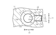
As shown in FIG. 1, the
図2に示すように、挿入凹部13は、例えば、上面視円孔状である。図1に示すように、挿入凹部13は、平坦面状の底面13aと、底面13aの外周縁から円筒状に延びる内周面13bと、を有している。挿入凹部13の底面13aは、水平方向X1に延びている。挿入凹部13の内周面13bは、重力方向Z1(上下方向)に延びている。
As shown in FIG. 2, the
挿入凹部13の内周面13bにおける車両の後方向に位置する部位には、開口部14hを有する収容凹部14が形成されている。よって、収容凹部14は、挿入凹部13の内周面13bの一部分に形成されている。したがって、開口部14hは、挿入凹部13の内周面13bの一部分に形成されている。
A
収容凹部14は、収容凹部14における重力方向Z1の下側に位置する内面が、挿入凹部13の内周面13bから離間するにつれて重力方向Z1の下側に向けて傾斜する傾斜面14aになっている。傾斜面14aは、挿入凹部13の内周面13bに連続している。傾斜面14aは、平坦面状である。
The
収容凹部14における重力方向Z1の上側に位置する内面は、挿入凹部13の内周面13bから離間するにつれて重力方向Z1の下側に向けて傾斜するガイド面14bになっている。ガイド面14bは、挿入凹部13の内周面13bに連続している。ガイド面14bは、平坦面状である。傾斜面14aとガイド面14bとは互いに平行に延びている。
The inner surface of the
収容凹部14の開口部14hとは反対側の内面である底面14cは、重力方向Z1に延びる平坦面状である。底面14cは、傾斜面14aにおける最下端に位置する縁部とガイド面14bにおける最下端に位置する縁部とを接続している。
The
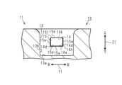
図3に示すように、収容凹部14は、傾斜面14aにおける車両の左右方向Y1に位置する両縁部と、ガイド面14bにおける車両の左右方向Y1に位置する両縁部と、をそれぞれ接続する一対の接続面14dを有している。一対の接続面14dは、重力方向Z1に延びている。一対の接続面14dは互いに平行である。
As shown in FIG. 3, the
開口部14hは、傾斜面14aにおける最上端に位置する縁部、ガイド面14bにおける最上端に位置する縁部、及び一対の接続面14dにおける底面14cとは反対側に位置する縁部によって形成されている。よって、開口部14hは、収容凹部14における挿入凹部13の内周面13b側の縁部である。
The
図1に示すように、カップホルダ10は、出没部材15を有している。出没部材15は、収容凹部14に収容されるとともに収容凹部14に対して出没方向へ移動可能である。よって、出没部材15は、収容凹部14の開口部14hに対して出没方向へ移動可能である。出没部材15は、ブロック状の本体部151と、本体部151に埋設されたウエイト部15gと、を有している。
As shown in FIG. 1, the
出没部材15の本体部151は、傾斜面14aに沿って延びるとともに傾斜面14aに摺接可能な下側摺接面15aと、ガイド面14bに沿って延びるとともにガイド面14bに摺接可能な上側摺接面15bと、を有している。また、出没部材15の本体部151は、収容凹部14の底面14cに沿って延びるとともに下側摺接面15aと上側摺接面15bとを接続する底側面15cを有している。底側面15cには、クッション材16が取り付けられている。クッション材16は、例えば、薄平板状のスポンジ製である。
The
出没部材15の本体部151は、底側面15cとは反対側に位置するとともに下側摺接面15aにおける底側面15cとは反対側の縁部と上側摺接面15bにおける底側面15cとは反対側の縁部とを接続する当接面15dを有している。当接面15dは、平坦面状である。当接面15dと底側面15cとは互いに平行である。クッション材16が収容凹部14の底面14cに接触している状態において、当接面15dは、収容凹部14から僅かに突出している。
The
図3に示すように、出没部材15の本体部151は、下側摺接面15aの両縁部と上側摺接面15bの両縁部とをそれぞれ接続する一対の接続面15eを有している。一対の接続面15eは互いに平行である。一対の接続面15eは、収容凹部14の一対の接続面14dに沿って延びている。
As shown in FIG. 3, the
図1に示すように、ウエイト部15gは、出没部材15の本体部151において、下側摺接面15aと当接面15dとの間の角部15kを通過し、且つ当接面15dに対して直交する方向に延びる仮想平面15fよりも下側摺接面15a側に位置する部分に埋設されている。ウエイト部15gの重量は、本体部151の重量よりも重い。
As shown in FIG. 1, the weight portion 15g passes through the
出没部材15が収容凹部14に収容されている状態において、出没部材15の下側摺接面15aは、収容凹部14の傾斜面14aに接触している。そして、出没部材15の下側摺接面15aが傾斜面14aに接触している状態において、収容凹部14の傾斜面14aは、出没部材15の重力G1の斜面方向の分力F1を発生させ、この分力F1が、出没部材15を収容凹部14(開口部14h)に対する没入方向へ引き込む引き込み力として作用している。よって、収容凹部14の傾斜面14aは、出没部材15を開口部14hに対する没入方向へ引き込む引き込み力を発生させる引き込み力発生部として機能している。
In a state where the
したがって、本実施形態のカップホルダ10は、出没部材15を開口部14hに対する没入方向へ引き込む引き込み力を発生させる引き込み力発生部を有している。そして、本実施形態において、引き込み力発生部は、収容凹部14における重力方向Z1の下側に位置する内面であって、挿入凹部13の内周面13bから離間するにつれて重力方向Z1の下側に向けて傾斜する傾斜面14aである。
Therefore, the
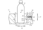
図4に示すように、本実施形態において、車両の前方向は、出没部材15が収容凹部14から挿入凹部13内へ突出する突出方向である。そして、出没部材15は、例えば、車両が急停止する際に車両の前方向への慣性力を受けると、収容凹部14の傾斜面14aにおいて発生する分力F1に抗して収容凹部14から突出する。よって、本実施形態では、出没部材15が車両の前方向への慣性力を受けると、収容凹部14の傾斜面14aにおいて発生する分力F1に抗して収容凹部14から突出するように、傾斜面14aの傾斜角度や出没部材15の重量が予め設定されている。そして、出没部材15は、車両の前方向への慣性力を受けなくなると、収容凹部14の傾斜面14aにおいて発生する分力F1によって収容凹部14内に没入する。
As shown in FIG. 4, in the present embodiment, the front direction of the vehicle is the protruding direction in which the haunting
次に、本実施形態の作用について説明する。
例えば、挿入凹部13に挿入されているペットボトル12の重心G10が、挿入凹部13よりも重力方向Z1の上側に位置している場合を考える。この場合、例えば、車両が急停止する際には、ペットボトル12は、車両の前方向への慣性力を受けて、車両の前方向へ倒れようとする。このとき、出没部材15が、車両の前方向への慣性力を受けて、収容凹部14の傾斜面14aにおいて発生する分力F1に抗して、収容凹部14の傾斜面14a及びガイド面14bに摺接しながら収容凹部14から突出し、出没部材15の当接面15dがペットボトル12に当接する。そして、出没部材15は、ペットボトル12を押圧し、挿入凹部13の内周面13bと協働してペットボトル12を挟み込む。これにより、ペットボトル12が車両の前方向への慣性力を受けても、ペットボトル12の起立状態が保持される。
Next, the operation of this embodiment will be described.
For example, consider a case where the center of gravity G10 of the
また、出没部材15は、車両の前方向への慣性力を受けなくなると、収容凹部14の傾斜面14aにおいて発生する分力F1によって、出没部材15が収容凹部14に対して没入する方向へ移動する。そして、出没部材15は、クッション材16が収容凹部14の底面14cに当接するまで移動する。クッション材16は、収容凹部14の底面14cに当接する際に弾性変形することによって、出没部材15から収容凹部14の底面14cに加わる衝撃力を吸収する。このようにして、出没部材15が収容凹部14内に没入されることにより、ペットボトル12が、出没部材15と挿入凹部13の内周面13bとによって挟み込まれた状態が解除される。
Further, when the haunting
上記実施形態では以下の効果を得ることができる。
(1)出没部材15は、車両の前方向への慣性力を受けると収容凹部14の傾斜面14aにおいて発生する分力F1に抗して収容凹部14(開口部14h)から突出するとともに、車両の前方向への慣性力を受けなくなると、収容凹部14の傾斜面14aにおいて発生する分力F1によって収容凹部14内に没入する。これによれば、出没部材15は、車両の前方向への慣性力を受けると収容凹部14から突出してペットボトル12を押圧し、挿入凹部13の内周面13bと協働してペットボトル12を挟み込む。これにより、ペットボトル12が車両の前方向への慣性力を受けても、ペットボトル12の起立状態が保持される。また、出没部材15は、車両の前方向への慣性力を受けなくなると収容凹部14に対する没入方向に移動するため、ペットボトル12が、出没部材15と挿入凹部13の内周面13bとによって挟み込まれた状態が解除される。よって、出没部材15が車両の前方向への慣性力を受けていない状態であれば、出没部材15は、収容凹部14内に没入しているため、ペットボトル12を挿入凹部13からスムーズに取り出すことができ、さらには、ペットボトル12を挿入凹部13へスムーズに挿入することもできる。以上のことから、ペットボトル12が車両の前方向への慣性力を受けても、ペットボトル12の起立状態を保持することができ、且つペットボトル12における挿入凹部13への挿入やペットボトル12における挿入凹部13からの取り出しを容易に行うことができる。
In the above embodiment, the following effects can be obtained.
(1) The haunting
(2)収容凹部14の傾斜面14aは、出没部材15の下側摺接面15aが傾斜面14aに接触している状態において出没部材15の重力G1の斜面方向の分力F1を発生させ、この分力F1が、出没部材15を収容凹部14に対する没入方向へ引き込む引き込み力として作用する。よって、例えば、出没部材15を収容凹部14に対する没入方向へ引き込む引き込み力を発生させる引き込み部材を、引き込み力発生部として収容凹部14内に別途設ける場合に比べると、カップホルダ10の構成を簡素化することができる。
(2) The
(3)出没部材15は、ウエイト部15gを有している。これによれば、出没部材15がウエイト部15gを有していない場合に比べると、出没部材15の重量が重くなるため、出没部材15の重力G1の分力F1が大きくなり、出没部材15における収容凹部14に対する没入動作をスムーズにすることができる。また、ウエイト部15gの重量を調節することにより、出没部材15の重力G1の分力F1の大きさを調節することができる。したがって、出没部材15を収容凹部14に対する没入方向へ引き込む引き込み力を調節することができる。
(3) The haunting
(4)収容凹部14における重力方向Z1の上側に位置する内面は、挿入凹部13の内周面13bから離間するにつれて重力方向Z1の下側に向けて傾斜するとともに傾斜面14aと平行に延びるガイド面14bになっている。そして、出没部材15は、ガイド面14bに沿って延びるとともにガイド面14bに摺接可能な上側摺接面15bを有している。これによれば、出没部材15が、収容凹部14の傾斜面14a及びガイド面14bに摺接しながら収容凹部14内を移動するため、出没部材15が収容凹部14内を移動する際に傾いてしまうことが抑制され、出没部材15における収容凹部14に対する移動をスムーズにすることができる。
(4) The inner surface of the
(5)出没部材15の底側面15cにはクッション材16が取り付けられている。これによれば、クッション材16が、収容凹部14の底面14cに当接する際に弾性変形することによって、出没部材15から収容凹部14の底面14cに加わる衝撃力を吸収することができる。
(5) A
なお、上記実施形態は、以下のように変更して実施することができる。上記実施形態及び以下の変更例は、技術的に矛盾しない範囲で互いに組み合わせて実施することができる。 The above embodiment can be modified and implemented as follows. The above embodiment and the following modified examples can be implemented in combination with each other within a technically consistent range.
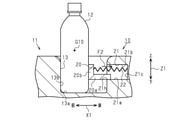
○ 図5及び図6に示すように、例えば、出没部材20を収容凹部21に対する没入方向へ引き込む引き込み力を発生させる引張ばね22を、引き込み力発生部として収容凹部21内に別途設けてもよい。収容凹部21における重力方向Z1の下側に位置する下内面21a、及び収容凹部21における重力方向Z1の上側に位置する上内面21bは、水平方向X1に延びている。出没部材20は、収容凹部21の下内面21aに沿って延びる支持壁20aと、支持壁20aに対して直交する方向に延びる当接壁20bと、から構成されている。引張ばね22は、収容凹部21の開口部21hとは反対側の内面である底面21cと出没部材20の当接壁20bとの間に介在されている。引張ばね22の一端は収容凹部21の底面21cに支持されるとともに、引張ばね22の他端は出没部材20の当接壁20bに支持されている。出没部材20は、引張ばね22の引張力F2によって収容凹部21に対する没入方向へ引き込まれている。よって、引張ばね22は、出没部材20を収容凹部21に対する没入方向へ引き込む引き込み力を発生させている。
○ As shown in FIGS. 5 and 6, for example, a
出没部材20は、車両の前方向への慣性力を受けると、引張ばね22の引張力F2に抗して収容凹部21から突出し、出没部材20の当接壁20bがペットボトル12に当接する。そして、出没部材20は、ペットボトル12を押圧し、挿入凹部13の内周面13bと協働してペットボトル12を挟み込む。これにより、ペットボトル12が車両の前方向への慣性力を受けても、ペットボトル12の起立状態が保持される。また、出没部材20は、車両の前方向への慣性力を受けなくなると、引張ばね22の引張力F2によって、出没部材20が収容凹部21に対して没入する方向へ移動する。そして、出没部材20が収容凹部21内に没入されることにより、ペットボトル12が、出没部材20と挿入凹部13の内周面13bとによって挟み込まれた状態が解除される。
When the
○ 実施形態において、例えば、挿入凹部13の内周面13bにおける車両の前方向に位置する部位に収容凹部14が形成されており、この収容凹部14に出没部材15が収容されていてもよい。これによれば、出没部材15は、例えば、車両が急発進する際に車両の後方向への慣性力を受けると、収容凹部14の傾斜面14aにおいて発生する分力F1に抗して収容凹部14から突出し、挿入凹部13の内周面13bと協働してペットボトル12を挟み込む。これにより、ペットボトル12が車両の後方向への慣性力を受けても、ペットボトル12の起立状態が保持される。
○ In the embodiment, for example, the
○ 実施形態において、例えば、挿入凹部13の内周面13bにおける車両の右方向に位置する部位に収容凹部14が形成されており、この収容凹部14に出没部材15が収容されていてもよい。これによれば、出没部材15は、例えば、車両が右カーブを走行している際に車両の左方向への慣性力(遠心力)を受けると、収容凹部14の傾斜面14aにおいて発生する分力F1に抗して収容凹部14から突出し、挿入凹部13の内周面13bと協働してペットボトル12を挟み込む。これにより、ペットボトル12が車両の左方向への慣性力を受けても、ペットボトル12の起立状態が保持される。
○ In the embodiment, for example, an
○ 実施形態において、例えば、挿入凹部13の内周面13bにおける車両の左方向に位置する部位に収容凹部14が形成されており、この収容凹部14に出没部材15が収容されていてもよい。これによれば、出没部材15は、例えば、車両が左カーブを走行している際に車両の右方向への慣性力(遠心力)を受けると、収容凹部14の傾斜面14aにおいて発生する分力F1に抗して収容凹部14から突出し、挿入凹部13の内周面13bと協働してペットボトル12を挟み込む。これにより、ペットボトル12が車両の右方向への慣性力を受けても、ペットボトル12の起立状態が保持される。
○ In the embodiment, for example, an
〇 実施形態において、出没部材15の本体部151にウエイト部15gが埋設されていなくてもよく、出没部材15がウエイト部15gを有していなくてもよい。
○ 実施形態において、出没部材15は、ウエイト部15gを有していなくてもよく、例えば、出没部材15が、当接面15dを有する板状の当接壁と、下側摺接面15aを有する板状の傾斜壁と、から構成されていてもよい。
〇 In the embodiment, the weight portion 15g may not be embedded in the
○ In the embodiment, the haunting
○ 実施形態において、出没部材15の当接面15dが、挿入凹部13の内周面13bに沿って延びる円弧状であってもよい。
○ 実施形態において、出没部材15の当接面15dは、クッション材16が収容凹部14の底面14cに接触している状態において、収容凹部14から突出していなくてもよい。
○ In the embodiment, the
○ In the embodiment, the
○ 実施形態において、出没部材15の底側面15cにクッション材16が取り付けられていなくてもよい。
○ 実施形態において、出没部材15の底側面15cにクッション材16が取り付けられているのではなく、収容凹部14の底面14cにクッション材16が取り付けられていてもよい。
○ In the embodiment, the
○ In the embodiment, the
○ 実施形態において、収容凹部14における重力方向Z1の上側に位置する内面が、例えば、水平方向X1に延びていてもよい。
〇 実施形態において、出没部材15が一定以上の車両の慣性力を受けると、収容凹部14の傾斜面14aにおいて発生する分力F1に抗して収容凹部14から突出するようにしてもよい。ここで、「一定以上の車両の慣性力」とは、挿入凹部13に挿入されているペットボトル12が車両の慣性力によって倒れてしまうと想定される慣性力のことである。この場合、車両の慣性力が一定以上になるまでは、出没部材15が収容凹部14から突出しないように、収容凹部14の傾斜面14aにおいて発生する分力F1が調整されている。この分力F1の調整は、例えば、ウエイト部15gの重量を調節したり、収容凹部14の傾斜面14aの傾斜角度を調節したりすることにより行われる。
O In the embodiment, the inner surface of the
〇 In the embodiment, when the haunting
〇 実施形態において、挿入凹部13の内周面13bの一部分に、例えば、コンソールボックス11の一部分を貫通する貫通孔を形成することにより、挿入凹部13の内周面13bの一部分に開口部を形成してもよい。
〇 In the embodiment, an opening is formed in a part of the inner
○ 実施形態において、カップホルダ10が設けられる場所は、車両の車室内の運転席と助手席との間に配設されるコンソールボックス11に限らない。
○ 実施形態において、カップホルダ10に保持される保持対象物としては、ペットボトル12に限らず、例えば、缶や紙コップ等の飲料容器であってもよい。また、保持対象物としては、飲料容器に限らず、例えば、携帯電話等を保持対象物としてもよい。
○ In the embodiment, the place where the
○ In the embodiment, the object to be held in the
○ 実施形態において、車両用保持装置としては、ペットボトル12等の飲料容器を挿入凹部13内で起立状態に保持することを目的としたカップホルダ10に限らず、例えば、携帯電話を挿入凹部13内で起立状態に保持することを目的とした車両用保持装置であってもよい。
○ In the embodiment, the vehicle holding device is not limited to the
10…車両用保持装置であるカップホルダ、12…保持対象物であるペットボトル、13…挿入凹部、13b…内周面、14,21…収容凹部、14a…引き込み力発生部である傾斜面、14b…ガイド面、14h,21h…開口部、15,20…出没部材、15a…下側摺接面、15b…上側摺接面、15g…ウエイト部、22…引き込み力発生部としての引張ばね。 10 ... a cup holder that is a holding device for a vehicle, 12 ... a PET bottle that is a holding object, 13 ... an insertion recess, 13b ... an inner peripheral surface, 14, 21 ... a storage recess, 14a ... an inclined surface that is a pulling force generating portion, 14b ... Guide surface, 14h, 21h ... Opening, 15, 20 ... Infestation member, 15a ... Lower sliding contact surface, 15b ... Upper sliding contact surface, 15g ... Weight part, 22 ... Tension spring as pulling force generating part.
Claims (4)
前記挿入凹部の内周面の一部分に形成される開口部と、
前記開口部に対して出没方向へ移動可能な出没部材と、
前記出没部材を前記開口部に対する没入方向へ引き込む引き込み力を発生させる引き込み力発生部と、を有し、
前記出没部材は、前記開口部から前記挿入凹部内へ突出する突出方向へ作用する車両の慣性力を受けると前記引き込み力に抗して前記開口部から突出するとともに、前記慣性力を受けなくなると前記引き込み力によって前記没入方向に移動することを特徴とする車両用保持装置。 A vehicle holding device having an insertion recess into which a holding object is inserted from above and holding the holding object in an upright state in the insertion recess.
An opening formed in a part of the inner peripheral surface of the insertion recess and
A haunting member that can move in the haunting direction with respect to the opening,
It has a pull-in force generating portion that generates a pull-in force that pulls the haunting member in the immersion direction with respect to the opening.
When the infested member receives the inertial force of the vehicle acting in the projecting direction protruding from the opening into the insertion recess, it protrudes from the opening against the pulling force and does not receive the inertial force. A vehicle holding device characterized in that it moves in the immersion direction by the pulling force.
前記引き込み力発生部は、前記収容凹部における重力方向の下側に位置する内面であって、前記挿入凹部の内周面から離間するにつれて前記重力方向の下側に向けて傾斜する傾斜面であり、
前記出没部材は、前記傾斜面に沿って延びるとともに前記傾斜面に摺接可能な下側摺接面を有していることを特徴とする請求項1に記載の車両用保持装置。 A housing recess having the opening is formed in a part of the inner peripheral surface of the insertion recess.
The pulling force generating portion is an inner surface of the accommodating recess located on the lower side in the gravity direction, and is an inclined surface that inclines toward the lower side in the gravity direction as the insertion recess is separated from the inner peripheral surface of the insertion recess. ,
The vehicle holding device according to claim 1, wherein the haunting member extends along the inclined surface and has a lower sliding contact surface that can be slidably contacted with the inclined surface.
前記出没部材は、前記ガイド面に沿って延びるとともに前記ガイド面に摺接可能な上側摺接面を有していることを特徴とする請求項2又は請求項3に記載の車両用保持装置。 The inner surface of the accommodating recess located on the upper side in the gravity direction is a guide surface that inclines toward the lower side in the gravity direction and extends in parallel with the inclined surface as it is separated from the inner peripheral surface of the insertion recess.
The vehicle holding device according to claim 2 or 3, wherein the haunting member extends along the guide surface and has an upper sliding contact surface that can be slidably contacted with the guide surface.
Priority Applications (1)
| Application Number | Priority Date | Filing Date | Title |
|---|---|---|---|
| JP2018186726A JP6996466B2 (en) | 2018-10-01 | 2018-10-01 | Vehicle holding device |
Applications Claiming Priority (1)
| Application Number | Priority Date | Filing Date | Title |
|---|---|---|---|
| JP2018186726A JP6996466B2 (en) | 2018-10-01 | 2018-10-01 | Vehicle holding device |
Publications (2)
| Publication Number | Publication Date |
|---|---|
| JP2020055401A JP2020055401A (en) | 2020-04-09 |
| JP6996466B2 true JP6996466B2 (en) | 2022-01-17 |
Family
ID=70106146
Family Applications (1)
| Application Number | Title | Priority Date | Filing Date |
|---|---|---|---|
| JP2018186726A Expired - Fee Related JP6996466B2 (en) | 2018-10-01 | 2018-10-01 | Vehicle holding device |
Country Status (1)
| Country | Link |
|---|---|
| JP (1) | JP6996466B2 (en) |
Citations (3)
| Publication number | Priority date | Publication date | Assignee | Title |
|---|---|---|---|---|
| JP2005329824A (en) | 2004-05-20 | 2005-12-02 | Kojima Press Co Ltd | Cup holder for vehicle |
| JP2010076710A (en) | 2008-09-29 | 2010-04-08 | Nissan Motor Co Ltd | On-vehicle storage case |
| JP2017077761A (en) | 2015-10-19 | 2017-04-27 | トヨタ自動車株式会社 | Vehicle tray |
-
2018
- 2018-10-01 JP JP2018186726A patent/JP6996466B2/en not_active Expired - Fee Related
Patent Citations (3)
| Publication number | Priority date | Publication date | Assignee | Title |
|---|---|---|---|---|
| JP2005329824A (en) | 2004-05-20 | 2005-12-02 | Kojima Press Co Ltd | Cup holder for vehicle |
| JP2010076710A (en) | 2008-09-29 | 2010-04-08 | Nissan Motor Co Ltd | On-vehicle storage case |
| JP2017077761A (en) | 2015-10-19 | 2017-04-27 | トヨタ自動車株式会社 | Vehicle tray |
Also Published As
| Publication number | Publication date |
|---|---|
| JP2020055401A (en) | 2020-04-09 |
Similar Documents
| Publication | Publication Date | Title |
|---|---|---|
| US7168669B2 (en) | Beverage container holder for vehicle | |
| US9975493B2 (en) | Vehicular console device | |
| US20080100068A1 (en) | Locking device of tray for vehicle | |
| JP2021167192A (en) | Beverage container holding device | |
| JP6391548B2 (en) | Vehicle storage device | |
| JP6996466B2 (en) | Vehicle holding device | |
| JP6841923B2 (en) | Container storage structure | |
| KR101969661B1 (en) | Holding device for a beverage container | |
| JP6241221B2 (en) | Under tray arrangement structure of vehicle seat | |
| JP6106048B2 (en) | Cup holder | |
| JP5140033B2 (en) | Storage structure | |
| CN104442588B (en) | Vehicle tray structure | |
| KR100944880B1 (en) | Console tray for automobile | |
| JP5236207B2 (en) | Tonneau cover device | |
| WO2023038021A1 (en) | Cup holder structure for vehicle | |
| JP4736638B2 (en) | Cup holder device | |
| JP6555146B2 (en) | Holder device and vehicle seat | |
| JP5825198B2 (en) | Storage device | |
| JP2022012672A (en) | Storage structure for vehicle and storage component | |
| JP6570394B2 (en) | In-vehicle drink holder structure | |
| KR100654984B1 (en) | Damper Structure of Vehicle Tray | |
| CA3066438A1 (en) | Gift card presentation device | |
| JP2019031252A (en) | Door interior structure for vehicle | |
| KR100657701B1 (en) | Expandable Vehicle Console Box | |
| JP2005212516A (en) | Storing device |
Legal Events
| Date | Code | Title | Description |
|---|---|---|---|
| A621 | Written request for application examination |
Free format text: JAPANESE INTERMEDIATE CODE: A621 Effective date: 20210120 |
|
| A977 | Report on retrieval |
Free format text: JAPANESE INTERMEDIATE CODE: A971007 Effective date: 20211022 |
|
| TRDD | Decision of grant or rejection written | ||
| A01 | Written decision to grant a patent or to grant a registration (utility model) |
Free format text: JAPANESE INTERMEDIATE CODE: A01 Effective date: 20211116 |
|
| A61 | First payment of annual fees (during grant procedure) |
Free format text: JAPANESE INTERMEDIATE CODE: A61 Effective date: 20211129 |
|
| R151 | Written notification of patent or utility model registration |
Ref document number: 6996466 Country of ref document: JP Free format text: JAPANESE INTERMEDIATE CODE: R151 |
|
| LAPS | Cancellation because of no payment of annual fees |