JP6996414B2 - Manufacturing method of sulfide solid-state battery - Google Patents
Manufacturing method of sulfide solid-state battery Download PDFInfo
- Publication number
- JP6996414B2 JP6996414B2 JP2018087219A JP2018087219A JP6996414B2 JP 6996414 B2 JP6996414 B2 JP 6996414B2 JP 2018087219 A JP2018087219 A JP 2018087219A JP 2018087219 A JP2018087219 A JP 2018087219A JP 6996414 B2 JP6996414 B2 JP 6996414B2
- Authority
- JP
- Japan
- Prior art keywords
- negative electrode
- lithium
- sulfide solid
- doped
- active material
- Prior art date
- Legal status (The legal status is an assumption and is not a legal conclusion. Google has not performed a legal analysis and makes no representation as to the accuracy of the status listed.)
- Active
Links
Images
Classifications
-
- H—ELECTRICITY
- H01—ELECTRIC ELEMENTS
- H01M—PROCESSES OR MEANS, e.g. BATTERIES, FOR THE DIRECT CONVERSION OF CHEMICAL ENERGY INTO ELECTRICAL ENERGY
- H01M4/00—Electrodes
- H01M4/02—Electrodes composed of, or comprising, active material
- H01M4/36—Selection of substances as active materials, active masses, active liquids
- H01M4/58—Selection of substances as active materials, active masses, active liquids of inorganic compounds other than oxides or hydroxides, e.g. sulfides, selenides, tellurides, halogenides or LiCoFy; of polyanionic structures, e.g. phosphates, silicates or borates
- H01M4/583—Carbonaceous material, e.g. graphite-intercalation compounds or CFx
- H01M4/587—Carbonaceous material, e.g. graphite-intercalation compounds or CFx for inserting or intercalating light metals
-
- H—ELECTRICITY
- H01—ELECTRIC ELEMENTS
- H01M—PROCESSES OR MEANS, e.g. BATTERIES, FOR THE DIRECT CONVERSION OF CHEMICAL ENERGY INTO ELECTRICAL ENERGY
- H01M4/00—Electrodes
- H01M4/02—Electrodes composed of, or comprising, active material
- H01M4/04—Processes of manufacture in general
- H01M4/0402—Methods of deposition of the material
- H01M4/0404—Methods of deposition of the material by coating on electrode collectors
-
- H—ELECTRICITY
- H01—ELECTRIC ELEMENTS
- H01M—PROCESSES OR MEANS, e.g. BATTERIES, FOR THE DIRECT CONVERSION OF CHEMICAL ENERGY INTO ELECTRICAL ENERGY
- H01M4/00—Electrodes
- H01M4/02—Electrodes composed of, or comprising, active material
- H01M4/13—Electrodes for accumulators with non-aqueous electrolyte, e.g. for lithium-accumulators; Processes of manufacture thereof
- H01M4/139—Processes of manufacture
-
- H—ELECTRICITY
- H01—ELECTRIC ELEMENTS
- H01M—PROCESSES OR MEANS, e.g. BATTERIES, FOR THE DIRECT CONVERSION OF CHEMICAL ENERGY INTO ELECTRICAL ENERGY
- H01M4/00—Electrodes
- H01M4/02—Electrodes composed of, or comprising, active material
- H01M4/13—Electrodes for accumulators with non-aqueous electrolyte, e.g. for lithium-accumulators; Processes of manufacture thereof
- H01M4/133—Electrodes based on carbonaceous material, e.g. graphite-intercalation compounds or CFx
-
- H—ELECTRICITY
- H01—ELECTRIC ELEMENTS
- H01M—PROCESSES OR MEANS, e.g. BATTERIES, FOR THE DIRECT CONVERSION OF CHEMICAL ENERGY INTO ELECTRICAL ENERGY
- H01M10/00—Secondary cells; Manufacture thereof
- H01M10/05—Accumulators with non-aqueous electrolyte
- H01M10/052—Li-accumulators
-
- H—ELECTRICITY
- H01—ELECTRIC ELEMENTS
- H01M—PROCESSES OR MEANS, e.g. BATTERIES, FOR THE DIRECT CONVERSION OF CHEMICAL ENERGY INTO ELECTRICAL ENERGY
- H01M10/00—Secondary cells; Manufacture thereof
- H01M10/05—Accumulators with non-aqueous electrolyte
- H01M10/052—Li-accumulators
- H01M10/0525—Rocking-chair batteries, i.e. batteries with lithium insertion or intercalation in both electrodes; Lithium-ion batteries
-
- H—ELECTRICITY
- H01—ELECTRIC ELEMENTS
- H01M—PROCESSES OR MEANS, e.g. BATTERIES, FOR THE DIRECT CONVERSION OF CHEMICAL ENERGY INTO ELECTRICAL ENERGY
- H01M10/00—Secondary cells; Manufacture thereof
- H01M10/05—Accumulators with non-aqueous electrolyte
- H01M10/056—Accumulators with non-aqueous electrolyte characterised by the materials used as electrolytes, e.g. mixed inorganic/organic electrolytes
- H01M10/0561—Accumulators with non-aqueous electrolyte characterised by the materials used as electrolytes, e.g. mixed inorganic/organic electrolytes the electrolyte being constituted of inorganic materials only
- H01M10/0562—Solid materials
-
- H—ELECTRICITY
- H01—ELECTRIC ELEMENTS
- H01M—PROCESSES OR MEANS, e.g. BATTERIES, FOR THE DIRECT CONVERSION OF CHEMICAL ENERGY INTO ELECTRICAL ENERGY
- H01M10/00—Secondary cells; Manufacture thereof
- H01M10/05—Accumulators with non-aqueous electrolyte
- H01M10/058—Construction or manufacture
-
- H—ELECTRICITY
- H01—ELECTRIC ELEMENTS
- H01M—PROCESSES OR MEANS, e.g. BATTERIES, FOR THE DIRECT CONVERSION OF CHEMICAL ENERGY INTO ELECTRICAL ENERGY
- H01M10/00—Secondary cells; Manufacture thereof
- H01M10/05—Accumulators with non-aqueous electrolyte
- H01M10/058—Construction or manufacture
- H01M10/0585—Construction or manufacture of accumulators having only flat construction elements, i.e. flat positive electrodes, flat negative electrodes and flat separators
-
- H—ELECTRICITY
- H01—ELECTRIC ELEMENTS
- H01M—PROCESSES OR MEANS, e.g. BATTERIES, FOR THE DIRECT CONVERSION OF CHEMICAL ENERGY INTO ELECTRICAL ENERGY
- H01M4/00—Electrodes
- H01M4/02—Electrodes composed of, or comprising, active material
-
- H—ELECTRICITY
- H01—ELECTRIC ELEMENTS
- H01M—PROCESSES OR MEANS, e.g. BATTERIES, FOR THE DIRECT CONVERSION OF CHEMICAL ENERGY INTO ELECTRICAL ENERGY
- H01M4/00—Electrodes
- H01M4/02—Electrodes composed of, or comprising, active material
- H01M4/13—Electrodes for accumulators with non-aqueous electrolyte, e.g. for lithium-accumulators; Processes of manufacture thereof
- H01M4/134—Electrodes based on metals, Si or alloys
-
- H—ELECTRICITY
- H01—ELECTRIC ELEMENTS
- H01M—PROCESSES OR MEANS, e.g. BATTERIES, FOR THE DIRECT CONVERSION OF CHEMICAL ENERGY INTO ELECTRICAL ENERGY
- H01M4/00—Electrodes
- H01M4/02—Electrodes composed of, or comprising, active material
- H01M4/13—Electrodes for accumulators with non-aqueous electrolyte, e.g. for lithium-accumulators; Processes of manufacture thereof
- H01M4/139—Processes of manufacture
- H01M4/1391—Processes of manufacture of electrodes based on mixed oxides or hydroxides, or on mixtures of oxides or hydroxides, e.g. LiCoOx
-
- H—ELECTRICITY
- H01—ELECTRIC ELEMENTS
- H01M—PROCESSES OR MEANS, e.g. BATTERIES, FOR THE DIRECT CONVERSION OF CHEMICAL ENERGY INTO ELECTRICAL ENERGY
- H01M4/00—Electrodes
- H01M4/02—Electrodes composed of, or comprising, active material
- H01M4/13—Electrodes for accumulators with non-aqueous electrolyte, e.g. for lithium-accumulators; Processes of manufacture thereof
- H01M4/139—Processes of manufacture
- H01M4/1393—Processes of manufacture of electrodes based on carbonaceous material, e.g. graphite-intercalation compounds or CFx
-
- H—ELECTRICITY
- H01—ELECTRIC ELEMENTS
- H01M—PROCESSES OR MEANS, e.g. BATTERIES, FOR THE DIRECT CONVERSION OF CHEMICAL ENERGY INTO ELECTRICAL ENERGY
- H01M4/00—Electrodes
- H01M4/02—Electrodes composed of, or comprising, active material
- H01M4/13—Electrodes for accumulators with non-aqueous electrolyte, e.g. for lithium-accumulators; Processes of manufacture thereof
- H01M4/139—Processes of manufacture
- H01M4/1395—Processes of manufacture of electrodes based on metals, Si or alloys
-
- H—ELECTRICITY
- H01—ELECTRIC ELEMENTS
- H01M—PROCESSES OR MEANS, e.g. BATTERIES, FOR THE DIRECT CONVERSION OF CHEMICAL ENERGY INTO ELECTRICAL ENERGY
- H01M4/00—Electrodes
- H01M4/02—Electrodes composed of, or comprising, active material
- H01M4/13—Electrodes for accumulators with non-aqueous electrolyte, e.g. for lithium-accumulators; Processes of manufacture thereof
- H01M4/139—Processes of manufacture
- H01M4/1397—Processes of manufacture of electrodes based on inorganic compounds other than oxides or hydroxides, e.g. sulfides, selenides, tellurides, halogenides or LiCoFy
-
- H—ELECTRICITY
- H01—ELECTRIC ELEMENTS
- H01M—PROCESSES OR MEANS, e.g. BATTERIES, FOR THE DIRECT CONVERSION OF CHEMICAL ENERGY INTO ELECTRICAL ENERGY
- H01M4/00—Electrodes
- H01M4/02—Electrodes composed of, or comprising, active material
- H01M4/36—Selection of substances as active materials, active masses, active liquids
- H01M4/362—Composites
- H01M4/364—Composites as mixtures
-
- H—ELECTRICITY
- H01—ELECTRIC ELEMENTS
- H01M—PROCESSES OR MEANS, e.g. BATTERIES, FOR THE DIRECT CONVERSION OF CHEMICAL ENERGY INTO ELECTRICAL ENERGY
- H01M4/00—Electrodes
- H01M4/02—Electrodes composed of, or comprising, active material
- H01M4/36—Selection of substances as active materials, active masses, active liquids
- H01M4/38—Selection of substances as active materials, active masses, active liquids of elements or alloys
- H01M4/386—Silicon or alloys based on silicon
-
- H—ELECTRICITY
- H01—ELECTRIC ELEMENTS
- H01M—PROCESSES OR MEANS, e.g. BATTERIES, FOR THE DIRECT CONVERSION OF CHEMICAL ENERGY INTO ELECTRICAL ENERGY
- H01M4/00—Electrodes
- H01M4/02—Electrodes composed of, or comprising, active material
- H01M4/36—Selection of substances as active materials, active masses, active liquids
- H01M4/48—Selection of substances as active materials, active masses, active liquids of inorganic oxides or hydroxides
- H01M4/485—Selection of substances as active materials, active masses, active liquids of inorganic oxides or hydroxides of mixed oxides or hydroxides for inserting or intercalating light metals, e.g. LiTi2O4 or LiTi2OxFy
-
- H—ELECTRICITY
- H01—ELECTRIC ELEMENTS
- H01M—PROCESSES OR MEANS, e.g. BATTERIES, FOR THE DIRECT CONVERSION OF CHEMICAL ENERGY INTO ELECTRICAL ENERGY
- H01M4/00—Electrodes
- H01M4/02—Electrodes composed of, or comprising, active material
- H01M4/36—Selection of substances as active materials, active masses, active liquids
- H01M4/58—Selection of substances as active materials, active masses, active liquids of inorganic compounds other than oxides or hydroxides, e.g. sulfides, selenides, tellurides, halogenides or LiCoFy; of polyanionic structures, e.g. phosphates, silicates or borates
- H01M4/583—Carbonaceous material, e.g. graphite-intercalation compounds or CFx
-
- H—ELECTRICITY
- H01—ELECTRIC ELEMENTS
- H01M—PROCESSES OR MEANS, e.g. BATTERIES, FOR THE DIRECT CONVERSION OF CHEMICAL ENERGY INTO ELECTRICAL ENERGY
- H01M4/00—Electrodes
- H01M4/02—Electrodes composed of, or comprising, active material
- H01M2004/026—Electrodes composed of, or comprising, active material characterised by the polarity
- H01M2004/027—Negative electrodes
-
- H—ELECTRICITY
- H01—ELECTRIC ELEMENTS
- H01M—PROCESSES OR MEANS, e.g. BATTERIES, FOR THE DIRECT CONVERSION OF CHEMICAL ENERGY INTO ELECTRICAL ENERGY
- H01M2300/00—Electrolytes
- H01M2300/0017—Non-aqueous electrolytes
- H01M2300/0065—Solid electrolytes
- H01M2300/0068—Solid electrolytes inorganic
-
- Y—GENERAL TAGGING OF NEW TECHNOLOGICAL DEVELOPMENTS; GENERAL TAGGING OF CROSS-SECTIONAL TECHNOLOGIES SPANNING OVER SEVERAL SECTIONS OF THE IPC; TECHNICAL SUBJECTS COVERED BY FORMER USPC CROSS-REFERENCE ART COLLECTIONS [XRACs] AND DIGESTS
- Y02—TECHNOLOGIES OR APPLICATIONS FOR MITIGATION OR ADAPTATION AGAINST CLIMATE CHANGE
- Y02E—REDUCTION OF GREENHOUSE GAS [GHG] EMISSIONS, RELATED TO ENERGY GENERATION, TRANSMISSION OR DISTRIBUTION
- Y02E60/00—Enabling technologies; Technologies with a potential or indirect contribution to GHG emissions mitigation
- Y02E60/10—Energy storage using batteries
-
- Y—GENERAL TAGGING OF NEW TECHNOLOGICAL DEVELOPMENTS; GENERAL TAGGING OF CROSS-SECTIONAL TECHNOLOGIES SPANNING OVER SEVERAL SECTIONS OF THE IPC; TECHNICAL SUBJECTS COVERED BY FORMER USPC CROSS-REFERENCE ART COLLECTIONS [XRACs] AND DIGESTS
- Y02—TECHNOLOGIES OR APPLICATIONS FOR MITIGATION OR ADAPTATION AGAINST CLIMATE CHANGE
- Y02P—CLIMATE CHANGE MITIGATION TECHNOLOGIES IN THE PRODUCTION OR PROCESSING OF GOODS
- Y02P70/00—Climate change mitigation technologies in the production process for final industrial or consumer products
- Y02P70/50—Manufacturing or production processes characterised by the final manufactured product
Landscapes
- Chemical & Material Sciences (AREA)
- Chemical Kinetics & Catalysis (AREA)
- General Chemical & Material Sciences (AREA)
- Electrochemistry (AREA)
- Engineering & Computer Science (AREA)
- Manufacturing & Machinery (AREA)
- Materials Engineering (AREA)
- Inorganic Chemistry (AREA)
- Physics & Mathematics (AREA)
- Condensed Matter Physics & Semiconductors (AREA)
- General Physics & Mathematics (AREA)
- Composite Materials (AREA)
- Battery Electrode And Active Subsutance (AREA)
- Secondary Cells (AREA)
- Cell Electrode Carriers And Collectors (AREA)
Description
本願は硫化物固体電池の製造方法を開示する。 The present application discloses a method for manufacturing a sulfide solid state battery.
特許文献1~3には、正極と、負極と、正極及び負極の間に設けられた固体電解質層とを備える硫化物固体電池が開示されている。特許文献1に開示された技術おいては、硫化物固体電解質とシリコン系活物質と炭素系活物質とを含む負極合材を、銅からなる負極集電体の表面に積層して負極を得ている。特許文献2に開示された技術においては、硫化物固体電池の初回充電時の電池の使用電圧に達するまでの間に正極から負極へとリチウムを供給して負極活物質中にリチウムをドープしている。特許文献3に開示された技術においては、硫化物固体電解質を含む負極合材を負極集電体の表面に積層する前に負極集電体の表面に耐硫化性層を設けている。
硫化物固体電池の電極のリチウム標準電位は充放電前の活物質のOCVと同等となる。例えば負極集電体の表面にシリコン系活物質を含む負極合材を積層して負極を構成した場合、負極は約2.8Vのリチウム標準電位を有する。 The lithium standard potential of the electrode of the sulfide solid-state battery is equivalent to the OCV of the active material before charging and discharging. For example, when a negative electrode mixture containing a silicon-based active material is laminated on the surface of a negative electrode current collector to form a negative electrode, the negative electrode has a lithium standard potential of about 2.8 V.
一方、本発明者の知見によれば、銅を含む負極集電体の表面に硫化物固体電解質を含む負極合材を積層して負極を構成した場合、2.8Vよりも卑な電位において、硫化物固体電解質と銅とが反応し、導電性を有するCuS等が生成する。 On the other hand, according to the findings of the present inventor, when a negative electrode mixture containing a sulfide solid electrolyte is laminated on the surface of a negative electrode current collector containing copper to form a negative electrode, the negative electrode is formed at a potential lower than 2.8 V. The sulfide solid electrolyte reacts with copper to produce conductive CuS and the like.
すなわち、銅を含む負極集電体の表面にシリコン系活物質及び硫化物固体電解質を含む負極合材を積層して負極を構成した場合、シリコン系活物質のOCVにて硫化物固体電解質と銅とが反応し、硫化物固体電解質を介して負極集電体から正極側に銅が拡散する。このような負極を用いて硫化物固体電池を製造した場合、正極と負極との微短絡を原因とする自己放電等が生じる虞がある。 That is, when a negative electrode mixture containing a silicon-based active material and a sulfide solid electrolyte is laminated on the surface of a negative electrode current collector containing copper to form a negative electrode, the sulfide solid electrolyte and copper are formed by OCV of the silicon-based active material. Reacts with and diffuses copper from the negative electrode current collector to the positive electrode side via the sulfide solid electrolyte. When a sulfide solid-state battery is manufactured using such a negative electrode, self-discharge or the like may occur due to a slight short circuit between the positive electrode and the negative electrode.
本願は上記課題を解決するための手段の一つとして、黒鉛とチタン酸リチウムとから選ばれる少なくとも1種の材料にリチウムをドープしてプレドープ材を得る、第1工程、硫化物固体電解質とシリコン系活物質と前記プレドープ材とを混合して負極合材を得る、第2工程、及び、銅を含む負極集電体の表面に前記負極合材を積層して負極を得る、第3工程、を備える、硫化物固体電池の製造方法を開示する。 The present application provides a pre-doped material by doping at least one material selected from graphite and lithium titanate with lithium as one of the means for solving the above problems, the first step, a sulfide solid electrolyte and silicon. The second step of mixing the active material and the pre-doped material to obtain a negative electrode mixture, and the third step of laminating the negative electrode mixture on the surface of a negative electrode current collector containing copper to obtain a negative electrode. Disclose a method for manufacturing a sulfide solid-state battery.
本開示の製造方法においては、前記負極合材に含まれる前記プレドープ材にドープされたリチウムの総量の容量換算値(X)と、前記負極合材に含まれる前記シリコン系活物質の総容量(Y)との比(X/Y)を、0.0005以上とすることが好ましい。 In the manufacturing method of the present disclosure, the capacity conversion value (X) of the total amount of lithium doped in the pre-doped material contained in the negative electrode mixture and the total capacity of the silicon-based active material contained in the negative electrode mixture (X). The ratio (X / Y) to Y) is preferably 0.0005 or more.
本開示の製造方法においては、前記第1工程において、リチウムイオン電池における電気化学反応を利用して前記材料にリチウムをドープすることが好ましい。 In the production method of the present disclosure, it is preferable to dope lithium into the material in the first step by utilizing an electrochemical reaction in a lithium ion battery.
本開示の製造方法においては、シリコン系活物質とともに所定のプレドープ材を混合して負極合材を作製する。この場合、負極合材を作製した直後にプレドープ材からシリコン系活物質へとリチウムが拡散し、負極とした場合の電位が低下する。すなわち、硫化物固体電解質と銅との反応を抑制でき、硫化物固体電解質を介して負極集電体から正極側に銅が拡散することを抑制でき、正極と負極との微短絡を原因とする自己放電等を抑制できる。また、プレドープ材は導電性及び/又はイオン伝導性を有したまま負極中に存在することとなることから、電池特性の弊害となり難い。 In the manufacturing method of the present disclosure, a predetermined pre-doped material is mixed with a silicon-based active material to prepare a negative electrode mixture. In this case, immediately after the negative electrode mixture is produced, lithium diffuses from the pre-doped material to the silicon-based active material, and the potential when the negative electrode is used is lowered. That is, the reaction between the sulfide solid electrolyte and copper can be suppressed, and the diffusion of copper from the negative electrode current collector to the positive electrode side via the sulfide solid electrolyte can be suppressed, causing a slight short circuit between the positive electrode and the negative electrode. Self-discharge and the like can be suppressed. Further, since the pre-doped material exists in the negative electrode while having conductivity and / or ionic conductivity, it is unlikely to adversely affect the battery characteristics.
1.硫化物固体電池の製造方法
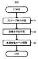
図1~3を参照しつつ硫化物固体電池100の製造方法S10の流れを説明する。硫化物固体電池100の製造方法S10は、黒鉛とチタン酸リチウムとから選ばれる少なくとも1種の材料1にリチウムをドープしてプレドープ材2を得る、第1工程S1、硫化物固体電解質3とシリコン系活物質4とプレドープ材2とを混合して負極合材5を得る、第2工程S2、及び、銅を含む負極集電体6の表面に負極合材5を積層して負極10を得る、第3工程S3、を備える。
1. 1. Manufacturing Method of Solid Sulfide Battery The flow of manufacturing method S10 of the
1.1.第1工程
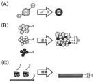
図2(A)に示すように、第1工程S1においては、黒鉛とチタン酸リチウムとから選ばれる少なくとも1種の材料1にリチウムをドープしてプレドープ材2を得る。
1.1. First Step As shown in FIG. 2A, in the first step S1, at least one
1.1.1.材料1
材料1は、黒鉛とチタン酸リチウム(LTO)とから選ばれる少なくとも1種からなる。黒鉛やチタン酸リチウムはいずれもリチウムを吸蔵及び放出可能な材料であり、リチウムイオン電池の負極活物質として知られている。黒鉛とLTOとを比較した場合、黒鉛が好ましい。黒鉛は負極電位が低く、本開示の技術による効果がより顕著となるためである。また、黒鉛のほうが容量が大きいためである。また、黒鉛は導電助剤としても高い性能を発揮し得るためである。黒鉛は人造黒鉛であっても天然黒鉛であってもよい。チタン酸リチウムの組成は特に限定されるものではないが、例えばLi4Ti5O12が好ましい。材料1の形状は特に限定されるものではないが、特に粒子状であることが好ましい。
1.1.1.
1.1.2.リチウムのドープ方法
材料1にリチウムをドープしてプレドープ材2を得る方法については様々な方法を採用可能である。例えば、材料1とリチウム源とを物理的に混合することで材料1にリチウムをドープする方法や、材料1にリチウムを電気化学的に挿入する方法等が挙げられる。材料1へのリチウムのドープ量を容易に制御可能である観点からは、リチウムイオン電池における電気化学反応を利用して材料1にリチウムをドープすることが好ましい。例えば、材料1と、材料1よりも貴な電位にてリチウムイオンを充放電する正極活物質と、リチウムイオン伝導性を有する適当な電解質と、を組み合わせてリチウムイオン電池を構成し、当該リチウムイオン電池における充電反応を利用して、材料1にリチウムをドープすることが好ましい。この場合に用いるリチウムイオン電池は液系電池であっても固体電池であってもよい。特に、材料1にリチウムをドープした後でプレドープ材2を容易に分離可能である観点等から、液系電池(非水電解液系電池や水系電池)を用いることが好ましい。すなわち、材料1と、材料1よりも貴な電位にてリチウムイオンを充放電する正極活物質と、リチウムイオン伝導性を有する電解質(例えばLiPF6等)と、当該電解質を溶解させるための溶媒(水や有機溶媒)とを組み合わせて液系のリチウムイオン電池を構成し、当該リチウムイオン電池における充電反応を利用して、材料1にリチウムをドープすることが好ましい。リチウムイオン電池における電気化学反応を利用して材料1にリチウムをドープした後は、例えば、リチウムイオン電池を解体してプレドープ材2を剥ぎ取り、必要に応じてプレドープ材2の洗浄や粉砕を行う。
11.2. Lithium Doping Method Various methods can be adopted for the method of doping the
材料1へのリチウムのドープ量については特に限定されるものではない。材料1へのリチウムのドープ量を増加させるほど、後述する負極合材5におけるプレドープ材2の量を少なくすることができるものと考えられる。リチウムイオン電池における充電反応を利用して材料1にリチウムをドープする場合は、充電量が10mAh/g以上となるまで、材料1中にリチウムをドープすることが好ましい。より好ましくは50mAh/g以上、さらに好ましくは80mAh/g以上、特に好ましくは100mAh/g以上である。上限は特に限定されず、好ましくは200mAh/g以下、より好ましくは180mAh/g以下、さらに好ましくは150mAh/g以下である。或いは、リチウムイオン電池における充電反応を利用して材料1にリチウムをドープする場合は、SOCが好ましくは5%以上となるまで、より好ましくは8%以上となるまで、さらに好ましくは10%以上となるまで充電することが好ましい。上限は特に限定されず、好ましくはSOCが50%以下となるまで充電する。
The amount of lithium doped into the
1.2.第2工程
図2(B)に示すように、第2工程S2においては、硫化物固体電解質3とシリコン系活物質4とプレドープ材2とを混合して負極合材5を得る。
1.2. Second Step As shown in FIG. 2B, in the second step S2, the sulfide
1.2.1.硫化物固体電解質3
硫化物固体電解質3は、硫化物固体電池の固体電解質として適用される硫化物をいずれも採用可能である。例えば、Li2S-P2S5、Li2S-SiS2、LiI-Li2S-SiS2、LiI-Si2S-P2S5、LiI-LiBr-Li2S-P2S5、LiI-Li2S-P2S5、LiI-Li2O-Li2S-P2S5、LiI-Li2S-P2O5、LiI-Li3PO4-P2S5、Li2S-P2S5-GeS2等が挙げられる。これらの中でも、特に、Li2S-P2S5を含む硫化物固体電解質がより好ましい。硫化物固体電解質3は1種のみを単独で用いてもよいし、2種以上を混合して用いてもよい。第2工程S2において、硫化物固体電解質3の量は特に限定されるものではなく、目的とする電池の性能に応じて適宜決定すればよい。例えば、負極合材5の全体(湿式混合の場合は溶媒を除いた乾燥後の固形分全体、以下同じ)を100質量%として、硫化物固体電解質3の含有量を10質量%以上60質量%以下とすることが好ましい。下限がより好ましくは20質量%以上、上限がより好ましくは50質量%以下である。
1.2.1. Sulfide
As the sulfide
1.2.2.シリコン系活物質4
シリコン系活物質4は、構成元素としてSiを含み、且つ、硫化物固体電池において負極活物質として機能するものであればよい。例えば、Si、Si合金及びケイ素酸化物のうちの少なくとも1種を用いることができる。特にSi又はケイ素酸化物が好ましい。シリコン系活物質4の形状は特に限定されるものではない。例えば、粒子状とすることが好ましい。第2工程S2において、シリコン系活物質4の量は特に限定されるものではなく、目的とする電池の性能に応じて適宜決定すればよい。例えば、負極合材5の全体を100質量%として、シリコン系活物質4の含有量を30質量%以上90質量%以下とすることが好ましい。下限がより好ましくは50質量%以上、上限がより好ましくは80質量%以下である。
1.2.2. Silicon-based
The silicon-based
1.2.3.プレドープ材2
第2工程S2において、プレドープ材2の量は特に限定されるものではなく、第1工程S1におけるリチウムのドープ量等に応じて適宜決定すればよい。特に、第2工程S2においては、負極合材5に含まれるプレドープ材2にドープされたリチウムの総量の容量換算値(X)と、負極合材5に含まれるシリコン系活物質4の総容量(Y)との比(X/Y)が、0.0005以上となるように、プレドープ材2とシリコン系活物質4との混合比を決定することが好ましい。比(X/Y)は0.0008以上であることがより好ましい。本発明者の知見によれば、比(X/Y)が0.0005以上であれば、シリコン系活物質4へと十分な量のリチウムを拡散させることができ、硫化物固体電池100を構成した場合の自己放電を一層抑制可能である。
1.2.3.
In the second step S2, the amount of the
尚、「負極合材5に含まれるプレドープ材2にドープされたリチウムの総量の容量換算値(X)」とは、負極合材5において、プレドープ材2からシリコン系活物質4へと拡散され得るリチウムの総量を容量に換算したものをいう。リチウムイオン電池における充電反応を利用して材料1にリチウムをドープしてプレドープ材2を得た場合、充電量(Ah/g)から容量換算値(X)を求めることができる。「負極合材5に含まれるシリコン系活物質4の総容量(Y)」とは、負極合材5に含まれる未充電状態のシリコン系活物質4が有する容量をいう。具体的には、Yを測定するための合剤を別途用意し、対極Liセルで充放電した際に得られる初回充電容量から得られる活物質充電容量とすることができる。
The "capacity conversion value (X) of the total amount of lithium doped in the
1.2.4.その他の成分
第2工程S2においては、上記課題を解決できる範囲において、負極合材5中にさらに導電助剤を混合することが好ましい。導電助剤は、硫化物固体電池において採用される導電助剤として公知のものをいずれも採用できる。例えば、アセチレンブラック(AB)やケッチェンブラック(KB)や気相法炭素繊維(VGCF)やカーボンナノチューブ(CNT)やカーボンナノファイバー(CNF)や黒鉛等の炭素材料;ニッケル、アルミニウム、ステンレス鋼等の金属材料を用いることができる。特に炭素材料が好ましい。導電助剤は1種のみを単独で用いてもよいし、2種以上を混合して用いてもよい。導電助剤の形状は、粉末状、繊維状等、種々の形状を採用できる。第2工程S2において、導電助剤の量は特に限定されるものではなく、目的とする電池の性能に応じて適宜決定すればよい。例えば、負極合材5の固形分全体を100質量%として、導電助剤の含有量を0.5質量%以上20質量%以下とすることが好ましい。下限がより好ましくは1質量%以上、上限がより好ましくは10質量%以下である。
1.2.4. Other Components In the second step S2, it is preferable to further mix the conductive auxiliary agent in the
第2工程S2においては、上記課題を解決できる範囲において、負極合材5中にさらにバインダーを混合することが好ましい。バインダーは、硫化物固体電池において採用されるバインダーとして公知のものをいずれも採用できる。例えば、スチレンブタジエンゴム(SBR)、カルボキシメチルセルロース(CMC)、アクリロニトリルブタジエンゴム(ABR)、ブタジエンゴム(BR)、ポリフッ化ビニリデン(PVDF)、ポリテトラフルオロエチレン(PTFE)等の中から選ばれる少なくとも1種を用いることができる。第2工程S2において、バインダーの量は特に限定されるものではなく、目的とする電池の性能に応じて適宜決定すればよい。例えば、負極合材5の固形分全体を100質量%として、バインダーの含有量を1質量%以上30質量%以下とすることが好ましい。下限がより好ましくは2質量%以上、上限がより好ましくは15質量%以下である。
In the second step S2, it is preferable to further mix the binder in the
第2工程S2においては、上記課題を解決できる範囲において、負極合材5中にさらに硫化物固体電解質3以外の固体電解質を混合してもよい。例えば、ランタンジルコン酸リチウム、LiPON、Li1+XAlXGe2-X(PO4)3、Li-SiO系ガラス、Li-Al-S-O系ガラス等の酸化物固体電解質等を混合してもよい。
In the second step S2, a solid electrolyte other than the sulfide
第2工程S2においては、上記課題を解決できる範囲において、負極合材5中にさらにシリコン系活物質4以外の負極活物質を混合してもよい。例えば、グラファイトやハードカーボン等の炭素材料;チタン酸リチウム等の各種酸化物;金属リチウムやリチウム合金等を混合してもよい。
In the second step S2, a negative electrode active material other than the silicon-based
1.2.5.混合方法
第2工程S2において、硫化物固体電解質3とシリコン系活物質4とプレドープ材2とを混合して負極合材5とする方法については特に限定されるものではない。公知の混合手段を用いて第2工程S2を実施可能である。第2工程S2における混合は、溶媒を用いた湿式混合であってもよいし、溶媒を用いない乾式混合(粉体同士の混合)であってもよい。材料をより均一に混合でき、プレドープ材2からシリコン系活物質4へとより適切にリチウムを拡散させることが可能である観点からは、溶媒を用いた湿式混合が好ましい。具体的には、硫化物固体電解質3とシリコン系活物質4とプレドープ材2とを溶媒とともに混合し、スラリー状又はペースト状の負極合材5を得ることが好ましい。この場合に用いられる溶媒の種類は特に限定されるものではない。例えば酪酸ブチルやN-メチルピロリドン(NMP)を用いることが好ましい。
1.2.5. Mixing Method In the second step S2, the method of mixing the sulfide
1.3.第3工程
図2(C)に示すように、第3工程S3においては、銅を含む負極集電体6の表面に負極合材5を積層して負極10を得る。
1.3. Third Step As shown in FIG. 2C, in the third step S3, the
1.3.1.銅を含む負極集電体6
負極集電体6は銅を含むものであればよい。例えば、銅又は銅合金を含む金属箔や金属メッシュが挙げられる。或いは、基材に銅又は銅合金をめっき、蒸着したものであってもよい。特に銅からなる金属箔(銅箔)が好ましい。負極集電体6の厚みは特に限定されるものではない。例えば0.1μm以上1mm以下であることが好ましく、1μm以上100μm以下であることがより好ましい。
1.3.1. Negative current
The negative electrode
1.3.2.積層方法
負極集電体6の表面への負極合材5の積層方法は特に限定されるものではない。負極集電体6の表面に負極合材5を湿式で塗布したうえで乾燥し、任意に加圧成形することで、負極集電体6の表面に負極合材5を積層してもよいし、負極集電体6とともに負極合材5を乾式で加圧成形することで、負極集電体6の表面に負極合材5を形成してもよい。湿式の場合は上述の通り負極合材5を溶媒に分散させる等してスラリー又はペーストとすることが好ましい。尚、第3工程S3において加圧成形を行う場合、負極合材5において硫化物固体電解質3とシリコン系活物質4とプレドープ材2との接触がより良好となることから、プレドープ材2からシリコン系活物質4へとより均一にリチウムを拡散させることができ、より顕著な効果を発揮できるものと考えられる。
1.3.2. Laminating method The laminating method of the
第3工程S3を経て負極集電体6の表面に積層された負極合材5の層の厚み(湿式の場合は溶媒を除いた乾燥後の厚み)は特に限定されるものではない。例えば0.1μm以上1mm以下であることが好ましく、1μm以上100μm以下であることがより好ましい。或いは、高容量化のため、これよりも厚くすることも可能である。尚、負極10の容量が正極20の容量よりも大きくなるように、負極合材5の層の厚みを決定することが好ましい。
The thickness of the layer of the
以上の通り、工程S1~S3を経ることで、硫化物固体電池100の負極10を製造することができる。尚、負極10においては、負極合材5の層の負極集電体6とは反対側の面(電池とした場合に正極側となる面)に、さらに負極合材5とは異なる負極合材の層が設けられていてもよい。例えば、負極活物質としてシリコン系活物質以外の活物質(例えば炭素系活物質)のみを含む層等である。
As described above, the negative electrode 10 of the sulfide solid-
1.4.補足
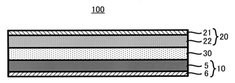
図3に示すように、硫化物固体電池100は上記の工程S1~S3によって製造される負極10のほかに、正極20と固体電解質層30とを備える。正極20や固体電解質層30の製造方法は公知である。すなわち、硫化物固体電池100は、製造方法S10を備えることを除き、従来と同様の方法により製造可能である。
1.4. Supplement As shown in FIG. 3, the sulfide solid-
1.4.1.正極20
硫化物固体電池100における正極20の構成は当業者にとって自明であるが、以下、一例について説明する。正極20は、通常、正極活物質と、任意成分として固体電解質、バインダー、導電助剤及びその他添加剤(増粘剤等)とを含む正極合材層22を備える。また、当該正極合材層22と接触する正極集電体21を備えることが好ましい。
1.4.1. Positive electrode 20
The configuration of the positive electrode 20 in the sulfide solid-
正極集電体21は、金属箔や金属メッシュ等により構成すればよい。特に金属箔が好ましい。正極集電体を構成し得る金属としては、ステンレス鋼、ニッケル、クロム、金、白金、アルミニウム、鉄、チタン、亜鉛等を例示することができる。金属箔や基材にこれらをめっき、蒸着したものであってもよい。 The positive electrode current collector 21 may be formed of a metal foil, a metal mesh, or the like. Metal leaf is particularly preferable. Examples of the metal that can form the positive electrode current collector include stainless steel, nickel, chromium, gold, platinum, aluminum, iron, titanium, zinc, and the like. These may be plated and vapor-deposited on a metal foil or a base material.
正極合材層22に含まれる正極活物質は硫化物固体電池の正極活物質として公知のものをいずれも採用できる。公知の活物質のうち、上記のシリコン系活物質4よりも充放電電位が貴な電位を示す物質を正極活物質とすればよい。例えば、正極活物質としてコバルト酸リチウム、ニッケル酸リチウム、Li(Ni,Mn,Co)O2(Li1+αNi1/3Mn1/3Co-1/3O2)、マンガン酸リチウム、スピネル型リチウム複合酸化物、チタン酸リチウム、リン酸金属リチウム(LiMPO4、MはFe、Mn、Co、Niから選ばれる少なくとも1種)等のリチウム含有酸化物を用いることができる。正極活物質は1種のみを単独で用いてもよいし2種以上を混合して用いてもよい。正極活物質は表面にニオブ酸リチウムやチタン酸リチウムやリン酸リチウム等の被覆層を有していてもよい。正極活物質の形状は特に限定されるものではない。例えば、粒子状や薄膜状とすることが好ましい。正極合材層における正極活物質の含有量は特に限定されるものではなく、従来の硫化物固体電池の正極合材層に含まれる正極活物質の量と同等とすればよい。
As the positive electrode active material contained in the positive electrode mixture layer 22, any known positive electrode active material of the sulfide solid-state battery can be adopted. Among the known active materials, a substance having a charge / discharge potential higher than that of the silicon-based
固体電解質は硫化物固体電池の固体電解質として公知のものをいずれも採用でき、例えば、上記の硫化物固体電解質を採用することが好ましい。ただし、所望の効果を発揮できる範囲で、硫化物固体電解質に加えて、硫化物固体電解質以外の無機固体電解質が含まれていてもよい。導電助剤やバインダーについても、負極10におけるものと同様のものを採用することができる。固体電解質、導電助剤及びバインダーはそれぞれ1種のみを単独で用いてもよいし、2種以上を混合して用いてもよい。固体電解質や導電助剤の形状は特に限定されるものではない。例えば、粒子状とすることが好ましい。正極合材層における固体電解質、導電助剤及びバインダーの含有量は特に限定されるものではなく、従来の硫化物固体電池の正極合材層に含まれる固体電解質、導電助剤及びバインダーの量と同等とすればよい。 As the solid electrolyte, any known solid electrolyte as the solid electrolyte of the sulfide solid battery can be adopted, and for example, it is preferable to adopt the above-mentioned sulfide solid electrolyte. However, an inorganic solid electrolyte other than the sulfide solid electrolyte may be contained in addition to the sulfide solid electrolyte as long as the desired effect can be exhibited. As the conductive auxiliary agent and the binder, the same ones as those in the negative electrode 10 can be adopted. Only one kind of solid electrolyte, conductive auxiliary agent and binder may be used alone, or two or more kinds may be mixed and used. The shape of the solid electrolyte or the conductive auxiliary agent is not particularly limited. For example, it is preferably in the form of particles. The content of the solid electrolyte, the conductive auxiliary agent and the binder in the positive electrode mixture layer is not particularly limited, and is the amount of the solid electrolyte, the conductive auxiliary agent and the binder contained in the positive electrode mixture layer of the conventional sulfide solid-state battery. It should be equivalent.
以上の構成を備える正極20は、正極活物質と、任意に含有させる固体電解質、バインダー及び導電助剤とを溶媒に入れて混練することによりスラリー状の電極組成物を得た後、この電極組成物を正極集電体の表面に塗布し乾燥する等の過程を経ることにより容易に製造することができる。ただし、このような湿式法に限定されるものではなく、乾式にて正極を製造することも可能である。このようにして正極集電体の表面にシート状の正極合剤層を形成する場合、正極合剤層の厚みは、例えば0.1μm以上1mm以下であることが好ましく、1μm以上100μm以下であることがより好ましい。 The positive electrode 20 having the above configuration is obtained by kneading a positive electrode active material with a solid electrolyte, a binder and a conductive auxiliary agent optionally contained in a solvent to obtain a slurry-like electrode composition, and then this electrode composition. It can be easily manufactured by applying a substance to the surface of the positive electrode current collector and drying it. However, the present invention is not limited to such a wet method, and it is also possible to manufacture a positive electrode by a dry method. When the sheet-shaped positive electrode mixture layer is formed on the surface of the positive electrode current collector in this way, the thickness of the positive electrode mixture layer is preferably 0.1 μm or more and 1 mm or less, and is preferably 1 μm or more and 100 μm or less. Is more preferable.
1.4.2.固体電解質層30
硫化物固体電池100における固体電解質層30の構成は当業者にとって自明であるが、以下、一例について説明する。固体電解質層30は、固体電解質と任意にバインダーとを含む。固体電解質は、例えば、上記の硫化物固体電解質を採用することが好ましい。ただし、所望の効果を発揮できる範囲で、硫化物固体電解質に加えて、例えば、硫化物固体電解質以外の無機固体電解質が含まれていてもよい。バインダーは上記したバインダーと同様のものを適宜選択して用いることができる。固体電解質層30における各成分の含有量は従来と同様とすればよい。固体電解質層30の形状も従来と同様とすればよい。特にシート状の固体電解質層30が好ましい。シート状の固体電解質層30は、例えば、固体電解質と任意にバインダーとを溶媒に入れて混練することによりスラリー状の電解質組成物を得た後、この電解質組成物を基材の表面に塗布し乾燥する、或いは、正極合材層及び/又は負極合材層の表面に塗布し乾燥する等の過程を経ることにより容易に製造することができる。この場合、固体電解質層30の厚みは、例えば0.1μm以上300μm以下であることが好ましく、0.1μm以上100μm以下であることがより好ましい。
14.2.
The structure of the
1.4.3.その他の部材
言うまでもないが、硫化物固体電池100は、負極10、正極20及び固体電解質層30の他に、必要な端子や電池ケース等を備えていてもよい。これら部材は公知であり、ここでは詳細な説明を省略する。
1.4.3. Needless to say, the sulfide solid-
1.5.硫化物固体電池100
本開示の製造方法S10を経て製造される硫化物固体電池100は、例えば、以下の通り構造的に特徴付けられる。すなわち、負極10と、正極20と、負極10及び正極20の間に設けられた固体電解質層30とを備え、前記負極10は、銅を含む負極集電体6と、負極集電体6の表面に設けられた負極合材5からなる層を備え、前記負極合材5は、硫化物固体電解質3とシリコン系活物質4とプレドープ材2とを含み、前記プレドープ材2は黒鉛とチタン酸リチウムとからから選ばれる少なくとも1種の材料1(好ましくは黒鉛からなる材料1)にリチウムがドープされたものである、硫化物固体電池100である。各部材の構成については上述した通りであり、ここでは詳細な説明を省略する。
1.5. Sulfide
The sulfide solid-
以上の通り、本開示の製造方法S10においては、第1工程S1において所定のプレドープ材2を準備し、第2工程S2においてシリコン系活物質4とともにプレドープ材2を混合して負極合材5を作製する。この場合、負極合材5を作製した直後にプレドープ材2からシリコン系活物質4へとリチウムが拡散し、負極10とした場合のリチウム標準電位が低下する。すなわち、硫化物固体電解質3と銅(負極集電体6中の銅)との反応を抑制でき、硫化物固体電解質3を介して負極集電体6から正極20側に銅が拡散することを抑制でき、硫化物固体電池100において正極20と負極10との微短絡を原因とする自己放電等を抑制できる。また、プレドープ材2は導電性やイオン伝導性を有したまま負極10中に存在することとなることから、硫化物固体電池100の特性の弊害となり難い。
As described above, in the manufacturing method S10 of the present disclosure, a predetermined
2.本開示の製造方法の優位性について補足
尚、負極活物質として用いるシリコン系活物質に対し、負極合材作製前に、リチウムイオン電池における電気化学反応を利用してリチウムを予めドープしておくことで、同様の効果が得られるものとも考えられる。しかしながら、この場合、上記製造方法S10よりもはるかに多くの量の活物質に対してドープ処理をする必要がある等、コスト面から非現実的と考えられる。
2. 2. Supplementary information on the superiority of the manufacturing method of the present disclosure It should be noted that the silicon-based active material used as the negative electrode active material is pre-doped with lithium by utilizing an electrochemical reaction in a lithium ion battery before preparing the negative electrode mixture. Therefore, it is considered that the same effect can be obtained. However, in this case, it is considered unrealistic from the viewpoint of cost, for example, it is necessary to perform a doping treatment on a much larger amount of active material than the above-mentioned production method S10.
また、負極集電体として銅以外の金属からなるものを用いることで、CuS生成の問題を解決することも考えられる。しかしながら、この場合、サイクル特性等の電池の諸性能が低下する場合がある。 It is also conceivable to solve the problem of CuS generation by using a negative electrode current collector made of a metal other than copper. However, in this case, various performances of the battery such as cycle characteristics may deteriorate.
3.市場でのエビデンス
硫化物固体電池が本開示の製造方法により製造されたものであるのか否かについては、例えば以下の方法で確認することができる。すなわち、硫化物固体電池において、正極及び負極が対向していない部分の負極活物質を解析したり、3極セル化による正負極電位の兼ね合いをみることで、硫化物固体電池が本開示の製造方法により製造されたものであるのか否かを確認することができる。或いは、液系電池における電気化学反応を利用してプレドープ材を得た場合にはプレドープ材の表面にSEIが形成される。そのため、負極に含まれる黒鉛やチタン酸リチウムが表面にSEIを有するか否かを確認することで、硫化物固体電池が本開示の製造方法により製造されたものであるのか否かを確認することもできる。SEIを構成する化合物としては、LiF、LiCO3、リン酸エステル等が挙げられる。SEIを構成する化合物の有無を確認する方法としては、TEM-EELS、ICP、EPSによる元素分析、TOF-SIMSによる質量分析、及びこれらを組み合わせた分析等が挙げられる。例えば、フッ素のように、固体電解質原料には含まれない元素が、プレドープ材表面に形成されたSEIにのみ含まれることを確認することで本実施の有無を判定できる。
3. 3. Evidence on the Market Whether or not the sulfide solid-state battery is manufactured by the manufacturing method of the present disclosure can be confirmed by, for example, the following method. That is, in the sulfide solid-state battery, the sulfide solid-state battery is manufactured according to the present disclosure by analyzing the negative electrode active material in the portion where the positive electrode and the negative electrode do not face each other and by observing the balance between the positive and negative electrode potentials due to the tripolar cell formation. It is possible to confirm whether or not the product is manufactured by the method. Alternatively, when a pre-doped material is obtained by utilizing an electrochemical reaction in a liquid-based battery, SEI is formed on the surface of the pre-doped material. Therefore, by confirming whether or not graphite or lithium titanate contained in the negative electrode has SEI on the surface, it is confirmed whether or not the sulfide solid-state battery is manufactured by the manufacturing method of the present disclosure. You can also. Examples of the compound constituting SEI include LiF, LiCO 3 , and a phosphoric acid ester. Examples of the method for confirming the presence or absence of a compound constituting SEI include elemental analysis by TEM-EELS, ICP and EPS, mass spectrometry by TOF-SIMS, and analysis combining these. For example, the presence or absence of this implementation can be determined by confirming that an element that is not contained in the solid electrolyte raw material, such as fluorine, is contained only in the SEI formed on the surface of the predoped material.
<実施例1>
1.硫化物固体電池の作製
1.1.正極活物質の作製
LiNi1/3Mn1/3Co1/3O2粒子(平均粒子径(D50)6μm)を用意
した。ゾルゲル法により、当該粒子の表面にLiNbO3を被覆した。具体的には、等モルのLiOC2H5及びNb(OC2H5)5を溶解させたエタノール溶液を、上記の粒子の表面に、大気圧下で、転動流動コーティング装置(パウレック社製SFP-01)を用いてコーティングした。コーティングの厚みは5nmになるように処理時間を調整した。その後、コーティング粒子を350℃、大気圧下で1時間に亘って熱処理することで、正極活物質を得た。
<Example 1>
1. 1. Preparation of sulfide solid-state battery 1.1. Preparation of positive electrode active material LiNi 1/3 Mn 1/3 Co 1/3 O 2 particles (average particle diameter (D 50 ) 6 μm) were prepared. The surface of the particles was coated with LiNbO 3 by the sol-gel method. Specifically, an ethanol solution in which equimolar LiOC 2 H 5 and Nb (OC 2 H 5 ) 5 are dissolved is applied to the surface of the above particles under atmospheric pressure under a rolling flow coating device (manufactured by Paulec). It was coated with SFP-01). The treatment time was adjusted so that the thickness of the coating was 5 nm. Then, the coated particles were heat-treated at 350 ° C. under atmospheric pressure for 1 hour to obtain a positive electrode active material.
1.2.正極の作製
得られた正極活物質と、硫化物固体電解質(LiI-Li2O-Li2S-P2S5、平均粒子径(D50)2.5μm)とを、質量比で正極活物質:硫化物固体電解質=75:25となるように秤量し、さらに、正極活物質100質量部に対してPVDF系バインダー(クレハ社製)を4質量部、導電助剤としてアセチレンブラックを6質量部秤量した。これらを酪酸ブチル中に、固形分70質量%となるように調合し、攪拌機で混練して正極ペーストを得た。得られた正極ペーストをアプリケーターによるブレードコート法により、厚さ15μmのアルミニウム箔上に目付量が30mg/cm2となるように塗工し、120℃で3分乾燥することで、アルミニウム箔上に正極合材層を備える正極を得た。
1.2. Preparation of positive electrode The obtained positive electrode active material and the sulfide solid electrolyte (LiI-Li 2 O-Li 2 SP 2 S 5 , average particle size (D 50 ) 2.5 μm) are combined into the positive electrode activity by mass ratio. Material: Weighed so that the sulfide solid electrolyte = 75:25, and further, 4 parts by mass of PVDF-based binder (manufactured by Kureha) and 6 parts by mass of acetylene black as a conductive auxiliary agent with respect to 100 parts by mass of the positive electrode active material. Weighed a part. These were mixed with butyl butyrate so as to have a solid content of 70% by mass, and kneaded with a stirrer to obtain a positive electrode paste. The obtained positive electrode paste is applied onto an aluminum foil having a thickness of 15 μm by a blade coating method using an applicator so as to have a basis weight of 30 mg / cm 2 , and dried at 120 ° C. for 3 minutes onto the aluminum foil. A positive electrode provided with a positive electrode mixture layer was obtained.
1.3.固体電解質層の作製
上記と同様の硫化物固体電解質を95質量部、バインダーとしてブチレンゴムを5質量部それぞれ秤量し、これらをヘプタン溶媒中に固形分70質量%となるように調合し、超音波分散装置(エスエムテー社製UH-50)を用いて2分間攪拌し、固体電解質ペーストを得た。得られた固体電解質ペーストを、正極ペーストの場合と同様の方法にて基材(アルミニウム箔)上に目付量が60mg/cm2となるように塗工し、自然乾燥の後、100℃で30分間乾燥することで、固体電解質層を有する基材を得た。
1.3. Preparation of solid electrolyte layer Weigh 95 parts by mass of the same sulfide solid electrolyte as above and 5 parts by mass of butylene rubber as a binder, mix them in a heptane solvent so that the solid content is 70% by mass, and disperse the ultrasonic waves. The mixture was stirred for 2 minutes using an apparatus (UH-50 manufactured by SMT) to obtain a solid electrolyte paste. The obtained solid electrolyte paste is applied onto a base material (aluminum foil) in the same manner as in the case of the positive electrode paste so that the grain size is 60 mg / cm 2 , and after natural drying, it is 30 at 100 ° C. After drying for a minute, a substrate having a solid electrolyte layer was obtained.
1.4.負極の作製
1.4.1.プレドープ材の作製
天然黒鉛の微粒子(平均粒子径(D50)15μm)99.7質量部と、カルボキシメチルセルロース0.3質量部とをそれぞれ秤量し、これらをイオン交換水中に固形分60質量%となるように調合し、プラネタリーミキサーにより混練してペーストを得た。得られたペーストを銅箔上にブレードコート法により均一に塗布し、120℃で5分間乾燥させて電極を得た。得られた電極をφ16mmに打ち抜き、対極としてLi金属、セパレータとして厚み20μmのPE製セパレータ、電解液として非水電解液(ECとDECとの混合溶媒(EC:DEC=1:1)に1mol/kgの濃度でLiPF6-を溶解させたもの)を用いてコインセルを作成した。このコインセルを充放電装置により充電した。充電量は、コインセルに含まれる黒鉛の総重量に対して、100mAh/kgになるように調整した。充電後、コインセルをアルゴン雰囲気下で解体し、電極を取り出し、電極をEMCで洗浄後、銅箔から黒鉛をスパチュラで剥ぎ取り、プレドープ材を得た。
1.4. Fabrication of negative electrode 1.4.1. Preparation of pre-doped material 99.7 parts by mass of natural graphite fine particles (average particle size (D 50 ) 15 μm) and 0.3 parts by mass of carboxymethyl cellulose were weighed, and these were added to ion-exchanged water to a solid content of 60% by mass. And kneaded with a planetary mixer to obtain a paste. The obtained paste was uniformly applied onto a copper foil by a blade coating method and dried at 120 ° C. for 5 minutes to obtain an electrode. The obtained electrode was punched to φ16 mm, Li metal as a counter electrode, a PE separator having a thickness of 20 μm as a separator, and 1 mol / mol / in a non-aqueous electrolyte solution (mixed solvent of EC and DEC (EC: DEC = 1: 1)) as an electrolytic solution. A coin cell was prepared using LiPF 6- dissolved at a concentration of kg). This coin cell was charged by a charging / discharging device. The charge amount was adjusted to be 100 mAh / kg with respect to the total weight of graphite contained in the coin cell. After charging, the coin cell was disassembled in an argon atmosphere, the electrodes were taken out, the electrodes were washed with EMC, and graphite was stripped from the copper foil with a spatula to obtain a pre-doped material.
1.4.2.負極合材の作製及び銅箔への積層
上記の硫化物固体電解質と、シリコンの微粒子(平均粒子径(D50)6μm)と、プレドープ材とを、質量比で硫化物固体電解質:シリコンの微粒子:プレドープ材=45:53.4:1.6(シリコン系活物質:プレドープ材=97:3)となるように秤量し、さらに、シリコンの微粒子100質量部に対してPVDF系バインダー(クレハ社製)を6質量部、導電助剤としてアセチレンブラックを6質量部秤量した。これらを酪酸ブチル中に、固形分70質量%となるように調合し、攪拌機で混練してペースト状の負極合材を得た。得られたペーストをアプリケーターによるブレードコート法により、厚さ15μmの銅箔上に均一に塗工し、120℃で3分乾燥することで、銅箔上に負極合材層を備える負極を得た。
14.2. Preparation of negative electrode mixture and lamination on copper foil The above sulfide solid electrolyte, silicon fine particles (average particle diameter (D 50 ) 6 μm), and pre-doped material are mixed by mass ratio of sulfide solid electrolyte: silicon fine particles. : Pre-doped material = 45: 53.4: 1.6 (silicon-based active material: pre-doped material = 97: 3), and further, PVDF-based binder (Kureha Co., Ltd.) with respect to 100 parts by mass of fine particles of silicon. Weighed 6 parts by mass and 6 parts by mass of acetylene black as a conductive auxiliary agent. These were mixed with butyl butyrate so as to have a solid content of 70% by mass, and kneaded with a stirrer to obtain a paste-like negative electrode mixture. The obtained paste was uniformly applied onto a copper foil having a thickness of 15 μm by a blade coating method using an applicator, and dried at 120 ° C. for 3 minutes to obtain a negative electrode having a negative electrode mixture layer on the copper foil. ..
1.5.正極、固体電解質層及び負極の積層
上記の固体電解質層を面積1cm2に打ち抜き、1ton/cm2でプレスした。プレスした固体電解質層の一方の面(基材とは反対側の面)に上記の正極を重ねて1ton/cm2でプレスした。基材を剥がし、その面に上記の負極を重ねて6ton/cm2でプレスして正極/固体電解質層/負極からなる積層体を得た。得られた積層体を端子付のアルミニウムラミネートフィルム中に密閉し、評価用の硫化物固体電池を得た。得られた電池の仕様を下記表1に示す。
1.5. Lamination of Positive Electrode, Solid Electrolyte Layer and Negative Electrode The above solid electrolyte layer was punched into an area of 1 cm 2 and pressed at 1 ton / cm 2 . The above positive electrode was placed on one surface of the pressed solid electrolyte layer (the surface opposite to the substrate) and pressed at 1 ton / cm 2 . The base material was peeled off, and the above negative electrode was placed on the surface thereof and pressed at 6 ton / cm 2 to obtain a laminate composed of a positive electrode / a solid electrolyte layer / a negative electrode. The obtained laminate was sealed in an aluminum laminate film with terminals to obtain a sulfide solid-state battery for evaluation. The specifications of the obtained battery are shown in Table 1 below.
2.硫化物固体電池の自己放電検査
上述したように負極集電体である銅箔が硫化物固体電解質と反応すると導電性の高いCuSとなって負極集電体から正極側にCuが拡散し、正極と負極との微短絡が生じて、硫化物固体電池の電圧が自己的に降下する場合がある。これを評価するため、次の手順により硫化物固体電池の自己放電検査を行った。すなわち、まず、硫化物固体電池を充電した後(充電条件:4.4cccv、電流レート2mA、カットオフ電流0.1mA)、25℃の恒温槽で25時間静置し、静置中の電圧ΔVを測定した。結果を下記表1に示す。
2. 2. Self-discharge inspection of solid-state sulfide battery As described above, when the copper foil, which is the negative electrode current collector, reacts with the solid sulfide electrolyte, it becomes CuS with high conductivity, and Cu diffuses from the negative electrode current collector to the positive electrode side, and the positive electrode A slight short circuit between the electrode and the negative electrode may occur, and the voltage of the sulfide solid-state battery may drop by itself. To evaluate this, a self-discharge test was performed on the sulfide solid-state battery according to the following procedure. That is, first, after charging the sulfide solid-state battery (charging conditions: 4.4 cccv,
3.サイクル特性評価
負極活物質としてシリコン系活物質のみを用いる場合と比べて、シリコン系活物質とともに炭素系活物質を用いる場合、充放電時、負極活物質全体としての膨張率が緩和され、硫化物固体電池のサイクル特性が向上することが期待される。この効果を確認するため、以下の条件でサイクル試験を行った。初回の放電容量に対する150サイクル後の放電容量を容量維持率[%]として計算した。尚、このサイクル試験は、ロードセル付の拘束治具により、正負極電極面に均一に5MPaの圧力がかかるように拘束しながら行った。結果を下記表1に示す。
(サイクル試験条件)
充電:4.4Vcccv、電流レート10mA、カットオフ電流0.5mA
放電:3.0Vcc、電流レート10mA
温度:25℃
3. 3. Cycle characteristics evaluation Compared to the case where only the silicon-based active material is used as the negative electrode active material, when the carbon-based active material is used together with the silicon-based active material, the expansion rate of the negative electrode active material as a whole is relaxed during charging and discharging, and the sulfide is used. It is expected that the cycle characteristics of solid-state batteries will be improved. To confirm this effect, a cycle test was conducted under the following conditions. The discharge capacity after 150 cycles with respect to the initial discharge capacity was calculated as the capacity retention rate [%]. This cycle test was performed while restraining the positive and negative electrode surfaces with a restraining jig equipped with a load cell so that a pressure of 5 MPa was uniformly applied. The results are shown in Table 1 below.
(Cycle test conditions)
Charging: 4.4Vcccv, current rate 10mA, cutoff current 0.5mA
Discharge: 3.0Vcc, current rate 10mA
Temperature: 25 ° C
<実施例2~4、比較例1>
負極活物質とプレドープ材との混合比を下記表1のように変更したこと以外は、実施例1と同様にして硫化物固体電池を作製し、自己放電検査及びサイクル特性評価を行った。電池の仕様、自己放電検査結果及びサイクル特性評価結果を下記表1に示す。
<Examples 2 to 4, Comparative Example 1>
A sulfide solid-state battery was produced in the same manner as in Example 1 except that the mixing ratio of the negative electrode active material and the pre-doped material was changed as shown in Table 1 below, and self-discharge inspection and cycle characteristic evaluation were performed. Table 1 below shows the battery specifications, self-discharge inspection results, and cycle characteristic evaluation results.
<実施例5>
プレドープ材を作製する際の充電量を150mAh/gに変更したこと以外は、実施例1と同様にして硫化物固体電池を作製し、自己放電検査及びサイクル特性評価を行った。電池の仕様、自己放電検査結果及びサイクル特性評価結果を下記表1に示す。
<Example 5>
A sulfide solid-state battery was produced in the same manner as in Example 1 except that the charge amount when producing the pre-doped material was changed to 150 mAh / g, and self-discharge inspection and cycle characteristic evaluation were performed. Table 1 below shows the battery specifications, self-discharge inspection results, and cycle characteristic evaluation results.
<実施例6>
プレドープ材として使用する材料を黒鉛からチタン酸リチウム(平均粒子径(D50)2μm)に変更し、以下の手順でプレドープ材を得たこと以外は、実施例1と同様にして硫化物固体電池を作製し、自己放電検査及びサイクル特性評価を行った。電池の仕様、自己放電検査結果及びサイクル特性評価結果を下記表1に示す。
<Example 6>
The sulfide solid-state battery is the same as in Example 1 except that the material used as the pre-doped material is changed from graphite to lithium titanate (average particle size (D 50 ) 2 μm) and the pre-doped material is obtained by the following procedure. Was prepared, and self-discharge inspection and cycle characteristic evaluation were performed. Table 1 below shows the battery specifications, self-discharge inspection results, and cycle characteristic evaluation results.
チタン酸リチウム92質量部と、PVDF系バインダー3質量部と、アセチレンブラック5質量部とをそれぞれ秤量し、これらをNMP中に固形分70質量%となるように調合し、プラネタリーミキサーにより混練してペーストを得た。得られたペーストを、実施例1と同様にブレードコート法により銅箔上に塗布して乾燥させて電極を得た。得られた電極を用いて、実施例1と同様にコインセルを作製し、実施例5と同様に充電(充電量150mAh/g)し、実施例1と同様にコインセルの解体、銅箔からの剥ぎ取りを行った後、剥ぎ取った粉をその体積の約10倍のNMPに分散させて遠心分離することを3回繰り返すことにより、チタン酸リチウムに付着したPVDF系バインダーなどを取り除いた。遠心分離後に得られる微粒子をプレドープ材とした。 Weigh 92 parts by mass of lithium titanate, 3 parts by mass of PVDF binder, and 5 parts by mass of acetylene black, mix them in NMP so that the solid content is 70% by mass, and knead them with a planetary mixer. I got the paste. The obtained paste was applied onto a copper foil by a blade coating method in the same manner as in Example 1 and dried to obtain an electrode. Using the obtained electrodes, a coin cell was produced in the same manner as in Example 1, charged in the same manner as in Example 5 (charge amount 150 mAh / g), and the coin cell was disassembled and peeled from the copper foil in the same manner as in Example 1. After the removal, the stripped powder was dispersed in NMP having about 10 times its volume and centrifuged repeatedly three times to remove the PVDF-based binder and the like adhering to lithium titanate. The fine particles obtained after centrifugation were used as a pre-doped material.
<実施例7>
シリコンに替えてケイ素酸化物(平均粒子径(D50)5μm)に変更し、負極の目付け量を変更したこと以外は、実施例1と同様にして硫化物固体電池を作製し、自己放電検査及びサイクル特性評価を行った。電池の仕様、自己放電検査結果及びサイクル特性評価結果を下記表1に示す。
<Example 7>
A sulfide solid-state battery was produced in the same manner as in Example 1 except that silicon oxide (average particle diameter (D 50 ) 5 μm) was changed instead of silicon and the amount of the negative electrode was changed, and self-discharge inspection was performed. And cycle characteristics were evaluated. Table 1 below shows the battery specifications, self-discharge inspection results, and cycle characteristic evaluation results.
<実施例8>
プレドープ材を作製する際の充電量を10mAh/gに変更し、且つ、負極活物質とプレドープ材との混合比を下記表1のように変更したこと以外は、実施例1と同様にして硫化物固体電池を作製し、自己放電検査及びサイクル特性評価を行った。電池の仕様、自己放電検査結果及びサイクル特性評価結果を下記表1に示す。
<Example 8>
Sulfuration in the same manner as in Example 1 except that the charge amount when producing the pre-doped material was changed to 10 mAh / g and the mixing ratio of the negative electrode active material and the pre-doped material was changed as shown in Table 1 below. A solid-state battery was manufactured, and self-discharge inspection and cycle characteristic evaluation were performed. Table 1 below shows the battery specifications, self-discharge inspection results, and cycle characteristic evaluation results.
<比較例2>
負極集電体として銅箔に替えて同じ厚みのステンレス鋼箔を用いたこと以外は、比較例1と同様にして硫化物固体電池を作製し、自己放電検査及びサイクル特性評価を行った。電池の仕様、自己放電検査結果及びサイクル特性評価結果を下記表1に示す。
<Comparative Example 2>
A sulfide solid-state battery was produced in the same manner as in Comparative Example 1 except that a stainless steel foil having the same thickness was used instead of the copper foil as the negative electrode current collector, and self-discharge inspection and cycle characteristic evaluation were performed. Table 1 below shows the battery specifications, self-discharge inspection results, and cycle characteristic evaluation results.
<参考例1>
負極集電体として銅箔に替えて同じ厚みのステンレス鋼箔を用いたこと以外は、実施例1と同様にして硫化物固体電池を作製し、自己放電検査及びサイクル特性評価を行った。電池の仕様、自己放電検査結果及びサイクル特性評価結果を下記表1に示す。
<Reference example 1>
A sulfide solid-state battery was produced in the same manner as in Example 1 except that a stainless steel foil having the same thickness was used instead of the copper foil as the negative electrode current collector, and self-discharge inspection and cycle characteristic evaluation were performed. Table 1 below shows the battery specifications, self-discharge inspection results, and cycle characteristic evaluation results.
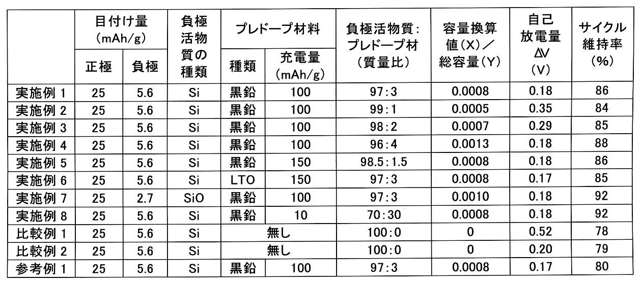
表1に示す結果から明らかなように、負極合材中にプレドープ材を含ませることで、自己放電量が顕著に低下している。プレドープ材により硫化物固体電池の初期の負極電位が低下し、銅箔と硫化物固体電解質との反応が抑制されたものと考えられる。負極合材に含ませるプレドープ材の量は特に限定はなく、負極合材中にプレドープ材がわずかでも含まれていれば一定の効果が発揮されるが、実施例1~8からすると、負極合材に含まれるプレドープ材にドープされたリチウムの総量の容量換算値(X)と、負極合材に含まれるシリコン系活物質の総容量(Y)との比(X/Y)が0.0005以上であることが好ましいといえる。特に、X/Yが0.0008以上である場合、自己放電量が0.18V程度に抑えられたところで自己放電抑制効果が飽和する。或いは、実施例1~8からすると、負極活物質とプレドープ材との合計を100質量%として、負極活物質を70質量%以上100質量%未満、プレドープ材を0質量%超30質量%以下とすることが好ましい。負極容量等を考慮した場合は、例えば、負極活物質をより好ましくは90質量%以上、さらに好ましくは93質量%以上、特に好ましくは96質量%以上とすることができ、プレドープ材をより好ましくは10質量%以下、さらに好ましくは7質量%以下、特に好ましくは4質量%以下とすることができる。
また、実施例1~8及び比較例1の結果から明らかなように、負極集電体として銅箔を用いた場合、負極合材中にプレドープ材を含ませることで、硫化物固体電池のサイクル特性が向上する。
さらに、実施例6及び7の結果から明らかなように、負極活物質の種類やプレドープ材の種類を変更した場合でも同様の効果が得られる。
As is clear from the results shown in Table 1, the amount of self-discharge is significantly reduced by including the pre-doped material in the negative electrode mixture. It is considered that the pre-doped material lowered the initial negative potential of the sulfide solid-state battery and suppressed the reaction between the copper foil and the sulfide solid electrolyte. The amount of the pre-doped material contained in the negative electrode mixture is not particularly limited, and if the negative electrode mixture contains even a small amount of the pre-doped material, a certain effect is exhibited. However, from Examples 1 to 8, the negative electrode mixture is used. The ratio (X / Y) of the capacity conversion value (X) of the total amount of lithium doped in the pre-doped material contained in the material to the total capacity (Y) of the silicon-based active material contained in the negative electrode mixture is 0.0005. It can be said that the above is preferable. In particular, when X / Y is 0.0008 or more, the self-discharge suppressing effect is saturated when the self-discharge amount is suppressed to about 0.18V. Alternatively, according to Examples 1 to 8, the total of the negative electrode active material and the pre-doped material is 100% by mass, the negative electrode active material is 70% by mass or more and less than 100% by mass, and the pre-doped material is more than 0% by mass and 30% by mass or less. It is preferable to do so. When the negative electrode capacity and the like are taken into consideration, for example, the negative electrode active material can be more preferably 90% by mass or more, further preferably 93% by mass or more, particularly preferably 96% by mass or more, and the pre-doped material is more preferably. It can be 10% by mass or less, more preferably 7% by mass or less, and particularly preferably 4% by mass or less.
Further, as is clear from the results of Examples 1 to 8 and Comparative Example 1, when a copper foil is used as the negative electrode current collector, the cycle of the sulfide solid-state battery is formed by including the pre-doped material in the negative electrode mixture. The characteristics are improved.
Further, as is clear from the results of Examples 6 and 7, the same effect can be obtained even when the type of the negative electrode active material or the type of the pre-doped material is changed.
尚、比較例2及び参考例1のように、負極集電体の材質を銅以外の金属(ステンレス鋼等)に変更することによっても、CuSの生成を回避でき、自己放電量が低下する。しかしながら、この場合、自己放電量以外の電池の諸性能が低下する。例えば、比較例2に示すように電池のサイクル特性が低下する。尚、比較例2及び参考例1の結果から明らかなように、負極集電体としてステンレス鋼箔を用いた場合、負極合材中にプレドープ材を含ませたとしてもサイクル特性は向上し難い。ステンレス鋼箔は銅箔と比べて硬質であり、充放電時の負極活物質の膨張収縮に追従し難いためと考えられる。
以上のことから、負極集電体の表面にシリコン系活物質と硫化物固体電解質とを含む負極合材層を設ける場合、銅以外の材質からなる負極集電体を用いてCuSの生成を回避するよりも、銅を含む負極集電体を用いたうえで負極合材中に所定のプレドープ材を含ませてCuSの生成を抑制するほうが優位といえる。
By changing the material of the negative electrode current collector to a metal other than copper (stainless steel or the like) as in Comparative Example 2 and Reference Example 1, the generation of CuS can be avoided and the self-discharge amount is reduced. However, in this case, various performances of the battery other than the self-discharge amount are deteriorated. For example, as shown in Comparative Example 2, the cycle characteristics of the battery are deteriorated. As is clear from the results of Comparative Example 2 and Reference Example 1, when a stainless steel foil is used as the negative electrode current collector, it is difficult to improve the cycle characteristics even if the pre-doped material is contained in the negative electrode mixture. It is considered that the stainless steel foil is harder than the copper foil and it is difficult to follow the expansion and contraction of the negative electrode active material during charging and discharging.
From the above, when a negative electrode mixture layer containing a silicon-based active material and a sulfide solid electrolyte is provided on the surface of the negative electrode current collector, the generation of CuS is avoided by using a negative electrode current collector made of a material other than copper. It can be said that it is more advantageous to suppress the formation of CuS by using a negative electrode current collector containing copper and then including a predetermined pre-doped material in the negative electrode mixture.
本開示の製造方法により製造される硫化物固体電池は、例えば、携帯機器用の小型電源から車搭載用の大型電源まで、広く利用できる。 The sulfide solid-state battery manufactured by the manufacturing method of the present disclosure can be widely used, for example, from a small power source for mobile devices to a large power source for mounting on a car.
10 負極
1 黒鉛及び/又はチタン酸リチウムからなる材料
2 プレドープ材
3 硫化物固体電解質
4 シリコン系活物質
5 負極合材
6 負極集電体
20 正極
21 正極集電体
22 正極合材層
30 固体電解質層
100 硫化物固体電池
10
Claims (3)
硫化物固体電解質とシリコン系活物質と前記プレドープ材とを混合して負極合材を得る、
第2工程、及び、
銅を含む負極集電体の表面に前記負極合材を積層して負極を得る、第3工程、
を備える、硫化物固体電池の製造方法。 First step, in which at least one material selected from graphite and lithium titanate is doped with lithium to obtain a pre-doped material.
A sulfide solid electrolyte, a silicon-based active material, and the pre-doped material are mixed to obtain a negative electrode mixture.
Second step and
A third step of laminating the negative electrode mixture on the surface of a negative electrode current collector containing copper to obtain a negative electrode.
A method for manufacturing a sulfide solid-state battery.
請求項1に記載の製造方法。 The ratio (X /) of the capacity conversion value (X) of the total amount of lithium doped in the pre-doped material contained in the negative electrode mixture to the total capacity (Y) of the silicon-based active material contained in the negative electrode mixture. Y) is 0.0005 or more.
The manufacturing method according to claim 1.
請求項1又は2に記載の製造方法。 In the first step, the material is doped with lithium by utilizing an electrochemical reaction in a lithium ion battery.
The manufacturing method according to claim 1 or 2.
Priority Applications (6)
| Application Number | Priority Date | Filing Date | Title |
|---|---|---|---|
| CN201811186908.0A CN109904523B (en) | 2017-12-08 | 2018-10-12 | Method for manufacturing sulfide solid-state battery |
| EP18201910.9A EP3496188B1 (en) | 2017-12-08 | 2018-10-23 | Method for producing sulfide solid-state battery |
| US16/181,845 US11075366B2 (en) | 2017-12-08 | 2018-11-06 | Method for producing sulfide solid-state battery |
| RU2018141428A RU2695127C1 (en) | 2017-12-08 | 2018-11-26 | Method of producing sulphide solid-state batteries |
| KR1020180150155A KR102165762B1 (en) | 2017-12-08 | 2018-11-28 | Method for producing sulfide solid-state battery |
| BR102018074749-5A BR102018074749A2 (en) | 2017-12-08 | 2018-11-29 | METHOD FOR PRODUCING A SULFET SOLID STATE BATTERY |
Applications Claiming Priority (2)
| Application Number | Priority Date | Filing Date | Title |
|---|---|---|---|
| JP2017236384 | 2017-12-08 | ||
| JP2017236384 | 2017-12-08 |
Publications (2)
| Publication Number | Publication Date |
|---|---|
| JP2019106352A JP2019106352A (en) | 2019-06-27 |
| JP6996414B2 true JP6996414B2 (en) | 2022-01-17 |
Family
ID=67061430
Family Applications (1)
| Application Number | Title | Priority Date | Filing Date |
|---|---|---|---|
| JP2018087219A Active JP6996414B2 (en) | 2017-12-08 | 2018-04-27 | Manufacturing method of sulfide solid-state battery |
Country Status (5)
| Country | Link |
|---|---|
| JP (1) | JP6996414B2 (en) |
| KR (1) | KR102165762B1 (en) |
| CN (1) | CN109904523B (en) |
| BR (1) | BR102018074749A2 (en) |
| RU (1) | RU2695127C1 (en) |
Cited By (1)
| Publication number | Priority date | Publication date | Assignee | Title |
|---|---|---|---|---|
| JP2023177078A (en) * | 2022-06-01 | 2023-12-13 | トヨタ自動車株式会社 | Electrode mixture, electrode active material layer, and lithium ion battery |
Families Citing this family (9)
| Publication number | Priority date | Publication date | Assignee | Title |
|---|---|---|---|---|
| JP7590124B2 (en) * | 2020-05-28 | 2024-11-26 | マクセル株式会社 | Anode for all-solid-state secondary battery, method for producing same and all-solid-state secondary battery |
| CN111908437A (en) * | 2020-08-21 | 2020-11-10 | 中南大学 | Preparation method of sulfide solid electrolyte |
| JP7484683B2 (en) * | 2020-12-03 | 2024-05-16 | トヨタ自動車株式会社 | All-solid-state battery |
| CN115411219A (en) * | 2021-05-28 | 2022-11-29 | 国联汽车动力电池研究院有限责任公司 | Negative plate and preparation method and application thereof |
| JP7582135B2 (en) * | 2021-09-13 | 2024-11-13 | トヨタ自動車株式会社 | Coated negative electrode active material and all-solid-state battery |
| CN113972379B (en) * | 2021-11-02 | 2023-01-10 | 北京科技大学 | A method for preparing copper foil using solid electrolyte and copper foil thereof |
| JP7545429B2 (en) | 2022-02-07 | 2024-09-04 | トヨタ自動車株式会社 | Negative electrode layer |
| CN115995600B (en) * | 2023-03-22 | 2023-08-15 | 中国科学院宁波材料技术与工程研究所 | An element-doped sulfide solid electrolyte with a coating layer and its preparation method |
| WO2025229981A1 (en) * | 2024-04-30 | 2025-11-06 | 日鉄ケミカル&マテリアル株式会社 | Stainless steel foil, electrode, and battery |
Citations (2)
| Publication number | Priority date | Publication date | Assignee | Title |
|---|---|---|---|---|
| JP2017037748A (en) | 2015-08-07 | 2017-02-16 | 日立化成株式会社 | Negative electrode for lithium ion secondary battery and lithium ion secondary battery using the same |
| JP2017054720A (en) | 2015-09-10 | 2017-03-16 | トヨタ自動車株式会社 | Negative electrode for all-solid battery |
Family Cites Families (13)
| Publication number | Priority date | Publication date | Assignee | Title |
|---|---|---|---|---|
| US5595837A (en) * | 1995-04-12 | 1997-01-21 | Valence Technology, Inc. | Process for prelithiation of carbon based anodes for lithium batteries |
| JP2007227328A (en) * | 2006-01-24 | 2007-09-06 | Sanyo Electric Co Ltd | Negative electrode for lithium secondary battery, method of manufacturing the electrode, and lithium secondary battery |
| JP5659696B2 (en) * | 2009-12-24 | 2015-01-28 | ソニー株式会社 | Lithium ion secondary battery, negative electrode for lithium ion secondary battery, electric tool, electric vehicle and power storage system |
| WO2014156638A1 (en) | 2013-03-26 | 2014-10-02 | 古河電気工業株式会社 | All-solid-state secondary battery |
| JP2015032355A (en) * | 2013-07-31 | 2015-02-16 | 日本碍子株式会社 | All-solid battery |
| KR102272556B1 (en) * | 2013-09-02 | 2021-07-02 | 미츠비시 가스 가가쿠 가부시키가이샤 | Solid-state battery |
| JP6278385B2 (en) * | 2013-11-02 | 2018-02-14 | 国立研究開発法人産業技術総合研究所 | Non-aqueous secondary battery pre-doping method and battery obtained by the pre-doping method |
| JP2015115194A (en) * | 2013-12-11 | 2015-06-22 | 三星電子株式会社Samsung Electronics Co.,Ltd. | All-solid-state secondary battery and method for manufacturing all-solid-state secondary battery |
| JP6666641B2 (en) * | 2013-12-13 | 2020-03-18 | 三星電子株式会社Samsung Electronics Co.,Ltd. | All-solid secondary battery and method for manufacturing all-solid secondary battery |
| US9819019B2 (en) * | 2013-12-13 | 2017-11-14 | Samsung Electronics Co., Ltd. | All solid secondary battery and method of preparing all solid secondary battery |
| WO2016054105A1 (en) * | 2014-09-29 | 2016-04-07 | A123 Systems, LLC | Pre-lithiated silicon anodes with pvdf binder |
| JP6354716B2 (en) * | 2015-09-08 | 2018-07-11 | トヨタ自動車株式会社 | Sulfide solid state battery |
| JP6409794B2 (en) * | 2016-02-18 | 2018-10-24 | トヨタ自動車株式会社 | Method for producing positive electrode mixture, method for producing positive electrode, and method for producing all solid lithium ion secondary battery |
-
2018
- 2018-04-27 JP JP2018087219A patent/JP6996414B2/en active Active
- 2018-10-12 CN CN201811186908.0A patent/CN109904523B/en active Active
- 2018-11-26 RU RU2018141428A patent/RU2695127C1/en active
- 2018-11-28 KR KR1020180150155A patent/KR102165762B1/en active Active
- 2018-11-29 BR BR102018074749-5A patent/BR102018074749A2/en not_active IP Right Cessation
Patent Citations (2)
| Publication number | Priority date | Publication date | Assignee | Title |
|---|---|---|---|---|
| JP2017037748A (en) | 2015-08-07 | 2017-02-16 | 日立化成株式会社 | Negative electrode for lithium ion secondary battery and lithium ion secondary battery using the same |
| JP2017054720A (en) | 2015-09-10 | 2017-03-16 | トヨタ自動車株式会社 | Negative electrode for all-solid battery |
Cited By (2)
| Publication number | Priority date | Publication date | Assignee | Title |
|---|---|---|---|---|
| JP2023177078A (en) * | 2022-06-01 | 2023-12-13 | トヨタ自動車株式会社 | Electrode mixture, electrode active material layer, and lithium ion battery |
| JP7779804B2 (en) | 2022-06-01 | 2025-12-03 | トヨタ自動車株式会社 | Electrode mixture, electrode active material layer, and lithium ion battery |
Also Published As
| Publication number | Publication date |
|---|---|
| CN109904523A (en) | 2019-06-18 |
| KR102165762B1 (en) | 2020-10-14 |
| KR20190068435A (en) | 2019-06-18 |
| RU2695127C1 (en) | 2019-07-22 |
| CN109904523B (en) | 2022-03-15 |
| JP2019106352A (en) | 2019-06-27 |
| BR102018074749A2 (en) | 2019-06-25 |
Similar Documents
| Publication | Publication Date | Title |
|---|---|---|
| JP6996414B2 (en) | Manufacturing method of sulfide solid-state battery | |
| JP6834921B2 (en) | Manufacturing method of sulfide solid-state battery and sulfide solid-state battery | |
| KR101752566B1 (en) | Active material composite particles and lithium battery | |
| US12586812B2 (en) | Method for producing all solid-state battery, and all solid-state battery | |
| CN108844878A (en) | Negative pole piece, method for testing active specific surface area of pole piece and battery | |
| CN105742585A (en) | Methods for forming porous materials | |
| WO2015068268A1 (en) | All-solid-state cell, electrode for all-solid-state cell, and method for manufacturing same | |
| JP2012209161A (en) | Lithium secondary battery | |
| JP5151329B2 (en) | Positive electrode body and lithium secondary battery using the same | |
| JP2011159639A (en) | Electrode body, method for manufacturing the same, and lithium ion secondary battery | |
| JP2018106984A (en) | All-solid-state lithium ion battery | |
| US11075366B2 (en) | Method for producing sulfide solid-state battery | |
| US9088047B2 (en) | Electrode for a lithium battery | |
| JP2019021514A (en) | Negative electrode current collector, negative electrode, and water-based lithium ion secondary battery | |
| JP2020017437A (en) | Sheet-shaped positive electrode composite material for lithium ion secondary battery, method for producing the same, and lithium ion secondary battery | |
| US20220238882A1 (en) | Tragacanth gum (tgc)-based aqueous binder and method for manufacturing battery electrode using same | |
| JP2019012654A (en) | Positive electrode material for non-aqueous electrolyte secondary battery, method for producing the same, and non-aqueous electrolyte secondary battery using the positive electrode material | |
| JP2018195419A (en) | Positive electrode material for nonaqueous electrolyte secondary battery, nonaqueous electrolyte secondary battery arranged by use thereof, and method for manufacturing positive electrode material for nonaqueous electrolyte secondary battery | |
| JP6229563B2 (en) | Negative electrode active material for lithium ion secondary battery and lithium ion secondary battery using the negative electrode active material | |
| JP2018181816A (en) | Lithium ion secondary battery | |
| JP2004296305A (en) | Lithium ion secondary battery | |
| JP2019075355A (en) | All-solid battery | |
| JP2011171177A (en) | Lithium ion secondary battery | |
| JP7180066B2 (en) | sulfide solid state battery | |
| JP2015026463A (en) | Non-aqueous electrolyte secondary battery |
Legal Events
| Date | Code | Title | Description |
|---|---|---|---|
| A621 | Written request for application examination |
Free format text: JAPANESE INTERMEDIATE CODE: A621 Effective date: 20201125 |
|
| A977 | Report on retrieval |
Free format text: JAPANESE INTERMEDIATE CODE: A971007 Effective date: 20211027 |
|
| TRDD | Decision of grant or rejection written | ||
| A01 | Written decision to grant a patent or to grant a registration (utility model) |
Free format text: JAPANESE INTERMEDIATE CODE: A01 Effective date: 20211116 |
|
| A61 | First payment of annual fees (during grant procedure) |
Free format text: JAPANESE INTERMEDIATE CODE: A61 Effective date: 20211129 |
|
| R151 | Written notification of patent or utility model registration |
Ref document number: 6996414 Country of ref document: JP Free format text: JAPANESE INTERMEDIATE CODE: R151 |