JP6992913B2 - Lead frame wiring structure and semiconductor module - Google Patents
Lead frame wiring structure and semiconductor module Download PDFInfo
- Publication number
- JP6992913B2 JP6992913B2 JP2020556707A JP2020556707A JP6992913B2 JP 6992913 B2 JP6992913 B2 JP 6992913B2 JP 2020556707 A JP2020556707 A JP 2020556707A JP 2020556707 A JP2020556707 A JP 2020556707A JP 6992913 B2 JP6992913 B2 JP 6992913B2
- Authority
- JP
- Japan
- Prior art keywords
- lead frame
- joint portion
- joint
- frame wiring
- leg
- Prior art date
- Legal status (The legal status is an assumption and is not a legal conclusion. Google has not performed a legal analysis and makes no representation as to the accuracy of the status listed.)
- Active
Links
Images


Classifications
-
- H—ELECTRICITY
- H01—ELECTRIC ELEMENTS
- H01L—SEMICONDUCTOR DEVICES NOT COVERED BY CLASS H10
- H01L23/00—Details of semiconductor or other solid state devices
- H01L23/48—Arrangements for conducting electric current to or from the solid state body in operation, e.g. leads, terminal arrangements ; Selection of materials therefor
- H01L23/488—Arrangements for conducting electric current to or from the solid state body in operation, e.g. leads, terminal arrangements ; Selection of materials therefor consisting of soldered or bonded constructions
- H01L23/495—Lead-frames or other flat leads
- H01L23/49541—Geometry of the lead-frame
- H01L23/49548—Cross section geometry
- H01L23/49551—Cross section geometry characterised by bent parts
- H01L23/49555—Cross section geometry characterised by bent parts the bent parts being the outer leads
-
- H—ELECTRICITY
- H01—ELECTRIC ELEMENTS
- H01L—SEMICONDUCTOR DEVICES NOT COVERED BY CLASS H10
- H01L23/00—Details of semiconductor or other solid state devices
- H01L23/48—Arrangements for conducting electric current to or from the solid state body in operation, e.g. leads, terminal arrangements ; Selection of materials therefor
- H01L23/488—Arrangements for conducting electric current to or from the solid state body in operation, e.g. leads, terminal arrangements ; Selection of materials therefor consisting of soldered or bonded constructions
- H01L23/498—Leads, i.e. metallisations or lead-frames on insulating substrates, e.g. chip carriers
- H01L23/49838—Geometry or layout
-
- H—ELECTRICITY
- H01—ELECTRIC ELEMENTS
- H01L—SEMICONDUCTOR DEVICES NOT COVERED BY CLASS H10
- H01L24/00—Arrangements for connecting or disconnecting semiconductor or solid-state bodies; Methods or apparatus related thereto
- H01L24/01—Means for bonding being attached to, or being formed on, the surface to be connected, e.g. chip-to-package, die-attach, "first-level" interconnects; Manufacturing methods related thereto
- H01L24/34—Strap connectors, e.g. copper straps for grounding power devices; Manufacturing methods related thereto
- H01L24/36—Structure, shape, material or disposition of the strap connectors prior to the connecting process
- H01L24/37—Structure, shape, material or disposition of the strap connectors prior to the connecting process of an individual strap connector
-
- H—ELECTRICITY
- H01—ELECTRIC ELEMENTS
- H01L—SEMICONDUCTOR DEVICES NOT COVERED BY CLASS H10
- H01L24/00—Arrangements for connecting or disconnecting semiconductor or solid-state bodies; Methods or apparatus related thereto
- H01L24/01—Means for bonding being attached to, or being formed on, the surface to be connected, e.g. chip-to-package, die-attach, "first-level" interconnects; Manufacturing methods related thereto
- H01L24/34—Strap connectors, e.g. copper straps for grounding power devices; Manufacturing methods related thereto
- H01L24/39—Structure, shape, material or disposition of the strap connectors after the connecting process
- H01L24/40—Structure, shape, material or disposition of the strap connectors after the connecting process of an individual strap connector
-
- H—ELECTRICITY
- H01—ELECTRIC ELEMENTS
- H01L—SEMICONDUCTOR DEVICES NOT COVERED BY CLASS H10
- H01L24/00—Arrangements for connecting or disconnecting semiconductor or solid-state bodies; Methods or apparatus related thereto
- H01L24/80—Methods for connecting semiconductor or other solid state bodies using means for bonding being attached to, or being formed on, the surface to be connected
- H01L24/84—Methods for connecting semiconductor or other solid state bodies using means for bonding being attached to, or being formed on, the surface to be connected using a strap connector
-
- H—ELECTRICITY
- H01—ELECTRIC ELEMENTS
- H01L—SEMICONDUCTOR DEVICES NOT COVERED BY CLASS H10
- H01L25/00—Assemblies consisting of a plurality of individual semiconductor or other solid state devices ; Multistep manufacturing processes thereof
- H01L25/18—Assemblies consisting of a plurality of individual semiconductor or other solid state devices ; Multistep manufacturing processes thereof the devices being of types provided for in two or more different subgroups of the same main group of groups H01L27/00 - H01L33/00, or in a single subclass of H10K, H10N
-
- H—ELECTRICITY
- H01—ELECTRIC ELEMENTS
- H01L—SEMICONDUCTOR DEVICES NOT COVERED BY CLASS H10
- H01L2224/00—Indexing scheme for arrangements for connecting or disconnecting semiconductor or solid-state bodies and methods related thereto as covered by H01L24/00
- H01L2224/01—Means for bonding being attached to, or being formed on, the surface to be connected, e.g. chip-to-package, die-attach, "first-level" interconnects; Manufacturing methods related thereto
- H01L2224/26—Layer connectors, e.g. plate connectors, solder or adhesive layers; Manufacturing methods related thereto
- H01L2224/28—Structure, shape, material or disposition of the layer connectors prior to the connecting process
- H01L2224/29—Structure, shape, material or disposition of the layer connectors prior to the connecting process of an individual layer connector
- H01L2224/29001—Core members of the layer connector
- H01L2224/29099—Material
- H01L2224/291—Material with a principal constituent of the material being a metal or a metalloid, e.g. boron [B], silicon [Si], germanium [Ge], arsenic [As], antimony [Sb], tellurium [Te] and polonium [Po], and alloys thereof
- H01L2224/29101—Material with a principal constituent of the material being a metal or a metalloid, e.g. boron [B], silicon [Si], germanium [Ge], arsenic [As], antimony [Sb], tellurium [Te] and polonium [Po], and alloys thereof the principal constituent melting at a temperature of less than 400°C
-
- H—ELECTRICITY
- H01—ELECTRIC ELEMENTS
- H01L—SEMICONDUCTOR DEVICES NOT COVERED BY CLASS H10
- H01L2224/00—Indexing scheme for arrangements for connecting or disconnecting semiconductor or solid-state bodies and methods related thereto as covered by H01L24/00
- H01L2224/01—Means for bonding being attached to, or being formed on, the surface to be connected, e.g. chip-to-package, die-attach, "first-level" interconnects; Manufacturing methods related thereto
- H01L2224/26—Layer connectors, e.g. plate connectors, solder or adhesive layers; Manufacturing methods related thereto
- H01L2224/31—Structure, shape, material or disposition of the layer connectors after the connecting process
- H01L2224/32—Structure, shape, material or disposition of the layer connectors after the connecting process of an individual layer connector
- H01L2224/321—Disposition
- H01L2224/32151—Disposition the layer connector connecting between a semiconductor or solid-state body and an item not being a semiconductor or solid-state body, e.g. chip-to-substrate, chip-to-passive
- H01L2224/32221—Disposition the layer connector connecting between a semiconductor or solid-state body and an item not being a semiconductor or solid-state body, e.g. chip-to-substrate, chip-to-passive the body and the item being stacked
- H01L2224/32225—Disposition the layer connector connecting between a semiconductor or solid-state body and an item not being a semiconductor or solid-state body, e.g. chip-to-substrate, chip-to-passive the body and the item being stacked the item being non-metallic, e.g. insulating substrate with or without metallisation
-
- H—ELECTRICITY
- H01—ELECTRIC ELEMENTS
- H01L—SEMICONDUCTOR DEVICES NOT COVERED BY CLASS H10
- H01L2224/00—Indexing scheme for arrangements for connecting or disconnecting semiconductor or solid-state bodies and methods related thereto as covered by H01L24/00
- H01L2224/01—Means for bonding being attached to, or being formed on, the surface to be connected, e.g. chip-to-package, die-attach, "first-level" interconnects; Manufacturing methods related thereto
- H01L2224/34—Strap connectors, e.g. copper straps for grounding power devices; Manufacturing methods related thereto
- H01L2224/39—Structure, shape, material or disposition of the strap connectors after the connecting process
- H01L2224/40—Structure, shape, material or disposition of the strap connectors after the connecting process of an individual strap connector
- H01L2224/401—Disposition
- H01L2224/40151—Connecting between a semiconductor or solid-state body and an item not being a semiconductor or solid-state body, e.g. chip-to-substrate, chip-to-passive
- H01L2224/40221—Connecting between a semiconductor or solid-state body and an item not being a semiconductor or solid-state body, e.g. chip-to-substrate, chip-to-passive the body and the item being stacked
- H01L2224/40225—Connecting between a semiconductor or solid-state body and an item not being a semiconductor or solid-state body, e.g. chip-to-substrate, chip-to-passive the body and the item being stacked the item being non-metallic, e.g. insulating substrate with or without metallisation
-
- H—ELECTRICITY
- H01—ELECTRIC ELEMENTS
- H01L—SEMICONDUCTOR DEVICES NOT COVERED BY CLASS H10
- H01L2224/00—Indexing scheme for arrangements for connecting or disconnecting semiconductor or solid-state bodies and methods related thereto as covered by H01L24/00
- H01L2224/01—Means for bonding being attached to, or being formed on, the surface to be connected, e.g. chip-to-package, die-attach, "first-level" interconnects; Manufacturing methods related thereto
- H01L2224/42—Wire connectors; Manufacturing methods related thereto
- H01L2224/44—Structure, shape, material or disposition of the wire connectors prior to the connecting process
- H01L2224/45—Structure, shape, material or disposition of the wire connectors prior to the connecting process of an individual wire connector
- H01L2224/45001—Core members of the connector
- H01L2224/45099—Material
- H01L2224/451—Material with a principal constituent of the material being a metal or a metalloid, e.g. boron (B), silicon (Si), germanium (Ge), arsenic (As), antimony (Sb), tellurium (Te) and polonium (Po), and alloys thereof
-
- H—ELECTRICITY
- H01—ELECTRIC ELEMENTS
- H01L—SEMICONDUCTOR DEVICES NOT COVERED BY CLASS H10
- H01L2224/00—Indexing scheme for arrangements for connecting or disconnecting semiconductor or solid-state bodies and methods related thereto as covered by H01L24/00
- H01L2224/01—Means for bonding being attached to, or being formed on, the surface to be connected, e.g. chip-to-package, die-attach, "first-level" interconnects; Manufacturing methods related thereto
- H01L2224/42—Wire connectors; Manufacturing methods related thereto
- H01L2224/47—Structure, shape, material or disposition of the wire connectors after the connecting process
- H01L2224/48—Structure, shape, material or disposition of the wire connectors after the connecting process of an individual wire connector
- H01L2224/4805—Shape
- H01L2224/4809—Loop shape
- H01L2224/48091—Arched
-
- H—ELECTRICITY
- H01—ELECTRIC ELEMENTS
- H01L—SEMICONDUCTOR DEVICES NOT COVERED BY CLASS H10
- H01L2224/00—Indexing scheme for arrangements for connecting or disconnecting semiconductor or solid-state bodies and methods related thereto as covered by H01L24/00
- H01L2224/73—Means for bonding being of different types provided for in two or more of groups H01L2224/10, H01L2224/18, H01L2224/26, H01L2224/34, H01L2224/42, H01L2224/50, H01L2224/63, H01L2224/71
- H01L2224/732—Location after the connecting process
- H01L2224/73201—Location after the connecting process on the same surface
- H01L2224/73221—Strap and wire connectors
-
- H—ELECTRICITY
- H01—ELECTRIC ELEMENTS
- H01L—SEMICONDUCTOR DEVICES NOT COVERED BY CLASS H10
- H01L2224/00—Indexing scheme for arrangements for connecting or disconnecting semiconductor or solid-state bodies and methods related thereto as covered by H01L24/00
- H01L2224/73—Means for bonding being of different types provided for in two or more of groups H01L2224/10, H01L2224/18, H01L2224/26, H01L2224/34, H01L2224/42, H01L2224/50, H01L2224/63, H01L2224/71
- H01L2224/732—Location after the connecting process
- H01L2224/73251—Location after the connecting process on different surfaces
- H01L2224/73263—Layer and strap connectors
-
- H—ELECTRICITY
- H01—ELECTRIC ELEMENTS
- H01L—SEMICONDUCTOR DEVICES NOT COVERED BY CLASS H10
- H01L2224/00—Indexing scheme for arrangements for connecting or disconnecting semiconductor or solid-state bodies and methods related thereto as covered by H01L24/00
- H01L2224/73—Means for bonding being of different types provided for in two or more of groups H01L2224/10, H01L2224/18, H01L2224/26, H01L2224/34, H01L2224/42, H01L2224/50, H01L2224/63, H01L2224/71
- H01L2224/732—Location after the connecting process
- H01L2224/73251—Location after the connecting process on different surfaces
- H01L2224/73265—Layer and wire connectors
-
- H—ELECTRICITY
- H01—ELECTRIC ELEMENTS
- H01L—SEMICONDUCTOR DEVICES NOT COVERED BY CLASS H10
- H01L2224/00—Indexing scheme for arrangements for connecting or disconnecting semiconductor or solid-state bodies and methods related thereto as covered by H01L24/00
- H01L2224/80—Methods for connecting semiconductor or other solid state bodies using means for bonding being attached to, or being formed on, the surface to be connected
- H01L2224/83—Methods for connecting semiconductor or other solid state bodies using means for bonding being attached to, or being formed on, the surface to be connected using a layer connector
- H01L2224/838—Bonding techniques
- H01L2224/83801—Soldering or alloying
-
- H—ELECTRICITY
- H01—ELECTRIC ELEMENTS
- H01L—SEMICONDUCTOR DEVICES NOT COVERED BY CLASS H10
- H01L2224/00—Indexing scheme for arrangements for connecting or disconnecting semiconductor or solid-state bodies and methods related thereto as covered by H01L24/00
- H01L2224/80—Methods for connecting semiconductor or other solid state bodies using means for bonding being attached to, or being formed on, the surface to be connected
- H01L2224/84—Methods for connecting semiconductor or other solid state bodies using means for bonding being attached to, or being formed on, the surface to be connected using a strap connector
- H01L2224/848—Bonding techniques
- H01L2224/84801—Soldering or alloying
-
- H—ELECTRICITY
- H01—ELECTRIC ELEMENTS
- H01L—SEMICONDUCTOR DEVICES NOT COVERED BY CLASS H10
- H01L23/00—Details of semiconductor or other solid state devices
- H01L23/34—Arrangements for cooling, heating, ventilating or temperature compensation ; Temperature sensing arrangements
- H01L23/36—Selection of materials, or shaping, to facilitate cooling or heating, e.g. heatsinks
- H01L23/373—Cooling facilitated by selection of materials for the device or materials for thermal expansion adaptation, e.g. carbon
- H01L23/3735—Laminates or multilayers, e.g. direct bond copper ceramic substrates
-
- H—ELECTRICITY
- H01—ELECTRIC ELEMENTS
- H01L—SEMICONDUCTOR DEVICES NOT COVERED BY CLASS H10
- H01L23/00—Details of semiconductor or other solid state devices
- H01L23/48—Arrangements for conducting electric current to or from the solid state body in operation, e.g. leads, terminal arrangements ; Selection of materials therefor
- H01L23/488—Arrangements for conducting electric current to or from the solid state body in operation, e.g. leads, terminal arrangements ; Selection of materials therefor consisting of soldered or bonded constructions
- H01L23/495—Lead-frames or other flat leads
- H01L23/49517—Additional leads
- H01L23/49524—Additional leads the additional leads being a tape carrier or flat leads
-
- H—ELECTRICITY
- H01—ELECTRIC ELEMENTS
- H01L—SEMICONDUCTOR DEVICES NOT COVERED BY CLASS H10
- H01L24/00—Arrangements for connecting or disconnecting semiconductor or solid-state bodies; Methods or apparatus related thereto
- H01L24/01—Means for bonding being attached to, or being formed on, the surface to be connected, e.g. chip-to-package, die-attach, "first-level" interconnects; Manufacturing methods related thereto
- H01L24/26—Layer connectors, e.g. plate connectors, solder or adhesive layers; Manufacturing methods related thereto
- H01L24/28—Structure, shape, material or disposition of the layer connectors prior to the connecting process
- H01L24/29—Structure, shape, material or disposition of the layer connectors prior to the connecting process of an individual layer connector
-
- H—ELECTRICITY
- H01—ELECTRIC ELEMENTS
- H01L—SEMICONDUCTOR DEVICES NOT COVERED BY CLASS H10
- H01L24/00—Arrangements for connecting or disconnecting semiconductor or solid-state bodies; Methods or apparatus related thereto
- H01L24/01—Means for bonding being attached to, or being formed on, the surface to be connected, e.g. chip-to-package, die-attach, "first-level" interconnects; Manufacturing methods related thereto
- H01L24/26—Layer connectors, e.g. plate connectors, solder or adhesive layers; Manufacturing methods related thereto
- H01L24/31—Structure, shape, material or disposition of the layer connectors after the connecting process
- H01L24/32—Structure, shape, material or disposition of the layer connectors after the connecting process of an individual layer connector
-
- H—ELECTRICITY
- H01—ELECTRIC ELEMENTS
- H01L—SEMICONDUCTOR DEVICES NOT COVERED BY CLASS H10
- H01L24/00—Arrangements for connecting or disconnecting semiconductor or solid-state bodies; Methods or apparatus related thereto
- H01L24/01—Means for bonding being attached to, or being formed on, the surface to be connected, e.g. chip-to-package, die-attach, "first-level" interconnects; Manufacturing methods related thereto
- H01L24/42—Wire connectors; Manufacturing methods related thereto
- H01L24/44—Structure, shape, material or disposition of the wire connectors prior to the connecting process
- H01L24/45—Structure, shape, material or disposition of the wire connectors prior to the connecting process of an individual wire connector
-
- H—ELECTRICITY
- H01—ELECTRIC ELEMENTS
- H01L—SEMICONDUCTOR DEVICES NOT COVERED BY CLASS H10
- H01L24/00—Arrangements for connecting or disconnecting semiconductor or solid-state bodies; Methods or apparatus related thereto
- H01L24/01—Means for bonding being attached to, or being formed on, the surface to be connected, e.g. chip-to-package, die-attach, "first-level" interconnects; Manufacturing methods related thereto
- H01L24/42—Wire connectors; Manufacturing methods related thereto
- H01L24/47—Structure, shape, material or disposition of the wire connectors after the connecting process
- H01L24/48—Structure, shape, material or disposition of the wire connectors after the connecting process of an individual wire connector
-
- H—ELECTRICITY
- H01—ELECTRIC ELEMENTS
- H01L—SEMICONDUCTOR DEVICES NOT COVERED BY CLASS H10
- H01L24/00—Arrangements for connecting or disconnecting semiconductor or solid-state bodies; Methods or apparatus related thereto
- H01L24/73—Means for bonding being of different types provided for in two or more of groups H01L24/10, H01L24/18, H01L24/26, H01L24/34, H01L24/42, H01L24/50, H01L24/63, H01L24/71
-
- H—ELECTRICITY
- H01—ELECTRIC ELEMENTS
- H01L—SEMICONDUCTOR DEVICES NOT COVERED BY CLASS H10
- H01L24/00—Arrangements for connecting or disconnecting semiconductor or solid-state bodies; Methods or apparatus related thereto
- H01L24/80—Methods for connecting semiconductor or other solid state bodies using means for bonding being attached to, or being formed on, the surface to be connected
- H01L24/83—Methods for connecting semiconductor or other solid state bodies using means for bonding being attached to, or being formed on, the surface to be connected using a layer connector
-
- H—ELECTRICITY
- H01—ELECTRIC ELEMENTS
- H01L—SEMICONDUCTOR DEVICES NOT COVERED BY CLASS H10
- H01L2924/00—Indexing scheme for arrangements or methods for connecting or disconnecting semiconductor or solid-state bodies as covered by H01L24/00
- H01L2924/10—Details of semiconductor or other solid state devices to be connected
- H01L2924/102—Material of the semiconductor or solid state bodies
- H01L2924/1025—Semiconducting materials
- H01L2924/10251—Elemental semiconductors, i.e. Group IV
- H01L2924/10253—Silicon [Si]
-
- H—ELECTRICITY
- H01—ELECTRIC ELEMENTS
- H01L—SEMICONDUCTOR DEVICES NOT COVERED BY CLASS H10
- H01L2924/00—Indexing scheme for arrangements or methods for connecting or disconnecting semiconductor or solid-state bodies as covered by H01L24/00
- H01L2924/10—Details of semiconductor or other solid state devices to be connected
- H01L2924/102—Material of the semiconductor or solid state bodies
- H01L2924/1025—Semiconducting materials
- H01L2924/1026—Compound semiconductors
- H01L2924/1027—IV
- H01L2924/10272—Silicon Carbide [SiC]
-
- H—ELECTRICITY
- H01—ELECTRIC ELEMENTS
- H01L—SEMICONDUCTOR DEVICES NOT COVERED BY CLASS H10
- H01L2924/00—Indexing scheme for arrangements or methods for connecting or disconnecting semiconductor or solid-state bodies as covered by H01L24/00
- H01L2924/10—Details of semiconductor or other solid state devices to be connected
- H01L2924/102—Material of the semiconductor or solid state bodies
- H01L2924/1025—Semiconducting materials
- H01L2924/1026—Compound semiconductors
- H01L2924/1032—III-V
- H01L2924/1033—Gallium nitride [GaN]
-
- H—ELECTRICITY
- H01—ELECTRIC ELEMENTS
- H01L—SEMICONDUCTOR DEVICES NOT COVERED BY CLASS H10
- H01L2924/00—Indexing scheme for arrangements or methods for connecting or disconnecting semiconductor or solid-state bodies as covered by H01L24/00
- H01L2924/10—Details of semiconductor or other solid state devices to be connected
- H01L2924/11—Device type
- H01L2924/12—Passive devices, e.g. 2 terminal devices
- H01L2924/1203—Rectifying Diode
-
- H—ELECTRICITY
- H01—ELECTRIC ELEMENTS
- H01L—SEMICONDUCTOR DEVICES NOT COVERED BY CLASS H10
- H01L2924/00—Indexing scheme for arrangements or methods for connecting or disconnecting semiconductor or solid-state bodies as covered by H01L24/00
- H01L2924/10—Details of semiconductor or other solid state devices to be connected
- H01L2924/11—Device type
- H01L2924/13—Discrete devices, e.g. 3 terminal devices
- H01L2924/1304—Transistor
- H01L2924/1305—Bipolar Junction Transistor [BJT]
- H01L2924/13055—Insulated gate bipolar transistor [IGBT]
-
- H—ELECTRICITY
- H01—ELECTRIC ELEMENTS
- H01L—SEMICONDUCTOR DEVICES NOT COVERED BY CLASS H10
- H01L2924/00—Indexing scheme for arrangements or methods for connecting or disconnecting semiconductor or solid-state bodies as covered by H01L24/00
- H01L2924/10—Details of semiconductor or other solid state devices to be connected
- H01L2924/11—Device type
- H01L2924/13—Discrete devices, e.g. 3 terminal devices
- H01L2924/1304—Transistor
- H01L2924/1306—Field-effect transistor [FET]
- H01L2924/13091—Metal-Oxide-Semiconductor Field-Effect Transistor [MOSFET]
Landscapes
- Engineering & Computer Science (AREA)
- Microelectronics & Electronic Packaging (AREA)
- Computer Hardware Design (AREA)
- Power Engineering (AREA)
- Physics & Mathematics (AREA)
- Condensed Matter Physics & Semiconductors (AREA)
- General Physics & Mathematics (AREA)
- Geometry (AREA)
- Lead Frames For Integrated Circuits (AREA)
Description
本発明は、リードフレーム配線構造及び半導体モジュールに関する。 The present invention relates to a lead frame wiring structure and a semiconductor module.
半導体モジュールは、IGBT(Insulated Gate Bipolar Transistor)、パワーMOSFET(Metal Oxide Semiconductor Field Effect Transistor)、FWD(Free Wheeling Diode)等の半導体素子が設けられ、産業用途としてエレベータなどのモータ駆動制御インバータ等に利用されている。また、近年では、車載用モータ駆動制御インバータにも広く利用されている。車載用モータ駆動制御インバータでは、燃費向上のため小型・軽量化や、エンジンルーム内の配置のため高温動作環境での長期信頼性が要求される。 Semiconductor modules are equipped with semiconductor elements such as IGBTs (Insulated Gate Bipolar Transistors), Power MOSFETs (Metal Oxide Semiconductor Field Effect Transistors), and FWDs (Free Wheeling Diodes), and are used for motor drive control inverters such as elevators for industrial use. Has been done. In recent years, it has also been widely used for in-vehicle motor drive control inverters. In-vehicle motor drive control inverters are required to be smaller and lighter in order to improve fuel efficiency, and to have long-term reliability in high temperature operating environments due to their placement in the engine room.
従来、このような小型・軽量化や高温動作環境での長期信頼性の要求に対応するために、半導体チップ(半導体素子)と電極パターンとの間をリードフレーム配線方式で接続する半導体モジュールが提案されている(例えば、特許文献1参照)。リードフレーム配線方式とは、金属板の型加工により成形されたリードフレーム配線を用いて、半導体チップを支持固定し、半導体チップと電極パターンとを接続する方式である。 Conventionally, in order to meet the demands for long-term reliability in such compactness and weight reduction and high temperature operating environment, a semiconductor module that connects a semiconductor chip (semiconductor element) and an electrode pattern by a lead frame wiring method has been proposed. (See, for example, Patent Document 1). The lead frame wiring method is a method in which a semiconductor chip is supported and fixed by using a lead frame wiring formed by molding a metal plate, and the semiconductor chip and an electrode pattern are connected to each other.
一般に、上述したリードフレーム配線においては、その両端部にL字状の折り曲げ部が設けられ、この折り曲げ部の水平面の下面で半導体チップや電極パターンの上面にはんだで接合される。はんだによる半導体チップ等への接合の際には、折り曲げ部の垂下面部にはんだが這い上がる事態が発生し得る。折り曲げ部の水下面部にはんだが這い上がると、半導体チップ上面に熱変形による応力(歪み)が集中し、半導体チップが破損する事態が発生し得る。 Generally, in the above-mentioned lead frame wiring, L-shaped bent portions are provided at both ends thereof, and the bent portions are soldered to the upper surface of a semiconductor chip or an electrode pattern at the lower surface of the horizontal plane of the bent portions. When joining to a semiconductor chip or the like by soldering, a situation may occur in which the solder crawls up on the hanging bottom portion of the bent portion. When the solder crawls up on the water lower surface of the bent portion, stress (strain) due to thermal deformation is concentrated on the upper surface of the semiconductor chip, which may cause the semiconductor chip to be damaged.
本発明はかかる点に鑑みてなされたものであり、半導体素子に対する応力集中を軽減することができるリードフレーム配線構造及び半導体モジュールを提供することを目的の1つとする。 The present invention has been made in view of this point, and one of the objects of the present invention is to provide a lead frame wiring structure and a semiconductor module capable of reducing stress concentration on a semiconductor element.
本実施形態のリードフレーム配線構造は、リードフレーム配線の一方側に配置される半導体素子と、前記リードフレーム配線の他方側に配置される接続対象とを電気的に接続するリードフレーム配線構造であって、前記半導体素子にはんだ接合される第1接合部と、前記第1接合部から離間して配置され前記接続対象にはんだ接合される第2接合部と、前記第1接合部と前記第2接合部とを連結する連結部と、を有し、前記連結部は、前記第1接合部及び前記第2接合部から上下方向に離間して配置される連結面部と、前記連結面部の前記一方側の端部から前記第1接合部側に延びる第1脚部と、前記連結面部の前記他方側の端部から前記第2接合部側に延びる第2脚部とを有し、前記第1脚部は、前記第1接合部における前記一方側の端部と前記他方側の端部との間に配置される当該第1接合部の外縁部の一部に接続されることを特徴としている。 The lead frame wiring structure of the present embodiment is a lead frame wiring structure that electrically connects a semiconductor element arranged on one side of the lead frame wiring and a connection target arranged on the other side of the lead frame wiring. The first joint portion to be solder-bonded to the semiconductor element, the second joint portion arranged apart from the first joint portion and solder-bonded to the connection target, the first joint portion and the second joint portion. It has a connecting portion for connecting the joint portion, and the connecting portion has a connecting surface portion arranged vertically separated from the first joint portion and the second joint portion, and the one of the connecting surface portions. It has a first leg portion extending from a side end portion toward the first joint portion side, and a second leg portion extending from the other end portion of the connecting surface portion toward the second joint portion side. The leg portion is characterized in that it is connected to a part of the outer edge portion of the first joint portion arranged between the one-sided end portion and the other-side end portion of the first joint portion. ..
本発明によれば、半導体チップに対する応力集中を軽減することができる。 According to the present invention, stress concentration on a semiconductor chip can be reduced.
車載用モータ駆動制御インバータ等に利用される半導体モジュールでは、小型・軽量化や高温動作環境での長期信頼性の要求に対応するために、半導体チップと電極パターンとの間をリードフレーム配線で接続するリードフレーム配線方式を採用するものが知られている。以下、従来のリードフレーム配線の構成について、図10を参照して説明する。図10は、従来のリードフレーム配線の半導体素子に対する接合箇所の拡大模式図である。 For semiconductor modules used in in-vehicle motor drive control inverters, etc., lead frame wiring is used to connect the semiconductor chip and the electrode pattern in order to meet the demands for compactness and weight reduction and long-term reliability in high-temperature operating environments. It is known that the lead frame wiring method is adopted. Hereinafter, the configuration of the conventional lead frame wiring will be described with reference to FIG. 10. FIG. 10 is an enlarged schematic view of a joint portion of a conventional lead frame wiring with respect to a semiconductor element.
一般に、リードフレーム配線において、半導体チップ等に接続される部分には、図10に示すように、側面視にて、略垂直に延在する垂下面部101と、垂下面部101の端部からL字状に折り曲げられ、水平に延在する水平面部102とが設けられている。リードフレーム配線は、水平面部102の下面が半導体チップ103の上面に対して半田104によって接合される。
Generally, in the lead frame wiring, as shown in FIG. 10, the portion connected to the semiconductor chip or the like has an L-shaped
水平面部102の下方に配置された半田104は、水平面部102の下面に均等に押し広げられて接合に寄与する。一方、垂下面部101の下方に配置された半田104においては、水平面部102と反対側に配置された垂下面部101の側面101aを這い上がる事態が発生し得る。半導体チップ103においては、通電オン-オフの繰り返し制御に伴って熱変形が繰り返し発生することとなる。半田104の這い上がり部104aが発生した部分には、他の部分に比べて半田104が集中することから、半導体チップ103の上面に熱変形による応力(歪み)が集中し、半導体チップ103の破損の原因となり得る。
The
本発明者は、リードフレーム配線に対する曲げ加工に伴って形成されるR形状部101bがはんだの這い上がり現象の要因となっていることに着目した。そして、曲げ加工に伴って形成されるR形状部101bの表面積を縮小することが、はんだの這い上がり現象の発生を抑制し、半導体チップに対する応力集中の軽減に寄与することを見出し、本発明に想到した。
The present inventor has focused on the fact that the R-
すなわち、本発明の骨子は、リードフレーム配線の一方側に配置される半導体素子にはんだ接合される第1接合部と、リードフレーム配線の他方側に配置される接続対象にはんだ接合される第2接合部と、第1接合部と第2接合部とを連結する連結部とを有するリードフレーム配線構造において、上下方向に延びて第1接合部に接合される脚部を連結部に設けると共に、当該脚部を第1接合部における一方側の端部と他方側の端部との間に配置される外縁部の一部に接続することである。 That is, the gist of the present invention is a first joint portion solder-bonded to a semiconductor element arranged on one side of the lead frame wiring and a second joint portion solder-bonded to a connection target arranged on the other side of the lead frame wiring. In a lead frame wiring structure having a joint portion and a joint portion connecting the first joint portion and the second joint portion, a leg portion extending in the vertical direction and joined to the first joint portion is provided in the joint portion, and the joint portion is provided. The leg is connected to a portion of the outer edge located between one end and the other end of the first joint.
本発明によれば、第1接合部における一方側の端部と他方側の端部との間に配置される外縁部の一部に脚部が接続される。このため、第1接合部を半導体素子に接合するためのはんだに対する脚部の接触面積を低減することができる。これにより、脚部を曲げ加工により形成する場合であっても、曲げ加工に伴って形成されるR形状部の表面積を縮小することができるので、はんだの這い上がり現象の発生を抑制し、半導体チップに対する応力集中を軽減することができる。 According to the present invention, the leg portion is connected to a part of the outer edge portion arranged between the one-sided end portion and the other-side end portion in the first joint portion. Therefore, it is possible to reduce the contact area of the leg portion with respect to the solder for joining the first joint portion to the semiconductor element. As a result, even when the legs are formed by bending, the surface area of the R-shaped portion formed by the bending can be reduced, so that the occurrence of the solder creep-up phenomenon can be suppressed and the semiconductor can be used. It is possible to reduce the stress concentration on the chip.
以下、本実施の形態に係る半導体モジュールの構成について、図面を参照して説明する。図1は、本実施の形態に係るリードフレーム配線構造が適用された半導体モジュール1の構成を示す断面図である。以下においては、説明の便宜上、図1に示す上下方向及び左右方向を半導体モジュール1の上下方向及び左右方向として説明するものとする。しかしながら、本明細書上で用いる上下方向は、必ずしも重力方向に限定されない。
Hereinafter, the configuration of the semiconductor module according to the present embodiment will be described with reference to the drawings. FIG. 1 is a cross-sectional view showing a configuration of a
図1に示すように、半導体モジュール1は、上面及び下面に電極パターン2(2a~2c)が設けられた絶縁基板3を備えている。絶縁基板3の上面には、離間して配置された電極パターン2a、2bが設けられている。絶縁基板3の下面には、絶縁基板3の全体に配置された電極パターン2cが設けられている。例えば、電極パターン2a~2cは、銅(Cu)やアルミニウム(Al)など金属の箔や板などで構成される。電極パターン2にはニッケル(Ni)などのメッキ層が設けられてもよい。以下においては、説明の便宜上、上面及び下面に電極パターン2が設けられた絶縁基板3を積層基板4と呼ぶものとする。
As shown in FIG. 1, the
電極パターン2aの上面には、はんだ5aを介して半導体チップ6が接合されている。例えば、半導体チップ6は、IGBT(Insulated Gate Bipolar Transistor)、パワーMOSFET(Metal Oxide Semiconductor Field Effect Transistor)等のスイッチング素子、FWD(Free Wheeling Diode)などのダイオード等の半導体素子で構成される。半導体チップ6には、IGBTとFWDを一体化したRC(Reverse Conducting)-IGBT、逆バイアスに対して十分な耐圧を有するRB(Reverse Blocking)-IGBT等の半導体素子で構成されてもよい。半導体チップ6は、シリコン(Si)、炭化けい素(SiC)や窒化ガリウム(GaN)などの半導体基板を用いて形成されてよい。
A
半導体チップ6の上面及び電極パターン2bの上面には、電気接続用の配線として、リードフレーム配線(以下、単に「リードフレーム」という)7が接合されている。リードフレーム7は、金属板に曲げ加工を施して構成され、概して左右方向に延在すると共に、その両端で下方側に屈曲する形状を有している。半導体チップ6の上面には、はんだ5bを介してリードフレーム7の一方の接合部71が接合されている。電極パターン2bの上面には、はんだ5cを介してリードフレーム7の他方の接合部72が接合されている。これらの接合部71と接合部72とは連結部73によって連結されている。なお、リードフレーム7の構成については後述する。半導体チップ6は半導体素子の一例を構成し、電極パターン2bは接続対象の一例を構成する。接合部72の接続対象は、電極パターン2bに限定されず、半導体モジュール1の外部端子などの構成が含まれる。リードフレーム7は、その一方側(図1に示す左方側)に配置された半導体チップ6と、その他方側(図1に示す右方側)に配置された電極パターン2bとを電気的に接続する。
Lead frame wiring (hereinafter, simply referred to as “lead frame”) 7 is bonded to the upper surface of the
電極パターン2cの下面には、はんだ5dを介して金属基板8が接合されている。言い換えると、金属基板8の上面にはんだ5dを介して積層基板4が接合されている。金属基板8は、半導体モジュール1の駆動に伴って発生する熱を放熱する役割を果たす。金属基板8は、図示しない放熱フィンを有してもよい。以下においては、説明の便宜上、金属基板8と積層基板4と半導体チップ6とが積層された部材を積層組立体9と呼ぶものとする。積層組立体9には、樹脂ケース10が接着されている。例えば、樹脂ケース10は、シリコンなどの接着剤により積層組立体9に接着される。
A metal substrate 8 is bonded to the lower surface of the
樹脂ケース10の一部には、金属端子11が埋め込まれている。金属端子11は、上下方向に延在し、樹脂ケース10を貫通している。金属端子11の下端部11aは、樹脂ケース10内に露出している。金属端子11の上端部11bは、樹脂ケース10の外側に突出している。樹脂ケース10内で露出する金属端子11の一部と半導体チップ6の上面との間には、金属ワイヤ12が接続されている。このように構成部品が配置された状態で、樹脂ケース10の内部には、半導体チップ6を絶縁保護するため、エポキシなどの硬質樹脂や、シリコーンゲル等で構成される封止樹脂13が充填されている。
A metal terminal 11 is embedded in a part of the
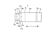
ここで、本実施の形態に係る半導体モジュール1が有するリードフレーム7の構成について、図2及び図3を参照して説明する。図2は、本実施の形態に係る半導体モジュール1が有するリードフレーム7の平面図である。図3は、本実施の形態に係るリードフレーム7の斜視図である。リードフレーム7は、全体に亘って同一の厚み寸法を有する金属板に対する曲げ加工(型加工)により成形される。
Here, the configuration of the
図2及び図3に示すように、リードフレーム7は、概して平面で構成される接合部71、72と、これらの接合部71、72を連結する連結部73とを含んで構成される。接合部71は、第1接合部の一例を構成し、接合部72は、第2接合部の一例を構成する。また、連結部73は、連結部の一例を構成する。接合部71と接合部72とは、左右方向に離間して配置されている。なお、接合部71、72および連結部73はそれぞれ実質的に平板形状であってよい。また、接合部71、72の角は、面取りされてもよい。
As shown in FIGS. 2 and 3, the
接合部71は、その一方側(図2に示す左方側)に配置された狭幅部71bと、その他方側(図2に示す右方側)に配置された広幅部71aとを有する。広幅部71aは、リードフレームを構成する金属板の幅方向(図2に示す上下方向)に第1の幅寸法Xを有する。狭幅部71bは、広幅部71aよりも狭い幅寸法Yを有し、広幅部71aの側縁部71cから左方側に突出して形成されている。
The
広幅部71a及び狭幅部71bは、平面視にて、いずれも概して長方形状を有している。例えば、広幅部71a及び狭幅部71bの左右方向の幅寸法は、同一に設定される。この場合、側縁部71cは、接合部71の左方側端部と右方側端部との中間位置に配置される。狭幅部71bは、平面視にて、広幅部71aの側縁部71cの中央部分(図2に示す上下方向の中央部分)に配置されている。接合部72は、図2に示す上下方向に同一幅の平坦面で構成される。接合部71の広幅部71a及び接合部72は、リードフレーム7を構成する金属板と同一の幅(幅寸法X)を有している。
The
連結部73は、接合部71、72よりも上方側の位置で左右方向に延在する連結面部73aと、連結面部73aの一方側(図2に示す左方側)の端部(一端部)から接合部71側(下方側)に向けて延びる脚部73bと、連結面部73aの他方側(図2に示す右方側)の端部(他端部)から接合部72側(下方側)延びる脚部73cとを有している。脚部73bは、第1脚部の一例を構成し、脚部73cは、第2脚部の一例を構成する。本実施の形態において、脚部73cは、脚部73bよりも上下方向に長い寸法を有している。このため、接合部71は、接合部72より上方側の位置で左右方向に延在している。
The connecting
脚部73bには、一対の連結脚部73b1、73b2が設けられている。これらの連結脚部73b1、73b2は、連結面部73aの側端部(図2に示す上方側端部、下方側端部)に配置されている。これらの連結脚部73b1、73b2は、接合部71における一方側(図2に示す左方側)の端部(より具体的には、狭幅部71bの左端部)と、接合部71における他方側(図2に示す右方側)の端部(より具体的には、広幅部71aの右端部)との間に配置される外縁部71dの一部に接続されている。ここで、接合部71における一方側の端部と他方側の端部との間に配置される外縁部71dとは、接合部71における左右の端部以外の外縁部(すなわち、図2に示す上方側及び下方側の外縁部)をいう。連結脚部73b1、73b2は、より具体的にいうと、狭幅部71bが突出する広幅部71aの側縁部71cの近傍であって、狭幅部71bの非形成領域に接続されている。更に具体的には、連結脚部73b1、73b2は、狭幅部71bの外側(図2に示す上方側及び下方向側)に配置された広幅部71aの一部に連結されている。一対の連結脚部73b1、73b2の間には、開口部74が形成されている。脚部73cは、平面部73aと同一幅の平面で構成される。The
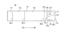
次に、上記構成を有するリードフレーム7の加工工程毎の状態について、図4~図6を参照して説明する。図4は、本実施の形態に係るリードフレーム7の加工前の展開図である。図5及び図6は、本実施の形態に係るリードフレーム7の加工過程の状態の斜視図である。図4~図6においては、図1に示した半導体モジュール1の上下方向及び左右方向を示している。図4及び図5Aに示すように、加工前のリードフレーム7を構成する金属板70は、平面視にて、左右方向に長手方向を有する実質的に長方形状を有している。
Next, the state of the
金属板70には、図4に示す右方側端部寄りの位置にスリットSAが形成されている。スリットSAは、金属板70の板面に垂直に金属板70を貫通して形成されている。スリットSAは、平面視にて、金属板70の端面と平行な方向(図4に示す上下方向)に延在する第1スリットS1と、第1スリットS1の両端部から図4に示す右方側に延びる一対の第2スリットS2とを有している。スリットSAは、平面視にて、全体として図4に示す右方側に開口したコ字形状を有している。第1スリットS1は、金属板70の図4に示す中央部分で延在している。第2スリットS2は、それぞれ金属板70の端面(図4に示す上下方向の端面)から僅かに内側の位置に形成され、互いに平行に延在している。金属板70およびスリットSAは、角に面取りが設けられてもよい。
A slit SA is formed in the
なお、図4~図6においては、説明の便宜上、金属板70に対して曲げ加工を行う位置に第1加工線BL1~第4加工線BL4を示している。第1加工線BL1は、第2スリットS2の右方側端部近傍で第2スリットS2の外側(図4に示す上方側及び下方側)に配置されている。第2加工線BL2は、第1スリットS1よりも僅かに左方側の位置に配置されている。第3加工線BL3は、金属板70の中央よりも僅かに左方側の位置に配置されている。第4加工線BL4は、金属板70の図4に示す左方側端部寄りの位置に配置されている。これらの第1加工線BL1~第4加工線BL4は、いずれも金属板70の左右方向の端面と平行に延在して設けられている。
In FIGS. 4 to 6, for convenience of explanation, the first processing line BL1 to the fourth processing line BL4 are shown at positions where the
また、図4及び図5Aにおいては、説明の便宜上、曲げ加工後のリードフレーム7の構成部分の符号を示している。図4及び図5Aに示すように、スリットSA及び第1加工線BL1よりも右方側の部分で接合部71が構成され、第2加工線BL2と第1加工線BL1及びスリットSAとの間の部分で連結部73の脚部73bが構成される。また、第2加工線BL2と第3加工線BL3との間の部分で連結部73の連結面部73aが構成され、第3加工線BL3と第4加工線BL4との間の部分で連結部73の脚部73cが構成され、第4加工線BL4よりも左方側の部分で接合部72が構成される。
Further, in FIGS. 4 and 5A, for convenience of explanation, the reference numerals of the constituent parts of the
リードフレーム7を加工する際には、まず、第1加工線BL1に沿って、金属板70のスリットSAより左方側部分を立ち上げるように曲げ加工が行われる。図5Bに示すように、金属板70は、非加工部分に対して垂直になる位置まで折り曲げられる。このように金属板70を折り曲げることにより接合部71、連結部73の脚部73b及び開口部74が形成される。
When processing the
このとき、スリットSAの内側に配置された金属板70の部分は、接合部71の狭幅部71bを構成する。第1加工線BL1より右方側の金属板70の部分は、接合部71の広幅部71aを構成する。また、第1加工線BL1に沿って配置される広幅部71aの一部は、狭幅部71bが突出形成される側縁部71cを構成する。接合部71に対する連結部73の脚部73bは、側縁部71c近傍であって、狭幅部71bが形成されていない領域(非形成領域)に曲げ加工により形成されている。
At this time, the portion of the
次に、第2加工線BL2に沿って、金属板70の第2加工線BL2より上方側部分を右方側に倒すように曲げ加工が行われる。図6Aに示すように、第2加工線BL2よりも上方側の金属板70の一部は、接合部71と平行になる位置まで折り曲げられる。このように金属板70を折り曲げることにより、連結部73の連結面部73aが形成される。
Next, bending is performed along the second processing line BL2 so that the portion of the
次に、第3加工線BL3に沿って、金属板70の第3加工線BL3より右方側部分を下方側に倒すように曲げ加工が行われる。図6Bに示すように、第3加工線BL3よりも右方側の金属板70の一部は、一対の脚部73bの延在方向と平行になる位置まで折り曲げられる。このように金属板70を折り曲げることにより、連結部73の脚部73cが形成される。
Next, bending is performed along the third processing line BL3 so that the portion on the right side of the third processing line BL3 of the
最後に、第4加工線BL4に沿って、金属板70の第4加工線BL4より下方側部分を上方側に起こすように曲げ加工が行われる。図3に示すように、第4加工線BL4よりも下方側の金属板70の一部は、接合部71と平行になる位置まで折り曲げられる。このように金属板70を折り曲げることにより、接合部72が形成される。このようにして、図3に示すリードフレーム7が完成する。
Finally, bending is performed along the fourth processing line BL4 so as to raise the lower portion of the
このように形成されたリードフレーム7が半導体チップ6及び電極パターン2bの上面にはんだ接合される。ここで、半導体チップ6に対するリードフレーム7の位置関係について、図7を参照して説明する。図7は、本実施の形態に係るリードフレーム7と半導体チップ6の位置関係の説明図である。図7A、図7Bにおいては、それぞれリードフレーム7の斜視図及び平面図を示している。また、図7においては、説明の便宜上、半導体チップ6の外縁部を一点鎖線で示している。
The
図7A、図7Bに示すように、本実施の形態において、リードフレーム7は、接合部71が半導体チップ6の中央領域に配置されるように、接合部71が半導体チップ6の上面にはんだ接合される。より具体的には、リードフレーム7は、一対の連結脚部73b1、73b2が、半導体チップ6における左方側端部61と右方側端部62との中間位置63を含む位置に配置されるように半導体チップ6に接合される(図7B参照)。As shown in FIGS. 7A and 7B, in the present embodiment, the
図7Aに示すように、リードフレーム7においては、接合部71における左方側端部と右方側端部との間に配置される外縁部71dの一部に連結部73の脚部73b(一対の連結脚部73b1、73b2)が接続される。このため、接合部71を半導体チップ6に接合するためのはんだに対する脚部73b(一対の連結脚部73b1、73b2)の接触面積を低減することができる。これにより、脚部73bを曲げ加工により形成する場合であっても、曲げ加工に伴って形成されるR形状部の表面積を縮小することができるので、はんだの這い上がり現象の発生を抑制し、半導体チップに対する応力集中を軽減することができる。As shown in FIG. 7A, in the
より具体的にいうと、リードフレーム7において、はんだの這い上がり現象の要因となるR形状部は、連結部73の脚部73b(一対の連結脚部73b1、73b2)の下端部(より具体的には、一対の連結脚部73b1、73b2の下端部における左方側面)のみに限定されている。これにより、接合部71の幅方向全体にR形状部を有する場合と比べてR形状部の表面積を大幅に縮小できるので、はんだの這い上がり現象の発生を抑制し、半導体チップ6に対する応力集中を軽減することができる。More specifically, in the
特に、本実施の形態に係るリードフレーム7において、連結部73の脚部73b(一対の連結脚部73b1、73b2)が、半導体チップ6における左方側端部61と右方側端部62との中間位置63を含む位置に配置されている。一般に、半導体チップ6は、外周縁部近傍の部分に対する応力集中により破損し易い。これに対し、本実施の形態に係るリードフレーム7によれば、脚部73b(一対の連結脚部73b1、73b2)が半導体チップ6の左右方向の中間位置63を含む位置に配置されることから、一対の連結脚部73b1、73b2周辺に応力が集中する場合であっても、半導体チップ6の中央近傍に応力集中箇所を配置できるので、半導体チップ6を破損し難くすることができる。In particular, in the
また、本実施の形態に係るリードフレーム7においては、連結面部73aの左方側端部から一対の連結脚部73b1、73b2が延び、接合部71における対向する外縁部71dに接続されている。これにより、一対の連結脚部73b1、73b2の周辺に応力が集中する場合であっても、当該応力集中箇所を離間した位置(図7Bに示す上下方向に離間した位置)に配置できるので、半導体チップ6に対する応力集中の影響を低減することができる。Further, in the
また、本実施の形態に係るリードフレーム7において、脚部73b(一対の連結脚部73b1、73b2)は、金属板70に形成されたスリットSAの周辺部分に曲げ加工を施すことで形成される(図5A及び図5B参照)。このため、複雑な構成を必要とすることなく、簡単に曲げ加工に伴って形成されるR形状部の表面積を縮小することができる。Further, in the
さらに、本実施の形態に係るリードフレーム7において、脚部73b(一対の連結脚部73b1、73b2)は、接合部71における左方側端部と右方側端部との間の中間位置(広幅部71aの側縁部71c)を含む位置に配置されている(図7B参照)。このため、リードフレーム7を接合する際の荷重を、脚部73bを介して接合部71の中央付近で受け止めることができるので、接合部71をバランス良く半導体チップ6に接合することができる。Further, in the
なお、本発明は上記実施の形態に限定されず、種々変更して実施することが可能である。上記実施の形態において、添付図面に図示されている構成要素の大きさや形状、機能などについては、これに限定されず、本発明の効果を発揮する範囲内で適宜変更することが可能である。その他、本発明の目的の範囲を逸脱しない限りにおいて適宜変更して実施することが可能である。 The present invention is not limited to the above embodiment, and can be modified in various ways. In the above embodiment, the size, shape, function, and the like of the components shown in the attached drawings are not limited to this, and can be appropriately changed within the range in which the effect of the present invention is exhibited. In addition, it can be appropriately modified and implemented as long as it does not deviate from the scope of the object of the present invention.
例えば、上記実施の形態においては、リードフレーム7を構成する金属板70にスリットSAを設け、一対の脚部73bを設ける場合について説明している。しかしながら、リードフレーム7の構成については、これに限定されるものではなく適宜変更が可能である。図8は、本実施の形態の変形例に係るリードフレーム7Aの斜視図(図8A)及び加工前の展開図(図8B)である。なお、図8において、上記実施の形態と共通の構成については、同一の符号を付与し、説明を省略する。
For example, in the above embodiment, a case where the slit SA is provided in the
図8Bに示すように、変形例に係るリードフレーム7Aにおいては、金属板70にスリットSBが形成される点でリードフレーム7と相違する。スリットSBは、金属板70の板面に垂直に金属板を貫通して形成されている。スリットSBは、平面視にて、金属板70の端面と平行(図8Bに示す上下方向)に延在する第3スリットS3と、図8Bに示す第3スリットS3の下端部から右方側に延在する第4スリットS4とを有している。第3スリットS3は、金属板70の図8Bに示す上端部から下方側に、金属板70の中央よりも僅かに下方側の位置まで延在している。第4スリットS4は、金属板70の長手方向に沿って延在している。
As shown in FIG. 8B, the
このように構成された金属板70に対し、上記実施の形態と同様の曲げ加工を施すことにより、図8Aに示すリードフレーム7Aが形成される。リードフレーム7Aにおいては、接合部71に接続される連結部73の脚部73bが単一の連結脚部73b3を有する点で、上記実施の形態に係るリードフレーム7と相違する。なお、連結脚部73b3は、連結脚部73b1又は連結脚部73b2に比べて幅が広く構成されている。連結脚部73b3は、一対の連結脚部73b1、73b2と同様に、接合部71における左方側端部と右方側端部との間に配置される外縁部71dの一部に接続されている。The
このような構成を有するリードフレーム7Aにおいても、はんだの這い上がり現象の要因となるR形状部は、連結部73の脚部73b(連結脚部73b3)の下端部のみに限定されている。これにより、接合部71の幅方向全体にR形状部を有する場合と比べてR形状部の表面積を大幅に縮小できるので、はんだの這い上がり現象の発生を抑制し、半導体チップ6に対する応力集中を軽減することができる。Even in the
また、上記実施の形態においては、リードフレーム7を構成する金属板70の板面に垂直にスリットSAを設ける場合について説明している。しかしながら、リードフレーム7の構成については、これに限定されるものではなく適宜変更が可能である。図9は、本実施の形態の変形例に係るリードフレーム7Bの斜視図(図9A)及び加工前の展開図(図9B)である。なお、図9において、上記実施の形態と共通の構成については、同一の符号を付与し、説明を省略する。
Further, in the above embodiment, a case where the slit SA is provided perpendicularly to the plate surface of the
図9Bに示すように、変形例に係るリードフレーム7Bにおいては、金属板70にスリットSCが形成される点でリードフレーム7と相違する。スリットSCは、第1スリットS1の両端から、金属板70の板面に垂直でなく、傾斜して形成される第5スリットS5を有する点でスリットSAと相違する。スリットSCの第5スリットS5は、図9Bに示す金属板70の上端部及び下端部に向けて切り込むように形成されている。
As shown in FIG. 9B, the
このように構成された金属板70に対し、上記実施の形態と同様の曲げ加工を施すことにより、図9Aに示すリードフレーム7Bが形成される。リードフレーム7Bにおいては、接合部71の狭幅部71bの側縁部に傾斜面部71eが形成される点で、上記実施の形態に係るリードフレーム7と相違する。傾斜面部71eは、狭幅部71bの外側に下方側に向かって幅方向の寸法が大きくなるように形成されている。傾斜面部71eは、一対の連結脚部73b1、73b2と、接合部71を接合するためのはんだとの接触を規制する規制部の一例を構成する。The
このような構成を有するリードフレーム7Bにおいては、狭幅部71bの外側に下方側に向かって幅方向の寸法が大きくなる傾斜面部71eが接合部71に形成されている。これにより、一対の連結脚部73b1、73b2における左方側面に対するはんだの接触が規制されることから、一対の連結脚部73b1、73b2における左方側面に対するはんだの這い上がり現象の発生を抑制できるので、半導体チップ6に対する応力集中を効果的に軽減することができる。In the
なお、ここでは、傾斜面部71eの下方側端部を広幅部71aの端面(図9Bに示す上下方向の端面)と同一位置に配置する場合について説明している。しかしながら、傾斜面部71eの下方側端部の位置については、これに限定されない。傾斜面部71eの下方側端部の位置は、狭幅部71bの上端部の位置よりも外側(図9Bに示す上下方向側)に配置されることを前提として任意の位置に配置することができる。
Here, a case where the lower end portion of the
下記に、上記の実施の形態における特徴点を整理する。
上記実施の形態に係るリードフレーム配線構造は、半導体素子と接続対象とを電気的に接続するリードフレーム配線構造であって、前記半導体素子にはんだ接合される第1接合部と、前記第1接合部から離間して配置され前記接続対象にはんだ接合される第2接合部と、前記第1接合部と前記第2接合部を連結する連結部と、を有し、前記連結部は、前記第1接合部及び前記第2接合部から上下方向に離間して配置される連結面部と、前記連結面部の一方側の端部から前記第1接合部側に延びる第1脚部と、前記連結面部の他方側の端部から前記第2接合部側に延びる第2脚部と、を有し、前記第1脚部は、前記第1接合部における前記一方側の端部と前記他方側の端部との間に配置された外縁部の一部に接続されることを特徴とする。この構成によれば、第1接合部における一方側の端部と他方側の端部との間に配置された外縁部の一部に第1脚部が接続される。このため、第1接合部を半導体素子に接合するためのはんだに対する第1脚部の接触面積を低減することができる。これにより、第1脚部を曲げ加工により形成する場合であっても、曲げ加工に伴って形成されるR形状部の表面積を縮小することができるので、はんだの這い上がり現象の発生を抑制し、半導体チップに対する応力集中を軽減することができる。The feature points in the above-described embodiment are summarized below.
The lead frame wiring structure according to the above embodiment is a lead frame wiring structure that electrically connects a semiconductor element and a connection target, and is a first joining portion soldered to the semiconductor element and the first joining. It has a second joint portion that is arranged apart from the portion and solder-bonded to the connection target, and a connecting portion that connects the first joint portion and the second joint portion, and the connecting portion is the first. A connecting surface portion arranged vertically separated from the first joint portion and the second joint portion, a first leg portion extending from one end of the connecting surface portion to the first joint portion side, and the connecting surface portion. It has a second leg portion extending from the other side end portion to the second joint portion side, and the first leg portion is the one side end portion and the other side end portion of the first joint portion. It is characterized in that it is connected to a part of an outer edge portion arranged between the portions. According to this configuration, the first leg portion is connected to a part of the outer edge portion arranged between the one-sided end portion and the other-side end portion in the first joint portion. Therefore, it is possible to reduce the contact area of the first leg portion with respect to the solder for joining the first joint portion to the semiconductor element. As a result, even when the first leg portion is formed by bending, the surface area of the R-shaped portion formed by bending can be reduced, so that the occurrence of the solder creep-up phenomenon is suppressed. , Stress concentration on the semiconductor chip can be reduced.
上記実施の形態に係るリードフレーム配線構造において、前記第1脚部は、前記第1接合部における前記一方側の端部と前記他方側の端部との中間位置を含む位置に配置される。この構成によれば、第1脚部が第1接合部における一方側の端部と他方側の端部との中間位置を含む位置に配置されることから、リードフレーム配線を接合する際の荷重を、第1脚部を介して第1接合部の中央付近で受け止めることができるので、第1接合部をバランス良く半導体素子に接合することができる。 In the lead frame wiring structure according to the above embodiment, the first leg portion is arranged at a position including an intermediate position between the one-sided end portion and the other-side end portion in the first joint portion. According to this configuration, since the first leg portion is arranged at the position including the intermediate position between the one-sided end portion and the other-side end portion in the first joint portion, the load when joining the lead frame wiring is performed. Can be received near the center of the first joint portion via the first leg portion, so that the first joint portion can be joined to the semiconductor element in a well-balanced manner.
上記実施の形態に係るリードフレーム配線構造において、前記第1脚部は、リードフレーム配線を構成する金属板に形成されたスリットの周辺部分に曲げ加工を施すことで形成される。この構成によれば、金属板に形成されたスリットの周辺部分に曲げ加工を施すことで第1脚部が形成されることから、複雑な構成を必要とすることなく、簡単に曲げ加工に伴って形成されるR形状部の表面積を縮小することができる。 In the lead frame wiring structure according to the above embodiment, the first leg portion is formed by bending a peripheral portion of a slit formed in a metal plate constituting the lead frame wiring. According to this configuration, the first leg portion is formed by bending the peripheral portion of the slit formed in the metal plate, so that the bending process can be easily performed without requiring a complicated structure. The surface area of the R-shaped portion formed in the above can be reduced.
上記実施の形態に係るリードフレーム配線構造において、前記第1接合部が前記半導体素子に接合された状態において、前記第1脚部は、前記半導体素子における前記一方側の端部と前記他方側の端部との中間位置を含む位置に配置される。この構成によれば、第1脚部が半導体素子における一方側の端部と他方側の端部との中間位置を含む位置に配置されることから、第1脚部の周辺に応力が集中する場合であっても、半導体素子の外周縁部近傍ではなく中央近傍に応力集中箇所を配置できるので、半導体素子を破損し難くすることができる。 In the lead frame wiring structure according to the above embodiment, in a state where the first joint portion is joined to the semiconductor element, the first leg portion is the end portion of the semiconductor element on one side and the other side thereof. It is placed at a position including an intermediate position with the end. According to this configuration, since the first leg portion is arranged at a position including an intermediate position between one end portion and the other side end portion of the semiconductor element, stress is concentrated around the first leg portion. Even in this case, since the stress concentration portion can be arranged not near the outer peripheral edge portion of the semiconductor element but near the center portion, it is possible to make the semiconductor element less likely to be damaged.
上記実施の形態に係るリードフレーム配線構造において、前記連結面部の前記一方側の端部から前記第1接合部側に一対の前記第1脚部が延び、前記第1接合部における対向する外縁部に接続される。この構成によれば、第1接合部における対向する外縁部に一対の第1脚部が接続されることから、第1脚部の周辺に応力集中が発生する場合であっても、当該応力集中箇所を離間した位置に配置できるので、半導体素子に対する応力集中の影響を低減することができる。 In the lead frame wiring structure according to the above embodiment, a pair of the first leg portions extend from the one-sided end portion of the connecting surface portion to the first joint portion side, and the opposite outer edge portions in the first joint portion. Connected to. According to this configuration, since the pair of first leg portions are connected to the opposite outer edge portions in the first joint portion, even when stress concentration occurs around the first leg portion, the stress concentration is concerned. Since the locations can be arranged at separate positions, the influence of stress concentration on the semiconductor element can be reduced.
上記実施の形態に係るリードフレーム配線構造において、前記第1接合部は、前記第1脚部における前記一方側の面に対するはんだの接触を規制する規制部を有する。この構成によれば、第1脚部における一方側の面に対するはんだの接触が規制されることから、第1脚部における一方側の面に対するはんだの這い上がり現象の発生を抑制できるので、半導体チップに対する応力集中を効果的に軽減することができる。 In the lead frame wiring structure according to the above embodiment, the first joint portion has a regulating portion that regulates contact of solder with the one side surface of the first leg portion. According to this configuration, since the contact of the solder with respect to one side surface of the first leg portion is restricted, the occurrence of the solder creeping phenomenon with respect to the one side surface of the first leg portion can be suppressed, so that the semiconductor chip can be suppressed. The stress concentration on the solder can be effectively reduced.
上記実施の形態に係る半導体モジュールは、上記したいずれかのリードフレーム配線構造を有することを特徴とする。この構成によれば、上述したリードフレーム配線構造で得られる効果を半導体モジュールで得ることができる。 The semiconductor module according to the above embodiment is characterized by having any of the above-mentioned lead frame wiring structures. According to this configuration, the effect obtained by the lead frame wiring structure described above can be obtained in the semiconductor module.
本発明の半導体モジュールは、半導体チップに対する応力集中を軽減することができるという効果を有し、車載用モータ駆動制御インバータなどの小型・軽量化や高温動作環境での長期信頼性が要求される半導体モジュールに好適である。 The semiconductor module of the present invention has the effect of reducing stress concentration on the semiconductor chip, and is required to be compact and lightweight, such as an in-vehicle motor drive control inverter, and to have long-term reliability in a high-temperature operating environment. Suitable for modules.
本出願は、2018年11月5日出願の特願2018-208087に基づく。この内容は、すべてここに含めておく。 This application is based on Japanese Patent Application No. 2018-208087 filed on November 5, 2018. All this content is included here.
Claims (7)
前記半導体素子にはんだ接合される第1接合部と、前記第1接合部から離間して配置され前記接続対象にはんだ接合される第2接合部と、前記第1接合部と前記第2接合部とを連結する連結部と、を有し、
前記連結部は、前記第1接合部及び前記第2接合部から上下方向に離間して配置される連結面部と、前記連結面部の前記一方側の端部から前記第1接合部側に延びる第1脚部と、前記連結面部の前記他方側の端部から前記第2接合部側に延びる第2脚部とを有し、
前記第1接合部は、広幅部と前記広幅部の側縁部から突出する狭幅部とを有し、
前記第1脚部は、前記第1接合部における前記一方側の端部と前記他方側の端部との間に配置される当該第1接合部の外縁部の一部であって前記広幅部における前記狭幅部の非形成領域に接続されることを特徴とするリードフレーム配線構造。It is a lead frame wiring structure that electrically connects a semiconductor element arranged on one side of the lead frame wiring and a connection target arranged on the other side of the lead frame wiring.
A first joint portion to be soldered to the semiconductor element, a second joint portion arranged apart from the first joint portion and soldered to the connection target, the first joint portion and the second joint portion. Has a connecting part that connects and
The connecting portion has a connecting surface portion arranged vertically separated from the first joint portion and the second joint portion, and a first joint portion extending from one end of the connecting surface portion to the first joint portion side. It has one leg and a second leg extending from the other end of the connecting surface to the second joint.
The first joint portion has a wide portion and a narrow portion protruding from the side edge portion of the wide portion.
The first leg portion is a part of the outer edge portion of the first joint portion arranged between the one-sided end portion and the other-side end portion of the first joint portion, and is the wide portion. The lead frame wiring structure, characterized in that it is connected to the non-formed region of the narrow portion in the above.
Applications Claiming Priority (3)
| Application Number | Priority Date | Filing Date | Title |
|---|---|---|---|
| JP2018208087 | 2018-11-05 | ||
| JP2018208087 | 2018-11-05 | ||
| PCT/JP2019/040010 WO2020095614A1 (en) | 2018-11-05 | 2019-10-10 | Lead frame wiring structure and semiconductor module |
Publications (2)
| Publication Number | Publication Date |
|---|---|
| JPWO2020095614A1 JPWO2020095614A1 (en) | 2021-04-30 |
| JP6992913B2 true JP6992913B2 (en) | 2022-01-13 |
Family
ID=70611944
Family Applications (1)
| Application Number | Title | Priority Date | Filing Date |
|---|---|---|---|
| JP2020556707A Active JP6992913B2 (en) | 2018-11-05 | 2019-10-10 | Lead frame wiring structure and semiconductor module |
Country Status (4)
| Country | Link |
|---|---|
| US (1) | US11302612B2 (en) |
| JP (1) | JP6992913B2 (en) |
| CN (1) | CN112119491A (en) |
| WO (1) | WO2020095614A1 (en) |
Families Citing this family (1)
| Publication number | Priority date | Publication date | Assignee | Title |
|---|---|---|---|---|
| DE112018003850B4 (en) * | 2017-07-28 | 2023-04-27 | Mitsubishi Electric Corporation | SEMICONDUCTOR UNIT AND SEMICONDUCTOR MODULE |
Citations (3)
| Publication number | Priority date | Publication date | Assignee | Title |
|---|---|---|---|---|
| JP2000124398A (en) | 1998-10-16 | 2000-04-28 | Mitsubishi Electric Corp | Power semiconductor module |
| JP2007173272A (en) | 2005-12-19 | 2007-07-05 | Mitsubishi Electric Corp | Semiconductor device and method of manufacturing same |
| JP2015207675A (en) | 2014-04-22 | 2015-11-19 | 三菱電機株式会社 | power semiconductor device |
Family Cites Families (15)
| Publication number | Priority date | Publication date | Assignee | Title |
|---|---|---|---|---|
| JPH01153648U (en) | 1988-04-04 | 1989-10-23 | ||
| JPH025558A (en) | 1988-06-24 | 1990-01-10 | Fuji Electric Co Ltd | Semiconductor device |
| JPH09116080A (en) | 1995-10-16 | 1997-05-02 | Nec Corp | Lead terminal and lead frame to be used for it |
| JP4098556B2 (en) * | 2001-07-31 | 2008-06-11 | ローム株式会社 | Terminal board, circuit board provided with the terminal board, and method for connecting the terminal board |
| JP2004200539A (en) * | 2002-12-20 | 2004-07-15 | Toshiba Corp | Component-connecting terminal and electronic device |
| JP4078993B2 (en) | 2003-01-27 | 2008-04-23 | 三菱電機株式会社 | Semiconductor device |
| US9184117B2 (en) * | 2010-06-18 | 2015-11-10 | Alpha And Omega Semiconductor Incorporated | Stacked dual-chip packaging structure and preparation method thereof |
| IT1402273B1 (en) * | 2010-07-29 | 2013-08-28 | St Microelectronics Srl | SEMICONDUCTOR ELEMENT WITH A SEMICONDUCTOR DIE AND CONNECTOR FRAMES |
| JP2012238684A (en) | 2011-05-11 | 2012-12-06 | Mitsubishi Electric Corp | Power semiconductor device |
| JP5823798B2 (en) * | 2011-09-29 | 2015-11-25 | ルネサスエレクトロニクス株式会社 | Semiconductor device |
| JP2015006017A (en) * | 2013-06-19 | 2015-01-08 | 富士電機株式会社 | Power conversion device |
| JP2015201505A (en) * | 2014-04-07 | 2015-11-12 | 三菱電機株式会社 | semiconductor device |
| WO2016084483A1 (en) * | 2014-11-27 | 2016-06-02 | 新電元工業株式会社 | Lead frame, semiconductor device, method for manufacturing lead frame, and method for manufacturing semiconductor device |
| US9496208B1 (en) * | 2016-02-25 | 2016-11-15 | Texas Instruments Incorporated | Semiconductor device having compliant and crack-arresting interconnect structure |
| JP6870249B2 (en) | 2016-09-14 | 2021-05-12 | 富士電機株式会社 | Semiconductor devices and methods for manufacturing semiconductor devices |
-
2019
- 2019-10-10 WO PCT/JP2019/040010 patent/WO2020095614A1/en active Application Filing
- 2019-10-10 CN CN201980029764.4A patent/CN112119491A/en active Pending
- 2019-10-10 JP JP2020556707A patent/JP6992913B2/en active Active
-
2020
- 2020-10-30 US US17/085,758 patent/US11302612B2/en active Active
Patent Citations (3)
| Publication number | Priority date | Publication date | Assignee | Title |
|---|---|---|---|---|
| JP2000124398A (en) | 1998-10-16 | 2000-04-28 | Mitsubishi Electric Corp | Power semiconductor module |
| JP2007173272A (en) | 2005-12-19 | 2007-07-05 | Mitsubishi Electric Corp | Semiconductor device and method of manufacturing same |
| JP2015207675A (en) | 2014-04-22 | 2015-11-19 | 三菱電機株式会社 | power semiconductor device |
Also Published As
| Publication number | Publication date |
|---|---|
| US20210050286A1 (en) | 2021-02-18 |
| JPWO2020095614A1 (en) | 2021-04-30 |
| WO2020095614A1 (en) | 2020-05-14 |
| CN112119491A (en) | 2020-12-22 |
| US11302612B2 (en) | 2022-04-12 |
Similar Documents
| Publication | Publication Date | Title |
|---|---|---|
| US8258622B2 (en) | Power device package and semiconductor package mold for fabricating the same | |
| JP5558714B2 (en) | Semiconductor package | |
| CN109314063B (en) | Power semiconductor device | |
| JP4989552B2 (en) | Electronic components | |
| JP4803241B2 (en) | Semiconductor module | |
| JP2013069782A (en) | Semiconductor device | |
| JP7237647B2 (en) | Circuit boards and electronic devices | |
| JP5217015B2 (en) | Power converter and manufacturing method thereof | |
| US11735557B2 (en) | Power module of double-faced cooling | |
| JP6992913B2 (en) | Lead frame wiring structure and semiconductor module | |
| US8921989B2 (en) | Power electronics modules with solder layers having reduced thermal stress | |
| JP6870249B2 (en) | Semiconductor devices and methods for manufacturing semiconductor devices | |
| JP2019083292A (en) | Semiconductor device | |
| JP5840102B2 (en) | Power semiconductor device | |
| JP2005150596A (en) | Semiconductor device and its manufacturing method | |
| JP7396118B2 (en) | semiconductor module | |
| JP7147186B2 (en) | semiconductor equipment | |
| JP2021019063A (en) | Semiconductor device | |
| US20200266130A1 (en) | Semiconductor device | |
| JP7543655B2 (en) | Semiconductor Module | |
| JP7524559B2 (en) | Wiring structure and semiconductor module | |
| WO2023203688A1 (en) | Semiconductor device and production method for semiconductor device | |
| US20220122899A1 (en) | Semiconductor apparatus and vehicle | |
| JP7106891B2 (en) | semiconductor equipment | |
| KR20220063570A (en) | Semisonductor element package |
Legal Events
| Date | Code | Title | Description |
|---|---|---|---|
| A524 | Written submission of copy of amendment under article 19 pct |
Free format text: JAPANESE INTERMEDIATE CODE: A527 Effective date: 20201026 |
|
| A621 | Written request for application examination |
Free format text: JAPANESE INTERMEDIATE CODE: A621 Effective date: 20201026 |
|
| TRDD | Decision of grant or rejection written | ||
| A01 | Written decision to grant a patent or to grant a registration (utility model) |
Free format text: JAPANESE INTERMEDIATE CODE: A01 Effective date: 20211109 |
|
| A61 | First payment of annual fees (during grant procedure) |
Free format text: JAPANESE INTERMEDIATE CODE: A61 Effective date: 20211122 |
|
| R150 | Certificate of patent or registration of utility model |
Ref document number: 6992913 Country of ref document: JP Free format text: JAPANESE INTERMEDIATE CODE: R150 |