JP6983602B2 - Board processing equipment and board processing method - Google Patents

Board processing equipment and board processing method Download PDF

Info

Publication number
JP6983602B2
JP6983602B2 JP2017185312A JP2017185312A JP6983602B2 JP 6983602 B2 JP6983602 B2 JP 6983602B2 JP 2017185312 A JP2017185312 A JP 2017185312A JP 2017185312 A JP2017185312 A JP 2017185312A JP 6983602 B2 JP6983602 B2 JP 6983602B2
Authority
JP
Japan
Prior art keywords
cup body
substrate
treatment liquid
liquid
rotating
Prior art date
Legal status (The legal status is an assumption and is not a legal conclusion. Google has not performed a legal analysis and makes no representation as to the accuracy of the status listed.)
Active
Application number
JP2017185312A
Other languages
Japanese (ja)
Other versions
JP2019062075A (en
JP2019062075A5 (en
Inventor
正明 古矢
克弘 山崎
秀樹 森
航之介 林
Current Assignee (The listed assignees may be inaccurate. Google has not performed a legal analysis and makes no representation or warranty as to the accuracy of the list.)
Shibaura Mechatronics Corp
Original Assignee
Shibaura Mechatronics Corp
Priority date (The priority date is an assumption and is not a legal conclusion. Google has not performed a legal analysis and makes no representation as to the accuracy of the date listed.)
Filing date
Publication date
Application filed by Shibaura Mechatronics Corp filed Critical Shibaura Mechatronics Corp
Priority to JP2017185312A priority Critical patent/JP6983602B2/en
Priority to TW107131482A priority patent/TWI687266B/en
Priority to KR1020180113166A priority patent/KR102221337B1/en
Priority to CN201811120882.XA priority patent/CN109560018B/en
Publication of JP2019062075A publication Critical patent/JP2019062075A/en
Publication of JP2019062075A5 publication Critical patent/JP2019062075A5/ja
Application granted granted Critical
Publication of JP6983602B2 publication Critical patent/JP6983602B2/en
Active legal-status Critical Current
Anticipated expiration legal-status Critical

Links

Images

Classifications

    • HELECTRICITY
    • H01ELECTRIC ELEMENTS
    • H01LSEMICONDUCTOR DEVICES NOT COVERED BY CLASS H10
    • H01L21/00Processes or apparatus adapted for the manufacture or treatment of semiconductor or solid state devices or of parts thereof
    • H01L21/67Apparatus specially adapted for handling semiconductor or electric solid state devices during manufacture or treatment thereof; Apparatus specially adapted for handling wafers during manufacture or treatment of semiconductor or electric solid state devices or components ; Apparatus not specifically provided for elsewhere
    • H01L21/67005Apparatus not specifically provided for elsewhere
    • H01L21/67011Apparatus for manufacture or treatment
    • H01L21/67017Apparatus for fluid treatment
    • H01L21/67028Apparatus for fluid treatment for cleaning followed by drying, rinsing, stripping, blasting or the like
    • H01L21/6704Apparatus for fluid treatment for cleaning followed by drying, rinsing, stripping, blasting or the like for wet cleaning or washing
    • HELECTRICITY
    • H01ELECTRIC ELEMENTS
    • H01LSEMICONDUCTOR DEVICES NOT COVERED BY CLASS H10
    • H01L21/00Processes or apparatus adapted for the manufacture or treatment of semiconductor or solid state devices or of parts thereof
    • H01L21/67Apparatus specially adapted for handling semiconductor or electric solid state devices during manufacture or treatment thereof; Apparatus specially adapted for handling wafers during manufacture or treatment of semiconductor or electric solid state devices or components ; Apparatus not specifically provided for elsewhere
    • H01L21/67005Apparatus not specifically provided for elsewhere
    • H01L21/67011Apparatus for manufacture or treatment
    • H01L21/67017Apparatus for fluid treatment
    • HELECTRICITY
    • H01ELECTRIC ELEMENTS
    • H01LSEMICONDUCTOR DEVICES NOT COVERED BY CLASS H10
    • H01L21/00Processes or apparatus adapted for the manufacture or treatment of semiconductor or solid state devices or of parts thereof
    • H01L21/02Manufacture or treatment of semiconductor devices or of parts thereof
    • H01L21/02041Cleaning
    • H01L21/02043Cleaning before device manufacture, i.e. Begin-Of-Line process
    • H01L21/02052Wet cleaning only
    • HELECTRICITY
    • H01ELECTRIC ELEMENTS
    • H01LSEMICONDUCTOR DEVICES NOT COVERED BY CLASS H10
    • H01L21/00Processes or apparatus adapted for the manufacture or treatment of semiconductor or solid state devices or of parts thereof
    • H01L21/02Manufacture or treatment of semiconductor devices or of parts thereof
    • H01L21/02041Cleaning
    • H01L21/02057Cleaning during device manufacture
    • HELECTRICITY
    • H01ELECTRIC ELEMENTS
    • H01LSEMICONDUCTOR DEVICES NOT COVERED BY CLASS H10
    • H01L21/00Processes or apparatus adapted for the manufacture or treatment of semiconductor or solid state devices or of parts thereof
    • H01L21/67Apparatus specially adapted for handling semiconductor or electric solid state devices during manufacture or treatment thereof; Apparatus specially adapted for handling wafers during manufacture or treatment of semiconductor or electric solid state devices or components ; Apparatus not specifically provided for elsewhere
    • H01L21/67005Apparatus not specifically provided for elsewhere
    • H01L21/67011Apparatus for manufacture or treatment
    • H01L21/67017Apparatus for fluid treatment
    • H01L21/67023Apparatus for fluid treatment for general liquid treatment, e.g. etching followed by cleaning
    • HELECTRICITY
    • H01ELECTRIC ELEMENTS
    • H01LSEMICONDUCTOR DEVICES NOT COVERED BY CLASS H10
    • H01L21/00Processes or apparatus adapted for the manufacture or treatment of semiconductor or solid state devices or of parts thereof
    • H01L21/67Apparatus specially adapted for handling semiconductor or electric solid state devices during manufacture or treatment thereof; Apparatus specially adapted for handling wafers during manufacture or treatment of semiconductor or electric solid state devices or components ; Apparatus not specifically provided for elsewhere
    • H01L21/67005Apparatus not specifically provided for elsewhere
    • H01L21/67011Apparatus for manufacture or treatment
    • H01L21/67017Apparatus for fluid treatment
    • H01L21/67028Apparatus for fluid treatment for cleaning followed by drying, rinsing, stripping, blasting or the like
    • HELECTRICITY
    • H01ELECTRIC ELEMENTS
    • H01LSEMICONDUCTOR DEVICES NOT COVERED BY CLASS H10
    • H01L21/00Processes or apparatus adapted for the manufacture or treatment of semiconductor or solid state devices or of parts thereof
    • H01L21/67Apparatus specially adapted for handling semiconductor or electric solid state devices during manufacture or treatment thereof; Apparatus specially adapted for handling wafers during manufacture or treatment of semiconductor or electric solid state devices or components ; Apparatus not specifically provided for elsewhere
    • H01L21/67005Apparatus not specifically provided for elsewhere
    • H01L21/67011Apparatus for manufacture or treatment
    • H01L21/6715Apparatus for applying a liquid, a resin, an ink or the like
    • HELECTRICITY
    • H01ELECTRIC ELEMENTS
    • H01LSEMICONDUCTOR DEVICES NOT COVERED BY CLASS H10
    • H01L21/00Processes or apparatus adapted for the manufacture or treatment of semiconductor or solid state devices or of parts thereof
    • H01L21/67Apparatus specially adapted for handling semiconductor or electric solid state devices during manufacture or treatment thereof; Apparatus specially adapted for handling wafers during manufacture or treatment of semiconductor or electric solid state devices or components ; Apparatus not specifically provided for elsewhere
    • H01L21/683Apparatus specially adapted for handling semiconductor or electric solid state devices during manufacture or treatment thereof; Apparatus specially adapted for handling wafers during manufacture or treatment of semiconductor or electric solid state devices or components ; Apparatus not specifically provided for elsewhere for supporting or gripping
    • H01L21/687Apparatus specially adapted for handling semiconductor or electric solid state devices during manufacture or treatment thereof; Apparatus specially adapted for handling wafers during manufacture or treatment of semiconductor or electric solid state devices or components ; Apparatus not specifically provided for elsewhere for supporting or gripping using mechanical means, e.g. chucks, clamps or pinches
    • H01L21/68714Apparatus specially adapted for handling semiconductor or electric solid state devices during manufacture or treatment thereof; Apparatus specially adapted for handling wafers during manufacture or treatment of semiconductor or electric solid state devices or components ; Apparatus not specifically provided for elsewhere for supporting or gripping using mechanical means, e.g. chucks, clamps or pinches the wafers being placed on a susceptor, stage or support
    • H01L21/68764Apparatus specially adapted for handling semiconductor or electric solid state devices during manufacture or treatment thereof; Apparatus specially adapted for handling wafers during manufacture or treatment of semiconductor or electric solid state devices or components ; Apparatus not specifically provided for elsewhere for supporting or gripping using mechanical means, e.g. chucks, clamps or pinches the wafers being placed on a susceptor, stage or support characterised by a movable susceptor, stage or support, others than those only rotating on their own vertical axis, e.g. susceptors on a rotating caroussel

Description

本発明は、回転する基板に処理液を供給して基板処理を行う、基板処理装置及び基板処理方法に関する。 The present invention relates to a substrate processing apparatus and a substrate processing method in which a processing liquid is supplied to a rotating substrate to perform substrate processing.

半導体ウェーハやフォトマスク用ガラス基板の表面処理装置としては、表面処理の均一性、再現性の向上の点から、基板を1枚ずつ処理する枚葉方式を採用する傾向がある。枚葉方式の基板処理装置では、水平に保持した基板をその中心軸周りに回転(スピン)させながら、例えば薬液などの処理液を基板の表面の中央に供給する。基板に供給された処理液は、遠心力で基板の表面の全面に広がる。これにより、基板全体の処理が行われる。所定の薬液処理が終了すると、基板表面に残った薬液をリンス液で洗い流すためのリンス処理が行われる。リンス処理は、上記同様に回転する基板に対して行われ、リンス処理の終了後には、基板を高速に回転させて、基板の乾燥処理が行われる。 As a surface treatment device for a glass substrate for a semiconductor wafer or a photomask, there is a tendency to adopt a single-wafer method in which the substrates are treated one by one from the viewpoint of improving the uniformity and reproducibility of the surface treatment. In the single-wafer type substrate processing apparatus, a processing liquid such as a chemical solution is supplied to the center of the surface of the substrate while rotating (spinning) the horizontally held substrate around its central axis. The treatment liquid supplied to the substrate spreads over the entire surface of the substrate by centrifugal force. As a result, the entire substrate is processed. When the predetermined chemical solution treatment is completed, a rinsing treatment is performed to wash away the chemical solution remaining on the surface of the substrate with the rinsing solution. The rinsing treatment is performed on the rotating substrate in the same manner as described above, and after the rinsing treatment is completed, the substrate is rotated at high speed to dry the substrate.

上記した枚葉方式の基板処理装置では、回転する基板上の処理液(薬液やリンス液など)は、基板端(基板の外周縁)又は基板を保持する回転体の回転体端から遠心力により基板外に飛散する。飛散した処理液は、処理槽内の所定領域に集められて廃液されるか、又は再利用のために回収される(例えば、特許文献1参照)。 In the single-wafer type substrate processing apparatus described above, the processing liquid (chemical solution, rinsing liquid, etc.) on the rotating substrate is centrifugally applied from the edge of the substrate (outer peripheral edge of the substrate) or the end of the rotating body holding the substrate. Scatter outside the board. The scattered treatment liquid is collected in a predetermined area in the treatment tank and discharged, or is recovered for reuse (see, for example, Patent Document 1).

実用新案登録第2533339号公報Utility Model Registration No. 2533339

特許文献1に記載の基板の回転処理装置では、スピンチャックの周囲を覆うように設けられた内容器の底部に排液口が形成され、その排液口に対向する位置に、回転可能に桶部材が設置され、この桶部材を回転させて、桶部材の下部にある1つの排液流出口を外容器に設けた複数のドレン口(回収路)の1つに選択的に対向させることで、複数種の処理液の分離回収を可能としている。 In the substrate rotation processing device described in Patent Document 1, a drainage port is formed at the bottom of an inner container provided so as to cover the periphery of the spin chuck, and a rotatable tub is formed at a position facing the drainage port. A member is installed, and the tub member is rotated so that one drainage outlet at the bottom of the tub member is selectively opposed to one of a plurality of drain ports (collection paths) provided in the outer container. , It is possible to separate and recover multiple types of treatment liquids.

しかしながら、特許文献1に記載の基板の回転処理装置では、処理液の切り替えに伴い、桶部材を回転させて、排液流出口を所定のドレン口と対向する位置に位置付ける際、排液流出口が、別のドレン口の上方を通過することがある。桶部材には今まで使用していた処理液が残留しているから、この残留液が、本来のドレン口以外に浸入してしまう危険性を有している。処理液が混入すると、分離回収による処理液の再利用に支障が生じてしまう。 However, in the substrate rotation processing apparatus described in Patent Document 1, when the tub member is rotated to position the drainage outlet at a position facing a predetermined drain port as the treatment liquid is switched, the drainage outlet is discharged. However, it may pass above another drainage port. Since the treatment liquid used up to now remains in the tub member, there is a risk that this residual liquid will infiltrate into other than the original drain port. If the treatment liquid is mixed in, it will hinder the reuse of the treatment liquid by separation and recovery.

本発明は、複数種の処理液の分離回収を効率的に行うことができる基板処理装置及び基板処理方法の提供を目的とする。 An object of the present invention is to provide a substrate processing apparatus and a substrate processing method capable of efficiently separating and recovering a plurality of types of processing liquids.

上記課題を解決するために、本発明に係る基板処理装置は、基板に複数種の処理液を順次供給して基板を処理する基板処理装置において、前記基板を保持して回転する基板回転手段と、前記基板回転手段により回転する前記基板に処理液を供給する処理液供給手段と、前記基板の周囲に設けられ、前記基板から飛散する前記処理液を受け入れるカップ体と、前記カップ体が受け入れた処理液の種類に応じて、前記カップ体から前記処理液を流す各種の回収路と、前記カップ体を水平回動させて、前記カップ体と前記処理液の種類に応じた回収路が位置する方向に切り替える回動手段と、前記カップ体を上下方向に昇降させて、前記回動手段による前記カップ体と前記処理液の種類に応じた回収路と連通する第1の高さ位置と、前記カップ体が受け入れた前記処理液を廃液路に流す第2の高さ位置とに切り替える昇降手段と、を有する構成である。 In order to solve the above problems, the substrate processing apparatus according to the present invention is a substrate processing apparatus that sequentially supplies a plurality of types of processing liquids to the substrate to process the substrate, and is a substrate rotating means for holding and rotating the substrate. , The processing liquid supply means for supplying the processing liquid to the substrate rotated by the substrate rotating means, the cup body provided around the substrate and receiving the processing liquid scattered from the substrate, and the cup body received. Depending on the type of the treatment liquid, various recovery paths for flowing the treatment liquid from the cup body and recovery paths corresponding to the types of the cup body and the treatment liquid by rotating the cup body horizontally are located. The rotating means for switching in the direction, the first height position where the cup body is moved up and down in the vertical direction to communicate with the cup body by the rotating means and the collection path according to the type of the processing liquid, and the above. The structure includes an elevating means for switching to a second height position at which the treatment liquid received by the cup body flows into the waste liquid passage.

また、本発明に係る基板処理方法は、基板に複数種の処理液を順次供給して基板を処理する基板処理方法であって、前記基板を基板回転手段により回転させるステップと、前記基板回転手段により回転する前記基板に前記処理液を供給するステップと、前記基板から飛散する前記処理液をカップ体によって受けるステップと、前記カップ体を水平回動させて、前記カップ体と前記処理液の種類に応じた回収路が位置する方向に切り替えるステップと、
前記カップ体を上下方向に昇降させて、前記カップ体と前記処理液の種類に応じた回収路が連通する第1の高さに移動させるステップと、前記カップ体が受け入れた前記処理液を廃液路に流す第2の高さ位置に移動させるステップと、を有する構成である。
Further, the substrate processing method according to the present invention is a substrate processing method in which a plurality of types of processing liquids are sequentially supplied to a substrate to process the substrate, and the step of rotating the substrate by the substrate rotating means and the substrate rotating means. The step of supplying the treatment liquid to the substrate rotated by the substrate, the step of receiving the treatment liquid scattered from the substrate by the cup body, and the type of the cup body and the treatment liquid by horizontally rotating the cup body. Steps to switch to the direction in which the collection path is located according to
The step of moving the cup body up and down to a first height at which the cup body and the collection path according to the type of the treatment liquid communicate with each other, and the waste liquid of the treatment liquid received by the cup body. It is configured to have a step of moving to a second height position to flow in the road.

本発明によれば、複数種の処理液の分離回収を効率的に行うことができる。 According to the present invention, it is possible to efficiently separate and recover a plurality of types of treatment liquids.

本発明の第1の実施形態に係る基板処理装置の縦断面図である(カップ体が上昇した高位置(第1の高さ位置))。It is a vertical sectional view of the substrate processing apparatus which concerns on 1st Embodiment of this invention (high position where a cup body was raised (first height position)). 本発明の第1の実施形態に係る基板処理装置の縦断面図である(カップ体が下降した低位置(第2の高さ位置))。It is a vertical sectional view of the substrate processing apparatus which concerns on 1st Embodiment of this invention (a low position where a cup body lowered (second height position)). 図1のA−A断面図である。FIG. 1 is a cross-sectional view taken along the line AA of FIG. 図2のB−B断面図である。FIG. 2 is a cross-sectional view taken along the line BB of FIG. カップ体を上昇させた高位置(第1の高さ位置)における流出孔部から回収配管への処理液の流出を示す一部断面図である(その1)。It is a partial sectional view showing the outflow of the processing liquid from the outflow hole portion to the recovery pipe at the high position (first height position) in which the cup body is raised (No. 1). カップ体を上昇させた高位置(第1の高さ位置)における流出孔部から回収配管への処理液の流出を示す一部断面図である(その2)。It is a partial sectional view showing the outflow of the processing liquid from the outflow hole portion to the recovery pipe at the high position (first height position) in which the cup body is raised (No. 2). カップ体を上昇させた高位置(第1の高さ位置)における流出孔部から回収配管への処理液の流出を示す一部断面図である(その3)。It is a partial sectional view showing the outflow of the processing liquid from the outflow hole portion to the recovery pipe at the high position (first height position) in which the cup body is raised (No. 3). カップ体の排気隙間から排気配管への処理液を含む排気の流出を示す一部断面図である(その1)。It is a partial sectional view showing the outflow of the exhaust gas containing the processing liquid from the exhaust gap of the cup body to the exhaust pipe (No. 1). カップ体の排気隙間から排気配管への処理液を含む排気の流出を示す一部断面図である(その2)。It is a partial sectional view showing the outflow of the exhaust gas containing the processing liquid from the exhaust gap of the cup body to the exhaust pipe (No. 2). カップ体の排気隙間から排気配管への処理液を含む排気の流出を示す一部断面図である(その3)。It is a partial sectional view showing the outflow of the exhaust gas containing the processing liquid from the exhaust gap of the cup body to the exhaust pipe (No. 3). カップ体を下降させた低位置(第2の高さ位置)における流出孔部から廃液経路61への処理液の流出を示す一部断面図である(その1)。It is a partial cross-sectional view which shows the outflow of the processing liquid from the outflow hole portion to the waste liquid passage 61 in the low position (second height position) which lowered the cup body (the 1). カップ体を下降させた低位置(第2の高さ位置)における流出孔部から廃液経路61への処理液の流出を示す一部断面図である(その2)。It is a partial cross-sectional view which shows the outflow of the processing liquid from the outflow hole portion to the waste liquid passage 61 in the low position (second height position) which lowered the cup body (the 2). カップ体を下降させた低位置(第2の高さ位置)における流出孔部から廃液経路61への処理液の流出を示す一部断面図である(その3)。FIG. 3 is a partial cross-sectional view showing the outflow of the treated liquid from the outflow hole portion to the waste liquid path 61 at a low position (second height position) in which the cup body is lowered (No. 3). 図1のC−C断面図である。FIG. 3 is a sectional view taken along the line CC of FIG. 本発明の第1実施形態に係る基板処理装置における回収配管の一部斜視図である。It is a partial perspective view of the recovery pipe in the substrate processing apparatus which concerns on 1st Embodiment of this invention. 本発明の第1実施形態に係る基板処理装置における排気配管の一部斜視図である。It is a partial perspective view of the exhaust pipe in the substrate processing apparatus which concerns on 1st Embodiment of this invention. 本発明の第2実施形態に係る基板処理装置の横断面図である。It is a cross-sectional view of the substrate processing apparatus which concerns on 2nd Embodiment of this invention. カップ体の変形例1を示す縦断面図である。It is a vertical sectional view which shows the modification 1 of a cup body. カップ体の変形例2を示す縦断面図である。It is a vertical sectional view which shows the modification 2 of a cup body.

(第1の実施形態)
以下、本発明の第1の実施形態について図面を用いて説明する。
(First Embodiment)
Hereinafter, the first embodiment of the present invention will be described with reference to the drawings.

本発明の第1の実施形態に係る基板処理装置の基本的な構造が、図1〜図4に示される。 The basic structure of the substrate processing apparatus according to the first embodiment of the present invention is shown in FIGS. 1 to 4.

本実施形態に係る基板処理装置の縦断面図である図1において、基板処理装置11は、外部装置である搬送ロボット(不図示)により搬送された半導体ウェーハなどの基板12を回転させるための円板形状の回転体13と、回転体13を覆うようにその上部に設けられた円板形状のカバー部15を有する。カバー部15の外周側表面内での周方向には、60度間隔で所定位置に6個の回転板17(図1では2個のみ図示)が配置される。各回転板17の上面には、回転板17の中心軸Tから偏心した位置に、回転体13に載置された基板12を保持及び開放するクランプピン18(図1では4個のみ図示)が設けられる。基板12の上方には、基板12の表面(上面)に処理液(例えば、エッチング液、リンス液等)を供給するノズル20(20a、20b、20c、20d)が配置される。回転体13には、回転軸である円筒部材の動力伝動体21が一体に設けられ、その動力伝達体21は、駆動モータ22によって回転駆動される。 In FIG. 1, which is a vertical sectional view of the substrate processing apparatus according to the present embodiment, the substrate processing apparatus 11 is a circle for rotating a substrate 12 such as a semiconductor wafer conveyed by a transfer robot (not shown) which is an external device. It has a plate-shaped rotating body 13 and a disk-shaped cover portion 15 provided on the upper portion of the rotating body 13 so as to cover the rotating body 13. Six rotating plates 17 (only two are shown in FIG. 1) are arranged at predetermined positions at intervals of 60 degrees in the circumferential direction of the cover portion 15 on the outer peripheral side surface. On the upper surface of each rotating plate 17, clamp pins 18 (only four are shown in FIG. 1) that hold and release the substrate 12 mounted on the rotating body 13 at a position eccentric from the central axis T of the rotating plate 17. It will be provided. Above the substrate 12, nozzles 20 (20a, 20b, 20c, 20d) for supplying a treatment liquid (for example, an etching liquid, a rinsing liquid, etc.) to the surface (upper surface) of the substrate 12 are arranged. The rotating body 13 is integrally provided with a power transmission body 21 of a cylindrical member which is a rotation axis, and the power transmission body 21 is rotationally driven by a drive motor 22.

駆動モータ22は、回転子2aと固定子2bを有して構成される。回転子26aは、下部のベース板23に形成された円形の通孔25を貫通して設けられ、固定子2bは、ベース板23の下で回転子2aの周囲に設けられる。円筒部材である回転子2aの上端が、円筒部材である動力伝動体21と一体となるように接続される。これにより、駆動モータ22の回転子2aが動力伝動体21を通じて回転体13を回転させることで、クランプピン18により保持された基板12を回転させる構造となっている。なお、駆動モータ22は、制御部100に電気的に接続され、その駆動を制御部100に記憶された基板処理情報や各種プログラムに基づいて制御される。 The drive motor 22 includes a rotor 2 6 a and a stator 2 6 b. The rotor 26a is provided through the circular hole 25 formed in the lower portion of the base plate 23, the stator 2 6 b is provided around the rotor 2 6 a under the base plate 23. The upper end of the rotor 2 6 a is a cylindrical member is connected so as to be integral with the power transmission member 21 is a cylindrical member. Thus, the rotor 2 6 a of the driving motor 22 rotates rotation member 13 through the power transmission member 21 has a structure which rotates the substrate 12 held by the clamp pin 18. The drive motor 22 is electrically connected to the control unit 100, and its drive is controlled based on the substrate processing information stored in the control unit 100 and various programs.

回転子2a及び動力伝動体21の中空内部には、非回転の保持筒27が、回転子2a及び動力伝動体21と同軸に設けられる。この保持筒27の上端部には、円錐形状の凹部を有するノズルヘッド28が取り付けられ、このノズルヘッド28に、基板12の裏面に処理液等を噴射する複数のノズル29が設けられる。各ノズル29は、処理液供給部(不図示)に接続されている。各ノズル29から噴射された処理液等を排出するために、保持筒27内には中空の管体31が設けられ、その一端はノズルヘッド28を貫通して、ノズルヘッド28に形成される凹部の底部に接続され、他端は廃液タンク等(不図示)に接続される。また、カバー部15の中央には、ノズル29から基板12の裏面に向けて噴射される処理液を通過させるための開口部15aが形成されている。ノズル20とノズル29は、処理液供給手段を構成する。なお、ノズル29は、基板12の裏面(図1では下面)を処理するために設けられているが、基板12の表面(図1では上面)のみを処理する場合には、なくてもよい。なお、ノズル20及びノズル29からの処理液の供給は、制御部100に記憶された基板処理情報や各種プログラムに基づいて制御される。 The hollow interior of the rotor 2 6 a and the power transmission member 21, the holding cylinder 27 of the non-rotating is provided coaxially with the rotor 2 6 a and power transmission member 21. A nozzle head 28 having a conical recess is attached to the upper end of the holding cylinder 27, and the nozzle head 28 is provided with a plurality of nozzles 29 for injecting a treatment liquid or the like on the back surface of the substrate 12. Each nozzle 29 is connected to a processing liquid supply unit (not shown). A hollow tube 31 is provided in the holding cylinder 27 in order to discharge the treatment liquid or the like ejected from each nozzle 29, and one end thereof penetrates the nozzle head 28 and is formed in the nozzle head 28. The other end is connected to a waste liquid tank or the like (not shown). Further, in the center of the cover portion 15, an opening portion 15a for passing the processing liquid jetted from the nozzle 29 toward the back surface of the substrate 12 is formed. The nozzle 20 and the nozzle 29 form a processing liquid supply means. The nozzle 29 is provided for processing the back surface of the substrate 12 (lower surface in FIG. 1), but may not be provided when processing only the front surface of the substrate 12 (upper surface in FIG. 1). The supply of the processing liquid from the nozzle 20 and the nozzle 29 is controlled based on the substrate processing information stored in the control unit 100 and various programs.

各クランプピン18が支持される回転板17の下面には、ピン回転体35が、そしてピン回転体35の下端には、子歯車36が、同軸(T)に結合されている(図1には、2つの、ピン回転体35、子歯車36のみ図示)。子歯車36は、回転体13と同軸(図1の基板回転軸S)となるように設けられている親歯車37に噛合する。この親歯車37は、動力伝動体21の外周に親歯車軸受け38を介して設けられている。各ピン回転体35は、円板形状の回転体13内に周方向60度間隔で設けられている円筒形状の支持筒部41により回転可能に位置決めされている(図1には、2つの支持筒部41のみ図示)。この構成により、回転体13と親歯車37とが相対回転すると、子歯車36とピン回転体35と回転板17とが一体回転する。回転板17が回転するとクランクピン18が偏心回転するから、回転板17の回転方向により、クランクピン18は、基板12を保持または開放する。 A pin rotating body 35 is coupled to the lower surface of the rotating plate 17 on which each clamp pin 18 is supported, and a child gear 36 is coaxially (T) coupled to the lower end of the pin rotating body 35 (FIG. 1). Shows only two pin rotating bodies 35 and child gears 36). The slave gear 36 meshes with a master gear 37 provided so as to be coaxial with the rotating body 13 (the substrate rotating shaft S in FIG. 1). The master gear 37 is provided on the outer periphery of the power transmission body 21 via a master gear bearing 38. Each pin rotating body 35 is rotatably positioned by a cylindrical support cylinder portion 41 provided in a disk-shaped rotating body 13 at intervals of 60 degrees in the circumferential direction (two supports in FIG. 1). Only the cylinder 41 is shown). With this configuration, when the rotating body 13 and the master gear 37 rotate relative to each other, the child gear 36, the pin rotating body 35, and the rotating plate 17 rotate integrally. Since the crank pin 18 rotates eccentrically when the rotary plate 17 rotates, the crank pin 18 holds or opens the substrate 12 depending on the rotation direction of the rotary plate 17.

親歯車37には付勢手段としてのクランプばね(捩じりコイルばね)42が装着されている。このクランプばね42は一端を回転体13に係合させ、他端を親歯車37に係合させることで、親歯車37を回転方向(平面視で反時計方向)に付勢している。これによって、子歯車36は時計方向に付勢され、この子歯車36の回転にピン回転体35及び回転板17が連動し、クランプピン18が回転体13の中心方向へ偏心回転して基板12の外周面に当接して保持(ロック状態)するようになる。 A clamp spring (twisting coil spring) 42 as a urging means is attached to the master gear 37. The clamp spring 42 urges the master gear 37 in the rotational direction (counterclockwise in a plan view) by engaging one end with the rotating body 13 and engaging the other end with the master gear 37. As a result, the child gear 36 is urged clockwise, the pin rotating body 35 and the rotating plate 17 are interlocked with the rotation of the child gear 36, and the clamp pin 18 is eccentrically rotated toward the center of the rotating body 13 to rotate the substrate 12 It comes into contact with the outer peripheral surface of the body and is held (locked).

また、クランプピン18による基板12のロック状態の解除のために、チャック開放シリンダ43が、ベース板23の所定位置に設けられている。チャック開放シリンダ43は、シリンダロッド43aが伸長して親歯車37に接し、親歯車37の回転を阻止することが可能とされる。 Further, a chuck opening cylinder 43 is provided at a predetermined position on the base plate 23 in order to release the locked state of the substrate 12 by the clamp pin 18. In the chuck open cylinder 43, the cylinder rod 43a extends and comes into contact with the master gear 37, so that the rotation of the master gear 37 can be prevented.

チャック開放シリンダ43によって親歯車37の回転が阻止された状態で、駆動モータ22により回転子26a及び動力伝動体21を反時計方向へ回転させると、回転体13も反時計方向に回転する。それによって、親歯車37に噛合した子歯車36は反時計方向に回転する。その結果、クランプピン18は基板12の外周面から離れる方向へ偏心回転するから、クランプピン18による基板12の保持状態が解除されることになる。 When the rotor 26a and the power transmission body 21 are rotated counterclockwise by the drive motor 22 while the rotation of the master gear 37 is blocked by the chuck opening cylinder 43, the rotating body 13 also rotates counterclockwise. As a result, the child gear 36 meshed with the master gear 37 rotates counterclockwise. As a result, the clamp pin 18 rotates eccentrically in the direction away from the outer peripheral surface of the substrate 12, so that the holding state of the substrate 12 by the clamp pin 18 is released.

次に、基板12から飛散する処理液を受け入れるカップ体51について説明する。回転体13及びカバー部15の外周には、下方に向けて伸びる側壁部13aが設けられており、この側壁部13aの先端は、上部を開口部とする環状の容器であるカップ体51の内部に挿入された位置に保たれている。カップ体51は後述するように昇降手段により上下移動するが、側壁部13aの先端は常にカップ体51の内部に位置している。回転体13の外周側には、回転体13から所定の間隙をおいた位置に昇降可能な環状の可動液受け部材53が設けられている。可動液受け部材53は、上部が回転体13の回転軸S側に向けて傾斜する傾斜周壁と垂直周壁とから成る液受け部53a、下部が内側壁部53bと外側壁部53cからなる二重壁部とで形成されており、昇降駆動機構(不図示)により昇降動作が可能となっている。なお、基板12から飛散した処理液が外部に飛び散らないように、可動液受け部材53の内側壁部53bは、常にカップ体51の内部に所定の隙間を有した状態で挿入された状態となっている。なお、内側壁部53bと側壁部13aがカップ体51の内部に挿入することで、基板12の端部から飛散する処理液をカップ体51内に案内することが可能となっている。可動液受け部材53は、上昇した位置にあるときに、回転する基板12から飛散した処理液を液受け部で受けてカップ体51に滴下させ、下降した位置では搬送ロボットのフォーク(不図示)との接触を避け、基板12の交換等が可能となる配置となっている。 Next, the cup body 51 that receives the processing liquid scattered from the substrate 12 will be described. A side wall portion 13a extending downward is provided on the outer periphery of the rotating body 13 and the cover portion 15, and the tip of the side wall portion 13a is the inside of the cup body 51 which is an annular container having an opening at the upper portion. It is kept in the position where it was inserted in. The cup body 51 moves up and down by an elevating means as described later, but the tip of the side wall portion 13a is always located inside the cup body 51. On the outer peripheral side of the rotating body 13, an annular movable liquid receiving member 53 that can be raised and lowered at a position with a predetermined gap from the rotating body 13 is provided. The movable liquid receiving member 53 has a double having a liquid receiving portion 53a whose upper portion is composed of an inclined peripheral wall and a vertical peripheral wall inclined toward the rotation axis S side of the rotating body 13, and a lower portion is composed of an inner side wall portion 53b and an outer wall portion 53c. It is formed by a wall portion, and can be moved up and down by an elevating drive mechanism (not shown). The inner side wall portion 53b of the movable liquid receiving member 53 is always inserted with a predetermined gap inside the cup body 51 so that the processing liquid scattered from the substrate 12 does not scatter to the outside. ing. By inserting the inner side wall portion 53b and the side wall portion 13a into the inside of the cup body 51, it is possible to guide the treatment liquid scattered from the end portion of the substrate 12 into the cup body 51. When the movable liquid receiving member 53 is in the raised position, the processing liquid scattered from the rotating substrate 12 is received by the liquid receiving portion and dropped onto the cup body 51, and in the lowered position, the fork of the transfer robot (not shown). The arrangement is such that the substrate 12 can be replaced while avoiding contact with the substrate 12.

環状の容器であるカップ体51は、内周壁部51a、外周壁部51b及び周底部51cから成る容器であり、周底部51cは内周壁部51aから外周壁部51bに向けて下向きに傾斜した構造となっている。カップ体51は、全体或いは少なくとも処理液が流入する部分に撥水性および耐薬液性を備えた材料、例えば、フッ素樹脂などによって形成されるか、処理液に接する表面がフッ素樹脂でコーティングされていても良い。カップ体51は、後述する昇降手段54によって昇降可能とされる。外周壁部51bと周底部51cとの接点である最下部の一部分には、流出孔部(開口部)58が形成されている。カップ体51が、図1に示される第1の高さ位置(上昇端位置)に位置付けられるとき、この流出孔部58は、基板12から流入した処理液を回収する回収配管55(回収路)に接続される。また、カップ体51が、図2に示される第2の高さ位置(下降端位置)に位置付けられるとき、流出孔部58は、基板12から流入した処理液を廃液するための廃液経路61に接続される。 The cup body 51, which is an annular container, is a container composed of an inner peripheral wall portion 51a, an outer peripheral wall portion 51b, and a peripheral bottom portion 51c, and the peripheral bottom portion 51c has a structure inclined downward from the inner peripheral wall portion 51a toward the outer peripheral wall portion 51b. It has become. The cup body 51 is formed of a material having water repellency and chemical resistance, for example, fluororesin, or the surface in contact with the treatment liquid is coated with fluororesin. Is also good. The cup body 51 can be raised and lowered by the raising and lowering means 54 described later. An outflow hole portion (opening portion) 58 is formed in a part of the lowermost portion which is a contact point between the outer peripheral wall portion 51b and the peripheral bottom portion 51c. When the cup body 51 is positioned at the first height position (rising end position) shown in FIG. 1, the outflow hole portion 58 is a recovery pipe 55 (recovery path) for collecting the processing liquid flowing from the substrate 12. Connected to. Further, when the cup body 51 is positioned at the second height position (lowering end position) shown in FIG. 2, the outflow hole portion 58 serves as a waste liquid path 61 for draining the treatment liquid flowing from the substrate 12. Be connected.

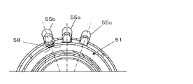
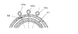
回収配管55(55a〜55c)は、図3に示されるように、端部の開口をカップ体51側に向けて、廃液経路61の外周壁部61bに挿入されて支持される。回収配管55は、分離回収する処理液の種類数だけ設けられ、本実施の形態では、カップ体51の周方向に3本の配管55a、55b、55cが開口を同一高さに位置付けられる状態で設けられる。後述するように、カップ体51を、中心軸Sを中心として水平回動させることで、カップ体51の流出孔部58を処理液の種類に応じた、1つの回収配管55a(55b、55c)の開口端部の位置に位置付けることができ、処理液の種類に応じた回収が可能となる。 As shown in FIG. 3, the recovery pipe 55 (55a to 55c) is inserted into and supported by the outer peripheral wall portion 61b of the waste liquid path 61 with the opening at the end facing the cup body 51 side. The recovery pipe 55 is provided for each type of treatment liquid to be separated and recovered, and in the present embodiment, the three pipes 55a, 55b, 55c are positioned at the same height in the circumferential direction of the cup body 51. It will be provided. As will be described later, by rotating the cup body 51 horizontally about the central axis S, the outflow hole portion 58 of the cup body 51 can be made into one recovery pipe 55a (55b, 55c) according to the type of the treatment liquid. It can be positioned at the position of the open end of the treatment liquid, and can be collected according to the type of treatment liquid.

図1において、カップ体51の下には環状容器とされる廃液経路61が設けられている。廃液経路61は、基板回転軸Sを中心とする環状の内周壁部61a、外周壁部61b及び周底部61cから成る容器であり、周底部61cには、処理液を廃液として外部に流出させる廃液配管62が接続されている。廃液経路61は廃液を貯留するためのものではなく、流出孔部58から流入した廃液を廃液配管62に導くための容器である。廃液経路61及び廃液配管62で廃液路を構成する。なお、廃液経路61は、全体或いは少なくとも処理液が流入する部分が撥水性および耐薬液性の材料で形成されるか、処理液に接する表面がフッ素樹脂でコーティングされていても良い。 In FIG. 1, a waste liquid path 61, which is an annular container, is provided under the cup body 51. The waste liquid path 61 is a container composed of an annular inner peripheral wall portion 61a centered on the substrate rotation axis S, an outer peripheral wall portion 61b, and a peripheral bottom portion 61c. The pipe 62 is connected. The waste liquid path 61 is not for storing the waste liquid, but is a container for guiding the waste liquid flowing from the outflow hole portion 58 to the waste liquid pipe 62. The waste liquid passage 61 and the waste liquid pipe 62 form a waste liquid passage. In the waste liquid path 61, the entire surface or at least the portion into which the treatment liquid flows may be formed of a water-repellent and chemical-resistant material, or the surface in contact with the treatment liquid may be coated with a fluororesin.

基板12に供給された処理液の他に、当該処理液により発生した気体(当該処理液のミストを含む気体)は、可動液受け部材53の内周壁部53bとカップ体51の外周壁部51bとの隙間を通り、カップ体51の外周面に形成された凹部の排気隙間63(図1、図9B参照)の外側に位置する排気配管65を介して排気されるようになっている。 In addition to the treatment liquid supplied to the substrate 12, the gas generated by the treatment liquid (the gas containing the mist of the treatment liquid) is the inner peripheral wall portion 53b of the movable liquid receiving member 53 and the outer peripheral wall portion 51b of the cup body 51. The gas is exhausted through the exhaust pipe 65 located outside the exhaust gap 63 (see FIGS. 1 and 9B) of the recess formed on the outer peripheral surface of the cup body 51.

図3に示すように、第1実施形態において、排気配管65(65a〜65c)は、3本の排気配管65a、65b、65cを有する。各排気配管65a〜65cは、一端が、排液通路の61の外周壁部61bの内面に開口し、他端は吸引装置(不図示)に接続される。外周壁部61bにおいて、排気配管65aの開口は、平面視で、先に述べた回収配管55aの挿入部(接続部)と対向する位置に配置される。同様に、排気配管65bの開口は、回収配管55bの挿入部(接続部)と対向する位置、排気配管65cの開口は、回収配管55cの挿入部(接続部)と対向する位置にそれぞれ配置されている。カップ体51が昇降手段54により上下方向における高位置(第1の高さ位置)にあるとき、カップ体51を後述する回動手段により水平回動させて、流出孔部58を回収配管55aの開口端部に向けると、流出孔部58の対称となる位置、つまり、180度反対側に形成された排気隙間63が排気配管65aの開口端部に向けられる配置となっている。また、カップ体51を水平回動させ、流出孔部58を回収配管55bの開口端部に向けると、排気隙間63が排気配管65bの開口端部に向けられ、更に流出孔部58を回収配管55cの開口端部に向けると、排気隙間63が排気配管65cの開口端部に向けられる配置となっている。これにより、カップ体51に流入した処理液を、流出孔部58から回収配管55(55a〜55c)を介して回収すると共に、ミスト状の処理液を含む気体を排気隙間63より排気配管65(65a〜65c)を介して外部へ排気することができるので、処理液の分別回収、処理液を含む気体の分別排気が可能となるように形成されている。 As shown in FIG. 3, in the first embodiment, the exhaust pipe 65 (65a to 65c) has three exhaust pipes 65a, 65b, 65c. One end of each of the exhaust pipes 65a to 65c opens to the inner surface of the outer peripheral wall portion 61b of the drainage passage 61, and the other end is connected to a suction device (not shown). In the outer peripheral wall portion 61b, the opening of the exhaust pipe 65a is arranged at a position facing the insertion portion (connection portion) of the recovery pipe 55a described above in a plan view. Similarly, the opening of the exhaust pipe 65b is arranged at a position facing the insertion portion (connection portion) of the recovery pipe 55b, and the opening of the exhaust pipe 65c is arranged at a position facing the insertion portion (connection portion) of the recovery pipe 55c. ing. When the cup body 51 is in a high position (first height position) in the vertical direction by the elevating means 54, the cup body 51 is horizontally rotated by the rotating means described later, and the outflow hole portion 58 is collected by the recovery pipe 55a. When facing the open end, the symmetrical position of the outflow hole 58, that is, the exhaust gap 63 formed on the opposite side of 180 degrees is arranged so as to face the open end of the exhaust pipe 65a. Further, when the cup body 51 is horizontally rotated and the outflow hole portion 58 is directed to the open end portion of the recovery pipe 55b, the exhaust gap 63 is directed to the open end portion of the exhaust pipe 65b, and the outflow hole portion 58 is further directed to the recovery pipe. When facing the open end of 55c, the exhaust gap 63 is arranged to face the open end of the exhaust pipe 65c. As a result, the treatment liquid that has flowed into the cup body 51 is recovered from the outflow hole portion 58 through the recovery pipes 55 (55a to 55c), and the gas containing the mist-like treatment liquid is collected from the exhaust gap 63 through the exhaust pipe 65 ( Since it can be exhausted to the outside via 65a to 65c), it is formed so that the treatment liquid can be separately collected and the gas containing the treatment liquid can be separately exhausted.

図9Aに示すように、回収配管55(55a〜55c)の開口端部は、カップ体51の外周壁部51bに当接しており、カップ体51は、回収配管55の端部開口に摺動可能となっている。図9Aにおいては、カップ体51の流出孔部58(破線で示す)から回収配管55aに処理液が流れるようになる。また、図9Bに示すように、排気配管65(65a〜65c)の開口端部は、廃液経路61の外周壁部61bに挿入されており、カップ体51に流入した気体が外周壁部51bと廃液経路61の外周壁部61bとの間に形成される排気隙間63(破線で示す)を通じて排気配管65に流れるようになっている。なお、排気隙間63は上下方向に所定長さで形成されており、カップ体51が上下に昇降して高位置(第1の高さ位置)、低位置(第2の高さ位置)のいずれとなっても選択した同じ排気配管65(65a〜65c)に気体が流れることになる。 As shown in FIG. 9A, the opening end of the recovery pipe 55 (55a to 55c) is in contact with the outer peripheral wall portion 51b of the cup body 51, and the cup body 51 slides on the end opening of the recovery pipe 55. It is possible. In FIG. 9A, the treatment liquid flows from the outflow hole portion 58 (indicated by the broken line) of the cup body 51 to the recovery pipe 55a. Further, as shown in FIG. 9B, the open end portion of the exhaust pipe 65 (65a to 65c) is inserted into the outer peripheral wall portion 61b of the waste liquid path 61, and the gas flowing into the cup body 51 is the outer peripheral wall portion 51b. It flows to the exhaust pipe 65 through the exhaust gap 63 (indicated by the broken line) formed between the waste liquid path 61 and the outer peripheral wall portion 61b. The exhaust gap 63 is formed to have a predetermined length in the vertical direction, and the cup body 51 moves up and down to move up and down to either a high position (first height position) or a low position (second height position). Even if it becomes, gas will flow through the same exhaust pipe 65 (65a to 65c) selected.

また、図2、図4に示すように、カップ体51が上下方向の低位置(第2の高さ位置)にあるとき、カップ体51を後述する回動手段により水平回動させて、平面視で、流出孔部58を回収配管55aの開口端部に向けると、流出孔部58の180度反対側に形成された排気隙間63が排気配管65aの開口端部に向けられる配置となるように形成されている。このとき、流出孔部58は廃液経路61の内部に位置するので、カップ体51が受け入れた処理液は、流出孔部58を通じて廃液経路61へと流れ、更に廃液経路61から廃液配管62を通じて外部へと送られるようになっている。ミスト状となった当該処理液を含む気体は、可動液受け部53材の内周壁部53bとカップ体51の外周壁部51bとの隙間を通り、カップ体51に形成される排気隙間63から、その外側に位置する排気配管65aの開口端を通じて排気配管65aに流出して外部に排気されることになる。また、流出孔部58を、平面視で、回収配管55bの開口端部に向けると、排気隙間63が排気配管65bの開口端部に向けられ、更に流出孔部58を回収配管55cの開口端部に向けると、排気隙間63が排気配管65cの開口端部に向けられる。これにより、低位置にあるカップ体51に流入した処理液を、流出孔部58から廃液経路61に流すと共に、低位置にあるカップ体51を水平回動させることで処理液により生じた気体を排気隙間63より排気配管65a〜65cのいずれかにで回収して外部へ排気することができるようになっているので、処理液の廃液と、処理液により生じた気体の分別排気とが可能となる。 Further, as shown in FIGS. 2 and 4, when the cup body 51 is in a low position (second height position) in the vertical direction, the cup body 51 is horizontally rotated by a rotation means described later to be a flat surface. Visually, when the outflow hole 58 is directed toward the open end of the recovery pipe 55a, the exhaust gap 63 formed 180 degrees opposite to the outflow hole 58 is arranged so as to be directed toward the open end of the exhaust pipe 65a. Is formed in. At this time, since the outflow hole portion 58 is located inside the waste liquid path 61, the treatment liquid received by the cup body 51 flows to the waste liquid path 61 through the outflow hole portion 58, and further from the waste liquid path 61 to the outside through the waste liquid pipe 62. It is supposed to be sent to. The gas containing the treatment liquid in the form of mist passes through the gap between the inner peripheral wall portion 53b of the movable liquid receiving portion 53 material and the outer peripheral wall portion 51b of the cup body 51, and from the exhaust gap 63 formed in the cup body 51. , It flows out to the exhaust pipe 65a through the open end of the exhaust pipe 65a located on the outside thereof and is exhausted to the outside. Further, when the outflow hole 58 is directed toward the open end of the recovery pipe 55b in a plan view, the exhaust gap 63 is directed toward the open end of the exhaust pipe 65b, and the outflow hole 58 is further directed to the open end of the recovery pipe 55c. When facing the portion, the exhaust gap 63 is directed toward the open end of the exhaust pipe 65c. As a result, the treatment liquid that has flowed into the cup body 51 at the low position is flowed from the outflow hole portion 58 to the waste liquid path 61, and the gas generated by the treatment liquid is generated by horizontally rotating the cup body 51 at the low position. Since it can be collected from the exhaust gap 63 in any of the exhaust pipes 65a to 65c and exhausted to the outside, it is possible to separate and exhaust the waste liquid of the treatment liquid and the gas generated by the treatment liquid. Become.

カップ体51の昇降手段54について、図1に図8を加えて説明する。カップ体51の周底部51cの外側表面には、ベース板23に対して垂直方向に設けられた昇降軸67の上端が接続し、下端が回動リング68(回動部)に接続されている。昇降軸67は、カップ体51の周方向120度間隔で設けられた3本の棒状部材である。昇降軸67は、ベース板23、廃液経路61の周底部61cに設けた周方向の円弧状の溝23aに沿って移動可能(所定の角度R:図8参照)に貫通されている。回動リング68は、板状のリング部材であり、内周側に周方向60度間隔で回動可能に6個のローラ71が設けられ、回動リング68の外周側に設けたモータ69(駆動部)により、ローラ71が断面L型のリング部材である昇降ユニット72上を水平回動する構造となっている。モータ69は、回動リング68を介して、カップ体51を所定の角度Rの範囲で移動するように回動駆動する。また、上記した回動リング68の水平回動を支えるべく、周方向60度間隔でかつ隣接するローラ71、71間において、ガイドローラ73が昇降ユニット72に設けられる。昇降ユニット72は、伸縮シリンダ75の駆動により、昇降ユニット72に接続される昇降ガイド76が上下方向に起立する柱部材77のレール77aに沿って移動することにより、昇降可能とされる。昇降ユニット72の昇降動は、回動リング68、昇降軸67を介してカップ体51を上下方向に昇降させることになる。昇降軸67、回動リング68、モータ69及びローラ71は、カップ体51の回動手段74を構成する。また、昇降軸67、昇降ユニット72、伸縮シリンダ75、昇降ガイド76、柱部材77及びレール77aは、カップ体51の昇降手段54を構成する。なお、モータ69と伸縮シリンダ75は、制御部100に電気的に接続されており、その駆動を制御部100に記憶された基板処理情報や各種プログラムに基づいて制御される。 The elevating means 54 of the cup body 51 will be described with reference to FIG. 1 and FIG. The upper end of the elevating shaft 67 provided in the direction perpendicular to the base plate 23 is connected to the outer surface of the peripheral bottom portion 51c of the cup body 51, and the lower end is connected to the rotating ring 68 (rotating portion). .. The elevating shaft 67 is three rod-shaped members provided at intervals of 120 degrees in the circumferential direction of the cup body 51. The elevating shaft 67 is movably penetrated along a circumferential arcuate groove 23a provided in the peripheral bottom portion 61c of the base plate 23 and the waste liquid path 61 (predetermined angle R: see FIG. 8). The rotating ring 68 is a plate-shaped ring member, and six rollers 71 rotatably provided on the inner peripheral side at intervals of 60 degrees in the circumferential direction are provided, and a motor 69 provided on the outer peripheral side of the rotating ring 68 ( The drive unit) has a structure in which the roller 71 horizontally rotates on the elevating unit 72, which is a ring member having an L-shaped cross section. The motor 69 is rotationally driven so as to move the cup body 51 within a range of a predetermined angle R via the rotating ring 68. Further, in order to support the horizontal rotation of the rotation ring 68 described above, a guide roller 73 is provided in the elevating unit 72 at intervals of 60 degrees in the circumferential direction and between the adjacent rollers 71 and 71. The elevating unit 72 can be elevated by driving the telescopic cylinder 75 so that the elevating guide 76 connected to the elevating unit 72 moves along the rail 77a of the pillar member 77 that stands up in the vertical direction. The elevating movement of the elevating unit 72 causes the cup body 51 to be elevated and lowered in the vertical direction via the rotating ring 68 and the elevating shaft 67. The elevating shaft 67, the rotating ring 68, the motor 69, and the roller 71 constitute the rotating means 74 of the cup body 51. Further, the elevating shaft 67, the elevating unit 72, the telescopic cylinder 75, the elevating guide 76, the pillar member 77, and the rail 77a constitute the elevating means 54 of the cup body 51. The motor 69 and the telescopic cylinder 75 are electrically connected to the control unit 100, and their drive is controlled based on the substrate processing information stored in the control unit 100 and various programs.

次に、本実施形態に係る基板処理装置11を用いた基板12の処理の手順について以下に説明する。基板処理装置11では、使用する処理液として、処理液A(エッチング液:リン酸溶液)、処理液B(アルカリ洗浄液:APM(アンモニアと過酸化水素水の混合液))、処理液C(有機溶剤:IPA(イソプロピルアルコール))が順に用いられる。基板処理装置11の可動液受け部材53を基板搬送ロボット(不図示)との接触を防止するために、予め不図示の昇降駆動機構により所定位置まで降下させる。そして、搬送ロボットにより未処理の基板12が基板処理装置11に搬入され、クランプピン18によって保持される。基板12が搬入された後、搬送ロボットが退避すると、基板12の回転による処理液の装置外への飛散防止のために、可動液受け部材53が上昇位置に戻される。 Next, the procedure for processing the substrate 12 using the substrate processing apparatus 11 according to the present embodiment will be described below. In the substrate processing apparatus 11, the processing liquid A (etching liquid: phosphoric acid solution), the treatment liquid B (alkaline cleaning liquid: APM (mixed liquid of ammonia and hydrogen peroxide solution)), and the treatment liquid C (organic) are used as the treatment liquid. Solvent: IPA (isopropyl alcohol)) is used in order. In order to prevent contact with the substrate transfer robot (not shown), the movable liquid receiving member 53 of the substrate processing device 11 is lowered to a predetermined position by an elevating drive mechanism (not shown) in advance. Then, the unprocessed substrate 12 is carried into the substrate processing apparatus 11 by the transfer robot and held by the clamp pin 18. When the transfer robot retracts after the substrate 12 is carried in, the movable liquid receiving member 53 is returned to the ascending position in order to prevent the processing liquid from scattering to the outside of the device due to the rotation of the substrate 12.

搬送ロボットにより基板12を基板処理装置11に供給する前は、クランプピン18は開放状態になっている。クランプピン18が開放状態にあるとき、未処理の基板12が図示しない搬送ロボットによってクランプピン18の肩部に載置される。基板12がクランプピン18に供給、配置されたなら、既に述べた動作により、基板12がクランプピン12によって保持されることになる。 Before the substrate 12 is supplied to the substrate processing device 11 by the transfer robot, the clamp pin 18 is in an open state. When the clamp pin 18 is in the open state, the unprocessed substrate 12 is placed on the shoulder of the clamp pin 18 by a transfer robot (not shown). If the substrate 12 is supplied and placed on the clamp pin 18, the substrate 12 will be held by the clamp pin 12 by the operation described above.

次に、カップ体51が第2の高さ位置に位置している状態で、カップ体51をモータ69の作動により水平回動させ、流出孔部58を回収配管55aの端部開口の真下の位置に移動させる。伸縮シリンダ75の作動によりカップ体51を上昇させて、処理液Aを回収する位置、すなわちカップ体51の流出孔部58を、処理液Aを回収する回収配管55aの端部開口と連通する高位置(第1の高さ位置)に配置する(図5A参照)。カップ体51が上記した処理液Aを回収する位置に配置された後、駆動モータ22を作動させて回転体13と共に基板12を処理液Aによる処理に最適な回転数に回転させる。 Next, with the cup body 51 located at the second height position, the cup body 51 is horizontally rotated by the operation of the motor 69, and the outflow hole portion 58 is directly below the end opening of the recovery pipe 55a. Move to position. The position where the cup body 51 is raised by the operation of the telescopic cylinder 75 to collect the treatment liquid A, that is, the height at which the outflow hole portion 58 of the cup body 51 communicates with the end opening of the recovery pipe 55a for collecting the treatment liquid A. Place in position (first height position) (see FIG. 5A). After the cup body 51 is arranged at the position where the processing liquid A is collected, the drive motor 22 is operated to rotate the substrate 12 together with the rotating body 13 to the optimum rotation speed for the processing by the processing liquid A.

処理液Aを供給するノズル20aが、待機位置から基板12の表面中心(基板回転軸S上)の上方に移動して、処理液Aを基板12の表面に予め設定した処理時間だけ供給する。基板12に供給された処理液Aは、回転する基板12上を遠心力により基板12の中心から周囲に広がり、基板12の端部から飛散する。飛散した処理液Aは、可動液受け部材53の内周壁部53bに当たり、可動液受け部材53の内周壁部53bと回転体13の側壁部13aとの間を落下してカップ体51に流れ込む。カップ体51の流出孔部58が、回収配管55aの端部の開口に連通する高位置にあるので、カップ体51内の処理液Aは流出孔部58から回収配管55aに流れ込み(図5A参照)、回収配管55aが接続する処理液Aの回収槽(不図示)へと回収される(処理液Aの回収)。 The nozzle 20a for supplying the processing liquid A moves above the surface center of the substrate 12 (on the substrate rotation axis S) from the standby position, and supplies the processing liquid A to the surface of the substrate 12 for a preset processing time. The processing liquid A supplied to the substrate 12 spreads on the rotating substrate 12 from the center of the substrate 12 to the periphery by centrifugal force, and scatters from the end portion of the substrate 12. The scattered treatment liquid A hits the inner peripheral wall portion 53b of the movable liquid receiving member 53, falls between the inner peripheral wall portion 53b of the movable liquid receiving member 53 and the side wall portion 13a of the rotating body 13, and flows into the cup body 51. Since the outflow hole portion 58 of the cup body 51 is located at a high position communicating with the opening at the end of the recovery pipe 55a, the treatment liquid A in the cup body 51 flows from the outflow hole portion 58 into the recovery pipe 55a (see FIG. 5A). ), It is recovered to the recovery tank (not shown) of the treatment liquid A to which the recovery pipe 55a is connected (recovery of the treatment liquid A).

カップ体51の流出孔部58が回収配管55aの開口端部の開口に連通する位置にあるときは、カップ体51の外周壁部51bに形成される隙間空間63が排気配管65aの開口端部の開口(排気配管65aの一端)と連通する位置にあり(図6A参照)、処理液Aのミストを含む気体(処理液Aの排気)が隙間空間63を経由して排気配管65aに流れ、排気配管65aが接続する処理液Aの回収槽(不図示)へ流れ、排気回収される(処理液Aの排気回収)。なお、流出孔部58が回収配管55aの開口に連通する高位置にあるカップ体51が、水平回動せずにそのまま降下した低位置(第2の高さ位置)にあるときも隙間空間63は排気配管65aの開口端部の開口と連通する位置にある。 When the outflow hole portion 58 of the cup body 51 is in a position communicating with the opening of the opening end portion of the recovery pipe 55a, the gap space 63 formed in the outer peripheral wall portion 51b of the cup body 51 is the opening end portion of the exhaust pipe 65a. (See FIG. 6A), the gas containing the mist of the treatment liquid A (exhaust of the treatment liquid A) flows into the exhaust pipe 65a via the gap space 63. It flows into a recovery tank (not shown) of the processing liquid A to which the exhaust pipe 65a is connected, and is exhaust-recovered (exhaust recovery of the treatment liquid A). Even when the cup body 51 at a high position where the outflow hole portion 58 communicates with the opening of the recovery pipe 55a is at a low position (second height position) where the cup body 51 descends as it is without horizontal rotation, the gap space 63 Is in a position communicating with the opening at the opening end of the exhaust pipe 65a.

次に、処理液Aによる基板12の処理が終了すると、ノズル20aから処理液Aの供給が停止され、ノズル20aを基板12の中心から待機位置へと退避させる。伸縮シリンダ75を作動させてロッド75aを縮めることで昇降ガイド76を降下させると、昇降軸67によりカップ体51の位置が低位置(第2の高さ位置)に下降する(図2参照)。これにより、カップ体51の流出孔部58は、廃液経路61の内部に面する位置に位置づけられる。そして、ノズル20dを待機位置から基板12の中心の上方へと移動させ、ノズル20dから基板12の洗浄用のリンス液として純水が回転する基板12の表面に予め設定した時間だけ供給される。なお、基板12の回転数は、予め純水による洗浄に適した回転数に設定されている。基板12に供給された純水は、遠心力により基板12上を中央から端部に向けて広がり、基板12上に残留した処理液Aと共に基板12の端部から飛散して、可動液受け部材53の内周壁部53bに当たり、可動液受け部材53の内周壁部53bと回転体13の側壁部13aとの間を落下してカップ体51に流入する。カップ体51に流入した処理液Aを含む純水は、カップ体51内に残留する処理液Aを含んで流出孔部58から廃液経路61に流出し、廃液経路61に接続する廃液配管62を通じて廃液槽(不図示)へと流れ込み、廃液される。したがって、カップ体51内に残留する処理液Aを純水によって洗い流されることになる。なお、純水が供給される時間は、後述するカップ体51内に残留する処理液Aを純水によって廃液することが可能な時間に設定されている。さらに、隙間空間63は排気配管65aの開口端部の開口と連通する位置にあるので、処理液Aの排気は排気配管65aに流出し、処理液Aの回収槽(不図示)へ流れる。なお、カップ体51内に純水が流入する時、純水のミストが発生し、純水のミストを含む気体が排気配管65aに流出することになるが、処理液Aの排気を薄める程度のものであり、処理液Aの排気を回収するのに支障をきたさないものである。 Next, when the processing of the substrate 12 by the processing liquid A is completed, the supply of the processing liquid A is stopped from the nozzle 20a, and the nozzle 20a is retracted from the center of the substrate 12 to the standby position. When the elevating guide 76 is lowered by operating the telescopic cylinder 75 and contracting the rod 75a, the position of the cup body 51 is lowered to a low position (second height position) by the elevating shaft 67 (see FIG. 2). As a result, the outflow hole portion 58 of the cup body 51 is positioned at a position facing the inside of the waste liquid path 61. Then, the nozzle 20d is moved from the standby position to the upper part of the center of the substrate 12, and pure water is supplied from the nozzle 20d to the surface of the rotating substrate 12 as a rinse liquid for cleaning the substrate 12 for a preset time. The rotation speed of the substrate 12 is set in advance to a rotation speed suitable for cleaning with pure water. The pure water supplied to the substrate 12 spreads on the substrate 12 from the center toward the end due to centrifugal force, and scatters from the end of the substrate 12 together with the treatment liquid A remaining on the substrate 12, and is a movable liquid receiving member. It hits the inner peripheral wall portion 53b of the 53, falls between the inner peripheral wall portion 53b of the movable liquid receiving member 53 and the side wall portion 13a of the rotating body 13, and flows into the cup body 51. The pure water containing the treatment liquid A flowing into the cup body 51 contains the treatment liquid A remaining in the cup body 51 and flows out from the outflow hole portion 58 to the waste liquid path 61, and passes through the waste liquid pipe 62 connected to the waste liquid path 61. It flows into a waste liquid tank (not shown) and is drained. Therefore, the treatment liquid A remaining in the cup body 51 is washed away with pure water. The time for supplying pure water is set to a time during which the treatment liquid A remaining in the cup body 51, which will be described later, can be drained with pure water. Further, since the gap space 63 is in a position communicating with the opening at the opening end of the exhaust pipe 65a, the exhaust of the treatment liquid A flows out to the exhaust pipe 65a and flows to the recovery tank (not shown) of the treatment liquid A. When pure water flows into the cup body 51, a mist of pure water is generated, and a gas containing the mist of pure water flows out to the exhaust pipe 65a, but the exhaust of the processing liquid A is diluted. It does not hinder the recovery of the exhaust gas of the treatment liquid A.

純水による洗浄が所定時間行われた後に、ノズル20dからの純水の供給が停止される。そして、カップ体51は、モータ69の作動により回動リング68に設けられたローラ71がリング状の昇降ユニット72上を水平回動して、流出孔部58を処理液Bの回収配管55bの端部開口の真下の位置に移動させる。そして、待機位置にあった処理液Bを供給するノズル20bが、基板12の表面中心の上方に移動して、処理液Bを基板12の表面に予め設定した時間だけ供給する。供給された処理液Bは、回転する基板12上を残留した純水と共に遠心力により基板12の中央から周囲に広がり、そして基板12の端部から飛散する。飛散した純水を含む処理液Bは落下してカップ体51に流れ込み、そしてカップ体51内に残留する純水を含めて流出孔部58から廃液経路61に流出し、廃液配管62を通じて廃液槽(不図示)へと流れ込み、廃液される。なお、隙間空間63は排気配管65bの開口端部の開口と連通する位置にあるので、処理液Bの排気は排気配管65bに流出し、処理液Bの回収槽(不図示)へ流れる。 After cleaning with pure water for a predetermined time, the supply of pure water from the nozzle 20d is stopped. Then, in the cup body 51, the roller 71 provided on the rotating ring 68 rotates horizontally on the ring-shaped elevating unit 72 by the operation of the motor 69, and the outflow hole portion 58 is formed in the recovery pipe 55b of the processing liquid B. Move it to a position just below the end opening. Then, the nozzle 20b for supplying the processing liquid B in the standby position moves above the center of the surface of the substrate 12 and supplies the processing liquid B to the surface of the substrate 12 for a preset time. The supplied treatment liquid B spreads from the center of the substrate 12 to the periphery by centrifugal force together with the pure water remaining on the rotating substrate 12, and is scattered from the end portion of the substrate 12. The treatment liquid B containing the scattered pure water falls and flows into the cup body 51, and the pure water remaining in the cup body 51 flows out from the outflow hole portion 58 to the waste liquid path 61, and flows out to the waste liquid path 61 through the waste liquid pipe 62. It flows into (not shown) and is drained. Since the gap space 63 is in a position communicating with the opening at the opening end of the exhaust pipe 65b, the exhaust of the treatment liquid B flows out to the exhaust pipe 65b and flows to the recovery tank (not shown) of the treatment liquid B.

処理液Bの供給開始から予め設定した所定時間が経過すると、カップ体51内に残留する純水は、既に処理液Bによって押し流され、カップ体51内には処理液Bだけが存在することになる。伸縮シリンダ75のシリンダロッド75aの伸長により、低位置にあるカップ体51が上昇し、流出孔部58が、回収配管55bの端部の開口に連通する高位置(第1の高さ位置)へと移動する。この第1実施形態では、カップ体51が第2の高さ位置から第1の高さ位置に上昇する間、基板12に対するノズル20bからの処理液Bの供給は継続される。なお、カップ体51の上昇する間だけ、ノズル20bからの処理液Bの供給を一時的に停止させても良いが、基板に対する均一処理の観点からは、カップ体51の上昇する間も処理液を基板12に対して供給し続ける方が好ましい。カップ体51が第1の高さ位置で、流出孔部58が、回収配管55bの端部の開口に連通すると、カップ体51内の処理液Bは流出孔部58より回収配管55bに流れ込み(図5B参照)、回収配管55bが接続する処理液Bの回収槽(不図示)へと回収される(処理液Bの回収)。このとき、カップ体51の外周壁部51bに形成される隙間空間63は排気配管65bの端部の開口と連通する位置にあり(図6B参照)、処理液Bのミストを含む気体(処理液Bの排気)が隙間空間63を経由して排気配管65bに流れ、排気配管65bが接続する処理液Bの回収槽(不図示)へ流れ、排気回収される(処理液Bの排気回収)。 When a predetermined time has elapsed from the start of supply of the treatment liquid B, the pure water remaining in the cup body 51 has already been washed away by the treatment liquid B, and only the treatment liquid B exists in the cup body 51. Become. Due to the extension of the cylinder rod 75a of the telescopic cylinder 75, the cup body 51 at the low position rises, and the outflow hole portion 58 communicates with the opening at the end of the recovery pipe 55b to a high position (first height position). And move. In this first embodiment, the supply of the treatment liquid B from the nozzle 20b to the substrate 12 is continued while the cup body 51 rises from the second height position to the first height position. The supply of the treatment liquid B from the nozzle 20b may be temporarily stopped only while the cup body 51 rises, but from the viewpoint of uniform treatment on the substrate, the treatment liquid may also be temporarily stopped while the cup body 51 rises. Is preferably continued to be supplied to the substrate 12. When the cup body 51 communicates with the opening at the end of the recovery pipe 55b at the first height position, the treatment liquid B in the cup body 51 flows from the outflow hole portion 58 into the recovery pipe 55b ( (See FIG. 5B), the treatment liquid B is collected in a recovery tank (not shown) to which the recovery pipe 55b is connected (recovery of the treatment liquid B). At this time, the gap space 63 formed in the outer peripheral wall portion 51b of the cup body 51 is located at a position communicating with the opening at the end of the exhaust pipe 65b (see FIG. 6B), and is a gas containing the mist of the treatment liquid B (treatment liquid). (Exhaust of B) flows to the exhaust pipe 65b via the gap space 63, flows to the recovery tank (not shown) of the treatment liquid B to which the exhaust pipe 65b is connected, and is exhaust-recovered (exhaust recovery of the treatment liquid B).

処理液Bによる基板12の処理が終了すると、ノズル20bから処理液Bの供給が停止され、ノズル20bを基板12の中心上部から待機位置へと退避させる。伸縮シリンダ75を作動させてシリンダロッド75aを縮めることで、昇降ガイド76を降下させると、昇降軸67と共にカップ体51の位置が低位置に下降する。低位置となったカップ体51の流出孔部58は、廃液経路61の内部に面する位置に位置づけられる。そして、再度ノズル20dを待機位置から基板12の中心上方へと移動させ、ノズル20dから純水が基板12の表面に予め設定した時間だけ供給される。回転する基板12に供給された純水は、遠心力により基板12上を中心から端部に向けて広がり、基板12上に残留した処理液Bと共に基板12の端部から飛散して、可動液受け部材53の内周壁部53bに当たり、可動液受け部材53の内周壁部53bと回転体13の側壁部13aとの間を落下してカップ体51に流入する。カップ体51に流入した、処理液Bを含む純水は、更にカップ体51内に残留する処理液Bを含んでカップ体51の流出孔部58から廃液経路61に流出し、廃液経路61に接続する廃液配管62を通じて廃液槽(不図示)へと流れ込み、廃液される。したがって、カップ体51内に残留する処理液Bが純水によって洗い流されることになる。なお、純水が供給される時間は、後述するカップ体51内に残留する処理液Bを純水によって廃液することが可能な時間に設定されている。さらに、隙間空間63は排気配管65bの開口端部の開口と連通する位置にあるので、処理液Bの排気は排気配管65bに流出し、処理液Bの回収槽(不図示)へ流れる。なお、カップ体51内に純水が流入する時、純水のミストが発生し、純水のミストを含む気体が排気配管65bに流出することになるが、処理液Bの排気を薄める程度でのものであり、処理液Bの排気を回収するのに支障をきたさないものである。 When the processing of the substrate 12 by the processing liquid B is completed, the supply of the processing liquid B is stopped from the nozzle 20b, and the nozzle 20b is retracted from the upper center of the substrate 12 to the standby position. When the elevating guide 76 is lowered by operating the telescopic cylinder 75 to contract the cylinder rod 75a, the position of the cup body 51 is lowered together with the elevating shaft 67. The outflow hole portion 58 of the cup body 51, which is in a low position, is positioned at a position facing the inside of the waste liquid path 61. Then, the nozzle 20d is moved from the standby position to the upper center of the substrate 12 again, and pure water is supplied from the nozzle 20d to the surface of the substrate 12 for a preset time. The pure water supplied to the rotating substrate 12 spreads from the center toward the end on the substrate 12 by centrifugal force, and scatters from the end of the substrate 12 together with the treatment liquid B remaining on the substrate 12, and is a movable liquid. It hits the inner peripheral wall portion 53b of the receiving member 53, falls between the inner peripheral wall portion 53b of the movable liquid receiving member 53 and the side wall portion 13a of the rotating body 13, and flows into the cup body 51. The pure water containing the treatment liquid B that has flowed into the cup body 51 further contains the treatment liquid B remaining in the cup body 51 and flows out from the outflow hole portion 58 of the cup body 51 to the waste liquid path 61 and into the waste liquid path 61. It flows into a waste liquid tank (not shown) through the connected waste liquid pipe 62 and is discharged. Therefore, the treatment liquid B remaining in the cup body 51 is washed away by pure water. The time for supplying pure water is set to a time during which the treatment liquid B remaining in the cup body 51, which will be described later, can be drained with pure water. Further, since the gap space 63 is in a position communicating with the opening at the opening end of the exhaust pipe 65b, the exhaust of the treatment liquid B flows out to the exhaust pipe 65b and flows to the recovery tank (not shown) of the treatment liquid B. When pure water flows into the cup body 51, a mist of pure water is generated, and a gas containing the mist of pure water flows out to the exhaust pipe 65b. It does not hinder the recovery of the exhaust gas of the treatment liquid B.

純水による洗浄が所定時間行われた後に、ノズル20dからの純水の供給が停止される。そして、カップ体51は、モータ69の作動により回動リング68に設けられたローラ71がリング状の昇降ユニット72上を水平回動して、流出孔部58を処理液Cの回収配管55cの端部開口の真下の位置に移動する。そして、処理液Cを供給するノズル20cが、待機位置から基板12の表面中心の上方に移動して、処理液Cを基板12に予め設定した処理時間だけ供給する。供給された処理液Cは、回転する基板12上を残留した純水と共に遠心力により基板12の中心から周囲に広がり、そして基板12の端部から飛散し、可動液受け部材53の内周壁部53bに当たり、可動液受け部材53の内周壁部53bと回転体13の側壁部13aとの間を落下してカップ体51に流れ込み、そしてカップ体51内に残留する純水を含めて流出孔部58から廃液経路61に流出し、廃液配管62を通じて廃液槽(不図示)へと流れ込み、廃液される。なお、隙間空間63は排気配管65cの開口端部の開口と連通する位置にあるので、処理液Cの排気は排気配管65cに流出し、処理液Cの回収槽(不図示)へ流れる。 After cleaning with pure water for a predetermined time, the supply of pure water from the nozzle 20d is stopped. Then, in the cup body 51, the roller 71 provided on the rotating ring 68 rotates horizontally on the ring-shaped elevating unit 72 by the operation of the motor 69, and the outflow hole portion 58 is formed in the recovery pipe 55c of the processing liquid C. Move to a position just below the end opening. Then, the nozzle 20c for supplying the processing liquid C moves above the surface center of the substrate 12 from the standby position, and supplies the processing liquid C to the substrate 12 for a preset processing time. The supplied treatment liquid C spreads from the center of the substrate 12 to the surroundings by centrifugal force together with the pure water remaining on the rotating substrate 12, and scatters from the end portion of the substrate 12, and the inner peripheral wall portion of the movable liquid receiving member 53. When it hits 53b, it falls between the inner peripheral wall portion 53b of the movable liquid receiving member 53 and the side wall portion 13a of the rotating body 13 and flows into the cup body 51, and the outflow hole portion including the pure water remaining in the cup body 51. It flows out from 58 to the waste liquid path 61, flows into the waste liquid tank (not shown) through the waste liquid pipe 62, and is discharged. Since the gap space 63 is in a position communicating with the opening at the opening end of the exhaust pipe 65c, the exhaust of the treatment liquid C flows out to the exhaust pipe 65c and flows to the recovery tank (not shown) of the treatment liquid C.

処理液Cの供給開始から予め設定した所定時間が経過すると、カップ体51内に残留する純水は、既に処理液Cによって押し流され、カップ体51内には処理液Cだけが存在ことになる。伸縮シリンダ75のシリンダロッド75aの伸長により、低位置にあるカップ体51が上昇し、流出孔部58が、回収配管55cの端部の開口に連通する高位置へと移動する。この移動の間、基板12に対するノズル20cからの処理液Cの供給は継続される。なお、一時的に処理液Cの供給を停止させるようにしても良い。流出孔部58が、回収配管55cの端部の開口に連通すると、カップ体51内の処理液Cは流出孔部58より回収配管55cに流れ込み(図5C参照)、回収配管55cが接続する処理液Cの回収槽(不図示)へと回収される(処理液Cの回収)。このとき、カップ体51の外周壁面に形成される隙間空間63は排気配管65cの端部の開口と連通する位置にあり(図6C参照)、処理液Cのミストを含む気体が隙間空間63を経由して排気配管65cに流れ、排気配管65cが接続する処理液Cの回収槽(不図示)へ流れ、排気回収される(処理液Cの排気回収)。 When a predetermined time has elapsed from the start of supply of the treatment liquid C, the pure water remaining in the cup body 51 has already been washed away by the treatment liquid C, and only the treatment liquid C is present in the cup body 51. .. The extension of the cylinder rod 75a of the telescopic cylinder 75 raises the cup body 51 at a low position, and the outflow hole portion 58 moves to a high position communicating with the opening at the end of the recovery pipe 55c. During this movement, the supply of the treatment liquid C from the nozzle 20c to the substrate 12 is continued. The supply of the treatment liquid C may be temporarily stopped. When the outflow hole portion 58 communicates with the opening at the end of the recovery pipe 55c, the treatment liquid C in the cup body 51 flows into the recovery pipe 55c from the outflow hole portion 58 (see FIG. 5C), and the recovery pipe 55c is connected. It is recovered in a recovery tank (not shown) of the liquid C (recovery of the treatment liquid C). At this time, the gap space 63 formed on the outer peripheral wall surface of the cup body 51 is located at a position communicating with the opening at the end of the exhaust pipe 65c (see FIG. 6C), and the gas containing the mist of the treatment liquid C forms the gap space 63. It flows to the exhaust pipe 65c via the exhaust pipe 65c, flows to the recovery tank (not shown) of the processing liquid C to which the exhaust pipe 65c is connected, and is exhaust collected (exhaust recovery of the treatment liquid C).

処理液Cによる基板12の処理が終了すると、ノズル20cから処理液Cの供給が停止され、ノズル20cを基板12の中心から待機位置へと退避させる。伸縮シリンダ75を作動させてロッド75aを縮めることで、昇降ガイド76を降下させると、昇降軸67と共にカップ体51の位置が低位置(第2の高さ位置)に下降する。低位置となったカップ体51の流出孔部58は、廃液経路61の内部の位置となる。駆動モータ22、回転体13等により基板12を高速回転させ、基板12上から処理液Cを飛散させて基板12を乾燥させる。 When the processing of the substrate 12 by the processing liquid C is completed, the supply of the processing liquid C is stopped from the nozzle 20c, and the nozzle 20c is retracted from the center of the substrate 12 to the standby position. When the elevating guide 76 is lowered by operating the telescopic cylinder 75 to contract the rod 75a, the position of the cup body 51 is lowered to a low position (second height position) together with the elevating shaft 67. The outflow hole portion 58 of the cup body 51, which is in a low position, is located inside the waste liquid path 61. The substrate 12 is rotated at high speed by the drive motor 22, the rotating body 13, and the like, and the processing liquid C is scattered from the substrate 12 to dry the substrate 12.

予め設定した所定時間が経過後、乾燥処理が終了したならば、回転体13の回転を停止し、クランプピン18による基板12の保持を開放する。基板12の保持状態が解除された後、可動液受け部材53が降下し、搬送ロボット(不図示)により処理済みの基板12が外部へ搬送される。 When the drying process is completed after the predetermined time set in advance has elapsed, the rotation of the rotating body 13 is stopped, and the holding of the substrate 12 by the clamp pin 18 is released. After the holding state of the substrate 12 is released, the movable liquid receiving member 53 is lowered, and the processed substrate 12 is conveyed to the outside by a transfer robot (not shown).

次の基板処理では、カップ体51が水平回動して処理液Aの回収配管55aの端部開口の真下の位置に移動した位置から開始する。上述したように、搬送された処理前の基板12をクランプピン18で保持して回転させ、更にノズル20aが待機位置から基板12の中心上方に移動し、処理液Aを回転する基板12に供給する。このとき、基板12からカップ体51に流入した処理液Aは、カップ体51に残留する処理液Cと共に、流出孔部58から廃液経路61に流出し、廃液配管62を通じて廃液槽(不図示)へと流れ込み、廃液される。処理液Aの供給開始から予め設定した所定時間経過すると、伸縮シリンダ75のシリンダロッド75aの伸長により、廃液位置である低位置にあるカップ体51が上昇し、流出孔部58が、処理液Aの回収配管55aの端部の開口に連通する高位置へと移動して、処理液Aの回収を行う。以下は、上述した手順の工程により同様に基板12を処理液B、C及び純水で処理を行う。 In the next substrate processing, the cup body 51 starts from a position where the cup body 51 is horizontally rotated and moved to a position directly below the end opening of the recovery pipe 55a of the processing liquid A. As described above, the conveyed substrate 12 before processing is held by the clamp pin 18 and rotated, and the nozzle 20a further moves from the standby position to the upper center of the substrate 12 to supply the processing liquid A to the rotating substrate 12. do. At this time, the treatment liquid A flowing into the cup body 51 from the substrate 12 flows out from the outflow hole portion 58 to the waste liquid path 61 together with the treatment liquid C remaining in the cup body 51, and flows out to the waste liquid path 61 through the waste liquid pipe 62 (not shown). It flows into and is drained. After a predetermined time has elapsed from the start of supply of the treatment liquid A, the cup body 51 at the low position, which is the waste liquid position, rises due to the extension of the cylinder rod 75a of the telescopic cylinder 75, and the outflow hole portion 58 becomes the treatment liquid A. The treatment liquid A is recovered by moving to a high position communicating with the opening at the end of the recovery pipe 55a. In the following, the substrate 12 is similarly treated with the treatment liquids B and C and pure water according to the steps of the above-mentioned procedure.

なお、処理液Aを基板12に供給する前に、基板12にノズル20dから純水を供給し、カップ体51に残留する処理液Cを純水と共に、流出孔部58から流出させて、廃液させてもよい。これにより、処理液Aによるカップ体51に残留する処理液Cを洗浄させることがなくなり、処理液Aと処理液Cの混合液を廃液させずに済み、処理液Aを無駄なく回収することができる。 Before supplying the treatment liquid A to the substrate 12, pure water is supplied to the substrate 12 from the nozzle 20d, and the treatment liquid C remaining in the cup body 51 is discharged together with the pure water from the outflow hole portion 58 to be a waste liquid. You may let me. As a result, the treatment liquid C remaining in the cup body 51 by the treatment liquid A is not washed, the mixed liquid of the treatment liquid A and the treatment liquid C does not need to be wasted, and the treatment liquid A can be recovered without waste. can.

本実施形態において、処理液の切り替え回収に際しては、カップ体51の流出孔部58を廃液経路61の内部の位置(第2の高さ位置)に位置づけるように下降させて、混合した処理液を廃液させてから、流出孔部を処理液ごとの回収配管の端部の開口に連通する位置(第1の高さ位置)へと移動させるので、カップ体51の水平回動により流出孔部58が、回収する処理液以外の回収配管の開口上を通過することがないので、他の処理液が混入せずに目的の回収する処理液を回収することが可能となる。さらに、カップ体51の外周壁部51bに形成した排気隙間63を各処理液毎の排気配管に連通させたので、ミスト化された処理液の排気を各処理液毎に分離回収することができる。本実施形態では、処理液A、B、Cの3種類を分離回収しているが、これに限定するものではない。回収配管及び排気配管の数を増減させることで、3種類よりも多く、又は少なくして回収することができる。さらに、廃液経路の数を増やすことで、各処理液の混合液毎に廃液することもできる。また、カップ体51を、処理液の供給開始から所定時間経過後に上昇させるようにしたが、これに限らず、例えば、廃液経路61に濃度計を設け、廃液経路61に流出する処理液の濃度を測定し、処理液の濃度が所定の濃度以上に達したときに、カップ体51を上昇させるようにしてもよい。 In the present embodiment, when the treatment liquid is switched and recovered, the outflow hole portion 58 of the cup body 51 is lowered so as to be positioned at the internal position (second height position) of the waste liquid path 61, and the mixed treatment liquid is mixed. After draining the liquid, the outflow hole is moved to a position (first height position) that communicates with the opening at the end of the recovery pipe for each treatment liquid, so that the outflow hole 58 is rotated horizontally by the cup body 51. However, since it does not pass over the opening of the recovery pipe other than the treatment liquid to be recovered, it is possible to recover the target treatment liquid to be recovered without mixing with other treatment liquids. Further, since the exhaust gap 63 formed in the outer peripheral wall portion 51b of the cup body 51 is communicated with the exhaust pipe for each treatment liquid, the exhaust of the mistized treatment liquid can be separated and recovered for each treatment liquid. .. In the present embodiment, three types of treatment liquids A, B, and C are separated and recovered, but the present invention is not limited to this. By increasing or decreasing the number of recovery pipes and exhaust pipes, it is possible to collect more or less than three types. Further, by increasing the number of waste liquid routes, it is possible to waste liquid for each mixed liquid of each treatment liquid. Further, the cup body 51 is raised after a lapse of a predetermined time from the start of supply of the treatment liquid, but the present invention is not limited to this. When the concentration of the treatment liquid reaches a predetermined concentration or more, the cup body 51 may be raised.

上記した本実施形態の基板12の処理手順では、基板12の表面にノズル20(20a〜20d)から処理液を供給して基板処理を行っているが、ノズル29(29a〜29d)により基板12に処理液を噴射して基板の裏面処理を行う、両面処理も可能である。基板12の裏面処理では、各処理液は中空の管体31を通じて廃液槽へ送られる。 In the above-described processing procedure for the substrate 12 of the present embodiment, the processing liquid is supplied from the nozzles 20 (20a to 20d) to the surface of the substrate 12 to process the substrate, but the substrate 12 is processed by the nozzles 29 (29a to 29d). Double-sided treatment is also possible, in which the treatment liquid is sprayed onto the back surface of the substrate to treat the back surface. In the back surface treatment of the substrate 12, each treatment liquid is sent to the waste liquid tank through the hollow tube 31.

(第2の実施形態)
次に、本発明の第2の実施形態に係る基板処理装置11aについて、図10を参照して説明する。なお、第1の実施形態との相違点を説明し、共通点については適宜簡略する。また、第1の実施形態と共通する構成要素については、共通の名称、符号を使用して説明する。
(Second embodiment)
Next, the substrate processing apparatus 11a according to the second embodiment of the present invention will be described with reference to FIG. The differences from the first embodiment will be described, and the common points will be simplified as appropriate. Further, the components common to the first embodiment will be described using common names and reference numerals.

本実施形態では、カップ体51aに2個の流出孔部58a、58bを設け、更に2個の排気隙間63a、63bを設けたものである。流出孔部58aと流出孔部58bは、中心A(図10に示す)を軸にして対称の位置となるように配置されている。つまり、流出孔部58aの180度反対側に流出孔部58bが配置される。また、排気隙間63aと排気隙間63bは、中心Aを軸にして対称の位置になるように配置されている。つまり、排気隙間63aの180度反対側に排気隙間63bが配置される。また、カップ体の周方向に、90度毎に流出孔部58(58a、58b)と排気隙間63(63a、63b)が交互に設けられている。そして、この流出孔部58aに対応するように、回収配管55a1、55b1、55c1が設けられ、流出孔部58bに対応するように、回収配管55a2、55b2、55c2を設けられている。更に、排気隙間63aに対応するように、排気配管65a1、65b1、65c1が設けられ、排気隙間63bに対応するように、排気配管65a2、65b2、65c2が設けられている。カップ体51aを低位置(第2の位置)に下降させて、流出孔部58から廃液経路61に流出し、廃液配管62を通じて廃液槽(不図示)へと流れ込み、廃液させる点は、第1の実施形態と同様である。 In the present embodiment, the cup body 51a is provided with two outflow hole portions 58a and 58b, and further provided with two exhaust gaps 63a and 63b. The outflow hole portion 58a and the outflow hole portion 58b are arranged so as to be symmetrical with respect to the center A (shown in FIG. 10). That is, the outflow hole portion 58b is arranged 180 degrees opposite to the outflow hole portion 58a. Further, the exhaust gap 63a and the exhaust gap 63b are arranged so as to be symmetrical with respect to the center A. That is, the exhaust gap 63b is arranged on the 180-degree opposite side of the exhaust gap 63a. Further, outflow hole portions 58 (58a, 58b) and exhaust gaps 63 (63a, 63b) are alternately provided every 90 degrees in the circumferential direction of the cup body. The recovery pipes 55a1, 55b1, 55c1 are provided so as to correspond to the outflow hole portion 58a, and the recovery pipes 55a2, 55b2, 55c2 are provided so as to correspond to the outflow hole portion 58b. Further, exhaust pipes 65a1, 65b1, 65c1 are provided so as to correspond to the exhaust gap 63a, and exhaust pipes 65a2, 65b2, 65c2 are provided so as to correspond to the exhaust gap 63b. The first point is that the cup body 51a is lowered to a low position (second position), flows out from the outflow hole 58 to the waste liquid path 61, flows into the waste liquid tank (not shown) through the waste liquid pipe 62, and drains the liquid. It is the same as the embodiment of.

第1の実施形態と同様に、回収する処理液が処理液A、処理液B及び処理液Cとすると、カップ体51aを、流出孔部58a、58bをそれぞれ処理液Aの回収配管55a1、55a2の端部の開口の真下の位置に水平回動させ、更に、カップ体51を高位置(第1の高さ位置)に上昇させ、流出孔部58a、58bをそれぞれ処理液Aの回収配管55a1、55a2の端部の開口に連通する位置に移動させて処理液Aを回収する。また、このとき排気隙間63a、63bはそれぞれ処理液Aの排気を回収する排気配管65a1、65a2の端部の開口に連通する位置になり、ミスト化した処理液Aの排気を回収することができる。同様に、処理液Bの回収についても、カップ体51aを、流出孔部58a、58bをそれぞれ処理液Bの回収配管55b1、55b2の端部の開口の真下の位置に水平回動させ、更に、カップ体51を高位置(第1の高さ位置)に上昇させ、流出孔部58a、58bをそれぞれ処理液Bの回収配管55b1、55b2の端部の開口に連通する位置に移動させて処理液Bを回収する。このとき、排気隙間63a、63bはそれぞれ処理液Bの排気を回収する排気配管65b1、65b2の端部の開口に連通する位置になり、ミスト化した処理液Bの排気を回収することができる。同様に、処理液Cの回収についても、カップ体51aを、流出孔部58a、58bをそれぞれ処理液Cの回収配管55c1、55c2の端部の開口の真下の位置に水平回動させ、更に、カップ体51を高位置(第1の高さ位置)に上昇させ、流出孔部58a、58bをそれぞれ処理液Cの回収配管55c1、55c2の端部の開口に連通する位置に移動させて処理液Cを回収する。このとき、排気隙間63a、63bはそれぞれ処理液Cの排気を回収する排気配管65c1、65c2の端部の開口に連通する位置になり、ミスト化した処理液Cの排気を回収する。 As in the first embodiment, assuming that the treatment liquids to be recovered are the treatment liquid A, the treatment liquid B, and the treatment liquid C, the cup body 51a and the outflow hole portions 58a and 58b are the recovery pipes 55a1 and 55a2 of the treatment liquid A, respectively. The cup body 51 is further raised to a high position (first height position) by horizontally rotating the cup body 51 to a position directly below the opening at the end of the sluice, and the outflow holes 58a and 58b are each used as a recovery pipe 55a1 for the treatment liquid A. , 55a2 is moved to a position communicating with the opening at the end portion, and the treatment liquid A is collected. Further, at this time, the exhaust gaps 63a and 63b are at positions communicating with the openings at the ends of the exhaust pipes 65a1 and 65a2 for collecting the exhaust gas of the processing liquid A, respectively, and the exhaust gas of the processing liquid A that has become mist can be collected. .. Similarly, for the recovery of the treatment liquid B, the cup body 51a is horizontally rotated so that the outflow holes 58a and 58b are located just below the openings at the ends of the recovery pipes 55b1 and 55b2 of the treatment liquid B, respectively. The cup body 51 is raised to a high position (first height position), and the outflow holes 58a and 58b are moved to positions communicating with the openings at the ends of the recovery pipes 55b1 and 55b2 of the treatment liquid B, respectively, to move the treatment liquid. Collect B. At this time, the exhaust gaps 63a and 63b are positioned so as to communicate with the openings at the ends of the exhaust pipes 65b1 and 65b2 for collecting the exhaust gas of the processing liquid B, respectively, and the exhaust gas of the processing liquid B that has become mist can be collected. Similarly, for the recovery of the treatment liquid C, the cup body 51a is horizontally rotated so that the outflow holes 58a and 58b are located just below the openings at the ends of the recovery pipes 55c1 and 55c2 of the treatment liquid C, respectively. The cup body 51 is raised to a high position (first height position), and the outflow holes 58a and 58b are moved to positions communicating with the openings at the ends of the recovery pipes 55c1 and 55c2 of the treatment liquid C, respectively, to move the treatment liquid. Collect C. At this time, the exhaust gaps 63a and 63b are at positions communicating with the openings at the ends of the exhaust pipes 65c1 and 65c2 for collecting the exhaust gas of the processing liquid C, respectively, and collect the exhaust gas of the treated liquid C that has become mist.

本実施形態によれば、各処理液の回収と、各処理液により生じる気体とをそれぞれ複数の配管で回収、排気ができるので、分離回収、分離排気とする本来の目的に加えて、回収配管および排気配管を増やすことで、迅速に回収及び排気することが可能となる。特に、処理液を大量に供給して基板処理を行う際、カップ体51aから処理液が溢れるおそれを解消することができる。 According to the present embodiment, the recovery of each treatment liquid and the gas generated by each treatment liquid can be recovered and exhausted by a plurality of pipes, respectively. Therefore, in addition to the original purpose of separation recovery and separation exhaust, the recovery pipe And by increasing the number of exhaust pipes, it becomes possible to quickly collect and exhaust. In particular, when a large amount of processing liquid is supplied to process the substrate, it is possible to eliminate the possibility that the processing liquid overflows from the cup body 51a.

(変形例1)
次に、本発明の第1、第2の実施形態に係る基板処理装置11、11aにおけるカップ体51の変形例1について、図11を参照して説明する。カップ体51の縦断面図である図11に示すように、カップ体55の外周壁部51bの周底部51cとの接点である最下部に形成される流出孔部58の下端には、回収配管55側に向けて傾斜した突出部57が設けられている。回収配管55の流出孔部58側の開口端部には、突出部57と係合するように形状対応した、傾斜形状の切欠部59が形成されている。カップ体55を所定の回収配管55と連通させたときに、突出部57と切欠部59とが形状対応により係合することで、流出孔部58と回収配管55とが接合する部分の下部が係合することで隙間を少なくできるので、カップ体51から回収配管55に流れる処理液(図11では鎖線で示す)の液漏れを抑制することができる。
(Modification 1)
Next, a modification 1 of the cup body 51 in the substrate processing devices 11 and 11a according to the first and second embodiments of the present invention will be described with reference to FIG. 11. As shown in FIG. 11 which is a vertical cross-sectional view of the cup body 51, a recovery pipe is provided at the lower end of the outflow hole portion 58 formed at the lowermost portion which is a contact point with the peripheral bottom portion 51c of the outer peripheral wall portion 51b of the cup body 55. A protruding portion 57 inclined toward the 55 side is provided. An inclined notch 59 having a shape corresponding to the shape of the recovery pipe 55 so as to engage with the protrusion 57 is formed at the open end of the recovery pipe 55 on the outflow hole 58 side. When the cup body 55 is communicated with the predetermined recovery pipe 55, the protruding portion 57 and the notch 59 are engaged with each other according to the shape, so that the lower part of the portion where the outflow hole portion 58 and the recovery pipe 55 are joined is formed. Since the gap can be reduced by engaging, it is possible to suppress the leakage of the processing liquid (indicated by the chain line in FIG. 11) flowing from the cup body 51 to the recovery pipe 55.

流出孔部58に設ける突出部57と、突出部57に係合するように形状対応する切欠部59の形状は、上記した傾斜形状とこれに形状対応したものに限定されず、例えば双方が係合する段差形状としても良い。また、カップ体51の回動動作及び昇降動作に支障がない限り、突出部57は流出孔部58の下端に限定されず、流出孔部58の周囲に設けてもよい。さらに、流出孔部58の周囲にシーリングする部材を設けてもよい。 The shape of the protrusion 57 provided in the outflow hole 58 and the notch 59 having a shape corresponding to the shape of the protrusion 57 is not limited to the above-mentioned inclined shape and the shape corresponding to the above-mentioned inclined shape, and for example, both are engaged. It may be a matching step shape. Further, the protruding portion 57 is not limited to the lower end of the outflow hole portion 58 and may be provided around the outflow hole portion 58 as long as the rotation operation and the elevating operation of the cup body 51 are not hindered. Further, a member for sealing may be provided around the outflow hole portion 58.

(変形例2)
次に、本発明の第1、第2の実施形態に係る基板処理装置11、11aにおけるカップ体51の変形例2について、図12を参照して説明する。本変形例では、カップ体51の内部を洗浄する洗浄機構60が設けられている。カップ体51の縦断面図である図12に示すように、カップ体51内を洗浄する洗浄機構60のパイプ配管61がカップ体51の外周壁部51bの上にリング状に配置されている。リング状のパイプ配管61には、カップ体51の内部に所定角度で向けたノズル61aが、所定角度間隔で複数個設けられている。パイプ配管61には、洗浄水供給部(不図示)から洗浄水(純水)を導入する洗浄水供給管(不図示)が接続されている。パイプ配管61、ノズル61a、洗浄水供給配管及び洗浄水供給部により洗浄機構60が構成される。リング状のパイプ配管61に供給された洗浄水は、各ノズル61aからカップ体51の内部に向けて噴射され、カップ体51内を洗浄することができるように設定されている(図12では噴射される洗浄水を鎖線で示す)。洗浄機構60は、制御部100に電気的に接続され、その駆動を制御部100に記憶された基板処理情報や各種プログラムに基づいて制御される。
(Modification 2)
Next, a modification 2 of the cup body 51 in the substrate processing devices 11 and 11a according to the first and second embodiments of the present invention will be described with reference to FIG. 12. In this modification, a cleaning mechanism 60 for cleaning the inside of the cup body 51 is provided. As shown in FIG. 12, which is a vertical sectional view of the cup body 51, the pipe pipe 61 of the cleaning mechanism 60 for cleaning the inside of the cup body 51 is arranged in a ring shape on the outer peripheral wall portion 51b of the cup body 51. The ring-shaped pipe pipe 61 is provided with a plurality of nozzles 61a directed at a predetermined angle inside the cup body 51 at predetermined angle intervals. A washing water supply pipe (not shown) for introducing washing water (pure water) from a washing water supply unit (not shown) is connected to the pipe pipe 61. The cleaning mechanism 60 is composed of a pipe pipe 61, a nozzle 61a, a cleaning water supply pipe, and a cleaning water supply unit. The washing water supplied to the ring-shaped pipe pipe 61 is ejected from each nozzle 61a toward the inside of the cup body 51, and is set so that the inside of the cup body 51 can be washed (injection in FIG. 12). The wash water to be used is indicated by a chain line). The cleaning mechanism 60 is electrically connected to the control unit 100, and its drive is controlled based on the substrate processing information stored in the control unit 100 and various programs.

洗浄機構60によるカップ体51の洗浄は、上述した処理液Aと処理液Bによる基板12の処理の間における基板12への純水供給時、及び処理液Bと処理液Cによる基板12の処理の間における基板12への純水供給時に行われる。洗浄機構60を設ける前は、基板12へ供給された純水がカップ体51に流れ込んで、カップ体51の洗浄を行っていたため、基板12に供給される純水は、カップ体51を洗浄するに要する供給時間が必要であった。本変形例においては、洗浄機構60を設けることで、直接カップ体51を純水で洗浄するため、基板12に供給する純水は、カップ体51の洗浄に要する供給時間を考慮する必要がなくなる。そのため、基板12の洗浄に必要な供給時間だけ供給することができるので、基板処理の時間を短縮することができる。また、これまでは、次の基板の処理を開始する際には、前の基板の処理でカップ体51に残留した処理液を、新たに処理する処理液で一定時間流す必要があり、所定量の混合した処理液を廃液としていた。しかしながら、本変形例によれば、次の基板12の処理の前に、洗浄機構60によりカップ体51を純水で洗浄するように設定することで、新たな処理液を無駄に排出することなく、回収が可能となる。なお、洗浄機構60によるカップ体51の洗浄は、純水の使用に限らず、気体(例えば、不活性ガスである窒素ガス等)の噴射により残留した処理液を廃液路に吹き飛ばすことも可能である。 The cleaning of the cup body 51 by the cleaning mechanism 60 is performed when pure water is supplied to the substrate 12 between the treatments of the substrate 12 by the treatment liquid A and the treatment liquid B described above, and the treatment of the substrate 12 by the treatment liquid B and the treatment liquid C. This is done when pure water is supplied to the substrate 12 between the two. Before the cleaning mechanism 60 was provided, the pure water supplied to the substrate 12 flowed into the cup body 51 to clean the cup body 51. Therefore, the pure water supplied to the substrate 12 cleans the cup body 51. The supply time required for this was required. In this modification, by providing the cleaning mechanism 60, the cup body 51 is directly cleaned with pure water, so that the pure water supplied to the substrate 12 does not need to consider the supply time required for cleaning the cup body 51. .. Therefore, it is possible to supply only the supply time required for cleaning the substrate 12, so that the substrate processing time can be shortened. Further, until now, when starting the processing of the next substrate, it is necessary to flow the treatment liquid remaining in the cup body 51 in the treatment of the previous substrate for a certain period of time with the treatment liquid to be newly treated, and a predetermined amount. The mixed treatment liquid was used as waste liquid. However, according to this modification, by setting the cup body 51 to be washed with pure water by the washing mechanism 60 before the treatment of the next substrate 12, the new treatment liquid is not wasted. , Can be collected. The cleaning of the cup body 51 by the cleaning mechanism 60 is not limited to the use of pure water, and it is also possible to blow the residual treatment liquid into the waste liquid passage by injecting a gas (for example, nitrogen gas which is an inert gas). be.

以上、本発明のいくつかの実施形態及び各部の変形例を説明したが、この実施形態や各部の変形例は、一例として提示したものであり、発明の範囲を限定することは意図していない。上述したこれら新規な実施形態は、その他の様々な形態で実施されることが可能であり、発明の要旨を逸脱しない範囲で、種々の省略、置き換え、変更を行うことができる。これら実施形態やその変形は、発明の範囲や要旨に含まれるとともに、特許請求の範囲に記載された発明に含まれる。 Although some embodiments of the present invention and modified examples of each part have been described above, the embodiments and modified examples of each part are presented as examples, and the scope of the invention is not intended to be limited. .. These novel embodiments described above can be implemented in various other embodiments, and various omissions, replacements, and changes can be made without departing from the gist of the invention. These embodiments and modifications thereof are included in the scope and gist of the invention, and are also included in the invention described in the claims.

11、11a 基板処理装置
12 基板
13 回転体
15 カバー部
18 クランプピン
20(20a〜20d) ノズル
21 動力伝動体
22 駆動モータ
26a 回転子
26b 固定子
33 回転板
35 ピン回転体
子歯車
親歯車
51、51a カップ体
55(55a〜55c) 回収配管
58 流出孔部
61 廃液経路
62 廃液配管
63 排気隙間
65(65a〜65c) 排気配管
67 昇降軸
68 回動リング
69 モータ
ローラ 71
昇降ユニット 72
伸縮シリンダ 75
昇降ガイド 76
柱部材 77
11, 11a Board processing device 12 Board 13 Rotating body 15 Cover part 18 Clamp pin 20 (20a to 20d) Nozzle 21 Power transmission body 22 Drive motor 26a Rotating element 26b Stator 33 Rotating plate 35 pin Rotating body 3 6 child gear 3 7 Main gear 51, 51a Cup body 55 (55a to 55c) Recovery pipe 58 Outflow hole 61 Waste liquid route 62 Waste liquid pipe 63 Exhaust gap 65 (65a to 65c) Exhaust pipe 67 Elevating shaft 68 Rotating ring 69 Motor roller 71
Elevating unit 72
Telescopic cylinder 75
Lifting guide 76
Pillar member 77

Claims (14)

基板に複数種の処理液を順次供給して基板を処理する基板処理装置において、
前記基板を保持して回転する基板回転手段と、
前記基板回転手段により回転する前記基板に処理液を供給する処理液供給手段と、
前記基板の周囲に設けられ、前記基板から飛散する前記処理液を受け入れるカップ体と、
前記カップ体が受け入れた処理液の種類に応じて、前記カップ体から前記処理液を流す各種の回収路と、
前記カップ体を水平回動させて、前記カップ体と前記処理液の種類に応じた回収路が位置する方向に切り替える回動手段と、
前記カップ体を上下方向に昇降させて、前記回動手段による前記カップ体と前記処理液の種類に応じた回収路と連通する第1の高さ位置と、前記カップ体が受け入れた前記処理液を廃液路に流す第2の高さ位置とに切り替える昇降手段と、を有することを特徴とする基板処理装置。
In a substrate processing apparatus that processes a substrate by sequentially supplying a plurality of types of processing liquids to the substrate.
A substrate rotating means that holds and rotates the substrate, and
A treatment liquid supply means for supplying a treatment liquid to the substrate rotated by the substrate rotation means, and a treatment liquid supply means.
A cup body provided around the substrate and receiving the treatment liquid scattered from the substrate, and a cup body.
Various recovery paths for flowing the treatment liquid from the cup body, depending on the type of the treatment liquid received by the cup body, and
A rotating means for horizontally rotating the cup body to switch in the direction in which the collection path corresponding to the type of the cup body and the treatment liquid is located.
The cup body is moved up and down in the vertical direction to communicate with the cup body by the rotating means and the recovery path according to the type of the treatment liquid, and the treatment liquid received by the cup body. A substrate processing apparatus comprising: an elevating means for switching to a second height position at which the fluid flows into a waste liquid passage.
前記カップ体は、上部を開口する環状の容器で、前記カップ体の下部に、前記処理液を前記回収路または前記廃液路に流すための流出孔部が形成されていることを特徴とする請求項1に記載の基板処理装置。 The cup body is an annular container having an upper portion, and is characterized in that an outflow hole portion for flowing the treatment liquid into the recovery path or the waste liquid path is formed in the lower portion of the cup body. Item 1. The substrate processing apparatus according to Item 1. 前記カップ体は、前記流出孔部から前記回収路に向けて突出する突出部が設けられ、前記回収路の前記流出孔部側の端部には前記突出部と係合するように形状対応する切欠部が形成される請求項2記載の基板処理装置。 The cup body is provided with a protruding portion that protrudes from the outflow hole portion toward the recovery path, and the end portion of the recovery path on the outflow hole portion side corresponds to the shape so as to engage with the protruding portion. The substrate processing apparatus according to claim 2 , wherein a notch is formed. 前記カップ体の前記開口に、前記基板回転手段の外周壁部と、前記基板回転手段の外周側に配置される液受け部の内周壁部とが所定長さ挿入されてなることを特徴とする請求項2又は3に記載の基板処理装置。 The outer peripheral wall portion of the substrate rotating means and the inner peripheral wall portion of the liquid receiving portion arranged on the outer peripheral side of the substrate rotating means are inserted into the opening of the cup body by a predetermined length. claim 2 or a substrate processing apparatus according to 3. 前記回収路は、前記基板の周方向側に配置された端部開口を有する複数の回収配管であることを特徴とする請求項1乃至4に記載の基板処理装置。 The recovery path, the substrate processing apparatus according to claim 1 to 4, characterized in that a plurality of recovery pipes having arranged end opening in the circumferential direction of the substrate. 前記処理液を含む気体を、前記処理液の種類に応じて、前記カップ体から外部へ流す各種の排気路を更に有し、
前記回動手段により前記カップ体を前記処理液の種類に応じた前記回収路が位置する方向に切り替えた際に、前記カップ体の外周面に形成された凹部形状の排気隙間と前記処理液の種類に応じた排気路とが連通することを特徴とする請求項1乃至のいずれかに記載の基板処理装置。
Further, it has various exhaust passages for flowing the gas containing the treatment liquid from the cup body to the outside according to the type of the treatment liquid.
When the cup body is switched in the direction in which the recovery path is located according to the type of the treatment liquid by the rotating means, the concave exhaust gap formed on the outer peripheral surface of the cup body and the treatment liquid The substrate processing apparatus according to any one of claims 1 to 5 , wherein the exhaust passages are communicated with each other according to the type.
前記排気路は、前記基板の周方向側に配置された端部開口を有する複数の排気配管であることを特徴とする請求項に記載の基板処理装置。 The substrate processing apparatus according to claim 6 , wherein the exhaust passage is a plurality of exhaust pipes having end openings arranged on the circumferential direction side of the substrate. 前記廃液路は、前記処理液を外部へ廃液する廃液配管であり、前記昇降手段により第2の高さ位置に配置された前記カップ体の前記流出孔部から処理液が流れることを特徴とする請求項2に記載の基板処理装置。 The waste liquid passage is a waste liquid pipe for draining the treatment liquid to the outside, and is characterized in that the treatment liquid flows from the outflow hole portion of the cup body arranged at the second height position by the elevating means. The substrate processing apparatus according to claim 2. 前記回動手段は、前記カップ体を支持する支持部と、前記支持部を前記基板回転手段の回転軸の周囲を水平回動する回動部と、前記回動部を駆動させる駆動部と、を有することを特徴とする請求項1乃至のいずれかに記載の基板処理装置。 The rotating means includes a support portion that supports the cup body, a rotating portion that horizontally rotates the supporting portion around the rotation axis of the substrate rotating means, and a driving portion that drives the rotating portion. The substrate processing apparatus according to any one of claims 1 to 7 , wherein the substrate processing apparatus comprises. 前記昇降手段は、前記回動手段を昇降させる伸縮シリンダであることを特徴とする請求項1乃至9に記載の基板処理装置。 The elevating means, the substrate processing apparatus according to claim 1 to 9, characterized in that a telescopic cylinder for elevating said rotating means. 前記カップ体の内部を洗浄する洗浄機構を更に有することを特徴とする請求項1乃至10のいずれかに記載の基板処理装置。 The substrate processing apparatus according to any one of claims 1 to 10, further comprising a cleaning mechanism for cleaning the inside of the cup body. 基板に複数種の処理液を順次供給して基板を処理する基板処理方法であって、
前記基板を基板回転手段により回転させるステップと、
前記基板回転手段により回転する前記基板に前記処理液を供給するステップと、
前記基板から飛散する前記処理液をカップ体によって受けるステップと、
前記カップ体を水平回動させて、前記カップ体と前記処理液の種類に応じた回収路が位置する方向に切り替えるステップと、
前記カップ体を上下方向に昇降させて、前記カップ体と前記処理液の種類に応じた回収路が連通する第1の高さに移動させるステップと、
前記カップ体が受け入れた前記処理液を廃液路に流す第2の高さ位置に移動させるステップと、を有することを特徴とする基板処理方法。
It is a substrate processing method in which a plurality of types of processing liquids are sequentially supplied to a substrate to process the substrate.
The step of rotating the substrate by the substrate rotation means,
A step of supplying the treatment liquid to the substrate rotated by the substrate rotating means,
The step of receiving the treatment liquid scattered from the substrate by the cup body,
A step of horizontally rotating the cup body to switch in the direction in which the collection path corresponding to the type of the cup body and the treatment liquid is located, and
A step of moving the cup body up and down in the vertical direction to a first height at which the cup body and the collection path according to the type of the treatment liquid communicate with each other.
A substrate processing method comprising: a step of moving the processing liquid received by the cup body to a second height position for flowing into a waste liquid passage.
前記カップ体と前記処理液の種類に応じた回収路が連通する際、前記処理液を含む気体を、前記処理液の種類に応じて、前記カップ体から外部へ流す各種の排気路に排気されることを特徴とする請求項12に記載の基板処理方法。 When the cup body and the recovery path according to the type of the treatment liquid communicate with each other, the gas containing the treatment liquid is exhausted to various exhaust paths flowing from the cup body to the outside according to the type of the treatment liquid. The substrate processing method according to claim 12, wherein the substrate processing method is characterized in that. 前記カップ体を洗浄する洗浄機構によりカップ体を洗浄するテップを更に有し、前記基板の洗浄時に併せて前記カップ体を洗浄するステップを実行することを特徴とする請求項12又は13に記載の基板処理方法。 Further comprising a step of washing the cup body by the cleaning mechanism for cleaning the cup body, according to claim 12 or 13, characterized in that performing the step of cleaning the cup body together during cleaning of the substrate Board processing method.
JP2017185312A 2017-09-26 2017-09-26 Board processing equipment and board processing method Active JP6983602B2 (en)

Priority Applications (4)

Application Number Priority Date Filing Date Title
JP2017185312A JP6983602B2 (en) 2017-09-26 2017-09-26 Board processing equipment and board processing method
TW107131482A TWI687266B (en) 2017-09-26 2018-09-07 Substrate processing device and substrate processing method
KR1020180113166A KR102221337B1 (en) 2017-09-26 2018-09-20 Substrate treatment device and substrate treatment method
CN201811120882.XA CN109560018B (en) 2017-09-26 2018-09-26 Substrate processing apparatus and substrate processing method

Applications Claiming Priority (1)

Application Number Priority Date Filing Date Title
JP2017185312A JP6983602B2 (en) 2017-09-26 2017-09-26 Board processing equipment and board processing method

Publications (3)

Publication Number Publication Date
JP2019062075A JP2019062075A (en) 2019-04-18
JP2019062075A5 JP2019062075A5 (en) 2020-12-17
JP6983602B2 true JP6983602B2 (en) 2021-12-17

Family

ID=65864708

Family Applications (1)

Application Number Title Priority Date Filing Date
JP2017185312A Active JP6983602B2 (en) 2017-09-26 2017-09-26 Board processing equipment and board processing method

Country Status (4)

Country Link
JP (1) JP6983602B2 (en)
KR (1) KR102221337B1 (en)
CN (1) CN109560018B (en)
TW (1) TWI687266B (en)

Families Citing this family (3)

* Cited by examiner, † Cited by third party
Publication number Priority date Publication date Assignee Title
KR102271566B1 (en) * 2019-10-28 2021-07-01 세메스 주식회사 Substrate treatment apparatus
TWI711491B (en) * 2020-01-03 2020-12-01 弘塑科技股份有限公司 Substrate wet processing apparatus and recycle ring
TWI755122B (en) * 2020-10-28 2022-02-11 辛耘企業股份有限公司 Etching machine

Family Cites Families (16)

* Cited by examiner, † Cited by third party
Publication number Priority date Publication date Assignee Title
JP2533339Y2 (en) 1991-06-28 1997-04-23 大日本スクリーン製造株式会社 Substrate rotation processing equipment
JPH09115873A (en) * 1995-10-20 1997-05-02 Mitsubishi Electric Corp Method and system for producing semiconductor
JP3691227B2 (en) * 1996-10-07 2005-09-07 東京エレクトロン株式会社 Liquid processing method and apparatus
JP4571299B2 (en) * 2000-11-29 2010-10-27 芝浦メカトロニクス株式会社 Spin processing device and splash prevention cup
JP2002329705A (en) * 2001-04-26 2002-11-15 Shibaura Mechatronics Corp Spin treatment unit
EP1727191A1 (en) * 2004-03-12 2006-11-29 Sipec Corporation Substrate processing equipment
CN100550291C (en) * 2006-06-16 2009-10-14 东京毅力科创株式会社 Liquid handling device and method for treating liquids
JP4723001B2 (en) * 2006-10-05 2011-07-13 東京エレクトロン株式会社 Substrate processing apparatus, substrate processing method, and drainage cup cleaning method
JP2008153521A (en) * 2006-12-19 2008-07-03 Dainippon Screen Mfg Co Ltd Recovery cup cleaning method, and substrate processing apparatus
JP5084639B2 (en) * 2008-06-30 2012-11-28 芝浦メカトロニクス株式会社 Spin processing device
JP4949338B2 (en) * 2008-08-06 2012-06-06 東京エレクトロン株式会社 Liquid processing equipment
KR101592058B1 (en) * 2010-06-03 2016-02-05 도쿄엘렉트론가부시키가이샤 Liquid processing apparatus for substrate
JP5844681B2 (en) * 2011-07-06 2016-01-20 東京エレクトロン株式会社 Substrate liquid processing apparatus and substrate liquid processing method
JP5387636B2 (en) * 2011-08-31 2014-01-15 東京エレクトロン株式会社 Liquid processing equipment
JP6020271B2 (en) * 2013-03-18 2016-11-02 東京エレクトロン株式会社 Liquid processing equipment
US20150262848A1 (en) * 2014-03-11 2015-09-17 SCREEN Holdings Co., Ltd. Substrate processing apparatus and substrate processing method for discharge of processing liquid from nozzle

Also Published As

Publication number Publication date
TWI687266B (en) 2020-03-11
CN109560018B (en) 2022-10-18
TW201929965A (en) 2019-08-01
KR20190035549A (en) 2019-04-03
JP2019062075A (en) 2019-04-18
CN109560018A (en) 2019-04-02
KR102221337B1 (en) 2021-03-02

Similar Documents

Publication Publication Date Title
TWI283020B (en) Single wafer type substrate cleaning method and apparatus
KR100935280B1 (en) Process liquid supply nozzle and process liquid supply apparatus
JP6983602B2 (en) Board processing equipment and board processing method
KR101608105B1 (en) Liquid processing apparatus and liquid processing method
JP2003203891A (en) Substrate processing unit
KR101983897B1 (en) Substrate treating apparatus
KR101551995B1 (en) Liquid processing apparatus
KR20090126181A (en) Liquid treatment apparatus, liquid treatment method and storage medium
KR102348772B1 (en) Substrate processing apparatus, method of cleaning substrate processing apparatus, and storage medium
JP2018018856A (en) Substrate processing apparatus
JPH11168078A (en) Substrate treatment equipment
JP2010226043A (en) Substrate processing apparatus
KR101377196B1 (en) Liquid treatment apparatus
JP3837017B2 (en) Substrate processing apparatus, substrate processing method, and substrate processing apparatus cleaning method
KR101829975B1 (en) Substrate treating apparatus and substrate treating method
JP2019062075A5 (en)
JP3917384B2 (en) Substrate processing apparatus and substrate cleaning apparatus
JP4457046B2 (en) Substrate processing equipment
JP6714346B2 (en) Nozzle standby device and substrate processing device
JP2018018855A (en) Substrate processing apparatus
JP6087771B2 (en) Substrate processing equipment
US9960058B2 (en) Device and method for treating substrate surfaces
JPH0362925A (en) Water washing apparatus
JP2008108775A (en) Rotary substrate-treating device
JP6799409B2 (en) Board processing equipment

Legal Events

Date Code Title Description
A621 Written request for application examination

Free format text: JAPANESE INTERMEDIATE CODE: A621

Effective date: 20200924

A521 Request for written amendment filed

Free format text: JAPANESE INTERMEDIATE CODE: A523

Effective date: 20201030

A131 Notification of reasons for refusal

Free format text: JAPANESE INTERMEDIATE CODE: A131

Effective date: 20210824

A977 Report on retrieval

Free format text: JAPANESE INTERMEDIATE CODE: A971007

Effective date: 20210825

A521 Request for written amendment filed

Free format text: JAPANESE INTERMEDIATE CODE: A523

Effective date: 20211019

TRDD Decision of grant or rejection written
A01 Written decision to grant a patent or to grant a registration (utility model)

Free format text: JAPANESE INTERMEDIATE CODE: A01

Effective date: 20211116

A61 First payment of annual fees (during grant procedure)

Free format text: JAPANESE INTERMEDIATE CODE: A61

Effective date: 20211124

R150 Certificate of patent or registration of utility model

Ref document number: 6983602

Country of ref document: JP

Free format text: JAPANESE INTERMEDIATE CODE: R150