JP6980193B2 - Goods storage device and goods moving device - Google Patents
Goods storage device and goods moving device Download PDFInfo
- Publication number
- JP6980193B2 JP6980193B2 JP2018012880A JP2018012880A JP6980193B2 JP 6980193 B2 JP6980193 B2 JP 6980193B2 JP 2018012880 A JP2018012880 A JP 2018012880A JP 2018012880 A JP2018012880 A JP 2018012880A JP 6980193 B2 JP6980193 B2 JP 6980193B2
- Authority
- JP
- Japan
- Prior art keywords
- moving device
- article
- article moving
- holding member
- main body
- Prior art date
- Legal status (The legal status is an assumption and is not a legal conclusion. Google has not performed a legal analysis and makes no representation as to the accuracy of the status listed.)
- Active
Links
Images


Description
本発明は、物品を載置する架台部材に配置され、物品を搬送する物品移動装置に関するものである。また本発明は、倉庫等の物品保管装置に関するものであり、特にその内部で物品を移動することが可能な物品保管装置に関するものである。 The present invention relates to an article moving device that is arranged on a gantry member on which an article is placed and conveys an article. Further, the present invention relates to an article storage device such as a warehouse, and particularly to an article storage device capable of moving an article inside the article storage device.
大型の倉庫では、内部空間を有効に利用し、多くの物品を収容できる様に棚が設けられている場合が多い。旧来の大型倉庫では、所定の間隔をおいて棚を並べ、フォークリフト等の運搬装置によって物品を棚に配置していた。
近年では、倉庫内の空間をより有効に利用すべく、棚自体に物品を移動する機能を持たせた物品載置装置が倉庫内に設置される場合がある。
In large warehouses, shelves are often provided so that the internal space can be used effectively and many items can be stored. In the old large warehouse, shelves were lined up at predetermined intervals, and goods were placed on the shelves by a transport device such as a forklift.
In recent years, in order to make more effective use of the space in the warehouse, an article placing device having a function of moving articles on the shelf itself may be installed in the warehouse.
特許文献1に開示された物品載置装置は物品移動装置を有し、棚に物品移動装置が配されている。特許文献1に開示された物品移動装置は、走行輪を持った車体と、昇降可能な載置台を有し、自走する。
棚側には走行レールが敷設されている。走行レールには走行輪が走行する走行路がある。そして走行路よりも高い位置に物品を載置する載置面がある。載置面には倉庫に収容する収容物を載せたパレットが載置されている。
特許文献1に開示された物品移動装置では、物品移動装置をパレットの下に移動し、載置台を上昇してパレットをすくい上げ、走行輪を回転して走行レール上を走行して物品を移動する。
The article placing device disclosed in
A running rail is laid on the shelf side. The traveling rail has a traveling path on which traveling wheels travel. And there is a mounting surface on which the article is placed at a position higher than the running path. A pallet containing the contents to be stored in the warehouse is placed on the mounting surface.
In the article moving device disclosed in
ところで物品移動装置を運搬したり、物品移動装置を棚の走行レールに載置する際には、フォークリフト等の運搬装置が使用される。
具体的には、物品移動装置をフォークリフト等の運搬装置のフォークに載せ、フォークリフト等で物品移動装置を持ち上げて運搬し、棚の走行レールに載置する。
ここで物品移動装置をフォークリフト等のフォーク上に載せる際、物品移動装置がフォークに押されて移動すると作業がやりにくい。
By the way, when transporting an article moving device or mounting an article moving device on a traveling rail of a shelf, a transport device such as a forklift is used.
Specifically, the article moving device is placed on the fork of a transport device such as a forklift, the article moving device is lifted and transported by the forklift or the like, and the article moving device is placed on the traveling rail of the shelf.
Here, when the article moving device is placed on a fork such as a forklift, it is difficult to perform the work if the article moving device is pushed by the fork and moved.
この問題を解決する方策が、特許文献2に開示されている。
特許文献2に開示された物品移動装置では、台車部分の底板にフォークが挿入可能な挿入部を突設し、挿入部を構成するフォーク収容部材の最下点が走行輪の最下点よりも下に位置させている。
特許文献2に開示された物品移動装置では、物品移動装置を床面に置いたときに、フォーク収容部材の底が床と接して走行輪が浮いた状態となる。
そのためフォークが物品移動装置に当たっても台車部分が移動しにくく、フォークの挿入作業がやりやすい。
A measure for solving this problem is disclosed in
In the article moving device disclosed in
In the article moving device disclosed in
Therefore, even if the fork hits the article moving device, the dolly portion is difficult to move, and the fork insertion work is easy.
特許文献2に開示された物品移動装置では、下部にフォーク収容部材が設けられている。フォーク収容部材は、その名の通りフォークの爪部分を一本ずつすっぽりと覆う部材であり、独立した二つの四角筒状の孔である。
即ちフォーク収容部材は、二つの四角筒状の孔によって構成されており、各孔にフォークの爪部分を一本ずつ収容する。
フォーク収容部材は、前記した様にフォークの爪部分を一本ずつ収容する断面形状が四角形の孔であり、爪は、底面側と左右の側面が孔の内壁によって規制される。
そのためフォークをフォーク収容部材に進入させる際に進入角度がずれると、フォークの一部が孔の内壁と衝突し、物品保管装置を押し動かしてしまう。
特許文献2に開示された物品移動装置は、フォーク収容部材によってフォークの上下面と左右面の4面が規制され、フォークを挿入する際におけるフォークの姿勢に自由度が少ない。そのため特許文献2に開示された物品移動装置は、フォークですくい上げる作業に熟練を有するものであった。
In the article moving device disclosed in
That is, the fork accommodating member is composed of two square cylindrical holes, and one claw portion of the fork is accommodated in each hole.
As described above, the fork accommodating member is a hole having a quadrangular cross-sectional shape for accommodating the claw portions of the fork one by one, and the claws are regulated by the inner wall of the hole on the bottom surface side and the left and right side surfaces.
Therefore, if the approach angle shifts when the fork is made to enter the fork accommodating member, a part of the fork collides with the inner wall of the hole and pushes the article storage device.
In the article moving device disclosed in
そこで本発明者らは、フォーク収容部材に代わってフォークを導くガイドを設け、フォークを挿入する際におけるフォークの姿勢に自由度を持たせた。
しかしながらこの構成によると、物品移動装置が傾いてしまう場合があった。そのためフォークを挿入することが困難となる場合があった。また作業者が足を挟んでしまう懸念があった。
即ちフォークガイドは、物品移動装置の幅方向の中心近傍にあり、物品移動装置の幅方向の側辺側には物品移動装置を支える部材がない。
そのため物品移動装置は姿勢が不安定であり、フォークが当たったり、上に物品を載置すると、全体が傾いてしまう。
Therefore, the present inventors have provided a guide for guiding the fork instead of the fork accommodating member, and have a degree of freedom in the posture of the fork when the fork is inserted.
However, according to this configuration, the article moving device may be tilted. Therefore, it may be difficult to insert the fork. There was also a concern that the worker would get his feet caught.
That is, the fork guide is near the center in the width direction of the article moving device, and there is no member supporting the article moving device on the side side side in the width direction of the article moving device.
Therefore, the posture of the article moving device is unstable, and when the fork hits or the article is placed on it, the whole is tilted.
本発明は、従来技術の上記した問題点に注目し、フォークリフト等ですくい上げる際のフォークの自由度が高く、且つ姿勢が安定していて安全かつ簡単に作業を行うことができる物品移動装置を開発することを課題とするものである。 The present invention pays attention to the above-mentioned problems of the prior art, and develops an article moving device which has a high degree of freedom of the fork when scooping up with a forklift or the like, has a stable posture, and can perform work safely and easily. The task is to do.
上記した課題を解決するための本発明の第1の態様は、走行路と、載置部を有する架台部材に配され、前記走行路を走行して物品を搬送する物品移動装置であって、移動装置本体部と、物品を保持する保持部材を有し、前記移動装置本体部には動力によって回転する走行輪と、前記保持部材を昇降させる昇降機構があり、載置部の下に配されて走行輪を回転することにより走行路を走行可能であり、保持部材を降下した際には保持部材が載置部の上端よりも下に沈み、保持部材を上昇した際には保持部材が載置部の上端よりも上に突出する物品移動装置において、別途用意の運搬装置のフォークを誘導するフォークガイド部材を有し、当該フォークガイド部材は、移動装置本体部の下部であって幅方向の中央部に設けられ、移動装置本体部の端部側から奥側に向かって幅が広がる部材であり、物品移動装置を水平な床面に設置すると、フォークガイド部材の下部側が直接的又は間接的に床面に接して走行輪が床面を離れ、且つ物品移動装置は略水平姿勢を保ち、物品移動装置に強制力を与えて最大限に傾斜させても強制力を排除すると略水平姿勢に復帰することを特徴とする物品移動装置である。 The first aspect of the present invention for solving the above-mentioned problems is an article moving device which is arranged on a traveling path and a gantry member having a mounting portion and travels on the traveling path to transport articles. The moving device main body has a holding member for holding an article, and the moving device main body has a traveling wheel that is rotated by power and an elevating mechanism that raises and lowers the holding member, and is arranged under the mounting portion. It is possible to travel on the traveling path by rotating the traveling wheel. When the holding member is lowered, the holding member sinks below the upper end of the mounting portion, and when the holding member is raised, the holding member is mounted. In the article moving device protruding above the upper end of the placement portion, the article moving device has a fork guide member for guiding the fork of the separately prepared transport device, and the fork guide member is the lower part of the moving device main body and is in the width direction. It is a member provided in the central part and widens from the end side to the back side of the main body of the moving device. When the article moving device is installed on a horizontal floor surface, the lower side of the fork guide member is directly or indirectly. The traveling wheel leaves the floor surface in contact with the floor surface, and the article moving device keeps a substantially horizontal posture. It is an article moving device characterized by returning.
本態様の物品移動装置では、移動装置本体部の下部にあるのは単なるフォークガイド部材であり、フォークに対する規制が少ない。
また本態様の物品移動装置では、物品移動装置に強制力を与えて最大限に傾斜させても強制力を排除すると略水平姿勢に復帰するので、作業者が足を挟むといった懸念は少ない。
また本態様の物品移動装置では、一時的に傾斜姿勢となっても自然に水平姿勢に復帰するので、移動装置本体部の下にフォークを入れやすい。
In the article moving device of this embodiment, the lower part of the moving device main body is a mere fork guide member, and there are few restrictions on the fork.
Further, in the article moving device of this embodiment, even if a forced force is applied to the article moving device and the article moving device is tilted to the maximum, the posture returns to a substantially horizontal posture when the forced force is removed, so that there is little concern that the operator may pinch his / her foot.
Further, in the article moving device of this embodiment, even if the posture is temporarily tilted, the posture naturally returns to the horizontal posture, so that it is easy to insert the fork under the main body of the moving device.
上記した態様において、物品移動装置に強制力を与えて傾斜させると、下部の一部を支点として物品移動装置が傾斜し、物品移動装置の支点以外の部分が床面と当接する接地点となって最大傾斜姿勢となり、それ以上の傾斜が不能となり、最大傾斜姿勢の状態において、物品移動装置の重心を通る仮想垂線は、前記支点よりも接地点から離れた位置を通過することが望ましい。 In the above-described embodiment, when the article moving device is tilted by applying a forcible force , the article moving device is tilted with a part of the lower portion as a fulcrum, and the portion other than the fulcrum of the article moving device becomes a grounding point in contact with the floor surface. It is desirable that the virtual vertical line passing through the center of gravity of the article moving device passes at a position farther from the ground contact point than the fulcrum in the state of the maximum tilted posture and the maximum tilted posture becomes impossible.
本態様によると、物品移動装置の傾斜角度に上限があり、最大傾斜姿勢以上に傾くことはない。また最大傾斜姿勢の状態において、物品移動装置の重心を通る仮想垂線が、支点よりも接地点から離れた位置を通過するので、一時的に傾斜姿勢となっても自然に水平姿勢に復帰する。 According to this aspect, there is an upper limit to the tilt angle of the article moving device, and it does not tilt more than the maximum tilt posture. Further, in the state of the maximum tilted posture, the virtual vertical line passing through the center of gravity of the article moving device passes at a position farther from the grounding point than the fulcrum, so that the posture naturally returns to the horizontal posture even if the posture is temporarily tilted.
上記した各態様において、移動装置本体部内には蓄電池と、走行輪を駆動する走行用回転部材と、保持部材を昇降させる昇降用回転部材があり、前記蓄電池と、走行用回転部材と、昇降用回転部材は、移動装置本体部の幅方向の中心軸と重なる位置に配置されていることが望ましい。 In each of the above-described embodiments, the moving device main body includes a storage battery, a traveling rotating member for driving the traveling wheel, and an elevating rotating member for raising and lowering the holding member. It is desirable that the rotating member is arranged at a position overlapping the central axis in the width direction of the main body of the moving device.
本態様によると、移動装置本体部内の重量物が中心軸と重なる位置に配置されている。そのため一時的に傾斜姿勢となっても水平姿勢に復帰しやすい。 According to this aspect, a heavy object in the main body of the moving device is arranged at a position where it overlaps with the central axis. Therefore, it is easy to return to the horizontal posture even if the posture is temporarily tilted.
上記した各態様において、移動装置本体部は略四角形であって一対の端辺と一対の側辺を有し、フォークガイド部材は、略垂直に立設されたガイド壁を有し、前記ガイド壁は、移動装置本体部の一方の端辺側にあって幅方向の中央側から脇方向に向かって傾斜する傾斜領域と、移動装置本体部の奥側にあって前記側辺に対して略平行に延びる平行領域を有し、物品移動装置に強制力を与えて傾斜させると、一方の傾斜壁の下部を支点として物品移動装置が傾斜し、移動装置本体部の一部が床面に当接してそれ以上の傾斜が不能となることが望ましい。 In each of the above embodiments, the moving device main body is substantially quadrangular and has a pair of end sides and a pair of side sides, and the fork guide member has a guide wall erected substantially vertically, and the guide wall. Is located on one end side of the moving device main body and is inclined from the center side in the width direction toward the side, and is located on the inner side of the moving device main body and is substantially parallel to the side side. When the article moving device is tilted by applying a forcible force to the article moving device, the article moving device is tilted with the lower part of one of the inclined walls as a fulcrum, and a part of the moving device main body abuts on the floor surface. It is desirable that further tilting is not possible.
上記した各態様において、二個のフォークガイド部材を有し、一方のフォークガイド部材は物品移動装置の一方の辺側にあり、他方のフォークガイド部材は物品移動装置の他方の辺側にあり、二個のフォークガイド部材の間にセンサーが設けられていることが望ましい。 In each of the above embodiments, there are two fork guide members, one fork guide member on one side of the article moving device and the other fork guide member on the other side of the article moving device. It is desirable that a sensor is provided between the two fork guide members.
センサーとしては、例えば光学センサーであり、物品移動装置の位置を検知するセンサーが考えられる。
本態様によると、移動装置本体部の下部を有効に利用することができる。
As the sensor, for example, an optical sensor, and a sensor that detects the position of the article moving device can be considered.
According to this aspect, the lower part of the main body of the mobile device can be effectively used.
上記した各態様において、保持部材に木製、又は樹脂製のパレットを載置し、物品移動装置を最大限に傾斜させても、パレットと保持部材間の摩擦力及び/又はパレットと保持部材間の係合関係によってパレットがずれないことが望ましい。 In each of the above embodiments, even if a wooden or resin pallet is placed on the holding member and the article moving device is tilted to the maximum, the frictional force between the pallet and the holding member and / or between the pallet and the holding member It is desirable that the pallet does not shift due to the engagement relationship.
本態様の物品移動装置は、パレットがずれないので荷崩れを起こしにくい。 In the article moving device of this embodiment, the pallet does not shift, so that the load does not easily collapse.
物品保管装置に関する態様は、複数の物品を収容可能であると共に前記物品を移動させる機能を備えた物品保管装置において、複数の物品を載置する架台部材と、上記したいずれかに記載の物品移動装置を有し、架台部材は、走行路と、前記物品の移動方向にのび、その上に前記物品が載置される2列以上の載置部を有し、物品移動装置は、載置部の下に配されていて走行輪を回転することにより走行路を走行可能であり、保持部材を降下した際には保持部材が載置部の上端よりも下に沈み、保持部材を上昇した際には保持部材が載置部の上端よりも上に突出し、物品移動装置を前記物品の下に移動した後に保持部材を上昇させて保持部材で前記物品をすくい上げ、走行輪を回転させて物品移動装置を移動し、保持部材を降下させて前記物品を架台部材の他の位置に移動させることが可能であることを特徴とする。 An aspect relating to the article storage device is an article storage device capable of accommodating a plurality of articles and having a function of moving the articles, wherein a pedestal member on which a plurality of articles are placed and an article movement according to any one of the above. The gantry member has a traveling path and two or more rows of mounting portions on which the articles are placed, and the article moving device has a mounting portions. It is arranged underneath and can travel on the traveling path by rotating the traveling wheel, and when the holding member is lowered, the holding member sinks below the upper end of the mounting portion and the holding member is raised. The holding member protrudes above the upper end of the mounting portion, the article moving device is moved under the article, the holding member is raised, the article is scooped up by the holding member, and the traveling wheel is rotated to move the article. It is characterized in that the device can be moved and the holding member lowered to move the article to another position of the gantry member.
本態様の物品保管装置によると、物品移動装置の載せかえが容易である。 According to the article storage device of this embodiment, the article moving device can be easily replaced.
本発明の物品移動装置は、フォークリフト等ですくい上げる際のフォークの自由度が高く、且つ姿勢が安定していて安全かつ簡単に作業をおこなうことができる。 The article moving device of the present invention has a high degree of freedom of the fork when scooping up with a forklift or the like, and the posture is stable, so that the work can be performed safely and easily.
以下さらに本発明の実施形態について説明する。
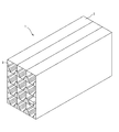
本実施形態の物品保管装置1は、架台部材2と、複数の物品移動装置6を有する。
架台部材2は、一種の棚であり、細長い形状の収容部3を複数列、複数段に設けたものである。
物品移動装置6は、架台部材2の各収容部3の中にあって、後記する様に各収容部3の中を走行する。
図9の様に収容物57は、パレット8に載せた状態で架台部材2に収容される。パレット8は公知であり、木製又は樹脂製である。
Hereinafter, embodiments of the present invention will be further described.
The
The
The
As shown in FIG. 9, the contained
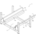
図2、図3の様に、各収容部3は、一対の走行ガイド部材10a、10bが一定の距離を空けて平行に設けられたものである。
As shown in FIGS. 2 and 3, in each
架台部材2では、2つの走行ガイド部材10a、10bが一組となって、支柱5に固定されている。
一対の走行ガイド部材10a、10bは、物品移動装置6が走行する空間を確保でき、且つその上にパレット8を載置することができる距離を空けて平行に設けられている。
In the
The pair of traveling
各走行ガイド部材10a、10bは、物品移動装置6が走行する走行路12と、パレット8を載置する載置部11が一体化された長尺部材である。
走行ガイド部材10a、10bは、上端面に水平面状の載置部11がある。また中間部には水平面状の走行路12がある。
走行ガイド部材10a、10bはパレット8の移動方向に長く延びている。
Each of the traveling
The traveling
The traveling
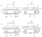
走行ガイド部材10a、10bの端部に注目すると、図3の様に位置決め用被検知部材17A,17Bと、方向検知用被検知部材18が設けられている(図3、図13)。被検知部材17A,17B,18は、いずれも反射部材である。
一方の位置決め用被検知部材17Aは、図3、図13の様に一方の走行ガイド部材10aに設けられいる。また他方の位置決め用被検知部材17Bは、図3、図13の様に他方の走行ガイド部材10bに設けられている。
二つの被検知部材17A,17Bは対向する位置にある。
方向検知用被検知部材18は、一方の走行ガイド部材10bだけに設けられている。
Focusing on the ends of the traveling
One of the positioning detected
The two detected
The direction detection detected
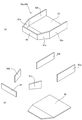
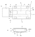
次に物品移動装置6について説明する。物品移動装置6は、図4、図5、図7の様に本体部(移動装置本体部)30と、保持部材31によって構成されている。また本体部30の下部にはフォークガイド部材55a,55bと、センサー保持部材7が設けられている。
本体部30は、図7の様に本体ケース33内に、昇降機構35、走行機構36、蓄電池37及び制御装置(図示せず)が内蔵されたものである。本体ケース33は、図5の様に、上面が開放され、平面形状が略正方形であって高さの低い箱である。
Next, the
As shown in FIG. 7, the
本体ケース33内に内蔵された昇降機構35は、保持部材31を昇降させるものである。昇降機構35は、図7の様に、4個のカム40a,40b,40c,40dと、昇降用モータ内蔵ローラ(昇降用回転部材)41及び両者を係合する動力伝導部によって構成されている。
The elevating
昇降用モータ内蔵ローラ41は、円筒形のローラ本体50内に図示しないモータと図示しない減速機が内蔵されたものであり、ローラ本体50の両端から固定軸が突出している。昇降用モータ内蔵ローラ41は、内部のモータを駆動することにより、外側の円筒形のローラ本体50が回転する。
The
昇降用モータ内蔵ローラ41を駆動させると、カム40a,40b,40c,40dが回動し、保持部材31が昇降する。
When the
走行機構36は、二組の走行機器によって構成されている。走行機器はいずれも走行用モータ内蔵ローラ(走行用回転部材)58と、走行輪56及び動力伝導ベルト63によって構成されている。
走行輪56は、回転軸が図示しない軸受けによって回転可能に支持されている。走行用モータ内蔵ローラ58を回転駆動させると、走行輪56が回転する。
The traveling
The traveling
その他、本体ケース33内には、蓄電池37及び制御装置が内蔵されている。
本実施形態では、昇降用モータ内蔵ローラ41(昇降用回転部材)と、走行用モータ内蔵ローラ(走行用回転部材)58及び蓄電池37は、本体部30の幅方向の中心軸CL上に並んでいる。
本実施形態では、昇降用モータ内蔵ローラ41(昇降用回転部材)と、走行用モータ内蔵ローラ(走行用回転部材)58及び蓄電池37は重く、これらの三者が、本体部30に内蔵される機器の重量の大半を占める。
In addition, a
In the present embodiment, the
In the present embodiment, the
本体ケース33の外周に目を移すと、図4、図5の様に本体ケース33の2辺に、軌道修正コロ32が2個ずつ設けられている。軌道修正コロ32は、回転軸が垂直姿勢となる様に設置されている。
Looking at the outer circumference of the
また本体ケース33の下面(本体部30の下部)には二組のフォークガイド部材55a,55bと、センサー保持部材7が設けられている。
フォークガイド部材55a,55bは、図10、図11の様にフォークリフト(運搬装置)100のフォーク101を誘導するものである。
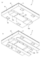
2個のフォークガイド部材55a,55bは、同じ形状であるから、代表して一方のフォークガイド部材55aについて説明する。フォークガイド部材55aは、鋼板で作られたものであり、平面形状は図5、図6、図8の様に変則六角形であるが対称形である。
フォークガイド部材55aは、本体ケース33の下面から垂下する縦壁60乃至62を有している。具体的には、フォークガイド部材55aは、図5、図6の様に、姿勢が異なる5枚の縦壁60、61a,61b,62a,62bと、底板65によって構成されている。即ちフォークガイド部材55aは、正面縦壁60と、2枚の傾斜縦壁61a,61bと、平行縦壁62a,62b及び底板65によって構成されている。
Further, two sets of
The
Since the two
The
図8の様に本体ケース33の四角の各辺を端辺70、71と側辺72、73とすると、正面縦壁60は、本体ケース33の一方の端辺70の近傍にあって、平面視した取り付け姿勢は、端辺70に対して略平行である。
図6の様に、正面縦壁60自体は、長方形の板である。
Assuming that each side of the square of the
As shown in FIG. 6, the front
傾斜縦壁61a,61bは、正面縦壁60の両端と連続し、平面視した姿勢は、端辺70、71及び側辺72、73に対して傾斜した姿勢となっている。本実施形態では、傾斜縦壁61a,61bは、本体部30の端辺70、71及び側辺72、73に対して45度の角度で傾斜している。
傾斜縦壁61a,61b自体は、図6の様に台形の板である。
The inclined
The inclined
図6の様に平行縦壁62a,62bは、傾斜縦壁61a,61bと連続し、平面視した姿勢は、本体部30の側辺72、73に対して略平行に延びている。
平行縦壁62a,62b自体は長方形の板である。平行縦壁62a,62bの高さは、正面縦壁60の高さに比べて高い。
As shown in FIG. 6, the parallel
The parallel
底板65は、前記した正面縦壁60と、傾斜縦壁61a,61b及び平行縦壁62a,62bによって囲まれる空間の底面を覆うものである。
The
図8の様に、平行縦壁62a,62b間の全幅wは、本体ケース33の全幅Wに対して4分の1から2分の1程度である。本実施形態では、平行縦壁62a,62b間の全幅wは、本体ケース33の全幅Wに対して3分の1程度である。
As shown in FIG. 8, the total width w between the parallel
フォークガイド部材55aの全高hは、平行縦壁62a,62bの高さによって決まる。図8の様に、フォークガイド部材55aの全高hは、本体ケース33の全幅Wに対して8分の1から20分の1程度であり、好ましくは、9分の1から15分の1であり、より好ましくは、10分の1から14分の1である。
この様に、フォークガイド部材55aの全高hは、本体ケース33の全幅Wに対して極めて低い。
ただし、フォークガイド部材55aの全高hは、フォークリフトのフォークの肉圧に比べると大きい。
The total height h of the
As described above, the total height h of the
However, the total height h of the
フォークガイド部材55aは、本体ケース33の下部であって、幅方向の中心(中心軸CLに沿った位置)にあり、正面縦壁60が本体ケース33の端辺70の近傍にあって、他の部分は、端辺70から奥側に向かって配置されている。
フォークガイド部材55aを概観すると、本体部(移動装置本体部)30の下部であって幅方向の中央部に設けられ、本体部30から奥側に向かって幅が広がり、さらの奥側が平行状態となって延びている。
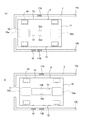
本実施形態では、本体ケース33の下面(本体部30の下部)には二組のフォークガイド部材55a,55bがあり、一方のフォークガイド部材55aは、端辺70側にあり、他方のフォークガイド部材55bは端辺71側にある。
The
Looking at the
In the present embodiment, there are two sets of
本実施形態では、二組のフォークガイド部材55a,55b同士の間には隙間があり、当該隙間に、センサー保持部材7が設けられている。
センサー保持部材7は、長方形の箱であり、本体ケース33の下側であって、本体ケース33の両側の側辺の近傍から垂下されている。センサー保持部材7の幅は、フォークガイド部材55a、55bの幅wよりも小さい。またセンサー保持部材7の高さは、フォークガイド部材55a、55bの高さhよりも低い。
そのためセンサー保持部材7は、二組のフォークガイド部材55a,55bの間であって、奥まった位置に配置されている。そのためフォークリフト100のフォーク101が当たりにくい。
In the present embodiment, there is a gap between the two sets of
The
Therefore, the
センサー保持部材7には、光電センサー等の近接センサーが取り付けられている。本実施形態では、反射型のセンサーであり、図示しない発光部材と受光部材を有している。センサーは、側面側の物を検知するセンサ−である。
本実施形態では、左右のセンサー保持面に取り付けられている近接センサーの数が異なっている。
即ち一方のセンサー保持面には図13の様に位置確認検知センサー52aだけが設けられている。
これに対して他方のセンサー保持面には図13の様に位置確認検知センサー52bと、方向検知センサー53が設けられている。
A proximity sensor such as a photoelectric sensor is attached to the
In this embodiment, the number of proximity sensors attached to the left and right sensor holding surfaces is different.
That is, only the position
On the other hand, the position
保持部材31は、本体ケース33よりも一回り大きい専有面積を有する部材であり、平面視が略正方形である。
保持部材31は、本体ケース33の上に載置されている。保持部材31は図示しないガイドを有し、本体ケース33に対して上下方向にのみ移動する。保持部材31の下面側に昇降機構35の4個のカム40a,40b,40c,40dが接し、4個のカム40a,40b,40c,40dによって保持部材31が支持されている。また保持部材31は、本体ケース33に対して上下方向に自由度を持ち、カム40a,40b,40c,40dの回動に伴って昇降する。
The holding
The holding
上記した物品移動装置6は、前記した様に架台部材2の各収容部3に一個ずつ配備されている。そして走行用モータ内蔵ローラ58を起動して各走行輪56を回転させると、物品移動装置6は、架台部材2の走行ガイド部材10a、10bで囲まれた細長い空間を直線移動する。
走行用モータ内蔵ローラ58は、正方向にも逆方向にも回転可能であるから、各走行輪56は、動力によって正方向及び逆方向に回転する。そのため物品移動装置6は、走行路12を正方向にも逆方向にも走行する。
As described above, the above-mentioned
Since the
また物品移動装置6の昇降機構35が降下した状態においては、図9(a)の様に保持部材31は、走行ガイド部材10a、10bの載置部11よりも下に沈む。従って走行ガイド部材10a、10bにパレット8が載置されていたとしても、物品移動装置6の保持部材31がパレット8に接することはない。そのためパレット8の底は、走行ガイド部材10a、10bの載置部11と接した状態を維持する。
Further, when the elevating
その一方で昇降機構35を上昇させると、図9(b)の様に保持部材31は、走行ガイド部材10a、10bの載置部11よりも上に上昇する。
従って、図9(b)の様に走行ガイド部材10a、10bの載置部11にパレット8が載置されていたならば、物品移動装置6の保持部材31によってパレット8が走行ガイド部材10a、10bからすくい上げられ、パレット8は、走行ガイド部材10a、10bの載置部11から離れる。
On the other hand, when the elevating
Therefore, if the
物品移動装置6は、フォークリフト(搬送装置)100に載置されて架台部材2の各収容部3に配置される。具体的には、図10、図11の様に物品移動装置6の本体部30の下部にフォークリフトのフォーク(爪)101を挿入し、フォーク101を上昇させて物品移動装置6を持ち上げ、架台部材2の端部から物品移動装置6を架台部材2の収容部3に挿入する。
ここで本実施形態で採用する物品移動装置6では、フォークガイド部材55a,55bが両端にあり、作業者は、フォークリフト100のフォーク(爪)を端辺70側から差し入れることもでき、端辺71側から差し入れることもできる。
The
Here, in the
またフォークガイド部材55a,55bは、ブロック状であって、本体部30の幅方向の中心にある。また本体部30の下部であって、本体部30の側辺72、73側は開放されており、なんらの障害物も無い。
そのためフォーク101は、本体部30の下部の位置において自由度が高く、動かしやすい。
また本実施形態の物品移動装置6では、図12(a)の様に物品移動装置6を床上においたとき、物品移動装置6のフォークガイド部材55a,55bの底面が床102に接し、物品移動装置6の各走行輪56は、床面を離れて中空に浮いた状態となるから、物品移動装置6がフォーク101で突かれたとしても、物品移動装置6は転がり移動しない。そのためフォーク101を差し入れやすい。
Further, the
Therefore, the
Further, in the
フォーク101は、物品移動装置6のいずれかの端辺70、71側から本体部30の下部に差し入れられるが、フォークガイド部材55a,55bの端部たる正面縦壁60は、フォークガイド部材55a,55bの全幅wに比べて幅が狭い。そのため二本のフォーク101の間に正面縦壁60を対向させやすい。
実際の作業は、正面縦壁60に二本のフォーク101の間を対向させ、且つ正面縦壁60の中心と二本のフォーク101の間の中心を一致させる。そしてこの状態でフォークリフトを前進させて二本のフォーク101の間にフォークガイド部材55a,55bを挟んだ状態でフォーク101を本体部30の下部に差し入れて行く。
The
In the actual work, the front
ここで仮に二本のフォーク101の中心と、正面縦壁60の中心が一致していなければ、フォーク101の先端は、フォークガイド部材55a,55bの傾斜縦壁61a,61bに当たる。そしてそのままフォークリフト100を前進させると、フォークガイド部材55a,55bの傾斜縦壁61a,61bに押されて物品移動装置6が姿勢を変え、フォーク101の伸び方向と、フォークガイド部材55a,55bの方向が一致し、フォーク101が本体部30の下部に滑り込んでゆく。この様にフォーク101が本体部30の下部に入り込み、フォーク101を上昇させることによって物品移動装置6が持ち上げられる。
Here, if the centers of the two
また本実施形態の物品移動装置6では、重量物がフォークガイド部材55a,55bの真上の位置に集中的に配置されている。
さらにフォークガイド部材55a,55bの全幅wは相当に大きい。
そのため物品移動装置6を水平な床102上に置くと、フォークガイド部材55a,55bの底の平坦部分が床面と接し、物品移動装置6は、図12(a)の様に本体部30が略水平姿勢となる姿勢で自立する。
また本実施形態の物品移動装置6は、フォークガイド部材55a,55bの全高hに比べて本体部30の幅Wが極端に広いから、図12(b)の様に物品移動装置6に外力を加えて強制的に傾斜姿勢としても、本体部30の両翼部分が床面と接し、それ以上に傾斜姿勢となることはない。
Further, in the
Further, the total width w of the
Therefore, when the
Further, in the
即ち物品移動装置6に外力を強制的に傾斜姿勢にすると、図12(b)の様に、フォークガイド部材55a,55bの下部の端部が支点Cとなって傾斜姿勢となり、本体部30の端部が設置点Dとなる。
この時の重心の位置Aは、設置点Dに対して支点Cよりも離れた位置にあり、重心を通る仮想垂線103は、設置点Dに対して支点Cよりも離れた位置を通過する。
そのため物品移動装置6には、支点Cを中心として、上昇側を降下させる方向にモーメントが作用する。そのため、強制力を解除すると、図12(c)の様に、物品移動装置6は、水平姿勢に復帰する。
That is, when the external force is forced into the tilted posture of the
The position A of the center of gravity at this time is located at a position farther from the fulcrum C with respect to the installation point D, and the virtual
Therefore, a moment acts on the
また本実施形態では、物品移動装置6の最大傾斜角度は僅かであり、保持部材31が傾斜姿勢となった際における傾斜方向の分力は、保持部材31とパレット8との間の最大摩擦力よりも小さい。そのため物品移動装置6が傾斜姿勢となってもパレット8は滑らず荷崩れしない。
Further, in the present embodiment, the maximum tilt angle of the
本実施形態で採用する物品移動装置6は、原則的に前後方向の区別はなく、端辺70側と端辺71側のいずれを前側(前進側 正方向側)とし、いずれを後側(後進側 逆方向側)としてもよい。
即ち本実施形態で採用する物品移動装置6では、端辺70側と端辺71側の形状及び機能は同一である。
In principle, the
That is, in the
本実施形態で採用する物品移動装置6は、各センサー52,53、被検知部材17A,17B,18等によって構成される検知手段と、制御装置にプログラムされた前後決定手段によって自動的に端辺70側を前とするか端辺71側を前とするかを判別することができる。
以下、走行方向の前後を決める前後決定手段の機能について説明する。
本実施形態の物品移動装置6では、前記した様に本体部30の底面にセンサー保持部材7があり、物品移動装置6の側辺73側には位置確認検知センサー52aだけが設けられ、側辺72側には位置確認検知センサー52bと、方向検知センサー53が設けられている。
The
Hereinafter, the function of the front / rear determining means for determining the front / rear in the traveling direction will be described.
In the
一方、走行ガイド部材10a、10bの端部近傍には位置決め用被検知部材17A,17Bが設けられている。ここで位置決め用被検知部材17A,17Bは、物品移動装置6が所定の基準位置にあるときに、物品移動装置6の位置確認検知センサー52a,52bが対向してこれを検知する位置に設けられている。
そのため一方フォークリフトによって物品移動装置6が架台部材2の収容部3に配置された状態のとき、手動あるいは自動によって物品移動装置6を少し移動させ、物品移動装置6が所定の基準位置にとまると位置確認検知センサー52a,52bが位置決め用被検知部材17A,17Bを検知する。
On the other hand, positioning detected
Therefore, on the other hand, when the
また本実施形態では、側辺73側だけに方向検知センサー53が設けられている。そのため、図12(a)の様に、物品移動装置6の端辺70側が収容部3の奥側に向いていたならば、方向検知センサー53が方向検知用被検知部材18を検知する。
そこで本実施形態では、位置確認検知センサー52a,52bと方向検知センサー53の3者が同時に被検知部材17A,17B,18を検知したことを条件として、物品移動装置6の端辺70側を前と認識し、端辺71側を後ろと認識する。そしてこの情報が制御装置の記憶手段に記憶される。
そしてそれ以降は、端辺70側が前進方向となる様に走行輪56が回転する。
Further, in the present embodiment, the
Therefore, in the present embodiment, on the condition that the position
After that, the traveling
一方、位置確認検知センサー52a,52bが同時に位置決め用被検知部材17A,17Bを検知しているものの、方向検知センサー53が方向検知用被検知部材18を検知できていない場合には、物品移動装置6の端辺71側を前と認識し、端辺70側を後ろと認識する。
On the other hand, if the position
センサー保持部材7に取り付けられるセンサーは、実施形態に限定されるものではなく、物品移動装置6の停止位置を確認するセンサー等であってもよい。
The sensor attached to the
保持部材31とパレット8との間の摩擦を増大させるために、保持部材31の表面に摩擦増大処理を施してもよい。また保持部材31の表面に凹凸を設ける等によってパレット8を保持部材31と係合させ、パレット8の移動を防止してもよい。
In order to increase the friction between the holding
1 物品保管装置
2 架台部材
6 物品移動装置
7 センサー保持部材
8 パレット
12 走行路
30 本体部(移動装置本体部)
31 保持部材
33 本体ケース
37 蓄電池
41 昇降用モータ内蔵ローラ(昇降用回転部材)
55a,55b フォークガイド部材
56 走行輪
58 走行用モータ内蔵ローラ(走行用回転部材)
60 正面縦壁
61a,61b 傾斜縦壁
62a,62b 平行縦壁
65 底板
100 フォークリフト
101 フォーク
C 支点
D 設置点
1
31 Holding
55a, 55b
60 Front
Claims (7)
移動装置本体部と、物品を保持する保持部材を有し、
前記移動装置本体部には動力によって回転する走行輪と、前記保持部材を昇降させる昇降機構があり、
載置部の下に配されて走行輪を回転することにより走行路を走行可能であり、保持部材を降下した際には保持部材が載置部の上端よりも下に沈み、保持部材を上昇した際には保持部材が載置部の上端よりも上に突出する物品移動装置において、
別途用意の運搬装置のフォークを誘導するフォークガイド部材を有し、
当該フォークガイド部材は、移動装置本体部の下部であって幅方向の中央部に設けられ、移動装置本体部の端部側から奥側に向かって幅が広がる部材であり、
物品移動装置を水平な床面に設置すると、フォークガイド部材の下部側が直接的又は間接的に床面に接して走行輪が床面を離れ、且つ物品移動装置は略水平姿勢を保ち、
物品移動装置に強制力を与えて最大限に傾斜させても強制力を排除すると略水平姿勢に復帰することを特徴とする物品移動装置。 An article moving device that is arranged on a gantry member having a traveling path and a mounting portion and travels on the traveling path to transport articles.
It has a moving device main body and a holding member for holding articles.
The moving device main body has a traveling wheel that is rotated by power and an elevating mechanism that raises and lowers the holding member.
It is possible to travel on the running path by rotating the traveling wheel arranged under the mounting portion, and when the holding member is lowered, the holding member sinks below the upper end of the mounting portion and the holding member rises. In the article moving device in which the holding member protrudes above the upper end of the mounting portion when the holding member is used.
It has a fork guide member that guides the fork of the separately prepared transport device.
The fork guide member is a member that is provided at the lower part of the moving device main body and is provided at the center in the width direction, and the width widens from the end side to the back side of the moving device main body.
When the article moving device is installed on a horizontal floor surface, the lower side of the fork guide member directly or indirectly contacts the floor surface, the traveling wheel leaves the floor surface, and the article moving device maintains a substantially horizontal posture.
An article moving device characterized in that even if a forced force is applied to the article moving device and the article is tilted to the maximum, the posture returns to a substantially horizontal posture when the forced force is removed.
最大傾斜姿勢の状態において、物品移動装置の重心を通る仮想垂線は、前記支点よりも接地点から離れた位置を通過することを特徴とする請求項1に記載の物品移動装置。 When a forcible force is applied to the article moving device to incline it, the article moving device is tilted with a part of the lower part as a fulcrum, and the part other than the fulcrum of the article moving device becomes a grounding point in contact with the floor surface and becomes the maximum tilted posture. , No further tilting is possible,
The article moving device according to claim 1, wherein the virtual vertical line passing through the center of gravity of the article moving device passes through a position farther from the grounding point than the fulcrum in the state of the maximum inclined posture.
フォークガイド部材は、略垂直に立設されたガイド壁を有し、
前記ガイド壁は、移動装置本体部の一方の端辺側にあって幅方向の中央側から脇方向に向かって傾斜する傾斜領域と、移動装置本体部の奥側にあって前記側辺に対して略平行に延びる平行領域を有し、
物品移動装置に強制力を与えて傾斜させると、一方の傾斜壁の下部を支点として物品移動装置が傾斜し、移動装置本体部の一部が床面に当接してそれ以上の傾斜が不能となることを特徴とする請求項1乃至3のいずれかに記載の物品移動装置。 The main body of the mobile device is substantially quadrangular and has a pair of ends and a pair of sides.
The fork guide member has a guide wall that is erected approximately vertically.
The guide wall is located on one end side of the mobile device main body and has an inclined region inclined from the central side in the width direction toward the side, and is located on the inner side of the mobile device main body and is relative to the side side. Has a parallel region extending substantially parallel to
When the article moving device is tilted by applying a forcible force, the article moving device is tilted with the lower part of one of the tilted walls as a fulcrum, and a part of the moving device main body abuts on the floor surface, making further tilting impossible. The article moving device according to any one of claims 1 to 3, wherein the article moving device is characterized by the above.
複数の物品を載置する架台部材と、請求項1乃至6のいずれかに記載の物品移動装置を有し、
架台部材は、走行路と、前記物品の移動方向にのび、その上に前記物品が載置される2列以上の載置部を有し、
物品移動装置は、載置部の下に配されていて走行輪を回転することにより走行路を走行可能であり、保持部材を降下した際には保持部材が載置部の上端よりも下に沈み、保持部材を上昇した際には保持部材が載置部の上端よりも上に突出し、
物品移動装置を前記物品の下に移動した後に保持部材を上昇させて保持部材で前記物品をすくい上げ、走行輪を回転させて物品移動装置を移動し、保持部材を降下させて前記物品を架台部材の他の位置に移動させることが可能であることを特徴とする物品保管装置。 In an article storage device capable of accommodating a plurality of articles and having a function of moving the articles.
It has a gantry member on which a plurality of articles are placed and an article moving device according to any one of claims 1 to 6.
The gantry member has a traveling path and two or more rows of mounting portions on which the article is placed, extending in the moving direction of the article.
The article moving device is arranged under the mounting portion and can travel on the traveling path by rotating the traveling wheel, and when the holding member is lowered, the holding member is below the upper end of the mounting portion. When it sinks and the holding member is raised, the holding member protrudes above the upper end of the mounting portion, and the holding member protrudes above the upper end.
After moving the article moving device under the article, the holding member is raised to scoop up the article with the holding member, the traveling wheel is rotated to move the article moving device, and the holding member is lowered to mount the article on the gantry member. An article storage device characterized in that it can be moved to another position.
Priority Applications (1)
| Application Number | Priority Date | Filing Date | Title |
|---|---|---|---|
| JP2018012880A JP6980193B2 (en) | 2018-01-29 | 2018-01-29 | Goods storage device and goods moving device |
Applications Claiming Priority (1)
| Application Number | Priority Date | Filing Date | Title |
|---|---|---|---|
| JP2018012880A JP6980193B2 (en) | 2018-01-29 | 2018-01-29 | Goods storage device and goods moving device |
Publications (3)
| Publication Number | Publication Date |
|---|---|
| JP2019131314A JP2019131314A (en) | 2019-08-08 |
| JP2019131314A5 JP2019131314A5 (en) | 2021-02-12 |
| JP6980193B2 true JP6980193B2 (en) | 2021-12-15 |
Family
ID=67547219
Family Applications (1)
| Application Number | Title | Priority Date | Filing Date |
|---|---|---|---|
| JP2018012880A Active JP6980193B2 (en) | 2018-01-29 | 2018-01-29 | Goods storage device and goods moving device |
Country Status (1)
| Country | Link |
|---|---|
| JP (1) | JP6980193B2 (en) |
Family Cites Families (7)
| Publication number | Priority date | Publication date | Assignee | Title |
|---|---|---|---|---|
| US2836384A (en) * | 1954-03-15 | 1958-05-27 | Haglind Lumber Company | Pallet with metal clad stringers |
| JPS4842257U (en) * | 1971-09-21 | 1973-05-30 | ||
| JPS49144631U (en) * | 1973-04-09 | 1974-12-13 | ||
| JPH0872875A (en) * | 1994-09-01 | 1996-03-19 | C C I Kk | Synthetic resin-made pallet |
| JP2006036289A (en) * | 2004-07-28 | 2006-02-09 | Toyota Industries Corp | Fork guide mechanism, pallet guide mechanism, and article transfer apparatus |
| KR101498945B1 (en) * | 2013-09-30 | 2015-03-05 | 주식회사동양강철 | Aluminium pallet |
| JP6892068B2 (en) * | 2016-01-18 | 2021-06-18 | 伊東電機株式会社 | Goods storage device and goods moving device |
-
2018
- 2018-01-29 JP JP2018012880A patent/JP6980193B2/en active Active
Also Published As
| Publication number | Publication date |
|---|---|
| JP2019131314A (en) | 2019-08-08 |
Similar Documents
| Publication | Publication Date | Title |
|---|---|---|
| JP6892068B2 (en) | Goods storage device and goods moving device | |
| JP5770110B2 (en) | Storage equipment, and especially warehouse racks and cargo handling equipment for this equipment | |
| KR101147569B1 (en) | Article transporting apparatus | |
| JP2022017470A (en) | Tire storage, removal, and inventory management system | |
| JP6980193B2 (en) | Goods storage device and goods moving device | |
| JP5765577B2 (en) | Stacker crane | |
| JP5348493B2 (en) | Lifting type article transport device | |
| JP5182565B2 (en) | Article conveying device | |
| US20220242678A1 (en) | Pallet Inspection Device | |
| JP2009113907A (en) | Article conveying device | |
| JP5267856B2 (en) | Stacker crane and article storage equipment | |
| JPH0515456Y2 (en) | ||
| JP5471261B2 (en) | Lifting type article transport device | |
| JP2009203028A (en) | Article transporting device | |
| KR102614292B1 (en) | a logistics robot for acceptance of non-standard freight | |
| JP2007217102A (en) | Automated storage and retrieval warehouse | |
| CN219468996U (en) | Workbin snatchs mechanism with workbin detection function that targets in place | |
| JPH09226911A (en) | Fork type stacker crain | |
| KR102654603B1 (en) | 4-way driving shuttle | |
| JP5487614B2 (en) | Automatic warehouse | |
| JP5305080B2 (en) | Goods storage equipment | |
| JP7322917B2 (en) | carrier | |
| JP4003321B2 (en) | Automatic warehouse crane | |
| JP3708068B2 (en) | Labor-saving outrigger device | |
| JP5240503B2 (en) | Goods storage equipment |
Legal Events
| Date | Code | Title | Description |
|---|---|---|---|
| A621 | Written request for application examination |
Free format text: JAPANESE INTERMEDIATE CODE: A621 Effective date: 20201223 |
|
| A521 | Written amendment |
Free format text: JAPANESE INTERMEDIATE CODE: A523 Effective date: 20201224 |
|
| TRDD | Decision of grant or rejection written | ||
| A01 | Written decision to grant a patent or to grant a registration (utility model) |
Free format text: JAPANESE INTERMEDIATE CODE: A01 Effective date: 20211028 |
|
| A977 | Report on retrieval |
Free format text: JAPANESE INTERMEDIATE CODE: A971007 Effective date: 20211028 |
|
| A61 | First payment of annual fees (during grant procedure) |
Free format text: JAPANESE INTERMEDIATE CODE: A61 Effective date: 20211105 |
|
| R150 | Certificate of patent or registration of utility model |
Ref document number: 6980193 Country of ref document: JP Free format text: JAPANESE INTERMEDIATE CODE: R150 |