JP6892068B2 - Goods storage device and goods moving device - Google Patents
Goods storage device and goods moving device Download PDFInfo
- Publication number
- JP6892068B2 JP6892068B2 JP2017006623A JP2017006623A JP6892068B2 JP 6892068 B2 JP6892068 B2 JP 6892068B2 JP 2017006623 A JP2017006623 A JP 2017006623A JP 2017006623 A JP2017006623 A JP 2017006623A JP 6892068 B2 JP6892068 B2 JP 6892068B2
- Authority
- JP
- Japan
- Prior art keywords
- article
- holding member
- moving device
- traveling
- article moving
- Prior art date
- Legal status (The legal status is an assumption and is not a legal conclusion. Google has not performed a legal analysis and makes no representation as to the accuracy of the status listed.)
- Active
Links
Images


Landscapes
- Warehouses Or Storage Devices (AREA)
Description
本発明は、倉庫等の物品保管装置に関するものであり、特にその内部で物品を移動することが可能な物品保管装置に関するものである。また本発明は、物品を載置する架台部材に配置され、物品を搬送する物品移動装置に関するものである。 The present invention relates to an article storage device such as a warehouse, and more particularly to an article storage device capable of moving articles within the article storage device. The present invention also relates to an article moving device that is arranged on a gantry member on which an article is placed and conveys an article.
大型の倉庫では、内部空間を有効に利用し、多くの物品を収容できる様に棚が設けられている場合が多い。旧来の大型倉庫では、所定の間隔をおいて棚を並べ、フォークリフト等の運搬装置によって物品を棚に配置していた。
近年では、倉庫内の空間をより有効に利用すべく、棚自体に物品を移動する機能を持たせた物品載置装置が倉庫内に設置される場合がある。
ここで物品を移動させる方策としては、特許文献1の様に棚内にコンベア装置を設置する構造と、特許文献2に開示された様な物品移動装置を走行させる構造がある。
In large warehouses, shelves are often provided so that the internal space can be used effectively and many items can be stored. In the old large warehouse, shelves were lined up at predetermined intervals, and goods were placed on the shelves by a transport device such as a forklift.
In recent years, in order to make more effective use of the space in the warehouse, an article placing device having a function of moving articles on the shelf itself may be installed in the warehouse.
Here, as a measure for moving the article, there are a structure in which the conveyor device is installed in the shelf as in
特許文献2に開示された物品移動装置は、走行輪を持った車体と、昇降可能な載置台を有し、自走する。
また棚側には走行レールが敷設されている。走行レールには走行輪が走行する走行路がある。そして走行路よりも高い位置に物品を載置する載置面がある。載置面には倉庫に収容する収容物を載せたパレットが載置されている。
特許文献2に開示された物品移動装置では、物品移動装置をパレットの下に移動し、載置台を上昇してパレットをすくい上げ、走行輪を回転して走行レール上を走行して物品を移動する。
The article moving device disclosed in
In addition, a running rail is laid on the shelf side. The traveling rail has a traveling path on which traveling wheels travel. And there is a mounting surface on which the article is placed at a position higher than the running path. On the mounting surface, a pallet containing the contents to be stored in the warehouse is placed.
In the article moving device disclosed in
また物品移動装置を備えた物品保管装置では、物品の衝突を防止するためや、物品同士の間隔を一定に保つことを目的として、物品移動装置に超音波センサ等の物体検知手段が設けられている。
特許文献2に開示された物品保管装置では、物品移動装置の車体部分に物体検知手段が取り付けられている。より具体的には、特許文献2に開示された物品保管装置では、第一の物体検知手段と、第二の物体検知手段を有し、これらはいずれも物品移動装置の車体部分に取り付けられている。
そして物品移動装置に物品を載置した状態で物品移動装置を走行させ、第一の物体検知手段が前方に既存のパレットを検知すると物品移動装置の走行速度を減速し、第二の物体検知手段が既存のパレットを検知すると物品移動装置の走行を停止する。
Further, in an article storage device equipped with an article moving device, an object detecting means such as an ultrasonic sensor is provided in the article moving device for the purpose of preventing collision of articles and keeping the distance between articles constant. There is.
In the article storage device disclosed in
Then, the article moving device is moved with the article placed on the article moving device, and when the first object detecting means detects an existing pallet in front, the traveling speed of the article moving device is reduced, and the second object detecting means is used. Stops the movement of the article moving device when it detects an existing pallet.
特許文献2に開示された物品保管装置では、物品移動装置の車体部分に取り付けられた物体検知手段によって、物品の衝突を回避すると共に物品同士の間隔を一定に保つ。
しかしながら、特許文献2に開示された物品保管装置は、物体検知手段が誤検知を起こす懸念があった。
即ち特許文献2に開示された物品移動装置では、物体検知手段は、物品移動装置の本体側に取り付けられている。
ここで特許文献2に開示された物品移動装置では、既存のパレットは、走行路よりも高い位置に設置された載置面に載置されている。
一方、物品移動装置の本体側は、載置面よりも下の位置にある走行路を走行する。そのため特許文献2に開示された物品移動装置では、物体検知手段の取り付け高さと、検出対象たるパレットの高さに落差がある。そのため物体検知手段は斜め下側から検出対象たるパレットを検知することとなり、超音波等の反射を正確に検知できない場合がある。
In the article storage device disclosed in
However, in the article storage device disclosed in
That is, in the article moving device disclosed in
Here, in the article moving device disclosed in
On the other hand, the main body side of the article moving device travels on a traveling path located below the mounting surface. Therefore, in the article moving device disclosed in
本発明は、従来技術の上記した問題点に注目し、物体検知手段の誤検知が少ない物品保管装置及び物品移動装置を提供することを課題とする。
また本発明は、いずれの端部が前であり、いずれが後ろであるかを確認する機能を有する物品移動装置を提供することを課題とする。
また本発明は、フォークリフト等の爪を入れやすい物品移動装置を提供することを課題とする。
また本発明は、前後の区別が無く使い勝手の良い物品移動装置を提供することを課題とする。
It is an object of the present invention to pay attention to the above-mentioned problems of the prior art and to provide an article storage device and an article moving device with less false detection of object detection means.
Another object of the present invention is to provide an article moving device having a function of confirming which end is the front and which is the back.
Another object of the present invention is to provide an article moving device such as a forklift that can easily insert a claw.
Another object of the present invention is to provide an article moving device that is easy to use and has no distinction between front and back.
上記した課題を解決するための本発明の第1の態様は、複数の物品を収容可能であると共に前記物品を移動させる機能を備えた物品保管装置において、複数の物品を載置する架台部材と、自走して前記物品を移動させる物品移動装置を有し、架台部材は、走行路と、前記物品の移動方向にのびその上に前記物品が載置される2列以上の載置部を有し、物品移動装置は、動力によって回転する走行輪と、物品を保持する保持部材と、当該保持部材を昇降させる昇降機構とを有し、物品移動装置は、載置部の間に配されていて走行輪を回転することにより走行路を走行可能であり、保持部材を降下した際には保持部材が載置部の上端よりも下に沈み、保持部材を上昇した際には保持部材が載置部の上端よりも上に突出し、物品移動装置を前記物品の下に移動した後に保持部材を上昇させて保持部材で前記物品をすくい上げ、走行輪を回転させて物品移動装置を移動し、保持部材を降下させて前記物品を架台部材の他の位置に移動させることが可能であり、載置部に載置された既存の物体の存在を検知する物体検知手段を有し、当該物体検知手段は昇降する部材に取り付けられていることを特徴とする物品保管装置である。 A first aspect of the present invention for solving the above-mentioned problems is an article storage device capable of accommodating a plurality of articles and having a function of moving the articles, and a pedestal member on which the plurality of articles are placed. The gantry member has an article moving device that runs on its own to move the article, and the gantry member has a traveling path and two or more rows of mounting portions on which the article is placed in the moving direction of the article. The article moving device has a traveling wheel that is rotated by power, a holding member that holds the article, and an elevating mechanism that raises and lowers the holding member, and the article moving device is arranged between the mounting portions. It is possible to travel on the traveling path by rotating the traveling wheel, and when the holding member is lowered, the holding member sinks below the upper end of the mounting portion, and when the holding member is raised, the holding member is moved. After projecting above the upper end of the mounting portion and moving the article moving device under the article, the holding member is raised to scoop up the article with the holding member, and the traveling wheel is rotated to move the article moving device. It is possible to lower the holding member to move the article to another position of the gantry member, and it has an object detecting means for detecting the existence of an existing object mounted on the mounting portion, and the object detecting The means is an article storage device characterized in that it is attached to a member that moves up and down.
本態様の物品保管装置では、物体検知手段は昇降する部材に取り付けられている。そのため物体検知手段の高さをパレット等の被検知物の高さに近づけることができる。望ましくは、物体検知手段の高さをパレット等の被検知物の一部と重ねる。
また物体検知手段の高さを下げることにより、物品移動装置を既設のパレット等の下に潜り込ませたり、既設のパレット等の下を通過させることができる。
In the article storage device of this embodiment, the object detection means is attached to a member that moves up and down. Therefore, the height of the object detection means can be made close to the height of the object to be detected such as a pallet. Desirably, the height of the object detection means overlaps with a part of the object to be detected such as a pallet.
Further, by lowering the height of the object detection means, the article moving device can be slipped under the existing pallet or the like or passed under the existing pallet or the like.
物体検知手段を上昇した状態で走行輪を走行させて物品移動装置を走行し、物体検知手段が物品の存在を検知した場合には物体検知手段を降下した状態で物品移動装置を物品の下に潜りこませることができることが望ましい。 The traveling wheel is moved with the object detecting means raised to travel on the article moving device, and when the object detecting means detects the presence of the article, the article moving device is placed under the article with the object detecting means lowered. It is desirable to be able to sneak in.
物体検知手段は前記保持部材に取り付けられていることが望ましい。 It is desirable that the object detection means is attached to the holding member.
保持部材は、物品をすくい上げるために昇降する機能を有している。そのため物体検知手段を取り付ける部材として好適である。 The holding member has a function of raising and lowering to scoop up an article. Therefore, it is suitable as a member for attaching the object detection means.
上記した各態様において、物品の長さを測定する長さ測定手段を有し、当該長さ測定手段は物品移動装置の上方に物品が存在するか否かを検知する存在検知手段を有し、物品移動装置を物品の下に潜りこませた状態で物品移動装置を走行させ、存在検知手段の検知状況と物品移動装置の走行距離によって物品の長さを測定することが望ましい。 In each of the above aspects, the length measuring means for measuring the length of the article is provided, and the length measuring means has the presence detecting means for detecting whether or not the article is present above the article moving device. It is desirable to run the article moving device with the article moving device submerged under the article and measure the length of the article based on the detection status of the presence detecting means and the mileage of the article moving device.
物品保管装置に収容される物品は、一定の大きさに限らない。例えば、パレットに収容物を載置して物品保管装置に保管する場合であっても、パレットの全長に長短がある場合がある。
そのため、全長の短いパレットが並んで配置されている様な場合であれば、前後のパレットの下に跨がった状態で物品移動装置が停止し、保持部材を上昇させてしまうと、前後のパレットの双方を下から突き上げてしまうこととなり、パレットを正しく上昇させることができない。
本態様はこの様な場合に対処するものであり、長さ測定手段で物品の長さを測定することができる。そのためパレットを股がない様な位置に物品移動装置を停止し、保持部材の所定の位置にパレット等の物品を載置することができる。
The articles contained in the article storage device are not limited to a certain size. For example, even when the contents are placed on the pallet and stored in the article storage device, the total length of the pallet may be long or short.
Therefore, in the case where pallets with a short overall length are arranged side by side, if the article moving device is stopped while straddling under the front and rear pallets and the holding member is raised, the front and rear Both sides of the pallet will be pushed up from below, and the pallet cannot be raised correctly.
This aspect deals with such a case, and the length of the article can be measured by the length measuring means. Therefore, the article moving device can be stopped at a position where the pallet does not have a crotch, and an article such as a pallet can be placed at a predetermined position of the holding member.
上記した各態様において、一対の検知センサーと被検知部材によって構成される方向検知手段を有し、前記物品移動装置に検知センサー又は被検知部材のいずれか一方があり、前記架台部材に検知センサー又は被検知部材の他方があり、前記一対の検知センサーと被検知部材の取り付け位置は、物品移動装置の一辺側が特定の方向に向いて架台部材の端部近傍にある場合に検知センサーが被検知部材を検知し、物品移動装置の前記一辺側が前記特定の方向とは逆に向いて架台部材の端部近傍にある場合に検知センサーが被検知部材を検知し得ない位置であり、走行方向の前後を決める前後決定手段を有し、検知センサーが被検知部材を検知した場合には、いずれか一方側が前進方向となる様に走行輪が回転し、検知センサーが被検知部材を検知しない場合には、他方側が前進方向となる様に走行輪が回転する構成を採用することが望ましい。 In each of the above aspects, the article moving device has either a detection sensor or a detection member, and the gantry member has a detection sensor or a detection sensor or a direction detection means composed of a pair of detection sensors and a member to be detected. There is the other side of the detected member, and the mounting position of the pair of detected sensors and the detected member is such that when one side of the article moving device faces a specific direction and is near the end of the gantry member, the detected sensor is the detected member. Is detected, and when the one side side of the article moving device faces in the opposite direction to the specific direction and is near the end of the gantry member, the detection sensor cannot detect the detected member, and is in front of and behind the traveling direction. When the detection sensor detects the detected member, the traveling wheel rotates so that one side is in the forward direction, and the detection sensor does not detect the detected member. It is desirable to adopt a configuration in which the traveling wheels rotate so that the other side is in the forward direction.
また上記した各態様において、架台部材の端部に物品移動装置の落下を防止するためのストッパーがあり、検知センサーと被検知部材を有し、前記物品移動装置に検知センサー又は被検知部材のいずれか一方があり、前記ストッパーに検知センサー又は被検知部材の他方があり、前記検知センサーと被検知部材の取り付け位置は、物品移動装置の一辺側が特定の方向に向いて架台部材の端部近傍にある場合に検知センサーが被検知部材を検知し、物品移動装置の前記一辺側が前記特定の方向とは逆に向いて架台部材の端部近傍にある場合に検知センサーが被検知部材を検知し得ない位置であり、走行方向の前後を決める前後決定手段を有し、検知センサーが被検知部材を検知した場合には、いずれか一方側が前進方向となる様に走行輪が回転し、検知センサーが被検知部材を検知しない場合には、他方側が前進方向となる様に走行輪が回転することが望ましい。 Further, in each of the above aspects, there is a stopper at the end of the gantry member to prevent the article moving device from falling, and the article moving device has a detection sensor and a detected member, and the article moving device is either a detection sensor or a detected member. There is one, the stopper has the detection sensor or the other of the detected member, and the mounting position of the detection sensor and the detected member is near the end of the gantry member with one side of the article moving device facing a specific direction. In some cases, the detection sensor may detect the member to be detected, and the detection sensor may detect the member to be detected when the one side of the article moving device faces in the opposite direction to the specific direction and is near the end of the gantry member. It is not in a position and has a front-back determining means for determining the front-back direction of the traveling direction. When the detection sensor detects a member to be detected, the traveling wheel rotates so that one side is in the forward direction, and the detection sensor moves When the member to be detected is not detected, it is desirable that the traveling wheel rotates so that the other side is in the forward direction.
また上記した各態様において、検知センサーと被検知部材を有し、物品移動装置の走行方向に対して両側の側面部分にそれぞれ検知センサー又は被検知部材が設けられており、前記検知センサーと被検知部材の取り付け位置は、物品移動装置の走行方向に沿った一辺側が特定の方向に向いて架台部材の端部近傍にある場合に一方の検知センサーだけが被検知部材を検知し、物品移動装置の前記一辺側が前記特定の方向とは逆に向いて架台部材の端部近傍にある場合は他方の検知センサーだけが被検知部材を検知する位置であり、走行方向の前後を決める前後決定手段を有し、一方の検知センサーが被検知部材を検知した場合には、いずれか一方側が前進方向となる様に走行輪が回転し、他方の検知センサーが被検知部材を検知した場合には他方側が前進方向となる様に走行輪が回転することが望ましい。 Further, in each of the above-described aspects, the detection sensor and the detected member are provided, and the detection sensor or the detected member is provided on each of the side surface portions on both sides with respect to the traveling direction of the article moving device. As for the mounting position of the article, when one side along the traveling direction of the article moving device faces a specific direction and is near the end of the gantry member, only one detection sensor detects the member to be detected, and the article moving device is attached. When the one side is facing away from the specific direction and is near the end of the gantry member, only the other detection sensor is at the position where the detected member is detected, and there is a front-back determining means for determining the front-back of the traveling direction. However, when one of the detection sensors detects the member to be detected, the traveling wheel rotates so that one side is in the forward direction, and when the other detection sensor detects the member to be detected, the other side moves forward. It is desirable that the traveling wheels rotate in the direction.
上記した検知センサーと被検知部材を有する態様は、物品移動装置のいずれの端部が前であり、いずれが後ろであるかを確認する機能を有するものである。
以下説明する。
一般に架台部材は、多段構造であり、3階建てや4階建ての構造となっている。
また物品移動装置は、フォークリフトやクレーン等で各段の走行路等に設置される。そして外部に設置された制御装置から無線又は有線による信号を受けて走行輪のモータが回転し、走行路を走行する。
ここで物品移動装置は前進移動と後進移動を行うことが必要であるから、走行路等には定められた向きに設置されなければならない。
即ち、モータを正回転させて前進し、モータを逆回転させると後退する向きに物品移動装置を置く必要がある。
しかしながら、前記した様にフォークリフトやクレーン等を使用して物品移動装置を各段の走行路等に設置するので、設置の際に物品移動装置の向きを確認しにくい。そのため本来前方に向けるべき面を後方に向けて設置してしまう場合もある。
この様に設置すると、外部に設置された制御装置から走行輪のモータを回転する指令を受けたとき、本来向かうべき方向とは逆方向に物品移動装置が暴走してしまうこととなる。
この問題を解決するための方策として、物品移動装置を走行路に設置した際に、物品移動装置の前後を決める構成を採用することが推奨される。
上記した態様は、この方策の具体例であり、一対の検知センサーと被検知部材によって構成される方向検知手段を有している。本態様では、一対の検知センサーと被検知部材の取り付け位置は、物品移動装置の一辺側が特定の方向に向いて架台部材の端部近傍にある場合に検知センサーが被検知部材を検知し、物品移動装置の前記一辺側が前記特定の方向とは逆に向いて架台部材の端部近傍にある場合に検知センサーが被検知部材を検知し得ない位置である。そのため検知センサーの検知状況によって物品移動装置が置かれた向きが判る。
本態様の物品保管装置は、さらに前後決定手段を有し、検知センサーが被検知部材を検知した場合には、いずれか一方側が前進方向となる様に走行輪が回転し、検知センサーが被検知部材を検知しない場合には、他方側が前進方向となる様に走行輪が回転する。
本態様の物品保管装置によると、物品移動装置の前後関係が自動的に決められる。
The aspect of having the detection sensor and the member to be detected described above has a function of confirming which end of the article moving device is the front and which is the back.
This will be described below.
Generally, the gantry member has a multi-stage structure, and has a three-story or four-story structure.
In addition, the article moving device is installed on the traveling path of each stage by a forklift, a crane, or the like. Then, the motor of the traveling wheel rotates by receiving a wireless or wired signal from the control device installed outside, and travels on the traveling path.
Here, since it is necessary for the article moving device to move forward and backward, it must be installed in a predetermined direction on a traveling path or the like.
That is, it is necessary to place the article moving device in a direction in which the motor is rotated forward to move forward and the motor is rotated backward to move backward.
However, as described above, since the article moving device is installed on the traveling path of each stage by using a forklift, a crane, or the like, it is difficult to confirm the orientation of the article moving device at the time of installation. Therefore, there are cases where the surface that should originally face forward is installed facing backward.
When installed in this way, when a command to rotate the motor of the traveling wheel is received from the control device installed outside, the article moving device runs out of control in the direction opposite to the direction in which it should originally go.
As a measure for solving this problem, it is recommended to adopt a configuration that determines the front and back of the article moving device when the article moving device is installed on the traveling path.
The above-described aspect is a specific example of this measure, and has a direction detecting means composed of a pair of detection sensors and a member to be detected. In this embodiment, the mounting position of the pair of detection sensors and the member to be detected is such that the detection sensor detects the member to be detected when one side of the article moving device faces a specific direction and is near the end of the gantry member. This is a position where the detection sensor cannot detect the detected member when the one side side of the moving device faces in the direction opposite to the specific direction and is near the end of the gantry member. Therefore, the direction in which the article moving device is placed can be known from the detection status of the detection sensor.
The article storage device of this embodiment further has a front-rear determination means, and when the detection sensor detects a detected member, the traveling wheel rotates so that either one side is in the forward direction, and the detection sensor detects the detected member. If the member is not detected, the traveling wheel rotates so that the other side is in the forward direction.
According to the article storage device of this aspect, the context of the article moving device is automatically determined.
記憶手段を有し、前後決定手段によって決められた前後関係が記憶手段に記憶されることが望ましい。 It is desirable to have a storage means and to store the context determined by the context-determining means in the storage means.
方向検知手段を有する構成においては、少なくとも一対の位置確認検知センサーと位置確認用被検知部材によって構成される位置確認手段を有し、当該位置確認検知センサーは前記方向検知手段を構成する検知センサーとは別のセンサーであり、位置確認検知センサーが位置確認用被検知部材を検知したことを条件として前後決定手段が前後方向を決めることが望ましい。 In the configuration having the direction detection means, the position confirmation means including at least a pair of position confirmation detection sensors and the position confirmation detected member is provided, and the position confirmation detection sensor is a detection sensor constituting the direction detection means. Is another sensor, and it is desirable that the front-rear determination means determines the front-rear direction on condition that the position confirmation detection sensor detects the position-confirmed member to be detected.
本態様によると、方向検知手段を構成する検知センサーの誤検知が防止される。 According to this aspect, erroneous detection of the detection sensor constituting the direction detecting means is prevented.
上記した各態様において、物品の姿勢を修正する修正ガイド部材があり、当該ガイド部材は載置部の外側又はその近傍に設けられ、載置部に載置した物品の姿勢が正規の状態から外れている状態で物品移動装置を走行させた場合に前記ガイド部材が物品に接触して物品の姿勢が正規の状態に修正することが望ましい。 In each of the above aspects, there is a correction guide member that corrects the posture of the article, and the guide member is provided outside or near the mounting portion, and the posture of the article placed on the mounting portion deviates from the normal state. It is desirable that the guide member comes into contact with the article and the posture of the article is corrected to a normal state when the article moving device is moved in the state of being in contact with the article.
本態様によると、物品移動装置に載置している物品の姿勢を自動的に修正することができる。 According to this aspect, the posture of the article placed on the article moving device can be automatically corrected.
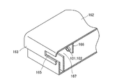
上記した各態様において、物品移動装置は別途用意の搬送装置によって搬送可能であり、前記搬送装置は爪を有し、物品移動装置の本体部に前記爪が挿入される爪収納部材が設けられており、爪収納部材の一部は物品移動装置の本体部が構成する平面から外側にはみ出ていることが望ましい。 In each of the above aspects, the article moving device can be conveyed by a separately prepared transport device, the transport device has a claw, and a claw storage member into which the claw is inserted is provided in the main body of the article moving device. It is desirable that a part of the claw storage member protrudes outward from the plane formed by the main body of the article moving device.
本態様によると、フォークリフト等で物品移動装置を搬送する際、爪収納部材の位置を確認し易い。 According to this aspect, it is easy to confirm the position of the claw storage member when transporting the article moving device by a forklift or the like.
上部に物体が存在するか否かを検知する上部確認センサーを有し、当該上部確認センサーが、爪収納部材の本体部が構成する平面から外側にはみ出たはみ出し部に設けられていることが望ましい。 It is desirable to have an upper confirmation sensor that detects whether or not an object is present on the upper part, and that the upper confirmation sensor is provided on a protruding portion that protrudes outward from the plane formed by the main body of the claw storage member. ..
上部確認センサーの用途は自由であり、例えば物品移動装置上の物の移動を検知させることができる。また上部確認センサーによって物品の長さを測定してもよい。 The upper confirmation sensor can be used for any purpose, for example, it can detect the movement of an object on an article moving device. Further, the length of the article may be measured by the upper confirmation sensor.
走行輪を回転させる走行機構を有し、当該走行機構は、走行用モータ内蔵ローラを有し、当該走行用モータ内蔵ローラはローラ本体内にモータが内蔵されてローラ本体が回転するものであり、前記ローラ本体の両端近傍に動力伝動用係合部材が装着または形成されており、前記走行用モータ内蔵ローラは物品移動装置の走行方向に対して直交する方向に配置され、前記走行輪は動力伝動用係合部材から他の動力伝動部材を介して、あるいは動力伝動用係合部材から直接動力伝動を受けて回転し、昇降機構は、昇降用モータ内蔵ローラとカムを有し、当該昇降用モータ内蔵ローラはローラ本体内にモータが内蔵されてローラ本体が回転するものであり、前記ローラ本体の両端近傍に動力伝動用係合部材が装着または形成されており、前記昇降用モータ内蔵ローラは物品移動装置の走行方向に対して直交する方向に配置され、前記カムは動力伝動用係合部材から他の動力伝動部材を介して、あるいは動力伝動用係合部材から直接動力伝動を受けて回動することが望ましい。 It has a traveling mechanism that rotates the traveling wheels, the traveling mechanism has a roller with a built-in traveling motor, and the roller with a built-in traveling motor has a motor built in the roller body and the roller body rotates. Power transmission engaging members are mounted or formed near both ends of the roller body, the traveling motor built-in roller is arranged in a direction orthogonal to the traveling direction of the article moving device, and the traveling wheel is powered. The elevating mechanism has a roller with a built-in elevating motor and a cam, and rotates by receiving power transmission from the engaging member via another power transmission member or directly from the engaging member for power transmission. The built-in roller has a motor built in the roller body to rotate the roller body, and power transmission engaging members are mounted or formed in the vicinity of both ends of the roller body. Arranged in a direction orthogonal to the traveling direction of the moving device, the cam rotates by receiving power transmission from the power transmission engaging member via another power transmission member or directly from the power transmission engagement member. It is desirable to do.
本態様によると、幅の異なる物品移動装置を製造する際における部品の互換性が高い。 According to this aspect, the compatibility of parts is high when manufacturing article moving devices having different widths.
前後方向を確認することができる物品移動装置を備えた態様は、複数の物品を収容可能であると共に前記物品を移動させる機能を備えた物品保管装置において、複数の物品を載置する架台部材と、自走して前記物品を移動させる物品移動装置を有し、架台部材は、走行路と、前記物品の移動方向にのびその上に前記物品が載置される2列以上の載置部を有し、物品移動装置は、動力によって回転する走行輪と、物品を保持する保持部材と、当該保持部材を昇降させる昇降機構とを有し、物品移動装置は、載置部の間に配されていて走行輪を回転することにより走行路を走行可能であり、保持部材を降下した際には保持部材が載置部の上端よりも下に沈み、保持部材を上昇した際には保持部材が載置部の上端よりも上に突出し、物品移動装置を前記物品の下に移動した後に保持部材を上昇させて保持部材で前記物品をすくい上げ、走行輪を回転させて物品移動装置を移動し、保持部材を降下させて前記物品を架台部材の他の位置に移動させることが可能であり、一対の検知センサーと被検知部材によって構成される方向検知手段を有し、前記物品移動装置に検知センサー又は被検知部材のいずれか一方があり、前記架台部材に検知センサー又は被検知部材の他方があり、前記一対の検知センサーと被検知部材の取り付け位置は、物品移動装置の一辺側が特定の方向に向いて架台部材の端部近傍にある場合に検知センサーが被検知部材を検知し、物品移動装置の前記一辺側が前記特定の方向とは逆に向いて架台部材の端部近傍にある場合に検知センサーが被検知部材を検知し得ない位置であり、走行方向の前後を決める前後決定手段を有し、検知センサーが被検知部材を検知した場合には、いずれか一方側が前進方向となる様に走行輪が回転し、検知センサーが被検知部材を検知しない場合には、他方側が前進方向となる様に走行輪が回転することを特徴とする物品保管装置である。 An embodiment provided with an article moving device capable of confirming the front-rear direction is an article storage device capable of accommodating a plurality of articles and having a function of moving the articles, and a pedestal member on which a plurality of articles are placed. The gantry member has an article moving device that runs on its own to move the article, and the gantry member has a traveling path and two or more rows of mounting portions on which the article is placed in the moving direction of the article. The article moving device has a traveling wheel that is rotated by power, a holding member that holds the article, and an elevating mechanism that raises and lowers the holding member, and the article moving device is arranged between the mounting portions. It is possible to travel on the traveling path by rotating the traveling wheel, and when the holding member is lowered, the holding member sinks below the upper end of the mounting portion, and when the holding member is raised, the holding member is moved. After projecting above the upper end of the mounting portion and moving the article moving device under the article, the holding member is raised to scoop up the article with the holding member, and the traveling wheel is rotated to move the article moving device. It is possible to lower the holding member to move the article to another position of the gantry member, and it has a direction detecting means composed of a pair of detection sensors and a member to be detected, and the article moving device has a detection sensor. Alternatively, there is one of the members to be detected, the gantry member has the detection sensor or the other member to be detected, and the attachment position of the pair of detection sensors and the member to be detected is such that one side of the article moving device is in a specific direction. The detection sensor detects the member to be detected when facing and near the end of the gantry member, and detects when the one side side of the article moving device faces in the opposite direction to the specific direction and is near the end of the gantry member. It is a position where the sensor cannot detect the member to be detected, has a front-rear determination means for determining the front-back direction in the traveling direction, and when the detection sensor detects the member to be detected, one side is in the forward direction. This is an article storage device characterized in that when the traveling wheel rotates and the detection sensor does not detect the member to be detected, the traveling wheel rotates so that the other side is in the forward direction.
フォークリフト等の爪を入れやすい物品移動装置として望ましい態様は、複数の物品を収容可能であると共に前記物品を移動させる機能を備えた物品保管装置において、複数の物品を載置する架台部材と、自走して前記物品を移動させる物品移動装置を有し、架台部材は、走行路と、前記物品の移動方向にのびその上に前記物品が載置される2列以上の載置部を有し、物品移動装置は、動力によって回転する走行輪と、物品を保持する保持部材と、当該保持部材を昇降させる昇降機構とを有し、物品移動装置は、載置部の間に配されていて走行輪を回転することにより走行路を走行可能であり、保持部材を降下した際には保持部材が載置部の上端よりも下に沈み、保持部材を上昇した際には保持部材が載置部の上端よりも上に突出し、物品移動装置を前記物品の下に移動した後に保持部材を上昇させて保持部材で前記物品をすくい上げ、走行輪を回転させて物品移動装置を移動し、保持部材を降下させて前記物品を架台部材の他の位置に移動させることが可能であり、前記物品移動装置は別途用意の搬送装置によって搬送可能であり、前記搬送装置は爪を有し、物品移動装置の本体部に前記爪が挿入される爪収納部材が設けられており、爪収納部材の一部は物品移動装置の本体部が構成する平面から外側にはみ出てたみ出し部があり、上部に物体が存在するか否かを検知する上部確認センサーを有し、当該上部確認センサーが、爪収納部材の前記はみ出し部に設けられていることを特徴とする物品保管装置である。 A desirable embodiment of an article moving device such as a fork lift that can easily insert a claw is an article storage device capable of accommodating a plurality of articles and having a function of moving the articles, and a pedestal member on which a plurality of articles are placed and a self-supporting member. It has an article moving device that runs to move the article, and the gantry member has a traveling path and two or more rows of mounting portions on which the article extends in the moving direction of the article. The article moving device has a traveling wheel that is rotated by power, a holding member that holds the article, and an elevating mechanism that raises and lowers the holding member, and the article moving device is arranged between the mounting portions. It is possible to travel on the traveling path by rotating the traveling wheel, and when the holding member is lowered, the holding member sinks below the upper end of the mounting portion, and when the holding member is raised, the holding member is placed. Protruding above the upper end of the portion, after moving the article moving device under the article, the holding member is raised to scoop up the article with the holding member, and the traveling wheel is rotated to move the article moving device to move the holding member. Can be lowered to move the article to another position of the gantry member, the article moving device can be transported by a separately prepared transport device, the transport device has a claw, and the article moving device has a claw. A claw storage member into which the claw is inserted is provided in the main body portion of the article, and a part of the claw storage member has a protruding portion protruding outward from the plane formed by the main body portion of the article moving device, and has a protruding portion at the upper part. It is an article storage device having an upper confirmation sensor for detecting whether or not an object exists, and the upper confirmation sensor is provided at the protruding portion of the claw storage member.
望ましい物品移動装置の態様は、走行路と、直線状にのびる2列以上の載置部を有する架台部材に配され、前記走行路を走行して物品を搬送する物品移動装置において、動力によって回転する走行輪と、物品を保持する保持部材と、当該保持部材を昇降させる昇降機構とを有し、物品移動装置は、載置部の間に配されていて走行輪を回転することにより走行路を走行可能であり、保持部材を降下した際には保持部材が載置部の上端よりも下に沈み、保持部材を上昇した際には保持部材が載置部の上端よりも上に突出し、物品移動装置を前記物品の下に移動した後に保持部材を上昇させて保持部材で前記物品をすくい上げ、走行輪を回転させて物品移動装置を移動し、保持部材を降下させて前記物品を架台部材の他の位置に移動させることが可能であり、載置部に載置された既存の物体の存在を検知する物体検知手段を有し、当該物体検知手段は昇降する部材に取り付けられていることを特徴とする物品移動装置である。 A desirable mode of the article moving device is that the article moving device is arranged on a traveling path and a pedestal member having two or more rows of mounting portions extending in a straight line, and is rotated by power in the article moving device that travels on the traveling path and conveys articles. It has a traveling wheel, a holding member for holding the article, and an elevating mechanism for raising and lowering the holding member. The article moving device is arranged between the mounting portions and rotates the traveling wheel to rotate the traveling path. When the holding member is lowered, the holding member sinks below the upper end of the mounting portion, and when the holding member is raised, the holding member protrudes above the upper end of the mounting portion. After moving the article moving device under the article, the holding member is raised to scoop up the article with the holding member, the traveling wheel is rotated to move the article moving device, and the holding member is lowered to mount the article on the gantry member. It can be moved to another position, has an object detecting means for detecting the presence of an existing object placed on the mounting part, and the object detecting means is attached to a member that moves up and down. It is an article moving device characterized by.
もう一つの物品移動装置の態様は、走行路と、直線状にのびる2列以上の載置部を有する架台部材に配され、前記走行路を走行して物品を搬送する物品移動装置において、動力によって回転する走行輪と、物品を保持する保持部材と、当該保持部材を昇降させる昇降機構とを有し、物品移動装置は、載置部の間に配されていて走行輪を回転することにより走行路を走行可能であり、保持部材を降下した際には保持部材が載置部の上端よりも下に沈み、保持部材を上昇した際には保持部材が載置部の上端よりも上に突出し、前記物品をすくい上げ、走行輪を回転させて物品移動装置を移動し、保持部材を降下させて前記物品を架台部材の他の位置に移動させることが可能であり、前記物品移動装置は別途用意の搬送装置によって搬送可能であり、前記搬送装置は爪を有し、物品移動装置の本体部に前記爪が挿入される爪収納部材が設けられており、爪収納部材の一部は物品移動装置の本体部が構成する平面から外側にはみ出てたみ出し部があり、上部に物体が存在するか否かを検知する上部確認センサーを有し、当該上部確認センサーが、爪収納部材の前記はみ出し部に設けられていることを特徴とする物品移動装置である。 Another aspect of the article moving device is that the article moving device is arranged on a traveling path and a pedestal member having two or more rows of mounting portions extending in a straight line, and travels on the traveling path to convey articles. It has a traveling wheel that rotates by means of a traveling wheel, a holding member that holds the article, and an elevating mechanism that raises and lowers the holding member. The article moving device is arranged between the mounting portions and rotates the traveling wheel. It is possible to travel on the running path, and when the holding member is lowered, the holding member sinks below the upper end of the mounting portion, and when the holding member is raised, the holding member is above the upper end of the mounting portion. It is possible to project, scoop up the article, rotate the traveling wheel to move the article moving device, lower the holding member to move the article to another position of the gantry member, and the article moving device is separate. It can be transported by a prepared transport device, the transport device has a claw, and a claw storage member into which the claw is inserted is provided in the main body of the article moving device, and a part of the claw storage member moves the article. There is a protruding part that protrudes outward from the plane formed by the main body of the device, and it has an upper confirmation sensor that detects whether or not an object exists on the upper part, and the upper confirmation sensor is the above-mentioned nail storage member. It is an article moving device characterized by being provided in a protruding portion.
もう一つの態様は、複数の物品を収容可能であると共に前記物品を移動させる機能を備えた物品保管装置において、複数の物品を載置する架台部材と、自走して前記物品を移動させる物品移動装置を有し、架台部材は、走行路と、前記物品の移動方向にのびその上に前記物品が載置される2列以上の載置部を有し、物品移動装置は、動力によって正方向及び逆方向に回転する走行輪と、物品を保持する保持部材と、当該保持部材を昇降させる昇降機構とを有し、物品移動装置は、載置部の間に配されていて走行輪を回転することにより走行路を正方向及び逆方向に走行可能であり、保持部材を降下した際には保持部材が載置部の上端よりも下に沈み、保持部材を上昇した際には保持部材が載置部の上端よりも上に突出し、物品移動装置を前記物品の下に移動した後に保持部材を上昇させて保持部材で前記物品をすくい上げ、走行輪を回転させて物品移動装置を移動し、保持部材を降下させて前記物品を架台部材の他の位置に移動させることが可能であり、載置部に載置された既存の物体の存在を検知する物体検知手段が物品移動装置の正方向側と逆方向側の双方に設けられていることを特徴とする物品保管装置である。 In another aspect, in an article storage device capable of accommodating a plurality of articles and having a function of moving the articles, a pedestal member on which the plurality of articles are placed and an article that self-propells to move the articles. It has a moving device, and the gantry member has a traveling path and two or more rows of mounting portions on which the article is placed extending in the moving direction of the article, and the article moving device is positive by power. It has a traveling wheel that rotates in the direction and the opposite direction, a holding member that holds the article, and an elevating mechanism that raises and lowers the holding member. By rotating, the traveling path can be traveled in the forward direction and the reverse direction. When the holding member is lowered, the holding member sinks below the upper end of the mounting portion, and when the holding member is raised, the holding member is lowered. Projects above the upper end of the mounting portion, moves the article moving device under the article, then raises the holding member to scoop up the article with the holding member, and rotates the traveling wheel to move the article moving device. , The holding member can be lowered to move the article to another position of the gantry member, and the object detecting means for detecting the existence of the existing object mounted on the mounting portion is the positive of the article moving device. It is an article storage device characterized in that it is provided on both the directional side and the opposite direction side.
本態様の物品保管装置で採用する物品移動装置は、正方向側と逆方向側の双方に物体検知手段があるから、正方向側を前側として使用してもよく、逆方向側を前側として使用してもよい。そのため本態様の物品保管装置で採用する物品移動装置は、前後の区別が無く使い勝手が良い。 Since the article moving device used in the article storage device of this embodiment has object detection means on both the forward side and the reverse direction side, the forward side may be used as the front side, and the reverse side may be used as the front side. You may. Therefore, the article moving device used in the article storage device of this embodiment is easy to use because there is no distinction between front and back.
上記した態様において、物品移動装置は蓄電池を搭載し、当該蓄電池に給電するコネクタが、2か所以上に設けられていることが望ましい。 In the above aspect, it is desirable that the article moving device is equipped with a storage battery and that the connector for supplying power to the storage battery is provided at two or more places.
もう一つの態様は、複数の物品を収容可能であると共に前記物品を移動させる機能を備えた物品保管装置において、複数の物品を載置する架台部材と、自走して前記物品を移動させる物品移動装置を有し、架台部材は、走行路と、前記物品の移動方向にのびその上に前記物品が載置される2列以上の載置部を有し、物品移動装置は、動力によって回転する走行輪と、物品を保持する保持部材と、当該保持部材を昇降させる昇降機構とを有し、物品移動装置は、載置部の間に配されていて走行輪を回転することにより走行路を走行可能であり、保持部材を降下した際には保持部材が載置部の上端よりも下に沈み、保持部材を上昇した際には保持部材が載置部の上端よりも上に突出し、物品移動装置を前記物品の下に移動した後に保持部材を上昇させて保持部材で前記物品をすくい上げ、走行輪を回転させて物品移動装置を移動し、保持部材を降下させて前記物品を架台部材の他の位置に移動させることが可能であり、物品移動装置よりも上であって保持部材の上部領域を物品移動装置の走行方向側に外れた位置に物体が存在するか否かを検知する上部確認センサーを有することを特徴とする物品保管装置である。 In another aspect, in an article storage device capable of accommodating a plurality of articles and having a function of moving the articles, a pedestal member on which the plurality of articles are placed and an article that self-propells to move the articles. It has a moving device, and the gantry member has a traveling path and two or more rows of mounting portions on which the article is placed extending in the moving direction of the article, and the article moving device is rotated by power. It has a traveling wheel, a holding member for holding the article, and an elevating mechanism for raising and lowering the holding member. The article moving device is arranged between the mounting portions, and the traveling path is rotated by rotating the traveling wheel. When the holding member is lowered, the holding member sinks below the upper end of the mounting portion, and when the holding member is raised, the holding member protrudes above the upper end of the mounting portion. After moving the article moving device under the article, the holding member is raised to scoop up the article with the holding member, the traveling wheel is rotated to move the article moving device, and the holding member is lowered to mount the article on the gantry member. It is possible to move to another position, and it is possible to detect whether or not an object exists at a position above the article moving device and deviating from the upper region of the holding member in the traveling direction side of the article moving device. It is an article storage device characterized by having an upper confirmation sensor.
もう一つの態様は、複数の物品を収容可能であると共に前記物品を移動させる機能を備えた物品保管装置において、複数の物品を載置する架台部材と、自走して前記物品を移動させる物品移動装置を有し、架台部材は、走行路と、前記物品の移動方向にのびその上に前記物品が載置される2列以上の載置部を有し、物品移動装置は、動力によって回転する走行輪と、物品を保持する保持部材と、当該保持部材を昇降させる昇降機構とを有し、物品移動装置は、載置部の間に配されていて走行輪を回転することにより走行路を走行可能であり、保持部材を降下した際には保持部材が載置部の上端よりも下に沈み、保持部材を上昇した際には保持部材が載置部の上端よりも上に突出し、物品移動装置を前記物品の下に移動した後に保持部材を上昇させて保持部材で前記物品をすくい上げ、走行輪を回転させて物品移動装置を移動し、保持部材を降下させて前記物品を架台部材の他の位置に移動させることが可能であり、保持部材を上昇・降下させるカムを有し、前記カムと走行輪は相対回転可能であって、共通の軸線回りを回動することを特徴とする物品保管装置である。 In another aspect, in an article storage device capable of accommodating a plurality of articles and having a function of moving the articles, a pedestal member on which the plurality of articles are placed and an article that self-propells to move the articles. It has a moving device, and the gantry member has a traveling path and two or more rows of mounting portions on which the article is placed extending in the moving direction of the article, and the article moving device is rotated by power. It has a traveling wheel, a holding member for holding the article, and an elevating mechanism for raising and lowering the holding member. The article moving device is arranged between the mounting portions, and the traveling path is rotated by rotating the traveling wheel. When the holding member is lowered, the holding member sinks below the upper end of the mounting portion, and when the holding member is raised, the holding member protrudes above the upper end of the mounting portion. After moving the article moving device under the article, the holding member is raised to scoop up the article with the holding member, the traveling wheel is rotated to move the article moving device, and the holding member is lowered to mount the article on the gantry member. It has a cam that can be moved to another position and raises and lowers the holding member, and the cam and the traveling wheel are relatively rotatable and rotate around a common axis. It is an article storage device.
本態様によると、物品保管装置を小型化することができる。 According to this aspect, the article storage device can be miniaturized.
本発明の物品保管装置は、載置部に載置された既存の物体の存在を検知する物体検知手段を有する物品移動装置を有する。本発明の物品保管装置は、物体検知手段の誤検知が少ない。
また本発明の物品移動装置は、フォークリフト等の爪を入れやすい。
また本発明の物品移動装置は、前後の区別が無く使い勝手が良い。
The article storage device of the present invention has an article moving device having an object detecting means for detecting the presence of an existing object mounted on a mounting portion. The article storage device of the present invention has few false detections of the object detection means.
Further, the article moving device of the present invention can easily insert a claw such as a forklift.
Further, the article moving device of the present invention is easy to use because there is no distinction between front and back.
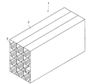
本実施形態の物品保管装置1は、架台部材2と、複数の物品移動装置6を有する。
架台部材2は、一種の棚であり、細長い形状の収容部3を3列4段に設けたものである。
物品移動装置6は、架台部材2の各収容部3の中にあって、後記する様に各収容部3の中を走行する。
収容物57は、パレット8に載せた状態で架台部材2に収容される。
The
The
The
The
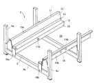
図2、図3の様に、各収容部3は、一対の走行ガイド部材10a、10bが一定の距離を空けて平行に設けられたものである。図2に示す様に、架台部材2は、複数の直立する支柱4aと、水平姿勢で支柱4aに固定された支持梁4bとで構成された構造物である。
As shown in FIGS. 2 and 3, in each
架台部材2では、2つの走行ガイド部材10a、10bが一組となって、支柱4aに固定されている。
一対の走行ガイド部材10a、10bは、物品移動装置6が走行する空間28を確保でき、且つその上にパレット8を載置することができる距離を空けて平行に設けられている。従って走行ガイド部材10a、10bの間隔は、物品移動装置6の幅よりも広く、パレット8の全長よりも短い。
In the
The pair of traveling
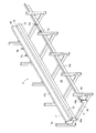
各走行ガイド部材10a、10bは、物品移動装置6が走行する走行路12と、パレット8を載置する載置部11が一体化された長尺部材である。
走行ガイド部材10a、10bは、具体的には金属板を曲げ加工して作られたものである。各走行ガイド部材10a、10bの外郭形状は図3の様であり、上端と中間部に水平部がある。
即ち走行ガイド部材10a、10bは、上端面に水平面状の載置部11がある。また中間部には水平面状の走行路12がある。そして上端面の載置部11と中間部の走行路12との間に傾斜壁部13と上部垂直壁部14とがある。また走行路12は下部垂直壁15に繋がっている。
収容部3の収容空間28は、2本の走行ガイド部材10a、10bによって構成されている。
走行ガイド部材10a、10bはパレット8の移動方向に長く延びている。
Each of the traveling
Specifically, the traveling
That is, the traveling
The
The traveling
走行ガイド部材10a、10bの端部に注目すると、図3の様にストッパ16a,16bが設けられている。ストッパ16a,16bは、物品移動装置6の脱落を防止するための防護壁であり、走行路12の端部にあって垂直姿勢の壁である。
Focusing on the ends of the traveling
また走行ガイド部材10a、10bの端部近傍に、位置決め用被検知部材17A,17Bと、方向検知用被検知部材18が設けられている(図3、図12)。被検知部材17A,17B,18は、いずれも反射部材である。
一方の位置決め用被検知部材17Aは、図3、図12の様に一方の走行ガイド部材10aに設けられいる。また他方の位置決め用被検知部材17Bは、図3、図12の様に他方の走行ガイド部材10bに設けられいる。
二つの被検知部材17A,17Bは対向する位置にある。即ち二つの被検知部材17A,17Bは、ストッパ16a,16bから等しい距離にある。
方向検知用被検知部材18は、一方の走行ガイド部材10bだけに設けられている。方向検知用被検知部材18は、ストッパ16bと被検知部材17Bの間である。
Further, positioning detected
One of the positioning detected
The two
The direction detection detected
走行ガイド部材10a、10bは、架台部材2の全長に渡る長さを有しているが、図2、図18の様にその中途部分に修正ガイド部材5a,5b,5c,5dが設置されている。具体的には走行ガイド部材10aに修正ガイド部材5a,5bが設置され、走行ガイド部材10bに修正ガイド部材5c,5dが設置されている。走行ガイド部材10aに設けられた修正ガイド部材5a,5bと、走行ガイド部材10bに設けられた修正ガイド部材5c,5dは対向する位置にある。
修正ガイド部材5a,5b,5c,5dは、走行ガイド部材10a、10bの外側にあり、軸を垂直にした姿勢で配置されている。修正ガイド部材5a,5b,5c,5dの高さ方向の位置は、走行ガイド部材10a、10bの載置部11の少し上に相当する高さである。
即ち修正ガイド部材5a,5b,5c,5dの配置位置は、走行ガイド部材10a、10bの幅方向(物品移動装置6が走行する空間28の幅方向)には、走行ガイド部材10a、10bの外側にあり、高さ方向には載置部11の少し上の位置である。
The traveling
The
That is, the arrangement positions of the
次に物品移動装置6について説明する。物品移動装置6は、図4、図5、図6の様に本体部30と、保持部材31によって構成されている。また本体部30の下部には爪収納部材55a,b,c,dと、本体側センサー保持部材7,9及びコネクタ保持部材130a,130bが設けられている。保持部材31には昇降側センサー保持部材26a,26bが設けられている。
本体部30は、図7の様に本体ケース33内に、昇降機構35、走行機構36、蓄電池37及び制御装置38が内蔵されたものである。本体ケース33は、図7の様に、上面が開放され、平面形状が略正方形であって高さの低い箱である。
Next, the
As shown in FIG. 7, the
本体ケース33内に内蔵された昇降機構35は、保持部材31を昇降させる昇降機構を構成するものである。昇降機構35は、図8の様に、4個のカム40a,40b,40c,40dと、昇降用モータ内蔵ローラ41(MDR)及び両者を係合する動力伝導部によって構成されている。
図8に示す様に、カム40a,40b,40c,40dは、インボリュート曲線を描く輪郭を有する板カムである。カム40a,40b,40c,40dの外郭には保持部材31が当接する。
カム40a,40b,40c,40dは二組に分かれ、図7の様に本体ケース33の長辺近傍に配されている。
カム40a,40b,40c,40dは、回転軸が図示しない軸受けによって回転可能に支持されている。また回転軸には歯付きプーリ42が設けられている。
The elevating
As shown in FIG. 8, the
The
The
昇降用モータ内蔵ローラ41は、円筒形のローラ本体50内に図示しないモータと図示しない減速機が内蔵されたものであり、ローラ本体50の両端から固定軸が突出している。昇降用モータ内蔵ローラ41は、モータ22を駆動することにより、外側の円筒形のローラ本体50が回転する。
実際の昇降用モータ内蔵ローラ41は、モータと減速機が一体化されたモータユニット21が、ローラ本体50内に内蔵されたものである。モータユニット21は互換性のあるものであり、長さの異なるローラ本体50に同一のモータユニット21を適用して昇降用モータ内蔵ローラ41を製造することができる。
本実施形態では、ローラ本体50の外周に動力伝動用係合部材として歯付きプーリ43が4個装着されている。歯付きプーリ43は、ローラ本体50の両端に2個ずつ設けられている。
The
In the
In the present embodiment, four
昇降用モータ内蔵ローラ41は、カム40a,40b,40c,40dによって挟まれた領域にある。そして昇降用モータ内蔵ローラ41の4個の歯付きプーリ43と、カム40a,40b,40c,40dの歯付きプーリ42の両者にそれぞれ歯付きベルト45が係合している。
昇降用モータ内蔵ローラ41の取り付け姿勢は、物品移動装置6の走行方向に対して直交する方向である。
The
The mounting posture of the
昇降用モータ内蔵ローラ41を駆動させると、ローラ本体50の外周に設けられた4個の歯付きプーリ43が回転し、当該回転が歯付きベルト45を介してカム40a,40b,40c,40d側の歯付きプーリ42に伝動され、カム40a,40b,40c,40dが回動する。
前記した様にカム40a,40b,40c,40dは保持部材31と接しており、カム40a,40b,40c,40dが回動することにより、保持部材31が昇降する。
なおいずれかのカム40a,40b,40c,40dの近傍には図示しないリミットスイッチが設置されている。このリミットスイッチによってカム40a,40b,40c,40dが特定の回転姿勢まで移動したことが検出される。即ち、特定の回転姿勢とは、保持部材31を上限まで押し上げる姿勢と、保持部材31を下限まで下げる姿勢である。
そしてカム40a,40b,40c,40dがこの姿勢に回動したことをリミットスイッチが検出すると、昇降用モータ内蔵ローラ41を停止させ、保持部材31の昇降移動を停止させることができる。
When the
As described above, the
A limit switch (not shown) is installed in the vicinity of any of the
When the limit switch detects that the
走行機構36は、図10の様に、二組の走行機器46によって構成されている。走行機器46はいずれも走行用モータ内蔵ローラ60と、走行輪61,62及び歯付きベルト63によって構成されている。
走行用モータ内蔵ローラ60は、円筒形のローラ本体66内にモータ22と減速機23が内蔵されたものであり、ローラ本体66の一端から固定軸67が突出している。走行用モータ内蔵ローラ60は、モータ22を駆動することにより、外側の円筒形のローラ本体66が回転する。
As shown in FIG. 10, the traveling
The traveling motor built-in
なお本実施形態で採用する走行用モータ内蔵ローラ60に内蔵するモータ22は、ホール素子を内蔵するブラシレスモータである。本実施形態で採用する走行用モータ内蔵ローラ60は内蔵するモータ22のホール素子が発生するパルスを図示しないカウンタでカウントすることができ、モータの回転数を検知することができる。
走行用モータ内蔵ローラ60についてもモータ22と減速機23が一体化されたモータユニット24が、ローラ本体60内に内蔵されたものである。モータユニット24についても互換性のあるものであり、長さの異なるローラ本体60に同一のモータユニット24を適用して走行用モータ内蔵ローラ60を製造することができる。
The
As for the
本実施形態では、走行用モータ内蔵ローラ60のローラ本体66の外周に動力伝動用係合部材として歯付きプーリ47が2個装着されている。
歯付きプーリ47は、ローラ本体60の両端に1個ずつ設けられている。
走行用モータ内蔵ローラ60の取り付け姿勢は、物品移動装置6の走行方向に対して直交する方向である。
走行輪61,62は、回転軸が図示しない軸受けによって回転可能に支持されている。また回転軸には歯付きプーリ48が取り付けられている。
そして走行用モータ内蔵ローラ60の歯付きプーリ47と、走行輪61,62側の歯付きプーリ48の両者に歯付きベルト63が係合している。
In the present embodiment, two
One
The mounting posture of the
The traveling
The
従って走行用モータ内蔵ローラ60を回転駆動させると、その回転力が歯付きプーリ47、歯付きプーリ47を介して歯付きプーリ48に伝動され、走行輪61,62が回転する。
Therefore, when the
その他、本体ケース33内には、蓄電池37及び制御装置38が内蔵されている。蓄電池37は、公知のリチウム電池等である。蓄電池37は前記した昇降用モータ内蔵ローラ41,及び走行用モータ内蔵ローラ60に電力を供給するものである。制御装置38についても蓄電池37の電力の供給を受けて動作する。
また蓄電池37を充電するための給電コネクタ131a,131bが本体ケース33の対向する短辺側側壁に設けられたコネクタ保持部材130a,130bに設けられている。
In addition, a
Further,
制御装置38は、無線通信を行う受信機を内蔵している。また制御装置38には、後記する一連の動作を実行するためのプログラムが格納されている。即ち、後記する移載動作、順送り動作、搬入動作、前詰め動作、搬出動作及び階移行動作を自動的に実行する基本動作プログラム25が格納されている。制御装置38には、物品移動装置6の前後を決定するための前後決定プログラム26と、前後決定手段プログラムによって決められた前後関係を記憶する記憶手段27が内蔵されている。
The
本体ケース33の外周に目を移すと、本体ケース33の2辺に、軌道修正コロ72が2個ずつ設けられている。軌道修正コロ72は、回転軸が垂直姿勢となる様に設置されている。
Looking at the outer circumference of the
本体ケース33の一対の短辺側側壁には、コネクタ保持部材130a,130bが一個ずつ設けられている。
コネクタ保持部材130a,130bには、前記した給電コネクタ131a,131bの他、非常停止ボタン132a,132bが設けられている。
One
In addition to the
また本体ケース33の下面(本体部30の下部)には爪収納部材55a,b,c,dと、本体側センサー保持部材7,9(図6)が設けられている。
爪収納部材55a,b,c,dは、フォークリフトの爪(図示せず)を挿入するための空間を形成するものであり、図6の様に断面形状が溝状の部材である。爪収納部材55a,b,c,dの全長は、本体ケース33の全長の2分の1未満である。
爪収納部材55a,b,c,dは2個で一組の部材であり、爪収納部材55a,55bの組と、爪収納部材55c,55dの組に分かれている。
説明の便宜上、図4,5,6の様に物品移動装置6の走行方向をA側、B側と称することとすれば、爪収納部材55a,55bはB側の組となり、爪収納部材55c,55dはA側の組となる。
Further, on the lower surface of the main body case 33 (lower part of the main body portion 30),
The
The
For convenience of explanation, if the traveling directions of the
各組の爪収納部材55a,b,c,dは、いずれも間隔を開け、物品移動装置6の走行方向に沿った方向に取り付けられている。なお本実施形態では、爪収納部材55a,b,c,dは、本体ケース33の下面に溶接されており、取り外すことはできない。
The
本体側センサー保持部材7,9は板状であり、本体ケース33の下側であって、本体ケース33の両側の側辺の近傍から垂下されている。
説明の便宜上、図4,5,6の様に物品移動装置6の走行方向に直行する方向をC側、D側と称することとすれば、本体側センサー保持部材7は物品移動装置6のC側に取り付けられており、本体側センサー保持部材9は物品移動装置6のD側に取り付けられている。いずれの本体側センサー保持部材7,9も、本体ケース33の長手方向(A−B)方向には、本体ケース33の中心近傍にある。
本体側センサー保持部材7,9の姿勢は、その表面が外側に面する姿勢である。
The main body side
For convenience of explanation, if the directions perpendicular to the traveling direction of the
The posture of the
本体側センサー保持部材7,9には、光電センサー等の近接センサーが取り付けられている。本実施形態では、反射型のセンサーであり、図示しない発光部材と受光部材を有している。
本実施形態では、左右の本体側センサー保持部材7,9に取り付けられている近接センサーの数が異なっている。
即ちC側の本体側センサー保持部材7には図4,5,6,12の様に位置確認検知センサー52aだけが設けられている。
これに対してD側の本体側センサー保持部材9には図4, 5,6,図12の様に位置確認検知センサー52bと、方向検知センサー53が設けられている。
左右の本体側センサー保持部材7,9に取り付けられた位置確認検知センサー52a,52bは、いずれも本体ケース33の長手方向(A−B)方向には、本体ケース33の中心にある。
D側の本体側センサー保持部材9に設けられた方向検知センサー53は、位置確認検知センサー52bよりもB方向側にある。本体側センサー保持部材9に設けられた位置確認検知センサー52bと、方向検知センサー53との間の距離は、一方の走行ガイド部材10bだけに設けられた位置決め用被検知部材17Bと方向検知用被検知部材18との間の距離と等しい。
Proximity sensors such as photoelectric sensors are attached to the
In this embodiment, the number of proximity sensors attached to the left and right main body side
That is, only the position
On the other hand, the main body side
The position
The
保持部材31は、本体ケース33よりも一回り大きい専有面積を有する部材であり、平面視が略正方形である。
保持部材31は、本体ケース33の上に載置されている。保持部材31は図示しないガイドを有し、本体ケース33に対して上下方向にのみ移動する。保持部材31の下面側に昇降機構35の4個のカム40a,40b,40c,40dが接し、4個のカム40a,40b,40c,40dによって保持部材31が支持されている。また保持部材31は、本体ケース33に対して上下方向に自由度を持ち、カム40a,40b,40c,40dの回動に伴って昇降する。
図4、図9(a)は保持部材31が降下した状態であり、図5、図9(b)は保持部材31が上昇した状態である。
The holding
The holding
4 and 9 (a) show a state in which the holding
保持部材31の走行方向側の両端(A側端部とB側端部)であって幅方向の中心には、切り欠き部100a,100bがある。そして当該切り欠き部100a,100bに昇降側センサー保持部材26a,26bが装着されている。
昇降側センサー保持部材26a,26bは同一の形状、構造である。昇降側センサー保持部材26a,26bには、それぞれ物体検知手段101,102が設けられている。
物体検知手段101,102は、例えば超音波センサーやレーザーセンサーであり、何らかの物体が一定の距離に近づいたことを検知するセンサーである。
The elevating side
The object detection means 101 and 102 are, for example, an ultrasonic sensor or a laser sensor, and are sensors that detect that some object approaches a certain distance.
二つの物体検知手段101,102は、検出距離が異なり、一方の物体検知手段101は極近くに物体が近づいたことを検知するものである。もう一つの物体検知手段102は、やや離れた位置の物体を検知する。
また保持部材31の上面であって、走行方向側の両端(A側端部とB側端部)にもセンサー103a,103bが設けられている。
センサー103a,103bは、パレット8の全長を測定するための反射型の光電センサーである。センサー(長さ測定手段)103a,103bは保持部材31の上方に物品が存在するか否かを検知する存在検知手段である。
The two
Further,
The
上記した物品移動装置6は、前記した様に架台部材2の各収容部3に一個ずつ配備されている。即ち物品移動装置6は、各収容部3に一個ずつある。より具体的に説明すると、物品移動装置6は、架台部材2の走行ガイド部材10a、10b同士で挟まれた空間28内に設置され、物品移動装置6の各走行輪61,62が走行路12の上面に載せられている。
物品移動装置6の各走行輪61,62は、走行路12と接している。
そのため走行用モータ内蔵ローラ60を起動して各走行輪61,62を回転させると、物品移動装置6は、架台部材2の走行ガイド部材10a、10bで囲まれた細長い空間28を直線移動する。また何らかの理由で、物品移動装置6が曲がった方向に移動しようとすると、物品移動装置6の本体ケース33の外側に設置された軌道修正コロ72(図4)が走行ガイド部材10a、10bの上部垂直壁部14に当たって走行方向を直線方向に修正する。
走行用モータ内蔵ローラ60は、正方向にも逆方向にも回転可能であるから、各走行輪61,62は、動力によって正方向及び逆方向に回転する。そのため物品移動装置6は、走行路12を正方向にも逆方向にも走行する。
なお走行用モータ内蔵ローラ60の正方向・逆方向は相対的なものに過ぎず、右回転を正方向とするか左回転を正方向とするかは任意である。同様に物品移動装置6の走行方向の正逆についても相対的にものに過ぎない。
As described above, the above-mentioned
The traveling
Therefore, when the traveling motor built-in
Since the
The forward and reverse directions of the traveling motor built-in
また物品移動装置6の昇降機構35が降下した状態においては、図9(a)の様に保持部材31は、走行ガイド部材10a、10bの載置部11よりも下に沈む。従って走行ガイド部材10a、10bにパレット8が載置されていたとしても、物品移動装置6の保持部材31がパレット8に接することはない。そのためパレット8の底は、走行ガイド部材10a、10bの載置部11と接した状態を維持する。
Further, when the elevating
その一方で昇降機構35を上昇させると、図9(b)の様に保持部材31は、走行ガイド部材10a、10bの載置部11よりも上に上昇する。
従って、図9(b)の様に走行ガイド部材10a、10bの載置部11にパレット8が載置されていたならば、物品移動装置6の保持部材31によってパレット8が走行ガイド部材10a、10bからすくい上げられ、パレット8は、走行ガイド部材10a、10bの載置部11から離れる。
On the other hand, when the elevating
Therefore, if the
物品移動装置6は、3種類の単独動作を実施することができる。単独動作の一つは降下動作であり、昇降用モータ内蔵ローラ41を回転させて昇降機構35を降下させ、保持部材31を走行ガイド部材10a、10bの載置部11よりも下に沈めることができる。
二つ目の単独動作は走行動作であり、走行用モータ内蔵ローラ60を起動して走行輪61,62を回転させることができる。
三つ目の単独動作は上昇動作であり、昇降用モータ内蔵ローラ41を逆回転させて昇降機構35を上昇させ、保持部材31を走行ガイド部材10の載置部11よりも上に突出させることができる。
また物品移動装置6は、前記した3種類の単独動作を連続して実行する移載動作を自動的に行うことができる。移載動作は、物品移動装置6の基本動作であり、降下動作と、走行動作と、上昇動作と、走行動作と、降下動作をこの順で行うものである。
降下動作で保持部材31を下ろした状態で走行させ、所定の位置で上昇動作を行ってパレット8をすくいあげ、パレット8を持ち上げたままで走行動作を実施してパレット8を移動し、降下動作を実施してパレット8を下ろすことができる。
The
The second independent operation is a traveling operation, in which the traveling motor built-in
The third independent operation is an ascending operation, in which the elevating motor built-in
Further, the
The holding
本実施形態の物品保管装置1では、前記した様に架台部材2の各収容部3に物品移動装置6が一個ずつ配備されている。
物品移動装置6は、図示しないフォークリフトに載置されて架台部材2の各収容部3に配置される。具体的には、物品移動装置6の下部に設けられた爪収納部材55a,b,c,dにフォークリフトの爪を挿入し、爪を上昇させて物品移動装置6を持ち上げ、架台部材2の端部から物品移動装置6を架台部材2の収容部3に挿入する。
ここで本実施形態で採用する物品移動装置6は、爪収納部材55a,b,c,dを4個有し、これが2個を一組として走行方向をA側、B側に取り付けられている。
そのため作業者は、フォークリフトの爪をA側から差し入れることもでき、B側から差し入れることもできる。
In the
The
Here, the
Therefore, the operator can insert the forklift claw from the A side or the B side.
本実施形態で採用する物品移動装置6は、原則的に前後方向の区別はなく、A側とB側のいずれを前側(前進側 正方向側)とし、いずれを後側(後進側 逆方向側)としてもよい。
即ち本実施形態で採用する物品移動装置6では、A側とB側の側面(短側側面)の形状及び機能は同一である。
具体的には、保持部材31のA側(正方向側)には昇降側センサー保持部材26aがあり、B側(逆方向側)には昇降側センサー保持部材26bがある。昇降側センサー保持部材26a,26bの形状や取り付けられた物体検知手段101,102は同じものである。
また昇降側センサー保持部材26a26a,26bは、取り付け位置や高さについても同じである。
In principle, the
That is, in the
Specifically, the holding
Further, the elevating side sensor holding members 26a26a and 26b have the same mounting position and height.
本体部30のA側にはコネクタ保持部材130aがあり、B側にはコネクタ保持部材1130bがある。コネクタ保持部材130a,130bの形状や取り付けられた給電コネクタ131a,131bと非常停止ボタン132a,132bは同じものである。
またコネクタ保持部材130a,130bは、取り付け位置や高さについても同じである。
There is a
Further, the
そして本実施形態で採用する物品移動装置6は、各センサー52,53、被検知部材17A,17B,18等によって構成される方向検知手段と、制御装置38にプログラムされた前後決定手段によって自動的にA側を前とするかB側を前とするかを判別することができ、その結果が制御装置38の記憶手段27に記憶される。
以下、走行方向の前後を決める前後決定手段の機能について説明する。
本実施形態の物品移動装置6では、前記した様に側面に本体側センサー保持部材7,9があり、物品移動装置6のC側に取り付けられた本体側センサー保持部材7には位置確認検知センサー52aだけが設けられ、D側の本体側センサー保持部材9には図4, 5,6,図12の様に位置確認検知センサー52bと、方向検知センサー53が設けられている。
The
Hereinafter, the function of the front-rear determining means for determining the front-back in the traveling direction will be described.
In the
一方、走行ガイド部材10a、10bの端部近傍には位置決め用被検知部材17A,17Bが設けられている。ここで位置決め用被検知部材17A,17Bは、物品移動装置6が所定の基準位置にあるときに、物品移動装置6の位置確認検知センサー52a,52bが対向してこれを検知する位置に設けられている。
そのため一方フォークリフトによって物品移動装置6が架台部材2の収容部3に配置された状態のとき、手動あるいは自動によって物品移動装置6を少し移動させ、物品移動装置6が所定の基準位置にとまると位置確認検知センサー52a,52bが位置決め用被検知部材17A,17Bを検知する。
On the other hand, positioning detected
Therefore, on the other hand, when the
また本実施形態では、D側の本体側センサー保持部材9だけに方向検知センサー53が設けられている。そして本体側センサー保持部材9に設けられた位置確認検知センサー52bと、方向検知センサー53との間の距離は、一方の走行ガイド部材10bだけに設けられた位置決め用被検知部材17Bと方向検知用被検知部材18との間の距離と等しい。そのため、図12(a)の様に、物品移動装置6のA側が収容部3の奥側に向いていたならば、方向検知センサー53が方向検知用被検知部材18を検知する。
そこで本実施形態では、位置確認検知センサー52a,52bと方向検知センサー53の3者が同時に被検知部材17A,17B,18を検知したことを条件として、物品移動装置6のA側を前と認識し、B側を後ろと認識する。そしてこの情報が制御装置38の記憶手段27に記憶される。
そしてそれ以降は、A側が前進方向となる様に走行輪61,62が回転する。
Further, in the present embodiment, the
Therefore, in the present embodiment, the A side of the
After that, the traveling
一方、位置確認検知センサー52a,52bが同時に位置決め用被検知部材17A,17Bを検知しているものの、方向検知センサー53が方向検知用被検知部材18を検知できていない場合には、物品移動装置6のB側を前と認識し、A側を後ろと認識する。
即ち図12(b)の様に、物品移動装置6のB側が収容部3の奥側に向いていたならば、方向検知センサー53は方向検知用被検知部材18を検知することができない。
そこで本実施形態では、位置確認検知センサー52a,52bが位置決め用被検知部材17A,17Bを検知し、方向検知センサー53が方向検知用被検知部材18を検知していないことを条件として、物品移動装置6のB側を前と認識し、A側を後ろと認識する。そしてこの情報が制御装置38の記憶手段27に記憶される。
そしてそれ以降は、B側が前進方向となる様に走行輪が回転する。
On the other hand, if the position
That is, as shown in FIG. 12B, if the B side of the
Therefore, in the present embodiment, the article is moved on the condition that the position
After that, the traveling wheels rotate so that the B side is in the forward direction.
次に、本実施形態の物品保管装置1の一連の動作について図14、図15、図16を参照しつつ説明する。
なお図14、図15、図16は、理解を容易にするために、物品移動装置6の動作を誇張して図示している。即ち図14、図15、図16では、保持部材31が大きく昇降するが、実際の保持部材31の昇降ストロークは小さい。即ち保持部材31を上昇した際には、保持部材31のA側端面またはB側端面の一部が、走行ガイド部材10a、10bの載置部11よりも少しだけ上に上がるに過ぎない。
Next, a series of operations of the
Note that FIGS. 14, 15, and 16 exaggerate the operation of the
本実施形態では、図示しないフォークリフト、クレーン、エレベータ等によって収容物57が載置されたパレット8aが、図14(a)の様に架台部材2の細長い形状の収容部3の始端部に載置される。
なお以下の説明は、先に他のパレット8bが収容部3に収容されている状態を想定している。
先行して収容されているパレット8bには収容物57が載置されている。先行して収容されているパレット8bは、図15の様に細長い形状の収容部3の奥にある。
パレット8a,8bは公知のパレットであり、天板120と底板121の間に梁122,123,124が設けられたものである。各梁122,123,124の間には、フォークリフトの爪を挿入する空間125があるが、中間部の梁123の部分は中実であり、開口は無い。
In the present embodiment, the
The following description assumes a state in which another
The
The
本実施形態の物品保管装置1では、収容部3の奥側で待機していた物品移動装置6を走行させ、新たに収容されたパレット8aに近づける。
ここで本実施形態の物品保管装置1では、図14(a)の様に、保持部材31を上昇させた状態で、走行用モータ内蔵ローラ60を起動し、物品移動装置6を走行させて図14(b)の様にパレット8aに近接させる。本実施形態では、物品移動装置6は収容部3の奥側で待機していたので、物品移動装置6を後方(収容部3の端部側)に向かって走行させ、新たに収容されたパレット8aに近づける。
In the
Here, in the
本実施形態の物品保管装置1では、前記した様に、保持部材31のA側とB側の双方に昇降側センサー保持部材26a,26bがあり、それぞれに遠距離物体検出用の物体検知手段101と、近距離物体検出用の物体検知手段102が設けられている。
そして本実施形態の物品保管装置1では、保持部材31を上昇させた状態で物品移動装置6をパレット8aに近接させるから、物体検知手段102は、上昇した高さの位置にあり、物体検知手段102の高さは、検知対象たるパレット8aとの高さに近づく。
好ましくは、物体検知手段101,102の高さは、走行ガイド部材10a、10bの載置部11よりも上まで上昇させる。
In the
Then, in the
Preferably, the height of the
その結果、検知対象たるパレット8aの側面の一部の高さと、物体検知手段101,102の高さが重なる。
また昇降側センサー保持部材26a,26bは、保持部材31の幅方向には中心近傍にある。一方、パレット8aの幅方向の中心には前記した様に梁123がある。
そのため物体検知手段101,102の水平方向の前方には、パレット8aの中間の梁123又は底板121の中実部分がある。
そのため物体検知手段101,102から発射された超音波やレーザビームがパレット8aに真っ直ぐに当たる。そしてパレット8aの一部で反射して超音波やレーザビームが物体検知手段101,102に戻り、パレット8aと物品移動装置6との距離が正確に測定される。
As a result, the height of a part of the side surface of the
Further, the elevating side
Therefore, in front of the object detection means 101 and 102 in the horizontal direction, there is a solid portion of the
Therefore, the ultrasonic waves and laser beams emitted from the object detection means 101 and 102 directly hit the
本実施形態では、保持部材31のB側に設けられた遠距離物体検出用の物体検知手段101がパレット8aを検知すると、物品移動装置6の走行速度を低下させ、物品移動装置6をパレット8aに近づけて行く。
そして近距離物体検出用の物体検知手段102が、パレット8aを検知すると、図14(b)の様に、物品移動装置6を停止する。そして図14(c)の様に、保持部材31を降下する。具体的には昇降用モータ(図示せず)を起動して保持部材31を降下する。
その結果、保持部材31の高さは、走行ガイド部材10a、10bの載置部11よりも下に降下する。
続いて物品移動装置6を一定距離だけ走行させ、図14(d)の様に物品移動装置6をパレット8aの下にもぐり込ませる。
In the present embodiment, when the object detection means 101 for detecting a long-distance object provided on the B side of the holding
Then, when the object detection means 102 for short-distance object detection detects the
As a result, the height of the holding
Subsequently, the
そして昇降用モータを起動して図14(e)の様に保持部材31を上昇させる。
ここで物品移動装置6は、パレット8aの下にあり、保持部材31の上にはパレット8aがあるから、図9(b)、図14(e)の様に保持部材31によってパレット8aが持ち上げられる。
即ちパレット8aの下に物品移動装置6を潜り込ませ(図14d)、昇降用モータを起動して保持部材31を上昇させて、図14(e)の様にパレット8aを走行ガイド部材10a、10bの載置部11からすくい上げる。
そして走行用モータ内蔵ローラ60に通電して走行輪61,62を回転させ、図14(f)の様にパレット8aを保持部材31上に載せたままの状態で物品移動装置6を走行させる。
本実施形態では、収容部3の奥側に向かって物品移動装置6を走行させる。
Then, the elevating motor is started to raise the holding
Here, since the
That is, the
Then, the traveling motor built-in
In the present embodiment, the
ここで本実施形態の物品保管装置1では、前記した様に、保持部材31のA側とB側の双方に昇降側センサー保持部材26a,26bがあり、それぞれに遠距離物体検出用の物体検知手段101と、近距離物体検出用の物体検知手段102が設けられている。
そして本実施形態の物品保管装置1では、パレット8aを移動させるため、保持部材31を上昇させた状態で物品移動装置6を奥側の既存のパレット8bに近接させるから、物体検知手段101,102は、上昇した高さの位置にあり、物品移動装置6のA側に設けられた物体検知手段101,102の高さは、検知対象たる既存のパレット8bとの高さに近づく。
Here, in the
Then, in the
その結果、検知対象たるパレット8bの側面の一部の高さと、物体検知手段101,102の高さが重なり、A側の物体検知手段101,102から発射された超音波やレーザビームがパレット8bに真っ直ぐに当たり、パレット8bと物品移動装置6との距離が正確に測定される。
As a result, the height of a part of the side surface of the
本実施形態では、物品移動装置6のA側に設けられた遠距離物体検出用の物体検知手段101が既存のパレット8bを検知すると、物品移動装置6の走行速度を低下させ、近距離物体検出用の物体検知手段102がパレット8bを検知すると、図15(b)の様に、物品移動装置6を停止し、先行して収容されているパレット8bの横に物品移動装置6を停止する。
そしてその後、図15(c)の様に昇降用モータを起動して保持部材31を降下させ、パレット8aを保持部材31から走行ガイド部材10a、10bに載せ変える。
即ち保持部材31を走行ガイド部材10a、10bよりも下に降下させ、保持部材31をパレット8aから離す。
その後、図15(d)の様に物品移動装置6を走行させ、物品移動装置6を退避させる。物品移動装置6が既存のパレット8bの下から抜け出ると、図15(e)の様に保持部材31を上昇し、図15(f)の様に物品移動装置6を走行させて退避させる。
In the present embodiment, when the object detection means 101 for detecting a long-distance object provided on the A side of the
After that, as shown in FIG. 15C, the elevating motor is started to lower the holding
That is, the holding
After that, the
物品保管装置1から収容物を取り出す際には、物品移動装置6を奥にあるパレット(図示せず)の下に潜り込ませる必要がある。ここで図16(a)の様に物品移動装置6が図の左橋の位置にあり、取り出すべき収容物(図示せず)が図16(a)の右側の図外の位置にあり、その中途にパレット8cがある場合には、右側の図外の位置に物品移動装置6を移動させるために、図16の様に中途にあるパレット8cの下を物品移動装置6がすり抜けて行く必要がある。
When taking out the contents from the
本実施形態では、保持部材31を上昇させた状態で物品移動装置6を走行させ、図16(a)の様に進行方向の前方に既存のパレット8cがある場合には、図16(b)の様にパレット8cの手前で物品移動装置6を停止し、図16(c)の様に保持部材31を降下して、図16(d)の様にパレット8cの下をすり抜ける。
In the present embodiment, when the
そして図16(e)の様に保持部材31を上昇して図16(f)の様に物品移動装置6を走行させ、物品移動装置6を目的地まで移動する。
Then, as shown in FIG. 16 (e), the holding
本実施形態の物品移動装置6は、他に、パレット8の全長を測定する機能も備えている。以下、物品の長さを測定する長さ測定手段について図17を参照しつつ説明する。
パレット8の全長を測定する場合には、図17の様に保持部材31を降下した状態で物品移動装置6を走行させる。
そして保持部材31の上面に設けられたセンサー(長さ測定手段)103a,103bのオン・オフと、走行用モータ内蔵ローラ60のモータパルスに基づいてパレット8の全長を測定する。
The
When measuring the total length of the
Then, the total length of the
本実施形態の物品保管装置1では、図17(a)の様に、保持部材31を降下し、物品移動装置6をパレット8の下に潜りこませた状態で物品移動装置を走行させる。
そしてこのときの、保持部材31の上面に設けられたセンサー103a,103bのいずれか一方がパレット8の端部をとらえてオン状態となった時(図17b)を起点として、走行用モータ内蔵ローラ60のモータパルスをカウントする。
そして前記したセンサー103a,103bがパレット8の他端を外れてオフ状態(図17d)となるまでモータパルスのカウントを続ける。
その後、モータパルスからモータの積算回転数を求め、さらに走行輪61,62の回転数と走行輪61,62の周長から物品移動装置6が走行した距離を求める。パレット8の全長は、物品移動装置6の走行距離に等しいので、物品移動装置6の走行距離をもってパレット8の全長とする。
In the
At this time, starting from the time when either one of the
Then, the motor pulse count is continued until the
After that, the integrated rotation speed of the motor is obtained from the motor pulse, and the distance traveled by the
また本実施形態の物品保管装置1では、保持部材31を昇降してパレット8を持ち上げたり、載置部11に載置する際、あるいは物品移動装置6の走行中にパレット8の姿勢が歪む場合があるが、物品移動装置6の保持部材31にパレット8を載せて物品移動装置6を走行させることによって、パレット8の姿勢が修正される。
Further, in the
即ち本実施形態の物品保管装置1では、走行ガイド部材10a、10bの中途部分に修正ガイド部材5a,5b,5c,5dが設置されている。
そのため、図18(a)の様に保持部材31にパレット8を載せて物品移動装置6を走行中、図18(b)の様にパレット8の姿勢が走行方向に対して傾いてしまっても、修正ガイド部材5a,5b,5c,5dが設置された領域を通過する際に姿勢が矯正される。
That is, in the
Therefore, even if the posture of the
即ち修正ガイド部材5a,5b,5c,5dは、走行ガイド部材10a、10bの外側にあり、且つ走行ガイド部材10a、10bの載置部11に相当する高さにある。
そのため図18(b)の様にパレット8の姿勢が走行方向に対して傾き、先端側や後端側が図18(b)の様に走行ガイド部材10a、10bを外れると、図18(c)の様にパレット8の一部が走行ガイド部材10a、10bと接触する。その結果、図18(d)の様にパレット8の姿勢が真っ直ぐに修正され、図18(e)の様に修正ガイド部材5a,5b,5c,5dが設置された領域を通過する。
That is, the
Therefore, when the posture of the
以上説明した実施形態では、物品移動装置6の走行方向の前後を決める前後決定手段として、物品移動装置6の一方の面にだけ方向検知センサー53を取り付け、方向検知センサー53が被検知部材を検知するか否かによって物品移動装置6の走行方向の前後を決めることとした。
即ち一対の方向検知センサー53と方向検知用被検知部材18によって構成される方向検知手段であり、物品移動装置6に方向検知センサー53を設け、架台部材2側に方向検知用被検知部材18を設けた。しかしながら本発明は、この構成に限定されるものではなく、物品移動装置6に方向検知用被検知部材18を設け、架台部材2に方向検知センサー53を設けてもよい。
即ち方向検知センサー53を設ける位置は、物品移動装置6に限定されるものではない。
In the embodiment described above, the
That is, it is a direction detection means composed of a pair of
That is, the position where the
即ち一対の検知センサーと被検知部材の取り付け位置は、物品移動装置の一辺側が特定の方向に向いて架台部材の端部近傍にある場合に検知センサーが被検知部材を検知し、物品移動装置の前記一辺側が前記特定の方向とは逆に向いて架台部材の端部近傍にある場合に検知センサーが被検知部材を検知し得ない位置であれば足りる。
例えば図20に示す物品移動装置110の様に、物品移動装置110の前後面であって一方の側面近傍に方向検知センサー53a,53bを設けて、ストッパ16a,16bの一方に方向検知用被検知部材18を設けてもよい。
本実施形態では、いずれの方向検知センサー53a,53bが方向検知用被検知部材18を検知するかによって走行方向の前後を決める。
本実施形態では、物品移動装置6のA側が収容部の奥側に向いて架台部材2の端部近傍にある場合に方向検知センサー53aが被検知部材18を検知し、物品移動装置110の前記一辺側が前記特定の方向とは逆に向いて架台部材2の端部近傍にある場合に方向検知センサー53aが被検知部材を検知し得ない状態となる。
この構成を採用する場合には、必ずしもA側とB側の双方に方向検知センサー53を設ける必要は無いが、センサーの故障等を確認するためにはA側とB側の双方に方向検知センサー53があることが望ましい。
That is, the mounting position of the pair of detection sensors and the member to be detected is such that when one side of the article moving device faces a specific direction and is near the end of the gantry member, the detection sensor detects the member to be detected and the article moving device is attached. It suffices if the detection sensor cannot detect the member to be detected when the one side is facing away from the specific direction and is near the end of the gantry member.
For example, as in the
In the present embodiment, the front-rear direction of the traveling direction is determined depending on which
In the present embodiment, when the A side of the
When adopting this configuration, it is not always necessary to provide the
あるいは 例えば図21に示す物品移動装置111の様に、物品移動装置111の側面の対角の位置に方向検知センサー53a,53bを設けて、走行ガイド部材10a、10bの一方側にのみ方向検知用被検知部材18を設けてもよい。
本実施形態では、いずれの方向検知センサー53a,53bが方向検知用被検知部材18を検知するかによって走行方向の前後を決める。
図20、図21に示す物品移動装置110,111では、位置確認検知センサー52a,52bとこれに対応する被検知部材17A,17Bの図示を省略しているが、図20、図21に示す物品移動装置110,111についてもこれらを備えており、位置確認検知センサー52a,52bが位置確認用被検知部材17A,17Bを検知したことを条件として前後決定手段が前後方向を決める。
Alternatively, for example, as in the
In the present embodiment, the front-rear direction of the traveling direction is determined depending on which
In the
以上説明した実施形態では、図5、図6の様に爪収納部材55a,b,c,dの端部は、本体部30の端部と略揃った位置にあるが、図19に示す物品移動装置115の様に爪収納部材55が本体部30から突出していても良い。図19に示す物品移動装置115では、爪収納部材55の爪挿入側が、物品移動装置115の本体部30が構成する平面から外側にはみ出ている。そのためフォークリフトの作業者は、運転席から爪収納部材55を確認しやすく、爪を爪収納部材55に入れやすい。
In the embodiment described above, as shown in FIGS. 5 and 6, the ends of the
また図19に示す物品移動装置115では、爪収納部材55のはみ出し部116の上に上部確認センサー117が取り付けられている。上部確認センサー117は反射型の光電センサーであり、上部に物体が存在するか否かを検知することができる。
本実施形態では、上部確認センサー117は、物品移動装置115上のパレットの移動を検知するものである。
Further, in the
In the present embodiment, the
特に上部確認センサー117は物品移動装置115の本体部30から外側に張り出した位置に設けられているから、本体部30を外れた位置に物体が存在するか否かを検知することができる。
より具体的には、上部確認センサー117によって高さ方向については、物品移動装置115よりも上であり、平面領域に関しては保持部材31の領域を外れた位置に物体が存在するか否かを検知することができる。
より具体的には、高さ方向については物品移動装置115よりも上であり、平面領域に関しては保持部材31の領域を外れた位置に物体が存在するか否かを検知することができる。上部確認センサー117は、物品移動装置115の真上にある物は検知しない。
本実施形態では、上部確認センサー117が、物品移動装置115の本体部30を外れた位置に物体が存在することを検知している間は、保持部材31の昇降や、物品移動装置115の走行が停止される。
In particular, since the
More specifically, the
More specifically, it is above the
In the present embodiment, while the
本実施形態の物品移動装置115は、上部確認センサー117によって、架台部材2の収容部3や、物品移動装置115上にパレット8が積み込まれたり、取り除かれたことを確認することができる。言い換えると、物品移動装置115や架台部材2の収容部3にパレット8を積み込んだり排出するための作業中であるか否かが検知される。
即ち物品移動装置115は保持部材31が昇降し、パレット8をすくい上げるものである。
そのためパレット8にフォークリフトの爪130(図22)が挿入された状態で、保持部材31を上昇させると、パレット8やフォークリフト、あるいは物品移動装置115を傷つけてしまう。 また物品移動装置115自体が自走するものであるから、フォークリフトの爪130が挿入された状態で、物品移動装置115が走行すると、パレット8やフォークリフト、あるいは物品移動装置115を傷つけてしまう。
In the
That is, in the
Therefore, if the holding
そのためパレット8を積み込む最中や、排出の最中に物品移動装置115が動きだすことは避けなければならない。
本実施形態によると、パレット8の積み込み完了や、排出完了を確認することができ、その後に保持部材31は昇降したり、物品移動装置115を走行させることができる。
Therefore, it must be avoided that the
According to the present embodiment, it is possible to confirm the completion of loading and discharging of the
以下、図22を参照しつつ説明する。
本実施形態の物品保管装置1から収容物57を取り出す際には、別途用意の搬送装置たるフォークリフトを利用してパレット8を架台部材2の各収容部3から取り出す。
収容物57を取り出す際には、フォークリフトの爪130が届く様に、収容物57が載置されたパレット8が、収容部3の端部に移動される。パレット8の移動は物品移動装置115によって行われる。
そして、物品移動装置115の保持部材31からフォークリフトを利用してパレット8を持ち上げ、フォークリフトを後退させて架台部材2からパレット8を取り出す。
Hereinafter, description will be made with reference to FIG. 22.
When the
When taking out the
Then, the
図22はその一連の工程を概念的に示したものである。
即ち図22(a)の様にフォークリフトの爪130を、パレット8に近づける。この段階では、フォークリフトの爪130は、爪収納部材55のはみ出し部116の上に設けられた上部確認センサー117に検知されていない。即ち上部確認センサー117はオフの状態である。
FIG. 22 conceptually shows the series of steps.
That is, as shown in FIG. 22A, the
そして爪130をパレット8の爪130を挿入する空間125に差し入れると、爪130の一部が上部確認センサー117の上を覆う。その結果、上部確認センサー117がフォークリフトの爪130を検知する。即ち上部確認センサー117がオンの状態に変化する。
Then, when the
さらにフォークリフトでパレット8を持ち上げ、フォークリフトを後退させて架台部材2からパレット8を取り出すと、上部確認センサー117の上を遮るものが無くなり、上部確認センサー117は再びがオフの状態に戻る。
そのため上部確認センサー117がオン状態となりその後にオフ状態となることにより、パレット8が架台部材2から取り除かれたことを確認することができる。
Further, when the
Therefore, it can be confirmed that the
本実施形態では、上部確認センサー117がオン状態である間は、保持部材31を降下させない。そして上部確認センサー117がオフ状態である場合に限って保持部材31を降下させる。
In the present embodiment, the holding
保持部材31を上昇させてパレット8をすくい上げる場合も同様であり、架台部材2の収容部3の載置部11にパレット8が載置され、パレット8からフォークリフトの爪130が抜けたことが上部確認センサー117で確認された後に、保持部材31を上昇させる。
本実施形態では、上部確認センサー117がオン状態である間は、保持部材31を昇降させない。そして上部確認センサー117がオフ状態である場合に限って保持部材31を昇降させる。
物品移動装置115の走行についても同様であり、上部確認センサー117がオン状態である間は、物品移動装置115を走行させない。そして上部確認センサー117がオフ状態である場合に限って物品移動装置115を走行させる。
The same applies to the case where the holding
In the present embodiment, the holding
The same applies to the traveling of the
上部確認センサー117は、物品移動装置115が走行停止時にのみ機能し、走行時には機能させない。物品移動装置115がパレット8の下を走行中である場合にも上部確認センサー117は、機能させない。また上部確認センサー117は、検知範囲、特に検知可能距離が限定されており、架台部材2の上階をフォークリフトと誤検知することはない。
The
また上部確認センサー117を前記したセンサー103a,103bの代わりに使用してもよい。即ち上部確認センサー117をパレット8の全長を測定するためのセンサーに使用してもよい。
Further, the
上部確認センサー117の取付け位置は任意であるが、本体部30を外れた位置に物体が存在するか否かを検知することができる位置や向きに取り付けることとなる。
The mounting position of the
例えば図30に示す物品移動装置180の様に本体部30の前端及び後端に上部確認センサー117を取り付けてもよい。この場合、上部確認センサー117は斜め上方にある物体を検知することができる様な角度で取り付けることとなる。
For example, the
以上説明した実施形態では、昇降用モータ内蔵ローラ41の回転運動を板カムによって上下運動に変換し、保持部材31を昇降させる昇降機構を採用した。
しかしながら本発明は、この構成に限定されるものではなく、他の構造のカムやねじによって保持部材31を昇降させてもよい。またソレノイドやシリンダーを使用して保持部材31を昇降させてもよい。
In the embodiment described above, a lifting mechanism is adopted in which the rotary motion of the
However, the present invention is not limited to this configuration, and the holding
以上説明した実施形態では、走行用モータ内蔵ローラ60は内蔵するモータのホール素子が発生するパルスをカウントしてモータの回転数を検知し、それに基づいて物品移動装置6の走行距離を算出したが、本発明はこの構成に限定されるものではなく、走行輪の回転数を他のセンサーで検知する等の方法によって物品移動装置6の走行距離を算出してもよい。
In the embodiment described above, the
以上説明した実施形態では、物体検知手段101,102を保持部材31に取り付けたが、保持部材31とは別に昇降する部材を設け、これに物体検知手段を取り付けてもよい。
図23に示す物品移動装置118では、保持部材31とは別個の物体検知手段101,102を昇降させる折り曲げ部材140を設け、折り曲げ部材140に物体検知手段141を取り付けている。
折り曲げ部材140は、本体部30の上面にあって、図示しないモータによって揺動し、物体検知手段141を取り付けた部位が円弧軌跡を描いて昇降する。
折り曲げ部材140は、図23(a)の様な起立姿勢と、図23(b)の様な伏せ姿勢を取り、物体検知手段141を昇降させる。即ち図23(b)の様な伏せ姿勢の状態では物体検知手段141は降下しており、図23(a)の様な起立姿勢では、物体検知手段141を上昇している。
折り曲げ部材140には図持しない摩擦クラッチがあり、折り曲げ部材140が起立姿勢の状態で他の部材と衝突すると、図23(b)の様な伏せ姿勢となる。
In the embodiment described above, the object detection means 101 and 102 are attached to the holding
In the
The bending
The bending
The
以上説明した実施形態では昇降機構35と、走行機構36にモータ内蔵ローラモータ41,60を使用している。
モータ内蔵ローラモータ41,60の部品は、互換性があり、長さの異なるローラ本体50,66に同一のモータユニット21,24を内蔵させることによって、長さの異なるモータ内蔵ローラモータ41,60を製造することができる。
In the embodiment described above, the elevating
The parts of the
そのため上記した構造の物品移動装置6,115は、部品の互換性が高く、幅の違う物品移動装置6に多くの共通部品を使用することができる。
即ち、図8の昇降機構35に注目すると、単にモータ内蔵ローラモータ41の全長を変えれば昇降機構35の幅が変わる。またモータ内蔵ローラモータ41の全長は、ローラ本体50の全長で決まり、どの様な長さのローラ本体50にも同一のモータユニット21を適用できるから、モータ内蔵ローラモータ41の全長を変える為の部品はローラ本体50だけである。
そして昇降機構35の他の部品は、全て共用することができる。そのため幅の異なる昇降機構35は、ローラ本体50を除く全ての部品が共通部品であり、互換性がある。
Therefore, the
That is, paying attention to the elevating
And all the other parts of the elevating
同様に走行機構36に注目すると、単にモータ内蔵ローラモータ60の全長を変えれば走行機構36の幅が変わる。またモータ内蔵ローラモータ60の全長は、ローラ本体56の全長で決まり、モータ内蔵ローラモータ60の全長を変える為の部品はローラ本体56だけである。
そして走行機構36の他の部品は、全て共用することができる。そのため幅の異なる走行機構36は、ローラ本体50を除く全ての部品が共通部品であり、互換性がある。
そのため図24(a)の様な幅の狭い物品移動装置を作る場合と、(b)は幅の広い物品移動装置を作る場合に多くの部品を共用することができる。
なおモータ内蔵ローラモータ41,60を昇降機構35と、走行機構36に使用する構成は、推奨される構成ではあるが必須ではない。
Similarly, paying attention to the traveling
And all the other parts of the traveling
Therefore, many parts can be shared when making a narrow article moving device as shown in FIG. 24 (a) and when making a wide article moving device in (b).
The configuration in which the
方向検知手段と前後決定手段を有する物品移動装置は、物体検知手段101,102等を有さない物品移動装置に採用することもできる。
爪収納部材55のはみ出し部116の上に上部確認センサー117が取り付けた構成についても物体検知手段101,102等を有さない物品移動装置に採用することができる。
The article moving device having the direction detecting means and the front-back determining means can also be adopted for the article moving device which does not have the object detecting means 101, 102 and the like.
The configuration in which the
以上説明した実施形態では、図8、図10の様に物品移動装置6の昇降機構35と走行機構36は、完全に独立している。
即ち昇降機構35のカム40a,40b,40c,40dは、図8の様にそれぞれ回転軸140a,140b,140c,140dを有している。
同様に走行機構36の走行輪61,62は、図10の様にそれぞれ回転軸153a,153b,153c,153dを有している。
しかしながら本発明は、この構造に限定されるものではなく、幾つかの軸を共有させることも推奨される。
In the embodiment described above, the elevating
That is, the
Similarly, the traveling
However, the present invention is not limited to this structure, and it is also recommended to share some axes.
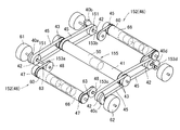
図25に示す物品移動装置150は、カム40a,40b,40c,40dの回転軸と、走行輪61,62の回転軸を共通のものとし、軸受け151によって、カム40a,40b,40c,40dの回転軸と、走行輪61,62の回転軸を相対回転させた例である。
図25に示す物品移動装置150は、軸部分を除いて前述した実施形態の物品移動装置6と同一であるから、同一の部材に同一の番号を付して重複した説明を省略する。
In the
Since the
物品移動装置150の走行機構152は、原則的に図8に示す前述した実施形態の物品移動装置6と同一である。
物品移動装置150の走行機構152は、図27の様に、二組の走行機器46によって構成されており、二組の走行機器46はいずれも走行用モータ内蔵ローラ60と、走行輪61,62及び歯付きベルト63によって構成されている。そして走行用モータ内蔵ローラ60のローラ本体66の外周に歯付きプーリ47が2個装着されている。
走行輪61,62は、回転軸153に対して一体的に固定されている。回転軸153は、図示しない軸受けによって回転可能に支持されている。また回転軸153には歯付きプーリ48が一体的に取り付けられている。
そして走行用モータ内蔵ローラ60の歯付きプーリ47と、走行輪61,62側の歯付きプーリ48の両者に歯付きベルト63が係合している。
In principle, the traveling
As shown in FIG. 27, the traveling
The traveling
The
従って走行用モータ内蔵ローラ60を回転駆動させると、その回転力が歯付きプーリ47、歯付きプーリ47を介して歯付きプーリ48に伝動され、走行輪61,62が回転する。
Therefore, when the
物品移動装置150の昇降機構155は、図27の様に、4個のカム40a,40b,40c,40dと、昇降用モータ内蔵ローラ41及び両者を係合する動力伝導部によって構成されている。
ここで、カム40a,40b,40c,40dの回転軸は、中空であり、軸受け151を介して走行機構152の回転軸153a,153b,153c,153dに外嵌されている。
そのため昇降機構155のカム40a,40b,40c,40dと、走行輪61,62は軸を共有し、カム40と走行輪61,62は相対回転可能であって、共通の軸線回りを回動する。
本実施形態においてもローラ本体50の外周に歯付きプーリ43が4個装着されている。歯付きプーリ43は、ローラ本体50の両端に2個ずつ設けられている。
また昇降用モータ内蔵ローラ41の4個の歯付きプーリ43と、カム40a,40b,40c,40dの歯付きプーリ42の両者にそれぞれ歯付きベルト45が係合している。 昇降用モータ内蔵ローラ41を駆動させると、ローラ本体50の外周に設けられた4個の歯付きプーリ43が回転し、当該回転が歯付きベルト45を介してカム40a,40b,40c,40d側の歯付きプーリ42に伝動され、カム40a,40b,40c,40dが走行機構152の回転軸153a,153b,153c,153dを中心として回動する。
As shown in FIG. 27, the elevating
Here, the rotating shafts of the
Therefore, the
Also in this embodiment, four
Further, the
図25に示す物品移動装置150では、カム40a,40b,40c,40dを走行機構152の回転軸153a,153b,153c,153dに外嵌させたが、カム40a,40b,40c,40dに回転軸を設け、走行機構152の回転軸153a,153b,153c,153dを外嵌させてもよい。
In the
以上説明した物品移動装置6等では、物体検知手段101,102が保持部材31に外付けされていたが、図28に示す物品移動装置160の様に、保持部材161の内面側に物体検知手段101,102を設けてもよい。
図28に示す物品移動装置160では、保持部材161は笠状であり、天面壁162の周囲に側壁163が垂下されている。
In the
In the
物品移動装置160では、保持部材161の前後方向(A側とB側)の側壁163に窓165が開口している。
また物品移動装置160では、図29に示すように保持部材161の側壁163で囲まれた領域にブラケット166が設けられ、当該ブラケット166に物体検知手段101,102が取り付けられている。物体検知手段101,102の高さは、保持部材161の窓165と一致し、物体検知手段101,102が照射する超音波やレーザー光が、窓165を通して外部に放射され、対象物によって反射した超音波やレーザー光が、窓165を通過して物体検知手段101,102に入射される。
In the
Further, in the
1 物品保管装置
2 架台部材
3 収容部
6,110,111,115,150,160,180 物品移動装置
7 本体側センサー保持部材
8a,8b パレット
9 本体側センサー保持部材
17A,17B 位置決め用被検知部材
18 方向検知用被検知部材
22 昇降用モータ
26a,26b 昇降側センサー保持部材
31 保持部材
35 昇降機構
38 制御装置
41 走行用モータ内蔵ローラモータ
55a,b,c,d 爪収納部材
60 走行用モータ内蔵ローラ
52a,52b 位置確認検知センサー
53 方向検知センサー
101,102 物体検知手段
103 センサー(長さ測定手段)
117 上部確認センサー
1
117 Top confirmation sensor
Claims (14)
複数の物品を載置する架台部材と、自走して前記物品を移動させる物品移動装置を有し、
架台部材は、走行路と、前記物品の移動方向にのびその上に前記物品が載置される2列以上の載置部を有し、
物品移動装置は、動力によって回転する走行輪と、物品を保持する保持部材と、当該保持部材を昇降させる昇降機構とを有し、
物品移動装置は、載置部の間に配されていて走行輪を回転することにより走行路を走行可能であり、保持部材を降下した際には保持部材が載置部の上端よりも下に沈み、保持部材を上昇した際には保持部材が載置部の上端よりも上に突出し、
物品移動装置を前記物品の下に移動した後に保持部材を上昇させて保持部材で前記物品をすくい上げ、走行輪を回転させて物品移動装置を移動し、保持部材を降下させて前記物品を架台部材の他の位置に移動させることが可能であり、
載置部に載置された既存の物体の存在を検知する物体検知手段を有し、当該物体検知手段は昇降する部材に取り付けられており、
物品の長さを測定する長さ測定手段を有し、当該長さ測定手段は物品移動装置の上方に物品が存在するか否かを検知する存在検知手段を有し、
物品移動装置を物品の下に潜りこませた状態で物品移動装置を走行させ、存在検知手段の検知状況と物品移動装置の走行距離によって物品の長さを測定することを特徴とする物品保管装置。 In an article storage device capable of accommodating a plurality of articles and having a function of moving the articles.
It has a pedestal member on which a plurality of articles are placed and an article moving device that self-propells to move the articles.
The gantry member has a traveling path and two or more rows of mounting portions on which the article is placed extending in the moving direction of the article.
The article moving device has a traveling wheel that is rotated by power, a holding member that holds the article, and an elevating mechanism that raises and lowers the holding member.
The article moving device is arranged between the mounting portions and can travel on the traveling path by rotating the traveling wheels, and when the holding member is lowered, the holding member is below the upper end of the mounting portion. When it sinks and the holding member is raised, the holding member protrudes above the upper end of the mounting portion, and the holding member protrudes above the upper end.
After moving the article moving device under the article, the holding member is raised to scoop up the article with the holding member, the traveling wheel is rotated to move the article moving device, and the holding member is lowered to mount the article on the gantry member. It is possible to move it to another position,
It has an object detection means that detects the existence of an existing object placed on the mounting part, and the object detection means is attached to a member that moves up and down.
It has a length measuring means for measuring the length of an article, and the length measuring means has an existence detecting means for detecting whether or not an article is present above the article moving device.
An article storage device characterized in that the article moving device is run with the article moving device submerged under the article, and the length of the article is measured according to the detection status of the presence detection means and the mileage of the article moving device. ..
複数の物品を載置する架台部材と、自走して前記物品を移動させる物品移動装置を有し、
架台部材は、走行路と、前記物品の移動方向にのびその上に前記物品が載置される2列以上の載置部を有し、
物品移動装置は、動力によって回転する走行輪と、物品を保持する保持部材と、当該保持部材を昇降させる昇降機構とを有し、
物品移動装置は、載置部の間に配されていて走行輪を回転することにより走行路を走行可能であり、保持部材を降下した際には保持部材が載置部の上端よりも下に沈み、保持部材を上昇した際には保持部材が載置部の上端よりも上に突出し、
物品移動装置を前記物品の下に移動した後に保持部材を上昇させて保持部材で前記物品をすくい上げ、走行輪を回転させて物品移動装置を移動し、保持部材を降下させて前記物品を架台部材の他の位置に移動させることが可能であり、
載置部に載置された既存の物体の存在を検知する物体検知手段を有し、当該物体検知手段は昇降する部材に取り付けられており、
一対の検知センサーと被検知部材によって構成される方向検知手段を有し、
前記物品移動装置に検知センサー又は被検知部材のいずれか一方があり、前記架台部材に検知センサー又は被検知部材の他方があり、
前記一対の検知センサーと被検知部材の取り付け位置は、物品移動装置の一辺側が特定の方向に向いて架台部材の端部近傍にある場合に検知センサーが被検知部材を検知し、物品移動装置の前記一辺側が前記特定の方向とは逆に向いて架台部材の端部近傍にある場合に検知センサーが被検知部材を検知し得ない位置であり、
走行方向の前後を決める前後決定手段を有し、検知センサーが被検知部材を検知した場合には、いずれか一方側が前進方向となる様に走行輪が回転し、検知センサーが被検知部材を検知しない場合には、他方側が前進方向となる様に走行輪が回転することを特徴とする物品保管装置。 In an article storage device capable of accommodating a plurality of articles and having a function of moving the articles.
It has a pedestal member on which a plurality of articles are placed and an article moving device that self-propells to move the articles.
The gantry member has a traveling path and two or more rows of mounting portions on which the article is placed extending in the moving direction of the article.
The article moving device has a traveling wheel that is rotated by power, a holding member that holds the article, and an elevating mechanism that raises and lowers the holding member.
The article moving device is arranged between the mounting portions and can travel on the traveling path by rotating the traveling wheels, and when the holding member is lowered, the holding member is below the upper end of the mounting portion. When it sinks and the holding member is raised, the holding member protrudes above the upper end of the mounting portion, and the holding member protrudes above the upper end.
After moving the article moving device under the article, the holding member is raised to scoop up the article with the holding member, the traveling wheel is rotated to move the article moving device, and the holding member is lowered to mount the article on the gantry member. It is possible to move it to another position,
It has an object detection means that detects the existence of an existing object placed on the mounting part, and the object detection means is attached to a member that moves up and down.
It has a direction detection means composed of a pair of detection sensors and a member to be detected.
The article moving device has either a detection sensor or a member to be detected, and the gantry member has the other of the detection sensor or the member to be detected.
Regarding the mounting position of the pair of detection sensors and the member to be detected, the detection sensor detects the member to be detected when one side of the article moving device faces a specific direction and is near the end of the gantry member, and the article moving device is attached. This is a position where the detection sensor cannot detect the member to be detected when the one side is facing away from the specific direction and is near the end of the gantry member.
It has a front-rear determination means that determines the front-back direction of the traveling direction, and when the detection sensor detects the detected member, the traveling wheel rotates so that one side is in the forward direction, and the detection sensor detects the detected member. If not, the article storage device is characterized in that the traveling wheel rotates so that the other side is in the forward direction.
複数の物品を載置する架台部材と、自走して前記物品を移動させる物品移動装置を有し、
架台部材は、走行路と、前記物品の移動方向にのびその上に前記物品が載置される2列以上の載置部を有し、
物品移動装置は、動力によって回転する走行輪と、物品を保持する保持部材と、当該保持部材を昇降させる昇降機構とを有し、
物品移動装置は、載置部の間に配されていて走行輪を回転することにより走行路を走行可能であり、保持部材を降下した際には保持部材が載置部の上端よりも下に沈み、保持部材を上昇した際には保持部材が載置部の上端よりも上に突出し、
物品移動装置を前記物品の下に移動した後に保持部材を上昇させて保持部材で前記物品をすくい上げ、走行輪を回転させて物品移動装置を移動し、保持部材を降下させて前記物品を架台部材の他の位置に移動させることが可能であり、
載置部に載置された既存の物体の存在を検知する物体検知手段を有し、当該物体検知手段は昇降する部材に取り付けられており、
架台部材の端部に物品移動装置の落下を防止するためのストッパーがあり、
検知センサーと被検知部材を有し、
前記物品移動装置に検知センサー又は被検知部材のいずれか一方があり、前記ストッパーに検知センサー又は被検知部材の他方があり、
前記検知センサーと被検知部材の取り付け位置は、物品移動装置の一辺側が特定の方向に向いて架台部材の端部近傍にある場合に検知センサーが被検知部材を検知し、物品移動装置の前記一辺側が前記特定の方向とは逆に向いて架台部材の端部近傍にある場合に検知センサーが被検知部材を検知し得ない位置であり、
走行方向の前後を決める前後決定手段を有し、検知センサーが被検知部材を検知した場合には、いずれか一方側が前進方向となる様に走行輪が回転し、検知センサーが被検知部材を検知しない場合には、他方側が前進方向となる様に走行輪が回転することを特徴とする物品保管装置。 In an article storage device capable of accommodating a plurality of articles and having a function of moving the articles.
It has a pedestal member on which a plurality of articles are placed and an article moving device that self-propells to move the articles.
The gantry member has a traveling path and two or more rows of mounting portions on which the article is placed extending in the moving direction of the article.
The article moving device has a traveling wheel that is rotated by power, a holding member that holds the article, and an elevating mechanism that raises and lowers the holding member.
The article moving device is arranged between the mounting portions and can travel on the traveling path by rotating the traveling wheels, and when the holding member is lowered, the holding member is below the upper end of the mounting portion. When it sinks and the holding member is raised, the holding member protrudes above the upper end of the mounting portion, and the holding member protrudes above the upper end.
After moving the article moving device under the article, the holding member is raised to scoop up the article with the holding member, the traveling wheel is rotated to move the article moving device, and the holding member is lowered to mount the article on the gantry member. It is possible to move it to another position,
It has an object detection means that detects the existence of an existing object placed on the mounting part, and the object detection means is attached to a member that moves up and down.
There is a stopper at the end of the gantry member to prevent the article moving device from falling.
It has a detection sensor and a member to be detected,
The article moving device has either a detection sensor or a member to be detected, and the stopper has the other of the detection sensor or the member to be detected.
The detection sensor and the detected member are attached to the one side of the article moving device when the detection sensor detects the detected member when one side of the article moving device faces a specific direction and is near the end of the gantry member. This is a position where the detection sensor cannot detect the member to be detected when the side is facing away from the specific direction and is near the end of the gantry member.
It has a front-rear determination means that determines the front-back direction of the traveling direction, and when the detection sensor detects the detected member, the traveling wheel rotates so that one side is in the forward direction, and the detection sensor detects the detected member. If not, the article storage device is characterized in that the traveling wheel rotates so that the other side is in the forward direction.
複数の物品を載置する架台部材と、自走して前記物品を移動させる物品移動装置を有し、
架台部材は、走行路と、前記物品の移動方向にのびその上に前記物品が載置される2列以上の載置部を有し、
物品移動装置は、動力によって回転する走行輪と、物品を保持する保持部材と、当該保持部材を昇降させる昇降機構とを有し、
物品移動装置は、載置部の間に配されていて走行輪を回転することにより走行路を走行可能であり、保持部材を降下した際には保持部材が載置部の上端よりも下に沈み、保持部材を上昇した際には保持部材が載置部の上端よりも上に突出し、
物品移動装置を前記物品の下に移動した後に保持部材を上昇させて保持部材で前記物品をすくい上げ、走行輪を回転させて物品移動装置を移動し、保持部材を降下させて前記物品を架台部材の他の位置に移動させることが可能であり、
載置部に載置された既存の物体の存在を検知する物体検知手段を有し、当該物体検知手段は昇降する部材に取り付けられており、
検知センサーと被検知部材を有し、
物品移動装置の走行方向に対して両側の側面部分にそれぞれ検知センサー又は被検知部材が設けられており、
前記検知センサーと被検知部材の取り付け位置は、物品移動装置の走行方向に沿った一辺側が特定の方向に向いて架台部材の端部近傍にある場合に一方の検知センサーだけが被検知部材を検知し、物品移動装置の前記一辺側が前記特定の方向とは逆に向いて架台部材の端部近傍にある場合は他方の検知センサーだけが被検知部材を検知する位置であり、
走行方向の前後を決める前後決定手段を有し、一方の検知センサーが被検知部材を検知した場合には、いずれか一方側が前進方向となる様に走行輪が回転し、他方の検知センサーが被検知部材を検知した場合には他方側が前進方向となる様に走行輪が回転することを特徴とする物品保管装置。 In an article storage device capable of accommodating a plurality of articles and having a function of moving the articles.
It has a pedestal member on which a plurality of articles are placed and an article moving device that self-propells to move the articles.
The gantry member has a traveling path and two or more rows of mounting portions on which the article is placed extending in the moving direction of the article.
The article moving device has a traveling wheel that is rotated by power, a holding member that holds the article, and an elevating mechanism that raises and lowers the holding member.
The article moving device is arranged between the mounting portions and can travel on the traveling path by rotating the traveling wheels, and when the holding member is lowered, the holding member is below the upper end of the mounting portion. When it sinks and the holding member is raised, the holding member protrudes above the upper end of the mounting portion, and the holding member protrudes above the upper end.
After moving the article moving device under the article, the holding member is raised to scoop up the article with the holding member, the traveling wheel is rotated to move the article moving device, and the holding member is lowered to mount the article on the gantry member. It is possible to move it to another position,
It has an object detection means that detects the existence of an existing object placed on the mounting part, and the object detection means is attached to a member that moves up and down .
It has a detection sensor and a member to be detected,
A detection sensor or a member to be detected is provided on each of the side surface portions on both sides with respect to the traveling direction of the article moving device.
As for the mounting position of the detection sensor and the detected member, only one of the detection sensors detects the detected member when one side of the article moving device is oriented in a specific direction and is near the end of the gantry member. However, when the one side of the article moving device faces in the opposite direction to the specific direction and is near the end of the gantry member, only the other detection sensor is in the position to detect the detected member.
It has a front-rear determination means for determining the front-rear direction of the traveling direction, and when one of the detection sensors detects a member to be detected, the traveling wheel rotates so that one side is in the forward direction, and the other detection sensor is covered. An article storage device characterized in that when a detection member is detected, the traveling wheel rotates so that the other side is in the forward direction.
複数の物品を載置する架台部材と、自走して前記物品を移動させる物品移動装置を有し、
架台部材は、走行路と、前記物品の移動方向にのびその上に前記物品が載置される2列以上の載置部を有し、
物品移動装置は、動力によって回転する走行輪と、物品を保持する保持部材と、当該保持部材を昇降させる昇降機構とを有し、
物品移動装置は、載置部の間に配されていて走行輪を回転することにより走行路を走行可能であり、保持部材を降下した際には保持部材が載置部の上端よりも下に沈み、保持部材を上昇した際には保持部材が載置部の上端よりも上に突出し、
物品移動装置を前記物品の下に移動した後に保持部材を上昇させて保持部材で前記物品をすくい上げ、走行輪を回転させて物品移動装置を移動し、保持部材を降下させて前記物品を架台部材の他の位置に移動させることが可能であり、
一対の検知センサーと被検知部材によって構成される方向検知手段を有し、
前記物品移動装置に検知センサー又は被検知部材のいずれか一方があり、前記架台部材に検知センサー又は被検知部材の他方があり、
前記一対の検知センサーと被検知部材の取り付け位置は、物品移動装置の一辺側が特定の方向に向いて架台部材の端部近傍にある場合に検知センサーが被検知部材を検知し、物品移動装置の前記一辺側が前記特定の方向とは逆に向いて架台部材の端部近傍にある場合に検知センサーが被検知部材を検知し得ない位置であり、
走行方向の前後を決める前後決定手段を有し、検知センサーが被検知部材を検知した場合には、いずれか一方側が前進方向となる様に走行輪が回転し、検知センサーが被検知部材を検知しない場合には、他方側が前進方向となる様に走行輪が回転することを特徴とする物品保管装置。 In an article storage device capable of accommodating a plurality of articles and having a function of moving the articles.
It has a pedestal member on which a plurality of articles are placed and an article moving device that self-propells to move the articles.
The gantry member has a traveling path and two or more rows of mounting portions on which the article is placed extending in the moving direction of the article.
The article moving device has a traveling wheel that is rotated by power, a holding member that holds the article, and an elevating mechanism that raises and lowers the holding member.
The article moving device is arranged between the mounting portions and can travel on the traveling path by rotating the traveling wheels, and when the holding member is lowered, the holding member is below the upper end of the mounting portion. When it sinks and the holding member is raised, the holding member protrudes above the upper end of the mounting portion, and the holding member protrudes above the upper end.
After moving the article moving device under the article, the holding member is raised to scoop up the article with the holding member, the traveling wheel is rotated to move the article moving device, and the holding member is lowered to mount the article on the gantry member. It is possible to move it to another position,
It has a direction detection means composed of a pair of detection sensors and a member to be detected.
The article moving device has either a detection sensor or a member to be detected, and the gantry member has the other of the detection sensor or the member to be detected.
Regarding the mounting position of the pair of detection sensors and the member to be detected, the detection sensor detects the member to be detected when one side of the article moving device faces a specific direction and is near the end of the gantry member, and the article moving device is attached. This is a position where the detection sensor cannot detect the member to be detected when the one side is facing away from the specific direction and is near the end of the gantry member.
It has a front-rear determination means that determines the front-back direction of the traveling direction, and when the detection sensor detects the detected member, the traveling wheel rotates so that one side is in the forward direction, and the detection sensor detects the detected member. If not, the article storage device is characterized in that the traveling wheel rotates so that the other side is in the forward direction.
複数の物品を載置する架台部材と、自走して前記物品を移動させる物品移動装置を有し、
架台部材は、走行路と、前記物品の移動方向にのびその上に前記物品が載置される2列以上の載置部を有し、
物品移動装置は、動力によって回転する走行輪と、物品を保持する保持部材と、当該保持部材を昇降させる昇降機構とを有し、
物品移動装置は、載置部の間に配されていて走行輪を回転することにより走行路を走行可能であり、保持部材を降下した際には保持部材が載置部の上端よりも下に沈み、保持部材を上昇した際には保持部材が載置部の上端よりも上に突出し、
物品移動装置を前記物品の下に移動した後に保持部材を上昇させて保持部材で前記物品をすくい上げ、走行輪を回転させて物品移動装置を移動し、保持部材を降下させて前記物品を架台部材の他の位置に移動させることが可能であり、
載置部に載置された既存の物体の存在を検知する物体検知手段を有し、当該物体検知手段は昇降する部材に取り付けられており、
物品の姿勢を修正する修正ガイド部材があり、当該修正ガイド部材は載置部の外側又はその近傍に設けられ、載置部に載置した物品の姿勢が正規の状態から外れている状態で物品移動装置を走行させた場合に前記修正ガイド部材が物品に接触して物品の姿勢が正規の状態に修正することを特徴とする物品保管装置。
In an article storage device capable of accommodating a plurality of articles and having a function of moving the articles.
It has a pedestal member on which a plurality of articles are placed and an article moving device that self-propells to move the articles.
The gantry member has a traveling path and two or more rows of mounting portions on which the article is placed extending in the moving direction of the article.
The article moving device has a traveling wheel that is rotated by power, a holding member that holds the article, and an elevating mechanism that raises and lowers the holding member.
The article moving device is arranged between the mounting portions and can travel on the traveling path by rotating the traveling wheels, and when the holding member is lowered, the holding member is below the upper end of the mounting portion. When it sinks and the holding member is raised, the holding member protrudes above the upper end of the mounting portion, and the holding member protrudes above the upper end.
After moving the article moving device under the article, the holding member is raised to scoop up the article with the holding member, the traveling wheel is rotated to move the article moving device, and the holding member is lowered to mount the article on the gantry member. It is possible to move it to another position,
It has an object detection means that detects the existence of an existing object placed on the mounting part, and the object detection means is attached to a member that moves up and down.
There is a correction guide member that corrects the posture of the article, and the correction guide member is provided outside or near the mounting portion, and the article is placed in a state where the posture of the article placed on the mounting portion is out of the normal state. An article storage device characterized in that when the moving device is moved, the correction guide member comes into contact with the article and the posture of the article is corrected to a normal state.
複数の物品を載置する架台部材と、自走して前記物品を移動させる物品移動装置を有し、
架台部材は、走行路と、前記物品の移動方向にのびその上に前記物品が載置される2列以上の載置部を有し、
物品移動装置は、動力によって回転する走行輪と、物品を保持する保持部材と、当該保持部材を昇降させる昇降機構とを有し、
物品移動装置は、載置部の間に配されていて走行輪を回転することにより走行路を走行可能であり、保持部材を降下した際には保持部材が載置部の上端よりも下に沈み、保持部材を上昇した際には保持部材が載置部の上端よりも上に突出し、
物品移動装置を前記物品の下に移動した後に保持部材を上昇させて保持部材で前記物品をすくい上げ、走行輪を回転させて物品移動装置を移動し、保持部材を降下させて前記物品を架台部材の他の位置に移動させることが可能であり、
前記物品移動装置は別途用意の搬送装置によって搬送可能であり、前記搬送装置は爪を有し、物品移動装置の本体部に前記爪が挿入される爪収納部材が設けられており、爪収納部材の一部は物品移動装置の本体部が構成する平面から外側にはみ出たはみ出し部があり、
上部に物体が存在するか否かを検知する上部確認センサーを有し、当該上部確認センサーが、爪収納部材の前記はみ出し部に設けられていることを特徴とする物品保管装置。 In an article storage device capable of accommodating a plurality of articles and having a function of moving the articles.
It has a pedestal member on which a plurality of articles are placed and an article moving device that self-propells to move the articles.
The gantry member has a traveling path and two or more rows of mounting portions on which the article is placed extending in the moving direction of the article.
The article moving device has a traveling wheel that is rotated by power, a holding member that holds the article, and an elevating mechanism that raises and lowers the holding member.
The article moving device is arranged between the mounting portions and can travel on the traveling path by rotating the traveling wheels, and when the holding member is lowered, the holding member is below the upper end of the mounting portion. When it sinks and the holding member is raised, the holding member protrudes above the upper end of the mounting portion, and the holding member protrudes above the upper end.
After moving the article moving device under the article, the holding member is raised to scoop up the article with the holding member, the traveling wheel is rotated to move the article moving device, and the holding member is lowered to mount the article on the gantry member. It is possible to move it to another position,
The article moving device can be conveyed by a separately prepared transport device, and the transport device has a claw, and a claw storage member into which the claw is inserted is provided in the main body of the article moving device. some are protruding outwardly from the plane that constitutes the main body of the article moving device may look out portion,
An article storage device having an upper part confirmation sensor that detects whether or not an object is present on the upper part, and the upper part confirmation sensor is provided at the protruding portion of the claw storage member.
動力によって回転する走行輪と、物品を保持する保持部材と、当該保持部材を昇降させる昇降機構とを有し、
物品移動装置は、載置部の間に配されていて走行輪を回転することにより走行路を走行可能であり、保持部材を降下した際には保持部材が載置部の上端よりも下に沈み、保持部材を上昇した際には保持部材が載置部の上端よりも上に突出し、
物品移動装置を前記物品の下に移動した後に保持部材を上昇させて保持部材で前記物品をすくい上げ、走行輪を回転させて物品移動装置を移動し、保持部材を降下させて前記物品を架台部材の他の位置に移動させることが可能であり、
前記物品移動装置は別途用意の搬送装置によって搬送可能であり、前記搬送装置は爪を有し、物品移動装置の本体部に前記爪が挿入される爪収納部材が設けられており、爪収納部材の一部は物品移動装置の本体部が構成する平面から外側にはみ出たはみ出し部があり、
上部に物体が存在するか否かを検知する上部確認センサーを有し、当該上部確認センサーが、爪収納部材の前記はみ出し部に設けられていることを特徴とする物品移動装置。 In an article moving device which is arranged on a traveling path and a pedestal member having two or more rows of mounting portions extending in a straight line and transports articles on the traveling path.
It has a traveling wheel that rotates by power, a holding member that holds an article, and an elevating mechanism that raises and lowers the holding member.
The article moving device is arranged between the mounting portions and can travel on the traveling path by rotating the traveling wheels, and when the holding member is lowered, the holding member is below the upper end of the mounting portion. When it sinks and the holding member is raised, the holding member protrudes above the upper end of the mounting portion, and the holding member protrudes above the upper end.
After moving the article moving device under the article, the holding member is raised to scoop up the article with the holding member, the traveling wheel is rotated to move the article moving device, and the holding member is lowered to mount the article on the gantry member. It is possible to move it to another position,
The article moving device can be conveyed by a separately prepared transport device, and the transport device has a claw, and a claw storage member into which the claw is inserted is provided in the main body of the article moving device. some are protruding outwardly from the plane that constitutes the main body of the article moving device may look out portion,
An article moving device having an upper part confirmation sensor that detects whether or not an object is present on the upper part, and the upper part confirmation sensor is provided at the protruding portion of the claw storage member.
複数の物品を載置する架台部材と、自走して前記物品を移動させる物品移動装置を有し、
架台部材は、走行路と、前記物品の移動方向にのびその上に前記物品が載置される2列以上の載置部を有し、
物品移動装置は、動力によって正方向及び逆方向に回転する走行輪と、物品を保持する保持部材と、当該保持部材を昇降させる昇降機構とを有し、
物品移動装置は、載置部の間に配されていて走行輪を回転することにより走行路を正方向及び逆方向に走行可能であり、保持部材を降下した際には保持部材が載置部の上端よりも下に沈み、保持部材を上昇した際には保持部材が載置部の上端よりも上に突出し、
物品移動装置を前記物品の下に移動した後に保持部材を上昇させて保持部材で前記物品をすくい上げ、走行輪を回転させて物品移動装置を移動し、保持部材を降下させて前記物品を架台部材の他の位置に移動させることが可能であり、
載置部に載置された既存の物体の存在を検知する物体検知手段が物品移動装置の正方向側と逆方向側の双方に設けられており、
物品移動装置は蓄電池を搭載し、当該蓄電池に給電するコネクタが、物品移動装置の正方向側と逆方向側の双方に設けられていることを特徴とする物品保管装置。 In an article storage device capable of accommodating a plurality of articles and having a function of moving the articles.
It has a pedestal member on which a plurality of articles are placed and an article moving device that self-propells to move the articles.
The gantry member has a traveling path and two or more rows of mounting portions on which the article is placed extending in the moving direction of the article.
The article moving device has a traveling wheel that rotates in the forward and reverse directions by power, a holding member that holds the article, and an elevating mechanism that raises and lowers the holding member.
The article moving device is arranged between the mounting portions and can travel in the forward and reverse directions on the traveling path by rotating the traveling wheels. When the holding member is lowered, the holding member is placed on the mounting portion. When the holding member is raised, the holding member protrudes above the upper end of the mounting portion.
After moving the article moving device under the article, the holding member is raised to scoop up the article with the holding member, the traveling wheel is rotated to move the article moving device, and the holding member is lowered to mount the article on the gantry member. It is possible to move it to another position,
Object detection means for detecting the presence of an existing object mounted on the mounting portion is provided on both the forward side and the reverse side of the article moving device.
The article moving device is an article storage device in which a storage battery is mounted and connectors for supplying power to the storage battery are provided on both the forward side and the reverse direction side of the article moving device.
Applications Claiming Priority (2)
| Application Number | Priority Date | Filing Date | Title |
|---|---|---|---|
| JP2016007313 | 2016-01-18 | ||
| JP2016007313 | 2016-01-18 |
Publications (2)
| Publication Number | Publication Date |
|---|---|
| JP2017128446A JP2017128446A (en) | 2017-07-27 |
| JP6892068B2 true JP6892068B2 (en) | 2021-06-18 |
Family
ID=59395353
Family Applications (1)
| Application Number | Title | Priority Date | Filing Date |
|---|---|---|---|
| JP2017006623A Active JP6892068B2 (en) | 2016-01-18 | 2017-01-18 | Goods storage device and goods moving device |
Country Status (1)
| Country | Link |
|---|---|
| JP (1) | JP6892068B2 (en) |
Families Citing this family (7)
| Publication number | Priority date | Publication date | Assignee | Title |
|---|---|---|---|---|
| JP6980193B2 (en) * | 2018-01-29 | 2021-12-15 | 伊東電機株式会社 | Goods storage device and goods moving device |
| JP6672430B2 (en) * | 2018-02-21 | 2020-03-25 | 住友重機械搬送システム株式会社 | Automatic warehouse system |
| JP2020040747A (en) * | 2018-09-07 | 2020-03-19 | 株式会社オカムラ | Conveying truck |
| JP7074009B2 (en) * | 2018-10-01 | 2022-05-24 | 株式会社ダイフク | Goods storage equipment |
| CN110027832A (en) * | 2019-05-16 | 2019-07-19 | 山东大学 | A kind of shelf goods cage transfer shuttle and its application |
| JP2023058150A (en) * | 2021-10-13 | 2023-04-25 | 株式会社ダイフク | Article conveyance facility |
| KR102458749B1 (en) * | 2022-01-28 | 2022-10-27 | (주)신우유비코스 | Parking system and Parking-performing robot that recognizes pallets through lidar module |
Family Cites Families (8)
| Publication number | Priority date | Publication date | Assignee | Title |
|---|---|---|---|---|
| JPS5135751Y2 (en) * | 1971-11-11 | 1976-09-02 | ||
| JPS549838Y2 (en) * | 1975-10-02 | 1979-05-09 | ||
| JP3138983B2 (en) * | 1996-09-10 | 2001-02-26 | 株式会社ダイフク | Loading / unloading equipment for storage shelves |
| JP3371955B2 (en) * | 1999-07-13 | 2003-01-27 | 村田機械株式会社 | Lifter |
| JP2002080107A (en) * | 2000-09-04 | 2002-03-19 | Murata Mach Ltd | Conveying device having dolly truck and conveying system |
| JP6298316B2 (en) * | 2014-02-24 | 2018-03-20 | 株式会社岡村製作所 | Transport cart |
| JP6231905B2 (en) * | 2014-02-24 | 2017-11-15 | 株式会社岡村製作所 | Transport cart |
| JP6414403B2 (en) * | 2014-07-17 | 2018-10-31 | 株式会社ダイフク | Goods storage equipment |
-
2017
- 2017-01-18 JP JP2017006623A patent/JP6892068B2/en active Active
Also Published As
| Publication number | Publication date |
|---|---|
| JP2017128446A (en) | 2017-07-27 |
Similar Documents
| Publication | Publication Date | Title |
|---|---|---|
| JP6892068B2 (en) | Goods storage device and goods moving device | |
| US9994394B2 (en) | Side arm transfer device | |
| US20090162176A1 (en) | Stacker crane and method for operating a stacker crane | |
| JP4577568B2 (en) | Article conveying device in article storage facility | |
| JP4756367B2 (en) | Goods storage equipment | |
| US10431485B2 (en) | Article transport facility | |
| JP2005314116A (en) | Traveling device of movable body | |
| JP2007269452A (en) | Safety device for unmanned fork lift | |
| JP4941728B2 (en) | Article conveying device | |
| JP4947359B2 (en) | Article conveying device | |
| JP6336502B2 (en) | Vehicle width detection device, mechanical parking facility equipped with the same | |
| JP5382407B2 (en) | Abnormality detection device for stacker crane | |
| JP5445399B2 (en) | Transfer device and first-in-stock determination method | |
| JP2003073093A (en) | Automated forklift | |
| JPH0515456Y2 (en) | ||
| JP5267856B2 (en) | Stacker crane and article storage equipment | |
| JP6980193B2 (en) | Goods storage device and goods moving device | |
| JP4399737B2 (en) | Article transfer device | |
| JP2003081595A (en) | Unattended forklift | |
| JP2002068406A (en) | Double storage preventing device for automated storage and retrieving warehouse | |
| JP2009214986A (en) | Article conveying device | |
| JP4968508B2 (en) | Goods storage device | |
| JP2000229706A (en) | Travel gear for movable body | |
| KR20190086992A (en) | Storage and Transportable Transport Equipment for Parts | |
| JP5105182B2 (en) | Article conveying device |
Legal Events
| Date | Code | Title | Description |
|---|---|---|---|
| AA64 | Notification of invalidation of claim of internal priority (with term) |
Free format text: JAPANESE INTERMEDIATE CODE: A241764 Effective date: 20170209 |
|
| A521 | Written amendment |
Free format text: JAPANESE INTERMEDIATE CODE: A523 Effective date: 20170317 |
|
| A621 | Written request for application examination |
Free format text: JAPANESE INTERMEDIATE CODE: A621 Effective date: 20191224 |
|
| A977 | Report on retrieval |
Free format text: JAPANESE INTERMEDIATE CODE: A971007 Effective date: 20201112 |
|
| A131 | Notification of reasons for refusal |
Free format text: JAPANESE INTERMEDIATE CODE: A131 Effective date: 20201126 |
|
| A601 | Written request for extension of time |
Free format text: JAPANESE INTERMEDIATE CODE: A601 Effective date: 20210120 |
|
| A521 | Written amendment |
Free format text: JAPANESE INTERMEDIATE CODE: A523 Effective date: 20210318 |
|
| TRDD | Decision of grant or rejection written | ||
| A01 | Written decision to grant a patent or to grant a registration (utility model) |
Free format text: JAPANESE INTERMEDIATE CODE: A01 Effective date: 20210430 |
|
| A61 | First payment of annual fees (during grant procedure) |
Free format text: JAPANESE INTERMEDIATE CODE: A61 Effective date: 20210518 |
|
| R150 | Certificate of patent or registration of utility model |
Ref document number: 6892068 Country of ref document: JP Free format text: JAPANESE INTERMEDIATE CODE: R150 |