JP5487614B2 - Automatic warehouse - Google Patents
Automatic warehouse Download PDFInfo
- Publication number
- JP5487614B2 JP5487614B2 JP2008327745A JP2008327745A JP5487614B2 JP 5487614 B2 JP5487614 B2 JP 5487614B2 JP 2008327745 A JP2008327745 A JP 2008327745A JP 2008327745 A JP2008327745 A JP 2008327745A JP 5487614 B2 JP5487614 B2 JP 5487614B2
- Authority
- JP
- Japan
- Prior art keywords
- forks
- crane
- sensor
- fork
- controller
- Prior art date
- Legal status (The legal status is an assumption and is not a legal conclusion. Google has not performed a legal analysis and makes no representation as to the accuracy of the status listed.)
- Expired - Fee Related
Links
- 238000001514 detection method Methods 0.000 claims description 13
- 230000003028 elevating effect Effects 0.000 description 14
- 230000002159 abnormal effect Effects 0.000 description 11
- 230000005856 abnormality Effects 0.000 description 3
- 230000005540 biological transmission Effects 0.000 description 1
- 230000003287 optical effect Effects 0.000 description 1
Images


Landscapes
- Warehouses Or Storage Devices (AREA)
Description
本発明は、複数の収容部を有する枠組棚と、枠組棚に対して移動して収容部にワークを搬入・搬出するスタッカクレーンと、スタッカクレーンを制御するメインコントローラを有する自動倉庫に関する。 The present invention relates to a frame shelf having a plurality of storage units, a stacker crane that moves relative to the frame shelf and loads / unloads workpieces into / from the storage unit, and an automatic warehouse having a main controller that controls the stacker crane.
自動倉庫は、例えば枠組棚と、枠組棚の近傍に設けられる荷受台と、スタッカクレーンを有している(特許文献1参照)。スタッカクレーンは、二つのフォークを有しており、一つのフォークによって小ワークを搬入・搬出し、二つのフォークによって大ワークを搬入・搬出する。荷受台には、三つのセンサが設けられており、三つのセンサからの検知信号に基づいて制御装置が荷受台に設置されたワークが大ワークか小ワークかを判断する。したがって制御装置は、センサからの検知信号に基づいてスタッカクレーンを制御し、スタッカクレーンがフォークによって荷受台からワークを掬い上げ、ワークを荷受台から枠組棚に搬入する。 The automatic warehouse includes, for example, a frame shelf, a load receiving stand provided near the frame shelf, and a stacker crane (see Patent Document 1). The stacker crane has two forks. A small work is loaded and unloaded with one fork, and a large work is loaded and unloaded with two forks. The load receiving table is provided with three sensors. Based on detection signals from the three sensors, the control device determines whether the work installed on the load receiving table is a large work or a small work. Therefore, the control device controls the stacker crane based on the detection signal from the sensor, the stacker crane picks up the work from the load receiving platform by the fork, and carries the work from the load receiving table to the frame shelf.
また従来、スタッカクレーン側にセンサが設けられている自動倉庫も知られている(特許文献2,3参照)。例えば、センサによって荷受台に載置されたワークを検知し、スタッカクレーンから荷受台にワークを二重に載置することを防止する(特許文献2参照)。あるいはセンサによって枠組棚の縦柱を検知して、フォークを縦柱に当たらない位置にスライドさせる(特許文献3参照)。これによってワークを効率良く枠組棚に搬入・搬出することができる。
しかしワークを間違いなく搬入・搬出したいという要望がある。そこで本発明は、枠組棚とスタッカクレーンとの間でワークを間違いなく搬入・搬出し得る自動倉庫を提供することを目的とする。 However, there is a desire to carry in and out workpieces without fail. SUMMARY OF THE INVENTION An object of the present invention is to provide an automatic warehouse that can definitely carry in and out a workpiece between a frame shelf and a stacker crane.
前記課題を解決するために本発明は、各請求項に記載の通りの構成を備える自動倉庫であることを特徴とする。すなわち請求項1に記載の発明によると、スタッカクレーンは、収容部に対して進退する複数のフォークと、複数のフォークの間に設けられて枠組棚側の物体を検知し得るセンサと、フォークを制御するクレーンコントローラを有しており、一つのフォークによって小ワークを搬送し、複数のフォークによって大ワークを搬送する構成である。メインコントローラは、ワークの大きさに関する情報を含む指令信号をクレーンコントローラに発信する。クレーンコントローラは、前記指令信号と、センサからの検知信号に基づいて複数のフォークを制御する。 In order to solve the above-mentioned problems, the present invention is an automatic warehouse having a configuration as described in each claim. That is, according to the first aspect of the present invention, the stacker crane includes a plurality of forks that move forward and backward with respect to the accommodating portion, a sensor that is provided between the forks and that can detect an object on the frame shelf side, and a fork. It has a crane controller to control, and is configured to convey a small work by one fork and to convey a large work by a plurality of forks. The main controller transmits a command signal including information on the size of the workpiece to the crane controller. The crane controller controls a plurality of forks based on the command signal and a detection signal from the sensor.
したがってクレーンコントローラは、センサからの検知信号によってメインコントローラからの指令信号が正しいか否かを判断できる。例えばスタッカクレーンは、メインコントローラからの指令信号によって所定の収容部の前にフォークが移動する。そしてセンサによって所定の収容部内に物体が有るか否かを検知する。そしてクレーンコントローラがその物体を搬出すべき物でないと判断した際にフォークを進退させない。あるいは二つのフォーク間の前方に柱が存在し、二つのフォークに載置されたワークを前進させることでワークが柱に当たると判断した際にフォークを進退させない。これにより枠組棚とスタッカクレーンの間においてワークを間違いなく搬入・搬出することができる。 Therefore, the crane controller can determine whether the command signal from the main controller is correct based on the detection signal from the sensor. For example, in a stacker crane, a fork moves in front of a predetermined accommodating portion in response to a command signal from a main controller. Then, it is detected by a sensor whether or not there is an object in the predetermined accommodating portion. When the crane controller determines that the object is not to be carried out, the fork is not advanced or retracted. Alternatively, there is a pillar in front of the two forks, and when the work placed on the two forks is advanced, the fork is not advanced or retracted when it is determined that the work hits the pillar. As a result, the workpiece can be reliably loaded and unloaded between the frame shelf and the stacker crane.
請求項1に記載の発明によると、センサは、収容部に収容されかつフォーク間の前方に位置する大ワークを検知し、かつ収容部の左右いずれかに配置されてフォーク間の前方に位置しない小ワークを検知しないように複数のフォークの間に設けられる。メインコントローラが所定の収容部から小ワークを搬出する指令信号を発信し、かつセンサが所定の収容部に大ワークが収容されていることを検知した際に、クレーンコントローラがフォークを進出させないように制御する。したがって指令信号に基づいて一つのフォークによって小ワークを搬出する動作が、センサからの検知信号に基づいてクレーンコントローラによって防止され得る。そのため一つのフォークによって大ワークを掬ってしまい、これによって大ワークが倒れてしまうこと(荷崩れ)が防止され得る。 According to the first aspect of the present invention, the sensor detects a large work housed in the housing portion and located in front of the forks , and is disposed on either the left or right of the housing portion and is not located in front of the forks. so as not to detect a small work Ru provided between the plurality of forks. Prevent the crane controller from moving the fork when the main controller sends a command signal to carry out a small work from a predetermined storage part and the sensor detects that a large work is stored in the predetermined storage part. Control. Therefore, the operation of carrying out a small work by one fork based on the command signal can be prevented by the crane controller based on the detection signal from the sensor. Therefore, it is possible to prevent a large work from being rolled up by one fork and thereby causing the large work to fall (load collapse).
(実施の形態1)
実施の形態1を図1〜3にしたがって説明する。図1に示すように自動倉庫1は、一対の枠組棚2と、枠組棚2に対して移動してワーク10を運搬するスタッカクレーン3と、スタッカクレーン3を制御するメインコントローラ5を有している。
(Embodiment 1)
The first embodiment will be described with reference to FIGS. As shown in FIG. 1, the automatic warehouse 1 has a pair of
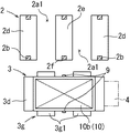
枠組棚2は、図1,2に示すように上下方向に延出する複数の縦柱2bと、水平方向に延出する横柱2cを有している。枠組棚2は、縦柱2bと横柱2cによって区画される収容部2aを上下に複数段、水平方向に複数列有している。収容部2aには、ワーク10が載置される受板2d,2eが設けられる。
As shown in FIGS. 1 and 2, the
受板2d,2eは、図2,3に示すように収容部2aの下側において奥行き方向に延出している。受板2dは、縦柱2bに取付けられて、収容部2aの左右両側に位置する。受板2eは、横柱2cに取付けられて、収容部2aの左右略中央に位置する。受板2d,2eには、これらに跨って小ワーク10aが載置される。三つの受板2d,2eには、これらに跨って大ワーク10bが載置される。したがって収容部2aには、二つの小ワークまたは一つの大ワーク10bが収容され得る。
The receiving
枠組棚2の隣接位置には、図1,2に示すように荷受台6が設けられる。荷受台6には、スタッカクレーン3によって枠組棚2に搬入される予定のワーク10または枠組棚2から搬出されたワーク10が載置され得る。
As shown in FIGS. 1 and 2, a
スタッカクレーン3は、図1に示すように走行台3bと、走行台3bの両端部に立設する一対のマスト3aと、一対のマスト3aの上部を連結する連結部3cを有している。走行台3bには、床面に設けられた走行用レール7aに設置される車輪と、車輪に駆動力を与える走行用モータ3eが設けられる。連結部3cには、枠組棚2の上部間に設けられた案内レール7bに走行可能に設置される走行輪が設けられる。したがってスタッカクレーン3は、走行用モータ3eが制御されることで走行用レール7aと案内レール7bに沿って一対の枠組棚2の間を走行する。
As shown in FIG. 1, the
一対のマスト3aの間には、昇降キャリッジ3dが昇降可能に設けられる。昇降キャリッジ3dには、昇降用モータ3fが設けられており、昇降用モータ3fが制御されることで昇降キャリッジ3dがマスト3aに沿って上下動する。昇降キャリッジ3dには、フォーク装置3gが設けられる。フォーク装置3gは、複数(例えば二つ)のフォーク3g1と、各フォーク3g1を移動させるフォーク用モータ3g2を有している。
An
フォーク3g1は、フォーク用モータ3g2によって収容部2aに対して進退する。小ワーク10aを収容部2aに搬入・搬出する場合は、一つのフォーク3g1によって小ワーク10aを搬送する。したがってスタッカクレーン3は、小ワーク10aを二つ同時に搬送することもできる。大ワーク10bを搬入・搬出する場合は、二つのフォーク3g1によって大ワーク10bを搬送する。
The fork 3g1 moves forward and backward with respect to the
スタッカクレーン3は、上位制御装置であるメインコントローラ5と、下位制御装置であるクレーンコントローラ4によって制御される。メインコントローラ5は、自動倉庫1の入口側に設けられており、作業者が情報を入力する入力部と、入力された情報等を表示する表示部と、情報を記憶する記憶部と、指令信号を発信する発信部を有している。指令信号には、ワークを搬入するか搬出するかの情報と、ワーク10の大きさに関する情報と、搬入・搬出先の情報等が含まれる。
The
クレーンコントローラ4は、図1,2に示すようにスタッカクレーン3に設けられる。クレーンコントローラ4は、メインコントローラ5と電気的に接続されており、メインコントローラ5からの指令信号を受信する受信部と、指令信号を記憶する記憶部と、指令信号に基づいてスタッカクレーン3を制御する制御部を有している。したがってクレーンコントローラ4によってスタッカクレーン3が制御されることで、走行台3bが走行し、昇降キャリッジ3dが昇降する。これにより昇降キャリッジ3dが所定の収容部2aの前に移動する。そして所定の収容部2aにフォーク3g1を進退させかつ昇降キャリッジ3dを昇降させることで、ワーク10を収容部2aに搬入・搬出することができる。
The
昇降キャリッジ3dには、図3に示すように枠組棚2側の物体を検知するためのセンサ9が取付けられている。センサ9は、例えば反射型光センサであって、光を発射する発射部と、物体から反射された光を検知する受光部を有し、受光部が光を検知した際にクレーンコントローラ4に検知信号を発信する。センサ9は、フォーク3g1の間、すなわち昇降キャリッジ3dの略左右中央に位置しており、かつ枠組棚2側に向いている。したがって収容部2aに大ワーク10bが収容されていると、大ワーク10bをセンサ9によって検知することができる。
A
クレーンコントローラ4は、メインコントローラ5からの指令信号に基づいてスタッカクレーン3を制御する。またクレーンコントローラ4は、センサ9からの検知信号に基づいて指令信号が異常指令か否かを判断する。そして異常指令と判断した際には、フォーク3g1の移動を規制する。
The
例えば、所定の収容部2aから小ワーク10aを搬出する場合、メインコントローラ5からの指令信号に基づいてクレーンコントローラ4がスタッカクレーン3を制御する。これにより、昇降キャリッジ3dが所定の収容部2aの前に移動する。所定の収容部2aに大ワーク10bが収容されていることをセンサ9が検知すると、クレーンコントローラ4は、指令信号が異常指令であると判断して、フォーク3g1の進退を規制する。
For example, when the
したがって指令信号に基づいて一つのフォーク3g1によって大ワーク10bを搬出する動作が、センサ9からの検知信号に基づいてクレーンコントローラ4によって防止され得る。そのため一つのフォーク3g1によって大ワーク10bを掬ってしまい、これによって大ワーク10bが倒れてしまうこと(荷崩れ)が防止され得る。
Accordingly, the
またクレーンコントローラ4は、指令信号が異常指令であると判断した際にメインコントローラ5に異常信号を発信する。メインコントローラ5は、異常信号を受信した際に、表示部に異常である旨を表示して、作業者に異常指令である旨を伝える。なおクレーンコントローラ4は、指令信号が異常指令でないと判断した場合、指令信号に基づいてフォーク3g1を進退するようにスタッカクレーン3を制御する。
Further, the
所定の収容部2aにワーク10を搬入する場合は、メインコントローラ5からの指令信号に基づいてクレーンコントローラ4がスタッカクレーン3を制御する。これにより昇降キャリッジ3dが所定の収容部2aの前に移動する。所定の収容部2aに大ワーク10bが収容されていることをセンサ9が検知すると、クレーンコントローラ4は、指令信号が異常指令であると判断する。そしてフォーク3g1の進退を規制して、メインコントローラ5に異常信号を発信する。したがって収容部2aにワーク10を二重に搬入してしまうことが防止され得る。
When the
以上のようにスタッカクレーン3は、図1,3に示すように複数のフォーク3g1と、センサ9と、クレーンコントローラ4を有しており、一つのフォーク3g1によって小ワーク10aを搬送し、複数のフォーク3g1によって大ワーク10bを搬送する構成である。メインコントローラ5は、ワーク10の大きさに関する情報を含む指令信号をクレーンコントローラ4に発信する。クレーンコントローラ4は、指令信号と、センサ9からの検知信号に基づいて複数のフォーク3g1を制御する。
As described above, the
したがってクレーンコントローラ4は、センサ9からの検知信号によってメインコントローラ5からの指令信号が正しいか否かを判断できる。例えばスタッカクレーン3は、メインコントローラ5からの指令信号によって所定の収容部2aの前に昇降キャリッジ3dが移動する。そしてセンサ9によって所定の収容部2a内に大ワーク10bが有るか否かを検知する。そしてクレーンコントローラ4が大ワーク10bを搬出すべき物でないと判断した際にフォーク3g1を進退させない。これにより枠組棚2とスタッカクレーン3の間においてワーク10を間違いなく搬入・搬出することができる。
Therefore, the
また図2に示すように収容部2aには、二つの小ワーク10aまたは一つの大ワーク10bが収容される。したがって小ワーク10aと大ワーク10bをそれぞれ専用の収容部2aに収容する場合に比べて、小ワーク10aと大ワーク10bを効率良く収容部2aに収容することができる。
Further, as shown in FIG. 2, two
(実施の形態2)
実施の形態2は、実施の形態1とほぼ同様に形成されている。しかし実施の形態2に係る枠組棚2は、間口の異なる収容部2a(小収容部2a1、大収容部2a2)を有している点等において実施の形態1と相違している。以下、相違点を中心に実施の形態2を図4,5にしたがって説明する。
(Embodiment 2)
The second embodiment is formed in substantially the same manner as the first embodiment. However, the framed
枠組棚2は、図4に示すように複数の縦柱2b,2fと横柱2cを有している。縦柱2bは、略等間隔で立設されており,縦柱2fは、縦柱2bの間に立設されている。したがって枠組棚2は、縦柱2fに仕切られることで間口が狭くなった小収容部2a1と、縦柱2fによって仕切られずに間口が広い大収容部2a2を有している。小収容部2a1には、小ワーク10aが一つ収容され、大ワーク10bが収容され得ない。大収容部2a2には、二つの小ワーク10aまたは一つの大ワーク10bが収容され得る。
As shown in FIG. 4, the
図5に示すように昇降キャリッジ3dが小収容部2a1の前に移動すると、センサ9は、縦柱2fの前に位置する。したがってセンサ9は、収容部2aが小収容部2a1か否か検知することができる。クレーンコントローラ4は、メインコントローラ5からの指令信号に基づいてスタッカクレーン3を制御する。またクレーンコントローラ4は、センサ9からの検知信号に基づいて指令信号が異常指令か否かを判断する。
As shown in FIG. 5, when the elevating
例えば、所定の収容部2aに大ワーク10bを搬入する場合、メインコントローラ5からの指令信号に基づいてクレーンコントローラ4がスタッカクレーン3を制御する。これにより昇降キャリッジ3dが所定の収容部2aの前に移動する。センサ9からの検知信号によって所定の収容部2aが小収容部2a1であると検知すると、クレーンコントローラ4は、指令信号が異常指令であると判断する。そしてクレーンコントローラ4は、フォーク3g1の進退を規制し、かつメインコントローラ5に異常信号を発信する。
For example, when the
したがって指令信号に基づいてフォーク3g1によって大ワーク10bを搬入する動作が、センサ9からの検知信号に基づいてクレーンコントローラ4の制御によって防止され得る。そのためフォーク3g1を進出させて大ワーク10bが縦柱2fに当たってしまうことが防止され得る。
Therefore, the operation of carrying in the
(他の実施の形態)
本発明は、実施の形態1,2に限定されず、以下の形態等であっても良い。
(1)上記実施の形態のスタッカクレーン3は、二つのフォーク3g1を有している。しかし三つ以上のフォークを有する形態であっても良い。
(2)上記実施の形態のスタッカクレーン3は、二つのフォーク3g1によって大ワーク10bを搬入・搬出し、フォーク3g1の間に設けられたセンサ9によって大ワーク10bを検出する。しかし三つ以上のフォークを有し、複数のフォークによって大ワークを搬入・搬出し、フォーク間に設けられるセンサによってワークの大きさを検出する形態で合っても良い。
(3)実施の形態1のセンサ9は、大ワーク10bを検知し、実施の形態2のセンサ9は、縦柱2fを検知する。しかしセンサが反射する光の強度などによって大ワークと縦柱の両方を区別して検知し得る形態、あるいは大ワークと縦柱を検知するセンサを別々に有している形態で合っても良い。
(4)実施の形態2のセンサ9は、縦柱2fを検知することで収容部2aが小収容部2a1であることを検知する。しかし枠組棚が小収容部を構成する他の構成物を有しており、その構成物を検知することでセンサが小収容部を検知する形態であっても良い。
(Other embodiments)
The present invention is not limited to the first and second embodiments, and may be the following forms.
(1) The
(2) The
(3) The
(4) The
1…自動倉庫
2…枠組棚
2a…収容部
2a1…小収容部
2a2…大収容部
2b,2f…縦柱
2c…横柱
3…スタッカクレーン
3d…昇降キャリッジ
3g…フォーク装置
3g1…フォーク
4…クレーンコントローラ
5…メインコントローラ
6…荷受台
9…センサ
10…ワーク
10a…小ワーク
10b…大ワーク
DESCRIPTION OF SYMBOLS 1 ...
Claims (1)
前記スタッカクレーンは、前記収容部に対して進退する複数のフォークと、前記複数のフォークの間に設けられて前記枠組棚側の物体を検知し得るセンサと、前記フォークを制御するクレーンコントローラを有し、前記一つのフォークによって小ワークを搬送し、前記複数のフォークによって大ワークを搬送する構成であり、
前記メインコントローラは、ワークの大きさに関する情報を含む指令信号を前記クレーンコントローラに発信し、
前記クレーンコントローラは、前記指令信号と、前記センサからの検知信号に基づいて前記複数のフォークを制御し、
前記センサは、前記収容部に収容されかつ前記フォーク間の前方に位置する前記大ワークを検知し、かつ前記収容部の左右いずれかに配置されて前記フォーク間の前方に位置しない前記小ワークを検知しないように前記複数のフォークの間に設けられ、
前記メインコントローラが所定の前記収容部から小ワークを搬出する指令信号を発信し、かつ前記センサが前記所定の収容部に前記大ワークが収容されていることを検知した際に、前記クレーンコントローラが前記フォークを進出させないように制御することを特徴とする自動倉庫。 An automatic warehouse having a frame shelf having a plurality of storage units, a stacker crane that moves relative to the frame shelf and carries workpieces into and out of the storage unit, and a main controller that controls the stacker crane,
The stacker crane includes a plurality of forks that move forward and backward with respect to the housing portion, a sensor that is provided between the forks and that can detect an object on the frame shelf side, and a crane controller that controls the forks. The small fork is transported by the one fork, and the large work is transported by the plurality of forks,
The main controller transmits a command signal including information on the size of the workpiece to the crane controller,
The crane controller controls the plurality of forks based on the command signal and a detection signal from the sensor,
The sensor detects the large workpiece housed in the housing portion and positioned in front of the forks , and is disposed on either the left or right of the housing portion and detects the small workpiece not positioned in front of the forks. Provided between the plurality of forks so as not to detect,
When the main controller transmits a command signal for carrying out a small work from the predetermined storage part, and the sensor detects that the large work is stored in the predetermined storage part, the crane controller An automatic warehouse characterized in that the fork is controlled not to advance.
Priority Applications (1)
| Application Number | Priority Date | Filing Date | Title |
|---|---|---|---|
| JP2008327745A JP5487614B2 (en) | 2008-12-24 | 2008-12-24 | Automatic warehouse |
Applications Claiming Priority (1)
| Application Number | Priority Date | Filing Date | Title |
|---|---|---|---|
| JP2008327745A JP5487614B2 (en) | 2008-12-24 | 2008-12-24 | Automatic warehouse |
Publications (2)
| Publication Number | Publication Date |
|---|---|
| JP2010149959A JP2010149959A (en) | 2010-07-08 |
| JP5487614B2 true JP5487614B2 (en) | 2014-05-07 |
Family
ID=42569501
Family Applications (1)
| Application Number | Title | Priority Date | Filing Date |
|---|---|---|---|
| JP2008327745A Expired - Fee Related JP5487614B2 (en) | 2008-12-24 | 2008-12-24 | Automatic warehouse |
Country Status (1)
| Country | Link |
|---|---|
| JP (1) | JP5487614B2 (en) |
Families Citing this family (1)
| Publication number | Priority date | Publication date | Assignee | Title |
|---|---|---|---|---|
| CN111332676A (en) * | 2020-03-18 | 2020-06-26 | 费舍尔物流科技(苏州)有限公司 | Logistics inquiry and transportation system based on mobile phone terminal |
Family Cites Families (3)
| Publication number | Priority date | Publication date | Assignee | Title |
|---|---|---|---|---|
| JPS6312507A (en) * | 1986-07-02 | 1988-01-19 | Daifuku Co Ltd | Method for controllably loading and unloading cargo on receiving bed |
| JPH0237111U (en) * | 1988-09-02 | 1990-03-12 | ||
| JP3164204B2 (en) * | 1996-05-31 | 2001-05-08 | 株式会社ダイフク | Article transfer equipment for article storage shelves |
-
2008
- 2008-12-24 JP JP2008327745A patent/JP5487614B2/en not_active Expired - Fee Related
Also Published As
| Publication number | Publication date |
|---|---|
| JP2010149959A (en) | 2010-07-08 |
Similar Documents
| Publication | Publication Date | Title |
|---|---|---|
| US9056719B2 (en) | Automatic storage system | |
| EP1741644B1 (en) | Article storage facility | |
| US7953514B2 (en) | Article storage facility and operating method thereof | |
| US8550762B2 (en) | Article transporting apparatus | |
| JP2009179454A (en) | Automated warehouse, and method for controlling the same | |
| JP2007269452A (en) | Safety device for unmanned fork lift | |
| JP2009161276A (en) | Automated storage and retrieval system | |
| JP4505743B2 (en) | Goods transport equipment | |
| JP5765577B2 (en) | Stacker crane | |
| JP5487614B2 (en) | Automatic warehouse | |
| JP2015214381A (en) | Carriage | |
| JP6879022B2 (en) | Automated warehouse system | |
| JP2008063068A (en) | Stacker crane | |
| JP5182565B2 (en) | Article conveying device | |
| JP5240503B2 (en) | Goods storage equipment | |
| JP4399737B2 (en) | Article transfer device | |
| JP5217343B2 (en) | Automatic warehouse control equipment | |
| JP4470120B2 (en) | Goods transport equipment | |
| JP2006176331A (en) | Double storage preventive method and double storage preventive device in automated warehouse | |
| JP4618513B2 (en) | Picking-type goods storage equipment | |
| JP4893966B2 (en) | Automatic warehouse | |
| JP2000233807A (en) | Automatic high rised warehouse | |
| JP4003321B2 (en) | Automatic warehouse crane | |
| JPH06271013A (en) | Stacker crane for automatic warehouse | |
| JPH07144714A (en) | Raising/lowering control device of stacker crane |
Legal Events
| Date | Code | Title | Description |
|---|---|---|---|
| A621 | Written request for application examination |
Free format text: JAPANESE INTERMEDIATE CODE: A621 Effective date: 20110301 |
|
| A977 | Report on retrieval |
Free format text: JAPANESE INTERMEDIATE CODE: A971007 Effective date: 20121214 |
|
| A131 | Notification of reasons for refusal |
Free format text: JAPANESE INTERMEDIATE CODE: A131 Effective date: 20130115 |
|
| A521 | Request for written amendment filed |
Free format text: JAPANESE INTERMEDIATE CODE: A523 Effective date: 20130306 |
|
| A131 | Notification of reasons for refusal |
Free format text: JAPANESE INTERMEDIATE CODE: A131 Effective date: 20130723 |
|
| A521 | Request for written amendment filed |
Free format text: JAPANESE INTERMEDIATE CODE: A523 Effective date: 20130917 |
|
| TRDD | Decision of grant or rejection written | ||
| A01 | Written decision to grant a patent or to grant a registration (utility model) |
Free format text: JAPANESE INTERMEDIATE CODE: A01 Effective date: 20140128 |
|
| A61 | First payment of annual fees (during grant procedure) |
Free format text: JAPANESE INTERMEDIATE CODE: A61 Effective date: 20140210 |
|
| R151 | Written notification of patent or utility model registration |
Ref document number: 5487614 Country of ref document: JP Free format text: JAPANESE INTERMEDIATE CODE: R151 |
|
| LAPS | Cancellation because of no payment of annual fees |