JP6975385B2 - Battery pack and its manufacturing method and dismantling method - Google Patents
Battery pack and its manufacturing method and dismantling method Download PDFInfo
- Publication number
- JP6975385B2 JP6975385B2 JP2018003872A JP2018003872A JP6975385B2 JP 6975385 B2 JP6975385 B2 JP 6975385B2 JP 2018003872 A JP2018003872 A JP 2018003872A JP 2018003872 A JP2018003872 A JP 2018003872A JP 6975385 B2 JP6975385 B2 JP 6975385B2
- Authority
- JP
- Japan
- Prior art keywords
- end plate
- plate portion
- arrangement direction
- restraint
- battery pack
- Prior art date
- Legal status (The legal status is an assumption and is not a legal conclusion. Google has not performed a legal analysis and makes no representation as to the accuracy of the status listed.)
- Active
Links
Images


Classifications
-
- H—ELECTRICITY
- H01—ELECTRIC ELEMENTS
- H01M—PROCESSES OR MEANS, e.g. BATTERIES, FOR THE DIRECT CONVERSION OF CHEMICAL ENERGY INTO ELECTRICAL ENERGY
- H01M10/00—Secondary cells; Manufacture thereof
- H01M10/04—Construction or manufacture in general
-
- H—ELECTRICITY
- H01—ELECTRIC ELEMENTS
- H01M—PROCESSES OR MEANS, e.g. BATTERIES, FOR THE DIRECT CONVERSION OF CHEMICAL ENERGY INTO ELECTRICAL ENERGY
- H01M10/00—Secondary cells; Manufacture thereof
- H01M10/04—Construction or manufacture in general
- H01M10/0481—Compression means other than compression means for stacks of electrodes and separators
-
- H—ELECTRICITY
- H01—ELECTRIC ELEMENTS
- H01M—PROCESSES OR MEANS, e.g. BATTERIES, FOR THE DIRECT CONVERSION OF CHEMICAL ENERGY INTO ELECTRICAL ENERGY
- H01M50/00—Constructional details or processes of manufacture of the non-active parts of electrochemical cells other than fuel cells, e.g. hybrid cells
- H01M50/20—Mountings; Secondary casings or frames; Racks, modules or packs; Suspension devices; Shock absorbers; Transport or carrying devices; Holders
- H01M50/204—Racks, modules or packs for multiple batteries or multiple cells
- H01M50/207—Racks, modules or packs for multiple batteries or multiple cells characterised by their shape
- H01M50/211—Racks, modules or packs for multiple batteries or multiple cells characterised by their shape adapted for pouch cells
-
- H—ELECTRICITY
- H01—ELECTRIC ELEMENTS
- H01M—PROCESSES OR MEANS, e.g. BATTERIES, FOR THE DIRECT CONVERSION OF CHEMICAL ENERGY INTO ELECTRICAL ENERGY
- H01M50/00—Constructional details or processes of manufacture of the non-active parts of electrochemical cells other than fuel cells, e.g. hybrid cells
- H01M50/20—Mountings; Secondary casings or frames; Racks, modules or packs; Suspension devices; Shock absorbers; Transport or carrying devices; Holders
- H01M50/233—Mountings; Secondary casings or frames; Racks, modules or packs; Suspension devices; Shock absorbers; Transport or carrying devices; Holders characterised by physical properties of casings or racks, e.g. dimensions
-
- H—ELECTRICITY
- H01—ELECTRIC ELEMENTS
- H01M—PROCESSES OR MEANS, e.g. BATTERIES, FOR THE DIRECT CONVERSION OF CHEMICAL ENERGY INTO ELECTRICAL ENERGY
- H01M50/00—Constructional details or processes of manufacture of the non-active parts of electrochemical cells other than fuel cells, e.g. hybrid cells
- H01M50/20—Mountings; Secondary casings or frames; Racks, modules or packs; Suspension devices; Shock absorbers; Transport or carrying devices; Holders
- H01M50/244—Secondary casings; Racks; Suspension devices; Carrying devices; Holders characterised by their mounting method
-
- H—ELECTRICITY
- H01—ELECTRIC ELEMENTS
- H01M—PROCESSES OR MEANS, e.g. BATTERIES, FOR THE DIRECT CONVERSION OF CHEMICAL ENERGY INTO ELECTRICAL ENERGY
- H01M50/00—Constructional details or processes of manufacture of the non-active parts of electrochemical cells other than fuel cells, e.g. hybrid cells
- H01M50/20—Mountings; Secondary casings or frames; Racks, modules or packs; Suspension devices; Shock absorbers; Transport or carrying devices; Holders
- H01M50/262—Mountings; Secondary casings or frames; Racks, modules or packs; Suspension devices; Shock absorbers; Transport or carrying devices; Holders with fastening means, e.g. locks
- H01M50/264—Mountings; Secondary casings or frames; Racks, modules or packs; Suspension devices; Shock absorbers; Transport or carrying devices; Holders with fastening means, e.g. locks for cells or batteries, e.g. straps, tie rods or peripheral frames
-
- H—ELECTRICITY
- H01—ELECTRIC ELEMENTS
- H01M—PROCESSES OR MEANS, e.g. BATTERIES, FOR THE DIRECT CONVERSION OF CHEMICAL ENERGY INTO ELECTRICAL ENERGY
- H01M10/00—Secondary cells; Manufacture thereof
- H01M10/05—Accumulators with non-aqueous electrolyte
- H01M10/052—Li-accumulators
- H01M10/0525—Rocking-chair batteries, i.e. batteries with lithium insertion or intercalation in both electrodes; Lithium-ion batteries
-
- H—ELECTRICITY
- H01—ELECTRIC ELEMENTS
- H01M—PROCESSES OR MEANS, e.g. BATTERIES, FOR THE DIRECT CONVERSION OF CHEMICAL ENERGY INTO ELECTRICAL ENERGY
- H01M10/00—Secondary cells; Manufacture thereof
- H01M10/05—Accumulators with non-aqueous electrolyte
- H01M10/056—Accumulators with non-aqueous electrolyte characterised by the materials used as electrolytes, e.g. mixed inorganic/organic electrolytes
- H01M10/0561—Accumulators with non-aqueous electrolyte characterised by the materials used as electrolytes, e.g. mixed inorganic/organic electrolytes the electrolyte being constituted of inorganic materials only
- H01M10/0562—Solid materials
-
- H—ELECTRICITY
- H01—ELECTRIC ELEMENTS
- H01M—PROCESSES OR MEANS, e.g. BATTERIES, FOR THE DIRECT CONVERSION OF CHEMICAL ENERGY INTO ELECTRICAL ENERGY
- H01M10/00—Secondary cells; Manufacture thereof
- H01M10/05—Accumulators with non-aqueous electrolyte
- H01M10/056—Accumulators with non-aqueous electrolyte characterised by the materials used as electrolytes, e.g. mixed inorganic/organic electrolytes
- H01M10/0564—Accumulators with non-aqueous electrolyte characterised by the materials used as electrolytes, e.g. mixed inorganic/organic electrolytes the electrolyte being constituted of organic materials only
- H01M10/0565—Polymeric materials, e.g. gel-type or solid-type
Description
本発明は、複数の二次電池が配列されて束ねられた電池パックとその製造方法および解体方法に関する。 The present invention relates to a battery pack in which a plurality of secondary batteries are arranged and bundled, and a manufacturing method and a disassembling method thereof.
近年、リチウムイオン電池等の二次電池は、パソコン、携帯端末等のポータブル電源や、電気自動車(EV)、ハイブリッド自動車(HV)、プラグインハイブリッド自動車(PHV)等の車両駆動用電源、および電力貯蔵用電源等として不可欠な存在となっている。また、大容量や高出力が求められる用途の電池は、一般的に、複数個の単電池(電池セル)を効率的に直列または並列に接続するために、複数個の単電池を所定の配列方向にスタックして束ねた電池パックの形態に構成されている(特許文献1〜4等参照)。例えば特許文献1には、電池スタックの両端を一対のエンドプレートで挟み、このエンドプレートに拘束バンドを渡し架け、エンドプレートに拘束バンドを締結具で固定した電池パックが開示されている。
In recent years, secondary batteries such as lithium-ion batteries have been used for portable power sources such as personal computers and mobile terminals, vehicle drive power sources for electric vehicles (EV), hybrid vehicles (HV), plug-in hybrid vehicles (PHV), and electric power. It has become an indispensable power source for storage. In addition, for batteries for applications that require large capacity and high output, in general, a plurality of cells are arranged in a predetermined arrangement in order to efficiently connect a plurality of cells (battery cells) in series or in parallel. It is configured in the form of a battery pack that is stacked and bundled in a direction (see
電池パックでは、電池使用時の振動や衝撃等による単電池の位置ズレの防止や、電池特性および電池寿命等を確保するために、単電池の電極面に対して垂直かつ圧縮する方向に、荷重を印加して拘束することがある。また、二次電池は、充放電に伴い体積膨張と収縮とを繰り返すことが知られてもいる。このため、電池スタックからエンドプレートに対しては、引張方向に応力が発生することがある。そしてエンドプレートと拘束バンドとを締結具で拘束する構成では、このような荷重が締結具等に集中しやすく、締結部材が塑性変形したり破損したりする虞があった。締結部材が塑性変形したり破損したりすると、単電池の拘束が緩み、単電池に必要な拘束圧を維持することが不可能となる。 In the battery pack, in order to prevent the position of the cell from shifting due to vibration or impact when using the battery, and to ensure the battery characteristics and battery life, the load is perpendicular to the electrode surface of the cell and in the direction of compression. May be applied and restrained. It is also known that the secondary battery repeats volume expansion and contraction with charging and discharging. Therefore, stress may be generated from the battery stack to the end plate in the tensile direction. In the configuration in which the end plate and the restraining band are restrained by the fastener, such a load is likely to be concentrated on the fastener or the like, and there is a possibility that the fastening member may be plastically deformed or damaged. If the fastening member is plastically deformed or damaged, the restraint of the cell becomes loose, and it becomes impossible to maintain the restraint pressure required for the cell.
本発明は、以上の通りの事情に鑑みてなされたものであり、例えば従来よりも高い拘束圧を加えたときでも緩みや破損が生じ難い拘束機構を備える電池パックと、この電池パックの製造方法および解体方法を提供することを目的としている。 The present invention has been made in view of the above circumstances. For example, a battery pack having a restraining mechanism that is less likely to loosen or break even when a higher restraining pressure is applied than before, and a method for manufacturing the battery pack. And aims to provide a dismantling method.
ここに開示される電池パックは、配列方向に配列された複数の単電池(以下、「電池スタック」という場合がある。)と、複数の単電池を拘束する拘束機構とを備える。拘束機構は、複数の単電池の配列方向の第一方向の端部に配置される第一エンドプレート部と、複数の単電池の配列方向の第二方向の端部に配置される第二エンドプレート部と、環状であって、第一エンドプレート部の第一方向の表面に配置される第一支持部と、第二エンドプレート部の第二方向の表面に配置される第二支持部と、第一支持部と第二支持部との間を配列方向に沿って連続的に繋ぐ一対の側壁部とを含む拘束フープ部と、を含む。そして拘束フープ部の第一エンドプレート部と第二エンドプレート部との間の配列方向の寸法は、複数の単電池に対して配列方向に沿って圧縮する方向に所定の拘束圧を加えるように設定されている。 The battery pack disclosed herein includes a plurality of cells arranged in the arrangement direction (hereinafter, may be referred to as a "battery stack") and a restraining mechanism for restraining the plurality of cells. The restraint mechanism has a first end plate portion arranged at the end in the first direction in the arrangement direction of the plurality of cells and a second end arranged at the end in the second direction in the arrangement direction of the plurality of cells. A plate portion, a first support portion which is annular and is arranged on the surface of the first end plate portion in the first direction, and a second support portion which is arranged on the surface of the second end plate portion in the second direction. , Includes a restraint hoop portion including a pair of side wall portions that continuously connect between the first support portion and the second support portion along the arrangement direction. The dimension in the arrangement direction between the first end plate portion and the second end plate portion of the restraint hoop portion is such that a predetermined restraint pressure is applied to a plurality of cells in the direction of compression along the arrangement direction. It is set.
上記構成によると、拘束機構は、環状の拘束フープ部によって配列方向に電池スタックを拘束している。拘束フープ部は環状であって長手方向に閉じた形状である。また、一対のエンドプレート部は、拘束フープ部の環の内部に配置されている。そのため、拘束圧に対する電池スタックの反力によって、エンドプレート部が拘束フープ部から外れるという事態は起こらない。その結果、拘束フープ部と一対のエンドプレート部とは、従来のように締結具によって局所的に固定する必要がない。また、例えば、拘束フープ部をエンドプレート部に掛ける必要がないため、エンドプレート部は拘束フープ部と接する端部の角部を曲面化することができる。このことにより、拘束機構において応力が集中する箇所を排除することができ、拘束機構の緩みや破損が抑制される。例えば、電池パックを振動が発生する環境で使用する場合や、従来よりも高い拘束圧で拘束した場合等であっても、長期にわたって高い拘束圧を安定して維持することができる。延いては、電池スタックの電池性能を、長期にわたって高く安定して維持することができる。 According to the above configuration, the restraint mechanism restrains the battery stack in the arrangement direction by the annular restraint hoop portion. The restraint hoop portion is annular and has a shape closed in the longitudinal direction. Further, the pair of end plate portions are arranged inside the ring of the restraint hoop portion. Therefore, the reaction force of the battery stack against the restraint pressure does not cause the end plate portion to come off from the restraint hoop portion. As a result, the restraint hoop portion and the pair of end plate portions do not need to be locally fixed by the fastener as in the conventional case. Further, for example, since it is not necessary to hang the restraint hoop portion on the end plate portion, the end plate portion can be curved at the corner portion of the end portion in contact with the restraint hoop portion. As a result, it is possible to eliminate a place where stress is concentrated in the restraint mechanism, and loosening or breakage of the restraint mechanism is suppressed. For example, even when the battery pack is used in an environment where vibration is generated, or when the battery pack is restrained with a higher restraining pressure than before, the high restraining pressure can be stably maintained for a long period of time. As a result, the battery performance of the battery stack can be maintained high and stable for a long period of time.
ここに開示される電池パックの好ましい一態様では、拘束機構は、拘束フープ部を2つ以上含む。また、好ましい他の態様では、単電池は、正極と負極とを含む発電要素を備え、拘束機構は、拘束フープ部を1つのみ含み、拘束フープ部は、環を為す面に直交するフープ幅方向の寸法が、発電要素のフープ幅方向の寸法の1/2以上である。このような構成によると、拘束フープ部の全体の配列方向における引張強度を高めることができる。その結果、電池スタックをさらに高い拘束圧で安定的に拘束することが可能とされる。 In a preferred embodiment of the battery pack disclosed herein, the restraint mechanism comprises two or more restraint hoops. Further, in another preferred embodiment, the cell cell comprises a power generation element including a positive electrode and a negative electrode, the restraint mechanism includes only one restraint hoop portion, and the restraint hoop portion has a hoop width orthogonal to the surface forming the ring. The dimension in the direction is ½ or more of the dimension in the hoop width direction of the power generation element. According to such a configuration, the tensile strength in the entire arrangement direction of the restraint hoop portion can be increased. As a result, the battery stack can be stably constrained with a higher restraining pressure.
ここに開示される電池パックの好ましい一態様では、上記拘束フープ部は、継ぎ目の無い環状である。拘束フープ部を継ぎ目を設けて環状に形成すると、この継ぎ目に引張応力が集中しやすくなる場合がある。また、継ぎ目は、他の部位と比較して引張り応力に対する強度が低くなりがちである。したがって、上記構成を採用することで、拘束フープ部の配列方向における引張り強度を高めることができる。また、このような構成によっても、電池スタックをさらに高い拘束圧で安定的に拘束することが可能となる。 In a preferred embodiment of the battery pack disclosed herein, the restraint hoop is a seamless annular. If the restraint hoop portion is provided with a seam and formed in an annular shape, tensile stress may be easily concentrated at this seam. In addition, the seams tend to have lower strength against tensile stress than other parts. Therefore, by adopting the above configuration, the tensile strength in the arrangement direction of the restraint hoop portions can be increased. Further, even with such a configuration, the battery stack can be stably constrained with a higher restraining pressure.
ここに開示される電池パックの好ましい一態様では、拘束機構は、第一エンドプレート部と、第二エンドプレート部と、拘束フープ部とが、単一の素材によって一体成形されている。拘束機構を一体成形することで、部品点数を減らし、取り扱い性の良好な拘束機構を実現することができる。また、例えば拘束フープ部の幅をエンドプレート部の寸法に一致させて幅広とすることで、拘束荷重をより広い面積に分散して保持することができ、より高い拘束圧を電池スタックに加えることが可能となる。 In a preferred embodiment of the battery pack disclosed herein, the restraint mechanism is such that the first end plate portion, the second end plate portion, and the restraint hoop portion are integrally molded from a single material. By integrally molding the restraint mechanism, the number of parts can be reduced and a restraint mechanism with good handleability can be realized. Further, for example, by making the width of the restraint hoop portion wider by matching the dimensions of the end plate portion, the restraint load can be distributed and held over a wider area, and a higher restraint pressure can be applied to the battery stack. Is possible.
ここに開示される電池パックの好ましい一態様では、上記第一エンドプレート部および上記第二エンドプレート部と、上記複数の単電池と、の間には、滑りプレートがそれぞれ介在されており、滑りプレートは、第一エンドプレート部または第二エンドプレート部に当接する表面に、摩擦係数が0.5以下の滑り面を含む。このような構成によると、電池スタックを一対のエンドプレート部の間に容易に配置することができ、その結果、製造時に電池スタックに加わる負荷を低減することができるために好ましい。 In a preferred embodiment of the battery pack disclosed herein, a sliding plate is interposed between the first end plate portion and the second end plate portion, and the plurality of cells, respectively, and the sliding plate is slipped. The plate includes a sliding surface having a friction coefficient of 0.5 or less on the surface abutting the first end plate portion or the second end plate portion. According to such a configuration, the battery stack can be easily arranged between the pair of end plate portions, and as a result, the load applied to the battery stack at the time of manufacturing can be reduced, which is preferable.
ここに開示される電池パックの好ましい一態様では、上記単電池は、正極と負極とを含む発電要素を備え、上記負極は、リチウムと合金を形成する金属材料を負極活物質として含む。上記の通り、ここに開示される拘束機構は、従来に比べて高い拘束圧で電池スタックを拘束することができる。そのため、このような構成は、単電池として、例えば、充放電に伴い大きく体積膨張と収縮とを繰り返す金属材料系の負極活物質を用いた電池を採用した電池パックに、特に好ましく適用することができる。 In a preferred embodiment of the battery pack disclosed herein, the cell comprises a power generation element including a positive electrode and a negative electrode, the negative electrode comprising a metal material forming an alloy with lithium as the negative electrode active material. As described above, the restraint mechanism disclosed herein can restrain the battery stack with a higher restraint pressure than before. Therefore, such a configuration can be particularly preferably applied as a cell, for example, to a battery pack that employs a battery using a metal material-based negative electrode active material that repeatedly undergoes large volume expansion and contraction with charge and discharge. can.
ここに開示される電池パックの好ましい一態様では、上記単電池は、正極と負極と固体電解質とを含む全固体電池である。上記と同様に、ここに開示される拘束機構は、従来に比べて高い拘束圧で電池スタックを拘束することができる。そのため、このような構成は、単電池として、例えば、電解液を含まないことで、発電要素を構成する材料の界面抵抗によって内部抵抗が高められる全固体電池を採用した電池パックに、特に好適に適用することができる。 In a preferred embodiment of the battery pack disclosed herein, the cell is an all-solid-state battery comprising a positive electrode, a negative electrode and a solid electrolyte. Similar to the above, the restraint mechanism disclosed herein can restrain the battery stack with a higher restraint pressure than before. Therefore, such a configuration is particularly suitable for a battery pack that employs an all-solid-state battery as a cell, for example, in which the internal resistance is increased by the interfacial resistance of the material constituting the power generation element by not containing the electrolytic solution. Can be applied.
また他の側面において、ここに開示される技術は、電池パックの製造方法を提供する。この製造方法は、複数の単電池を配列方向に配列して第一電池スタックを用意する工程、第一エンドプレート部と第二エンドプレート部とを配列方向に沿って離間して配置し、第一エンドプレート部と第二エンドプレート部とを配列方向に平行な面で囲むように環状の拘束フープ部を配置する工程、第一エンドプレート部と第二エンドプレート部との離間距離が、第一電池スタックの配列方向の寸法と同じかそれ以上となるように、第一エンドプレート部を配列方向の第二エンドプレート部とは反対側の第三方向に変位させるとともに、拘束フープ部を延伸させる工程、変位させた第一エンドプレート部と第二エンドプレート部との間に、第一電池スタックを配列方向が第三方向となるように挿入する工程、および、第一エンドプレート部の変位を解除し、第一エンドプレート部、第二エンドプレート部および拘束フープ部によって、複数の単電池に対して配列方向に沿って圧縮する方向に荷重を加えながら、複数の単電池を拘束する工程、を含む。かかる構成によって、環状の拘束フープ部を備える拘束機構を、電池スタックに簡便に設置することができる。 In yet another aspect, the techniques disclosed herein provide a method of manufacturing a battery pack. This manufacturing method is a step of arranging a plurality of cells in the arrangement direction to prepare a first battery stack, in which the first end plate portion and the second end plate portion are arranged apart from each other along the arrangement direction. The step of arranging the annular restraint hoop portion so as to surround the one end plate portion and the second end plate portion with a plane parallel to the arrangement direction, the separation distance between the first end plate portion and the second end plate portion is the first. The first end plate portion is displaced in the third direction opposite to the second end plate portion in the arrangement direction, and the restraint hoop portion is extended so as to have the same or larger dimensions in the arrangement direction of the battery stack. The step of inserting the first battery stack between the displaced first end plate portion and the second end plate portion so that the arrangement direction is the third direction, and the displacement of the first end plate portion. The process of restraining a plurality of cells while applying a load in the direction of compression along the arrangement direction to the plurality of cells by the first end plate portion, the second end plate portion and the restraint hoop portion. ,including. With such a configuration, a restraint mechanism including an annular restraint hoop portion can be easily installed on the battery stack.
ここに開示される技術は、さらに他の側面から、電池パックの製造方法を提供する。この製造方法は、複数の単電池を配列方向に配列するとともに、複数の単電池の配列方向の第一方向の端部に第一滑りプレートを配置し、第二方向の端部に第二滑りプレートを配置して第二電池スタックを用意する工程、第二電池スタックを、配列方向の寸法が第一寸法となるように配列方向に圧縮する工程、第一エンドプレート部と、第二エンドプレート部と、環状の拘束フープ部とを備え、第一エンドプレート部と第二エンドプレート部とが配列方向に沿って第一寸法で離間して対向配置されているとともに、配列方向に平行な面において拘束フープ部が第一エンドプレート部と第二エンドプレート部とをその外周に沿って囲むように配置されている拘束機構を用意する工程、第一エンドプレート部と第二エンドプレート部との離間距離が、第一寸法よりも広がることを抑制する拡大抑制治具を設置する工程、第一エンドプレート部と第二エンドプレート部との間に、圧縮された第二電池スタックを挿入する工程、および、拡大抑制治具を配列方向の離間距離が拡大する方向に変位させ、拘束機構によって、複数の単電池に対して配列方向に沿って圧縮する方向に荷重を加えながら、複数の単電池を拘束する工程、を含む。かかる構成によっても、環状の拘束フープ部を備える拘束機構を、電池スタックに簡便に設置することができる。 The techniques disclosed herein provide a method of manufacturing a battery pack from yet another aspect. In this manufacturing method, a plurality of cells are arranged in the arrangement direction, a first sliding plate is arranged at the end in the first direction in the arrangement direction of the plurality of cells, and the second sliding plate is arranged at the end in the second direction. The process of arranging the plates to prepare the second battery stack, the process of compressing the second battery stack in the arrangement direction so that the dimensions in the arrangement direction are the first dimensions, the first end plate portion and the second end plate. A portion and an annular restraint hoop portion are provided, and the first end plate portion and the second end plate portion are arranged so as to face each other with the first dimension separated from each other along the arrangement direction, and a surface parallel to the arrangement direction. In the step of preparing a restraint mechanism in which the restraint hoop portion is arranged so as to surround the first end plate portion and the second end plate portion along the outer periphery thereof, the first end plate portion and the second end plate portion A step of installing an expansion suppression jig that suppresses the separation distance from expanding beyond the first dimension, and a step of inserting a compressed second battery stack between the first end plate portion and the second end plate portion. , And the expansion suppression jig is displaced in the direction in which the separation distance in the arrangement direction increases, and the restraint mechanism applies a load to the plurality of cells in the direction of compression along the arrangement direction, while applying the load to the plurality of cells. Including the step of restraining. With such a configuration, the restraint mechanism provided with the annular restraint hoop portion can be easily installed on the battery stack.
ここに開示される技術は、複数の単電池を配列方向に配列した第一電池スタックと、複数の単電池を拘束する拘束機構と、を備える電池パックの解体方法を提供する。なお、拘束機構は、第一電池スタックの配列方向の第一方向の端部に配置される第一エンドプレート部と、第一電池スタックの配列方向の第二方向の端部に配置される第二エンドプレート部と、環状であって、第一エンドプレート部の第一方向の表面に配置される第一支持部と、第二エンドプレート部の第二方向の表面に配置される第二支持部と、第一支持部と第二支持部との間を配列方向に沿って連続的に繋ぐ一対の側壁部とを含む拘束フープ部と、
を備えている。この解体方法は、第一エンドプレート部を第二エンドプレート部に対して相対的に第一方向に変位させて、拘束フープ部を配列方向に沿って伸延させる工程と、第一エンドプレート部と第二エンドプレート部との間から、第一電池スタックを取り出す工程と、変位された第一エンドプレート部を第二エンドプレート部に対して相対的に第二方向に変位させて、拘束フープ部の伸延を解除する工程と、を含む。このような構成によると、環状の拘束フープ部を備える電池パックを安全かつ簡便に解体することができる。
The technique disclosed herein provides a method of disassembling a battery pack comprising a first battery stack in which a plurality of cells are arranged in an array direction and a restraining mechanism for restraining the plurality of cells. The restraint mechanism is arranged at the end of the first end plate in the first direction of the arrangement direction of the first battery stack and the end of the second direction in the arrangement direction of the first battery stack. The second end plate portion, the first support portion which is annular and is arranged on the surface of the first end plate portion in the first direction, and the second support portion which is arranged on the surface of the second end plate portion in the second direction. A restraint hoop portion including a portion and a pair of side wall portions that continuously connect the first support portion and the second support portion along the arrangement direction.
It is equipped with. This dismantling method includes a step of displacing the first end plate portion in the first direction relative to the second end plate portion and extending the restraint hoop portion along the arrangement direction, and the first end plate portion. The process of taking out the first battery stack from between the second end plate portion and the displaced first end plate portion are displaced in the second direction relative to the second end plate portion, and the restraint hoop portion is used. Including the step of releasing the extension of. According to such a configuration, the battery pack provided with the annular restraint hoop portion can be safely and easily disassembled.
さらに他の側面において、ここに開示される技術は、複数の単電池を配列方向に配列するとともに、複数の単電池の配列方向の第一方向の端部に第一滑りプレートを配置し、第二方向の端部に第二滑りプレートを配置してなる第二電池スタックと、第二電池スタックを拘束する拘束機構と、を備える電池パックの解体方法を提供する。ここで拘束機構は、第二電池スタックの配列方向の第一方向の端部に配置される第一エンドプレート部と、第二電池スタックの配列方向の第二方向の端部に配置される第二エンドプレート部と、環状であって、第一エンドプレート部の第一方向の表面に配置される第一支持部と、第二エンドプレート部の第二方向の表面に配置される第二支持部と、第一支持部と第二支持部との間を配列方向に沿って連続的に繋ぐ一対の側壁部とを含む拘束フープ部と、を備えている。そしてこの解体方法は、電池パックを、第二電池スタックの配列方向の寸法が第二寸法となるように、配列方向に圧縮する工程、圧縮された電池パックの配列方向に直交する方向で、圧縮された第二電池スタックに隣接する位置に、配列方向の寸法が第二寸法である圧力開放エリアを用意する工程、圧縮された第二電池スタックの第一滑りプレートおよび第二滑りプレートを、配列方向に直交する方向で圧力開放エリアの側に押圧し、第二電池スタックを第一エンドプレート部と第二エンドプレート部との間から圧力開放エリアに移動させる工程、および、圧力開放エリアの配列方向の寸法を第二寸法よりも拡大させることで、圧縮された第二電池スタックの圧縮を解消する工程、を含む。このような構成によると、環状の拘束フープ部を備える電池パックを、拘束フープ部を伸延させることなく、安全かつ簡便に解体することができる。 In yet another aspect, the technique disclosed herein comprises arranging a plurality of cells in an array direction and placing a first sliding plate at the end of the array direction of the plurality of cells in the first direction. Provided is a method for disassembling a battery pack including a second battery stack having a second sliding plate arranged at an end in two directions and a restraining mechanism for restraining the second battery stack. Here, the restraint mechanism is arranged at the first end plate portion arranged at the end in the first direction in the arrangement direction of the second battery stack and the second end in the second direction in the arrangement direction of the second battery stack. The second end plate portion, the first support portion which is annular and is arranged on the surface of the first end plate portion in the first direction, and the second support portion which is arranged on the surface of the second end plate portion in the second direction. It is provided with a restraint hoop portion including a portion and a pair of side wall portions that continuously connect the first support portion and the second support portion along the arrangement direction. In this disassembly method, the battery pack is compressed in the arrangement direction so that the dimension in the arrangement direction of the second battery stack becomes the second dimension, and the compression is performed in the direction orthogonal to the arrangement direction of the compressed battery pack. A step of preparing a pressure release area whose dimension in the arrangement direction is the second dimension, the first sliding plate and the second sliding plate of the compressed second battery stack are arranged at a position adjacent to the second battery stack. The process of pushing the second battery stack toward the pressure release area in a direction orthogonal to the direction to move the second battery stack from between the first end plate portion and the second end plate portion to the pressure release area, and the arrangement of the pressure release area. Includes a step of decompressing the compressed second battery stack by enlarging the directional dimension beyond the second dimension. According to such a configuration, the battery pack provided with the annular restraint hoop portion can be safely and easily disassembled without extending the restraint hoop portion.
以下、本発明による実施の形態を説明する。なお、本明細書において特に言及している事項以外の事柄であって本発明の実施に必要な事柄(例えば、本発明を特徴付けない単電池の構成等)は、当該分野における従来技術に基づく当業者の設計事項として把握され得る。本発明は、本明細書に開示されている内容と当該分野における技術常識とに基づいて実施することができる。また、明細書において「A〜B」のように表す数値範囲は、「A以上B以下」を意味する。 Hereinafter, embodiments according to the present invention will be described. Matters other than those specifically mentioned in the present specification and necessary for carrying out the present invention (for example, the configuration of a cell that does not characterize the present invention) are based on the prior art in the art. It can be grasped as a design matter of a person skilled in the art. The present invention can be carried out based on the contents disclosed in the present specification and the common general technical knowledge in the art. Further, the numerical range represented by "A to B" in the specification means "A or more and B or less".
また、以下の図面においては、同じ作用を奏する部材・部位には同じ符号を付して説明している。図面中の符号U、D、F、Rr、L、Rは、それぞれ、上方、下方、前方、後方、左方、右方を意味する。図面中の符号X、Y、Zは、それぞれ、単電池の幅方向、長手方向、配列方向を意味し、Z1は配列方向Zにおける第一方向を、Z2は配列方向Zにおける第一方向Z1とは反対の第二方向を意味する。ただし、これらは説明の便宜上の方向に過ぎず、電池パックの設置、使用態様、製造方法および解体方法等を何ら限定するものではない。 Further, in the following drawings, members / parts having the same action are described with the same reference numerals. The symbols U, D, F, Rr, L, and R in the drawings mean upward, downward, forward, backward, left, and right, respectively. The reference numerals X, Y, and Z in the drawings mean the width direction, the longitudinal direction, and the arrangement direction of the cell, respectively, Z1 is the first direction in the arrangement direction Z, and Z2 is the first direction Z1 in the arrangement direction Z. Means the opposite second direction. However, these are merely directions for convenience of explanation, and do not limit the installation, usage mode, manufacturing method, disassembly method, etc. of the battery pack.
[第一実施形態]
[電池パック]
図1は、一実施形態に係る電池パック1を模式的に示す正面図であり、図2はその側面図である。電池パック1は、複数の単電池10と、拘束機構20と、を備えている。複数の単電池10は、所定の配列方向Zに配列されている。拘束機構20は、これらの単電池10を一組の電池として扱えるように拘束するための部材である。以下、各要素について説明する。
[First Embodiment]
[Battery pack]
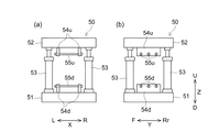
FIG. 1 is a front view schematically showing a
[単電池]
図3は、単電池10を模式的に示す三面図である。単電池10は、典型的には繰り返し充放電が可能な二次電池、例えば、リチウムイオン二次電池、ニッケル水素電池、電気二重層キャパシタ等である。なお、二次電池については、安全性を高めるために、電解質として可燃性の電解液を用いることなく、セラミックスやイオン伝導性ポリマー等からなる固体電解質を用いた全固体電池の実用化が進められている。以下、単電池10が全固体リチウムイオン二次電池である場合を例に説明するが、単電池10の構成はこれに限定されない。単電池10は、典型的には、図示しない正極と、負極と、固体電解質とからなる発電要素14と、電池ケース12とを備えている。一つの単電池10は、発電要素14を一つのみ備えていてもよいし、二つ以上備えていてもよい。この点において、本明細書でいう「単電池」とは、JIS D 0114:2000に規定される「単位電池」であり、本明細書でいう「発電要素」は、同規定の「単電池」であり得る。この発電要素14は、電池ケース12に収容されている。
[Battery]
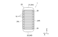
FIG. 3 is a three-view view schematically showing the
全固体電池は、正極活物質層と負極活物質層との間に固体電解質を層状に配置することで、発電要素14が構成される。これら固体電解質層および正・負の活物質層は、例えば、CVD法等によって緻密なバルク体として形成されていてもよいし、粉体状(粒子状)の電極構成材料をバインダで結着することで構成されていてもよい。全固体電池には電解液が存在しないことから、固体電解質層と正・負の活物質層との間の界面抵抗が電解液を備える液系二次電池よりも高い。これに加え、粉体材料を用いて製造される全固体電池については、固体電解質層および正・負の活物質層を構成する粒子間にも界面抵抗が発生する。そのため、全固体電池からなる電池パックに対しては、界面抵抗を低減することを目的として、液系二次電池の電池パックと比べて5〜10倍程度の高い拘束圧を印加したいという要求がある。後述するが、ここに開示される電池パック1は、従来よりも高い拘束圧を内在させて単電池10を拘束することができる。したがって、発電要素14としては、より高い拘束圧を加えることが求められる粉体状の電極構成材料を用いて形成されたものを好適に採用することができる。
In the all-solid-state battery, the
固体電解質層は、固体電解質材料を主体として含む。固体電解質材料としては、例えば、リチウムイオン伝導性を有するが、電子伝導性は示さない各種の化合物を好適に用いることができる。このような固体電解質材料としては、具体的には、例えば、Li2S−SiS2、LiI−Li2S−SiS2、LiI−Li2S−P2S5、LiI−Li2S−B2S3、Li3PO4−Li2S−Si2S、Li3PO4−Li2S−SiS2、LiPO4−Li2S−SiS、LiI−Li2S−P2O5、LiI−Li3PO4−P2S5、LiI−Li3PS4−LiBr、Li2S−P2S5、Li2S−P2S5−LiI−LiBrおよびLi2S−P2S5−GeS2等の非晶質硫化物、Li2O−B2O3−P2O5、Li2O−SiO2、Li2O−B2O3、およびLi2O−B2O3−ZnO等の非晶質酸化物、Li10GeP2S12等の結晶質硫化物、Li1.3Al0.3Ti0.7(PO4)3、Li1+x+yA1 xTi2-xSiyP3-yO12(A1は、AlまたはGa、0≦x≦0.4、0<y≦0.6)、[(A2 1/2Li1/2)1-zCz]TiO3(A2は、La、Pr、Nd、またはSm、CはSrまたはBa、0≦z≦0.5)、Li5La3Ta2O12、Li7La3Zr2O12、Li6BaLa2Ta2O12、およびLi3.6Si0.6P0.4O4等の結晶質酸化物、Li3PO(4-3/2w)Nw(w<1)等の結晶質酸窒化物、Li3N等の結晶質窒化物、ならびに、LiI、LiI−Al2O3、およびLi3N−LiI−LiOH等の結晶質ヨウ化物等が例示される。なかでも優れたリチウムイオン伝導性を有する点で、非晶質硫化物を好ましく用いることができる。 The solid electrolyte layer mainly contains a solid electrolyte material. As the solid electrolyte material, for example, various compounds having lithium ion conductivity but not electron conductivity can be preferably used. Such solid electrolyte material, specifically, for example, Li 2 S-SiS 2, LiI-Li 2 S-SiS 2, LiI-Li 2 S-P 2 S 5, LiI-Li 2 S-B 2 S 3, Li 3 PO 4 -Li 2 S-Si 2 S, Li 3 PO 4 -Li 2 S-SiS 2, LiPO 4 -Li 2 S-SiS, LiI-Li 2 S-P 2 O 5, LiI -Li 3 PO 4 -P 2 S 5 , LiI-Li 3 PS 4- LiBr, Li 2 SP 2 S 5 , Li 2 SP 2 S 5 -Li I-Li Br and Li 2 SP 2 S 5 -Amorphous sulfides such as GeS 2 , Li 2 O-B 2 O 3 -P 2 O 5 , Li 2 O-SiO 2 , Li 2 O-B 2 O 3 , and Li 2 O-B 2 O 3 -Amorphous oxides such as ZnO, crystalline sulfides such as Li 10 GeP 2 S 12 , Li 1.3 Al 0.3 Ti 0.7 (PO 4 ) 3 , Li 1 + x + y A 1 x Ti 2-x Si y P 3-y O 12 (A 1 is Al or Ga, 0 ≦ x ≦ 0.4, 0 <y ≦ 0.6), [(A 2 1/2 Li 1/2 ) 1-z C z ] TiO 3 (A 2 is La, Pr, Nd, or Sm, C is Sr or Ba, 0 ≦ z ≦ 0.5), Li 5 La 3 Ta 2 O 12 , Li 7 La 3 Zr 2 O 12 , Li Crystalline oxides such as 6 BaLa 2 Ta 2 O 12 and Li 3.6 Si 0.6 P 0.4 O 4 , crystalline acid nitrides such as Li 3 PO (4-3 / 2w) N w (w <1), Li crystalline nitride such as 3 N, and, LiI, LiI-Al 2 O 3, and Li 3 crystalline iodide such as N-LiI-LiOH and the like. Among them, amorphous sulfide can be preferably used because it has excellent lithium ion conductivity.
なお、固体電解質としては、リチウム塩を含むポリエチレンオキシド、ポリプロピレンオキシド、ポリフッ化ビニリデン、またはポリアクリロニトリル等の半固体のポリマー電解質も使用することができる。
また、本明細書において、「主体とする」とは、当該成分が50質量%以上含まれることを意味し、好ましくは60質量%以上、より好ましくは70質量%以上、例えば80質量%以上含まれる態様であり得る。
As the solid electrolyte, a semi-solid polymer electrolyte such as polyethylene oxide containing a lithium salt, polypropylene oxide, polyvinylidene fluoride, or polyacrylonitrile can also be used.
Further, in the present specification, "mainly" means that the component is contained in an amount of 50% by mass or more, preferably 60% by mass or more, more preferably 70% by mass or more, for example, 80% by mass or more. It can be an aspect of the above.
正極活物質層は、正極活物質を主体として含む。負極活物質層は、負極活物質を主体として含む。正極活物質および負極活物質としては、全固体電池の電極活物質として利用可能な各種の材料を用いることができる。例えば、リチウムイオンを吸蔵・放出することができる各種の化合物を好適に用いることができる。これら正極活物質と負極活物質とに明確な制限はなく、例えば、二種類の活物質材料の充放電電位を比較して、充放電電位が相対的に貴な電位を示すものを正極に、卑な電位を示すものを負極に用いることができる。 The positive electrode active material layer mainly contains the positive electrode active material. The negative electrode active material layer mainly contains the negative electrode active material. As the positive electrode active material and the negative electrode active material, various materials that can be used as the electrode active material of the all-solid-state battery can be used. For example, various compounds capable of occluding and releasing lithium ions can be preferably used. There is no clear limitation on these positive electrode active materials and negative electrode active materials. Those showing a low potential can be used for the negative electrode.
このような活物質材料としては、例えば、コバルト酸リチウム(例えば、LiCoO2)、ニッケル酸リチウム(例えば、LiNiO2)、Li1+xCo1/3Ni1/3Mn1/3O2(xは0≦x<1を満たす)等の層状岩塩型リチウム遷移金属酸化物、マンガン酸リチウム(例えば、LiMn2O4)、Li1+xMn2-x-yM1 yO4(M1は、Al、Mg、Ti、Co、Fe、Ni、およびZnから選ばれる1種以上の金属元素であり、x,yは独立して0≦x,y≦1を満たす)で表される組成の異種元素置換Li−Mnスピネル等のスピネル型リチウム遷移金属酸化物、チタン酸リチウム(例えば、LixTiOy、x,yは独立して0≦x,y≦1を満たす)、リン酸金属リチウム(例えば、LiM2PO4、M2はFe、Mn、Co、またはNi)、酸化バナジウム(例えば、V2O5)および酸化モリブデン(例えば、MoO3)等の酸化物、硫化チタン(例えば、TiS2)、グラファイトおよびハードカーボン等の炭素材料、リチウムコバルト窒化物(例えば、LiCoN)、リチウムシリコン酸化物(例えば、LixSiyOz、x,y,zは独立して0≦x,y,z≦1を満たす)、リチウム金属(Li)、シリコン(Si)およびスズ(Sn)ならびにこれらの酸化物(例えば、SiO、SnO2)、リチウム合金(例えば、LiM3、M3は、C、Sn、Si、Al、Ge、Sb、PbまたはP)、リチウム貯蔵性金属間化合物(例えば、MgxM4やM5 ySb、M4はSn、Ge、またはSb、M5はIn、Cu、またはMn)、ならびに、これらの誘導体や複合体が挙げられる。 Examples of such an active material include lithium cobaltate (for example, LiCoO 2 ), lithium nickelate (for example, LiNiO 2 ), and Li 1 + x Co 1/3 Ni 1/3 Mn 1/3 O 2 (for example, LiCoO 2). Layered rock salt type lithium transition metal oxide such as x satisfies 0 ≦ x <1), lithium manganate (for example, LiMn 2 O 4 ), Li 1 + x Mn 2-xy M 1 y O 4 (M 1 is , Al, Mg, Ti, Co, Fe, Ni, and Zn, which are one or more metal elements, and x and y independently satisfy 0≤x, y≤1). Spinel-type lithium transition metal oxides such as dissimilar element-substituted Li-Mn spinels, lithium titanates (for example, Li x TiO y , x, y independently satisfy 0 ≦ x, y ≦ 1), lithium metal phosphates. (For example, LiM 2 PO 4 , M 2 is Fe, Mn, Co, or Ni), oxides such as vanadium oxide (eg V 2 O 5 ) and molybdenum oxide (eg MoO 3 ), titanium sulfide (eg MoO 3). TiS 2 ), carbon materials such as graphite and hard carbon, lithium cobalt nitride (eg LiCoN), lithium silicon oxide (eg Li x S y O z , x, y, z independently 0 ≦ x, (Satisfying y, z ≦ 1), lithium metal (Li), silicon (Si) and tin (Sn) and their oxides (eg, SiO, SnO 2 ), lithium alloys (eg, LiM 3 , M 3) C, Sn, Si, Al, Ge, Sb, Pb or P), lithium-storing metal-to-metal compounds (eg, Mg x M 4 and M 5 y Sb, M 4 is Sn, Ge, or Sb, M 5 is In. , Cu, or Mn), as well as derivatives and complexes thereof.
なお、電極活物質は、リチウムイオンの吸蔵・放出に伴って体積膨張・収縮を生じ得る。ここで、リチウムイオンの吸蔵・放出に伴う体積変化率の大きな材料からなる活物質層は、割れや剥離が生じやすく、界面抵抗が高まりやすい。その一方で、ここに開示される電池パック1は、上述の通り従来よりも高い拘束圧を内在させて構成することができるため、活物質層の割れや剥離等による界面抵抗の上昇を好適に抑制し得る。かかる観点から、ここに開示される技術によると、電極活物質として、体積膨張率の大きな材料であっても好ましく採用することができる。このような電極活物質としては、例えば、炭素材料や、リチウムと合金を形成する金属材料が挙げられる。なかでも、理論容量の高いシリコンおよびシリコン合金、リチウムおよびリチウム合金、スズおよびスズ合金等の金属材料を負極活物質として好ましく用いることができる。
The electrode active material may undergo volume expansion / contraction with the occlusion / release of lithium ions. Here, the active material layer made of a material having a large volume change rate due to occlusion / release of lithium ions is liable to crack or peel off, and the interfacial resistance is liable to increase. On the other hand, since the
また、正・負の活物質層は、層内でのリチウムイオン伝導性を高めるために、活物質材料の一部を上記の固体電解質材料に置き換えてもよい。この場合、活物質層に含有させる固体電解質材料の割合は、活物質材料と固体電解質材料の合計を100質量%としたとき、例えば、60質量%以下とすることができ、50質量%以下が好ましく、40質量%以下がより好ましい。また、置き換えするときの固体電解質材料の割合は、10質量%以上が適切であり、20質量%以上が好ましく、30質量%以上がより好ましい。このような活物質材料と固体電解質材料との置き換えをする場合、正・負の物質層は、活物質材料と固体電解質材料とを主体として構成することができる。 Further, in the positive and negative active material layers, a part of the active material may be replaced with the above-mentioned solid electrolyte material in order to enhance the lithium ion conductivity in the layer. In this case, the ratio of the solid electrolyte material contained in the active material layer can be, for example, 60% by mass or less, and 50% by mass or less, when the total of the active material and the solid electrolyte material is 100% by mass. It is preferably 40% by mass or less, more preferably 40% by mass or less. Further, the ratio of the solid electrolyte material at the time of replacement is appropriately 10% by mass or more, preferably 20% by mass or more, and more preferably 30% by mass or more. When the active material material and the solid electrolyte material are replaced with each other, the positive and negative material layers can be mainly composed of the active material material and the solid electrolyte material.
なお、より電位の高い正極活物質層に硫化物からなる固体電解質を含有させる場合、正極活物質と固体電解質との界面に高抵抗の反応層が形成されて、界面抵抗が高く虞がある。したがって、このような事象を抑制するために、正極活物質粒子はリチウムイオン伝導性を有する結晶性酸化物で被覆しておくことができる。正極活物質を被覆するリチウムイオン伝導性酸化物としては、例えば、一般式LixA3Oyで表される酸化物を挙げることができる。ここで式中のA3は、B、C、Al、Si、P、S、Ti、Zr、Nb、Mo、TaまたはWであり、xおよびyは正の数である。リチウムイオン伝導性酸化物としては、具体的には、Li3BO3、LiBO2、Li2CO3、LiAlO2、Li4SiO4、Li2SiO3、Li3PO4、Li2SO4、Li2TiO3、Li4Ti5O12、Li2Ti2O5、Li2ZrO3、LiNbO3、Li2MoO4、Li2WO4等を例示することができる。また、リチウムイオン伝導性酸化物は、例えばLi4SiO4−Li3BO3、Li4SiO4−Li3PO4等のように、上記リチウムイオン伝導性酸化物の任意の組み合わせからなる複合酸化物であってもよい。
When a solid electrolyte made of sulfide is contained in the positive electrode active material layer having a higher potential, a high resistance reaction layer is formed at the interface between the positive electrode active material and the solid electrolyte, and the interface resistance may be high. Therefore, in order to suppress such an event, the positive electrode active material particles can be coated with a crystalline oxide having lithium ion conductivity. Examples of the lithium-ion conductive oxide covering the positive electrode active material, for example, a
正極活物質粒子の表面をイオン伝導性酸化物で被覆する場合、イオン伝導性酸化物は、正極活物質の少なくとも一部を被覆していればよく、正極活物質粒子の表面の全体を被覆していてもよい。正極活物質粒子を被覆するイオン伝導性酸化物の厚さは、例えば、0.1nm以上が好ましく、1nm以上がより好ましい。また、イオン伝導性酸化物の厚さは、例えば、100nm以下であることが好ましく、20nm以下がより好ましい。なお、イオン伝導性酸化物の厚さは、例えば、透過型電子顕微鏡(TEM)等の電子顕微鏡を用いて測定することができる。 When the surface of the positive electrode active material particles is coated with the ionic conductive oxide, the ionic conductive oxide need only cover at least a part of the positive electrode active material, and covers the entire surface of the positive electrode active material particles. May be. The thickness of the ion conductive oxide covering the positive electrode active material particles is, for example, preferably 0.1 nm or more, and more preferably 1 nm or more. The thickness of the ion conductive oxide is preferably, for example, 100 nm or less, more preferably 20 nm or less. The thickness of the ionic conductive oxide can be measured using, for example, an electron microscope such as a transmission electron microscope (TEM).
正・負の活物質層は、必要に応じて電子伝導性を高めるための導電材を含んでもよい。導電材は特に制限されるものではなく、例えば、黒鉛や、アセチレンブラック(AB)、ケッチェンブラック(KB)等のカーボンブラック、気相成長カーボン繊維(VGCF)、カーボンナノチューブ、カーボンナノファイバー、その他の炭素材料を好適に用いることができる。このような導電材は、電極活物質層の総量を100質量%としたとき、例えば、1質量%以上であり、1〜12質量%の範囲内であってもよく、2〜10質量%の範囲内であってもよい。 The positive and negative active material layers may contain a conductive material for enhancing electron conductivity, if necessary. The conductive material is not particularly limited, and is not particularly limited, for example, graphite, carbon black such as acetylene black (AB) and Ketjen black (KB), gas phase growth carbon fiber (VGCF), carbon nanotube, carbon nanofiber, and the like. Carbon material can be preferably used. When the total amount of the electrode active material layer is 100% by mass, such a conductive material is, for example, 1% by mass or more, may be in the range of 1 to 12% by mass, and 2 to 10% by mass. It may be within the range.
なお、発電要素14を粉体状の電極構成材料を用いて形成する場合、その平均粒子径(D50)は特に限定されず、例えば以下の大きさのものを用いることが好適例として挙げられる。すなわち、固体電解質層を粉体材料で構成する場合、平均粒子径は、例えば、約0.1μm以上であり、0.4μm以上が好ましい。また、固体電解質材料の平均粒子径は、例えば50μm以下とすることができ、5μm以下が好ましい。電極活物質層を粉体材料で構成する場合、平均粒子径は、例えば0.1μm以上であり、0.5μm以上であってよい。一方、平均粒子径は、例えば50μm以下であり、5μm以下であってもよい。粉体材料を造粒粉体の形態に加工して用いる場合は、一次粒子としての平均粒子径が上記範囲にあるとよい。
なお、本明細書における平均粒子径は、レーザー回折・光散乱式の粒度分布計を用いて測定される体積基準の粒度分布において、累積50%に相当する粒子径である。なお、平均粒子径が1μm以下となるより微細な粉体については、動的光散乱(Dynamic light scattering:DLS)法による測定値を採用してもよい。
When the
The average particle size in the present specification is a particle size corresponding to a cumulative 50% in the volume-based particle size distribution measured by using a laser diffraction / light scattering type particle size distribution meter. For finer powders having an average particle size of 1 μm or less, the measured values by the Dynamic light scattering (DLS) method may be adopted.
また、粉体状の電極構成材料を結着するバインダとしては特に制限されず、例えば、結着性を有する各種の有機化合物を用いることができる。このようなバインダとしては、例えば、ポリテトラフルオロエチレン、ポリトリフルオロエチレン、ポリエチレン、セルロース樹脂、アクリル樹脂、ビニル樹脂、ニトリルゴム、ポリブタジエンゴム、ブチルゴム、ポリスチレン、スチレンブタジエンゴム、スチレンブタジエンラテックス、多硫化ゴム、アクリロニトリルブタジエンゴム、ポリフッ化ビニル、ポリフッ化ビニリデン(PVDF)、フッ素ゴム等が挙げられる。バインダは、上記のいずれか1種を単独で用いてもよいし、2種以上を組み合わせて用いてもよい。 Further, the binder for binding the powdery electrode constituent material is not particularly limited, and for example, various organic compounds having binding properties can be used. Examples of such a binder include polytetrafluoroethylene, polytrifluoroethylene, polyethylene, cellulose resin, acrylic resin, vinyl resin, nitrile rubber, polybutadiene rubber, butyl rubber, polystyrene, styrene butadiene rubber, styrene butadiene latex, and polysulfide. Examples thereof include rubber, acrylonitrile butadiene rubber, polyvinyl fluoride, polyvinylidene fluoride (PVDF), and fluororubber. As the binder, any one of the above may be used alone, or two or more thereof may be used in combination.
上記発電要素14は、集電体を備えることで外部負荷に電力を取り出すことができる。集電体の形状は特に制限されず、例えば、箔状、板状、メッシュ状等とすることが好適である。そして例えば、集電体の表面(片面または両面)に活物質層を備えるとよい。このような集電体としては、電子伝導性に優れ、使用する活物質の充放電電位において変質し難い各種の材料を用いることができる。例えば、集電体材料としては、アルミニウム、銅、ニッケル、鉄、チタン、およびこれらの合金(例えば、アルミニウム合金、ステンレス鋼)、ならびにカーボン等を挙げることができる。集電体の厚みは電極体の寸法等にもよるため特に制限されず、例えば、5μm以上500μm以下が好ましく、10μm以上100μm以下程度がより好ましい。
The
単電池10が発電要素14を一つのみ含む場合、例えば集電体の片面に活物質層を備えるとよい。この場合、例えば、正極集電体の片面に正極活物質層を備えた正極と、負極集電体の片面に負極活物質層を備えた負極とを、活物質層が対向する向きで固体電解質層を介して重ね合わせることで発電要素14を構築することができる。また、単電池10が発電要素14を二つ以上含む場合、例えば集電体の両面に活物質層を備えるとよい。この場合、例えば、正極集電体の両面に正極活物質層を備えた正極と、負極集電体の両面に負極活物質層を備えた負極と、を複数枚ずつ用意し、正・負の活物質層の間を固体電解質層で絶縁して交互に重ね合わせることで、複数の発電要素14を構築することができる。
When the
全固体電池には電解液が存在しないことから、固体電解質層と正・負の活物質層との間の界面抵抗が高くなる。これに加え、例えば、粉体状の材料を用いて製造された全固体電池では、固体電解質層および正・負の活物質層内においても粒子間の界面、空隙等によって界面抵抗が高められる。このような界面抵抗を低減するためには、正極活物質層、固体電解質層および負極活物質層を積層した発電要素14を、その積層方向に沿って圧縮する方向に押圧し、各層間および各層内の空隙を低減するなどして充填密度を高めることが効果的である。
Since there is no electrolytic solution in the all-solid-state battery, the interfacial resistance between the solid electrolyte layer and the positive / negative active material layer becomes high. In addition to this, for example, in an all-solid-state battery manufactured using a powdery material, the interface resistance is increased by the interface between particles, voids, etc. even in the solid electrolyte layer and the positive / negative active material layer. In order to reduce such interfacial resistance, the
そこで本実施形態では、電池ケース12を軟質の金属ラミネートフィルムによって構成している。電池ケース12は、発電要素14を収容する外装材である。金属ラミネートフィルムは、例えば、アルミニウムや銅等の軽量で比較的柔らかな金属箔と、ポリプロピレン(PP)等の絶縁性の熱可塑性樹脂シートとが貼り合わされて構成されており、変形の自由度が高い。そのため、金属ラミネートフィルムからなる電池ケース12は、金属缶からなる電池ケースを採用した場合に比べて、拘束機構20による拘束圧を発電要素14に効果的に負荷することができる。また電池ケース12を金属ラミネートフィルムにより構成することで、単電池10の薄型化や軽量化を図ることができる。電池ケース12は、例えば、金属ラミネートフィルム(典型的には、アルミ/PPラミネートシート)からなるバッグに発電要素14を収容したのち、バッグを熱溶着して密閉することで、発電要素14を外部環境から遮蔽することができる。このとき、電池ケース12の外部には、外部接続端子16としての正極端子16aと負極端子16bとが引き出されている。正極端子16aは、発電要素14の正極集電体に電気的に接続されており、負極端子16bは発電要素14の負極集電体に電気的に接続されている。ただし、電池ケース12は、金属ラミネートフィルム製のものに限定されず、例えば、アルミニウム、スチール、高強度プラスチック等からなる外形が角型や円筒型等の容器であってもよい。
Therefore, in the present embodiment, the
単電池10は、図3に示すように、平面視で長手方向Yに長い長方形の板状の発電要素14を含む。発電要素14は、平面視で長方形の正極活物質層、固体電解質層、および負極活物質層が、厚み方向に積層されている。発電要素14を収容する電池ケース12もまた、平面視で長手方向Yに長い長方形である。電池ケース12の発電要素14が存在しない部位は、金属ラミネートフィルムが溶着されて、正面視および側面視における厚み(配列方向Zの寸法)が薄い。また、電池ケース12の長手方向Yの前方Fの端部には、外部接続端子16が突出するように配設されている。外部接続端子16の正極端子16aと負極端子16bとは、幅方向Xに離間して配置されている。このような単電池10は、発電要素14の厚み方向が配列方向Zとなるように複数のものが配列して積層されている。これにより、配列された複数の単電池からなる電池スタックが構成される。
As shown in FIG. 3, the
[拘束機構]
拘束機構20は、一対のエンドプレート部21、22と、拘束フープ部24と、を備えている。エンドプレート部21、22は、単電池10の発電要素14に対して拘束圧を均等に加えるための板状の部材である。拘束フープ部24は、エンドプレート部21、22間に加えられた拘束圧を、エンドプレート部21、22間に内在させて維持するための部材である。
[Restriction mechanism]
The
一対のエンドプレート部21、22は、配列された複数個の単電池10を配列方向Zに挟むように、その両端に配置されている。第一エンドプレート部21は、配列された単電池10の配列方向Zの第一方向Z1(上方U)の端部に配置されている。第二エンドプレート部22は、配列された単電池10の配列方向Zの第二方向Z2(下方D)の端部に配置されている。エンドプレート部21、22は、互いが平行となるように、配列方向Zに対して直交するように配置されている。エンドプレート部21、22は、幅方向Xの寸法が単電池10の電池ケース12の寸法よりも一回り大きい。エンドプレート部21、22は、長手方向Yの寸法が単電池10の発電要素14の寸法よりも一回り大きい。エンドプレート部21、22は、単電池10の発電要素14よりも一回り大きく構成されている。また、第一エンドプレート部21は、正面視で、上方Uの幅方向Xの左右の角部が丸く曲面化されている。第二エンドプレート部22は、正面視で下方Dの幅方向Xの左右の角部が丸く曲面化されている。
The pair of
拘束フープ部24は、環状のベルト形状を有している。拘束フープ部24は、上方Uに第一エンドプレート部21の上方Uの表面に沿って配置される上面部24Uを備えている。拘束フープ部24は、下方Dに第二エンドプレート部22の下方Dの表面に沿って配置される下面部24Dを備えている。拘束フープ部24は、第一エンドプレート部21の左端から第二エンドプレート部22の左端に至るように、上面部24Uと下面部24Dとを配列方向Zに沿って連続的に繋ぐ平坦な左側面部24Lを左方Lに備えている。拘束フープ部24は、第一エンドプレート部21の右端から第二エンドプレート部22の右端に至るように、上面部24Uと下面部24Dとを配列方向Zに沿って連続的に繋ぐ平坦な右側面部24Rを右方Rに備えている。このことにより、拘束フープ部24は、配列方向Zと幅方向Xとに平行な断面において、第一エンドプレート部21と配列された複数個の単電池10と第二エンドプレート部22とからなるスタックを、その外周に沿って環状に取り囲んでいる。本実施形態において、拘束機構20は、エンドプレート部21、22の長手方向Yの前方Fと後方Rrとに一つずつ、計二つの拘束フープ部24を備えている。なお、上面部24Uおよび下面部24Dは、ここに開示される電池パック1における第一支持部と第二支持部の一例である。
The
エンドプレート部21、22には、図4(e)に示すように、厚み方向の中央付近に、幅方向Xに貫通する治具穴21a、22aがそれぞれ設けられている。この治具穴21a、22aは、後述する電池パック1の製造および解体に際して使用する取付用治具55u、55d(図6参照)を、エンドプレート部21、22に貫通挿入するための穴である。治具穴21a、22aは、長手方向Yの前方Fと後方Rrと中央とに一つずつ、計三つが設けられている。治具穴21a、22aは、二つの拘束フープ部24の両端とその中間とに配置されるように、長手方向Yに沿って等間隔で設けられている。ただし、治具穴21a、22aの数、配置等はこれに制限されない。
As shown in FIG. 4 (e), the
拘束フープ部24は、環状に閉じられていることにより、エンドプレート部21、22の離間距離を規制する。そして拘束フープ部24の左側面部24Lおよび右側面部24Rの配列方向Zの寸法は、配列された状態で拘束されている複数個の単電池10の配列方向Zの寸法に等しい。このことにより、拘束フープ部24は、単電池10に付与する拘束圧が所定の大きさとなるように、左側面部24Lおよび右側面部24Rの配列方向Zの寸法が決定される。例えば、拘束フープ部24は、左側面部24Lおよび右側面部24Rの配列方向Zの寸法を、無負荷状態の電池スタックの配列方向Zの寸法よりも小さくすることで、単電池10に対する拘束圧を内在させて、電池スタックを拘束することができる。そしてまた、拘束フープ部24は、電池スタックからの拘束圧に対する反力によって、降伏に至らないように、左側面部24Lおよび右側面部24Rの配列方向Zの寸法が決定されている。換言すると、例えば、拘束フープ部24は、配列方向Zに沿う引張方向に弾性領域で変形されていることにより、単電池10に対して圧縮する方向へ作用する拘束圧を高く内在させることができる。単電池10に付与された拘束圧は、拘束フープ部24によって維持される。拘束フープ部24は、例えば、単電池10に対して0.1〜110MPa程度のこれまでにない高い拘束圧を維持できるように構成されている。拘束圧は、例えば、1MPa以上、10MPa以上、30MPa以上、50MPa以上、80MPa以上、100MPa以上であってよい。単電池10の長側面に対して加える荷重は、例えば、2t以上、5t以上、8t以上、10t以上と、拘束フープ部24の引張強度に応じてこれまでにない値にまで高めることができる。なお、エンドプレート部21、22の角部(配列方向Zの単電池10とは反対側となる外側の表面から幅方向Xの側面に至る角部)は曲面化されているため、拘束圧が拘束フープ部24に局所的に作用することが抑制されている。
The
エンドプレート部21、22は、配列方向Zに沿って単電池10に加えられる拘束圧によって変形されない各種の材料によって構成することができる。そのようなエンドプレート部21、22の構成材料としては、例えば、アルミニウムまたはアルミニウム合金、鉄または各種の鋼材(例えば構造用鋼)、高強度合金等に代表される金属材料、強化プラスチック、エンジニアプラスチック等の樹脂材料、ファインセラミックス、炭素繊維材料等の曲げ強度の高い無機材料、ならびに、炭素繊維強化プラスチック(CFRP)等のこれらの複合材料等が挙げられる。また、拘束フープ部24は、配列方向Zの拘束力に対する単電池10からの反力によって、降伏点を越えるような塑性変形(延伸)を生じたり破断したりしない引張強度を有する各種の材料によって構成することができる。そのようなフープ構成材料としては、例えば、例えば、アルミまたはアルミ合金、鉄または各種の鋼材(例えば構造用鋼)、高強度合金等に代表される金属材料、強化プラスチック、エンジニアプラスチック等の樹脂材料、炭素繊維材料等の引張強度の高い無機材料、ならびに、炭素繊維強化プラスチック(CFRP)等のこれらの複合材料等が挙げられる。
The
なお、拘束フープ部24は、一例として、図4(a)および(d)に示すように、単一の材料からなる継ぎ目の無い環状構造を有している。このような拘束フープ部24は、従来公知の各種の手法を利用して製造することができる。フープ構成材料が樹脂材料の場合、例えば、射出成形法、キャスティング法等によって、継ぎ目の無い管状の樹脂フープを得ることができる。フープ構成材料が金属材料の場合、例えば、切削加工法や、遠心鋳造法、穿孔圧延等によって継ぎ目の無い管状の金属フープを得ることができる。また、フープ構成材料が樹脂材料や金属材料の場合は、例えば、シート状のフープ構成材料を拘束フープ部の断面形状に対応する管状に曲げ加工したのち、端部を固相接合することで、管状に閉じた樹脂フープまたは金属フープを得ることができる。さらに、フープ構成材料がCFRPの場合、例えば、炭素繊維とエポキシ樹脂等の母相樹脂材料とから構成されるプリプレグシートを拘束フープ部の断面形状に対応する金型に環状に巻き付け、加熱一体化させることで、管状のCFRPフープを得ることができる。これらの管状のフープは、所望のフープ幅に切り出すことで、拘束フープ部24とすることができる。拘束フープ部24の幅を広くすることで、拘束フープ部24は、より高い拘束圧を内包することができる。
As an example, the
その一方で、拘束フープ部24は、一例として、図4(b)および(c)に示すように、継ぎ目のある環状構造を有していてもよい。拘束フープ部24が継ぎ目を有する場合、拘束フープ部24の左側面部24Lと右側面部24Rとで引張強度を均等にするために、継ぎ目は左側面部24Lと右側面部24Rとのそれぞれに設けられていることが好ましい。このような拘束フープ部24は、例えば、正面視でU字型(半環状)となる2つの部材の端部を互いに重ねて接合することで形成することができる。接合方法としては、一例として、図4(b)に示すように、接着剤等の接合材を介して接合する方法と、図4(c)に示すように、接合材を使用することなく、レーザ溶接法、抵抗溶接法、固相接合法等による直接的に接合する方法が挙げられる。
On the other hand, the
ここで、例えば2つのU字型部材を重ねて一つの環に接合する場合、拘束フープ部24に作用する引張応力のベクトルが、U字型の一の部材と他の部材とで幅方向Xに僅かにずれる。単電池10を拘束するための拘束圧が小さいときは、このような引張応力のベクトルのずれは問題にならないが、拘束圧がこれまでに無く大きく(典型的には、従来の約5倍以上、例えば約10倍以上)なると、拘束フープ部24は引張応力のベクトルのずれを矯正する方向に接合部を変形する場合がある。その結果、拘束フープ部24に作用する引張応力が、例えば、接合部の上端や下端に局所的に集中し易く、U字型の一の部材と他の部材とが結合部の上端や下端を起点として破断する虞がある。このような観点において、拘束フープ部24は、図4(a)および(d)に示したように、継ぎ目の無い環状であることがより好ましい。
Here, for example, when two U-shaped members are overlapped and joined to one ring, the vector of the tensile stress acting on the
拘束フープ部24の長手方向Yに対応するフープ幅方向の寸法は、特に制限されない。例えば、一または複数の拘束フープ部24のフープ幅方向の寸法の合計は、発電要素14の長手方向Y(すなわちフープ幅方向)の寸法の1/4以上であるとよい。例えば、拘束機構20に拘束フープ部24が2つ備えられている場合、それぞれの拘束フープ部24のフープ幅方向の寸法は、発電要素のフープ幅方向の寸法の1/8以上であるとよい。これにより、拘束機構20によって複数の単電池10を安定的に拘束することができる。拘束フープ部24のフープ幅方向の寸法の合計は、発電要素の長手方向Yの寸法の1/3以上であってよく、1/2以上が好ましく、2/3以上がより好ましく、3/4以上であってよく、5/6以上としてもよい。拘束フープ部24のフープ幅方向の寸法の合計は、組付け精度とコスト低減との兼ね合いから、例えば、発電要素14の長手方向Yの寸法の1.1以下とすることができ、1以下であってよく、0.9以下としてもよい。なお、拘束フープ部24のフープ幅の寸法が、発電要素14の長手方向Yの寸法の1/2以上の幅広である場合、拘束機構20は、このような幅広の拘束フープ部24を一つのみ備えていてもよい。このような構成によっても、拘束機構20によって複数の単電池10を安定的に拘束することができる。
The dimension in the hoop width direction corresponding to the longitudinal direction Y of the
上記構成によると、拘束機構20は、環状の拘束フープ部24によって一対のエンドプレート部21、22の外周を取り囲むことにより、複数の単電池10を配列方向Zに沿って圧縮する方向に拘束している。この拘束機構20は、締結具等の別部材を用いて拘束フープ部24を固定していない。これにより、拘束機構20においては、締結具が塑性変形したり破損したりすることがなく、単電池10の拘束が緩むことを抑制し、長期にわたって単電池10に必要な拘束圧を維持することができる。このことは、使用時に振動や衝撃等が発生する用途の電池パック1等において特に効果を発揮することができる。また、このような効果は、単電池10が界面抵抗の低減のために圧縮応力の付与が望まれる全固体電池であったり、活物質として充放電に伴う体積膨張率の大きな材料を用いている場合等の、これまでに無い大きな拘束圧を内在することが求められる電池パック1に対して特に好適に発現される。
According to the above configuration, the
[製造方法1]
以上の構成の電池パック1は、例えば図5に示すように、以下の製造工程S1〜S5に従うことで好適に製造することができる。
(S1)電池スタックSAを用意する工程。
(S2)第一エンドプレート部21、第二エンドプレート部22および拘束フープ部24を配置する工程。
(S3)拘束フープ部24を延伸させる工程。
(S4)エンドプレート部21、22の間に電池スタックSAを挿入する工程。
(S5)複数の単電池10を拘束する工程。
[Manufacturing method 1]
As shown in FIG. 5, for example, the
(S1) A step of preparing a battery stack SA.
(S2) A step of arranging the first
(S3) A step of stretching the
(S4) A step of inserting the battery stack SA between the
(S5) A step of restraining a plurality of
そしてこのような電池パック1の製造方法は、例えば、図6に示す電池パック組付け装置50を使用することによって、好適に実施することができる。すなわち、この電池パック組付け装置50は、大まかな構成として、ベース部51と、天板部52と、4つの油圧式ピストン53とを備えている。油圧式ピストン53は、中心軸が鉛直方向に沿うように、ベース部51の四隅に立設されている。鉛直方向は、電池パック1の配列方向Zに一致する。油圧式ピストン53は、天板部52の四隅を下方Dから固定的に支持している。油圧式ピストン53は、天板部52を鉛直方向に沿って上下に移動させることにより、ベース部51と天板部52との間の距離を任意に変更することができるように構成されている。
Then, such a method for manufacturing the
天板部52の下面には、第一エンドプレート部21を天板部52に固定するための一対のエンドプレートホルダ54uが対向するように設けられている。ベース部51の上面には、第二エンドプレート部22をベース部51に固定するための一対のエンドプレートホルダ54dが対向するように設けられている。一対のエンドプレートホルダ54u、54dには、それぞれ幅方向Xに沿う同一軸上に図示しない貫通孔が設けられている。そしてエンドプレートホルダ54u、54dの対向する貫通孔には、ボルト・ナット型の取付用治具55u、55dが貫通孔を連通するように着脱自在に備えられている。本実施形態の電池パック組付け装置50には、エンドプレートホルダ54u、54dに三つの貫通孔が長手方向Yに沿って等間隔で設けられている。エンドプレートホルダ54u、54dに設けられた貫通孔と、エンドプレート部21、22に設けられた治具穴21a、22aとは位置が対応している。
A pair of
まず製造工程S1では、図5に示すように、複数の単電池10を厚み方向が配列方向Zとなるようにして配列する。これによって、複数の単電池10が配列された電池スタックSAを用意する。ここでは、圧縮応力を負荷する対象である発電要素14が配列方向Zに揃うように、複数の単電池10を幅方向Xと長手方向Yとを一致させて積層する。用意された電池スタックSAの配列方向Zの寸法はB1である。電池スタックSAは、後工程のエンドプレート部21、22間への挿入の前に、配列方向Zに押圧することで、予備的に圧縮しておいてもよい。
First, in the manufacturing process S1, as shown in FIG. 5, a plurality of
製造工程S2では、拘束機構20のうちの第一エンドプレート部21と第二エンドプレート部22とを配列方向Zに沿って離間して配置し、第一エンドプレート部21と第二エンドプレート部22とを配列方向Zに平行な面で囲むように環状の拘束フープ部24を配置する。このとき、予め第一エンドプレート部21を拘束フープ部24の環の中に挿入した状態で、第一エンドプレート部21を電池パック組付け装置50のエンドプレートホルダ54uに固定するとよい。エンドプレートホルダ54uへの固定に際しては、第一エンドプレート部21を、一対のエンドプレートホルダ54uの間に治具穴21aの位置と貫通穴の位置とが同軸上に並ぶように配置し、治具穴21aと貫通穴とに取付用治具55uを挿入してナットで固定するとよい。同様に、第二エンドプレート部22については、予め第二エンドプレート部22を拘束フープ部24の環の中に挿入した状態で、第二エンドプレート部22をベース部51に固定するとよい。エンドプレートホルダ54dへの固定に際しては、第二エンドプレート部22を一対のエンドプレートホルダ54dの間に、治具穴22aの位置と貫通穴の位置とが同軸上に並ぶように配置し、治具穴22aと貫通穴とに取付用治具55dを挿入してナットで固定するとよい。これにより、拘束機構20を電池パック組付け装置50にセットすることができる。ここで、拘束フープ部24の左側面部24Lおよび右側面部24Rの配列方向Zに沿う寸法はA1である。また、第一エンドプレート部21と第二エンドプレート部22との離間距離もA1である。寸法A1と寸法B1とは、A1<B1を満たす。寸法A1は、電池パック1において電池スタックSAが所定の拘束圧で圧縮されたときの寸法に概ね一致するように決定される。
In the manufacturing process S2, the first
製造工程S3では、第一エンドプレート部21を配列方向Zの第二エンドプレート部22とは反対側の第一方向Z1に相対的に変位させる。変位の寸法は、第一エンドプレート部21と第二エンドプレート部22との離間距離が、電池スタックSAの配列方向Zの寸法B1と同じかそれ以上となるように調整するとよい。また、第一エンドプレート部21の変位には、電池パック組付け装置50の油圧式ピストン53を駆動させるとよい。これにより、拘束フープ部24を配列方向Zに延伸させることができる。しかしながら、第一エンドプレート部21の変位の寸法は、拘束フープ部24が弾性領域で伸延される範囲に限定される。換言すると、第一エンドプレート部21は、拘束フープ部24が延伸により降伏変形しないように変位量が決定される。また、電池スタックSAの配列方向Zの寸法B1は、拘束フープ部24の左右の側面部24L、24Rの配列方向Zに沿う寸法A1が降伏することなく寸法B1となり得るように決定される。ここに開示される電池パック組付け装置50では、第一エンドプレート部21を変位させるために、4つの油圧式ピストン53を使用している。このことによって、引張強度の高い拘束フープ部24の延伸を高精度に制御することが可能である。
In the manufacturing process S3, the first
製造工程S4では、変位させた第一エンドプレート部21と第二エンドプレート部22との間に、電池スタックSAを挿入する。拘束フープ部24は、例えば、長手方向Yに直交する面において環を為す様に配置されている。したがって、電池スタックSAは、例えば、延伸された拘束フープ部24の長手方向Yの後方Rrに配置しておいたものを、前方Fにスライドさせることで第一エンドプレート部21と第二エンドプレート部22との間に挿入するとよい。これにより、スムースに電池スタックSAを拘束機構20に挿入することができる。
In the manufacturing process S4, between the first
製造工程S5では、第一エンドプレート部21の変位を解除する。例えば、4つの油圧式ピストン53の圧を開放することで、第一エンドプレート部21の変位を維持する力を解除することができる。これにより、伸延されていた拘束フープ部24は、元の寸法A1に戻ろうとして弾性収縮する。その結果、第一エンドプレート部21は、第二エンドプレート部22の側に相対的に変位する。このことにより、第一エンドプレート部21、第二エンドプレート部22および拘束フープ部24によって、複数の単電池10に対して配列方向Zに沿って圧縮する方向に荷重を負荷することができる。その結果、複数の単電池10を配列状態で拘束することができる。油圧式ピストン53の圧を開放した後は、エンドプレートホルダ54u、54dから取付用治具55u、55dを外すことで、電池パック1を得ることができる。
In the manufacturing process S5, the displacement of the first
なお、ここに開示される構成の電池パック1を、例えば従来の電池パックの製造方法と同様の手法によって製造しようとすると、さまざまな不都合が生じ得る。例えば、図13に示されるように、従来の電池パック101においては、複数の単電池110からなる電池スタックを一対のエンドプレート部121,122で挟み、所定の圧縮応力で圧縮した状態で、従来のコの字型の拘束バンド124をエンドプレート部121,122に固定している。ここで、従来のコの字型の拘束バンド124であれば、エンドプレート部121,122のほぼ全面を均一に押圧して単電池110を圧縮しながら、エンドプレート部121,122の端部に拘束バンド124の装着スペースを確保することができる。しかしながら、拘束バンド124に代えて、環状の拘束フープ部24を取り付けるようとすると、拘束フープ部24はエンドプレート部21,22の幅方向Xにわたるように装着する必要があるため、装着スペースを確保することが困難となる。例えば、エンドプレート部21,22の長手方向Yの両端部を押圧せずに、当該非押圧領域に環状の拘束フープ部24を装着しようとする。すると、電池スタックおよびエンドプレート部は、長手方向Yの中心部は局所的に押圧されるものの非押圧領域は押圧されないため、長手方向Yにおいて撓み、長手方向Yの端部が配列方向Zの外側に広がってしまう。その結果、拘束フープ部24の環状の開口の寸法が相対的に小さくなってしまい、広がった電池スタックSAおよびエンドプレート部21,22の端部を挿入することができない。
It should be noted that various inconveniences may occur if the
これに対し、ここに開示されるこの手法によると、拘束フープ部24を引張ることにより弾性変形させることで、エンドプレート部21、22間に電池スタックSAを挿入するための隙間を適切に確保する。これにより、一対のエンドプレート部21、22の外周に環状の拘束フープ部24を嵌めることができ、拘束フープ部24でエンドプレート部21、22および電池スタックSAを束ねることができる。
In contrast, according to this technique disclosed herein, by elastic deformation by pulling the restraining
[解体方法1]
なお、上記のとおり高い拘束圧を内包している電池パック1は、その解体時に拘束圧が急激に開放されると、電池スタックSAや拘束機構20が周囲に激しく飛散するなどして危険が伴い得る。ここで、上記の電池パック組付け装置50は、例えば図7に示したように、以下の解体工程S101〜S104に従うことで電池パック1を解体する際にも好適に使用することができる。
すなわち、解体工程S101では、電池パック1を電池パック組付け装置50にセットする。具体的には、まず、電池パック1の第一エンドプレート部21を電池パック組付け装置50のエンドプレートホルダ54uに固定する。ここでは、予めエンドプレートホルダ54uから取付用治具55uを取り外しておき、次いで、第一エンドプレート部21を、一対のエンドプレートホルダ54uの間に治具穴21aの位置と貫通穴の位置とが同軸上に並ぶように配置し、治具穴21aと貫通穴とに取付用治具55uを挿入してナットで固定するとよい。次に、第二エンドプレート部22をベース部51に固定する。ここでは同様に、予めエンドプレートホルダ54dから取付用治具55dを取り外しておき、次いで、第二エンドプレート部22を一対のエンドプレートホルダ54dの間に、治具穴22aの位置と貫通穴の位置とが同軸上に並ぶように配置し、治具穴22aと貫通穴とに取付用治具55dを挿入してナットで固定する。電池パック1の装着に際しては、油圧式ピストン53の圧を適切に制御することで、ベース部51と天板部52との間の距離を電池パック1のエンドプレート部21、22を固定するに適した距離に調整するとよい。
[Dismantling method 1]
The
That is, in the disassembling step S101, the
次いで、解体工程S102では、第一エンドプレート部21を第二エンドプレート部22に対して相対的に第一方向Z1に変位させる。電池パック1を解体するときの第一エンドプレート部21の変位の寸法は、拘束フープ部24が弾性領域で伸延される範囲であってもよいし、拘束フープ部24が降伏して塑性変形する範囲であってもよい。ここで拘束フープ部24を塑性変形させると、拘束フープ部24に内在していた拘束力を開放することができる。ただし、第一エンドプレート部21の変位の寸法は、安全の観点から拘束フープ部24が破断しない寸法であることが好ましく、効率的な解体の観点からは、拘束フープ部24が弾性領域で伸延される範囲であるとよい。また、第一エンドプレート部21の変位は、電池スタックSAの拘束圧が急激に開放されるのを避けるために、ゆっくりと行うことが好ましい。これによって、拘束圧の急激な開放に伴う電池スタックSAの飛散等を防止して、電池スタックSAから拘束圧を開放することができる。また、電池スタックSAを第一エンドプレート部21および第二エンドプレート部22の間から取り出すための隙間を確保することができる。
Next, in the dismantling step S102, the first
解体工程S103では、変位させた第一エンドプレート部21と第二エンドプレート部22との間から、電池スタックSAを取り出す。拘束フープ部24は、例えば、長手方向Yに直交する面において環を為す様に配置されている。したがって、電池スタックSAは、例えば、延伸された拘束フープ部24の長手方向Yの前方Fに配置されていたものを、後方Rrにスライドさせることで、第一エンドプレート部21と第二エンドプレート部22との間から取り出すとよい。これにより、スムースに電池スタックSAを拘束機構20から取り出すことができる。
In dismantling step S103, from between the first
解体工程S104では、第一エンドプレート部21の変位を解除する。例えば、4つの油圧式ピストン53の圧を開放することで、第一エンドプレート部21の変位を維持する力を解除することができる。これにより、塑性変形されていた拘束フープ部24については変化は見られないが、弾性領域で伸延されていた拘束フープ部24については元の寸法に戻ろうと弾性収縮する。その結果、第一エンドプレート部21は、第二エンドプレート部22の側に相対的に変位する。このことにより、拘束圧を内在させていた拘束フープ部24から拘束圧を開放することができ、安全に電池パック1を解体することができる。
In the dismantling step S104, the displacement of the first
[第二実施形態]
[拘束機構]
上記の第一実施形態の電池パック1において、拘束機構20は、拘束フープ部24を二つ備えていた。ここで、拘束フープ部24は、例えば図4(d)に示すように、相対的に長手方向Yに幅の広いものを一つ備えていると、部品点数を減らせることに加え、エンドプレート部21、22および電池スタックSAを安定してより強い拘束力で拘束できる点において好ましい。そこで、さらに本実施形態にかかる拘束機構20は、例えば、図8、9、10に示すように、第一エンドプレート部21と、第二エンドプレート部22と、拘束フープ部24とが、単一の素材によって一体成形されている。換言すると、一対のエンドプレート部21、22と、拘束フープ部24とは、複数の構成部材が組み合わされたものではなく、単一の構成部材をなしている。なお、本実施形態の電池パック1は、拘束機構20以外の単電池10の構成については上述した第一実施形態と同様のため、重複する説明は省略する。
[Second Embodiment]
[Restriction mechanism]
In the
第一エンドプレート部21、第二エンドプレート部22および拘束フープ部24の長手方向Yの幅は、必ずしも同一である必要は無い。しかしながら、拘束機構20に内在させる拘束圧をより高く安定に維持するとの観点からは、第一エンドプレート部21、第二エンドプレート部22および拘束フープ部24の長手方向Yの幅は概ね同一であるとよい。換言すると、第一エンドプレート部21および第二エンドプレート部22の長手方向Yの寸法と、拘束フープ部24の左側面部24Lおよび右側面部24Rの長手方向Yの寸法は、同一であることが好ましい。そして拘束機構20の長手方向Yの寸法は、発電要素14の長手方向Yの寸法よりも一回り大きい(例えば、約1〜1.1倍以下)と好ましい。また、拘束機構20の長手方向Yの寸法は、単電池10の長手方向Yの寸法よりも、小さくすることができる。 なお、このような拘束機構20の構成材料や、形成法法についても、当業者であれば第一実施形態と同様に把握することができるため、重複する説明は省略する。
The widths of the first
[製造方法2]
なお、拘束フープ部24の長手方向Yの幅が広くなると、上記電池パックの製造方法において拘束フープ部24を弾性変形させるために必要な力が大幅に増大し、電池パック1の生産性が悪くなるとの背反がある。そこで、第二実施形態に係る構成の電池パック1は、例えば図11に示したように、以下の製造工程S11〜15に従うことで好適に製造することができる。
(S11)複数の単電池10と滑りプレート28、29を配列方向Zに配列して電池スタックSBを用意する工程。
(S12)電池スタックSBを配列方向Zに圧縮する工程。
(S13)第一エンドプレート部21と、第二エンドプレート部22と、環状の拘束フープ部24とを備える拘束機構20に、拡大抑制治具64を設置する工程。
(S14)エンドプレート部21、22の間に、電池スタックSBを挿入する工程。
(S15)複数の単電池10を拘束する工程。
[Manufacturing method 2]
When the width of the
(S11) preparing a cell stack S B by arranging a plurality of
(S12) step of compressing the cell stack S B in the arrangement direction Z.
(S13) A step of installing an
(S14) between the
(S15) A step of restraining a plurality of
そしてこのような電池パック1の製造方法は、例えば、図11に示す電池パック組付け装置60を使用することによって、好適に実施することができる。すなわち、この電池パック組付け装置60は、ベース部61と、天板部62と、圧縮部63と、拡大抑制治具64と、スライダ機構65と、を備えている。電池パック組付け装置60は、ベース部61と、天板部62と、ベース部61に立設され天板部62を支持する左右の側壁とからなる筐体を備えている。筐体内の空間は、後方Rrの圧縮エリアと、前方Fの組立エリアとを含む。
Then, such a method for manufacturing the
圧縮部63は、電池スタックSBを圧縮するための機構であり、後方Rrの圧縮エリアに配置されている。圧縮部63は、4つの油圧式ピストンに接続され、これらの油圧式ピストンは中心軸が鉛直方向に一致する高さ方向Hに沿うように、圧縮エリアの天板部62の四隅に固定されている。圧縮エリアの油圧式ピストンが圧縮部63を高さ方向Hの下方Dまたは上方Uに移動させることで、圧縮エリアのベース部61に配置された被圧縮物(ここでは電池スタックSB)を圧縮または開放することができる。圧縮エリアのベース部61には、図示しないロードセルが設置されており、圧縮部63が被圧縮物に負荷する圧縮荷重を検知できるように構成されている。
拡大抑制治具64は、拘束フープ部24の配列方向Zの寸法が拡大しないように抑制するための機構であって、前方Fの組立エリアに配置されている。拡大抑制治具64は、4つの油圧式ピストンに接続され、これらの油圧式ピストンは、中心軸が高さ方向Hに沿うように組立エリアの天板部62の四隅に固定されている。
The
筐体の後方Rrの側壁には、電池スタックSBをスライド移動させるためのスライダ機構65が備えられている。スライダ機構65は、上方Uと下方Dとに一つずつの油圧式ピストンを備え、これらの油圧式ピストンは中心軸が水平方向に一致する長手方向Yに沿うように、後方Rrの側壁に固定されている。スライダ機構65は、後述の圧縮後の電池スタックSBにおける滑りプレート28、29の高さ位置に対応するように、その高さ方向Hの位置が調整可能に構成されている。スライダ機構65が長手方向Yに沿って前方Fに駆動することで、圧縮エリアに配置された電池スタックSBを組立エリアにスライド移動させることができる。ベース部61上には、圧縮エリアと組立エリアとに分けて、それぞれ、載置する部材の高さ方向Hでの位置を調整するためのスペーサがそれぞれ設けられている。
On the side wall of the rear Rr housing, a
工程S11では、複数の単電池10を配列方向Zに配列するとともに、複数の単電池10の配列方向Zの第一方向Z1(上方U)の端部に第一滑りプレート28を配置し、第二方向Z2(下方D)の端部に第二滑りプレート29を配置する。これにより、複数の単電池10が配列方向Zに滑りプレート28、29によって挟まれた形態の電池スタックSBを用意する。
In step S11, the plurality of
ここで、滑りプレート28、29は、後工程のエンドプレート部21、22間への電池スタックSBの挿入において、電池スタックSBを摩擦抵抗を抑制して長手方向Yに滑リ込ませるための板状部材である。したがって、滑りプレート28、29のエンドプレート部21、22に当接する側の表面は、摩擦係数が低いことが好ましい。換言すると、第一滑りプレート28の上面と、第二滑りプレート29の下面とは、摩擦係数が低いことが好ましい。同様の理由から、圧縮部63の下面と、ベース部61の圧縮エリアの上面(スペーサの上面であり得る。)、は、摩擦係数が低いことが好ましい。このような滑りプレート28、29、圧縮部63、ベース部61の表面の摩擦係数は、それぞれが独立して、0.5以下であるとよく、0.4以下が好ましく、0.3以下がより好ましく、例えば0.2以下(典型的には0.20以下)が特に好ましい。滑りプレート28、29の表面の摩擦係数は、0.15以下(0.15未満)や、0.1以下であってもよい。滑りプレート28、29は、例えば、表面が平滑なアルミニウムまたはアルミニウム合金、鉄または各種の鋼材(例えば構造用鋼)、高強度合金等に代表される金属材料、フッ素樹脂、強化プラスチック、エンジニアプラスチック等の樹脂材料によって構成することができる。滑りプレート28、29は、所望の摩擦係数を実現するように、例えば、コーティングや研磨等の表面処理が施されていてもよい。なお、本明細書における摩擦係数は静摩擦係数(μs)を意味し、例えばJIS K7125:1999に準じて測定することができる。
Here, sliding
滑りプレート28、29は、幅方向Xの寸法が単電池10の発電要素14の寸法よりも一回り大きく、エンドプレート部21、22の寸法よりも小さいことが好ましい。滑りプレート28、29は、長手方向Yの寸法が単電池10の発電要素14の寸法よりも一回り大きく、例えばエンドプレート部21、22の長手方向Yの寸法と同程度とすることができる。滑りプレート28、29は、単電池10の発電要素14よりも一回り大きく構成されている。滑りプレート28、29の厚みは特に制限されないが、単電池10のスライドを安定的に実現するとの観点から、例えば、約0.5〜5mm程度とすることができ、約1〜3mm程度であってよい。
It is preferable that the dimensions of the sliding
工程S12では、電池スタックSBを配列方向Zに圧縮する。具体的には、電池スタックSBを電池パック組付け装置60の後方Rrの圧縮エリアに、高さ方向Hと配列方向Zとが一致するように配置する。そして、圧縮エリアの油圧式ピストンを駆動させることにより、圧縮部63を下方Dに下降させて、電池スタックSBの配列方向Zの寸法が第一寸法A1となるまで電池スタックSBを圧縮する。第一寸法A1は、上述の拘束フープ部24の左側面部24Lおよび右側面部24Rの配列方向Zの寸法であり、第一エンドプレート部21と第二エンドプレート部22との離間距離に一致する。この第一寸法A1は、電池スタックSBの配列方向Zの寸法がこの第一寸法A1となったときに、発電要素14が所望の充填密度を実現するように設計されている。これにより、圧縮された電池スタックSBを用意することができる。
In step S12, compressing the cell stack S B in the arrangement direction Z. Specifically, the cell stack S B to the compression area of the rear Rr of the
工程S13では、拘束機構20を用意する。ここで、拘束機構20は、上述のように、第一エンドプレート部21と、第二エンドプレート部22と、環状の拘束フープ部24とが一つの構成要素として一体的に形成されている。拘束フープ部24の左側面部24Lおよび右側面部24Rの配列方向Zの寸法は、第一エンドプレート部21と第二エンドプレート部22との離間距離に一致して第一寸法A1である。そしてこの拘束機構20に対し、第一エンドプレート部21と第二エンドプレート部22との離間距離が、第一寸法A1よりも広がることを抑制するように拡大抑制治具64を設置する。具体的には、拘束機構20を、電池パック組付け装置60の前方Fの組立エリアに配列方向Zが鉛直方向となるように、かつ、長手方向Yが前後方向に一致するように配置する。その後、第一エンドプレート部21の上面に拡大抑制治具64の下面が当接するように、拡大抑制治具64の高さ方向Hにおける位置を調整する。
In step S13, the
工程S14では、第一エンドプレート部21と第二エンドプレート部22との間に、圧縮された電池スタックSBを挿入する。ここでは、圧縮エリアで圧縮されている電池スタックSBを、スライダ機構65によって前方Fに押すことで、電池スタックSBを前方Fに滑らせながら移動させる。スライダ機構65による電池スタックSBのスライドには、「圧縮応力×摩擦係数」に対応する摩擦力が生じ得る。そして圧縮部63による電池スタックSBの圧縮応力は、上記の通り、従来になく高い。したがって、電池スタックSBのスライドに際して発生する摩擦力は大きくなり得て無視できない。ここに開示される技術においては、上記の通り、滑りプレート28、29の当接面、圧縮部63の下面、ベース部61の圧縮エリアの上面の摩擦係数が低く抑えられていることにより、摩擦力を小さく抑制するようにしている。
In step S14, between the first
なお、電池スタックSBのスライドに際しては、発電要素14への負荷を防止する目的と、電池スタックSBの効率的なスライドを実現する目的とから、電池スタックSBの滑りプレート28、29の後方Rrの側面のみをスライダ機構65によって押圧することが好ましい。これにより、拘束機構20の第一エンドプレート部21と第二エンドプレート部22との間に、電池スタックSBを挿入することができる。また、滑りプレート28、29は、長手方向Yの少なくともスライド方向である前方Fの端部に、前方Fに向かうにつれて、厚みが電池スタックSBの側に向けて薄くなるようにテーパが設けられていることが好ましい。このような構成によって、電池スタックSBの前方Fへのスライド時に、滑りプレート28、29が拘束機構20に緩衝することなく電池スタックSBがスムースにエンドプレート部21、22の間に挿入されるために好ましい。また、このとき、拘束機構20には拡大抑制治具64が設置されている。したがって、電池スタックSBの挿入の途中で拘束機構20の拘束フープ部24が配列方向Zに弾性変形するなどして、電池スタックSBを挿入性が低下することが抑制される。
Note that when the slide of the cell stack S B has a purpose of preventing the load on the
工程S15では、拡大抑制治具64を配列方向Zの離間距離が拡大する方向に変位させる。これにより、拡大抑制治具64による拘束機構20の弾性変形の抑制力が解消される。また、拘束機構20が内在する拘束圧によって、複数の単電池10に対して配列方向Zに沿って圧縮する方向に荷重を加えることができ、複数の単電池10を拘束することができる。このことにより、ここに開示される電池パック1を得ることができる。
In step S15, the
このように、本実施形態においては、拘束機構20を配列方向に弾性変形させることなく、電池スタックSBを圧縮させて拘束機構20に挿入している。このことから、引張強度の高い拘束機構20を変形させる手間を、より低い応力で圧縮が可能な電池スタックSBの圧縮に代えて、電池パック1を製造することができる。また、拘束機構20のエンドプレート部21、22には、取付用治具55u、55dを貫通挿入させるための治具穴21a、22aを設ける必要が無い。これによって、加工の手間が省略されて、簡潔な構成の拘束機構20を実現することができる。さらに、上記の構成において、拘束機構20における一対のエンドプレート部21、22の離間距離と、圧縮後の電池スタックSBの配列方向Zの寸法である第一寸法A1とは、完全に一致する必要は無く、多少の誤差は許容される。例えば、エンドプレート部21、22の離間距離は、圧縮後の電池スタックSBの配列方向Zの寸法である第一寸法A1に対して、±3〜5%程度(典型的には、0〜−5%程度)の寸法であってよい。このような誤差は、例えば上述のように、滑りプレート28、29の挿入方向の前方にテーパを設けることにより好適に吸収することができて好ましい。
Thus, in the present embodiment, without elastically deforming the restraining
[解体方法2]
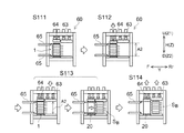
なお、以上の電池パック組付け装置60は、例えば図12に示すように、以下の解体工程S111〜114に従うことで電池パック1を解体する際にも好適に使用することができる。なお予め、電池パック組付け装置60のスライダ機構65は、例えば、筐体の後方Rrの側壁から、前方Fの側壁に移動させておくとよい。
そしてまず、解体工程S111では、電池パック1を電池パック組付け装置60にセットする。具体的には、電池パック1を前方Fの組立エリアに配置する。このとき、単電池10の配列方向Zが電池パック組付け装置60の高さ方向Hと一致するように、電池パック1を配置する。
[Dismantling method 2]
As shown in FIG. 12, for example, the battery
First, in the disassembling step S111, the
次いで、解体工程S112では、電池パック1を配列方向Zに沿って圧縮する方向に、加圧する。具体的には、電池パック組付け装置60の拡大抑制治具64を、電池パック1の拘束フープ部24を配列方向Zで圧縮する方向に変位させる。これにより、エンドプレート部21、22の離間距離は、配列方向Zで縮小し、電池スタックSBの配列方向Zの寸法も縮小される。このとき、エンドプレート部21、22の離間距離、すなわち圧縮後の電池スタックSBの配列方向Zの寸法が、第二寸法A2となるように拡大抑制治具64を変位させるとよい。
Next, in the dismantling step S112, the
解体工程S113では、変位させた第一エンドプレート部21と第二エンドプレート部22との間から、電池スタックSBを取り出す。具体的には、まず、圧縮部63の下面と、圧縮エリアのベース部61の上面(スペーサの上面であり得る。)との間の距離が第二寸法A2となるように、圧縮部63の高さ方向Hの位置を調整する。次いで、スライダ機構65を用いて、エンドプレート部21、22の間に位置する電池スタックSBを後方Rrに押すことで、電池スタックSBを後方Rrに滑らせながら移動させる。これにより、電池スタックSBを、電池パック1の拘束機構20から取り出して、圧縮エリアの圧縮部63とベース部61との間の空間に移動させることができる。圧縮エリアは、ここに開示される電池パックの解体方法においては、圧力開放エリアとして機能する。電池スタックSBの上方Uと下方Dとには滑りプレート28、29が配置されている。これにより、電池スタックSBのスライドは、摩擦力を小さく抑制して実施することができる。また、圧縮部63の下面とベース部61の上面との間の距離は第二寸法A2となるように調整されている。このことにより、スライドされた電池スタックSBが急激な拘束力の解除に伴いバラバラに周辺に飛び散ることを抑制して、電池スタックSBを拘束機構20から取り出すことができる。また、滑りプレート28、29の長手方向Yの端部にテーパが設けてあることで、滑りプレート28、29が圧縮部63やベース部61に干渉するのを抑制して、電池スタックSBをスライドさせることができる。
In dismantling step S113, from between the first
解体工程S114では、拡大抑制治具64による拘束フープ部24の圧縮を解除するとともに、電池スタックSBから拘束圧を開放する。具体的には、拡大抑制治具64をエンドプレート部21、22の離間距離が拡大する方向に変位させる。このことにより、拡大抑制治具64によって拘束フープ部24に配列方向に加えていた圧縮応力を開放することができる。また、圧縮部63を、ベース部61からの距離が拡大する方向に変位させる。このことにより、圧縮部63とベース部61との間に取り出された電池スタックSBに加えられている拘束力を開放することができる。圧縮部63の変位は、電池スタックSBからの拘束力の急激な解除に伴う単電池10の飛散等を抑制するために、ゆっくりと行うことが好ましい。これにより、拘束圧を内在させていた電池スタックSBから拘束圧を開放することができ、安全に電池パック1を解体することができる。
In dismantling step S114, with decompressing restraining
上記電池パック1の製造方法と解体方法とにおいて、第一エンドプレート部21、第二エンドプレート部22および拘束フープ部24は一体的に形成されていた。しかしながら、電池パック1の構成はこれに限定されない。例えば、第一エンドプレート部21および第二エンドプレート部22と、拘束フープ部24とが、別個の構成要素として形成されている場合であっても、上記の製造方法や解体方法を適用することは可能である。また、上記製造方法と解体方法とにおいて、電池パック1の第一エンドプレート部21および第二エンドプレート部22の長手方向の寸法と、拘束フープ部24の左右の側壁部24L、24Rの長手方向の寸法とは同一となるように構成されていた。しかしながら、電池パック1の構成はこれに限定されない。例えば、拘束フープ部24の側壁部24L、24Rの長手方向の寸法が、エンドプレート部21、22の長手方向の寸法よりも小さい場合や、拘束機構20が2つ以上の拘束フープ部24を備えている場合であっても、上記の製造方法や解体方法を適用することは可能である。
In the manufacturing method and the disassembling method of the
[用途]
ここに開示される電池パック1は、環状の拘束フープ部24によって複数の単電池10が拘束圧が加えられた状態で拘束されている。このような拘束フープ部24の形態に基き、電池パック1は従来の例えば約5倍〜約10倍といった、高い拘束圧で拘束することができる。このことは、例えば、界面抵抗が高いために内部応力が増大されてしまう複数の全固体電池を拘束してなる電池パック1に対し、高い拘束圧を付与するために特に好適に採用することができる。これによって、例えば、従来よりも内部抵抗が低減された、全固体電池からなる電池パック1を提供することができる。
[Use]
In the
また、このような電池パック1は、高い拘束圧で単電池10を拘束することができることから、ハイレートで大電流を充放電する用途の電池パック1に特に好適に適用することができる。また、充放電に伴う体積膨張率の高い活物質を使用した単電池10を長期にわたって高い拘束力で拘束することが求められる電池パック1や、振動等が発生する環境で使用する用途の電池パック.方向1等に対しても特に好適に適用することができる。このことから、例えば、ここに開示される電池パック1の好適な用途として、プラグインハイブリッド自動車(PHV)、ハイブリッド自動車(HV)、電気自動車(EV)等の車両に搭載される駆動用電源が挙げられる。
Further, since such a
以上、本発明の具体例を詳細に説明したが、これらは例示に過ぎず、特許請求の範囲を限定するものではない。特許請求の範囲に記載の技術には、以上に例示した具体例を様々に変形、変更したものが含まれる。
例えば、第二実施形態で用いられた、一体成形された拘束機構20や滑りプレート28、29は、個々に、第一実施形態における電池パック1の製造方法1および解体方法1において使用してもよい。同様に、第一実施形態で用いられた、エンドプレート部21、22と拘束フープ部24とが別部材として構成された拘束機構20は、第二実施形態における電池パック1の製造方法2および解体方法2において使用してもよい。
Although specific examples of the present invention have been described in detail above, these are merely examples and do not limit the scope of claims. The techniques described in the claims include various modifications and modifications of the specific examples exemplified above.
For example, the integrally molded
1 電池パック
10 単電池
20 拘束機構
21,22 エンドプレート
24 拘束フープ部
24U 上面部
24D 下面部
24R 右側面部
24L 左側面部
28、29 滑りプレート
1
Claims (4)
第一エンドプレート部と第二エンドプレート部とを前記配列方向に沿って離間して配置し、前記第一エンドプレート部と前記第二エンドプレート部とを前記配列方向に平行な面で囲むように環状の拘束フープ部を配置する工程、ここで該環状の拘束フープ部は、前記配列方向に沿う引張方向に弾性領域で変形可能な材質で構成されている、
前記第一エンドプレート部と前記第二エンドプレート部との離間距離が、前記第一電池スタックの前記配列方向の寸法と同じかそれ以上となるように、前記第一エンドプレート部を前記配列方向の前記第二エンドプレート部とは反対側の第三方向に変位させるとともに、前記拘束フープ部を延伸させる工程、ここで前記第一エンドプレート部の変位量は、前記拘束フープ部が前記弾性領域で伸延される範囲であって該拘束フープ部が該延伸により該弾性領域を超えて降伏変形する変位量とはならないように決定される、
変位させた前記第一エンドプレート部と前記第二エンドプレート部との間に、前記第一電池スタックを配列方向が前記第三方向となるように挿入する工程、および、
前記第一エンドプレート部の変位を解除し、前記第一エンドプレート部、前記第二エンドプレート部および該変位の解除によって前記伸延される前の寸法に戻ろうとして弾性収縮する前記拘束フープ部によって、前記複数の単電池に対して前記配列方向に沿って圧縮する方向に荷重を加えながら、前記複数の単電池を拘束する工程、
を含む、電池パックの製造方法。 The process of arranging multiple cells in the array direction to prepare the first battery stack,
The first end plate portion and the second end plate portion are arranged apart from each other along the arrangement direction, and the first end plate portion and the second end plate portion are surrounded by a plane parallel to the arrangement direction. In the step of arranging the annular restraint hoop portion, the annular restraint hoop portion is made of a material that can be deformed in an elastic region in the tensile direction along the arrangement direction.
The first end plate portion is arranged in the arrangement direction so that the separation distance between the first end plate portion and the second end plate portion is equal to or larger than the dimension in the arrangement direction of the first battery stack. In the step of displacing the restraint hoop portion in the third direction opposite to the second end plate portion and stretching the restraint hoop portion, the displacement amount of the first end plate portion is such that the restraint hoop portion has the elastic region. It is determined so that the restraint hoop portion does not have a displacement amount that yields and deforms beyond the elastic region due to the stretching within the range stretched by.
A step of inserting the first battery stack between the displaced first end plate portion and the second end plate portion so that the arrangement direction is the third direction, and
By releasing the displacement of the first end plate portion, the first end plate portion, the second end plate portion, and the restraint hoop portion elastically contracting in an attempt to return to the dimension before being stretched by releasing the displacement. , A step of restraining the plurality of cells while applying a load to the plurality of cells in a direction of compression along the arrangement direction.
How to make a battery pack, including.
前記第二電池スタックを、前記配列方向の寸法が第一寸法となるように前記配列方向に圧縮する工程、
第一エンドプレート部と、第二エンドプレート部と、環状の拘束フープ部とを備え、前記第一エンドプレート部と前記第二エンドプレート部とが前記配列方向に沿って前記第一寸法で離間して対向配置されているとともに、前記配列方向に平行な面において前記拘束フープ部が前記第一エンドプレート部と前記第二エンドプレート部とをその外周に沿って囲むように配置されている拘束機構を用意する工程、
前記第一エンドプレート部と前記第二エンドプレート部との離間距離が、前記第一寸法よりも広がることを抑制する拡大抑制治具を設置する工程、
前記第一エンドプレート部と前記第二エンドプレート部との間に、圧縮された前記第二電池スタックを挿入する工程、および、
前記拡大抑制治具を前記配列方向の前記離間距離が拡大する方向に変位させ、前記拘束機構によって、前記複数の単電池に対して前記配列方向に沿って圧縮する方向に荷重を加えながら、前記複数の単電池を拘束する工程、
を含む、電池パックの製造方法。 A plurality of cells are arranged in the arrangement direction, a first sliding plate is arranged at the end of the plurality of cells in the first direction in the arrangement direction, and a second sliding plate is arranged at the end of the second direction. And the process of preparing the second battery stack,
A step of compressing the second battery stack in the arrangement direction so that the dimension in the arrangement direction becomes the first dimension.
A first end plate portion, a second end plate portion, and an annular restraint hoop portion are provided, and the first end plate portion and the second end plate portion are separated by the first dimension along the arrangement direction. The restraint hoop portion is arranged so as to surround the first end plate portion and the second end plate portion along the outer periphery thereof on a plane parallel to the arrangement direction. The process of preparing the mechanism,
A step of installing an expansion suppressing jig that suppresses the separation distance between the first end plate portion and the second end plate portion from becoming wider than the first dimension.
The step of inserting the compressed second battery stack between the first end plate portion and the second end plate portion, and
The expansion suppressing jig is displaced in the direction in which the separation distance in the arrangement direction is expanded, and the restraining mechanism applies a load to the plurality of cells in the direction of compression along the arrangement direction. The process of restraining multiple cells,
How to make a battery pack, including.
前記複数の単電池を拘束する拘束機構と、
を備える電池パックの解体方法であって、
前記拘束機構は、
前記第一電池スタックの前記配列方向の第一方向の端部に配置される第一エンドプレート部と、
前記第一電池スタックの前記配列方向の第二方向の端部に配置される第二エンドプレート部と、
環状であって、前記第一エンドプレート部の前記第一方向の表面に配置される第一支持部と、前記第二エンドプレート部の前記第二方向の表面に配置される第二支持部と、前記第一支持部と前記第二支持部との間を前記配列方向に沿って連続的に繋ぐ一対の側壁部とを含む拘束フープ部と、
を備えており、
前記第一エンドプレート部を前記第二エンドプレート部に対して相対的に前記第一方向に変位させて、前記拘束フープ部を前記配列方向に沿って伸延させる工程と、
前記第一エンドプレート部と前記第二エンドプレート部との間から、前記第一電池スタックを取り出す工程と、および、
変位された前記第一エンドプレート部を前記第二エンドプレート部に対して相対的に前記第二方向に変位させて、前記拘束フープ部の伸延を解除する工程と、
を含む、電池パックの解体方法。 The first battery stack, in which multiple cells are arranged in the array direction,
The restraint mechanism that restrains the plurality of cells and
It is a method of disassembling the battery pack equipped with
The restraint mechanism is
The first end plate portion arranged at the end portion of the first battery stack in the first direction in the arrangement direction, and the first end plate portion.
A second end plate portion arranged at the end portion of the first battery stack in the second direction in the arrangement direction, and a second end plate portion.
A first support portion which is annular and is arranged on the surface of the first end plate portion in the first direction, and a second support portion arranged on the surface of the second end plate portion in the second direction. , A restraint hoop portion including a pair of side wall portions that continuously connect the first support portion and the second support portion along the arrangement direction.
Equipped with
A step of displacing the first end plate portion in the first direction relative to the second end plate portion and extending the restraint hoop portion along the arrangement direction.
The step of taking out the first battery stack from between the first end plate portion and the second end plate portion, and
A step of displacing the displaced first end plate portion in the second direction relative to the second end plate portion to release the extension of the restraint hoop portion.
How to disassemble the battery pack, including.
前記第二電池スタックを拘束する拘束機構と、
を備える電池パックの解体方法であって、
前記拘束機構は、
前記第二電池スタックの前記配列方向の第一方向の端部に配置される第一エンドプレート部と、
前記第二電池スタックの前記配列方向の第二方向の端部に配置される第二エンドプレート部と、
環状であって、前記第一エンドプレート部の前記第一方向の表面に配置される第一支持部と、前記第二エンドプレート部の前記第二方向の表面に配置される第二支持部と、前記第一支持部と前記第二支持部との間を前記配列方向に沿って連続的に繋ぐ一対の側壁部とを含む拘束フープ部と、
を備えており、
前記電池パックを、前記第二電池スタックの前記配列方向の寸法が第二寸法となるように、前記配列方向に圧縮する工程、
圧縮された前記電池パックの前記配列方向に直交する方向で、圧縮された前記第二電池スタックに隣接する位置に、前記配列方向の寸法が前記第二寸法である圧力開放エリアを用意する工程、
圧縮された前記第二電池スタックの前記第一滑りプレートおよび前記第二滑りプレートを、前記配列方向に直交する方向で前記圧力開放エリアの側に押圧し、前記第二電池スタックを前記第一エンドプレート部と前記第二エンドプレート部との間から前記圧力開放エリアに移動させる工程、および、
前記圧力開放エリアの前記配列方向の寸法を前記第二寸法よりも拡大させることで、圧縮された前記第二電池スタックの圧縮を解消する工程、
を含む、電池パックの解体方法。 A plurality of cells are arranged in the arrangement direction, a first sliding plate is arranged at the end of the plurality of cells in the first direction in the arrangement direction, and a second sliding plate is arranged at the end of the second direction. With the second battery stack
The restraint mechanism that restrains the second battery stack and
It is a method of disassembling the battery pack equipped with
The restraint mechanism is
The first end plate portion arranged at the end portion of the second battery stack in the first direction in the arrangement direction, and the first end plate portion.
A second end plate portion arranged at the end portion of the second battery stack in the second direction in the arrangement direction, and a second end plate portion.
A first support portion which is annular and is arranged on the surface of the first end plate portion in the first direction, and a second support portion arranged on the surface of the second end plate portion in the second direction. , A restraint hoop portion including a pair of side wall portions that continuously connect the first support portion and the second support portion along the arrangement direction.
Equipped with
A step of compressing the battery pack in the arrangement direction so that the dimension of the second battery stack in the arrangement direction becomes the second dimension.
A step of preparing a pressure release area whose dimension in the array direction is the second dimension at a position adjacent to the compressed second battery stack in a direction orthogonal to the array direction of the compressed battery pack.
The first sliding plate and the second sliding plate of the compressed second battery stack are pressed toward the pressure release area in a direction orthogonal to the arrangement direction, and the second battery stack is pushed to the first end. The step of moving from between the plate portion and the second end plate portion to the pressure release area, and
A step of canceling the compression of the compressed second battery stack by enlarging the dimension of the pressure release area in the arrangement direction from the second dimension.
How to disassemble the battery pack, including.
Priority Applications (6)
| Application Number | Priority Date | Filing Date | Title |
|---|---|---|---|
| JP2018003872A JP6975385B2 (en) | 2018-01-12 | 2018-01-12 | Battery pack and its manufacturing method and dismantling method |
| US16/220,286 US11431050B2 (en) | 2018-01-12 | 2018-12-14 | Cell pack and method for producing and method for disassembling the same |
| CN201910026472.7A CN110034253B (en) | 2018-01-12 | 2019-01-11 | Battery pack, method of manufacturing the same, and method of disassembling the same |
| US17/238,981 US11171381B2 (en) | 2018-01-12 | 2021-04-23 | Cell pack and method for producing and method for disassembling the same |
| US17/239,424 US11217855B2 (en) | 2018-01-12 | 2021-04-23 | Cell pack and method for producing and method for disassembling the same |
| US17/813,742 US20220359938A1 (en) | 2018-01-12 | 2022-07-20 | Cell pack and method for producing and method for disassembling the same |
Applications Claiming Priority (1)
| Application Number | Priority Date | Filing Date | Title |
|---|---|---|---|
| JP2018003872A JP6975385B2 (en) | 2018-01-12 | 2018-01-12 | Battery pack and its manufacturing method and dismantling method |
Publications (2)
| Publication Number | Publication Date |
|---|---|
| JP2019125444A JP2019125444A (en) | 2019-07-25 |
| JP6975385B2 true JP6975385B2 (en) | 2021-12-01 |
Family
ID=67214338
Family Applications (1)
| Application Number | Title | Priority Date | Filing Date |
|---|---|---|---|
| JP2018003872A Active JP6975385B2 (en) | 2018-01-12 | 2018-01-12 | Battery pack and its manufacturing method and dismantling method |
Country Status (3)
| Country | Link |
|---|---|
| US (4) | US11431050B2 (en) |
| JP (1) | JP6975385B2 (en) |
| CN (1) | CN110034253B (en) |
Families Citing this family (11)
| Publication number | Priority date | Publication date | Assignee | Title |
|---|---|---|---|---|
| DE102019125382A1 (en) * | 2019-09-20 | 2021-03-25 | Audi Ag | Battery with a pressure-limiting device, functional device with a battery and method for pressure-limiting |
| JP7131523B2 (en) * | 2019-10-16 | 2022-09-06 | トヨタ自動車株式会社 | module |
| JP7172947B2 (en) | 2019-10-29 | 2022-11-16 | トヨタ自動車株式会社 | Battery pack manufacturing method |
| JP7400577B2 (en) * | 2020-03-23 | 2023-12-19 | トヨタ自動車株式会社 | Manufacturing method of assembled battery and assembled battery |
| JP7317760B2 (en) * | 2020-03-31 | 2023-07-31 | トヨタ自動車株式会社 | BATTERY MANUFACTURING METHOD AND BATTERY |
| WO2021215125A1 (en) * | 2020-04-23 | 2021-10-28 | パナソニックIpマネジメント株式会社 | Battery and battery manufacturing method |
| CN114586228A (en) | 2020-08-05 | 2022-06-03 | 株式会社Lg新能源 | Battery module, battery pack including the same, and method of transporting the same |
| CN112388274A (en) * | 2020-11-20 | 2021-02-23 | 深圳市金凯博自动化测试有限公司 | Distance changing mechanism for disassembling battery core |
| CN113258187B (en) * | 2021-04-01 | 2022-08-30 | 上海澜韬智能科技有限公司 | Battery pack of new energy automobile |
| CN114156581B (en) * | 2021-11-30 | 2022-12-02 | 深圳品驾智能科技有限公司 | Power battery's protecting sheathing |
| CN116408752B (en) * | 2023-06-09 | 2023-08-22 | 北京凌禾科技有限公司 | Battery pack disassembling equipment and disassembling method |
Family Cites Families (22)
| Publication number | Priority date | Publication date | Assignee | Title |
|---|---|---|---|---|
| JP3271494B2 (en) | 1995-10-24 | 2002-04-02 | 松下電器産業株式会社 | Stacked sealed alkaline storage battery |
| JP4136328B2 (en) | 2001-05-14 | 2008-08-20 | トヨタ自動車株式会社 | Battery restraint device |
| US20060093890A1 (en) * | 2004-10-29 | 2006-05-04 | Steinbroner Matthew P | Fuel cell stack compression systems, and fuel cell stacks and fuel cell systems incorporating the same |
| KR101108190B1 (en) | 2009-12-23 | 2012-01-31 | 에스비리모티브 주식회사 | Battery module providing improved fixing structure for end plate and the fixing method thereof |
| JP6158081B2 (en) * | 2010-06-28 | 2017-07-05 | エイ123・システムズ・リミテッド・ライアビリティ・カンパニーA123 Systems, Llc | Battery module with retaining band and method of assembly |
| JP5594203B2 (en) * | 2011-03-24 | 2014-09-24 | 株式会社デンソー | Battery pack |
| JP5628105B2 (en) | 2011-07-08 | 2014-11-19 | 本田技研工業株式会社 | Fuel cell stack |
| JP2013051048A (en) * | 2011-08-30 | 2013-03-14 | Sanyo Electric Co Ltd | Power supply device |
| JP2015187913A (en) | 2012-08-09 | 2015-10-29 | 三洋電機株式会社 | Power supply device, and electrically driven vehicle and power storage device having the same |
| JP6292798B2 (en) * | 2013-08-30 | 2018-03-14 | 出光興産株式会社 | Method for producing negative electrode composite |
| JP6123642B2 (en) * | 2013-11-08 | 2017-05-10 | トヨタ自動車株式会社 | All-solid battery charging system |
| JP6442907B2 (en) * | 2014-08-07 | 2018-12-26 | 株式会社豊田自動織機 | Battery module |
| JP6428176B2 (en) * | 2014-11-10 | 2018-11-28 | 株式会社豊田自動織機 | Battery module |
| US9583747B2 (en) * | 2015-01-08 | 2017-02-28 | Ford Global Technologies, Llc | Retention assembly for traction battery cell array |
| JP2016157586A (en) * | 2015-02-24 | 2016-09-01 | トヨタ自動車株式会社 | Method of manufacturing battery module |
| JP6627265B2 (en) * | 2015-06-08 | 2020-01-08 | 株式会社豊田自動織機 | Battery pack |
| DE102015225351A1 (en) * | 2015-12-16 | 2017-06-22 | Bayerische Motoren Werke Aktiengesellschaft | Method for producing a power supply unit |
| RU2608762C1 (en) * | 2015-12-30 | 2017-01-24 | Владимир Леонидович Туманов | Electrochemical device |
| JP6718771B2 (en) * | 2016-08-18 | 2020-07-08 | 旭化成株式会社 | Shock resistant storage module |
| US10566588B2 (en) * | 2016-09-21 | 2020-02-18 | Ford Global Technologies, Llc | Battery cell support assembly |
| DE102017205410A1 (en) * | 2017-03-30 | 2018-10-04 | Robert Bosch Gmbh | battery system |
| JP6568900B2 (en) * | 2017-07-06 | 2019-08-28 | 本田技研工業株式会社 | Battery module |
-
2018
- 2018-01-12 JP JP2018003872A patent/JP6975385B2/en active Active
- 2018-12-14 US US16/220,286 patent/US11431050B2/en active Active
-
2019
- 2019-01-11 CN CN201910026472.7A patent/CN110034253B/en active Active
-
2021
- 2021-04-23 US US17/238,981 patent/US11171381B2/en active Active
- 2021-04-23 US US17/239,424 patent/US11217855B2/en active Active
-
2022
- 2022-07-20 US US17/813,742 patent/US20220359938A1/en active Pending
Also Published As
| Publication number | Publication date |
|---|---|
| US20190221795A1 (en) | 2019-07-18 |
| US11171381B2 (en) | 2021-11-09 |
| JP2019125444A (en) | 2019-07-25 |
| US11217855B2 (en) | 2022-01-04 |
| US11431050B2 (en) | 2022-08-30 |
| US20210242523A1 (en) | 2021-08-05 |
| CN110034253B (en) | 2022-02-08 |
| CN110034253A (en) | 2019-07-19 |
| US20220359938A1 (en) | 2022-11-10 |
| US20210328295A1 (en) | 2021-10-21 |
Similar Documents
| Publication | Publication Date | Title |
|---|---|---|
| JP6975385B2 (en) | Battery pack and its manufacturing method and dismantling method | |
| JP7037676B2 (en) | Rechargeable batteries and electronic devices | |
| JP2020188030A (en) | Secondary battery and electronic apparatus | |
| JP2008091099A (en) | Laminated lithium ion battery | |
| US8450007B2 (en) | Stacked secondary battery | |
| JP7022307B2 (en) | Battery module | |
| JP6960271B2 (en) | All solid state battery | |
| JP7046158B2 (en) | Battery cell | |
| CN112005420A (en) | Solid-state battery | |
| JP4976174B2 (en) | Sealed secondary battery | |
| JP6986206B2 (en) | Batteries assembled | |
| JP6899746B2 (en) | All-solid-state battery and its manufacturing method | |
| CN110383568B (en) | Secondary battery and method for manufacturing secondary battery | |
| JP7068630B2 (en) | All solid state battery | |
| CN111276641A (en) | All-solid-state battery and method for manufacturing same | |
| CN116134657A (en) | Electrochemical cell clamp and related methods | |
| JP7022308B2 (en) | Battery module | |
| JP2018107008A (en) | Manufacturing method of all-solid battery | |
| JP2000156211A (en) | Battery and battery pack | |
| CN113950766A (en) | Laminated battery | |
| JP2003092134A (en) | Nickel hydrogen secondary battery and electric vehicle | |
| WO2024053652A1 (en) | All-solid-state battery | |
| WO2023105940A1 (en) | Solid-state battery | |
| CN111937212B (en) | Battery cell | |
| US20240030483A1 (en) | Cell assembly and all solid-state battery comprising the same |
Legal Events
| Date | Code | Title | Description |
|---|---|---|---|
| A621 | Written request for application examination |
Free format text: JAPANESE INTERMEDIATE CODE: A621 Effective date: 20200224 |
|
| A977 | Report on retrieval |
Free format text: JAPANESE INTERMEDIATE CODE: A971007 Effective date: 20201111 |
|
| A131 | Notification of reasons for refusal |
Free format text: JAPANESE INTERMEDIATE CODE: A131 Effective date: 20201126 |
|
| A521 | Request for written amendment filed |
Free format text: JAPANESE INTERMEDIATE CODE: A523 Effective date: 20210125 |
|
| A131 | Notification of reasons for refusal |
Free format text: JAPANESE INTERMEDIATE CODE: A131 Effective date: 20210520 |
|
| A521 | Request for written amendment filed |
Free format text: JAPANESE INTERMEDIATE CODE: A523 Effective date: 20210714 |
|
| TRDD | Decision of grant or rejection written | ||
| A01 | Written decision to grant a patent or to grant a registration (utility model) |
Free format text: JAPANESE INTERMEDIATE CODE: A01 Effective date: 20211007 |
|
| A61 | First payment of annual fees (during grant procedure) |
Free format text: JAPANESE INTERMEDIATE CODE: A61 Effective date: 20211020 |
|
| R151 | Written notification of patent or utility model registration |
Ref document number: 6975385 Country of ref document: JP Free format text: JAPANESE INTERMEDIATE CODE: R151 |