JP6974900B2 - X線回折法システムにおける二次元検出器の空間的向きを決定する方法 - Google Patents
X線回折法システムにおける二次元検出器の空間的向きを決定する方法 Download PDFInfo
- Publication number
- JP6974900B2 JP6974900B2 JP2017099298A JP2017099298A JP6974900B2 JP 6974900 B2 JP6974900 B2 JP 6974900B2 JP 2017099298 A JP2017099298 A JP 2017099298A JP 2017099298 A JP2017099298 A JP 2017099298A JP 6974900 B2 JP6974900 B2 JP 6974900B2
- Authority
- JP
- Japan
- Prior art keywords
- detector
- orientation
- axis
- sample
- determining
- Prior art date
- Legal status (The legal status is an assumption and is not a legal conclusion. Google has not performed a legal analysis and makes no representation as to the accuracy of the status listed.)
- Active
Links
- 238000002441 X-ray diffraction Methods 0.000 title claims description 9
- 238000001514 detection method Methods 0.000 claims description 31
- 238000000034 method Methods 0.000 claims description 26
- 239000000463 material Substances 0.000 claims description 8
- 238000005259 measurement Methods 0.000 claims description 5
- 230000004044 response Effects 0.000 claims description 4
- 230000008569 process Effects 0.000 claims description 3
- 239000010431 corundum Substances 0.000 description 9
- 229910052593 corundum Inorganic materials 0.000 description 9
- 239000000843 powder Substances 0.000 description 9
- 238000010586 diagram Methods 0.000 description 7
- 238000012937 correction Methods 0.000 description 4
- 239000013078 crystal Substances 0.000 description 4
- 238000006073 displacement reaction Methods 0.000 description 4
- 238000000926 separation method Methods 0.000 description 4
- AQRYNYUOKMNDDV-UHFFFAOYSA-M silver behenate Chemical compound [Ag+].CCCCCCCCCCCCCCCCCCCCCC([O-])=O AQRYNYUOKMNDDV-UHFFFAOYSA-M 0.000 description 4
- 230000008859 change Effects 0.000 description 3
- 238000004364 calculation method Methods 0.000 description 2
- 230000001808 coupling effect Effects 0.000 description 2
- 238000002447 crystallographic data Methods 0.000 description 2
- 230000000694 effects Effects 0.000 description 2
- 230000003287 optical effect Effects 0.000 description 2
- 230000035945 sensitivity Effects 0.000 description 2
- 239000007787 solid Substances 0.000 description 2
- 229910018072 Al 2 O 3 Inorganic materials 0.000 description 1
- 238000000333 X-ray scattering Methods 0.000 description 1
- 238000004458 analytical method Methods 0.000 description 1
- 230000008901 benefit Effects 0.000 description 1
- 230000005540 biological transmission Effects 0.000 description 1
- 238000004590 computer program Methods 0.000 description 1
- 230000003247 decreasing effect Effects 0.000 description 1
- 230000007547 defect Effects 0.000 description 1
- 238000013461 design Methods 0.000 description 1
- KAMAPADCIHYSMA-UHFFFAOYSA-N docosanoic acid;silver Chemical compound [Ag].CCCCCCCCCCCCCCCCCCCCCC(O)=O KAMAPADCIHYSMA-UHFFFAOYSA-N 0.000 description 1
- 238000002474 experimental method Methods 0.000 description 1
- 230000014509 gene expression Effects 0.000 description 1
- 230000001902 propagating effect Effects 0.000 description 1
- 239000010453 quartz Substances 0.000 description 1
- 230000005855 radiation Effects 0.000 description 1
- 239000012925 reference material Substances 0.000 description 1
- 229910052710 silicon Inorganic materials 0.000 description 1
- 239000010703 silicon Substances 0.000 description 1
- VYPSYNLAJGMNEJ-UHFFFAOYSA-N silicon dioxide Inorganic materials O=[Si]=O VYPSYNLAJGMNEJ-UHFFFAOYSA-N 0.000 description 1
- 238000012360 testing method Methods 0.000 description 1
- 238000013519 translation Methods 0.000 description 1
- 230000014616 translation Effects 0.000 description 1
Images


Classifications
-
- G—PHYSICS
- G01—MEASURING; TESTING
- G01N—INVESTIGATING OR ANALYSING MATERIALS BY DETERMINING THEIR CHEMICAL OR PHYSICAL PROPERTIES
- G01N23/00—Investigating or analysing materials by the use of wave or particle radiation, e.g. X-rays or neutrons, not covered by groups G01N3/00 – G01N17/00, G01N21/00 or G01N22/00
- G01N23/20—Investigating or analysing materials by the use of wave or particle radiation, e.g. X-rays or neutrons, not covered by groups G01N3/00 – G01N17/00, G01N21/00 or G01N22/00 by using diffraction of the radiation by the materials, e.g. for investigating crystal structure; by using scattering of the radiation by the materials, e.g. for investigating non-crystalline materials; by using reflection of the radiation by the materials
- G01N23/207—Diffractometry using detectors, e.g. using a probe in a central position and one or more displaceable detectors in circumferential positions
-
- G—PHYSICS
- G01—MEASURING; TESTING
- G01N—INVESTIGATING OR ANALYSING MATERIALS BY DETERMINING THEIR CHEMICAL OR PHYSICAL PROPERTIES
- G01N33/00—Investigating or analysing materials by specific methods not covered by groups G01N1/00 - G01N31/00
- G01N33/0091—Powders
-
- G—PHYSICS
- G01—MEASURING; TESTING
- G01N—INVESTIGATING OR ANALYSING MATERIALS BY DETERMINING THEIR CHEMICAL OR PHYSICAL PROPERTIES
- G01N2223/00—Investigating materials by wave or particle radiation
- G01N2223/05—Investigating materials by wave or particle radiation by diffraction, scatter or reflection
- G01N2223/056—Investigating materials by wave or particle radiation by diffraction, scatter or reflection diffraction
- G01N2223/0566—Investigating materials by wave or particle radiation by diffraction, scatter or reflection diffraction analysing diffraction pattern
-
- G—PHYSICS
- G01—MEASURING; TESTING
- G01N—INVESTIGATING OR ANALYSING MATERIALS BY DETERMINING THEIR CHEMICAL OR PHYSICAL PROPERTIES
- G01N2223/00—Investigating materials by wave or particle radiation
- G01N2223/30—Accessories, mechanical or electrical features
- G01N2223/303—Accessories, mechanical or electrical features calibrating, standardising
-
- G—PHYSICS
- G01—MEASURING; TESTING
- G01N—INVESTIGATING OR ANALYSING MATERIALS BY DETERMINING THEIR CHEMICAL OR PHYSICAL PROPERTIES
- G01N2223/00—Investigating materials by wave or particle radiation
- G01N2223/30—Accessories, mechanical or electrical features
- G01N2223/32—Accessories, mechanical or electrical features adjustments of elements during operation
-
- G—PHYSICS
- G01—MEASURING; TESTING
- G01N—INVESTIGATING OR ANALYSING MATERIALS BY DETERMINING THEIR CHEMICAL OR PHYSICAL PROPERTIES
- G01N2223/00—Investigating materials by wave or particle radiation
- G01N2223/50—Detectors
- G01N2223/501—Detectors array
Landscapes
- Chemical & Material Sciences (AREA)
- Health & Medical Sciences (AREA)
- Life Sciences & Earth Sciences (AREA)
- Biochemistry (AREA)
- Physics & Mathematics (AREA)
- Analytical Chemistry (AREA)
- General Health & Medical Sciences (AREA)
- General Physics & Mathematics (AREA)
- Immunology (AREA)
- Pathology (AREA)
- Crystallography & Structural Chemistry (AREA)
- Engineering & Computer Science (AREA)
- Food Science & Technology (AREA)
- Medicinal Chemistry (AREA)
- Analysing Materials By The Use Of Radiation (AREA)
Description
πλ=2dsinθ (2)
ただし、λは波長、dは隣接する結晶面の間の距離(d間隔)、θはその角度において回折ピークが観測されるブラッグ角、nは反射の次数として知られる整数である。

Claims (14)
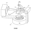
- 試料位置での試料から回折されるX線エネルギーを検出するために用いられるX線回折法システムにおける二次元検出器の空間的向きを決定する方法であって、
前記試料位置に多結晶材料を配置するステップと、
回折されたX線エネルギーがそれから出力されるように、X線ビームを前記多結晶材料に向かって導くステップと、
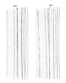
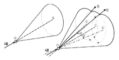
前記X線ビームの方向と検出器の検出面の中心から前記試料までの直線との間で定義される第1のスイング角において位置決めされた前記検出器を用いて、前記回折されたX線エネルギーによって形成される第1の回折パターンを検出するステップと、
前記第1のスイング角とは異なる第2のスイング角に位置決めされた前記検出器を用いて、前記回折されたX線エネルギーによって形成される第2の回折パターンを検出するステップと、
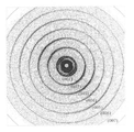
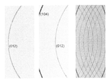
前記検出面上の前記検出された第1及び第2の回折パターンの位置を比較し、それに応答して前記空間的向きを決定するステップであって、前記第1及び第2の回折パターンの間の交差の点を特定し、それらの交点の相対位置を、既知の検出器の向きに対応する予想される相対位置と比較することを含む、該ステップと
を含むことを特徴とする方法。 - 前記第1及び第2のスイング角とは異なるスイング角において位置決めされた前記検出器を用いて、前記回折されたX線エネルギーによって形成される少なくとも1つの追加の回折パターンを検出し、前記検出面上の前記検出された回折パターンの位置を比較し、それに応答して前記空間的向きを決定するステップをさらに含むことを特徴とする請求項1に記載の方法。
- 前記検出器の前記空間的向きを決定するステップは、前記試料の中心と前記検出器の検出面の中心との間の軸の周りの、前記検出器の回転方向の向きを決定するステップを含むことを特徴とする請求項1に記載の方法。
- 前記検出器の前記空間的向きを決定するステップは、前記検出器の検出面の平面内の軸の周りの、前記検出器の回転方向の向きを決定するステップを含むことを特徴とする請求項1に記載の方法。
- 前記軸は第1の軸であり、前記検出器の前記空間的向きを決定するステップは、前記第1の軸に垂直な前記検出器の検出面の平面内の第2の軸の周りの、前記検出器の回転方向の向きを決定するステップをさらに含むことを特徴とする請求項4に記載の方法。
- 前記検出器の前記空間的向きを決定した後に、それに対して較正プロセスの一部として必要な調整を行うステップをさらに含むことを特徴とする請求項1に記載の方法。
- 前記検出器の前記空間的向きを決定した後に、所望の向きからの前記空間的向きの偏差を補正するように、後続の回折法測定を補償するステップをさらに含むことを特徴とする請求項1に記載の方法。
- 試料位置での試料から回折されるX線エネルギーを検出するために用いられるX線回折法システムにおける二次元検出器の空間的向きを較正する方法であって、
試料位置に多結晶材料を配置するステップと、
回折されたX線エネルギーがそれから出力されるように、X線ビームを前記多結晶材料に向かって導くステップと、
前記X線ビームの方向と検出器の検出面の中心から前記試料までの直線との間で定義される複数の異なるスイング角において位置決めされた前記検出器を用いて、前記回折されたX線エネルギーによって形成される複数の回折パターンを検出するステップと、
前記検出面上の前記検出された回折パターンの位置を比較し、それに応答して前記空間的向きを決定するステップであって、前記回折パターンの間の交差の点を特定し、それらの交点の相対位置を、既知の検出器の向きに対応する予想される相対位置と比較することを含む、該ステップと、
前記検出器を較正された位置に向け直すように、前記回折パターンの相対位置に基づいて、前記検出器の前記向きを調整するステップと
を含むことを特徴とする方法。 - 前記検出器の前記空間的向きを較正するステップは、前記試料の中心と前記検出器の検出面の中心との間の軸の周りの、前記検出器の回転方向の向きを調整するステップを含むことを特徴とする請求項8に記載の方法。
- 前記検出器の前記空間的向きを較正するステップは、前記検出器の検出面の平面内の軸の周りの、前記検出器の回転方向の向きを調整するステップを含むことを特徴とする請求項8に記載の方法。
- 前記軸は第1の軸であり、前記検出器の前記空間的向きを調整するステップは、前記第1の軸に垂直な前記検出器の検出面の平面内の第2の軸の周りの、前記検出器の回転方向の向きを調整するステップをさらに含むことを特徴とする請求項10に記載の方法。
- 試料位置での試料から回折されるX線エネルギーを検出するために用いられる、二次元検出器を有するX線回折法システムにおいて、検出器の検出面の中心と、前記試料位置の中心との間のロール軸の周りの前記検出器の角度配向を決定する方法であって、
前記試料位置に多結晶材料を配置するステップと、
前記回折されたX線エネルギーがそれから出力されるように、X線ビームを第1の方向に沿って、前記多結晶材料に向かって導くステップと、
前記ロール軸が、前記第1の方向に実質的に垂直となるように、前記検出器を位置決めするステップと、
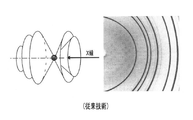
前記検出面の前記中心の極めて近傍にある、前記回折されたX線エネルギーによって形成される回折パターンの実質的に線形な部分を検出し、前記検出器の画素アレイに対する前記線形な部分の向きを識別するステップと、
を含むことを特徴とする方法。 - 前記検出器の前記角度配向を決定した後に、それに対して較正プロセスの一部として必要な調整を行うステップをさらに含むことを特徴とする請求項12に記載の方法。
- 前記検出器の前記角度配向を決定した後に、所望の向きからの前記角度配向の偏差を補正するように、後続の回折法測定を補償するステップをさらに含むことを特徴とする請求項12に記載の方法。
Applications Claiming Priority (2)
| Application Number | Priority Date | Filing Date | Title |
|---|---|---|---|
| US15/162,889 | 2016-05-24 | ||
| US15/162,889 US10444169B2 (en) | 2016-05-24 | 2016-05-24 | Two-dimensional X-ray detector position calibration and correction with diffraction pattern |
Publications (3)
| Publication Number | Publication Date |
|---|---|
| JP2017211380A JP2017211380A (ja) | 2017-11-30 |
| JP2017211380A5 JP2017211380A5 (ja) | 2020-04-30 |
| JP6974900B2 true JP6974900B2 (ja) | 2021-12-01 |
Family
ID=58709830
Family Applications (1)
| Application Number | Title | Priority Date | Filing Date |
|---|---|---|---|
| JP2017099298A Active JP6974900B2 (ja) | 2016-05-24 | 2017-05-18 | X線回折法システムにおける二次元検出器の空間的向きを決定する方法 |
Country Status (3)
| Country | Link |
|---|---|
| US (1) | US10444169B2 (ja) |
| EP (1) | EP3249393B1 (ja) |
| JP (1) | JP6974900B2 (ja) |
Families Citing this family (5)
| Publication number | Priority date | Publication date | Assignee | Title |
|---|---|---|---|---|
| JP7050273B2 (ja) * | 2017-08-22 | 2022-04-08 | 国立大学法人金沢大学 | 回折環計測装置 |
| FR3103897B1 (fr) * | 2019-12-02 | 2022-04-01 | Safran | Dispositif et procédé de mesure des angles d’orientation d’un système d’imagerie x |
| JP7300718B2 (ja) * | 2019-12-13 | 2023-06-30 | 株式会社リガク | 制御装置、システム、方法およびプログラム |
| US11953707B2 (en) * | 2020-01-14 | 2024-04-09 | Purdue Research Foundation | Smooth surface diffraction grating lens and method for manufacturing the same |
| CN115954070B (zh) * | 2022-12-29 | 2024-03-29 | 中国科学院福建物质结构研究所 | 一种高角度x射线孪生衍射点的衍射强度的校正方法 |
Family Cites Families (6)
| Publication number | Priority date | Publication date | Assignee | Title |
|---|---|---|---|---|
| KR20050037086A (ko) * | 2003-10-17 | 2005-04-21 | 삼성전자주식회사 | X선 회절 분석기 및 이 분석기의 측정 위치 보정방법 |
| US7190762B2 (en) * | 2004-10-29 | 2007-03-13 | Broker Axs, Inc | Scanning line detector for two-dimensional x-ray diffractometer |
| JP4581126B2 (ja) * | 2005-03-09 | 2010-11-17 | 独立行政法人物質・材料研究機構 | X線回折分析方法およびx線回折分析装置 |
| DE102009015507B4 (de) * | 2009-04-02 | 2010-12-23 | Bundesrepublik Deutschland, vertr.d.d. Bundesministerium für Wirtschaft und Technologie, d.vertr.d.d. Präsidenten der Physikalisch-Technischen Bundesanstalt | Verfahren zum Messen eines Rollwinkels und Rollwinkelmessvorrichtung |
| US8687766B2 (en) * | 2010-07-13 | 2014-04-01 | Jordan Valley Semiconductors Ltd. | Enhancing accuracy of fast high-resolution X-ray diffractometry |
| KR101256596B1 (ko) * | 2011-01-19 | 2013-04-19 | 한국표준과학연구원 | 실리콘 단결정의 비축을 이용한 x선 회절용 무반사 샘플홀더, 그 샘플홀더의 제조방법, 그 샘플홀더를 포함하는 x선 회절분석시스템 및 회절분석방법 |
-
2016
- 2016-05-24 US US15/162,889 patent/US10444169B2/en active Active
-
2017
- 2017-05-15 EP EP17170979.3A patent/EP3249393B1/en active Active
- 2017-05-18 JP JP2017099298A patent/JP6974900B2/ja active Active
Also Published As
| Publication number | Publication date |
|---|---|
| EP3249393A1 (en) | 2017-11-29 |
| EP3249393B1 (en) | 2021-10-13 |
| US10444169B2 (en) | 2019-10-15 |
| US20170343490A1 (en) | 2017-11-30 |
| JP2017211380A (ja) | 2017-11-30 |
Similar Documents
| Publication | Publication Date | Title |
|---|---|---|
| JP6974900B2 (ja) | X線回折法システムにおける二次元検出器の空間的向きを決定する方法 | |
| KR102013090B1 (ko) | 평면도 측정 방법 및 핀 높이 조정 방법 | |
| JP2017519979A (ja) | 2次元x線検出器を使用する同時格子定数精密化のための統合された逆格子空間マッピング | |
| JP5393126B2 (ja) | 透過電子顕微鏡のゴニオメ−タを利用した隣り合う結晶粒の結晶学的方位関係測定装置及びそれによる結晶粒界の特性の糾明方法 | |
| CN114485389A (zh) | 畸变像差校正处理装置、畸变像差校正方法及存储介质 | |
| US20190017948A1 (en) | Substitution Site Measuring Equipment and Substitution Site Measuring Method | |
| JP6927695B2 (ja) | 走査2次元検出器を用いて正確なx線回折データを収集する方法 | |
| US20130322605A1 (en) | Method for determination of geometrical sensor shifts in flat panel x-ray image detectors | |
| US10620141B2 (en) | Measuring and analyzing residual stresses and their gradients in materials using high resolution grazing incidence X-ray diffraction | |
| KR100936746B1 (ko) | Χ-선 토포그래피에 의한 결함의 3-차원 분포의 분석 | |
| Bauch et al. | Innovative Analysis of X‐ray Microdiffraction Images on Selected Applications of the Kossel Technique | |
| EP3019857B1 (en) | X-ray diffraction-based defective pixel correction method using an active pixel array sensor | |
| CN207622709U (zh) | 基于光谱共焦技术的手机曲面外壳轮廓测量设备 | |
| Horn et al. | Improved calibration of area detectors using multiple placements | |
| JP5470525B2 (ja) | 全反射蛍光x線分析装置 | |
| JP2016205893A (ja) | 結晶方位測定装置の校正方法 | |
| JP3629542B2 (ja) | 蛍光x線分析装置 | |
| WO2012136993A1 (en) | Methods, apparatuses and computer programs for crystallography | |
| US6873403B2 (en) | Halation-prevention filter, image analysis device equipped with said halation-prevention filter, and diffraction pattern intensity analysis method and diffraction pattern intensity correction program that use said halation-prevention filter | |
| KR102205290B1 (ko) | 보조광원을 활용한 영상-기반 구조물 계측 시스템 | |
| CN109212585B (zh) | 一种用于检测中子单色器镶嵌角分布的测试方法及装置 | |
| CN210775283U (zh) | 一种辐射成像指标测试设备及检查装置 | |
| WO2023203744A1 (ja) | 撮像システム及び撮像方法 | |
| JP7180432B2 (ja) | データ処理装置、データ処理方法及びプログラム | |
| JPH06229953A (ja) | 単結晶材料の結晶格子面測定装置 |
Legal Events
| Date | Code | Title | Description |
|---|---|---|---|
| A521 | Request for written amendment filed |
Free format text: JAPANESE INTERMEDIATE CODE: A523 Effective date: 20200323 |
|
| A621 | Written request for application examination |
Free format text: JAPANESE INTERMEDIATE CODE: A621 Effective date: 20200323 |
|
| A977 | Report on retrieval |
Free format text: JAPANESE INTERMEDIATE CODE: A971007 Effective date: 20210303 |
|
| A131 | Notification of reasons for refusal |
Free format text: JAPANESE INTERMEDIATE CODE: A131 Effective date: 20210323 |
|
| A521 | Request for written amendment filed |
Free format text: JAPANESE INTERMEDIATE CODE: A523 Effective date: 20210525 |
|
| TRDD | Decision of grant or rejection written | ||
| A01 | Written decision to grant a patent or to grant a registration (utility model) |
Free format text: JAPANESE INTERMEDIATE CODE: A01 Effective date: 20211005 |
|
| A61 | First payment of annual fees (during grant procedure) |
Free format text: JAPANESE INTERMEDIATE CODE: A61 Effective date: 20211102 |
|
| R150 | Certificate of patent or registration of utility model |
Ref document number: 6974900 Country of ref document: JP Free format text: JAPANESE INTERMEDIATE CODE: R150 |