JP6974792B2 - Signal system, server, signal display method - Google Patents
Signal system, server, signal display method Download PDFInfo
- Publication number
- JP6974792B2 JP6974792B2 JP2017142925A JP2017142925A JP6974792B2 JP 6974792 B2 JP6974792 B2 JP 6974792B2 JP 2017142925 A JP2017142925 A JP 2017142925A JP 2017142925 A JP2017142925 A JP 2017142925A JP 6974792 B2 JP6974792 B2 JP 6974792B2
- Authority
- JP
- Japan
- Prior art keywords
- information
- signal
- vehicle
- point
- predetermined
- Prior art date
- Legal status (The legal status is an assumption and is not a legal conclusion. Google has not performed a legal analysis and makes no representation as to the accuracy of the status listed.)
- Active
Links
Images


Landscapes
- Traffic Control Systems (AREA)
Description
本発明は、信号システム、サーバ、信号表示方法に関する。 The present invention relates to a signal system, a server, and a signal display method.
従来、潜在危険地点(要注意箇所)を抽出し、前記潜在危険地点の情報を車両に送信することで安全運転を支援するシステムが開発されている。 Conventionally, a system has been developed that supports safe driving by extracting potential danger points (points requiring attention) and transmitting information on the potential danger points to a vehicle.
たとえば、特許文献1(国際公開第2014/157359号)には、以下のようなマップ生成システムが掲載されている。すなわち、マップ生成システムは、少なくとも速度、加速度、減速度を含む車速情報を車両から収集し、収集した前記車速情報から、所定条件を満たす急減速事象が生じた第一位置と前記急減速事象が生じた際の前記車両の進行方向とを含む急減速情報を抽出する抽出部と、地図データを記憶する記憶部と、前記記憶部が記憶する前記地図データを、所定サイズおよび所定分割数で複数のメッシュに区切ったメッシュ地図データを生成する分割部と、前記抽出部が抽出した前記急減速情報と、前記分割部が生成した前記メッシュ地図データと、に基づいて、前記自車両が通過するときに注意が必要な位置を要注意箇所として推定する推定部と、を備える。 For example, Patent Document 1 (International Publication No. 2014/157359) describes the following map generation system. That is, the map generation system collects vehicle speed information including at least speed, acceleration, and deceleration from the vehicle, and from the collected vehicle speed information, the first position where a sudden deceleration event satisfying a predetermined condition occurs and the sudden deceleration event are obtained. A plurality of extraction units for extracting sudden deceleration information including the traveling direction of the vehicle when it occurs, a storage unit for storing map data, and the map data stored in the storage unit with a predetermined size and a predetermined number of divisions. When the own vehicle passes based on the division unit that generates the mesh map data divided into the meshes, the sudden deceleration information extracted by the extraction unit, and the mesh map data generated by the division unit. It is provided with an estimation unit that estimates a position requiring attention as a point requiring attention.
特許文献1に記載のマップ生成システムでは、運転支援システムにおける運転支援箇所を抽出する抽出精度を向上させることができる。しかしながら、このシステムでは、車両の車速情報に基づいて要注意箇所を推定することができるが、ドライバを含む車両の搭乗者(以下、「ドライバ等」とも称する。)が要注意箇所であるか否かを判断するにあたり、要注意箇所であることを容易に認識するための手段については開示も示唆もされていない。 In the map generation system described in Patent Document 1, it is possible to improve the extraction accuracy of extracting the driving support points in the driving support system. However, in this system, it is possible to estimate the points requiring attention based on the vehicle speed information of the vehicle, but whether or not the passengers of the vehicle including the driver (hereinafter, also referred to as "drivers") are the points requiring attention. No disclosure or suggestion has been made regarding the means for easily recognizing that it is a point requiring attention.
この発明は、上述の課題を解決するためになされたもので、その目的は、運転支援において、ドライバ等が要注意箇所を容易に認識することが可能な信号システム、サーバ、信号表示方法を提供することである。 The present invention has been made to solve the above-mentioned problems, and an object thereof is to provide a signal system, a server, and a signal display method capable of easily recognizing a point requiring attention by a driver or the like in driving assistance. It is to be.
(1)上記課題を解決するために、この発明のある局面に係わる信号システムは、車両と、所定情報を収集する収集部と、前記所定情報に基づいて所定地点の信号情報を生成する生成部と、を備える信号システムであって、前記車両は、前記信号情報に基づく信号表示情報を、前記車両の内部の所定空間に表示する。 (1) In order to solve the above problems, the signal system according to a certain aspect of the present invention includes a vehicle, a collection unit that collects predetermined information, and a generation unit that generates signal information at a predetermined point based on the predetermined information. The vehicle is a signal system including, and the vehicle displays signal display information based on the signal information in a predetermined space inside the vehicle.
(12)上記課題を解決するために、この発明のある局面に係わる信号表示方法は、所定情報を収集するステップと、前記所定情報に基づいて所定地点の信号情報を生成するステップと、前記信号情報に基づく信号表示情報を、車両の内部の所定空間に表示するステップとを含む。 (12) In order to solve the above problems, the signal display method according to a certain aspect of the present invention includes a step of collecting predetermined information, a step of generating signal information at a predetermined point based on the predetermined information, and the signal. It includes a step of displaying information-based signal display information in a predetermined space inside the vehicle.
本発明は、このような特徴的な処理部や特徴的な処理を備える、信号システム、信号表示方法として実現することができるだけでなく、信号システムに用いられるサーバとして実現したりすることができる。また、かかる処理をコンピュータに実行させるためのプログラムとして実現したりすることができる。また、信号システムの一部又は全部を実現する半導体集積回路として実現することができる。また、車両に代えて、車両に搭載される車載装置を用いて実現することができる。 The present invention can be realized not only as a signal system and a signal display method provided with such a characteristic processing unit and characteristic processing, but also as a server used in a signal system. Further, it can be realized as a program for causing a computer to execute such a process. Further, it can be realized as a semiconductor integrated circuit that realizes a part or all of the signal system. Further, it can be realized by using an in-vehicle device mounted on the vehicle instead of the vehicle.
本発明によれば、ドライバ等が要注意箇所を容易に認識することができる。 According to the present invention, a driver or the like can easily recognize a point requiring attention.
最初に、本発明の実施形態の内容を列記して説明する。 First, the contents of the embodiments of the present invention will be listed and described.
(1)本発明の実施の形態に係る信号システムは、車両と、所定情報を収集する収集部と、前記所定情報に基づいて所定地点の信号情報を生成する生成部と、を備える信号システムであって、前記車両は、前記信号情報に基づく信号表示情報を、前記車両の内部の所定空間に表示する。 (1) The signal system according to the embodiment of the present invention is a signal system including a vehicle, a collecting unit for collecting predetermined information, and a generating unit for generating signal information at a predetermined point based on the predetermined information. Therefore, the vehicle displays signal display information based on the signal information in a predetermined space inside the vehicle.
このような構成により、要注意箇所を可視化することができる。したがって、ドライバ等が要注意箇所を容易に認識することができる。 With such a configuration, it is possible to visualize the points requiring attention. Therefore, the driver or the like can easily recognize the points requiring attention.
(2)好ましくは、前記所定地点は、信号灯器を備える信号機が設置されていない交差点であり、前記所定情報は、前記交差点に流入する道路上に位置する存在車両の位置情報を含む。 (2) Preferably, the predetermined point is an intersection in which a traffic light equipped with a signal lamp is not installed, and the predetermined information includes position information of an existing vehicle located on a road flowing into the intersection.
このような構成により、交差点に信号機を設置しなくても済むので、たとえば、信号機の設置や運用に係るコストを削減することができる。 With such a configuration, it is not necessary to install a traffic light at an intersection, so that it is possible to reduce costs related to the installation and operation of a traffic light, for example.
(3)好ましくは、前記所定地点は、1又は複数の信号灯器を備える信号機が設置された交差点であり、前記信号灯器のうちの少なくとも1つは動作を停止しており、前記所定情報は、前記交差点に流入する道路上に位置する存在車両の位置情報を含む。 (3) Preferably, the predetermined point is an intersection in which a traffic light equipped with one or a plurality of signal lamps is installed, and at least one of the signal lamps has stopped operating, and the predetermined information is based on the predetermined information. Includes location information of existing vehicles located on the road flowing into the intersection.
このような構成により、たとえば交差点に設置された信号灯器の動作が停止する事態になっても、ドライバ等は車両に表示されたこの交差点に係る信号表示情報で車両の走行に必要な信号情報を把握できるので、交通の運用を適切に継続することができる。 With such a configuration, for example, even if the operation of the signal lamp installed at the intersection is stopped, the driver or the like can use the signal display information related to this intersection displayed on the vehicle to display the signal information necessary for the vehicle to travel. Since it can be grasped, it is possible to continue the operation of traffic appropriately.
(4)好ましくは、前記所定情報は、前記交差点に流入する全ての道路上に位置する全ての存在車両の位置情報を含む。 (4) Preferably, the predetermined information includes the position information of all existing vehicles located on all the roads flowing into the intersection.
このような構成により、全ての存在車両の位置情報に基づき交通信号制御を行なうことができるので、交通の運用を適切に行なうことができ、また車両を集中的に管理することができる。 With such a configuration, traffic signal control can be performed based on the position information of all existing vehicles, so that traffic operation can be performed appropriately and vehicles can be centrally managed.
(5)好ましくは、前記所定情報は、前記車両の進行方向の道路上の第1地点に関する異常検知情報を含み、前記所定地点は、前記車両の位置から前記第1地点に至るまでの地点であり、前記生成部は、前記異常検知情報に含まれる異常の程度に応じて前記信号情報を生成する。 (5) Preferably, the predetermined information includes abnormality detection information regarding a first point on the road in the traveling direction of the vehicle, and the predetermined point is a point from the position of the vehicle to the first point. Yes, the generation unit generates the signal information according to the degree of abnormality included in the abnormality detection information.
このような構成により、第1地点の異常を検知している場合に、その第1地点にさしかかる前の所定地点でドライバ等はその異常を把握することができるので、ドライバ等にこの異常に係る注意を促すことができる。 With such a configuration, when an abnormality at the first point is detected, the driver or the like can grasp the abnormality at a predetermined point before approaching the first point, so that the driver or the like is concerned with this abnormality. Can call attention.
(6)好ましくは、前記所定情報は、前記第1地点に設置された感知器での歩行者数の感知結果を含み、前記異常の程度は、前記感知結果と所定閾値との比較に応じて決定される。 (6) Preferably, the predetermined information includes the detection result of the number of pedestrians by the sensor installed at the first point, and the degree of the abnormality depends on the comparison between the detection result and the predetermined threshold value. It is determined.
このような構成により、ドライバ等は、たとえば通学路や住宅街等、人間の急な飛び出しが発生しやすい地点を感知することができ、ドライバ等に人間の急な飛び出しに係る注意を促すことができる。 With such a configuration, the driver or the like can detect a point where a sudden jump of a human is likely to occur, such as a school road or a residential area, and can alert the driver or the like to be careful about the sudden jump of a human. can.
(7)好ましくは、前記所定情報は、前記第1地点に設置された感知器での、落石及び崩落のうちの少なくともいずれか1つに関する感知結果を含み、前記異常の程度は、前記感知結果と所定閾値との比較に応じて決定される。 (7) Preferably, the predetermined information includes the detection result regarding at least one of rockfall and collapse by the sensor installed at the first point, and the degree of the abnormality is the detection result. Is determined according to the comparison with the predetermined threshold value.
このような構成により、ドライバ等は、たとえば山岳等、落石や崩落が発生しやすい地点を感知することができ、ドライバ等に落石や崩落に係る注意を促すことができる。 With such a configuration, the driver or the like can detect a point where rockfall or collapse is likely to occur, such as a mountain, and can call the driver or the like to pay attention to the rockfall or collapse.
(8)好ましくは、前記所定情報は、前記第1地点よりも下流における渋滞末尾位置と前記車両の位置とを含み、前記異常の程度は、前記渋滞末尾位置から前記車両の位置までの距離と、複数の減速度に基づいて設定された複数の判定距離との比較に応じて決定される。 (8) Preferably, the predetermined information includes the position of the tail of the traffic jam downstream from the first point and the position of the vehicle, and the degree of the abnormality is the distance from the tail of the traffic jam to the position of the vehicle. , Determined according to comparison with a plurality of determination distances set based on a plurality of decelerations.
このような構成により、ドライバ等は渋滞末尾位置を感知することができるので、この末尾位置の車両への追突を未然に防ぐことができる。 With such a configuration, the driver or the like can detect the end position of the traffic jam, so that it is possible to prevent a rear-end collision with the vehicle at this end position.
(9)好ましくは、前記車両は、前記信号情報に基づいて前記車両の走行及び停止を制御する制御部を備える。 (9) Preferably, the vehicle includes a control unit that controls the running and stopping of the vehicle based on the signal information.
このように、車両自ら、たとえば所定地点を通過するか、あるいは所定地点の手前で停止するかを制御することで、ドライバ等に掛かる負荷を軽減することができる。 In this way, by controlling whether the vehicle itself passes through, for example, a predetermined point, or stops before the predetermined point, the load on the driver or the like can be reduced.
(10)好ましくは、前記信号表示情報は、信号灯器及びその灯色を認識可能な情報を含む。 (10) Preferably, the signal display information includes a signal lamp and information capable of recognizing the lamp color thereof.
このように、ドライバ等に馴染みのある信号灯器の外観形式で表示することで、ドライバ等にとって分かりやすく、要注意箇所をより容易に認識することができる。 In this way, by displaying the signal lamp in the appearance format familiar to the driver or the like, it is easy for the driver or the like to understand and the points requiring attention can be recognized more easily.
(11)好ましくは、本発明の実施の形態に係る信号システムには、前記収集部と、前記生成部と、前記信号情報を前記車両に送信する送信部とを備える、サーバが用いられる。 (11) Preferably, in the signal system according to the embodiment of the present invention, a server including the collecting unit, the generating unit, and the transmitting unit for transmitting the signal information to the vehicle is used.
このような構成により、たとえば前記信号情報を受信した車両が車両内部の所定空間に表示することで、要注意箇所を可視化することができる。したがって、ドライバ等が要注意箇所を容易に認識することができる。 With such a configuration, for example, the vehicle that has received the signal information displays the signal information in a predetermined space inside the vehicle, so that the points requiring attention can be visualized. Therefore, the driver or the like can easily recognize the points requiring attention.
(12)本発明の実施の形態に係る信号表示方法は、所定情報を収集するステップと、前記所定情報に基づいて所定地点の信号情報を生成するステップと、前記信号情報に基づく信号表示情報を、車両の内部の所定空間に表示するステップとを含む。 (12) The signal display method according to the embodiment of the present invention includes a step of collecting predetermined information, a step of generating signal information at a predetermined point based on the predetermined information, and signal display information based on the signal information. , Including a step to display in a predetermined space inside the vehicle.
このような構成により、要注意箇所を可視化することができる。したがって、ドライバ等が要注意箇所を容易に認識することができる。 With such a configuration, it is possible to visualize the points requiring attention. Therefore, the driver or the like can easily recognize the points requiring attention.
以下、本発明の実施の形態について図面を用いて説明する。なお、図中同一または相当部分には同一符号を付してその説明は繰り返さない。また、以下に記載する実施の形態の少なくとも一部を任意に組み合わせてもよい。 Hereinafter, embodiments of the present invention will be described with reference to the drawings. The same or corresponding parts in the drawings are designated by the same reference numerals and the description thereof will not be repeated. In addition, at least a part of the embodiments described below may be arbitrarily combined.
[構成及び基本動作]
図1は、本発明の実施の形態に係る信号システムの構成を示す図である。
[Configuration and basic operation]
FIG. 1 is a diagram showing a configuration of a signal system according to an embodiment of the present invention.
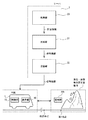
図1を参照して、信号システムは、たとえば、車両1と、サーバ2とを備える。車両1は、たとえば、表示部10と、制御部11とを備える。また、サーバ2は、たとえば、収集部20と、生成部21と、送信部22とを備える。
With reference to FIG. 1, the signaling system comprises, for example, a vehicle 1 and a
サーバ2は、たとえば交通管制センター等に設置され、収集した情報に基づいて信号情報を生成し、その信号情報を所定地点に接近した車両1に対して送信する。信号情報は、たとえば、車両1が所定地点において進行してよいか停止すべきか等を示す情報を含む。より詳細には、信号情報は、信号機の灯色である信号灯色(青・黄・赤等)を示す情報を含み、他にこれらの信号灯色の継続秒数を示す情報や点灯状態(点灯・点滅・滅灯)を示す情報を含んでいてもよい。なお、本発明の実施形態においては、青は「進行することができる」のみならず「安全な状態」や「異常の可能性が低い」等を示し、黄は「安全に止まれないときを除き、止まれ」のみならず「やや危険な状態」や「異常の可能性がやや高い」等を示し、赤は「止まれ」のみならず「危険な状態」や「異常の可能性が高い」等を示す。
The
収集部20は、たとえば、車両(車両の車載装置)からのプローブデータ、交差点に設置された交通信号制御に係る信号機情報、感知器からの人間検知情報、スマートフォンからのGPS情報、感知器からの振動データ等を収集する。これらの情報の詳細については後述するが、これらを総称して以下、「所定情報」とも称する。
The collecting
生成部21は、たとえば、収集部20で収集された所定情報に基づいて、交差点等の所定地点の信号情報を生成する。
The
送信部22は、たとえば、生成部21で生成された信号情報を車両1に送信する。
The
車両1は、サーバ2から送信された信号情報を受信し、その信号情報に基づいて信号表示情報を生成し、ドライバ等に提供する。
The vehicle 1 receives the signal information transmitted from the
表示部10は、たとえば、信号情報に基づく信号表示情報を車両1の内部の所定空間に表示する。
The
信号表示情報は、信号情報に基づいて、表示部10に表示させるために生成した情報である。たとえば、信号灯器及び信号灯色を認識可能な情報である。
また、所定空間は、たとえばディスプレイである。なお、ディスプレイに限らず、たとえば車両1の窓等であってもよい。
The signal display information is information generated for display on the
Further, the predetermined space is, for example, a display. The display is not limited to the display, and may be, for example, a window of the vehicle 1.
図2は、本発明の実施の形態に係る信号システムの表示部への信号表示情報の表示例を示す図である。 FIG. 2 is a diagram showing an example of displaying signal display information on the display unit of the signal system according to the embodiment of the present invention.
図2を参照して、信号表示情報は交差点に表示される仮想の信号灯器であり、この信号灯器は3つの信号灯を含む。各信号灯が示す信号灯色はそれぞれ青・黄・赤であり、いずれか1つの信号灯が青・黄・赤の3色のうちのいずれかを表示する。たとえば、このとき、黄や赤の表示の場合は、黄や赤の表示である理由、すなわち要注意箇所である理由を添えてもよい。このように、ドライバ等に馴染みのある信号灯器の外観形式で表示することで、ドライバ等にとって分かりやすく、要注意箇所をより容易に認識することができる。 With reference to FIG. 2, the signal display information is a virtual signal lamp displayed at an intersection, and this signal lamp includes three signal lights. The signal lamp colors indicated by each signal lamp are blue, yellow, and red, respectively, and any one of the signal lamps displays one of the three colors of blue, yellow, and red. For example, at this time, in the case of yellow or red display, the reason for displaying yellow or red, that is, the reason for requiring attention may be added. In this way, by displaying the signal lamp in the appearance format familiar to the driver or the like, it is easy for the driver or the like to understand and the points requiring attention can be recognized more easily.
また、表示部10には、図2に示すように、信号表示情報と合わせて仮想的な道路を表示させ、所定地点が交差点となるように表示させてもよい。すなわち、車両1が走行している道路が一本道であってもこれと交差する仮想的な道路を表示させてもよい。これにより、ドライバ等はおよそどの位置で停車すればよいかの判断がしやすくなる。
Further, as shown in FIG. 2, the
なお、信号表示情報は3つの信号灯を含む信号灯器を表示する構成に限られず、1個の信号灯のみを表示し、各3色を入れ替えて点灯させる構成であってもよい。また、たとえばディスプレイ等の所定空間上に「進行することができる(青の意味)」・「安全に止まれないときを除き、止まれ(黄の意味)」・「止まれ(赤の意味)」の文字表示の領域及びそれぞれの下に点灯領域を用意すれば、その点灯領域に1色のみの信号灯色(たとえば赤のみ)を点灯することで各状態を表現することもできるし、「進行することができる(青の意味)」・「安全に止まれないときを除き、止まれ(黄の意味)」・「止まれ(赤の意味)」のそれぞれを意味するアイコンを表示させることによって各状態を表現することもできる。 The signal display information is not limited to the configuration of displaying a signal lamp including three signal lamps, and may be configured to display only one signal lamp and light each of the three colors interchangeably. In addition, for example, the characters "can proceed (meaning blue)", "stop (meaning yellow)", and "stop (meaning red)" on a predetermined space such as a display, except when it cannot be stopped safely. If a display area and a lighting area are prepared below each, each state can be expressed by lighting only one signal light color (for example, red only) in the lighting area, and "progress can be progressed." Express each state by displaying icons that mean "can (meaning blue)", "stop (meaning yellow)", "stop (meaning red)", except when you cannot stop safely. You can also.
制御部11は、たとえば、信号情報に基づいて車両1の走行及び停止を制御する。
具体的には、車両1内の制御ユニット(ECU)等により、サーバ2の送信部22から送信された信号情報、あるいは当該信号情報に基づく信号表示情報を自動的に判別し、車速の制御を行なう。たとえば、信号情報において、信号灯色が青の場合には車両1は前進し、信号灯色が黄の場合には車両1は徐行し、信号灯色が赤の場合には車両1は停止する。このように、車両1自ら、たとえば所定地点を通過するか、あるいは所定地点の手前で停止するかを制御することで、ドライバ等に掛かる負荷を軽減することができる。
The control unit 11 controls the running and stopping of the vehicle 1 based on, for example, signal information.
Specifically, the control unit (ECU) in the vehicle 1 automatically determines the signal information transmitted from the
なお、収集部20や生成部21は、サーバ2に備えられていなくてもよく、収集部20及び生成部21のうちの少なくともいずれか1つが車両1に備えられていてもよい。収集部20及び生成部21のいずれも車両1に備わっている場合は、サーバ2を備えなくても、車両1のみで本発明の実施の形態に係る信号システムを実現することができる。
The collecting
また、信号情報に基づく信号表示情報の生成は、車両1を含む各車両で行なわれる構成に限られず、サーバ2の生成部21で行なわれる構成であってもよい。サーバ2の生成部21が当該信号表示情報を生成する構成の場合は、送信部22は当該信号表示情報を車両1を含む各車両に送信する。このような構成により、各車両で信号表示情報を生成する手間を省くことができる。これは後述するそれぞれの実施形態においても同様である。
Further, the generation of the signal display information based on the signal information is not limited to the configuration performed by each vehicle including the vehicle 1, and may be the configuration performed by the
以下、本発明の実施の形態をさらに具体化した第1実施形態〜第4実施形態について順に説明する。第1実施形態〜第4実施形態それぞれで、上述の所定情報や所定地点が異なっている。 Hereinafter, the first to fourth embodiments, which further embody the embodiments of the present invention, will be described in order. The above-mentioned predetermined information and the predetermined point are different in each of the first embodiment to the fourth embodiment.
<第1実施形態>
図3は、本発明の第1実施形態に係る信号システムの構成を示す図である。
図3を参照して、所定地点は、信号灯器を備える信号機が設置されていない交差点を示す交差点I1である。あるいは、所定地点は、1又は複数の信号灯器を備える信号機が設置された交差点であって、これらの信号灯器のうちの少なくとも1つは動作を停止している交差点を示す交差点I2である。
<First Embodiment>
FIG. 3 is a diagram showing a configuration of a signal system according to the first embodiment of the present invention.
With reference to FIG. 3, the predetermined point is an intersection I1 indicating an intersection in which a traffic light equipped with a signal lamp is not installed. Alternatively, the predetermined point is an intersection in which a traffic light equipped with one or a plurality of signal lamps is installed, and at least one of these signal lamps is an intersection I2 indicating an intersection in which the operation is stopped.
収集部20は、交差点I1周辺の各車両1a,1b,1c,1dや交差点I2周辺の各車両1e,1f,1g,1hに搭載された車載装置(図3において不図示。)から、たとえばプローブデータを含む所定情報を収集する。具体的には、交差点I1については、流入する道路R10,R11,R12,R13上に位置する車両1(交差点に流入する道路上に位置する車両を以下、「存在車両」とも称する。)である車両1a,1b,1c,1dのプローブデータを収集し、交差点I2については、流入する道路R20,R21,R22,R23上に位置する車両1(存在車両)である車両1e,1f,1g,1hのプローブデータを収集する。
The collecting
プローブデータは、たとえば、所定周期(たとえば、1秒)ごとの、時刻、位置(緯度、経度、高度)、速度、加速度等の情報を含む。 The probe data includes, for example, information such as time, position (latitude, longitude, altitude), velocity, acceleration, etc. for each predetermined cycle (for example, 1 second).
収集部20は、交差点I1や交差点I2周辺の車両だけでなく、他の車両の車載装置からもプローブデータを含む所定情報を収集している場合には、プローブデータに含まれる位置情報と、交差点I1に流入する道路R10,R11,R12,R13や交差点I2に流入する道路R20,R21,R22,R23の地図データとを照合することにより、これらの交差点に係る存在車両のプローブデータを選別することができる。
When the collecting
また、収集部20は、交差点I2に設置されている信号機SN2から交通信号制御に係る信号機情報を収集する。この信号機情報には、たとえば、道路R20,R21,R22,R23に設定されている車両感知器における車両感知情報を含む。
Further, the collecting
生成部21は、たとえば、収集部20が収集したプローブデータに含まれる車両1の位置情報、特に、交差点に流入する道路上に位置する車両1(存在車両)の位置情報に基づいて、この交差点の信号情報を生成する。
The
信号情報の生成は、たとえばパターン制御方式、MODERATO(Management by Origin-DEstination Related Adaptation for Traffic Optimization)制御方式等に従って、特開2009−252066号公報や特開2009−015817号公報等に記載の公知技術により行なわれる。 The signal information is generated according to, for example, a pattern control method, a MODERATO (Management by Origin-DEstination Related Adaptation for Traffic Optimization) control method, etc. It is done by.
ここで、パターン制御方式とは、事前の交通調査に基づいた複数の制御パターンを予め設定し、交差点入口の車両感知器で計測した交通状況に応じて設定された最適なパターンによって制御する方式である。 Here, the pattern control method is a method in which a plurality of control patterns based on a traffic survey in advance are set in advance and controlled by the optimum pattern set according to the traffic condition measured by the vehicle detector at the entrance of the intersection. be.
また、MODERATO制御方式とは、交通状況に応じて信号制御パラメータを自動的に更新するプログラム形成制御方式であり、これを応用すると、交差点の交通量データを交差点入口の車両感知器で計測して、渋滞通過や信号待ちの時間(遅れ時間)を推定し、その時間が最小になるよう計算することができる。 The MODERATO control method is a program formation control method that automatically updates signal control parameters according to traffic conditions. When this is applied, traffic volume data at intersections is measured by a vehicle detector at the entrance of the intersection. , It is possible to estimate the time (delay time) for passing a traffic jam or waiting for a signal, and calculate so that the time is minimized.
また、収集部20は、交差点に流入する全ての道路上に位置する全ての存在車両のプローブデータを収集することが好ましい。このような構成により、全ての存在車両の位置情報に基づき交通信号制御を行なうことができるので、交通の運用を適切に行なうことができ、また車両を集中的に管理することができる。
Further, it is preferable that the collecting
以下、本発明の第1実施形態に係る信号システムのサーバ2における動作を説明する。
Hereinafter, the operation of the signal system according to the first embodiment of the present invention in the
この動作は、たとえば、(1)信号機情報の設定、(2)信号機周辺情報の収集、(3)信号機制御モデルの構築、(4)信号機制御モデルの運用、の4つに分類される。 This operation is classified into four, for example, (1) setting of traffic light information, (2) collection of traffic light peripheral information, (3) construction of traffic light control model, and (4) operation of traffic light control model.
まず「(1)信号機情報の設定」では、たとえば、サーバ2は信号機を設定する場所(交差点)を決定する。この信号機には、仮想的信号機(信号表示情報として車両1の内部の所定空間に表示される信号機をいう。)のみならず、既存の物理的信号機(道路に実際に設置されている信号機をいう。)を含めてもよい。信号機が仮想的信号機の場合に設定する場所は交差点I1であり、信号機が物理的信号機の場合に設定する場所は交差点I2である。
First, in "(1) Setting of traffic light information", for example, the
交差点I1のように仮想的信号機を設定した場合には、この仮想的信号機に係る信号情報を車両1に送信すればよい。そして、車両1のドライバ等がこの信号情報に基づく信号表示情報に従って走行したり、車両1自らがこの信号情報に従って走行すればよい。これにより、交差点に信号機を実際に設置しなくても済むので、たとえば、信号機の設置や運用に係るコストを削減することができる。 When a virtual traffic light is set as in the intersection I1, the signal information related to the virtual traffic light may be transmitted to the vehicle 1. Then, the driver or the like of the vehicle 1 may travel according to the signal display information based on this signal information, or the vehicle 1 itself may travel according to this signal information. As a result, it is not necessary to actually install a traffic light at an intersection, so that it is possible to reduce costs related to the installation and operation of a traffic light, for example.
また、交差点I2のように物理的信号機を設定して、サーバ2がこの物理的信号機を監視し、信号灯器の動作が停止する等、当該信号機が故障したことを検知すると、この物理的信号機を仮想的信号機に置き換え、収集したプローブデータ等に基づきこの仮想的信号機の信号情報を生成し、その信号情報を車両1に送信すればよい。そして、車両1のドライバ等がこの信号情報に基づく信号表示情報に従って走行したり、車両1自らがこの信号情報に従って走行すればよい。これにより、信号灯器の動作が停止する事態になっても、ドライバ等は車両1に表示されたこの交差点に係る信号表示情報で車両1の走行に必要な信号情報を把握できるので、サーバ2は交通の運用を適切に継続することができる。
Further, when a physical traffic light is set like the intersection I2, the
次に「(2)信号機周辺情報の収集」では、たとえば、サーバ2(収集部20)は後述の「(3)信号機制御モデルの構築」のために(1)で設定した信号機の周辺の情報を収集する。具体的には、(1)で決定した交差点が上述の交差点I1である場合には、この交差点I1に流入する道路R10,R11,R12,R13の存在車両のプローブデータを収集する。一方、(1)で決定した交差点が交差点I2である場合には、この交差点I2に流入する道路R20,R21,R22,R23の存在車両のプローブデータを収集するだけでなく、この交差点I2の既存の物理的信号機から信号機情報を収集してもよい。なお、交差点I1や交差点I2の隣接交差点に信号機(物理的信号機)が設置されている場合には、この信号機の信号機情報をさらに収集してもよい。 Next, in "(2) Collection of traffic light peripheral information", for example, the server 2 (collecting unit 20) has information around the traffic light set in (1) for "(3) Construction of a traffic light control model" described later. To collect. Specifically, when the intersection determined in (1) is the above-mentioned intersection I1, probe data of existing vehicles on the roads R10, R11, R12, and R13 flowing into the intersection I1 are collected. On the other hand, when the intersection determined in (1) is the intersection I2, not only the probe data of the existing vehicles of the roads R20, R21, R22, and R23 flowing into the intersection I2 are collected, but also the existing intersection I2 is collected. Traffic light information may be collected from the physical traffic light of. If a traffic light (physical traffic light) is installed at an intersection adjacent to the intersection I1 or I2, the traffic light information of this traffic light may be further collected.
「(3)信号機制御モデルの構築」では、たとえば、サーバ2(生成部21)は(2)で収集した情報を用いて、(1)で設定した信号機に対し所定の信号制御方式を適用する。より詳細には、所定の信号制御方式として、たとえば、上述したパターン制御方式やMODERATO制御方式を適用し、(2)で収集した存在車両のプローブデータや信号機情報に基づき、当該交差点の信号情報を生成するための信号機制御モデルを構築する。この際、さらに、(1)で決定した交差点に流入する道路の各種情報(道路の長さ、車線数等)を用いてもよい。このモデルの構築は、上述したように、特開2009−252066号公報や特開2009−015817号公報等に記載の公知技術を用いればよい。なお、交差点I2の場合には、プローブデータに加えて信号機情報を用いてモデルを構築すれば、信号機が故障する前と後で連続性を保った信号情報を生成できる。 In "(3) Construction of traffic light control model", for example, the server 2 (generation unit 21) applies a predetermined signal control method to the traffic light set in (1) by using the information collected in (2). .. More specifically, for example, the above-mentioned pattern control method or MODERATO control method is applied as a predetermined signal control method, and the signal information of the intersection is obtained based on the probe data and traffic light information of the existing vehicle collected in (2). Build a traffic light control model to generate. At this time, various information (road length, number of lanes, etc.) of the road flowing into the intersection determined in (1) may be further used. As described above, this model may be constructed by using the known techniques described in JP-A-2009-252066, JP-A-2009-015817 and the like. In the case of the intersection I2, if a model is constructed using the traffic light information in addition to the probe data, it is possible to generate signal information that maintains continuity before and after the traffic light fails.
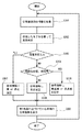
「(4)信号機制御モデルの運用」は、図を用いて詳細に説明する。
図4は、本発明の第1実施形態に係る信号システムのサーバにおける信号機制御モデルの運用に係る動作を示すフロー図である。
"(4) Operation of the traffic light control model" will be described in detail with reference to figures.
FIG. 4 is a flow chart showing an operation related to the operation of the traffic light control model in the server of the signal system according to the first embodiment of the present invention.
まず、サーバ2(収集部20)は、たとえば(1)で設定した信号機に係る信号情報を生成するため、当該信号機の周辺の情報を収集する(ステップS101)。具体的には、(1)で決定した交差点が交差点I1である場合は、この交差点I1に流入する道路R10,R11,R12,R13の存在車両のプローブデータを収集する。(1)で決定した交差点が交差点I2である場合は、この交差点I2に流入する道路R20,R21,R22,R23の存在車両のプローブデータを収集するだけでなく、この交差点I2の既存の物理的信号機から信号機情報を収集してもよい。交差点I2の隣接交差点に信号機(物理的信号機)が設置されている場合には、この信号機の信号機情報をさらに収集してもよい。 First, the server 2 (collecting unit 20) collects information around the traffic light in order to generate signal information related to the traffic light set in (1), for example (step S101). Specifically, when the intersection determined in (1) is the intersection I1, the probe data of the existing vehicles of the roads R10, R11, R12, and R13 flowing into the intersection I1 are collected. When the intersection determined in (1) is the intersection I2, not only the probe data of the existing vehicles of the roads R20, R21, R22, and R23 flowing into the intersection I2 are collected, but also the existing physical of the intersection I2 is collected. Traffic light information may be collected from the traffic light. When a traffic light (physical traffic light) is installed at an adjacent intersection of the intersection I2, the traffic light information of this traffic light may be further collected.
次に、サーバ2(生成部21)は(3)で設定された信号制御方式に従って信号制御を行なう(ステップS102)。より詳細には、サーバ2(生成部21)はステップS101で収集した信号機周辺情報、(3)で構築した信号機制御モデルに基づいて、(1)で設定した信号機に係る信号情報を生成する。なお、交差点I2の場合には、この交差点I2における信号機に異常が発生していないときには信号情報を生成せず、異常が発生しているとき、すなわち信号灯器の動作の停止等を検知したときにのみ、信号情報を生成すればよい。異常が発生していないときには、車両1は実際の信号機の信号灯器に点灯されている信号灯色に従って走行するためである。 Next, the server 2 (generation unit 21) performs signal control according to the signal control method set in (3) (step S102). More specifically, the server 2 (generation unit 21) generates signal information related to the traffic light set in (1) based on the traffic light peripheral information collected in step S101 and the traffic light control model constructed in (3). In the case of the intersection I2, signal information is not generated when no abnormality has occurred in the traffic light at the intersection I2, and when an abnormality has occurred, that is, when the stop of the operation of the signal lamp is detected. Only signal information needs to be generated. This is because when no abnormality has occurred, the vehicle 1 travels according to the color of the signal light lit on the signal light of the actual traffic light.
さらに、サーバ2(送信部22)は、ステップS102で生成した信号情報を(1)で決定した交差点に近づいている車両に送信する(ステップS103)。より詳細には、ステップS101で収集したプローブデータに含まれる位置情報に基づいて、当該交差点に接近している車両か当該交差点から遠ざかっている車両かを判別し、接近していると判断した車両に対して信号情報を送信する。 Further, the server 2 (transmission unit 22) transmits the signal information generated in step S102 to the vehicle approaching the intersection determined in (1) (step S103). More specifically, based on the position information included in the probe data collected in step S101, it is determined whether the vehicle is approaching the intersection or away from the intersection, and the vehicle determined to be approaching is determined. Signal information is transmitted to.
信号情報を受信した車両1(の表示部10)は、当該信号情報に基づく信号表示情報を、車両1の内部の所定空間に表示する。このような構成により、要注意箇所を可視化することができる。したがって、ドライバ等が要注意箇所を容易に認識することができる。 The vehicle 1 (display unit 10) that has received the signal information displays the signal display information based on the signal information in a predetermined space inside the vehicle 1. With such a configuration, it is possible to visualize the points requiring attention. Therefore, the driver or the like can easily recognize the points requiring attention.
なお、信号情報を受信した車両1は、たとえば、周辺車両へこの信号情報をブロードキャスト送信してもよい。こうすることで、交差点周辺の車両は互いに信号情報を共有することができるので、仮にサーバ2から直接信号情報を受信できない車両があっても、他の車両から間接的に信号情報を取得することができ、信号情報の取得を確実にすることができる。
The vehicle 1 that has received the signal information may broadcast the signal information to, for example, peripheral vehicles. By doing so, the vehicles around the intersection can share the signal information with each other, so even if there is a vehicle that cannot directly receive the signal information from the
また、交差点I2において、たとえば車両1の進行方向の物理的信号機に係る信号灯色が青を示していた場合であっても、サーバ2は、この進行方向の道路と交差する他の道路から信号無視等により通過しようとする危険車両を検知した場合には、上記進行方向の仮想的信号機に係る信号灯色を赤にしてもよい。このように、物理的信号機の信号灯色にかかわらず仮想的信号機の信号灯色にてドライバ等に車両の停止を促す構成とすることで、車両同士の衝突事故を防止することができる。なお、この危険車両の検知は、たとえば交差点I2までの距離や、速度、加速度等に基づいて判定することができる。より詳細には、たとえば交差点I2までの距離が所定の閾値を超え、かつこの危険車両の速度や加速度等が所定の閾値を超えたか否か、によって判定することができる。
Further, even if the signal light color of the physical traffic light in the traveling direction of the vehicle 1 is blue at the intersection I2, the
<第2実施形態>
図5は、本発明の第2実施形態に係る信号システムの構成を示す図である。
<Second Embodiment>
FIG. 5 is a diagram showing a configuration of a signal system according to a second embodiment of the present invention.
図5を参照して、所定地点は、たとえば、車両1の位置から車両1の進行方向の道路上の第1地点に至るまでの地点である。具体的には、所定地点は第1地点での異常をドライバ等が予め認識するため第1地点から所定距離(たとえば、300m)を隔てた地点である。第1地点は、たとえば、人間の飛び出しが想定される住宅街の要注意箇所である。 With reference to FIG. 5, the predetermined point is, for example, a point from the position of the vehicle 1 to the first point on the road in the traveling direction of the vehicle 1. Specifically, the predetermined point is a point separated from the first point by a predetermined distance (for example, 300 m) so that the driver or the like recognizes the abnormality at the first point in advance. The first point is, for example, a point of caution in a residential area where humans are expected to jump out.
収集部20は、車両1のプローブデータや、当該第1地点に関する異常検知情報を含む所定情報を収集する。異常検知情報は、所定の異常の可能性を検知した結果を示す情報であり、より詳細には、たとえば、人間の飛び出しが想定される時間帯、すなわち人間が集まりやすい時間帯等において、上記第1地点で人間の存在を検知した人間検知情報である。人間検知情報は、たとえば、上記第1地点に設置された感知器(人間検知センサ)30aを用いて検知した歩行者数等の情報であり、感知器30aからサーバ2の収集部20に送信される。なお、スマートフォンのGPS機能等を用いて人間を検知することもでき、この場合、スマートフォンはGPS機能等による位置情報を人間検知情報としてサーバ2の収集部20に送信する。
The collecting
生成部21は、たとえば、収集部20が収集した人間検知情報やプローブデータ等に基づいて異常検知情報を生成し、その異常検知情報に含まれる異常の程度に基づいて信号情報を生成する。異常の程度は、たとえば、人間検知情報が示す歩行者数と、設定された所定閾値との比較に応じて決定される。
For example, the
以下、本発明の第2実施形態に係る信号システムのサーバにおける動作を説明する。 Hereinafter, the operation of the signal system according to the second embodiment of the present invention in the server will be described.
この動作は、たとえば、(1)信号機情報の設定、(2)信号機周辺情報の収集、(3)信号機制御モデルの構築、(4)信号機制御モデルの運用、の4つに分類される。 This operation is classified into four, for example, (1) setting of traffic light information, (2) collection of traffic light peripheral information, (3) construction of traffic light control model, and (4) operation of traffic light control model.
まず「(1)信号機情報の設定」では、たとえば、サーバ2は信号機を設定する場所を決定する。この場所は、上述の所定地点、たとえば、人間の飛び出しが想定される住宅街の要注意箇所を示す第1地点から所定距離を隔てた地点である。
First, in "(1) Setting of traffic light information", for example, the
次に「(2)信号機周辺情報の収集」では、たとえば、サーバ2(収集部20)は(1)で設定した信号機の周辺の情報を収集する。収集する情報は、たとえば、(1)で設定した信号機の周辺の車両のプローブデータや、第1地点に設置された感知器30aの人間検知情報等を含む。このプローブデータは、上述の第1実施形態で説明した内容と同じであるが、さらに車両が所定地点に向かってくるか、あるいは所定地点から遠ざかっているかを示す情報等を含んでいてもよい。なお、上述のプローブデータや感知器30aに限らず、たとえば人間に対するアンケートによって歩行者数を調査してもよい。
Next, in "(2) Collection of traffic light peripheral information", for example, the server 2 (collecting unit 20) collects information around the traffic light set in (1). The information to be collected includes, for example, probe data of vehicles around the traffic light set in (1), human detection information of the
「(3)信号機制御モデルの構築」は、図を用いて詳細に説明する。
図6は、本発明の第2実施形態に係る信号システムのサーバにおける信号機制御モデルの構築に係る動作を示すフロー図である。
"(3) Construction of a traffic light control model" will be described in detail with reference to figures.
FIG. 6 is a flow chart showing an operation related to the construction of a traffic light control model in the server of the signal system according to the second embodiment of the present invention.
まず、サーバ2(生成部21)は(2)で収集した人間検知情報のうち、特定期間におけるデータを使ってデータ解析を実施する(ステップS201)。ここで、特定期間とは、上述のような事前調査を行なう期間のことである。たとえば、「A:過去1ヶ月間」、「B:過去1年間」、「C:毎年のゴールデンウィーク(GW)期間」、等である。より詳細には、サーバ2は、特定期間における人間検知情報に基づき、たとえば日種毎の歩行者数の平均値や、1時間毎の歩行者数の平均値を計算する。日種は、たとえば「月曜日〜金曜日」と「土曜日・日曜日・祝日」に分類したり、「月曜日〜土曜日」と「日曜日・祝日」に分類したりすることが可能である。
First, the server 2 (generation unit 21) performs data analysis using the data in the specific period among the human detection information collected in (2) (step S201). Here, the specific period is a period during which the above-mentioned preliminary survey is conducted. For example, "A: past one month", "B: past one year", "C: annual Golden Week (GW) period", and the like. More specifically, the
次に、サーバ2(生成部21)は異常検知モデルを構築(モデル化)する(ステップS202)。具体的には、サーバ2は、たとえば、日種と時間帯(たとえば、6−12時、12−18時、18−24時の3つの時間帯)の組合せごとに、ステップS201で計算された日種毎の歩行者数の平均値、及び1時間毎の歩行者数の平均値のうちでその組合せに該当するものの重み付け平均値を求め、それを危険の度合いを示すパラメータ(以下、「危険度」とも称する。)とする。
Next, the server 2 (generation unit 21) builds (models) an abnormality detection model (step S202). Specifically, the
最後に、サーバ2(生成部21)は信号制御に係る信号情報の閾値を設定する(ステップS203)。
より詳細には、ステップS202で算出した日種と時間帯の組合せごとの重み付け平均値が「危険の可能性がない」、「危険の可能性がある」、「危険の可能性が高い」の3つに分類され、後述する「(4)信号機制御モデルの運用」で異常判定の対象となる時点が「危険の可能性がある」日種と時間帯の組合せに該当すれば信号灯色が黄点滅となるように設定し、「危険の可能性が高い」日種と時間帯の組合せに該当すれば信号灯色が赤点滅となるように設定する。
Finally, the server 2 (generation unit 21) sets a threshold value for signal information related to signal control (step S203).
More specifically, the weighted average value for each combination of day type and time zone calculated in step S202 is "no possibility of danger", "possible danger", and "high possibility of danger". It is classified into three categories, and if the time point for abnormality judgment in "(4) Operation of traffic light control model" described later corresponds to the combination of "possible danger" day type and time zone, the signal light color is yellow. Set it to blink, and set the signal light color to blink red if it corresponds to the combination of the "highly dangerous" day type and time zone.
また、ステップS201で計算した日種毎の歩行者数の平均値、及び1時間毎の歩行者数の平均値に基づいて、歩行者数を「異常(危険)の可能性がない」と「異常(危険)の可能性がある」とに分類するための第1閾値W1、「異常(危険)の可能性がある」と分類された歩行者数のうち、さらに「異常(危険)の可能性が高い」を分類するための第2閾値W2(第2閾値W2は第1閾値W1よりも大きい)を決定し、後述する「(4)信号機制御モデルの運用」で異常判定の対象となる歩行者数が第2閾値W2を超えている場合は信号灯色を赤色で点灯させ、第1閾値W1を超えて第2閾値W2以下である場合は信号灯色を黄色で点灯させるように設定する。 Further, based on the average value of the number of pedestrians for each day type calculated in step S201 and the average value of the number of pedestrians for each hour, the number of pedestrians is "there is no possibility of abnormality (danger)". The first threshold W1 for classifying as "possible abnormal (danger)", and the number of pedestrians classified as "possible abnormal (danger)", further "possible abnormal (danger)" The second threshold W2 (the second threshold W2 is larger than the first threshold W1) for classifying "highly probable" is determined, and is subject to abnormality determination in "(4) Operation of traffic light control model" described later. When the number of pedestrians exceeds the second threshold W2, the signal light color is set to light in red, and when the number of pedestrians exceeds the first threshold W1 and is equal to or less than the second threshold W2, the signal light color is set to light in yellow.
「(4)信号機制御モデルの運用」は、図を用いて詳細に説明する。
図7は、本発明の第2実施形態に係る信号システムのサーバにおける信号機制御モデルの運用に係る動作を示すフロー図である。
"(4) Operation of the traffic light control model" will be described in detail with reference to figures.
FIG. 7 is a flow chart showing an operation related to the operation of the traffic light control model in the server of the signal system according to the second embodiment of the present invention.
まず、サーバ2(収集部20)は、上述の所定地点において、たとえば現時点において異常が発生しているかどうか等の評価を行なうために、(1)で設定した信号機の周辺の情報を収集する(ステップS301)。具体的には、(2)と同様に、この信号機の周辺の車両1のプローブデータや、第1地点に設置された感知器30aの人間検知情報等を収集する。
First, the server 2 (collecting unit 20) collects information around the traffic light set in (1) at the above-mentioned predetermined point, for example, in order to evaluate whether or not an abnormality has occurred at the present time (1). Step S301). Specifically, as in (2), probe data of the vehicle 1 around this traffic light, human detection information of the
次に、サーバ2(生成部21)は(3)で作成されたモデルに従って、ステップS301で収集した人間検知情報が示す現時点の歩行者数と、上述の歩行者数の閾値、すなわち(3)で設定された第1閾値W1及び第2閾値W2とを比較することで、異常の判定を行なう(ステップS302)。ステップS302の比較の結果、歩行者数が第1閾値W1と第2閾値W2のうちの少なくともいずれか一方を超えると判定した場合はステップS307に進み、第1閾値W1、第2閾値W2のいずれも超えていないと判定した場合はステップS304へ進む(ステップS303)。 Next, according to the model created in (3), the server 2 (generation unit 21) has the current number of pedestrians indicated by the human detection information collected in step S301 and the above-mentioned threshold value for the number of pedestrians, that is, (3). An abnormality is determined by comparing the first threshold value W1 and the second threshold value W2 set in (step S302). If it is determined as a result of comparison in step S302 that the number of pedestrians exceeds at least one of the first threshold value W1 and the second threshold value W2, the process proceeds to step S307, and either the first threshold value W1 or the second threshold value W2 If it is determined that the above is not exceeded, the process proceeds to step S304 (step S303).
サーバ2(生成部21)は、ステップS303において歩行者数が第2閾値W2を超えると判定した場合は、信号情報に赤色を設定し、第1閾値W1を超えて第2閾値W2以下であると判定した場合は、信号情報に黄色を設定する(ステップS307)。
When the server 2 (generation unit 21) determines in step S303 that the number of pedestrians exceeds the second threshold value W2, the
さらに、サーバ2(生成部21)は、(3)で作成されたモデルに従って、たとえば現時点が危険な日種や時間帯かを判定する(ステップS304)。具体的には、サーバ2は、現時点が(3)で分類された「危険の可能性がある」日種と時間帯の組合せ、「危険の可能性が高い」日種と時間帯の組合せに該当するか否かを判定する。
Further, the server 2 (generation unit 21) determines, for example, whether the current time is a dangerous day type or time zone according to the model created in (3) (step S304). Specifically, the
サーバ2(生成部21)は、ステップS304において、現時点が「危険の可能性がある」日種と時間帯の組合せ又は「危険の可能性が高い」日種と時間帯の組合せに該当すると判定した場合はステップS305に進み、「危険の可能性がある」日種と時間帯の組合せに該当すると判定した場合には信号情報に黄点滅を設定し、「危険の可能性が高い」日種と時間帯の組合せに該当すると判定した場合には信号情報に赤点滅を設定する(ステップS305)。一方、ステップS304において、現時点が「危険の可能性がある」日種と時間帯の組合せ及び「危険の可能性が高い」日種と時間帯の組合せのいずれにも該当しないと判定した場合にはステップS306に進み、信号情報に青色を設定する(ステップS306)。 In step S304, the server 2 (generation unit 21) determines that the current time corresponds to the combination of the “potentially dangerous” day type and time zone or the “highly dangerous” day type and time zone combination. If this is the case, the process proceeds to step S305, and if it is determined that the combination of the "possible danger" day type and time zone is applicable, the signal information is set to blink yellow and the "high possibility of danger" day type. If it is determined that the combination of and time zone is applicable, red blinking is set in the signal information (step S305). On the other hand, in step S304, when it is determined that the present time does not correspond to any of the combination of the "potentially dangerous" day type and time zone and the "highly dangerous" day type and time zone. Goes to step S306 and sets the signal information to blue (step S306).
最後に、サーバ2(送信部22)は、たとえば所定地点に近づいている車両1に信号表示情報を送信する(ステップS308)。車両1が所定地点に近づいているか否かの判断は、たとえば、車両1のプローブデータに含まれる、車両1が所定地点に向かってくるか、あるいは所定地点から遠ざかっているかを示す情報に基づいて行なえばよいが、第1地点の位置情報と、車両1のプローブデータに含まれる位置情報とに基づいて行なってもよい。 Finally, the server 2 (transmission unit 22) transmits signal display information to, for example, the vehicle 1 approaching a predetermined point (step S308). The determination of whether or not the vehicle 1 is approaching a predetermined point is based on, for example, the information contained in the probe data of the vehicle 1 indicating whether the vehicle 1 is approaching or moving away from the predetermined point. This may be done, but it may be done based on the position information of the first point and the position information included in the probe data of the vehicle 1.
サーバ2から信号情報を受信した車両1は、その信号情報に基づいて信号表示情報を生成し、表示部10に表示してドライバ等に提供する。このような構成により、第1地点の異常を検知している場合に、その第1地点にさしかかる前の所定地点でドライバ等はその異常を把握することができるので、ドライバ等にこの異常に係る注意を促すことができる。また、ドライバ等は、たとえば通学路や住宅街等、人間の急な飛び出しが発生しやすい地点を感知することができ、ドライバ等に人間の急な飛び出しに係る注意を促すことができる。
The vehicle 1 that has received the signal information from the
<第3実施形態>
図8は、本発明の第3実施形態に係る信号システムの構成を示す図である。
<Third Embodiment>
FIG. 8 is a diagram showing a configuration of a signal system according to a third embodiment of the present invention.
図8を参照して、所定地点は、たとえば、車両1の位置から車両1の進行方向の道路上の第1地点に至るまでの地点である。具体的には、所定地点は第1地点での異常をドライバ等が予め認識するため第1地点から所定距離(たとえば、300m)を隔てた地点や、第1地点に至るまでの交差点である。より好ましくは、車両1が第1地点を経由せずに目的地に到達できる迂回路と、車両1が第1地点を経由して目的地に到達する道路との交差点である。第1地点は、たとえば、落石、崩落等の要注意箇所である。 With reference to FIG. 8, the predetermined point is, for example, a point from the position of the vehicle 1 to the first point on the road in the traveling direction of the vehicle 1. Specifically, the predetermined point is a point separated from the first point by a predetermined distance (for example, 300 m) or an intersection up to the first point because the driver or the like recognizes the abnormality at the first point in advance. More preferably, it is an intersection between a detour where the vehicle 1 can reach the destination without passing through the first point and a road where the vehicle 1 reaches the destination via the first point. The first point is, for example, a point requiring attention such as falling rocks or collapsing.
収集部20は、車両1のプローブデータや、当該第1地点に関する異常検知情報を含む所定情報を収集する。異常検知情報は、たとえば、落石、崩落の可能性を示す情報であり、より詳細には、第1地点に設置された感知器(振動センサ)30bを用いて検知した振動に係るデータ(以下、「振動データ」とも称する。)等の情報であり、感知器30bからサーバ2の収集部20に送信される。感知器30bは第1地点に設置されていなくてもよく、たとえば、落石、崩落等の危険性のある山岳の周辺にある橋梁等に設置されていてもよい。
The collecting
生成部21は、たとえば、収集部20が収集した振動データやプローブデータに基づいて異常検知情報を生成し、その異常検知情報に含まれる異常の程度に基づいて信号情報を生成する。異常の程度は、たとえば、振動データ(振動量等)と、後述する異常検知モデルに基づく手法により設定された所定閾値との比較に応じて決定される。
For example, the
以下、本発明の第3実施形態に係る信号システムのサーバにおける動作を説明する。 Hereinafter, the operation of the signal system according to the third embodiment of the present invention in the server will be described.
この動作は、たとえば、(1)信号機情報の設定、(2)信号機周辺情報の収集、(3)信号機制御モデルの構築及び閾値の設定、(4)信号機制御モデルの運用、の4つに分類される。 This operation is classified into four categories, for example, (1) setting of traffic light information, (2) collection of traffic light peripheral information, (3) construction of traffic light control model and setting of threshold value, and (4) operation of traffic light control model. Will be done.
まず「(1)信号機情報の設定」では、たとえば、サーバ2は信号機を設定する場所を決定する。場所は、上述の所定地点、たとえば車両1が落石、崩落等の要注意箇所を示す第1地点を経由せずに目的地に到達できる迂回路と、車両1がこの第1地点を経由して目的地に到達できる道路との交差点である。
First, in "(1) Setting of traffic light information", for example, the
次に「(2)信号機周辺情報の収集」では、たとえば、サーバ2(収集部20)は(1)で設定した信号機の周辺の情報を収集する。収集する情報は、たとえば、(1)で設定した信号機の周辺の車両のプローブデータや、第1地点に設置された感知器30bの振動データ等を含む。このプローブデータは、上述の第1実施形態で説明した内容と同じであるが、第2実施形態で説明したように、さらに車両が所定地点に向かってくるか、あるいは所定地点から遠ざかっているかを示す情報等を含んでいてもよい。
Next, in "(2) Collection of traffic light peripheral information", for example, the server 2 (collecting unit 20) collects information around the traffic light set in (1). The information to be collected includes, for example, probe data of vehicles around the traffic light set in (1), vibration data of the
「(3)信号機制御モデルの構築及び閾値の設定」は、図を用いて詳細に説明する。
図9は、本発明の第3実施形態に係る信号システムのサーバにおける信号機制御モデルの構築及び閾値の設定に係る動作を示すフロー図である。
"(3) Construction of traffic light control model and setting of threshold value" will be described in detail with reference to figures.
FIG. 9 is a flow chart showing an operation related to the construction of a traffic light control model and the setting of a threshold value in the server of the signal system according to the third embodiment of the present invention.
まず、サーバ2(生成部21)は(2)で収集した振動データのうち、特定期間におけるデータを使ってデータ解析を実施する(ステップS401)。特定期間は、たとえば第2実施形態で述べた特定期間と同様であるが、さらに「D:梅雨シーズン(5月〜7月)」等を含めてもよい。より詳細には、サーバ2は、特定期間における振動データに基づいて統計データを作成し、さらにこの統計データを用いて、たとえば正規分布の近似曲線をプロットする。
First, the server 2 (generation unit 21) performs data analysis using the vibration data collected in (2) during a specific period (step S401). The specific period is, for example, the same as the specific period described in the second embodiment, but may further include "D: rainy season (May to July)" and the like. More specifically, the
次に、サーバ2(生成部21)は異常検知モデルを構築(モデル化)する(ステップS402)。具体的には、サーバ2は、たとえばステップS401でプロットされた正規分布の近似曲線から平均値及びσ(標準偏差)を算出する。
Next, the server 2 (generation unit 21) builds (models) an abnormality detection model (step S402). Specifically, the
最後に、サーバ2(生成部21)は信号制御に係る信号情報の閾値を設定する(ステップS403)。
より詳細には、ステップS402で算出した平均値からたとえば2σあるいは3σ離れた値を外れ値とし、この平均値から2σ離れた値を第1閾値V1、3σ離れた値を第2閾値V2として設定する。そして、サーバ2は、後述する「(4)信号機制御モデルの運用」で異常判定の対象となる振動量が第2閾値V2を超えている場合は信号灯色を赤色で点灯させ、第1閾値V1を超えて第2閾値V2以下である場合は信号灯色を黄色で点灯させるように設定する。
Finally, the server 2 (generation unit 21) sets a threshold value for signal information related to signal control (step S403).
More specifically, a value separated from the average value calculated in step S402 by, for example, 2σ or 3σ is set as an outlier, a value separated from this average value by 2σ is set as a first threshold value V1, and a value separated by 3σ is set as a second threshold value V2. do. Then, when the vibration amount to be determined for abnormality in "(4) Operation of the traffic light control model" described later exceeds the second threshold value V2, the
なお、信号情報の閾値の設定においては、上述の「外れ値検出」を用いることに限定されず、たとえば特開2010−198579号公報における「変化点検出」「異常行動検出」等を用いてもよい。 The setting of the threshold value of the signal information is not limited to using the above-mentioned "outlier detection", and for example, "change point detection" and "abnormal behavior detection" in JP-A-2010-1985579 may be used. good.
「(4)信号機制御モデルの運用」は、図を用いて詳細に説明する。
図10は、本発明の第3実施形態に係る信号システムのサーバにおける信号機制御モデルの運用に係る動作を示すフロー図である。
"(4) Operation of the traffic light control model" will be described in detail with reference to figures.
FIG. 10 is a flow chart showing an operation related to the operation of the traffic light control model in the server of the signal system according to the third embodiment of the present invention.
まず、サーバ2(収集部20)は、上述の所定地点において、たとえば現時点において異常が発生しているかどうか等の評価を行なうために、(1)で設定した信号機の周辺の情報を収集する(ステップS501)。具体的には、(2)と同様に、この信号機の周辺の車両1のプローブデータや、第1地点に設置された感知器30bの振動データ等を収集する。
First, the server 2 (collecting unit 20) collects information around the traffic light set in (1) at the above-mentioned predetermined point, for example, in order to evaluate whether or not an abnormality has occurred at the present time (1). Step S501). Specifically, as in (2), probe data of the vehicle 1 around this traffic light, vibration data of the
次に、サーバ2(生成部21)は(3)で作成されたモデルに従って、ステップS501で収集した振動データが示す現時点の振動量と、上述の振動量の閾値、すなわち(3)で設定された第1閾値V1及び第2閾値V2とを比較することで、異常の判定を行なう(ステップS502)。ステップS502の比較の結果、振動量が第1閾値V1と第2閾値V2のうちの少なくともいずれか一方を超えると判定した場合はステップS504に進み、第1閾値V1と第2閾値V2のいずれも超えていないと判定した場合はステップS505へ進む(ステップS503)。 Next, the server 2 (generation unit 21) is set according to the model created in (3) with the current vibration amount indicated by the vibration data collected in step S501 and the above-mentioned vibration amount threshold value, that is, (3). By comparing the first threshold value V1 and the second threshold value V2, an abnormality is determined (step S502). If it is determined as a result of comparison in step S502 that the vibration amount exceeds at least one of the first threshold value V1 and the second threshold value V2, the process proceeds to step S504, and both the first threshold value V1 and the second threshold value V2 If it is determined that the value is not exceeded, the process proceeds to step S505 (step S503).
サーバ2(生成部21)は、ステップS503において振動量が第2閾値V2を超えると判定した場合は、信号情報に赤色を設定し、第1閾値V1を超えて第2閾値V2以下であると判定した場合は、信号情報に黄色を設定する(ステップS504)。一方、ステップS503において振動量が第1閾値V1と第2閾値V2のいずれも超えていないと判定した場合は信号情報に青色を設定する(ステップS505)。
When the server 2 (generation unit 21) determines in step S503 that the vibration amount exceeds the second threshold value V2, the
最後に、サーバ2(送信部22)は、たとえば所定地点に近づいている車両1に信号情報を送信する(ステップS506)。車両1が所定地点に近づいているか否かの判断は、第2実施形態で説明したとおりである。 Finally, the server 2 (transmission unit 22) transmits signal information to, for example, the vehicle 1 approaching a predetermined point (step S506). The determination as to whether or not the vehicle 1 is approaching a predetermined point is as described in the second embodiment.
サーバ2から信号情報を受信した車両1は、その信号情報に基づいて信号表示情報を生成し、表示部10に表示してドライバ等に提供する。このような構成により、ドライバ等は、たとえば山岳等、落石や崩落が発生しやすい地点を感知することができ、ドライバ等に落石や崩落に係る注意を促すことができる。
The vehicle 1 that has received the signal information from the
<第4実施形態>
図11は、本発明の第4実施形態に係る信号システムの構成を示す図である。
<Fourth Embodiment>
FIG. 11 is a diagram showing a configuration of a signal system according to a fourth embodiment of the present invention.
図11を参照して、所定地点は、たとえば、車両1の位置から車両1の進行方向の道路上の第1地点に至るまでの地点である。具体的には、所定地点は第1地点での異常をドライバ等が予め認識するため第1地点から所定距離(たとえば、300m)を隔てた地点である。第1地点は、たとえば、急なカーブや見通しが悪い道等における渋滞末尾車両への追突等の要注意箇所である。 With reference to FIG. 11, the predetermined point is, for example, a point from the position of the vehicle 1 to the first point on the road in the traveling direction of the vehicle 1. Specifically, the predetermined point is a point separated from the first point by a predetermined distance (for example, 300 m) so that the driver or the like recognizes the abnormality at the first point in advance. The first point is, for example, a point requiring attention such as a rear-end collision with a vehicle at the end of a traffic jam on a sharp curve or a road with poor visibility.
収集部20は、車両1のプローブデータや、当該第1地点に関する異常検知情報を含む所定情報を収集する。異常検知情報は、たとえば、車両1の進行方向の道路に設置された感知器(車両センサ)30cの車両感知データと、その道路上の第1地点周辺の車両のプローブデータ、すなわち、この道路上の第1地点よりも下流を走行する車両群1A及び第1地点よりも上流を走行する車両1のプローブデータとを含む。
The collecting
生成部21は、たとえば、収集部20が収集した車両感知データやプローブデータに基づいて異常検知情報を生成し、その異常検知情報に含まれる異常の程度に基づいて信号情報を生成する。異常の程度は、たとえば、第1地点よりも下流における渋滞末尾位置(車両群1Aのうちの渋滞末尾の車両の位置)から車両1の位置までの距離と、複数の減速度に基づいて設定された複数の判定距離との比較に応じて決定される。
For example, the
以下、本発明の第4実施形態に係る信号システムのサーバにおける動作を説明する。 Hereinafter, the operation of the signal system according to the fourth embodiment of the present invention in the server will be described.
この動作は、たとえば、(1)信号機情報の設定、(2)信号機周辺情報の収集、(3)信号機制御モデルの構築、(4)信号機制御モデルの運用、の4つに分類される。 This operation is classified into four, for example, (1) setting of traffic light information, (2) collection of traffic light peripheral information, (3) construction of traffic light control model, and (4) operation of traffic light control model.
まず「(1)信号機情報の設定」では、たとえば、サーバ2は信号機を設定する場所(所定地点)を決定する。場所は、上述の所定地点、急なカーブや見通しが悪い道等における渋滞末尾車両への追突等の要注意箇所を示す第1地点から所定距離を隔てた地点である。
First, in "(1) Setting of traffic light information", for example, the
次に「(2)信号機周辺情報の収集」では、たとえば、サーバ2(収集部20)は(1)で設定した信号機の周辺の情報を収集する。収集する情報は、たとえば、車両1の進行方向の道路に設置された感知器30cの車両感知データと、その道路上の第1地点周辺の車両のプローブデータ(この道路上の第1地点よりも下流を走行する車両群1A及び第1地点よりも上流を走行する車両1のプローブデータ)とを含む。このプローブデータは、上述の第1実施形態で説明した内容と同じであるが、第2実施形態で説明したように、さらに車両が所定地点に向かってくるか、あるいは所定地点から遠ざかっているかを示す情報等を含んでいてもよい。
Next, in "(2) Collection of traffic light peripheral information", for example, the server 2 (collecting unit 20) collects information around the traffic light set in (1). The information to be collected is, for example, the vehicle detection data of the
「(3)信号機制御モデルの構築」は、図を用いて詳細に説明する。
図12は、本発明の第4実施形態に係る信号システムのサーバにおける信号機制御モデルの構築に係る動作を示すフロー図である。
"(3) Construction of a traffic light control model" will be described in detail with reference to figures.
FIG. 12 is a flow chart showing an operation related to the construction of a traffic light control model in the server of the signal system according to the fourth embodiment of the present invention.
まず、サーバ2(生成部21)は(2)で収集した車両感知データ、プローブデータ等に基づき、渋滞末尾位置を検知するためのアルゴリズムを適用する(ステップS601)。より詳細には、サーバ2(生成部21)は、たとえば特開2009−146138号公報等に記載された公知技術を用いて、収集された感知器30cの車両感知データや車両群1Aのプローブデータに基づき、渋滞末尾位置を推定する。ここで、サーバ2(生成部21)は、渋滞以外の停止車両や、要注意と判断すべき車両、たとえば駐車禁止区域に駐車している車両等も検知してもよい。
First, the server 2 (generation unit 21) applies an algorithm for detecting the end position of the traffic jam based on the vehicle detection data, the probe data, and the like collected in (2) (step S601). More specifically, the server 2 (generation unit 21) collects vehicle detection data of the
次に、サーバ2(生成部21)は信号制御に係る信号表示情報の閾値を設定する(ステップS602)。より詳細には、車両1と、車両1の先に位置する停止車両との車間距離の閾値として、第1閾値U1、第2閾値U2を設定する。第1閾値U1は、たとえば車両1が減速を要する距離(たとえば、200m)である。また、第2閾値U2は、たとえば車両1が急停止を要する距離(たとえば、100m)である。サーバ2は、車両1から見て、第2閾値U2以上第1閾値U1未満の距離に渋滞末尾に係る停止車両があると判定する場合は信号灯色を黄色で点灯させ、車両1から見て、第2閾値U2未満の距離に渋滞末尾に係る停止車両があると判定する場合は信号灯色を赤色で点灯させるように設定する。
Next, the server 2 (generation unit 21) sets a threshold value for signal display information related to signal control (step S602). More specifically, the first threshold value U1 and the second threshold value U2 are set as the threshold values of the inter-vehicle distance between the vehicle 1 and the stopped vehicle located ahead of the vehicle 1. The first threshold value U1 is, for example, a distance (for example, 200 m) in which the vehicle 1 requires deceleration. Further, the second threshold value U2 is, for example, a distance (for example, 100 m) at which the vehicle 1 requires a sudden stop. When the
「(4)信号機制御モデルの運用」は、図を用いて詳細に説明する。
図13は、本発明の第4実施形態に係る信号システムのサーバにおける信号機制御モデルの運用に係る動作を示すフロー図である。
"(4) Operation of the traffic light control model" will be described in detail with reference to figures.
FIG. 13 is a flow chart showing an operation related to the operation of the traffic light control model in the server of the signal system according to the fourth embodiment of the present invention.
まず、サーバ2(収集部20)は、上述の所定地点において、たとえば現時点において異常が発生しているかどうか等の評価を行なうために、(1)で設定した信号機の周辺の情報を収集する(ステップS701)。具体的には、(2)と同様に、車両1の進行方向の道路に設置された感知器30cの車両感知データと、その道路上の第1地点周辺の車両のプローブデータ(この道路上の第1地点よりも下流を走行する車両群1A及び第1地点よりも上流を走行する車両1のプローブデータ)等を収集する。
First, the server 2 (collecting unit 20) collects information around the traffic light set in (1) at the above-mentioned predetermined point, for example, in order to evaluate whether or not an abnormality has occurred at the present time (1). Step S701). Specifically, as in (2), the vehicle detection data of the
次に、サーバ2(生成部21)は(3)で構築されたアルゴリズムに従って、渋滞末尾に係る停止車両の位置(渋滞末尾位置)を求めることにより、当該停止車両の有無の判定を行なう(ステップS702)。当該停止車両が存在する場合、たとえば車両1と、車両1の先に位置する停止車両との車間距離と、上述の車間距離の閾値、すなわち(3)で設定された第1閾値U1及び第2閾値U2とを比較し、車間距離が第1閾値U1と第2閾値U2のうちの少なくともいずれか一方よりも小さいと判定した場合はステップS704に進み、第1閾値U1と第2閾値の双方以上であると判定した場合、あるいは、停止車両が存在しないと判定した場合は、ステップS705へ進む(ステップS703)。 Next, the server 2 (generation unit 21) determines the presence or absence of the stopped vehicle by obtaining the position of the stopped vehicle related to the end of the traffic jam (the position at the end of the traffic jam) according to the algorithm constructed in (3) (step). S702). When the stopped vehicle exists, for example, the inter-vehicle distance between the vehicle 1 and the stopped vehicle located ahead of the vehicle 1 and the above-mentioned inter-vehicle distance threshold value, that is, the first threshold value U1 and the second threshold value set in (3). If it is determined by comparing with the threshold value U2 that the inter-vehicle distance is smaller than at least one of the first threshold value U1 and the second threshold value U2, the process proceeds to step S704, and both the first threshold value U1 and the second threshold value or more are determined. If it is determined that there is no stopped vehicle, or if it is determined that there is no stopped vehicle, the process proceeds to step S705 (step S703).
サーバ2(生成部21)は、ステップS703において車間距離が第2閾値U2未満であると判定した場合は信号情報に赤色を設定し、第2閾値以上第1閾値未満であると判定した場合は信号情報に黄色を設定する(ステップS704)。一方、ステップS703において、車両1と車間距離が第1閾値U1と第2閾値の双方以上であると判定した場合、あるいは、停止車両が存在しないと判定した場合は信号情報に青色を設定する(ステップS705)。
When the server 2 (generation unit 21) determines in step S703 that the inter-vehicle distance is less than the second threshold value U2, the
最後に、サーバ2(送信部22)は、たとえば所定地点に近づいている車両1に信号情報を送信する(ステップS706)。車両1が所定地点に近づいているか否かの判断は、第2実施形態で説明したとおりである。 Finally, the server 2 (transmission unit 22) transmits signal information to, for example, the vehicle 1 approaching a predetermined point (step S706). The determination as to whether or not the vehicle 1 is approaching a predetermined point is as described in the second embodiment.
サーバ2から信号情報を受信した車両1は、その信号情報に基づいて信号表示情報を生成し、表示部10に表示してドライバ等に提供する。このような構成により、ドライバ等は渋滞末尾位置を感知することができるので、この末尾位置の車両への追突を未然に防ぐことができる。
The vehicle 1 that has received the signal information from the
なお、上述した第1実施形態、第2実施形態、第3実施形態、第4実施形態のそれぞれにおいて、収集部20が「(2)信号機周辺情報の収集」と、「(4)信号機制御モデルの運用」における「信号機周辺の情報を収集(ステップS101、ステップS301、ステップS501、ステップS701)」の双方を行なっているが、それぞれ別の収集部(たとえば、第1収集部と第2収集部)が行なってもよい。
In each of the first embodiment, the second embodiment, the third embodiment, and the fourth embodiment described above, the collecting
また、上述した第1実施形態、第2実施形態、第4実施形態のそれぞれにおいて、生成部21が「(3)信号機制御モデルの構築」と、「(4)信号機制御モデルの運用」における「信号情報を生成・設定、異常の判定等(ステップS102、ステップS302〜S307、ステップS702〜S705)」の双方を行なっているが、それぞれ別の生成部(たとえば、第1生成部と第2生成部)が行なってもよい。上述した第3実施形態において、生成部21が「(3)信号機制御モデルの構築及び閾値の設定」と、「(4)信号機制御モデルの運用」における「信号情報を生成・設定、異常の判定等(ステップS502〜S505)」の双方を行なっているが、それぞれ別の生成部(たとえば、第1生成部と第2生成部)が行なってもよい。
Further, in each of the first embodiment, the second embodiment, and the fourth embodiment described above, the
ところで、特許文献1(国際公開第2014/157359号)に記載のマップ生成システムでは、運転支援システムにおける運転支援箇所を抽出する抽出精度を向上させることができる。しかしながら、このシステムでは、車両の車速情報に基づいて要注意箇所を推定することができるが、ドライバ等が要注意箇所であるか否かを判断するにあたり、要注意箇所であることを容易に認識するための手段については開示も示唆もされていない。 By the way, in the map generation system described in Patent Document 1 (International Publication No. 2014/157359), it is possible to improve the extraction accuracy of extracting driving support points in the driving support system. However, in this system, it is possible to estimate the points requiring attention based on the vehicle speed information of the vehicle, but it is easy for the driver or the like to recognize the points requiring attention when determining whether or not the points require attention. No disclosure or suggestion has been made regarding the means to do so.
これに対して、本発明の実施の形態に係る信号システムは、車両1と、所定情報を収集する収集部20と、所定情報に基づいて所定地点の信号情報を生成する生成部21と、を備える。車両1は、信号情報に基づく信号表示情報を、車両1の内部の所定空間に表示する。
On the other hand, the signal system according to the embodiment of the present invention includes a vehicle 1, a collecting
このような構成により、要注意箇所を可視化することができる。したがって、ドライバ等が要注意箇所を容易に認識することができる。 With such a configuration, it is possible to visualize the points requiring attention. Therefore, the driver or the like can easily recognize the points requiring attention.
また、本発明の実施の形態に係る信号システムでは、所定地点は、信号灯器を備える信号機が設置されていない交差点I1であり、所定情報は、交差点I1に流入する道路R10,R11,R12,R13上に位置する存在車両の位置情報を含む。 Further, in the signal system according to the embodiment of the present invention, the predetermined point is the intersection I1 in which the signal equipped with the signal lamp is not installed, and the predetermined information is the roads R10, R11, R12, R13 flowing into the intersection I1. Includes location information for existing vehicles located above.
このような構成により、交差点I1に信号機を設置しなくても済むので、たとえば、信号機の設置や運用に係るコストを削減することができる。 With such a configuration, it is not necessary to install a traffic light at the intersection I1, so that it is possible to reduce costs related to the installation and operation of the traffic light, for example.
また、本発明の実施の形態に係る信号システムでは、所定地点は、1又は複数の信号灯器を備える信号機が設置された交差点I2であり、信号灯器のうちの少なくとも1つは動作を停止しており、所定情報は、交差点I2に流入する道路R20,R21,R22,R23上に位置する存在車両の位置情報を含む。 Further, in the signal system according to the embodiment of the present invention, the predetermined point is an intersection I2 in which a traffic light equipped with one or a plurality of signal lights is installed, and at least one of the signal lights is stopped. The predetermined information includes the position information of existing vehicles located on the roads R20, R21, R22, and R23 flowing into the intersection I2.
このような構成により、たとえば交差点I2に設置された信号灯器の動作が停止する事態になっても、ドライバ等は車両に表示されたこの交差点I2に係る信号表示情報で車両の走行に必要な信号情報を把握できるので、交通の運用を適切に継続することができる。 With such a configuration, for example, even if the operation of the signal lamp installed at the intersection I2 is stopped, the driver or the like can use the signal display information related to the intersection I2 displayed on the vehicle to display the signal necessary for the vehicle to travel. Since the information can be grasped, the traffic operation can be continued appropriately.
また、本発明の実施の形態に係る信号システムでは、所定情報は、交差点I1に流入する全ての道路R10,R11,R12,R13上に位置する全ての存在車両、または交差点I2に流入する全ての道路R20,R21,R22,R23上に位置する全ての存在車両の位置情報を含む。 Further, in the signal system according to the embodiment of the present invention, the predetermined information flows into all existing vehicles located on all roads R10, R11, R12, R13 flowing into the intersection I1 or all flowing into the intersection I2. Includes location information for all existing vehicles located on roads R20, R21, R22, R23.
このような構成により、全ての存在車両の位置情報に基づき交通信号制御を行なうことができるので、交通の運用を適切に行なうことができ、また車両を集中的に管理することができる。 With such a configuration, traffic signal control can be performed based on the position information of all existing vehicles, so that traffic operation can be performed appropriately and vehicles can be centrally managed.
また、本発明の実施の形態に係る信号システムでは、所定情報は、車両1の進行方向の道路上の第1地点に関する異常検知情報を含み、所定地点は、車両1の位置から第1地点に至るまでの地点であり、生成部21は、異常検知情報に含まれる異常の程度に応じて信号情報を生成する。
Further, in the signal system according to the embodiment of the present invention, the predetermined information includes the abnormality detection information regarding the first point on the road in the traveling direction of the vehicle 1, and the predetermined point is from the position of the vehicle 1 to the first point. The
このような構成により、第1地点の異常を検知している場合に、その第1地点にさしかかる前の所定地点でドライバ等はその異常を把握することができるので、ドライバ等にこの異常に係る注意を促すことができる。 With such a configuration, when an abnormality at the first point is detected, the driver or the like can grasp the abnormality at a predetermined point before approaching the first point, so that the driver or the like is concerned with this abnormality. Can call attention.
また、本発明の実施の形態に係る信号システムでは、所定情報は、第1地点に設置された感知器30aでの歩行者数の感知結果を含み、異常の程度は、感知結果と所定閾値との比較に応じて決定される。
Further, in the signal system according to the embodiment of the present invention, the predetermined information includes the detection result of the number of pedestrians by the
このような構成により、ドライバ等は、たとえば通学路や住宅街等、人間の急な飛び出しが発生しやすい地点を感知することができ、ドライバ等に人間の急な飛び出しに係る注意を促すことができる。 With such a configuration, the driver or the like can detect a point where a sudden jump of a human is likely to occur, such as a school road or a residential area, and can alert the driver or the like to be careful about the sudden jump of a human. can.
また、本発明の実施の形態に係る信号システムでは、所定情報は、第1地点に設置された感知器30bでの、落石及び崩落のうちの少なくともいずれか1つに関する感知結果を含み、異常の程度は、感知結果と所定閾値との比較に応じて決定される。
Further, in the signal system according to the embodiment of the present invention, the predetermined information includes the detection result regarding at least one of rockfall and collapse by the
このような構成により、ドライバ等は、たとえば山岳等、落石や崩落が発生しやすい地点を感知することができ、ドライバ等に落石や崩落に係る注意を促すことができる。 With such a configuration, the driver or the like can detect a point where rockfall or collapse is likely to occur, such as a mountain, and can call the driver or the like to pay attention to the rockfall or collapse.
また、本発明の実施の形態に係る信号システムでは、所定情報は、第1地点よりも下流における渋滞末尾位置と車両1の位置とを含み、異常の程度は、渋滞末尾位置から車両1の位置までの距離と、複数の減速度に基づいて設定された複数の判定距離との比較に応じて決定される。 Further, in the signal system according to the embodiment of the present invention, the predetermined information includes the position of the end of the traffic jam and the position of the vehicle 1 downstream from the first point, and the degree of abnormality is the position of the vehicle 1 from the end of the traffic jam. It is determined according to the comparison between the distance to and the plurality of determination distances set based on the plurality of decelerations.
このような構成により、ドライバ等は渋滞末尾位置を感知することができるので、渋滞末尾位置の車両への追突を未然に防ぐことができる。 With such a configuration, the driver or the like can detect the end position of the traffic jam, so that it is possible to prevent a rear-end collision with the vehicle at the end position of the traffic jam.
また、本発明の実施の形態に係る信号システムでは、車両1は、信号情報に基づいて車両1の走行及び停止を制御する制御部11を備える。 Further, in the signal system according to the embodiment of the present invention, the vehicle 1 includes a control unit 11 that controls the traveling and stopping of the vehicle 1 based on the signal information.
このように、車両1自ら、たとえば所定地点を通過するか、あるいは所定地点の手前で停止するかを制御することで、ドライバ等に掛かる負荷を軽減することができる。 In this way, by controlling whether the vehicle 1 itself passes through, for example, a predetermined point, or stops before the predetermined point, the load on the driver or the like can be reduced.
また、本発明の実施の形態に係る信号システムでは、信号表示情報は、信号灯器及びその灯色を認識可能な情報を含む。 Further, in the signal system according to the embodiment of the present invention, the signal display information includes a signal lamp and information capable of recognizing the lamp color thereof.
このように、ドライバ等に馴染みのある信号灯器の外観形式で表示することで、ドライバ等にとって分かりやすく、要注意箇所をより容易に認識することができる。 In this way, by displaying the signal lamp in the appearance format familiar to the driver or the like, it is easy for the driver or the like to understand and the points requiring attention can be recognized more easily.
また、本発明の実施の形態に係る信号システムには、収集部20と、生成部21と、信号情報を車両1に送信する送信部22とを備える、サーバ2が用いられる。
Further, in the signal system according to the embodiment of the present invention, a
このような構成により、たとえば信号情報を受信した車両1が車両1内部の所定空間に表示することで、要注意箇所を可視化することができる。したがって、ドライバ等が要注意箇所を容易に認識することができる。 With such a configuration, for example, the vehicle 1 that has received the signal information can display the signal information in a predetermined space inside the vehicle 1 to visualize the points requiring attention. Therefore, the driver or the like can easily recognize the points requiring attention.
上記実施の形態は、全ての点で例示であって制限的なものではないと考えられるべきである。本発明の範囲は、上記説明ではなく特許請求の範囲によって示され、特許請求の範囲と均等の意味及び範囲内での全ての変更が含まれることが意図される。 It should be considered that the above embodiments are exemplary in all respects and not restrictive. The scope of the present invention is shown by the scope of claims rather than the above description, and is intended to include all modifications within the meaning and scope equivalent to the scope of claims.
以上の説明は、以下に付記する特徴を含む。
[付記1]
信号システムに用いられる信号プログラムであって、
コンピュータを、
所定情報を収集する収集部と、
前記所定情報に基づいて所定地点の信号情報を生成する生成部と、
前記信号情報を車両に送信する送信部として機能させるための、
信号プログラム。
[付記2]
車載装置と、
所定情報を収集する収集部と、
前記所定情報に基づいて所定地点の信号情報を生成する生成部と、
を備える信号システムであって、
前記車載装置は、前記信号情報に基づく信号表示情報を、前記車載装置を備えた車両の内部の所定空間に表示する、
信号システム。
The above description includes the features described below.
[Appendix 1]
A signal program used in a signal system
Computer,
A collection department that collects prescribed information,
A generation unit that generates signal information at a predetermined point based on the predetermined information,
To function as a transmitter for transmitting the signal information to the vehicle,
Signal program.
[Appendix 2]
In-vehicle device and
A collection department that collects prescribed information,
A generation unit that generates signal information at a predetermined point based on the predetermined information,
It is a signal system equipped with
The vehicle-mounted device displays signal display information based on the signal information in a predetermined space inside a vehicle equipped with the vehicle-mounted device.
Signal system.
1,1a,1b,1c,1d,1e,1f,1g,1h 車両
10 表示部
11 制御部
2 サーバ
20 収集部
21 生成部
22 送信部
30a,30b,30c 感知器
1A 車両群
R10,R11,R12,R13,R20,R21,R22,R23 道路
I1,I2 交差点
SN1,SN2 信号機
1,1a, 1b, 1c, 1d, 1e, 1f, 1g,
Claims (4)
所定情報を収集する収集部と、
前記所定情報に基づいて所定地点の信号情報を生成する生成部と、
を備える信号システムであって、
前記車両は、前記信号情報に基づく信号表示情報を、前記車両の内部の所定空間に表示し、
前記所定情報は、前記車両の進行方向の道路上の第1地点に関する異常検知情報と、前記第1地点よりも下流における渋滞末尾位置と前記車両の位置とを含み、
前記所定地点は、前記車両の位置から前記第1地点に至るまでの地点であり、
前記生成部は、前記異常検知情報に含まれる異常の程度に応じて前記信号情報を生成し、
前記異常の程度は、前記渋滞末尾位置から前記車両の位置までの距離と、複数の減速度に基づいて設定された複数の判定距離との比較に応じて決定され、
前記信号情報は、前記所定地点における前記車両の走行を制御するための信号灯色を示す情報を含み、
前記信号表示情報は、信号灯器及び前記信号情報が示す信号灯色を認識可能な情報を含む、
信号システム。 With the vehicle
A collection department that collects prescribed information,
A generation unit that generates signal information at a predetermined point based on the predetermined information,
It is a signal system equipped with
The vehicle displays signal display information based on the signal information in a predetermined space inside the vehicle.
The predetermined information includes abnormality detection information regarding a first point on the road in the traveling direction of the vehicle, a traffic jam tail position downstream of the first point, and a position of the vehicle.
The predetermined point is a point from the position of the vehicle to the first point.
The generation unit generates the signal information according to the degree of abnormality included in the abnormality detection information.
The degree of the abnormality is determined according to the comparison between the distance from the end position of the traffic jam to the position of the vehicle and a plurality of determination distances set based on the plurality of decelerations .
The signal information includes information indicating a signal light color for controlling the traveling of the vehicle at the predetermined point.
The signal display information includes a signal lamp and information capable of recognizing the signal lamp color indicated by the signal information.
Signal system.
請求項1に記載の信号システム。 The vehicle includes a control unit that controls traveling and stopping of the vehicle based on the signal information.
The signal system according to claim 1.
前記生成部と、
前記信号情報を前記車両に送信する送信部とを備える、
請求項1または請求項2に記載の信号システムに用いられるサーバ。 With the collection part
With the generator
A transmission unit that transmits the signal information to the vehicle.
The server used for the signal system according to claim 1 or 2.
前記所定情報に基づいて所定地点の信号情報を生成するステップと、
前記信号情報に基づく信号表示情報を、車両の内部の所定空間に表示するステップとを含み、
前記所定情報は、前記車両の進行方向の道路上の第1地点に関する異常検知情報と、前記第1地点よりも下流における渋滞末尾位置と前記車両の位置とを含み、
前記所定地点は、前記車両の位置から前記第1地点に至るまでの地点であり、
前記生成するステップでは、前記異常検知情報に含まれる異常の程度に応じて前記信号情報を生成し、
前記異常の程度は、前記渋滞末尾位置から前記車両の位置までの距離と、複数の減速度に基づいて設定された複数の判定距離との比較に応じて決定され、
前記信号情報は、前記所定地点における前記車両の走行を制御するための信号灯色を示す情報を含み、
前記信号表示情報は、信号灯器及び前記信号情報が示す信号灯色を認識可能な情報を含む、
信号表示方法。 Steps to collect given information and
A step of generating signal information at a predetermined point based on the predetermined information, and
A step of displaying signal display information based on the signal information in a predetermined space inside the vehicle is included.
The predetermined information includes abnormality detection information regarding a first point on the road in the traveling direction of the vehicle, a traffic jam tail position downstream of the first point, and a position of the vehicle.
The predetermined point is a point from the position of the vehicle to the first point.
In the generation step, the signal information is generated according to the degree of abnormality included in the abnormality detection information.
The degree of the abnormality is determined according to the comparison between the distance from the end position of the traffic jam to the position of the vehicle and a plurality of determination distances set based on the plurality of decelerations .
The signal information includes information indicating a signal light color for controlling the traveling of the vehicle at the predetermined point.
The signal display information includes a signal lamp and information capable of recognizing the signal lamp color indicated by the signal information.
Signal display method.
Priority Applications (1)
| Application Number | Priority Date | Filing Date | Title |
|---|---|---|---|
| JP2017142925A JP6974792B2 (en) | 2017-07-24 | 2017-07-24 | Signal system, server, signal display method |
Applications Claiming Priority (1)
| Application Number | Priority Date | Filing Date | Title |
|---|---|---|---|
| JP2017142925A JP6974792B2 (en) | 2017-07-24 | 2017-07-24 | Signal system, server, signal display method |
Publications (2)
| Publication Number | Publication Date |
|---|---|
| JP2019023819A JP2019023819A (en) | 2019-02-14 |
| JP6974792B2 true JP6974792B2 (en) | 2021-12-01 |
Family
ID=65368562
Family Applications (1)
| Application Number | Title | Priority Date | Filing Date |
|---|---|---|---|
| JP2017142925A Active JP6974792B2 (en) | 2017-07-24 | 2017-07-24 | Signal system, server, signal display method |
Country Status (1)
| Country | Link |
|---|---|
| JP (1) | JP6974792B2 (en) |
Families Citing this family (3)
| Publication number | Priority date | Publication date | Assignee | Title |
|---|---|---|---|---|
| JP7836071B2 (en) * | 2022-03-03 | 2026-03-26 | 公立大学法人岩手県立大学 | Traffic control systems, traffic control methods, programs |
| JP7634582B2 (en) * | 2023-02-15 | 2025-02-21 | 本田技研工業株式会社 | Driving assistance devices and in-vehicle devices |
| WO2025163831A1 (en) * | 2024-01-31 | 2025-08-07 | 三菱電機株式会社 | Virtual signal device, mobile body management system, mobile body, and mobile body management method |
Family Cites Families (8)
| Publication number | Priority date | Publication date | Assignee | Title |
|---|---|---|---|---|
| JP4774671B2 (en) * | 2003-12-04 | 2011-09-14 | 日産自動車株式会社 | Vehicle information presentation device |
| JP2006072830A (en) * | 2004-09-03 | 2006-03-16 | Aisin Aw Co Ltd | Operation supporting system and operation supporting module |
| JP4715182B2 (en) * | 2004-12-08 | 2011-07-06 | 日産自動車株式会社 | Vehicle travel status presentation device |
| JP4702008B2 (en) * | 2005-11-22 | 2011-06-15 | 日産自動車株式会社 | VEHICLE DRIVE OPERATION ASSISTANCE DEVICE AND VEHICLE HAVING VEHICLE DRIVE OPERATION ASSISTANCE DEVICE |
| JP2007148793A (en) * | 2005-11-28 | 2007-06-14 | Sumitomo Electric Ind Ltd | Traffic signal control system and traffic signal control apparatus |
| JP2009086781A (en) * | 2007-09-28 | 2009-04-23 | Sumitomo Electric Ind Ltd | Driving support system, optical beacon, and in-vehicle device |
| JP2010026618A (en) * | 2008-07-16 | 2010-02-04 | Alpine Electronics Inc | On-vehicle navigation device and intersection entry guidance method |
| JP2016139204A (en) * | 2015-01-26 | 2016-08-04 | 株式会社デンソー | Risk indication device |
-
2017
- 2017-07-24 JP JP2017142925A patent/JP6974792B2/en active Active
Also Published As
| Publication number | Publication date |
|---|---|
| JP2019023819A (en) | 2019-02-14 |
Similar Documents
| Publication | Publication Date | Title |
|---|---|---|
| US11928962B2 (en) | Location risk determination and ranking based on vehicle events and/or an accident database | |
| US12387594B2 (en) | Parking-stopping point management device, parking-stopping point management method, and vehicle device | |
| JP5493780B2 (en) | Driving support device, driving support method and program thereof | |
| CN101727753B (en) | Configurable vehicular time to stop warning system | |
| US7990286B2 (en) | Vehicle positioning system using location codes in passive tags | |
| TWI444934B (en) | Display system for a mobile traffic system and amobile user, computer-implemented method of communicating traffic information to a vehicle and a mobile user, computer-readable storage medium storing executable computer program instructions for communicat | |
| CN103164986B (en) | Warning system and method for specific road conditions of vehicle | |
| JP6438108B2 (en) | Safe speed information generation device, safe speed generation method, and program | |
| US12217606B1 (en) | Timing or zone alert determination from vehicle events and/or an accident database | |
| JP5017229B2 (en) | Road traffic information providing system and method | |
| JP6923388B2 (en) | Driving support device, traffic jam detection method | |
| KR101362706B1 (en) | Method for runnability ensuring the vhicle's straight in complex lanes system | |
| JP4858380B2 (en) | Traffic parameter calculation system, calculation method, and computer program | |
| CN106103232A (en) | Driving control device, in-vehicle display device, and driving control system | |
| KR101442702B1 (en) | Method for vehicles change lanes and turn lanes at the crash protection system | |
| WO2012129425A2 (en) | Driver assistance system | |
| WO2016118575A1 (en) | Systems and methods for alerting drivers of approaching emergency vehicles | |
| JP2013109746A (en) | Traffic system, computer program to be used for the same and determination processor of abnormal event | |
| CN113140129A (en) | Vehicle early warning method, device and system | |
| US10282996B1 (en) | Collision prevention based on connected devices | |
| KR102428413B1 (en) | Method and device for providing guide information for driving vehicle, and Method and device for evaluating traffic congestion | |
| JP6974792B2 (en) | Signal system, server, signal display method | |
| JP5317947B2 (en) | Traffic flow measurement system, in-vehicle device and roadside communication device | |
| JP5772730B2 (en) | Driver assistance device | |
| US12198546B1 (en) | Context based alert filtering using ranked risk from vehicle events and/or an accident database |
Legal Events
| Date | Code | Title | Description |
|---|---|---|---|
| A621 | Written request for application examination |
Free format text: JAPANESE INTERMEDIATE CODE: A621 Effective date: 20200323 |
|
| A977 | Report on retrieval |
Free format text: JAPANESE INTERMEDIATE CODE: A971007 Effective date: 20210215 |
|
| A131 | Notification of reasons for refusal |
Free format text: JAPANESE INTERMEDIATE CODE: A131 Effective date: 20210304 |
|
| A521 | Request for written amendment filed |
Free format text: JAPANESE INTERMEDIATE CODE: A523 Effective date: 20210406 |
|
| A131 | Notification of reasons for refusal |
Free format text: JAPANESE INTERMEDIATE CODE: A131 Effective date: 20210610 |
|
| A521 | Request for written amendment filed |
Free format text: JAPANESE INTERMEDIATE CODE: A523 Effective date: 20210728 |
|
| TRDD | Decision of grant or rejection written | ||
| A01 | Written decision to grant a patent or to grant a registration (utility model) |
Free format text: JAPANESE INTERMEDIATE CODE: A01 Effective date: 20211006 |
|
| A61 | First payment of annual fees (during grant procedure) |
Free format text: JAPANESE INTERMEDIATE CODE: A61 Effective date: 20211019 |
|
| R150 | Certificate of patent or registration of utility model |
Ref document number: 6974792 Country of ref document: JP Free format text: JAPANESE INTERMEDIATE CODE: R150 |
|
| R250 | Receipt of annual fees |
Free format text: JAPANESE INTERMEDIATE CODE: R250 |
|
| R250 | Receipt of annual fees |
Free format text: JAPANESE INTERMEDIATE CODE: R250 |