JP6972004B2 - 軸方向の燃料多段化を備える分割型環状燃焼システム - Google Patents
軸方向の燃料多段化を備える分割型環状燃焼システム Download PDFInfo
- Publication number
- JP6972004B2 JP6972004B2 JP2018548827A JP2018548827A JP6972004B2 JP 6972004 B2 JP6972004 B2 JP 6972004B2 JP 2018548827 A JP2018548827 A JP 2018548827A JP 2018548827 A JP2018548827 A JP 2018548827A JP 6972004 B2 JP6972004 B2 JP 6972004B2
- Authority
- JP
- Japan
- Prior art keywords
- fuel
- fuel injection
- nozzle
- side wall
- integrated combustor
- Prior art date
- Legal status (The legal status is an assumption and is not a legal conclusion. Google has not performed a legal analysis and makes no representation as to the accuracy of the status listed.)
- Active
Links
Images


Classifications
-
- F—MECHANICAL ENGINEERING; LIGHTING; HEATING; WEAPONS; BLASTING
- F23—COMBUSTION APPARATUS; COMBUSTION PROCESSES
- F23R—GENERATING COMBUSTION PRODUCTS OF HIGH PRESSURE OR HIGH VELOCITY, e.g. GAS-TURBINE COMBUSTION CHAMBERS
- F23R3/00—Continuous combustion chambers using liquid or gaseous fuel
- F23R3/28—Continuous combustion chambers using liquid or gaseous fuel characterised by the fuel supply
- F23R3/34—Feeding into different combustion zones
-
- F—MECHANICAL ENGINEERING; LIGHTING; HEATING; WEAPONS; BLASTING
- F23—COMBUSTION APPARATUS; COMBUSTION PROCESSES
- F23R—GENERATING COMBUSTION PRODUCTS OF HIGH PRESSURE OR HIGH VELOCITY, e.g. GAS-TURBINE COMBUSTION CHAMBERS
- F23R3/00—Continuous combustion chambers using liquid or gaseous fuel
- F23R3/28—Continuous combustion chambers using liquid or gaseous fuel characterised by the fuel supply
- F23R3/283—Attaching or cooling of fuel injecting means including supports for fuel injectors, stems, or lances
-
- F—MECHANICAL ENGINEERING; LIGHTING; HEATING; WEAPONS; BLASTING
- F02—COMBUSTION ENGINES; HOT-GAS OR COMBUSTION-PRODUCT ENGINE PLANTS
- F02C—GAS-TURBINE PLANTS; AIR INTAKES FOR JET-PROPULSION PLANTS; CONTROLLING FUEL SUPPLY IN AIR-BREATHING JET-PROPULSION PLANTS
- F02C7/00—Features, components parts, details or accessories, not provided for in, or of interest apart form groups F02C1/00 - F02C6/00; Air intakes for jet-propulsion plants
- F02C7/12—Cooling of plants
- F02C7/16—Cooling of plants characterised by cooling medium
- F02C7/18—Cooling of plants characterised by cooling medium the medium being gaseous, e.g. air
-
- F—MECHANICAL ENGINEERING; LIGHTING; HEATING; WEAPONS; BLASTING
- F02—COMBUSTION ENGINES; HOT-GAS OR COMBUSTION-PRODUCT ENGINE PLANTS
- F02C—GAS-TURBINE PLANTS; AIR INTAKES FOR JET-PROPULSION PLANTS; CONTROLLING FUEL SUPPLY IN AIR-BREATHING JET-PROPULSION PLANTS
- F02C3/00—Gas-turbine plants characterised by the use of combustion products as the working fluid
- F02C3/04—Gas-turbine plants characterised by the use of combustion products as the working fluid having a turbine driving a compressor
-
- F—MECHANICAL ENGINEERING; LIGHTING; HEATING; WEAPONS; BLASTING
- F02—COMBUSTION ENGINES; HOT-GAS OR COMBUSTION-PRODUCT ENGINE PLANTS
- F02C—GAS-TURBINE PLANTS; AIR INTAKES FOR JET-PROPULSION PLANTS; CONTROLLING FUEL SUPPLY IN AIR-BREATHING JET-PROPULSION PLANTS
- F02C7/00—Features, components parts, details or accessories, not provided for in, or of interest apart form groups F02C1/00 - F02C6/00; Air intakes for jet-propulsion plants
- F02C7/22—Fuel supply systems
- F02C7/222—Fuel flow conduits, e.g. manifolds
-
- F—MECHANICAL ENGINEERING; LIGHTING; HEATING; WEAPONS; BLASTING
- F23—COMBUSTION APPARATUS; COMBUSTION PROCESSES
- F23R—GENERATING COMBUSTION PRODUCTS OF HIGH PRESSURE OR HIGH VELOCITY, e.g. GAS-TURBINE COMBUSTION CHAMBERS
- F23R3/00—Continuous combustion chambers using liquid or gaseous fuel
- F23R3/002—Wall structures
-
- F—MECHANICAL ENGINEERING; LIGHTING; HEATING; WEAPONS; BLASTING
- F23—COMBUSTION APPARATUS; COMBUSTION PROCESSES
- F23R—GENERATING COMBUSTION PRODUCTS OF HIGH PRESSURE OR HIGH VELOCITY, e.g. GAS-TURBINE COMBUSTION CHAMBERS
- F23R3/00—Continuous combustion chambers using liquid or gaseous fuel
- F23R3/005—Combined with pressure or heat exchangers
-
- F—MECHANICAL ENGINEERING; LIGHTING; HEATING; WEAPONS; BLASTING
- F23—COMBUSTION APPARATUS; COMBUSTION PROCESSES
- F23R—GENERATING COMBUSTION PRODUCTS OF HIGH PRESSURE OR HIGH VELOCITY, e.g. GAS-TURBINE COMBUSTION CHAMBERS
- F23R3/00—Continuous combustion chambers using liquid or gaseous fuel
- F23R3/02—Continuous combustion chambers using liquid or gaseous fuel characterised by the air-flow or gas-flow configuration
- F23R3/04—Air inlet arrangements
- F23R3/06—Arrangement of apertures along the flame tube
-
- F—MECHANICAL ENGINEERING; LIGHTING; HEATING; WEAPONS; BLASTING
- F23—COMBUSTION APPARATUS; COMBUSTION PROCESSES
- F23R—GENERATING COMBUSTION PRODUCTS OF HIGH PRESSURE OR HIGH VELOCITY, e.g. GAS-TURBINE COMBUSTION CHAMBERS
- F23R3/00—Continuous combustion chambers using liquid or gaseous fuel
- F23R3/02—Continuous combustion chambers using liquid or gaseous fuel characterised by the air-flow or gas-flow configuration
- F23R3/04—Air inlet arrangements
- F23R3/10—Air inlet arrangements for primary air
-
- F—MECHANICAL ENGINEERING; LIGHTING; HEATING; WEAPONS; BLASTING
- F23—COMBUSTION APPARATUS; COMBUSTION PROCESSES
- F23R—GENERATING COMBUSTION PRODUCTS OF HIGH PRESSURE OR HIGH VELOCITY, e.g. GAS-TURBINE COMBUSTION CHAMBERS
- F23R3/00—Continuous combustion chambers using liquid or gaseous fuel
- F23R3/28—Continuous combustion chambers using liquid or gaseous fuel characterised by the fuel supply
- F23R3/286—Continuous combustion chambers using liquid or gaseous fuel characterised by the fuel supply having fuel-air premixing devices
-
- F—MECHANICAL ENGINEERING; LIGHTING; HEATING; WEAPONS; BLASTING
- F23—COMBUSTION APPARATUS; COMBUSTION PROCESSES
- F23R—GENERATING COMBUSTION PRODUCTS OF HIGH PRESSURE OR HIGH VELOCITY, e.g. GAS-TURBINE COMBUSTION CHAMBERS
- F23R3/00—Continuous combustion chambers using liquid or gaseous fuel
- F23R3/28—Continuous combustion chambers using liquid or gaseous fuel characterised by the fuel supply
- F23R3/34—Feeding into different combustion zones
- F23R3/346—Feeding into different combustion zones for staged combustion
-
- F—MECHANICAL ENGINEERING; LIGHTING; HEATING; WEAPONS; BLASTING
- F05—INDEXING SCHEMES RELATING TO ENGINES OR PUMPS IN VARIOUS SUBCLASSES OF CLASSES F01-F04
- F05D—INDEXING SCHEME FOR ASPECTS RELATING TO NON-POSITIVE-DISPLACEMENT MACHINES OR ENGINES, GAS-TURBINES OR JET-PROPULSION PLANTS
- F05D2220/00—Application
- F05D2220/30—Application in turbines
- F05D2220/32—Application in turbines in gas turbines
-
- F—MECHANICAL ENGINEERING; LIGHTING; HEATING; WEAPONS; BLASTING
- F05—INDEXING SCHEMES RELATING TO ENGINES OR PUMPS IN VARIOUS SUBCLASSES OF CLASSES F01-F04
- F05D—INDEXING SCHEME FOR ASPECTS RELATING TO NON-POSITIVE-DISPLACEMENT MACHINES OR ENGINES, GAS-TURBINES OR JET-PROPULSION PLANTS
- F05D2240/00—Components
- F05D2240/35—Combustors or associated equipment
-
- F—MECHANICAL ENGINEERING; LIGHTING; HEATING; WEAPONS; BLASTING
- F05—INDEXING SCHEMES RELATING TO ENGINES OR PUMPS IN VARIOUS SUBCLASSES OF CLASSES F01-F04
- F05D—INDEXING SCHEME FOR ASPECTS RELATING TO NON-POSITIVE-DISPLACEMENT MACHINES OR ENGINES, GAS-TURBINES OR JET-PROPULSION PLANTS
- F05D2260/00—Function
- F05D2260/20—Heat transfer, e.g. cooling
- F05D2260/201—Heat transfer, e.g. cooling by impingement of a fluid
-
- F—MECHANICAL ENGINEERING; LIGHTING; HEATING; WEAPONS; BLASTING
- F05—INDEXING SCHEMES RELATING TO ENGINES OR PUMPS IN VARIOUS SUBCLASSES OF CLASSES F01-F04
- F05D—INDEXING SCHEME FOR ASPECTS RELATING TO NON-POSITIVE-DISPLACEMENT MACHINES OR ENGINES, GAS-TURBINES OR JET-PROPULSION PLANTS
- F05D2260/00—Function
- F05D2260/20—Heat transfer, e.g. cooling
- F05D2260/202—Heat transfer, e.g. cooling by film cooling
Landscapes
- Engineering & Computer Science (AREA)
- Chemical & Material Sciences (AREA)
- Combustion & Propulsion (AREA)
- Mechanical Engineering (AREA)
- General Engineering & Computer Science (AREA)
- Gas Burners (AREA)
Description
[実施態様1]
内側ライナセグメント(106)と、外側ライナセグメント(108)と、第1の側壁(116)と、第2の側壁(118)と、これらの間に定められた複数の予混合チャネル(132、134)と、前記複数の予混合チャネル(132、134)に流体連通した複数の噴射出口(126、128)と、第1のタービンノズル(120)を定める下流端部分(114)とを含む第1の一体型燃焼器ノズル(100)と、
前記第1の一体型燃焼器ノズル(100)に隣接した第2の一体型燃焼器ノズル(100)であって、内側ライナセグメント(106)と、外側ライナセグメント(108)と、第1の側壁(116)と、第2の側壁(118)と、これらの間に定められた複数の予混合チャネル(132、134)と、前記複数の予混合チャネル(132、134)に流体連通した複数の噴射出口(126、128)と、第2のタービンノズル(120)を定める下流端部分(114)とを含む第2の一体型燃焼器ノズル(100)と、
前記第1の一体型燃焼器ノズル(100)の前記第2の側壁(118)と前記第2の一体型燃焼器ノズル(100)の前記第1の側壁(116)との間に配置された燃料ノズル部分(302)と、燃料供給部ならびに前記第1の一体型燃焼器ノズル(100)の前記複数の予混合チャネル(132、134)および前記第2の一体型燃焼器ノズル(100)の前記複数の予混合チャネル(132、134)のうちの少なくとも1つに流体連通した少なくとも1つの燃料噴射ランス(304)とを含んでいる第1の燃料噴射モジュール(300)と
を備える、環状燃焼システム(36)のセグメント。
[実施態様2]
前記少なくとも1つの燃料噴射ランス(304)は、複数の燃料噴射ランス(304)を含む、実施態様1に記載の環状燃焼システム(36)のセグメント。
[実施態様3]
前記燃料供給部および前記第1の燃料噴射モジュール(300)に結合した導管(346)をさらに備え、前記導管(346)は、前記集合管燃料ノズル部分(302)および前記複数の燃料噴射ランス(304)の少なくとも一方に燃料をもたらす、実施態様2に記載の環状燃焼システム(36)のセグメント。
[実施態様4]
前記第1の一体型燃焼器ノズル(100)の前記第1の側壁(116)および前記第2の一体型燃焼器ノズル(100)の前記第1の側壁(116)は、正圧側側壁(116)であり、前記第1の一体型燃焼器ノズル(100)の前記第2の側壁(118)および前記第2の一体型燃焼器ノズル(100)の前記第2の側壁(118)は、負圧側側壁(118)である、実施態様1に記載の環状燃焼システム(36)のセグメント。
[実施態様5]
前記第1の一体型燃焼器ノズル(100)は、前記負圧側側壁(118)に沿って半径方向に間隔を空けつつ配置された複数の負圧側噴射出口(128)を含み、前記第1の一体型燃焼器ノズル(100)の前記負圧側噴射出口(128)は、前記第1の一体型燃焼器ノズル(100)と前記第2の一体型燃焼器ノズル(100)との間に定められる主燃焼ゾーン(102)の下流の半径方向の噴射面(131)を定めている、実施態様4に記載の環状燃焼システム(36)のセグメント。
[実施態様6]
前記第2の一体型燃焼器ノズル(100)は、前記正圧側側壁(116)に沿って半径方向に間隔を空けつつ配置された複数の正圧側噴射出口(126)を含み、前記第2の一体型燃焼器ノズル(100)の前記正圧側噴射出口(126)は、前記第1の一体型燃焼器ノズル(100)と前記第2の一体型燃焼器ノズル(100)との間に定められる主燃焼ゾーン(102)の下流の半径方向の噴射面(130)を定めている、実施態様4に記載の環状燃焼システム(36)のセグメント。
[実施態様7]
前記第1の一体型燃焼器ノズル(100)は、前記負圧側側壁(118)に沿って半径方向に間隔を空けつつ配置された複数の負圧側噴射出口(128)を含み、各々の負圧側噴射出口(128)は、前記第1の一体型燃焼器ノズル(100)の前記複数の予混合チャネル(132、134)のうちのそれぞれの予混合チャネル(134)に流体連通しており、前記第2の一体型燃焼器ノズル(100)は、前記正圧側側壁(116)に沿って半径方向に間隔を空けつつ配置された複数の正圧側噴射出口(126)を含み、各々の正圧側噴射出口(126)は、前記第2の一体型燃焼器ノズル(100)の前記複数の予混合チャネル(132、134)のうちのそれぞれの予混合チャネル(132)に流体連通している、実施態様4に記載の環状燃焼システム(36)のセグメント。
[実施態様8]
燃料噴射モジュール(300)の外壁(320)の周囲に延在するシール(324)をさらに備える、実施態様1に記載の環状燃焼システム(36)のセグメント。
[実施態様9]
複数の一体型燃焼器ノズル(100)と、
複数の燃料噴射モジュール(300)と
を備える環状燃焼システム(36)であって、
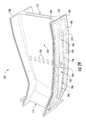
前記複数の一体型燃焼器ノズル(100)は、前記燃焼システム(36)の軸方向の中心線の周囲に環状に並べて配置され、各々の一体型燃焼器ノズル(100)が、翼形の形状を有するタービンノズル(120)を定める下流端部分(114)を有する燃料噴射パネル(110)を含んでおり、
前記複数の燃料噴射モジュール(300)の各々の燃料噴射モジュール(300)は、その少なくとも一部分が、前記複数の一体型燃焼器ノズル(100)のうちの隣り合う一体型燃焼器ノズル(100)のそれぞれのペアの間、かつ前記隣り合う一体型燃焼器ノズル(100)の間に定められるそれぞれの主燃焼ゾーン(102)の下流に配置されている、環状燃焼システム(36)。
[実施態様10]
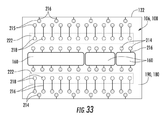
各々の燃料噴射モジュール(300)は、集合管燃料ノズル部分(302)および複数の燃料噴射ランス(304)を備え、前記複数の燃料噴射ランス(304)は、前記複数の一体型燃焼器ノズル(100)のうちのそれぞれの一体型燃焼器ノズル(100)の燃料噴射パネル(110)に流体連通している、実施態様9に記載の環状燃焼システム(36)。
[実施態様11]
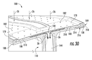
各々の燃料噴射パネル(110)は、正圧側側壁(116)と、負圧側側壁(118)と、前記正圧側側壁(116)と前記負圧側側壁(118)との間に定められた複数の予混合チャネル(132、134)と、前記複数の予混合チャネル(132、134)に流体連通した複数の噴射出口(126、128)とを含み、前記複数の噴射出口(126、128)は、前記正圧側側壁(116)に沿って定められた少なくとも1つの正圧側噴射出口(126)と、前記負圧側側壁(118)に沿って定められた少なくとも1つの負圧側噴射出口(126)とを含む、実施態様9に記載の環状燃焼システム(36)。
[実施態様12]
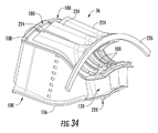
前記複数の一体型燃焼器ノズル(100)の各々の一体型燃焼器ノズル(100)は、内側ライナセグメント(106)および外側ライナセグメント(108)を含み、前記内側ライナセグメント(106)および前記外側ライナセグメント(108)は、前記燃料噴射パネル(110)と一体に形成されている、実施態様9に記載の環状燃焼システム(36)。
[実施態様13]
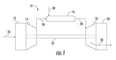
前記環状燃焼システム(36)は、ガスタービン(10)の燃焼部(16)内に配置される、実施態様9に記載の環状燃焼システム(36)。
[実施態様14]
内側ライナ(106)および前記内側ライナ(106)の半径方向外側に配置された外側ライナ(108)と、
複数の燃料ノズルと、
複数の燃料噴射パネル(110)と
を備える環状燃焼システム(36)であって、
前記内側ライナ(106)および前記外側ライナ(108)は、前記燃焼システム(36)の中心線を囲む環状部を前記内側ライナ(106)と前記外側ライナ(108)との間に定めており、前記環状部は、前記環状部の上流端に位置する複数の主燃焼ゾーン(102)と、前記主燃焼ゾーン(102)の下流の複数の二次燃焼ゾーン(104)とを含み、
前記複数の燃料ノズルのうちの少なくとも1つの燃料ノズルは、前記複数の主燃焼ゾーン(102)の各々の主燃焼ゾーン(102)に可燃性混合物を吐出し、
前記複数の燃料噴射パネル(110)の各々の燃料噴射パネル(110)は、隣り合う燃料ノズルの間に少なくとも部分的に配置され、少なくとも1つの二次燃焼ゾーン(104)に可燃性混合物を吐出し、各々の燃料噴射パネル(110)は、隣り合う主燃焼ゾーン(102)を隔て、隣り合う二次燃焼ゾーン(104)も隔てるように、軸方向に下流の方向へと延びており、
各々の燃料噴射パネル(110)は、タービンノズル(120)を定める後端(114)を有している、環状燃焼システム(36)。
[実施態様15]
前記内側ライナ(106)および前記外側ライナ(108)は、分割されている、実施態様14に記載の環状燃焼システム(36)。
[実施態様16]
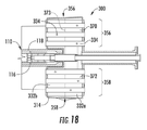
前記複数の燃料ノズルの各々の燃料ノズルは、円周方向において前記複数のパネル燃料インジェクタ(110)のうちの隣り合うパネル壁インジェクタ(110)の間を延びている集合管燃料ノズル(302)であり、各々の集合管燃料ノズル(320)は、前方プレート(316)と、後方プレート(318)と、前記前方プレート(316)と前記後方プレート(318)との間を軸方向に延びている外シュラウド(320)と、前記外シュラウド(320)の内側に定められた燃料プレナム(332)と、前記前方プレート(316)、前記燃料プレナム(332)、および前記後方プレート(318)を通って延びている複数の予混合管(322)とを備えている、実施態様14に記載の環状燃焼システム(36)。
[実施態様17]
各々の燃料ノズルは、半径方向において前記内側ライナ(106)と前記外側ライナ(108)との間を延びている、実施態様16に記載の環状燃焼システム(36)。
[実施態様18]
各々の燃料噴射パネル(110)は、半径方向において前記内側ライナ(106)と前記外側ライナ(108)との間を延びている、実施態様14に記載の環状燃焼システム(36)。
[実施態様19]
前記複数の燃料噴射パネル(110)の各々の燃料噴射パネル(110)は、第1の側壁(116)と、前記第1の側壁(116)の反対側の第2の側壁(118)と、前記第1の側壁(116)と前記第2の側壁(118)とを接続する後端(114)とを備え、前記第1の側壁(116)、前記第2の側壁(118)、および前記後端(114)は、これらの間に予混合空気プレナムおよび燃料プレナムを定め、複数の予混合チャネル(132、134)が、前記第1の側壁(116)と前記第2の側壁(118)との間に配置され、前記複数の予混合チャネル(132、134)の各々の予混合チャネル(132、134)は、前記予混合空気プレナムおよび前記燃料プレナムに連通し、前記第1の側壁(116)および前記第2の側壁(118)の一方に形成された噴射孔(126、128)を有している、実施態様14に記載の環状燃焼システム(36)。
[実施態様20]
前記複数の燃料噴射パネル(110)の各々の燃料噴射パネル(110)における前記複数の予混合チャネル(132、134)は、第1の側の予混合チャネル(132)を含み、前記第1の側の予混合チャネル(132)の前記噴射孔(126)は、それぞれの燃料噴射パネル(110)の前記第1の側壁(116)を貫いて定められている、実施態様19に記載の環状燃焼システム(36)。
12 吸気部
14 圧縮機
16 燃焼部
18 タービン
20 排気部
22 シャフト
24 空気
26 圧縮空気
28 燃料
30 燃焼ガス
32 圧縮機吐出ケーシング
34 高圧プレナム
36 分割型環状燃焼システム
38 中心線
40 端部カバー
100 一体型燃焼器ノズル
102 主燃焼ゾーン
104 二次燃焼ゾーン
106 内側ライナセグメント
107 スロット
108 外側ライナセグメント
109 スロット
110 燃料噴射パネル
112 上流端部分
114 下流端部分
116 第1の(正圧側)側壁
118 第2の(負圧側)側壁
120 タービンノズル
122 軸方向の分割線
124 シールド
126 正圧側噴射出口
128 負圧側噴射出口
130 正圧側噴射面
131 負圧側噴射面
132 正圧側予混合チャネル
134 負圧側予混合チャネル
136 (正圧側予混合チャネルの)一直線の部分
138 (正圧側予混合チャネルの)湾曲した部分
140 (負圧側予混合チャネルの)一直線の部分
142 (負圧側予混合チャネルの)湾曲した部分
144 予混合空気プレナム
146 環状のカラーまたは座
148 ストラット
150 テーパ部
151 中央開口部
152 流路
154 浮動カラー
156 クロスファイヤ管
157 空気供給孔
158 パージ空気孔
160 空気空洞
162 開口部
164 開口部
166 壁
168 開口
170 空気空洞
178 外側衝突パネル
180 (外側ライナセグメントの)外面
182 衝突孔
184 (予混合空気プレナムへの)入口
186 開口部
188 内側衝突パネル
190 (内側ライナセグメントの)外面
192 衝突孔
194 (予混合空気プレナムへの)入口
196 開口部
198 第1の衝突インサート
200 衝突孔
202 第2の衝突インサート
204 空洞
206 (第2の衝突インサートの)半径方向内側の端部
208 (第2の衝突インサートの)半径方向外側の端部
210 冷却流すき間
212 冷却流すき間
214 入口孔
216 マイクロチャネル冷却通路
218 出口孔
220 収集トラフ
222 ダクト
224 取り付けストラット
226 取り付けリング
228 内側フックプレート
230 内側取り付けリング
232 外側二重蛇腹シール
234 (外側二重蛇腹シールの)一端部
236 (外側二重蛇腹シールの)第2の端部
238 内側二重蛇腹シール
240 (内側二重蛇腹シールの)一端部
242 (内側二重蛇腹シールの)第2の端部
244 蛇腹セグメント
246 蛇腹セグメント
248 中間二重蛇腹シール
250 すき間
252 外側フック
254 取り付けほぞ
256 内側スロット
258 外側スロット
260 (内側取り付けリングの)垂直面部分
262 (外側取り付けリングの)垂直面部分
264 内側スロットカバー
266 外側スロットカバー
268 内側前方取り付けリング
269 ほぞ取り付け部
270 スロット
272 締結具
274 ダンパ
300 燃料噴射モジュール
302 燃料ノズル部分
304 燃料噴射ランス
304a (燃料噴射ランスの)半径方向外側のサブセット
304b (燃料噴射ランスの)中間のサブセット
304c (燃料噴射ランスの)半径方向内側のサブセット
306 下流端部分
308 送出先端部
310 噴射ポート
312 蛇腹部分またはカバー
314 ハウジング本体
316 前方プレート
318 後方プレート
320 外周壁
322 管
324 シール
326 (管の)入口
328 (管の)出口
330 予混合通路
332 燃料ノズルプレナム
332a 前方の燃料ノズルプレナム
332b 後方の燃料ノズルプレナム
334 燃料ポート
336 インジェクタ燃料プレナム
338 第1のインジェクタ燃料プレナム
340 (燃料噴射ランスの)第1のサブセット
342 第2のインジェクタ燃料プレナム
344 (燃料噴射ランスの)第2のサブセット
346 導管
348 外側管
350 内側管
352 外側燃料回路
354 内側燃料回路
356 (管の)第1のサブセット
358 (管の)第2のサブセット
360 第1の後方プレート
362 第2の後方プレート
364 イグナイタ
366 シール
368 周壁
370 第1の集合管燃料プレナム
371 壁
372 第2の集合管燃料プレナム
373 壁
374 第1のインジェクタ燃料プレナム
376 第2のインジェクタ燃料プレナム
378 (燃料噴射ランスの)第1のサブセット
380 (燃料噴射ランスの)第2のサブセット
382 燃料導管
384 外側管
386 内側管
388 内側燃料回路
390 外側燃料回路
392 燃料導管
394 外側管
396 内側管
398 内側燃料回路
400 外側燃料回路
402 燃料噴射モジュールセット
404 導管
406 導管
408 燃料供給導管
410 外側導管
412 内側導管
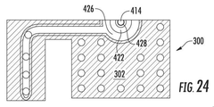
414 液体燃料カートリッジ
416 中間導管
418 空気プレナム
420 開口部
422 内側燃料通路
424 液体燃料
426 外側燃料通路
428 パージ空気通路
430 パージ空気
432 環状のすき間
434 液体燃料
436 液体燃料カートリッジ
437 保護管
438 外側燃料通路
439 環状部
Claims (9)
- 軸方向に多段化された環状燃焼システム(36)のセグメントであって、
内側ライナセグメント(106)と、外側ライナセグメント(108)と、第1の側壁(116)と、第2の側壁(118)と、これらの間に定められた複数の予混合チャネル(132、134)と、前記複数の予混合チャネル(132、134)に流体連通した複数の噴射出口(126、128)と、第1のタービンノズル(120)を定める下流端部分(114)とを含む第1の一体型燃焼器ノズル(100)と、
前記第1の一体型燃焼器ノズル(100)に隣接した第2の一体型燃焼器ノズル(100)であって、内側ライナセグメント(106)と、外側ライナセグメント(108)と、第1の側壁(116)と、第2の側壁(118)と、これらの間に定められた複数の予混合チャネル(132、134)と、前記複数の予混合チャネル(132、134)に流体連通した複数の噴射出口(126、128)と、第2のタービンノズル(120)を定める下流端部分(114)とを含む第2の一体型燃焼器ノズル(100)と、
前記第1の一体型燃焼器ノズル(100)の前記第2の側壁(118)と前記第2の一体型燃焼器ノズル(100)の前記第1の側壁(116)との間に配置された燃料ノズル部分(302)と、燃料供給部ならびに前記第1の一体型燃焼器ノズル(100)の前記複数の予混合チャネル(132、134)および前記第2の一体型燃焼器ノズル(100)の前記複数の予混合チャネル(132、134)のうちの少なくとも1つに流体連通した少なくとも1つの燃料噴射ランス(304)とを含んでいる第1の燃料噴射モジュール(300)と
を備え、
前記燃料ノズル部分(302)からの燃料が前記多段化された環状燃焼システム(36)の第1段に供給され、
前記少なくとも1つの燃料噴射ランス(304)からの燃料が前記多段化された環状燃焼システム(36)の他の段に供給される、環状燃焼システム(36)のセグメント。 - 内側ライナセグメント(106)と、外側ライナセグメント(108)と、第1の側壁(116)と、第2の側壁(118)と、これらの間に定められた複数の予混合チャネル(132、134)と、前記複数の予混合チャネル(132、134)に流体連通した複数の噴射出口(126、128)と、第1のタービンノズル(120)を定める下流端部分(114)とを含む第1の一体型燃焼器ノズル(100)と、
前記第1の一体型燃焼器ノズル(100)に隣接した第2の一体型燃焼器ノズル(100)であって、内側ライナセグメント(106)と、外側ライナセグメント(108)と、第1の側壁(116)と、第2の側壁(118)と、これらの間に定められた複数の予混合チャネル(132、134)と、前記複数の予混合チャネル(132、134)に流体連通した複数の噴射出口(126、128)と、第2のタービンノズル(120)を定める下流端部分(114)とを含む第2の一体型燃焼器ノズル(100)と、
前記第1の一体型燃焼器ノズル(100)の前記第2の側壁(118)と前記第2の一体型燃焼器ノズル(100)の前記第1の側壁(116)との間に配置された燃料ノズル部分(302)と、燃料供給部ならびに前記第1の一体型燃焼器ノズル(100)の前記複数の予混合チャネル(132、134)および前記第2の一体型燃焼器ノズル(100)の前記複数の予混合チャネル(132、134)のうちの少なくとも1つに流体連通した少なくとも1つの燃料噴射ランス(304)とを含んでいる第1の燃料噴射モジュール(300)と
を備え、
前記第1の一体型燃焼器ノズル(100)の前記第1の側壁(116)および前記第2の一体型燃焼器ノズル(100)の前記第1の側壁(116)は、正圧側側壁(116)であり、前記第1の一体型燃焼器ノズル(100)の前記第2の側壁(118)および前記第2の一体型燃焼器ノズル(100)の前記第2の側壁(118)は、負圧側側壁(118)である、環状燃焼システム(36)のセグメント。 - 内側ライナセグメント(106)と、外側ライナセグメント(108)と、第1の側壁(116)と、第2の側壁(118)と、これらの間に定められた複数の予混合チャネル(132、134)と、前記複数の予混合チャネル(132、134)に流体連通した複数の噴射出口(126、128)と、第1のタービンノズル(120)を定める下流端部分(114)とを含む第1の一体型燃焼器ノズル(100)と、
前記第1の一体型燃焼器ノズル(100)に隣接した第2の一体型燃焼器ノズル(100)であって、内側ライナセグメント(106)と、外側ライナセグメント(108)と、第1の側壁(116)と、第2の側壁(118)と、これらの間に定められた複数の予混合チャネル(132、134)と、前記複数の予混合チャネル(132、134)に流体連通した複数の噴射出口(126、128)と、第2のタービンノズル(120)を定める下流端部分(114)とを含む第2の一体型燃焼器ノズル(100)と、
前記第1の一体型燃焼器ノズル(100)の前記第2の側壁(118)と前記第2の一体型燃焼器ノズル(100)の前記第1の側壁(116)との間に配置された燃料ノズル部分(302)と、燃料供給部ならびに前記第1の一体型燃焼器ノズル(100)の前記複数の予混合チャネル(132、134)および前記第2の一体型燃焼器ノズル(100)の前記複数の予混合チャネル(132、134)のうちの少なくとも1つに流体連通した少なくとも1つの燃料噴射ランス(304)とを含んでいる第1の燃料噴射モジュール(300)と、
燃料噴射モジュール(300)の外壁(320)の周囲に延在するシール(324)と、を備える、環状燃焼システム(36)のセグメント。 - 前記少なくとも1つの燃料噴射ランス(304)は、軸方向に多段化された燃焼段の前記軸方向に延びる複数の燃料噴射ランス(304)である、請求項1乃至3のいずれかに記載のセグメント。
- 前記燃料供給部および前記第1の燃料噴射モジュール(300)に結合した導管(346)をさらに備え、前記導管(346)は、前記燃料ノズル部分(302)および前記少なくとも1つの燃料噴射ランス(304)の少なくとも一方に燃料をもたらす、請求項1乃至4のいずれかに記載のセグメント。
- 複数の一体型燃焼器ノズル(100)と、
複数の燃料噴射モジュール(300)と
を備える環状燃焼システム(36)であって、
前記複数の一体型燃焼器ノズル(100)は、前記燃焼システム(36)の軸方向の中心線の周囲に環状に並べて配置され、各々の一体型燃焼器ノズル(100)が、翼形の形状を有するタービンノズル(120)を定める下流端部分(114)を有する燃料噴射パネル(110)を含んでおり、
前記複数の燃料噴射モジュール(300)の各々の燃料噴射モジュール(300)は、その少なくとも一部分が、前記複数の一体型燃焼器ノズル(100)のうちの隣り合う一体型燃焼器ノズル(100)のそれぞれのペアの間、かつ前記隣り合う一体型燃焼器ノズル(100)の間に定められるそれぞれの主燃焼ゾーン(102)の下流に配置されている、環状燃焼システム(36)。 - 各々の燃料噴射モジュール(300)は、集合管燃料ノズル部分(302)および複数の燃料噴射ランス(304)を備え、前記複数の燃料噴射ランス(304)は、前記複数の一体型燃焼器ノズル(100)のうちのそれぞれの一体型燃焼器ノズル(100)の燃料噴射パネル(110)に流体連通している、請求項6に記載の環状燃焼システム(36)。
- 各々の燃料噴射パネル(110)は、正圧側側壁(116)と、負圧側側壁(118)と、前記正圧側側壁(116)と前記負圧側側壁(118)との間に定められた複数の予混合チャネル(132、134)と、前記複数の予混合チャネル(132、134)に流体連通した複数の噴射出口(126、128)とを含み、前記複数の噴射出口(126、128)は、前記正圧側側壁(116)に沿って定められた少なくとも1つの正圧側噴射出口(126)と、前記負圧側側壁(118)に沿って定められた少なくとも1つの負圧側噴射出口(126)とを含む、請求項6または7に記載の環状燃焼システム(36)。
- 前記複数の一体型燃焼器ノズル(100)の各々の一体型燃焼器ノズル(100)は、内側ライナセグメント(106)および外側ライナセグメント(108)を含み、前記内側ライナセグメント(106)および前記外側ライナセグメント(108)は、前記燃料噴射パネル(110)と一体に形成されている、請求項6乃至8のいずれかに記載の環状燃焼システム(36)。
Applications Claiming Priority (5)
| Application Number | Priority Date | Filing Date | Title |
|---|---|---|---|
| US201662313232P | 2016-03-25 | 2016-03-25 | |
| US62/313,232 | 2016-03-25 | ||
| US15/464,394 | 2017-03-21 | ||
| US15/464,394 US10690056B2 (en) | 2016-03-25 | 2017-03-21 | Segmented annular combustion system with axial fuel staging |
| PCT/US2017/024231 WO2017165876A2 (en) | 2016-03-25 | 2017-03-27 | Segmented annular combustion system with axial fuel staging |
Publications (2)
| Publication Number | Publication Date |
|---|---|
| JP2019509460A JP2019509460A (ja) | 2019-04-04 |
| JP6972004B2 true JP6972004B2 (ja) | 2021-11-24 |
Family
ID=59896395
Family Applications (2)
| Application Number | Title | Priority Date | Filing Date |
|---|---|---|---|
| JP2018548828A Active JP6835868B2 (ja) | 2016-03-25 | 2017-03-01 | パネル燃料インジェクタを有する燃焼システム |
| JP2018548827A Active JP6972004B2 (ja) | 2016-03-25 | 2017-03-27 | 軸方向の燃料多段化を備える分割型環状燃焼システム |
Family Applications Before (1)
| Application Number | Title | Priority Date | Filing Date |
|---|---|---|---|
| JP2018548828A Active JP6835868B2 (ja) | 2016-03-25 | 2017-03-01 | パネル燃料インジェクタを有する燃焼システム |
Country Status (6)
| Country | Link |
|---|---|
| US (7) | US10641176B2 (ja) |
| EP (3) | EP4220014B1 (ja) |
| JP (2) | JP6835868B2 (ja) |
| KR (2) | KR102334882B1 (ja) |
| CN (2) | CN109196279B (ja) |
| WO (2) | WO2017165092A1 (ja) |
Families Citing this family (45)
| Publication number | Priority date | Publication date | Assignee | Title |
|---|---|---|---|---|
| CN107420943B (zh) * | 2013-10-18 | 2019-12-06 | 三菱重工业株式会社 | 燃料喷射器 |
| US10641491B2 (en) * | 2016-03-25 | 2020-05-05 | General Electric Company | Cooling of integrated combustor nozzle of segmented annular combustion system |
| US10641176B2 (en) * | 2016-03-25 | 2020-05-05 | General Electric Company | Combustion system with panel fuel injector |
| US11156362B2 (en) | 2016-11-28 | 2021-10-26 | General Electric Company | Combustor with axially staged fuel injection |
| US11248705B2 (en) | 2018-06-19 | 2022-02-15 | General Electric Company | Curved seal with relief cuts for adjacent gas turbine components |
| US11047248B2 (en) | 2018-06-19 | 2021-06-29 | General Electric Company | Curved seal for adjacent gas turbine components |
| US11231175B2 (en) * | 2018-06-19 | 2022-01-25 | General Electric Company | Integrated combustor nozzles with continuously curved liner segments |
| US11248789B2 (en) | 2018-12-07 | 2022-02-15 | Raytheon Technologies Corporation | Gas turbine engine with integral combustion liner and turbine nozzle |
| US11156164B2 (en) | 2019-05-21 | 2021-10-26 | General Electric Company | System and method for high frequency accoustic dampers with caps |
| US11174792B2 (en) | 2019-05-21 | 2021-11-16 | General Electric Company | System and method for high frequency acoustic dampers with baffles |
| JP7145837B2 (ja) * | 2019-10-16 | 2022-10-03 | 株式会社神戸製鋼所 | 反応器及びこれを備えた反応システム |
| CN110919013A (zh) * | 2019-12-11 | 2020-03-27 | 湖南天际智慧材料科技有限公司 | 一种金属粉末火焰球化设备及其加工工艺 |
| US11287134B2 (en) | 2019-12-31 | 2022-03-29 | General Electric Company | Combustor with dual pressure premixing nozzles |
| US11828467B2 (en) | 2019-12-31 | 2023-11-28 | General Electric Company | Fluid mixing apparatus using high- and low-pressure fluid streams |
| US12553385B2 (en) * | 2020-03-30 | 2026-02-17 | Ge Vernova Infrastructure Technology Llc | Compact turbomachine combustor |
| JP7272989B2 (ja) * | 2020-03-31 | 2023-05-12 | 三菱重工業株式会社 | ガスタービン燃焼器、バーナ部品の製造方法 |
| JP7349403B2 (ja) | 2020-04-22 | 2023-09-22 | 三菱重工業株式会社 | バーナー集合体、ガスタービン燃焼器及びガスタービン |
| CN111894738B (zh) * | 2020-07-16 | 2021-09-07 | 北京航空航天大学 | 喷注装置、发动机及喷注装置设计方法 |
| US11994292B2 (en) | 2020-08-31 | 2024-05-28 | General Electric Company | Impingement cooling apparatus for turbomachine |
| US11371702B2 (en) | 2020-08-31 | 2022-06-28 | General Electric Company | Impingement panel for a turbomachine |
| US11614233B2 (en) * | 2020-08-31 | 2023-03-28 | General Electric Company | Impingement panel support structure and method of manufacture |
| US11460191B2 (en) | 2020-08-31 | 2022-10-04 | General Electric Company | Cooling insert for a turbomachine |
| US11994293B2 (en) | 2020-08-31 | 2024-05-28 | General Electric Company | Impingement cooling apparatus support structure and method of manufacture |
| US11668242B2 (en) * | 2020-09-29 | 2023-06-06 | General Electric Company | Fuel injection assembly for a turbomachine |
| US11255545B1 (en) * | 2020-10-26 | 2022-02-22 | General Electric Company | Integrated combustion nozzle having a unified head end |
| CN112555900A (zh) * | 2020-12-09 | 2021-03-26 | 南京航空航天大学 | 用于微型涡喷发动机燃烧室壁面的全覆盖气膜冷却结构 |
| US11371701B1 (en) * | 2021-02-03 | 2022-06-28 | General Electric Company | Combustor for a gas turbine engine |
| KR102429075B1 (ko) * | 2021-02-17 | 2022-08-03 | 두산에너빌리티 주식회사 | 마이크로 믹서 번들 어셈블리, 이를 포함하는 연소기 및 가스 터빈 |
| US11692709B2 (en) | 2021-03-11 | 2023-07-04 | General Electric Company | Gas turbine fuel mixer comprising a plurality of mini tubes for generating a fuel-air mixture |
| US12270543B2 (en) | 2021-08-20 | 2025-04-08 | Rtx Corporation | Multi-function monolithic combustion liner |
| CN114165358B (zh) * | 2021-11-16 | 2023-02-03 | 北京航天动力研究所 | 一种预燃室隔板喷嘴结构 |
| EP4671609A3 (en) | 2021-12-21 | 2026-03-25 | General Electric Company | Fuel nozzle and swirler |
| US11906165B2 (en) | 2021-12-21 | 2024-02-20 | General Electric Company | Gas turbine nozzle having an inner air swirler passage and plural exterior fuel passages |
| JP7780333B2 (ja) * | 2021-12-27 | 2025-12-04 | 川崎重工業株式会社 | 燃焼器のパネル及びそれを備えたガスタービンの燃焼器 |
| US11774100B2 (en) | 2022-01-14 | 2023-10-03 | General Electric Company | Combustor fuel nozzle assembly |
| KR102660055B1 (ko) * | 2022-03-21 | 2024-04-22 | 두산에너빌리티 주식회사 | 연소기용 노즐, 연소기, 및 이를 포함하는 가스 터빈 |
| US11767766B1 (en) | 2022-07-29 | 2023-09-26 | General Electric Company | Turbomachine airfoil having impingement cooling passages |
| CN115355536B (zh) * | 2022-08-17 | 2024-02-02 | 北京理工大学 | 一种适用于燃气轮机的氢氧微混燃烧装置及其使用方法 |
| US12460821B2 (en) | 2023-02-15 | 2025-11-04 | Solar Turbines Incorporated | Fuel injector panels having micromixers |
| CN116146981B (zh) * | 2023-04-17 | 2023-06-16 | 中国空气动力研究与发展中心超高速空气动力研究所 | 一种应用气膜冷却隔板喷嘴的喷注面板 |
| GB202307702D0 (en) * | 2023-05-23 | 2023-07-05 | Rolls Royce Plc | An improved combustor apparatus |
| GB202307700D0 (en) | 2023-05-23 | 2023-07-05 | Rolls Royce Plc | An improved combustor apparatus |
| CN116624894B (zh) * | 2023-05-23 | 2025-06-17 | 哈尔滨工业大学 | 一种紧凑式燃烧室 |
| GB202307701D0 (en) | 2023-05-23 | 2023-07-05 | Rolls Royce Plc | An improved combustor apparatus |
| KR102863421B1 (ko) * | 2023-12-15 | 2025-09-22 | 두산에너빌리티 주식회사 | 연소기용 노즐, 연소기, 및 이를 포함하는 가스 터빈 |
Family Cites Families (142)
| Publication number | Priority date | Publication date | Assignee | Title |
|---|---|---|---|---|
| US2595999A (en) | 1943-11-23 | 1952-05-06 | Westinghouse Electric Corp | Power plant combustion apparatus having apertured combustion chamber walls |
| US2625792A (en) | 1947-09-10 | 1953-01-20 | Rolls Royce | Flame tube having telescoping walls with fluted ends to admit air |
| US3657883A (en) | 1970-07-17 | 1972-04-25 | Westinghouse Electric Corp | Combustion chamber clustering structure |
| US3657882A (en) | 1970-11-13 | 1972-04-25 | Westinghouse Electric Corp | Combustion apparatus |
| US3750398A (en) | 1971-05-17 | 1973-08-07 | Westinghouse Electric Corp | Static seal structure |
| US4614082A (en) | 1972-12-19 | 1986-09-30 | General Electric Company | Combustion chamber construction |
| US4016718A (en) | 1975-07-21 | 1977-04-12 | United Technologies Corporation | Gas turbine engine having an improved transition duct support |
| US4112676A (en) * | 1977-04-05 | 1978-09-12 | Westinghouse Electric Corp. | Hybrid combustor with staged injection of pre-mixed fuel |
| US4195474A (en) | 1977-10-17 | 1980-04-01 | General Electric Company | Liquid-cooled transition member to turbine inlet |
| US4158949A (en) | 1977-11-25 | 1979-06-26 | General Motors Corporation | Segmented annular combustor |
| JPS5554636A (en) | 1978-10-16 | 1980-04-22 | Hitachi Ltd | Combustor of gas turbine |
| US4373327A (en) | 1979-07-04 | 1983-02-15 | Rolls-Royce Limited | Gas turbine engine combustion chambers |
| US4422288A (en) | 1981-03-02 | 1983-12-27 | General Electric Company | Aft mounting system for combustion transition duct members |
| US4413470A (en) | 1981-03-05 | 1983-11-08 | Electric Power Research Institute, Inc. | Catalytic combustion system for a stationary combustion turbine having a transition duct mounted catalytic element |
| US4720970A (en) | 1982-11-05 | 1988-01-26 | The United States Of America As Represented By The Secretary Of The Air Force | Sector airflow variable geometry combustor |
| US4819438A (en) | 1982-12-23 | 1989-04-11 | United States Of America | Steam cooled rich-burn combustor liner |
| DE3317035A1 (de) * | 1983-05-10 | 1984-11-15 | BBC Aktiengesellschaft Brown, Boveri & Cie., Baden, Aargau | Mehrstoffbrenner |
| US4719748A (en) | 1985-05-14 | 1988-01-19 | General Electric Company | Impingement cooled transition duct |
| CA1309873C (en) | 1987-04-01 | 1992-11-10 | Graham P. Butt | Gas turbine combustor transition duct forced convection cooling |
| US4843825A (en) | 1988-05-16 | 1989-07-04 | United Technologies Corporation | Combustor dome heat shield |
| US5297385A (en) | 1988-05-31 | 1994-03-29 | United Technologies Corporation | Combustor |
| JP2820558B2 (ja) * | 1991-10-22 | 1998-11-05 | 三菱重工業株式会社 | 燃焼器とタービン静翼一体型ガスタービン |
| US5239818A (en) | 1992-03-30 | 1993-08-31 | General Electric Company | Dilution pole combustor and method |
| US5237813A (en) | 1992-08-21 | 1993-08-24 | Allied-Signal Inc. | Annular combustor with outer transition liner cooling |
| FR2695460B1 (fr) * | 1992-09-09 | 1994-10-21 | Snecma | Chambre de combustion de turbomachine à plusieurs injecteurs. |
| JP2904701B2 (ja) * | 1993-12-15 | 1999-06-14 | 株式会社日立製作所 | ガスタービン及びガスタービンの燃焼装置 |
| JPH07190370A (ja) * | 1993-12-28 | 1995-07-28 | Hitachi Ltd | ガス燃焼用ハイブリット形燃焼器 |
| US5415000A (en) * | 1994-06-13 | 1995-05-16 | Westinghouse Electric Corporation | Low NOx combustor retro-fit system for gas turbines |
| DE69523545T2 (de) | 1994-12-20 | 2002-05-29 | General Electric Co., Schenectady | Verstärkungrahmen für Gasturbinenbrennkammerendstück |
| US5924288A (en) | 1994-12-22 | 1999-07-20 | General Electric Company | One-piece combustor cowl |
| US5836164A (en) * | 1995-01-30 | 1998-11-17 | Hitachi, Ltd. | Gas turbine combustor |
| US6058710A (en) * | 1995-03-08 | 2000-05-09 | Bmw Rolls-Royce Gmbh | Axially staged annular combustion chamber of a gas turbine |
| US5749229A (en) | 1995-10-13 | 1998-05-12 | General Electric Company | Thermal spreading combustor liner |
| US5826430A (en) | 1996-04-23 | 1998-10-27 | Westinghouse Electric Corporation | Fuel heating system used in conjunction with steam cooled combustors and transitions |
| US6047550A (en) * | 1996-05-02 | 2000-04-11 | General Electric Co. | Premixing dry low NOx emissions combustor with lean direct injection of gas fuel |
| JP3276289B2 (ja) | 1996-05-13 | 2002-04-22 | 三菱重工業株式会社 | ガスタービン燃焼器 |
| JP3500020B2 (ja) | 1996-11-29 | 2004-02-23 | 三菱重工業株式会社 | 蒸気冷却ガスタービンシステム |
| DE19654472A1 (de) | 1996-12-27 | 1998-07-02 | Asea Brown Boveri | Verfahren zur Kühlung von thermisch hochbelasteten Aggregaten einer Gasturbogruppe |
| US5906093A (en) | 1997-02-21 | 1999-05-25 | Siemens Westinghouse Power Corporation | Gas turbine combustor transition |
| DE29714742U1 (de) | 1997-08-18 | 1998-12-17 | Siemens AG, 80333 München | Hitzeschildkomponente mit Kühlfluidrückführung und Hitzeschildanordnung für eine heißgasführende Komponente |
| US6116013A (en) | 1998-01-02 | 2000-09-12 | Siemens Westinghouse Power Corporation | Bolted gas turbine combustor transition coupling |
| EP1064498B1 (de) | 1998-03-20 | 2002-11-13 | Siemens Aktiengesellschaft | Gasturbinenbrenner |
| US6098397A (en) | 1998-06-08 | 2000-08-08 | Caterpillar Inc. | Combustor for a low-emissions gas turbine engine |
| US6082111A (en) | 1998-06-11 | 2000-07-04 | Siemens Westinghouse Power Corporation | Annular premix section for dry low-NOx combustors |
| US6339923B1 (en) * | 1998-10-09 | 2002-01-22 | General Electric Company | Fuel air mixer for a radial dome in a gas turbine engine combustor |
| JP2001041005A (ja) | 1999-08-02 | 2001-02-13 | Tohoku Electric Power Co Inc | ガスタービン蒸気冷却燃焼器の配管サポート |
| US6412268B1 (en) | 2000-04-06 | 2002-07-02 | General Electric Company | Cooling air recycling for gas turbine transition duct end frame and related method |
| JP2001289062A (ja) | 2000-04-07 | 2001-10-19 | Mitsubishi Heavy Ind Ltd | ガスタービン燃焼器の壁面冷却構造 |
| IT1317978B1 (it) | 2000-06-16 | 2003-07-21 | Nuovo Pignone Spa | Transition piece per camere di combustione di turbine a gas nonanulari. |
| JP3846169B2 (ja) | 2000-09-14 | 2006-11-15 | 株式会社日立製作所 | ガスタービンの補修方法 |
| US6345494B1 (en) | 2000-09-20 | 2002-02-12 | Siemens Westinghouse Power Corporation | Side seal for combustor transitions |
| US6298656B1 (en) | 2000-09-29 | 2001-10-09 | Siemens Westinghouse Power Corporation | Compressed air steam generator for cooling combustion turbine transition section |
| JP2002206743A (ja) | 2000-12-28 | 2002-07-26 | Toyota Central Res & Dev Lab Inc | 予混合燃焼器 |
| US6450762B1 (en) | 2001-01-31 | 2002-09-17 | General Electric Company | Integral aft seal for turbine applications |
| JP2002243154A (ja) | 2001-02-16 | 2002-08-28 | Mitsubishi Heavy Ind Ltd | ガスタービン燃焼器尾筒出口構造及びガスタービン燃焼器 |
| JP4008212B2 (ja) | 2001-06-29 | 2007-11-14 | 三菱重工業株式会社 | フランジ付中空構造物 |
| US6652220B2 (en) | 2001-11-15 | 2003-11-25 | General Electric Company | Methods and apparatus for cooling gas turbine nozzles |
| US6568187B1 (en) | 2001-12-10 | 2003-05-27 | Power Systems Mfg, Llc | Effusion cooled transition duct |
| JP4134311B2 (ja) * | 2002-03-08 | 2008-08-20 | 独立行政法人 宇宙航空研究開発機構 | ガスタービン燃焼器 |
| US6655147B2 (en) | 2002-04-10 | 2003-12-02 | General Electric Company | Annular one-piece corrugated liner for combustor of a gas turbine engine |
| US6619915B1 (en) | 2002-08-06 | 2003-09-16 | Power Systems Mfg, Llc | Thermally free aft frame for a transition duct |
| US6644032B1 (en) | 2002-10-22 | 2003-11-11 | Power Systems Mfg, Llc | Transition duct with enhanced profile optimization |
| GB2402715B (en) | 2003-06-10 | 2006-06-14 | Rolls Royce Plc | Gas turbine aerofoil |
| US7010921B2 (en) | 2004-06-01 | 2006-03-14 | General Electric Company | Method and apparatus for cooling combustor liner and transition piece of a gas turbine |
| US7377036B2 (en) * | 2004-10-05 | 2008-05-27 | General Electric Company | Methods for tuning fuel injection assemblies for a gas turbine fuel nozzle |
| US7310938B2 (en) | 2004-12-16 | 2007-12-25 | Siemens Power Generation, Inc. | Cooled gas turbine transition duct |
| US8015818B2 (en) | 2005-02-22 | 2011-09-13 | Siemens Energy, Inc. | Cooled transition duct for a gas turbine engine |
| US7437876B2 (en) * | 2005-03-25 | 2008-10-21 | General Electric Company | Augmenter swirler pilot |
| EP1875501A1 (en) | 2005-04-13 | 2008-01-09 | Freescale Semiconductor, Inc. | Protection of an integrated circuit and method therefor |
| US7779636B2 (en) | 2005-05-04 | 2010-08-24 | Delavan Inc | Lean direct injection atomizer for gas turbine engines |
| US7334960B2 (en) | 2005-06-23 | 2008-02-26 | Siemens Power Generation, Inc. | Attachment device for removable components in hot gas paths in a turbine engine |
| US7886517B2 (en) | 2007-05-09 | 2011-02-15 | Siemens Energy, Inc. | Impingement jets coupled to cooling channels for transition cooling |
| US7836703B2 (en) * | 2007-06-20 | 2010-11-23 | General Electric Company | Reciprocal cooled turbine nozzle |
| US8011188B2 (en) * | 2007-08-31 | 2011-09-06 | General Electric Company | Augmentor with trapped vortex cavity pilot |
| US8387398B2 (en) | 2007-09-14 | 2013-03-05 | Siemens Energy, Inc. | Apparatus and method for controlling the secondary injection of fuel |
| US7665309B2 (en) | 2007-09-14 | 2010-02-23 | Siemens Energy, Inc. | Secondary fuel delivery system |
| JP4823186B2 (ja) * | 2007-09-25 | 2011-11-24 | 三菱重工業株式会社 | ガスタービン燃焼器 |
| US8151570B2 (en) | 2007-12-06 | 2012-04-10 | Alstom Technology Ltd | Transition duct cooling feed tubes |
| US8104292B2 (en) | 2007-12-17 | 2012-01-31 | General Electric Company | Duplex turbine shroud |
| US7874138B2 (en) | 2008-09-11 | 2011-01-25 | Siemens Energy, Inc. | Segmented annular combustor |
| US8272218B2 (en) | 2008-09-24 | 2012-09-25 | Siemens Energy, Inc. | Spiral cooled fuel nozzle |
| US8375726B2 (en) | 2008-09-24 | 2013-02-19 | Siemens Energy, Inc. | Combustor assembly in a gas turbine engine |
| US8230688B2 (en) | 2008-09-29 | 2012-07-31 | Siemens Energy, Inc. | Modular transvane assembly |
| KR101346566B1 (ko) | 2008-10-08 | 2014-01-02 | 미츠비시 쥬고교 가부시키가이샤 | 가스 터빈 및 그 운전 방법 |
| US8549861B2 (en) | 2009-01-07 | 2013-10-08 | General Electric Company | Method and apparatus to enhance transition duct cooling in a gas turbine engine |
| US20100192582A1 (en) * | 2009-02-04 | 2010-08-05 | Robert Bland | Combustor nozzle |
| US8851402B2 (en) * | 2009-02-12 | 2014-10-07 | General Electric Company | Fuel injection for gas turbine combustors |
| US8307657B2 (en) * | 2009-03-10 | 2012-11-13 | General Electric Company | Combustor liner cooling system |
| US8904799B2 (en) | 2009-05-25 | 2014-12-09 | Majed Toqan | Tangential combustor with vaneless turbine for use on gas turbine engines |
| US8616002B2 (en) * | 2009-07-23 | 2013-12-31 | General Electric Company | Gas turbine premixing systems |
| US8281594B2 (en) | 2009-09-08 | 2012-10-09 | Siemens Energy, Inc. | Fuel injector for use in a gas turbine engine |
| JP5103454B2 (ja) * | 2009-09-30 | 2012-12-19 | 株式会社日立製作所 | 燃焼器 |
| WO2011054760A1 (en) * | 2009-11-07 | 2011-05-12 | Alstom Technology Ltd | A cooling scheme for an increased gas turbine efficiency |
| JP5479058B2 (ja) * | 2009-12-07 | 2014-04-23 | 三菱重工業株式会社 | 燃焼器とタービン部との連通構造、および、ガスタービン |
| US8752386B2 (en) | 2010-05-25 | 2014-06-17 | Siemens Energy, Inc. | Air/fuel supply system for use in a gas turbine engine |
| RU2531110C2 (ru) * | 2010-06-29 | 2014-10-20 | Дженерал Электрик Компани | Газотурбинная установка и установка, содержащая лопатки-форсунки (варианты) |
| US8261555B2 (en) * | 2010-07-08 | 2012-09-11 | General Electric Company | Injection nozzle for a turbomachine |
| US8499566B2 (en) | 2010-08-12 | 2013-08-06 | General Electric Company | Combustor liner cooling system |
| JP5156066B2 (ja) | 2010-08-27 | 2013-03-06 | 株式会社日立製作所 | ガスタービン燃焼器 |
| EP2434222B1 (en) * | 2010-09-24 | 2019-02-27 | Ansaldo Energia IP UK Limited | Method for operating a combustion chamber |
| JP5653705B2 (ja) | 2010-09-30 | 2015-01-14 | 三菱重工業株式会社 | 回収式空気冷却ガスタービン燃焼器冷却構造 |
| EP2436977A1 (en) * | 2010-09-30 | 2012-04-04 | Siemens Aktiengesellschaft | Burner for a gas turbine |
| US8464537B2 (en) * | 2010-10-21 | 2013-06-18 | General Electric Company | Fuel nozzle for combustor |
| US8387391B2 (en) | 2010-12-17 | 2013-03-05 | General Electric Company | Aerodynamically enhanced fuel nozzle |
| US8726668B2 (en) | 2010-12-17 | 2014-05-20 | General Electric Company | Fuel atomization dual orifice fuel nozzle |
| US20120151928A1 (en) | 2010-12-17 | 2012-06-21 | Nayan Vinodbhai Patel | Cooling flowpath dirt deflector in fuel nozzle |
| KR101471311B1 (ko) | 2011-03-16 | 2014-12-09 | 미츠비시 쥬고교 가부시키가이샤 | 가스 터빈 연소기 및 가스 터빈 |
| US8893382B2 (en) * | 2011-09-30 | 2014-11-25 | General Electric Company | Combustion system and method of assembling the same |
| US9188335B2 (en) * | 2011-10-26 | 2015-11-17 | General Electric Company | System and method for reducing combustion dynamics and NOx in a combustor |
| FR2982008B1 (fr) | 2011-10-26 | 2013-12-13 | Snecma | Paroi annulaire de chambre de combustion a refroidissement ameliore au niveau des trous primaires et de dilution |
| EP2613080A1 (en) | 2012-01-05 | 2013-07-10 | Siemens Aktiengesellschaft | Combustion chamber of an annular combustor for a gas turbine |
| US9016039B2 (en) * | 2012-04-05 | 2015-04-28 | General Electric Company | Combustor and method for supplying fuel to a combustor |
| US9335050B2 (en) * | 2012-09-26 | 2016-05-10 | United Technologies Corporation | Gas turbine engine combustor |
| US9599343B2 (en) * | 2012-11-28 | 2017-03-21 | General Electric Company | Fuel nozzle for use in a turbine engine and method of assembly |
| US9366437B2 (en) * | 2012-12-20 | 2016-06-14 | General Electric Company | System for reducing flame holding within a combustor |
| US9435539B2 (en) * | 2013-02-06 | 2016-09-06 | General Electric Company | Variable volume combustor with pre-nozzle fuel injection system |
| CN105229379B (zh) * | 2013-03-13 | 2017-06-13 | 三菱日立电力系统株式会社 | 燃气涡轮燃烧器 |
| US9546789B2 (en) | 2013-03-15 | 2017-01-17 | General Electric Company | System having a multi-tube fuel nozzle |
| US9458767B2 (en) * | 2013-03-18 | 2016-10-04 | General Electric Company | Fuel injection insert for a turbine nozzle segment |
| EP2796789B1 (en) * | 2013-04-26 | 2017-03-01 | General Electric Technology GmbH | Can combustor for a can-annular combustor arrangement in a gas turbine |
| WO2014191495A1 (de) | 2013-05-31 | 2014-12-04 | Siemens Aktiengesellschaft | Gasturbinen-ringbrennkammer mit tangentialeindüsung als späte mager-einspritzung |
| EP3008391B1 (en) * | 2013-06-11 | 2020-05-06 | United Technologies Corporation | Combustor with axial staging for a gas turbine engine |
| EP2837888A1 (en) * | 2013-08-15 | 2015-02-18 | Alstom Technology Ltd | Sequential combustion with dilution gas mixer |
| US9476592B2 (en) * | 2013-09-19 | 2016-10-25 | General Electric Company | System for injecting fuel in a gas turbine combustor |
| CN107420943B (zh) * | 2013-10-18 | 2019-12-06 | 三菱重工业株式会社 | 燃料喷射器 |
| US9518478B2 (en) * | 2013-10-28 | 2016-12-13 | General Electric Company | Microchannel exhaust for cooling and/or purging gas turbine segment gaps |
| US20150159877A1 (en) * | 2013-12-06 | 2015-06-11 | General Electric Company | Late lean injection manifold mixing system |
| US9650958B2 (en) * | 2014-07-17 | 2017-05-16 | General Electric Company | Combustor cap with cooling passage |
| US10480791B2 (en) | 2014-07-31 | 2019-11-19 | General Electric Company | Fuel injector to facilitate reduced NOx emissions in a combustor system |
| US9534786B2 (en) * | 2014-08-08 | 2017-01-03 | Pratt & Whitney Canada Corp. | Combustor heat shield |
| EP3081862B1 (en) * | 2015-04-13 | 2020-08-19 | Ansaldo Energia Switzerland AG | Vortex generating arrangement for a pre-mixing burner of a gas turbine and gas turbine with such vortex generating arrangement |
| US10267521B2 (en) * | 2015-04-13 | 2019-04-23 | Pratt & Whitney Canada Corp. | Combustor heat shield |
| US10830442B2 (en) * | 2016-03-25 | 2020-11-10 | General Electric Company | Segmented annular combustion system with dual fuel capability |
| US10641491B2 (en) * | 2016-03-25 | 2020-05-05 | General Electric Company | Cooling of integrated combustor nozzle of segmented annular combustion system |
| US10584876B2 (en) * | 2016-03-25 | 2020-03-10 | General Electric Company | Micro-channel cooling of integrated combustor nozzle of a segmented annular combustion system |
| US11428413B2 (en) * | 2016-03-25 | 2022-08-30 | General Electric Company | Fuel injection module for segmented annular combustion system |
| US10641176B2 (en) * | 2016-03-25 | 2020-05-05 | General Electric Company | Combustion system with panel fuel injector |
| US10563869B2 (en) * | 2016-03-25 | 2020-02-18 | General Electric Company | Operation and turndown of a segmented annular combustion system |
| US10605459B2 (en) * | 2016-03-25 | 2020-03-31 | General Electric Company | Integrated combustor nozzle for a segmented annular combustion system |
| US10584880B2 (en) * | 2016-03-25 | 2020-03-10 | General Electric Company | Mounting of integrated combustor nozzles in a segmented annular combustion system |
| US10520194B2 (en) * | 2016-03-25 | 2019-12-31 | General Electric Company | Radially stacked fuel injection module for a segmented annular combustion system |
| US10690350B2 (en) * | 2016-11-28 | 2020-06-23 | General Electric Company | Combustor with axially staged fuel injection |
-
2017
- 2017-02-24 US US15/442,255 patent/US10641176B2/en active Active
- 2017-02-24 US US15/442,227 patent/US10641175B2/en active Active
- 2017-02-24 US US15/442,203 patent/US11002190B2/en active Active
- 2017-02-24 US US15/442,269 patent/US10584638B2/en active Active
- 2017-02-24 US US15/442,292 patent/US10655541B2/en active Active
- 2017-02-24 US US15/442,171 patent/US10724441B2/en active Active
- 2017-03-01 JP JP2018548828A patent/JP6835868B2/ja active Active
- 2017-03-01 EP EP23020043.8A patent/EP4220014B1/en active Active
- 2017-03-01 WO PCT/US2017/020105 patent/WO2017165092A1/en not_active Ceased
- 2017-03-01 EP EP17711434.5A patent/EP3433539B1/en active Active
- 2017-03-01 CN CN201780032272.1A patent/CN109196279B/zh active Active
- 2017-03-01 KR KR1020187030782A patent/KR102334882B1/ko active Active
- 2017-03-21 US US15/464,394 patent/US10690056B2/en active Active
- 2017-03-27 CN CN201780019691.1A patent/CN109477638B/zh active Active
- 2017-03-27 EP EP17715619.7A patent/EP3433541B1/en active Active
- 2017-03-27 WO PCT/US2017/024231 patent/WO2017165876A2/en not_active Ceased
- 2017-03-27 JP JP2018548827A patent/JP6972004B2/ja active Active
- 2017-03-27 KR KR1020187030823A patent/KR102325910B1/ko active Active
Also Published As
Similar Documents
| Publication | Publication Date | Title |
|---|---|---|
| JP6972004B2 (ja) | 軸方向の燃料多段化を備える分割型環状燃焼システム | |
| JP6894447B2 (ja) | 分割型環状燃焼システムのための一体型燃焼器ノズル | |
| JP6920018B2 (ja) | セグメント型の環状燃焼システム用の燃料噴射モジュール | |
| US10830442B2 (en) | Segmented annular combustion system with dual fuel capability | |
| US10584876B2 (en) | Micro-channel cooling of integrated combustor nozzle of a segmented annular combustion system | |
| US10584880B2 (en) | Mounting of integrated combustor nozzles in a segmented annular combustion system | |
| CN108870442B (zh) | 双燃料喷射器和在燃气涡轮燃烧器中的使用方法 | |
| US10563869B2 (en) | Operation and turndown of a segmented annular combustion system | |
| US10520194B2 (en) | Radially stacked fuel injection module for a segmented annular combustion system | |
| US10641491B2 (en) | Cooling of integrated combustor nozzle of segmented annular combustion system |
Legal Events
| Date | Code | Title | Description |
|---|---|---|---|
| RD04 | Notification of resignation of power of attorney |
Free format text: JAPANESE INTERMEDIATE CODE: A7424 Effective date: 20190527 |
|
| A621 | Written request for application examination |
Free format text: JAPANESE INTERMEDIATE CODE: A621 Effective date: 20200323 |
|
| A131 | Notification of reasons for refusal |
Free format text: JAPANESE INTERMEDIATE CODE: A131 Effective date: 20210205 |
|
| A977 | Report on retrieval |
Free format text: JAPANESE INTERMEDIATE CODE: A971007 Effective date: 20210204 |
|
| A601 | Written request for extension of time |
Free format text: JAPANESE INTERMEDIATE CODE: A601 Effective date: 20210430 |
|
| A521 | Request for written amendment filed |
Free format text: JAPANESE INTERMEDIATE CODE: A523 Effective date: 20210721 |
|
| TRDD | Decision of grant or rejection written | ||
| A01 | Written decision to grant a patent or to grant a registration (utility model) |
Free format text: JAPANESE INTERMEDIATE CODE: A01 Effective date: 20211005 |
|
| A61 | First payment of annual fees (during grant procedure) |
Free format text: JAPANESE INTERMEDIATE CODE: A61 Effective date: 20211102 |
|
| R150 | Certificate of patent or registration of utility model |
Ref document number: 6972004 Country of ref document: JP Free format text: JAPANESE INTERMEDIATE CODE: R150 |
|
| S111 | Request for change of ownership or part of ownership |
Free format text: JAPANESE INTERMEDIATE CODE: R313113 |
|
| R350 | Written notification of registration of transfer |
Free format text: JAPANESE INTERMEDIATE CODE: R350 |
|
| R250 | Receipt of annual fees |
Free format text: JAPANESE INTERMEDIATE CODE: R250 |