JP6972004B2 - Split-type annular combustion system with multi-stage fuel in the axial direction - Google Patents
Split-type annular combustion system with multi-stage fuel in the axial direction Download PDFInfo
- Publication number
- JP6972004B2 JP6972004B2 JP2018548827A JP2018548827A JP6972004B2 JP 6972004 B2 JP6972004 B2 JP 6972004B2 JP 2018548827 A JP2018548827 A JP 2018548827A JP 2018548827 A JP2018548827 A JP 2018548827A JP 6972004 B2 JP6972004 B2 JP 6972004B2
- Authority
- JP
- Japan
- Prior art keywords
- fuel
- fuel injection
- nozzle
- side wall
- integrated combustor
- Prior art date
- Legal status (The legal status is an assumption and is not a legal conclusion. Google has not performed a legal analysis and makes no representation as to the accuracy of the status listed.)
- Active
Links
Images


Classifications
-
- F—MECHANICAL ENGINEERING; LIGHTING; HEATING; WEAPONS; BLASTING
- F23—COMBUSTION APPARATUS; COMBUSTION PROCESSES
- F23R—GENERATING COMBUSTION PRODUCTS OF HIGH PRESSURE OR HIGH VELOCITY, e.g. GAS-TURBINE COMBUSTION CHAMBERS
- F23R3/00—Continuous combustion chambers using liquid or gaseous fuel
- F23R3/28—Continuous combustion chambers using liquid or gaseous fuel characterised by the fuel supply
- F23R3/34—Feeding into different combustion zones
-
- F—MECHANICAL ENGINEERING; LIGHTING; HEATING; WEAPONS; BLASTING
- F23—COMBUSTION APPARATUS; COMBUSTION PROCESSES
- F23R—GENERATING COMBUSTION PRODUCTS OF HIGH PRESSURE OR HIGH VELOCITY, e.g. GAS-TURBINE COMBUSTION CHAMBERS
- F23R3/00—Continuous combustion chambers using liquid or gaseous fuel
- F23R3/28—Continuous combustion chambers using liquid or gaseous fuel characterised by the fuel supply
- F23R3/283—Attaching or cooling of fuel injecting means including supports for fuel injectors, stems, or lances
-
- F—MECHANICAL ENGINEERING; LIGHTING; HEATING; WEAPONS; BLASTING
- F02—COMBUSTION ENGINES; HOT-GAS OR COMBUSTION-PRODUCT ENGINE PLANTS
- F02C—GAS-TURBINE PLANTS; AIR INTAKES FOR JET-PROPULSION PLANTS; CONTROLLING FUEL SUPPLY IN AIR-BREATHING JET-PROPULSION PLANTS
- F02C7/00—Features, components parts, details or accessories, not provided for in, or of interest apart form groups F02C1/00 - F02C6/00; Air intakes for jet-propulsion plants
- F02C7/12—Cooling of plants
- F02C7/16—Cooling of plants characterised by cooling medium
- F02C7/18—Cooling of plants characterised by cooling medium the medium being gaseous, e.g. air
-
- F—MECHANICAL ENGINEERING; LIGHTING; HEATING; WEAPONS; BLASTING
- F02—COMBUSTION ENGINES; HOT-GAS OR COMBUSTION-PRODUCT ENGINE PLANTS
- F02C—GAS-TURBINE PLANTS; AIR INTAKES FOR JET-PROPULSION PLANTS; CONTROLLING FUEL SUPPLY IN AIR-BREATHING JET-PROPULSION PLANTS
- F02C3/00—Gas-turbine plants characterised by the use of combustion products as the working fluid
- F02C3/04—Gas-turbine plants characterised by the use of combustion products as the working fluid having a turbine driving a compressor
-
- F—MECHANICAL ENGINEERING; LIGHTING; HEATING; WEAPONS; BLASTING
- F02—COMBUSTION ENGINES; HOT-GAS OR COMBUSTION-PRODUCT ENGINE PLANTS
- F02C—GAS-TURBINE PLANTS; AIR INTAKES FOR JET-PROPULSION PLANTS; CONTROLLING FUEL SUPPLY IN AIR-BREATHING JET-PROPULSION PLANTS
- F02C7/00—Features, components parts, details or accessories, not provided for in, or of interest apart form groups F02C1/00 - F02C6/00; Air intakes for jet-propulsion plants
- F02C7/22—Fuel supply systems
- F02C7/222—Fuel flow conduits, e.g. manifolds
-
- F—MECHANICAL ENGINEERING; LIGHTING; HEATING; WEAPONS; BLASTING
- F23—COMBUSTION APPARATUS; COMBUSTION PROCESSES
- F23R—GENERATING COMBUSTION PRODUCTS OF HIGH PRESSURE OR HIGH VELOCITY, e.g. GAS-TURBINE COMBUSTION CHAMBERS
- F23R3/00—Continuous combustion chambers using liquid or gaseous fuel
- F23R3/002—Wall structures
-
- F—MECHANICAL ENGINEERING; LIGHTING; HEATING; WEAPONS; BLASTING
- F23—COMBUSTION APPARATUS; COMBUSTION PROCESSES
- F23R—GENERATING COMBUSTION PRODUCTS OF HIGH PRESSURE OR HIGH VELOCITY, e.g. GAS-TURBINE COMBUSTION CHAMBERS
- F23R3/00—Continuous combustion chambers using liquid or gaseous fuel
- F23R3/005—Combined with pressure or heat exchangers
-
- F—MECHANICAL ENGINEERING; LIGHTING; HEATING; WEAPONS; BLASTING
- F23—COMBUSTION APPARATUS; COMBUSTION PROCESSES
- F23R—GENERATING COMBUSTION PRODUCTS OF HIGH PRESSURE OR HIGH VELOCITY, e.g. GAS-TURBINE COMBUSTION CHAMBERS
- F23R3/00—Continuous combustion chambers using liquid or gaseous fuel
- F23R3/02—Continuous combustion chambers using liquid or gaseous fuel characterised by the air-flow or gas-flow configuration
- F23R3/04—Air inlet arrangements
- F23R3/06—Arrangement of apertures along the flame tube
-
- F—MECHANICAL ENGINEERING; LIGHTING; HEATING; WEAPONS; BLASTING
- F23—COMBUSTION APPARATUS; COMBUSTION PROCESSES
- F23R—GENERATING COMBUSTION PRODUCTS OF HIGH PRESSURE OR HIGH VELOCITY, e.g. GAS-TURBINE COMBUSTION CHAMBERS
- F23R3/00—Continuous combustion chambers using liquid or gaseous fuel
- F23R3/02—Continuous combustion chambers using liquid or gaseous fuel characterised by the air-flow or gas-flow configuration
- F23R3/04—Air inlet arrangements
- F23R3/10—Air inlet arrangements for primary air
-
- F—MECHANICAL ENGINEERING; LIGHTING; HEATING; WEAPONS; BLASTING
- F23—COMBUSTION APPARATUS; COMBUSTION PROCESSES
- F23R—GENERATING COMBUSTION PRODUCTS OF HIGH PRESSURE OR HIGH VELOCITY, e.g. GAS-TURBINE COMBUSTION CHAMBERS
- F23R3/00—Continuous combustion chambers using liquid or gaseous fuel
- F23R3/28—Continuous combustion chambers using liquid or gaseous fuel characterised by the fuel supply
- F23R3/286—Continuous combustion chambers using liquid or gaseous fuel characterised by the fuel supply having fuel-air premixing devices
-
- F—MECHANICAL ENGINEERING; LIGHTING; HEATING; WEAPONS; BLASTING
- F23—COMBUSTION APPARATUS; COMBUSTION PROCESSES
- F23R—GENERATING COMBUSTION PRODUCTS OF HIGH PRESSURE OR HIGH VELOCITY, e.g. GAS-TURBINE COMBUSTION CHAMBERS
- F23R3/00—Continuous combustion chambers using liquid or gaseous fuel
- F23R3/28—Continuous combustion chambers using liquid or gaseous fuel characterised by the fuel supply
- F23R3/34—Feeding into different combustion zones
- F23R3/346—Feeding into different combustion zones for staged combustion
-
- F—MECHANICAL ENGINEERING; LIGHTING; HEATING; WEAPONS; BLASTING
- F05—INDEXING SCHEMES RELATING TO ENGINES OR PUMPS IN VARIOUS SUBCLASSES OF CLASSES F01-F04
- F05D—INDEXING SCHEME FOR ASPECTS RELATING TO NON-POSITIVE-DISPLACEMENT MACHINES OR ENGINES, GAS-TURBINES OR JET-PROPULSION PLANTS
- F05D2220/00—Application
- F05D2220/30—Application in turbines
- F05D2220/32—Application in turbines in gas turbines
-
- F—MECHANICAL ENGINEERING; LIGHTING; HEATING; WEAPONS; BLASTING
- F05—INDEXING SCHEMES RELATING TO ENGINES OR PUMPS IN VARIOUS SUBCLASSES OF CLASSES F01-F04
- F05D—INDEXING SCHEME FOR ASPECTS RELATING TO NON-POSITIVE-DISPLACEMENT MACHINES OR ENGINES, GAS-TURBINES OR JET-PROPULSION PLANTS
- F05D2240/00—Components
- F05D2240/35—Combustors or associated equipment
-
- F—MECHANICAL ENGINEERING; LIGHTING; HEATING; WEAPONS; BLASTING
- F05—INDEXING SCHEMES RELATING TO ENGINES OR PUMPS IN VARIOUS SUBCLASSES OF CLASSES F01-F04
- F05D—INDEXING SCHEME FOR ASPECTS RELATING TO NON-POSITIVE-DISPLACEMENT MACHINES OR ENGINES, GAS-TURBINES OR JET-PROPULSION PLANTS
- F05D2260/00—Function
- F05D2260/20—Heat transfer, e.g. cooling
- F05D2260/201—Heat transfer, e.g. cooling by impingement of a fluid
-
- F—MECHANICAL ENGINEERING; LIGHTING; HEATING; WEAPONS; BLASTING
- F05—INDEXING SCHEMES RELATING TO ENGINES OR PUMPS IN VARIOUS SUBCLASSES OF CLASSES F01-F04
- F05D—INDEXING SCHEME FOR ASPECTS RELATING TO NON-POSITIVE-DISPLACEMENT MACHINES OR ENGINES, GAS-TURBINES OR JET-PROPULSION PLANTS
- F05D2260/00—Function
- F05D2260/20—Heat transfer, e.g. cooling
- F05D2260/202—Heat transfer, e.g. cooling by film cooling
Landscapes
- Engineering & Computer Science (AREA)
- Chemical & Material Sciences (AREA)
- Combustion & Propulsion (AREA)
- Mechanical Engineering (AREA)
- General Engineering & Computer Science (AREA)
- Gas Burners (AREA)
Description
本明細書に開示される主題は、ガスタービン用の環状燃焼システムに関する。より具体的には、本開示は、ガスタービン用の軸方向の燃料多段化を備える分割型環状燃焼システムに関する。 The subject matter disclosed herein relates to an annular combustion system for gas turbines. More specifically, the present disclosure relates to a split ring combustion system with axial fuel multistage for gas turbines.
産業用のガスタービン燃焼システムは、通常は、炭化水素燃料を燃焼させ、窒素酸化物(NOx)および一酸化炭素(CO)などの大気汚染排出物を発生させる。ガスタービンにおける窒素分子の酸化は、燃焼器内に位置するガスの温度、ならびに燃焼器内の最も高温の領域に位置する反応物質の滞留時間に依存する。したがって、ガスタービンにおいて発生するNOxの量を、燃焼器の温度をNOxの発生温度よりも低く保ち、あるいは燃焼器における反応物質の滞留時間を制限することにより、減少させ、あるいは抑制することが可能である。 Industrial gas turbine combustion systems typically burn hydrocarbon fuels to generate air pollutant emissions such as nitrogen oxides (NOx) and carbon monoxide (CO). Oxidation of nitrogen molecules in a gas turbine depends on the temperature of the gas located in the combustor and the residence time of the reactants located in the hottest region of the combustor. Therefore, the amount of NOx generated in the gas turbine can be reduced or suppressed by keeping the temperature of the combustor lower than the temperature at which NOx is generated, or by limiting the residence time of the reactants in the combustor. Is.
燃焼器の温度を抑えるための1つの手法は、燃焼に先立って燃料および空気をあらかじめ混合して燃料−空気混合物を生成することを含む。この手法は、燃料インジェクタの軸方向の多段化を含むことができ、そのような多段化においては、第1の燃料−空気混合物が、燃焼器の第1の燃焼ゾーンまたは主燃焼ゾーンにおいて噴射および点火され、高エネルギの燃焼ガスの主たる流れを生じさせ、第2の燃料−空気混合物が、主燃焼ゾーンの下流に位置する半径方向に向けられて周状に間隔を空けつつ配置された複数の燃料インジェクタまたは軸方向に多段化された燃料インジェクタアセンブリを介して、高エネルギの燃焼ガスの主たる流れへと噴射され、高エネルギの燃焼ガスの主たる流れと混合される。二次燃焼ゾーンへの第2の燃料−空気混合物の噴射は、「ジェット・イン・クロスフロー(jet−in−crossflow)」配置と呼ばれることがある。 One technique for controlling the temperature of a combustor involves premixing fuel and air prior to combustion to produce a fuel-air mixture. This technique can include axial multistage of the fuel injector, in which the first fuel-air mixture is injected and in the first combustion zone or main combustion zone of the combustor. Multiple fuel-air mixtures that are ignited and create a main flow of high-energy combustion gas, with a second fuel-air mixture spaced radially spaced downstream of the main combustion zone. Through a fuel injector or an axially multi-stage fuel injector assembly, it is injected into the main flow of high-energy combustion gas and mixed with the main flow of high-energy combustion gas. The injection of a second fuel-air mixture into the secondary combustion zone is sometimes referred to as a "jet-in-crossflow" arrangement.
軸方向に多段化された噴射は、利用可能な燃料の完全な燃焼の可能性を高め、結果として、大気汚染排出物を減少させる。しかしながら、従来からの軸方向に多段化された燃料噴射燃焼システムにおいては、冷却のための種々の燃焼器構成要素への空気の流れ、第1の燃料−空気混合物のための燃焼器の前端部への空気の流れ、および/または第2の燃料−空気混合物のための軸方向に多段化された燃料インジェクタへの空気の流れをバランスさせつつ、ガスタービンの動作の全範囲にわたって排出物の法令の順守を保つうえで、さまざまな課題が存在する。したがって、軸方向に多段化された燃料の噴射を含む改良されたガスタービン燃焼システムが、この業界において有用であろう。 Axial multistage injection increases the likelihood of complete combustion of available fuel and, as a result, reduces air pollutant emissions. However, in traditional axially multistage fuel injection combustion systems, the flow of air to various combustor components for cooling, the front end of the combustor for the first fuel-air mixture. Emissions legislation over the entire range of gas turbine operation, balancing the flow of air to and / or the flow of air to the axially multistage fuel injector for the second fuel-air mixture. There are various challenges in maintaining compliance with. Therefore, an improved gas turbine combustion system that includes axially multistage fuel injection would be useful in the industry.
いくつかの態様および利点が、以下の説明において後述され、以下の説明から自明であり、あるいは実践を通じて理解されるであろう。 Some aspects and advantages will be described later in the description below and will be self-evident from the description below or will be understood through practice.
本開示のさまざまな実施形態は、分割型環状燃焼システムに関する。この分割型環状燃焼システムは、燃料噴射モジュールおよび燃焼器ノズルの交互の連なりを含む。燃料噴射モジュールは、燃料ノズル部分および燃料噴射ランスの両方を含む。燃焼器ノズルは、主および二次燃焼ゾーンの環状の並びを定める。各々の燃焼器ノズルは、内側ライナセグメントと、外側ライナセグメントと、内側および外側ライナセグメントの間を半径方向に延びる1つ以上の中空または半中空燃料噴射パネルとを含む。各々の燃料噴射パネルは、第1の側壁および第2の側壁を有し、第1の側壁および第2の側壁の一方または両方が、半径方向に間隔を空けつつ位置する複数の噴射出口へとそれぞれの燃料−空気混合物をもたらす予混合チャネルを含む。種々の実施形態において、燃料噴射パネルは、2つの円周方向において隣接する二次燃焼ゾーンへと、第1の側壁の燃料噴射出口および第2の側壁の噴射出口を介して、可燃性の燃料および空気混合物を導入するように構成される。 Various embodiments of the present disclosure relate to a split ring combustion system. This split ring combustion system includes an alternating series of fuel injection modules and combustor nozzles. The fuel injection module includes both a fuel nozzle portion and a fuel injection lance. The combustor nozzle defines an annular arrangement of the main and secondary combustion zones. Each combustor nozzle includes an inner liner segment, an outer liner segment, and one or more hollow or semi-hollow fuel injection panels extending radially between the inner and outer liner segments. Each fuel injection panel has a first side wall and a second side wall, one or both of the first side wall and the second side wall to a plurality of injection outlets located at radial intervals. Includes a premix channel that results in the respective fuel-air mixture. In various embodiments, the fuel injection panel is flammable fuel to adjacent secondary combustion zones in two circumferential directions via a fuel injection outlet on the first side wall and an injection outlet on the second side wall. And configured to introduce an air mixture.
いくつかの実施形態においては、燃料噴射パネルの下流端部分が、燃料噴射パネルの側壁に継ぎ目なく一体化されたタービンノズルまたは翼形部へと推移する。タービンノズルは、ガスタービンのタービン部に進入する燃焼生成物の流れ(すなわち、タービンブレードに進入する流れ)を案内し、加速させる。したがって、噴射パネルは、前縁を有さない翼形部と見なすことができ、第1の側壁を、正圧側側壁と見なすことができ、第2の側壁を、負圧側側壁と見なすことができる。 In some embodiments, the downstream end portion of the fuel injection panel transitions to a turbine nozzle or airfoil that is seamlessly integrated into the side wall of the fuel injection panel. The turbine nozzle guides and accelerates the flow of combustion products entering the turbine section of the gas turbine (ie, the flow entering the turbine blades). Therefore, the injection panel can be regarded as an airfoil portion having no leading edge, the first side wall can be regarded as a positive pressure side side wall, and the second side wall can be regarded as a negative pressure side side wall. ..
他の実施形態においては、燃料噴射パネルの少なくとも1つが、翼形部以外の形状にて終わる(例えば、この燃料噴射パネルは、タービン部に進入する燃焼生成物の流れを旋回させたり、向け直したり、あるいは加速させたりすることなく、先端へと先細りであってよい)。 In another embodiment, at least one of the fuel injection panels ends in a shape other than the airfoil (eg, the fuel injection panel swivels or redirects the flow of combustion products entering the turbine section). Can be tapered to the tip without accelerating or accelerating).
特定の実施形態において、タービンノズルは、熱シールドまたはカバーによって少なくとも部分的に包まれ、あるいは覆われる。特定の実施形態においては、シールドを、セラミックマトリックス複合材料などの酸化に対してよく抵抗する材料から形成することができる。他の実施形態においては、タービンノズルの一部分(例えば、後縁)または全体を、セラミックマトリックス複合材料などの高耐酸化性材料から形成することができる。他の実施形態においては、燃焼器ノズル(すなわち、燃料噴射パネルおよび一体型タービンノズル)を、セラミックマトリックス複合材料などの高耐酸化性材料から形成することができる。 In certain embodiments, the turbine nozzle is at least partially wrapped or covered by a heat shield or cover. In certain embodiments, the shield can be formed from a material that is well resistant to oxidation, such as a ceramic matrix composite. In other embodiments, a portion (eg, trailing edge) or whole of the turbine nozzle can be formed from a highly oxidation resistant material such as a ceramic matrix composite. In another embodiment, the combustor nozzle (ie, fuel injection panel and integrated turbine nozzle) can be formed from a highly oxidation resistant material such as a ceramic matrix composite.
特定の実施形態においては、燃料が、分割型環状燃焼システムの上流端から燃料ノズル部分および燃料噴射ランスへと供給される。例えば、一実施形態においては、燃料ノズル部分および/または燃料噴射ランスに、分割型環状燃焼システムの先端部に配置された端部カバーまたは燃料供給装置、あるいは半径方向外側のマニホールドまたは燃料供給装置から、燃料をもたらすことができる。他の実施形態においては、燃料ノズル部分への燃料を、燃料噴射パネルを上流へと通ってもたらすことができ、ここで燃料を用いて燃料噴射パネルを冷却することができる。いくつかの実施形態において、燃料ノズル部分は、管の1つ以上のサブセットを有する集合管燃料ノズルである。 In certain embodiments, fuel is supplied from the upstream end of the split annular combustion system to the fuel nozzle portion and the fuel injection lance. For example, in one embodiment, the fuel nozzle portion and / or the fuel injection lance is from an end cover or fuel supply device located at the tip of a split annular combustion system, or from a radially outer manifold or fuel supply device. , Can bring fuel. In another embodiment, the fuel to the fuel nozzle portion can be brought through the fuel injection panel upstream, where the fuel can be used to cool the fuel injection panel. In some embodiments, the fuel nozzle portion is a collecting pipe fuel nozzle having one or more subsets of the pipe.
各々の燃料噴射ランスは、それぞれの燃料噴射パネルの第1または第2の側壁の対応する予混合チャネルに燃料をもたらし、あるいは延在している。燃料および空気の混合物が、燃料ノズル部分の下流において、対応する燃料噴射パネルの第1の(正圧側)側壁および第2の(負圧側)側壁の一方または両方から噴射される。集合管燃料ノズルを有するいくつかの実施形態において、集合管燃料ノズルからの火炎の長さは、他の予混合燃料ノズル(例えば、流れを旋回させるスウォズル)と比べて比較的短い。 Each fuel injection lance brings or extends fuel to the corresponding premix channel on the first or second side wall of the respective fuel injection panel. A mixture of fuel and air is injected downstream of the fuel nozzle portion from one or both of the first (positive pressure side) side wall and the second (negative pressure side) side wall of the corresponding fuel injection panel. In some embodiments having a collecting pipe fuel nozzle, the length of the flame from the collecting pipe fuel nozzle is relatively short compared to other premixed fuel nozzles (eg, swirls that swirl the flow).
他の実施形態においては、燃料噴射パネルの第1の(正圧側)側壁または第2の(負圧側)側壁のいずれかに、燃料噴射ランスから燃料を受け取る予混合チャネルを設けることができる。このような実施形態においては、予混合チャネルのすべてが、燃料噴射パネルの単一の側壁に配置された出口へと流れを導く。 In another embodiment, either the first (positive pressure side) side wall or the second (negative pressure side) side wall of the fuel injection panel may be provided with a premix channel for receiving fuel from the fuel injection lance. In such an embodiment, all of the premixed channels direct the flow to an outlet located on a single side wall of the fuel injection panel.
一実施形態においては、各々の燃料噴射モジュールの燃料噴射ランスを、それぞれの燃料噴射モジュールの1つの半径方向の一辺に沿って配置することができる。別の実施形態においては、各々の燃料噴射モジュールの燃料噴射ランスを、燃料噴射モジュールの集合管燃料ノズル部分の管の第1のサブセットと管の第2のサブセットとの間において周状に配置することができる。他の実施形態においては、燃料噴射ランスを省略し、燃料噴射パネル内のインジェクタ燃料プレナムへの半径方向の燃料供給ラインで置き換えることができ、このような実施形態において、集合管燃料ノズル部分は、燃料噴射パネルの第1の側壁に隣接して位置する単一の集合管燃料ノズルであってよく、あるいは管の第1のサブセットおよび管の第2のサブセットへと分割され、間に燃料インジェクタパネルのための円周方向におけるすき間を有することができる。 In one embodiment, the fuel injection lances of each fuel injection module can be arranged along one radial side of each fuel injection module. In another embodiment, the fuel injection lance of each fuel injection module is arranged circumferentially between a first subset of pipes and a second subset of pipes in the fuel nozzle portion of the collecting pipe of the fuel injection module. be able to. In other embodiments, the fuel injection lance can be omitted and replaced with a radial fuel supply line to the injector fuel plenum in the fuel injection panel. It may be a single collecting pipe fuel nozzle located adjacent to the first side wall of the fuel injection panel, or it may be divided into a first subset of pipes and a second subset of pipes, with a fuel injector panel in between. Can have a gap in the circumferential direction for.
特定の実施形態においては、各々の燃料噴射モジュールを、取り付けを容易にするために、一体型燃焼器ノズルの並びへと順次に取り付けることができる。特定の実施形態において、分割型環状燃焼システムは、交互のパターンにて配置された同数の燃料噴射モジュールおよび一体型燃焼器ノズルを含む。特定の実施形態においては、シールを、各々の燃料噴射モジュールの周囲に配置することができる。特定の実施形態においては、フラシールを、各々の燃料噴射モジュールの側壁に取り付けることができる。 In certain embodiments, each fuel injection module can be sequentially mounted in an array of integrated combustor nozzles for ease of mounting. In certain embodiments, the split ring combustion system comprises an equal number of fuel injection modules and integrated combustor nozzles arranged in an alternating pattern. In certain embodiments, seals can be placed around each fuel injection module. In certain embodiments, the hula seal can be attached to the side wall of each fuel injection module.
特定の実施形態において、燃料噴射モジュールは、燃料ノズルプレナムと、少なくとも1つのインジェクタ燃料プレナムとを定めるハウジングを含む。特定の実施形態においては、燃料噴射モジュールを、対応する一体型燃焼器ノズルの内側ライナセグメントと外側ライナセグメントとの間に配置することができる。特定の実施形態においては、2つの燃料噴射モジュールを2つの円周方向に隣接する燃料噴射パネルの間で半径方向に積み重ねることで、内側の燃料噴射モジュールの列および外側の燃料噴射モジュールの列が形成され、燃料噴射モジュールの各列に別々に燃料が供給される。 In certain embodiments, the fuel injection module comprises a housing that defines a fuel nozzle plenum and at least one injector fuel plenum. In certain embodiments, the fuel injection module can be located between the inner and outer liner segments of the corresponding integrated combustor nozzle. In certain embodiments, two fuel injection modules are stacked radially between two circumferentially adjacent fuel injection panels to provide a row of inner fuel injection modules and a row of outer fuel injection modules. It is formed and fueled separately for each row of fuel injection modules.
動作時に、各々の集合管燃料ノズル部分は、各々の対応する主(または、第1の)燃焼ゾーンにおいて、比較的短い火炎を介して燃焼ガスの高温流出流を生成する。主燃焼ゾーンからの高温流出流(全燃焼ガス流の約40%〜95%)は、下流へと噴射面に到達するまで流れ、噴射面において、1つの(または、第1の)燃料噴射パネルの正圧側予混合チャネルおよび円周方向に隣接する(または、第2の)燃料噴射パネルの負圧側予混合チャネルによって導入される第2の燃料および空気の流れが、主燃焼ゾーンからの高温流出流へと流れ込む。高温流出流および第2のあらかじめ混合された燃料および空気の流れ(すなわち、全燃焼ガス流の残部)は、対応する二次燃焼ゾーンで反応する。この配置は、主燃焼ゾーンにおいてより低い温度(したがって、NOxの形成がより少ない)をもたらす。第2の可燃性混合物の導入は、COのCO2への完全な変換を達成すべく充分な滞留時間を提供するようにタービンノズルから適切な距離に離れて位置する1つ以上の噴射面において生じ、これが、二次燃焼ゾーン(噴射面とタービンノズルとの間)により高い温度をもたらす。結果として、システムの全体としての排出物が最小限に抑えられる。 During operation, each collecting pipe fuel nozzle portion produces a hot outflow of combustion gas through a relatively short flame in each corresponding main (or first) combustion zone. The hot outflow from the main combustion zone (about 40% to 95% of the total combustion gas flow) flows downstream until it reaches the injection surface, where one (or first) fuel injection panel. The second fuel and air flow introduced by the positive pressure side premix channel and the negative pressure side premix channel of the circumferentially adjacent (or second) fuel injection panel is hot outflow from the main combustion zone. It flows into the stream. The hot outflow and the second premixed fuel and air flow (ie, the rest of the total combustion gas flow) react in the corresponding secondary combustion zone. This arrangement results in lower temperatures (and thus less NOx formation) in the main combustion zone. The introduction of the second flammable mixture is at one or more injection surfaces located at appropriate distances from the turbine nozzles to provide sufficient residence time to achieve complete conversion of CO to CO 2. It occurs, which results in a higher temperature in the secondary combustion zone (between the injection surface and the turbine nozzle). As a result, the system's overall emissions are minimized.
当業者であれば、本明細書を検討することで、このような実施形態の特徴および態様などを、よりよく理解できるであろう。 Those skilled in the art will be able to better understand the features and aspects of such embodiments by reviewing this specification.
種々の実施形態の充分かつ実施可能な開示が、出願の時点においてわかっている最良の態様も含めて、本明細書の残りの部分において添付の図面を参照しつつさらに詳しく説明される。 Sufficient and feasible disclosure of the various embodiments will be described in more detail with reference to the accompanying drawings in the rest of the specification, including the best known embodiments at the time of filing.
次に、本開示のさまざまな実施形態を詳しく参照するが、その1つ以上のが、添付の図面に示されている。詳細な説明においては、図中の特徴を参照するために、数字および文字による記号表示を使用する。図および説明における同様または類似の記号表示は、本開示の同様または類似の部分を参照して使用されている。 The various embodiments of the present disclosure will then be referred to in detail, one or more of which are shown in the accompanying drawings. In the detailed description, the symbolic representation by numbers and letters is used to refer to the features in the figure. Similar or similar symbolic representations in the figures and description are used with reference to similar or similar parts of the present disclosure.
本明細書において使用されるとき、用語「第1の」、「第2の」、および「第3の」は、或る構成要素を別の構成要素から区別するために入れ換え可能に使用することができ、個々の構成要素の位置または重要性を示そうとするものではない。「上流」および「下流」という用語は、流体経路における流体の流れに対する相対的な方向を指す。例えば、「上流」は流体が流れてくる方向を指し、「下流」は流体が流れていく方向を指す。「半径方向に」という用語は、特定の構成要素の軸方向の中心線に実質的に垂直な相対的な方向を指し、「軸方向に」という用語は、特定の構成要素の軸方向の中心線に実質的に平行および/または同軸に整列する相対的な方向を指し、「円周方向に」という用語は、特定の構成要素の軸方向の中心線を中心にして延びる相対的な方向を指す。 As used herein, the terms "first," "second," and "third" are interchangeably used to distinguish one component from another. It does not attempt to indicate the position or importance of individual components. The terms "upstream" and "downstream" refer to the direction relative to the flow of fluid in the fluid path. For example, "upstream" refers to the direction in which the fluid flows, and "downstream" refers to the direction in which the fluid flows. The term "radial" refers to the relative direction substantially perpendicular to the axial centerline of a particular component, and the term "axially" refers to the axial center of a particular component. Refers to a relative direction that aligns substantially parallel and / or coaxially with a line, and the term "circumferential" refers to a relative direction that extends around the axial centerline of a particular component. Point to.
本明細書で使用される専門用語は、あくまでも特定の実施形態を説明する目的のためのものであり、限定を意図するものではない。本明細書において使用されるとき、単数形「1つの(a)」、「1つの(an)」、および「この(the)」は、文脈からそのようでないことが明らかでない限り、複数形も含むように意図される。さらに、用語「・・・を備える/含む(comprises)」および/または「・・・を備えている/含んでいる(comprising)」が、本明細書において使用されるとき、そこで述べられている特徴、事物、ステップ、動作、要素、および/または構成要素の存在を規定するが、1つ以上の他の特徴、事物、ステップ、動作、要素、構成要素、および/またはそれらのグループの存在または追加を排除するものではないことを、理解できるであろう。 The terminology used herein is for the purpose of describing particular embodiments only and is not intended to be limiting. As used herein, the singular forms "one (a)", "one (an)", and "this (the)" are also plural unless the context makes it clear. Intended to include. Further, the terms "... include / include" and / or "... include / comprising" are mentioned herein when used herein. The existence of one or more other features, things, steps, actions, elements, components, and / or groups of features, things, steps, actions, elements, and / or components that define the existence of features, things, steps, actions, elements, and / or components. You can see that it does not rule out additions.
各々の例は、限定ではなく、説明のために提示される。実際、本発明の技術的範囲または技術的思想から逸脱することなく、修正および変形が可能であることは、当業者にとって明らかであろう。例えば、或る実施形態の一部として図示または説明された特徴を、別の実施形態について使用して、さらに別の実施形態を得ることができる。このように、本開示は、添付の特許請求の範囲およびそれらの均等物の範囲に含まれるような修正および変形を包含するように意図される。 Each example is presented for illustration purposes, not limitation. In fact, it will be apparent to those skilled in the art that modifications and modifications can be made without departing from the technical scope or ideas of the invention. For example, the features illustrated or described as part of one embodiment can be used for another embodiment to obtain yet another embodiment. As such, the present disclosure is intended to include modifications and modifications as included in the appended claims and their equivalents.
本開示の典型的な実施形態が、例示の目的で、陸上発電用ガスタービンの分割型環状燃焼システムの文脈において一般的に説明されるが、当業者であれば、本開示の実施形態が、任意の種類のターボ機械用燃焼器に適用可能であり、特許請求の範囲に具体的に記載されていない限り、陸上発電用ガスタービンの環状燃焼システムに限定されないことを、容易に理解できるであろう。 A typical embodiment of the present disclosure is generally described in the context of a split annular combustion system for a gas turbine for onshore power generation for illustrative purposes, but the embodiments of the present disclosure are described by those of skill in the art. It is easy to understand that it is applicable to any type of turbomachinery combustor and is not limited to the annular combustion system of onshore gas turbines unless specifically stated in the scope of the patent claim. Let's go.
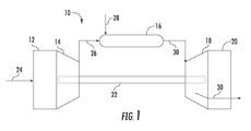
ここで図面を参照すると、図1は、典型的なガスタービン10の概略図を示している。ガスタービン10は、一般的に、吸気部12、吸気部12の下流に配置された圧縮機14、圧縮機14の下流に配置された燃焼部16、燃焼部16の下流に配置されたタービン18、およびタービン18の下流に配置された排気部20を含む。さらに、ガスタービン10は、圧縮機14をタービン18に結合させる1つ以上のシャフト22を含むことができる。
With reference to the drawings here, FIG. 1 shows a schematic diagram of a
動作時に、空気24が、吸気部12を通って圧縮機14へと流れ、圧縮機14において次第に圧縮され、したがって、圧縮空気26が燃焼部16へともたらされる。圧縮空気26の少なくとも一部は、燃焼部16において燃料28と混合されて燃やされ、燃焼ガス30を発生させる。燃焼ガス30は、燃焼部16からタービン18へと流れ、タービン18において燃焼ガス30からロータブレード(図示せず)へとエネルギ(運動および/または熱)が移され、シャフト22を回転させる。次いで、この機械的な回転エネルギを、圧縮機14を動作させ、さらには/あるいは電気を発生させるなど、種々の目的に使用することができる。次いで、タービン18を出る燃焼ガス30を、排気部20を介してガスタービン10から排出することができる。
During operation, the
図2は、本開示のさまざまな実施形態による燃焼部16の上流側の図を示している。図2に示されるように、燃焼部16は、外側ケーシングまたは圧縮機吐出ケーシング32によって少なくとも部分的に囲まれてよい。圧縮機吐出ケーシング32は、燃焼部16の種々の構成要素を少なくとも部分的に囲む高圧プレナム34を少なくとも部分的に定めることができる。高圧プレナム34は、圧縮機14(図1)に流体連通し、圧縮機14から圧縮空気26を受け取ることができる。種々の実施形態において、図2に示されるように、燃焼部16は、ガスタービンのシャフト22に一致してよい軸方向の中心線38を中心にして周状に配置されたいくつかの一体型燃焼器ノズル100を含む分割型環状燃焼システム36を含む。
FIG. 2 shows a view of the upstream side of the
図3は、本開示の少なくとも1つの実施形態による分割型環状燃焼システム36の一部分について、第1の側から見た部分分解斜視図を示している。図4は、本開示の少なくとも1つの実施形態による分割型環状燃焼システム36の一部分について、第2の側から見た部分分解斜視図を示している。図2、図3、および図4に共同で示されるように、分割型環状燃焼システム36は、複数の一体型燃焼器ノズル100を含む。本明細書でさらに説明されるように、各々の燃焼器ノズル100は、第1の側壁および第2の側壁を含む。特定の実施形態においては、下流のタービンノズル120の正圧側および負圧側のそれぞれとの側壁の一体化に基づいて、第1の側壁が正圧側側壁である一方で、第2の側壁が負圧側側壁である。本明細書においてなされる正圧側側壁および負圧側側壁への言及は、特定の実施形態を代表したものであり、そのような言及が、検討を容易にするためになされており、そのような言及が、とくに具体的な文脈によって指示されない限り、いかなる実施形態の範囲も限定しようとするものではないことを、理解すべきである。
FIG. 3 shows a partially exploded perspective view of a portion of the split
図3および図4に共同で示されるように、円周方向に隣接する燃焼器ノズル100の各ペアが、燃焼器ノズル100の間にそれぞれの主燃焼ゾーン102およびそれぞれの二次燃焼ゾーン104を定めることで、主燃焼ゾーン102および二次燃焼ゾーン104の環状アレイが形成される。主燃焼ゾーン102および二次燃焼ゾーン104は、隣接する主燃焼ゾーン102および二次燃焼ゾーン104のそれぞれから、燃料噴射パネル110によって円周方向において隔てられ、あるいは流体に関して分離されている。
As jointly shown in FIGS. 3 and 4, each pair of combustor nozzles adjacent in the circumferential direction has a
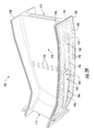
図3および図4に共同で示されるように、各々の燃焼器ノズル100は、内側ライナセグメント106と、外側ライナセグメント108と、内側ライナセグメント106と外側ライナセグメント108との間を延びる中空または半中空の燃料噴射パネル110とを含む。内側ライナセグメント106と外側ライナセグメント108との間に2つ以上の(例えば、2つ、3つ、または4つ以上の)燃料噴射パネル110を配置することにより、シールを必要とする隣接するライナセグメント間の接合部の数を、減らすことができると考えられる。本明細書における説明を容易にするために、それぞれの内側および外側ライナセグメント106、108の間に燃料噴射パネル110を1枚だけ有している一体型燃焼器ノズル100に言及するが、燃料噴射パネルに対するライナセグメントの2:1の比率は、必須ではない。図3および図4に示されるように、各々の燃料噴射パネル110は、前端部分または上流端部分112と、後端部分または下流端部分114と、第1の(正圧側)側壁116(図3)と、第2の(負圧側)側壁118(図4)とを含む。
As jointly shown in FIGS. 3 and 4, each
分割型環状燃焼システム36は、図3および図4においては燃焼器ノズル100から分解されて図示されている複数の環状に配置された燃料噴射モジュール300をさらに含む。各々の燃料噴射モジュール300は、燃料ノズル部分302(集合管燃料ノズルとして図示されている)と、それぞれの燃料噴射パネル110の前端部分112に設置されるように構成された複数の燃料噴射ランス304とを含む。本明細書における説明の目的で、燃料ノズル部分302は、「集合管燃料ノズル」または「集合管燃料ノズル部分」と呼ばれることもある。しかしながら、燃料ノズル部分302は、任意の種類の燃料ノズルまたはバーナ(スワール燃料ノズルまたはスウォズルなど)を含み、あるいは備えることができ、特許請求の範囲は、とくに述べられない限りは、集合管燃料ノズルに限定されるべきではない。
The split
各々の燃料噴射モジュール300は、円周方向において隣接する2つの燃料噴射パネル110の間を円周方向に少なくとも部分的に延びることができ、さらには/あるいはそれぞれの燃焼器ノズル100のそれぞれの内側ライナセグメント106および外側ライナセグメント108の間を半径方向に少なくとも部分的に延びることができる。軸方向に多段化された燃料噴射の動作の際に、集合管燃料ノズル部分302が、あらかじめ混合された燃料および空気の流れ(すなわち、第1の可燃性混合物)をそれぞれの主燃焼ゾーン102へともたらす一方で、燃料噴射ランス304は、詳しくは後述される複数の正圧側および/または負圧側予混合チャネルを介してそれぞれの二次燃焼ゾーン104へと(第2の可燃性混合物の一部としての)燃料をもたらす。
Each
少なくとも1つの実施形態において、図3および図4に示されるように、1つ以上の燃料噴射パネル110の下流端部分114は、燃焼生成物の流れをタービンブレードに向かって加速させるおおむね翼形の形状のタービンノズル120へと変化する。したがって、各々の燃料噴射パネル110の下流端部分114を、前縁を有さない翼形部と見なすことができる。一体型燃焼器ノズル100が燃焼部16内に取り付けられるときに、タービンノズル120を、タービン18のタービンロータブレード段のすぐ上流に位置させることができる。
In at least one embodiment, as shown in FIGS. 3 and 4, the
本明細書において使用されるとき、「一体型燃焼器ノズル」という用語は、燃料噴射パネル110、燃料噴射パネルの下流のタービンノズル120、燃料噴射パネル110の前端112から後端114(タービンノズル120によって具現化される)まで延びる内側ライナセグメント106、および燃料噴射パネル110の前端112から後端114(タービンノズル120によって具現化される)まで延びる外側ライナセグメント108を含む継ぎ目のない構造を指す。少なくとも1つの実施形態において、一体型燃焼器ノズル100のタービンノズル120は、第1段のタービンノズルとして機能し、タービンロータブレードの第1の段の上流に配置される。
As used herein, the term "integrated combustor nozzle" refers to the
上述したように、1つ以上の一体型燃焼器ノズル100は、内側ライナセグメント106、外側ライナセグメント108、燃料噴射パネル110、およびタービンノズル120を含む一体または単一の構造体または物体として形成される。一体型燃焼器ノズル100を、鋳造、付加製造(3D印刷など)、または他の製造技術によって、一体化された構成要素または継ぎ目のない構成要素として製造することができる。燃焼器ノズル100を単一または一体の構成要素として形成することにより、燃焼器ノズル100の種々の造作の間のシールの必要性を減らし、あるいは無くすことができ、部品の数およびコストを減らすことができ、組み立て工程を単純にし、あるいは無くすことができる。他の実施形態においては、燃焼器ノズル100を、溶接などによって製造することができ、あるいは異なる製造技術から形成することができ、その場合には、或る技術で製作された構成要素が、同じまたは別の技術によって製作された構成要素に接合される。
As mentioned above, the one or more
特定の実施形態において、各々の一体化型燃焼器ノズル100の少なくとも一部分またはすべてを、セラミックマトリックス複合材料(CMC)または他の複合材料から形成することができる。他の実施形態においては、各々の一体型燃焼器ノズル100の一部分またはすべて、より具体的にはタービンノズル120またはその後縁を、(遮熱コーティングで覆われた)酸化によく耐える材料から製作することができ、あるいは酸化によく耐える材料で覆うことができる。
In certain embodiments, at least a portion or all of each
別の実施形態(図示せず)においては、少なくとも1つの燃料噴射パネル110が、燃料噴射パネル110の長手方向(軸方向)の軸線に整列した後縁へと先細りであってよい。すなわち、燃料噴射パネル110は、タービンノズル120に一体化されなくてもよい。これらの実施形態においては、燃料噴射パネル110およびタービンノズル120の数が同じでないことが望ましい場合がある。先細りの燃料噴射パネル110(すなわち、一体のタービンノズル120を有さない燃料噴射パネル110)を、一体のタービンノズル120を有する燃料噴射パネル110(すなわち、一体型燃焼器ノズル100)と交互または何らかの他のパターンにて使用することができる。
In another embodiment (not shown), at least one
再び図3および図4を参照すると、いくつかの実施形態においては、軸方向のジョイントまたは分割線122が、円周方向において隣接する一体型燃焼器ノズル100の内側ライナセグメント106と外側ライナセグメント108との間に形成されてよい。分割線122を、隣接する一体型燃焼器ノズル100の各ペアの間に形成されるそれぞれの主燃焼ゾーン102および二次燃焼ゾーン104の円周方向における中央に沿って配置でき、あるいは何らかの他の位置に配置することができる。一実施形態においては、1つ以上のシール(スプライン型シールなど)を、各々のジョイント122に沿って配置でき、各々のジョイント122は、ライナセグメント106または108のそれぞれの隣接するエッジの一方または両方に凹状のシール受け領域(図示せず)を含むことができる。隣接する一体型燃焼器ノズル100の円周方向において隣接する各々のタービンノズル120の間に、別個のスプライン型シールを使用することができる。他の実施形態(図示せず)においては、ライナセグメント106,108が、複数の一体型燃焼器ノズル100にまたがって円周方向に延在でき、この場合、燃焼システム36について必要なシールの数が少なくて済み、燃焼ゾーン102,104のいくつかのサブセットが、周囲の分割線122およびシールを有することができる。
Referring again to FIGS. 3 and 4, in some embodiments, axial joints or dividing
図5が、本開示の少なくとも1つの実施形態による少なくとも部分的に組み立てられた典型的な一体化型燃焼器ノズル100の正圧側116の断面図を示している。特定の実施形態においては、図3、図4、および図5に共同で示されるように、タービンノズル120の部分または1つ以上の燃料噴射パネル110の下流端部分114の一部分を、対応するシールド124によって少なくとも部分的に覆い、あるいは包むことができる。図3および図4は、1つのシールド124が燃料噴射パネル110の対応するタービンノズル部分120から分離され、2つのさらなるシールド124が円周方向において隣接するタービンノズル120に取り付けられている状態の図を示している。シールド124を、一体型燃焼器ノズル100の高温の動作環境に適した任意の材料から形成することができる。例えば、1つ以上の実施形態においては、1つ以上のシールド124を、CMCまたは酸化によく耐える他の材料から形成することができる。いくつかの例では、シールド124を、遮熱コーティングで覆うことができる。
FIG. 5 shows a cross-sectional view of the
特定の実施形態においては、図3、図4、および図5に示されるように、内側ライナセグメント106のうちの燃料噴射パネル110の下流端部分114に近接する部分を、シールド124をタービンノズル120へと滑らせることができるように形成することができる。内側ライナセグメント106へと取り付けられる内側フックプレート228を、シールド124を所定の場所に固定するために使用することができる。
In certain embodiments, as shown in FIGS. 3, 4, and 5, the
種々の実施形態においては、図3に示されるように、各々の燃料噴射パネル110が、正圧側側壁116に沿って定められた半径方向に間隔を空けつつ位置する複数の正圧側噴射出口126を含むことができる。図4に示されるように、各々の燃料噴射パネル110は、負圧側側壁118に沿って定められた半径方向に間隔を空けつつ位置する複数の負圧側噴射出口128を含むことができる。それぞれの主燃焼ゾーン102の各々は、1対の円周方向において隣接する一体型燃焼器ノズル100の対応する正圧側噴射出口126および/または負圧側噴射出口128の上流に定められる。二次燃焼ゾーン104の各々は、1対の円周方向において隣接する一体型燃焼器ノズル100の対応する正圧側噴射出口126および/または負圧側噴射出口128の下流に定められる。
In various embodiments, as shown in FIG. 3, each
図3、図4、および図5に共同で示されるように、円周方向において隣接する2つの燃料噴射パネル110の正圧側噴射出口126および負圧側噴射出口128は、第2の燃料および空気混合物をそれぞれの主燃焼ゾーン102から由来する燃焼ガスの流れへと噴射するそれぞれの噴射面130、131を定める。特定の実施形態においては、正圧側噴射面130と負圧側噴射面131とを、燃料噴射パネル110の下流端部分114から同じ軸方向距離に定めることができ、すなわち軸方向において燃料噴射パネル110の下流端部分114からの同じ軸方向距離に位置させることができる。他の実施形態においては、正圧側噴射面130および負圧側噴射面131を、燃料噴射パネル110の下流端部分114からの異なる軸方向距離に定めることができ、すなわち軸方向において燃料噴射パネル110の下流端部分114からの異なる軸方向距離に位置させることができる。
As jointly shown in FIGS. 3, 4, and 5, the positive pressure
図3および図5は、複数の正圧側噴射出口126を、一体型燃焼器ノズル100の軸方向の中心線に対する共通の半径方向の平面または噴射面130に位置し、すなわち燃料噴射パネル110の下流端部分114から共通の軸方向距離に位置するものとして図示しているが、特定の実施形態においては、正圧側噴射出口126のうちの1つ以上を、半径方向において隣接する正圧側噴射出口126と比べて軸方向にずらすことで、特定の正圧側噴射出口126について下流端部分114までの正圧側噴射出口126の軸方向距離をオフセットしてもよい。同様に、図4は、複数の負圧側噴射出口128を、共通の半径方向の平面または噴射面131に位置し、すなわち燃料噴射パネル110の下流端部分114から共通の軸方向距離に位置するものとして図示しているが、特定の実施形態においては、負圧側噴射出口128のうちの1つ以上を、半径方向において隣接する負圧側噴射出口128と比べて軸方向にずらすことで、特定の負圧側噴射出口128について下流端部分114までの負圧側噴射出口128の軸方向距離をオフセットしてもよい。
3 and 5 show the plurality of positive pressure
さらに、噴射出口126,128は、均一なサイズ(すなわち、断面積)を有するものとして図示されているが、場合によっては、燃料噴射パネル110の異なる領域において異なるサイズの噴射出口126,128を使用することが望ましい場合がある。例えば、より大きな直径を有する噴射出口126,128を、燃料噴射パネル110の半径方向中央部に使用できる一方で、より小さな直径を有する噴射出口126,128を、内側ライナセグメント106および外側ライナセグメント108に近い領域に使用することができる。同様に、所与の側壁116または118の噴射出口126または128に、対向する側壁118または116の噴射出口128または126とは異なるサイズを持たせることが、望ましい場合がある。
Further, although the
上述したように、少なくとも1つの実施形態においては、二次の燃料−空気の導入を、燃料噴射パネル110の片側(例えば、正圧側側壁116または負圧側側壁118)から生じさせることが、望ましい場合がある。したがって、各々の燃料噴射パネル110は、共通の側壁(116または118)上に出口を有するただ1組の予混合チャネルのみを備えることができる。さらに、各々の燃料噴射パネル110は、一方の側壁上に予混合チャネルの2つ(または、3つ以上)のサブセットを備えることができ、これらのサブセットに、燃料噴射ランス304のそれぞれのサブセットによって別々に燃料を供給することができ、ランス304の各々のサブセットへの燃料供給を、独立に開始させ、減少させ、あるいは停止することができる。他の実施形態においては、各々の燃料噴射パネル110が、両方の側壁(116および118)上に出口を有する予混合チャネルの2つ(または、3つ以上)のサブセットを備えることができ、これらのサブセットに、(図13に示されるとおりの)燃料噴射ランス304のそれぞれのサブセットによって別々に燃料を供給することができ、ランス304の各々のサブセットへの燃料供給を、独立に開始させ、減少させ、あるいは停止することができる。
As mentioned above, in at least one embodiment, it is desirable to generate the secondary fuel-air from one side of the fuel injection panel 110 (eg, positive pressure
図6、図7、および図8が、図5に示した燃焼器ノズル100について、切断線6−6、切断線7−7、および切断線8−8のそれぞれに沿って得た断面図を示している。
6, FIG. 7, and FIG. 8 show cross-sectional views of the
図6および図7に共同で示されるように、各々の燃料噴射パネル110は、燃料噴射パネル110の側面に出口を有する複数の予混合チャネルを含む。一例において、正圧側予混合チャネル132(図6)が、正圧側116に出口126を有するチャネルである一方で、負圧側予混合チャネル134(図7)は、負圧側118に出口128を有するチャネルである。各々の正圧側予混合チャネル132は、それぞれの正圧側噴射出口126に流体連通している。各々の負圧側予混合チャネル134は、それぞれの負圧側噴射出口128に流体連通している。少なくとも1つの実施形態においては、図6に示されるように、正圧側予混合チャネル132が、正圧側側壁116と負圧側側壁118との間の燃料噴射パネル110の内部に定められる。少なくとも1つの実施形態においては、図7に示されるように、負圧側予混合チャネル134が、正圧側側壁116と負圧側側壁118との間の燃料噴射パネル110の内部に定められる。
As jointly shown in FIGS. 6 and 7, each
上述したように、燃料噴射パネル110は、片側(正圧側側壁116または負圧側側壁118のいずれか)に沿って配置された出口を終端とする予混合チャネル(132または134)を有することができると考えられる。したがって、本明細書においては、正圧側側壁116および負圧側側壁118の両方に出口126,128を有する実施形態を参照しているが、特許請求の範囲に記載されていない限り、燃料−空気混合物をもたらすための出口126,128を正圧側側壁116および負圧側側壁118の両方が有する必要はないことを、理解すべきである。
As mentioned above, the
特定の実施形態においては、図6および図7に示されるように、燃料噴射パネル110の正圧側側壁116および負圧側側壁118のいずれかまたは両方の肉厚Tを、燃料噴射パネル110の軸方向(または、長手方向)の長さおよび/または半径方向のスパンに沿って変化させることができる。例えば、燃料噴射パネル110の正圧側側壁116および負圧側側壁118のいずれかまたは両方の肉厚Tを、上流端部分112と下流端部分114との間、および/または内側ライナセグメント106と外側ライナセグメント108(図5)との間で変化させることができる。
In a particular embodiment, as shown in FIGS. 6 and 7, the wall thickness T of either or both of the positive pressure
特定の実施形態においては、図6に示されるように、全体としての噴射パネルの厚さPTを、燃料噴射パネル110の軸方向(または、長手方向)の長さおよび/または半径方向のスパンに沿って変化させることができる。例えば、正圧側側壁116および/または負圧側側壁118が、2つの円周方向において隣接する一体型燃焼器ノズル100の間を流れる燃焼ガスの流れへと向かい、さらには/あるいはそのような流れの中へと外側に膨らむ凹部を含むことができる。全体としての噴射パネルの厚さPTにおける膨らみまたは変動は、それぞれの正圧側側壁116または負圧側側壁118の半径方向のスパンおよび/または軸方向の長さに沿った任意の地点で生じ得る。パネルの厚さPTまたは膨らみの位置を、局所領域を肉厚Tの変更を必要とすることなく特定の目標速度および滞留時間プロファイルを達成するように仕立てるために、正圧側側壁116または負圧側側壁118の軸方向の長さおよび/または半径方向のスパンに沿って変化させることができる。膨らみの領域を、所与の燃料噴射パネル110の正圧側側壁116および負圧側側壁118に両方において対称にする必要はない。
In certain embodiments, as shown in FIG. 6, the overall injection panel thickness PT is extended to the axial (or longitudinal) length and / or radial span of the
特定の実施形態においては、図6に示されるように、正圧側予混合チャネル132のうちの1つ以上が、燃料噴射パネル110の長手軸に沿って延びるおおむね一直線または直線状の部分136と、それぞれの正圧側噴射出口126のすぐ上流に定められるおおむね湾曲した部分138とを有することができる。特定の実施形態においては、図7に示されるように、負圧側予混合チャネル134のうちの1つ以上が、燃料噴射パネル110の長手軸に沿って延びるおおむね一直線の部分140と、対応する負圧側噴射出口128のすぐ上流に定められる湾曲した部分142とを有することができる。湾曲した部分138,142は、内側半径(燃料噴射パネル110の上流端112に向かう)および外側半径(燃料噴射パネル110の下流端114に向かう)を含むことができる。少なくとも1つの実施形態においては、図8に示されるように、正圧側予混合チャネル132が、半径方向に間隔を空けつつ位置することができ、あるいは対応する負圧側予混合チャネル134によって隔てられてよい。
In certain embodiments, as shown in FIG. 6, one or more of the positive pressure side premixed
特定の実施形態においては、図6および図7に示されるように、正圧側予混合チャネル132および/または負圧側予混合チャネル134は、燃料噴射パネル110の正圧側側壁116と負圧側側壁118との間を横切り、あるいは屈曲して延びることができる。一実施形態において、正圧側予混合チャネル132および/または負圧側予混合チャネル134は、燃料噴射パネル110の一直線または一定の軸方向(または、長手方向)平面に沿うよりもむしろ、正圧側側壁116と負圧側側壁118との間を半径方向内側および/または外側に横切ることができる。正圧側予混合チャネル132および/または負圧側予混合チャネル134を、燃料噴射パネル110内でさまざまな角度に向けることができる。特定の実施形態においては、1つ以上の正圧側予混合チャネル132および/または負圧側予混合チャネル134が、さまざまなサイズおよび/または形状にて形成されてよい。特定の実施形態においては、1つ以上の予混合チャネル132,134が、曲がり、ねじれ、よじれ、螺旋状部分、タービュレータ、などの混合促進用の造作を含むことができる。
In certain embodiments, as shown in FIGS. 6 and 7, the positive pressure
図6、図7、および図8に共同で示されるように、それぞれの燃料噴射モジュール300からの燃料噴射ランス304が、燃料噴射パネル110内に定められ、とくには燃料噴射パネル110の上流端部分112の付近において正圧側側壁116と負圧側側壁118(図6および図7)との間に定められた予混合空気プレナム144を通って延びる。各々の燃料噴射ランス304の下流端部分306が、それぞれの燃料噴射パネル110のそれぞれの正圧側予混合チャネル132またはそれぞれの負圧側予混合チャネル134の中へと少なくとも部分的に延び、これらに流体連通している。やはり、必ずしも両方の予混合チャネル132,134が存在する必要はない。むしろ、1組の予混合チャネル132または134だけを使用してもよい。
As jointly shown in FIGS. 6, 7, and 8, fuel injection lances 304 from the respective
図9が、本開示の少なくとも1つの実施形態による複数の一体型燃焼器ノズル100のうちの典型的な一体型燃焼器ノズル100について、予混合空気プレナム144の一部分を切断した断面の下流方向の斜視図である。図10は、本開示の少なくとも1つの実施形態による図9に示した燃料噴射パネル110の一部分の拡大図を示している。
FIG. 9 shows the downstream direction of the cross section of the premixed
少なくとも1つの実施形態においては、図9および図10に共同で示されるように、各々の燃料噴射パネル110が、燃料噴射ランス304を予混合チャネル132,134へと導くための半径方向に間隔を空けつつ位置する複数の環状のカラーまたは座146を含む。各々のカラー146は、中央開口部151を定めており、複数のストラット148によって支持されている。各々のカラー146は、対応する燃料噴射ランス304の中央開口部151への挿入または整列を助けるために、中央開口部151に外接するテーパ部または発散部150を含むことができる。ストラット148を、それぞれのカラー146の周囲に対応する予混合チャネル132または134への流路152を定めるように、それぞれのカラー146の周りに間隔を空けつつ配置することができる。流路152は、予混合空気プレナム144と正圧側および負圧側予混合チャネル132,134との間の流体連通をもたらす。図6、図7、および図8に示されるように、カラー146を、燃料噴射ランス304の少なくとも一部分(下流端部分306など)を受け入れ、かつ/または支持するようなサイズとすることができる。
In at least one embodiment, as jointly shown in FIGS. 9 and 10, each
図11が、少なくとも1つの実施形態による典型的な燃料噴射ランス304が挿入された典型的な燃料噴射パネル110の一部分の上方からの(見下ろしの)断面図を示している。特定の実施形態においては、図11に示されるように、1つ以上の燃料噴射ランス304の下流端部分306が、送出先端部308を含む。送出先端部308は、(上述したとおりの)それぞれの燃料噴射パネル110のそれぞれのカラー146を通っての設置を容易にするために、円錐形、収束形、またはテーパ状であってよく、それぞれの正圧側予混合チャネル132またはそれぞれの負圧側予混合チャネル134へと少なくとも部分的に延びることができる。送出先端部308は、インジェクタ燃料プレナム336(後述)と流体連通する1つ以上の噴射ポート310を含むことができる。
FIG. 11 shows a cross-sectional view (overlooking) from above a portion of a typical
特定の実施形態においては、図11に示されるように、1つ以上の燃料噴射ランス304が、蛇腹部分またはカバー312を含む。蛇腹部分312は、分割型環状燃焼システム36の動作中の燃料噴射パネル110と噴射ランス304との間のおおむね軸方向の相対的な熱による伸びまたは移動を許容することができる。特定の実施形態においては、図11に示されるように、燃料噴射パネル110が、燃料噴射パネル110の上流端部分112に近接して配置され、あるいは燃料噴射パネル110の上流端部分112に結合した複数の浮動カラー154を含むことができる。浮動カラー154は、一体型燃焼器ノズル100(とくには、燃料噴射パネル110)と燃料噴射モジュール300との間の半径方向および/または軸方向の移動を許容することができる。
In certain embodiments, as shown in FIG. 11, one or more fuel injection lances 304 include a bellows portion or
図8〜図11に示されるように、予混合チャネル132,134は、燃料噴射パネル110の正圧側側壁116と負圧側側壁118との間に配置された共通の半径方向の平面内に配置されている。あるいは、図12に示されるように、正圧側予混合チャネル132および/または負圧側予混合チャネル134を、出口を燃料噴射パネル110の両側面に位置させ、あるいは出口を燃料噴射パネル110の同じ側面に位置させつつ、燃料噴射パネル110の負圧側側壁118および/または正圧側側壁116と一体に形成してもよい。この実施形態においては、燃料噴射ランス304を、燃料噴射ランス304が対応する予混合チャネル132、134の入口に整列するように、正圧側燃料噴射ランスからなる第1のサブセットおよび負圧側燃料噴射ランスからなる第2のサブセットへと円周方向に分けることができる。燃料噴射ランス304の第1のサブセットおよび燃料噴射ランス304の第2のサブセットに、1つ以上のインジェクタ燃料プレナム336によって燃料をもたらすことができる。
As shown in FIGS. 8 to 11, the premixed
図13が、一実施形態による典型的な一体型燃焼器ノズル100の一部分へと挿入された典型的な燃料噴射モジュール300の下流側への斜視図を示している。図14が、図13に示したとおりの燃料噴射モジュール300の上流側への斜視図を示している。種々の実施形態において、図13および図14に共同で示されるように、燃料噴射モジュール300は、ハウジング本体314を有する集合管燃料ノズル部分302を含む。ハウジング本体314は、前方(または、上流側)プレートまたは面316と、後方(または、下流側)プレートまたは面318と、前方プレート316から後方プレート318まで軸方向に延びる外周壁320と、外周壁320の内側を前方プレート316および後方プレート318を通って軸方向に延びる複数の管322とを含むことができる。特定の実施形態においては、(浮動カラーシールなどの)シール324が、ハウジング本体314の外周壁320の少なくとも一部分を取り囲む。シール324は、円周方向において隣接する燃料噴射モジュール300の外壁などのシール面と係合して、それらの間の流体の流れを防止または低減することができる。
FIG. 13 shows a downstream perspective view of a typical
各々の管322は、前方プレート316またはその上流に定められた入口326(図13)と、後方プレート318またはその下流に定められた出口328(図14)と、それぞれの入口326および出口328の間を延びる予混合通路330(図14に隠れ線で示されている)とを含む。図14に隠れ線で示されているように、燃料ノズルプレナム332が、燃料噴射モジュール300のハウジング本体314の内部に定められる。複数の管322の各々の管322は、燃料ノズルプレナム332を通って延びている。管322の少なくともいくつかは、燃料ノズルプレナム332内に配置された少なくとも1つの燃料ポート334を含み、あるいは燃料ノズルプレナム332内に配置された少なくとも1つの燃料ポート334を定める。各々の燃料ポート334は、燃料ノズルプレナム332からそれぞれの予混合通路330への流体連通を可能にする。特定の実施形態においては、燃料ノズルプレナム332を、ハウジング本体314内に定められた2つ以上の燃料ノズルプレナム332へと細分化し、あるいは仕切ることができる。
Each
動作時に、気体燃料(または、いくつかの実施形態においては、気体混合物へと改質された液体燃料)が、燃料ノズルプレナム332から燃料ポート334を介して各々の管322のそれぞれの予混合通路330へと流れ、各々の管322のそれぞれの入口326に進入する空気と混ざり合う。燃料ポート334を、例えば、2つの隣接する一体型燃焼器ノズル100の間で燃焼力学を処置または調節し、あるいは分割型環状燃焼システム36とタービン18との間でコヒーレントな軸方向モードを緩和するためにマルチタウ(multi−tau)配置が望まれる場合に、単一の軸方向平面または2つ以上の軸方向平面においてそれぞれの管322に沿って位置させることができる。
During operation, the gaseous fuel (or, in some embodiments, the liquid fuel reformed into a gaseous mixture), from the
図13に示した実施形態においては、複数の燃料噴射ランス304の各々の燃料噴射ランス304が、燃料噴射モジュール300のハウジング本体314の外周壁320の半径方向壁部分に沿って、隣接する燃料噴射ランス304から半径方向に間隔を空けて配置されている。図13に隠れ線で示されているように、インジェクタ燃料プレナムまたは燃料回路336は、燃料噴射モジュール300のハウジング本体314の内部に定められる。
In the embodiment shown in FIG. 13, each
特定の実施形態において、燃料噴射ランス304は、インジェクタ燃料プレナム336に流体連通する。特定の実施形態において、インジェクタ燃料プレナム336は、2つ以上のインジェクタ燃料プレナム336に細分化されてもよい。例えば、特定の実施形態においては、インジェクタ燃料プレナム336を、複数の燃料噴射ランス304のうちの第1のサブセット340に燃料を供給することができる第1のインジェクタ燃料プレナム338と、複数の燃料噴射ランス304のうちの第2のサブセット344に燃料を供給することができる第2のインジェクタ燃料プレナム342とに細分化することができる。図示のように、燃料噴射ランス304の第1のサブセット340は、半径方向内側のサブセットであってよく、燃料噴射ランス304の第2のサブセット344は、半径方向外側のサブセットであってよい。
In certain embodiments, the
他の実施形態においては、複数の燃料噴射ランス304のうちの1つおきの燃料噴射ランス304に、第1のインジェクタ燃料プレナムによって燃料を供給することができる一方で、残りのランス304には、別の燃料インジェクタプレナムによって燃料が供給される。このような構成においては、一方の側壁に沿って出口を有する予混合チャネル(例えば、132)への燃料の供給を、反対側の側壁の予混合チャネル(例えば、134)への燃料の供給から独立して行うことが可能である。
In another embodiment, every other
特定の実施形態においては、燃料噴射ランス304を、燃料噴射ランスの半径方向外側のサブセット304(a)、燃料噴射ランスの中間または中央のサブセット304(b)、および燃料噴射ランスの半径方向内側のサブセット304(c)へと細分化することができる。この構成において、燃料噴射ランスの半径方向外側のサブセットおよび半径方向の内側サブセット304(a)、304(c)が、或る1つの燃料インジェクタプレナムから燃料を受け取ることができる一方で、燃料噴射ランスの中間のサブセット304(b)、もう1つの(別個の)燃料インジェクタプレナムから燃料を受け取ることができる。複数の燃料噴射ランス304を、燃料噴射ランス304の燃料が別個独立に供給され、あるいは共通に供給される複数のサブセットへと細分化することができるが、本開示は、特許請求の範囲にとくに記載されない限り、燃焼噴射ランスの2つまたは3つのサブセットに限定されない。
In certain embodiments, the
燃料を、分割型環状燃焼システム36の前端部分から燃料噴射モジュール300内の種々のプレナムへと供給することができる。例えば、燃料を、圧縮機吐出ケーシング32に結合した端部カバー(図示せず)を介し、さらには/あるいは圧縮機吐出ケーシング32の前端部分に配置された1つ以上の管または導管を介して、種々の燃料噴射モジュール300へと供給することができる。
Fuel can be supplied from the front end portion of the split
あるいは、燃料を、半径方向外側の燃料マニホールドまたは燃料供給アセンブリ(図示せず)から燃料噴射モジュール300へと外側ライナセグメント108を通って半径方向に供給することができる。さらに別の構成(図示せず)においては、燃料を、集合管燃料ノズル302または燃料噴射ランス304を介して導入される前に燃料噴射パネル110を冷却するように、燃料噴射パネル110の後端114へと供給し、正圧側側壁116および/または負圧側側壁118を通って導くことができる。
Alternatively, fuel can be delivered radially from the radially outer fuel manifold or fuel supply assembly (not shown) to the
別の構成(図示せず)においては、燃料を、燃料噴射パネル110の後端114へと供給し、燃料噴射パネル110の後端から始まって正圧側側壁116および負圧側側壁118に出口126、128をそれぞれ有している予混合チャネル132,134へと導くことができる。この構成においては、燃料噴射ランス304の必要性がなくなり、集合管燃料ノズル302への燃料を、(本明細書に記載の燃料供給導管などの燃料供給導管を介して)半径方向または軸方向に供給することができる。
In another configuration (not shown), fuel is supplied to the
図13に示されるように、種々の実施形態においては、燃料ノズルプレナム332ならびに/あるいはインジェクタ燃料プレナム336またはインジェクタ燃料プレナム338,342に燃料を供給するために、1つ以上の導管346を使用することができる。例えば、一実施形態において、導管346は、チューブインチューブ(tube−in−tube)構成を形成する内側管350を同心円状に取り囲む外側管348を含むことができる。この実施形態においては、外側燃料回路352が、内側管350と外側管348との間に半径方向に定められ、内側燃料回路354が、内側管350の内側に形成され、したがって燃料ノズルプレナム332および/またはインジェクタ燃料プレナム336,338,342への同心な燃料流路が定められる。例えば、外側燃料回路352が、インジェクタプレナム336,338,342のうちの1つ以上へと燃料を供給できる一方で、内側燃料回路354が、燃料ノズルプレナム332へと燃料を供給でき、あるいは逆もまた然りである。別の実施形態(図示せず)においては、燃料ノズルプレナム332およびインジェクタ燃料プレナム336に燃料をもたらすために、別個の管348,350を使用してもよい。
As shown in FIG. 13, in various embodiments, one or
図15が、別の実施形態による燃料噴射モジュール300の上流側への斜視図を示している。図16が、別の実施形態による別の燃料噴射モジュール300の上流側への斜視図を示している。図17は、円周方向に隣接する一体型燃焼器ノズル100に組み込まれた複数の(図15に示したとおりの)燃料噴射モジュール300の下流側への斜視図を示している。
FIG. 15 shows a perspective view of the
図15、図16、および図17に共同で示される実施形態においては、集合管燃料ノズル部分302の複数の管322が、管の第1のサブセット356および管の第2のサブセット358に細分化される。ハウジング本体314は、共通の前方プレート316と、第1の後方プレート360と、第2の後方プレート362と、管の各々のサブセット356,358の周囲に延在して、1つ以上のそれぞれの燃料ノズルプレナム(図示せず)を定める外周壁320とを含む。本明細書において使用されるとき、用語「燃料ノズルプレナム」および「集合管燃料プレナム」は、燃料噴射モジュール300の燃料ノズル部分302(場合によっては、集合管燃料ノズル)へと燃料を供給する燃料プレナムを指して入れ換え可能に使用され得る。
In the embodiment jointly shown in FIGS. 15, 16, and 17, the plurality of
管の第1のサブセット356は、前方プレート316、ハウジング本体314内に定められた第1の燃料ノズルプレナム、および第1の後方プレート360を通って延びる。管の第2のサブセット358は、前方プレート316、ハウジング本体314内に定められた第2の燃料ノズルプレナム、および第2の後方プレート362を通って延びる。図15に示されるように、複数の燃料噴射ランス304が、円周方向において管の第1のサブセット356と管の第2のサブセット358との間および/または第1の後方プレート360と第2の後方プレート362との間に配置される。
A first subset of
図16は、燃料噴射パネル110内のインジェクタ燃料プレナムへと燃料が半径方向にもたらされる実施形態において使用することができる別の燃料噴射モジュール300を示している。この実施形態においては、燃料噴射ランス304を燃料噴射モジュール300から省略して、管のそれぞれのサブセット356,358の間に円周方向のすき間を残すことができる。
FIG. 16 shows another
特定の実施形態においては、図14、図15、および図16に示されるように、燃料噴射モジュール300のうちの1つ以上が、燃料噴射モジュール300の集合管燃料ノズル部分302から出る燃料および空気混合物に点火するためのイグナイタ364を含むことができる。特定の実施形態においては、図15および図16に示されるように、シール366(フラ型またはばね式シールなど)を、1つ以上の燃料噴射モジュール300のハウジング本体314の側周壁368に沿って配置することができる。シール366は、隣接する燃料噴射モジュール300の隣接する側周壁と係合して、両者の間の流体の流れを防止または低減することができる。
In certain embodiments, as shown in FIGS. 14, 15, and 16, one or more of the
図15、図16、および図17は、各々の燃料噴射モジュール300に組み合わせられた1対の燃料導管382,392を示している。一実施形態(図15および図17)においては、燃料導管382,392を、上述したように、チューブインチューブ構成として製作することができる。この場合、第1の燃料導管382が、集合管の第1のサブセット356および燃料噴射ランス304の第1のサブセット(個別の参照番号は標記されていない)へと燃料を供給することができる一方で、他方の燃料導管392は、集合管の第2のサブセット358および燃料噴射ランス304の第2のサブセットへと燃料を供給することができる。
15, 16, and 17 show a pair of fuel conduits 382,392 combined with each
別の実施形態(図16)においては、燃料導管382が、集合管の第1のサブセット356に燃料を供給でき、第2の導管392が、集合管の第2のサブセット358に燃料を供給することができる。さらに別の変種においては、集合管の第1のサブセット356および集合管の第2のサブセット358に、(第1の燃料導管382による供給を受ける)共通の第1の燃料ノズルプレナム372および(第2の燃料導管392による供給を受ける)共通の第2の燃料ノズルプレナムによって供給を行うことで、管の各々のサブセット356,358を、集合管の半径方向内側および半径方向外側のグループにさらに分割することができる。すなわち、第1の集合サブセット356の半径方向内側の管および第2の集合サブセット358の半径方向内側の管に、第1の導管382によって燃料をもたらすことができる一方で、サブセット356,358の半径方向外側の管に、第2の導管392によって燃料をもたらすことができる。したがって、単一の燃料噴射モジュール300の共通のハウジング内に、別個独立に燃料を供給することができる半径方向内側および半径方向外側の集合管サブセットを作り出すことが可能である。
In another embodiment (FIG. 16), the
図17は、3つのそれぞれの燃焼器ノズル100に組み合わせられた図15の3つの典型的な燃料噴射モジュール300のセットを示している。図示されているように、集合管の第1のサブセット356は、燃料噴射パネル110の負圧側側壁(118)の円周方向外側に位置する。燃焼器ノズル100は、第1および第2の集合管燃料ノズルのサブセット356,358の間に位置する。第2の集合管燃料ノズルのサブセット358は、同じ燃料噴射パネル110の正圧側(116)の円周方向外側に位置する。したがって、各々の主燃焼ゾーン102は、第1の燃料噴射モジュール300の第2の集合管燃料ノズルのサブセット358および第2の(隣接する)燃料噴射モジュール300の第1の集合管燃料ノズル356からの燃料および空気混合物を燃焼させる。同様に、予混合チャネル132,134が燃料噴射パネル110の側壁の各々に配置されている実施形態においては、各々の二次燃焼ゾーン104が、第1の燃料噴射パネル110の負圧側予混合チャネル134および第2の(隣接する)燃料噴射パネル110の正圧側予混合チャネル132からの燃料および空気混合物を燃焼させる。
FIG. 17 shows a set of three typical
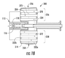
図18が、少なくとも1つの実施形態による燃料噴射パネル110の一部分および(図15および図17に示した)燃料噴射モジュール300を含む一体型燃焼器ノズル100の一部分の断面上面図を示している。図19が、少なくとも1つの実施形態による典型的な一体型燃焼器ノズル100に挿入された(図15に示した)燃料噴射モジュール300の実施形態について、正圧側側壁116を切除した断面側面図を示している。
FIG. 18 shows a cross-sectional top view of a portion of the
図18に示されるように、複数の管322のうちの管の第1のサブセット356は、それぞれの燃料噴射パネル110の負圧側側壁118の一部分に沿って延び、複数の管322のうちの管の第2のサブセット358は、同じ燃料噴射パネル110の正圧側側壁116に沿って延びている。このように、図17に示されるように、2つの円周方向に隣接する一体型燃焼器ノズル100に取り付けられた2つの円周方向に隣接する燃料噴射モジュール300が、分割型環状燃焼システム36の各々の主燃焼ゾーン102のための管322の全バンクを形成するために必要である。
As shown in FIG. 18, the
特定の実施形態において、図18および図19に示されるように、集合管燃料プレナム332は、2つ以上の集合管燃料プレナムに細分化されてもよい。例えば、一実施形態においては、集合管燃料プレナム332を、壁371あるいは燃料噴射モジュール300内に画定または配置された他の障害物によって、第1の集合管燃料プレナム370および第2の集合管燃料プレナム372へと細分化し、あるいは仕切ることができる。この構成においては、図18に示されるように、第1の集合管燃料プレナム370が、管の第1のサブセット356へと燃料を供給できる一方で、第2の集合管燃料プレナム372が、管の第2のサブセット358へと燃料を供給することができる。この構成においては、管の第1のサブセット356および管の第2のサブセット358に、互いに独立に燃料を供給することができ、あるいは管の第1のサブセット356および管の第2のサブセット358を、互いに独立に動作させることができる。
In a particular embodiment, as shown in FIGS. 18 and 19, the collecting
特定の実施形態においては、図18に示されるように、集合管燃料プレナム332を、ハウジング本体314内に配置された1つ以上のプレートまたは壁373によって管の一方または両方のサブセット356,358を横切って軸方向に細分化することにより、前方の集合管燃料プレナム332(a)および後方の集合管燃料プレナム332(b)を形成することができる。燃料ポート334のうちの1つ以上を、前方の集合管燃料プレナム332(a)に流体連通させ、燃料ポート334のうちの1つ以上を、後方の集合管燃料プレナム332(b)に流体連通させることにより、燃焼力学を処置または調節するためのマルチタウの柔軟性をもたらすことができる。
In certain embodiments, as shown in FIG. 18, the collecting
特定の実施形態においては、図19に示されるように、インジェクタ燃料プレナム336を、第1のインジェクタ燃料プレナム374および第2のインジェクタ燃料プレナム376に細分化または分割することができる。この実施形態においては、複数の燃料噴射ランス304を、燃料噴射ランス304の第1の(または、半径方向内側の)サブセット378および燃料噴射ランス304の第2の(または、半径方向外側の)サブセット380に細分化することができる。燃料噴射ランス304の第1のサブセット378が、第1のインジェクタ燃料プレナム374に流体連通でき、燃料噴射ランス304の第2のサブセット380が、第2のインジェクタ燃料プレナム376に流体連通することができる。
In certain embodiments, the
燃料噴射ランス304の第1の(または、半径方向内側の)サブセット378が、正圧側側壁および/または負圧側側壁の予混合チャネル132,134の半径方向内側の組に燃料を供給できる一方で、燃料噴射ランス304の第2の(または、半径方向外側の)サブセット380が、正圧側側壁および/または負圧側側壁の予混合チャネル132,134の半径方向外側の組に燃料を供給することができる。この構成は、運転モード(例えば、全負荷、部分負荷、またはターンダウン)または所望の排出性能に応じて、燃料噴射ランス304の第1のサブセットおよび燃料噴射ランス304の第2のサブセットを別個独立または一緒に動作させることができる点で、動作の柔軟性を高めることができる。
While the first (or radial inner)
図19は、内側燃料回路388と外側燃料回路390とを定めるチューブインチューブ構成を形成するように内側管386を同心円状に取り囲む外側管384を含んでいる第1の導管382をさらに示している。内側燃料回路388を、第1の集合管燃料プレナム370に燃料を供給するために使用することができ、外側燃料回路390を、第1のインジェクタ燃料プレナム374に燃料を供給するために使用することができる(あるいは、逆も可能)。チューブインチューブ構成を形成するように内側管396を同心円状に取り囲む外側管394を含んでいる第2の導管392が、内側燃料回路398および外側燃料回路400を定めている。内側燃料回路398を、第2の集合管燃料プレナム372に燃料を供給するために使用することができ、外側燃料回路400を、第2のインジェクタ燃料プレナム376に燃料を供給するために使用することができる。
FIG. 19 further shows a
好都合なことに、図15および図17〜図19に示した実施形態においては、燃料ノズル部分302および燃料噴射ランス304の両方への燃料が、共通の燃料導管(例えば、チューブインチューブ導管)によってもたらされるため、複雑さが低減され、部品数が最小限に抑えられる。本明細書においてはチューブインチューブ構成が例示されているが、代わりに、燃料ノズル部分302へと燃料を供給する少なくとも1つの燃料導管と、燃料噴射ランス304へと燃料を供給する少なくとも1つの他の燃料導管とを含む別々の燃料導管を使用してもよいことを、理解すべきである。
Conveniently, in the embodiments shown in FIGS. 15 and 17-19, the fuel to both the
図20は、少なくとも1つの実施形態による円周方向に隣接する1対の一体型燃焼器ノズル100と半径方向に取り付けられた1対の燃料噴射モジュール300とを含む分割型環状燃焼システム36の一部分の下流側への斜視図を示している。一実施形態においては、図20に示されるように、2つの燃料噴射モジュール300を半径方向に積み重ねることにより、半径方向内側および半径方向外側の燃料噴射モジュールセット402を形成することができる。燃料噴射モジュールセット402の各々の燃料噴射モジュール300に、すでに述べたように複数の燃料回路を有する導管404,406によって個別に燃料を供給することで、積み重ねられた燃料噴射モジュールセット402は、少なくとも4つの独立した燃料回路を有する。このようにして、それぞれの集合管燃料プレナムおよびインジェクタ燃料プレナムについて、すでに述べたように独立に燃料をもたらし、あるいは独立に動作させることができる。
FIG. 20 is a portion of a split
特定の実施形態においては、図20に示されるように、燃料噴射パネル110のうちの少なくとも1つが、それぞれの燃料噴射パネル110の正圧側側壁(図19では隠れている)および負圧側側壁118のそれぞれの開口部を通って延びる少なくとも1つのクロスファイヤ管156を定めることができる。クロスファイヤ管156は、円周方向に隣接する一体型燃焼器ノズル100の間の円周方向に隣接する主燃焼ゾーン102のクロスファイヤおよび点火を可能にする。
In certain embodiments, as shown in FIG. 20, at least one of the
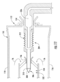
一実施形態においては、図21に示されるように、クロスファイヤ管156が、間に空気容積が定められる二重壁の円筒形構造によって定められる。第1の主燃焼ゾーン102で点火された燃焼ガス30は、クロスファイヤ管156の内壁を通って隣接する主燃焼ゾーン102へと流入し、隣接する主燃焼ゾーン102において燃料および空気混合物の点火を生じさせることができる。燃焼ガスがクロスファイヤ管156内に停滞することがないように、パージ空気孔158が内壁に設けられる。パージ空気孔158に加えて、クロスファイヤ管156の外壁に、燃料噴射パネル110内の少なくとも1つの空気空洞160,170または圧縮空気の何らかの他の供給源に流体連通することができる空気供給孔157を設けることができる。パージ空気孔158は、空気供給孔157を介して空気を受け取る空気容積に流体連通している。外壁のより小さい空気供給孔157と内壁のより大きいパージ空気孔158との組み合わせは、クロスファイヤ管156を、分割型環状燃焼システム36における潜在的な燃焼力学を軽減するための共振器に変換する。
In one embodiment, as shown in FIG. 21, the
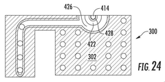
特定の実施形態においては、燃料噴射モジュール300のうちの1つ以上を、気体燃料に加えて液体燃料を燃焼させるように構成することができる。図22が、本開示の少なくとも1つの実施形態による気体燃料および液体燃料の両方で動作するように構成された典型的な燃料噴射モジュールの下流側への斜視図を示している。図23が、本開示の一実施形態による端部カバー40に結合した図22に示した典型的な燃料噴射モジュール300について、切断線23−23に沿って得た断面側面図を示している。図24が、本開示の一実施形態による図23に示した燃料噴射モジュール300について、切断線24−24に沿って得た断面図を示している。
In certain embodiments, one or more of the
少なくとも1つの実施形態においては、図22および図23に共同で示されるように、燃料噴射モジュール300のうちの1つ以上に、それぞれの燃料供給導管408を介して端部カバー40から燃料をもたらすことができる。図23に示されるように、燃料供給導管408は、外側導管410、内側導管412、および内側導管412を通って同軸に延びる液体燃料カートリッジ414を含むことができる。特定の実施形態において、燃料供給導管408は、半径方向において内側導管412と外側導管410との間に配置された中間導管416を含むことができる。外側導管410、内側導管412、および中間導管416(存在する場合)は、それらの間に気体燃料または液体燃料を燃料噴射モジュール300の集合管燃料ノズル部分302および/または燃料噴射ランス304へと供給するための種々の燃料回路を定めることができる。
In at least one embodiment, as jointly shown in FIGS. 22 and 23, one or more of the
種々の実施形態において、図23に示されるように、燃料噴射モジュール300のハウジング本体314は、内部に空気プレナム418を定めることができる。空気プレナム418は、複数の管322の各々の管322の少なくとも一部を取り囲むことができる。圧縮機吐出ケーシング32からの空気が、ハウジング本体314に沿って定められた開口部420を介し、あるいは前方プレート316から始まって燃料プレナム332を通って空気プレナム418へと延びるチャネル(図示せず)などの何らかの他の開口部または通路によって、空気プレナム418に進入することができる。
In various embodiments, as shown in FIG. 23, the
種々の実施形態において、液体燃料カートリッジ414は、内側導管412の内部を軸方向に、内側導管412を少なくとも部分的に通って延びる。液体燃料カートリッジ414は、液体燃料424(例えば、油)を複数の管322の少なくとも一部へと供給することができる。これに加え、あるいはこれに代えて、液体燃料カートリッジ414は、液体燃料424を管出口328から流れるあらかじめ混合された気体の燃料−空気混合物(または、燃焼システムが液体燃料のみで動作し、管322への気体燃料の供給が行われない場合には、管出口を通って流れる空気)によって霧化させることができるように、後方プレート318,360,362の向こうの管322の出口328から液体燃料424をおおむね軸方向下流側および半径方向外側に発射することができる。
In various embodiments, the
この構成においては、図23に示されるように、液体燃料を、液体燃料カートリッジ414を介して主燃焼ゾーン102へと直接噴射することができる。特定の実施形態において、液体燃料カートリッジ414および内側導管412は、両者の間に環状パージ空気通路428を少なくとも部分的に定めることができる。動作時に、パージ空気430をパージ空気通路428へともたらすことで、液体燃料カートリッジ414を熱的に絶縁し、コーキングを最小にすることができる。パージ空気430を、液体燃料カートリッジ414の下流端部分と内側導管412の下流端部分との間に定められる環状のすき間432を介して、パージ空気通路428から排出することができる。
In this configuration, as shown in FIG. 23, the liquid fuel can be injected directly into the
内側導管412および中間導管416は、両者の間に気体燃料を燃料プレナム332へともたらすための内側燃料通路422を定め、燃料プレナム332が、燃料噴射モジュール300の複数の管322へと燃料を供給する。あらかじめ混合された(気体または気化した液体)燃料および空気の流れを、集合管燃料ノズル部分302の管出口328を介して、主燃焼ゾーン102へと噴射することができる。
The
中間導管416と外側導管410との間に定められる外側燃料通路426が、気体燃料をインジェクタ燃料プレナム336へと導き、インジェクタ燃料プレナム336が、燃料を燃料噴射ランス304へと供給する。図24は、液体燃料カートリッジ414と、パージ空気通路428と、内側燃料通路422と、外側燃料通路426との同心性を示している。
An
図25が、本開示の少なくとも1つの実施形態による典型的な燃料噴射ランス304を有する典型的な燃料噴射パネル110の一部分の上方からの(見下ろしの)断面図を示している。特定の実施形態においては、図25に示されるように、液体燃料434を、燃料噴射ランス304のうちの1つ以上へと、それぞれの燃料噴射ランス304を通って軸方向に延びる液体燃料カートリッジ436を介して供給することができる。液体燃料カートリッジ436は、ハウジング本体314を通って延びることができる。液体燃料カートリッジ436は、液体燃料カートリッジ436の周りに環状部439を定める(内側導管412によく似た)保護管437の内側に設置される。環状部439は、空気が流れる通路をもたらすことにより、液体燃料カートリッジ436に断熱シールドを提供し、コーキングを最小にする。外側燃料通路438を、保護管437とそれぞれの燃料噴射ランス304の内面との間に定めることができる。外側燃料通路438は、インジェクタ燃料プレナム336と流体連通することができ、したがって燃料インジェクタランス304に二元燃料の能力をもたらすことができる。
FIG. 25 shows a cross-sectional view from above (overlooking) of a portion of a typical
動作時に、各々の集合管燃料ノズル部分302は、各々の対応する主(または、第1の)燃焼ゾーン102において、各々の管322の出口328から生じる比較的短い火炎を介して燃焼ガスの高温流出流を生成する。高温流出流は、下流へと流れ、1つの第1の燃料噴射パネル110の正圧側予混合チャネル132および/または円周方向において隣接する(第2の)燃料噴射パネル110の負圧側予混合チャネル134によってもたらされる第2の燃料および空気の流れに流入する。高温流出流および第2のあらかじめ混合された燃料および空気の流れは、対応する二次燃焼ゾーン104において反応する。全燃焼ガス流の約40%〜95%である主燃焼ゾーン102からの高温流出流は、噴射面130、131へと下流に運ばれ、噴射面130、131において第2の燃料および空気混合物が導入され、流れの残部がそれぞれの二次燃焼ゾーンへと加えられる。一実施形態においては、全燃焼ガス流の約50%が、主燃焼ゾーン102から生じ、残りの約50%が、二次燃焼ゾーン104から生じる。各々の燃焼ゾーンにおいて目標の滞留時間を有する軸方向燃料多段化のこの構成は、全体としてのNOxおよびCOの排出を最小にする。
During operation, each collecting pipe
円周方向ダイナミクスモードが、従来の環状燃焼器において一般的である。しかしながら、二次の燃料−空気の噴射を伴う一体型燃焼器ノズル100の使用に主に起因して、本明細書に提示の分割型環状燃焼システムは、これらのダイナミックモードの発現の可能性を低減する。さらに、各々のセグメントが、円周方向において隣接するセグメントから隔てられているため、いくつかの缶環状燃焼システムに関連するダイナミクストーンおよび/またはモードが軽減され、あるいは存在しない。
Circumferential dynamics mode is common in conventional annular combustors. However, due primarily to the use of the
分割型環状燃焼システム36の動作時に、各々の一体型燃焼器ノズル100および全体としての分割型環状燃焼システム36の機械的な性能を向上させるために、各々の一体型燃焼器ノズル100の正圧側側壁116、負圧側側壁118、タービンノズル120、内側ライナセグメント106、および/または外側ライナセグメント108のうちの1つ以上を、冷却することが必要である場合がある。冷却の必要性に対処するために、各々の一体型燃焼器ノズル100は、圧縮機吐出ケーシング32内に形成された高圧プレナム34および/または各々の燃料噴射パネル110内に定められた予混合空気プレナム144に流体連通できる種々の空気通路または空洞を含むことができる。
Positive pressure side of each
一体型燃焼器ノズル100の冷却を、図6、図8、および図26を参照して最もよく理解することができる。図26は、少なくとも1つの実施形態による典型的な一体型燃焼器ノズル100の底面斜視図を示している。
The cooling of the
特定の実施形態においては、図6、図8、および図26に共同で示されるように、正圧側側壁116と負圧側側壁118との間に定められる各々の燃料噴射パネル110の内部を、壁166によって種々の空気通路または空洞160へと仕切ることができる。特定の実施形態において、空気空洞160は、外側ライナセグメント108(図8)に定められた1つ以上の開口部162を介し、さらには/あるいは内側ライナセグメント106(図26)に定められた1つ以上の開口部164を介して、圧縮機吐出ケーシング32または他の冷却源から空気を受け取ることができる。
In certain embodiments, as jointly shown in FIGS. 6, 8, and 26, the interior of each
図6、図8、および図26に共同で示されるように、壁または仕切り166は、複数の空気空洞160を少なくとも部分的に形成し、あるいは隔てるように、燃料噴射パネル110の内部を延びることができる。特定の実施形態においては、壁166の一部または全部が、燃料噴射パネル110の正圧側側壁116および/または負圧側側壁118に構造的な支持をもたらすことができる。特定の実施形態においては、図8に示されるように、壁166のうちの1つ以上が、隣り合う空気空洞160間の流体の流れを可能にする1つ以上の開口168を含むことができる。
As jointly shown in FIGS. 6, 8 and 26, the wall or
種々の実施形態において、図6、図8、および図26に共同で示されるように、複数の空気空洞160は、正圧側予混合チャネル132および負圧側予混合チャネル134を取り囲む(あるいは、予混合チャネル132または134のいずれかの組が存在する)予混合チャネル空気空洞170を含む。特定の実施形態においては、複数の空気空洞160のうちの少なくとも1つの空気空洞160が、各々の燃料噴射パネル110のタービンノズル部分120を通って延びる。
In various embodiments, as jointly shown in FIGS. 6, 8, and 26, the plurality of
動作時、圧縮機吐出ケーシング32によって形成される高圧プレナム34からの空気が、外側ライナセグメント108および/または内側ライナセグメント106のそれぞれの開口部162,164を介して複数の空気空洞160に進入することができる。燃料噴射パネル110の内部が壁166によって仕切られている特定の実施形態においては、空気は、開口168を通って隣接する空気空洞160へと流れることができる。特定の実施形態において、空気は、1つ以上の開口168を通って、予混合チャネル空気空洞170に向かって流れ、かつ/または予混合チャネル空気空洞170に流入でき、さらには/あるいは燃料噴射パネル110の予混合空気プレナム144に流入することができる。次いで、空気は、カラー146の周囲を流れ、正圧側予混合チャネル132および/または負圧側予混合チャネル134に流入することができる。
During operation, air from the
図27は、本開示の少なくとも1つの実施形態による典型的な一体型燃焼器ノズル100の分解斜視図を示している。図28は、少なくとも1つの実施形態による3つの組み立てられた典型的な一体型燃焼器ノズル100(図27に分解して示されている)の上面図を示している。図29は、少なくとも1つの実施形態による典型的な一体型燃焼器ノズル100(図27に分解して示されている)の底面図を示している。
FIG. 27 shows an exploded perspective view of a typical
特定の実施形態においては、図27および図28に共同で示されるように、各々の一体型燃焼器ノズル100が、外側ライナセグメント108の外面180に沿って延びる外側衝突パネル178を含むことができる。外側衝突パネル178は、外側ライナセグメント108の形状または形状の一部分に対応する形状を有することができる。外側衝突パネル178は、外側衝突パネル178に沿った種々の位置に定められる複数の衝突孔182を定めることができる。特定の実施形態においては、図27に示されるように、外側衝突パネル178が、外側ライナセグメント108の外面180に沿って定められた予混合空気プレナム144への入口184を横切って延びることができる。特定の実施形態においては、図27および図28に共同で示されるように、外側衝突パネル178が、外側ライナセグメント108に沿って定められた開口部162のうちの1つ以上に整列または対応し、かつ一体型燃焼器ノズル100の内部に定められた種々の空気空洞160に対応する複数の開口部186を定めることができる。
In certain embodiments, as jointly shown in FIGS. 27 and 28, each
特定の実施形態においては、図27および図29に共同で示されるように、各々の一体型燃焼器ノズル100が、内側ライナセグメント106の外面190に沿って延びる内側衝突パネル188を含むことができる。内側衝突パネル188は、内側ライナセグメント106の形状または形状の一部分に対応する形状を有することができる。内側衝突パネル188は、内側衝突パネル188に沿った種々の位置に定められる複数の衝突孔192を含むことができる。特定の実施形態においては、図29に隠れ線で示されるように、内側衝突パネル188が、内側ライナセグメント106の外面190に沿って定められた予混合空気プレナム144への入口194を横切って延びることができる。特定の実施形態においては、図27および図29に示されるように、内側衝突パネル188が、内側ライナセグメント106に沿って定められた開口部164(図25)のうちの1つ以上に整列または対応し、かつ一体型燃焼器ノズル100の内部に定められた特定の空気空洞160に対応する複数の開口部196を定めることができる。
In certain embodiments, as jointly shown in FIGS. 27 and 29, each
特定の実施形態においては、図27および図28に共同で示されるように、一体型燃焼器ノズル100のうちの1つ以上が、対応する一体型燃焼器ノズル100のタービンノズル部分120の内部に配置された第1の衝突空気インサート198を含む。第1の衝突空気インサート198は、タービンノズル部分120の空気空洞160に相補的な形状にて、一方または両方の端部に開口部を有する中空構造として形成される。衝突空気インサート198は、複数の衝突孔200を定める。動作時に、圧縮機吐出ケーシング32からの空気が、対応する外側ライナセグメント108に定められた開口部162および/または外側衝突パネル178に定められた開口部186を通り、第1の衝突インサート198へと流入でき、第1の衝突インサート198において、空気は、個別のジェットとして衝突孔200を通って流れ、タービンノズル120の内面に衝突することができる。
In certain embodiments, one or more of the
特定の実施形態においては、図27、図28、および図29に共同で示されるように、一体型燃焼器ノズル100のうちの1つ以上が、第2の衝突空気インサート202を含むことができる。第2の衝突空気インサート202を、正圧側噴射出口126および/または負圧側噴射出口128の下流かつタービンノズル120の上流に定められた対応する燃料噴射パネル110の空洞204(図28)に配置し、あるいは取り付けることができる。図28および図29に共同で示されるように、第2の衝突空気インサート202は、圧縮機吐出ケーシング32からの空気が燃料噴射パネル110を通って自由に流れることができるように、半径方向内側の端部206(図29)および半径方向外側の端部208(図28)の両方において開いていてよい。衝突空気インサート202を通過する空気の一部が、対応する燃料噴射パネル110の内面に衝突するように使用される。燃料噴射パネル110の内面に衝突した後に、空気は、燃料噴射パネル110の前端112に向かって燃料噴射パネル110を通って流れ、燃料噴射パネル110の前端112において、予混合チャネル132,134の入口へと導かれる。
In certain embodiments, one or more of the
第2の衝突空気インサート202を自由に通過する空気を、圧縮機吐出ケーシング32内の圧縮空気と、この圧縮空気が各々の燃料噴射モジュール300の集合管燃料ノズル部分302に向かって流れるときに混合することができ、各々の燃料噴射モジュール300の集合管燃料ノズル部分302において燃料と混合することができる。種々の実施形態において、圧縮機吐出ケーシング32からの空気は、予混合チャネル空気空洞170へと流入して、正圧側および/または負圧側予混合チャネル132、134を冷却することができる。
The air freely passing through the second
他の実施形態においては、内側ライナセグメント106を通って取り付けられる第1の衝突空気インサートおよび外側ライナセグメント108を通って取り付けられる第2の衝突空気インサートなど、2つの衝突空気インサートを、所与の空気空洞160に挿入することができる。このような組み合わせは、空洞160の半径方向寸法を貫通する単一の衝突空気インサートの挿入を妨げる形状(例えば、砂時計形状)を空洞160が有する場合に、有用であり得る。あるいは、2つ以上の衝突空気インサートを、所与の空洞160内で軸方向に続けて配置することができる。
In another embodiment, given two collision air inserts, such as a first collision air insert mounted through the
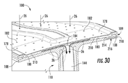
図30は、図29に示した典型的な一体型燃焼器ノズル100のうちの1つの外側ライナセグメント108の一部分の拡大図を示している。図31は、図29に示した典型的な一体型燃焼器ノズル100のうちの1つの内側ライナセグメント106の一部分の拡大図を示している。
FIG. 30 shows an enlarged view of a portion of the
特定の実施形態においては、図30に示されるように、外側衝突パネル178を、外側ライナセグメント108の外面180から半径方向に離間させ、両者の間に冷却流すき間210を形成することができる。冷却流すき間210は、対応する燃料噴射パネル100の下流端部分114と上流端部分112との間に延在することができる。動作時に、図30に示されるように、圧縮機吐出ケーシング32(図2)からの空気26が、外側衝突パネル178に対して流れ、衝突孔182を通過する。衝突孔182は、空気26の複数のジェットを、個別の位置において外側ライナセグメント108の外面180に衝突し、かつ/または外側ライナセグメント108の外面180を横切るように導き、外側ライナセグメント108の外面180のジェット冷却または衝突冷却をもたらす。次いで、空気26は、外側ライナセグメント108の上流端部分112の入口184を通り、燃料噴射パネル110の内部に定められた予混合空気プレナム144へと流入でき、予混合空気プレナム144において、個々の正圧側予混合チャネル132および/または負圧側予混合チャネル134へと分配されてよい。外側ライナセグメント108は、その長手方向の縁の各々に沿って、C字形のスロット109を定めることができ、スロット109の長さに沿ってシール(図示せず)を設置することで、隣接する外側ライナセグメント108間の接合部122をシールすることができる。
In certain embodiments, as shown in FIG. 30, the
図31に示されるように、内側衝突パネル188を、内側ライナセグメント106の外面190から半径方向に離間させ、両者の間に冷却流すき間212を形成することができる。冷却流すき間212は、対応する燃料噴射パネル100の下流端部分114と上流端部分112との間に延在することができる。動作時に、図31に示されるように、圧縮機吐出ケーシング32からの空気26が、内側衝突パネル188に対して流れ、衝突孔192を通過する。衝突孔192は、空気の複数のジェットを、個別の位置において内側ライナセグメント106の外面190に衝突し、かつ/または内側ライナセグメント106の外面190を横切るように導き、内側ライナセグメント106の外面190のジェット冷却または衝突冷却をもたらす。次いで、空気26は、内側ライナセグメント106の上流端部分112の入口194を通り、燃料噴射パネル110の内部に定められた予混合空気プレナム144へと流入でき、予混合空気プレナム144において、個々の正圧側予混合チャネル132および/または負圧側予混合チャネル134へと分配されてよい。内側ライナセグメント106は、その長手方向の縁の各々に沿って、C字形のスロット107を定めることができ、スロット107の長さに沿ってシール(図示せず)を設置することで、隣接する内側ライナセグメント106間の接合部122をシールすることができる。
As shown in FIG. 31, the
図30および図31は、それぞれ外側ライナセグメント108および/または内側ライナセグメント106を通って延びる少なくとも1つのマイクロチャネル冷却通路216をさらに示している。マイクロチャネル冷却通路216は、(図30に示されるように)冷却流すき間210に連通し、あるいは(図31に示されるように)予混合空気プレナムに連通する入口孔214を有する。マイクロチャネル冷却通路216は、それぞれのライナセグメント106または108の長手方向の縁に沿って位置することができる空気出口孔218を終端とする。
30 and 31 further show at least one
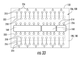
図32および図33は、本開示の特定の実施形態による内側ライナセグメント106または外側ライナセグメント108の一部分の例示となるように意図されている。特定の実施形態においては、図32および図33に示されるように、内側ライナセグメント106の外面190および/または外側ライナセグメント108の外面180が、圧縮機吐出ケーシング32(図2)からの空気を受け入れる複数の空気入口孔214を定め、あるいは含むことができる。各々の入口孔214(図33において斜線で示されている)を、対応する空気出口孔218(図33において実線の円で示されている)を終端とする比較的短いマイクロチャネル冷却通路216と一体にすることができる。図示の実施形態において、入口孔214および対応する出口孔218は、それぞれのライナセグメント108,106の同じ面(すなわち、外面180,190)に配置される。しかしながら、他の実施形態においては、出口孔218が内面に配置されてもよい。
32 and 33 are intended to illustrate a portion of the
マイクロチャネル冷却通路216の長さは、さまざまであってよい。特定の実施形態においては、マイクロチャネル冷却通路216の一部またはすべての長さが、約10インチ未満であってよい。特定の実施形態においては、マイクロチャネル冷却通路216の一部またはすべての長さが、約6インチ未満であってよい。特定の実施形態においては、マイクロチャネル冷却通路216の一部またはすべての長さが、約2インチ未満であってよい。特定の実施形態においては、マイクロチャネル冷却通路216の一部またはすべての長さが、約1インチ未満であってよい。一般に、マイクロチャネル冷却通路216は、0.5インチ〜6インチの間の長さを有することができる。種々のマイクロチャネル冷却通路216の長さを、マイクロチャネル冷却通路216の直径、マイクロチャネル冷却通路216を通って流れる空気の熱回収能力、およびライナセグメント106、108の冷却対象領域の局所温度によって決定することができる。
The length of the
特定の実施形態において、空気出口孔218のうちの1つ以上は、それぞれの内側ライナセグメント106または外側ライナセグメント108の外面190,180に沿って位置することができ、それぞれの入口孔214からの空気を収集トラフ220(図32)へともたらすことができる。図32に示されるように、収集トラフ220は、内側ライナセグメント106のそれぞれの外面190または外側ライナセグメント108の外面180に沿って延びるダクト222によって定めることが可能である。収集トラフ220は、空気の少なくとも一部を燃料噴射パネル110の予混合空気プレナム144(図31)へと導くことができ、予混合空気プレナム144において、空気を種々の正圧側予混合チャネル132および/または負圧側予混合チャネル134へと分配することができる。マイクロチャネル冷却に関するさらなる詳細は、本出願と譲受人が共通である2015年11月18日に出願された米国特許出願第14/944,341号に記載されている。
In certain embodiments, one or more of the air outlet holes 218 can be located along the
特定の実施形態においては、図32に示されるように、マイクロチャネル冷却通路216のうちの1つ以上を、1つ以上の空気空洞160の開口部162,164で終わるように配置することができる。したがって、マイクロチャネル冷却通路216のうちの1つ以上からの空気を、衝突空気インサートを内部に有していても、有していなくてもよい燃料噴射パネル110の内部を冷却するために使用される空気と、混合することができる。特定の実施形態においては、図30および図31に示されるように、空気がマイクロチャネル冷却通路216を通って流れ、次いで2つの円周方向に隣接する内側ライナセグメント106または外側ライナセグメント108の間を分割線122(図28)に沿って流れることで、両者の間の流体シールを生み出すように、1つ以上のマイクロチャネル冷却通路216の出口孔218を、内側ライナセグメント106の側壁または外側ライナセグメント108の側壁に沿って配置することができる。一実施形態においては、空気がマイクロチャネル冷却通路216を通って流れ、次いで主燃焼ゾーン102または二次燃焼ゾーン104のいずれかにフィルム空気として進入するように、1つ以上のマイクロチャネル冷却通路216の出口孔218を、内側ライナセグメント106の内面または外側ライナセグメント108の内面に沿って配置することができる。
In certain embodiments, as shown in FIG. 32, one or more of the
さらに、衝突冷却またはマイクロチャネル冷却によるライナセグメント106,108の冷却に代えて(あるいは、これに加えて)、ライナセグメント106,108を対流によって冷却することも考えられる。この構成(図示せず)においては、ライナセグメント106,108に相応に形作られた冷却スリーブが設けられることで、ライナセグメントとスリーブとの間に環状部が定められる。スリーブの後端に、空気26を環状部に進入させて予混合空気プレナム144へと上流に運ぶことを可能にする複数の冷却入口孔が設けられる。ライナセグメント106,108の外面および/またはスリーブの内面に、乱流発生部、くぼみ、ピン、山形紋、などの熱伝達用の造作を設けて、ライナセグメント106,108からの熱の移動を増大させることができる。空気26が環状部を通過し、熱伝達用の造作を過ぎ、あるいは熱伝達用の造作の周囲を過ぎるとき、空気は、それぞれのライナセグメント106,108を対流によって冷却する。次いで、空気26は、予混合空気プレナム144に進入し、集合管燃料ノズル302または予混合チャネル132,134の一方または両方において燃料と混合される。空気が予混合チャネル132,134へと導かれる場合、空気は、チャネル132、134を通って流れるときにチャネル132、134をさらに冷却する。
Further, instead of (or in addition to) cooling the
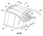
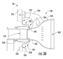
図34は、本開示の少なくとも1つの実施形態による分割型環状燃焼システム36の負圧側の一部分の斜視図を示している。図35は、本開示の1つの実施形態による1つの典型的な一体型燃焼器ノズル100の一部分の下方からの斜視図を示している。図36は、本開示の一実施形態による分割型環状燃焼システム36内に取り付けられた典型的な一体型燃焼器ノズル100の断面側面図を示している。
FIG. 34 shows a perspective view of a portion of the split
図34に示されるとおりの一実施形態において、各々の一体型燃焼器ノズル100は、対応する外側ライナセグメント108に取り付けられた取り付けストラット224を含む。一体型燃焼器ノズル100を燃焼部16内に支持するために、各々の取り付けストラット224は、外側取り付けリング226に取り付けられている。外側取り付けリング226が、ライナセグメント108の後端に図示されているが、取り付けストラット224を、取り付けリング226の(図36のような)ライナセグメント108の前端への配置あるいは前端と後端との間の中間の何らかの位置への配置を可能にするように構成できることを、理解すべきである。
In one embodiment as shown in FIG. 34, each
特定の実施形態においては、図34、図35、および図36に共同で示されるように、各々の一体型燃焼器ノズル100が、内側フックまたはフックプレート228と、外側フックまたはフックプレート252とを含むことができる。内側フック228は、内側ライナセグメント106に沿って配置されても、内側ライナセグメント106に取り付けられても、あるいは内側ライナセグメント106のうちのタービンノズル120に近接する部分を形成してもよい。外側フック252は、外側ライナセグメント108に沿って配置されても、外側ライナセグメント108に取り付けられても、あるいは外側ライナセグメント108のうちのタービンノズル120に近接する部分を形成してもよい。図36に示されるように、各々の内側フック228を、内側取り付けリング230に結合させることができる。内側フック228および外側フック252は、対向するように配置されてもよいし、反対の軸方向に延びてもよい。
In certain embodiments, each
特定の実施形態においては、図36に示されるように、外側二重蛇腹シール232が、タービンノズル120の付近において外側取り付けリング226と外側ライナセグメント108との間に延在する。外側二重蛇腹シール232の一端部234を、外側取り付けリング226に結合させることができ、あるいは外側取り付けリング226に対してシールすることができる。外側二重蛇腹シール232の第2の端部236を、外側ライナセグメント108または外側ライナセグメント108に取り付けられた中間構造体に結合させることができ、あるいは外側ライナセグメント108または外側ライナセグメント108に取り付けられた中間構造体に対してシールすることができる。他の実施形態においては、外側二重蛇腹シール232を1つ以上のリーフシールで置き換えることができる。
In certain embodiments, as shown in FIG. 36, an outer double bellows
特定の実施形態においては、内側二重蛇腹シール238が、タービンノズル120の付近において内側取り付けリング230と内側ライナセグメント106との間に延在する。内側二重蛇腹シール238の一端部240を、内側取り付けリング230に結合させることができ、あるいは内側取り付けリング230に対してシールすることができる。内側二重蛇腹シール238の第2の端部242を、内側ライナセグメント106または内側ライナセグメント106に取り付けられた中間構造体に結合させることができ、あるいは内側ライナセグメント106または内側ライナセグメント106に取り付けられた中間構造体に対してシールすることができる。他の実施形態においては、内側二重蛇腹シール238を1つ以上のリーフシールで置き換えることができる。
In certain embodiments, an inner double bellows
図37は、円周方向に隣接する1対の二重蛇腹シールの斜視図を示しており、少なくとも1つの実施形態による内側または外側二重蛇腹シール238,232のいずれかの例示となるように意図されている。内側および/または外側二重蛇腹シール238,232を、2つの蛇腹セグメント244および246を溶接または他の方法によって接合することによって製造することができる。内側および/または外側二重蛇腹シール238,232(または、リーフシール)は、軸方向および半径方向の両方において、内側取り付けリング230と一体型燃焼器ノズル100との間の動き、および/または外側取り付けリング226と一体型燃焼器ノズル100との間の動きに適応することができる。内側二重蛇腹シール238または外側二重蛇腹シール232(または、代わりのリーフシール)の各々またはいくつかは、円周方向において2つ以上の一体型燃焼器ノズル100にまたがることができる。特定の実施形態においては、中間二重蛇腹シール248(または、リーフシール)を、円周方向に隣接する二重蛇腹(または、リーフ)シールの間に形成され得るすき間250を覆って配置することができる。
FIG. 37 shows a perspective view of a pair of double bellows seals flanking adjacent in the circumferential direction, to illustrate any of the inner or outer double bellows seals 238,232 according to at least one embodiment. Intended. Inner and / or outer double bellows seals 238,232 can be manufactured by welding or otherwise joining the two
図38は、本開示の1つの実施形態による典型的な一体型燃焼器ノズル100の正圧側の斜視図を示している。図39は、図38に示したとおりの一体型燃焼器ノズル100の一部の断面斜視図を示している。一実施形態においては、図35および図38に示されるように、一体型燃焼器ノズル100が、内側フックまたはフックプレート228を含む。内側フック228は、内側ライナセグメント106に沿って配置されても、内側ライナセグメント106に取り付けられても、あるいは内側ライナセグメント106のうちのタービンノズル120に近接する部分を形成してもよい。さらに、一体型燃焼器ノズル100は、タービンノズル120に近接した外側ライナセグメント108の外面180に沿って定められた1つ以上の外側フック252を含むことができる。
FIG. 38 shows a perspective view of the positive pressure side of a typical
図38および図39に示されるように、一体型燃焼器ノズル100は、一体型燃焼器ノズル100の上流端112に近い内側ライナセグメント106の外面190に沿って配置された取り付けほぞまたは根元254をさらに含む。特定の実施形態においては、図38に示されるように、内側ライナセグメント106に取り付けられた取り付けほぞ254に代え、あるいは内側ライナセグメント106に取り付けられた取り付けほぞ254に加えて、別の取り付けほぞ254を、一体型燃焼器ノズル100の上流端112に近い外側ライナセグメント108の外面180に沿って配置でき、さらには/あるいは一体型燃焼器ノズル100の上流端112に近い外側ライナセグメント108の外面180に取り付けることができる。特定の実施形態において、取り付けほぞ254(内側ライナセグメント106または外側ライナセグメント108あるいは両方のいずれに位置するかにかかわらず)は、蟻ほぞの形状またはモミの木の形状を有することができる。
As shown in FIGS. 38 and 39, the
図40は、本開示の1つの実施形態による分割型環状燃焼システム36の一部分の斜視図を示している。図41は、一実施形態による図40に示した分割型環状燃焼システム36の一部分の断面側面図を示している。図40および図41に共同で示されるように、分割型環状燃焼システム36を、外側取り付けリング226および内側取り付けリング230に取り付けることができる。
FIG. 40 shows a perspective view of a part of the split type
図40および図41に共同で示されるように、内側スロット256および外側スロット258が、内側フック228および外側フック252をそれぞれ受け入れるために、内側取り付けリング230および外側取り付けリング226のそれぞれの垂直面部分260,262に設けられ、さらには/あるいは定められる。上述のように、内側フック228および外側フック252は、対向するように配置されてもよいし、反対の軸方向に延びてもよい。内側スロットカバー264が、内側スロット256内の内側フック228を覆い、あるいは固定することができる。内側スロットカバー264を、内側フック228を所定の位置に固定するために、内側取り付けリング230にボルトで取り付け、あるいは他の方法で結合させることができる。内側スロットカバー266が、外側スロット258内の外側フック252を覆い、あるいは固定することができる。外側スロットカバー266を、外側フック252を所定の位置に固定するために、外側取り付けリング226にボルトで取り付け、あるいは他の方法で結合させることができる。
As jointly shown in FIGS. 40 and 41, the
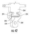
(図41に示される)種々の実施形態において、内側ライナセグメント106上の取り付けほぞ254を、取り付けほぞ254を受け入れるように形作られたスロット270を含むほぞ取り付け部269内に据えることができる。次に、ほぞ取り付け部269を、機械的な締結具272(ボルトまたはピンなど)によって、内側前方取り付けリング268に結合させることができる。図42が、本開示の少なくとも1つの実施形態による取り付けフランジのスロット270内に取り付けられた典型的なほぞ254の断面の下流側への斜視図を示している。
In various embodiments (shown in FIG. 41), the mounting
特定の実施形態においては、図42に示されるように、ダンパ274(ばね、ばねシール、または減衰メッシュ材料、など)を、各々のスロット270においてスロットの壁とほぞ254との間に配置することができる。ダンパ274は、この接合部または境界面における振動を低減することにより、長期にわたってほぞ254の摩耗を減らし、機械的な寿命および/または性能を改善する。
In certain embodiments, a damper 274 (such as a spring, spring seal, or damping mesh material, etc.) is placed between the slot wall and the
本明細書において説明および図示した分割型環状燃焼システム36、とりわけ燃料噴射モジュール300と組み合わせられた一体型燃焼器ノズル100の種々の実施形態は、従来からの環状燃焼システムと比べて、動作およびターンダウン性能のさまざまな向上または改良を提供する。例えば、分割型環状燃焼システム36の始動時に、イグナイタ364が、複数の管322のうちの管322の出口328から流れる燃料および空気混合物に点火する。出力の需要が増すとき、燃料噴射パネル110へと供給を行う燃料噴射ランス304の一部またはすべてへの燃料を、各々の燃料噴射パネル110が完全に動作するまで、同時または順次にオンにすることができる。
Various embodiments of the split-type
出力を減少させるために、燃料噴射ランス304の一部またはすべてへと流れる燃料を、必要に応じて、同または順次に絞ることができる。燃料噴射パネル110のうちのいくつかをオフにすることが望まれ、あるいは必要になるとき、1つおきの燃料噴射パネル110の燃料噴射ランス304を遮断することにより、タービンの動作の乱れを最少にすることができる。
In order to reduce the output, the fuel flowing to a part or all of the
燃料噴射モジュール300の特定の構成に応じて、負圧側予混合チャネル134へと供給を行う燃料噴射ランス304をオフにすることができる一方で、正圧側予混合チャネル132へと供給を行う燃料噴射ランス304への燃料を続けることができる。燃料噴射モジュール300の特定の構成に応じて、正圧側予混合チャネル132へと供給を行う燃料噴射ランス304をオフにすることができる一方で、負圧側予混合チャネル134へと供給を行う燃料噴射ランス304への燃料を続けることができる。燃料噴射モジュール300の特定の構成に応じて、1つおきの燃料噴射パネル110へと供給を行う燃料噴射ランス304をオフにすることができる一方で、交互の燃料噴射パネル110へと供給を行う燃料噴射ランス304への燃料を続けることができる。
Depending on the particular configuration of the
特定の実施形態においては、1つ以上の燃料噴射パネル110について、燃料噴射ランス304の半径方向内側の(または、第1の)サブセット340への燃料を遮断し、あるいは燃料噴射ランス304の半径方向外側の(または、第2の)サブセット344への燃料を遮断することができる。特定の実施形態においては、1つ以上の燃料噴射パネル110の燃料噴射ランス304の第1のサブセット340への燃料または燃料噴射ランス304の第2のサブセット344への燃料を、すべての燃料噴射ランス304がオフにされ、集合管燃料ノズル部分302にのみ燃料がもたらされるようになるまで、交互のパターン(半径方向内側/半径方向外側/半径方向内側/など)にてオフにすることができる。他の実施形態においては、燃料ランス304および集合管燃料ノズル部分302の燃料供給の有無のさまざまな組み合わせを、所望のレベルのターンダウンを達成するために使用することができる。
In certain embodiments, for one or more
本開示および添付の図面の全体を通して、個別の燃料ランス304を有する燃料噴射モジュール300に言及してきたが、燃料ランス304を、予混合チャネル132,134とやり取りをする燃料噴射モジュール300内の燃料マニホールド、または予混合チャネル132、134へと燃料をもたらす燃料噴射パネル110内に位置する燃料マニホールドによって、置き換えてもよいと考えられる。さらに、燃料マニホールドを、燃料(または、燃料−空気混合物)が出口126,128による導入に先立って燃料噴射パネル110の後端を冷却するように、燃料噴射パネル110の後端に向かって配置してもよいと考えられる。
Although the
燃料を、燃焼器のさまざまな動作モードにおいて、分割型環状燃焼システム36の燃料噴射パネル110のうちの1つ以上および/または燃料噴射モジュール300のうちの1つ以上へと供給できることを、理解すべきである。円周方向に隣接する燃料噴射パネル110または円周方向に隣接する燃料噴射モジュール300の各々について、同時に燃料を供給する必要はなく、あるいは同時に燃焼させる必要はない。したがって、分割型環状燃焼システム36の特定の動作モードにおいて、各々の個別の燃料噴射パネル110および/または各々の燃料噴射モジュール300、あるいは燃料噴射パネル110のランダムなサブセットおよび/または燃料噴射モジュール300のランダムなサブセットを、別個独立にオンライン(燃料がもたらされる)にし、あるいは遮断し、さらには同様または異なる燃料流量とすることで、始動、ターンダウン、ベース負荷、全負荷、および他の動作条件などの動作モードに向けた動作の柔軟性をもたらすことができる。
Understand that fuel can be supplied to one or more of the
本明細書は、本発明を最良の態様を含めて開示するとともに、あらゆる装置またはシステムの製作および使用ならびにあらゆる関連の方法の実行を含む本発明の実施を当業者にとって可能にするために、実施例を用いている。本発明の特許可能な範囲は、特許請求の範囲によって定められ、当業者であれば想到できる他の実施例を含むことができる。そのような他の実施例は、それらが特許請求の範囲の文言から相違しない構造要素を有しており、あるいは特許請求の範囲の文言から実質的には相違しない同等の構造要素を含むならば、特許請求の範囲の技術的範囲に包含される。
[実施態様1]
内側ライナセグメント(106)と、外側ライナセグメント(108)と、第1の側壁(116)と、第2の側壁(118)と、これらの間に定められた複数の予混合チャネル(132、134)と、前記複数の予混合チャネル(132、134)に流体連通した複数の噴射出口(126、128)と、第1のタービンノズル(120)を定める下流端部分(114)とを含む第1の一体型燃焼器ノズル(100)と、
前記第1の一体型燃焼器ノズル(100)に隣接した第2の一体型燃焼器ノズル(100)であって、内側ライナセグメント(106)と、外側ライナセグメント(108)と、第1の側壁(116)と、第2の側壁(118)と、これらの間に定められた複数の予混合チャネル(132、134)と、前記複数の予混合チャネル(132、134)に流体連通した複数の噴射出口(126、128)と、第2のタービンノズル(120)を定める下流端部分(114)とを含む第2の一体型燃焼器ノズル(100)と、
前記第1の一体型燃焼器ノズル(100)の前記第2の側壁(118)と前記第2の一体型燃焼器ノズル(100)の前記第1の側壁(116)との間に配置された燃料ノズル部分(302)と、燃料供給部ならびに前記第1の一体型燃焼器ノズル(100)の前記複数の予混合チャネル(132、134)および前記第2の一体型燃焼器ノズル(100)の前記複数の予混合チャネル(132、134)のうちの少なくとも1つに流体連通した少なくとも1つの燃料噴射ランス(304)とを含んでいる第1の燃料噴射モジュール(300)と
を備える、環状燃焼システム(36)のセグメント。
[実施態様2]
前記少なくとも1つの燃料噴射ランス(304)は、複数の燃料噴射ランス(304)を含む、実施態様1に記載の環状燃焼システム(36)のセグメント。
[実施態様3]
前記燃料供給部および前記第1の燃料噴射モジュール(300)に結合した導管(346)をさらに備え、前記導管(346)は、前記集合管燃料ノズル部分(302)および前記複数の燃料噴射ランス(304)の少なくとも一方に燃料をもたらす、実施態様2に記載の環状燃焼システム(36)のセグメント。
[実施態様4]
前記第1の一体型燃焼器ノズル(100)の前記第1の側壁(116)および前記第2の一体型燃焼器ノズル(100)の前記第1の側壁(116)は、正圧側側壁(116)であり、前記第1の一体型燃焼器ノズル(100)の前記第2の側壁(118)および前記第2の一体型燃焼器ノズル(100)の前記第2の側壁(118)は、負圧側側壁(118)である、実施態様1に記載の環状燃焼システム(36)のセグメント。
[実施態様5]
前記第1の一体型燃焼器ノズル(100)は、前記負圧側側壁(118)に沿って半径方向に間隔を空けつつ配置された複数の負圧側噴射出口(128)を含み、前記第1の一体型燃焼器ノズル(100)の前記負圧側噴射出口(128)は、前記第1の一体型燃焼器ノズル(100)と前記第2の一体型燃焼器ノズル(100)との間に定められる主燃焼ゾーン(102)の下流の半径方向の噴射面(131)を定めている、実施態様4に記載の環状燃焼システム(36)のセグメント。
[実施態様6]
前記第2の一体型燃焼器ノズル(100)は、前記正圧側側壁(116)に沿って半径方向に間隔を空けつつ配置された複数の正圧側噴射出口(126)を含み、前記第2の一体型燃焼器ノズル(100)の前記正圧側噴射出口(126)は、前記第1の一体型燃焼器ノズル(100)と前記第2の一体型燃焼器ノズル(100)との間に定められる主燃焼ゾーン(102)の下流の半径方向の噴射面(130)を定めている、実施態様4に記載の環状燃焼システム(36)のセグメント。
[実施態様7]
前記第1の一体型燃焼器ノズル(100)は、前記負圧側側壁(118)に沿って半径方向に間隔を空けつつ配置された複数の負圧側噴射出口(128)を含み、各々の負圧側噴射出口(128)は、前記第1の一体型燃焼器ノズル(100)の前記複数の予混合チャネル(132、134)のうちのそれぞれの予混合チャネル(134)に流体連通しており、前記第2の一体型燃焼器ノズル(100)は、前記正圧側側壁(116)に沿って半径方向に間隔を空けつつ配置された複数の正圧側噴射出口(126)を含み、各々の正圧側噴射出口(126)は、前記第2の一体型燃焼器ノズル(100)の前記複数の予混合チャネル(132、134)のうちのそれぞれの予混合チャネル(132)に流体連通している、実施態様4に記載の環状燃焼システム(36)のセグメント。
[実施態様8]
燃料噴射モジュール(300)の外壁(320)の周囲に延在するシール(324)をさらに備える、実施態様1に記載の環状燃焼システム(36)のセグメント。
[実施態様9]
複数の一体型燃焼器ノズル(100)と、
複数の燃料噴射モジュール(300)と
を備える環状燃焼システム(36)であって、
前記複数の一体型燃焼器ノズル(100)は、前記燃焼システム(36)の軸方向の中心線の周囲に環状に並べて配置され、各々の一体型燃焼器ノズル(100)が、翼形の形状を有するタービンノズル(120)を定める下流端部分(114)を有する燃料噴射パネル(110)を含んでおり、
前記複数の燃料噴射モジュール(300)の各々の燃料噴射モジュール(300)は、その少なくとも一部分が、前記複数の一体型燃焼器ノズル(100)のうちの隣り合う一体型燃焼器ノズル(100)のそれぞれのペアの間、かつ前記隣り合う一体型燃焼器ノズル(100)の間に定められるそれぞれの主燃焼ゾーン(102)の下流に配置されている、環状燃焼システム(36)。
[実施態様10]
各々の燃料噴射モジュール(300)は、集合管燃料ノズル部分(302)および複数の燃料噴射ランス(304)を備え、前記複数の燃料噴射ランス(304)は、前記複数の一体型燃焼器ノズル(100)のうちのそれぞれの一体型燃焼器ノズル(100)の燃料噴射パネル(110)に流体連通している、実施態様9に記載の環状燃焼システム(36)。
[実施態様11]
各々の燃料噴射パネル(110)は、正圧側側壁(116)と、負圧側側壁(118)と、前記正圧側側壁(116)と前記負圧側側壁(118)との間に定められた複数の予混合チャネル(132、134)と、前記複数の予混合チャネル(132、134)に流体連通した複数の噴射出口(126、128)とを含み、前記複数の噴射出口(126、128)は、前記正圧側側壁(116)に沿って定められた少なくとも1つの正圧側噴射出口(126)と、前記負圧側側壁(118)に沿って定められた少なくとも1つの負圧側噴射出口(126)とを含む、実施態様9に記載の環状燃焼システム(36)。
[実施態様12]
前記複数の一体型燃焼器ノズル(100)の各々の一体型燃焼器ノズル(100)は、内側ライナセグメント(106)および外側ライナセグメント(108)を含み、前記内側ライナセグメント(106)および前記外側ライナセグメント(108)は、前記燃料噴射パネル(110)と一体に形成されている、実施態様9に記載の環状燃焼システム(36)。
[実施態様13]
前記環状燃焼システム(36)は、ガスタービン(10)の燃焼部(16)内に配置される、実施態様9に記載の環状燃焼システム(36)。
[実施態様14]
内側ライナ(106)および前記内側ライナ(106)の半径方向外側に配置された外側ライナ(108)と、
複数の燃料ノズルと、
複数の燃料噴射パネル(110)と
を備える環状燃焼システム(36)であって、
前記内側ライナ(106)および前記外側ライナ(108)は、前記燃焼システム(36)の中心線を囲む環状部を前記内側ライナ(106)と前記外側ライナ(108)との間に定めており、前記環状部は、前記環状部の上流端に位置する複数の主燃焼ゾーン(102)と、前記主燃焼ゾーン(102)の下流の複数の二次燃焼ゾーン(104)とを含み、
前記複数の燃料ノズルのうちの少なくとも1つの燃料ノズルは、前記複数の主燃焼ゾーン(102)の各々の主燃焼ゾーン(102)に可燃性混合物を吐出し、
前記複数の燃料噴射パネル(110)の各々の燃料噴射パネル(110)は、隣り合う燃料ノズルの間に少なくとも部分的に配置され、少なくとも1つの二次燃焼ゾーン(104)に可燃性混合物を吐出し、各々の燃料噴射パネル(110)は、隣り合う主燃焼ゾーン(102)を隔て、隣り合う二次燃焼ゾーン(104)も隔てるように、軸方向に下流の方向へと延びており、
各々の燃料噴射パネル(110)は、タービンノズル(120)を定める後端(114)を有している、環状燃焼システム(36)。
[実施態様15]
前記内側ライナ(106)および前記外側ライナ(108)は、分割されている、実施態様14に記載の環状燃焼システム(36)。
[実施態様16]
前記複数の燃料ノズルの各々の燃料ノズルは、円周方向において前記複数のパネル燃料インジェクタ(110)のうちの隣り合うパネル壁インジェクタ(110)の間を延びている集合管燃料ノズル(302)であり、各々の集合管燃料ノズル(320)は、前方プレート(316)と、後方プレート(318)と、前記前方プレート(316)と前記後方プレート(318)との間を軸方向に延びている外シュラウド(320)と、前記外シュラウド(320)の内側に定められた燃料プレナム(332)と、前記前方プレート(316)、前記燃料プレナム(332)、および前記後方プレート(318)を通って延びている複数の予混合管(322)とを備えている、実施態様14に記載の環状燃焼システム(36)。
[実施態様17]
各々の燃料ノズルは、半径方向において前記内側ライナ(106)と前記外側ライナ(108)との間を延びている、実施態様16に記載の環状燃焼システム(36)。
[実施態様18]
各々の燃料噴射パネル(110)は、半径方向において前記内側ライナ(106)と前記外側ライナ(108)との間を延びている、実施態様14に記載の環状燃焼システム(36)。
[実施態様19]
前記複数の燃料噴射パネル(110)の各々の燃料噴射パネル(110)は、第1の側壁(116)と、前記第1の側壁(116)の反対側の第2の側壁(118)と、前記第1の側壁(116)と前記第2の側壁(118)とを接続する後端(114)とを備え、前記第1の側壁(116)、前記第2の側壁(118)、および前記後端(114)は、これらの間に予混合空気プレナムおよび燃料プレナムを定め、複数の予混合チャネル(132、134)が、前記第1の側壁(116)と前記第2の側壁(118)との間に配置され、前記複数の予混合チャネル(132、134)の各々の予混合チャネル(132、134)は、前記予混合空気プレナムおよび前記燃料プレナムに連通し、前記第1の側壁(116)および前記第2の側壁(118)の一方に形成された噴射孔(126、128)を有している、実施態様14に記載の環状燃焼システム(36)。
[実施態様20]
前記複数の燃料噴射パネル(110)の各々の燃料噴射パネル(110)における前記複数の予混合チャネル(132、134)は、第1の側の予混合チャネル(132)を含み、前記第1の側の予混合チャネル(132)の前記噴射孔(126)は、それぞれの燃料噴射パネル(110)の前記第1の側壁(116)を貫いて定められている、実施態様19に記載の環状燃焼システム(36)。
The present specification is carried out in order to disclose the present invention including the best aspects and to enable those skilled in the art to carry out the present invention including the manufacture and use of any device or system and the execution of all related methods. An example is used. The patentable scope of the present invention is defined by the scope of claims and may include other embodiments conceivable by those skilled in the art. Such other embodiments have equivalent structural elements that do not differ substantially from the wording of the claims, or if they contain equivalent structural elements that do not substantially differ from the wording of the claims. , It is included in the technical scope of the claims.
[Embodiment 1]
An inner liner segment (106), an outer liner segment (108), a first side wall (116), a second side wall (118), and a plurality of premixed channels (132, 134) defined between them. ), A plurality of injection outlets (126, 128) in which fluid communicates with the plurality of premix channels (132, 134), and a first downstream end portion (114) defining the first turbine nozzle (120). Integrated combustor nozzle (100) and
A second integrated combustor nozzle (100) adjacent to the first integrated combustor nozzle (100), the inner liner segment (106), the outer liner segment (108), and the first side wall. (116), a second side wall (118), a plurality of premixed channels (132, 134) defined between them, and a plurality of fluid communication to the plurality of premixed channels (132, 134). A second integrated combustor nozzle (100), including an injection outlet (126, 128) and a downstream end portion (114) defining a second turbine nozzle (120).
Arranged between the second side wall (118) of the first integrated combustor nozzle (100) and the first side wall (116) of the second integrated combustor nozzle (100). Of the fuel nozzle portion (302), the fuel supply section, the plurality of premix channels (132, 134) of the first integrated combustor nozzle (100), and the second integrated combustor nozzle (100). Circular combustion comprising a first fuel injection module (300) comprising at least one fuel injection lance (304) fluidally communicated to at least one of the plurality of premixed channels (132, 134). Segment of system (36).
[Embodiment 2]
The segment of the annular combustion system (36) according to embodiment 1, wherein the at least one fuel injection lance (304) comprises a plurality of fuel injection lances (304).
[Embodiment 3]
A conduit (346) coupled to the fuel supply unit and the first fuel injection module (300) is further provided, and the conduit (346) includes the collecting pipe fuel nozzle portion (302) and the plurality of fuel injection lances (34). The segment of the annular combustion system (36) according to embodiment 2, which provides fuel to at least one of 304).
[Embodiment 4]
The first side wall (116) of the first integrated combustor nozzle (100) and the first side wall (116) of the second integrated combustor nozzle (100) are positive pressure side side walls (116). The second side wall (118) of the first integrated combustor nozzle (100) and the second side wall (118) of the second integrated combustor nozzle (100) are negative. The segment of the annular combustion system (36) according to embodiment 1, which is the compression side side wall (118).
[Embodiment 5]
The first integrated combustor nozzle (100) includes a plurality of negative pressure side injection outlets (128) arranged radially spaced along the negative pressure side side wall (118). The negative pressure side injection outlet (128) of the integrated combustor nozzle (100) is defined between the first integrated combustor nozzle (100) and the second integrated combustor nozzle (100). The segment of the annular combustion system (36) according to embodiment 4, which defines a radial injection surface (131) downstream of the main combustion zone (102).
[Embodiment 6]
The second integrated combustor nozzle (100) includes a plurality of positive pressure side injection outlets (126) arranged radially spaced along the positive pressure side side wall (116). The positive pressure side injection outlet (126) of the integrated combustor nozzle (100) is defined between the first integrated combustor nozzle (100) and the second integrated combustor nozzle (100). The segment of the annular combustion system (36) according to embodiment 4, which defines a radial injection surface (130) downstream of the main combustion zone (102).
[Embodiment 7]
The first integrated combustor nozzle (100) includes a plurality of negative pressure side injection outlets (128) arranged radially spaced along the negative pressure side side wall (118), and each negative pressure side. The injection outlet (128) fluidly communicates with each of the premixed channels (134) of the plurality of premixed channels (132, 134) of the first integrated combustor nozzle (100). The second integrated combustor nozzle (100) includes a plurality of positive pressure side injection outlets (126) arranged radially spaced along the positive pressure side side wall (116), and each positive pressure side injection. An embodiment in which the outlet (126) fluidly communicates with each of the premixed channels (132) of the plurality of premixed channels (132, 134) of the second integrated combustor nozzle (100). Section 4 of the annular combustion system (36).
[Embodiment 8]
The segment of the annular combustion system (36) according to embodiment 1, further comprising a seal (324) extending around the outer wall (320) of the fuel injection module (300).
[Embodiment 9]
With multiple integrated combustor nozzles (100),
An annular combustion system (36) with a plurality of fuel injection modules (300).
The plurality of integrated combustor nozzles (100) are arranged side by side in an annular shape around the axial center line of the combustion system (36), and each integrated combustor nozzle (100) has a blade shape. Includes a fuel injection panel (110) with a downstream end portion (114) defining a turbine nozzle (120) with.
Each fuel injection module (300) of the plurality of fuel injection modules (300) has at least a part thereof of an adjacent integrated combustor nozzle (100) among the plurality of integrated combustor nozzles (100). An annular combustion system (36) located downstream of each main combustion zone (102) defined between each pair and between the adjacent integrated combustor nozzles (100).
[Embodiment 10]
Each fuel injection module (300) comprises a collecting pipe fuel nozzle portion (302) and a plurality of fuel injection lances (304), and the plurality of fuel injection lances (304) include the plurality of integrated combustor nozzles (304). The annular combustion system (36) according to embodiment 9, wherein the fluid is communicated with the fuel injection panel (110) of each of the integrated combustor nozzles (100) of 100).
[Embodiment 11]
Each fuel injection panel (110) has a plurality of defined side walls (116) on the positive pressure side, a side wall on the negative pressure side (118), and a plurality of side walls on the positive pressure side (116) and the side wall on the negative pressure side (118). The plurality of injection outlets (126, 128) include a premixing channel (132, 134) and a plurality of injection outlets (126, 128) in which the fluid is communicated with the plurality of premixing channels (132, 134). At least one positive pressure side injection outlet (126) defined along the positive pressure side side wall (116) and at least one negative pressure side injection outlet (126) defined along the negative pressure side side wall (118). The annular combustion system (36) according to embodiment 9, which includes.
[Embodiment 12]
Each integrated combustor nozzle (100) of the plurality of integrated combustor nozzles (100) includes an inner liner segment (106) and an outer liner segment (108), the inner liner segment (106) and the outer side. The annular combustion system (36) according to embodiment 9, wherein the liner segment (108) is integrally formed with the fuel injection panel (110).
[Embodiment 13]
The annular combustion system (36) according to embodiment 9, wherein the annular combustion system (36) is arranged in a combustion unit (16) of the gas turbine (10).
[Embodiment 14]
An inner liner (106) and an outer liner (108) arranged radially outside the inner liner (106),
With multiple fuel nozzles
An annular combustion system (36) with a plurality of fuel injection panels (110).
The inner liner (106) and the outer liner (108) define an annular portion surrounding the center line of the combustion system (36) between the inner liner (106) and the outer liner (108). The annular portion includes a plurality of main combustion zones (102) located at the upstream end of the annular portion and a plurality of secondary combustion zones (104) downstream of the main combustion zone (102).
At least one of the plurality of fuel nozzles discharges a flammable mixture into each main combustion zone (102) of the plurality of main combustion zones (102).
Each fuel injection panel (110) of the plurality of fuel injection panels (110) is arranged at least partially between adjacent fuel nozzles and discharges a flammable mixture into at least one secondary combustion zone (104). However, each fuel injection panel (110) extends in the downstream direction in the axial direction so as to separate the adjacent main combustion zone (102) and the adjacent secondary combustion zone (104).
Each fuel injection panel (110) has a rear end (114) that defines a turbine nozzle (120), an annular combustion system (36).
[Embodiment 15]
The annular combustion system (36) according to
[Embodiment 16]
Each fuel nozzle of the plurality of fuel nozzles is a collecting pipe fuel nozzle (302) extending between adjacent panel wall injectors (110) among the plurality of panel fuel injectors (110) in the circumferential direction. There, each collecting pipe fuel nozzle (320) extends axially between the front plate (316), the rear plate (318), and the front plate (316) and the rear plate (318). Through the outer shroud (320), the fuel plenum (332) defined inside the outer shroud (320), the front plate (316), the fuel plenum (332), and the rear plate (318). 13. The annular combustion system (36) according to
[Embodiment 17]
16. The annular combustion system (36) of
[Embodiment 18]
13. The annular combustion system (36) of
[Embodiment 19]
Each fuel injection panel (110) of the plurality of fuel injection panels (110) has a first side wall (116) and a second side wall (118) opposite to the first side wall (116). It comprises a rear end (114) connecting the first side wall (116) and the second side wall (118), the first side wall (116), the second side wall (118), and the said. The rear end (114) defines a premixed air plenum and a fuel plenum between them, and a plurality of premixed channels (132, 134) have the first side wall (116) and the second side wall (118). Each of the premixed channels (132, 134) of the plurality of premixed channels (132, 134) communicates with the premixed air plenum and the fuel plenum, and the first side wall (the first side wall (132, 134). The annular combustion system (36) according to
[Embodiment 20]
The plurality of premixed channels (132, 134) in each fuel injection panel (110) of the plurality of fuel injection panels (110) include the first side premixed channel (132), and the first one. The annular combustion according to embodiment 19, wherein the injection hole (126) of the side premixing channel (132) is defined through the first side wall (116) of each fuel injection panel (110). System (36).
10 ガスタービン
12 吸気部
14 圧縮機
16 燃焼部
18 タービン
20 排気部
22 シャフト
24 空気
26 圧縮空気
28 燃料
30 燃焼ガス
32 圧縮機吐出ケーシング
34 高圧プレナム
36 分割型環状燃焼システム
38 中心線
40 端部カバー
100 一体型燃焼器ノズル
102 主燃焼ゾーン
104 二次燃焼ゾーン
106 内側ライナセグメント
107 スロット
108 外側ライナセグメント
109 スロット
110 燃料噴射パネル
112 上流端部分
114 下流端部分
116 第1の(正圧側)側壁
118 第2の(負圧側)側壁
120 タービンノズル
122 軸方向の分割線
124 シールド
126 正圧側噴射出口
128 負圧側噴射出口
130 正圧側噴射面
131 負圧側噴射面
132 正圧側予混合チャネル
134 負圧側予混合チャネル
136 (正圧側予混合チャネルの)一直線の部分
138 (正圧側予混合チャネルの)湾曲した部分
140 (負圧側予混合チャネルの)一直線の部分
142 (負圧側予混合チャネルの)湾曲した部分
144 予混合空気プレナム
146 環状のカラーまたは座
148 ストラット
150 テーパ部
151 中央開口部
152 流路
154 浮動カラー
156 クロスファイヤ管
157 空気供給孔
158 パージ空気孔
160 空気空洞
162 開口部
164 開口部
166 壁
168 開口
170 空気空洞
178 外側衝突パネル
180 (外側ライナセグメントの)外面
182 衝突孔
184 (予混合空気プレナムへの)入口
186 開口部
188 内側衝突パネル
190 (内側ライナセグメントの)外面
192 衝突孔
194 (予混合空気プレナムへの)入口
196 開口部
198 第1の衝突インサート
200 衝突孔
202 第2の衝突インサート
204 空洞
206 (第2の衝突インサートの)半径方向内側の端部
208 (第2の衝突インサートの)半径方向外側の端部
210 冷却流すき間
212 冷却流すき間
214 入口孔
216 マイクロチャネル冷却通路
218 出口孔
220 収集トラフ
222 ダクト
224 取り付けストラット
226 取り付けリング
228 内側フックプレート
230 内側取り付けリング
232 外側二重蛇腹シール
234 (外側二重蛇腹シールの)一端部
236 (外側二重蛇腹シールの)第2の端部
238 内側二重蛇腹シール
240 (内側二重蛇腹シールの)一端部
242 (内側二重蛇腹シールの)第2の端部
244 蛇腹セグメント
246 蛇腹セグメント
248 中間二重蛇腹シール
250 すき間
252 外側フック
254 取り付けほぞ
256 内側スロット
258 外側スロット
260 (内側取り付けリングの)垂直面部分
262 (外側取り付けリングの)垂直面部分
264 内側スロットカバー
266 外側スロットカバー
268 内側前方取り付けリング
269 ほぞ取り付け部
270 スロット
272 締結具
274 ダンパ
300 燃料噴射モジュール
302 燃料ノズル部分
304 燃料噴射ランス
304a (燃料噴射ランスの)半径方向外側のサブセット
304b (燃料噴射ランスの)中間のサブセット
304c (燃料噴射ランスの)半径方向内側のサブセット
306 下流端部分
308 送出先端部
310 噴射ポート
312 蛇腹部分またはカバー
314 ハウジング本体
316 前方プレート
318 後方プレート
320 外周壁
322 管
324 シール
326 (管の)入口
328 (管の)出口
330 予混合通路
332 燃料ノズルプレナム
332a 前方の燃料ノズルプレナム
332b 後方の燃料ノズルプレナム
334 燃料ポート
336 インジェクタ燃料プレナム
338 第1のインジェクタ燃料プレナム
340 (燃料噴射ランスの)第1のサブセット
342 第2のインジェクタ燃料プレナム
344 (燃料噴射ランスの)第2のサブセット
346 導管
348 外側管
350 内側管
352 外側燃料回路
354 内側燃料回路
356 (管の)第1のサブセット
358 (管の)第2のサブセット
360 第1の後方プレート
362 第2の後方プレート
364 イグナイタ
366 シール
368 周壁
370 第1の集合管燃料プレナム
371 壁
372 第2の集合管燃料プレナム
373 壁
374 第1のインジェクタ燃料プレナム
376 第2のインジェクタ燃料プレナム
378 (燃料噴射ランスの)第1のサブセット
380 (燃料噴射ランスの)第2のサブセット
382 燃料導管
384 外側管
386 内側管
388 内側燃料回路
390 外側燃料回路
392 燃料導管
394 外側管
396 内側管
398 内側燃料回路
400 外側燃料回路
402 燃料噴射モジュールセット
404 導管
406 導管
408 燃料供給導管
410 外側導管
412 内側導管
414 液体燃料カートリッジ
416 中間導管
418 空気プレナム
420 開口部
422 内側燃料通路
424 液体燃料
426 外側燃料通路
428 パージ空気通路
430 パージ空気
432 環状のすき間
434 液体燃料
436 液体燃料カートリッジ
437 保護管
438 外側燃料通路
439 環状部
10 Gas turbine 12 Intake part 14 Compressor 16 Combustion part 18 Turbine 20 Exhaust part 22 Shaft 24 Air 26 Compressed air 28 Fuel 30 Combustion gas 32 Compressor discharge casing 34 High pressure plenum 36 Split type annular combustion system 38 Center line 40 End cover 100 Integrated compressor nozzle 102 Main combustion zone 104 Secondary combustion zone 106 Inner liner segment 107 Slot 108 Outer liner segment 109 Slot 110 Fuel injection panel 112 Upstream end portion 114 Downstream end portion 116 First (positive pressure side) side wall 118 2 (negative pressure side) side wall 120 Turbine nozzle 122 Axial dividing line 124 Shield 126 Positive pressure side injection outlet 128 Negative pressure side injection outlet 130 Positive pressure side injection surface 131 Negative pressure side injection surface 132 Positive pressure side premix channel 134 Negative pressure side premix channel 136 Straight part (of the positive pressure side premixed channel) Curved part 140 (of the positive pressure side premixed channel) Straight part 142 (of the negative pressure side premixed channel) Curved part 144 (of the negative pressure side premixed channel) Mixed Air Plenum 146 Circular Collar or Seat 148 Strut 150 Tapered 151 Central Opening 152 Channel 154 Floating Collar 156 Crossfire Tube 157 Air Supply Hole 158 Purge Air Hole 160 Air Cavity 162 Opening 164 Opening 166 Wall 168 Opening 170 Air Cavity 178 Outer Collision Panel 180 (Outer Liner Segment) Outer Surface 182 Collision Hole 184 (Premixed Air Plenum) Inlet 186 Opening 188 Inner Collision Panel 190 (Inner Liner Segment) Outer Surface 192 Collision Hole 194 (Premixed Air) Inlet 196 (to plenum) Opening 198 First collision insert 200 Collision hole 202 Second collision insert 204 Cavity 206 Radial inner end 208 (of second collision insert) Radius (of second collision insert) Direction Outer end 210 Cooling flow gap 212 Cooling flow gap 214 Inlet hole 216 Microchannel cooling passage 218 Exit hole 220 Collection trough 222 Duct 224 Mounting strut 226 Mounting ring 228 Inner hook plate 230 Inner mounting ring 232 Outer double bellows seal 234 One end 236 (of the outer double bellows seal) Second end 238 (of the outer double bellows seal) Inner double bellows seal 240 (inner double bellows) One end 242 (of the seal) Second end (of the inner double bellows seal) 244 Bellows segment 246 Bellows segment 248 Intermediate double bellows seal 250 Gap 252 Outer hook 254 Mounting groove 256 Inner slot 258 Outer slot 260 (Inner mounting ring) Vertical surface part 262 (of the outer mounting ring) Vertical surface part 264 Inner slot cover 266 Outer slot cover 268 Inner front mounting ring 269 Groove mounting part 270 Slot 272 Fastener 274 Damper 300 Fuel injection module 302 Fuel nozzle part 304 Fuel injection Lance 304a Radial outer subset 304 (fuel injection lance) Intermediate subset 304c (fuel injection lance) Radial inner subset 306 Downstream end 308 Delivery tip 310 Injection port 312 Bellows or Cover 314 Housing Body 316 Front Plate 318 Rear Plate 320 Outer Wall 322 Pipe 324 Seal 326 (Pipe) Inlet 328 (Pipe) Exit 330 Premix Passage 332 Fuel Nozzle Plenum 332a Front Fuel Nozzle Plenum 332b Rear Fuel Nozzle Plenum 334 Fuel port 336 Injector fuel plenum 338 First injector fuel plenum 340 (of fuel injection lance) First subset 342 Second injector fuel plenum 344 (of fuel injection lance) Second subset 346 Conduit 348 Outer pipe 350 Inner pipe 352 Outer fuel circuit 354 Inner fuel circuit 356 (pipe) first subset 358 (tube) second subset 360 first rear plate 362 second rear plate 364 igniter 366 seal 368 perimeter wall 370 first assembly tube Fuel Plenum 371 Wall 372 Second assembly pipe Fuel Plenum 373 Wall 374 First injector Fuel Plenum 376 Second injector Fuel Plenum 378 (of fuel injection lance) First subset 380 (of fuel injection lance) Second subset 382 Fuel conduit 384 Outer tube 386 Inner tube 388 Inner fuel circuit 390 Outer fuel circuit 392 Fuel conduit 394 Outer tube 396 Inner tube 398 Inner fuel circuit 400 Outer fuel circuit 402 Fuel injection module set 404 Conduit 406 Conduit 408 Fuel supply conduit 410 Outer conduit 412 Inner conduit 414 Liquid Fuel cartridge 416 Intermediate conduit 418 Air plenum 420 Opening 422 Inner fuel passage 424 Liquid fuel 426 Outer fuel passage 428 Purge air passage 430 Purge air 432 Circular gap 434 Liquid fuel 436 Liquid fuel cartridge 437 Protective pipe 438 Outer fuel passage 439 Circular part
Claims (9)
内側ライナセグメント(106)と、外側ライナセグメント(108)と、第1の側壁(116)と、第2の側壁(118)と、これらの間に定められた複数の予混合チャネル(132、134)と、前記複数の予混合チャネル(132、134)に流体連通した複数の噴射出口(126、128)と、第1のタービンノズル(120)を定める下流端部分(114)とを含む第1の一体型燃焼器ノズル(100)と、
前記第1の一体型燃焼器ノズル(100)に隣接した第2の一体型燃焼器ノズル(100)であって、内側ライナセグメント(106)と、外側ライナセグメント(108)と、第1の側壁(116)と、第2の側壁(118)と、これらの間に定められた複数の予混合チャネル(132、134)と、前記複数の予混合チャネル(132、134)に流体連通した複数の噴射出口(126、128)と、第2のタービンノズル(120)を定める下流端部分(114)とを含む第2の一体型燃焼器ノズル(100)と、
前記第1の一体型燃焼器ノズル(100)の前記第2の側壁(118)と前記第2の一体型燃焼器ノズル(100)の前記第1の側壁(116)との間に配置された燃料ノズル部分(302)と、燃料供給部ならびに前記第1の一体型燃焼器ノズル(100)の前記複数の予混合チャネル(132、134)および前記第2の一体型燃焼器ノズル(100)の前記複数の予混合チャネル(132、134)のうちの少なくとも1つに流体連通した少なくとも1つの燃料噴射ランス(304)とを含んでいる第1の燃料噴射モジュール(300)と
を備え、
前記燃料ノズル部分(302)からの燃料が前記多段化された環状燃焼システム(36)の第1段に供給され、
前記少なくとも1つの燃料噴射ランス(304)からの燃料が前記多段化された環状燃焼システム(36)の他の段に供給される、環状燃焼システム(36)のセグメント。 A segment of the annular combustion system (36) that is multi-staged in the axial direction.
An inner liner segment (106), an outer liner segment (108), a first side wall (116), a second side wall (118), and a plurality of premixed channels (132, 134) defined between them. ), A plurality of injection outlets (126, 128) in which fluid communicates with the plurality of premix channels (132, 134), and a first downstream end portion (114) defining the first turbine nozzle (120). Integrated combustor nozzle (100) and
A second integrated combustor nozzle (100) adjacent to the first integrated combustor nozzle (100), the inner liner segment (106), the outer liner segment (108), and the first side wall. (116), a second side wall (118), a plurality of premixed channels (132, 134) defined between them, and a plurality of fluid communication to the plurality of premixed channels (132, 134). A second integrated combustor nozzle (100), including an injection outlet (126, 128) and a downstream end portion (114) defining a second turbine nozzle (120).
Arranged between the second side wall (118) of the first integrated combustor nozzle (100) and the first side wall (116) of the second integrated combustor nozzle (100). Of the fuel nozzle portion (302), the fuel supply section, the plurality of premixed channels (132, 134) of the first integrated combustor nozzle (100), and the second integrated combustor nozzle (100). It comprises a first fuel injection module (300) comprising at least one fuel injection lance (304) fluidally connected to at least one of the plurality of premixed channels (132, 134) .
The fuel from the fuel nozzle portion (302) is supplied to the first stage of the multi-stage annular combustion system (36).
Wherein Ru fuel from at least one fuel injection lance (304) is supplied to the other stages of the multi-stage is an annular combustion system (36), the segment of the annular combustion system (36).
前記第1の一体型燃焼器ノズル(100)に隣接した第2の一体型燃焼器ノズル(100)であって、内側ライナセグメント(106)と、外側ライナセグメント(108)と、第1の側壁(116)と、第2の側壁(118)と、これらの間に定められた複数の予混合チャネル(132、134)と、前記複数の予混合チャネル(132、134)に流体連通した複数の噴射出口(126、128)と、第2のタービンノズル(120)を定める下流端部分(114)とを含む第2の一体型燃焼器ノズル(100)と、
前記第1の一体型燃焼器ノズル(100)の前記第2の側壁(118)と前記第2の一体型燃焼器ノズル(100)の前記第1の側壁(116)との間に配置された燃料ノズル部分(302)と、燃料供給部ならびに前記第1の一体型燃焼器ノズル(100)の前記複数の予混合チャネル(132、134)および前記第2の一体型燃焼器ノズル(100)の前記複数の予混合チャネル(132、134)のうちの少なくとも1つに流体連通した少なくとも1つの燃料噴射ランス(304)とを含んでいる第1の燃料噴射モジュール(300)と
を備え、
前記第1の一体型燃焼器ノズル(100)の前記第1の側壁(116)および前記第2の一体型燃焼器ノズル(100)の前記第1の側壁(116)は、正圧側側壁(116)であり、前記第1の一体型燃焼器ノズル(100)の前記第2の側壁(118)および前記第2の一体型燃焼器ノズル(100)の前記第2の側壁(118)は、負圧側側壁(118)である、環状燃焼システム(36)のセグメント。 An inner liner segment (106), an outer liner segment (108), a first side wall (116), a second side wall (118), and a plurality of premixed channels (132, 134) defined between them. ), A plurality of injection outlets (126, 128) in which fluid communicates with the plurality of premix channels (132, 134), and a first downstream end portion (114) defining the first turbine nozzle (120). Integrated combustor nozzle (100) and
A second integrated combustor nozzle (100) adjacent to the first integrated combustor nozzle (100), the inner liner segment (106), the outer liner segment (108), and the first side wall. (116), a second side wall (118), a plurality of premixed channels (132, 134) defined between them, and a plurality of fluid communication to the plurality of premixed channels (132, 134). A second integrated combustor nozzle (100), including an injection outlet (126, 128) and a downstream end portion (114) defining a second turbine nozzle (120).
Arranged between the second side wall (118) of the first integrated combustor nozzle (100) and the first side wall (116) of the second integrated combustor nozzle (100). Of the fuel nozzle portion (302), the fuel supply section, the plurality of premixed channels (132, 134) of the first integrated combustor nozzle (100), and the second integrated combustor nozzle (100). With a first fuel injection module (300) comprising at least one fuel injection lance (304) fluid-permeable to at least one of the plurality of premixed channels (132, 134).
Equipped with
The first side wall (116) of the first integrated combustor nozzle (100) and the first side wall (116) of the second integrated combustor nozzle (100) are positive pressure side side walls (116). The second side wall (118) of the first integrated combustor nozzle (100) and the second side wall (118) of the second integrated combustor nozzle (100) are negative. A segment of the annular combustion system (36) , which is the compression side sidewall (118).
前記第1の一体型燃焼器ノズル(100)に隣接した第2の一体型燃焼器ノズル(100)であって、内側ライナセグメント(106)と、外側ライナセグメント(108)と、第1の側壁(116)と、第2の側壁(118)と、これらの間に定められた複数の予混合チャネル(132、134)と、前記複数の予混合チャネル(132、134)に流体連通した複数の噴射出口(126、128)と、第2のタービンノズル(120)を定める下流端部分(114)とを含む第2の一体型燃焼器ノズル(100)と、
前記第1の一体型燃焼器ノズル(100)の前記第2の側壁(118)と前記第2の一体型燃焼器ノズル(100)の前記第1の側壁(116)との間に配置された燃料ノズル部分(302)と、燃料供給部ならびに前記第1の一体型燃焼器ノズル(100)の前記複数の予混合チャネル(132、134)および前記第2の一体型燃焼器ノズル(100)の前記複数の予混合チャネル(132、134)のうちの少なくとも1つに流体連通した少なくとも1つの燃料噴射ランス(304)とを含んでいる第1の燃料噴射モジュール(300)と、
燃料噴射モジュール(300)の外壁(320)の周囲に延在するシール(324)と、を備える、環状燃焼システム(36)のセグメント。 An inner liner segment (106), an outer liner segment (108), a first side wall (116), a second side wall (118), and a plurality of premixed channels (132, 134) defined between them. ), A plurality of injection outlets (126, 128) in which fluid communicates with the plurality of premix channels (132, 134), and a first downstream end portion (114) defining the first turbine nozzle (120). Integrated combustor nozzle (100) and
A second integrated combustor nozzle (100) adjacent to the first integrated combustor nozzle (100), the inner liner segment (106), the outer liner segment (108), and the first side wall. (116), a second side wall (118), a plurality of premixed channels (132, 134) defined between them, and a plurality of fluid communication to the plurality of premixed channels (132, 134). A second integrated combustor nozzle (100), including an injection outlet (126, 128) and a downstream end portion (114) defining a second turbine nozzle (120).
Arranged between the second side wall (118) of the first integrated combustor nozzle (100) and the first side wall (116) of the second integrated combustor nozzle (100). Of the fuel nozzle portion (302), the fuel supply section, the plurality of premixed channels (132, 134) of the first integrated combustor nozzle (100), and the second integrated combustor nozzle (100). A first fuel injection module (300) comprising at least one fuel injection lance (304) fluidally connected to at least one of the plurality of premixed channels (132, 134).
Comprises a seal (324) extending around the outer wall (320) of the fuel injection module (300), a segment of an annular combustion system (36).
複数の燃料噴射モジュール(300)と
を備える環状燃焼システム(36)であって、
前記複数の一体型燃焼器ノズル(100)は、前記燃焼システム(36)の軸方向の中心線の周囲に環状に並べて配置され、各々の一体型燃焼器ノズル(100)が、翼形の形状を有するタービンノズル(120)を定める下流端部分(114)を有する燃料噴射パネル(110)を含んでおり、
前記複数の燃料噴射モジュール(300)の各々の燃料噴射モジュール(300)は、その少なくとも一部分が、前記複数の一体型燃焼器ノズル(100)のうちの隣り合う一体型燃焼器ノズル(100)のそれぞれのペアの間、かつ前記隣り合う一体型燃焼器ノズル(100)の間に定められるそれぞれの主燃焼ゾーン(102)の下流に配置されている、環状燃焼システム(36)。 With multiple integrated combustor nozzles (100),
An annular combustion system (36) with a plurality of fuel injection modules (300).
The plurality of integrated combustor nozzles (100) are arranged side by side in an annular shape around the axial center line of the combustion system (36), and each integrated combustor nozzle (100) has a blade shape. Includes a fuel injection panel (110) with a downstream end portion (114) defining a turbine nozzle (120) with.
Each fuel injection module (300) of the plurality of fuel injection modules (300) has at least a part thereof of an adjacent integrated combustor nozzle (100) among the plurality of integrated combustor nozzles (100). An annular combustion system (36) located downstream of each main combustion zone (102) defined between each pair and between the adjacent integrated combustor nozzles (100).
Applications Claiming Priority (5)
| Application Number | Priority Date | Filing Date | Title |
|---|---|---|---|
| US201662313232P | 2016-03-25 | 2016-03-25 | |
| US62/313,232 | 2016-03-25 | ||
| US15/464,394 | 2017-03-21 | ||
| US15/464,394 US10690056B2 (en) | 2016-03-25 | 2017-03-21 | Segmented annular combustion system with axial fuel staging |
| PCT/US2017/024231 WO2017165876A2 (en) | 2016-03-25 | 2017-03-27 | Segmented annular combustion system with axial fuel staging |
Publications (2)
| Publication Number | Publication Date |
|---|---|
| JP2019509460A JP2019509460A (en) | 2019-04-04 |
| JP6972004B2 true JP6972004B2 (en) | 2021-11-24 |
Family
ID=59896395
Family Applications (2)
| Application Number | Title | Priority Date | Filing Date |
|---|---|---|---|
| JP2018548828A Active JP6835868B2 (en) | 2016-03-25 | 2017-03-01 | Combustion system with panel fuel injector |
| JP2018548827A Active JP6972004B2 (en) | 2016-03-25 | 2017-03-27 | Split-type annular combustion system with multi-stage fuel in the axial direction |
Family Applications Before (1)
| Application Number | Title | Priority Date | Filing Date |
|---|---|---|---|
| JP2018548828A Active JP6835868B2 (en) | 2016-03-25 | 2017-03-01 | Combustion system with panel fuel injector |
Country Status (6)
| Country | Link |
|---|---|
| US (7) | US10641175B2 (en) |
| EP (3) | EP3433539B1 (en) |
| JP (2) | JP6835868B2 (en) |
| KR (2) | KR102334882B1 (en) |
| CN (2) | CN109196279B (en) |
| WO (2) | WO2017165092A1 (en) |
Families Citing this family (45)
| Publication number | Priority date | Publication date | Assignee | Title |
|---|---|---|---|---|
| EP3059499B1 (en) * | 2013-10-18 | 2019-04-10 | Mitsubishi Heavy Industries, Ltd. | Fuel injector |
| US10641491B2 (en) * | 2016-03-25 | 2020-05-05 | General Electric Company | Cooling of integrated combustor nozzle of segmented annular combustion system |
| US10641175B2 (en) * | 2016-03-25 | 2020-05-05 | General Electric Company | Panel fuel injector |
| US11156362B2 (en) | 2016-11-28 | 2021-10-26 | General Electric Company | Combustor with axially staged fuel injection |
| US11231175B2 (en) * | 2018-06-19 | 2022-01-25 | General Electric Company | Integrated combustor nozzles with continuously curved liner segments |
| US11248705B2 (en) | 2018-06-19 | 2022-02-15 | General Electric Company | Curved seal with relief cuts for adjacent gas turbine components |
| US11047248B2 (en) | 2018-06-19 | 2021-06-29 | General Electric Company | Curved seal for adjacent gas turbine components |
| US11248789B2 (en) | 2018-12-07 | 2022-02-15 | Raytheon Technologies Corporation | Gas turbine engine with integral combustion liner and turbine nozzle |
| US11174792B2 (en) | 2019-05-21 | 2021-11-16 | General Electric Company | System and method for high frequency acoustic dampers with baffles |
| US11156164B2 (en) | 2019-05-21 | 2021-10-26 | General Electric Company | System and method for high frequency accoustic dampers with caps |
| JP7145837B2 (en) * | 2019-10-16 | 2022-10-03 | 株式会社神戸製鋼所 | Reactor and reaction system provided with the same |
| CN110919013A (en) * | 2019-12-11 | 2020-03-27 | 湖南天际智慧材料科技有限公司 | Metal powder flame spheroidizing equipment and processing technology thereof |
| US11828467B2 (en) | 2019-12-31 | 2023-11-28 | General Electric Company | Fluid mixing apparatus using high- and low-pressure fluid streams |
| US11287134B2 (en) | 2019-12-31 | 2022-03-29 | General Electric Company | Combustor with dual pressure premixing nozzles |
| US12553385B2 (en) * | 2020-03-30 | 2026-02-17 | Ge Vernova Infrastructure Technology Llc | Compact turbomachine combustor |
| JP7272989B2 (en) * | 2020-03-31 | 2023-05-12 | 三菱重工業株式会社 | Method for manufacturing gas turbine combustor and burner parts |
| JP7349403B2 (en) * | 2020-04-22 | 2023-09-22 | 三菱重工業株式会社 | Burner assembly, gas turbine combustor and gas turbine |
| CN111894738B (en) * | 2020-07-16 | 2021-09-07 | 北京航空航天大学 | Injection device, engine and injection device design method |
| US11460191B2 (en) | 2020-08-31 | 2022-10-04 | General Electric Company | Cooling insert for a turbomachine |
| US11614233B2 (en) | 2020-08-31 | 2023-03-28 | General Electric Company | Impingement panel support structure and method of manufacture |
| US11371702B2 (en) | 2020-08-31 | 2022-06-28 | General Electric Company | Impingement panel for a turbomachine |
| US11994293B2 (en) * | 2020-08-31 | 2024-05-28 | General Electric Company | Impingement cooling apparatus support structure and method of manufacture |
| US11994292B2 (en) | 2020-08-31 | 2024-05-28 | General Electric Company | Impingement cooling apparatus for turbomachine |
| US11668242B2 (en) * | 2020-09-29 | 2023-06-06 | General Electric Company | Fuel injection assembly for a turbomachine |
| US11255545B1 (en) | 2020-10-26 | 2022-02-22 | General Electric Company | Integrated combustion nozzle having a unified head end |
| CN112555900A (en) * | 2020-12-09 | 2021-03-26 | 南京航空航天大学 | Full-coverage air film cooling structure for wall surface of combustion chamber of micro turbojet engine |
| US11371701B1 (en) * | 2021-02-03 | 2022-06-28 | General Electric Company | Combustor for a gas turbine engine |
| KR102429075B1 (en) * | 2021-02-17 | 2022-08-03 | 두산에너빌리티 주식회사 | Micromixer bundle assembly, combustor and gas turbin comprising it |
| US11692709B2 (en) | 2021-03-11 | 2023-07-04 | General Electric Company | Gas turbine fuel mixer comprising a plurality of mini tubes for generating a fuel-air mixture |
| US12270543B2 (en) | 2021-08-20 | 2025-04-08 | Rtx Corporation | Multi-function monolithic combustion liner |
| CN114165358B (en) * | 2021-11-16 | 2023-02-03 | 北京航天动力研究所 | Baffle nozzle structure of precombustion chamber |
| EP4671609A3 (en) | 2021-12-21 | 2026-03-25 | General Electric Company | Fuel nozzle and swirler |
| US11906165B2 (en) | 2021-12-21 | 2024-02-20 | General Electric Company | Gas turbine nozzle having an inner air swirler passage and plural exterior fuel passages |
| JP7780333B2 (en) * | 2021-12-27 | 2025-12-04 | 川崎重工業株式会社 | Combustor panel and gas turbine combustor equipped with same |
| US11774100B2 (en) | 2022-01-14 | 2023-10-03 | General Electric Company | Combustor fuel nozzle assembly |
| KR102660055B1 (en) * | 2022-03-21 | 2024-04-22 | 두산에너빌리티 주식회사 | Nozzle for combustor, combustor, and gas turbine including the same |
| US11767766B1 (en) | 2022-07-29 | 2023-09-26 | General Electric Company | Turbomachine airfoil having impingement cooling passages |
| CN115355536B (en) * | 2022-08-17 | 2024-02-02 | 北京理工大学 | A hydrogen-oxygen micro-mixed combustion device suitable for gas turbines and its use method |
| US12460821B2 (en) * | 2023-02-15 | 2025-11-04 | Solar Turbines Incorporated | Fuel injector panels having micromixers |
| CN116146981B (en) * | 2023-04-17 | 2023-06-16 | 中国空气动力研究与发展中心超高速空气动力研究所 | Injection panel using air film cooling partition plate nozzle |
| CN116624894B (en) * | 2023-05-23 | 2025-06-17 | 哈尔滨工业大学 | A compact combustion chamber |
| GB202307700D0 (en) | 2023-05-23 | 2023-07-05 | Rolls Royce Plc | An improved combustor apparatus |
| GB202307701D0 (en) | 2023-05-23 | 2023-07-05 | Rolls Royce Plc | An improved combustor apparatus |
| GB202307702D0 (en) * | 2023-05-23 | 2023-07-05 | Rolls Royce Plc | An improved combustor apparatus |
| KR102863421B1 (en) * | 2023-12-15 | 2025-09-22 | 두산에너빌리티 주식회사 | Nozzle for combustor, combustor, and gas turbine including the same |
Family Cites Families (142)
| Publication number | Priority date | Publication date | Assignee | Title |
|---|---|---|---|---|
| US2595999A (en) | 1943-11-23 | 1952-05-06 | Westinghouse Electric Corp | Power plant combustion apparatus having apertured combustion chamber walls |
| US2625792A (en) | 1947-09-10 | 1953-01-20 | Rolls Royce | Flame tube having telescoping walls with fluted ends to admit air |
| US3657883A (en) | 1970-07-17 | 1972-04-25 | Westinghouse Electric Corp | Combustion chamber clustering structure |
| US3657882A (en) | 1970-11-13 | 1972-04-25 | Westinghouse Electric Corp | Combustion apparatus |
| US3750398A (en) | 1971-05-17 | 1973-08-07 | Westinghouse Electric Corp | Static seal structure |
| US4614082A (en) | 1972-12-19 | 1986-09-30 | General Electric Company | Combustion chamber construction |
| US4016718A (en) | 1975-07-21 | 1977-04-12 | United Technologies Corporation | Gas turbine engine having an improved transition duct support |
| US4112676A (en) * | 1977-04-05 | 1978-09-12 | Westinghouse Electric Corp. | Hybrid combustor with staged injection of pre-mixed fuel |
| US4195474A (en) | 1977-10-17 | 1980-04-01 | General Electric Company | Liquid-cooled transition member to turbine inlet |
| US4158949A (en) | 1977-11-25 | 1979-06-26 | General Motors Corporation | Segmented annular combustor |
| JPS5554636A (en) | 1978-10-16 | 1980-04-22 | Hitachi Ltd | Combustor of gas turbine |
| US4373327A (en) | 1979-07-04 | 1983-02-15 | Rolls-Royce Limited | Gas turbine engine combustion chambers |
| US4422288A (en) | 1981-03-02 | 1983-12-27 | General Electric Company | Aft mounting system for combustion transition duct members |
| US4413470A (en) | 1981-03-05 | 1983-11-08 | Electric Power Research Institute, Inc. | Catalytic combustion system for a stationary combustion turbine having a transition duct mounted catalytic element |
| US4720970A (en) | 1982-11-05 | 1988-01-26 | The United States Of America As Represented By The Secretary Of The Air Force | Sector airflow variable geometry combustor |
| US4819438A (en) | 1982-12-23 | 1989-04-11 | United States Of America | Steam cooled rich-burn combustor liner |
| DE3317035A1 (en) * | 1983-05-10 | 1984-11-15 | BBC Aktiengesellschaft Brown, Boveri & Cie., Baden, Aargau | MULTIPLE BURNER |
| US4719748A (en) | 1985-05-14 | 1988-01-19 | General Electric Company | Impingement cooled transition duct |
| CA1309873C (en) | 1987-04-01 | 1992-11-10 | Graham P. Butt | Gas turbine combustor transition duct forced convection cooling |
| US4843825A (en) | 1988-05-16 | 1989-07-04 | United Technologies Corporation | Combustor dome heat shield |
| US5297385A (en) | 1988-05-31 | 1994-03-29 | United Technologies Corporation | Combustor |
| JP2820558B2 (en) * | 1991-10-22 | 1998-11-05 | 三菱重工業株式会社 | Combustor and turbine vane integrated gas turbine |
| US5239818A (en) * | 1992-03-30 | 1993-08-31 | General Electric Company | Dilution pole combustor and method |
| US5237813A (en) | 1992-08-21 | 1993-08-24 | Allied-Signal Inc. | Annular combustor with outer transition liner cooling |
| FR2695460B1 (en) * | 1992-09-09 | 1994-10-21 | Snecma | Combustion chamber of a turbomachine with several injectors. |
| JP2904701B2 (en) * | 1993-12-15 | 1999-06-14 | 株式会社日立製作所 | Gas turbine and gas turbine combustion device |
| JPH07190370A (en) * | 1993-12-28 | 1995-07-28 | Hitachi Ltd | Hybrid type combustor for gas combustion |
| US5415000A (en) * | 1994-06-13 | 1995-05-16 | Westinghouse Electric Corporation | Low NOx combustor retro-fit system for gas turbines |
| EP0718468B1 (en) | 1994-12-20 | 2001-10-31 | General Electric Company | Transition piece frame support |
| US5924288A (en) | 1994-12-22 | 1999-07-20 | General Electric Company | One-piece combustor cowl |
| US5836164A (en) * | 1995-01-30 | 1998-11-17 | Hitachi, Ltd. | Gas turbine combustor |
| WO1996027766A1 (en) * | 1995-03-08 | 1996-09-12 | Bmw Rolls-Royce Gmbh | Axially stepped double-ring combustion chamber for a gas turbine |
| US5749229A (en) | 1995-10-13 | 1998-05-12 | General Electric Company | Thermal spreading combustor liner |
| US5826430A (en) | 1996-04-23 | 1998-10-27 | Westinghouse Electric Corporation | Fuel heating system used in conjunction with steam cooled combustors and transitions |
| US6047550A (en) * | 1996-05-02 | 2000-04-11 | General Electric Co. | Premixing dry low NOx emissions combustor with lean direct injection of gas fuel |
| JP3276289B2 (en) | 1996-05-13 | 2002-04-22 | 三菱重工業株式会社 | Gas turbine combustor |
| JP3500020B2 (en) | 1996-11-29 | 2004-02-23 | 三菱重工業株式会社 | Steam cooled gas turbine system |
| DE19654472A1 (en) | 1996-12-27 | 1998-07-02 | Asea Brown Boveri | Process for cooling thermally highly loaded units of a gas turbine group |
| US5906093A (en) | 1997-02-21 | 1999-05-25 | Siemens Westinghouse Power Corporation | Gas turbine combustor transition |
| DE29714742U1 (en) | 1997-08-18 | 1998-12-17 | Siemens AG, 80333 München | Heat shield component with cooling fluid return and heat shield arrangement for a hot gas-carrying component |
| US6116013A (en) | 1998-01-02 | 2000-09-12 | Siemens Westinghouse Power Corporation | Bolted gas turbine combustor transition coupling |
| DE59903398D1 (en) | 1998-03-20 | 2002-12-19 | Siemens Ag | GAS TURBINE BURNER |
| US6098397A (en) | 1998-06-08 | 2000-08-08 | Caterpillar Inc. | Combustor for a low-emissions gas turbine engine |
| US6082111A (en) | 1998-06-11 | 2000-07-04 | Siemens Westinghouse Power Corporation | Annular premix section for dry low-NOx combustors |
| US6339923B1 (en) * | 1998-10-09 | 2002-01-22 | General Electric Company | Fuel air mixer for a radial dome in a gas turbine engine combustor |
| JP2001041005A (en) | 1999-08-02 | 2001-02-13 | Tohoku Electric Power Co Inc | Piping support of gas turbine steam cooled combustor |
| US6412268B1 (en) | 2000-04-06 | 2002-07-02 | General Electric Company | Cooling air recycling for gas turbine transition duct end frame and related method |
| JP2001289062A (en) | 2000-04-07 | 2001-10-19 | Mitsubishi Heavy Ind Ltd | Wall surface cooling structure for gas turbine combustor |
| IT1317978B1 (en) | 2000-06-16 | 2003-07-21 | Nuovo Pignone Spa | TRANSITION PIECE FOR COMBUSTION CHAMBERS OF NONANULAR GAS TURBINES. |
| JP3846169B2 (en) | 2000-09-14 | 2006-11-15 | 株式会社日立製作所 | Gas turbine repair method |
| US6345494B1 (en) | 2000-09-20 | 2002-02-12 | Siemens Westinghouse Power Corporation | Side seal for combustor transitions |
| US6298656B1 (en) | 2000-09-29 | 2001-10-09 | Siemens Westinghouse Power Corporation | Compressed air steam generator for cooling combustion turbine transition section |
| JP2002206743A (en) | 2000-12-28 | 2002-07-26 | Toyota Central Res & Dev Lab Inc | Premix combustor |
| US6450762B1 (en) | 2001-01-31 | 2002-09-17 | General Electric Company | Integral aft seal for turbine applications |
| JP2002243154A (en) | 2001-02-16 | 2002-08-28 | Mitsubishi Heavy Ind Ltd | Gas turbine combustor and tail cylinder outlet structure thereof |
| JP4008212B2 (en) | 2001-06-29 | 2007-11-14 | 三菱重工業株式会社 | Hollow structure with flange |
| US6652220B2 (en) | 2001-11-15 | 2003-11-25 | General Electric Company | Methods and apparatus for cooling gas turbine nozzles |
| US6568187B1 (en) | 2001-12-10 | 2003-05-27 | Power Systems Mfg, Llc | Effusion cooled transition duct |
| JP4134311B2 (en) * | 2002-03-08 | 2008-08-20 | 独立行政法人 宇宙航空研究開発機構 | Gas turbine combustor |
| US6655147B2 (en) | 2002-04-10 | 2003-12-02 | General Electric Company | Annular one-piece corrugated liner for combustor of a gas turbine engine |
| US6619915B1 (en) | 2002-08-06 | 2003-09-16 | Power Systems Mfg, Llc | Thermally free aft frame for a transition duct |
| US6644032B1 (en) | 2002-10-22 | 2003-11-11 | Power Systems Mfg, Llc | Transition duct with enhanced profile optimization |
| GB2402715B (en) | 2003-06-10 | 2006-06-14 | Rolls Royce Plc | Gas turbine aerofoil |
| US7010921B2 (en) | 2004-06-01 | 2006-03-14 | General Electric Company | Method and apparatus for cooling combustor liner and transition piece of a gas turbine |
| US7377036B2 (en) * | 2004-10-05 | 2008-05-27 | General Electric Company | Methods for tuning fuel injection assemblies for a gas turbine fuel nozzle |
| US7310938B2 (en) | 2004-12-16 | 2007-12-25 | Siemens Power Generation, Inc. | Cooled gas turbine transition duct |
| US8015818B2 (en) | 2005-02-22 | 2011-09-13 | Siemens Energy, Inc. | Cooled transition duct for a gas turbine engine |
| US7437876B2 (en) * | 2005-03-25 | 2008-10-21 | General Electric Company | Augmenter swirler pilot |
| EP1875501A1 (en) | 2005-04-13 | 2008-01-09 | Freescale Semiconductor, Inc. | Protection of an integrated circuit and method therefor |
| US7779636B2 (en) | 2005-05-04 | 2010-08-24 | Delavan Inc | Lean direct injection atomizer for gas turbine engines |
| US7334960B2 (en) | 2005-06-23 | 2008-02-26 | Siemens Power Generation, Inc. | Attachment device for removable components in hot gas paths in a turbine engine |
| US7886517B2 (en) | 2007-05-09 | 2011-02-15 | Siemens Energy, Inc. | Impingement jets coupled to cooling channels for transition cooling |
| US7836703B2 (en) * | 2007-06-20 | 2010-11-23 | General Electric Company | Reciprocal cooled turbine nozzle |
| US8011188B2 (en) * | 2007-08-31 | 2011-09-06 | General Electric Company | Augmentor with trapped vortex cavity pilot |
| US8387398B2 (en) | 2007-09-14 | 2013-03-05 | Siemens Energy, Inc. | Apparatus and method for controlling the secondary injection of fuel |
| US7665309B2 (en) | 2007-09-14 | 2010-02-23 | Siemens Energy, Inc. | Secondary fuel delivery system |
| JP4823186B2 (en) * | 2007-09-25 | 2011-11-24 | 三菱重工業株式会社 | Gas turbine combustor |
| US8151570B2 (en) | 2007-12-06 | 2012-04-10 | Alstom Technology Ltd | Transition duct cooling feed tubes |
| US8104292B2 (en) | 2007-12-17 | 2012-01-31 | General Electric Company | Duplex turbine shroud |
| US7874138B2 (en) | 2008-09-11 | 2011-01-25 | Siemens Energy, Inc. | Segmented annular combustor |
| US8375726B2 (en) | 2008-09-24 | 2013-02-19 | Siemens Energy, Inc. | Combustor assembly in a gas turbine engine |
| US8272218B2 (en) | 2008-09-24 | 2012-09-25 | Siemens Energy, Inc. | Spiral cooled fuel nozzle |
| US8230688B2 (en) | 2008-09-29 | 2012-07-31 | Siemens Energy, Inc. | Modular transvane assembly |
| KR101366584B1 (en) | 2008-10-08 | 2014-02-24 | 미츠비시 쥬고교 가부시키가이샤 | Gas turbine and operating method therefor |
| US8549861B2 (en) | 2009-01-07 | 2013-10-08 | General Electric Company | Method and apparatus to enhance transition duct cooling in a gas turbine engine |
| US20100192582A1 (en) * | 2009-02-04 | 2010-08-05 | Robert Bland | Combustor nozzle |
| US8851402B2 (en) * | 2009-02-12 | 2014-10-07 | General Electric Company | Fuel injection for gas turbine combustors |
| US8307657B2 (en) * | 2009-03-10 | 2012-11-13 | General Electric Company | Combustor liner cooling system |
| US8904799B2 (en) | 2009-05-25 | 2014-12-09 | Majed Toqan | Tangential combustor with vaneless turbine for use on gas turbine engines |
| US8616002B2 (en) * | 2009-07-23 | 2013-12-31 | General Electric Company | Gas turbine premixing systems |
| US8281594B2 (en) | 2009-09-08 | 2012-10-09 | Siemens Energy, Inc. | Fuel injector for use in a gas turbine engine |
| JP5103454B2 (en) * | 2009-09-30 | 2012-12-19 | 株式会社日立製作所 | Combustor |
| EP2496885B1 (en) * | 2009-11-07 | 2019-05-29 | Ansaldo Energia Switzerland AG | Burner with a cooling system allowing an increased gas turbine efficiency |
| JP5479058B2 (en) * | 2009-12-07 | 2014-04-23 | 三菱重工業株式会社 | Communication structure between combustor and turbine section, and gas turbine |
| US8752386B2 (en) | 2010-05-25 | 2014-06-17 | Siemens Energy, Inc. | Air/fuel supply system for use in a gas turbine engine |
| RU2531110C2 (en) * | 2010-06-29 | 2014-10-20 | Дженерал Электрик Компани | Gas-turbine unit and unit with injector vanes (versions) |
| US8261555B2 (en) * | 2010-07-08 | 2012-09-11 | General Electric Company | Injection nozzle for a turbomachine |
| US8499566B2 (en) | 2010-08-12 | 2013-08-06 | General Electric Company | Combustor liner cooling system |
| JP5156066B2 (en) | 2010-08-27 | 2013-03-06 | 株式会社日立製作所 | Gas turbine combustor |
| EP2434222B1 (en) * | 2010-09-24 | 2019-02-27 | Ansaldo Energia IP UK Limited | Method for operating a combustion chamber |
| EP2436977A1 (en) * | 2010-09-30 | 2012-04-04 | Siemens Aktiengesellschaft | Burner for a gas turbine |
| JP5653705B2 (en) | 2010-09-30 | 2015-01-14 | 三菱重工業株式会社 | Recovery air cooling gas turbine combustor cooling structure |
| US8464537B2 (en) * | 2010-10-21 | 2013-06-18 | General Electric Company | Fuel nozzle for combustor |
| US8726668B2 (en) | 2010-12-17 | 2014-05-20 | General Electric Company | Fuel atomization dual orifice fuel nozzle |
| US8387391B2 (en) | 2010-12-17 | 2013-03-05 | General Electric Company | Aerodynamically enhanced fuel nozzle |
| US20120151928A1 (en) | 2010-12-17 | 2012-06-21 | Nayan Vinodbhai Patel | Cooling flowpath dirt deflector in fuel nozzle |
| US9719419B2 (en) | 2011-03-16 | 2017-08-01 | Mitsubishi Heavy Industries, Ltd. | Gas turbine combustor with top hat nozzle arrangements |
| US8893382B2 (en) * | 2011-09-30 | 2014-11-25 | General Electric Company | Combustion system and method of assembling the same |
| US9188335B2 (en) * | 2011-10-26 | 2015-11-17 | General Electric Company | System and method for reducing combustion dynamics and NOx in a combustor |
| FR2982008B1 (en) | 2011-10-26 | 2013-12-13 | Snecma | ANNULAR ROOM OF COMBUSTION CHAMBER WITH IMPROVED COOLING AT THE PRIMARY HOLES AND DILUTION HOLES |
| EP2613080A1 (en) | 2012-01-05 | 2013-07-10 | Siemens Aktiengesellschaft | Combustion chamber of an annular combustor for a gas turbine |
| US9016039B2 (en) * | 2012-04-05 | 2015-04-28 | General Electric Company | Combustor and method for supplying fuel to a combustor |
| US9335050B2 (en) * | 2012-09-26 | 2016-05-10 | United Technologies Corporation | Gas turbine engine combustor |
| US9599343B2 (en) * | 2012-11-28 | 2017-03-21 | General Electric Company | Fuel nozzle for use in a turbine engine and method of assembly |
| US9366437B2 (en) | 2012-12-20 | 2016-06-14 | General Electric Company | System for reducing flame holding within a combustor |
| US9435539B2 (en) * | 2013-02-06 | 2016-09-06 | General Electric Company | Variable volume combustor with pre-nozzle fuel injection system |
| WO2014141397A1 (en) * | 2013-03-13 | 2014-09-18 | 株式会社日立製作所 | Gas turbine combustor |
| US9546789B2 (en) | 2013-03-15 | 2017-01-17 | General Electric Company | System having a multi-tube fuel nozzle |
| US9458767B2 (en) * | 2013-03-18 | 2016-10-04 | General Electric Company | Fuel injection insert for a turbine nozzle segment |
| EP2796789B1 (en) * | 2013-04-26 | 2017-03-01 | General Electric Technology GmbH | Can combustor for a can-annular combustor arrangement in a gas turbine |
| WO2014191495A1 (en) | 2013-05-31 | 2014-12-04 | Siemens Aktiengesellschaft | Annular combustion chamber for a gas turbine, with tangential injection for late lean injection |
| WO2014201135A1 (en) * | 2013-06-11 | 2014-12-18 | United Technologies Corporation | Combustor with axial staging for a gas turbine engine |
| EP2837888A1 (en) * | 2013-08-15 | 2015-02-18 | Alstom Technology Ltd | Sequential combustion with dilution gas mixer |
| US9476592B2 (en) * | 2013-09-19 | 2016-10-25 | General Electric Company | System for injecting fuel in a gas turbine combustor |
| EP3059499B1 (en) * | 2013-10-18 | 2019-04-10 | Mitsubishi Heavy Industries, Ltd. | Fuel injector |
| US9518478B2 (en) * | 2013-10-28 | 2016-12-13 | General Electric Company | Microchannel exhaust for cooling and/or purging gas turbine segment gaps |
| US20150159877A1 (en) * | 2013-12-06 | 2015-06-11 | General Electric Company | Late lean injection manifold mixing system |
| US9650958B2 (en) * | 2014-07-17 | 2017-05-16 | General Electric Company | Combustor cap with cooling passage |
| US10480791B2 (en) | 2014-07-31 | 2019-11-19 | General Electric Company | Fuel injector to facilitate reduced NOx emissions in a combustor system |
| US9534786B2 (en) * | 2014-08-08 | 2017-01-03 | Pratt & Whitney Canada Corp. | Combustor heat shield |
| US10267521B2 (en) * | 2015-04-13 | 2019-04-23 | Pratt & Whitney Canada Corp. | Combustor heat shield |
| EP3081862B1 (en) * | 2015-04-13 | 2020-08-19 | Ansaldo Energia Switzerland AG | Vortex generating arrangement for a pre-mixing burner of a gas turbine and gas turbine with such vortex generating arrangement |
| US10641491B2 (en) * | 2016-03-25 | 2020-05-05 | General Electric Company | Cooling of integrated combustor nozzle of segmented annular combustion system |
| US10830442B2 (en) * | 2016-03-25 | 2020-11-10 | General Electric Company | Segmented annular combustion system with dual fuel capability |
| US10520194B2 (en) * | 2016-03-25 | 2019-12-31 | General Electric Company | Radially stacked fuel injection module for a segmented annular combustion system |
| US10605459B2 (en) * | 2016-03-25 | 2020-03-31 | General Electric Company | Integrated combustor nozzle for a segmented annular combustion system |
| US10584880B2 (en) * | 2016-03-25 | 2020-03-10 | General Electric Company | Mounting of integrated combustor nozzles in a segmented annular combustion system |
| US10563869B2 (en) * | 2016-03-25 | 2020-02-18 | General Electric Company | Operation and turndown of a segmented annular combustion system |
| US11428413B2 (en) * | 2016-03-25 | 2022-08-30 | General Electric Company | Fuel injection module for segmented annular combustion system |
| US10584876B2 (en) * | 2016-03-25 | 2020-03-10 | General Electric Company | Micro-channel cooling of integrated combustor nozzle of a segmented annular combustion system |
| US10641175B2 (en) * | 2016-03-25 | 2020-05-05 | General Electric Company | Panel fuel injector |
| US10690350B2 (en) * | 2016-11-28 | 2020-06-23 | General Electric Company | Combustor with axially staged fuel injection |
-
2017
- 2017-02-24 US US15/442,227 patent/US10641175B2/en active Active
- 2017-02-24 US US15/442,292 patent/US10655541B2/en active Active
- 2017-02-24 US US15/442,171 patent/US10724441B2/en active Active
- 2017-02-24 US US15/442,255 patent/US10641176B2/en active Active
- 2017-02-24 US US15/442,203 patent/US11002190B2/en active Active
- 2017-02-24 US US15/442,269 patent/US10584638B2/en active Active
- 2017-03-01 CN CN201780032272.1A patent/CN109196279B/en active Active
- 2017-03-01 KR KR1020187030782A patent/KR102334882B1/en active Active
- 2017-03-01 EP EP17711434.5A patent/EP3433539B1/en active Active
- 2017-03-01 EP EP23020043.8A patent/EP4220014B1/en active Active
- 2017-03-01 JP JP2018548828A patent/JP6835868B2/en active Active
- 2017-03-01 WO PCT/US2017/020105 patent/WO2017165092A1/en not_active Ceased
- 2017-03-21 US US15/464,394 patent/US10690056B2/en active Active
- 2017-03-27 WO PCT/US2017/024231 patent/WO2017165876A2/en not_active Ceased
- 2017-03-27 JP JP2018548827A patent/JP6972004B2/en active Active
- 2017-03-27 KR KR1020187030823A patent/KR102325910B1/en active Active
- 2017-03-27 CN CN201780019691.1A patent/CN109477638B/en active Active
- 2017-03-27 EP EP17715619.7A patent/EP3433541B1/en active Active
Also Published As
Similar Documents
| Publication | Publication Date | Title |
|---|---|---|
| JP6972004B2 (en) | Split-type annular combustion system with multi-stage fuel in the axial direction | |
| JP6894447B2 (en) | Integrated combustor nozzle for split annular combustion system | |
| JP6920018B2 (en) | Fuel injection module for segmented annular combustion system | |
| US10830442B2 (en) | Segmented annular combustion system with dual fuel capability | |
| US10584876B2 (en) | Micro-channel cooling of integrated combustor nozzle of a segmented annular combustion system | |
| US10584880B2 (en) | Mounting of integrated combustor nozzles in a segmented annular combustion system | |
| CN108870442B (en) | Dual fuel injector and method of use in a gas turbine combustor | |
| US10563869B2 (en) | Operation and turndown of a segmented annular combustion system | |
| US10520194B2 (en) | Radially stacked fuel injection module for a segmented annular combustion system | |
| US10641491B2 (en) | Cooling of integrated combustor nozzle of segmented annular combustion system |
Legal Events
| Date | Code | Title | Description |
|---|---|---|---|
| RD04 | Notification of resignation of power of attorney |
Free format text: JAPANESE INTERMEDIATE CODE: A7424 Effective date: 20190527 |
|
| A621 | Written request for application examination |
Free format text: JAPANESE INTERMEDIATE CODE: A621 Effective date: 20200323 |
|
| A131 | Notification of reasons for refusal |
Free format text: JAPANESE INTERMEDIATE CODE: A131 Effective date: 20210205 |
|
| A977 | Report on retrieval |
Free format text: JAPANESE INTERMEDIATE CODE: A971007 Effective date: 20210204 |
|
| A601 | Written request for extension of time |
Free format text: JAPANESE INTERMEDIATE CODE: A601 Effective date: 20210430 |
|
| A521 | Request for written amendment filed |
Free format text: JAPANESE INTERMEDIATE CODE: A523 Effective date: 20210721 |
|
| TRDD | Decision of grant or rejection written | ||
| A01 | Written decision to grant a patent or to grant a registration (utility model) |
Free format text: JAPANESE INTERMEDIATE CODE: A01 Effective date: 20211005 |
|
| A61 | First payment of annual fees (during grant procedure) |
Free format text: JAPANESE INTERMEDIATE CODE: A61 Effective date: 20211102 |
|
| R150 | Certificate of patent or registration of utility model |
Ref document number: 6972004 Country of ref document: JP Free format text: JAPANESE INTERMEDIATE CODE: R150 |
|
| S111 | Request for change of ownership or part of ownership |
Free format text: JAPANESE INTERMEDIATE CODE: R313113 |
|
| R350 | Written notification of registration of transfer |
Free format text: JAPANESE INTERMEDIATE CODE: R350 |
|
| R250 | Receipt of annual fees |
Free format text: JAPANESE INTERMEDIATE CODE: R250 |