JP6970877B2 - ファイバ結合装置 - Google Patents
ファイバ結合装置 Download PDFInfo
- Publication number
- JP6970877B2 JP6970877B2 JP2018556189A JP2018556189A JP6970877B2 JP 6970877 B2 JP6970877 B2 JP 6970877B2 JP 2018556189 A JP2018556189 A JP 2018556189A JP 2018556189 A JP2018556189 A JP 2018556189A JP 6970877 B2 JP6970877 B2 JP 6970877B2
- Authority
- JP
- Japan
- Prior art keywords
- incident
- light
- wedge plate
- optical fiber
- clad
- Prior art date
- Legal status (The legal status is an assumption and is not a legal conclusion. Google has not performed a legal analysis and makes no representation as to the accuracy of the status listed.)
- Active
Links
Images


Classifications
-
- G—PHYSICS
- G02—OPTICS
- G02B—OPTICAL ELEMENTS, SYSTEMS OR APPARATUS
- G02B6/00—Light guides; Structural details of arrangements comprising light guides and other optical elements, e.g. couplings
- G02B6/24—Coupling light guides
- G02B6/26—Optical coupling means
- G02B6/32—Optical coupling means having lens focusing means positioned between opposed fibre ends
-
- G—PHYSICS
- G02—OPTICS
- G02B—OPTICAL ELEMENTS, SYSTEMS OR APPARATUS
- G02B27/00—Optical systems or apparatus not provided for by any of the groups G02B1/00 - G02B26/00, G02B30/00
- G02B27/09—Beam shaping, e.g. changing the cross-sectional area, not otherwise provided for
- G02B27/0938—Using specific optical elements
- G02B27/0994—Fibers, light pipes
-
- G—PHYSICS
- G02—OPTICS
- G02B—OPTICAL ELEMENTS, SYSTEMS OR APPARATUS
- G02B19/00—Condensers, e.g. light collectors or similar non-imaging optics
- G02B19/0004—Condensers, e.g. light collectors or similar non-imaging optics characterised by the optical means employed
- G02B19/0028—Condensers, e.g. light collectors or similar non-imaging optics characterised by the optical means employed refractive and reflective surfaces, e.g. non-imaging catadioptric systems
-
- G—PHYSICS
- G02—OPTICS
- G02B—OPTICAL ELEMENTS, SYSTEMS OR APPARATUS
- G02B26/00—Optical devices or arrangements for the control of light using movable or deformable optical elements
- G02B26/08—Optical devices or arrangements for the control of light using movable or deformable optical elements for controlling the direction of light
- G02B26/0875—Optical devices or arrangements for the control of light using movable or deformable optical elements for controlling the direction of light by means of one or more refracting elements
- G02B26/0883—Optical devices or arrangements for the control of light using movable or deformable optical elements for controlling the direction of light by means of one or more refracting elements the refracting element being a prism
- G02B26/0891—Optical devices or arrangements for the control of light using movable or deformable optical elements for controlling the direction of light by means of one or more refracting elements the refracting element being a prism forming an optical wedge
-
- G—PHYSICS
- G02—OPTICS
- G02B—OPTICAL ELEMENTS, SYSTEMS OR APPARATUS
- G02B27/00—Optical systems or apparatus not provided for by any of the groups G02B1/00 - G02B26/00, G02B30/00
- G02B27/09—Beam shaping, e.g. changing the cross-sectional area, not otherwise provided for
- G02B27/0927—Systems for changing the beam intensity distribution, e.g. Gaussian to top-hat
-
- G—PHYSICS
- G02—OPTICS
- G02B—OPTICAL ELEMENTS, SYSTEMS OR APPARATUS
- G02B27/00—Optical systems or apparatus not provided for by any of the groups G02B1/00 - G02B26/00, G02B30/00
- G02B27/09—Beam shaping, e.g. changing the cross-sectional area, not otherwise provided for
- G02B27/0938—Using specific optical elements
- G02B27/095—Refractive optical elements
- G02B27/0955—Lenses
-
- G—PHYSICS
- G02—OPTICS
- G02B—OPTICAL ELEMENTS, SYSTEMS OR APPARATUS
- G02B6/00—Light guides; Structural details of arrangements comprising light guides and other optical elements, e.g. couplings
- G02B6/24—Coupling light guides
- G02B6/26—Optical coupling means
- G02B6/262—Optical details of coupling light into, or out of, or between fibre ends, e.g. special fibre end shapes or associated optical elements
-
- G—PHYSICS
- G02—OPTICS
- G02B—OPTICAL ELEMENTS, SYSTEMS OR APPARATUS
- G02B6/00—Light guides; Structural details of arrangements comprising light guides and other optical elements, e.g. couplings
- G02B6/24—Coupling light guides
- G02B6/36—Mechanical coupling means
- G02B6/3616—Holders, macro size fixtures for mechanically holding or positioning fibres, e.g. on an optical bench
- G02B6/3624—Fibre head, e.g. fibre probe termination
-
- G—PHYSICS
- G02—OPTICS
- G02B—OPTICAL ELEMENTS, SYSTEMS OR APPARATUS
- G02B6/00—Light guides; Structural details of arrangements comprising light guides and other optical elements, e.g. couplings
- G02B6/24—Coupling light guides
- G02B6/42—Coupling light guides with opto-electronic elements
- G02B6/4296—Coupling light guides with opto-electronic elements coupling with sources of high radiant energy, e.g. high power lasers, high temperature light sources
-
- G—PHYSICS
- G02—OPTICS
- G02B—OPTICAL ELEMENTS, SYSTEMS OR APPARATUS
- G02B6/00—Light guides; Structural details of arrangements comprising light guides and other optical elements, e.g. couplings
- G02B6/02—Optical fibres with cladding with or without a coating
- G02B6/036—Optical fibres with cladding with or without a coating core or cladding comprising multiple layers
- G02B6/03616—Optical fibres characterised both by the number of different refractive index layers around the central core segment, i.e. around the innermost high index core layer, and their relative refractive index difference
- G02B6/03622—Optical fibres characterised both by the number of different refractive index layers around the central core segment, i.e. around the innermost high index core layer, and their relative refractive index difference having 2 layers only
- G02B6/03633—Optical fibres characterised both by the number of different refractive index layers around the central core segment, i.e. around the innermost high index core layer, and their relative refractive index difference having 2 layers only arranged - -
-
- G—PHYSICS
- G02—OPTICS
- G02B—OPTICAL ELEMENTS, SYSTEMS OR APPARATUS
- G02B6/00—Light guides; Structural details of arrangements comprising light guides and other optical elements, e.g. couplings
- G02B6/24—Coupling light guides
- G02B6/42—Coupling light guides with opto-electronic elements
- G02B6/4201—Packages, e.g. shape, construction, internal or external details
- G02B6/4204—Packages, e.g. shape, construction, internal or external details the coupling comprising intermediate optical elements, e.g. lenses, holograms
- G02B6/4206—Optical features
Landscapes
- Physics & Mathematics (AREA)
- General Physics & Mathematics (AREA)
- Optics & Photonics (AREA)
- Optical Couplings Of Light Guides (AREA)
- Mechanical Light Control Or Optical Switches (AREA)
Description
図1に示すように、レーザ出力装置101は、所定のビームサイズを持った高出力のレーザ光を平行光として出射する。レーザ出力装置101から出射された平行光は、ファイバ結合装置100に入射する。
例えば、ウェッジ角θwを2°に設定することで、出射光の偏角aを1°に設定することができる。
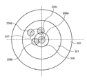
以下、ファイバ結合装置100の動作について説明する。図3に示すように、ウェッジ板102に入射する光の光軸200を回転中心として、ウェッジ板102の回転角度を調整すると、ウェッジ板102から出射される光の進行方向が変化する。
102 ウェッジ板
103 回転駆動部
104 集光レンズ
107 光ファイバ
200 光軸
300 コア
301 第1クラッド
302 第2クラッド
Claims (2)
- 入射した光を所定方向に屈折させるウェッジ板と、
前記ウェッジ板を通過した光を集光させる集光レンズと、
前記集光レンズで集光された光が入射する入射端面と、前記入射端面の中心を含む位置に設けられたコアと、前記コアの外周側に設けられた第1クラッドと、前記第1クラッドの外周側に設けられた第2クラッドとを有する光ファイバとを備え、
前記ウェッジ板は、前記ウェッジ板に入射する光の光軸を回転中心として回転可能に保持されており、入射面に対して出射面が傾斜しており、
前記ウェッジ板の回転角度に応じて、前記ウェッジ板を通過し前記集光レンズで集光され前記入射端面に入射する光の入射位置及び入射角度が連続的に変化し、
前記ウェッジ板は、前記コア及び前記第1クラッドの少なくとも一方に光が入射するように、その回転角度が調整可能に保持されており、前記コアへの入射光のエネルギーと前記第1クラッドへの入射光のエネルギーの比率を、可変とし、
前記ウェッジ板が第1の回転角度に位置付けられた場合、前記ウェッジ板を通過した光は、前記集光レンズの中心と前記光ファイバの前記入射端面の中心とを通過し、
前記ウェッジ板が前記第1の回転角度とは異なる第2の回転角度に位置付けられた場合、前記ウェッジ板を通過し前記集光レンズで集光された光は、前記第1クラッドのみに入射することを特徴とするファイバ結合装置。 - 前記光軸を回転中心として前記ウェッジ板を回転させる回転駆動部をさらに備えることを特徴とする請求項1に記載のファイバ結合装置。
Applications Claiming Priority (3)
| Application Number | Priority Date | Filing Date | Title |
|---|---|---|---|
| JP2016240056 | 2016-12-12 | ||
| JP2016240056 | 2016-12-12 | ||
| PCT/JP2017/033804 WO2018110016A1 (ja) | 2016-12-12 | 2017-09-20 | ファイバ結合装置 |
Publications (2)
| Publication Number | Publication Date |
|---|---|
| JPWO2018110016A1 JPWO2018110016A1 (ja) | 2019-10-24 |
| JP6970877B2 true JP6970877B2 (ja) | 2021-11-24 |
Family
ID=62558295
Family Applications (1)
| Application Number | Title | Priority Date | Filing Date |
|---|---|---|---|
| JP2018556189A Active JP6970877B2 (ja) | 2016-12-12 | 2017-09-20 | ファイバ結合装置 |
Country Status (6)
| Country | Link |
|---|---|
| US (1) | US10955618B2 (ja) |
| EP (1) | EP3553575B1 (ja) |
| JP (1) | JP6970877B2 (ja) |
| CN (1) | CN110036320B (ja) |
| PL (1) | PL3553575T3 (ja) |
| WO (1) | WO2018110016A1 (ja) |
Families Citing this family (7)
| Publication number | Priority date | Publication date | Assignee | Title |
|---|---|---|---|---|
| EP3978183B1 (en) | 2019-05-29 | 2024-03-06 | Panasonic Intellectual Property Management Co., Ltd. | Laser machining device and laser machining method using same |
| EP3978181A4 (en) | 2019-05-29 | 2022-08-03 | Panasonic Intellectual Property Management Co., Ltd. | Laser machining device and laser machining method using same |
| JP7347286B2 (ja) * | 2020-03-24 | 2023-09-20 | 株式会社島津製作所 | ファイバ結合モジュール |
| CN113649690A (zh) * | 2020-05-12 | 2021-11-16 | 深圳市联赢激光股份有限公司 | 一种具有圆形和环形光斑切变功能的光学系统 |
| WO2022013144A1 (en) * | 2020-07-14 | 2022-01-20 | El.En. S.P.A. | A laser equipment with a laser source and a beam deflector |
| EP4330744A4 (en) * | 2021-04-29 | 2025-03-26 | Ram Photonics Ind Llc | METHOD AND SYSTEM FOR ALIGNING AND SPLICING POLARIZATION MAINTAINING FIBER |
| JP7585987B2 (ja) | 2021-06-14 | 2024-11-19 | 株式会社島津製作所 | 光源装置、加工装置、および検査方法 |
Family Cites Families (16)
| Publication number | Priority date | Publication date | Assignee | Title |
|---|---|---|---|---|
| IT1170643B (it) * | 1981-01-22 | 1987-06-03 | Selenia Ind Elettroniche | Dispositivo perfezionato per l'accoppiamento di un fascio laser ad una fibra ottica |
| US4997250A (en) * | 1989-11-17 | 1991-03-05 | General Electric Company | Fiber output coupler with beam shaping optics for laser materials processing system |
| JPH04318819A (ja) * | 1991-04-18 | 1992-11-10 | Pioneer Electron Corp | 光波長変換装置 |
| JPH05157930A (ja) | 1991-11-13 | 1993-06-25 | Furukawa Electric Co Ltd:The | 光ロータリジョイント |
| US5245682A (en) | 1992-09-25 | 1993-09-14 | General Electric Company | Fiber optic delivered beam quality control system for power lasers |
| JPH09292544A (ja) * | 1996-04-23 | 1997-11-11 | Ando Electric Co Ltd | 光コリメータ結合器 |
| JP2002023072A (ja) * | 2000-07-06 | 2002-01-23 | Mitsubishi Electric Corp | 光スイッチ及びその調整方法並びに組み立て方法 |
| CN101065915B (zh) * | 2004-08-05 | 2012-12-05 | Jds尤尼弗思公司 | 具有电压感应光学吸收的光学马赫-曾德调制器的偏压控制方法和设备 |
| US7944567B2 (en) * | 2005-12-05 | 2011-05-17 | Fujifilm Corporation | Semiconductor light emitting element, light source using the semiconductor light emitting element, and optical tomography imaging apparatus |
| JP2007173649A (ja) * | 2005-12-23 | 2007-07-05 | Toshiba Corp | ファイバレーザ装置、光学機構及び入射方法 |
| US7983313B2 (en) * | 2009-01-30 | 2011-07-19 | Northrop Grumman Information Technology, Inc. | System and method for coupling multiple beams to an active fiber |
| DE102010003750A1 (de) | 2010-04-08 | 2011-10-13 | Trumpf Laser- Und Systemtechnik Gmbh | Verfahren und Anordnung zum Verändern der Strahlprofilcharakteristik eines Laserstrahls mittels einer Mehrfachclad-Faser |
| JP6244308B2 (ja) * | 2011-12-09 | 2017-12-06 | ルーメンタム オペレーションズ エルエルシーLumentum Operations LLC | レーザービームのビームパラメータ積を変動させること |
| WO2013181183A1 (en) * | 2012-05-30 | 2013-12-05 | Ipg Photonics Corporation | High power spatial filter |
| US9110246B2 (en) * | 2013-05-29 | 2015-08-18 | Ipg Photonics Corporation | High power spatial filter |
| US9696485B2 (en) * | 2014-07-16 | 2017-07-04 | Oplink Communications, Llc | Optical circulator array |
-
2017
- 2017-09-20 WO PCT/JP2017/033804 patent/WO2018110016A1/ja active Application Filing
- 2017-09-20 EP EP17879762.7A patent/EP3553575B1/en active Active
- 2017-09-20 CN CN201780075099.3A patent/CN110036320B/zh active Active
- 2017-09-20 PL PL17879762T patent/PL3553575T3/pl unknown
- 2017-09-20 JP JP2018556189A patent/JP6970877B2/ja active Active
-
2019
- 2019-05-30 US US16/426,699 patent/US10955618B2/en active Active
Also Published As
| Publication number | Publication date |
|---|---|
| US10955618B2 (en) | 2021-03-23 |
| EP3553575B1 (en) | 2022-01-26 |
| CN110036320A (zh) | 2019-07-19 |
| PL3553575T3 (pl) | 2022-05-30 |
| EP3553575A4 (en) | 2019-12-04 |
| CN110036320B (zh) | 2020-10-30 |
| WO2018110016A1 (ja) | 2018-06-21 |
| EP3553575A1 (en) | 2019-10-16 |
| US20190278026A1 (en) | 2019-09-12 |
| JPWO2018110016A1 (ja) | 2019-10-24 |
Similar Documents
| Publication | Publication Date | Title |
|---|---|---|
| JP6970877B2 (ja) | ファイバ結合装置 | |
| JP4386137B2 (ja) | レーザ加工装置及びレーザ加工方法 | |
| US8835804B2 (en) | Beam homogenizer | |
| JP5941113B2 (ja) | 集光径を拡大できるレーザ加工装置 | |
| TWI444745B (zh) | 光路切換裝置及光信號之光路切換方法 | |
| KR20050074653A (ko) | 광 섬유 또는 도파로 렌즈 | |
| CN107646093A (zh) | 用于借助于激光辐射加工材料的装置 | |
| JPH11326832A (ja) | 偏光ビ―ム装置 | |
| US10926358B2 (en) | Drilling device, method, and use | |
| JP2012017231A (ja) | レーザ光によるガラス基板加工装置 | |
| JP2016524723A (ja) | Tir光ファイバレンズを形成する方法 | |
| JP2008134468A (ja) | 集光光学系および光加工装置 | |
| JP4736633B2 (ja) | レーザ照射装置 | |
| CN217571287U (zh) | 一种用于激光切割的贝塞尔光束镜头 | |
| CN113296188B (zh) | 光子集成芯片上的轨道角动量滤波器实现方法 | |
| CN103534631A (zh) | 激光束辐照度控制系统 | |
| JP2004133040A (ja) | 光結合装置 | |
| CN103430062B (zh) | 光纤及其制造方法 | |
| JP2003340588A (ja) | 透明材料内部の処理方法およびその装置 | |
| CN113305426A (zh) | 一种用于激光切割的贝塞尔光束镜头 | |
| JPH01191801A (ja) | 集光レンズ | |
| KR102780320B1 (ko) | 초단 레이저 펄스를 이용해서 재료를 가공하기 위한 시스템 | |
| JPH1197340A (ja) | 露光光学系、光加工装置、露光装置及び光結合装置 | |
| CN114226959A (zh) | 激光加工系统及互补锥形镜组 | |
| JPS63108318A (ja) | レ−ザ−加工装置 |
Legal Events
| Date | Code | Title | Description |
|---|---|---|---|
| A521 | Request for written amendment filed |
Free format text: JAPANESE INTERMEDIATE CODE: A523 Effective date: 20190425 |
|
| A621 | Written request for application examination |
Free format text: JAPANESE INTERMEDIATE CODE: A621 Effective date: 20200316 |
|
| A131 | Notification of reasons for refusal |
Free format text: JAPANESE INTERMEDIATE CODE: A131 Effective date: 20201027 |
|
| A521 | Request for written amendment filed |
Free format text: JAPANESE INTERMEDIATE CODE: A523 Effective date: 20201210 |
|
| A131 | Notification of reasons for refusal |
Free format text: JAPANESE INTERMEDIATE CODE: A131 Effective date: 20210406 |
|
| A521 | Request for written amendment filed |
Free format text: JAPANESE INTERMEDIATE CODE: A523 Effective date: 20210415 |
|
| TRDD | Decision of grant or rejection written | ||
| A01 | Written decision to grant a patent or to grant a registration (utility model) |
Free format text: JAPANESE INTERMEDIATE CODE: A01 Effective date: 20210914 |
|
| A61 | First payment of annual fees (during grant procedure) |
Free format text: JAPANESE INTERMEDIATE CODE: A61 Effective date: 20210927 |
|
| R151 | Written notification of patent or utility model registration |
Ref document number: 6970877 Country of ref document: JP Free format text: JAPANESE INTERMEDIATE CODE: R151 |