EP3553575A1 - Fiber coupling device - Google Patents
Fiber coupling device Download PDFInfo
- Publication number
- EP3553575A1 EP3553575A1 EP17879762.7A EP17879762A EP3553575A1 EP 3553575 A1 EP3553575 A1 EP 3553575A1 EP 17879762 A EP17879762 A EP 17879762A EP 3553575 A1 EP3553575 A1 EP 3553575A1
- Authority
- EP
- European Patent Office
- Prior art keywords
- wedge plate
- light
- incident
- optical fiber
- condenser lens
- Prior art date
- Legal status (The legal status is an assumption and is not a legal conclusion. Google has not performed a legal analysis and makes no representation as to the accuracy of the status listed.)
- Granted
Links
- 239000000835 fiber Substances 0.000 title claims abstract description 30
- 230000008878 coupling Effects 0.000 title claims abstract description 26
- 238000010168 coupling process Methods 0.000 title claims abstract description 26
- 238000005859 coupling reaction Methods 0.000 title claims abstract description 26
- 239000013307 optical fiber Substances 0.000 claims abstract description 63
- 230000003287 optical effect Effects 0.000 claims abstract description 25
- 238000009826 distribution Methods 0.000 description 10
- 230000000694 effects Effects 0.000 description 6
- 238000000034 method Methods 0.000 description 3
- 238000006073 displacement reaction Methods 0.000 description 2
- 208000025174 PANDAS Diseases 0.000 description 1
- 208000021155 Paediatric autoimmune neuropsychiatric disorders associated with streptococcal infection Diseases 0.000 description 1
- 240000000220 Panda oleosa Species 0.000 description 1
- 235000016496 Panda oleosa Nutrition 0.000 description 1
- VYPSYNLAJGMNEJ-UHFFFAOYSA-N Silicium dioxide Chemical compound O=[Si]=O VYPSYNLAJGMNEJ-UHFFFAOYSA-N 0.000 description 1
- 238000010521 absorption reaction Methods 0.000 description 1
- 238000000149 argon plasma sintering Methods 0.000 description 1
- 230000008021 deposition Effects 0.000 description 1
- 230000006866 deterioration Effects 0.000 description 1
- 239000000428 dust Substances 0.000 description 1
- 239000005350 fused silica glass Substances 0.000 description 1
- 230000010287 polarization Effects 0.000 description 1
- 230000000644 propagated effect Effects 0.000 description 1
- 230000001902 propagating effect Effects 0.000 description 1
Images


Classifications
-
- G—PHYSICS
- G02—OPTICS
- G02B—OPTICAL ELEMENTS, SYSTEMS OR APPARATUS
- G02B27/00—Optical systems or apparatus not provided for by any of the groups G02B1/00 - G02B26/00, G02B30/00
- G02B27/09—Beam shaping, e.g. changing the cross-sectional area, not otherwise provided for
- G02B27/0938—Using specific optical elements
- G02B27/0994—Fibers, light pipes
-
- G—PHYSICS
- G02—OPTICS
- G02B—OPTICAL ELEMENTS, SYSTEMS OR APPARATUS
- G02B6/00—Light guides; Structural details of arrangements comprising light guides and other optical elements, e.g. couplings
- G02B6/24—Coupling light guides
- G02B6/26—Optical coupling means
- G02B6/32—Optical coupling means having lens focusing means positioned between opposed fibre ends
-
- G—PHYSICS
- G02—OPTICS
- G02B—OPTICAL ELEMENTS, SYSTEMS OR APPARATUS
- G02B19/00—Condensers, e.g. light collectors or similar non-imaging optics
- G02B19/0004—Condensers, e.g. light collectors or similar non-imaging optics characterised by the optical means employed
- G02B19/0028—Condensers, e.g. light collectors or similar non-imaging optics characterised by the optical means employed refractive and reflective surfaces, e.g. non-imaging catadioptric systems
-
- G—PHYSICS
- G02—OPTICS
- G02B—OPTICAL ELEMENTS, SYSTEMS OR APPARATUS
- G02B26/00—Optical devices or arrangements for the control of light using movable or deformable optical elements
- G02B26/08—Optical devices or arrangements for the control of light using movable or deformable optical elements for controlling the direction of light
- G02B26/0875—Optical devices or arrangements for the control of light using movable or deformable optical elements for controlling the direction of light by means of one or more refracting elements
- G02B26/0883—Optical devices or arrangements for the control of light using movable or deformable optical elements for controlling the direction of light by means of one or more refracting elements the refracting element being a prism
- G02B26/0891—Optical devices or arrangements for the control of light using movable or deformable optical elements for controlling the direction of light by means of one or more refracting elements the refracting element being a prism forming an optical wedge
-
- G—PHYSICS
- G02—OPTICS
- G02B—OPTICAL ELEMENTS, SYSTEMS OR APPARATUS
- G02B27/00—Optical systems or apparatus not provided for by any of the groups G02B1/00 - G02B26/00, G02B30/00
- G02B27/09—Beam shaping, e.g. changing the cross-sectional area, not otherwise provided for
- G02B27/0927—Systems for changing the beam intensity distribution, e.g. Gaussian to top-hat
-
- G—PHYSICS
- G02—OPTICS
- G02B—OPTICAL ELEMENTS, SYSTEMS OR APPARATUS
- G02B27/00—Optical systems or apparatus not provided for by any of the groups G02B1/00 - G02B26/00, G02B30/00
- G02B27/09—Beam shaping, e.g. changing the cross-sectional area, not otherwise provided for
- G02B27/0938—Using specific optical elements
- G02B27/095—Refractive optical elements
- G02B27/0955—Lenses
-
- G—PHYSICS
- G02—OPTICS
- G02B—OPTICAL ELEMENTS, SYSTEMS OR APPARATUS
- G02B6/00—Light guides; Structural details of arrangements comprising light guides and other optical elements, e.g. couplings
- G02B6/24—Coupling light guides
- G02B6/26—Optical coupling means
- G02B6/262—Optical details of coupling light into, or out of, or between fibre ends, e.g. special fibre end shapes or associated optical elements
-
- G—PHYSICS
- G02—OPTICS
- G02B—OPTICAL ELEMENTS, SYSTEMS OR APPARATUS
- G02B6/00—Light guides; Structural details of arrangements comprising light guides and other optical elements, e.g. couplings
- G02B6/24—Coupling light guides
- G02B6/36—Mechanical coupling means
- G02B6/3616—Holders, macro size fixtures for mechanically holding or positioning fibres, e.g. on an optical bench
- G02B6/3624—Fibre head, e.g. fibre probe termination
-
- G—PHYSICS
- G02—OPTICS
- G02B—OPTICAL ELEMENTS, SYSTEMS OR APPARATUS
- G02B6/00—Light guides; Structural details of arrangements comprising light guides and other optical elements, e.g. couplings
- G02B6/02—Optical fibres with cladding with or without a coating
- G02B6/036—Optical fibres with cladding with or without a coating core or cladding comprising multiple layers
- G02B6/03616—Optical fibres characterised both by the number of different refractive index layers around the central core segment, i.e. around the innermost high index core layer, and their relative refractive index difference
- G02B6/03622—Optical fibres characterised both by the number of different refractive index layers around the central core segment, i.e. around the innermost high index core layer, and their relative refractive index difference having 2 layers only
- G02B6/03633—Optical fibres characterised both by the number of different refractive index layers around the central core segment, i.e. around the innermost high index core layer, and their relative refractive index difference having 2 layers only arranged - -
-
- G—PHYSICS
- G02—OPTICS
- G02B—OPTICAL ELEMENTS, SYSTEMS OR APPARATUS
- G02B6/00—Light guides; Structural details of arrangements comprising light guides and other optical elements, e.g. couplings
- G02B6/24—Coupling light guides
- G02B6/42—Coupling light guides with opto-electronic elements
- G02B6/4201—Packages, e.g. shape, construction, internal or external details
- G02B6/4204—Packages, e.g. shape, construction, internal or external details the coupling comprising intermediate optical elements, e.g. lenses, holograms
- G02B6/4206—Optical features
-
- G—PHYSICS
- G02—OPTICS
- G02B—OPTICAL ELEMENTS, SYSTEMS OR APPARATUS
- G02B6/00—Light guides; Structural details of arrangements comprising light guides and other optical elements, e.g. couplings
- G02B6/24—Coupling light guides
- G02B6/42—Coupling light guides with opto-electronic elements
- G02B6/4296—Coupling light guides with opto-electronic elements coupling with sources of high radiant energy, e.g. high power lasers, high temperature light sources
Definitions
- the present invention relates to a fiber coupling device for enabling laser light to be collected and received by an optical fiber.
- Patent Literature 1 There has been a known technique for performing various kinds of processing using the same power source by propagating high-power laser light to an optical fiber and by changing properties of the light emitted from the optical fiber (e.g., Patent Literature 1).
- Patent literature 1 shows a technique for changing the propagation conditions of laser light in an optical fiber by using a plurality of condenser lenses with different focal lengths.
- the condenser lens placed in the optical path of the laser light is made replaceable. This makes the focal length of the condenser lens in the optical path variable, thereby making the numerical aperture (NA) of the light incident on the optical fiber variable.
- NA numerical aperture
- Such conventional fiber coupling devices can change properties of the emitted light discretely but not continuously.
- an object of the present invention is to provide a fiber coupling device capable of continuously changing properties of light emitted from the optical fiber.
- the fiber coupling device of the present invention includes a wedge plate for receiving light and refracting the light in a predetermined direction; a condenser lens for collecting the light refracted by the wedge plate; and an optical fiber having an incident surface for receiving the light collected by the condenser lens.
- the wedge plate is held rotatable around the optical axis of the light incident on the wedge plate. The light refracted by the wedge plate and collected by the condenser lens is incident on a different point on the incident surface depending on the rotation angle of the wedge plate.
- a simple rotation of the wedge plate can change properties of light emitted from the optical fiber, without the need to stop the output of the laser light when the condenser lens is replaced.
- the coordinate axes (X, Y, and Z axes) shown in the drawings are orthogonal to each other.
- the Y axis corresponds to the vertical direction of the plane of the drawings.
- laser output device 101 emits, as collimated light, high-power laser light with a predetermined beam size.
- the collimated light enters fiber coupling device 100.
- laser output device 101 outputs multimode near-infrared laser light with a wavelength of 1 ⁇ m and an output of 4 kW.
- the beam size is 3 mm.
- the chain line shown in FIG. 1 represents optical axis 200 of the laser light emitted from device 101, whereas the two-dot chain lines represent optical path 201 of the laser light.
- Fiber coupling device 100 includes the following components: wedge plate 102 for receiving light and refracting the light in a predetermined direction; rotary drive unit 103 for rotating wedge plate 102 around optical axis 200 of the light incident on wedge plate 102; condenser lens 104 for collecting the light refracted by wedge plate 102; and optical fiber 107 having an incident surface for receiving the light collected by condenser lens 104.
- Wedge plate 102 which is a circular disk-shaped optical member, has an emission surface inclined with respect to the incident surface. Hence, wedge plate 102 can refract incident light in a predetermined direction. Wedge plate 102 is held in cylindrical member 110, which is surrounded by an unillustrated gear.
- Rotary drive unit 103 which is formed of a small motor, has drive shaft 111 with gear 112 in mesh with the gear of cylindrical member 110.
- Rotary drive unit 103 rotates gear 112 to transmit a rotational driving force to cylindrical member 110. This allows wedge plate 102 to rotate around optical axis 200 of the light incident on wedge plate 102.
- the rotation angle of wedge plate 102 can be adjusted by adjusting the rotation angle of gear 112.
- Gear 112 can be replaced by an unillustrated belt for transmitting the rotational driving force of rotary drive unit 103 to cylindrical member 110.
- Condenser lens 104 can have a focal length of 20 to 50 mm. Lens 104 is optically designed so that the multimode laser light used can have a spot diameter of about 80 ⁇ m and that the NA is less than 0.2 when the laser light is collected.
- Condenser lens 104 is held in adjustment holding unit 105 so as to be fixed in position without distortion.
- Unit 105 fixes condenser lens 104, which is a high-precision part, so as to prevent the incident surface of optical fiber 107 from being damaged by the displacement of the point of light collection.
- optical fiber 107 concentrically has two waveguides for transmitting two beams of light, respectively.
- optical fiber 107 is a double-clad fiber having the following: core 300 including the center of the incident surface; first clad 301 outside core 300, and second clad 302 outside first clad 301 ( FIG. 3 ).
- first clad 301 and second clad 302 of optical fiber 107 have refractive indexes of nc, n1, and n2, respectively, these indexes are in the relation of nc > n1 > n2.
- core 300 has a diameter of 100 ⁇ m and an NA of 0.2
- first clad 301 has an outer diameter of 400 ⁇ m and an NA of 0.4.
- Optical fiber 107 is held in position by receptacle 106 so as to prevent displacement of the incident point. Unlike the illustrated configuration, if optical fiber 107 has an inlet facing down in the vertical direction (the negative direction along the Y axis), dust deposition may be prevented.
- the light which has propagated through optical fiber 107 by fiber coupling device 100, is emitted as light 202.
- Wedge plate 102 can be, for example, a plate coated with an anti-reflection (AR) film and with low loss.
- AR anti-reflection
- One example is a plate made of fused silica and having a refractive index nw of 1.45.
- the declination "a" of wedge plate 102 can be expressed by the following formula (1) when sin ( ⁇ w) ⁇ 1. a ⁇ nw ⁇ 1 ⁇ ⁇ w where when the wedge angle ⁇ w is set to 2 degrees, the declination "a" of the emitted light can be set to 1 degree.
- the center of condenser lens 104 and the center of the incident surface of optical fiber 107 are concentrically arranged.
- optical axis 200 is aligned with the center of condenser lens 104 and with the central axis of optical fiber 107.
- wedge plate 102 is referred to as being at a reference rotation position.
- the first rotation angle is referred to as the reference rotation position.
- the light collected by condenser lens 104 is incident on core 300 of optical fiber 107 when wedge plate 102 is at the reference rotation position.
- the light incident on core 300 has a spot diameter smaller than the diameter of core 300.
- High-power laser light when passing through wedge plate 102, has a thermal lens effect on plate 102.
- wedge plate 102 is not replaced. Therefore, if the output of the laser light is kept constant, the lens properties of wedge plate 102 caused by the thermal lens effect remain unchanged, or in other words, wedge plate 102 has a constant focal length.
- the optical design can be made in consideration of the thermal lens effect at any output, preventing deterioration of the coupling efficiency of the laser light to optical fiber 107.
- the laser light always passes through the center of wedge plate 102, thereby reducing light scattering and absorption losses outside the effective diameter.
- wedge angle ⁇ w of wedge plate 102 and the declination "a" with respect to the optical axis given by wedge plate 102 are in the above-mentioned relation of Formula (1). Hence, similar effects can be obtained by selecting an appropriate wedge plate according to the wavelength, output and beam quality of the light to be used.
- fiber coupling device 100 The operation of fiber coupling device 100 will be described as follows. As shown in FIG. 3 , adjusting the rotation angle of wedge plate 102 around optical axis 200 of the light incident on wedge plate 102 can change the direction of travel of the light emitted from wedge plate 102.
- optical path 204 forms a cone with a vertical angle 2a around optical axis 200.
- the direction of travel of the light incident on condenser lens 104 is changed depending on the rotation angle of wedge plate 102.
- This changes causes a change in the point on the incident surface of optical fiber 107 which the light is incident after being refracted by wedge plate 102 and being collected by condenser lens 104.
- wedge plate 102 is at a different rotation angle, the light is incident on a different point on the incident surface of optical fiber 107.
- FIG. 4 shows wedge plate 102 rotated 180 degrees from the reference rotation position. This position is referred to as the inverted position.
- the inverted position is a second rotation angle different from the first rotation angle.
- FIG. 4 includes optical path 205 formed when wedge plate 102 is at the inverted position.
- FIG. 4 also includes, for comparison, optical path 204 formed when wedge plate 102 is at the reference rotation position.
- optical path 205 in the inverted position is changed.
- This inversion changes both the point and angle of incidence of the light refracted by wedge plate 102 with respect to condenser lens 104.
- the light refracted by wedge plate 102 is incident on condenser lens 104 at its upper part (the positive side of the Y axis).
- the angle of incidence to condenser lens 104 can be expressed by 90 - 2a [°].
- the focal point of the light collected by condenser lens 104 changes across the incident surface of optical fiber 107 in such a manner as to move along chain line 207.
- the collected light can have a focal point which changes continuously as focal points 208a, 208b, 208d and 208c in this order.
- wedge plate 102 When the laser light is at focal point 208a, wedge plate 102 is at the reference rotation position or the first rotation angle, so that the laser light is collected and received by core 300 only.
- the laser light is mostly collected and received by core 300, but is partly collected and received by first clad 301.
- the laser light straddles core 300 and first clad 301.
- two or more clad propagation modes exist.
- wedge plate 102 When the laser light is at focal point 208d, wedge plate 102 is at the inverted position or the second rotation angle, so that the laser light is collected and received by first clad 301 only.
- the laser light is mostly collected and received by first clad 301, but is partly collected and received by core 300.
- the laser light straddles core 300 and first clad 301.
- two or more clad propagation modes exist.
- the distance from the point 208a to the point 208d can be made greater than 140 ⁇ m. This allows choosing whether the laser light should be collected and received by either core 300 only by first clad 301 only.
- wedge plate 102 can be designed to rotate in such a manner as to change the point of light collection on optical fiber 107 along chain line 207.
- the point and angle of incidence of the laser light with respect to optical fiber 107 can be selected continuously so that the energy of the laser light incident on core 300 and first clad 301 can be variable.
- the ratio of the energy of the light incident on core 300 to the energy of the light incident on first clad 301 can be variable.
- the energy of the incident light can be selectively distributed between core 300 and first clad 301, thereby changing the light propagation mode in optical fiber 107.
- FIG. 6 (a) shows intensity distributions 209a, 209b, 209c and 209d of the emitted light corresponding to focal points 208a, 208b, 208c and 208d ( FIG. 5 ), respectively.
- the vertical axis represents the energy E of the light emitted from optical fiber 107, whereas the horizontal axis represents the distance r from the center of core 300.
- FIG. 6 (b) shows the refractive index distribution of optical fiber 107.
- the vertical axis represents the refractive index n of the waveguide, whereas the horizontal axis represents the distance r from the center of core 300.
- the broken lines represent the boundary surfaces between core 300 and first clad 301 and between first clad 301 and second clad 302 in optical fiber 107.
- the NA of the emitted light is small.
- the NA increases in the order of 209b, 209c and 209d along with the rotation of wedge plate 102.
- the energy from first clad 301 is greater than the energy from core 300. This indicates that the emitted light has a doughnut-shaped intensity distribution with low intensity at the beam center.
- a comparison between the intensity distributions 209b and 209c of the emitted light corresponding to the focal points 208b and 208c, respectively, indicates as follows. As the proportion of the energy that enters core 300 of optical fiber 107 is smaller, the intensity distribution is more similar in shape to a top hat.
- the light is incident on a different point on the incident surface of optical fiber 107 along with a change in the rotation angle of wedge plate 102. Therefore, adjusting the rotation angle of wedge plate 102 can change the light propagation conditions in optical fiber 107. Furthermore, the propagation conditions can be changed without stopping the output of the laser light. This enables continuously changing properties of the light emitted from optical fiber 107.
- the light propagation mode in optical fiber 107 changes, thereby continuously changing properties of the light emitted from optical fiber 107.
- the light can have a doughnut-shaped intensity distribution with low intensity at the beam center. This enables the light emitted from optical fiber 107 to be applied to a wide range by reducing its density. Thus, laser light with low precision of positioning can be used for a large laser process surface.
- wedge plate 102 can be rotated such that the light can straddle core 300 and first clad 301 instead of striking core 300 only or first clad 301 only on the incident surface of optical fiber 107.
- Optical fiber 107 used in the present exemplary embodiment is a double-clad fiber, but it may alternatively be, for example, a PANDA fiber or a double-core fiber. Using these fibers can achieve polarization control or a special beam called a ring beam.
- the laser light as the light source is multimode near-infrared collimated light in the present exemplary embodiment, but it may alternatively be laser light with different wavelengths or in a single mode.
- the propagation mode does not matter.
- Fiber coupling device 100 of the present exemplary embodiment includes rotary drive unit 103 for rotating wedge plate 102.
- the rotary drive unit is not an indispensable component; wedge plate 102 can only be rotated around the optical axis of the incident light.
- wedge plate 102 is at a different rotation angle, the light is incident on a different point on the incident surface of optical fiber 107. This enables changing properties of the light emitted from optical fiber 107 continuously depending on the rotation angle of wedge plate 102.
- the present invention which can continuously change properties of laser light emitted from an optical fiber, is useful as a fiber coupling device for making the laser light collected and received by the optical fiber.
Abstract
Description
- The present invention relates to a fiber coupling device for enabling laser light to be collected and received by an optical fiber.
- There has been a known technique for performing various kinds of processing using the same power source by propagating high-power laser light to an optical fiber and by changing properties of the light emitted from the optical fiber (e.g., Patent Literature 1).
- Patent literature 1 shows a technique for changing the propagation conditions of laser light in an optical fiber by using a plurality of condenser lenses with different focal lengths. To be more specific, the condenser lens placed in the optical path of the laser light is made replaceable. This makes the focal length of the condenser lens in the optical path variable, thereby making the numerical aperture (NA) of the light incident on the optical fiber variable. Thus, switching between the different condenser lenses can change the beam quality of the laser light emitted from the optical fiber.
- PTL 1:
US Patent No. 5245682 - Such conventional fiber coupling devices can change properties of the emitted light discretely but not continuously.
- This is because when the condenser lens in the laser light path is replaced, the output of the laser light should be stopped until the replacement is completed. If the condenser lens were replaced without stopping the output of the laser light, the light scattered outside the effective diameter of the condenser lens might generate heat, or the laser light might fail to be collected at a desired point.
- In view of the above problems, an object of the present invention is to provide a fiber coupling device capable of continuously changing properties of light emitted from the optical fiber.
- The fiber coupling device of the present invention includes a wedge plate for receiving light and refracting the light in a predetermined direction; a condenser lens for collecting the light refracted by the wedge plate; and an optical fiber having an incident surface for receiving the light collected by the condenser lens. The wedge plate is held rotatable around the optical axis of the light incident on the wedge plate. The light refracted by the wedge plate and collected by the condenser lens is incident on a different point on the incident surface depending on the rotation angle of the wedge plate.
- According to the present invention, a simple rotation of the wedge plate can change properties of light emitted from the optical fiber, without the need to stop the output of the laser light when the condenser lens is replaced.
-
-
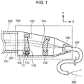
FIG. 1 is a partially cutaway side view of a fiber coupling device according to a present exemplary embodiment. -
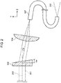
FIG. 2 is a partially cutaway side view showing the placement of a wedge plate, a condenser lens, and an optical fiber. -
FIG. 3 is a partially cutaway perspective view showing changes in the optical paths due to changes in the rotation angle of the wedge plate. -
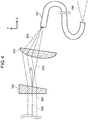
FIG. 4 is a partially cutaway side view corresponding to the view ofFIG. 2 when the rotation angle of the wedge plate is changed. -
FIG. 5 is a front view of the incident surface of the optical fiber. -
FIG. 6 shows the intensity distribution of light emitted from the optical fiber and the refractive index distribution of the optical fiber. - The exemplary embodiment of the present invention will be described as follows with reference to drawings. In these drawings, the same reference numerals are used for the same components and the description thereof may be omitted.
- The coordinate axes (X, Y, and Z axes) shown in the drawings are orthogonal to each other. The Y axis corresponds to the vertical direction of the plane of the drawings.
- As shown in
FIG. 1 ,laser output device 101 emits, as collimated light, high-power laser light with a predetermined beam size. The collimated light entersfiber coupling device 100. - In the present exemplary embodiment,
laser output device 101 outputs multimode near-infrared laser light with a wavelength of 1 µm and an output of 4 kW. The beam size is 3 mm. The chain line shown inFIG. 1 representsoptical axis 200 of the laser light emitted fromdevice 101, whereas the two-dot chain lines representoptical path 201 of the laser light. -
Fiber coupling device 100 includes the following components:wedge plate 102 for receiving light and refracting the light in a predetermined direction;rotary drive unit 103 for rotatingwedge plate 102 aroundoptical axis 200 of the light incident onwedge plate 102;condenser lens 104 for collecting the light refracted bywedge plate 102; andoptical fiber 107 having an incident surface for receiving the light collected bycondenser lens 104. -
Wedge plate 102, which is a circular disk-shaped optical member, has an emission surface inclined with respect to the incident surface. Hence,wedge plate 102 can refract incident light in a predetermined direction. Wedgeplate 102 is held incylindrical member 110, which is surrounded by an unillustrated gear. -
Rotary drive unit 103, which is formed of a small motor, has driveshaft 111 withgear 112 in mesh with the gear ofcylindrical member 110.Rotary drive unit 103 rotatesgear 112 to transmit a rotational driving force tocylindrical member 110. This allowswedge plate 102 to rotate aroundoptical axis 200 of the light incident onwedge plate 102. The rotation angle ofwedge plate 102 can be adjusted by adjusting the rotation angle ofgear 112. - Gear 112 can be replaced by an unillustrated belt for transmitting the rotational driving force of
rotary drive unit 103 tocylindrical member 110. -
Condenser lens 104 can have a focal length of 20 to 50 mm.Lens 104 is optically designed so that the multimode laser light used can have a spot diameter of about 80 µm and that the NA is less than 0.2 when the laser light is collected. -
Condenser lens 104 is held inadjustment holding unit 105 so as to be fixed in position without distortion.Unit 105fixes condenser lens 104, which is a high-precision part, so as to prevent the incident surface ofoptical fiber 107 from being damaged by the displacement of the point of light collection. -
Optical fiber 107 concentrically has two waveguides for transmitting two beams of light, respectively. To be more specific,optical fiber 107 is a double-clad fiber having the following:core 300 including the center of the incident surface;first clad 301 outsidecore 300, andsecond clad 302 outside first clad 301 (FIG. 3 ). - When
core 300,first clad 301 andsecond clad 302 ofoptical fiber 107 have refractive indexes of nc, n1, and n2, respectively, these indexes are in the relation of nc > n1 > n2. In the present exemplary embodiment,core 300 has a diameter of 100 µm and an NA of 0.2, whereasfirst clad 301 has an outer diameter of 400 µm and an NA of 0.4. -
Optical fiber 107 is held in position byreceptacle 106 so as to prevent displacement of the incident point. Unlike the illustrated configuration, ifoptical fiber 107 has an inlet facing down in the vertical direction (the negative direction along the Y axis), dust deposition may be prevented. - The light, which has propagated through
optical fiber 107 byfiber coupling device 100, is emitted as light 202. - As shown in
FIG. 2 , whenwedge plate 102 is at a predetermined first rotation angle, the light refracted bywedge plate 102 passes through the center ofcondenser lens 104 and the center of the incident surface ofoptical fiber 107. - To be more specific, the light entered
fiber coupling device 100 in the direction parallel to the Z axis is given a declination "a" bywedge plate 102.Wedge plate 102 can be, for example, a plate coated with an anti-reflection (AR) film and with low loss. One example is a plate made of fused silica and having a refractive index nw of 1.45. - Assuming that the wedge angle is θw, the declination "a" of
wedge plate 102 can be expressed by the following formula (1) when sin (θw) << 1.
- As shown in
FIG. 2 , the center ofcondenser lens 104 and the center of the incident surface ofoptical fiber 107 are concentrically arranged. In addition,optical axis 200 is aligned with the center ofcondenser lens 104 and with the central axis ofoptical fiber 107. In this case,wedge plate 102 is referred to as being at a reference rotation position. In short, the first rotation angle is referred to as the reference rotation position. The light collected bycondenser lens 104 is incident oncore 300 ofoptical fiber 107 whenwedge plate 102 is at the reference rotation position. The light incident oncore 300 has a spot diameter smaller than the diameter ofcore 300. - The following is a description of effects obtained when laser light passes through
fiber coupling device 100. As shown inFIGS. 1 and2 , whenwedge plate 102 is at the reference rotation position, the laser light emitted fromdevice 101 is refracted as collimated light bywedge plate 102, passes through the center ofcondenser lens 104, and is collected and received bycore 300 ofoptical fiber 107. - High-power laser light, when passing through
wedge plate 102, has a thermal lens effect onplate 102. However, infiber coupling device 100 of the present exemplary embodiment,wedge plate 102 is not replaced. Therefore, if the output of the laser light is kept constant, the lens properties ofwedge plate 102 caused by the thermal lens effect remain unchanged, or in other words,wedge plate 102 has a constant focal length. - Thus, the optical design can be made in consideration of the thermal lens effect at any output, preventing deterioration of the coupling efficiency of the laser light to
optical fiber 107. - The laser light always passes through the center of
wedge plate 102, thereby reducing light scattering and absorption losses outside the effective diameter. - The wedge angle θw of
wedge plate 102 and the declination "a" with respect to the optical axis given bywedge plate 102 are in the above-mentioned relation of Formula (1). Hence, similar effects can be obtained by selecting an appropriate wedge plate according to the wavelength, output and beam quality of the light to be used. - The operation of
fiber coupling device 100 will be described as follows. As shown inFIG. 3 , adjusting the rotation angle ofwedge plate 102 aroundoptical axis 200 of the light incident onwedge plate 102 can change the direction of travel of the light emitted fromwedge plate 102. - The light refracted by
wedge plate 102 is given the declination "a" with respect tooptical axis 200 of the light incident onwedge plate 102. As a result, aswedge plate 102 rotates,optical path 204 forms a cone with a vertical angle 2a aroundoptical axis 200. - In other words, the direction of travel of the light incident on
condenser lens 104 is changed depending on the rotation angle ofwedge plate 102. This changes causes a change in the point on the incident surface ofoptical fiber 107 which the light is incident after being refracted bywedge plate 102 and being collected bycondenser lens 104. Thus, whenwedge plate 102 is at a different rotation angle, the light is incident on a different point on the incident surface ofoptical fiber 107. -
FIG. 4 showswedge plate 102 rotated 180 degrees from the reference rotation position. This position is referred to as the inverted position. The inverted position is a second rotation angle different from the first rotation angle.FIG. 4 includesoptical path 205 formed whenwedge plate 102 is at the inverted position.FIG. 4 also includes, for comparison,optical path 204 formed whenwedge plate 102 is at the reference rotation position. - As shown in
FIG. 4 , whenwedge plate 102 is at the reference rotation position, the light refracted bywedge plate 102 is incident oncondenser lens 104 in the direction perpendicular to the center oflens 104 as shown byoptical path 204. The light collected bycondenser lens 104 is incident ononly core 300 ofoptical fiber 107. In other words, whenwedge plate 102 is at the first rotation angle, the light is incident ononly core 300 ofoptical fiber 107. - Meanwhile, when
wedge plate 102 is inverted from the reference rotation position,optical path 205 in the inverted position is changed. This inversion changes both the point and angle of incidence of the light refracted bywedge plate 102 with respect tocondenser lens 104. To be more specific, the light refracted bywedge plate 102 is incident oncondenser lens 104 at its upper part (the positive side of the Y axis). In this case, the angle of incidence tocondenser lens 104 can be expressed by 90 - 2a [°]. - As shown in
FIG. 3 and4 , whenwedge plate 102 is at the inverted position, the light collected bycondenser lens 104 is not incident oncore 300 ofoptical fiber 107, but incident on first clad 301 only. Thus, whenwedge plate 102 is at the second rotation angle, the light is incident on only first clad 301 ofoptical fiber 107. Subsequently, light 206 is emitted fromoptical fiber 107 in a different mode fromlight 202, which is emitted whenwedge plate 102 is at the reference rotation position. - As shown in
FIG. 5 , aswedge plate 102 rotates, the focal point of the light collected bycondenser lens 104 changes across the incident surface ofoptical fiber 107 in such a manner as to move alongchain line 207. Thus, the collected light can have a focal point which changes continuously asfocal points - When the laser light is at
focal point 208a,wedge plate 102 is at the reference rotation position or the first rotation angle, so that the laser light is collected and received bycore 300 only. - At
focal point 208b, the laser light is mostly collected and received bycore 300, but is partly collected and received by first clad 301. In other words, atfocal point 208b, the laser light straddlescore 300 and first clad 301. As a result, two or more clad propagation modes exist. - When the laser light is at
focal point 208d,wedge plate 102 is at the inverted position or the second rotation angle, so that the laser light is collected and received by first clad 301 only. - At
focal point 208c, the laser light is mostly collected and received by first clad 301, but is partly collected and received bycore 300. In other words, atfocal point 208c, the laser light straddlescore 300 and first clad 301. As a result, two or more clad propagation modes exist. - Assuming that the laser light has a spot diameter of 80 µm, the distance from the
point 208a to thepoint 208d can be made greater than 140 µm. This allows choosing whether the laser light should be collected and received by eithercore 300 only by first clad 301 only. - Thus,
wedge plate 102 can be designed to rotate in such a manner as to change the point of light collection onoptical fiber 107 alongchain line 207. In this case, the point and angle of incidence of the laser light with respect tooptical fiber 107 can be selected continuously so that the energy of the laser light incident oncore 300 and first clad 301 can be variable. In short, the ratio of the energy of the light incident oncore 300 to the energy of the light incident on first clad 301 can be variable. - As a result, the energy of the incident light can be selectively distributed between
core 300 and first clad 301, thereby changing the light propagation mode inoptical fiber 107. - The following is a description of changes in the light propagation mode in
optical fiber 107. -
FIG. 6 (a) showsintensity distributions focal points FIG. 5 ), respectively. The vertical axis represents the energy E of the light emitted fromoptical fiber 107, whereas the horizontal axis represents the distance r from the center ofcore 300. -
FIG. 6 (b) shows the refractive index distribution ofoptical fiber 107. The vertical axis represents the refractive index n of the waveguide, whereas the horizontal axis represents the distance r from the center ofcore 300. The broken lines represent the boundary surfaces betweencore 300 and first clad 301 and between first clad 301 and second clad 302 inoptical fiber 107. - In the
intensity distribution 209a corresponding to thefocal point 208a, the NA of the emitted light is small. The NA increases in the order of 209b, 209c and 209d along with the rotation ofwedge plate 102. - In the
intensity distribution 209d corresponding to thefocal point 208d, the energy from first clad 301 is greater than the energy fromcore 300. This indicates that the emitted light has a doughnut-shaped intensity distribution with low intensity at the beam center. - A comparison between the
intensity distributions focal points core 300 ofoptical fiber 107 is smaller, the intensity distribution is more similar in shape to a top hat. - As described above, according to
fiber coupling device 100 of the present exemplary embodiment, the light is incident on a different point on the incident surface ofoptical fiber 107 along with a change in the rotation angle ofwedge plate 102. Therefore, adjusting the rotation angle ofwedge plate 102 can change the light propagation conditions inoptical fiber 107. Furthermore, the propagation conditions can be changed without stopping the output of the laser light. This enables continuously changing properties of the light emitted fromoptical fiber 107. - When
wedge plate 102 is at the reference rotation position (the first rotation angle), the light refracted bywedge plate 102 passes through the center ofcondenser lens 104 and the center of the incident surface ofoptical fiber 107. Thus, whenwedge plate 102 is at the reference rotation position, the light is incident on the center ofcondenser lens 104. When the rotation angle ofwedge plate 102 is changed, the light is incident on a point oncondenser lens 104 different from the center. - This can change the point and angle of incidence of the light onto the incident surface of
optical fiber 107, thereby changing the ratio of the energy that propagates throughcore 300 to the energy that propagates through first clad 301 inoptical fiber 107. As a result, the light propagation mode inoptical fiber 107 changes, thereby continuously changing properties of the light emitted fromoptical fiber 107. - When
wedge plate 102 is rotated, for example, to the opposite position (the second rotation angle) so that the laser light is incident on first clad 301 only, the light can have a doughnut-shaped intensity distribution with low intensity at the beam center. This enables the light emitted fromoptical fiber 107 to be applied to a wide range by reducing its density. Thus, laser light with low precision of positioning can be used for a large laser process surface. - Furthermore,
wedge plate 102 can be rotated such that the light can straddlecore 300 and first clad 301 instead of strikingcore 300 only or first clad 301 only on the incident surface ofoptical fiber 107. -
Optical fiber 107 used in the present exemplary embodiment is a double-clad fiber, but it may alternatively be, for example, a PANDA fiber or a double-core fiber. Using these fibers can achieve polarization control or a special beam called a ring beam. - The laser light as the light source is multimode near-infrared collimated light in the present exemplary embodiment, but it may alternatively be laser light with different wavelengths or in a single mode. The propagation mode does not matter.
-
Fiber coupling device 100 of the present exemplary embodiment includesrotary drive unit 103 for rotatingwedge plate 102. In the present invention, however, the rotary drive unit is not an indispensable component;wedge plate 102 can only be rotated around the optical axis of the incident light. Whenwedge plate 102 is at a different rotation angle, the light is incident on a different point on the incident surface ofoptical fiber 107. This enables changing properties of the light emitted fromoptical fiber 107 continuously depending on the rotation angle ofwedge plate 102. - As described above, the present invention, which can continuously change properties of laser light emitted from an optical fiber, is useful as a fiber coupling device for making the laser light collected and received by the optical fiber.
-
- 100
- fiber coupling device
- 102
- wedge plate
- 103
- rotary drive unit
- 104
- condenser lens
- 107
- optical fiber
- 200
- optical axis
- 300
- core
- 301
- first clad
- 302
- second clad
Claims (5)
- A fiber coupling device comprising:a wedge plate configured to receive light and to refract the light in a predetermined direction;a condenser lens configured to collect the light refracted by the wedge plate; andan optical fiber having an incident surface configured to receive the light collected by the condenser lens;the wedge plate being held rotatable around an optical axis of the light incident on the wedge plate,the light refracted by the wedge plate and collected by the condenser lens striking a different point on the incident surface depending on a rotation angle of the wedge plate.
- The fiber coupling device according to claim 1, wherein
the optical fiber comprises:a core including a center of the incident surface;a first clad outside the core; anda second clad outside the first clad, andthe rotation angle of the wedge plate is adjustable such that the light is incident on at least one of the core and the first clad. - The fiber coupling device according to claim 2, wherein when the wedge plate is at a first rotation angle, the light refracted by the wedge plate passes through a center of the condenser lens and the center of the incident surface of the optical fiber.
- The fiber coupling device according to claim 3, wherein when the wedge plate is at a second rotation angle different from the first rotation angle, the light refracted by the wedge plate and collected by the condenser lens is incident on the first clad only.
- The fiber coupling device according to any one of claims 1 to 4, further comprising a rotary drive unit configured to rotate the wedge plate around the optical axis of the light incident on the wedge plate.
Priority Applications (1)
| Application Number | Priority Date | Filing Date | Title |
|---|---|---|---|
| PL17879762T PL3553575T3 (en) | 2016-12-12 | 2017-09-20 | Fiber coupling device |
Applications Claiming Priority (2)
| Application Number | Priority Date | Filing Date | Title |
|---|---|---|---|
| JP2016240056 | 2016-12-12 | ||
| PCT/JP2017/033804 WO2018110016A1 (en) | 2016-12-12 | 2017-09-20 | Fiber coupling device |
Publications (3)
| Publication Number | Publication Date |
|---|---|
| EP3553575A1 true EP3553575A1 (en) | 2019-10-16 |
| EP3553575A4 EP3553575A4 (en) | 2019-12-04 |
| EP3553575B1 EP3553575B1 (en) | 2022-01-26 |
Family
ID=62558295
Family Applications (1)
| Application Number | Title | Priority Date | Filing Date |
|---|---|---|---|
| EP17879762.7A Active EP3553575B1 (en) | 2016-12-12 | 2017-09-20 | Fiber coupling device |
Country Status (6)
| Country | Link |
|---|---|
| US (1) | US10955618B2 (en) |
| EP (1) | EP3553575B1 (en) |
| JP (1) | JP6970877B2 (en) |
| CN (1) | CN110036320B (en) |
| PL (1) | PL3553575T3 (en) |
| WO (1) | WO2018110016A1 (en) |
Families Citing this family (3)
| Publication number | Priority date | Publication date | Assignee | Title |
|---|---|---|---|---|
| JP7347286B2 (en) * | 2020-03-24 | 2023-09-20 | 株式会社島津製作所 | fiber coupling module |
| CN113649690A (en) * | 2020-05-12 | 2021-11-16 | 深圳市联赢激光股份有限公司 | Optical system with circular and annular light spot cutting function |
| WO2022013144A1 (en) * | 2020-07-14 | 2022-01-20 | El.En. S.P.A. | A laser equipment with a laser source and a beam deflector |
Family Cites Families (16)
| Publication number | Priority date | Publication date | Assignee | Title |
|---|---|---|---|---|
| IT1170643B (en) * | 1981-01-22 | 1987-06-03 | Selenia Ind Elettroniche | IMPROVED DEVICE FOR COUPLING A LASER BEAM TO AN OPTICAL FIBER |
| US4997250A (en) * | 1989-11-17 | 1991-03-05 | General Electric Company | Fiber output coupler with beam shaping optics for laser materials processing system |
| JPH04318819A (en) * | 1991-04-18 | 1992-11-10 | Pioneer Electron Corp | Light-wavelength conversion device |
| JPH05157930A (en) | 1991-11-13 | 1993-06-25 | Furukawa Electric Co Ltd:The | Optical rotary joint |
| US5245682A (en) | 1992-09-25 | 1993-09-14 | General Electric Company | Fiber optic delivered beam quality control system for power lasers |
| JPH09292544A (en) * | 1996-04-23 | 1997-11-11 | Ando Electric Co Ltd | Optical collimator coupler |
| JP2002023072A (en) * | 2000-07-06 | 2002-01-23 | Mitsubishi Electric Corp | Optical switch, control method therefor and assembly method |
| EP1776608B1 (en) * | 2004-08-05 | 2018-10-24 | Lumentum Operations LLC | Bias-control for optical mach-zehnder modulators with voltage-induced optical absorption |
| US7944567B2 (en) * | 2005-12-05 | 2011-05-17 | Fujifilm Corporation | Semiconductor light emitting element, light source using the semiconductor light emitting element, and optical tomography imaging apparatus |
| JP2007173649A (en) * | 2005-12-23 | 2007-07-05 | Toshiba Corp | Fiber laser device, optical mechanism and incidence method |
| US7983313B2 (en) * | 2009-01-30 | 2011-07-19 | Northrop Grumman Information Technology, Inc. | System and method for coupling multiple beams to an active fiber |
| DE102010003750A1 (en) * | 2010-04-08 | 2011-10-13 | Trumpf Laser- Und Systemtechnik Gmbh | Method and arrangement for changing the beam profile characteristic of a laser beam by means of a multiple-clad fiber |
| JP6244308B2 (en) * | 2011-12-09 | 2017-12-06 | ルーメンタム オペレーションズ エルエルシーLumentum Operations LLC | Varying the beam parameter product of the laser beam |
| EP3640691B1 (en) * | 2012-05-30 | 2023-09-20 | IPG Photonics Corporation | High power spatial filter |
| US9110246B2 (en) * | 2013-05-29 | 2015-08-18 | Ipg Photonics Corporation | High power spatial filter |
| US9696485B2 (en) * | 2014-07-16 | 2017-07-04 | Oplink Communications, Llc | Optical circulator array |
-
2017
- 2017-09-20 JP JP2018556189A patent/JP6970877B2/en active Active
- 2017-09-20 PL PL17879762T patent/PL3553575T3/en unknown
- 2017-09-20 CN CN201780075099.3A patent/CN110036320B/en active Active
- 2017-09-20 EP EP17879762.7A patent/EP3553575B1/en active Active
- 2017-09-20 WO PCT/JP2017/033804 patent/WO2018110016A1/en active Application Filing
-
2019
- 2019-05-30 US US16/426,699 patent/US10955618B2/en active Active
Also Published As
| Publication number | Publication date |
|---|---|
| EP3553575B1 (en) | 2022-01-26 |
| US10955618B2 (en) | 2021-03-23 |
| CN110036320A (en) | 2019-07-19 |
| CN110036320B (en) | 2020-10-30 |
| PL3553575T3 (en) | 2022-05-30 |
| WO2018110016A1 (en) | 2018-06-21 |
| EP3553575A4 (en) | 2019-12-04 |
| US20190278026A1 (en) | 2019-09-12 |
| JP6970877B2 (en) | 2021-11-24 |
| JPWO2018110016A1 (en) | 2019-10-24 |
Similar Documents
| Publication | Publication Date | Title |
|---|---|---|
| US10955618B2 (en) | Fiber coupling device | |
| US7228032B2 (en) | Apparatus and methods for launching an optical signal into multimode optical fiber | |
| US7920763B1 (en) | Mode field expanded fiber collimator | |
| CN103728696B (en) | A kind of 1 �� N fiber coupler | |
| CN107111085B (en) | It is insulated optical coupling system | |
| RU2204155C2 (en) | Optical insulator | |
| JP5134028B2 (en) | Optical parts | |
| JP2000206359A (en) | Optical fiber coupling device | |
| EP3239749B1 (en) | Photo coupler and method for optically coupling grin lens-attached optical fibers | |
| JP2016524723A (en) | Method for forming a TIR optical fiber lens | |
| CN113296188B (en) | Method for realizing orbital angular momentum filter on photonic integrated chip | |
| JP2001242357A (en) | Optical semiconductor device | |
| CN104981722A (en) | Single beam splitter transmission-type pohotonic crystal fiber resonant cavity | |
| Hillerich et al. | Deterioration of taper lens performance due to taper asymmetry | |
| US20020114568A1 (en) | Optical fiber termination collimator and process of manufacture | |
| CN103534631A (en) | Laser beam irradiance control systems | |
| CN212905744U (en) | Laser coupling to single mode fiber angle deviation adjusting module applied to automatic machine | |
| JP6540310B2 (en) | Fiber optic terminal | |
| CN113305426A (en) | Bessel beam lens for laser cutting | |
| JP2008151897A (en) | Optical demultiplexer | |
| JP6596744B2 (en) | Optical element | |
| CN217571287U (en) | Bessel beam lens for laser cutting | |
| US20070036485A1 (en) | Optical fiber device | |
| KR101567985B1 (en) | optical fiber having dual core and laser machining apparatus using the same | |
| Madsen | Multiport optical concentrator for multimode fibers and high-speed detector interfacing |
Legal Events
| Date | Code | Title | Description |
|---|---|---|---|
| STAA | Information on the status of an ep patent application or granted ep patent |
Free format text: STATUS: THE INTERNATIONAL PUBLICATION HAS BEEN MADE |
|
| PUAI | Public reference made under article 153(3) epc to a published international application that has entered the european phase |
Free format text: ORIGINAL CODE: 0009012 |
|
| STAA | Information on the status of an ep patent application or granted ep patent |
Free format text: STATUS: REQUEST FOR EXAMINATION WAS MADE |
|
| 17P | Request for examination filed |
Effective date: 20190429 |
|
| AK | Designated contracting states |
Kind code of ref document: A1 Designated state(s): AL AT BE BG CH CY CZ DE DK EE ES FI FR GB GR HR HU IE IS IT LI LT LU LV MC MK MT NL NO PL PT RO RS SE SI SK SM TR |
|
| AX | Request for extension of the european patent |
Extension state: BA ME |
|
| A4 | Supplementary search report drawn up and despatched |
Effective date: 20191106 |
|
| RIC1 | Information provided on ipc code assigned before grant |
Ipc: G02B 6/036 20060101ALN20191030BHEP Ipc: B23K 26/073 20060101ALI20191030BHEP Ipc: G02B 6/42 20060101AFI20191030BHEP Ipc: B23K 26/064 20140101ALI20191030BHEP |
|
| DAV | Request for validation of the european patent (deleted) | ||
| DAX | Request for extension of the european patent (deleted) | ||
| REG | Reference to a national code |
Ref country code: DE Ref legal event code: R079 Ref document number: 602017052918 Country of ref document: DE Free format text: PREVIOUS MAIN CLASS: G02B0006320000 Ipc: G02B0006420000 |
|
| GRAP | Despatch of communication of intention to grant a patent |
Free format text: ORIGINAL CODE: EPIDOSNIGR1 |
|
| STAA | Information on the status of an ep patent application or granted ep patent |
Free format text: STATUS: GRANT OF PATENT IS INTENDED |
|
| RIC1 | Information provided on ipc code assigned before grant |
Ipc: G02B 6/036 20060101ALN20210917BHEP Ipc: G02B 27/09 20060101ALI20210917BHEP Ipc: G02B 26/08 20060101ALI20210917BHEP Ipc: G02B 6/36 20060101ALI20210917BHEP Ipc: G02B 6/42 20060101AFI20210917BHEP |
|
| INTG | Intention to grant announced |
Effective date: 20211007 |
|
| GRAS | Grant fee paid |
Free format text: ORIGINAL CODE: EPIDOSNIGR3 |
|
| GRAA | (expected) grant |
Free format text: ORIGINAL CODE: 0009210 |
|
| STAA | Information on the status of an ep patent application or granted ep patent |
Free format text: STATUS: THE PATENT HAS BEEN GRANTED |
|
| AK | Designated contracting states |
Kind code of ref document: B1 Designated state(s): AL AT BE BG CH CY CZ DE DK EE ES FI FR GB GR HR HU IE IS IT LI LT LU LV MC MK MT NL NO PL PT RO RS SE SI SK SM TR |
|
| REG | Reference to a national code |
Ref country code: GB Ref legal event code: FG4D |
|
| REG | Reference to a national code |
Ref country code: CH Ref legal event code: EP |
|
| REG | Reference to a national code |
Ref country code: AT Ref legal event code: REF Ref document number: 1465731 Country of ref document: AT Kind code of ref document: T Effective date: 20220215 |
|
| REG | Reference to a national code |
Ref country code: IE Ref legal event code: FG4D |
|
| REG | Reference to a national code |
Ref country code: DE Ref legal event code: R096 Ref document number: 602017052918 Country of ref document: DE |
|
| REG | Reference to a national code |
Ref country code: LT Ref legal event code: MG9D |
|
| REG | Reference to a national code |
Ref country code: NL Ref legal event code: MP Effective date: 20220126 |
|
| REG | Reference to a national code |
Ref country code: AT Ref legal event code: MK05 Ref document number: 1465731 Country of ref document: AT Kind code of ref document: T Effective date: 20220126 |
|
| PG25 | Lapsed in a contracting state [announced via postgrant information from national office to epo] |
Ref country code: NL Free format text: LAPSE BECAUSE OF FAILURE TO SUBMIT A TRANSLATION OF THE DESCRIPTION OR TO PAY THE FEE WITHIN THE PRESCRIBED TIME-LIMIT Effective date: 20220126 |
|
| PG25 | Lapsed in a contracting state [announced via postgrant information from national office to epo] |
Ref country code: SE Free format text: LAPSE BECAUSE OF FAILURE TO SUBMIT A TRANSLATION OF THE DESCRIPTION OR TO PAY THE FEE WITHIN THE PRESCRIBED TIME-LIMIT Effective date: 20220126 Ref country code: RS Free format text: LAPSE BECAUSE OF FAILURE TO SUBMIT A TRANSLATION OF THE DESCRIPTION OR TO PAY THE FEE WITHIN THE PRESCRIBED TIME-LIMIT Effective date: 20220126 Ref country code: PT Free format text: LAPSE BECAUSE OF FAILURE TO SUBMIT A TRANSLATION OF THE DESCRIPTION OR TO PAY THE FEE WITHIN THE PRESCRIBED TIME-LIMIT Effective date: 20220526 Ref country code: NO Free format text: LAPSE BECAUSE OF FAILURE TO SUBMIT A TRANSLATION OF THE DESCRIPTION OR TO PAY THE FEE WITHIN THE PRESCRIBED TIME-LIMIT Effective date: 20220426 Ref country code: LT Free format text: LAPSE BECAUSE OF FAILURE TO SUBMIT A TRANSLATION OF THE DESCRIPTION OR TO PAY THE FEE WITHIN THE PRESCRIBED TIME-LIMIT Effective date: 20220126 Ref country code: HR Free format text: LAPSE BECAUSE OF FAILURE TO SUBMIT A TRANSLATION OF THE DESCRIPTION OR TO PAY THE FEE WITHIN THE PRESCRIBED TIME-LIMIT Effective date: 20220126 Ref country code: ES Free format text: LAPSE BECAUSE OF FAILURE TO SUBMIT A TRANSLATION OF THE DESCRIPTION OR TO PAY THE FEE WITHIN THE PRESCRIBED TIME-LIMIT Effective date: 20220126 Ref country code: BG Free format text: LAPSE BECAUSE OF FAILURE TO SUBMIT A TRANSLATION OF THE DESCRIPTION OR TO PAY THE FEE WITHIN THE PRESCRIBED TIME-LIMIT Effective date: 20220426 |
|
| PG25 | Lapsed in a contracting state [announced via postgrant information from national office to epo] |
Ref country code: LV Free format text: LAPSE BECAUSE OF FAILURE TO SUBMIT A TRANSLATION OF THE DESCRIPTION OR TO PAY THE FEE WITHIN THE PRESCRIBED TIME-LIMIT Effective date: 20220126 Ref country code: GR Free format text: LAPSE BECAUSE OF FAILURE TO SUBMIT A TRANSLATION OF THE DESCRIPTION OR TO PAY THE FEE WITHIN THE PRESCRIBED TIME-LIMIT Effective date: 20220427 Ref country code: FI Free format text: LAPSE BECAUSE OF FAILURE TO SUBMIT A TRANSLATION OF THE DESCRIPTION OR TO PAY THE FEE WITHIN THE PRESCRIBED TIME-LIMIT Effective date: 20220126 Ref country code: AT Free format text: LAPSE BECAUSE OF FAILURE TO SUBMIT A TRANSLATION OF THE DESCRIPTION OR TO PAY THE FEE WITHIN THE PRESCRIBED TIME-LIMIT Effective date: 20220126 |
|
| PG25 | Lapsed in a contracting state [announced via postgrant information from national office to epo] |
Ref country code: IS Free format text: LAPSE BECAUSE OF FAILURE TO SUBMIT A TRANSLATION OF THE DESCRIPTION OR TO PAY THE FEE WITHIN THE PRESCRIBED TIME-LIMIT Effective date: 20220526 |
|
| REG | Reference to a national code |
Ref country code: DE Ref legal event code: R097 Ref document number: 602017052918 Country of ref document: DE |
|
| PG25 | Lapsed in a contracting state [announced via postgrant information from national office to epo] |
Ref country code: SM Free format text: LAPSE BECAUSE OF FAILURE TO SUBMIT A TRANSLATION OF THE DESCRIPTION OR TO PAY THE FEE WITHIN THE PRESCRIBED TIME-LIMIT Effective date: 20220126 Ref country code: SK Free format text: LAPSE BECAUSE OF FAILURE TO SUBMIT A TRANSLATION OF THE DESCRIPTION OR TO PAY THE FEE WITHIN THE PRESCRIBED TIME-LIMIT Effective date: 20220126 Ref country code: RO Free format text: LAPSE BECAUSE OF FAILURE TO SUBMIT A TRANSLATION OF THE DESCRIPTION OR TO PAY THE FEE WITHIN THE PRESCRIBED TIME-LIMIT Effective date: 20220126 Ref country code: EE Free format text: LAPSE BECAUSE OF FAILURE TO SUBMIT A TRANSLATION OF THE DESCRIPTION OR TO PAY THE FEE WITHIN THE PRESCRIBED TIME-LIMIT Effective date: 20220126 Ref country code: DK Free format text: LAPSE BECAUSE OF FAILURE TO SUBMIT A TRANSLATION OF THE DESCRIPTION OR TO PAY THE FEE WITHIN THE PRESCRIBED TIME-LIMIT Effective date: 20220126 Ref country code: CZ Free format text: LAPSE BECAUSE OF FAILURE TO SUBMIT A TRANSLATION OF THE DESCRIPTION OR TO PAY THE FEE WITHIN THE PRESCRIBED TIME-LIMIT Effective date: 20220126 |
|
| PG25 | Lapsed in a contracting state [announced via postgrant information from national office to epo] |
Ref country code: AL Free format text: LAPSE BECAUSE OF FAILURE TO SUBMIT A TRANSLATION OF THE DESCRIPTION OR TO PAY THE FEE WITHIN THE PRESCRIBED TIME-LIMIT Effective date: 20220126 |
|
| PLBE | No opposition filed within time limit |
Free format text: ORIGINAL CODE: 0009261 |
|
| STAA | Information on the status of an ep patent application or granted ep patent |
Free format text: STATUS: NO OPPOSITION FILED WITHIN TIME LIMIT |
|
| 26N | No opposition filed |
Effective date: 20221027 |
|
| PG25 | Lapsed in a contracting state [announced via postgrant information from national office to epo] |
Ref country code: SI Free format text: LAPSE BECAUSE OF FAILURE TO SUBMIT A TRANSLATION OF THE DESCRIPTION OR TO PAY THE FEE WITHIN THE PRESCRIBED TIME-LIMIT Effective date: 20220126 |
|
| PG25 | Lapsed in a contracting state [announced via postgrant information from national office to epo] |
Ref country code: MC Free format text: LAPSE BECAUSE OF FAILURE TO SUBMIT A TRANSLATION OF THE DESCRIPTION OR TO PAY THE FEE WITHIN THE PRESCRIBED TIME-LIMIT Effective date: 20220126 |
|
| REG | Reference to a national code |
Ref country code: CH Ref legal event code: PL |
|
| GBPC | Gb: european patent ceased through non-payment of renewal fee |
Effective date: 20220920 |
|
| REG | Reference to a national code |
Ref country code: BE Ref legal event code: MM Effective date: 20220930 |
|
| PG25 | Lapsed in a contracting state [announced via postgrant information from national office to epo] |
Ref country code: LU Free format text: LAPSE BECAUSE OF NON-PAYMENT OF DUE FEES Effective date: 20220920 |
|
| PG25 | Lapsed in a contracting state [announced via postgrant information from national office to epo] |
Ref country code: LI Free format text: LAPSE BECAUSE OF NON-PAYMENT OF DUE FEES Effective date: 20220930 Ref country code: IT Free format text: LAPSE BECAUSE OF FAILURE TO SUBMIT A TRANSLATION OF THE DESCRIPTION OR TO PAY THE FEE WITHIN THE PRESCRIBED TIME-LIMIT Effective date: 20220126 Ref country code: IE Free format text: LAPSE BECAUSE OF NON-PAYMENT OF DUE FEES Effective date: 20220920 Ref country code: CH Free format text: LAPSE BECAUSE OF NON-PAYMENT OF DUE FEES Effective date: 20220930 |
|
| PG25 | Lapsed in a contracting state [announced via postgrant information from national office to epo] |
Ref country code: BE Free format text: LAPSE BECAUSE OF NON-PAYMENT OF DUE FEES Effective date: 20220930 |
|
| PG25 | Lapsed in a contracting state [announced via postgrant information from national office to epo] |
Ref country code: GB Free format text: LAPSE BECAUSE OF NON-PAYMENT OF DUE FEES Effective date: 20220920 |
|
| PGFP | Annual fee paid to national office [announced via postgrant information from national office to epo] |
Ref country code: PL Payment date: 20230915 Year of fee payment: 7 Ref country code: FR Payment date: 20230928 Year of fee payment: 7 Ref country code: DE Payment date: 20230920 Year of fee payment: 7 |
|
| PG25 | Lapsed in a contracting state [announced via postgrant information from national office to epo] |
Ref country code: HU Free format text: LAPSE BECAUSE OF FAILURE TO SUBMIT A TRANSLATION OF THE DESCRIPTION OR TO PAY THE FEE WITHIN THE PRESCRIBED TIME-LIMIT; INVALID AB INITIO Effective date: 20170920 |
|
| PG25 | Lapsed in a contracting state [announced via postgrant information from national office to epo] |
Ref country code: CY Free format text: LAPSE BECAUSE OF FAILURE TO SUBMIT A TRANSLATION OF THE DESCRIPTION OR TO PAY THE FEE WITHIN THE PRESCRIBED TIME-LIMIT Effective date: 20220126 |