JP6944352B2 - Pachinko machine - Google Patents
Pachinko machine Download PDFInfo
- Publication number
- JP6944352B2 JP6944352B2 JP2017221889A JP2017221889A JP6944352B2 JP 6944352 B2 JP6944352 B2 JP 6944352B2 JP 2017221889 A JP2017221889 A JP 2017221889A JP 2017221889 A JP2017221889 A JP 2017221889A JP 6944352 B2 JP6944352 B2 JP 6944352B2
- Authority
- JP
- Japan
- Prior art keywords
- setting
- value
- display means
- display
- command
- Prior art date
- Legal status (The legal status is an assumption and is not a legal conclusion. Google has not performed a legal analysis and makes no representation as to the accuracy of the status listed.)
- Active
Links
- 238000000034 method Methods 0.000 claims description 376
- 230000008569 process Effects 0.000 claims description 365
- 238000012790 confirmation Methods 0.000 claims description 187
- 238000012545 processing Methods 0.000 claims description 168
- 230000005856 abnormality Effects 0.000 claims description 67
- 238000003860 storage Methods 0.000 claims description 33
- 230000005012 migration Effects 0.000 claims description 6
- 238000013508 migration Methods 0.000 claims description 6
- 230000008859 change Effects 0.000 description 381
- 230000000694 effects Effects 0.000 description 173
- 239000004973 liquid crystal related substance Substances 0.000 description 60
- 230000005540 biological transmission Effects 0.000 description 43
- 230000004397 blinking Effects 0.000 description 30
- 230000002159 abnormal effect Effects 0.000 description 28
- 238000005286 illumination Methods 0.000 description 28
- 230000006870 function Effects 0.000 description 24
- 238000011084 recovery Methods 0.000 description 20
- 238000009826 distribution Methods 0.000 description 15
- 230000003068 static effect Effects 0.000 description 15
- 230000002829 reductive effect Effects 0.000 description 13
- 239000002184 metal Substances 0.000 description 12
- 238000001514 detection method Methods 0.000 description 9
- 239000011521 glass Substances 0.000 description 9
- 238000004519 manufacturing process Methods 0.000 description 8
- 230000009471 action Effects 0.000 description 6
- 244000145845 chattering Species 0.000 description 6
- 230000017525 heat dissipation Effects 0.000 description 6
- 230000002265 prevention Effects 0.000 description 6
- 230000002776 aggregation Effects 0.000 description 5
- 238000004220 aggregation Methods 0.000 description 5
- 238000007689 inspection Methods 0.000 description 4
- 230000009191 jumping Effects 0.000 description 4
- 238000012986 modification Methods 0.000 description 4
- 230000004048 modification Effects 0.000 description 4
- 230000001186 cumulative effect Effects 0.000 description 3
- 230000007423 decrease Effects 0.000 description 3
- 230000003014 reinforcing effect Effects 0.000 description 3
- 238000004904 shortening Methods 0.000 description 3
- 230000007704 transition Effects 0.000 description 3
- 230000008901 benefit Effects 0.000 description 2
- 238000010586 diagram Methods 0.000 description 2
- 238000010304 firing Methods 0.000 description 2
- 230000036961 partial effect Effects 0.000 description 2
- 229920003002 synthetic resin Polymers 0.000 description 2
- 239000000057 synthetic resin Substances 0.000 description 2
- 241000287127 Passeridae Species 0.000 description 1
- 239000003086 colorant Substances 0.000 description 1
- 238000013461 design Methods 0.000 description 1
- 230000006872 improvement Effects 0.000 description 1
- 230000002452 interceptive effect Effects 0.000 description 1
- 230000009545 invasion Effects 0.000 description 1
- 230000000873 masking effect Effects 0.000 description 1
- 230000000149 penetrating effect Effects 0.000 description 1
- 230000002093 peripheral effect Effects 0.000 description 1
- 238000002360 preparation method Methods 0.000 description 1
- 238000003825 pressing Methods 0.000 description 1
- 230000002787 reinforcement Effects 0.000 description 1
- 229920005989 resin Polymers 0.000 description 1
- 239000011347 resin Substances 0.000 description 1
- 230000004044 response Effects 0.000 description 1
- 238000010187 selection method Methods 0.000 description 1
- 238000012546 transfer Methods 0.000 description 1
- 238000011144 upstream manufacturing Methods 0.000 description 1
- 125000000391 vinyl group Chemical group [H]C([*])=C([H])[H] 0.000 description 1
- 229920002554 vinyl polymer Polymers 0.000 description 1
- 230000000007 visual effect Effects 0.000 description 1
Images


Classifications
-
- Y—GENERAL TAGGING OF NEW TECHNOLOGICAL DEVELOPMENTS; GENERAL TAGGING OF CROSS-SECTIONAL TECHNOLOGIES SPANNING OVER SEVERAL SECTIONS OF THE IPC; TECHNICAL SUBJECTS COVERED BY FORMER USPC CROSS-REFERENCE ART COLLECTIONS [XRACs] AND DIGESTS
- Y02—TECHNOLOGIES OR APPLICATIONS FOR MITIGATION OR ADAPTATION AGAINST CLIMATE CHANGE
- Y02E—REDUCTION OF GREENHOUSE GAS [GHG] EMISSIONS, RELATED TO ENERGY GENERATION, TRANSMISSION OR DISTRIBUTION
- Y02E60/00—Enabling technologies; Technologies with a potential or indirect contribution to GHG emissions mitigation
- Y02E60/10—Energy storage using batteries
Landscapes
- Pinball Game Machines (AREA)
Description
本発明は、パチンコ機、アレンジボール機、スロットマシン等の遊技機に関するものである。 The present invention relates to gaming machines such as pachinko machines, arrange ball machines, and slot machines.
パチンコ機等の遊技機では、図柄始動手段に遊技球が入賞する等の所定条件が成立することに基づいて乱数抽選を行い、その乱数抽選で当選した場合に遊技者に有利な利益状態を発生させるように構成されている。例えばパチンコ機では、乱数抽選の当選確率(大当たり確率)が固定的に設定され、遊技盤の前側等のスペック表示部に表示されている(特許文献1)。 In a game machine such as a pachinko machine, a random number lottery is performed based on the condition that a game ball wins a prize in the symbol starting means, and when the random number lottery is won, a profit state advantageous to the player is generated. It is configured to let you. For example, in a pachinko machine, the winning probability (big hit probability) of a random number lottery is fixedly set and displayed on a spec display unit such as the front side of a game board (Patent Document 1).
このようにパチンコ機に関しては、乱数抽選の当選確率(大当たり確率)を任意に変更することは認められていなかったが、釘調整禁止の徹底等の流れにより、パチンコ機でもスロットマシンと同様に乱数抽選の当選確率に対応する設定値を任意に設定することが認められる方向にある。しかしながら、設定値の設定を可能にすると、その機能に関する処理の分だけプログラム容量が増加することとなり、限られたメモリ資源が圧迫されてしまうという問題がある。
本発明は上記事情に鑑みてなされたものであり、設定値の設定を可能にすることによるプログラム容量の増加を抑制することが可能な遊技機を提供することを目的とする。
In this way, regarding pachinko machines, it was not allowed to arbitrarily change the winning probability (big hit probability) of the random number lottery, but due to the flow of thorough prohibition of nail adjustment etc., random numbers are also used in pachinko machines as well as slot machines. There is a direction in which it is permitted to arbitrarily set a set value corresponding to the winning probability of the lottery. However, if the set value can be set, the program capacity is increased by the amount of processing related to the function, and there is a problem that limited memory resources are squeezed.
The present invention has been made in view of the above circumstances, and an object of the present invention is to provide a gaming machine capable of suppressing an increase in program capacity by making it possible to set a set value.
本発明は、電源投入時に電源投入処理を実行可能であり、電源投入後の遊技中に乱数抽選で当選した場合に遊技者に有利な特別遊技を実行可能な遊技機において、前記乱数抽選で当選する確率に関する設定値を記憶し、音量を調整操作可能な調整手段と、前記調整手段による調整内容を表示可能な表示手段と、第1記憶領域と、前記第1記憶領域とは異なる第2記憶領域と、遊技実績に基づいて算出される所定情報を表示可能な特定表示手段と、を備え、前記第1記憶領域に、遊技に関する情報を記憶し、前記第2記憶領域に、前記所定情報に関する情報を記憶し、前記電源投入処理を実行するためのプログラムは、前記設定値の設定が可能な設定可能期間中に前記設定値の設定を行うための設定値設定処理プログラムと、前記第1記憶領域をクリアするための第1記憶領域クリア処理プログラムと、前記設定値を確認するための設定確認処理プログラムと、バックアップから復帰させるためのバックアップ復帰処理プログラムと、前記バックアップ復帰処理プログラムに移行するためのバックアップ復帰移行処理プログラムとを含み、前記電源投入処理で前記設定確認処理プログラムを実行することなく前記バックアップ復帰処理プログラムを実行する場合には、前記バックアップ復帰移行処理プログラムから前記バックアップ復帰処理プログラムへと移行し、前記電源投入処理で前記設定確認処理プログラムと前記バックアップ復帰処理プログラムとを実行する場合には、前記設定確認処理プログラムから前記バックアップ復帰処理プログラムへと移行し、前記設定可能期間中に前記調整手段の操作が行われた場合、前記表示手段に前記調整内容を表示せず、当該設定可能期間中に行われた前記調整手段による調整が反映されないように構成し、前記特定表示手段は、確認表示を所定時間実行した後に、前記所定情報を表示可能であり、前記確認表示中に、前記第2記憶領域の異常チェック処理を実行可能に構成したものである。 INDUSTRIAL APPLICABILITY The present invention is a gaming machine capable of executing a power-on process when the power is turned on and capable of executing a special game advantageous to the player when the program is won by a random number lottery during the game after the power is turned on. An adjusting means capable of storing a set value related to the probability of a program and adjusting the volume, a display means capable of displaying the adjustment contents by the adjusting means, a first storage area, and a second storage different from the first storage area. An area and a specific display means capable of displaying predetermined information calculated based on a game record are provided, information about a game is stored in the first storage area, and information about the predetermined information is stored in the second storage area. The program for storing the information and executing the power-on process includes the set value setting process program for setting the set value during the settable period in which the set value can be set, and the first storage. To migrate to the first storage area clear processing program for clearing the area, the setting confirmation processing program for confirming the set value, the backup restoration processing program for restoring from the backup, and the backup restoration processing program. When the backup restoration processing program is executed without executing the setting confirmation processing program in the power-on processing, the backup restoration migration processing program is changed to the backup restoration processing program. When the setting confirmation processing program and the backup restoration processing program are executed in the power-on processing, the setting confirmation processing program is transferred to the backup restoration processing program, and during the settable period. When the operation of the adjusting means is performed, the adjustment content is not displayed on the display means, and the adjustment by the adjusting means made during the settable period is not reflected, and the specific display means is configured. The predetermined information can be displayed after the confirmation display is executed for a predetermined time, and the abnormality check process of the second storage area can be executed during the confirmation display .
本発明によれば、設定値の設定を可能にすることによるプログラム容量の増加を抑制することが可能である。 According to the present invention, it is possible to suppress an increase in the program capacity due to the ability to set a set value.
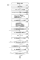
以下、発明の実施形態を図面に基づいて詳述する。図1〜図49は本発明をパチンコ機に採用した第1の実施形態を例示している。図1及び図2において、遊技機本体1は、外枠2と、この外枠2の前側に配置された前枠3とを備えている。前枠3は、左右方向一端側、例えば左端側に配置された上下方向の第1ヒンジ4を介して外枠2に開閉自在及び着脱自在に枢着されており、左右方向における第1ヒンジ4と反対側、例えば右端側に設けられた施錠手段5によって外枠2に対して閉状態で施錠可能となっている。
Hereinafter, embodiments of the invention will be described in detail with reference to the drawings. FIGS. 1 to 49 illustrate a first embodiment in which the present invention is applied to a pachinko machine. In FIGS. 1 and 2, the gaming machine
前枠3は、本体枠6と、その本体枠6の前側に配置されたガラス扉7とを備えている。ガラス扉7は、左右方向一端側、例えば左端側に配置された上下方向の第2ヒンジ8を介して本体枠6に開閉自在及び着脱自在に枢着されており、施錠手段5によって本体枠6に対して閉状態で施錠可能となっている。なお、第1ヒンジ4と第2ヒンジ8とは例えば同一軸心となるように配置されている。
The
外枠2は、図2に示すように左右一対の縦枠材2a,2bと上下一対の横枠材2c,2dとで矩形状に形成されている。外枠2の前側下部には、例えば合成樹脂製の前カバー部材9が、下横枠材2dの前縁に沿って左右の縦枠材2a,2bの前側下部を連結するように装着されている。前カバー部材9は、左右の縦枠材2a,2bよりも前側に突出しており、その上側に本体枠6が配置されている。また外枠2には、第1ヒンジ4を構成する外枠上ヒンジ金具11が例えば左上部に、同じく外枠下ヒンジ金具12が左下部における前カバー部材9の上側に夫々配置されている。
As shown in FIG. 2, the
本体枠6は合成樹脂製で、前カバー部材9の上側で外枠2の前縁側に略当接可能な矩形状の枠部13と、この枠部13内の上部側に設けられた遊技盤装着部14と、枠部13内の下部側に設けられた下部装着部15とを例えば一体に備えている。遊技盤装着部14には、遊技盤16が例えば前側から着脱自在に装着され、下部装着部15には、その前側に発射手段17、下部スピーカ18等が配置されている。また本体枠6には、第1ヒンジ4を構成する本体枠上ヒンジ金具19と第2ヒンジ8を構成する本体枠上ヒンジ金具20とが例えば左上部に、第1,第2ヒンジ4,8を構成する本体枠下ヒンジ金具21が例えば左下部に夫々配置されている。
The
ガラス扉7は、本体枠6の前面側に対応する矩形状に形成された樹脂製の扉ベース22を備えている。この扉ベース22には、遊技盤16に形成された遊技領域23の前側に対応してガラス窓24の窓孔24aが形成されると共に、例えば窓孔24aの周囲に複数(ここでは4つ)の上部スピーカ25、送風演出装置26等の演出手段が配置され、それら上部スピーカ25等を前側から略覆う上装飾カバー27が装着されている。
The
また扉ベース22の下部前側には、本体枠6の後側に配置された払い出し手段28から払い出された遊技球を貯留して発射手段17に供給する上皿30、その上皿30が満杯のときの余剰球等を貯留する下皿31、発射手段17を作動させるために操作する発射ハンドル32等が配置され、更に上皿30、下皿31等を前側から略覆う下装飾カバー33が装着されている。下装飾カバー33は、例えば前向きの膨出状に形成されており、例えばその上部側に、遊技者が押下操作可能な演出ボタン34、十字操作手段35等の所定操作手段が設けられている。
Further, on the lower front side of the
扉ベース22の背面側には、窓孔24aを後側から略塞ぐようにガラスユニット36が着脱自在に装着されると共に、第1,第2ヒンジ4,8側の縁部に沿って配置される上下方向のヒンジ端側補強板金37と、開閉端側の縁部に沿って配置される上下方向の開閉端側補強板金38と、窓孔24aの下側に配置される左右方向の下部補強板金39とがねじ止め等により着脱自在に固定されている。また扉ベース22には、第2ヒンジ8を構成するガラス扉上ヒンジ金具40が例えば左上部に、同じくガラス扉下ヒンジ金具41が例えば左下部に夫々配置されている。
A
また、例えば下部補強板金39の背面側には、球送りユニット42、下皿案内ユニット43等が装着されている。球送りユニット42は、上皿30内の遊技球を1個ずつ発射手段17に供給するためのもので、発射手段17の前側に対応して配置されている。下皿案内ユニット43は、上皿30が満杯となったときの余剰球、及び発射手段17により発射されたにも拘わらず遊技領域23に達することなく戻ってきたファール球を下皿31に案内するためのもので、例えば球送りユニット42に隣接してその第1,第2ヒンジ4,8側に配置されている。
Further, for example, a
また、本体枠6の例えば上部側には、前枠3が外枠2に対して開放しているか否かを検出可能な扉開放スイッチ44が設けられている。この扉開放スイッチ44は、例えば前枠3が外枠2に対して前側に開放したときにON、閉鎖したときにOFFとなるように構成されている。
Further, for example, on the upper side of the
遊技盤16は、図3に示すように例えばベニヤ板等のベース板45を備え、そのベース板45の前側に、発射手段17から発射された遊技球を案内するガイドレール46が環状に配置されると共に、そのガイドレール46の内側の遊技領域23に、中央表示枠ユニット47、始動入賞ユニット48、普通入賞ユニット49等のユニット部品の他、多数の遊技釘(図示省略)が配置され、また遊技領域23の外側の例えば下部側には遊技情報表示手段50が配置されている。
As shown in FIG. 3, the
遊技情報表示手段50は、図4に示すように、例えば8個のLED60で構成されるLEDグループを4つ備えており、それら計32個のLED60が普通図柄表示手段51、普通保留個数表示手段52、第1特別図柄表示手段53、第2特別図柄表示手段54、第1特別保留個数表示手段55、第2特別保留個数表示手段56、変動短縮報知手段57、右打ち報知手段58及びラウンド数報知手段59に所定個数ずつ割り当てられている。即ち、第1,第2LEDグループ50a,50bに属する各8個のLED60は夫々第1,第2特別図柄表示手段53,54を構成し、第3LEDグループ50cに属する8個のLED60は、2個ずつに分けられて夫々第1特別保留個数表示手段55、第2特別保留個数表示手段56、普通保留個数表示手段52、変動短縮報知手段57を構成し、第4LEDグループ50dに属する8個のLED60は、そのうちの2個が普通図柄表示手段51を、他の2個が右打ち報知手段58を、残りの4個がラウンド数報知手段59を夫々構成している。
As shown in FIG. 4, the game information display means 50 includes four LED groups composed of, for example, eight
遊技盤16の複数のユニット部品47〜49上には、普通図柄始動手段61、第1特別図柄始動手段62、第2特別図柄始動手段63、大入賞手段64、複数の普通入賞手段65等が設けられている。またベース板45の後側には、液晶表示手段(画像表示手段)66の他、液晶表示手段66の前側を移動可能な可動体67aを備えた可動演出手段67等が配置されている。
On the plurality of
中央表示枠ユニット47は、液晶表示手段66の表示枠を構成するもので、ベース板45に形成された前後方向貫通状の装着孔(図示省略)に対して前側から着脱自在に装着されている。この中央表示枠ユニット47は、図3に示すように、ベース板45の前面に沿って装着孔の外側に配置され且つその前側を遊技球が通過可能な前面装着板71と、液晶表示手段66の前側における左右両側から上部側にわたる正面視略門形状に配置され且つ前面装着板71の内周側で前向きに突設された装飾枠72と、その装飾枠72の左右の下端部間に配置されるステージ73とを備えている。発射手段17により発射され、遊技領域23の上部側に進入した遊技球は、装飾枠72の頂部で左右に振り分けられ、中央表示枠ユニット47の左側の左流下経路74aと右側の右流下経路74bとの何れかを流下する。
The central
中央表示枠ユニット47には、左流下経路74a側と右流下経路74b側との少なくとも一方側、例えば左流下経路74a側に、遊技球が流入可能なワープ入口75が設けられている。左流下経路74aを流下中にワープ入口75に流入した遊技球は、ステージ73上で左右方向に自由に転動した後、遊技領域23の左右方向中央に対応して設けられた中央落下部76とそれ以外の部分との何れかから前側に落下する。またステージ73の上側には、跳ね返り等による後側への遊技球の侵入を阻止するための侵入防止手段77が設けられている。
The central
始動入賞ユニット48は、中央表示枠ユニット47の下側に配置され、ベース板45に対して前側から着脱自在に装着されている。普通入賞ユニット49は、中央表示枠ユニット47の下側で始動入賞ユニット48の左側に配置され、ベース板45に対して前側から着脱自在に装着されている。
The
普通図柄始動手段61は、普通図柄表示手段51による普通図柄の変動表示を開始させるためのもので、遊技球が通過可能な通過ゲート等により構成され、遊技球の通過を検出する通過検出手段(図示省略)を備えている。この普通図柄始動手段61は、例えば中央表示枠ユニット47の右部における前面装着板71の前側に設けられており、右流下経路74bを流下する遊技球が通過可能となっている。
The normal symbol starting means 61 is for starting the variable display of the normal symbol by the normal symbol display means 51, and is composed of a passing gate or the like through which the game ball can pass, and is a passage detecting means (passing detecting means) for detecting the passage of the game ball. (Not shown). The ordinary symbol starting means 61 is provided, for example, on the front side of the front mounting
普通図柄表示手段51は、普通図柄を変動表示するためのもので、図4に示すように遊技情報表示手段50における例えば2個のLED60で構成されており、普通図柄始動手段61が遊技球を検出することに基づいて、普通図柄を構成するそれら2個のLED60が普通変動中発光パターンで発光した後、普通図柄始動手段61による遊技球検出時に取得された普通乱数情報に含まれる当たり判定乱数値が予め定められた当たり判定値と一致する場合には当たり態様(所定態様)で、それ以外の場合にははずれ態様で変動を停止する。なお、普通図柄を構成する2個のLED60は、それらの発光態様(例えば点灯/消灯)の組み合わせにより一又は複数の当たり態様と一又は複数のはずれ態様とを表示可能であり、また普通変動中発光パターンは、例えば特定の複数種類(ここでは2種類)の発光態様を所定時間(例えば128ms)毎に切り替えるようになっている。
The ordinary symbol display means 51 is for displaying the ordinary symbol in a variable manner, and is composed of, for example, two
また、普通図柄表示手段51の図柄変動中と普通利益状態中とを含む普通保留期間中に普通図柄始動手段61が遊技球を検出した場合には、それによって取得された普通乱数情報が予め定められた上限保留個数、例えば4個を限度として保留記憶され、普通保留期間が終了する毎に1個ずつ消化されて普通図柄の変動が行われる。普通乱数情報の記憶個数(普通保留個数)は、普通保留個数表示手段52等によって遊技者に報知される。普通保留個数表示手段52は、図4に示すように遊技情報表示手段50における例えば2個のLED60で構成されており、それら2個のLED60の夫々の発光態様(例えば点灯/点滅/消灯)の組み合わせにより、0〜4個の5種類の普通保留個数を表示可能となっている。
Further, when the ordinary symbol starting means 61 detects a game ball during the ordinary holding period including the symbol changing state and the ordinary profit state of the ordinary symbol displaying means 51, the ordinary random number information acquired by the detection is predetermined. The maximum number of reserved symbols, for example, 4 is reserved and stored, and each time the normal holding period ends, one is consumed and the normal symbol is changed. The stored number of ordinary random number information (ordinary hold number) is notified to the player by the ordinary hold number display means 52 or the like. As shown in FIG. 4, the normal hold number display means 52 is composed of, for example, two
第1特別図柄始動手段(図柄始動手段)62は、第1特別図柄表示手段53による図柄変動を開始させるためのもので、開閉手段を有しない非開閉式入賞手段により構成され、入賞した遊技球を検出する遊技球検出手段(図示省略)を備えている。この第1特別図柄始動手段62は、例えば始動入賞ユニット48に設けられ、ステージ73の中央落下部76に対応してその下側に上向き開口状に配置されており、左流下経路74a側のワープ入口75からステージ73を経て入賞するルートが存在すること等により、右流下経路74bを流下してきた遊技球よりも左流下経路74aを流下してきた遊技球の方が高い確率で入賞可能となっている。なお、この第1特別図柄始動手段62に遊技球が入賞すると、1入賞当たり所定個数の遊技球が賞球として払い出される。
The first special symbol starting means (symbol starting means) 62 is for starting the symbol variation by the first special symbol displaying means 53, and is composed of a non-opening / closing type winning means having no opening / closing means, and is a winning game ball. It is equipped with a game ball detecting means (not shown) for detecting. The first special symbol starting means 62 is provided in, for example, the
第2特別図柄始動手段(図柄始動手段)63は、第2特別図柄表示手段54による図柄変動を開始させるためのもので、開閉部78の作動によって遊技球が入賞可能な開状態と入賞不可能(又は開状態よりも入賞困難)な閉状態とに変化可能な開閉式入賞手段により構成され、入賞した遊技球を検出する遊技球検出手段(図示省略)を備えており、普通図柄表示手段51の変動後の停止図柄が当たり態様となって普通利益状態が発生したときに、開閉部78が所定時間閉状態から開状態に変化するようになっている。
The second special symbol starting means (symbol starting means) 63 is for starting the symbol variation by the second special symbol display means 54, and the game ball can be won in the open state and cannot be won by the operation of the opening / closing
この第2特別図柄始動手段63は、例えば中央表示枠ユニット47の右部における前面装着板71上で且つ普通図柄始動手段61の下流側に配置されており、右流下経路74bを流下してきた遊技球が入賞可能となっている。なお、開閉部78は例えば下部側に設けられた左右方向の回転軸廻りに揺動可能であり、閉状態では例えば前面装着板71と略面一となって遊技球が前側を通過可能となり、開状態では前面装着板71の前側で後ろ下がりの傾斜状となって遊技球を後向きに入賞させるようになっている。なお、この第2特別図柄始動手段63に遊技球が入賞すると、1入賞当たり所定個数の遊技球が賞球として払い出される。
The second special symbol starting means 63 is arranged, for example, on the
第1特別図柄表示手段(図柄表示手段)53は、図4に示すように遊技情報表示手段50における例えば8個のLED60で構成されており、第1特別図柄始動手段62が遊技球を検出することを条件に(図柄始動条件が成立した場合に)、第1特別図柄を構成するそれら8個のLED60が特別変動中発光パターンで発光した後、第1特別図柄始動手段62による遊技球検出時に取得された第1特別乱数情報に含まれる大当たり判定乱数値が予め定められた大当たり判定値と一致する場合(乱数抽選で当選した場合)には第1大当たり態様(特定態様)で、それ以外の場合には第1はずれ態様(非特定態様)で変動を停止するようになっている。第1特別図柄表示手段53の変動後の停止図柄が第1大当たり態様となった場合には第1特別利益状態が発生する。
As shown in FIG. 4, the first special symbol display means (symbol display means) 53 is composed of, for example, eight
第2特別図柄表示手段(図柄表示手段)54は、図4に示すように遊技情報表示手段50における例えば8個のLED60で構成されており、第2特別図柄始動手段63が遊技球を検出することを条件に(図柄始動条件が成立した場合に)、第2特別図柄を構成するそれら8個のLED60が特別変動中発光パターンで発光した後、第2特別図柄始動手段63による遊技球検出時に取得された第2特別乱数情報に含まれる大当たり判定乱数値が予め定められた大当たり判定値と一致する場合(乱数抽選で当選した場合)には第2大当たり態様(特定態様)で、それ以外の場合には第2はずれ態様(非特定態様)で変動を停止するようになっている。第2特別図柄表示手段54の変動後の停止図柄が第2大当たり態様となった場合には第2特別利益状態が発生する。
As shown in FIG. 4, the second special symbol display means (symbol display means) 54 is composed of, for example, eight
第1,第2特別図柄表示手段53,54は、各8個のLED60の発光態様(例えば点灯/消灯)の組み合わせにより一又は複数の第1,第2大当たり態様と一又は複数の第1,第2はずれ態様とを表示可能であり、また特別変動中発光パターンは、例えば特定の複数種類(ここでは2種類)の発光態様を所定時間(例えば128ms)毎に切り替えるようになっている。
The first and second special symbol display means 53 and 54 have one or a plurality of first and second jackpot modes and one or a plurality of first, depending on the combination of the light emitting modes (for example, lighting / extinguishing) of each of the eight
また、第1特別図柄表示手段53の図柄変動中、第2特別図柄表示手段54の図柄変動中及び第1,第2特別利益状態中を含む特別保留期間中に第1,第2特別図柄始動手段62,63が遊技球を検出した場合には、それによって取得された第1,第2特別乱数情報(乱数情報)が夫々予め定められた上限保留個数、例えば各4個を限度として保留記憶される。そして、特別保留期間が終了した時点で第2特別図柄側の保留記憶が1以上の場合にはその第2特別図柄の保留記憶を1個消化して第2特別図柄の変動を行い、第1特別図柄側の保留記憶のみが1以上の場合にはその第1特別図柄の保留記憶を1個消化して第1特別図柄の変動を行う。このように本実施形態では、第1特別図柄と第2特別図柄とが共に変動中になることはなく、また第1特別図柄側と第2特別図柄側との両方に保留記憶がある場合には、第2特別図柄の変動を優先的に行うようになっている。
In addition, the first and second special symbols are started during the special holding period including the symbol change of the first special symbol display means 53, the symbol change of the second special symbol display means 54, and the first and second special profit states. When the means 62 and 63 detect the game ball, the first and second special random number information (random number information) acquired by the
なお、第1,第2特別乱数情報の記憶個数(第1,第2特別保留個数)は、第1,第2特別保留個数表示手段55,56、液晶表示手段66等によって遊技者に報知される。ここで、第1,第2特別保留個数表示手段55,56は、図4に示すように遊技情報表示手段50における各2個のLED60で構成され、それらの発光態様(例えば点灯/点滅/消灯)の組み合わせにより、0〜4個の5種類の第1,第2特別保留個数を表示可能となっている。
The number of stored first and second special random number information (first and second special reserved numbers) is notified to the player by the first and second special reserved number display means 55 and 56, the liquid crystal display means 66, and the like. NS. Here, the first and second special reserved number display means 55 and 56 are composed of two
大入賞手段64は、遊技球が入賞可能な開状態と入賞不可能な閉状態とに切り換え可能な開閉板79を備えた開閉式入賞手段で、例えば中央表示枠ユニット47に設けられ、第2特別図柄始動手段63の下流側で第1特別図柄始動手段62の上流側に配置されており、左流下経路74aを流下してきた遊技球よりも右流下経路74bを流下してきた遊技球の方が高い確率で入賞可能となっている。この大入賞手段64は、第1,第2特別図柄表示手段53,54の第1,第2特別図柄が変動後に第1,第2大当たり態様で停止した場合に発生する第1,第2特別利益状態において、開閉板79が所定の開放パターンに従って前側に開放して、その上に落下してきた遊技球を内部へと入賞させるようになっている。この大入賞手段64に遊技球が入賞すると、1入賞当たり所定個数の遊技球が賞球として払い出される。なお以下の説明では、第1特別利益状態と第2特別利益状態とを合わせて「大当たり遊技(特別遊技)」という。
The large winning means 64 is an opening / closing type winning means provided with an opening /
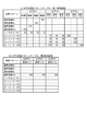
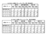
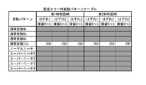
本実施形態の大当たり遊技における大入賞手段64の開放パターンとしては4R,6R,10Rの3種類設けられている(図34)。4R,6R,10Rの各開放パターンは、いわゆる出玉ありのラウンドを夫々4回,6回,10回行うように構成されている。ここで、出玉ありのラウンドは、大入賞手段64の開放後、その大入賞手段64への入賞個数が所定個数(例えば9個)に達するか、所定時間(例えば28秒)経過した時点で大入賞手段64を閉じるように設定されており、遊技者が右流下経路74b側の大入賞手段64を狙って右打ちをすれば最大個数の遊技球を容易に入賞させて大量の賞球を獲得できる。なお、出玉ありのラウンドに加えて、大入賞手段64が極短時間(例えば0.2秒)だけ開放する出玉なしのラウンドを有する開放パターンを設けてもよいし、出玉なしのラウンドのみの開放パターンを設けてもよい。
There are three types of opening patterns of the big winning means 64 in the big hit game of the present embodiment: 4R, 6R, and 10R (FIG. 34). Each of the 4R, 6R, and 10R open patterns is configured to perform so-called rounds with balls four, six, and ten times, respectively. Here, in the round with balls, after the large winning means 64 is opened, when the number of winnings to the large winning means 64 reaches a predetermined number (for example, 9) or a predetermined time (for example, 28 seconds) elapses. It is set to close the big prize means 64, and if the player hits right aiming at the big prize means 64 on the
また液晶表示手段66には、例えば第1,第2特別図柄表示手段53,54による第1,第2特別図柄の変動表示と並行して演出図柄80を変動表示可能である他、第1,第2特別保留個数を示す第1,第2保留画像X1〜X4,Y1〜Y4,変動中保留画像Z等の各種画像を表示可能となっている。
Further, on the liquid crystal display means 66, for example, the
ここで演出図柄80は、図3に示すように、例えば1〜8等の数字、その他で構成される図柄本体部80aと、この図柄本体部80aに付随するキャラクタその他の装飾部80bとの結合で構成され、例えば所定方向に複数列(ここでは左右方向に3列)で夫々変動可能であり、例えば第1,第2特別図柄の変動開始と略同時に所定の変動パターンに従って縦スクロール等による変動を開始すると共に、第1,第2特別図柄の変動停止と略同時に最終停止するようになっている。なお演出図柄80では、例えば全て同じ図柄で揃った場合が大当たり演出態様、それ以外が外れ演出態様となっており、第1,第2特別図柄が第1,第2大当たり態様(特定態様)となる場合には演出図柄80は大当たり演出態様(特定演出態様)となり、第1,第2特別図柄が第1,第2外れ態様(非特定態様)となる場合には演出図柄80は外れ演出態様(非特定演出態様)となる。
Here, as shown in FIG. 3, the
また第1,第2保留画像X1〜X4,Y1〜Y4,変動中保留画像Zに関しては、第1,第2特別図柄始動手段62,63が遊技球を検出することに基づいて第1,第2特別保留個数が増加した場合に、第1,第2保留画像X1〜,Y1〜を液晶表示手段66上に1個追加表示し、また第1,第2特別図柄表示手段53,54による第1,第2特別図柄の新たな変動が開始することに基づいて第1,第2特別保留個数が減少した場合に、例えば変動中保留画像Zを消去し、第1,第2保留画像X1〜,Y1〜を待ち行列の前側(例えば画面右側)に向けて1個分ずつシフトすると共に、押し出された先頭の第1,第2保留画像X1,Y1を例えば所定位置まで移動させて新たな変動中保留画像Zに変化させるようになっている。このように、液晶表示手段66が、保留記憶された第1,第2特別乱数情報の数に応じた保留表示を実行可能な保留表示手段の一例である。 Regarding the first and second reserved images X1 to X4, Y1 to Y4, and the changing pending image Z, the first and first first and second special symbol starting means 62 and 63 detect the game ball. 2 When the number of special reserved images increases, one additional first and second reserved images X1 to Y1 to be displayed on the liquid crystal display means 66, and the first and second special symbol display means 53 and 54 display the first and second images X1 to Y1 to the liquid crystal display means 66. When the number of first and second special reservations decreases based on the start of new fluctuations of the first and second special symbols, for example, the changing hold image Z is deleted and the first and second reserved images X1 to , Y1 to the front side of the queue (for example, the right side of the screen) by one, and the extruded first and second reserved images X1 and Y1 are moved to a predetermined position, for example, to make a new fluctuation. It is designed to be changed to the middle hold image Z. As described above, the liquid crystal display means 66 is an example of the hold display means capable of executing the hold display according to the number of the first and second special random number information stored in the hold.
また遊技盤16の裏側には、図5に示すように中央表示枠ユニット47等を後側から覆う裏カバー81が装着され、この裏カバー81の背面側に、主制御基板82aが格納された主基板ケース82、演出制御基板83a及び演出インターフェイス基板83bが格納された演出基板ケース83、液晶制御基板84aが格納された液晶基板ケース84等が着脱自在に装着されている。
Further, as shown in FIG. 5, a
また、前枠3の裏側には、遊技盤16の裏側を開閉自在に覆う開閉カバー85が着脱自在に装着されると共に、その上側に遊技球タンク86aとタンクレール86bとが、左右一側に払い出し手段28と払い出し通路87とが夫々装着されており、遊技球が大入賞手段64等の入賞口に入賞したとき、又は図外の自動球貸し機から球貸し指令があったときに、遊技球タンク86a内の遊技球をタンクレール86bを経て払い出し手段28により払い出し、その遊技球を払い出し通路87を経て上皿30に案内するようになっている。なお、開閉カバー85は、例えば主基板ケース82の上部側の一部分を後側から覆うように配置されている。
Further, on the back side of the
また、前枠3の裏側下部には、基板装着台88が着脱自在に装着されており、この基板装着台88の背面側に、電源基板89aが格納された電源基板ケース89、払出制御基板90aが格納された払出基板ケース90が夫々着脱自在に装着されている。
A
図6(a)は本パチンコ機の制御系の概略ブロック図である。図6(a)において、主制御基板82aは遊技制御動作を統括するもので、遊技盤16上の遊技情報表示手段50、普通図柄始動手段61、第1特別図柄始動手段62、第2特別図柄始動手段63、大入賞手段64、普通入賞手段65等が例えば図示しない中継基板等を経由して接続され、またその下位には、主制御基板82aからの制御コマンドに基づいて音声出力、電飾発光、可動体駆動等の演出制御を行う演出制御基板83a、この演出制御基板83aからの制御コマンドに基づいて液晶表示手段66を制御する液晶制御基板84a、主制御基板82aからの制御コマンドに基づいて払い出し手段28を制御する払出制御基板90a、この払出制御基板90aからの発射制御信号等に基づいて発射手段17を制御する発射制御基板91等のサブ制御手段が接続されている。
FIG. 6A is a schematic block diagram of the control system of this pachinko machine. In FIG. 6A, the
また主制御基板82aには、RAMクリアスイッチ92、設定変更操作手段93等の操作手段と、性能情報表示手段97等の表示手段とが接続されている。図5に示すように、RAMクリアスイッチ92と設定変更操作手段93とは何れも主基板ケース82の外側から操作可能な状態で、また性能情報表示手段97は主基板ケース82の外側から視認可能な状態で、夫々主制御基板82aに装着されている。なお本実施形態では、RAMクリアスイッチ92、設定変更操作手段93、性能情報表示手段97は、開閉カバー85で覆われない位置に配置している。
Further, the
RAMクリアスイッチ92は、電源投入時にRAMクリアを行う場合に操作するもので、主基板ケース82の外側から例えば押圧操作可能であり、非操作時にOFF、押圧操作時にONとなるように構成されている。また設定変更操作手段93は、設定変更を行う場合等に操作するもので、主基板ケース82の外側から例えば専用の設定キーを鍵穴部に差し込んで回転操作することによりON/OFFの切り替えが可能となっている。なお本実施形態では、この設定変更操作手段93等を操作することにより、大当たり確率、即ち第1,第2特別図柄が大当たり態様となる確率(乱数抽選で当選する確率)を複数段階(ここでは設定1〜6の6段階)に変更可能となっている。設定変更等の詳細については後述する。
The RAM
性能情報表示手段97は、設定表示手段94と性能表示手段95とを構成するもので、例えば4桁の7セグLED97a〜97dを備え、透明な主基板ケース82を通して視認可能となるように例えば主基板ケース82内で主制御基板82aに装着されており、第1期間中は設定表示手段94として機能し、第1期間とは異なる第2期間中は性能表示手段95として機能するようになっている。
The performance information display means 97 constitutes the setting display means 94 and the performance display means 95, and includes, for example, 4-digit 7-
設定表示手段94は、設定1〜6の何れが選択されているかを示す設定情報を表示するもので、例えば設定1〜6に対応して「1」〜「6」、「1.」〜「6.」の何れかを性能情報表示手段97の少なくとも一部(ここでは7セグLED97a)に表示可能であり、例えば設定変更期間中は確定前の設定情報をドット付きの「1.」〜「6.」で、設定確認期間中は確定された設定情報をドットなしの「1」〜「6」で夫々表示可能となっている。
The setting display means 94 displays setting information indicating which of
性能表示手段95は、いわゆるベース値を7セグLED97a〜97dに表示するものである。ベース値は、遊技実績に基づいて得られる性能情報の一例であり、例えば「(低確率状態での払い出し個数÷低確率状態でのアウト個数)×100」で算出される。なお本実施形態の性能表示手段95は、第1ベース値,第2ベース値の2種類のベース値を切り替え表示可能となっている。第1ベース値は、所定時点からアウト個数が所定個数(例えば60000個)に達するまでを単位期間としてその単位期間中におけるリアルタイムでのベース値であり、第2ベース値は前回の単位期間における累計のベース値である。もちろん、例えば前々回の単位時間における累計のベース値を第3ベース値として表示する等、3種類以上のベース値を切り替え可能としてもよい。
The performance display means 95 displays a so-called base value on the 7-
以上のように、RAMクリアスイッチ92、設定変更操作手段93、性能情報表示手段97(設定表示手段94及び性能表示手段95)は、何れも遊技機本体1の後側に配置されており、それらにアクセスするためには解錠して前枠3を開放する必要があるため、ホール関係者等以外はRAMクリアスイッチ92、設定変更操作手段93を操作することができず、また性能情報表示手段97(設定表示手段94、性能表示手段95)の表示内容を見ることもできない。
As described above, the RAM
また本実施形態では、遊技情報表示手段50と性能情報表示手段97とについてダイナミック点灯方式により駆動制御を行うようになっている。図7に示すように、主制御基板82aのLEDコモンポートからは1バイトのダイナミック点灯コモンC0〜C7の走査信号を出力可能であり、それらのうち、ダイナミック点灯コモンC0〜C3のラインが遊技情報表示手段50のLEDグループ50a〜50dに、ダイナミック点灯コモンC4〜C7のラインが性能情報表示手段97の7セグ表示部97a〜97dに夫々接続されている。
Further, in the present embodiment, the game information display means 50 and the performance information display means 97 are driven and controlled by a dynamic lighting method. As shown in FIG. 7, 1-byte dynamic lighting commons C0 to C7 can be output from the LED common port of the
また、主制御基板82aのLEDデータポート1,2からは夫々1バイトのダイナミック点灯データD10〜D17,D20〜D27を出力可能であり、LEDデータポート1のダイナミック点灯データD10〜D17のラインが遊技情報表示手段50のLEDグループ50a〜50dに、LEDデータポート2のダイナミック点灯データD20〜D27のラインが性能情報表示手段97の7セグ表示部97a〜97dに夫々接続されている。
Further, 1-byte dynamic lighting data D10 to D17 and D20 to D27 can be output from the
演出制御基板83a及び液晶制御基板84aは、図6(a)に示すように主制御基板82aに接続された演出インターフェイス基板83bに接続されており、主制御基板82aから演出制御基板83aへの制御コマンド、演出制御基板83aから液晶制御基板84aへの制御コマンドは共に演出インターフェイス基板83bを経由して送信されるようになっている。
The
また、演出制御基板83aの制御対象である各種演出手段、例えばスピーカ18,25、電飾手段96、可動演出手段67等の他、遊技者が操作可能な演出ボタン34、十字操作手段35等は例えば演出インターフェイス基板83bを介して演出制御基板83aに接続されている。なお、電飾手段96は、上下の装飾カバー27,33内や遊技盤16等に配置された多数のLED(図示省略)により構成されている。
Further, various effect means to be controlled by the
続いて、電源投入時に主制御基板82aにおいて実行される電源投入処理(図8)について説明する。この電源投入処理(図8)では、まずタイマ割込み等の割込み処理が実行されないように割込み禁止とし(S1)、スタックポインタを設定する(S2)と共に、第1電源異常チェック処理でのスタック使用に備えて、RAMのプロテクト及び禁止領域を無効とする(S3)。そして、後述する設定変更処理中に電源のOFF/ONが行われた可能性を考慮して、外部出力端子から出力するセキュリティ信号をOFFにすると共に、設定表示手段94への設定情報の表示に関する設定表示用データをクリアし、また不用意な発射許可信号の出力を防止すべく発射許可信号もOFFにする(S4)。
Subsequently, the power-on process (FIG. 8) executed on the
続いて、第1電源異常チェック処理(S5)を実行する。この第1電源異常チェック処理では、図11に示すように、WDTクリア処理(S51a)を実行した後、電源異常信号がONであるか否かを判定し(S51)、電源異常信号がONであれば(S51:Yes)、電源投入処理の冒頭(図8のS1)に移行するようになっている。 Subsequently, the first power supply abnormality check process (S5) is executed. In this first power supply abnormality check process, as shown in FIG. 11, after executing the WDT clear process (S51a), it is determined whether or not the power supply abnormality signal is ON (S51), and the power supply abnormality signal is ON. If there is (S51: Yes), the process proceeds to the beginning of the power-on process (S1 in FIG. 8).
第1電源異常チェック処理(S5)で電源異常信号がONでないと判定された場合には(図11のS51:No)、そのまま第1電源異常チェック処理を終了し、次のS6(図8)に移行する。このS6では、CPU内のレジスタ値等に関する各種初期設定を行うと共に、割込みモード、割込み優先順位、内部ハード乱数等の設定を行う。そして、サブ基板起動待ち時間をセットし(S7)、サブ基板起動待ち時間が0になるまで(S11)、サブ基板起動待ち時間の減算処理(S8)、WDTクリア処理(S9)、S5と同様の第1電源異常チェック処理(S10,図11)を繰り返し実行する。 If it is determined in the first power supply abnormality check process (S5) that the power supply abnormality signal is not ON (S51: No in FIG. 11), the first power supply abnormality check process is terminated as it is, and the next S6 (FIG. 8). Move to. In this S6, various initial settings related to register values in the CPU and the like are performed, and interrupt modes, interrupt priority, internal hard random numbers, and the like are set. Then, the sub-board start-up waiting time is set (S7), until the sub-board start-up waiting time becomes 0 (S11), the sub-board start-up waiting time subtraction process (S8), the WDT clear process (S9), and the same as in S5. The first power supply abnormality check process (S10, FIG. 11) is repeatedly executed.
サブ基板起動待ち時間が0になると(S11:Yes)、演出制御基板83aに対して待機画面表示コマンド(BA01H)を送信する(S12)。演出制御基板83aが待機画面表示コマンド(BA01H)を受信すると、例えば液晶表示手段66には「Please Wait」等の表示が行われる(図44)。
When the sub-board start-up waiting time becomes 0 (S11: Yes), a standby screen display command (BA01H) is transmitted to the
そして、払出制御基板90aの電源投入信号がONであると判定されるまで(S14:Yes)、第1電源異常チェック処理(S13,図11)を繰り返し実行することにより、払出制御基板90aの起動確認を行う。
Then, the
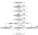
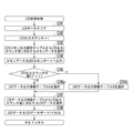
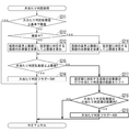
続いて図9に示すS15〜S24の処理に移行する。このS15〜S24の処理は、設定変更処理(S17)及びRAMクリア処理(S18)を実行する「設定変更」、設定変更処理(S17)を実行することなくRAMクリア処理(S18)を実行する「RAMクリア」、設定確認処理(S23)及びバックアップ復帰処理(S24)を実行する「設定確認」、設定確認処理(S23)を実行することなくバックアップ復帰処理(S24)を実行する「バックアップ復帰」、電源再投入待ち処理(S20)を実行する「RAM異常」の5種類の処理態様の何れかで行われる。 Subsequently, the process proceeds to the processes S15 to S24 shown in FIG. The processes of S15 to S24 include "setting change" for executing the setting change process (S17) and RAM clear process (S18), and executing the RAM clear process (S18) without executing the setting change process (S17). "RAM clear", "setting confirmation" to execute setting confirmation processing (S23) and backup restoration processing (S24), "backup restoration" to execute backup restoration processing (S24) without executing setting confirmation processing (S23), It is performed in any of five types of processing modes of "RAM error" that executes the power re-on wait process (S20).
また、これら5種類の処理態様のうち、「RAM異常」を除く4種類については、設定変更操作手段93のON/OFF状態、扉(前枠3)の開放/閉鎖状態、RAMクリアスイッチ92のON/OFF状態の組み合わせに応じて選択される。
Further, among these five types of processing modes, for four types excluding "RAM abnormality", the setting change operation means 93 is in the ON / OFF state, the door (front frame 3) is in the open / closed state, and the RAM
本実施形態では、図14に示すように、設定変更操作手段93とRAMクリアスイッチ92とが共にONの場合には原則として「設定変更」が選択され、設定変更操作手段93がOFF、RAMクリアスイッチ92がONの場合には「RAMクリア」が選択されるが、設定変更操作手段93とRAMクリアスイッチ92とが共にONであっても、扉開放の場合には「設定変更」ではなく「RAMクリア」が選択されるようになっている。また同様に、設定変更操作手段93がON、RAMクリアスイッチ92がOFFの場合には原則として「設定確認」が選択され、設定変更操作手段93とRAMクリアスイッチ92とが共にOFFの場合には「バックアップ復帰」が選択されるが、設定変更操作手段93がON、RAMクリアスイッチ92がOFFであっても、扉開放の場合には「設定確認」ではなく「バックアップ復帰」が選択されるようになっている。
In the present embodiment, as shown in FIG. 14, when both the setting change operation means 93 and the RAM
このように本実施形態では、扉(前枠3)が開放していないにも拘わらず設定変更操作手段93やRAMクリアスイッチ92がONであるという状況は不正行為が疑われることから、設定変更機能に関する「設定変更」及び「設定確認」については扉開放を条件とし、扉閉鎖の場合には、設定変更処理(S17)を実行しない「RAMクリア」、設定確認処理(S23)を実行しない「バックアップ復帰」を選択するようになっている。なお、設定変更機能に関係しない「RAMクリア」、「バックアップ復帰」については、設定変更操作手段93及びRAMクリアスイッチ92のON/OFF状態のみを条件とし、扉の開放/閉鎖状態は条件としていない。
As described above, in the present embodiment, the setting change operation means 93 and the RAM
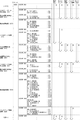
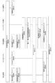
以下、S15〜S24の処理について、図9のフローチャートを参照しつつ、図12に示すソースプログラムに従って詳細に説明する。なお図12には、S15〜S24のソースプログラムが、メモリ上の記憶順序に沿って記載されている。また、そのソースプログラムの右側には、上述した「設定変更」、「RAMクリア」、「設定確認」、「バックアップ復帰」、「RAM異常」の5種類の処理態様毎に、実行する処理とそれらの実行順序とを、矢印とその右上の数字とで示している。 Hereinafter, the processes of S15 to S24 will be described in detail according to the source program shown in FIG. 12 with reference to the flowchart of FIG. Note that FIG. 12 shows the source programs S15 to S24 in the storage order in the memory. In addition, on the right side of the source program, the processes to be executed and those are executed for each of the above-mentioned five types of processing modes of "setting change", "RAM clear", "setting confirmation", "backup recovery", and "RAM error". The execution order of is indicated by an arrow and the number on the upper right.
入力ポートデータ取得処理(S15)では、図12に示すように、まず入力ポート1(P_INPT1)のデータをWレジスタに入力する(Sa1)。本実施形態では、入力ポート1(P_INPT1)の第0〜7ビットに対応する入力信号は図13に示すようになっており、設定変更操作手段93のON/OFF信号は第0ビットに、扉開放スイッチ44のON/OFF信号(扉開放信号)は第5ビットに、RAMクリアスイッチ92のON/OFF信号は第6ビットに、夫々入力される。Sa1では、その入力ポート1(P_INPT1)の第0〜7ビットのデータがWレジスタの第0〜7ビットに夫々入力される。
In the input port data acquisition process (S15), as shown in FIG. 12, first, the data of the input port 1 (P_INPT1) is input to the W register (Sa1). In the present embodiment, the input signal corresponding to the 0th to 7th bits of the input port 1 (P_INPT1) is as shown in FIG. 13, and the ON / OFF signal of the setting change operation means 93 is set to the 0th bit and the door. The ON / OFF signal (door opening signal) of the
次に、Wレジスタの値とマスクデータ“01100001B”との論理積(AND)を求めることにより、設定変更操作手段93のON/OFF信号に対応する第0ビット、扉開放スイッチ44のON/OFF信号(扉開放信号)に対応する第5ビット、RAMクリアスイッチ92のON/OFF信号に対応する第6ビット以外のビットをマスクし、Wレジスタをそのマスク後のデータに更新する(Sa2)。
Next, by obtaining the logical product (AND) of the value of the W register and the mask data "01100001B", the 0th bit corresponding to the ON / OFF signal of the setting change operation means 93, the ON / OFF of the
図14に示すように、Wレジスタの第0ビットは、設定変更操作手段93がONの場合に1、OFFの場合に0となり、同じく第5ビットは、扉(前枠3)が開放している場合に1、閉鎖している場合に0となり、同じく第6ビットは、RAMクリアスイッチ92がONの場合に1、OFFの場合に0となる。なお、Wレジスタの第0,5,6ビットの値の組み合わせは図14に示す8種類存在する。以下の説明では、Wレジスタの第0,5,6ビットの値w0,w5,w6の組み合わせを、必要に応じてW(w0,w5,w6)で表現する。
As shown in FIG. 14, the 0th bit of the W register becomes 1 when the setting change operation means 93 is ON and 0 when the setting change operation means 93 is OFF, and the door (front frame 3) of the 5th bit is also opened. When it is, it becomes 1, when it is closed, it becomes 0, and similarly, the sixth bit becomes 1 when the RAM
以上の入力ポートデータ取得処理(S15)に続いては、設定変更分岐判定処理(S16)を実行する。この設定変更分岐判定処理(設定変更判定処理)(S16)は、処理態様として「設定変更」を選択するか否かを判定するもので、図12に示すように、まずWレジスタの値と“01100001B”とを比較してそれらの差を求める(Sb1)。これにより得られる値は、Wレジスタの第0,5,6ビットが全て1の場合(W(1,1,1))、即ち扉(前枠3)が開放し、設定変更操作手段93とRAMクリアスイッチ92とが共にONの場合に0となる。なお、得られた値(差)が0であれば例えばゼロフラグに1がセットされる。そして、Sb1で得られた値が0であれば(ゼロフラグ=1)、即ちW(1,1,1)であれば、処理態様として「設定変更」が選択され、次の設定変更処理(S17)へと移行する。
Following the above input port data acquisition process (S15), the setting change branch determination process (S16) is executed. This setting change branch determination process (setting change determination process) (S16) determines whether or not to select "setting change" as the processing mode. As shown in FIG. 12, first, the value of the W register and " 01100001B "is compared with the difference between them (Sb1). The value obtained by this is when the 0th, 5th, and 6th bits of the W register are all 1 (W (1,1,1)), that is, the door (front frame 3) is opened, and the setting changing operation means 93 is used. It becomes 0 when both the RAM
設定変更処理(S17)では、まず設定変更期間が開始したことを示すBA5AH(設定変更中コマンドデータ)をDEレジスタに格納し(Sc1)、コマンド送信処理(Sc2)によってそのコマンドデータを送信する。なお、演出制御基板83aが設定変更中コマンド(BA5AH)を受信すると、例えば液晶表示手段66には「設定変更中です」等の表示が行われる(図44)。
In the setting change process (S17), first, BA5AH (command data during setting change) indicating that the setting change period has started is stored in the DE register (Sc1), and the command data is transmitted by the command transmission process (Sc2). When the
次に、設定処理のサブルーチン(M_SETTEI)を実行する(Sc3)。この設定処理(Sc3)では、図15(a)に示すように、まずバックアップフラグをクリアする(S60)と共に入力データ作成処理(S61)を実行する。この入力データ作成処理(S61)は、RAMクリアスイッチ92、設定変更操作手段93等の入力情報を取得するもので、例えばタイマ割込み処理における入力管理処理(図24のS133)から呼び出されるようになっている。
Next, the setting processing subroutine (M_SETTEI) is executed (Sc3). In this setting process (Sc3), as shown in FIG. 15A, first, the backup flag is cleared (S60) and the input data creation process (S61) is executed. This input data creation process (S61) acquires input information of the RAM
次に、RAMの設定値ワーク領域から設定値データを読み出して設定作業値として例えばCレジスタにセットする(S62)。本実施形態では、設定1〜6の何れかを選択可能であり、RAM上の設定値ワーク領域には、それら設定1〜6の何れが選択されているかに応じて例えば0〜5の何れかの設定値データが格納されている。そして、Cレジスタの設定作業値が0〜5の範囲内にない場合には(S63:No)、Cレジスタ(設定作業値)に例えば0を格納する(S64)。即ち、設定値データが正常範囲内になければ、Cレジスタ(設定作業値)に設定1に対応する0を強制的にセットする。もちろん、Cレジスタ(設定作業値)にセットする値は0に限られるものではなく、正常範囲内(0〜5)の何れかであればよい。
Next, the set value data is read from the set value work area of the RAM and set as the set work value in, for example, the C register (S62). In the present embodiment, any of the
本実施形態の場合、設定変更処理(S17)の前には後述するRAM異常判定処理(S19)が実行されないため、設定変更処理(S17)の開始時点でRAM異常により設定値ワーク領域の値が正常範囲内にない可能性がある。そこでそのような場合には、S64で設定作業値に正常値(ここでは0)を強制的にセットすることにより、RAM異常の場合でも設定変更処理を進めることができるようにしている。 In the case of the present embodiment, since the RAM abnormality determination process (S19) described later is not executed before the setting change process (S17), the value of the set value work area is changed due to the RAM abnormality at the start of the setting change process (S17). It may not be within the normal range. Therefore, in such a case, the normal value (here, 0) is forcibly set in the setting work value in S64 so that the setting change process can proceed even in the case of a RAM abnormality.
続いて、第1電源異常チェック処理(S65,図11)を実行し、セキュリティ信号を外部出力端子から出力する(S66)。そして、チャタリング防止待ち時間をセットし(S67)、そのチャタリング防止待ち時間が0になるまで(S69:Yes)、チャタリング防止待ち時間の減算処理(S68)を繰り返し実行する。本実施形態では、設定変更操作手段93がOFFになるまで(S76:Yes)、S65〜S75の処理が高速で繰り返され、その度に設定変更操作がなされたか否か、即ちRAMクリアスイッチ92がOFF→ONに変化したか否かが判定されるが(後述するS71)、S67〜S69によりチャタリング防止待ち時間を設けることにより、RAMクリアスイッチ92のチャタリングによる誤検出を防止できる。
Subsequently, the first power supply abnormality check process (S65, FIG. 11) is executed, and the security signal is output from the external output terminal (S66). Then, the chattering prevention waiting time is set (S67), and the chattering prevention waiting time subtraction process (S68) is repeatedly executed until the chattering prevention waiting time becomes 0 (S69: Yes). In the present embodiment, the processes of S65 to S75 are repeated at high speed until the setting change operation means 93 is turned off (S76: Yes), and whether or not the setting change operation is performed each time, that is, the RAM
チャタリング防止待ち時間が0になると(S69:Yes)、入力データ作成処理(S70)を実行し、所定の設定変更操作が行われたか否かを判定する(S71)。本実施形態では、RAMクリアスイッチ92を設定変更操作用にも利用しており、S71ではRAMクリアスイッチ92のONエッジを検出した場合に設定変更操作が行われたものと判定するようになっている。なお本実施形態では、RAMクリアスイッチ92の入力情報を取得する入力データ作成処理を、S71の直前のS70だけでなく、設定処理の開始直後のS61でも実行するようになっている。これは、RAMクリアスイッチ92が押下されたままの状態で設定処理(図15(a))が開始された場合に、いきなりRAMクリアスイッチ92のONエッジが立ってしまったとしても、それをS61で空検出することにより、S71での判断に影響を与えないようにするためである。
When the chattering prevention waiting time becomes 0 (S69: Yes), the input data creation process (S70) is executed, and it is determined whether or not a predetermined setting change operation has been performed (S71). In the present embodiment, the RAM
そして、S71で設定変更操作が行われたと判定されることを条件に(S71:Yes)、設定作業値の更新処理(S72〜S74)を実行する。即ち、設定作業値をインクリメントし(S72)、インクリメント後の設定作業値が0〜5の範囲内にない場合(S73:No)には設定作業値に0をセットする(S74)。 Then, on condition that it is determined that the setting change operation has been performed in S71 (S71: Yes), the setting work value update processing (S72 to S74) is executed. That is, the set work value is incremented (S72), and when the set work value after the increment is not within the range of 0 to 5 (S73: No), 0 is set to the set work value (S74).
次に、設定作業値に基づいて、設定表示手段94に表示する設定情報を指定するための設定表示用データを作成し、出力する(S75)。このS75の処理を、図15(b)に示すソースプログラムに従って具体的に説明すると、まず設定表示データテーブルの先頭アドレスをHLレジスタにセットする(S75a)。設定表示データテーブルは、図15(c)に示すように、設定1〜6の6種類の設定情報に対応する各1バイトの表示パターンデータで構成されている。
Next, based on the setting work value, setting display data for designating the setting information to be displayed on the setting display means 94 is created and output (S75). The process of S75 will be specifically described according to the source program shown in FIG. 15 (b). First, the start address of the setting display data table is set in the HL register (S75a). As shown in FIG. 15C, the setting display data table is composed of 1-byte display pattern data corresponding to the 6 types of setting information of
次に、Cレジスタに格納されている設定作業値(S62〜S64参照)をAレジスタに転送し(S75b)、HLレジスタの値(設定表示データテーブルの先頭アドレス)にAレジスタの値(設定作業値)を加算して得られたアドレス(設定表示データテーブルにおける設定作業値0〜5の何れかに対応するアドレス)から表示パターンデータを読み出してWレジスタにセットする(S75c)。これにより、Wレジスタには、例えば設定作業値が0であれば「1」を表示するための“00000110B”が、設定作業値が5であれば「6」を表示するための“01111101B”がセットされる。
Next, the setting work value (see S62 to S64) stored in the C register is transferred to the A register (S75b), and the value of the A register (setting work) is set to the value of the HL register (start address of the setting display data table). The display pattern data is read from the address obtained by adding the value) (the address corresponding to any of the setting
そして、そのWレジスタの値と、「.(ドット)」に対応する表示パターンデータである“10000000B”との論理和(OR)を求めてWレジスタの値を更新する(S75d)。これにより、Wレジスタにセットされている表示パターンデータは、「1」〜「6」に「.(ドット)」を付加した「1.」〜「6.」の何れかとなる。 Then, the value of the W register is updated by obtaining the logical sum (OR) of the value of the W register and the display pattern data "10000000B" corresponding to ". (Dot)" (S75d). As a result, the display pattern data set in the W register becomes any of "1." to "6." in which ". (Dot)" is added to "1" to "6".
次に、7セグ表示部97aに対応するコモンC4(図7)をONにするコモンデータ“00010000B”をAレジスタにセットし(S75e)、Aレジスタの値をLEDコモンポート(図7)に、Wレジスタの値をLEDデータポート2(図7)に夫々出力する(S75f)。これにより、設定作業値(0〜5の何れか)に対応して「1.」〜「6.」の何れかが設定表示手段94、即ち性能情報表示手段97の7セグ表示部97aに表示される。
Next, the common data "00010000B" for turning on the common C4 (FIG. 7) corresponding to the 7-
このように、S75では設定作業値に基づいて設定表示用データを作成するため、設定変更期間中に設定表示手段94に表示される値(例えば1〜6の何れか)はその時点の設定情報(設定値ワーク領域の値)ではなく、確定前の暫定的な設定情報を示している。また、そのことを明示すべく、設定表示手段94には「1」〜「6」に「.(ドット)」を付加して表示するようになっている。もちろん、例えば「1」〜「6」を点滅表示する等、「.(ドット)」の付加以外の方法で確定前の設定情報である旨を明示してもよい。 In this way, in S75, since the setting display data is created based on the setting work value, the value displayed on the setting display means 94 during the setting change period (for example, any of 1 to 6) is the setting information at that time. It shows the provisional setting information before confirmation, not (setting value work area value). Further, in order to clarify this, the setting display means 94 is displayed by adding ". (Dot)" to "1" to "6". Of course, for example, "1" to "6" may be blinked and displayed, and it may be clearly indicated that the setting information is before confirmation by a method other than the addition of ". (Dot)".
以上のS65〜S75の処理を、設定変更終了条件が満たされるまで(S76:Yes)繰り返し実行する。本実施形態では、設定変更操作手段93のOFFエッジを検出した場合に設定変更終了条件が満たされたと判定する。以上の処理により、設定変更期間中は、RAMクリアスイッチ92の押下回数に応じて設定作業値が0〜5の範囲で循環的に変更される。
The above processes S65 to S75 are repeatedly executed until the setting change end condition is satisfied (S76: Yes). In the present embodiment, when the OFF edge of the setting change operation means 93 is detected, it is determined that the setting change end condition is satisfied. By the above processing, during the setting change period, the set work value is cyclically changed in the range of 0 to 5 according to the number of times the RAM
設定変更期間中に設定変更終了条件が満たされると(S76:Yes)、設定変更期間を終了し、Cレジスタの設定作業値を、設定値ワーク領域に格納する(S77)。これにより、設定変更期間中にRAMクリアスイッチ92の操作により変更された暫定的な設定作業値が設定値データとして確定する。そして、設定表示用データをクリアして設定表示手段94による設定情報の表示を終了する(S78)と共に、セキュリティ信号をOFFにし(S79)、演出制御基板83aに対して設定変更完了コマンド(BA09H)を送信し(S80)、設定処理を終了する。なお、演出制御基板83aが設定変更完了コマンド(BA09H)を受信すると、例えば液晶表示手段66には「設定が変更されました」等の表示が行われる(図44)。
When the setting change end condition is satisfied during the setting change period (S76: Yes), the setting change period ends and the setting work value of the C register is stored in the set value work area (S77). As a result, the provisional set work value changed by the operation of the RAM
このように本実施形態では、電源投入時に設定変更操作手段93とRAMクリアスイッチ92とが共にONで且つ扉開放中である場合(Wレジスタの第0,5,6ビットが全て1の場合)には、設定変更操作手段93がOFFに切り替えられるまでの設定変更期間中、設定表示手段94に表示される設定情報(例えば「1.」〜「6.」の何れか)を参照しつつ、RAMクリアスイッチ92を押下することによって設定作業値を設定1〜6の範囲で変更することができ、その後に設定変更操作手段93をOFFに切り替えることによってその暫定の設定作業値を設定値データとして確定させることができる。
As described above, in the present embodiment, when the setting change operation means 93 and the RAM
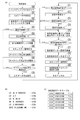
図12に戻って説明を続ける。以上の設定処理(Sc3)が終了すると、設定変更時コマンド送信アドレステーブルのアドレス(D_MKCADR2A)をHLレジスタにセットする(Sc4)。ここで、設定変更時コマンド送信アドレステーブルは、この設定変更時に送信するコマンドを作成するためのコマンド作成テーブルを指定するもので、ループ数と、そのループ数分のコマンド作成テーブルのアドレスとで構成されている。図16(a1)に示す設定変更時コマンド送信アドレステーブルでは、ループ数が2に設定されると共に、スペックコマンド作成テーブル、客待ち中コマンド作成テーブルの2種類のコマンド作成テーブルのアドレスが設定されている。 The explanation will be continued by returning to FIG. When the above setting process (Sc3) is completed, the address (D_MKCADR2A) of the command transmission address table at the time of setting change is set in the HL register (Sc4). Here, the command transmission address table at the time of setting change specifies the command creation table for creating the command to be transmitted at the time of this setting change, and is composed of the number of loops and the address of the command creation table for the number of loops. Has been done. In the command transmission address table at the time of setting change shown in FIG. 16 (a1), the number of loops is set to 2, and the addresses of two types of command creation tables, the spec command creation table and the waiting command creation table, are set. There is.
そして、SYSTEM_550、即ちRAMクリア処理(S18)のSd2へとジャンプする(Sc5)。このように本実施形態では、設定変更処理(S17)に続くRAMクリア処理(S18)は、Sd1をスキップしてSd2から実行される。 Then, it jumps to SYSTEM_550, that is, Sd2 of the RAM clear process (S18) (Sc5). As described above, in the present embodiment, the RAM clear process (S18) following the setting change process (S17) is executed from Sd2, skipping Sd1.
なお、このSc5のジャンプ処理では、絶対アドレスジャンプの「JP」命令ではなく、相対アドレスジャンプの「JR」命令を用いている。絶対アドレスジャンプの「JP」命令では、ジャンプ先アドレスを絶対アドレス(2バイト)で指定するのに対し、相対アドレスジャンプの「JR」命令では、ジャンプ先のアドレスを相対アドレス(1バイト)で指定するため、「JR」命令の方が1バイト分プログラム容量を削減できるという利点がある。但し、「JR」命令の場合には、ジャンプ先に指定可能な範囲が「JP」命令に比べて制限され、PCレジスタの場所から−128〜+127バイトの範囲となるため、その範囲を超えてジャンプする場合には使用できない。本実施形態では、図12に示すソースプログラムで使用しているジャンプ命令は全て「JR」命令となっている。 In this Sc5 jump process, the relative address jump "JR" instruction is used instead of the absolute address jump "JP" instruction. In the absolute address jump "JP" instruction, the jump destination address is specified by the absolute address (2 bytes), whereas in the relative address jump "JR" instruction, the jump destination address is specified by the relative address (1 byte). Therefore, the "JR" instruction has an advantage that the program capacity can be reduced by one byte. However, in the case of the "JR" instruction, the range that can be specified as the jump destination is limited compared to the "JP" instruction, and it is in the range of -128 to +127 bytes from the location of the PC register, so it exceeds that range. Cannot be used when jumping. In this embodiment, all the jump instructions used in the source program shown in FIG. 12 are "JR" instructions.
RAMクリア処理(S18)のSd2では、HLレジスタに指定されているコマンド送信アドレステーブルに基づいて送信コマンドテーブル選択処理を実行する。なお、設定変更処理(S17)からSd2にジャンプしてきた場合、HLレジスタには設定変更時コマンド送信アドレステーブル(図16(a1))のアドレスがセットされている。 In Sd2 of the RAM clear process (S18), the transmission command table selection process is executed based on the command transmission address table specified in the HL register. When jumping from the setting change process (S17) to Sd2, the address of the command transmission address table (FIG. 16 (a1)) at the time of setting change is set in the HL register.
送信コマンドテーブル選択処理(Sd2)では、例えば図17に示すように、まず指定されたコマンド送信アドレステーブルからループ数を取得し(S81)、以下のS82,S83をそのループ数だけ繰り返し実行する(S84)。S82では、指定されたコマンド送信アドレステーブルからコマンド作成テーブルのアドレスを指定し、S83ではその指定されたコマンド作成テーブルに基づいてコマンドデータ作成処理を実行する。図16(a1)に示す設定変更時コマンド送信アドレステーブルの場合、2回のループでスペックコマンド作成テーブル(図16(c))、客待ち中コマンド作成テーブル(図16(d))のアドレスが順次指定され、夫々コマンドデータ作成処理が実行される。 In the transmission command table selection process (Sd2), for example, as shown in FIG. 17, the number of loops is first acquired from the specified command transmission address table (S81), and the following S82 and S83 are repeatedly executed by the number of loops (Sd2). S84). In S82, the address of the command creation table is specified from the designated command transmission address table, and in S83, the command data creation process is executed based on the designated command creation table. In the case of the command transmission address table at the time of setting change shown in FIG. 16 (a1), the addresses of the spec command creation table (FIG. 16 (c)) and the customer waiting command creation table (FIG. 16 (d)) are obtained in two loops. It is specified sequentially and the command data creation process is executed respectively.
コマンドデータ作成処理(S83)では、例えば図18に示すように、指定されたコマンド作成テーブルからコマンドデータを作成し(S91)、そのコマンドデータを送信するためのコマンド送信処理(S92)を実行する。コマンド作成テーブルには、図16(c),(d)等に示すように、コマンドデータの他にそのコマンドデータに対する加算値が設定されており、S91では、コマンド作成テーブルから取得したコマンドデータに加算値を加算して、実際に送信するコマンドデータを作成する。設定変更時コマンド送信アドレステーブルで指定された図16(c),(d)に示すコマンド作成テーブルの場合、加算値は何れも0に設定されているため、各コマンド作成テーブルからF611H(スペックコマンドデータ)、BA04H(客待ち中コマンドデータ)が順次取得され、そのまま送信される。 In the command data creation process (S83), for example, as shown in FIG. 18, command data is created from the designated command creation table (S91), and the command transmission process (S92) for transmitting the command data is executed. .. In the command creation table, as shown in FIGS. 16C and 16D, an additional value for the command data is set in addition to the command data. In S91, the command data acquired from the command creation table is set. Add the added values to create the command data to be actually sent. In the case of the command creation table shown in FIGS. 16 (c) and 16 (d) specified in the command transmission address table at the time of setting change, since the added value is set to 0, F611H (spec command) is displayed from each command creation table. Data) and BA04H (command data waiting for customers) are sequentially acquired and transmitted as they are.
以上の送信コマンドテーブル選択処理(図12のSd2)に続いては、設定値ワークの次のアドレスをHLレジスタにセットし(Sd3)、0クリア処理の回数(ここでは256−3)をBレジスタにセットする(Sd4)と共に、0クリア処理をコールする(Sd5)。本実施形態では、RAM上の0〜255バイトの範囲が領域内のワークエリア(領域内RAM)として、また256〜511バイトの範囲が領域外のワークエリア(領域外RAM)として夫々割り当てられており、領域内RAMの先頭が設定値ワーク領域となっている。また、領域内RAMの末尾から所定バイト分はスタック領域として使用され、例えばSd5においてはサブルーチンコール後の復帰アドレスが一時的に格納されるようになっている。従って、上記Sd3〜Sd5により、設定値ワーク領域と、サブルーチンコール後の復帰アドレスが格納されたスタック領域とを除く領域内RAMの253バイト分の領域が0クリアされる。 Following the above transmission command table selection process (Sd2 in FIG. 12), the next address of the set value work is set in the HL register (Sd3), and the number of 0 clear processes (256-3 in this case) is set in the B register. At the same time as setting to (Sd4), 0 clear processing is called (Sd5). In the present embodiment, the range of 0 to 255 bytes on the RAM is allocated as the work area within the area (RAM within the area), and the range of 256 to 511 bytes is allocated as the work area outside the area (RAM outside the area). The head of the RAM in the area is the set value work area. Further, a predetermined byte from the end of the RAM in the area is used as a stack area. For example, in Sd5, the return address after the subroutine call is temporarily stored. Therefore, the Sd3 to Sd5 clear the area of 253 bytes of the RAM in the area excluding the set value work area and the stack area in which the return address after the subroutine call is stored.
続いて、初期値設定データテーブルの先頭アドレスをHLレジスタにロードし(Sd6)、データセット処理をコールすることにより(Sd7)、一部のデータに初期値を設定した後、SYSTEM_1200、即ち図10に示すS25へとジャンプする(Sd8)。 Subsequently, the start address of the initial value setting data table is loaded into the HL register (Sd6), and the data set processing is called (Sd7) to set the initial value for some data, and then SYSTEM_1200, that is, FIG. Jump to S25 shown in (Sd8).
このように、電源投入時のRAMクリア処理(S18)では、領域内RAMと領域外RAMとのうち、領域内RAMのみが初期化され、領域外RAMは初期化されない。なお、領域外RAMは、主に性能表示手段95の表示に関するデータを記憶する領域であり、カウント値、計数値、表示値などのデータが記憶される。領域内RAMは、領域外RAMに記憶された性能表示手段95以外の遊技に関するデータが記憶される。このように、RAM領域を区分し、電源投入時のRAMクリア処理では領域外RAMを初期化しないようにすることで、RAMクリア処理が行われた場合であっても性能表示手段95に関するカウント値、計数値、表示値などのデータを電断を跨いで引き継ぐことが可能である。 As described above, in the RAM clearing process (S18) at the time of turning on the power, only the intra-region RAM is initialized out of the in-region RAM and the out-of-region RAM, and the out-of-region RAM is not initialized. The out-of-area RAM is an area that mainly stores data related to the display of the performance display means 95, and stores data such as a count value, a count value, and a display value. The intra-region RAM stores data related to games other than the performance display means 95 stored in the out-of-region RAM. In this way, by dividing the RAM area and preventing the out-of-area RAM from being initialized in the RAM clear process when the power is turned on, the count value related to the performance display means 95 even when the RAM clear process is performed. , Counted values, displayed values, etc. can be inherited across power interruptions.
S16の設定変更分岐判定処理に戻って説明を続ける。このS16でWレジスタの第0,5,6ビットの少なくとも1つが1でない(≠W(1,1,1))と判定した場合、即ち「設定変更」の処理態様が選択されなかった場合には、図12のSYSTEM_600、即ちRAM異常判定処理(S19)へとジャンプする(Sb2)。 The description will be continued by returning to the setting change branch determination process in S16. When it is determined in S16 that at least one of the 0th, 5th, and 6th bits of the W register is not 1 (≠ W (1,1,1)), that is, when the processing mode of "setting change" is not selected. Jumps to SYSTEM_600 in FIG. 12, that is, RAM abnormality determination processing (S19) (Sb2).
RAM異常判定処理(S19)は、「RAM異常」の処理態様を選択するか否かを判定するもので、図12に示すように、まずRAM異常か否かの判定を行う(Se1,Se2)。即ち、領域内RAMの設定値ワーク領域から設定値データを取得し、その設定値データと6とを比較してそれらの差を求める(Se1)。本実施形態の場合、RAM上の設定値ワーク領域には、設定1〜6の何れが選択されているかに応じて0〜5の何れかの設定値データが格納されているはずであるから、正常であれば、設定値データと6との差は負の値となる。従って、その差が負の値でなければ(キャリーフラグ≠1)、RAM異常と判断してSYSTEM_700、即ち電源再投入待ち処理(S20)にジャンプする(Se2)。
The RAM abnormality determination process (S19) determines whether or not to select the processing mode of the “RAM abnormality”, and as shown in FIG. 12, first determines whether or not the RAM is abnormal (Se1, Se2). .. That is, the set value data is acquired from the set value work area of the RAM in the area, and the set value data is compared with 6 to obtain the difference between them (Se1). In the case of the present embodiment, the set value data of any of 0 to 5 should be stored in the set value work area on the RAM depending on which of the
またRAM異常でない場合には、バックアップ異常か否かの判定を行う(Se3,Se4)。即ち、バックアップフラグと5AHとを比較してそれらの差を求める(Se3)。なお、バックアップフラグは後述する第2電源異常チェック処理(図25)のS160で5AHに設定される。そして、その差が0でなければ(ゼロフラグ≠1)、バックアップ異常と判断して次のSYSTEM_700、即ち電源再投入待ち処理(S20)へと移行する(Se4)。 If the RAM is not abnormal, it is determined whether or not the backup is abnormal (Se3, Se4). That is, the backup flag is compared with 5AH to obtain the difference between them (Se3). The backup flag is set to 5AH in S160 of the second power supply abnormality check process (FIG. 25) described later. Then, if the difference is not 0 (zero flag ≠ 1), it is determined that the backup is abnormal, and the process proceeds to the next SYSTEM_700, that is, the power restart waiting process (S20) (Se4).
電源再投入待ち処理(S20)では、まずBA07H(電源再投入コマンドデータ)をDEレジスタに格納し(Sf1)、コマンド送信処理(Sf2)によってそのコマンドデータを送信すると共に、バックアップフラグをクリアする(Sf3)。演出制御基板83aが電源再投入コマンド(BA07H)を受信すると、例えば液晶表示手段66には「RAMエラー 電源再投入して設定を1に決定してください」等の表示が行われる。
In the power supply re-on wait process (S20), BA07H (power re-on command data) is first stored in the DE register (Sf1), the command data is transmitted by the command transmission process (Sf2), and the backup flag is cleared (Sf). Sf3). When the
そして、第1電源異常チェック処理(図11)を無限に繰り返す電源再投入待ち状態となる(Sf4,Sf5)。このように本実施形態では、RAM異常又はバックアップ異常の場合には、電源再投入待ち状態に移行することにより、強制的に電源を再投入させるように構成されている。なお、RAM異常により電源再投入待ち処理(S20)が実行された場合、次の電源再投入時にW(1,1,1)でない場合には再びRAM異常と判定され、電源再投入待ち処理(S20)が実行される。よって、電源再投入待ちとなって電源を再投入する際には、扉(前枠3)を開放し、設定変更操作手段93とRAMクリアスイッチ92とを共にONにすることによって設定変更処理(S17)を実行させ、設定値を任意の値に設定する必要がある。
Then, the first power supply abnormality check process (FIG. 11) is repeated infinitely, and the power supply is turned on again (Sf4, Sf5). As described above, in the present embodiment, in the case of a RAM abnormality or a backup abnormality, the power is forcibly turned on again by shifting to the state of waiting for the power to be turned on again. If the power re-on wait process (S20) is executed due to a RAM error, and if it is not W (1,1,1) at the next power re-on, it is determined that the RAM is abnormal again and the power re-on wait process (S20). S20) is executed. Therefore, when the power is turned on again while waiting for the power to be turned on again, the door (front frame 3) is opened and the setting change operation means 93 and the RAM
このように、「RAM異常」の場合には、電源の再投入により設定変更処理を実行させて設定値を正常な値に設定させるために電源再投入待ち状態となる。その点、設定変更処理を実行する「設定変更」の場合には、RAM異常であっても電源再投入待ち状態にする必要がない。よって本実施形態では、無駄な処理を排除すべく、設定変更分岐判定処理(S16)の後にRAM異常判定処理(S19)を実行するようになっている。 In this way, in the case of "RAM error", the setting change process is executed by turning on the power again, and the set value is set to a normal value, so that the power is turned on again. In that respect, in the case of "setting change" in which the setting change process is executed, it is not necessary to wait for the power to be turned on again even if the RAM is abnormal. Therefore, in the present embodiment, the RAM abnormality determination process (S19) is executed after the setting change branch determination process (S16) in order to eliminate unnecessary processing.
S19のRAM異常判定処理に戻って説明を続ける。S19でRAM異常でもバックアップ異常でもないと判定された場合には、図12のSYSTEM_800、即ちRAMクリア分岐判定処理(S21)へと移行する(Se4)。このRAMクリア分岐判定処理(S21)は、「RAMクリア」の処理態様を選択するか否かを判定するもので、図12に示すように、まずWレジスタの第6ビットの値をキャリーフラグ(CF)に転送する(Sg1)。そして、そのキャリーフラグ(Wレジスタの第6ビット)が1であれば、即ちRAMクリアスイッチ92がONであれば、「RAMクリア」の処理態様が選択され、SYSTEM_500、即ち上述したRAMクリア処理(S18)へとジャンプするが(Sg2)、そうでなければ次のSYSTEM_900、即ち設定確認分岐判定処理(S22)へと移行する。このように、RAMクリア分岐判定処理(S21)が、RAMクリア処理プログラムに移行するためのRAMクリア移行処理プログラムの一例である。
The explanation will be continued by returning to the RAM abnormality determination process of S19. If it is determined in S19 that neither the RAM nor the backup is abnormal, the process proceeds to SYSTEM_800 in FIG. 12, that is, the RAM clear branch determination process (S21) (Se4). This RAM clear branch determination process (S21) determines whether or not to select the "RAM clear" processing mode. As shown in FIG. 12, first, the value of the 6th bit of the W register is set as a carry flag (S21). Transfer to CF) (Sg1). Then, if the carry flag (sixth bit of the W register) is 1, that is, if the RAM
なお本実施形態では、Wレジスタの第0,5,6ビットの値の8種類の組み合わせのうち、RAMクリア分岐判定処理(S21)が実行されるのはW(1,1,1)以外の7種類の場合である。そしてそれら7種類のうち、「RAMクリア」の処理態様が選択されるのはW(1,0,1)、W(0,1,1)、W(0,0,1)の3種類の場合であるから(図14参照)、このS21ではWレジスタの第0,5,6ビットのうちの第6ビットのみを判定すれば足りる。 In the present embodiment, among the eight combinations of the values of the 0th, 5th, and 6th bits of the W register, the RAM clear branch determination process (S21) is executed except for W (1,1,1). This is the case of 7 types. Of these seven types, the processing mode of "RAM clear" is selected from three types: W (1,0,1), W (0,1,1), and W (0,0,1). Since this is the case (see FIG. 14), in this S21, it is sufficient to determine only the 6th bit out of the 0th, 5th, and 6th bits of the W register.
RAMクリア分岐判定処理(S21)を経て実行されるRAMクリア処理(S18)は、設定変更処理(S17)の後に実行される場合と異なり、Sd1から実行される。即ち、まずRAMクリア時コマンド送信アドレステーブルのアドレスをHLレジスタにセットし(Sd1)、そのコマンド送信アドレステーブルに基づいて、既に説明した送信コマンドテーブル選択処理(Sd2)を実行する。RAMクリア時コマンド送信アドレステーブルでは、例えば図16(a2)に示すように、ループ数が3に設定されると共に、RAMクリアコマンド作成テーブル(図16(b))、スペックコマンド作成テーブル(図16(c))、客待ち中コマンド作成テーブル(図16(d))の3種類のコマンド作成テーブルのアドレスが設定されている。従って、Sd2により、BA02H(RAMクリアコマンドデータ)、F611H(スペックコマンドデータ)、BA04H(客待ち中コマンドデータ)が順次送信される。RAMクリア処理(S18)におけるSd3以降の処理については既に説明したとおりである。 The RAM clear process (S18) executed via the RAM clear branch determination process (S21) is executed from Sd1 unlike the case where the RAM clear process (S18) is executed after the setting change process (S17). That is, first, the address of the command transmission address table at the time of RAM clear is set in the HL register (Sd1), and the transmission command table selection process (Sd2) already described is executed based on the command transmission address table. In the RAM clear command transmission address table, for example, as shown in FIG. 16A2, the number of loops is set to 3, the RAM clear command creation table (FIG. 16B), and the spec command creation table (FIG. 16). The addresses of three types of command creation tables, (c)) and the command creation table waiting for customers (FIG. 16 (d)), are set. Therefore, BA02H (RAM clear command data), F611H (spec command data), and BA04H (customer waiting command data) are sequentially transmitted by Sd2. The processing after Sd3 in the RAM clear processing (S18) has already been described.
なお、上述したようにRAMクリア処理(S18)では設定値ワーク領域はクリアされないため、本実施形態ではRAMクリア分岐判定処理(S21)よりも前にRAM異常判定処理(S19)を実行するように構成されている。 Since the set value work area is not cleared by the RAM clear process (S18) as described above, in the present embodiment, the RAM abnormality determination process (S19) is executed before the RAM clear branch determination process (S21). It is configured.
RAMクリア分岐判定処理(S21)に戻って説明を続ける。S21でWレジスタの第6ビットが1でないと判定された場合に移行する設定確認分岐判定処理(S22)は、「設定確認」と「バックアップ復帰」の何れの処理態様を選択するかを判定するものである。このように、設定確認分岐判定処理(S22)をRAM異常判定処理(S19)よりも後に行うことにより、設定確認或いはバックアップ復帰と判定された後にRAM異常により復帰できないという事態を回避できる。 The explanation will be continued by returning to the RAM clear branch determination process (S21). The setting confirmation branch determination process (S22), which shifts when it is determined in S21 that the sixth bit of the W register is not 1, determines which processing mode to select, "setting confirmation" or "backup recovery". It is a thing. In this way, by performing the setting confirmation branch determination process (S22) after the RAM abnormality determination process (S19), it is possible to avoid a situation in which the setting cannot be restored due to a RAM abnormality after the setting confirmation or backup restoration is determined.
設定確認分岐判定処理(S22)では、図12に示すように、まずWレジスタの値と“00100001B”とを比較してそれらの差を求める(Sh1)。これにより得られる値は、Wレジスタの第0,5ビットが1で第6ビットが0の場合(=W(1,1,0))、即ち扉(前枠3)が開放し、設定変更操作手段93がON、RAMクリアスイッチ92がOFFの場合に0となる(図14参照)。なお、得られた値(差)が0であれば例えばゼロフラグに1がセットされる。そして、Sh1で得られた値が0でなければ(ゼロフラグ=0)、即ちW(1,1,0)でなければ、「設定確認」ではなく「バックアップ復帰」の処理態様が選択され、次の設定確認処理(S23)をスキップしてSYSTEM_1100、即ちバックアップ復帰処理(S24)へと移行(ジャンプ)する(Sh2)。このように、設定確認分岐判定処理(S22)は、バックアップ復帰処理プログラムに移行するためのバックアップ復帰移行処理プログラムの一例である。
In the setting confirmation branch determination process (S22), as shown in FIG. 12, first, the value of the W register is compared with "00100001B" and the difference between them is obtained (Sh1). The value obtained by this is when the 0th and 5th bits of the W register are 1 and the 6th bit is 0 (= W (1,1,0)), that is, the door (front frame 3) is opened and the setting is changed. It becomes 0 when the operating means 93 is ON and the RAM
本実施形態では、Wレジスタの第0,5,6ビットの値の8種類の組み合わせのうち、設定確認分岐判定処理(S22)が実行されるのは第6ビットが0の4種類の場合のみである。そして、それら4種類のうち、「設定確認」の処理態様が選択されるのはW(1,1,0)の場合のみであり、それ以外のW(1,0,0)、W(0,1,0)、W(0,0,0)の3種類の場合は全て「バックアップ復帰」の処理態様が選択される(図14参照)。 In the present embodiment, of the eight combinations of the values of the 0th, 5th, and 6th bits of the W register, the setting confirmation branch determination process (S22) is executed only when the 6th bit is 0. Is. Then, among those four types, the processing mode of "setting confirmation" is selected only in the case of W (1,1,0), and the other W (1,0,0) and W (0). , 1,0), W (0,0,0), the processing mode of "backup recovery" is selected in all cases (see FIG. 14).
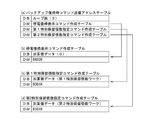
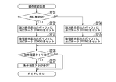
バックアップ復帰処理(S24)では、図12に示すように、まずバックアップ復帰時コマンド送信処理(M_MKINFO)をコールする(Sj1)。このバックアップ復帰時コマンド送信処理(Sj1)では、図19に示すように、まずバックアップ復帰時コマンド送信アドレステーブルを選択し(S101)、そのコマンド送信アドレステーブルに基づいて、既に説明した図17の送信コマンドテーブル選択処理(S102)を実行する。本実施形態のバックアップ復帰時コマンド送信アドレステーブルは、図21(a)に示すように、ループ数が3に設定されると共に、停電復帰表示コマンド作成テーブル、第1特別保留個数指定コマンド作成テーブル、第2特別保留個数指定コマンド作成テーブルの3種類のコマンド作成テーブルのアドレスが設定されている。 In the backup restoration process (S24), as shown in FIG. 12, first, the backup restoration command transmission process (M_MKINFO) is called (Sj1). In this backup restoration command transmission process (Sj1), as shown in FIG. 19, first, the backup restoration command transmission address table is selected (S101), and based on the command transmission address table, the transmission of FIG. 17 already described above is performed. The command table selection process (S102) is executed. As shown in FIG. 21A, in the backup return command transmission address table of the present embodiment, the number of loops is set to 3, the power failure recovery display command creation table, the first special hold quantity designation command creation table, and the like. The addresses of the three types of command creation tables of the second special hold quantity specification command creation table are set.
上述したように、送信コマンドテーブル選択処理(図17)では、指定されたコマンド送信アドレステーブル(ここでは図21(a))からループ数を取得した後(S81)、コマンド作成テーブルのアドレスを指定して(S82)、その指定されたコマンド作成テーブルに基づいてコマンドデータ作成処理(図18)を実行する処理(S83)をループ数だけ繰り返すようになっている。 As described above, in the transmission command table selection process (FIG. 17), after acquiring the number of loops from the designated command transmission address table (here, FIG. 21 (a)) (S81), the address of the command creation table is specified. Then (S82), the process (S83) of executing the command data creation process (FIG. 18) based on the designated command creation table is repeated for the number of loops.
またコマンドデータ作成処理(図18)では、指定されたコマンド作成テーブルからコマンドデータと加算値とを取得すると共に、そのコマンドデータに加算値を加算することによりコマンドデータを作成し(S91)、送信する(S92)。図21(b)に示す停電復帰表示コマンド作成テーブルでは、加算値が0に、コマンドデータはBA03Hに夫々設定されているため、送信される停電復帰表示コマンドはBA03Hとなる。一方、図21(c)に示す第1特別保留個数指定コマンドテーブルでは、加算値として第1特別保留個数ワークの値が設定され、コマンドデータはB001Hに設定されている。第1特別保留個数ワークの値は0〜4の何れかであるため、送信される第1特別保留個数指定コマンドは、第1特別保留個数0〜4に対応してB001H〜B005Hの何れかとなる。同様に、図21(d)に示す第2特別保留個数指定コマンドテーブルでは、加算値として第2特別保留個数ワークの値が設定され、コマンドデータはB101Hに設定されているため、送信される第2特別保留個数指定コマンドは、第2特別保留個数0〜4に対応してB101H〜B105Hの何れかとなる。
Further, in the command data creation process (FIG. 18), the command data and the added value are acquired from the specified command creation table, and the command data is created by adding the added value to the command data (S91) and transmitted. (S92). In the power failure recovery display command creation table shown in FIG. 21B, since the added value is set to 0 and the command data is set to BA03H, the power failure recovery display command to be transmitted is BA03H. On the other hand, in the first special hold quantity designation command table shown in FIG. 21 (c), the value of the first special hold quantity work is set as an addition value, and the command data is set to B001H. Since the value of the first special hold quantity work is any of 0 to 4, the transmitted first special hold quantity specification command is any of B001H to B005H corresponding to the first
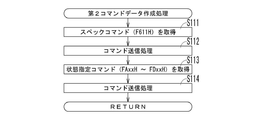
S102の送信コマンドテーブル選択処理に続いては、第2コマンドデータ作成処理(S103)を実行する。この第2コマンドデータ作成処理(S103)では、図20に示すように、まずスペックコマンド(F611H)のデータを取得し(S111)、送信する(S112)。そして、1又は複数種類の状態指定コマンド(FAxxH〜FDxxH)のデータを取得し(S113)、送信する(S114)。 Following the transmission command table selection process in S102, the second command data creation process (S103) is executed. In this second command data creation process (S103), as shown in FIG. 20, first, the data of the spec command (F611H) is acquired (S111) and transmitted (S112). Then, the data of one or a plurality of types of state designation commands (FAxxH to FDxxH) are acquired (S113) and transmitted (S114).
以上の第2コマンドデータ作成処理(S103)に続いては、第1,第2特別図柄が変動中であるか否かを判定し(S104)、変動中でなければ(S104:Yes)、客待ち中コマンド(BA04H)のデータを取得し(S105)、送信する(S106)。 Following the above second command data creation process (S103), it is determined whether or not the first and second special symbols are changing (S104), and if not (S104: Yes), the customer. The data of the waiting command (BA04H) is acquired (S105) and transmitted (S106).
以上のように、バックアップ復帰時コマンド送信処理(Sj1)により、BA03H(停電復帰表示コマンド)、B0xxH(第1特別保留個数指定コマンド)、B1xxH(第2特別保留個数指定コマンド)、F611H(スペックコマンド)、FAxxH〜FDxxH(状態指定コマンド)が順次送信され、更に図柄変動中でなければBA04H(客待ち中コマンド)が送信される。 As described above, BA03H (power failure recovery display command), B0xxH (first special hold quantity specification command), B1xxH (second special hold quantity designation command), F611H (spec command) by the backup recovery command transmission process (Sj1). ), FAxxH to FDxxH (state specification command) are sequentially transmitted, and BA04H (customer waiting command) is transmitted if the symbol is not changing.
図12に戻って説明を続ける。以上のバックアップ復帰時コマンド送信処理(Sj1)に続いては、領域内RAMにおけるバックアップフラグのアドレスをHLレジスタにセットし(Sj2)、領域内RAMにおける入賞口エラー検出タイマ3のアドレスからバックアップフラグのアドレスを引いて1を加えることにより得られた値をBレジスタにセットする(Sj3)と共に、0クリア処理をコールする(Sj4)。本実施形態では、領域内RAMの先頭が設定値ワーク領域、その次がバックアップフラグワーク領域となっており、そのバックアップフラグワーク領域の次から入賞口エラー検出タイマ3ワーク領域までの間が、エラー関連のワーク領域となっている。従って、上記Sj2〜Sj4により、領域内RAMにおけるバックアップフラグワーク領域と、それに続くエラー関連のワーク領域とが0クリアされる。このように、バックアップ復帰時であっても、エラー関連のワーク領域だけは0クリアすることで、電断前のエラー情報を持ち越さないようになっている。
The explanation will be continued by returning to FIG. Following the above backup return command transmission process (Sj1), the address of the backup flag in the area RAM is set in the HL register (Sj2), and the backup flag is set from the address of the winning opening
設定確認分岐判定処理(S22)に戻って説明を続ける。図12のSh2において、Sh1で得られた値が0であれば(ゼロフラグ=1)、即ちW(1,1,0)であれば、「設定確認」の処理態様が選択され、SYSTEM_1100(バックアップ復帰処理(S24))へとジャンプすることなく、次の設定確認処理S23へと移行する。 The explanation will be continued by returning to the setting confirmation branch determination process (S22). In Sh2 of FIG. 12, if the value obtained in Sh1 is 0 (zero flag = 1), that is, W (1,1,0), the processing mode of "setting confirmation" is selected, and SYSTEM_1100 (backup). The process proceeds to the next setting confirmation process S23 without jumping to the return process (S24)).
設定確認処理(S23)では、図12に示すように、まず設定確認期間が開始したことを示すE021H(設定確認中コマンドデータ)をDEレジスタに格納し(Si1)、コマンド送信処理(Si2)によってそのコマンドデータを送信する。演出制御基板83aが設定確認中コマンド(E021H)を受信すると、例えば液晶表示手段66には「設定確認中」等の表示が行われる(図44)。
In the setting confirmation process (S23), as shown in FIG. 12, first, E021H (command data during setting confirmation) indicating that the setting confirmation period has started is stored in the DE register (Si1), and the command transmission process (Si2) is performed. Send the command data. When the
また、領域内RAMの設定値ワーク領域から設定値データを取得し、Cレジスタに格納する(Si3)。なお、この時点では既にRAM異常判定処理(S19)が行われているため、設定変更処理(S17)におけるS63,S64(図15)のような処理を実行する必要はない。 Further, the set value data is acquired from the set value work area of the RAM in the area and stored in the C register (Si3). Since the RAM abnormality determination process (S19) has already been performed at this point, it is not necessary to execute the processes such as S63 and S64 (FIG. 15) in the setting change process (S17).
続いて、Si4〜Si15の処理を、Si7の条件を満たしてSYSTEM_1060(Si16)にジャンプするまで繰り返し実行する。このSi4〜Si15のループ処理では、まず第1電源異常チェック処理(図11)を実行し(Si4)、入力ポート1(P_INPT1)のデータ(図13)をAレジスタに入力する(Si5)。そして、Aレジスタの値とマスクデータ“00000001B”との論理積(AND)を求めることにより、設定変更操作手段93のON/OFF信号に対応する第0ビット以外のビットをマスクし、Aレジスタをそのマスク後のデータに更新する(Si6)。これにより、設定変更操作手段93がON(入力ポートの第0ビットが1)の場合にはAレジスタの値が“00000001B”となり、設定変更操作手段93がOFF(入力ポートの第0ビットが0)の場合にはAレジスタの値が“00000000B”となってゼロフラグに1がセットされる。 Subsequently, the processes of Si4 to Si15 are repeatedly executed until the conditions of Si7 are satisfied and the jump to SYSTEM_1060 (Si16) is performed. In the loop processing of Si4 to Si15, first, the first power supply abnormality check processing (FIG. 11) is executed (Si4), and the data (FIG. 13) of the input port 1 (P_INPT1) is input to the A register (Si5). Then, by obtaining the logical product (AND) of the value of the A register and the mask data "00000001B", the bits other than the 0th bit corresponding to the ON / OFF signal of the setting change operation means 93 are masked, and the A register is set. The data after masking is updated (Si6). As a result, when the setting change operation means 93 is ON (the 0th bit of the input port is 1), the value of the A register becomes "00000001B", and the setting change operation means 93 is OFF (the 0th bit of the input port is 0). In the case of), the value of the A register becomes "0000000000B" and 1 is set in the zero flag.
そして、ゼロフラグが1の場合、即ち設定変更操作手段93がOFFの場合には、Si4〜Si15のループ処理を抜けてSYSTEM_1060(Si16)にジャンプするが、ゼロフラグが0の場合、即ち設定変更操作手段93がONの場合には次のSi8に移行する(Si7)。 Then, when the zero flag is 1, that is, when the setting change operation means 93 is OFF, the loop processing of Si4 to Si15 is exited and the jump is made to SYSTEM_1060 (Si16), but when the zero flag is 0, that is, the setting change operation means. When 93 is ON, the process proceeds to the next Si8 (Si7).
続くSi8では、“00000010B”をAレジスタに入力し、このAレジスタの値を外部出力ポート2(P_GAIBU2)に出力する(Si9)。これにより、設定確認中信号がホールコンピュータに出力される。 In the subsequent Si8, "00000010B" is input to the A register, and the value of the A register is output to the external output port 2 (P_GAIBU2) (Si9). As a result, the setting confirmation signal is output to the hall computer.
そして、設定表示データテーブル(図15(c))の先頭アドレスをHLレジスタにセットし(Si10)、Cレジスタに格納されている設定値データ(Si3参照)をAレジスタに転送し(Si11)、HLレジスタの値(設定表示データテーブルの先頭アドレス)にAレジスタの値(設定値データ)を加算して得られたアドレス(図15(c)の設定表示データテーブルにおける設定値データ0〜5の何れかに対応するアドレス)から表示パターンデータを読み出してWレジスタにセットする(Si12)。これにより、Wレジスタには、設定値データに対応する表示パターンデータ、例えば設定値データが0であれば「1」を表示するための“00000110B”が、設定値データが5であれば「6」を表示するための“01111101B”がセットされる。
Then, the start address of the setting display data table (FIG. 15 (c)) is set in the HL register (Si10), and the set value data (see Si3) stored in the C register is transferred to the A register (Si11). The address obtained by adding the value of the A register (setting value data) to the value of the HL register (starting address of the setting display data table) (setting
次に、7セグ表示部97aに対応するコモンC4(図7)をONにするコモンデータ“00010000B”をAレジスタにセットし(Si13)、Aレジスタの値をLEDコモンポート(図7)に、Wレジスタの値をLEDデータポート2(図7)に夫々出力する(Si14)。これにより、設定値データ(0〜5の何れか)に対応して「1」〜「6」の何れかが設定表示手段94、即ち性能情報表示手段97の7セグ表示部97aに表示される。
Next, the common data "00010000B" for turning on the common C4 (FIG. 7) corresponding to the 7-
このように、設定確認処理S23では設定値ワークから取得した設定値データに基づいて設定表示用データを作成するため、設定確認期間中に設定表示手段94に表示される値(例えば「1」〜「6」の何れか)は、設定変更期間中とは異なり、その時点の確定した設定情報である。従って、設定確認期間中に設定表示手段94に表示される「1」〜「6」には例えば「.(ドット)」は付加されない。 In this way, in the setting confirmation process S23, since the setting display data is created based on the setting value data acquired from the setting value work, the values displayed on the setting display means 94 during the setting confirmation period (for example, "1" to "1" to " (Any of "6") is the fixed setting information at that time, unlike the setting change period. Therefore, for example, ". (Dot)" is not added to "1" to "6" displayed on the setting display means 94 during the setting confirmation period.
Si14が終了すると、SYSTEM_1050にジャンプし、Si4以降の処理を再度実行する。そして、Si7でゼロフラグが1、即ち設定変更操作手段93がOFFであると判定されると、設定確認期間を終了し、このループ処理を抜けてSYSTEM_1060にジャンプして、Si16以降の処理を実行する。即ち、WAレジスタの値同士で排他的論理和(XOR)を求め、得られた値でWAレジスタの値を更新することにより、WAレジスタをクリアする(Si16)と共に、そのWAレジスタのうちのAレジスタの値をLEDコモンポート(図7)に、Wレジスタの値をLEDデータポート2(図7)に夫々出力することにより(Si17)、設定表示手段94への設定情報の表示を停止する。 When Si14 is completed, the process jumps to SYSTEM_1050 and the processing after Si4 is executed again. Then, when it is determined in Si7 that the zero flag is 1, that is, the setting change operation means 93 is OFF, the setting confirmation period ends, the loop processing is exited, the jump to SYSTEM_1060 is performed, and the processing after Si16 is executed. .. That is, the exclusive OR (XOR) is obtained between the values of the WA registers, and the value of the WA register is updated with the obtained value to clear the WA register (Si16) and A of the WA registers. By outputting the register value to the LED common port (FIG. 7) and the W register value to the LED data port 2 (FIG. 7) (Si17), the display of the setting information on the setting display means 94 is stopped.
また、Aレジスタの値を外部出力ポート2(P_GAIBU2)に出力することにより(Si18)、設定確認中信号の出力を停止する。そして、Eレジスタの値をインクリメントし(Si19)、コマンド送信処理(Si20)によってそのコマンドデータを送信する。Si19の実行時点では、DEレジスタにはE021Hがセットされているから(Si1参照)、Si19でEレジスタをインクリメントした上でコマンド送信処理(Si20)を実行することにより、演出制御基板83aに対してE022H(設定確認終了コマンド)が送信される。なお、演出制御基板83aが設定確認終了コマンド(E022H)を受信すると、例えば液晶表示手段66の「設定確認中」等の表示が終了する。
Further, by outputting the value of the A register to the external output port 2 (P_GAIBU2) (Si18), the output of the setting confirmation signal is stopped. Then, the value of the E register is incremented (Si19), and the command data is transmitted by the command transmission process (Si20). Since E021H is set in the DE register at the time of execution of Si19 (see Si1), the command transmission process (Si20) is executed after incrementing the E register in Si19 to the
このように本実施形態では、電源投入時に設定変更操作手段93がON、RAMクリアスイッチ92がOFFで且つ扉開放中である場合(W(1,1,0)には、設定変更操作手段93がOFFに切り替えられるまでの設定確認期間中、設定表示手段94にその時点の設定情報(例えば1〜6の何れか)が表示される。
As described above, in the present embodiment, when the setting change operation means 93 is ON when the power is turned on, the RAM
以上の設定確認処理(S23)に続いては、既に説明したバックアップ復帰処理(S24)を実行する。 Following the above setting confirmation process (S23), the backup restoration process (S24) already described is executed.
以上のS15〜S24が終了すると、図10の処理に移行し、タイマ割込みが例えば4ms周期で実行されるようにCTC(Counter Timer Circuit)の設定を行い(S25)、発射許可信号をONに設定する(S26)と共に、演出制御基板83aに対して遊技開始コマンド(BA77H)を送信する(S27)。
When the above steps S15 to S24 are completed, the process proceeds to the process shown in FIG. 10, the CTC (Counter Timer Circuit) is set so that the timer interrupt is executed at a cycle of, for example, 4 ms (S25), and the launch permission signal is set to ON. (S26), and a game start command (BA77H) is transmitted to the
そして、全レジスタを退避させ(S28)、領域外プログラムである動作確認設定処理(S29)を呼び出して実行した後、全レジスタを復帰させる(S30)。動作確認設定処理(S29)では、図22に示すように、性能表示手段95の動作確認中であるか否かを示す動作確認フラグをON(動作確認中)にする(S121)と共に、動作確認時間を計時するための動作確認タイマに初期値(例えば5秒に対応する値)をセットする(S122)。なお、これら動作確認フラグ、動作確認タイマは領域外RAMに記憶される。性能表示手段95の動作確認については後述する。 Then, all the registers are saved (S28), the operation check setting process (S29), which is an out-of-area program, is called and executed, and then all the registers are restored (S30). In the operation confirmation setting process (S29), as shown in FIG. 22, the operation confirmation flag indicating whether or not the operation of the performance display means 95 is being confirmed is turned ON (operation is being confirmed) (S121), and the operation is confirmed. An initial value (for example, a value corresponding to 5 seconds) is set in the operation confirmation timer for timing the time (S122). These operation confirmation flags and operation confirmation timers are stored in the out-of-area RAM. The operation check of the performance display means 95 will be described later.
続いてメインループ処理(S31〜S36)を実行する。このメインループ処理では、割込みを禁止し(S31)、各種乱数を更新し(S32)、全レジスタをスタック領域に退避させ(S33)、性能表示集計除算処理(S34)を実行した後、全レジスタを復帰させて(S35)割込みを許可する(S36)という一連の処理を繰り返し実行する。これにより、例えば4ms周期でタイマ割込み処理が呼び出され、実行される。 Subsequently, the main loop processing (S31 to S36) is executed. In this main loop processing, interrupts are prohibited (S31), various random numbers are updated (S32), all registers are saved in the stack area (S33), performance display aggregation division processing (S34) is executed, and then all registers are executed. Is restored (S35), and a series of processes of permitting interrupts (S36) are repeatedly executed. As a result, for example, the timer interrupt process is called and executed at a cycle of 4 ms.
ここで、性能表示集計除算処理(S34)は、性能表示手段95に表示するベース値(所定情報)を算出するもので、所定時点からアウト個数が所定個数(例えば60000個)に達するまでの単位期間中に、その単位期間中における「低確率状態での払い出し個数」と「低確率状態でのアウト個数」とをカウントし、前者を後者で除算することにより第1ベース値を算出する。第2ベース値については、前回の単位期間における最終の第1ベース値をそのまま用いる。 Here, the performance display aggregation division process (S34) calculates the base value (predetermined information) to be displayed on the performance display means 95, and is a unit from a predetermined time point until the number of outs reaches a predetermined number (for example, 60,000). During the period, the "number of payouts in the low probability state" and the "number of outs in the low probability state" during the unit period are counted, and the first base value is calculated by dividing the former by the latter. As for the second base value, the final first base value in the previous unit period is used as it is.
図23は、以上説明した電源投入処理において主制御基板82aから演出制御基板83aに対して送信される主なコマンドとその送信順序とを、「設定変更」、「RAMクリア」、「設定確認」、「バックアップ復帰」、「RAM異常」の5種類の処理態様毎に示したものである。この図23より明らかなように、「設定変更」における設定変更中コマンド(BA5AH)及び設定変更完了コマンド(BA09H)、「RAMクリア」におけるRAMクリアコマンド(BA02H)、「設定確認」における設定確認中コマンド(E021H)及び設定確認終了コマンド(E022H)、「RAM異常」における電源再投入コマンド(BA07H)については各処理態様の場合にのみ送信されるが、それ以外のコマンドについては、複数の処理態様において共通に送信されるようになっている。
FIG. 23 shows “setting change”, “RAM clear”, and “setting confirmation” of the main commands transmitted from the
続いて、主制御基板82aのタイマ割込み処理(図24)について説明する。このタイマ割込み処理(図24)では、まず第2電源異常チェック処理(S131)を実行する。この第2電源異常チェック処理では、例えば図25に示すように、まず電源基板89aから送信されてくる電源異常信号を2回読み込む(S151)。そして、その2回読み込んだ電源異常信号のレベルが一致するか否かを判定し(S152)、それらのレベルが一致しない場合(S152:No)にはS151に戻り、一致する場合(S152:Yes)にはその電源異常信号がONであるか否か、即ち電源異常信号のレベルが「H」レベルであるか否かを判定する(S153)。
Subsequently, the timer interrupt processing (FIG. 24) of the
電源異常信号のレベルが「H」レベル(ON)でない場合には(S153:No)、バックアップフラグをOFF(≠5AH)に設定する(S154)と共に、電源異常確認カウンタの値をクリアし(S155)、第2電源異常チェック処理を終了する。 If the power supply abnormality signal level is not "H" level (ON) (S153: No), the backup flag is set to OFF (≠ 5AH) (S154), and the value of the power supply abnormality confirmation counter is cleared (S155). ), The second power supply abnormality check process is terminated.
一方、電源異常信号のレベルが「H」レベル(ON)である場合には(S153:Yes)、電源異常確認カウンタの値をインクリメント(+1)する(S156)と共に、インクリメント後の電源異常確認カウンタの値が例えば2に達しているか否かを判定する(S157)。そして電源異常確認カウンタの値が2未満であれば(S157:No)、そのまま第2電源異常チェック処理を終了する。 On the other hand, when the power supply abnormality signal level is "H" level (ON) (S153: Yes), the value of the power supply abnormality confirmation counter is incremented (+1) (S156), and the power supply abnormality confirmation counter after the increment is incremented (S156). It is determined whether or not the value of is reaching 2, for example (S157). If the value of the power supply abnormality confirmation counter is less than 2 (S157: No), the second power supply abnormality check process is terminated as it is.
S157で電源異常確認カウンタの値が2に達している場合には(S157:Yes)、電源異常と判断し、RAMに記憶されているデータ(遊技情報)のバックアップ処理(S158〜S161)を行う。即ち、電源異常確認カウンタの値をクリアし(S158)、発射制御信号をOFFに設定し(S159)、バックアップフラグを5AHに設定する(S160)。そして、RAMの作業領域に対して連続して8ビット加算を実行することによりチェックサムを演算し、その演算結果(SUM番地)をチェックサム値としてRAMのSUM記憶領域に保存する(S161)。 When the value of the power supply abnormality confirmation counter reaches 2 in S157 (S157: Yes), it is determined that the power supply is abnormal, and the data (game information) stored in the RAM is backed up (S158 to S161). .. That is, the value of the power supply abnormality confirmation counter is cleared (S158), the firing control signal is set to OFF (S159), and the backup flag is set to 5AH (S160). Then, a checksum is calculated by continuously executing 8-bit addition to the work area of the RAM, and the calculation result (SUM address) is saved as a checksum value in the SUM storage area of the RAM (S161).
その後、演出制御基板83a等に対して電源断コマンドを送信し(S162)、RAMのプロテクトを有効にすると共に禁止領域を無効とする(S163)。これにより、以降の処理においてRAMへのデータ書込みが禁止される。また、全ての出力ポートの出力データをクリアし(S164)、CTCに対する設定処理によってタイマ割込みを禁止した後(S165)、WDTをクリアしつつ無限ループ処理を繰り返し、電源電圧が降下してCPUが非動作状態になるのを待つ。
After that, a power off command is transmitted to the
以上の第2電源異常チェック処理(図24のS131)が終了すると、続いて遊技制御に用いられる各種タイマを管理するタイマ管理処理(S132)、各入賞手段に設けた遊技球検出手段や操作手段等の各種センサによる検出情報を管理する入力管理処理(S133)、設定値に関する異常チェックを行う設定異常チェック処理(S134)、各種エラーの発生を監視するエラー管理処理(S135)、大当たり判定乱数等の各種乱数を更新する乱数更新処理(S136)、払出制御基板90aに払出制御コマンドを送信する等の賞球管理を行う賞球管理処理(S137)を実行する。
When the above second power supply abnormality check process (S131 in FIG. 24) is completed, a timer management process (S132) for managing various timers used for game control, and a game ball detecting means and operating means provided for each winning means. Input management process (S133) that manages detection information by various sensors such as, setting abnormality check process (S134) that checks abnormalities related to set values, error management process (S135) that monitors the occurrence of various errors, jackpot judgment random numbers, etc. The random number update process (S136) for updating various random numbers in the above, and the prize ball management process (S137) for managing the prize balls such as transmitting a payout control command to the
ここで、設定異常チェック処理(S134)では、例えば図26に示すように、まず設定エラーフラグが5AH(設定エラー中)であるか否かを判定し(S171)、5AHであれば(S171:Yes)そのまま設定異常チェック処理を終了する。また設定エラーフラグが5AHでない場合には(S171:No)、設定値ワーク領域の設定値データが0〜5の範囲内か否かを判定し(S172)、設定値データが0〜5の範囲内であれば(S172:Yes)そのまま設定異常チェック処理を終了する。 Here, in the setting abnormality check process (S134), for example, as shown in FIG. 26, it is first determined whether or not the setting error flag is 5AH (during a setting error) (S171), and if it is 5AH (S171:). Yes) The setting error check process ends as it is. If the setting error flag is not 5AH (S171: No), it is determined whether or not the set value data in the set value work area is within the range of 0 to 5 (S172), and the set value data is in the range of 0 to 5. If it is within (S172: Yes), the setting abnormality check process is terminated as it is.
設定エラーフラグが5AHでなく(S171:No)、設定値データが0〜5の範囲内にない場合には(S172:No)、設定エラーフラグに5AHをセットする(S173)と共に、演出制御基板83aに対して設定値異常コマンド(0E33H)を送信し(S174)、設定異常チェック処理を終了する。なお、演出制御基板83aが設定値異常コマンド(0E33H)を受信すると、例えば液晶表示手段66には「RAM異常です 係員を呼んでください」等の表示が行われる。
If the setting error flag is not 5AH (S171: No) and the set value data is not within the range of 0 to 5 (S172: No), the setting error flag is set to 5AH (S173) and the effect control board. A setting value error command (0E33H) is transmitted to 83a (S174), and the setting error check process is terminated. When the
図24の賞球管理処理(S137)に続いては、普通図柄管理処理(S138)、普通電動役物管理処理(S139)、特別図柄管理処理(S140)、特別電動役物管理処理(S141)を実行する。 Following the prize ball management process (S137) of FIG. 24, a normal symbol management process (S138), a normal electric accessory management process (S139), a special symbol management process (S140), and a special electric accessory management process (S141). To execute.
普通図柄管理処理(S138)は、普通図柄表示手段51による普通図柄の変動を管理するもので、普通図柄始動手段61が遊技球を検出することに基づいて、当たり判定乱数値等の普通乱数情報を取得すると共にその普通乱数情報を予め定められた上限保留個数(例えば4個)を限度として先入れ先出し式の記憶領域に記憶し、普通図柄表示手段51が変動表示可能な状態となり且つ1個以上の普通乱数情報が記憶されていること(普通保留個数が1以上であること)を条件に、普通乱数情報の待ち行列からその先頭の当たり判定乱数値を取り出し、その当たり判定乱数値が予め定められた当たり判定値と一致するか否かに応じて当たり/はずれの判定(当たり判定)を行うと共に、その当たり判定結果に基づいて普通図柄の変動後の停止図柄及び変動時間を選択し、普通図柄表示手段51による普通図柄の変動を行うようになっている。 The normal symbol management process (S138) manages the fluctuation of the normal symbol by the normal symbol display means 51, and based on the normal symbol starting means 61 detecting the game ball, the normal random number information such as the hit determination random number value. And the ordinary random number information is stored in the first-in, first-out storage area up to a predetermined upper limit reserved number (for example, 4), and the ordinary symbol display means 51 is in a state where variable display is possible and one or more. On condition that the normal random number information is stored (normally the number of pending numbers is 1 or more), the first hit judgment random number value is taken out from the normal random number information queue, and the hit judgment random number value is predetermined. The hit / miss judgment (hit judgment) is performed according to whether or not it matches the hit judgment value, and the stop symbol and the fluctuation time after the change of the normal symbol are selected based on the hit judgment result, and the normal symbol is selected. The display means 51 is used to change the normal symbol.
また、普通電動役物管理処理(S139)は、普通利益状態を管理するもので、S138の当たり判定結果が当たりとなることに基づいて普通図柄表示手段51の変動後の停止図柄が当たり態様となった場合に、第2特別図柄始動手段63の開閉部78を所定の開閉パターンに従って開状態に変化させる普通利益状態を発生させるようになっている。
Further, the ordinary electric accessory management process (S139) manages the ordinary profit state, and the stop symbol after the change of the ordinary symbol display means 51 is the hit mode based on the hit determination result of S138. When this happens, a normal profit state is generated in which the opening / closing
特別図柄管理処理(S140)は、第1,第2特別図柄表示手段53,54による第1,第2特別図柄の変動を管理する処理である。この特別図柄管理処理では、例えば図27に示すように、まず前回の割込み時から今回までの間に第1特別図柄始動手段62と第2特別図柄始動手段63との何れかに遊技球が入賞したか否か(遊技球を検出したか否か)を判定する(S181,S183)。そして、第1特別図柄始動手段62への入賞があった場合には第1始動入賞処理(S182)を、第2特別図柄始動手段63への入賞があった場合には第2始動入賞処理(S184)を夫々実行する。 The special symbol management process (S140) is a process of managing changes in the first and second special symbols by the first and second special symbol display means 53 and 54. In this special symbol management process, for example, as shown in FIG. 27, a game ball wins a prize in either the first special symbol starting means 62 or the second special symbol starting means 63 between the time of the previous interruption and the present time. It is determined whether or not (whether or not a game ball has been detected) has been determined (S181, S183). Then, when there is a prize in the first special symbol starting means 62, the first start winning process (S182) is performed, and when there is a prize in the second special symbol starting means 63, the second start winning process (S182) is performed. S184) is executed respectively.
第1,第2始動入賞処理(S182,S184)では、例えば大当たり判定乱数値、大当たり図柄乱数値、その他の乱数値よりなる第1,第2特別乱数情報を予め定められた保留上限数(例えば各4個)を限度として先入れ先出し式の記憶領域に記憶すると共に、増加後の第1,第2特別保留個数に基づいて演出制御基板83aに対して保留加算コマンドを送信する。また第1,第2始動入賞処理(S182,S184)では、第1,第2特別図柄始動手段62,63への遊技球入賞時に取得した第1,第2特別乱数情報について、例えばその取得時に、その第1,第2特別乱数情報に含まれる大当たり判定乱数値が大当たり判定値と一致するか否か(大当たりか否か)等について先読み判定を実行可能となっている。この先読み判定の結果は例えば保留加算コマンドによって演出制御基板83a等に伝達される。
In the first and second start winning processes (S182 and S184), for example, the first and second special random number information consisting of the jackpot determination random number value, the jackpot symbol random number value, and other random number values is stored in a predetermined upper limit number (for example). A maximum of 4 each) is stored in the first-in, first-out storage area, and a hold addition command is transmitted to the
続いて、第1,第2特別図柄の変動に関する状況を示す図柄変動ステータスを判定し(S185)、図柄変動ステータスが00H又は01H(変動待機中)であれば特別図柄変動開始処理(S186)を、02H(変動中)であれば特別図柄変動中処理(S187)を、03H(確認中)であれば特別図柄確認時間中処理(S188)を、夫々実行する。 Subsequently, the symbol variation status indicating the status regarding the variation of the first and second special symbols is determined (S185), and if the symbol variation status is 00H or 01H (waiting for variation), the special symbol variation start process (S186) is performed. , 02H (during change), special symbol change processing (S187) is executed, and 03H (confirmation), special symbol confirmation time processing (S188) is executed.
図柄変動ステータスが00H又は01H(変動待機中)の場合に実行する特別図柄変動開始処理(S186)では、例えば図28に示すように、第2特別保留個数が0であるか否かを判定し(S191)、第2特別保留個数が0でない場合には(S191:No)、第2特別保留個数を1減算する(S191a)と共に、演出制御基板83aに対して保留減算コマンドを送信する(S193)。
In the special symbol change start process (S186) executed when the symbol change status is 00H or 01H (waiting for change), for example, as shown in FIG. 28, it is determined whether or not the second special hold quantity is 0. (S191), if the second special hold quantity is not 0 (S191: No), the second special hold quantity is subtracted by 1 (S191a), and a hold subtraction command is transmitted to the
また、S191で第2特別保留個数が0である場合には(S191:Yes)、第1特別保留個数が0であるか否かを判定し(S192)、第1特別保留個数が0でない場合には(S192:No)、第1特別保留個数を1減算する(S192a)と共に、演出制御基板83aに対して保留減算コマンドを送信する(S193)。以上の処理により、第1特別図柄の図柄変動よりも第2特別図柄の図柄変動の方が優先して実行される。
Further, when the second special hold quantity is 0 in S191 (S191: Yes), it is determined whether or not the first special hold quantity is 0 (S192), and when the first special hold quantity is not 0. (S192: No), the first special hold quantity is subtracted by 1 (S192a), and a hold subtraction command is transmitted to the
また、第1,第2特別保留個数が共に0であれば(S192:Yes)、図柄変動ステータスが00Hであるか否かを判定し(S202)、00Hでなければ(S202:No)、図柄変動ステータスを00Hに変更する(S203)と共に、演出制御基板83aに対して客待ち中コマンド(BA04H)を送信し(S204)、特別図柄変動開始処理を終了する。図柄変動ステータスが00Hであれば(S202:Yes)、即ち変動待機中になった後にS203,S204を既に実行済みの場合には、S203,S204はスキップする。このように、第1,第2特別図柄の変動が終了し且つその時点で第1,第2特別保留個数が共に0である場合に客待ち中コマンド(BA04H)が送信される。
Further, if the first and second special reserved numbers are both 0 (S192: Yes), it is determined whether or not the symbol variation status is 00H (S202), and if it is not 00H (S202: No), the symbol Along with changing the variation status to 00H (S203), a customer waiting command (BA04H) is transmitted to the
S193に続いては、設定エラーフラグが5AH(設定エラー中)であるか否かを判定し(S194)、設定エラーフラグが5AH(設定エラー中)でなければ大当たり判定処理を実行し(S194:No→S195)、設定エラーフラグが5AH(設定エラー中)であれば大当たり判定処理(S195)をスキップする(S194:Yes)。大当たり判定処理(S195)は、乱数抽選により大当たり/はずれの判定(大当たり判定)を行うもので、図29に示す処理を実行することにより、第1特別乱数情報又は第2特別乱数情報の待ち行列からその先頭の大当たり判定乱数値を取り出し、その大当たり判定乱数値が予め定められた大当たり判定値と一致するか否かに応じて大当たり/はずれの判定を行うようになっている。 Following S193, it is determined whether or not the setting error flag is 5AH (during setting error) (S194), and if the setting error flag is not 5AH (during setting error), the jackpot determination process is executed (S194: No → S195), if the setting error flag is 5AH (during setting error), the jackpot determination process (S195) is skipped (S194: Yes). The jackpot determination process (S195) determines jackpot / miss (big hit determination) by random number lottery, and by executing the process shown in FIG. 29, a queue of first special random number information or second special random number information is executed. The jackpot determination random number value at the beginning is taken out from, and the jackpot / loss determination is performed according to whether or not the jackpot determination random number value matches a predetermined jackpot determination value.
ここで、大当たり判定値は、図30に示すように大当たり判定乱数値のとり得る範囲(例えば0〜65535)のうちの所定範囲(例えば10001〜10217、又は10001〜12184)に定められており、大当たり判定乱数値がその所定範囲内にあれば大当たり、所定範囲内になければはずれとなる。また、大当たり確率には低確率と高確率とがあり、高確率の場合には低確率の場合に比べて大当り判定値の範囲(所定範囲)が広くなる。本実施形態では、低確率のときの大当たり判定値の範囲(例えば10001〜10217)と、高確率のときの大当たり判定値の範囲(例えば10001〜12184)とは、それらの下限値が共通で、上限値が異なっている。従って、低確率のときの大当たり判定値の範囲は、高確率のときの大当たり判定値の範囲に含まれている。 Here, as shown in FIG. 30, the jackpot determination value is defined in a predetermined range (for example, 10001 to 10217 or 10001 to 12184) within the range (for example, 0 to 65535) in which the jackpot determination random value can be taken. If the jackpot determination random value is within the predetermined range, it is a jackpot, and if it is not within the predetermined range, it is a loss. Further, the jackpot probability includes a low probability and a high probability, and in the case of the high probability, the range (predetermined range) of the jackpot determination value becomes wider than in the case of the low probability. In the present embodiment, the range of the jackpot determination value at the time of low probability (for example, 10001 to 10217) and the range of the jackpot determination value at the time of high probability (for example, 10001 to 12184) have the same lower limit value. The upper limit is different. Therefore, the range of the jackpot determination value at the time of low probability is included in the range of the jackpot determination value at the time of high probability.
また本実施形態では、大当たり確率を6段階(設定1〜6)に変更可能であるため、設定1〜6に応じて大当たり判定値の範囲の下限値と上限値とのうちの上限値を異ならせている。即ち図31の大当たり判定テーブルに示すように、大当たり判定値の範囲の下限値と上限値(低確率及び高確率)とについて夫々基準値(第1情報)を設定すると共に、その基準上限値(低確率及び高確率)に対する加算値(低確率及び高確率)(差分値、第2情報)を設定1〜6毎に設定している。ここで、基準値を表現するには夫々2バイト必要であるのに対し、低確率及び高確率に対応する加算値(低確差分値、高確差分値)については1バイトで表現できる場合もあるため(本実施形態の場合は低確率に対応する加算値については全て1バイトで表現可能)、大当たり判定値の範囲の下限値及び上限値(低確率及び高確率)を設定1〜6毎にそのままの値(各2バイト)で記憶する場合と比較して記憶容量を抑制できる。
Further, in the present embodiment, since the jackpot probability can be changed in 6 stages (
なお図31の例では、設定1〜6の場合の大当たり確率(低確率)が夫々約1/300,1/280,1/260,1/240,1/220,1/200、同じく大当たり確率(高確率)が夫々約1/30,1/28,1/26,1/24,1/22,1/20となっている。また図31の例では、設定1に対応する加算値は低確、高確共に0であり、基準上限値がそのまま設定1の場合の上限値となっているから、設定1に対応する加算値については記憶する必要はない。
In the example of FIG. 31, the jackpot probabilities (low probabilities) in the cases of
大当たり判定処理(図29)の処理手順を具体的に説明すると、まず大当たり判定乱数値を、大当たり判定値の基準下限値(図31では10000)と比較し(S211)、例えば大当たり判定乱数値が基準下限値以下(S211:Yes)であれば「はずれ」となり、そのまま大当たり判定処理を終了する。 To specifically explain the processing procedure of the jackpot determination process (FIG. 29), first, the jackpot determination random number value is compared with the reference lower limit value (10000 in FIG. 31) of the jackpot determination value (S211), for example, the jackpot determination random number value is If it is equal to or less than the reference lower limit value (S211: Yes), the result is “missing” and the jackpot determination process is terminated as it is.
S211で大当たり判定乱数値が基準下限値よりも大であれば(S211:No)、大当たり確率が高確率となる確変状態中であるか否かを判定し(S212)、確変状態中であれば(S212:Yes)、高確の基準上限値(図31では12185)に、その時点の設定値(設定1〜6の何れか)に対応する高確の加算値を加算して上限値を算出し(S214)、確変状態中でなければ(S212:No)、低確の基準上限値(図31では10218)に、その時点の設定値(設定1〜6の何れか)に対応する低確の加算値を加算して上限値を算出する(S213)。これにより、例えば設定1で低確中の上限値は10218(=10218+0)となり、例えば設定3で高確中の上限値は12521(=12185+336)となる。
If the jackpot determination random value is larger than the reference lower limit value in S211 (S211: No), it is determined whether or not the jackpot probability is in a probabilistic state with a high probability (S212), and if it is in a probabilistic state. (S212: Yes), the upper limit is calculated by adding the high-probability addition value corresponding to the set value (any of
そして、大当たり判定乱数値を、算出した上限値と比較し(S215)、例えば大当たり判定乱数値が上限値以下(S215:Yes)であれば「大当たり」となり、大当たり判定フラグに大当たりを示す“5AH”をセットして(S216)大当たり判定処理を終了する。一方、大当たり判定乱数値が上限値よりも大(S215:No)であれば「はずれ」となり、そのまま大当たり判定処理を終了する。 Then, the jackpot determination random number value is compared with the calculated upper limit value (S215). For example, if the jackpot determination random number value is equal to or less than the upper limit value (S215: Yes), it becomes a "big hit" and the jackpot determination flag indicates "5AH". "(S216) to end the jackpot determination process. On the other hand, if the jackpot determination random value is larger than the upper limit value (S215: No), the result is "missing" and the jackpot determination process ends as it is.
なおこのとき、大当たり判定フラグの値は、前回の図柄変動で大当たり態様となった場合でも、例えば大当たり遊技の開始時にクリアされるため、この「はずれ」の場合の大当たり判定フラグは必ず“00H”となっている。ここで、以上説明した大当たり判定処理(図28のS195)は、上述したように設定エラー(設定エラーフラグが5AH)の場合には実行されないため、設定エラーの場合の大当たり判定フラグは必ず“00H”(はずれ)となる。 At this time, the value of the jackpot determination flag is cleared at the start of the jackpot game, for example, even if the jackpot mode is changed due to the previous symbol change, so the jackpot determination flag in the case of this "missing" is always "00H". It has become. Here, since the jackpot determination process (S195 in FIG. 28) described above is not executed in the case of a setting error (setting error flag is 5AH) as described above, the jackpot determination flag in the case of a setting error is always "00H". "(Out of place).
特別図柄変動開始処理(図28)に戻って説明を続ける。S194,S195の処理に続いては、第1,第2特別図柄の変動後の停止図柄を選択する特別停止図柄選択処理(S196)、演出図柄80の変動パターンを選択する変動パターン選択処理(S197)を実行する。 The explanation will be continued by returning to the special symbol change start processing (FIG. 28). Following the processes of S194 and S195, a special stop symbol selection process (S196) for selecting the stop symbol after the change of the first and second special symbols, and a variation pattern selection process (S197) for selecting the variation pattern of the effect symbol 80. ) Is executed.
変動パターン選択処理(S197)では、例えば図32に示すように、まず設定エラーフラグが5AH(設定エラー中)であるか否かを判定する(S221)。そして設定エラーフラグが5AH(設定エラー中)でなければ(S221:No)、大当たり判定フラグが5AH(大当たり)であるか否かを判定し(S222)、大当たり判定フラグが5AHでなければはずれ変動パターンテーブル(図33)を選択し(S223)、5AHであれば大当たり変動パターンテーブル(図34)を選択する(S228)。 In the variation pattern selection process (S197), for example, as shown in FIG. 32, it is first determined whether or not the setting error flag is 5AH (during a setting error) (S221). Then, if the setting error flag is not 5AH (during setting error) (S221: No), it is determined whether or not the jackpot determination flag is 5AH (big hit) (S222), and if the jackpot determination flag is not 5AH, the deviation fluctuates. The pattern table (FIG. 33) is selected (S223), and if it is 5AH, the jackpot variation pattern table (FIG. 34) is selected (S228).
はずれ変動パターンテーブル(図33)を選択した場合(S223)には、特別乱数情報(例えば第1特別図柄の場合には第1特別乱数情報)に含まれる図柄判定乱数値に基づいてはずれの種類を選択する(S224)。本実施形態では、はずれ1〜3の3種類のはずれが設けられており、はずれ変動パターンテーブル(図33)では、はずれ1の場合は変動パターンの選択率が特別保留個数(例えば第1特別図柄の場合には第1特別保留個数)に応じて変化するが設定値では変化せず、はずれ2,3の場合は変動パターンの選択率が設定値に応じて変化するが特別保留個数では変化しないようになっている。もちろん、変動パターンの選択率が特別保留個数と設定値との両方に基づいて変化するはずれを設けてもよい。
When the out-of-order fluctuation pattern table (FIG. 33) is selected (S223), the type of out-of-order is based on the symbol determination random number value included in the special random number information (for example, the first special random number information in the case of the first special symbol). Is selected (S224). In the present embodiment, three types of
そして、S224ではずれ1を選択した場合には(S225:Yes)、特別保留個数に応じて変動パターン乱数値に対応する変動パターンを選択し(S226)、はずれ2,3の何れかを選択した場合には(S225:No)、はずれの種類とその時点の設定値(設定1〜6の何れか)とに応じて変動パターン乱数値に対応する変動パターンを選択する(S227)。例えば、第1特別図柄の変動においてはずれ1を選択し、減算後の第1特別保留個数が3個の場合には、4sの通常変動パターンとノーマルリーチ変動パターンとが190:10の割合で選択される。
Then, in S224, when the
なお、図33(a)に示す第1特別図柄のはずれ変動パターンテーブルには次のような特徴がある。即ち、はずれ1の場合にはリーチを経ることなくはずれ態様となる通常変動パターンとノーマルリーチ変動パターンとが選択対象となり、しかも通常変動パターンについては特別保留個数が多いほど変動時間が短いものが選択されるようになっている。また、はずれ2,3の場合にはスーパーリーチ変動パターンのみが選択対象となり、各変動パターンの選択率が設定1と2、設定3と4、設定5と6で夫々同じ値に設定されている。また、はずれ2の場合には、設定1,2ではスーパーリーチ4の選択率が最も高く、スーパーリーチ1の選択率が最も低くなっているのに対し、設定3〜6では逆にスーパーリーチ1の選択率が最も高く、スーパーリーチ4の選択率が最も低くなっている。また、はずれ3の場合には、設定1,2ではスーパーリーチ1のみが、設定3,4ではスーパーリーチ2,3の何れかが、設定5,6ではスーパーリーチ4のみが選択対象となっている。これにより、第1特別図柄の変動に対応する演出図柄80の変動パターンの出現傾向により遊技者は設定値をある程度予測することが可能である。もちろん、各変動パターンの選択率を設定1〜6の全てで異ならせたはずれを設けてもよい。
The out-of-order variation pattern table of the first special symbol shown in FIG. 33A has the following features. That is, in the case of the
一方、図33(b)に示す第2特別図柄のはずれ変動パターンテーブルでは、はずれの種類や特別保留個数、設定値に拘わらず、最も変動時間の長い(ここでは12s)通常変動パターンのみが選択対象となっている。 On the other hand, in the outlier variation pattern table of the second special symbol shown in FIG. 33 (b), only the normal variation pattern having the longest variation time (12 s in this case) is selected regardless of the type of detachment, the number of special holdings, and the set value. It is the target.
また、大当たり変動パターンテーブル(図34)を選択した場合(S228)には、特別乱数情報(例えば第1特別図柄の場合には第1特別乱数情報)に含まれる図柄判定乱数値に基づいて大当たりの種類を選択する(S229)。本実施形態では、図34に示すように通常4R、通常6R、確変6R、確変10Rの4種類の大当たりが設けられている。そして、S229で選択した大当たりの種類とその時点の設定値(設定1〜6の何れか)とに応じて変動パターン乱数値に対応する変動パターンを選択する(S230)。例えば、第2特別図柄の変動において確変10Rを選択した場合、設定6であればスーパーリーチ1〜4変動パターンが5:70:5:120の割合で選択される。
When the jackpot fluctuation pattern table (FIG. 34) is selected (S228), the jackpot is based on the symbol determination random number value included in the special random number information (for example, the first special random number information in the case of the first special symbol). (S229). In this embodiment, as shown in FIG. 34, four types of jackpots of normal 4R, normal 6R,
なお、通常4R及び通常6Rは、大当たり遊技の終了後に例えば時短状態を発生させることとなる大当たりで、大当たり遊技中は例えば出玉ありのラウンドを夫々4ラウンド、6ラウンド行うようになっている。 It should be noted that the normal 4R and the normal 6R are big hits that cause, for example, a time saving state after the end of the big hit game, and during the big hit game, for example, rounds with balls are performed for 4 rounds and 6 rounds, respectively.
時短状態中は、例えば第1,第2特別図柄に関して第1,第2特別図柄表示手段53,54の変動時間が通常変動時間よりも短い短縮変動時間に切り換えられる他、普通図柄に関して、当たり確率が通常確率(例えば1/10)から高確率(例えば1/1.3)へ、変動時間が通常変動時間(例えば27秒)から短縮変動時間(例えば2.7秒)へ、第2特別図柄始動手段63の開閉パターンが通常開閉パターン(例えば0.2秒×1回開放)から特別開閉パターン(例えば2秒×3回開放)へ、夫々切り換えられるようになっている。なお、時短状態は大当たり遊技が終了した時点で開始し、例えば第1,第2特別図柄が所定回数(例えば50回)変動するか、それまでに次の大当たり遊技が発生した時点で終了する。 During the time saving state, for example, the fluctuation time of the first and second special symbol display means 53 and 54 for the first and second special symbols is switched to a shortened fluctuation time shorter than the normal fluctuation time, and the hit probability for the normal symbol. From the normal probability (for example, 1/10) to the high probability (for example, 1 / 1.3), the fluctuation time changes from the normal fluctuation time (for example, 27 seconds) to the shortened fluctuation time (for example, 2.7 seconds), and the second special symbol. The opening / closing pattern of the starting means 63 can be switched from a normal opening / closing pattern (for example, 0.2 seconds × 1 opening) to a special opening / closing pattern (for example, 2 seconds × 3 times opening). The time saving state starts when the jackpot game ends, and ends when, for example, the first and second special symbols fluctuate a predetermined number of times (for example, 50 times) or when the next jackpot game occurs by then.
また確変6R及び確変10Rは、大当たり遊技の終了後に例えば確変状態を発生させることとなる大当たりで、大当たり遊技中は例えば出玉ありのラウンドを夫々6ラウンド、10ラウンド行うようになっている。確変状態中は、例えば時短状態と同様の切り換えに加えて、大当たり判定値の数(範囲)が増加することにより(図30参照)、大当たり確率が低確率から高確率に切り換えられるようになっている。なお、確変状態は大当たり遊技が終了した時点で開始し、例えば次の大当たり遊技が発生した時点で終了する。
Further, the
図34(a)に示す第1特別図柄の大当たり変動パターンテーブルには次のような特徴がある。即ち、通常4Rと確変10Rの場合には、各変動パターンの選択率が設定1と2、設定3と4、設定5と6で夫々同じであるのに対し、通常6Rと確変6Rの場合には、各変動パターンの選択率が設定1〜6で全て同じとなっている。また、リーチを経ることなく大当たり態様となる通常変動大当たり変動パターンについては、通常4Rで設定1,2の何れかの場合と通常6Rの場合のみ選択対象となっている。また、全ての場合でスーパーリーチ1〜4のうちでスーパーリーチ4の選択率が最も高くなっているが、設定値によって選択率が異なる通常4R、確変10Rの場合には、設定5,6の場合についてはスーパーリーチ4に続いてスーパーリーチ2の選択率が高くなっているのに対し、それ以外の例えば設定1〜4の場合はスーパーリーチ1〜4の順に選択率が高くなっている。もちろん、各変動パターンの選択率を設定1〜6の全てで異ならせた大当たりを設けてもよい。
The jackpot fluctuation pattern table of the first special symbol shown in FIG. 34 (a) has the following features. That is, in the case of normal 4R and probability variation 10R, the selectivity of each fluctuation pattern is the same in
また、図34(b)に示す第2特別図柄の大当たり変動パターンテーブルには次のような特徴がある。即ち、通常4R、確変6R及び確変10Rの場合には、各変動パターンの選択率が設定1と2、設定3と4、設定5と6で夫々同じであるのに対し、通常6Rの場合には、各変動パターンの選択率が設定1〜6で全て同じとなっている。また、通常変動大当たり変動パターンについては、通常4Rで設定1,2の何れかの場合のみ選択対象となっている。また、全ての場合でスーパーリーチ1〜4のうちでスーパーリーチ4の選択率が最も高くなっているが、設定値によって選択率が異なる通常4R、確変6R、確変10Rの場合には、設定5,6の場合についてはスーパーリーチ4に続いてスーパーリーチ2の選択率が高くなっているのに対し、それ以外の例えば設定1〜4の場合はスーパーリーチ1〜4の順に選択率が高くなっている。これにより、第1,第2特別図柄の変動に対応する演出図柄80の変動パターンの出現傾向により遊技者は設定値をある程度予測することが可能である。
Further, the jackpot fluctuation pattern table of the second special symbol shown in FIG. 34 (b) has the following features. That is, in the case of normal 4R,
また、S221で設定エラーフラグが5AH(設定エラー中)であると判定した場合には(S221:Yes)、設定エラー用変動パターンテーブル(図35)を選択し(S231)、特別乱数情報(例えば第1特別図柄の場合には第1特別乱数情報)に含まれる図柄判定乱数値に基づいてはずれの種類を選択する(S232)。そして、S232ではずれ1を選択した場合には(S233:Yes)、特別保留個数に応じて変動パターン乱数値に対応する変動パターンを選択し(S234)、はずれ2,3の何れかを選択した場合には(S233:No)、はずれの種類に応じて変動パターン乱数値に対応する変動パターンを選択する(S235)。例えば、第1特別図柄の変動においてはずれ1を選択し、減算後の第1特別保留個数が1個の場合には、8sの通常変動パターンが選択される。
If it is determined in S221 that the setting error flag is 5AH (during a setting error) (S221: Yes), the setting error variation pattern table (FIG. 35) is selected (S231), and special random number information (for example, during setting error) is selected. In the case of the first special symbol, the type of error is selected based on the symbol determination random number value included in the first special random number information (S232). Then, in S232, when the
なお、図35に示す設定エラー用変動パターンテーブルでは、はずれ1〜3のうちのはずれ1のみが選択され、しかも通常変動パターンのみが選択対象となっており、更に第1特別図柄の変動時には特別保留個数が多いほど変動時間の短い通常変動パターンが選択され、第2特別図柄の変動時には特別保留個数に拘わらず特定の通常変動パターン(ここでは最も変動時間の長い12s)のみが選択されるようになっている。このように設定エラーの場合には、いわゆる激アツの変動パターン等が選択されることがないように、通常変動パターンのみを選択対象としている。なお同様の趣旨で、設定エラーの場合には演出制御基板83a側でも予告を出現させないようにすることが望ましい。
In the setting error variation pattern table shown in FIG. 35, only the
図28の特別図柄変動開始処理に戻って説明を続ける。以上説明した変動パターン選択処理(S197)に続いては、選択された変動パターンに対応する変動パターンコマンド、S196で選択した停止図柄に対応する停止図柄コマンドを演出制御基板83aに送信する(S198,S199)と共に、第1特別図柄又は第2特別図柄の変動を開始し(S200)、図柄変動ステータスを02H(変動中)に変更して(S201)、この特別図柄変動開始処理を終了する。
The explanation will be continued by returning to the special symbol variation start processing of FIG. 28. Following the variation pattern selection process (S197) described above, the variation pattern command corresponding to the selected variation pattern and the stop symbol command corresponding to the stop symbol selected in S196 are transmitted to the
図27の特別図柄管理処理において特別図柄変動開始処理(S186)が終了し、図柄変動ステータスが02H(変動中)になると、次回の割込み時からは特別図柄変動中処理(S187)を実行する。この特別図柄変動中処理(S187)では、例えば第1,第2特別図柄の変動開始から、S197で選択した変動パターンに対応する変動時間が経過することに基づいて、第1,第2特別図柄の変動を停止すると共に変動停止コマンドを演出制御基板83aに送信し、また図柄変動ステータスを03H(確認中)に変更する。
When the special symbol change start process (S186) is completed in the special symbol management process of FIG. 27 and the symbol change status becomes 02H (during change), the special symbol change process (S187) is executed from the next interrupt. In this special symbol changing process (S187), for example, the first and second special symbols are based on the elapse of the fluctuation time corresponding to the fluctuation pattern selected in S197 from the start of fluctuation of the first and second special symbols. The fluctuation stop command is transmitted to the
また、特別図柄変動中処理(S187)が終了して図柄変動ステータスが03H(確認中)になると、次回の割込み時からは特別図柄確認時間中処理(S188)を実行する。この特別図柄確認時間中処理(S188)では、例えば第1,第2特別図柄の変動停止から所定の確認時間(例えば500msec)が経過した場合には、図柄変動ステータスを01H(変動待機中)に変更すると共に、第1,第2特別図柄の変動に係る各種変数等を初期化し、その変動後の停止図柄が大当たり態様となった場合には、例えば大当たり遊技に係る各種変数等に初期値を設定するなど、大当たり遊技を開始するための準備処理を行う。 When the special symbol change processing (S187) ends and the symbol change status becomes 03H (confirming), the special symbol confirmation time processing (S188) is executed from the next interrupt. In this special symbol confirmation time processing (S188), for example, when a predetermined confirmation time (for example, 500 msec) has elapsed from the stoppage of the fluctuation of the first and second special symbols, the symbol fluctuation status is set to 01H (waiting for fluctuation). Along with the change, various variables related to the fluctuation of the first and second special symbols are initialized, and when the stop symbol after the fluctuation becomes the jackpot mode, for example, the initial values are set to the various variables related to the jackpot game. Perform preparatory processing to start the jackpot game, such as setting.
図24のタイマ割込み処理に戻って説明を続ける。以上説明した特別図柄管理処理(S140)に続いて実行する特別電動役物管理処理(S141)は、大当たり遊技を管理するもので、大当たり判定(図28のS195)の結果が大当たりとなり、第1,第2特別図柄表示手段53,54の変動後の停止図柄が大当たり態様(特定態様)となった場合に、大入賞手段64を所定の開放パターンに従って開状態に変化させる大当たり遊技(第1,第2特別利益状態)を発生させるようになっている。本実施形態における大当たり遊技の開放パターンは、図32のS229で選択された大当たりの種類に応じて4R、6R、10Rの何れかとなる。 Returning to the timer interrupt processing of FIG. 24, the description will be continued. The special electric accessory management process (S141) executed following the special symbol management process (S140) described above manages the jackpot game, and the result of the jackpot determination (S195 in FIG. 28) becomes a jackpot, and the first , When the stop symbol after the change of the second special symbol display means 53, 54 becomes the jackpot mode (specific mode), the jackpot game (1st, 1st) in which the jackpot winning means 64 is changed to the open state according to a predetermined opening pattern. The second extraordinary profit state) is generated. The opening pattern of the jackpot game in the present embodiment is any of 4R, 6R, and 10R depending on the type of jackpot selected in S229 of FIG. 32.
特別電動役物管理処理(S141)に続いては、外部端子処理(S142)、LED管理処理(S143)を実行する。外部端子処理(S142)では、外部出力端子からホールコンピュータ等の外部装置に各種情報を出力するための処理を行う。 Following the special electric accessory management process (S141), the external terminal process (S142) and the LED management process (S143) are executed. In the external terminal processing (S142), processing for outputting various information from the external output terminal to an external device such as a hall computer is performed.
またLED管理処理(S143)は、遊技情報表示手段50、性能表示手段95(性能情報表示手段97)等を構成するLEDの発光管理を行うものである。上述したように、本実施形態では遊技情報表示手段50と性能情報表示手段97とについてダイナミック点灯方式により駆動制御を行うようになっている。 Further, the LED management process (S143) manages the light emission of the LEDs constituting the game information display means 50, the performance display means 95 (performance information display means 97), and the like. As described above, in the present embodiment, the game information display means 50 and the performance information display means 97 are driven and controlled by a dynamic lighting method.
LED管理処理(S143)では、図36に示すように、まずLEDコモンポートとLEDデータポートにクリア信号を出力して同ポートをクリアし(S241)、LED出力カウンタをインクリメントする(S242)。そして、LEDコモン出力選択テーブル(図37(a))から、LED出力カウンタの値に対応するコモンデータを選択し(S243)、そのコモンデータをLEDコモンポートに出力する(S244)。 In the LED management process (S143), as shown in FIG. 36, first, a clear signal is output to the LED common port and the LED data port to clear the port (S241), and the LED output counter is incremented (S242). Then, the common data corresponding to the value of the LED output counter is selected from the LED common output selection table (FIG. 37 (a)) (S243), and the common data is output to the LED common port (S244).
本実施形態のLEDコモン出力選択テーブルでは、図37(a)及び図7に示すように、コモンC0とコモンC4とをONにする第1コモンデータと、コモンC1とコモンC5とをONにする第2コモンデータと、コモンC2とコモンC6とをONにする第3コモンデータと、コモンC3とコモンC7とをONにする第4コモンデータの4種類のコモンデータが設けられており、それら第1〜第4コモンデータが、LED出力カウンタの増加に応じてその順序で循環的に選択されるようになっている。 In the LED common output selection table of the present embodiment, as shown in FIGS. 37A and 7, the first common data for turning on the common C0 and the common C4 and the common C1 and the common C5 are turned on. Four types of common data are provided: the second common data, the third common data that turns on the common C2 and the common C6, and the fourth common data that turns on the common C3 and the common C7. The 1st to 4th common data are cyclically selected in that order as the LED output counter increases.
これにより、1割込み毎(例えば4ms毎)に、遊技情報表示手段50の点灯対象はLEDグループ50a→50b→50c→50d→50a→…のように順次変化し、同様に性能表示手段95(性能情報表示手段97)の点灯対象は7セグ表示部97a→97b→97c→97d→97a→…のように順次変化する。
As a result, the lighting target of the game information display means 50 changes sequentially in the order of
続いて、LED出力カウンタについて、最下位を第0ビットとしたときの第5ビットの値を判定し(S245)、その値に応じて2つのLEDデータ出力情報テーブルA,B(図37(b))の何れかを選択する(S246a,246b)。これにより、割込み32回(128ms)毎にLEDデータ出力情報テーブルを切り替えることができる。もちろん、割込み何回毎にLEDデータ出力情報テーブルを切り替えるかは任意である。 Subsequently, with respect to the LED output counter, the value of the fifth bit when the lowest bit is the 0th bit is determined (S245), and two LED data output information tables A and B (FIG. 37 (b)) are determined according to the value. ))) (S246a, 246b). As a result, the LED data output information table can be switched every 32 interrupts (128 ms). Of course, the number of interrupts to switch the LED data output information table is arbitrary.
ここで、LEDデータ出力情報テーブルA,Bは、遊技情報表示手段50に接続されるLEDデータポート1に対応しており、図37に示すように夫々第1〜第4コモンデータに対応する第1〜第4LEDデータA0〜A3,B0〜B3が設けられている。即ち、第1LEDデータA0,B0は、コモンC0に対応する遊技情報表示手段50のLEDグループ50a(第1特別図柄表示手段53)のLEDデータであり、第2LEDデータA1,B1は、コモンC1に対応する遊技情報表示手段50のLEDグループ50b(第2特別図柄表示手段54)のLEDデータであり、第3LEDデータA2,B2は、コモンC2に対応する遊技情報表示手段50のLEDグループ50c(特別保留個数表示手段55等)のLEDデータであり、第4LEDデータA3,B3は、コモンC3に対応する遊技情報表示手段50のLEDグループ50d(普通図柄表示手段51等)のLEDデータである。
Here, the LED data output information tables A and B correspond to the
LEDデータ出力情報テーブルA,Bの何れかを選択すると(S246a,S246b)、そのLEDデータ出力情報テーブルからLED出力カウンタの値に対応するLEDデータを選択し(S247)、そのLEDデータをLEDデータポート1に出力し(S248)、LED管理処理を終了する。 When either of the LED data output information tables A and B is selected (S246a, S246b), the LED data corresponding to the value of the LED output counter is selected from the LED data output information table (S247), and the LED data is used as the LED data. Output to port 1 (S248) and end the LED management process.
以上の処理により、遊技情報表示手段50の4つのLEDグループ50a〜50dを4ms毎に順次切り替えつつ点灯させることができ、しかも同一グループで2種類の表示態様を128ms毎に切り替えることができる。
By the above processing, the four
図24のタイマ割込み処理に戻って説明を続ける。以上説明したLED管理処理(S143)が終了すると、全レジスタの内容をスタック領域に退避させた後(S144)、性能表示更新処理(S145)を実行する。この性能表示更新処理(S145)は、性能表示集計除算処理(図10のS34)で算出した第1,第2ベース値に基づいて性能表示手段95の表示を更新する処理である。 Returning to the timer interrupt processing of FIG. 24, the description will be continued. When the LED management process (S143) described above is completed, the contents of all the registers are saved in the stack area (S144), and then the performance display update process (S145) is executed. This performance display update process (S145) is a process for updating the display of the performance display means 95 based on the first and second base values calculated in the performance display aggregation division process (S34 in FIG. 10).
なお、性能表示手段95を構成する4つの7セグ表示部97a〜97dは、例えば上位2桁の7セグ表示部97d,97cがベース値の種類(第1,第2表示部の別)を示す識別表示部、下位2桁の7セグ表示部97b,97aがベース値の数値を表示する数値表示部となっている。数値表示部に第1ベース値を表示する場合には、識別表示部には例えば「bL.」と表示し、数値表示部に第2ベース値を表示する場合には、識別表示部には例えば「b6.」と表示する。ベース値は例えば小数第一位を四捨五入した上で数値表示部に表示するが、四捨五入後の値が3桁以上の場合には、数値表示部にオーバーフローを示す「99.」等を表示する。
In the four 7-
また、性能表示手段95は複数種類のベース値(ここでは第1,第2ベース値)の表示切り替えを所定時間(例えば5秒)毎に行うこととするが、例えば扉(前枠3)開放時等の所定期間のみ性能表示手段95を作動させてもよいし、ボタン操作等に基づいて第1,第2ベース値を切り替えるようにしてもよい。 Further, the performance display means 95 switches the display of a plurality of types of base values (here, the first and second base values) every predetermined time (for example, 5 seconds). For example, the door (front frame 3) is opened. The performance display means 95 may be operated only for a predetermined period such as time, or the first and second base values may be switched based on a button operation or the like.
性能表示更新処理(S145)では、図38に示すように、まずスタックポインタを退避させ(S251)、領域外RAMチェック処理(S252)を実行する。領域外RAMチェック処理(S252)では、例えば図39に示すように、領域外RAMに異常があるか否かを判定し(S261)、領域外RAMに異常があると判定することを条件に(S261:Yes)、S262〜S264の処理を実行する。即ち、領域外RAMを初期化する(S262)と共に、動作確認フラグをON(動作確認中)に設定し(S263)、動作確認タイマに初期値(例えば5秒に対応する値)をセットする(S264)。これにより、領域外RAMの初期化後には必ず動作確認処理が実行される。 In the performance display update process (S145), as shown in FIG. 38, the stack pointer is first saved (S251), and the out-of-area RAM check process (S252) is executed. In the out-of-area RAM check process (S252), for example, as shown in FIG. 39, it is determined whether or not there is an abnormality in the out-of-area RAM (S261), and on condition that it is determined that there is an abnormality in the out-of-area RAM (S261). S261: Yes), S262 to S264 are executed. That is, the out-of-area RAM is initialized (S262), the operation confirmation flag is set to ON (operation is being confirmed) (S263), and the initial value (for example, the value corresponding to 5 seconds) is set in the operation confirmation timer (for example, a value corresponding to 5 seconds). S264). As a result, the operation check process is always executed after the out-of-area RAM is initialized.
領域外RAMチェック処理(図38のS252)に続いては、例えば性能表示手段出力処理(S253)を実行する。この性能表示手段出力処理(S253)では、前回の割込み時までに識別表示部出力バッファ及び数値表示部出力バッファ(所定記憶領域)にセットされたデータを、LED管理処理(図36)で選択されたコモン(7セグ表示部)に応じてLEDデータポート2(図7)に出力することにより、性能表示手段95に所定の表示を行う。識別表示部出力バッファ、数値表示部出力バッファは、識別表示部、数値表示部の各表示パターンデータを格納するためのもので、何れも領域外RAMに設けられている。なお、この性能表示手段出力処理(S253)は、後述する動作確認処理(S255)及び表示更新処理(S256)の後に実行してもよい。 Following the out-of-area RAM check process (S252 in FIG. 38), for example, the performance display means output process (S253) is executed. In this performance display means output process (S253), the data set in the identification display unit output buffer and the numerical display unit output buffer (predetermined storage area) by the time of the previous interrupt is selected by the LED management process (FIG. 36). By outputting to the LED data port 2 (FIG. 7) according to the common (7-segment display unit), a predetermined display is performed on the performance display means 95. The identification display unit output buffer and the numerical display unit output buffer are for storing each display pattern data of the identification display unit and the numerical value display unit, and both are provided in the out-of-area RAM. The performance display means output process (S253) may be executed after the operation check process (S255) and the display update process (S256), which will be described later.
性能表示手段出力処理(S253)に続いては、動作確認フラグがON(動作確認中)であるか否かを判定し(S254)、動作確認フラグがONであれば、性能表示手段95の動作確認を行う動作確認処理(S255)を、ONでなければ、性能表示手段95の表示更新を行う表示更新処理(S256)を実行する。なお、性能表示手段95の動作確認では、性能表示手段95を構成する全ての7セグ表示部97a〜97dを所定時間(ここでは5秒間)全点滅させるようになっている。
Following the performance display means output processing (S253), it is determined whether or not the operation confirmation flag is ON (operation is being confirmed) (S254), and if the operation confirmation flag is ON, the operation of the performance display means 95 is performed. If the operation confirmation process (S255) for checking is not ON, the display update process (S256) for updating the display of the performance display means 95 is executed. In the operation check of the performance display means 95, all the 7-
動作確認処理(S255)では、図40に示すように、まず消灯期間中であるか否かを判定する(S271)。本実施形態では、動作確認中は消灯期間と点灯期間とが0.3s等の所定周期で繰り返される。S271で消灯期間中であると判定した場合には(S271:Yes)、識別表示部出力バッファと数値表示部出力バッファとに夫々消灯データ、即ち“0000H”をセットする(S272,S273)。これらの消灯データは、データテーブル等を参照することなく各出力バッファに直接書き込まれる。 In the operation confirmation process (S255), as shown in FIG. 40, it is first determined whether or not the light is off (S271). In the present embodiment, the extinguishing period and the lighting period are repeated at a predetermined cycle such as 0.3 s during the operation check. When it is determined in S271 that the extinguishing period is in progress (S271: Yes), the extinguishing data, that is, "0000H" is set in the identification display unit output buffer and the numerical display unit output buffer, respectively (S272 and S273). These extinguished data are written directly to each output buffer without referring to the data table or the like.
また、S271で消灯期間中でないと判定した場合には(S271:No)、識別表示部出力バッファと数値表示部出力バッファとに夫々点灯データ、即ち“FFFFH”をセットする(S274,S275)。これらの点灯データについても、データテーブル等を参照することなく各出力バッファに直接書き込まれる。 If it is determined in S271 that the extinguishing period is not in progress (S271: No), lighting data, that is, "FFFFH" is set in the identification display unit output buffer and the numerical display unit output buffer, respectively (S274, S275). These lighting data are also written directly to each output buffer without referring to the data table or the like.
出力バッファへのデータ書き込み(S272〜S275)が終了すると、動作確認タイマが0であるか否か、即ち動作確認を開始してから所定時間(5秒)が経過したか否かを判定する(S276)。なお、動作確認タイマは、図22のS122、図39のS264で初期値がセットされた後、時間経過に応じて減算処理が行われるものとする。 When the data writing to the output buffer (S272 to S275) is completed, it is determined whether or not the operation confirmation timer is 0, that is, whether or not a predetermined time (5 seconds) has elapsed since the operation confirmation was started (5 seconds). S276). It is assumed that the operation confirmation timer is subjected to the subtraction process according to the passage of time after the initial values are set in S122 of FIG. 22 and S264 of FIG. 39.
S276で動作確認タイマが0、即ち動作確認の開始から所定時間(5秒)が経過したと判定した場合には(S276:Yes)、動作確認フラグをOFFに切り替え(S277)、動作確認処理を終了する。なお、動作確認タイマは電源投入時(図22のS122)に初期値(5秒)がセットされるようになっているため、動作確認中に電断した場合、その後の電断復帰時には、電断前の状態から動作確認が再開されるのではなく、再び5秒間の最初から動作確認が行われる。 When the operation check timer is set to 0 in S276, that is, when it is determined that a predetermined time (5 seconds) has elapsed from the start of the operation check (S276: Yes), the operation check flag is switched to OFF (S277), and the operation check process is performed. finish. Since the operation confirmation timer is set to the initial value (5 seconds) when the power is turned on (S122 in FIG. 22), if the power is cut off during the operation check, the power is turned on when the power is restored. The operation check is not restarted from the state before the interruption, but the operation check is performed again from the beginning of 5 seconds.
以上の動作確認処理により、性能表示手段95が全点灯と全消灯とを繰り返す全点滅(確認処理)が所定時間(5秒間)行われる。 By the above operation confirmation process, all blinking (confirmation process) in which the performance display means 95 repeats all lighting and all extinguishing is performed for a predetermined time (5 seconds).
なお、以上の動作確認処理中も、性能表示集計除算処理(図10のS34)は実行され、少なくともベース値の算出に必要なカウント処理は行われる。これにより、動作確認中の入賞やアウトへの入球についても、動作確認後に表示されるベース値に正確に反映させることが可能となる。なお、動作確認中はベース値は表示されないため、動作確認中の性能表示集計除算処理では少なくともカウント処理を行えばよいが、ベース値の算出まで行うようにしてもよい。 Even during the above operation check processing, the performance display aggregation division processing (S34 in FIG. 10) is executed, and at least the counting processing necessary for calculating the base value is performed. As a result, it is possible to accurately reflect the winning and winning balls during the operation check in the base value displayed after the operation check. Since the base value is not displayed during the operation check, at least the count process may be performed in the performance display aggregation division process during the operation check, but the base value may be calculated.
また表示更新処理(S256)では、図41に示すように、まず複数のベース値出力期間の何れであるかに応じて、識別表示部LEDデータテーブルから識別表示部表示パターンデータを取得し(S281)、識別表示部出力バッファにセットする(S282)。本実施形態では、第1ベース値を表示する第1ベース値出力期間と、第2ベース値を表示する第2ベース値出力期間の2種類のベース値出力期間を設け、それらを5秒毎に切り替えるようになっている。また、識別表示部LEDデータテーブルには、図42(a)に示すように、第1ベース値を示す「bL.」の表示に対応する表示パターンデータ(上位“01111100B”、下位“10111000B”)と、第2ベース値を示す「b6.」の表示に対応する表示パターンデータ(上位“01111100B”、下位“11111101B”)とが予め記憶されている。 Further, in the display update process (S256), as shown in FIG. 41, first, the identification display unit display pattern data is acquired from the identification display unit LED data table according to which of the plurality of base value output periods (S281). ), Set in the identification display unit output buffer (S282). In the present embodiment, two types of base value output periods, a first base value output period for displaying the first base value and a second base value output period for displaying the second base value, are provided, and these are set every 5 seconds. It is designed to switch. Further, as shown in FIG. 42A, the identification display unit LED data table contains display pattern data (upper "01111100B", lower "10111000B") corresponding to the display of "bL." Showing the first base value. And the display pattern data (upper "01111100B", lower "11111110B") corresponding to the display of "b6." Indicating the second base value are stored in advance.
また、その時点のベース値に応じて、10進数値LEDデータテーブルから数値表示部表示パターンデータを取得し(S283)、数値表示部出力バッファにセットする(S284)。10進数値LEDデータテーブルには、図42(b)に示すように、0〜9の10種類の数値に対応する各1バイトの表示パターンデータが予め格納されている。従って、例えば第1ベース値出力期間中であって、その時点の第1ベース値が「35」であれば、10進数値LEDデータテーブルから10の位の「3」に対応する“01001111B”と、1の位の「5」に対応する“01101101B”とを取得し、数値表示部出力バッファにセットする。
Further, according to the base value at that time, the numerical display unit display pattern data is acquired from the decimal numerical value LED data table (S283) and set in the numerical display unit output buffer (S284). As shown in FIG. 42B, the decimal value LED data table stores in
以上の表示更新処理により、全点滅(動作確認)を終了した後の性能表示手段95には第1ベース値と第2ベース値とが例えば5秒毎に切り替え表示される。 By the above display update process, the first base value and the second base value are switched and displayed on the performance display means 95 after all blinking (operation confirmation) is completed, for example, every 5 seconds.
動作確認処理(図38のS255)又は表示更新処理(図38のS256)の実行後は、スタックポインタを復帰させ(S257)、性能表示更新処理を終了する。 After the operation confirmation process (S255 in FIG. 38) or the display update process (S256 in FIG. 38) is executed, the stack pointer is returned (S257), and the performance display update process is terminated.
図43は、設定変更、RAMクリア、設定確認、バックアップ復帰、RAM異常(又はバックアップ異常)の各処理態様における、各種期間中の性能情報表示手段97(設定表示手段94、性能表示手段95)の表示態様を示したものである。 FIG. 43 shows performance information display means 97 (setting display means 94, performance display means 95) during various periods in each processing mode of setting change, RAM clear, setting confirmation, backup recovery, and RAM abnormality (or backup abnormality). It shows the display mode.
本実施形態の性能情報表示手段97は、設定確認期間中及び設定変更期間中については設定表示手段94として使用し、その後のタイマ割込み処理において性能表示手段95として使用するようになっている。従って図43に示すように、RAMクリア時における「RAMクリア中です」等のRAMクリア復帰画面の表示中、RAM異常時における「RAMエラー、電源再投入して設定を1に決定してください」等の電源再投入画面の表示中については、性能情報表示手段97は設定表示手段94としても性能表示手段95としても作動せず、例えば全消灯の非表示状態となる。 The performance information display means 97 of the present embodiment is used as the setting display means 94 during the setting confirmation period and the setting change period, and is used as the performance display means 95 in the subsequent timer interrupt processing. Therefore, as shown in FIG. 43, while displaying the RAM clear recovery screen such as "RAM is being cleared" when the RAM is cleared, when the RAM is abnormal, "RAM error, turn on the power again and set the setting to 1". While the power re-on screen is being displayed, the performance information display means 97 does not operate as the setting display means 94 or the performance display means 95, and is in a non-display state where all the lights are turned off, for example.
また、設定変更時における「設定変更中です」等の設定変更中画面が表示されている設定変更期間中、設定確認時における「設定確認中です」等の設定確認中画面が表示されている設定確認期間中については、性能情報表示手段97は設定表示手段94として作動し、設定情報を表示する。 In addition, the setting changing screen such as "Settings are being changed" is displayed when the settings are changed. During the setting change period, the setting checking screen such as "Settings are being confirmed" is displayed when the settings are being confirmed. During the confirmation period, the performance information display means 97 operates as the setting display means 94 and displays the setting information.
また、設定変更時、RAMクリア時、設定確認時、バックアップ復帰時、RAM異常時(又はバックアップ異常時)の何れの場合についても、性能情報表示手段97はタイマ割込み処理の開始時に性能表示手段95としての作動を開始し、全点滅(動作確認)を開始する。従って、例えば客待ち状態開始後の待機画面表示中に5秒間の全点滅(動作確認)が終了した場合には、性能情報表示手段97はその時点でベース値の表示を開始する。また設定変更時には、設定変更期間の終了時に全点滅が開始するため、「設定が変更されました」等の設定変更完了画面の表示が5秒以上継続する場合には、その設定変更完了画面の表示中に性能情報表示手段97による5秒間の全点滅(動作確認)が終了し、ベース値の表示を開始する。 Further, in any case of changing the setting, clearing the RAM, confirming the setting, restoring the backup, or when the RAM is abnormal (or when the backup is abnormal), the performance information display means 97 is the performance display means 95 at the start of the timer interrupt process. Starts the operation as, and starts all blinking (operation check). Therefore, for example, when all blinking (operation check) for 5 seconds ends during the standby screen display after the start of the customer waiting state, the performance information display means 97 starts displaying the base value at that time. Also, when changing settings, all blinking starts at the end of the setting change period, so if the setting change completion screen such as "Settings have been changed" continues for 5 seconds or more, the setting change completion screen will be displayed. During the display, all blinking (operation check) for 5 seconds by the performance information display means 97 ends, and the display of the base value is started.
以上の性能表示更新処理(図24のS145)が終了すると、退避していたレジスタの内容を復帰させ(S146)、WDTをクリアして(S147)、タイマ割込み処理を終了する。 When the above performance display update process (S145 in FIG. 24) is completed, the saved register contents are restored (S146), the WDT is cleared (S147), and the timer interrupt process is terminated.
続いて、演出制御基板83aの制御動作について説明する。演出制御基板83aは、液晶表示手段66、電飾手段96、スピーカ18,25、可動演出手段67等の各種演出手段による演出を制御するもので、図6(b)に示すように、電源投入時制御手段101、特別保留個数表示制御手段102、先読み予告演出制御手段103、図柄変動演出制御手段104、通常予告演出制御手段105等を備えている。
Subsequently, the control operation of the
電源投入時制御手段101は、電源投入時に主制御基板82aから各種制御コマンドを受信することに基づいて液晶表示手段66等の各種演出手段を制御するようになっている。
The power-on control means 101 controls various effect means such as the liquid crystal display means 66 based on receiving various control commands from the
図44は、RAMクリア、設定変更、設定確認、バックアップ復帰、RAM異常(又はバックアップ異常)の各処理態様の場合における、主制御基板82aからの受信コマンドとそれに対応する液晶表示手段66、電飾手段96、スピーカ18,25、可動演出手段67の作動内容の一例を示したものである。
FIG. 44 shows a reception command from the
RAMクリア時については、図44(a)上段に示すように、待機画面表示コマンド(BA01H)を受信したときに、液晶表示手段66に「Please Wait」等の文字情報を表示するが、電飾手段96は全て消灯し、スピーカ18,25からはBGM等の音声は出力せず(消音)、可動演出手段67は例えば原点位置に停止した状態を維持する(変化無し)。そして、その後にRAMクリアコマンド(BA02H)を受信すると、例えば次のようなRAMクリア報知を行う。即ち、液晶表示手段66に、RAMクリア中であることを示す「RAMクリア中です」等の文字情報の他、演出図柄80による所定の図柄態様、例えば「7・3・1」(低確画面)を表示すると共に、電飾手段96を全て点灯させ、スピーカ18,25からは所定のRAMクリア音を出力するが、可動演出手段67については引き続き原点位置に停止した状態を維持する(変化無し)。
When the RAM is cleared, as shown in the upper part of FIG. 44A, when the standby screen display command (BA01H) is received, the liquid crystal display means 66 displays character information such as "Please Wait", but the illumination is displayed. All the
その後に客待ち中コマンド(BA04H)を受信すると、液晶表示手段66の表示については、例えば180秒経過後にデモ表示を開始するまでそのまま継続し、電飾手段96を例えば所定の客待ちパターンで発光させ、スピーカ18,25からは例えば30秒経過後にフェードアウトするまでBGM出力を継続し、可動演出手段67については例えば原点位置に停止した状態を維持する(変化無し)。なお、可動演出手段67については、その後に遊技開始コマンド(BA77H)を受信したときに、初期動作(イニシャライズ動作)を実行する。
After that, when the customer waiting command (BA04H) is received, the display of the liquid crystal display means 66 continues as it is until the demo display is started after 180 seconds, for example, and the illumination means 96 emits light in a predetermined customer waiting pattern, for example. The BGM output is continued from the
また設定変更時については、図44(a)下段に示すように、待機画面表示コマンド(BA01H)を受信したときに、RAMクリア時と同様の処理を行った後、設定変更中コマンド(BA5AH)を受信したときに、液晶表示手段66に設定変更期間中であることを示す「設定変更中です」等の文字情報を表示すると共に、電飾手段96を例えば所定の設定変更中パターンで発光させ、スピーカ18,25からは所定の設定変更中音を出力するが、可動演出手段67については例えば原点位置に停止した状態を維持する(変化無し)。そして、その後に設定変更完了コマンド(BA09H)を受信すると、例えば設定変更が完了したことを示す「設定が変更されました」等の文字情報の他、RAMクリアコマンド(BA02H)の受信時と同様、演出図柄80による所定の図柄態様、例えば「7・3・1」(低確画面)を表示すると共に、電飾手段96を全て点灯させ、スピーカ18,25からは所定のRAMクリア音を出力するが、可動演出手段67については引き続き原点位置に停止した状態を維持する(変化無し)。
When changing the setting, as shown in the lower part of FIG. 44A, when the standby screen display command (BA01H) is received, the same processing as when clearing the RAM is performed, and then the setting changing command (BA5AH) is performed. Is received, character information such as "setting is being changed" indicating that the setting is being changed is displayed on the liquid crystal display means 66, and the illumination means 96 is made to emit light in a predetermined setting changing pattern, for example. , The
このように、設定変更時に例えば設定変更処理(S17)の終了時に行う第1報知と、RAMクリア時におけるRAMクリア報知(第2報知)とは、例えば液晶表示手段66に最初に表示する演出図柄80の図柄態様の他、電飾手段96、スピーカ18,25による報知態様が共通となっている。
As described above, the first notification performed at the end of the setting change process (S17) at the time of setting change and the RAM clear notification (second notification) at the time of RAM clear are, for example, the effect symbols first displayed on the liquid crystal display means 66. In addition to the 80 symbol modes, the notification mode by the illumination means 96 and the
なお、設定変更時における客待ち中コマンド(BA04H)の受信時、遊技開始コマンド(BA77H)の受信時における演出態様はRAMクリア時と共通である。 It should be noted that the effect mode when the customer waiting command (BA04H) is received and the game start command (BA77H) is received when the setting is changed is the same as when the RAM is cleared.
また設定確認時については、図44(b)上段に示すように、待機画面表示コマンド(BA01H)を受信したときに、RAMクリア時と同様の処理を行った後、設定確認中コマンド(E021H)を受信したときに、液晶表示手段66に設定確認期間中であることを示す「設定確認中です」等の文字情報を表示するが、電飾手段96は全て消灯し、スピーカ18,25からはBGM等の音声は出力せず(消音)、可動演出手段67は引き続き原点位置に停止した状態を維持する(変化無し)。そして、その後に停電復帰表示コマンド(BA03H)を受信すると、液晶表示手段66に、遊技の再開を促すための「停電から復帰しました 遊技を再開してください」等の文字情報を表示するが、電飾手段96については例えば全消灯を維持し、スピーカ18,25については消音状態を維持し、また可動演出手段67については原点位置に停止した状態を維持する(変化無し)。
As for the setting confirmation, as shown in the upper part of FIG. 44B, when the standby screen display command (BA01H) is received, the same processing as when the RAM is cleared is performed, and then the setting confirmation command (E021H) is performed. Is received, text information such as "setting is being confirmed" indicating that the setting confirmation period is in progress is displayed on the liquid crystal display means 66, but all the illumination means 96 are turned off, and the
続いて遊技開始コマンド(BA77H)を受信したときには、液晶表示手段66の表示態様、電飾手段96の発光態様、スピーカ18,25からの音声出力については変化しないが、可動演出手段67については初期動作(イニシャライズ動作)を実行する。そして、その後に客待ち中コマンド(BA04H)を受信したときには、液晶表示手段66の表示については、例えば180秒経過後にデモ表示を開始するまで演出図柄80による所定の図柄態様、例えばRAMクリア時等とは異なる「2・3・7」等の低確画面を表示すると共に、電飾手段96を例えば所定の客待ちパターンで発光させ、スピーカ18,25からは例えば30秒経過後にフェードアウトするまでBGM出力を継続し、可動演出手段67については例えば原点位置に停止した状態を維持する(変化無し)。
Subsequently, when the game start command (BA77H) is received, the display mode of the liquid crystal display means 66, the light emission mode of the illumination means 96, and the audio output from the
またバックアップ復帰時については、図44(b)中段に示すように、待機画面表示コマンド(BA01H)、停電復帰表示コマンド(BA03H)、遊技開始コマンド(BA77H)、客待ちデモコマンド(BA04H)の各受信時における各演出手段の演出態様は設定確認時と同様である。 At the time of backup recovery, as shown in the middle of FIG. 44 (b), each of the standby screen display command (BA01H), power failure recovery display command (BA03H), game start command (BA77H), and customer waiting demo command (BA04H). The effect mode of each effect unit at the time of reception is the same as that at the time of setting confirmation.
またRAM異常時(又はバックアップ異常時)については、図44(b)下段に示すように、待機画面表示コマンド(BA01H)を受信したときに、RAMクリア時と同様の処理を行った後、電源再投入コマンド(BA07H)を受信したときに、液晶表示手段66に電源の再投入を促すための「RAMエラー 電源再投入して設定を1に決定してください」等の文字情報を表示するが、電飾手段96は全て消灯し、スピーカ18,25からはBGM等の音声は出力せず(消音)、可動演出手段67は引き続き原点位置に停止した状態を維持する(変化無し)ようになっている。
When the RAM is abnormal (or when the backup is abnormal), as shown in the lower part of FIG. 44B, when the standby screen display command (BA01H) is received, the same processing as when the RAM is cleared is performed, and then the power supply is supplied. When the re-on command (BA07H) is received, the liquid crystal display means 66 displays text information such as "RAM error, please turn on the power again and set the setting to 1" to prompt the power to be turned on again. , All the lighting means 96 are turned off, no sound such as BGM is output from the
特別保留個数表示制御手段102は、液晶表示手段66への第1,第2特別保留個数の表示制御を行うもので、第1,第2特別保留個数の増減に対応して、第1特別保留個数分(最大4個)の第1保留画像X1〜X4と、第2特別保留個数分(最大4個)の第2保留画像Y1〜Y4と、変動中の第1,第2特別図柄に対応する変動中保留画像Zとを液晶表示手段66に表示するように構成されている。 The special hold number display control means 102 controls the display of the first and second special hold numbers on the liquid crystal display means 66, and corresponds to the increase / decrease in the first and second special hold numbers, and the first special hold. Corresponds to the number of first reserved images X1 to X4 (maximum 4), the second reserved images Y1 to Y4 for the number of second special reserved (maximum 4), and the fluctuating first and second special symbols. The variable pending image Z is displayed on the liquid crystal display means 66.
本実施形態では、第1特別図柄の保留記憶よりも第2特別図柄の保留記憶を優先的に消化するため、保留表示に関しても第2特別図柄側を優先し、図3に示すように第1保留画像X1〜X4の前側に第2保留画像Y1〜Y4を夫々一部重ねて表示している。主制御基板82aから第1,第2特別保留個数に関する保留加算コマンドを受信した場合には、第1,第2保留画像X1〜,Y1〜を待ち行列の最後尾に1個追加表示する。また、主制御基板82aから第1,第2特別保留個数に関する保留減算コマンドを受信した場合には、第1,第2保留画像X1〜,Y1〜を待ち行列の前側に向けて1個分ずつシフトすると共に、押し出された先頭の第1,第2保留画像X1,Y1を例えば所定位置まで移動させて変動中保留画像Zに変化させるようになっている。なお本実施形態では、第1,第2保留画像X1〜,Y1〜、変動中保留画像Zの表示色(表示態様)については例えば「白」をデフォルトとし、後述する保留変化予告を実行する場合には先読み予告演出制御手段103で選択されたシナリオに従って変化させるようになっている。
In the present embodiment, since the reserved memory of the second special symbol is preferentially digested over the reserved memory of the first special symbol, the second special symbol side is prioritized also with respect to the hold display, and as shown in FIG. 3, the first The second reserved images Y1 to Y4 are partially overlapped and displayed on the front side of the reserved images X1 to X4. When the hold addition command regarding the first and second special hold numbers is received from the
先読み予告演出制御手段103は、先読み予告演出を制御するものである。先読み予告演出は、主制御基板82aによる先読み判定結果に基づいて、第1,第2特別図柄の変動後の停止図柄が第1,第2大当たり態様となって大当たり遊技が発生するか否か等を予告するもので、先読み判定結果に基づいて、その先読み判定の対象となった特別乱数情報に対応する図柄変動までの複数回の図柄変動において例えば同一態様の演出を実行する「連続予告」、先読み判定結果に基づいて第1,第2保留画像(保留表示)X1〜,Y1〜の表示態様を異ならせる(変化させる)「保留変化予告」等がある。本実施形態では先読み予告演出として「保留変化予告」を実行可能であるとする。
The look-ahead notice effect control means 103 controls the look-ahead notice effect. In the look-ahead notice effect, based on the look-ahead determination result by the
先読み予告演出制御手段103は、主制御基板82aから保留加算コマンドを受信すると、その保留加算コマンドから得られる先読み判定結果(ここでは大当たり判定結果と変動パターン選択結果)と、設定値(設定1〜6の何れか)と、保留変化予告選択テーブル(図45)とに基づいて、保留変化予告に関する抽選を実行するか否か(抽選あり/なし)を選択する。図45に示す保留変化予告選択テーブルの場合、例えばスーパーリーチ1はずれ変動パターンで設定1の場合には抽選なしが選択され、例えばスーパーリーチ4大当たり変動パターンで設定6の場合には抽選ありが選択される。なお本実施形態では、図45に示すように保留変化予告を行うのはスーパーリーチ変動パターンの場合のみとなっている。従って、通常変動パターンのみが選択対象となっている設定エラー(図35参照)の場合には必ず抽選なしとなる。
When the look-ahead advance notice effect control means 103 receives the hold addition command from the
なお図45の例では、スーパーリーチ4はずれに対する抽選あり/なしの選択結果が、高設定(ここでは設定5,6)の場合とそれよりも低設定(ここでは設定1〜4)の場合とで異なっており、それによって低設定よりも高設定の場合の方がはずれの場合の保留変化予告の出現率が低くなっている。
In the example of FIG. 45, the selection result with / without lottery for the loss of
また先読み予告演出制御手段103は、抽選実行(図45の「あり」)を選択した場合には、先読み判定結果(ここでは大当たり判定結果)と、設定値(設定1〜6の何れか)と、保留変化予告に関するシナリオ選択テーブル(図46(a))とに基づいて、複数の保留変化予告シナリオの中から1つを選択する。ここで、本実施形態の保留変化予告では、第1,第2保留画像X1〜,Y1〜及び変動中保留画像Zを、「白」、「青」、「緑」、「赤」、「デンジャー柄」の5種類の表示色で表示可能であり、第1,第2特別図柄始動手段62,63への入賞時に所定の表示色(表示態様)で第1,第2保留画像X1〜,Y1〜の表示(保留表示)を開始した後、特別保留個数が変化するタイミング(最大4回)で表示色を例えば「白」→「青」→「緑」→「赤」→「デンジャー柄」の順序で変化可能となっている。但し、始動入賞時の特別保留個数が4個未満の場合,保留3減算時等に対応する表示色をスキップする場合がある。なお「デンジャー柄」は、例えば黄色地に黒で「Danger」の文字パターンを配したものである。
Further, when the lottery execution (“Yes” in FIG. 45) is selected, the look-ahead notice effect control means 103 includes a look-ahead determination result (here, a jackpot determination result) and a set value (any of
本実施形態の保留変化予告シナリオは、図46(a)に示すシナリオ1〜15の15種類設けられており、表示色の変化パターンが夫々異なっている。なお、シナリオ1は始動入賞時から当該変動までデフォルト色である「白」のまま変化しないため、保留変化予告を実行しない場合と基本的に同じである。
The pending change notice scenarios of the present embodiment are provided with 15 types of
また、図46(a)に示すシナリオ選択テーブルは、設定1〜6に共通のテーブルとなっており、先読み判定結果に応じた振り分けのみが設定されているため、設定1〜6の何れが選択されているかに拘わらず、例えば先読み判定結果がはずれであれば、シナリオ1〜15の何れかが8450:500:500: … :10:10の振分率で選択され、先読み判定結果が大当たりであれば、シナリオ1〜15の何れかが0:10:40:200: … :1250:1350の振分率で選択される。
Further, the scenario selection table shown in FIG. 46A is a table common to the
なお、このようにシナリオ選択テーブルにおける振分率が設定1〜6で共通であっても、設定1〜6では大当たり確率が約1/300,1/280,1/260,1/240,1/220,1/200と全て異なっているため、図46(b)に示すように各シナリオの出現率は設定1〜6毎に異なり、従って図46(c)に示すように各シナリオにおける大当たり信頼度も設定1〜6毎に異なっている。即ち、同じシナリオであれば、大当たり確率が高い設定ほど大当たり信頼度が高くなっている。
Even if the distribution rate in the scenario selection table is common to
また図46(c)より明らかなように、図46(a)に示すシナリオ選択テーブルを用いる場合、最終表示色が「白」よりも「青」の方が、「青」よりも「緑」の方が、「緑」よりも「赤」の方が、「赤」よりも「デンジャー柄」の方が大当たり信頼度が高くなっており、また最終表示色が同じ場合には、最終表示色以外の色から最終表示色に変化する場合よりも始動入賞時から最終表示色のまま変化しない場合の方が大当たり信頼度が高くなっている。 Further, as is clear from FIG. 46 (c), when the scenario selection table shown in FIG. 46 (a) is used, the final display color of "blue" is more "green" than "blue" than "white". The jackpot reliability of "red" is higher than that of "green", and that of "danger pattern" is higher than that of "red". If the final display color is the same, the final display color is The jackpot reliability is higher when the final display color does not change from the start winning prize than when the color other than the above changes to the final display color.
また図46(c)の例では、最終表示色が「デンジャー柄」(特定表示態様)となった場合の大当たり信頼度は、設定1〜6の何れの場合も例えば29%(所定値)以上であるのに対し、最終表示色が「デンジャー柄」以外となった場合の大当たり信頼度は、設定1〜6の何れの場合も29%(所定値)未満となっている。
Further, in the example of FIG. 46 (c), the jackpot reliability when the final display color is the “danger pattern” (specific display mode) is, for example, 29% (predetermined value) or more in any of the
図柄変動演出制御手段104は、演出図柄80の表示制御及びそれに伴う音声出力、電飾発光等の制御を行うもので、主制御基板82aから変動パターンコマンドを受信した場合に、指定された変動パターンに対応する変動パターンシナリオと、通常予告演出制御手段105によって選択された予告演出シナリオとに基づいて演出図柄80の変動及びそれに伴う音声出力、電飾発光を開始させると共に、変動停止コマンドを受信したときに、停止図柄コマンドと変動パターンコマンドとに基づいて選択された停止図柄で演出図柄80の変動を停止させ、またそれに伴う音声出力、電飾発光を停止させるようになっている。
The symbol variation effect control means 104 controls the display of the
通常予告演出制御手段105は、通常予告演出を制御するものである。通常予告演出は、主制御基板82a側の大当たり判定処理(図28のS195)による大当たり判定結果等に基づいて、当該図柄変動中にその図柄変動後の停止図柄が第1,第2大当たり態様となるか否かを予告するもので、いわゆる「疑似連」、「SU予告」、「タイマ予告」、「復活演出」、「プレミア予告」等がある。
The normal advance notice effect control means 105 controls the normal advance notice effect. In the normal advance notice effect, the stop symbol after the symbol change during the symbol change is the first and second jackpot modes based on the jackpot determination result by the jackpot determination process (S195 in FIG. 28) on the
ここで「疑似連」とは、第1,第2特別図柄が1回変動する間に液晶表示手段66で演出図柄80を複数回変動させる演出であり、例えば疑似連の変動回数が多いほど大当たり信頼度が高くなるように設定されている。また「SU予告」は、第1,第2特別図柄の変動中に、液晶表示手段66への演出図柄80の表示を含む所定の演出ステップを、例えば大当たり信頼度に応じて複数段階(例えばSU1〜SU5の5段階)のうちの所定段階まで実行する演出であり、例えば演出ステップの段階が進むほど大当たり信頼度が高くなるように設定されている。「タイマ予告」は、例えば液晶表示手段66上に所定のタイミングでタイマ画像を表示して計時(例えばカウントダウン)を行う演出であり、例えばその計時時間が長いほど大当たり信頼度が高くなるように設定されている。また「復活演出」ははずれ等を表示した状態から復活して例えば大当たり態様となる演出、「プレミア予告」とは出現率が極めて低く、出現したときには例えば確変大当たりが確定する演出である。
Here, the "pseudo-ream" is an effect in which the
通常予告演出制御手段105は、主制御基板82aから変動パターンコマンドを受信すると、その変動パターンコマンドから得られる情報(ここでは大当たり判定結果と変動パターン選択結果)と、設定値(設定1〜6の何れか)と、通常予告演出選択テーブル(図47)とに基づいて、通常予告演出に関する抽選を実行するか否か(抽選あり/なし)等を選択する。図47に示す通常予告演出選択テーブルの場合、例えばスーパーリーチ1はずれ変動パターンで設定1の場合には、疑似連なし(疑似連回数0回)の他、SU予告、タイマ予告、復活予告、プレミア予告に関して全て抽選なしが選択され、例えばスーパーリーチ4大当たり変動パターンで設定6の場合には、疑似連4回の他、SU予告、タイマ予告、プレミア予告に関しては抽選あり、復活予告に関しては抽選なしが選択される。なお本実施形態では、図47に示すように通常予告演出を行うのはスーパーリーチ変動パターンの場合のみとなっている。従って、通常変動パターンのみが選択対象となっている設定エラー(図35参照)の場合には必ず抽選なしとなる。
When the normal advance notice effect control means 105 receives the fluctuation pattern command from the
なお図47の例では、SU予告に関しては、はずれ(ここではスーパーリーチ2)に対する抽選あり/なしの選択結果が高設定(ここでは設定5,6)の場合とそれよりも低設定(ここでは設定1〜4)の場合とで異なっており、それによって低設定よりも高設定の場合の方がはずれの場合のSU予告の出現率が高くなっている。またタイマ予告に関しても、はずれ(ここではスーパーリーチ1〜4)に対する抽選あり/なしの選択結果が高設定(ここでは設定5,6)の場合とそれよりも低設定(ここでは設定1〜4)の場合とで異なっており、それによって低設定よりも高設定の場合の方がスーパーリーチ1,2はずれの場合のSU予告の出現率が高く、逆にスーパーリーチ3,4はずれの場合のSU予告の出現率が低くなっている。
In the example of FIG. 47, regarding the SU notice, the selection result with / without lottery for the outlier (here, super reach 2) is set high (here,
またプレミア予告に関しては、大当たり(ここではスーパーリーチ2)に対する抽選あり/なしの選択結果が高設定(ここでは設定5,6)の場合とそれよりも低設定(ここでは設定1〜4)の場合とで異なっており、それによって低設定よりも高設定の場合の方がプレミア予告の出現率が高くなっている。また図47の通常予告演出選択テーブルでは、復活演出に関する抽選あり/なしの振り分けは設定1〜6で共通であり、スーパーリーチ2大当たりの場合のみ抽選あり、それ以外は全て抽選なしとなっているが、主制御基板82a側の大当たり変動パターンテーブル(図34)ではスーパーリーチ2大当たり変動パターンの選択率が低設定(ここでは設定1〜4)の場合よりも高設定(ここでは設定5,6)の場合の方が高くなっているため、結果として高設定の場合の方が低設定の場合よりも復活演出の出現率が高くなっている。
Regarding the premier notice, the selection result with / without lottery for the jackpot (here Super Reach 2) is set high (
また通常予告演出制御手段105は、複数の通常予告演出の少なくとも1つについて抽選実行(図47の「あり」)を選択した場合には、その通常予告演出について、例えば大当たり判定結果と、設定値(設定1〜6の何れか)と、各通常予告演出に関するシナリオ選択テーブル(例えば図48,図49)とに基づいて複数のシナリオの中から1つを選択する。
Further, when the normal advance notice effect control means 105 selects the lottery execution (“Yes” in FIG. 47) for at least one of the plurality of normal advance notice effects, the normal advance notice effect, for example, the jackpot determination result and the set value. One is selected from a plurality of scenarios based on (any of
図48(a)は、SU予告に関するシナリオ選択テーブルの一例を示したもので、いわゆるガセのシナリオ1を含む15種類のシナリオについて、はずれの場合と大当たりの場合とにおける振分率を設定している。例えばシナリオ4〜6は、何れも最終段階はSU3となっているが、そのSU3に至る過程が夫々異なっており、シナリオ4ではSU1からSU3まで1段階ずつステップアップするのに対し、シナリオ5ではSU1をスキップしてSU2,SU3とステップアップし、またシナリオ6ではSU1とSU2とをスキップしていきなりSU3にステップアップするようになっている。
FIG. 48A shows an example of the scenario selection table related to the SU notice, and the distribution rate is set for the case of the missed case and the case of the big hit for 15 types of scenarios including the so-called
また、図48(a)に示すシナリオ選択テーブルは、設定1〜6に共通のテーブルとなっており、大当たり判定結果に応じた振り分けのみが設定されているため、設定1〜6の何れが選択されているかに拘わらず、例えば大当たり判定結果がはずれであれば、シナリオ1〜15の何れかが2000:1500:500: … :10:10の振分率で選択され、大当たり判定結果が大当たりであれば、シナリオ1〜15の何れかが0:10:40:200: … :1250:1350の振分率で選択される。
Further, the scenario selection table shown in FIG. 48A is a table common to the
なお、この図48(a)のようにシナリオ選択テーブルにおける振分率が設定1〜6で共通であっても、設定1〜6では大当たり確率が約1/300,1/280,1/260,1/240,1/220,1/200と全て異なっているため、図48(b)に示すように各シナリオの出現率は設定1〜6毎に異なり、従って図48(c)に示すように各シナリオにおける大当たり信頼度も設定1〜6毎に異なっている。即ち、同じシナリオであれば、大当たり確率が高い設定ほど大当たり信頼度が高くなっている。
Even if the distribution rate in the scenario selection table is common to the
また図48(c)より明らかなように、図48(a)に示すシナリオ選択テーブルを用いる場合、最終段階のステップが大きいほど大当たり信頼度が高くなっており、また最終段階のステップが同じ場合には、いきなり最終段階のステップを実行する方が、幾つかのステップを経て最終段階に到達する場合よりも大当たり信頼度が高くなっている。 Further, as is clear from FIG. 48 (c), when the scenario selection table shown in FIG. 48 (a) is used, the larger the step in the final stage, the higher the jackpot reliability, and the case where the steps in the final stage are the same. The jackpot reliability is higher when the final step is suddenly executed than when the final step is reached through several steps.
また図49(a)は、タイマ予告に関するシナリオ選択テーブルの一例を示したもので、タイマ予告なしと2つのタイマ予告シナリオ1,2について、はずれの場合と大当たりの場合とにおける振分率を設定している。シナリオ1はタイマの計時時間が30秒(例えば「30:00」から「00:00」までカウントダウン)に設定され、シナリオ2はタイマの計時時間が60秒(例えば「60:00」から「00:00」までカウントダウン)に設定されている。
Further, FIG. 49A shows an example of the scenario selection table related to the timer notice, and the distribution rate is set for the case of no timer notice and the case of two
また、図49(a)に示すシナリオ選択テーブルは、設定1〜6毎に異なる振分率に設定されている。即ち、タイマ予告なし、シナリオ1、シナリオ2の振分率は、大当たり判定結果がはずれの場合には設定1〜6の何れの場合も9000:700:300であるのに対し、大当たり判定結果が大当たりの場合には、設定1〜3では1000:2000:7000、設定4,5では500:500:9000、設定6では500:9000:500となっている。
Further, the scenario selection table shown in FIG. 49A is set to a different distribution rate for each of the
これにより、図49(c)に示すように、設定1〜5の場合には、シナリオ1よりもタイマ計時時間の長いシナリオ2の方が大当たり信頼度が高く、しかもシナリオ2の大当たり信頼度は高設定になるほど高くなっているのに対し、設定6の場合には、シナリオ2よりもシナリオ1の方が大当たり信頼度は格段に高くなっている。
As a result, as shown in FIG. 49 (c), in the case of
以上説明したように、本実施形態のパチンコ機は、電源投入処理を実行するためのプログラムが、設定の変更を行うための設定変更処理プログラム(S17)と、RAMをクリアするためのRAMクリア処理プログラム(S18)と、RAMクリア処理プログラム(S18)に移行するためのRAMクリア分岐判定処理プログラム(RAMクリア移行処理プログラム)(S21)とを含み、電源投入処理で設定変更処理プログラム(S17)を実行することなくRAMクリア処理プログラム(S18)を実行する場合には、RAMクリア分岐判定処理プログラム(S21)によりRAMクリア処理プログラム(S18)に移行し、電源投入処理で設定変更処理プログラム(S17)とRAMクリア処理プログラム(S18)とを実行する場合には、設定変更処理プログラム(S17)からRAMクリア分岐判定処理プログラム(S21)によらずRAMクリア処理プログラム(S18)に移行するように構成されているため、プログラム容量を小さくできる。なお、設定変更処理プログラム(S17)に続いてRAMクリア処理プログラム(S18)を配置することにより設定変更処理プログラム(S17)とRAMクリア処理プログラム(S18)とを連続的に処理可能であり、RAMクリア分岐判定処理プログラム(S21)は、RAMクリア処理プログラム(S18)へのジャンプ命令を有している。 As described above, in the pachinko machine of the present embodiment, the program for executing the power-on process includes the setting change processing program (S17) for changing the setting and the RAM clear processing for clearing the RAM. A setting change processing program (S17) is included in the power-on processing, including a program (S18) and a RAM clear branch determination processing program (RAM clear transition processing program) (S21) for migrating to the RAM clear processing program (S18). When the RAM clear processing program (S18) is executed without being executed, the RAM clear branch determination processing program (S21) shifts to the RAM clear processing program (S18), and the setting change processing program (S17) is performed by the power-on processing. And the RAM clear processing program (S18) are configured to shift from the setting change processing program (S17) to the RAM clear processing program (S18) regardless of the RAM clear branch determination processing program (S21). Therefore, the program capacity can be reduced. By arranging the RAM clear processing program (S18) following the setting change processing program (S17), the setting change processing program (S17) and the RAM clear processing program (S18) can be continuously processed, and the RAM can be processed. The clear branch determination processing program (S21) has a jump instruction to the RAM clear processing program (S18).
また、電源投入処理を実行するためのプログラムが、複数の設定の何れが選択されているかを確認するための設定確認処理プログラム(S23)と、バックアップから復帰させるためのバックアップ復帰処理プログラム(S24)と、バックアップ復帰処理プログラム(S24)に移行するための設定確認分岐判定処理プログラム(バックアップ復帰移行処理プログラム)(S22)とを含み、電源投入処理で設定確認処理プログラム(S23)を実行することなくバックアップ復帰処理プログラム(S24)を実行する場合には、設定確認分岐判定処理プログラム(S22)によりバックアップ復帰処理プログラム(S24)に移行し、電源投入処理で設定確認処理プログラム(S23)とバックアップ復帰処理プログラム(S24)とを実行する場合には、設定確認処理プログラム(S23)から設定確認分岐判定処理プログラム(S22)によらずバックアップ復帰処理プログラム(S24)に移行するように構成されているため、プログラム容量を小さくできる。なお、設定確認処理プログラム(S23)に続いてバックアップ復帰処理プログラム(S24)を配置することにより設定確認処理プログラム(S23)とバックアップ復帰処理プログラム(S24)とを連続的に処理可能であり、設定確認分岐判定処理プログラム(S22)は、バックアップ復帰処理プログラム(S24)へのジャンプ命令を有している。 Further, the setting confirmation processing program (S23) for confirming which of the plurality of settings is selected as the program for executing the power-on processing, and the backup restoration processing program (S24) for restoring from the backup. And the setting confirmation branch determination processing program (backup restoration migration processing program) (S22) for migrating to the backup restoration processing program (S24), without executing the setting confirmation processing program (S23) in the power-on processing. When the backup restoration processing program (S24) is executed, the setting confirmation branch determination processing program (S22) shifts to the backup restoration processing program (S24), and the power-on processing involves the setting confirmation processing program (S23) and the backup restoration processing. When executing the program (S24), the setting confirmation processing program (S23) is configured to shift to the backup restoration processing program (S24) regardless of the setting confirmation branch determination processing program (S22). The program capacity can be reduced. By arranging the backup restoration processing program (S24) following the setting confirmation processing program (S23), the setting confirmation processing program (S23) and the backup restoration processing program (S24) can be continuously processed, and the settings can be made. The confirmation branch determination processing program (S22) has a jump instruction to the backup return processing program (S24).
また、設定変更分岐判定処理(設定変更判定処理)(S16)で設定変更処理(S17)を実行しないと判定した場合にRAM異常判定処理(S19)を実行可能であり、設定変更処理(S17)は、複数の設定の何れが選択されているかを示す設定値データが異常値である場合に、設定値データを正常値に修正した設定作業値に基づいて設定変更を行い、更にRAM異常判定処理(S19)でRAM異常であると判定した場合に電源再投入待ち処理(S20)を実行するため、RAM異常の場合でもホール側の意志により適切に設定を行うことが可能である。 Further, when it is determined in the setting change branch determination process (setting change determination process) (S16) that the setting change process (S17) is not executed, the RAM abnormality determination process (S19) can be executed, and the setting change process (S17) When the setting value data indicating which of the plurality of settings is selected is an abnormal value, the setting is changed based on the setting work value obtained by correcting the setting value data to a normal value, and further, RAM abnormality determination processing is performed. When it is determined in (S19) that the RAM is abnormal, the power re-on wait process (S20) is executed. Therefore, even if the RAM is abnormal, it is possible to make appropriate settings according to the will of the hall side.
また、設定確認処理(S23)は、RAM異常判定処理(S19)でRAM異常でないと判定した場合に実行可能であり、設定確認処理(S23)では、設定値データが異常値であるか否かを判定することなく設定値データをそのまま用いて設定確認を行うように構成されているため、プログラム容量を小さくできる。 Further, the setting confirmation process (S23) can be executed when it is determined in the RAM abnormality determination process (S19) that the RAM is not abnormal, and in the setting confirmation process (S23), whether or not the set value data is an abnormal value. Since the setting is confirmed by using the set value data as it is without determining, the program capacity can be reduced.
図50及び図51は本発明の第2の実施形態を例示し、第1の実施形態における設定確認処理(S23)のソースプログラムを変更した例を示している。なお本実施形態では、設定表示手段94を性能表示手段95(性能情報表示手段97)とは別に設けている。以下、第1の実施形態に対する変更箇所を中心に説明し、第1の実施形態と共通の構成については、特に必要のない限り説明を省略する。 50 and 51 illustrate the second embodiment of the present invention, and show an example in which the source program of the setting confirmation process (S23) in the first embodiment is modified. In this embodiment, the setting display means 94 is provided separately from the performance display means 95 (performance information display means 97). Hereinafter, changes to the first embodiment will be mainly described, and the description of the configuration common to the first embodiment will be omitted unless otherwise required.
図50に示すように、本実施形態の性能表示手段95は、第1の実施形態と同じく4桁の7セグLED97a〜97dにより構成されている。また設定表示手段94は、例えば1桁の7セグLEDにより構成され、性能表示手段95を構成する4桁の7セグLED97a〜97dとは別に設けられている。設定表示手段94は、性能表示手段95と同様、透明な主基板ケース82を通して視認可能となるように例えば主基板ケース82内で主制御基板82aに装着されている。
As shown in FIG. 50, the performance display means 95 of this embodiment is composed of four-digit 7-
また本実施形態では、性能表示手段95については、第1の実施形態と同じくダイナミック点灯方式により駆動制御を行うが、設定表示手段94についてはスタティック点灯方式により駆動制御を行うようになっている。即ち図50に示すように、主制御基板82aのLEDデータポート3からは1byteのスタティック点灯データD30〜D37を出力可能であり、それらスタティック点灯データD30〜D37のラインが設定表示手段94に接続されている。
Further, in the present embodiment, the performance display means 95 is driven and controlled by the dynamic lighting method as in the first embodiment, but the setting display means 94 is driven and controlled by the static lighting method. That is, as shown in FIG. 50, 1 byte of static lighting data D30 to D37 can be output from the
続いて、本実施形態の設定確認処理(S23)を、図51に示すソースプログラムに従って説明する。図51のSh2において、Sh1で得られた値が0であれば(ゼロフラグ=1)、即ちW(1,1,0)であれば、「設定確認」の処理態様が選択され、SYSTEM_1100(バックアップ復帰処理(S24))へとジャンプすることなく、次の設定確認処理S23へと移行して設定確認期間が開始する。 Subsequently, the setting confirmation process (S23) of the present embodiment will be described according to the source program shown in FIG. In Sh2 of FIG. 51, if the value obtained in Sh1 is 0 (zero flag = 1), that is, W (1,1,0), the processing mode of "setting confirmation" is selected, and SYSTEM_1100 (backup). Without jumping to the return process (S24)), the process proceeds to the next setting confirmation process S23 and the setting confirmation period starts.
本実施形態の設定確認処理(S23)では、図51に示すように、まず領域内RAMの設定値ワーク領域から設定値データを取得し、Wレジスタに格納する(Sk1)。また、設定表示データテーブル(図15(c))の先頭アドレスをHLレジスタにセットする(Sk2)。そして、HLレジスタの値(設定表示データテーブルの先頭アドレス)にWレジスタの値(設定値データ)を加算して得られたアドレス(図15(c)の設定表示データテーブルにおける設定値データ0〜5の何れかに対応するアドレス)から表示パターンデータを読み出してAレジスタにセットする(Sk3)。これにより、Aレジスタには設定値データに対応する表示パターンデータ、例えば設定値データが0であれば「1」を表示するための“00000110B”が、設定値データが5であれば「6」を表示するための“01111101B”がセットされる。
In the setting confirmation process (S23) of the present embodiment, as shown in FIG. 51, first, the set value data is acquired from the set value work area of the RAM in the area and stored in the W register (Sk1). Further, the start address of the setting display data table (FIG. 15 (c)) is set in the HL register (Sk2). Then, the address obtained by adding the value of the W register (setting value data) to the value of the HL register (starting address of the setting display data table) (setting
そして、Aレジスタの値をLEDデータポート3(P_LED3)に出力する(Sk4)。これにより、設定値データ(0〜5の何れか)に対応して「1」〜「6」の何れかが設定表示手段94に表示される。 Then, the value of the A register is output to the LED data port 3 (P_LED3) (Sk4). As a result, any one of "1" to "6" is displayed on the setting display means 94 corresponding to the set value data (any of 0 to 5).
続いて、E020HをDEレジスタに格納する(Sk5)と共に、Wレジスタの値、即ち設定値ワーク領域から取得した設定値データをEレジスタに加算し(Sk6)、コマンド送信処理(Sk7)によってDEレジスタのコマンドデータを送信する。これにより、設定値データに応じてE020H〜E025Hの何れかの設定確認中コマンドが送信されるため、演出制御基板83a側でその時点の設定値を知ることができる。
Subsequently, E020H is stored in the DE register (Sk5), the value of the W register, that is, the set value data acquired from the set value work area is added to the E register (Sk6), and the DE register is processed by the command transmission process (Sk7). Command data is sent. As a result, since the setting checking command of any of E020H to E025H is transmitted according to the set value data, the setting value at that time can be known on the
また、00000010Bを外部出力ポート2(P_GAIBU2)に出力する(Sk8)。これにより、設定確認中信号がホールコンピュータに出力される。 Further, 000000010B is output to the external output port 2 (P_GAIBU2) (Sk8). As a result, the setting confirmation signal is output to the hall computer.
続いて、第1電源異常チェック処理(図11)を実行し(Sk9)、入力ポート1(P_INPT1)のデータ(図13)をAレジスタに入力する(Sk10)。そして、Aレジスタの値とマスクデータ“00000001B”との論理積(AND)を求めることにより、設定変更操作手段93のON/OFF信号に対応する第0ビット以外のビットをマスクし、Aレジスタをそのマスク後のデータに更新する(Sk11)。これにより、設定変更操作手段93がON(入力ポートの第0ビットが1)の場合にはAレジスタの値が00000001Bとなり、設定変更操作手段93がOFF(入力ポートの第0ビットが0)の場合にはAレジスタの値が00000000BとなってJF(ジャンプステータスフラグ)に1がセットされる。 Subsequently, the first power supply abnormality check process (FIG. 11) is executed (Sk9), and the data (FIG. 13) of the input port 1 (P_INPT1) is input to the A register (Sk10). Then, by obtaining the logical product (AND) of the value of the A register and the mask data "00000001B", the bits other than the 0th bit corresponding to the ON / OFF signal of the setting change operation means 93 are masked, and the A register is set. The data after the mask is updated (Sk11). As a result, when the setting change operation means 93 is ON (the 0th bit of the input port is 1), the value of the A register becomes 00000001B, and the setting change operation means 93 is OFF (the 0th bit of the input port is 0). In this case, the value of the A register becomes 00000000000B, and 1 is set in the JF (jump status flag).
そして、JF≠1の場合(FAULT)、即ち設定変更操作手段93がONの場合にはSYSTEM_1050にジャンプしてSk9以降の処理を再び実行するが(Sk12)、JF=1の場合(TRUE)、即ち設定変更操作手段93がOFFの場合にはSYSTEM_1050にジャンプせず、次のSk13に移行する。 Then, when JF ≠ 1, that is, when the setting change operation means 93 is ON, the jump is made to SYSTEM_1050 and the processing after Sk9 is executed again (Sk12), but when JF = 1 (TRUE), That is, when the setting change operation means 93 is OFF, the process does not jump to SYSTEM_1050 and proceeds to the next Sk13.
なお、Sk12のジャンプ処理では、「JR」命令よりも更にプログラム容量を小さくできる「JRS」命令を用いている。「JR」命令の場合、命令1バイト、ジャンプ先の相対アドレス指定1バイトの計2バイト構成であるのに対し、「JRS」命令の場合、命令3ビット、ジャンプ先の相対アドレス指定5ビットの計1バイト構成となり、「JRS」命令の方が「JR」命令よりも更に1バイト分プログラム容量を削減できる。但し、「JRS」命令の場合には、ジャンプ先に指定可能な範囲が「JR」命令よりも更に制限され、PCレジスタの場所から−16〜+15バイトの範囲となる。 In the jump processing of Sk12, the "JRS" instruction that can further reduce the program capacity than the "JR" instruction is used. In the case of the "JR" instruction, there is a total of 2 bytes consisting of 1 byte of the instruction and 1 byte of the relative address of the jump destination, whereas in the case of the "JRS" instruction, 3 bits of the instruction and 5 bits of the relative address of the jump destination are specified. The total configuration is 1 byte, and the program capacity of the "JRS" instruction can be further reduced by 1 byte compared to the "JR" instruction. However, in the case of the "JRS" instruction, the range that can be specified as the jump destination is further limited than that of the "JR" instruction, and is in the range of -16 to +15 bytes from the location of the PC register.
Sk13では、Aレジスタの値(ここでは00000000B)をLEDデータポート3(P_LED3)に出力し、またSk14では、同じくAレジスタの値(ここでは00000000B)を外部出力ポート2(P_GAIBU2)に出力する(Sk8)。これにより、設定表示手段94への設定情報の表示と、ホールコンピュータへの設定確認中信号の出力とが共に終了する。 In Sk13, the value of the A register (here, 00000000B) is output to the LED data port 3 (P_LED3), and in Sk14, the value of the A register (here, 00000000B) is also output to the external output port 2 (P_GAIBU2) ( Sk8). As a result, both the display of the setting information on the setting display means 94 and the output of the setting confirmation signal to the hall computer are completed.
また、Eレジスタに27Hを格納し(Sk15)、コマンド送信処理(Sk16)によってDEレジスタのコマンドデータ、即ちE027H(設定確認終了コマンド)を送信する。 Further, 27H is stored in the E register (Sk15), and the command data of the DE register, that is, E027H (setting confirmation end command) is transmitted by the command transmission process (Sk16).
このように本実施形態では、電源投入時に設定変更操作手段93がON、RAMクリアスイッチ92がOFFで且つ扉開放中である場合(W(1,1,0))に以上のような設定確認処理(S23)が実行されるため、第1の実施形態と同様、設定変更操作手段93がOFFに切り替えられるまでの設定確認期間中、設定表示手段94にその時点の設定情報(例えば1〜6の何れか)が表示される。
As described above, in the present embodiment, when the setting change operation means 93 is ON, the RAM
図52は本発明の第3の実施形態を例示し、第1,第2の実施形態を一部変更して、設定エラーの場合には液晶表示手段66における演出図柄80の変動表示を行わないように構成した例を示している。以下、第1,第2の実施形態に対する変更箇所を中心に説明し、第1,第2の実施形態と共通の構成については、特に必要のない限り説明を省略する。
FIG. 52 illustrates a third embodiment of the present invention, and partially modifies the first and second embodiments so that the liquid crystal display means 66 does not display the
本実施形態の特別図柄変動開始処理は、図52に示す手順で行う。この特別図柄変動開始処理が第1,第2の実施形態(図28)と異なるのは、設定エラーフラグが5AH(設定エラー中)である場合(S194:Yes)の移行先である。即ち、設定エラーフラグが5AH(設定エラー中)である場合(S194:Yes)には、大当たり判定処理(S195)だけでなく演出図柄80の変動に係るS196〜S199をスキップして第1特別図柄又は第2特別図柄の変動を開始し(S200)、図柄変動ステータスを02H(変動中)に変更して(S201)、この特別図柄変動開始処理を終了するようになっている。
The special symbol change start processing of the present embodiment is performed by the procedure shown in FIG. 52. This special symbol variation start process is different from the first and second embodiments (FIG. 28) in the migration destination when the setting error flag is 5AH (during a setting error) (S194: Yes). That is, when the setting error flag is 5AH (during the setting error) (S194: Yes), not only the jackpot determination process (S195) but also S196 to S199 related to the fluctuation of the
このように構成することにより、設定エラーの場合には、第1,第2特別図柄については第1,第2の実施形態と同じくはずれ態様となる変動が行われるが、液晶表示手段66では演出図柄80の変動表示は行われず、例えば前回変動の停止図柄を表示した状態が維持される。
With this configuration, in the case of a setting error, the first and second special symbols are changed in the same manner as in the first and second embodiments, but the liquid crystal display means 66 produces an effect. The variation display of the
図53は本発明の第4の実施形態を例示し、第1〜第3の実施形態における大当たり変動パターンテーブル(図34)を一部変更した例を示している。 FIG. 53 illustrates a fourth embodiment of the present invention and shows an example in which the jackpot fluctuation pattern table (FIG. 34) in the first to third embodiments is partially modified.
図53(a)に示す本実施形態の大当たり変動パターンテーブル(第1特別図柄)には次のような特徴がある。即ち、通常4Rと確変10Rの場合には、各変動パターンの選択率が設定1〜3、設定4〜6で夫々同じであるのに対し、通常6Rと確変6Rの場合には、各変動パターンの選択率が設定1〜6で全て同じとなっている。また、リーチを経ることなく大当たり態様となる通常変動大当たり変動パターンについては、通常4Rで設定1〜3の何れかの場合と通常6Rの場合のみ選択対象となっている。また、全ての場合でスーパーリーチ1〜4の順に選択率が高くなっている。
The jackpot fluctuation pattern table (first special symbol) of the present embodiment shown in FIG. 53 (a) has the following features. That is, in the case of normal 4R and probability variation 10R, the selectivity of each variation pattern is the same in
また、図53(b)に示す本実施形態の大当たり変動パターンテーブル(第2特別図柄)には次のような特徴がある。即ち、通常4R、確変6R及び確変10Rの場合には、各変動パターンの選択率が設定1〜3、設定4〜6で夫々同じであるのに対し、通常6Rの場合には、各変動パターンの選択率が設定1〜6で全て同じとなっている。また、通常変動大当たり変動パターンについては、通常4Rで設定1〜3の何れかの場合のみ選択対象となっている。また、全ての場合でスーパーリーチ1〜4の順に選択率が高くなっている。
Further, the jackpot fluctuation pattern table (second special symbol) of the present embodiment shown in FIG. 53 (b) has the following features. That is, in the case of normal 4R,
図54は本発明の第5の実施形態を例示し、第1〜第4の実施形態における設定エラー用変動パターンテーブル(図35)を一部変更した例を示している。図54に示す本実施形態の設定エラー用変動パターンテーブルでは、第1,第2特別図柄の何れの場合も、またはずれ1〜3の何れを選択した場合も、減算後の特別保留個数に拘わらず最も変動時間の長い(ここでは12s)通常変動パターンのみが選択対象となっている。なお、この場合にははずれの種類を選択する必要はない。
FIG. 54 illustrates a fifth embodiment of the present invention, and shows an example in which the variation pattern table for setting error (FIG. 35) in the first to fourth embodiments is partially modified. In the setting error variation pattern table of the present embodiment shown in FIG. 54, regardless of any of the first and second special symbols, or any of the
このように、設定エラーの場合は必ず特定のはずれ変動パターン、例えば最も変動時間の長い通常変動パターンを選択するように構成してもよい。 In this way, in the case of a setting error, a specific out-of-range fluctuation pattern, for example, a normal fluctuation pattern having the longest fluctuation time may be selected.
図55は本発明の第6の実施形態を例示し、第1〜第5の実施形態を一部変更して、保留変化予告における最終表示色がデンジャー柄(特定表示態様)となるシナリオについて、設定値に拘わらず大当たり信頼度を略同一とした例を示している。なお、本実施形態の保留変化予告におけるシナリオ1〜15の構成については第1〜第5の実施形態(図46)と共通である。
FIG. 55 illustrates a sixth embodiment of the present invention, and describes a scenario in which the first to fifth embodiments are partially modified so that the final display color in the pending change notice becomes a Danger pattern (specific display mode). An example is shown in which the jackpot reliability is almost the same regardless of the set value. The configurations of
本実施形態では、保留変化予告に関し、最終表示色がデンジャー柄となるシナリオ11〜15については、図55(b)に示すように、設定1〜6の何れが選択されているかに拘わらず、はずれの場合と大当たりの場合の出現率が全て同じであり、従って図55(c)に示すように、設定1〜6の何れが選択されているかに拘わらず大当たり信頼度が全て同じ29.481%となっている。もちろん、それらの大当たり信頼度は完全に同一でなくても略同一であればよい。またこの場合、設定1〜6に対応する大当たり確率は全て異なるため、シナリオ選択テーブルにおける各シナリオの振分率は設定1〜6毎に異なる値となるが、図55(a)では具体的な数字は省略している。なお図55(c)では、最終表示色がデンジャー柄となるシナリオ11〜15の全てで同じ大当たり信頼度となっているが、シナリオ毎に大当たり信頼度を異ならせてもよい。
In the present embodiment, regarding the pending change notice, for
また図55では省略したが、最終表示色がデンジャー柄(特定表示態様)とは異なる表示色(第2特定表示態様)となるシナリオ1〜10の少なくとも一部については、第1の実施形態の図46と同様、設定1〜6毎に大当たり信頼度を異ならせてもよい。
Although omitted in FIG. 55, at least a part of
図56は本発明の第7の実施形態を例示し、第6の実施形態を一部変更して、保留変化予告における最終表示色がデンジャー柄となるシナリオについて、一部高設定の場合についてはそれよりも低設定の場合に比べて高信頼度となるように構成した例を示している。 FIG. 56 illustrates a seventh embodiment of the present invention, in which the sixth embodiment is partially modified and the final display color in the pending change notice is the Danger pattern, in the case of a partially high setting. An example is shown in which the reliability is set to be higher than that in the case of a lower setting.
本実施形態では、保留変化予告に関し、最終表示色がデンジャー柄となるシナリオ11〜15については、図56(b)に示すように、設定1〜5の場合と設定6の場合とではずれ及び大当たりの場合の出現率が異なっており、従って図56(c)に示すように、設定1〜5の場合の大当たり信頼度は全て同じ29,481%であるのに対し、設定6の場合の大当たり信頼度はそれよりも大幅に高い62.578%となっている。この場合も第6の実施形態と同様、設定1〜6に対応する大当たり確率は全て異なるため、シナリオ選択テーブルにおける各シナリオの振分率は設定1〜6毎に異なる値となるが、図56(a)では具体的な数字は省略している。なお図56では、最終表示色がデンジャー柄となるシナリオ11〜15の全てで同じ大当たり信頼度となっているが、シナリオ毎に大当たり信頼度を異ならせてもよい。
In the present embodiment, regarding the pending change notice, for
図57及び図58は本発明の第8の実施形態を例示し、第1〜第7の実施形態を一部変更して、第1,第2特別図柄が小当たり態様となった場合に小当たり遊技を実行するように構成した例を示している。 57 and 58 exemplify the eighth embodiment of the present invention, and when the first to seventh embodiments are partially modified and the first and second special symbols become small hit modes, they are small. An example configured to execute a winning game is shown.
小当たり遊技では、例えば大入賞手段64が所定の開放パターンに従って開放する。また小当たり遊技が発生しても確変状態、時短状態等の遊技状態は変化しない。 In the small hit game, for example, the big winning means 64 opens according to a predetermined opening pattern. In addition, even if a small hit game occurs, the game state such as the probability change state and the time saving state does not change.
第1,第2特別図柄が小当たり態様となるか否かは、大当たり判定乱数値が所定の小当たり判定値と一致するか否かで判定する。本実施形態では、図57に示すように、大当たり判定乱数値のとり得る範囲(例えば0〜65535)における小当たり判定値の範囲を、高確大当たりの場合の大当たり判定値の範囲に隣接する形で設けている。 Whether or not the first and second special symbols are in the small hit mode is determined by whether or not the big hit determination random value matches a predetermined small hit determination value. In the present embodiment, as shown in FIG. 57, the range of the small hit determination value in the range in which the big hit determination random value can be taken (for example, 0 to 65535) is adjacent to the range of the big hit determination value in the case of high accuracy jackpot. It is provided in.
また本実施形態では、設定値によって大当たり確率(低確率及び高確率)は変化するが小当たり確率は変化しないものとする。従って、設定値に応じて高確大当たりの場合の上限値が変化すると、その変化分だけ小当たり判定値の範囲はシフトする。 Further, in the present embodiment, it is assumed that the jackpot probability (low probability and high probability) changes depending on the set value, but the small hit probability does not change. Therefore, if the upper limit value in the case of a high-accuracy big hit changes according to the set value, the range of the small hit determination value shifts by the change.
本実施形態の大当たり判定処理のフローチャートを図58に示す。図58に示す大当たり判定処理が第1〜第7の実施形態(図29)と異なるのは、S217〜S219の処理を追加した点のみである。S215で大当たり判定乱数値が上限値よりも大である(S215:No)と判定された場合には、設定値に対応する高確の加算値(図31)分だけ小当たり判定値の範囲をシフトする(S217)。図31の例では、例えば設定3における高確の加算値は336であるため、小当たり判定値の範囲(例えば12185〜P)を336だけ上位側にシフトする。
FIG. 58 shows a flowchart of the jackpot determination process of the present embodiment. The jackpot determination process shown in FIG. 58 differs from the first to seventh embodiments (FIG. 29) only in that the processes S217 to S219 are added. When it is determined in S215 that the big hit judgment random value is larger than the upper limit value (S215: No), the range of the small hit judgment value is increased by the highly accurate addition value (FIG. 31) corresponding to the set value. Shift (S217). In the example of FIG. 31, for example, since the highly accurate addition value in the
そして、大当り判定乱数値がそのシフト後の小当たり判定値の範囲内にあるか否かを判定し(S218)、小当たり判定値の範囲内にあることを条件に、大当たり判定フラグに小当たりに対応する値、例えばA5Hをセットし(S219)、大当たり判定処理を終了する。 Then, it is determined whether or not the jackpot determination random value is within the range of the small hit determination value after the shift (S218), and the jackpot determination flag is hit on the condition that it is within the range of the small hit determination value. A value corresponding to, for example, A5H is set (S219), and the jackpot determination process is terminated.
なお、本実施形態では小当たり判定値の範囲を大当たり判定値の範囲に隣接する形で設けたが、小当たり判定値の範囲を全ての設定値における大当たり判定値の範囲から独立する形で設けてもよい。この場合には、設定値に拘わらず小当たり判定値の範囲は一定となる。 In the present embodiment, the range of the small hit judgment value is provided adjacent to the range of the big hit judgment value, but the range of the small hit judgment value is provided so as to be independent of the range of the big hit judgment value in all the set values. You may. In this case, the range of the small hit detection value is constant regardless of the set value.
図59は本発明の第9の実施形態を例示し、第1〜第8の実施形態を一部変更して、RAMクリア時等と設定確認時等とで、最初に表示される演出図柄80の図柄態様を同じにした例を示している。
FIG. 59 exemplifies the ninth embodiment of the present invention, and partially modifies the first to eighth embodiments to display the
本実施形態では、第1の実施形態等と同様、「設定変更」の場合もRAMクリア処理(S18)を実行するようになっている(図9等)。また本実施形態では、図59に示すように、RAMクリア処理(S18)が行われる場合、即ち「RAMクリア」と「設定変更」とについては、第1の実施形態等(図44)と同様、最初に表示される演出図柄80の図柄態様は「7・3・1」となっているが、RAMクリア処理を行わない「設定確認」、「バックアップ復帰」の場合についても同様に、最初に表示される演出図柄80の図柄態様は「7・3・1」となっている。
In the present embodiment, as in the first embodiment and the like, the RAM clear process (S18) is executed even in the case of "setting change" (FIG. 9 and the like). Further, in the present embodiment, as shown in FIG. 59, when the RAM clear processing (S18) is performed, that is, “RAM clear” and “setting change” are the same as in the first embodiment (FIG. 44). , The symbol mode of the
このように、RAMクリア処理を実行するか否かに拘わらず、最初に表示される演出図柄80の図柄態様を同じにしてもよい。
In this way, regardless of whether or not the RAM clearing process is executed, the symbol mode of the
図60は本発明の第10の実施形態を例示し、第1〜第9の実施形態を一部変更して、性能表示更新処理(図38)の領域外RAMチェック処理(S252)において領域外RAMの異常により領域外RAMを初期化した場合にそのRAM初期化後に性能表示手段95の動作確認を行わないように構成した例を示している。 FIG. 60 illustrates a tenth embodiment of the present invention, and a part of the first to ninth embodiments is changed to be out of the area in the out-of-area RAM check process (S252) of the performance display update process (FIG. 38). An example is shown in which when the out-of-area RAM is initialized due to an abnormality in the RAM, the operation of the performance display means 95 is not checked after the RAM is initialized.
本実施形態の領域外RAMチェック処理(図60)が第1〜第9の実施形態(図39)と異なるのは、領域外RAM初期化(S262)の後に動作確認フラグをONにせず、動作確認タイマへの初期値のセットも行わない点である。領域外RAMの初期化(S262)により動作確認フラグも初期化されるため、本実施形態の場合は領域外RAM初期化(S262)の後には性能表示手段95の動作確認(図38のS255)は行われない。 The out-of-area RAM check process (FIG. 60) of this embodiment is different from the first to ninth embodiments (FIG. 39) in that the operation check flag is not turned on after the out-of-area RAM initialization (S262). The point is that the initial value is not set in the confirmation timer. Since the operation confirmation flag is also initialized by the initialization of the out-of-area RAM (S262), in the case of this embodiment, the operation of the performance display means 95 is confirmed after the out-of-area RAM initialization (S262) (S255 in FIG. 38). Is not done.
また、領域外RAMの初期化(S262)により動作確認フラグが初期化されることにより、性能表示手段95の動作確認中(図38のS255)に領域外RAMの初期化(S262)が行われる場合、その動作確認はその時点で中断される。 Further, since the operation confirmation flag is initialized by the initialization of the out-of-area RAM (S262), the out-of-area RAM is initialized (S262) while the operation of the performance display means 95 is being confirmed (S255 in FIG. 38). In that case, the operation check is interrupted at that point.
以上、本発明の実施形態について詳述したが、本発明はこれらの実施形態に限定されるものではなく、本発明の趣旨を逸脱しない範囲で種々の変更が可能である。例えば実施形態では、RAMクリア処理(S18)で送信するコマンドを、「設定変更」の場合と「RAMクリア」の場合とで異ならせた例を示したが(図16,図23等)、それらを同じにしてもよい。この場合、図12、図51に示す設定変更処理(S17)のプログラムから、Sc4,Sc5の処理を削除すればよい。これにより、設定変更処理(S17)の実行後であるか否かに拘わらず、RAMクリア処理(S18)はSd1の処理から実行されるため、「設定変更」と「RAMクリア」の何れの場合も、RAMクリア処理(S18)ではBA02H(RAMクリアコマンド)、F611H(スペックコマンド)、BA04H(客待ち中コマンド)が順次送信される。 Although the embodiments of the present invention have been described in detail above, the present invention is not limited to these embodiments, and various modifications can be made without departing from the spirit of the present invention. For example, in the embodiment, an example is shown in which the command to be transmitted in the RAM clear process (S18) is different between the case of "setting change" and the case of "RAM clear" (FIGS. 16, 23, etc.). May be the same. In this case, the processes of Sc4 and Sc5 may be deleted from the program of the setting change process (S17) shown in FIGS. 12 and 51. As a result, the RAM clear process (S18) is executed from the Sd1 process regardless of whether or not the setting change process (S17) has been executed. Therefore, in either case of "setting change" or "RAM clear". However, in the RAM clear process (S18), BA02H (RAM clear command), F611H (spec command), and BA04H (customer waiting command) are sequentially transmitted.
設定変更機能に関連する設定変更機能部(RAMクリアスイッチ92、設定変更操作手段93、設定表示手段94等)のうち、RAMクリアスイッチ92、設定変更操作手段93については、遊技機後側からアクセスする必要があるため、主基板ケース82の外側(後側)に露出させておく必要があるが、設定表示手段94については外側から表示内容を視認できればよいため、主基板ケース82内に収容しておくことが望ましい。これにより、少なくとも設定表示手段94へのアクセスが困難となるため、例えば遊技者に有利な設定値に不正に変更しつつ、設定表示手段94には遊技者に不利な設定値を表示させておくようなゴト行為を防止できる。
Of the setting change function units (RAM
設定変更機能は、大当たり確率を変更するものであるため、ゴト行為の痕跡を容易に発見できるようにしておくことが重要である。そこで、各設定変更機能部に接続される電子部品(例えば、主制御CPU→電子部品1→電子部品2→設定変更機能部の順に接続されている場合には、電子部品1と電子部品2の少なくとも一方)については、主基板ケース82の管理番号表記部や開封履歴表記部等と前後に重ならない位置に配置することが望ましい。これにより、遊技機後方から主基板ケース82を視認した際(主基板ケース82の背面部分を通して主制御基板82aを視認した際)に、各設定変更機能部に接続される電子部品を容易に確認できる。また、管理番号表記部や開封履歴表記部に限らず、例えば設定可能な設定値の段階数(設定1〜6等)や設定毎の大当たり確率を表記したシールを主基板ケース82に貼付する場合にも同様の構成とすることが望ましい。
Since the setting change function changes the jackpot probability, it is important to make it easy to find traces of goto acts. Therefore, when the electronic components connected to each setting change function unit (for example, the main control CPU → the
また、各設定変更機能部に接続される電子部品に限らず、例えばベース値を表示する性能表示手段95に接続されている電子部品(物理的に接続されているものに限らず、例えば主制御CPU→電子部品1→電子部品2→性能表示手段95の順に接続されている場合には、電子部品1と電子部品2の両方を含む)についても、同様の構成としておくことが望ましい。これにより、電子部品に対する何らかの不正により累計遊技におけるベース値を書き換えたりリセットするようなゴト行為が行われたとしても、その痕跡の発見が容易となる。
Further, not limited to the electronic components connected to each setting change function unit, for example, the electronic components connected to the performance display means 95 for displaying the base value (not limited to those physically connected, for example, the main control). It is desirable that the same configuration is used for (including both the
主基板ケース82に設けた各設定変更機能部の後側に位置するように裏カバー81を配置してもよい。これにより、裏カバー81を開放しない限り各設定変更機能部にアクセスできないため、ゴト行為の抑制という面では有利である。また、裏カバー81が主基板ケース82の後側に位置する構成を採用しつつ、各設定変更機能部と裏カバー81とが前後に重ならないように、裏カバー81の一部に開口部、切欠部等を設けてもよい。これにより、主基板ケース82の一部は裏カバー81と前後関係にあるので、裏カバー81を開放しない限り主基板ケース82を容易には取り外せないようにすることができ、ゴト行為を抑制することができると共に、ホール関係者が設定変更を行うために各設定変更機能部にアクセスする際には裏カバー81を開放する必要がなく、設定変更を容易に行うことができる。ホール関係者が設定変更を行う際のアクセスのし易さだけを考慮するならば、裏カバー81が主基板ケース82の後側には位置しないような構成としてもよい。
The
また、各設定変更機能部のうち、一部の機能部については裏カバー81と前後に重ならない位置に配置し、その他の機能部については裏カバー81と前後に重なる位置に配置してもよい。例えば、各設定変更機能部のうち、設定表示手段94(性能情報表示手段97)については裏カバー81と前後に重なる位置に配置し、その他の設定変更操作手段93、RAMクリアスイッチ92等については裏カバー81と前後に重ならない位置に配置してもよい。これにより、設定表示手段94についてはアクセスし難いため、設定情報の表示を変更するゴト行為を抑制できると共に、設定変更操作手段93、RAMクリアスイッチ92等については裏カバー81を開放することなくアクセスできるため、設定変更を容易に行うことができる。
Further, among the setting change function units, some of the function units may be arranged at positions that do not overlap the
また、例えば設定キーを用いてON/OFFを行う設定変更操作手段93の場合、その鍵穴部を裏カバー81と前後に重なる位置に配置してもよい。またこの場合、鍵穴部に設定キーを挿した状態では裏カバー81を閉鎖することができない構成としてもよい。例えば、裏カバー81を閉鎖した状態での鍵穴部とその後側の裏カバー81との間の隙間を、鍵穴部に挿した状態での設定キーの突出高さよりも小さくしておくことが考えられる。これにより、設定変更や設定確認を行った後の設定キーの抜き忘れを防止することが可能である。逆に、設定キーを挿した状態でも、裏カバー81を閉鎖することができる構成としてもよい。これにより、設定変更や設定確認を行った後、設定キーを挿しっぱなしの状態で裏カバー81を閉鎖したとしても、設定キーとの当接により裏カバー81や設定キーが損傷することを防止できる。
Further, for example, in the case of the setting change operation means 93 that turns ON / OFF using the setting key, the key hole portion may be arranged at a position overlapping the
また、設定変更操作手段93の鍵穴部を裏カバー81と前後に重ならない位置に配置することにより、設定キーを挿した状態でも裏カバー81を閉鎖することができる構成としてもよい。この場合、裏カバー81を閉鎖した状態で、鍵穴部に挿した設定キーの頭部が裏カバー81よりも後側に突出するように構成してもよい。これにより、設定変更や設定確認を行った後、設定キーを挿しっぱなしの状態で裏カバー81を閉鎖した場合に、裏カバー81から設定キーが突出するため、設定キーの抜き忘れに気付きやすいという利点がある。
Further, by arranging the key hole portion of the setting changing operation means 93 at a position where it does not overlap the
各設定変更機能部のうち、裏カバー81と前後に重なる位置に配置するものと、裏カバー81と前後に重ならない位置に配置するものの組み合わせは任意である。なお、設定表示手段94(性能情報表示手段97)を裏カバー81と前後に重なる位置に配置する場合には、裏カバー81における少なくとも設定表示手段94の後側に対応する部分については、裏カバー81を閉鎖した状態でも設定値を視認できるよう、光透過性とすることが望ましい。また、裏カバー81に設けられた放熱孔を、設定表示手段94と前後に重なる位置に配置してもよい。これにより、設定値を確認する際の視認性が高くなる。また、各設定変更機能部のうち、裏カバー81の放熱孔と前後に重なる位置に配置するものと、裏カバー81の放熱孔と前後に重ならない位置に配置するものの組み合わせは任意である(全て重なる位置でもよいし、全て重ならない位置でもよい)。
Of the setting change function units, a combination of one arranged at a position overlapping the
設定変更中コマンド(BA5AH)、設定変更完了コマンド(BA09H)、設定確認中コマンド(E021H)、設定確認終了コマンド(E022H)等の設定変更機能に関するコマンド(以下、設定情報コマンドという)を主制御基板82aからサブ基板へ送信するためのハーネス(以下、特定ハーネスという)については、裏カバー81と前後に重なる位置に配線することが望ましい。裏カバー81に複数の放熱孔がある場合には、特定ハーネスについては、放熱孔を避けた位置に配線することが望ましい。また、ここでいう「ハーネス」は、両端のコネクタ同士を繋ぐ複数本の信号線により構成されるが、上述のように裏カバー81と前後に重なる位置に配線したり、裏カバー81の放熱孔を避けて配線したりするのは、複数本の信号線のうち少なくとも設定情報コマンドが送信される信号線を含んでいればよい。これにより、遊技機後側から特定ハーネスへアクセスすることが困難となり、例えば特定ハーネスや特定ハーネスの信号線を挿脱して不正な電子部品を仕込むことにより、本来の設定情報コマンドとは異なる情報を不正にサブ基板へ送信するようなゴト行為を抑制できる。
The command related to the setting change function (hereinafter referred to as the setting information command) such as the setting changing command (BA5AH), the setting change completion command (BA09H), the setting confirmation command (E021H), and the setting confirmation end command (E022H) is the main control board. It is desirable that the harness for transmitting from the 82a to the sub-board (hereinafter referred to as a specific harness) be wired at a position where it overlaps the
また特定ハーネスを、裏カバー81と前後に重ならない位置に配線したり、裏カバー81の放熱孔と前後に重なる位置に配線してもよい。これにより、遊技機後側からの特定ハーネスへのアクセスが容易になるとともに、特定ハーネスの遊技機後側からの視認性が高くなり、目視による確認を容易に行うことができる。また、特定ハーネスについては、複数の信号線の周りをビニール性等の特定部材などで覆うことで、アクセスを困難にしてもよい。またその場合であっても、前述した配置を採用することでより強固に不正行為を防止することができる。
Further, the specific harness may be wired at a position where it does not overlap the
設定変更中や設定確認中であることを、サブ基板側で制御する電飾手段96、スピーカ18,25、液晶表示手段66等により報知するようにしてもよい。また、設定変更中や設定確認中であることを、主制御基板82a側で制御する盤ランプや設定表示手段94により報知するようにしてもよい。ここで、サブ基板側で制御する電飾手段96とは、例えば遊技機の枠側に搭載されている可動体、操作手段、その他装飾部に設けられているLEDや、遊技機の遊技盤側に搭載されている可動体、始動口、アタッカー、センターケースなどの各種遊技部品に設けられているLEDのことである。一方、主制御基板82a側で制御する盤ランプとは、遊技機正面から視認可能となるように遊技盤16に設けられた遊技情報表示手段50(図3,図4)等である。
The illumination means 96, the
遊技情報表示手段50は、主制御基板82a側で決定する図柄抽選に関する様々な事項について、サブ制御基板を介さずに、主制御基板82aから直接信号を受けて、その内容を複数種類の発光表示手段により報知するようになっている。なお実施形態では、遊技情報表示手段50により構成される複数種類の発光表示手段として、普通図柄表示手段51、第1,第2特別図柄表示手段53,54、第1,第2特別保留個数表示手段55,56、普通保留個数表示手段52、変動短縮報知手段57、右打ち報知手段58、ラウンド数報知手段59を例示したが、もちろんそれらに限られるものではない。
The game information display means 50 receives signals directly from the
そして、設定変更中及び/又は設定確認中に、遊技情報表示手段50を構成するLED60を所定の発光態様で発光させることにより、設定変更中及び/又は設定確認中であることを報知するように構成してもよい。この場合の遊技情報表示手段50の発光態様は、そのLED60の全てを点灯、点滅等させるものでもよいし、上述した複数種類の発光表示手段のうちの一部を点灯、点滅等させるものでもよい。またこのとき、設定変更中と設定確認中とで発光態様を異ならせることで設定変更中であるか設定確認中であるかを識別可能としてもよいし、逆に設定変更中と設定確認中とで発光態様を同じにすることで設定変更中と設定確認中との何れであるかについては識別できないようにしてもよい。
Then, during the setting change and / or the setting confirmation, the
また実施形態の場合、設定変更中や設定確認中は遊技が出来ない状態(具体的には、発射操作が不可能であったり、始動入賞口への入賞が無効であったり、図柄変動に係る処理を実行しない状態などであり、要するに主制御のプログラムとしてこれらの処理を行うためのタイマ割込み処理を未だ開始していない状態)であって、遊技情報表示手段50の各発光表示手段についても本来の発光表示を行うことができない。従って、設定変更中及び/又は設定確認中に、その旨を報知するべく遊技情報表示手段50をどのような発光態様で発光させても、それが図柄変動に関する報知であるとホール関係者が誤認してしまう可能性は低いが、設定変更中及び/又は設定確認中に遊技情報表示手段50を以下のように発光させることでより効果的な報知が可能である。 Further, in the case of the embodiment, the game cannot be played while the setting is being changed or the setting is confirmed (specifically, the firing operation is impossible, the winning to the starting winning opening is invalid, or the symbol is changed. It is a state in which processing is not executed, that is, a state in which timer interrupt processing for performing these processing as a main control program has not yet been started), and each light emitting display means of the game information display means 50 is also originally Cannot display the light emission. Therefore, no matter what mode of light emission the game information display means 50 is made to notify the fact during the setting change and / or the setting confirmation, the hall officials mistakenly recognize that it is a notification regarding the symbol variation. Although it is unlikely that this will happen, more effective notification can be achieved by causing the game information display means 50 to emit light as follows during setting change and / or setting confirmation.
即ち、遊技情報表示手段50の発光表示手段の全部を点灯/消灯/点滅等させることにより設定変更中や設定確認中であることを報知する場合には、多くのLED60により視覚的に発光態様を確認し易くすることができる。また、特定単数の発光表示手段のみで報知する場合には、その発光表示手段の発光部が故障していた場合などは報知不可能となるが、全部の発光表示手段を使用して報知する場合にはその心配はない。
That is, when notifying that the setting is being changed or the setting is being confirmed by turning on / off / blinking all of the light emitting display means of the game information display means 50,
また、遊技情報表示手段50の複数種類の発光表示手段のうち、いずれか1つの発光表示手段を点灯/消灯/点滅等させることにより設定変更中や設定確認中であることを報知する場合には、全部の発光表示手段を使用して報知する場合に比べて発光制御のためのプログラム容量を少なくすることができる。またその場合、発光表示手段が単数の発光部(LED60)により構成されている場合には、複数の発光部により構成されている場合に比べて視認性は低下するが、主制御から点灯/消灯/点滅を示す制御信号を送信するプログラム容量を更に少なくすることができる。 Further, in the case of notifying that the setting is being changed or the setting is being confirmed by turning on / off / blinking or the like of any one of the plurality of types of light emitting display means of the game information display means 50. , The program capacity for light emission control can be reduced as compared with the case of notifying using all the light emission display means. Further, in that case, when the light emitting display means is composed of a single light emitting unit (LED60), the visibility is lower than that of the case where the light emitting display means is composed of a plurality of light emitting units, but it is turned on / off from the main control. / The program capacity for transmitting the control signal indicating blinking can be further reduced.
また、遊技情報表示手段50の複数種類の発光表示手段のうち、少なくとも2以上を組み合わせて点灯/消灯/点滅等させることにより、設定変更中や設定確認中であることを報知する場合には、現在の状況が遊技中ではなく設定変更中或いは設定確認中であると認識させ易くすることができる。例えば、実施形態のように第2特別図柄が第1特別図柄に優先して変動表示されるパチンコ機の場合には、遊技中であれば第1特別図柄と第2特別図柄とが同時に変動することはないため、設定変更中や設定確認中にそれら第1特別図柄と第2特別図柄とに対応する発光表示手段(第1,第2特別図柄表示手段53,54)を同時に点灯等させることで、設定変更中或いは設定確認中であると認識させ易くすることができる。もちろんその他の2以上の発光表示手段により、遊技中には起こり得ない発光態様で設定変更中や設定確認中であることを報知するようにしてもよい。 Further, in the case of notifying that the setting is being changed or the setting is being confirmed by lighting / extinguishing / blinking or the like in combination of at least two or more of the plurality of types of light emitting display means of the game information display means 50. It is possible to make it easier to recognize that the current situation is not in the game but in the process of changing the setting or confirming the setting. For example, in the case of a pachinko machine in which the second special symbol is changed and displayed in preference to the first special symbol as in the embodiment, the first special symbol and the second special symbol are changed at the same time during the game. Therefore, the light emitting display means (first and second special symbol display means 53 and 54) corresponding to the first special symbol and the second special symbol should be turned on at the same time while the setting is being changed or the setting is confirmed. Therefore, it is possible to easily recognize that the setting is being changed or the setting is being confirmed. Of course, the other two or more light emitting display means may be used to notify that the setting is being changed or the setting is being confirmed in a light emitting mode that cannot occur during the game.
また、遊技情報表示手段50の少なくとも1つの発光表示手段を、遊技中ではあり得ない発光態様で点灯/消灯/点滅等させることにより、設定変更中や設定確認中であることを報知してもよい。例えば、ラウンド数報知手段59が、遊技中は点滅状態で表示することがない場合に、このラウンド数報知手段59を点滅させることにより設定変更中や設定確認中であることを報知してもよい。 Further, even if at least one light emitting display means of the game information display means 50 is turned on / off / blinking in a light emitting mode that is impossible during the game, it may be notified that the setting is being changed or the setting is being confirmed. good. For example, when the round number notification means 59 does not display in a blinking state during the game, the round number notification means 59 may be blinked to notify that the setting is being changed or the setting is being confirmed. ..
ここで、遊技情報表示手段50の発光表示手段の発光態様として、点灯/消灯/点滅等と説明したが、この場合の点灯、点滅とは、視覚的にそのように認識されるものをいうものとする。即ち、実施形態のようにダイナミック点灯方式により遊技情報表示手段50を制御する場合、点灯状態であっても実際には高速の点滅状態であるが、これは点灯状態とする。点滅状態とは、視覚的に点灯状態(高速の点滅)と消灯状態(消灯)とを所定間隔で繰り返す場合をいう。 Here, the light emitting mode of the light emitting display means of the game information display means 50 has been described as lighting / extinguishing / blinking, etc., but the lighting / blinking in this case means something visually recognized as such. And. That is, when the game information display means 50 is controlled by the dynamic lighting method as in the embodiment, the game information display means 50 is actually in a high-speed blinking state even in the lighting state, but this is in the lighting state. The blinking state refers to a case where the lighting state (high-speed blinking) and the extinguishing state (lighting off) are visually repeated at predetermined intervals.
また、遊技中に遊技情報表示手段50の発光表示手段を制御する場合にはダイナミック点灯方式とし、設定変更中や設定確認中に遊技情報表示手段50の発光表示手段を制御する場合にはスタティック点灯方式としてもよい。例えば、遊技中は4msのタイマ割込み処理の発生を許可しているため、4ms毎に繰り返し行われる処理を利用して、毎割込み毎に遊技情報表示手段50の発光表示手段のいずれの発光部に点灯に関するデータを送信するかを決定するコモンデータを切り替えることができ、これにより割込み毎に所定間隔で点灯/消灯を繰り返して行うダイナミック点灯制御を行うことが容易である一方、設定変更中や設定確認中は遊技が可能な状態となる前であり、この期間では未だ4msのタイマ割込み処理の発生を許可していないため、同様の処理を実行しようとした場合にはそれを実現するために必要なプログラム容量が大きくなってしまう。その点、設定変更中や設定確認中は遊技情報表示手段50の制御をスタティック点灯方式とすれば、遊技情報表示手段50の発光表示手段のうち、何れかの発光部に対して点灯に関するデータを送信するだけでいいので、ダイナミック点灯制御の場合よりも圧倒的にプログラム容量を少なくすることが可能である。このように、遊技中と設定変更中及び/又は設定確認中とで、遊技情報表示手段50の点灯制御方式を異ならせてもよい。 Further, when controlling the light emitting display means of the game information display means 50 during the game, a dynamic lighting method is used, and when controlling the light emitting display means of the game information display means 50 during setting change or setting confirmation, static lighting is used. It may be a method. For example, since the generation of the timer interrupt process of 4 ms is permitted during the game, any of the light emitting units of the light emitting display means of the game information display means 50 is used for each interrupt by using the process repeated every 4 ms. It is possible to switch the common data that determines whether to transmit data related to lighting, which makes it easy to perform dynamic lighting control that repeats lighting / extinguishing at predetermined intervals for each interrupt, while changing settings or setting. During the confirmation, it is before the game becomes possible, and during this period, the occurrence of 4 ms timer interrupt processing is not yet permitted, so it is necessary to realize it when trying to execute the same processing. Program capacity becomes large. On the other hand, if the control of the game information display means 50 is a static lighting method during the setting change or the setting confirmation, the data related to lighting is sent to any of the light emitting units of the game information display means 50. Since it is only necessary to transmit, it is possible to overwhelmingly reduce the program capacity as compared with the case of dynamic lighting control. In this way, the lighting control method of the game information display means 50 may be different between during the game, during the setting change, and / or during the setting confirmation.
また、遊技情報表示手段50に、設定変更中及び/又は設定確認中であることを報知するための発光表示手段を、遊技中に使用する発光表示手段とは別に設けてもよい。この場合、設定変更中であることを報知する発光表示手段と、設定確認中であることを報知する発光表示手段とを別に設けてもよい。1種類の発光表示手段(1又は複数個の発光部)で設定変更中と設定確認中とを報知する場合、設定変更中と設定確認中とで発光態様を異ならせることで設定変更中であるか設定確認中であるかを識別可能としてもよいし、逆に設定変更中と設定確認中とで発光態様を同じにすることで設定変更中と設定確認中との何れであるかについては識別できないようにしてもよい。 Further, the game information display means 50 may be provided with a light emitting display means for notifying that the setting is being changed and / or the setting is being confirmed, separately from the light emitting display means used during the game. In this case, a light emitting display means for notifying that the setting is being changed and a light emitting display means for notifying that the setting is being confirmed may be provided separately. When one type of light emitting display means (one or more light emitting units) notifies that the setting is being changed and the setting is being confirmed, the setting is being changed by changing the light emitting mode between the setting being changed and the setting being confirmed. It may be possible to identify whether the setting is being confirmed or the setting is being confirmed. Conversely, by making the light emission mode the same between the setting being changed and the setting being confirmed, it is possible to identify whether the setting is being changed or the setting is being confirmed. You may not be able to do it.
また、遊技情報表示手段50に、遊技中に使用する発光表示手段とは別に、設定変更中であることを報知する発光表示手段と設定確認中であることを報知する発光表示手段とを設ける場合、両者を隣接するように配置することが望ましいが、他の発光表示手段を挟むように配置してもよい。 Further, when the game information display means 50 is provided with a light emitting display means for notifying that the setting is being changed and a light emitting display means for notifying that the setting is being confirmed, in addition to the light emitting display means used during the game. , It is desirable to arrange them so as to be adjacent to each other, but they may be arranged so as to sandwich another light emitting display means.
実施形態では、設定表示手段94に表示する設定情報に「.(ドット)」を付加するか否かにより、設定変更中と設定確認中との何れであるかを識別可能としたが、例えば性能情報表示手段97を構成する7セグ表示部97a〜97dのうち、設定表示手段94として利用していない7セグ表示部97b〜97dを利用して、これらを所定の発光態様とする(点灯/消灯/点滅等)ことで設定変更中や設定確認中であることを報知するようにしてもよい。
In the embodiment, it is possible to identify whether the setting is being changed or the setting is being confirmed by whether or not ". (Dot)" is added to the setting information displayed on the setting display means 94. For example, the performance. Of the 7-
また、性能表示手段95は、遊技中はベース値を表示する為に常時作動しているため、基本的に遊技中は消灯状態を所定時間継続するという制御を行うことがない。そのため、設定変更中や設定確認中などの遊技中ではない状態では、あえて消灯状態を継続することで、現在の状態が遊技中ではないと認識させることができ、それにより設定変更中や設定確認中であることを報知することが可能である。このように、性能表示手段95の本来の表示態様を考慮し、点灯状態ではなく敢えて消灯状態とすることで、設定変更中や設定確認中であることを報知するようにしてもよい。また、ベース値を表示するための性能表示手段95を構成する7セグ表示部97a〜97dの1つを設定表示手段94として兼用する場合(第1の実施形態)を例示したが、これに限らず、設定表示手段94と性能表示手段95とを別々に設ける場合(第2の実施形態)であっても、同様の思想により設定変更中や設定確認中であることを報知することが可能である。
Further, since the performance display means 95 is always operated to display the base value during the game, basically, the control that the off state is continued for a predetermined time is not performed during the game. Therefore, in a state where the game is not in progress, such as when the setting is being changed or the setting is being confirmed, by intentionally continuing the off state, it is possible to recognize that the current state is not in the game, thereby changing the setting or checking the setting. It is possible to notify that it is inside. In this way, in consideration of the original display mode of the performance display means 95, it is possible to notify that the setting is being changed or the setting is being confirmed by intentionally turning off the light instead of the lighting state. Further, the case where one of the 7-
更に、設定表示手段94、性能表示手段95により設定変更中及び/又は設定確認中であることを報知する場合には、設定変更中と設定確認中とで異なる報知態様とするようにしてもよい。この場合のそれぞれの報知態様としては、前述の発光態様をどのように組み合わせてもよく、少なくとも報知態様が異なっていればよい。また、設定表示手段94、性能表示手段95により設定変更中及び/又は設定確認中であることを報知する際の思想として記載した事項は、前述の遊技情報表示手段50を発光制御する場合にも適用することができる。 Further, when the setting display means 94 and the performance display means 95 notify that the setting is being changed and / or the setting is being confirmed, the notification mode may be different between the setting change and the setting confirmation. .. As each notification mode in this case, any combination of the above-mentioned light emission modes may be used, and at least the notification modes may be different. Further, the matters described as an idea when notifying that the setting is being changed and / or the setting is being confirmed by the setting display means 94 and the performance display means 95 are also used when the game information display means 50 is light-emitting controlled. Can be applied.
続いて、設定変更中や設定確認中であることを主制御側で制御する遊技情報表示手段50(盤ランプ)や設定表示手段94、性能表示手段95により報知することによるメリットを以下に記載する。仮にサブ側で制御する電飾手段96、スピーカ18,25、液晶表示手段66のみによって設定変更中や設定確認中であることを報知する場合には、ゴト行為により、主制御基板とサブ制御基板とを接続する信号線を切断されてしまうと、設定変更中や設定確認中であることを報知することができなくなってしまい、例えばホール関係者に知られることのないまま、容易に設定変更や設定確認を行うことが可能になってしまう。一方、サブ側で制御する電飾手段96、スピーカ18,25、液晶表示手段66に加えて(或いは代えて)、主制御側で制御する遊技情報表示手段50(盤ランプ)や設定表示手段94、性能表示手段95により設定変更中や設定確認中であることを報知するようにすれば、仮に主制御基板とサブ制御基板とを接続する信号線を切断された場合であっても遊技情報表示手段50や設定表示手段94、性能表示手段95による報知は行われるため、ホール関係者がゴト行為に気付くことが可能となる。
Next, the merits of notifying the game information display means 50 (board lamp), the setting display means 94, and the performance display means 95 that the main control side controls that the setting is being changed or the setting is being confirmed will be described below. .. If it is notified that the setting is being changed or the setting is being confirmed only by the illumination means 96, the
また、遊技機前側から視認可能な遊技情報表示手段50と、遊技機後側から視認可能な設定表示手段94及び/又は性能表示手段95(性能情報表示手段97)とを用いて、設定変更中や設定確認中であることを報知するように構成すれば、遊技機の前側と後側の両方から設定変更中や設定確認中の状態を確認可能である。 Further, the setting is being changed by using the game information display means 50 visible from the front side of the gaming machine and the setting display means 94 and / or the performance display means 95 (performance information display means 97) visible from the rear side of the gaming machine. If it is configured to notify that the setting is being confirmed or the setting is being confirmed, it is possible to confirm the state in which the setting is being changed or the setting is being confirmed from both the front side and the rear side of the gaming machine.
また、設定変更中や設定確認中であることを、サブ側(演出制御基板83a)で制御する電飾手段96、スピーカ18,25、液晶表示手段66(演出手段)では報知せず、主制御側で制御する遊技情報表示手段50や設定表示手段94、性能表示手段95により報知するように構成してもよいが、サブ側で制御する電飾手段96、スピーカ18,25、液晶表示手段66と、主制御側で制御する遊技情報表示手段50や設定表示手段94、性能表示手段95との両方で報知するように構成することにより例えば識別性がより向上する。
In addition, the illumination means 96, the
また、設定変更中及び/又は設定確認中であることを報知するための盤ランプとして遊技情報表示手段50を例示したが、主制御基板側で制御するものであればどのような発光手段でもよく、例えば盤側と枠側との何れに設けられているものでもよい。 Further, although the game information display means 50 is illustrated as a board lamp for notifying that the setting is being changed and / or the setting is being confirmed, any light emitting means may be used as long as it is controlled by the main control board side. For example, it may be provided on either the board side or the frame side.
また、性能表示手段95を構成する複数の7セグ表示部97a〜97dの一部を設定表示手段94として使用する場合、設定表示手段94として使用するときはスタティック点灯制御(第1表示制御)とし、遊技開始後に性能表示手段95として使用するときはダイナミック点灯制御(第2表示制御)とすることも可能であることは上述したとおりである。しかしながら、性能表示手段95を構成する7セグ表示部97a〜97dがダイナミック点灯制御のみを想定したスペックの場合、スタティック点灯制御を行うことで問題が生じる可能性がある。
Further, when a part of the plurality of 7-
例えば、性能表示手段95用の7セグの絶対最大定格として、順方向電流の最大値が15mA/seg(スタティック)、ピーク順方向電流の最大値が60mA/seg(duty1/5 pulse width 1ms)(ダイナミック)に規定されている場合に、ベース値を表示するだけであればダイナミック点灯制御のみを考慮すればよいので、ピーク順方向電流の最大値が60mA/seg(duty1/5 pulse width 1ms)を超えない範囲の電流値を設定すればよいが、設定表示手段94として使用する際にスタティック点灯制御を行う場合には、ピーク順方向電流の最大値が60mA/seg(duty1/5 pulse width 1ms)及び順方向電流の最大値である15mA/segを超えない電流値に設定しなくてはいけない。ここで、仮に15mA/segを超えない電流値とした場合には、ダイナミック点灯制御を行う際の1回の点灯時の輝度が低下してしまい、ベース値を表示する際の点灯表示がチラついてしまう恐れがある。
For example, as the absolute maximum rating of 7 segments for the performance display means 95, the maximum value of the forward current is 15 mA / seg (static), and the maximum value of the peak forward current is 60 mA / seg (duty1 / 5
そこで、例えばピーク順方向電流の最大値が60mA/seg(duty1/5 pulse width 1ms)を超えず、順方向電流の最大値である15mA/segを超える範囲の電流値に設定することで、ダイナミック点灯制御時の点灯表示にチラつきが発生しにくいように構成することが可能である。この場合、順方向電流の最大値である15mA/segを超える範囲の電流値に設定されているので、設定変更中や設定確認中にスタティック点灯制御を行う際に、単純に点灯データのみの送信を繰り返すように点灯制御を行うと、当然ながら順方向電流の最大値を超えてしまうことになるが、点灯データと消灯データとを所定間隔で交互に送信する(点灯データを所定時間連続的に送った後、消灯データを所定時間連続的に送ることを繰り返す)ことで、順方向電流の最大値である15mA/segを超える範囲の電流値に設定されているにも拘わらず、最大値を超えないように点灯制御を行うことが可能になる。このように、スタティック点灯制御を用いた疑似的なダイナミック点灯制御を実現するようにしてもよい。即ち、ベース値を表示する際のダイナミック点灯制御時には、点灯させる7セグを指定するためのコモンデータを切り替えることにより、点灯/消灯を繰り返すように点灯制御させる一方、設定値を表示する際に、同様にコモンデータの切り替えを行うとその分制御プログラムが増大してしまうため、コモンデータは切り替えずに、点灯データと消灯データとを所定間隔で交互に送信するような制御を行う。この場合、所定間隔毎に送信するデータを切り替えるだけでいいので、コモンデータを切り替えるよりもはるかに少ないプログラムで点灯制御を実現させることが可能である。以上のように、制御方法を工夫することで、7セグの絶対最大定格を超えないようにスタティック点灯制御とダイナミック点灯制御の両方を実現することが可能である。
Therefore, for example, the maximum value of the peak forward current does not exceed 60 mA / seg (duty1 / 5
また、このような点灯制御を行うのではなく、順方向電流の最大値が60mA/seg(スタティック)、ピーク順方向電流の最大値が60mA/seg(duty1/5 pulse width 1ms)(ダイナミック)として規定されるような高品質の7セグを使用することも考えられる。この場合には、絶対最大定格の値が前述の7セグよりも優れている分、当然部品単価は高くなる。仮に複数のベース値表示用の7セグ(具体的には4個の7セグ表示部97a〜97d)の全てについて高品質の7セグを使用した場合にはコストがかかってしまう。そこで、複数のベース値表示用の7セグ(7セグ表示部97a〜97d)のうち、設定値を表示する7セグ(7セグ表示部97a)については、絶対最大定格の値が優れた7セグを使用し、それ以外のベース値表示用の7セグ(7セグ表示部97b〜97d)については絶対最大定格の値が低い7セグを使用するようにしてもよい。これにより、必要最低限のコストに抑えることができるとともに、設定変更中や設定確認中に、スタティック点灯制御を用いた疑似的なダイナミック点灯制御を行う必要がないので、プログラム容量を削減することができる。
Further, instead of performing such lighting control, the maximum value of the forward current is 60 mA / seg (static), and the maximum value of the peak forward current is 60 mA / seg (duty1 / 5
また、設定値を表示する7セグについては、絶対最大定格の値が優れた7セグを使用することとしたが、ピーク順方向電流の最大値及び順方向電流の最大値が同値又はそれ以上/それ以下の近似値である7セグを使用するようにすればよい。また、それ以外のベース値表示用7セグの絶対最大定格として規定されたもののうち、少なくとも順方向電流の最大値と比較して、設定値表示用7セグの順方向電流の最大値の方が大に設定されているものを使用するようにしてもよい。さらに加えて、設定値表示兼用以外のベース値表示用7セグの絶対最大定格として規定されたもののうち、少なくともピーク順方向電流の最大値と比較して、設定値表示用7セグのピーク順方向電流の最大値が同値又はそれ以上/それ以下の近似値に設定されているものを使用するとよい。このように、設定値表示用7セグの方が、ベース値表示用7セグよりも順方向電流の絶対最大定格が優れていることに加えて、ピーク順方向電流の絶対最大定格については、同値又はそれ以上/それ以下の近似値に設定されているものを使用することで、設定変更中や設定確認中のスタティック点灯制御と、遊技中のベース値表示におけるダイナミック点灯制御とを共通の7セグを使って行わなければいけない場合であっても、容易に実現することが可能となる。もちろん、複数のベース値表示用7セグ(設定表示用7セグを含む)の全てに高スペックの7セグを使用してもよい。 For the 7-segment display that displays the set value, it was decided to use the 7-segment display, which has an excellent absolute maximum rating, but the maximum value of the peak forward current and the maximum value of the forward current are the same or higher. It suffices to use 7-segment which is an approximate value less than that. In addition, among the other specified as the absolute maximum rating of the 7-segment for base value display, the maximum value of the forward current of the 7-segment for setting value display is at least compared with the maximum value of the forward current. You may try to use the one that is set to a large value. In addition, among those specified as the absolute maximum rating of the 7-segment for base value display other than the set value display, the peak forward direction of the 7-segment for setting value display is compared with at least the maximum value of the peak forward current. It is preferable to use the one in which the maximum value of the current is set to an approximate value of the same value or more / less than that. In this way, the 7-segment display for set value is superior to the 7-segment display for base value in the absolute maximum rating of the forward current, and the absolute maximum rating of the peak forward current is the same. By using the one that is set to an approximate value of more than or less than that, the static lighting control during setting change or setting confirmation and the dynamic lighting control in the base value display during the game are common 7-segment. Even if it has to be done using, it can be easily realized. Of course, high-spec 7-segments may be used for all of the plurality of 7-segments for displaying the base value (including the 7-segments for setting display).
RAM異常と判定された場合には、遊技停止状態(電源投入待ち状態)となるが、その際に外部端子を介してセキュリティ信号を出力するように構成してもよい。また、その際に出力されるセキュリティ信号の種類については、設定変更時や設定確認時に出力するセキュリティ信号と同種のものであってもよいし、異なるものであってもよい。またその際、設定表示手段94にてエラー表示を行うようにしてもよい。その場合のエラー表示については、点灯データを送信して所定の点灯態様とするようにしてもよいし、点灯データと消灯データとを所定間隔で交互に送信することで、所定の点滅態様としてもよい。また、性能表示手段95の一部を設定表示手段94としても使用する場合、設定表示手段94にてエラー表示を行うと共に、性能表示手段95におけるそれ以外の表示部は消灯状態としてもよいし、設定表示手段94だけでなく性能表示手段95全体でエラー表示を行うように構成してもよい。 When it is determined that the RAM is abnormal, the game is stopped (waiting for power-on), but at that time, a security signal may be output via an external terminal. Further, the type of the security signal output at that time may be the same type as or different from the security signal output when the setting is changed or the setting is confirmed. At that time, the setting display means 94 may display an error. Regarding the error display in that case, the lighting data may be transmitted to set the predetermined lighting mode, or the lighting data and the extinguishing data may be alternately transmitted at predetermined intervals to obtain the predetermined blinking mode. good. Further, when a part of the performance display means 95 is also used as the setting display means 94, the setting display means 94 may display an error, and the other display units of the performance display means 95 may be turned off. Not only the setting display means 94 but also the performance display means 95 as a whole may be configured to display an error.
また、設定表示手段94に設定情報を表示する際には、設定表示データテーブルから現在の設定値に対応した点灯パターンを取得して表示する構成としたが、エラー表示用の点灯データについては、設定表示データテーブルを使用することなく点灯データを出力するように構成してもよい。これは、RAM異常時には、設定値ワークの値が異常値となっているため、設定値ワークの値に基づいて設定表示データテーブルから任意の値を取得することが難しいからである。そのため、RAM異常時には、テーブル選択方式ではなく、値を直接指定して出力するように構成することが望ましい。また、これによりテーブルからデータを選択するためのプログラムが必要ないので、プログラム容量を削減することが可能となる。 Further, when the setting information is displayed on the setting display means 94, the lighting pattern corresponding to the current setting value is acquired from the setting display data table and displayed. However, the lighting data for error display is displayed. It may be configured to output lighting data without using the setting display data table. This is because when the RAM is abnormal, the value of the set value work is an abnormal value, and it is difficult to acquire an arbitrary value from the setting display data table based on the value of the set value work. Therefore, when a RAM is abnormal, it is desirable to configure the system so that the value is directly specified and output instead of the table selection method. In addition, this makes it possible to reduce the program capacity because a program for selecting data from the table is not required.
また、RAMクリア処理が実行された際にセキュリティ信号を出力する構成とし、設定変更中に出力するセキュリティ信号とRAMクリア処理が実行された場合に出力するセキュリティ信号とを共通の信号としてもよい。実施形態では、設定変更中はセキュリティ信号を出力し、設定変更処理が終了した場合にはセキュリティ信号の出力を停止するように構成したが、設定変更処理が終了してもセキュリティ信号の出力を維持し、RAMクリア処理の終了後にセキュリティ信号の出力を停止するように構成してもよい。またこの場合、セキュリティ信号の出力を停止するタイミングは、RAMクリア処理の終了後に限らず、RAMクリア報知の終了後や、RAMクリア報知中の所定タイミングであってもよい。また、セキュリティ信号は所定時間出力されればよいので、設定変更処理の終了後、RAMクリア処理を行う際に、少なくとも所定時間(例:50ms)の間はセキュリティ信号の出力を更に維持した後に出力を停止するようにしてもよい。これにより、設定変更処理+RAMクリア処理を実行する際に、少なくとも所定時間(50ms)のセキュリティ信号の出力を担保することが可能となる。 Further, the security signal may be output when the RAM clear processing is executed, and the security signal output during the setting change and the security signal output when the RAM clear processing is executed may be used as a common signal. In the embodiment, the security signal is output during the setting change processing, and the security signal output is stopped when the setting change processing is completed. However, the security signal output is maintained even after the setting change processing is completed. However, the output of the security signal may be stopped after the RAM clear processing is completed. Further, in this case, the timing for stopping the output of the security signal is not limited to after the end of the RAM clear process, but may be a predetermined timing after the end of the RAM clear notification or during the RAM clear notification. Further, since the security signal may be output for a predetermined time, when the RAM clear processing is performed after the setting change processing is completed, the security signal is output after the output of the security signal is further maintained for at least a predetermined time (example: 50 ms). May be stopped. As a result, it is possible to guarantee the output of the security signal for at least a predetermined time (50 ms) when the setting change process + the RAM clear process is executed.
また、設定変更処理が終了した場合にはセキュリティ信号の出力を一旦停止し、その後にRAMクリア処理を実行した場合に、再度セキュリティ信号を所定時間(例:50ms)出力するように構成してもよい。 Further, when the setting change processing is completed, the output of the security signal is temporarily stopped, and when the RAM clear processing is executed thereafter, the security signal may be output again for a predetermined time (example: 50 ms). good.
また、RAMクリア時には設定値の情報をクリアしない構成としたが、それ以外の一部の情報、例えば停止図柄の情報、エラー情報、変動パターンの切替情報などについてもクリアしないように構成してもよい。ここで、RAMクリア時に停止図柄の情報をクリアしないことにより、設定変更処理+RAMクリア処理が実行されたのか、バックアップ復帰したのかが停止図柄からは推測できない仕様となるので、例えば朝一番のホールにて、停止図柄を確認することで設定変更がなされたか否かを判別し難くすることができる。また、RAMクリア時に一部又は全部のエラー情報をクリアしないことで、電断前に発生した所定のエラー情報について、電断後も引き続きエラー報知等を行うことが可能となる。 In addition, although the setting value information is not cleared when the RAM is cleared, some other information such as stop symbol information, error information, and fluctuation pattern switching information may not be cleared. good. Here, by not clearing the information of the stop symbol when clearing the RAM, it becomes a specification that it cannot be inferred from the stop symbol whether the setting change process + RAM clear process was executed or the backup was restored. By checking the stop symbol, it is possible to make it difficult to determine whether or not the setting has been changed. Further, by not clearing a part or all of the error information at the time of clearing the RAM, it is possible to continuously perform error notification or the like for the predetermined error information generated before the power failure even after the power failure.
また、RAMクリア時に変動パターンの切替情報(例:高確率中に50回変動したら変動パターン選択テーブルAから変動パターン選択テーブルBへ切り替える)をクリアしないことで、設定変更処理+RAMクリア処理の後に、所定回数の図柄変動(50回転)を実行した場合に、変動パターン選択テーブルAから変動パターン選択テーブルBへ切り替わるので、例えば朝一番のホールにて、所定回数の図柄変動遊技を実行することにより設定変更が行われたか否かを判別することが可能となる。このように、あえて設定変更が行われたか否かを判別し易くすることで、遊技の興趣を高めるように構成してもよい。以上のように、RAM領域に設定された種々のワークについては、RAMクリア処理によりクリアするワークとRAMクリア処理にてクリアしないワークとを、例えば遊技性やセキュリティ面を考慮して、必要に応じて使い分けるように構成してもよい。以上の記載はあくまでも一例であり、例として記載していないその他のワークについても、遊技性の向上等を考慮してクリアしないように構成してもよい。 Also, by not clearing the fluctuation pattern switching information (eg, switching from the fluctuation pattern selection table A to the fluctuation pattern selection table B if it fluctuates 50 times during a high probability) when the RAM is cleared, after the setting change processing + RAM clear processing, When the symbol variation (50 rotations) is executed a predetermined number of times, the variation pattern selection table A is switched to the variation pattern selection table B. Therefore, for example, it is set by executing the symbol variation game a predetermined number of times in the first hall in the morning. It is possible to determine whether or not a change has been made. In this way, by making it easier to determine whether or not the setting has been changed, the game may be configured to enhance the interest of the game. As described above, for various works set in the RAM area, the work cleared by the RAM clear processing and the work not cleared by the RAM clear processing can be separated as necessary in consideration of, for example, playability and security. It may be configured to be used properly. The above description is merely an example, and other works not described as an example may be configured so as not to be cleared in consideration of improvement in playability and the like.
例えば設定エラーの場合、第1の実施形態では第1,第2特別図柄の変動と演出図柄80の変動とを共に行い(強制的にはずれ)、第3の実施形態では第1,第2特別図柄の変動(強制的にはずれ)は行うが演出図柄80の変動は行わないように構成したが、設定エラーの場合には第1,第2特別図柄と演出図柄80とを共に変動させないようにしてもよい。
For example, in the case of a setting error, in the first embodiment, the fluctuation of the first and second special symbols and the fluctuation of the
実施形態では、大当たり判定値の範囲を規定するための加算値のうち、低確率の場合の加算値を1バイトで、高確率の場合の加算値を2バイトで夫々表現するように構成したが、低確率及び高確率の場合の加算値を共に1バイトで表現できる範囲に収めるように設定毎の大当たり確率(低確率及び高確率)を設定してもよい。 In the embodiment, among the added values for defining the range of the jackpot judgment value, the added value in the case of low probability is expressed by 1 byte, and the added value in the case of high probability is expressed by 2 bytes, respectively. , The jackpot probability (low probability and high probability) for each setting may be set so that the added values in the case of low probability and high probability are both within the range that can be expressed by one byte.
また、実施形態では大当り判定値の下限値を10000としたが、これを例えば0とすれば、基準下限値を記憶する必要がないため、記憶容量を更に2バイト削減できる。 Further, in the embodiment, the lower limit value of the jackpot determination value is set to 10000, but if this is set to 0, for example, it is not necessary to store the reference lower limit value, so that the storage capacity can be further reduced by 2 bytes.
また実施形態では、大当たり判定値の範囲の上限値を、各設定で共通の基準値と、設定毎に異なる加算値(差分値)とで表したが、大当たり判定値の範囲の下限値を、各設定で共通の基準値と、設定毎に異なる減算値(差分値)とで表してもよい。 Further, in the embodiment, the upper limit value of the range of the jackpot judgment value is represented by the reference value common to each setting and the addition value (difference value) different for each setting, but the lower limit value of the range of the jackpot judgment value is set. It may be represented by a reference value common to each setting and a subtraction value (difference value) different for each setting.
第8の実施形態のように小当たり遊技を実行可能な構成とする場合、設定毎に大当たり確率と小当たり確率とが共に変化するように構成してもよい。この場合、大当たり判定値の範囲と小当たり判定値の範囲とを合わせた範囲を一定とし、設定毎に大当たり判定値の範囲が拡大/縮小すると、それに応じて小当たり判定値の範囲が縮小/拡大するように構成してもよい。 In the case of the configuration in which the small hit game can be executed as in the eighth embodiment, the jackpot probability and the small hit probability may be changed for each setting. In this case, if the range of the big hit judgment value and the range of the small hit judgment value are kept constant and the range of the big hit judgment value is expanded / reduced for each setting, the range of the small hit judgment value is reduced / reduced accordingly. It may be configured to expand.
実施形態では、遊技開始コマンド(BA77H)を契機として、可動演出手段67の初期動作(イニシャライズ)を行うこととしたが、初期動作については、例えば待機画面表示コマンド(BA01H)を契機として実行してもよい。またその場合、設定変更待ち中や設定変更期間中、設定変更完了中、客待ちデモ中においても実行するように構成してもよい。即ち、可動演出手段67の初期動作を終えてからその後の処理(設定変更等)に移行するのではなく、初期動作の実行中もその後の処理に移行可能としてもよい。初期動作の実行中もその後の処理に移行可能とする場合、各種処理の実行をよりスムーズに行うことができる一方、可動演出手段67の初期動作により液晶表示手段66等の表示が隠蔽される可能性がある。可動演出手段67の初期動作を終えてからその後の処理に移行する場合には、逆に、可動演出手段67の初期動作により液晶表示手段66等の表示が隠蔽されるという問題はないが、各種処理の実行をスムーズに行うという点では不利となる。 In the embodiment, the initial operation (initialization) of the movable effect means 67 is performed with the game start command (BA77H) as an opportunity, but the initial operation is executed, for example, with the standby screen display command (BA01H) as an opportunity. May be good. In that case, it may be configured to be executed even during the setting change waiting, the setting change period, the setting change completion, or the customer waiting demo. That is, instead of shifting to the subsequent processing (setting change, etc.) after the initial operation of the movable effect means 67 is completed, it may be possible to shift to the subsequent processing even during the execution of the initial operation. When it is possible to shift to the subsequent processing even during the execution of the initial operation, the execution of various processes can be performed more smoothly, while the display of the liquid crystal display means 66 or the like can be hidden by the initial operation of the movable effect means 67. There is sex. When shifting to the subsequent processing after the initial operation of the movable effect means 67 is completed, conversely, there is no problem that the display of the liquid crystal display means 66 or the like is hidden by the initial operation of the movable effect means 67, but various types. It is disadvantageous in that the processing is executed smoothly.
実施形態では、RAMクリア時、設定変更期間中、設定変更完了中において電飾手段96を全点灯とするように構成したが、これに限らず、各種処理に応じて異なる点灯パターンを使用してもよい。また実施形態では、RAMクリア時と設定変更完了時とにRAMクリア音を出力するようにしたが、これに限らず、異なる音報知パターンを使用してもよい。 In the embodiment, the illumination means 96 is configured to be fully lit during the RAM clearing, the setting change period, and the setting change completion, but the present invention is not limited to this, and different lighting patterns are used according to various processes. May be good. Further, in the embodiment, the RAM clear sound is output when the RAM is cleared and when the setting change is completed, but the present invention is not limited to this, and different sound notification patterns may be used.
演出ボタン34等の操作手段の入力を検査するための検査モードを実行可能に構成してもよい。この場合、例えば設定変更期間中、設定変更完了中、設定確認期間中等においても、検査モードを実行可能としてもよい。また、客待ちデモ中となるまでは検査モードを実行しない(客待ちデモ開始時に検査モード突入)ようにしてもよい。
The inspection mode for inspecting the input of the operation means such as the
所定の操作手段を操作することで、設定変更期間中、設定変更完了中、設定確認期間中において、音量/光量の調整が可能となるように構成してもよい。また、音量/光量の変更(調整)操作が行われた場合には、液晶表示手段66等の表示手段に、音量/光量の調整バーを表示するように構成してもよい。また、音量/光量の調整バーを表示すると、「設定変更中です」等の表示と重なってしまう恐れがあるので、設定変更期間中、設定完了中、設定確認期間中については音量/光量の変更操作を可能とする一方、調整バーを表示しないように構成してもよい。 By operating a predetermined operating means, the volume / light amount may be adjusted during the setting change period, the setting change completion, and the setting confirmation period. Further, when the volume / light amount change (adjustment) operation is performed, the display means such as the liquid crystal display means 66 may be configured to display the volume / light amount adjustment bar. Also, if the volume / light amount adjustment bar is displayed, it may overlap with the display such as "Settings are being changed", so the volume / light amount is changed during the setting change period, setting completion, and setting confirmation period. It may be configured so that the adjustment bar is not displayed while enabling the operation.
また、音量/光量の変更操作が実行された場合であっても、設定変更期間中、設定変更完了中、設定確認期間中に実行される設定に関する報知については、変更された音量/光量の値に影響されないように構成してもよい。例えば図44の例では、設定変更期間中はスピーカ18,25からは設定変更中音が出力され、電飾手段96は全点灯するようになっているが、音量が変更されても設定変更中音の音量は変化せず、光量が変更されても全点灯中の電飾手段96の光量は変化しないようにしてもよい。もちろん、設定変更に関する報知が影響を受けないだけで、内部的には音量/光量の変更処理は有効に行われており、設定変更の終了後は変更後の音量/光量で各種演出等が行われる。また、設定変更期間中、設定完了中、設定確認期間中においては、音量/光量の変更操作を不能とするように構成してもよい。
In addition, even if the volume / light amount change operation is executed, the changed volume / light amount value is used for the notification regarding the setting executed during the setting change period, the setting change completion, and the setting confirmation period. It may be configured so as not to be affected by. For example, in the example of FIG. 44, during the setting change period, the setting changing sound is output from the
図44等の例では、設定変更完了時に関して、「設定が変更されました」を表示中(設定変更完了画面表示中)に「731」等の待機画面を表示するようにしたが、これに限らず、「設定が変更されました」の表示のみを所定時間実行(例:背景はブラック)するように構成してもよい。また、「設定が変更されました」を所定時間表示した後に、「731」待機画面を表示するようにしてもよい。 In the example shown in FIG. 44, when the setting change is completed, the standby screen such as "731" is displayed while "setting has been changed" is being displayed (while the setting change completion screen is being displayed). Not limited to this, it may be configured to execute only the display of "setting has been changed" for a predetermined time (example: background is black). Further, after displaying "the setting has been changed" for a predetermined time, the "731" standby screen may be displayed.
また図44等の例では、RAMクリア時に関して、「RAMクリア中です」を表示中(RAMクリア復帰画面表示中)に「731」等の待機画面を表示するようにしたが、これに限らず、RAMクリア復帰画面の表示終了後に「731」等の待機画面を表示するようにしてもよい。 Further, in the example of FIG. 44 and the like, regarding the time of RAM clear, the standby screen such as "731" is displayed while "RAM is being cleared" is being displayed (the RAM clear recovery screen is being displayed), but the present invention is not limited to this. , The standby screen such as "731" may be displayed after the display of the RAM clear return screen is completed.
性能表示手段95の動作確認(全点滅)の継続時間は5秒間に限られるものではない。また、動作確認の態様についても、7セグ表示部を全て同時に点滅させる全点滅に限られるものではなく、複数の7セグ表示部を順番に点滅させる順次点滅等でもよい。 The duration of the operation check (all blinking) of the performance display means 95 is not limited to 5 seconds. Further, the mode of operation confirmation is not limited to all blinking in which all the 7-segment display units are blinked at the same time, and may be sequentially blinking in which a plurality of 7-segment display units are blinked in order.
設定変更完了後、客待ち状態となった場合に、音量/光量の変更(調整)操作及び/又はメニュー画面の表示操作はその時点から有効とする一方、音量/光量の調整が可能である旨の表示及び/又はメニュー画面の表示操作が可能である旨の表示については、所定時間(例えば30s)経過後に開始するように構成してもよい。 When the customer is waiting after the setting change is completed, the volume / light amount change (adjustment) operation and / or the menu screen display operation are valid from that point, while the volume / light amount can be adjusted. And / or the display indicating that the display operation of the menu screen is possible may be configured to start after a predetermined time (for example, 30 s) has elapsed.
実施形態では、RAMクリアスイッチ92を設定変更操作用に利用する例を示したが、RAMクリアスイッチ92以外の操作手段、例えば演出ボタン34等を設定変更操作用に利用してもよい。また、設定変更操作専用の操作手段を設けてもよい。この場合、設定変更操作手段93に、設定変更に関するON/OFF機能に加えて設定変更操作機能を持たせてもよい。
In the embodiment, an example in which the RAM
設定変更操作手段93は、主制御基板82aとは別の基板に設けてもよい。例えば別途、設定変更操作基板を設け、これに設定変更操作手段93を設けてもよい。
The setting change operation means 93 may be provided on a board different from the
実施形態では、設定1〜6の6段階に変更可能な構成としたが、設定段階数は任意であり、2〜5段階でもよいし7段階以上でもよい。
In the embodiment, the configuration can be changed to 6 stages of
実施形態では、性能表示手段95の動作確認中に電断した場合、その後の電断復帰時には動作確認を改めて最初から行うように構成したが、電断時の残り時間分のみ動作確認を行うようにしてもよい。 In the embodiment, if the power is cut off during the operation check of the performance display means 95, the operation check is performed again from the beginning when the power failure is restored after that, but the operation check is performed only for the remaining time at the time of the power failure. It may be.
実施形態では、遊技開始コマンド(BA77H)を受信した場合、可動演出手段67による初期動作を行い、その他の液晶表示手段66、電飾手段96、スピーカ18,25については変化無しとしたが、これに限らず、液晶表示手段66、電飾手段96、スピーカ18,25により任意の報知態様による報知を行うように構成してもよい。
In the embodiment, when the game start command (BA77H) is received, the movable effect means 67 performs the initial operation, and the other liquid crystal display means 66, the illumination means 96, and the
また、遊技開始コマンド(BA77H)は、遊技機の扉(前枠3)が閉鎖していることを条件に送信されるようにしてもよい。これにより、遊技機の扉が閉鎖された正常な状態であることを条件に可動演出手段67の初期動作を実行するように構成することが可能である。また、前枠3+ガラス扉7の閉鎖を条件にしてもよいし、ガラス扉7の閉鎖を条件としてもよい。
Further, the game start command (BA77H) may be transmitted on condition that the door (front frame 3) of the game machine is closed. Thereby, it is possible to configure the movable effect means 67 to execute the initial operation on the condition that the door of the gaming machine is closed and in a normal state. Further, the condition may be that the
図42に関して、性能表示手段95にベース値を表示する際に、10進数値LEDデータテーブルを参照するようにしたが、その他の処理においても10進数値LEDデータテーブルを使用するように構成してもよい。例えば、設定変更処理や設定確認処理中の設定値表示において、10進数値LEDデータテーブルを参照するようにしてもよい。 Regarding FIG. 42, when the base value is displayed on the performance display means 95, the decimal value LED data table is referred to, but the decimal value LED data table is also used for other processing. May be good. For example, the decimal value LED data table may be referred to in the setting value display during the setting change processing or the setting confirmation processing.
また、設定変更処理や設定確認処理中の設定値表示については、ベース表示用の10進数値LEDデータテーブルとは別に10進数値LEDデータテーブルを設けるようにしてもよい。この場合、設定値としては1〜6までの6段階が想定されるため、例えば0,7,8,9の4つのデータは不要である。そのため、設定値用の10進数値LEDデータテーブルについては、ベース表示用の10進数値LEDデータテーブルよりもデータ容量の少ないテーブルで構成するようにしてもよい。 Further, for the setting value display during the setting change processing and the setting confirmation processing, a decimal value LED data table may be provided separately from the decimal value LED data table for the base display. In this case, since 6 steps from 1 to 6 are assumed as the set value, for example, 4 data of 0, 7, 8 and 9 are unnecessary. Therefore, the decimal value LED data table for the set value may be configured with a table having a smaller data capacity than the decimal value LED data table for the base display.
実施形態では、性能表示手段95による表示制御をタイマ割込み処理において行い、設定変更処理、設定確認処理はその前に実行するように構成したため、設定変更中や設定確認中には性能表示手段95の動作確認やベース値の表示は行われることはないが、設定変更処理、設定確認処理と並行して性能表示手段95による表示制御を行うように構成してもよい。この場合、電源投入時に性能表示手段95の動作確認(全点滅)を開始するが、その動作確認が設定変更中、設定確認中に終了した場合であっても、その設定変更、設定確認が終了するまでベース値の表示は行わないようにしてもよい。 In the embodiment, the display control by the performance display means 95 is performed in the timer interrupt process, and the setting change process and the setting confirmation process are executed before that. Therefore, the performance display means 95 is used during the setting change or the setting confirmation. Although the operation check and the display of the base value are not performed, the display control by the performance display means 95 may be performed in parallel with the setting change process and the setting check process. In this case, the operation check (blinking all) of the performance display means 95 is started when the power is turned on, but even if the operation check ends during the setting change or setting check, the setting change and setting check are completed. The base value may not be displayed until it is done.
また、設定変更処理、設定確認処理と並行して性能表示手段95による表示制御を行うように構成する場合、性能表示手段95の動作確認(全点滅)が設定変更中、設定確認中に終了した場合にはその時点でベース値の表示を行うようにしてもよい。 Further, when the display control by the performance display means 95 is configured to be performed in parallel with the setting change process and the setting confirmation process, the operation check (all blinking) of the performance display means 95 is completed during the setting change or the setting check. In that case, the base value may be displayed at that time.
また、設定表示手段94と性能表示手段95とを共通の性能情報表示手段97により構成し、設定変更処理、設定確認処理と並行して性能情報表示手段97による表示制御を行う場合、性能情報表示手段97(性能表示手段95として使用)の動作確認(全点滅)が設定変更中、設定確認中に終了した場合には、その設定変更中、設定確認中は性能情報表示手段97を設定表示手段94として使用することにより設定情報を表示し、設定変更、設定確認の終了後に性能情報表示手段97を性能表示手段95に切り替えてベース値の表示を行うようにしてもよい。 Further, when the setting display means 94 and the performance display means 95 are configured by the common performance information display means 97 and the display control is performed by the performance information display means 97 in parallel with the setting change process and the setting confirmation process, the performance information display is performed. If the operation check (blinking all) of the means 97 (used as the performance display means 95) ends during the setting change or setting check, the performance information display means 97 is set during the setting change or setting check. The setting information may be displayed by using the 94, and the performance information display means 97 may be switched to the performance display means 95 to display the base value after the setting change and the setting confirmation are completed.
実施形態の入力ポートデータ取得処理(S15)では、図12に示すように、まず入力ポート1(P_INPT1)のデータをWレジスタに入力する(Sa1)ものとしたが、その他のレジスタ、例えばAレジスタを使用してもよい。この場合、一旦Aレジスタ等に入力したデータをWレジスタにコピーし、その後の処理(例えばSa2,Sb1)では実施形態のようにWレジスタを使用することにより、Aレジスタをその他の処理に使用できる。 In the input port data acquisition process (S15) of the embodiment, as shown in FIG. 12, the data of the input port 1 (P_INPT1) is first input to the W register (Sa1), but other registers such as the A register are used. May be used. In this case, the data once input to the A register or the like is copied to the W register, and in the subsequent processing (for example, Sa2, Sb1), the W register is used as in the embodiment, so that the A register can be used for other processing. ..
第2の実施形態の設定確認処理(S23)では、図51のSk5〜Sk7に示すように、設定値データに応じて異なる設定確認中コマンド(E020H〜E025Hの何れか)を送信することにより、演出制御基板83a側にその時点の設定値を知らせるように構成したが、設定変更処理(S17)についても同様に、設定値データに応じて異なる設定変更中コマンド(例えばBA20H〜BA25Hの何れか)を送信することにより、演出制御基板83a側にその時点の設定値を知らせるように構成してもよい。また、設定変更中に設定変更操作が行われる度に、変更された設定作業値に応じたコマンドを送信することにより、演出制御基板83a側にその時点の仮の設定値を知らせるように構成してもよい。また設定完了時に、確定した設定値データに応じて異なるコマンド(例えば設定変更完了コマンドを複数設ける)を送信することにより、演出制御基板83a側にその確定した設定値を知らせるように構成してもよい。
In the setting confirmation process (S23) of the second embodiment, as shown in Sk5 to Sk7 of FIG. 51, different setting confirmation commands (any of E020H to E025H) are transmitted according to the setting value data. Although it is configured to notify the setting value at that time to the
このように、電源投入時の処理においては、複数のタイミングで演出制御基板83aにコマンドを送信することがあるが、その全て又は一部のタイミングで、設定値に応じた情報を付加したコマンドを送信することで、演出制御基板83a側にその時点の設定値を知らせるようにしてもよい。また、設定変更中に設定値の変更処理が実行される度に、その変更値を演出制御基板83aに知らせる為のコマンドと、実際に設定値が確定した場合に、確定した設定値を演出制御基板83aに知らせる為のコマンドとは、異なるコマンドとしておくことが望ましい。これにより、演出制御基板83a側で、変更操作後の確定前の設定値と確定後の設定値とを明確に判別することが可能となる。また、確定後の設定値を知らせるコマンドについては、設定変更処理が確定したタイミングで送信されることが望ましいが、それ以外のタイミング、例えば設定確認処理の開始時/終了時、遊技中の種々のタイミングで送信するように構成してもよい。また、設定確認中に現在の設定値を液晶等に表示することを目的として、演出制御基板83a側に送信されるコマンドについても、確定値を知らせるコマンドとは異なるコマンドとすることが望ましい。
In this way, in the process at the time of power-on, commands may be transmitted to the
可動演出手段67については、遊技開始コマンド(BA77H)を受信したときに、初期動作(イニシャライズ動作)を実行することとしたが、例えば次のように構成してもよい。即ち、初期動作(イニシャライズ動作)を実行させるためのコマンドを選択するための初期動作用コマンド作成テーブルを、コマンド送信アドレステーブルに設けることで、初期動作用コマンドを、その他のコマンドと同様に、テーブル選択により演出制御基板83aに送信するように構成してもよい。これにより、設定変更時及びRAMクリア時と、設定確認時及びバックアップ復帰時とで、異なるタイミングで初期動作用コマンドを送信することが可能となる。
Regarding the movable effect means 67, the initial operation (initialization operation) is executed when the game start command (BA77H) is received, but the movable effect means 67 may be configured as follows, for example. That is, by providing the command transmission address table for the initial operation command creation table for selecting the command for executing the initial operation (initialization operation), the initial operation command can be set in the same table as other commands. It may be configured to transmit to the
設定変更中は、外部端子からセキュリティ信号を出力するように構成したが、設定変更の終了後、RAMクリア処理が実行された場合に、再度セキュリティ信号を出力するようにしてもよい。また設定変更中は、電源投入時の処理においてセキュリティ信号の処理を実行し、その後にセキュリティ信号を出力する場合には、タイマ割込みの外部端子処理(S142)にて信号出力の処理を実行するようにしてもよい。また、設定変更中に出力するセキュリティ信号は、設定変更処理が終了した時点では出力を停止せず、その後にタイマ割込み処理の外部端子処理(S142)にて出力を継続したり、停止したりするように構成してもよい。また設定変更中に限らず、設定確認中に関しても同様の構成を採用してもよい。 The security signal is output from the external terminal during the setting change, but the security signal may be output again when the RAM clear process is executed after the setting change is completed. Also, during the setting change, the security signal processing is executed in the processing when the power is turned on, and when the security signal is output after that, the signal output processing is executed by the external terminal processing (S142) of the timer interrupt. It may be. Further, the security signal output during the setting change is not stopped when the setting change processing is completed, and then the output is continued or stopped by the external terminal processing (S142) of the timer interrupt processing. It may be configured as follows. Further, the same configuration may be adopted not only during the setting change but also during the setting confirmation.
設定変更処理の終了時に、演出制御基板83aに対して設定変更完了コマンド(BA09H)を送信することとしたが、演出制御基板83aはそのコマンドを受信した場合、ランプ・音・液晶・可動体などを駆動させて、設定変更が完了した旨を報知するようにしてもよい。例えば、盤側/枠側の可動体や、可動式の操作手段などを所定動作させることにより、設定変更が完了した旨(設定変更が行われた旨)を報知するようにしてもよい。また、演出制御基板83aが設定確認終了コマンド(E022H)を受信した場合も同様に、ランプ・音・液晶・可動体などを駆動させて設定確認が終了した旨を報知するようにしてもよい。
At the end of the setting change process, it was decided to send a setting change completion command (BA09H) to the
図43等にて、性能表示モニタの動作確認(全点滅)について記載したが、動作確認を行うタイミングはこれに限らず、その他のタイミングで行ってもよいこととする。例えば、電源投入時の処理が終了した後、最初の図柄が変動開始するまでは、性能表示モニタの動作確認を継続するようにしてもよい。また、最初の図柄変動が開始した場合には、その時点で動作確認を終了してもよい。また、図柄変動に限らず、アウト口への入球を検知した場合など、その他の事象を契機として動作確認を終了するようにしてもよい。また、動作確認中にもかかわらず、遊技機に関するエラーを検出した場合には、動作確認を終了するようにしてもよい。例えば、磁気エラー、電波エラー、振動エラーや、抽選に用いる為の乱数の乱数更新エラー、設定値に関するRAMの異常などを検知した場合には、遊技を停止するとともに(必ずしも停止させる必要はない)、動作確認を終了するようにしてもよい。また、一方で、動作確認中にエラーを検知したとしても、動作確認を継続して実行するようにしてもよい。例えば、扉開放、可動体エラー、球補給エラー、下皿満タンエラーなどを検知した場合には、遊技を停止せずに、動作確認も終了しないようにしてもよい。また、これらのエラーに限らず、前者のエラーを検知した場合であっても、動作確認を終了しないようにしてもよい。 Although the operation check (all blinking) of the performance display monitor is described in FIG. 43 and the like, the timing of the operation check is not limited to this, and may be performed at other timings. For example, after the processing at the time of turning on the power is completed, the operation check of the performance display monitor may be continued until the first symbol starts to fluctuate. Further, when the first symbol change starts, the operation check may be completed at that point. Further, the operation check may be terminated not only by the symbol change but also by other events such as when the ball entering the out port is detected. Further, if an error related to the gaming machine is detected even during the operation check, the operation check may be terminated. For example, when a magnetic error, a radio wave error, a vibration error, a random number update error of a random number used for lottery, an abnormality of RAM related to a set value, etc. are detected, the game is stopped (it is not always necessary to stop). , The operation check may be completed. On the other hand, even if an error is detected during the operation check, the operation check may be continuously executed. For example, when a door opening, a movable body error, a ball replenishment error, a lower plate full tank error, or the like is detected, the game may not be stopped and the operation check may not be completed. Further, not limited to these errors, even if the former error is detected, the operation check may not be completed.
性能表示手段95の動作確認中であっても、ベース値の計数は実行するようにしておくことが望ましいが、この場合、動作確認中にベース値の表示内容に変更や更新があっても、予め設定された動作確認時間が終了するまでは動作確認を継続するものとして、変更や更新内容を表示しないことが望ましい。或いは、動作確認中にベース値の表示内容に変更や更新があった場合には操作確認を終了して、変更や更新内容を表示するようにしてもよい。 It is desirable to count the base value even during the operation check of the performance display means 95, but in this case, even if the display content of the base value is changed or updated during the operation check, It is desirable that the operation check is continued until the preset operation check time ends, and the changes and updates are not displayed. Alternatively, if there is a change or update in the display content of the base value during the operation check, the operation check may be terminated and the change or update content may be displayed.
性能表示手段95の動作確認中に、盤側可動体や枠側可動体による初期動作(イニシャル動作)を実行するようにしてもよい。また、性能表示手段95の動作確認が終了するまでに可動体の初期動作が終了するように構成することが望ましいが、盤側可動体と枠側可動体のいずれかの可動体についてのみ、動作確認中に初期動作が終了するように構成してもよい。また、性能表示手段95の動作確認が終了した後に、可動体の初期動作を実行するように構成してもよい。この場合には、当然ながら動作確認の終了後に初期動作が完了することとなる。 While checking the operation of the performance display means 95, the initial operation (initial operation) by the board-side movable body or the frame-side movable body may be executed. Further, it is desirable to configure the movable body so that the initial operation of the movable body is completed by the time the operation check of the performance display means 95 is completed, but the operation is performed only for either the board side movable body or the frame side movable body. It may be configured so that the initial operation is completed during the confirmation. Further, the initial operation of the movable body may be executed after the operation check of the performance display means 95 is completed. In this case, of course, the initial operation is completed after the operation check is completed.
性能表示手段95の動作確認中は、遊技機前側のランプ・音・液晶のうちの少なくとも1つを用いて、動作確認中である旨を報知するようにしてもよい。これにより、性能表示手段95が動作確認中であることを、ホール従業員等が遊技機前側から確認することができる。性能表示手段95の動作確認中であっても、特別図柄や普通図柄の変動表示を開始可能に構成してもよい。 During the operation check of the performance display means 95, at least one of the lamp, the sound, and the liquid crystal display on the front side of the gaming machine may be used to notify that the operation is being checked. As a result, the hall employees and the like can confirm from the front side of the gaming machine that the performance display means 95 is being checked for operation. Even while the operation of the performance display means 95 is being confirmed, it may be configured so that the variable display of the special symbol or the normal symbol can be started.
第2の実施形態のように性能表示手段95と設定表示手段94とを別々に設けた場合、性能表示手段95の動作確認中に設定表示手段94に設定値を表示可能としてもよい。また、複数の表示内容が重複することによる複雑性を回避するために、動作確認と設定値の表示は同タイミングで行わないように構成してもよい。また、少なくとも設定確認中と設定変更中は、性能表示手段95の動作確認を実行しないようにしてもよい。また、設定確認中や設定変更中に性能表示手段95の動作確認を実行するようにしてもよいが、動作確認を終了した時点で未だ設定確認中又は設定変更中であった場合にはベース値の表示は行わず、非表示又はその他の表示態様としておくことが望ましい。そして、設定確認又は設定変更の処理が終了した後、ベース値に関する表示を実行するようにすることが望ましい。 When the performance display means 95 and the setting display means 94 are separately provided as in the second embodiment, the set value may be displayed on the setting display means 94 during the operation check of the performance display means 95. Further, in order to avoid complexity due to duplication of a plurality of display contents, the operation check and the display of the set value may not be performed at the same timing. Further, at least during the setting confirmation and the setting change, the operation confirmation of the performance display means 95 may not be executed. Further, the operation check of the performance display means 95 may be executed during the setting check or the setting change, but if the setting is still being checked or the setting is being changed when the operation check is completed, the base value is used. Is not displayed, and it is desirable to hide or display it in another display mode. Then, it is desirable to execute the display related to the base value after the processing of setting confirmation or setting change is completed.
また、性能表示手段95に、性能情報の一例としてベース値を表示することとしたが、表示する性能情報はこれに限らず、役物比率(いわゆる電チュー(第2特別図柄始動手段63)及び大入賞口(大入賞手段64)への入賞により払い出された遊技球/電チュー及び大入賞口に加えて始動入賞口(第1特別図柄始動手段62)、その他入賞口への入賞により払い出された遊技球)を表示するようにしてもよい。これにより、総払出遊技球のうち、電チューや大入賞口といった役物による払い出しの割合を性能表示手段95に表示することが可能となる。また、性能表示手段95に複数種類の性能情報、例えばベース値と役物比率とを表示する際には、ベース値と役物比率の両方を所定タイミングやボタン操作で切り替えて表示するようにしてもよいし、役物比率のみを表示するようにしてもよい。また、ベース値を表示するモニタと、役物比率を表示するモニタとを個別に設けてもよい。 Further, although it was decided to display the base value on the performance display means 95 as an example of the performance information, the performance information to be displayed is not limited to this, and the accessory ratio (so-called electric chew (second special symbol starting means 63) and In addition to the game ball / lightning chew and the large winning opening paid out by winning the large winning opening (large winning means 64), the starting winning opening (first special symbol starting means 62) and other winning openings are paid. The issued game ball) may be displayed. As a result, it is possible to display the percentage of the total payout game balls paid out by the accessory such as the electric chew or the big winning opening on the performance display means 95. Further, when displaying a plurality of types of performance information, for example, a base value and a bonus ratio on the performance display means 95, both the base value and the bonus ratio are switched and displayed at a predetermined timing or by operating a button. Alternatively, only the accessory ratio may be displayed. Further, a monitor for displaying the base value and a monitor for displaying the accessory ratio may be provided separately.
設定変更完了コマンドや設定確認終了コマンドが送信される場合に、次の処理に移行するまでの待ち時間を設定するようにしてもよい。これにより、例えば表示手段にて「設定変更が完了しました」等の表示が行われている間に、主制御基板から客待ち中コマンドが送信されて即座に客待ち画面に切り替わってしまうようなことがなく、十分な表示時間を確保できる。また、待ち時間を設けない場合でも、表示手段にて「設定変更が完了しました」等の表示を残したまま客待ち画面に切り替わるように構成してもよい。また、待ち時間を設けた場合には、「設定変更が完了しました」等の表示が行われている間は、性能表示手段95は表示(動作確認)を開始することなく非表示としておくことが望ましい。また、可動体のイニシャライズについても、「設定変更が完了しました」等の表示が行われている間(待ち時間中)は実行せず、待ち時間の経過後に実行することが望ましい。また、「扉を閉めてください」等の表示を行い、遊技の開始に備えるように指示するようにしてもよい。また、扉の閉鎖を検知した後に可動体のイニシャライズを実行するようにしてもよい。 When the setting change completion command or the setting confirmation end command is sent, the waiting time until the next process may be set may be set. As a result, for example, while a display means such as "setting change is completed" is being displayed, a customer waiting command is transmitted from the main control board and the screen is immediately switched to the customer waiting screen. There is no such thing, and a sufficient display time can be secured. Further, even if no waiting time is provided, the display means may be configured to switch to the customer waiting screen while leaving a display such as "setting change completed". In addition, when a waiting time is provided, the performance display means 95 should be hidden without starting the display (operation check) while the display such as "setting change is completed" is being performed. Is desirable. In addition, it is desirable not to execute the initialization of the movable body while the display such as "setting change is completed" (during the waiting time), but to execute it after the waiting time has elapsed. In addition, a display such as "Please close the door" may be displayed to instruct the player to prepare for the start of the game. Further, the movable body may be initialized after detecting the closing of the door.
また、設定変更完了コマンドや設定確認終了コマンドが送信される場合に、次の処理に移行するまでの待ち時間を設定した場合には、待ち時間中については、性能表示手段95の動作確認を実行しないように構成してもよい。これにより、第1の実施形態のように性能表示手段95と設定表示手段94とを同じ表示手段で兼用した場合に、待ち時間中は、確定した設定値を表示しておくことが可能となる。また、待ち時間中であっても性能表示手段95の動作確認を実行するようにしてもよい。この場合、性能表示手段95と設定表示手段94とを同じ表示手段で兼用している場合には設定値が表示されず、動作確認中の表示態様が表示されることとなるが、早期に動作確認を終了させることが可能となる。また、性能表示手段95と設定表示手段94とを別々に設けた場合には、待ち時間中は、設定表示手段94では設定値を表示し、性能表示手段95では動作確認を実行するように構成してもよい。また、性能表示手段95を設定表示手段94と別に設けた場合でも、少なくとも待ち時間中には動作確認を実行しないように構成してもよい。 In addition, when the setting change completion command or the setting confirmation end command is sent and the waiting time until the next process is set is set, the operation check of the performance display means 95 is executed during the waiting time. It may be configured not to. As a result, when the performance display means 95 and the setting display means 94 are shared by the same display means as in the first embodiment, it is possible to display the fixed set value during the waiting time. .. Further, the operation check of the performance display means 95 may be executed even during the waiting time. In this case, if the performance display means 95 and the setting display means 94 are shared by the same display means, the set value is not displayed and the display mode during operation check is displayed, but the operation is performed early. It is possible to end the confirmation. Further, when the performance display means 95 and the setting display means 94 are separately provided, the setting display means 94 displays the set value and the performance display means 95 executes the operation check during the waiting time. You may. Further, even if the performance display means 95 is provided separately from the setting display means 94, the operation check may not be executed at least during the waiting time.
実施形態のRAMクリア処理(S18)では、図12に示すように、初期値設定データテーブルの先頭アドレスをHLレジスタにロードし(Sd6)、データセット処理をコールすることにより(Sd7)、一部のデータに初期値を設定することとしたが、具体的には、例えばRAMクリア及び/又は設定が変更されたことに応じて行う報知のためのタイマに初期値(例えば30s)を設定する。これにより、電源投入処理の後、RAMクリア及び/又は設定変更に応じた報知を行うためのタイマ管理を実行可能としている。更に、主制御で管理している遊技情報表示手段50に表示するための特別図柄の変動/停止情報に初期値を設定するようにしてもよい。この場合の初期値には、例えばはずれの停止情報を設定しておくことが望ましい。これによりRAMクリア及び/又は設定変更後の遊技情報表示手段50による特別図柄に関する情報を常に同じ表示態様とすることが可能となる。もちろん、この場合の初期値に設定するのははずれの停止情報に限られるものではなく、例えば遊技中には表示することがない特定の値を設定してもよいし、非点灯を示す値を設定してもよい。更に、特別図柄の変動/停止情報に限らず、普通図柄の変動/停止情報に関しても、同様の処理を行うようにすることが望ましい。これにより、これによりRAMクリア及び/又は設定変更後の遊技情報表示手段50による普通図柄に関する情報を常に同じ表示態様としておくことが可能となる。このように、一部のデータに初期値を設定することで、RAMクリア処理のみ行われた際と、RAMクリア処理と設定変更処理との両方が行われた際とで、同様の表示態様とすることができるので、ホール側が設定変更を行った場合にその痕跡が残らず、遊技者による判別を困難にできる。また、性能表示手段95の動作確認を行うためのフラグやタイマを管理するワーク領域に、動作ONフラグや、動作時間の初期値(例えば5s)を設定するようにしてもよい。ここで、フラグやタイマを管理するワークは領域外RAMに設けることが望ましいので、このタイミングで各ワークにアクセスする場合には、領域外プログラムをCALL命令により呼び出した後に、これらワークの初期値を設定するようにしてもよい。また、領域内RAMに各ワークを設ける場合にはその必要はなく、後に実行される性能表示手段95に関する処理において、各ワークに設定された初期値を参照(書き換えや更新は行わない)することで、性能表示手段95の動作確認を実行するようにしてもよい。 In the RAM clear processing (S18) of the embodiment, as shown in FIG. 12, by loading the start address of the initial value setting data table into the HL register (Sd6) and calling the data set processing (Sd7), a part of the processing is performed. Although it was decided to set the initial value for the data of, specifically, for example, the initial value (for example, 30 s) is set in the timer for notification performed in response to the RAM clear and / or the setting change. As a result, after the power-on process, timer management for clearing the RAM and / or notifying according to the setting change can be executed. Further, an initial value may be set for the fluctuation / stop information of the special symbol to be displayed on the game information display means 50 managed by the main control. In this case, it is desirable to set, for example, out-of-order stop information as the initial value. As a result, it is possible to always display the information related to the special symbol by the game information display means 50 after clearing the RAM and / or changing the setting in the same display mode. Of course, the initial value in this case is not limited to the out-of-order stop information. For example, a specific value that is not displayed during the game may be set, or a value indicating non-lighting may be set. It may be set. Further, it is desirable to perform the same processing not only for the change / stop information of the special symbol but also for the change / stop information of the normal symbol. As a result, it is possible to always keep the information about the normal symbol by the game information display means 50 after clearing the RAM and / or changing the setting in the same display mode. In this way, by setting the initial values for some data, the same display mode can be obtained when only the RAM clear processing is performed and when both the RAM clear processing and the setting change processing are performed. Therefore, when the hall side changes the setting, no trace is left, and it is possible to make it difficult for the player to discriminate. Further, the operation ON flag and the initial value of the operation time (for example, 5 s) may be set in the work area for managing the flag and the timer for confirming the operation of the performance display means 95. Here, since it is desirable to provide the work that manages the flags and timers in the out-of-area RAM, when accessing each work at this timing, after calling the out-of-area program by the CALL instruction, the initial values of these works are set. You may set it. Further, it is not necessary to provide each work in the RAM in the area, and the initial value set for each work is referred to (not rewritten or updated) in the processing related to the performance display means 95 to be executed later. Then, the operation check of the performance display means 95 may be executed.
また、同様に設定変更処理が行われたか否かを判別困難にするための方法を以下に記載する。まず、バックアップ復帰(以下、バックアップ復帰とは設定確認処理を行う場合も含む)する場合には、電断前の状態で復帰することになるため、例えば電断前における遊技情報表示手段50が示す特別図柄の情報が当たりの停止態様であった場合には、バックアップ復帰後も当たりの停止態様で復帰することとなる。ここで、設定変更処理が実行された場合に、RAMクリア処理後、遊技情報表示手段50が示す特別図柄の情報として、はずれの停止態様を示す値や、非点灯を示す値、その他の特定値(遊技中には使用しない表示態様)を設定するようにすると、バックアップ復帰時の特別図柄の表示態様と矛盾が生じ、これによりバックアップ復帰されたか(すなわち非設定変更)、設定変更処理が行われたかを遊技者が判別可能となる。これは、遊技情報表示手段50が示す特別図柄の情報だけに限らず、普通図柄の情報に関しても同様のことが言える。そこで、バックアップ復帰時に、特別図柄が変動中か否かの情報(例えばS185で使用する図柄変動ステータスを使用してもよい)を確認して、変動中ではないと判断した場合には、遊技情報表示手段50が示す特別図柄の表示態様を、はずれの停止態様を示す値や、非点灯を示す値、その他の特定値(遊技中には使用しない表示態様)に設定するようにしてもよい。こうすることで、仮にバックアップ復帰時に遊技情報表示手段50が示す特別図柄の情報が当たりを示す表示態様であったとしても、はずれの停止態様を示す値や、非点灯を示す値、その他の特定値(遊技中には使用しない表示態様)に書き換えることができるので、設定変更処理が行われた際との矛盾が生じない。 Further, a method for making it difficult to determine whether or not the setting change process has been performed in the same manner will be described below. First, when the backup is restored (hereinafter, the backup restoration includes the case where the setting confirmation process is performed), the backup is restored in the state before the power failure. Therefore, for example, the game information display means 50 before the power failure indicates. If the information of the special symbol is in the hit stop mode, it will be restored in the hit stop mode even after the backup is restored. Here, when the setting change process is executed, after the RAM clear process, as the information of the special symbol indicated by the game information display means 50, a value indicating a stop mode of disconnection, a value indicating non-lighting, and other specific values If (display mode not used during the game) is set, there is a contradiction with the display mode of the special symbol at the time of backup restoration, and this causes backup restoration (that is, non-setting change) or setting change processing is performed. The player can determine the contradiction. This is not limited to the information of the special symbol indicated by the game information display means 50, but the same can be said for the information of the ordinary symbol. Therefore, when the backup is restored, the information on whether or not the special symbol is changing (for example, the symbol change status used in S185 may be used) is confirmed, and if it is determined that the special symbol is not changing, the game information. The display mode of the special symbol indicated by the display means 50 may be set to a value indicating a stop mode of disconnection, a value indicating non-lighting, or another specific value (a display mode not used during the game). By doing so, even if the information of the special symbol indicated by the game information display means 50 is a display mode indicating a hit when the backup is restored, a value indicating a stop mode of disconnection, a value indicating non-lighting, and other identification Since it can be rewritten to a value (a display mode that is not used during the game), there is no contradiction with the setting change process.
ここで、特別図柄が変動中か否かの情報(例えばS185で使用する図柄変動ステータスを使用してもよい)を確認することとしたのは、仮に特別図柄が変動中であった場合には、変動中の特別図柄の情報をはずれに書き換えてしまうこととなり、仮にその変動が当たりの変動であった場合には、当たりをはずれ態様で表示してしまうという矛盾を発生させてしまうからである。このような矛盾は、遊技機として市場に提供可能な基準を満たしているとは到底言えず、絶対に発生させてはいけない事象であるので、上述の様な構成としている。このように、バックアップ復帰時に、特別図柄の情報を参照して特定の条件(非変動中や客待ち中など)を満たす場合には、遊技情報表示手段50の特別図柄の情報を書き換えるようにしてもよく、これにより特定の条件(電断前の状態が非変動中や客待ち中など)を満たしたバックアップ復帰時と、RAMクリア時や設定変更時とで、同様の情報を遊技情報表示手段50の特別図柄の表示態様として指定することができ、設定変更処理がなされたか否かの判別を困難にすることが可能となる。また、特別図柄の情報に限らず、特別図柄の非変動中にしか発生し得ない客待ち状態中か否かを参照することで、同様の構成とするようにしてもよい。また、特別図柄だけに限らず、遊技情報表示手段50が示す普通図柄についても同様の構成としておくことが望ましい。これにより、特別図柄と同様に普通図柄についてもバックアップ復帰時と設定変更時とで表示態様に矛盾が生じないように構成することが可能となる。 Here, it was decided to confirm the information on whether or not the special symbol is changing (for example, the symbol fluctuation status used in S185 may be used) if the special symbol is changing. This is because the information of the special symbol being changed is rewritten as an outlier, and if the variation is a hit variation, a contradiction occurs that the hit is displayed in an out-of-order manner. .. Such a contradiction cannot be said to meet the standards that can be provided to the market as a gaming machine, and is an event that should never occur. Therefore, the configuration is as described above. In this way, when the backup is restored, when a specific condition (non-variable, waiting for a customer, etc.) is satisfied by referring to the information of the special symbol, the information of the special symbol of the game information display means 50 is rewritten. It is also good, and the same information is displayed as a game information display means when the backup is restored when a specific condition (state before power failure is not changing, waiting for customers, etc.) is satisfied, and when the RAM is cleared or the setting is changed. It can be specified as the display mode of the 50 special symbols, and it becomes possible to make it difficult to determine whether or not the setting change process has been performed. Further, the same configuration may be made by referring not only to the information of the special symbol but also to whether or not the customer is in the waiting state, which can occur only during the non-variation of the special symbol. Further, it is desirable that not only the special symbol but also the normal symbol indicated by the game information display means 50 has the same configuration. As a result, it is possible to configure the normal symbol as well as the special symbol so that there is no contradiction in the display mode when the backup is restored and when the setting is changed.
また、特別図柄が変動中か否かを判別するために、図柄変動ステータス(S185)を使用するのと同様に、普通図柄についても普通図柄に関する図柄変動ステータス(以下、普通図柄ステータス)を使用するようにしてもよい。ここで普通図柄ステータスは特別図柄に関する図柄変動ステータスと同種の役割を担うものであるため説明は省略する。このように、遊技中に使用する情報を参照することにより、新たにフラグ等を設ける必要がないため、データ容量を増やさずに、上述の課題を解決することが可能となる。また、上述の内容は、主制御手段にて制御する遊技情報表示手段50に関するものであるが、サブ制御基板にて制御する表示手段に表示する情報である、演出図柄表示やミニ図柄表示、普通図柄に関する表示など、これらの情報に関しても、バックアップ復帰時とRAMクリア及び/又は設定変更時とで同様の表示態様としておくことが望ましい。 Further, in order to determine whether or not the special symbol is changing, the symbol change status related to the normal symbol (hereinafter referred to as the normal symbol status) is used for the normal symbol in the same manner as the symbol change status (S185) is used. You may do so. Here, since the normal symbol status plays the same role as the symbol fluctuation status related to the special symbol, the description thereof will be omitted. In this way, by referring to the information used during the game, it is not necessary to newly set a flag or the like, so that the above-mentioned problems can be solved without increasing the data capacity. Further, the above-mentioned contents relate to the game information display means 50 controlled by the main control means, but are information to be displayed on the display means controlled by the sub control board, such as an effect symbol display, a mini symbol display, or the like. It is desirable that these pieces of information, such as the display related to the symbol, have the same display mode when the backup is restored and when the RAM is cleared and / or the setting is changed.
また、設定変更処理が行われたか否かを判別困難にするためのその他の方法としては、RAMクリア処理時に、RAMクリア処理を行わないRAM領域に、遊技情報表示手段50の特別図柄の表示データを格納するワークや、普通図柄の表示データを格納するワークを設けるようにしてもよい。これにより、バックアップ復帰時も、RAMクリア時及び/又は設定変更時も、いずれの場合でも遊技情報表示手段50の特別図柄や普通図柄の表示態様を電断前の状態で復帰させることができる。またこれにより、いずれの場合でも表示態様は電断前の状態に依存することとなり、復帰後の表示態様が一定とならないので、設定変更処理が行われたか否かの判別を困難にすることが可能となる。 Further, as another method for making it difficult to determine whether or not the setting change processing has been performed, the display data of the special symbol of the game information display means 50 is displayed in the RAM area where the RAM clear processing is not performed during the RAM clear processing. A work for storing the display data of the normal symbol or a work for storing the display data of the normal symbol may be provided. As a result, the display mode of the special symbol or the normal symbol of the game information display means 50 can be restored to the state before the power failure in any case when the backup is restored, when the RAM is cleared, and / or when the setting is changed. Further, as a result, in any case, the display mode depends on the state before the power failure, and the display mode after the restoration is not constant, which makes it difficult to determine whether or not the setting change process has been performed. It will be possible.
設定値に関する各種履歴情報を記憶し、その履歴情報を所定の表示手段、例えば演出制御基板83a側で制御する表示手段(液晶表示手段66等)で表示可能としてもよい。この場合、設定変更処理や設定確認処理が行われた日時を履歴情報として記憶し、表示可能としてもよい。またその場合、設定変更処理や設定確認処理の日時と共に、設定変更処理によって設定された設定値、設定確認処理により確認された設定値を履歴情報として記憶し、表示可能としてもよい。また、例えばRTC(real-time clock)を搭載していないために設定変更等の日時を取得できない場合には、前回の設定変更からの通電経過時間を、例えば設定変更処理によって設定された設定値、設定確認処理により確認された設定値と共に記憶し、表示可能としてもよい。この場合、電源が投入される度にその時点から通電経過時間を蓄積カウントし、設定変更処理や設定確認処理を実行したときにその時点の通電経過時間の蓄積カウント値を履歴情報として記憶するように構成してもよい。更にその場合、通電経過時間の蓄積カウント値は設定変更処理を実行したときにクリアされ、設定確認処理を実行してもクリアされないように構成する。なお、例えばRTCを搭載している場合でも、設定変更等の日時と共に、或いは日時に代えて前回の設定変更からの通電経過時間を履歴情報として記憶し、表示可能としてもよい。また、設定変更処理や設定確認処理の日時を履歴情報として記憶する場合、その履歴情報に基づいて例えば前回の設定変更からの経過時間等を算出し、表示可能としてもよい。また、特定のエラー情報が発生した場合にその旨を履歴情報として記憶し、表示可能としてもよい。
Various history information related to the set value may be stored, and the history information may be displayed by a predetermined display means, for example, a display means (liquid crystal display means 66 or the like) controlled by the
設定値が異常値であると判定した場合には、その日時を履歴情報として記憶し、表示可能としてもよい。また、設定値が異常値であると判定した後、正常な設定値が設定された場合に、その間の経過時間等を表示可能としてもよい。また、本来は遊技中に設定値が変更されたり、設定値が正常値から異常値になることはないが、ノイズやゴト行為により、遊技中にもかかわらず設定値に変更があった場合には、その日時を履歴情報として記憶し、表示可能としてもよい。また、RAMクリア処理やバックアップ復帰処理が行われた場合にも例えば履歴情報として記憶し、その日時や回数等を表示可能としてもよい。 When it is determined that the set value is an abnormal value, the date and time may be stored as history information and can be displayed. Further, when a normal set value is set after determining that the set value is an abnormal value, the elapsed time or the like during that period may be displayed. In addition, originally, the set value is not changed during the game, or the set value does not change from the normal value to the abnormal value, but when the set value is changed even during the game due to noise or goto action. May store the date and time as history information and make it displayable. Further, even when the RAM clear processing or the backup restoration processing is performed, it may be stored as history information, for example, and the date and time, the number of times, and the like may be displayed.
履歴情報の表示は、設定確認処理中や設定変更処理中とすることが望ましい。また、設定確認処理中や設定変更処理中に所定の操作入力があった場合に、表示手段に履歴情報を表示するように構成してもよい。また、遊技中であっても所定の操作入力があった場合には、表示手段に履歴情報を表示するように構成してもよい。 It is desirable that the history information is displayed during the setting confirmation process or the setting change process. Further, when a predetermined operation input is made during the setting confirmation process or the setting change process, the history information may be displayed on the display means. Further, even during the game, if there is a predetermined operation input, the history information may be displayed on the display means.
以上のような履歴情報は、演出制御基板83a側にSRAMを設け、このSRAMに記憶するようにしてもよい。演出制御基板83aの演出制御CPUは、電源投入時にSRAMの情報を読み出して内部ワークに保存し、後述する所定のタイミングで、内部ワークの情報をSRAMに記憶する処理を行う。基本的には、履歴情報はSRAMに記憶するが、履歴情報に更新がある場合には、内部ワークの値を更新するようにしている。このように更新時には内部ワークの値を更新することで、更新の度にSRAMにアクセスする必要がなく、SRAMへのアクセス頻度を少なくでき、処理速度を高速化することができる。
The history information as described above may be stored in the SRAM by providing an SRAM on the
また、更新した内部ワークの情報については、例えばその内部ワークに記憶された経過時間を参照し、所定時間が経過したと判断されたタイミングでSRAMに記憶するようにしてもよい。また、主制御基板82a側から演出制御基板83a側に、設定確認中コマンド、設定確認終了コマンド、設定変更中コマンド、設定変更完了コマンド等の所定のコマンドが送信されたタイミングで、内部ワークの値をSRAMに記憶するようにしてもよい。ここで、設定確認中コマンド、定確認終了コマンド、設定変更中コマンド、設定変更完了コマンドが送信された場合には、その時点で新たに履歴情報が追加されることとなるため、まず新たな履歴情報を内部ワークに記憶した上で、SRAMに記憶する処理を行うことが望ましい。またこの際、バックアップ用のデータをSRAMのバックアップ領域に記憶させておくようにしてもよい(以下、SRAMの履歴情報を記憶している領域をメイン領域とし、バックアップ用のデータを記憶している領域をバックアップ領域とする)。
Further, the updated internal work information may be stored in the SRAM at the timing when it is determined that the predetermined time has elapsed, for example, by referring to the elapsed time stored in the internal work. Further, at the timing when predetermined commands such as a setting confirmation command, a setting confirmation end command, a setting change command, and a setting change completion command are transmitted from the
また、内部ワークの情報についてサム値を算出し、これも同様にSRAMに記憶させておくようにしてもよい。これにより、例えば演出制御CPUの電源が投入されたタイミングや履歴情報を表示するタイミングでSRAMの履歴情報を内部ワークに読み出した場合に、読み出した内部ワークのサム値と記憶したサム値とを比較することで、履歴情報が正常か否かを判断することができる。ここで、内部ワークに読み出した履歴情報が正常ではない場合には、バックアップ用として記憶した履歴情報をSRAMから内部ワークに読み出すようにしてもよい。またこの際にも、読み出した内部ワークのサム値とバックアップ用に記憶したサム値とを比較して、正常なデータか否かを判断するようにしてもよい。そして、バックアップ用の履歴情報も正常ではないと判断された場合には、内部ワークの情報を初期化した上で、その初期化データをSRAMに書き込むようにしてもよい。この場合、SRAMのバックアップ領域に対しても初期化データを書き込むようにする。一方、バックアップ用の履歴情報が正常であると判断された場合には、内部ワークの情報をSRAMのメイン領域に書き込むようにする。これにより、正常ではないと判断されたメイン領域の履歴情報を正常なものに書き換えることができる。 Further, the sum value may be calculated for the information of the internal work and stored in the SRAM in the same manner. As a result, for example, when the history information of the SRAM is read into the internal work at the timing when the power of the effect control CPU is turned on or the timing of displaying the history information, the sum value of the read internal work is compared with the stored sum value. By doing so, it is possible to determine whether or not the history information is normal. Here, if the history information read into the internal work is not normal, the history information stored for backup may be read from the SRAM to the internal work. Also at this time, the sum value of the read internal work and the sum value stored for backup may be compared to determine whether or not the data is normal. Then, when it is determined that the history information for backup is not normal, the information of the internal work may be initialized and the initialization data may be written to the SRAM. In this case, the initialization data is also written to the backup area of the SRAM. On the other hand, when it is determined that the backup history information is normal, the information of the internal work is written to the main area of the SRAM. As a result, the history information of the main area determined to be abnormal can be rewritten to the normal one.
SRAMの履歴情報が記憶されるメイン領域とバックアップ領域には、例えばチェックサム記憶領域(2バイト)、最新履歴位置情報記憶領域(2バイト)、経過時間記憶領域(4バイト)、履歴記憶領域(300バイト)等を夫々設けてもよい。ここで、チェックサム記憶領域には、サム値が記憶されている。また最新履歴位置情報記憶領域には、最新の履歴情報を記憶するための位置情報が記憶されている。例えば現在30履歴までを記憶している場合には、次に記憶する履歴情報は31個目になるので、最新履歴位置情報記憶領域には31履歴目の情報として記憶するための位置情報を記憶している。ここで、記憶可能な履歴情報の数を最大50個とした場合には、50履歴の次に新たな履歴を記憶する場合には、1履歴目の情報に上書きする形で記憶することとなるので、最新履歴位置情報記憶領域は、1履歴目を示す情報となる。なお、それらの例えば最大50個の履歴情報は上述した履歴記憶領域に記憶される。また経過時間記憶領域には、上述した通電経過時間の蓄積カウント値等が記憶される。 The main area and backup area in which SRAM history information is stored include, for example, a checksum storage area (2 bytes), the latest history position information storage area (2 bytes), an elapsed time storage area (4 bytes), and a history storage area (2 bytes). 300 bytes) and the like may be provided respectively. Here, the checksum value is stored in the checksum storage area. Further, in the latest history position information storage area, position information for storing the latest history information is stored. For example, when up to 30 histories are currently stored, the next history information to be stored is the 31st, so the latest history position information storage area stores the position information to be stored as the 31st history information. doing. Here, when the maximum number of memorable history information is 50, when a new history is stored after the 50 history, the information in the first history is overwritten. Therefore, the latest history position information storage area is information indicating the first history. For example, up to 50 pieces of history information are stored in the above-mentioned history storage area. Further, in the elapsed time storage area, the accumulated count value and the like of the above-mentioned energized elapsed time are stored.
履歴情報の表示中は、遊技機前側の十字操作手段35、演出ボタン34等の操作手段を操作することによって履歴情報の切り替えを行えるようにしてもよい。例えば、最初に表示される画面を1ページ目とした場合に、ここには最新の履歴情報を1個目として、過去へ遡る形で所定個数(例えば10個目まで)の履歴情報が表示される。そして、例えば十字操作手段35の左右キーを操作することで、2ページ目へと切り替わり、11個目から20個目までの履歴情報が表示される。同様の操作により例えば5ページ目まで切替可能であり、それによって例えば全50履歴まで表示可能となる。そのため、ページの切替操作が行われたタイミングでは、次に表示されるページにて表示する必要がある履歴情報についてのみ、その情報がコマンドにより液晶制御CPUへ送信又は表示手段に送信されることとなる。また、履歴情報の1ページ目については、ページ切り替え用の操作手段(ここでは十字操作手段35の左右キー)とは別の操作手段(例えば演出ボタン34)が操作された場合にその表示を開始するようにしてもよい。また、何れかのページを表示中に、ページ切り替え用の操作手段(ここでは十字操作手段35の左右キー)とは別の操作手段(例えば演出ボタン34)が操作された場合には履歴情報の表示を終了するようにしてもよい。また、所定期間中(設定確認中、設定変更中等)は、所定の操作手段(ここでは演出ボタン34)を操作する毎に、履歴情報の表示と非表示とを切り替え可能としてもよい。
While the history information is being displayed, the history information may be switched by operating the operation means such as the cross operation means 35 and the
履歴情報の表示中は、ベース値を表示する性能表示手段95を非表示としておくことが望ましい。また、性能表示手段95の動作確認についても履歴情報の表示中は行わないようにすることが望ましい。また、履歴情報の表示中であっても、音量及び/又は光量の調整が有効となるように構成してもよい。この場合、履歴情報の表示中は、音量及び/又は光量の調整が有効であっても、履歴情報を表示している表示手段には調整が有効である旨の表示は行わないことが望ましいが、行う場合には履歴情報とは重ならない位置に表示することが望ましい。また、履歴情報の表示中は、音量及び/又は光量の調整の調整ができないようにしてもよい。 While the history information is being displayed, it is desirable to hide the performance display means 95 that displays the base value. Further, it is desirable not to check the operation of the performance display means 95 while the history information is being displayed. Further, even while the history information is being displayed, the adjustment of the volume and / or the amount of light may be effective. In this case, even if the adjustment of the volume and / or the amount of light is effective during the display of the history information, it is desirable that the display means displaying the history information does not display that the adjustment is effective. , It is desirable to display it at a position that does not overlap with the history information. Further, while the history information is being displayed, the adjustment of the volume and / or the amount of light may not be possible.
また、履歴情報の表示中は、少なくとも盤側の可動体のイニシャライズ動作を実行しないようにすることが望ましい。これにより盤側の可動体が表示手段(液晶表示手段66)の前側に移動して、表示画面の視認性を妨げてしまうことを防止することができる。また、枠側の可動体についても同様にイニシャライズ動作を実行しないようにしてもよい。但し、枠側の可動体については、液晶表示手段66等の表示画面を妨げる可能性がない場合にはイニシャライズを行うようにしてもよい。この場合、例えば演出ボタン34等の操作手段に搭載された振動手段や、エアーを噴出する送風演出装置26などについてもイニシャライズ動作を行うようにしてもよい。これにより、枠側の可動体については、先にイニシャライズ動作を終了させておくことができるので、履歴情報の表示終了後、すなわち設定確認処理や設定変更処理の終了後に、盤側の可動体のイニシャライズを行うだけで済むため効率的である。またこれに限らず、履歴情報の表示終了後に、全ての可動体についてイニシャライズ動作を行うようにしてもよい。
Further, it is desirable not to execute at least the initialization operation of the movable body on the board side while the history information is displayed. As a result, it is possible to prevent the movable body on the board side from moving to the front side of the display means (liquid crystal display means 66) and hindering the visibility of the display screen. Similarly, the initializing operation may not be executed for the movable body on the frame side. However, the movable body on the frame side may be initialized if there is no possibility of interfering with the display screen of the liquid crystal display means 66 or the like. In this case, for example, the vibration means mounted on the operating means such as the
上述した全ての実施形態、変更形態は、どのように組み合わせて構成してもよく、各実施形態、変更形態として記載した内容は個別の実施形態、変更形態のみに限定されるものではない。 All the above-described embodiments and modifications may be combined in any way, and the contents described as the embodiments and modifications are not limited to the individual embodiments and modifications.
また本発明は、アレンジボール機、雀球遊技機等の各種弾球遊技機の他、スロットマシン等の弾球遊技機以外の遊技機においても同様に実施することが可能である。 Further, the present invention can be similarly implemented in various ball game machines such as arrange ball machines and sparrow ball game machines, as well as in game machines other than ball game machines such as slot machines.
82a 主制御基板
83a 演出制御基板
92 RAMクリアスイッチ
93 設定変更操作手段
94 設定表示手段
95 性能表示手段
97 性能情報表示手段
82a
Claims (1)
電源投入後の遊技中に乱数抽選で当選した場合に遊技者に有利な特別遊技を実行可能な
遊技機において、
前記乱数抽選で当選する確率に関する設定値を記憶し、
音量を調整操作可能な調整手段と、
前記調整手段による調整内容を表示可能な表示手段と、
第1記憶領域と、
前記第1記憶領域とは異なる第2記憶領域と、
遊技実績に基づいて算出される所定情報を表示可能な特定表示手段と、を備え、
前記第1記憶領域に、遊技に関する情報を記憶し、
前記第2記憶領域に、前記所定情報に関する情報を記憶し、
前記電源投入処理を実行するためのプログラムは、前記設定値の設定が可能な設定可能期間中に前記設定値の設定を行うための設定値設定処理プログラムと、前記第1記憶領域をクリアするための第1記憶領域クリア処理プログラムと、前記設定値を確認するための設定確認処理プログラムと、バックアップから復帰させるためのバックアップ復帰処理プログラムと、前記バックアップ復帰処理プログラムに移行するためのバックアップ復帰移行処理プログラムとを含み、
前記電源投入処理で前記設定確認処理プログラムを実行することなく前記バックアップ復帰処理プログラムを実行する場合には、前記バックアップ復帰移行処理プログラムから前記バックアップ復帰処理プログラムへと移行し、
前記電源投入処理で前記設定確認処理プログラムと前記バックアップ復帰処理プログラムとを実行する場合には、前記設定確認処理プログラムから前記バックアップ復帰処理プログラムへと移行し、
前記設定可能期間中に前記調整手段の操作が行われた場合、前記表示手段に前記調整内容を表示せず、当該設定可能期間中に行われた前記調整手段による調整が反映されないように構成し、
前記特定表示手段は、確認表示を所定時間実行した後に、前記所定情報を表示可能であり、
前記確認表示中に、前記第2記憶領域の異常チェック処理を実行可能に構成した
ことを特徴とする遊技機。 Power-on processing can be executed when the power is turned on,
In a gaming machine that can execute a special game that is advantageous to the player if a random number lottery is won during the game after the power is turned on.
Store the set value related to the probability of winning in the random number lottery,
Adjustment means that can adjust the volume and
A display means capable of displaying the adjustment contents by the adjustment means and
The first storage area and
A second storage area different from the first storage area,
It is equipped with a specific display means capable of displaying predetermined information calculated based on the game performance.
Information about the game is stored in the first storage area,
Information about the predetermined information is stored in the second storage area, and the information is stored.
The program for executing the power-on process is a set value setting process program for setting the set value during the settable period in which the set value can be set, and a program for clearing the first storage area. First storage area clear processing program, setting confirmation processing program for confirming the set value, backup restoration processing program for restoring from backup, and backup restoration migration processing for migrating to the backup restoration processing program. Including programs
When the backup restoration processing program is executed without executing the setting confirmation processing program in the power-on processing, the backup restoration migration processing program is shifted to the backup restoration processing program.
When the setting confirmation processing program and the backup restoration processing program are executed in the power-on processing, the setting confirmation processing program is transferred to the backup restoration processing program.
When the operation of the adjusting means is performed during the settable period, the adjustment content is not displayed on the display means, and the adjustment performed by the adjusting means during the settable period is not reflected. ,
The specific display means can display the predetermined information after executing the confirmation display for a predetermined time.
A gaming machine characterized in that an abnormality check process of the second storage area can be executed during the confirmation display.
Priority Applications (2)
| Application Number | Priority Date | Filing Date | Title |
|---|---|---|---|
| JP2017221889A JP6944352B2 (en) | 2017-11-17 | 2017-11-17 | Pachinko machine |
| JP2021147586A JP7262538B2 (en) | 2017-11-17 | 2021-09-10 | game machine |
Applications Claiming Priority (1)
| Application Number | Priority Date | Filing Date | Title |
|---|---|---|---|
| JP2017221889A JP6944352B2 (en) | 2017-11-17 | 2017-11-17 | Pachinko machine |
Related Child Applications (1)
| Application Number | Title | Priority Date | Filing Date |
|---|---|---|---|
| JP2021147586A Division JP7262538B2 (en) | 2017-11-17 | 2021-09-10 | game machine |
Publications (3)
| Publication Number | Publication Date |
|---|---|
| JP2019092548A JP2019092548A (en) | 2019-06-20 |
| JP2019092548A5 JP2019092548A5 (en) | 2020-04-02 |
| JP6944352B2 true JP6944352B2 (en) | 2021-10-06 |
Family
ID=66972302
Family Applications (2)
| Application Number | Title | Priority Date | Filing Date |
|---|---|---|---|
| JP2017221889A Active JP6944352B2 (en) | 2017-11-17 | 2017-11-17 | Pachinko machine |
| JP2021147586A Active JP7262538B2 (en) | 2017-11-17 | 2021-09-10 | game machine |
Family Applications After (1)
| Application Number | Title | Priority Date | Filing Date |
|---|---|---|---|
| JP2021147586A Active JP7262538B2 (en) | 2017-11-17 | 2021-09-10 | game machine |
Country Status (1)
| Country | Link |
|---|---|
| JP (2) | JP6944352B2 (en) |
Cited By (5)
| Publication number | Priority date | Publication date | Assignee | Title |
|---|---|---|---|---|
| JP2021007825A (en) * | 2020-10-26 | 2021-01-28 | 株式会社三共 | Game machine |
| JP2021007826A (en) * | 2020-10-26 | 2021-01-28 | 株式会社三共 | Game machine |
| JP2021007824A (en) * | 2020-10-26 | 2021-01-28 | 株式会社三共 | Game machine |
| JP2021007823A (en) * | 2020-10-26 | 2021-01-28 | 株式会社三共 | Game machine |
| JP2021010781A (en) * | 2020-10-26 | 2021-02-04 | 株式会社三共 | Game machine |
Families Citing this family (31)
| Publication number | Priority date | Publication date | Assignee | Title |
|---|---|---|---|---|
| JP7133890B2 (en) * | 2017-11-22 | 2022-09-09 | 株式会社大一商会 | game machine |
| JP2019092775A (en) * | 2017-11-22 | 2019-06-20 | 株式会社大一商会 | Game machine |
| JP7488171B2 (en) * | 2018-05-10 | 2024-05-21 | 株式会社三共 | Gaming Machines |
| JP7488170B2 (en) * | 2018-05-10 | 2024-05-21 | 株式会社三共 | Gaming Machines |
| JP7188953B2 (en) * | 2018-09-26 | 2022-12-13 | 株式会社三共 | game machine |
| JP7191614B2 (en) * | 2018-09-26 | 2022-12-19 | 株式会社三共 | game machine |
| JP2020048757A (en) * | 2018-09-26 | 2020-04-02 | 株式会社三共 | Game machine |
| JP7278739B2 (en) * | 2018-10-05 | 2023-05-22 | 株式会社三共 | game machine |
| JP7277014B2 (en) * | 2018-10-05 | 2023-05-18 | 株式会社三共 | game machine |
| JP6918761B2 (en) * | 2018-10-29 | 2021-08-11 | 株式会社三共 | Pachinko machine |
| JP6989476B2 (en) * | 2018-11-13 | 2022-01-05 | 株式会社三共 | Pachinko machine |
| JP7301525B2 (en) * | 2018-11-14 | 2023-07-03 | 株式会社三共 | game machine |
| JP7301524B2 (en) * | 2018-11-14 | 2023-07-03 | 株式会社三共 | game machine |
| JP7301523B2 (en) * | 2018-11-14 | 2023-07-03 | 株式会社三共 | game machine |
| JP6989478B2 (en) * | 2018-11-16 | 2022-01-05 | 株式会社三共 | Pachinko machine |
| JP7188994B2 (en) * | 2018-11-29 | 2022-12-13 | 株式会社三共 | game machine |
| JP7083739B2 (en) * | 2018-11-29 | 2022-06-13 | 株式会社三共 | Pachinko machine |
| JP7094902B2 (en) * | 2019-01-25 | 2022-07-04 | 株式会社三共 | Pachinko machine |
| JP7195985B2 (en) * | 2019-03-19 | 2022-12-26 | 株式会社三共 | game machine |
| JP7195984B2 (en) * | 2019-03-19 | 2022-12-26 | 株式会社三共 | game machine |
| JP7284036B2 (en) * | 2019-08-20 | 2023-05-30 | 株式会社三共 | game machine |
| JP7284035B2 (en) * | 2019-08-20 | 2023-05-30 | 株式会社三共 | game machine |
| JP7286476B2 (en) * | 2019-08-26 | 2023-06-05 | 株式会社三共 | game machine |
| JP7286475B2 (en) * | 2019-08-26 | 2023-06-05 | 株式会社三共 | game machine |
| JP7286474B2 (en) * | 2019-08-26 | 2023-06-05 | 株式会社三共 | game machine |
| JP7237909B2 (en) * | 2020-10-26 | 2023-03-13 | 株式会社三共 | game machine |
| JP7155223B2 (en) * | 2020-10-26 | 2022-10-18 | 株式会社三共 | game machine |
| JP7237908B2 (en) * | 2020-10-26 | 2023-03-13 | 株式会社三共 | game machine |
| JP7237907B2 (en) * | 2020-10-26 | 2023-03-13 | 株式会社三共 | game machine |
| JP7035148B2 (en) * | 2020-10-26 | 2022-03-14 | 株式会社三共 | Pachinko machine |
| JP7237906B2 (en) * | 2020-10-26 | 2023-03-13 | 株式会社三共 | game machine |
Family Cites Families (10)
| Publication number | Priority date | Publication date | Assignee | Title |
|---|---|---|---|---|
| JPH04177427A (en) * | 1990-11-08 | 1992-06-24 | Toshiba Corp | Producing device for tree structure diagram of program |
| JP5276727B2 (en) | 2012-01-27 | 2013-08-28 | 株式会社藤商事 | Bullet ball machine |
| JP5990691B2 (en) | 2013-05-15 | 2016-09-14 | 株式会社ソフイア | Game machine |
| JP6101901B2 (en) | 2013-12-17 | 2017-03-29 | 株式会社ソフイア | Game machine |
| JP6220012B2 (en) * | 2016-06-21 | 2017-10-25 | 株式会社藤商事 | Game machine |
| JP6800814B2 (en) | 2017-06-25 | 2020-12-16 | 株式会社大一商会 | Game machine |
| JP6885848B2 (en) * | 2017-10-24 | 2021-06-16 | 株式会社三共 | Pachinko machine |
| JP7297113B2 (en) | 2017-10-25 | 2023-06-23 | 株式会社藤商事 | game machine |
| JP6914546B2 (en) | 2017-11-13 | 2021-08-04 | 株式会社サンセイアールアンドディ | Pachinko machine |
| JP7417484B2 (en) * | 2020-07-07 | 2024-01-18 | 日立Geニュークリア・エナジー株式会社 | Radioactive noble gas removal filters, filter units and reactor containment vent systems |
-
2017
- 2017-11-17 JP JP2017221889A patent/JP6944352B2/en active Active
-
2021
- 2021-09-10 JP JP2021147586A patent/JP7262538B2/en active Active
Cited By (10)
| Publication number | Priority date | Publication date | Assignee | Title |
|---|---|---|---|---|
| JP2021007825A (en) * | 2020-10-26 | 2021-01-28 | 株式会社三共 | Game machine |
| JP2021007826A (en) * | 2020-10-26 | 2021-01-28 | 株式会社三共 | Game machine |
| JP2021007824A (en) * | 2020-10-26 | 2021-01-28 | 株式会社三共 | Game machine |
| JP2021007823A (en) * | 2020-10-26 | 2021-01-28 | 株式会社三共 | Game machine |
| JP2021010781A (en) * | 2020-10-26 | 2021-02-04 | 株式会社三共 | Game machine |
| JP7019777B2 (en) | 2020-10-26 | 2022-02-15 | 株式会社三共 | Pachinko machine |
| JP7019779B2 (en) | 2020-10-26 | 2022-02-15 | 株式会社三共 | Pachinko machine |
| JP7019775B2 (en) | 2020-10-26 | 2022-02-15 | 株式会社三共 | Pachinko machine |
| JP7019778B2 (en) | 2020-10-26 | 2022-02-15 | 株式会社三共 | Pachinko machine |
| JP7019776B2 (en) | 2020-10-26 | 2022-02-15 | 株式会社三共 | Pachinko machine |
Also Published As
| Publication number | Publication date |
|---|---|
| JP2019092548A (en) | 2019-06-20 |
| JP2021184919A (en) | 2021-12-09 |
| JP7262538B2 (en) | 2023-04-21 |
Similar Documents
| Publication | Publication Date | Title |
|---|---|---|
| JP6944352B2 (en) | Pachinko machine | |
| JP6944351B2 (en) | Pachinko machine | |
| JP6712989B2 (en) | Amusement machine | |
| JP7030484B2 (en) | Pachinko machine | |
| JP6905483B2 (en) | Pachinko machine | |
| JP6713447B2 (en) | Amusement machine | |
| JP6923628B2 (en) | Pachinko machine | |
| JP7152573B2 (en) | game machine | |
| JP2019050856A (en) | Game machine | |
| JP7026607B2 (en) | Pachinko machine | |
| JP2019050857A (en) | Game machine | |
| JP7116232B2 (en) | game machine | |
| JP7313833B2 (en) | game machine | |
| JP7116231B2 (en) | game machine | |
| JP6980840B2 (en) | Pachinko machine | |
| JP6713446B2 (en) | Amusement machine | |
| JP2020142129A (en) | Game machine | |
| JP7256844B2 (en) | game machine | |
| JP7314333B2 (en) | game machine | |
| JP7129902B2 (en) | game machine | |
| JP7313834B2 (en) | game machine | |
| JP7136749B2 (en) | game machine |
Legal Events
| Date | Code | Title | Description |
|---|---|---|---|
| A521 | Request for written amendment filed |
Free format text: JAPANESE INTERMEDIATE CODE: A523 Effective date: 20200220 |
|
| A621 | Written request for application examination |
Free format text: JAPANESE INTERMEDIATE CODE: A621 Effective date: 20200220 |
|
| A977 | Report on retrieval |
Free format text: JAPANESE INTERMEDIATE CODE: A971007 Effective date: 20201120 |
|
| A131 | Notification of reasons for refusal |
Free format text: JAPANESE INTERMEDIATE CODE: A131 Effective date: 20210105 |
|
| A521 | Request for written amendment filed |
Free format text: JAPANESE INTERMEDIATE CODE: A523 Effective date: 20210305 |
|
| TRDD | Decision of grant or rejection written | ||
| A01 | Written decision to grant a patent or to grant a registration (utility model) |
Free format text: JAPANESE INTERMEDIATE CODE: A01 Effective date: 20210817 |
|
| A61 | First payment of annual fees (during grant procedure) |
Free format text: JAPANESE INTERMEDIATE CODE: A61 Effective date: 20210910 |
|
| R150 | Certificate of patent or registration of utility model |
Ref document number: 6944352 Country of ref document: JP Free format text: JAPANESE INTERMEDIATE CODE: R150 |
|
| R250 | Receipt of annual fees |
Free format text: JAPANESE INTERMEDIATE CODE: R250 |