JP6938168B2 - Method for producing a laminate and a photocurable resin composition - Google Patents
Method for producing a laminate and a photocurable resin composition Download PDFInfo
- Publication number
- JP6938168B2 JP6938168B2 JP2017037614A JP2017037614A JP6938168B2 JP 6938168 B2 JP6938168 B2 JP 6938168B2 JP 2017037614 A JP2017037614 A JP 2017037614A JP 2017037614 A JP2017037614 A JP 2017037614A JP 6938168 B2 JP6938168 B2 JP 6938168B2
- Authority
- JP
- Japan
- Prior art keywords
- resin composition
- heating
- acrylate
- producing
- laminate according
- Prior art date
- Legal status (The legal status is an assumption and is not a legal conclusion. Google has not performed a legal analysis and makes no representation as to the accuracy of the status listed.)
- Active
Links
Images


Classifications
-
- C—CHEMISTRY; METALLURGY
- C09—DYES; PAINTS; POLISHES; NATURAL RESINS; ADHESIVES; COMPOSITIONS NOT OTHERWISE PROVIDED FOR; APPLICATIONS OF MATERIALS NOT OTHERWISE PROVIDED FOR
- C09J—ADHESIVES; NON-MECHANICAL ASPECTS OF ADHESIVE PROCESSES IN GENERAL; ADHESIVE PROCESSES NOT PROVIDED FOR ELSEWHERE; USE OF MATERIALS AS ADHESIVES
- C09J4/00—Adhesives based on organic non-macromolecular compounds having at least one polymerisable carbon-to-carbon unsaturated bond ; adhesives, based on monomers of macromolecular compounds of groups C09J183/00 - C09J183/16
- C09J4/06—Organic non-macromolecular compounds having at least one polymerisable carbon-to-carbon unsaturated bond in combination with a macromolecular compound other than an unsaturated polymer of groups C09J159/00 - C09J187/00
-
- B—PERFORMING OPERATIONS; TRANSPORTING
- B05—SPRAYING OR ATOMISING IN GENERAL; APPLYING FLUENT MATERIALS TO SURFACES, IN GENERAL
- B05D—PROCESSES FOR APPLYING FLUENT MATERIALS TO SURFACES, IN GENERAL
- B05D1/00—Processes for applying liquids or other fluent materials
- B05D1/36—Successively applying liquids or other fluent materials, e.g. without intermediate treatment
-
- B—PERFORMING OPERATIONS; TRANSPORTING
- B05—SPRAYING OR ATOMISING IN GENERAL; APPLYING FLUENT MATERIALS TO SURFACES, IN GENERAL
- B05D—PROCESSES FOR APPLYING FLUENT MATERIALS TO SURFACES, IN GENERAL
- B05D3/00—Pretreatment of surfaces to which liquids or other fluent materials are to be applied; After-treatment of applied coatings, e.g. intermediate treating of an applied coating preparatory to subsequent applications of liquids or other fluent materials
- B05D3/06—Pretreatment of surfaces to which liquids or other fluent materials are to be applied; After-treatment of applied coatings, e.g. intermediate treating of an applied coating preparatory to subsequent applications of liquids or other fluent materials by exposure to radiation
-
- B—PERFORMING OPERATIONS; TRANSPORTING
- B05—SPRAYING OR ATOMISING IN GENERAL; APPLYING FLUENT MATERIALS TO SURFACES, IN GENERAL
- B05D—PROCESSES FOR APPLYING FLUENT MATERIALS TO SURFACES, IN GENERAL
- B05D7/00—Processes, other than flocking, specially adapted for applying liquids or other fluent materials to particular surfaces or for applying particular liquids or other fluent materials
- B05D7/24—Processes, other than flocking, specially adapted for applying liquids or other fluent materials to particular surfaces or for applying particular liquids or other fluent materials for applying particular liquids or other fluent materials
-
- B—PERFORMING OPERATIONS; TRANSPORTING
- B29—WORKING OF PLASTICS; WORKING OF SUBSTANCES IN A PLASTIC STATE IN GENERAL
- B29C—SHAPING OR JOINING OF PLASTICS; SHAPING OF MATERIAL IN A PLASTIC STATE, NOT OTHERWISE PROVIDED FOR; AFTER-TREATMENT OF THE SHAPED PRODUCTS, e.g. REPAIRING
- B29C65/00—Joining or sealing of preformed parts, e.g. welding of plastics materials; Apparatus therefor
- B29C65/48—Joining or sealing of preformed parts, e.g. welding of plastics materials; Apparatus therefor using adhesives, i.e. using supplementary joining material; solvent bonding
-
- B—PERFORMING OPERATIONS; TRANSPORTING
- B32—LAYERED PRODUCTS
- B32B—LAYERED PRODUCTS, i.e. PRODUCTS BUILT-UP OF STRATA OF FLAT OR NON-FLAT, e.g. CELLULAR OR HONEYCOMB, FORM
- B32B37/00—Methods or apparatus for laminating, e.g. by curing or by ultrasonic bonding
- B32B37/12—Methods or apparatus for laminating, e.g. by curing or by ultrasonic bonding characterised by using adhesives
-
- B—PERFORMING OPERATIONS; TRANSPORTING
- B32—LAYERED PRODUCTS
- B32B—LAYERED PRODUCTS, i.e. PRODUCTS BUILT-UP OF STRATA OF FLAT OR NON-FLAT, e.g. CELLULAR OR HONEYCOMB, FORM
- B32B38/00—Ancillary operations in connection with laminating processes
- B32B38/18—Handling of layers or the laminate
-
- C—CHEMISTRY; METALLURGY
- C03—GLASS; MINERAL OR SLAG WOOL
- C03C—CHEMICAL COMPOSITION OF GLASSES, GLAZES OR VITREOUS ENAMELS; SURFACE TREATMENT OF GLASS; SURFACE TREATMENT OF FIBRES OR FILAMENTS MADE FROM GLASS, MINERALS OR SLAGS; JOINING GLASS TO GLASS OR OTHER MATERIALS
- C03C27/00—Joining pieces of glass to pieces of other inorganic material; Joining glass to glass other than by fusing
- C03C27/06—Joining glass to glass by processes other than fusing
- C03C27/10—Joining glass to glass by processes other than fusing with the aid of adhesive specially adapted for that purpose
-
- C—CHEMISTRY; METALLURGY
- C09—DYES; PAINTS; POLISHES; NATURAL RESINS; ADHESIVES; COMPOSITIONS NOT OTHERWISE PROVIDED FOR; APPLICATIONS OF MATERIALS NOT OTHERWISE PROVIDED FOR
- C09J—ADHESIVES; NON-MECHANICAL ASPECTS OF ADHESIVE PROCESSES IN GENERAL; ADHESIVE PROCESSES NOT PROVIDED FOR ELSEWHERE; USE OF MATERIALS AS ADHESIVES
- C09J11/00—Features of adhesives not provided for in group C09J9/00, e.g. additives
- C09J11/08—Macromolecular additives
-
- C—CHEMISTRY; METALLURGY
- C09—DYES; PAINTS; POLISHES; NATURAL RESINS; ADHESIVES; COMPOSITIONS NOT OTHERWISE PROVIDED FOR; APPLICATIONS OF MATERIALS NOT OTHERWISE PROVIDED FOR
- C09J—ADHESIVES; NON-MECHANICAL ASPECTS OF ADHESIVE PROCESSES IN GENERAL; ADHESIVE PROCESSES NOT PROVIDED FOR ELSEWHERE; USE OF MATERIALS AS ADHESIVES
- C09J133/00—Adhesives based on homopolymers or copolymers of compounds having one or more unsaturated aliphatic radicals, each having only one carbon-to-carbon double bond, and at least one being terminated by only one carboxyl radical, or of salts, anhydrides, esters, amides, imides, or nitriles thereof; Adhesives based on derivatives of such polymers
-
- C—CHEMISTRY; METALLURGY
- C09—DYES; PAINTS; POLISHES; NATURAL RESINS; ADHESIVES; COMPOSITIONS NOT OTHERWISE PROVIDED FOR; APPLICATIONS OF MATERIALS NOT OTHERWISE PROVIDED FOR
- C09J—ADHESIVES; NON-MECHANICAL ASPECTS OF ADHESIVE PROCESSES IN GENERAL; ADHESIVE PROCESSES NOT PROVIDED FOR ELSEWHERE; USE OF MATERIALS AS ADHESIVES
- C09J5/00—Adhesive processes in general; Adhesive processes not provided for elsewhere, e.g. relating to primers
- C09J5/06—Adhesive processes in general; Adhesive processes not provided for elsewhere, e.g. relating to primers involving heating of the applied adhesive
-
- G—PHYSICS
- G02—OPTICS
- G02F—OPTICAL DEVICES OR ARRANGEMENTS FOR THE CONTROL OF LIGHT BY MODIFICATION OF THE OPTICAL PROPERTIES OF THE MEDIA OF THE ELEMENTS INVOLVED THEREIN; NON-LINEAR OPTICS; FREQUENCY-CHANGING OF LIGHT; OPTICAL LOGIC ELEMENTS; OPTICAL ANALOGUE/DIGITAL CONVERTERS
- G02F1/00—Devices or arrangements for the control of the intensity, colour, phase, polarisation or direction of light arriving from an independent light source, e.g. switching, gating or modulating; Non-linear optics
- G02F1/01—Devices or arrangements for the control of the intensity, colour, phase, polarisation or direction of light arriving from an independent light source, e.g. switching, gating or modulating; Non-linear optics for the control of the intensity, phase, polarisation or colour
- G02F1/13—Devices or arrangements for the control of the intensity, colour, phase, polarisation or direction of light arriving from an independent light source, e.g. switching, gating or modulating; Non-linear optics for the control of the intensity, phase, polarisation or colour based on liquid crystals, e.g. single liquid crystal display cells
- G02F1/133—Constructional arrangements; Operation of liquid crystal cells; Circuit arrangements
- G02F1/1333—Constructional arrangements; Manufacturing methods
-
- G—PHYSICS
- G09—EDUCATION; CRYPTOGRAPHY; DISPLAY; ADVERTISING; SEALS
- G09F—DISPLAYING; ADVERTISING; SIGNS; LABELS OR NAME-PLATES; SEALS
- G09F9/00—Indicating arrangements for variable information in which the information is built-up on a support by selection or combination of individual elements
-
- B—PERFORMING OPERATIONS; TRANSPORTING
- B05—SPRAYING OR ATOMISING IN GENERAL; APPLYING FLUENT MATERIALS TO SURFACES, IN GENERAL
- B05D—PROCESSES FOR APPLYING FLUENT MATERIALS TO SURFACES, IN GENERAL
- B05D3/00—Pretreatment of surfaces to which liquids or other fluent materials are to be applied; After-treatment of applied coatings, e.g. intermediate treating of an applied coating preparatory to subsequent applications of liquids or other fluent materials
- B05D3/02—Pretreatment of surfaces to which liquids or other fluent materials are to be applied; After-treatment of applied coatings, e.g. intermediate treating of an applied coating preparatory to subsequent applications of liquids or other fluent materials by baking
-
- B—PERFORMING OPERATIONS; TRANSPORTING
- B05—SPRAYING OR ATOMISING IN GENERAL; APPLYING FLUENT MATERIALS TO SURFACES, IN GENERAL
- B05D—PROCESSES FOR APPLYING FLUENT MATERIALS TO SURFACES, IN GENERAL
- B05D3/00—Pretreatment of surfaces to which liquids or other fluent materials are to be applied; After-treatment of applied coatings, e.g. intermediate treating of an applied coating preparatory to subsequent applications of liquids or other fluent materials
- B05D3/06—Pretreatment of surfaces to which liquids or other fluent materials are to be applied; After-treatment of applied coatings, e.g. intermediate treating of an applied coating preparatory to subsequent applications of liquids or other fluent materials by exposure to radiation
- B05D3/061—Pretreatment of surfaces to which liquids or other fluent materials are to be applied; After-treatment of applied coatings, e.g. intermediate treating of an applied coating preparatory to subsequent applications of liquids or other fluent materials by exposure to radiation using U.V.
- B05D3/065—After-treatment
- B05D3/067—Curing or cross-linking the coating
-
- B—PERFORMING OPERATIONS; TRANSPORTING
- B05—SPRAYING OR ATOMISING IN GENERAL; APPLYING FLUENT MATERIALS TO SURFACES, IN GENERAL
- B05D—PROCESSES FOR APPLYING FLUENT MATERIALS TO SURFACES, IN GENERAL
- B05D3/00—Pretreatment of surfaces to which liquids or other fluent materials are to be applied; After-treatment of applied coatings, e.g. intermediate treating of an applied coating preparatory to subsequent applications of liquids or other fluent materials
- B05D3/12—Pretreatment of surfaces to which liquids or other fluent materials are to be applied; After-treatment of applied coatings, e.g. intermediate treating of an applied coating preparatory to subsequent applications of liquids or other fluent materials by mechanical means
-
- B—PERFORMING OPERATIONS; TRANSPORTING
- B32—LAYERED PRODUCTS
- B32B—LAYERED PRODUCTS, i.e. PRODUCTS BUILT-UP OF STRATA OF FLAT OR NON-FLAT, e.g. CELLULAR OR HONEYCOMB, FORM
- B32B37/00—Methods or apparatus for laminating, e.g. by curing or by ultrasonic bonding
- B32B37/12—Methods or apparatus for laminating, e.g. by curing or by ultrasonic bonding characterised by using adhesives
- B32B2037/1253—Methods or apparatus for laminating, e.g. by curing or by ultrasonic bonding characterised by using adhesives curable adhesive
-
- B—PERFORMING OPERATIONS; TRANSPORTING
- B32—LAYERED PRODUCTS
- B32B—LAYERED PRODUCTS, i.e. PRODUCTS BUILT-UP OF STRATA OF FLAT OR NON-FLAT, e.g. CELLULAR OR HONEYCOMB, FORM
- B32B2310/00—Treatment by energy or chemical effects
- B32B2310/08—Treatment by energy or chemical effects by wave energy or particle radiation
- B32B2310/0806—Treatment by energy or chemical effects by wave energy or particle radiation using electromagnetic radiation
- B32B2310/0831—Treatment by energy or chemical effects by wave energy or particle radiation using electromagnetic radiation using UV radiation
-
- B—PERFORMING OPERATIONS; TRANSPORTING
- B32—LAYERED PRODUCTS
- B32B—LAYERED PRODUCTS, i.e. PRODUCTS BUILT-UP OF STRATA OF FLAT OR NON-FLAT, e.g. CELLULAR OR HONEYCOMB, FORM
- B32B2457/00—Electrical equipment
- B32B2457/20—Displays, e.g. liquid crystal displays, plasma displays
-
- C—CHEMISTRY; METALLURGY
- C09—DYES; PAINTS; POLISHES; NATURAL RESINS; ADHESIVES; COMPOSITIONS NOT OTHERWISE PROVIDED FOR; APPLICATIONS OF MATERIALS NOT OTHERWISE PROVIDED FOR
- C09J—ADHESIVES; NON-MECHANICAL ASPECTS OF ADHESIVE PROCESSES IN GENERAL; ADHESIVE PROCESSES NOT PROVIDED FOR ELSEWHERE; USE OF MATERIALS AS ADHESIVES
- C09J2203/00—Applications of adhesives in processes or use of adhesives in the form of films or foils
- C09J2203/318—Applications of adhesives in processes or use of adhesives in the form of films or foils for the production of liquid crystal displays
-
- C—CHEMISTRY; METALLURGY
- C09—DYES; PAINTS; POLISHES; NATURAL RESINS; ADHESIVES; COMPOSITIONS NOT OTHERWISE PROVIDED FOR; APPLICATIONS OF MATERIALS NOT OTHERWISE PROVIDED FOR
- C09J—ADHESIVES; NON-MECHANICAL ASPECTS OF ADHESIVE PROCESSES IN GENERAL; ADHESIVE PROCESSES NOT PROVIDED FOR ELSEWHERE; USE OF MATERIALS AS ADHESIVES
- C09J2301/00—Additional features of adhesives in the form of films or foils
- C09J2301/40—Additional features of adhesives in the form of films or foils characterized by the presence of essential components
- C09J2301/416—Additional features of adhesives in the form of films or foils characterized by the presence of essential components use of irradiation
-
- C—CHEMISTRY; METALLURGY
- C09—DYES; PAINTS; POLISHES; NATURAL RESINS; ADHESIVES; COMPOSITIONS NOT OTHERWISE PROVIDED FOR; APPLICATIONS OF MATERIALS NOT OTHERWISE PROVIDED FOR
- C09J—ADHESIVES; NON-MECHANICAL ASPECTS OF ADHESIVE PROCESSES IN GENERAL; ADHESIVE PROCESSES NOT PROVIDED FOR ELSEWHERE; USE OF MATERIALS AS ADHESIVES
- C09J2433/00—Presence of (meth)acrylic polymer
-
- G—PHYSICS
- G02—OPTICS
- G02F—OPTICAL DEVICES OR ARRANGEMENTS FOR THE CONTROL OF LIGHT BY MODIFICATION OF THE OPTICAL PROPERTIES OF THE MEDIA OF THE ELEMENTS INVOLVED THEREIN; NON-LINEAR OPTICS; FREQUENCY-CHANGING OF LIGHT; OPTICAL LOGIC ELEMENTS; OPTICAL ANALOGUE/DIGITAL CONVERTERS
- G02F1/00—Devices or arrangements for the control of the intensity, colour, phase, polarisation or direction of light arriving from an independent light source, e.g. switching, gating or modulating; Non-linear optics
- G02F1/01—Devices or arrangements for the control of the intensity, colour, phase, polarisation or direction of light arriving from an independent light source, e.g. switching, gating or modulating; Non-linear optics for the control of the intensity, phase, polarisation or colour
- G02F1/13—Devices or arrangements for the control of the intensity, colour, phase, polarisation or direction of light arriving from an independent light source, e.g. switching, gating or modulating; Non-linear optics for the control of the intensity, phase, polarisation or colour based on liquid crystals, e.g. single liquid crystal display cells
- G02F1/133—Constructional arrangements; Operation of liquid crystal cells; Circuit arrangements
- G02F1/1333—Constructional arrangements; Manufacturing methods
- G02F1/133308—Support structures for LCD panels, e.g. frames or bezels
- G02F1/133331—Cover glasses
-
- G—PHYSICS
- G02—OPTICS
- G02F—OPTICAL DEVICES OR ARRANGEMENTS FOR THE CONTROL OF LIGHT BY MODIFICATION OF THE OPTICAL PROPERTIES OF THE MEDIA OF THE ELEMENTS INVOLVED THEREIN; NON-LINEAR OPTICS; FREQUENCY-CHANGING OF LIGHT; OPTICAL LOGIC ELEMENTS; OPTICAL ANALOGUE/DIGITAL CONVERTERS
- G02F2202/00—Materials and properties
- G02F2202/28—Adhesive materials or arrangements
Description
本技術は、積層体の製造方法、及び光硬化性樹脂組成物に関する。 The present technology relates to a method for producing a laminate and a photocurable resin composition.
従来、部材同士を光硬化性樹脂組成物で貼り合わせ、光透過性樹脂層で固定する技術が知られている。例えば、例えば特許文献1には、画像表示部材と、光透過性部材との間に、光硬化性樹脂組成物を配して樹脂組成物層を形成し、樹脂組成物層に光を照射して硬化樹脂層を形成する方法が記載されている。ここで、画像表示装置における光透過性部材と画像表示部材とは、密着性が良好であることが望ましい。 Conventionally, there is known a technique in which members are bonded to each other with a photocurable resin composition and fixed with a light-transmitting resin layer. For example, in Patent Document 1, for example, in Patent Document 1, a photocurable resin composition is arranged between an image display member and a light transmitting member to form a resin composition layer, and the resin composition layer is irradiated with light. A method for forming a cured resin layer is described. Here, it is desirable that the light transmissive member and the image display member in the image display device have good adhesion.
また、被塗布体(光透過性部材や画像表示部材)からの光硬化性樹脂組成物のはみ出しを抑制する観点から、いわゆるダムフィルプロセスが採用されることがある。ダムフィルプロセスでは、例えば、第1の樹脂組成物(ダム材)を用いて、画像表示部材の表面に、第2の樹脂組成物(フィル材)の塗布領域を形成する。次に、形成した塗布領域に第2の樹脂組成物を塗布し、画像表示部材と光透過性部材とを第2の樹脂組成物を介して貼合せる。そして、第2の樹脂組成物に光を照射して硬化樹脂層を形成する。 Further, a so-called dumb-fill process may be adopted from the viewpoint of suppressing the protrusion of the photocurable resin composition from the object to be coated (light transmissive member or image display member). In the dam fill process, for example, a first resin composition (dam material) is used to form a coating region of the second resin composition (fill material) on the surface of the image display member. Next, the second resin composition is applied to the formed coating region, and the image display member and the light transmissive member are bonded to each other via the second resin composition. Then, the second resin composition is irradiated with light to form a cured resin layer.
ダムフィルプロセスにおいて、ダム材は、液ダレ防止の観点から、高粘度であることが好ましい。一方、フィル材は、気泡を防止し短いタクトタイムで貼合せする観点から、低粘度であることが好ましい。ここで、ダム材とフィル材の境界部の視認性を良好にする、すなわちダム材とフィル材の境界線が目立たないようにするために、ダム材とフィル材として、同一成分の樹脂組成物を用いる場合がある。しかし、ダム材とフィル材として、同一成分の樹脂組成物を用いると、ダム材の高粘度性、又はフィル材の低粘度性が犠牲になってしまうことが懸念される。 In the dam fill process, the dam material preferably has a high viscosity from the viewpoint of preventing liquid dripping. On the other hand, the fill material preferably has a low viscosity from the viewpoint of preventing air bubbles and laminating in a short tact time. Here, in order to improve the visibility of the boundary between the dam material and the fill material, that is, to make the boundary line between the dam material and the fill material inconspicuous, a resin composition having the same components as the dam material and the fill material. May be used. However, if a resin composition having the same composition is used as the dam material and the fill material, there is a concern that the high viscosity of the dam material or the low viscosity of the fill material will be sacrificed.
本技術は、このような従来の実情に鑑みて提案されたものであり、ダム材とフィル材として同一成分の樹脂組成物を用いた場合でも、ダム材の高粘度性とフィル材の低粘度性を両立し、部材同士の密着性を良好にできる積層体の製造方法、及び光硬化性樹脂組成物を提供する。 This technology has been proposed in view of such conventional circumstances, and even when a resin composition having the same composition as the dam material and the fill material is used, the high viscosity of the dam material and the low viscosity of the fill material are used. Provided are a method for producing a laminate capable of achieving both properties and good adhesion between members, and a photocurable resin composition.
本技術に係る積層体の製造方法は、第1の部材の表面に、第1の樹脂組成物を用いて、光硬化性の第2の樹脂組成物の塗布領域を形成する工程(A)と、塗布領域に第2の樹脂組成物を塗布する工程(B)と、第1の部材と、第2の部材とを、第2の樹脂組成物を介して貼合せ、第2の樹脂組成物を塗布領域に充填させる工程(C)と、第2の樹脂組成物に光を照射して硬化樹脂層を形成する工程(D)とを有し、工程(C)は、第2の樹脂組成物を加熱することを含み、第2の樹脂組成物は、60℃で30分間加熱後の加熱残分が95.0%以上である単官能モノマーを含有し、第2の樹脂組成物は、80℃で3時間加熱後の加熱残分が95.0%以上である。 The method for producing a laminate according to the present technology includes a step (A) of forming a coating region of the photocurable second resin composition on the surface of the first member by using the first resin composition. , The step (B) of applying the second resin composition to the coating region, the first member and the second member are bonded to each other via the second resin composition, and the second resin composition is formed. The coating region is filled with (C) and the second resin composition is irradiated with light to form a cured resin layer (D). The step (C) is a second resin composition. The second resin composition contains a monofunctional monomer having a heating residue of 95.0% or more after heating at 60 ° C. for 30 minutes, which comprises heating an object. The heating residue after heating at 80 ° C. for 3 hours is 95.0% or more.
本技術に係る光硬化性樹脂組成物は、60℃で30分間加熱後の加熱残分が95.0%以上である単官能モノマーと、(メタ)アクリレート樹脂と、光重合開始剤と、可塑剤とを含有し、80℃で3時間加熱後の加熱残分が95.0%以上である。 The photocurable resin composition according to the present technology includes a monofunctional monomer having a heating residue of 95.0% or more after heating at 60 ° C. for 30 minutes, a (meth) acrylate resin, a photopolymerization initiator, and a plasticizer. It contains an agent, and the heating residue after heating at 80 ° C. for 3 hours is 95.0% or more.
本技術によれば、第1の樹脂組成物(ダム材)と、第2の樹脂組成物(フィル材)として同一成分の樹脂組成物を用いた場合でも、ダム材の高粘度性とフィル材の低粘度性を両立し、部材同士の密着性を良好にできる。 According to this technology, even when a resin composition having the same composition as the first resin composition (dam material) and the second resin composition (fill material) are used, the high viscosity of the dam material and the fill material It is possible to achieve both low viscosity and good adhesion between members.
[積層体の製造方法]
本実施の形態に係る積層体の製造方法は、下記工程(A)〜(D)を有し、工程(C)が第2の樹脂組成物を加熱することを含む。また、本製造方法で用いられる第2の樹脂組成物は、後に詳述するように、60℃で30分間加熱後の加熱残分が95.0%以上である単官能モノマーを含有し、かつ80℃で3時間加熱後の加熱残分が95.0%以上である。
[Manufacturing method of laminated body]
The method for producing a laminate according to the present embodiment includes the following steps (A) to (D), in which the step (C) heats the second resin composition. Further, as will be described in detail later, the second resin composition used in the present production method contains a monofunctional monomer having a heating residue of 95.0% or more after heating at 60 ° C. for 30 minutes. The heating residue after heating at 80 ° C. for 3 hours is 95.0% or more.
工程(A):第1の部材の表面に、第1の樹脂組成物を用いて光硬化性の第2の樹脂組成物の塗布領域を形成する。
工程(B):塗布領域に第2の樹脂組成物を塗布する。
工程(C):第1の部材と、第2の部材とを、第2の樹脂組成物を介して貼合せ、第2の樹脂組成物を塗布領域に充填させる。
工程(D):第2の樹脂組成物に光を照射して硬化樹脂層を形成する。
Step (A): A photocurable second resin composition coating region is formed on the surface of the first member using the first resin composition.
Step (B): The second resin composition is applied to the application area.
Step (C): The first member and the second member are bonded to each other via the second resin composition, and the second resin composition is filled in the coating region.
Step (D): The second resin composition is irradiated with light to form a cured resin layer.
本製造方法によれば、工程(C)で第2の樹脂組成物を加熱することにより、第2の樹脂組成物の粘度を低くできる。そのため、第1の樹脂組成物と第2の樹脂組成物として同一成分の樹脂組成物を用いた場合でも、第1の樹脂組成物の高粘度性と第2の樹脂組成物の低粘度性とを両立することができる。また、本製造方法では、80℃で3時間加熱後の加熱残分が95.0%以上である第2の樹脂組成物を用いることにより、第2の樹脂組成物を加熱する際に第2の樹脂組成物中の成分が揮発するのを抑制できるため、第1の部材と第2の部材との密着性を良好にできる。 According to this production method, the viscosity of the second resin composition can be lowered by heating the second resin composition in the step (C). Therefore, even when a resin composition having the same composition as the first resin composition and the second resin composition is used, the high viscosity of the first resin composition and the low viscosity of the second resin composition can be obtained. Can be compatible with each other. Further, in the present production method, by using the second resin composition in which the heating residue after heating at 80 ° C. for 3 hours is 95.0% or more, the second resin composition is heated when the second resin composition is heated. Since it is possible to suppress the volatilization of the components in the resin composition of the above, the adhesion between the first member and the second member can be improved.
本製造方法で用いられる第2の樹脂組成物は、80℃で3時間加熱後の加熱残分が95.0%以上であり、97.0%以上が好ましく、98.0%以上がより好ましく、99.0%以上がさらに好ましい。加熱残分がより多いことにより、第2の樹脂組成物を加熱する際に第2の樹脂組成物中の成分の揮発をより効果的に抑制できる。また、第2の樹脂組成物の加熱残分の上限値は、特に制限されない。ここで、第2の樹脂組成物の加熱残分は、熱量計測定装置(装置名:Q50、TA Instruments社製)を用いて、樹脂組成物10mgを80℃で3時間加熱する前後の質量を測定して求めた値をいう。第2の樹脂組成物の詳細については、後述する。 The second resin composition used in this production method has a heating residue of 95.0% or more, preferably 97.0% or more, more preferably 98.0% or more after heating at 80 ° C. for 3 hours. , 99.0% or more is more preferable. Since the heating residue is larger, the volatilization of the components in the second resin composition can be more effectively suppressed when the second resin composition is heated. Further, the upper limit of the heating residue of the second resin composition is not particularly limited. Here, the heating residue of the second resin composition is the mass before and after heating 10 mg of the resin composition at 80 ° C. for 3 hours using a calorimeter measuring device (device name: Q50, manufactured by TA Instruments). The value obtained by measurement. Details of the second resin composition will be described later.
以下、図面を参照しながら各工程の詳細について説明する。本製造方法では、例えば図1に示すように、画像表示部材2(第1の部材)と、周縁部に遮光層4が形成された光透過性部材3(第2の部材)とが、硬化樹脂層1を介して積層した画像表示装置5(積層体)を得る。 Hereinafter, details of each process will be described with reference to the drawings. In this manufacturing method, for example, as shown in FIG. 1, the image display member 2 (first member) and the light transmissive member 3 (second member) having a light-shielding layer 4 formed on the peripheral edge thereof are cured. An image display device 5 (laminated body) laminated via the resin layer 1 is obtained.
硬化樹脂層1は、後述する第1の樹脂組成物6と第2の樹脂組成物8とから形成されている。硬化樹脂層1の屈折率は、画像表示部材2や光透過性部材3の屈折率とほぼ同等とすることが好ましく、例えば1.45以上1.55以下であることが好ましい。これにより、画像表示部材2からの映像光の輝度やコントラストを高め、視認性を良好にすることができる。また、硬化樹脂層1の透過率は、90%を超えることが好ましい。これにより、画像表示部材2に形成された画像の視認性をより良好にすることができる。硬化樹脂層1の厚みは、例えば、50〜200μmであることが好ましい。
The cured resin layer 1 is formed of a
画像表示部材2は、例えば液晶表示パネル、タッチパネル等を挙げることができる。ここで、タッチパネルとは、液晶表示パネルのような表示素子とタッチパッドのような位置入力装置を組み合わせた画像表示・入力パネルを意味する。
Examples of the
光透過性部材3は、画像表示部材2に形成された画像が視認可能となるような光透過性を有するものであればよい。例えば、ガラス、アクリル樹脂、ポリエチレンテレフタレート、ポリエチレンナフタレート、ポリカーボネート等の板状材料やシート状材料が挙げられる。これらの材料には、少なくとも一方の面にハードコート処理、反射防止処理等が施されていてもよい。光透過性部材3の厚さや弾性率などの物性は、使用目的に応じて適宜決定することができる。
The
遮光層4は、画像のコントラスト向上のために設けられるものであり、例えば、黒色等に着色された塗料をスクリーン印刷法などで塗布し、乾燥・硬化させて形成することができる。遮光層4の厚みは、通常5〜100μmである。 The light-shielding layer 4 is provided for improving the contrast of an image, and can be formed by, for example, applying a paint colored in black or the like by a screen printing method or the like, drying and curing the paint. The thickness of the light-shielding layer 4 is usually 5 to 100 μm.
[工程(A)]
工程(A)では、例えば図2、3に示すように、画像表示部材2の表面に、第1の樹脂組成物6を用いて第2の樹脂組成物8の塗布領域7を形成する。塗布領域7は、例えば図3、4に示すように、画像表示部材2の表示領域中、第1の樹脂組成物6から形成された枠状の液止め部(ダム)11で囲まれた領域である。
[Step (A)]
In the step (A), for example, as shown in FIGS. 2 and 3, a
第1の樹脂組成物6は、工程(B)で塗布領域7に塗布する第2の樹脂組成物8の液ダレ防止のための材料である。第1の樹脂組成物6は、例えば、熱硬化性の樹脂組成物、光硬化性(例えば紫外線硬化性)の樹脂組成物等を用いることができる。第1の樹脂組成物6が光硬化性の樹脂組成物である場合、工程(A)では、例えば図4に示すように、第1の樹脂組成物6に紫外線照射器9から紫外線10を照射して第1の樹脂組成物6を硬化させ、液止め部11を形成することにより、塗布領域7を画定できる。
The
第1の樹脂組成物6は、液ダレ防止の観点から高粘度であることが好ましい。例えば、第1の樹脂組成物6は、25℃における粘度が10000〜50000mPa・sであることが好ましい。
The
第1の樹脂組成物6の塗布方法は、各種の塗布方法を採用でき、例えば、ディスペンサを用いる方法、コーターを用いる方法、スプレーを用いる方法等が挙げられる。特に、液ダレ抑制の観点からディスペンサを用いる方法が好ましい。第1の樹脂組成物6の塗布厚さは、例えば、本製造方法の工程(B)で塗布領域7に塗布する第2の樹脂組成物8の厚さ以下とすることができる。
As the coating method of the
[工程(B)]
工程(B)では、例えば図5に示すように、塗布領域7に第2の樹脂組成物8を塗布する。第2の樹脂組成物8の塗布方法としては、各種の塗布方法を採用でき、例えば上述した第1の樹脂組成物6の塗布方法が挙げられる。また、第2の樹脂組成物8の塗布量は、例えば、工程(C)における貼合せの際に、塗布領域7に充填させることができる量とすることが好ましい。
[Step (B)]
In the step (B), for example, as shown in FIG. 5, the
第2の樹脂組成物8は、工程(D)で硬化させたときに、第1の樹脂組成物6から形成された液止め部11との境界線が目視で目立たないようにすることが好ましい。そのため、第2の樹脂組成物8は、第1の樹脂組成物6と実質的に同一成分であることが好ましい。同一成分とは、少なくとも第1の樹脂組成物6と第2の樹脂組成物8とが光学特性が同じこと、例えば光透過率と屈折率とが実質的に等しいことを意味する。第1の樹脂組成6と第2の樹脂組成物8の光学特性が実質的に等しい場合、例えば第1の樹脂組成物6と第2の樹脂組成物8の粘度が異なっていても、同一成分に含まれるものとする。
When the
また、第2の樹脂組成物8は、気泡を防止し、短いタクトタイムで貼合せする観点から、工程(C)における貼合せの際に低粘度であることが好ましい。例えば、第2の樹脂組成物8は、貼合せ時の温度における粘度が3000mPa・s以下であることが好ましく、1000〜3000mPa・sであることがより好ましい。
Further, the
本製造方法では、以下の工程(C)において第2の樹脂組成物8を加熱(加温)することにより、第2の樹脂組成物8の粘度を低粘度(例えば3000mPa・s以下)に調整ができる。そのため、第1の樹脂組成物6と第2の樹脂組成物8として同一成分の樹脂組成物を用いた場合でも、第1の樹脂組成物6の高粘度性と、第2の樹脂組成物8の低粘度性とを両立できる。
In this production method, the viscosity of the
また、本製造方法では、80℃で3時間加熱後の加熱残分が95.0%以上である第2の樹脂組成物8を用いることにより、以下の工程(C)において第2の樹脂組成物8を加熱する際に、第2の樹脂組成物8中の成分(例えば後述する単官能モノマー)の揮発を抑制できる。そのため、光透過性部材3と画像表示部材2との密着性を良好にできる。
Further, in the present production method, by using the
[工程(C)]
工程(C)では、例えば図6に示すように画像表示部材2と光透過性部材3とを第2の樹脂組成物8を介して貼合せ、第2の樹脂組成物8を塗布領域7に充填させる。画像表示部材2と光透過性部材3との貼合せは、例えば、公知の圧着装置を用いて行うことができる。
[Step (C)]
In the step (C), for example, as shown in FIG. 6, the
また、工程(C)は、上述したように第2の樹脂組成物8を加熱することを含む。第2の樹脂組成物8を加熱することにより、第2の樹脂組成物8が減粘された状態で塗布領域7に充填される。これにより、第2の樹脂組成物8中の気泡を防止し、短いタクトタイムでの貼合せが可能となる。加熱条件は、第2の樹脂組成物8の粘度が低粘度(例えば例えば3000mPa・s以下)に調整されるように設定することが好ましい。例えば、加熱温度は、画像表示部材2や光透過性部材3への熱による影響を考慮して、80℃以下が好ましく、60〜80℃がより好ましい。加熱時間は、例えば、30分〜3時間程度とすることができる。加熱のタイミングは、画像表示部材2と光透過性部材3との貼合せ前に行ってもよいし、貼合せる際に行ってもよいし、貼合せ後に行ってもよい。加熱方法としては、例えば、加熱ヒータ等を用いる方法等が挙げられる。
Further, the step (C) includes heating the
[工程(D)]
工程(D)では、例えば図7に示すように、第2の樹脂組成物8に紫外線照射器9から紫外線10を照射し、硬化樹脂層1(図1を参照)を形成する。工程(D)における光照射は、工程(C)において加熱した第2の樹脂組成物8を放熱させてから行うことが好ましい。
[Step (D)]
In the step (D), for example, as shown in FIG. 7, the
ここで、第2の樹脂組成物8が第1の樹脂組成物6と実質的に同一成分である場合、光照射後の第2の樹脂組成物8は、液止め部11と一体化し、光学的に同じ性質を有する単一の硬化樹脂層1となる。これにより、液止め部11と、硬化後の第2の樹脂組成物8との境界部の視認性をより良好にできる。
Here, when the
以上のように、本製造方法によれば、工程(C)で第2の樹脂組成物8を加熱することにより、第2の樹脂組成物8の粘度が低くなる。そのため、第1の樹脂組成物6と第2の樹脂組成物8として同一成分の樹脂組成物を用いた場合でも、第1の樹脂組成物6の高粘度性と、第2の樹脂組成物8の低粘度性とを両立できる。また、本製造方法では、第2の樹脂組成物8として、60℃で30分間加熱後の加熱残分が95.0%以上である単官能モノマーを含有し、かつ80℃で3時間加熱後の加熱残分が95.0%以上である光硬化性樹脂組成物を用いる。これにより、第2の樹脂組成物8を加熱する際に第2の樹脂組成物8中の成分の揮発を抑制し、光透過性部材3と画像表示部材2との密着性を良好にできる。
As described above, according to the present production method, the viscosity of the
なお、上述した製造方法は、画像表示部材2の表面に、第1の樹脂組成物6と、第2の樹脂組成物8とを塗布するようにしたが、この方法に限定されるものではない。例えば、光透過性部材3の表面に第1の樹脂組成物6と第2の樹脂組成物8を塗布してもよい。また、上述した製造方法では、遮光層4が形成された光透過性部材3を用いたが、この例に限定されるものではない。例えば、遮光層が形成されていない光透過性部材を用いてもよい。
In the above-mentioned manufacturing method, the
また、上述した工程(A)では、光硬化性の樹脂組成物6を光照射により硬化させて液止め部11を形成するようにしたが、この方法に限定されるものではない。例えば、工程(A)では、熱硬化性の第1の樹脂組成物6を用いて、第1の樹脂組成物6を加熱し硬化させ、液止め部11を形成してもよい。また、第1の樹脂組成物6の粘度が、第2の樹脂組成物8の液ダレを防止できる程度に十分高い場合、第1の樹脂組成物6を熱や光により硬化させなくてもよい。
Further, in the step (A) described above, the
[光硬化性樹脂組成物]
本実施の形態に係る光硬化性樹脂組成物は、60℃で30分間加熱後の加熱残分が95.0%以上である単官能モノマーと、(メタ)アクリレート樹脂と、光重合開始剤と、可塑剤とを含有し、80℃で3時間加熱後の加熱残分が95.0%以上である。ここで、(メタ)アクリレートは、メタクリレートとアクリレートとの両方を包含する。光硬化性樹脂組成物は、上述した第1の樹脂組成物6、及び第2の樹脂組成物8として好ましく用いられる。
[Photocurable resin composition]
The photocurable resin composition according to the present embodiment contains a monofunctional monomer having a heating residue of 95.0% or more after heating at 60 ° C. for 30 minutes, a (meth) acrylate resin, and a photopolymerization initiator. , And a plasticizer, and the heating residue after heating at 80 ° C. for 3 hours is 95.0% or more. Here, (meth) acrylate includes both methacrylate and acrylate. The photocurable resin composition is preferably used as the
[単官能モノマー]
単官能モノマーは、60℃で30分間加熱後の加熱残分が95.0%以上であることが好ましく、97.0%以上であることがより好ましく、98.0%以上であることがさらに好ましく、99.50%以上であることが特に好ましい。
[Monofunctional monomer]
The monofunctional monomer preferably has a heating residue of 95.0% or more, more preferably 97.0% or more, and further preferably 98.0% or more after heating at 60 ° C. for 30 minutes. It is preferably 99.50% or more, and particularly preferably 99.50% or more.
ここで、単官能モノマーの加熱残分は、熱量計測定装置(装置名:Q50、TA Instruments社製)を用いて、単官能モノマー10mgを60℃で30分間加熱する前後の質量を測定して求めた値をいう。 Here, the heating residue of the monofunctional monomer is measured by measuring the mass before and after heating 10 mg of the monofunctional monomer at 60 ° C. for 30 minutes using a calorimeter measuring device (device name: Q50, manufactured by TA Instruments). The calculated value.
光硬化性樹脂組成物が上述の単官能モノマーを含有することにより、上述した工程(C)において第2の樹脂組成物を加熱する際に、この単官能モノマーの揮発をより効果的に抑制できる。そのため、光透過性部材3と画像表示部材2との密着性をより良好にすることができる。
When the photocurable resin composition contains the above-mentioned monofunctional monomer, the volatilization of the monofunctional monomer can be more effectively suppressed when the second resin composition is heated in the above-mentioned step (C). .. Therefore, the adhesion between the light transmitting
具体的に、単官能モノマーは、単官能(メタ)アクリレートであることが好ましく、例えば、式(A)で表される化合物、及び式(B)で表される化合物の少なくとも1種であることが好ましい。

式(A)中、R1は水素原子又はメチル基を表す。R2は炭素数2又は3のアルキレン基を表す。R3は炭化水素基を表し、脂肪族炭化水素基であってもよいし、芳香族炭化水素基であってもよい。R3が脂肪族炭化水素基である場合、炭素数5〜10の脂肪族炭化水素基であることが好ましい。また、R3が芳香族炭化水素基である場合、炭素数6〜12の芳香族炭化水素基であることが好ましく、炭素数6〜8の芳香族炭化水素基であることがより好ましい。また、R3が芳香族炭化水素基である場合、R3は置換基を有していてもよい。置換基としては、炭素数1〜10の直鎖状のアルキル基、炭素数3〜10の分岐状のアルキル基、炭素数6〜12の芳香族炭化水素基等が挙げられる。nは1〜15の整数を表し、1〜10の整数を表すことが好ましい。 In formula (A), R 1 represents a hydrogen atom or a methyl group. R 2 represents an alkylene group having 2 or 3 carbon atoms. R 3 represents a hydrocarbon group, which may be an aliphatic hydrocarbon group or an aromatic hydrocarbon group. When R 3 is an aliphatic hydrocarbon group, it is preferably an aliphatic hydrocarbon group having 5 to 10 carbon atoms. When R 3 is an aromatic hydrocarbon group, it is preferably an aromatic hydrocarbon group having 6 to 12 carbon atoms, and more preferably an aromatic hydrocarbon group having 6 to 8 carbon atoms. Further, when R 3 is an aromatic hydrocarbon group, R 3 may have a substituent. Examples of the substituent include a linear alkyl group having 1 to 10 carbon atoms, a branched alkyl group having 3 to 10 carbon atoms, an aromatic hydrocarbon group having 6 to 12 carbon atoms, and the like. n represents an integer of 1 to 15, and preferably represents an integer of 1 to 10.
式(B)中、R4は水素原子又はメチル基を表す。R5の炭素数は、11〜20であり、15〜20であることが好ましい。R5は直鎖状、分岐状、又は環状のアルキル基のいずれであってもよく、直鎖状又は分岐状のアルキル基であることが好ましく、分岐状のアルキル基であることがより好ましい。 In formula (B), R 4 represents a hydrogen atom or a methyl group. The number of carbon atoms of R 5 is 11 to 20, is preferably 15 to 20. R 5 may be any of a linear, branched, or cyclic alkyl group, preferably a linear or branched alkyl group, and more preferably a branched alkyl group.
単官能モノマーの具体例としては、イソステアリル(メタ)アクリレート、ノニルフェノールEO変性(メタ)アクリレート、ノニルフェノールPO変性(メタ)アクリレート、2−エチルヘキシルEO変性(メタ)アクリレート、フェノールEO変性(メタ)アクリレート、о−フェニルフェノールEO変性アクリレート、パラクミルフェノールEO変性アクリレート、N−アクリロイルオキシエチルヘキサヒドロフタルイミド、及び2−ヒドロキシ−3−フェノキシプロピルアクリレート等が挙げられる。 Specific examples of the monofunctional monomer include isostearyl (meth) acrylate, nonylphenol EO modified (meth) acrylate, nonylphenol PO modified (meth) acrylate, 2-ethylhexyl EO modified (meth) acrylate, and phenol EO modified (meth) acrylate. о-Phenylphenol EO modified acrylate, paracumylphenol EO modified acrylate, N-acryloyloxyethyl hexahydrophthalimide, 2-hydroxy-3-phenoxypropyl acrylate and the like can be mentioned.
光硬化性樹脂組成物中、単官能モノマーの含有量は、5〜60質量%が好ましく、5〜40質量%がより好ましく、10〜30質量%がさらに好ましい。単官能モノマーは、1種単独で用いてもよいし、2種以上を併用してもよい。2種以上の単官能モノマーを併用する場合、その含有量が上記含有量の範囲を満たすことが好ましい。 The content of the monofunctional monomer in the photocurable resin composition is preferably 5 to 60% by mass, more preferably 5 to 40% by mass, still more preferably 10 to 30% by mass. The monofunctional monomer may be used alone or in combination of two or more. When two or more kinds of monofunctional monomers are used in combination, it is preferable that the content satisfies the above range of contents.
[(メタ)アクリレート樹脂]
(メタ)アクリレート樹脂は、例えば、光硬化性の(メタ)アクリレート樹脂であり、ポリマーであっても、オリゴマーであってもよい。(メタ)アクリレート樹脂は、例えば、ポリウレタン(メタ)アクリレートオリゴマー、ポリイソプレン(メタ)アクリレートオリゴマー、ポリブタジエン(メタ)アクリレートオリゴマー、及びポリエーテル(メタ)アクリレートオリゴマーの少なくとも1種であることが好ましい。(メタ)アクリレート樹脂の具体例としては、UC−203(クラレ社製)、UV3700B(日本合成化学社製)等が挙げられる。
[(Meta) acrylate resin]
The (meth) acrylate resin is, for example, a photocurable (meth) acrylate resin, and may be a polymer or an oligomer. The (meth) acrylate resin is preferably, for example, at least one of a polyurethane (meth) acrylate oligomer, a polyisoprene (meth) acrylate oligomer, a polybutadiene (meth) acrylate oligomer, and a polyether (meth) acrylate oligomer. Specific examples of the (meth) acrylate resin include UC-203 (manufactured by Kuraray Co., Ltd.) and UV3700B (manufactured by Nippon Synthetic Chemical Co., Ltd.).
光硬化性樹脂組成物中、(メタ)アクリレート樹脂の含有量は、5〜80質量%が好ましく、10〜70質量%がより好ましく、10〜60質量%がさらに好ましく、30〜50質量%が特に好ましい。(メタ)アクリレート樹脂は、1種単独で用いてもよいし、2種以上を併用してもよい。2種以上の(メタ)アクリレート樹脂を併用する場合、その含有量が上記含有量の範囲を満たすことが好ましい。 The content of the (meth) acrylate resin in the photocurable resin composition is preferably 5 to 80% by mass, more preferably 10 to 70% by mass, further preferably 10 to 60% by mass, and 30 to 50% by mass. Especially preferable. The (meth) acrylate resin may be used alone or in combination of two or more. When two or more kinds of (meth) acrylate resins are used in combination, it is preferable that the content thereof satisfies the above range of contents.
[光重合開始剤]
光重合開始剤は、光ラジカル重合開始剤が好ましく、アルキルフェノン系光重合開始剤、及びアシルフォスフィンオキサイド系光重合開始剤の少なくとも1種を含有することがより好ましい。アルキルフェノン系光重合開始剤としては、1−ヒドロキシシクロへキシルフェニルケトン(イルガキュア184、BASF社製)、2−ヒドロキシ−1−{4−[4−(2一ヒドロキシ−2−メチル−プロピロニル)ベンジル]フェニル}−2−メチル−1−プロパン−1−オン(イルガキュア127、BASF社製)等を用いることができる。アシルフォスフィンオキサイド系光重合開始剤としては、2,4,6−トリメチルベンゾイル−ジフェニル−フォスフィンオキサイド(TPO、BASF社製)等を用いることができる。その他、光重合開始剤としては、ベンゾフェノン、アセトフェノン等を用いることもできる。
[Photopolymerization initiator]
The photopolymerization initiator is preferably a photoradical polymerization initiator, and more preferably contains at least one of an alkylphenone-based photopolymerization initiator and an acylphosphine oxide-based photopolymerization initiator. Examples of the alkylphenone-based photopolymerization initiator include 1-hydroxycyclohexylphenyl ketone (Irgacure 184, manufactured by BASF), 2-hydroxy-1- {4- [4- (2-1 hydroxy-2-methyl-propyronyl)). Benzyl] phenyl} -2-methyl-1-propane-1-one (Irgacure 127, manufactured by BASF) and the like can be used. As the acylphosphine oxide-based photopolymerization initiator, 2,4,6-trimethylbenzoyl-diphenyl-phosphine oxide (TPO, manufactured by BASF) or the like can be used. In addition, as the photopolymerization initiator, benzophenone, acetophenone and the like can also be used.
光硬化性樹脂組成物中、光重合開始剤の含有量は、上述した単官能モノマー、及び(メタ)アクリレート樹脂の合計100質量部に対し、0.1〜5質量部が好ましく、0.2〜3質量部がより好ましい。このような範囲にすることにより、光照射時に硬化不足となるのをより効果的に防ぐとともに、開裂によるアウトガスの増加をより効果的に防ぐことができる。光重合開始剤は、1種単独で用いてもよいし、2種以上を併用してもよい。2種以上の光重合開始剤を併用する場合、その合計量が上記範囲を満たすことが好ましい。 The content of the photopolymerization initiator in the photocurable resin composition is preferably 0.1 to 5 parts by mass, preferably 0.2 parts by mass, based on 100 parts by mass of the total of the monofunctional monomer and the (meth) acrylate resin described above. ~ 3 parts by mass is more preferable. By setting the range to such a range, it is possible to more effectively prevent insufficient curing during light irradiation and more effectively prevent an increase in outgas due to cleavage. The photopolymerization initiator may be used alone or in combination of two or more. When two or more kinds of photopolymerization initiators are used in combination, it is preferable that the total amount satisfies the above range.
[可塑剤]
可塑剤は、光照射によりそれ自身が光硬化をせず、光硬化後の硬化樹脂層に柔軟性を与えるものである。例えば、ポリイソプレン系可塑剤、ポリエーテル系可塑剤、ポリブタジエン系可塑剤、フタル酸エステル系可塑剤、アジピン酸エステル系可塑剤等を用いることができる。ポリイソプレン系可塑剤の具体例としては、LIR−30、LIR−50(以上、クラレ社製)、EPOL(出光興産社製)等が挙げられる。ポリエーテル系可塑剤の具体例としては、P−3000(ADEKA社製)等が挙げられる。ポリブタジエン系可塑剤の具体例としては、HLBH−P2000、HLBH−P3000、LBH−P2000、LBHP3000、LBH−P5000(以上、クレイバレー社製)等が挙げられる。
[Plasticizer]
The plasticizer itself does not photo-cure by light irradiation, and gives flexibility to the cured resin layer after photo-curing. For example, a polyisoprene-based plasticizer, a polyether-based plasticizer, a polybutadiene-based plasticizer, a phthalate ester-based plasticizer, an adipate-based plasticizer, and the like can be used. Specific examples of the polyisoprene-based plasticizer include LIR-30, LIR-50 (all manufactured by Kuraray Co., Ltd.), EPOL (manufactured by Idemitsu Kosan Co., Ltd.) and the like. Specific examples of the polyether plasticizer include P-3000 (manufactured by ADEKA Corporation) and the like. Specific examples of the polybutadiene plasticizer include HLBH-P2000, HLBH-P3000, LBH-P2000, LBHP3000, LBH-P5000 (all manufactured by Clay Valley Co., Ltd.) and the like.
光硬化性樹脂組成物中、可塑剤の含有量は、5〜70質量%が好ましく、10〜70質量%がより好ましく、15〜50質量%がさらに好ましい。可塑剤は、1種のみを単独で用いてもよいし、2種以上を併用してもよい。2種以上の可塑剤を併用する場合、その合計量が上記範囲を満たすことが好ましい。 The content of the plasticizer in the photocurable resin composition is preferably 5 to 70% by mass, more preferably 10 to 70% by mass, still more preferably 15 to 50% by mass. Only one type of plasticizer may be used alone, or two or more types may be used in combination. When two or more kinds of plasticizers are used in combination, it is preferable that the total amount satisfies the above range.
[その他の成分]
光硬化性樹脂組成物は、本技術の効果を損なわない範囲で、上述した成分以外の他の成分をさらに含有していてもよい。例えば、無機微粒子、粘着付与剤等が挙げられる。
[Other ingredients]
The photocurable resin composition may further contain components other than the above-mentioned components as long as the effects of the present technology are not impaired. For example, inorganic fine particles, adhesives and the like can be mentioned.
光硬化性樹脂組成物は、上述した第1の樹脂組成物6、及び第2の樹脂組成物8の少なくとも一方の屈折率を調整する目的で、無機微粒子を含有してもよい。無機微粒子は、例えば、表面がアルキルシリル基で修飾されたシリカ粒子を用いることができる。アルキルシリル基としては、モノアルキルシリル基、ジアルキルシリル基、トリアルキルシリル基を用いることができる。無機微粒子の形状は、例えば、球状、楕円形状、扁平状、ロッド状、繊維状などが挙げられる。無機微粒子の平均粒子径は、光硬化性樹脂組成物中での分散性などを考慮して、例えば、1〜1000nmとすることが好ましい。無機微粒子の比表面積(BET吸着法)は、例えば、50〜400m2/g程度である。
The photocurable resin composition may contain inorganic fine particles for the purpose of adjusting the refractive index of at least one of the
粘着付与剤は、光硬化性樹脂組成物から形成された硬化樹脂層に柔軟性を与え、硬化樹脂層の初期接着強度(いわゆるタック性)をより向上させる。粘着付与剤としては、例えば、テルペン樹脂、テルペンフェノール樹脂、水素添加テルペン樹脂等のテルペン系樹脂、天然ロジン、重合ロジン、ロジンエステル、水素添加ロジン等のロジン樹脂、ポリブタジエン、ポリイソプレン等の石油樹脂などを使用することができる。 The tackifier imparts flexibility to the cured resin layer formed from the photocurable resin composition, and further improves the initial adhesive strength (so-called tackiness) of the cured resin layer. Examples of the tackifier include terpene resins such as terpene resin, terpene phenol resin and hydrogenated terpene resin, rosin resins such as natural rosin, polymerized rosin, rosin ester and hydrogenated rosin, and petroleum resins such as polybutadiene and polyisoprene. Etc. can be used.
光硬化性樹脂組成物は、透過率が90%を超えることが好ましい。これにより、硬化樹脂層1を形成したときに、画像表示部材2に形成された画像の視認性をより良好にすることができる。
The photocurable resin composition preferably has a transmittance of more than 90%. Thereby, when the cured resin layer 1 is formed, the visibility of the image formed on the
光硬化性樹脂組成物の屈折率は、画像表示部材2や光透過性部材3の屈折率とほぼ同等であることが好ましく、例えば1.45以上1.55以下であることが好ましい。これにより、画像表示部材2からの映像光の輝度やコントラストを高め、視認性を向上させることができる。
The refractive index of the photocurable resin composition is preferably substantially the same as the refractive index of the
光硬化性樹脂組成物は、上述した各成分を、公知の混合手法に従って均一に混合することにより調製することができる。 The photocurable resin composition can be prepared by uniformly mixing each of the above-mentioned components according to a known mixing method.
以下、本技術の実施例について説明する。 Hereinafter, examples of the present technology will be described.
[(メタ)アクリレート樹脂]
UC−203:イソプレンオリゴマー、クラレ社製
UV3700B:ウレタンアクリレートオリゴマー、日本合成化学社製
[(Meta) acrylate resin]
UC-203: isoprene oligomer, manufactured by Kuraray UV3700B: urethane acrylate oligomer, manufactured by Nippon Synthetic Chemical Co., Ltd.
[単官能モノマー]
ISTA:イソステアリルアクリレート、大阪有機化学工業社製
M−111:ノニルフェノールEO変性アクリレート、東亞合成社製
M−113:ノニルフェノールEO変性アクリレート、東亞合成社製
M−117:ノニルフェノールPO変性アクリレート、東亞合成社製
M−120:2−エチルヘキシルEO変性アクリレート、東亞合成社製
M−101A:フェノールEO変性アクリレート、東亞合成社製
M−102:フェノールEO変性アクリレート、東亞合成社製
M−106:о−フェニルフェノールEO変性アクリレート、東亞合成社製
M−110:パラクミルフェノールEO変性アクリレート、東亞合成社製
M−140:N−アクリロイルオキシエチルヘキサヒドロフタルイミド、東亞合成社製
M−5700:2−ヒドロキシ−3−フェノキシプロピルアクリレート、東亞合成社製
IBXA:イソボルニルアクリレート、大阪有機化学工業社製
HPA:ヒドロキシプロピルアクリレート、大阪有機化学工業社製
[Monofunctional monomer]
ISTA: isostearyl acrylate, manufactured by Osaka Organic Chemical Industry Ltd. M-111: nonylphenol EO modified acrylate, East亞Gosei Co., Ltd. M-113: nonylphenol EO modified acrylate, East亞Gosei Co., Ltd. M-117: nonylphenol PO-modified acrylate, E亞Gosei Co., Ltd. M-120: 2-ethylhexyl EO modified acrylate, East亞Gosei Co., Ltd. M-101A: phenol EO modified acrylate, East亞Gosei Co., Ltd. M-102: phenol EO modified acrylate, East亞Gosei Co., Ltd. M- 106: о- phenylphenol EO modified acrylate, East亞Gosei Co., Ltd. M-110: p-cumylphenol EO-modified acrylate, East亞Gosei Co., Ltd. M-140: N-acryloyloxyethyl hexahydrophthalimide, East亞Gosei Co., Ltd. M -5700: 2-hydroxy-3-phenoxypropyl acrylate, East亞synthetic Co. IBXA: isobornyl acrylate, manufactured by Osaka Organic Chemical Industry Ltd. HPA: hydroxypropyl acrylate, manufactured by Osaka Organic Chemical Industry Ltd.
[可塑剤]
LIR−30:イソプレンポリマー、クラレ社製
P−3000:ポリエーテルポリオール、ADEKA社製
[Plasticizer]
LIR-30: isoprene polymer, manufactured by Kuraray P-3000: polyether polyol, manufactured by ADEKA
[重合開始剤]
Irg184:1−ヒドロキシシクロヘキシルフェニルケトン、BASF社製
[Polymerization initiator]
Irg184: 1-Hydroxycyclohexylphenyl ketone, manufactured by BASF
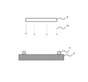
[単官能モノマーの加熱残分]
各単官能モノマーの加熱残分(%)は、熱量計測定装置(装置名:Q50、TA Instruments社製)を用いて求めた。具体的には、図8に示すように、容器12に、10mgの単官能モノマー13を入れ、単官能モノマー13を60℃で30分間加熱する前後の質量を測定することにより求めた。
[Heating residue of monofunctional monomer]
The heating residue (%) of each monofunctional monomer was determined using a calorimeter measuring device (device name: Q50, manufactured by TA Instruments). Specifically, as shown in FIG. 8, 10 mg of the
[光硬化性樹脂組成物の調製]
表1に示す配合量(質量部)で各成分を均一に混合して光硬化性樹脂組成物を調製した。
[Preparation of photocurable resin composition]
Each component was uniformly mixed in the blending amount (part by mass) shown in Table 1 to prepare a photocurable resin composition.
[光硬化性樹脂組成物の粘度]
光硬化性樹脂組成物の25℃、又は80℃における粘度を、レオメータ(RS600、HAAKE社製、コーン角度C35/2°)で測定した。
[Viscosity of photocurable resin composition]
The viscosity of the photocurable resin composition at 25 ° C. or 80 ° C. was measured with a rheometer (RS600, manufactured by HAAKE, cone angle C35 / 2 °).
[光硬化性樹脂組成物の屈折率]
各光硬化性樹脂組成物を80℃で3時間加熱した後の屈折率と、加熱する前の屈折率をアッベ屈折率計(ナトリウムD線(585nm)、25℃)を用いて測定した。
[Refractive index of photocurable resin composition]
The refractive index after heating each photocurable resin composition at 80 ° C. for 3 hours and the refractive index before heating were measured using an Abbe refractive index meter (sodium D line (585 nm), 25 ° C.).
[光硬化性樹脂組成物の加熱残分]
各光硬化性樹脂組成物の加熱残分(%)は、熱量計測定装置(装置名:Q50、TA Instruments社製)を用いて求めた。具体的には、図9に示すように、容器14に、10mgの光硬化性樹脂組成物15を入れ、光硬化性樹脂組成物15を80℃で3時間加熱する前後の質量を測定することにより求めた。
[The heating residue of the photocurable resin composition]
The heating residue (%) of each photocurable resin composition was determined using a calorimeter measuring device (device name: Q50, manufactured by TA Instruments). Specifically, as shown in FIG. 9, 10 mg of the
[光硬化性樹脂組成物を加熱しない場合の接着強度]
図10、図11に示すように、厚さ1.1mmのガラス板16の中央部に光硬化性樹脂組成物を滴下し、0.15mmのスペーサ19を介して、厚さ1.1mmのガラス板17を直交するように載置した。これにより、ガラス板16、17の間に、直径6mm、厚さ0.15mmの樹脂組成物層18が形成されたガラス接合体20を得た。
[Adhesive strength when the photocurable resin composition is not heated]
As shown in FIGS. 10 and 11, a photocurable resin composition was dropped onto the central portion of a
図12、図13に示すように、紫外線照射器9を用いて、積算光量が5000mJ/cm2となるように、ガラス板17側から紫外線10を照射して樹脂組成物層18を硬化させ、硬化樹脂層21を形成した。
As shown in FIGS. 12 and 13, the
図14に示すように、ガラス接合体20のガラス板16、17を治具22A、22Bで固定するとともに、治具22B側から垂直方向に5mm/分の速度で押し込み、以下の基準で接着状態を評価した。接着強度の測定には、荷重試験機(JSV−1000、日本計測システム社製)を用いた。接着強度は、25℃においてガラス板16とガラス板17とが分離するまでに要した応力を測定し、その応力を硬化樹脂層21の単位面積で除することにより算出した。
As shown in FIG. 14, the
[光硬化性樹脂組成物を加熱する場合の接着強度]
ガラス板16に滴下する光硬化性樹脂組成物として、80℃で3時間加熱したものを用いたこと以外は、上述した光硬化性樹脂組成物を加熱しない場合の接着強度の測定と同様に行った。
[Adhesive strength when heating a photocurable resin composition]
As the photocurable resin composition dropped onto the
[透過率]
紫外可視分光光度計(島津製作所製、UV−2450)を用いて、ガラス接合体20における硬化樹脂層21の可視光領域の透過率を測定した。実用上、硬化樹脂層21の透過率が90%以上であることが好ましい。
[Transmittance]
The transmittance of the cured
実施例の光硬化性樹脂組成物は、加熱することにより粘度が低くなる。そのため、ダムフィルプロセスにおいて、ダム材(第1の樹脂組成物)とフィル材(第2の樹脂組成物)として同一成分の樹脂組成物を用いた場合でも、ダム材の高粘度性と、フィル材の低粘度性とを両立できる。 The photocurable resin composition of Examples has a low viscosity when heated. Therefore, even when a resin composition having the same composition as the dam material (first resin composition) and the fill material (second resin composition) is used in the dam fill process, the high viscosity of the dam material and the fill It is possible to achieve both low viscosity of the material.
また、実施例の光硬化性樹脂組成物は、60℃で30分間加熱後の加熱残分が95.0%以上である単官能モノマーを含有し、かつ80℃で3時間加熱後の加熱残分が95.0%以上である。そのため、予め硬化性樹脂組成物を加熱した場合でも、接着強度が良好であることが分かった。これにより、例えばダムフィルプロセスにおいて、フィル材を加熱する際に、フィル材中の成分の揮発を抑制でき、部材同士の密着性を良好にできる。 Further, the photocurable resin composition of the example contains a monofunctional monomer having a heating residue of 95.0% or more after heating at 60 ° C. for 30 minutes, and a heating residue after heating at 80 ° C. for 3 hours. The minute is 95.0% or more. Therefore, it was found that the adhesive strength was good even when the curable resin composition was heated in advance. Thereby, for example, in the dam fill process, when the fill material is heated, the volatilization of the components in the fill material can be suppressed, and the adhesion between the members can be improved.
一方、80℃で3時間加熱後の加熱残分が95.0%未満の樹脂組成物を用いた比較例1、2では、予め樹脂組成物を加熱した場合、接着強度が良好ではないことが分かった。そのため、例えばダムフィルプロセスにおいて、フィル材を加熱する際に、フィル材中の成分の揮発を抑制できず、部材同士の密着性を良好にすることが困難である。また、比較例3、4では、樹脂組成物として、60℃で30分間加熱後の加熱残分が95.0%以上である単官能モノマーを含有しない樹脂組成物を用いたため、接着強度が良好ではないことが分かった。 On the other hand, in Comparative Examples 1 and 2 in which the resin composition having a residual heating residue of less than 95.0% after heating at 80 ° C. for 3 hours was used, the adhesive strength was not good when the resin composition was heated in advance. Do you get it. Therefore, for example, in the dam fill process, when the fill material is heated, the volatilization of the components in the fill material cannot be suppressed, and it is difficult to improve the adhesion between the members. Further, in Comparative Examples 3 and 4, as the resin composition, a resin composition containing no monofunctional monomer having a heating residue of 95.0% or more after heating at 60 ° C. for 30 minutes was used, so that the adhesive strength was good. It turned out not.
1 硬化樹脂層、2 画像表示部材、3 光透過性部材、4 遮光層、5 画像表示装置、6 第1の樹脂組成物、7 第2の樹脂組成物の塗布領域、8 第2の樹脂組成物、9 紫外線照射器、10 紫外線、11 液止め部(ダム)、12 容器、13 単官能モノマー、14 容器、15 光硬化性樹脂組成物、16 ガラス板、17 ガラス板、18 樹脂組成物層、19 スペーサ、20 ガラス接合体、21 硬化樹脂層、22A,22B 治具 1 Cured resin layer, 2 Image display member, 3 Light transmissive member, 4 Light-shielding layer, 5 Image display device, 6 First resin composition, 7 Second resin composition coating area, 8 Second resin composition Object, 9 UV irradiator, 10 UV, 11 Liquid stop (dam), 12 container, 13 monofunctional monomer, 14 container, 15 photocurable resin composition, 16 glass plate, 17 glass plate, 18 resin composition layer , 19 spacers, 20 glass joints, 21 hardened resin layer, 22A, 22B jigs
Claims (13)
上記塗布領域に上記第2の樹脂組成物を塗布する工程(B)と、
上記第1の部材と、第2の部材とを、上記第2の樹脂組成物を介して貼合せ、上記第2の樹脂組成物を上記塗布領域に充填させる工程(C)と、
上記第2の樹脂組成物に光を照射して硬化樹脂層を形成する工程(D)とを有し、
上記工程(C)は、上記第2の樹脂組成物を加熱することを含み、
上記第2の樹脂組成物は、60℃で30分間加熱後の加熱残分が95.0%以上である単官能モノマーを含有し、
上記第2の樹脂組成物は、80℃で3時間加熱後の加熱残分が95.0%以上であり、
上記単官能モノマーは、式(A)で表される化合物、及び式(B)で表される化合物の少なくとも1種である、積層体の製造方法。
The step (B) of applying the second resin composition to the coating region, and
A step (C) of laminating the first member and the second member via the second resin composition and filling the coating region with the second resin composition.
It has a step (D) of irradiating the second resin composition with light to form a cured resin layer.
The step (C) includes heating the second resin composition.
The second resin composition contains a monofunctional monomer having a heating residue of 95.0% or more after heating at 60 ° C. for 30 minutes.
The second resin composition has a heating residue of 95.0% or more after heating at 80 ° C. for 3 hours.
The method for producing a laminate, wherein the monofunctional monomer is at least one of a compound represented by the formula (A) and a compound represented by the formula (B).
上記塗布領域に上記第2の樹脂組成物を塗布する工程(B)と、
上記第1の部材と、第2の部材とを、上記第2の樹脂組成物を介して貼合せ、上記第2の樹脂組成物を上記塗布領域に充填させる工程(C)と、
上記第2の樹脂組成物に光を照射して硬化樹脂層を形成する工程(D)とを有し、
上記工程(C)は、上記第2の樹脂組成物を加熱することを含み、
上記第2の樹脂組成物は、60℃で30分間加熱後の加熱残分が95.0%以上である単官能モノマーを含有し、
上記第2の樹脂組成物は、80℃で3時間加熱後の加熱残分が95.0%以上であり、
上記単官能モノマーは、イソステアリル(メタ)アクリレート、ノニルフェノールEO変性(メタ)アクリレート、ノニルフェノールPO変性(メタ)アクリレート、2−エチルヘキシルEO変性(メタ)アクリレート、フェノールEO変性(メタ)アクリレート、о−フェニルフェノールEO変性アクリレート、パラクミルフェノールEO変性アクリレート、N−アクリロイルオキシエチルヘキサヒドロフタルイミド、及び2−ヒドロキシ−3−フェノキシプロピルアクリレートの少なくとも1種である、積層体の製造方法。 A step (A) of forming a coating region of the photocurable second resin composition on the surface of the first member by using the first resin composition.
The step (B) of applying the second resin composition to the coating region, and
A step (C) of laminating the first member and the second member via the second resin composition and filling the coating region with the second resin composition.
It has a step (D) of irradiating the second resin composition with light to form a cured resin layer.
The step (C) includes heating the second resin composition.
The second resin composition contains a monofunctional monomer having a heating residue of 95.0% or more after heating at 60 ° C. for 30 minutes.
The second resin composition has a heating residue of 95.0% or more after heating at 80 ° C. for 3 hours.
The monofunctional monomer includes isostearyl (meth) acrylate, nonylphenol EO modified (meth) acrylate, nonylphenol PO modified (meth) acrylate, 2-ethylhexyl EO modified (meth) acrylate, phenol EO modified (meth) acrylate, and о-phenyl. A method for producing a laminate, which is at least one of a phenol EO modified acrylate, a paracumylphenol EO modified acrylate, an N-acryloyloxyethyl hexahydrophthalimide, and a 2-hydroxy-3-phenoxypropyl acrylate.
上記(メタ)アクリレート樹脂の含有量は10〜60質量%であり、
上記可塑剤の含有量は10〜70質量%である、請求項5に記載の積層体の製造方法。 In the second resin composition,
The content of the above SL (meth) acrylate resin is 10 to 60 wt%,
The method for producing a laminate according to claim 5 , wherein the content of the plasticizer is 10 to 70% by mass.
上記工程(C)では、上記加熱により上記第2の樹脂組成物の粘度を3000mPa・s以下にした状態で上記塗布領域に充填させる、請求項1〜8のいずれか1項に記載の積層体の製造方法。 In the step (B), the second resin composition having a viscosity at 25 ° C. of 1000 to 50000 mPa · s is applied.
The laminate according to any one of claims 1 to 8, wherein in the step (C), the coating region is filled with the viscosity of the second resin composition set to 3000 mPa · s or less by the heating. Manufacturing method.
上記積層体は、画像表示装置である、請求項1〜12のいずれか1項に記載の積層体の製造方法。 The first member or the second member is an image display member.
The method for manufacturing a laminate according to any one of claims 1 to 12, wherein the laminate is an image display device.
Priority Applications (11)
| Application Number | Priority Date | Filing Date | Title |
|---|---|---|---|
| JP2017037614A JP6938168B2 (en) | 2017-02-28 | 2017-02-28 | Method for producing a laminate and a photocurable resin composition |
| KR1020197014614A KR102318425B1 (en) | 2017-02-28 | 2018-01-12 | Method for producing a laminate, and a photocurable resin composition |
| CN202110418562.8A CN113372823B (en) | 2017-02-28 | 2018-01-12 | Method for producing laminate and photocurable resin composition |
| CN201880010675.0A CN110234506B (en) | 2017-02-28 | 2018-01-12 | Method for producing laminate and photocurable resin composition |
| KR1020217034227A KR20210130272A (en) | 2017-02-28 | 2018-01-12 | Manufacturing method for laminated body, and photocurable resin composition |
| DE112018001039.2T DE112018001039T5 (en) | 2017-02-28 | 2018-01-12 | A process for producing a laminated body and photocurable resin composition |
| PCT/JP2018/000578 WO2018159110A1 (en) | 2017-02-28 | 2018-01-12 | Manufacturing method for laminated body, and photocurable resin composition |
| KR1020247007186A KR20240034266A (en) | 2017-02-28 | 2018-01-12 | Manufacturing method for laminated body, and photocurable resin composition |
| TW107105499A TW201834848A (en) | 2017-02-28 | 2018-02-14 | Method for producing laminate, and photocurable resin composition |
| JP2021142177A JP2022000508A (en) | 2017-02-28 | 2021-09-01 | Photocurable resin composition |
| JP2023075432A JP2023086991A (en) | 2017-02-28 | 2023-05-01 | Curable resin layer |
Applications Claiming Priority (1)
| Application Number | Priority Date | Filing Date | Title |
|---|---|---|---|
| JP2017037614A JP6938168B2 (en) | 2017-02-28 | 2017-02-28 | Method for producing a laminate and a photocurable resin composition |
Related Child Applications (1)
| Application Number | Title | Priority Date | Filing Date |
|---|---|---|---|
| JP2021142177A Division JP2022000508A (en) | 2017-02-28 | 2021-09-01 | Photocurable resin composition |
Publications (3)
| Publication Number | Publication Date |
|---|---|
| JP2018140601A JP2018140601A (en) | 2018-09-13 |
| JP2018140601A5 JP2018140601A5 (en) | 2020-03-05 |
| JP6938168B2 true JP6938168B2 (en) | 2021-09-22 |
Family
ID=63371163
Family Applications (3)
| Application Number | Title | Priority Date | Filing Date |
|---|---|---|---|
| JP2017037614A Active JP6938168B2 (en) | 2017-02-28 | 2017-02-28 | Method for producing a laminate and a photocurable resin composition |
| JP2021142177A Pending JP2022000508A (en) | 2017-02-28 | 2021-09-01 | Photocurable resin composition |
| JP2023075432A Pending JP2023086991A (en) | 2017-02-28 | 2023-05-01 | Curable resin layer |
Family Applications After (2)
| Application Number | Title | Priority Date | Filing Date |
|---|---|---|---|
| JP2021142177A Pending JP2022000508A (en) | 2017-02-28 | 2021-09-01 | Photocurable resin composition |
| JP2023075432A Pending JP2023086991A (en) | 2017-02-28 | 2023-05-01 | Curable resin layer |
Country Status (6)
| Country | Link |
|---|---|
| JP (3) | JP6938168B2 (en) |
| KR (3) | KR20240034266A (en) |
| CN (2) | CN110234506B (en) |
| DE (1) | DE112018001039T5 (en) |
| TW (1) | TW201834848A (en) |
| WO (1) | WO2018159110A1 (en) |
Families Citing this family (2)
| Publication number | Priority date | Publication date | Assignee | Title |
|---|---|---|---|---|
| JP2023031994A (en) * | 2021-08-26 | 2023-03-09 | デクセリアルズ株式会社 | Photocurable material and image display device |
| KR20230093749A (en) * | 2021-12-20 | 2023-06-27 | 주식회사 동진쎄미켐 | Adhesive composition with excellent adhesion and reliability |
Family Cites Families (25)
| Publication number | Priority date | Publication date | Assignee | Title |
|---|---|---|---|---|
| DE19836694A1 (en) * | 1998-08-13 | 2000-02-17 | Metallgesellschaft Ag | Laminated glass consisting of a sandwich of two or more glass panels with adhesive between the panels, useful as safety glass, noise attenuation, and for solar modules are obtained without de-aeration and edge sealing |
| DE19836695A1 (en) * | 1998-08-13 | 2000-02-24 | Metallgesellschaft Ag | Adhesive for production of laminated glass, e.g. safety glass, contains acrylic monomers, acrylate-functional oligomers, coupling agent and photoinitiator, optionally with inert polymer and other additives |
| JP3484985B2 (en) * | 1998-08-17 | 2004-01-06 | 東亞合成株式会社 | Photocurable adhesive composition |
| CN1944548B (en) * | 2006-06-09 | 2010-04-07 | 日本精工油墨股份有限公司 | Printing ink using ultraviolet cured resin composition as active ingradient |
| US20100033661A1 (en) | 2007-04-09 | 2010-02-11 | Sony Chemical & Information Device Corporation | Image display device |
| WO2009139357A1 (en) * | 2008-05-12 | 2009-11-19 | 電気化学工業株式会社 | Method for protection of surface of material to be processed, and temporary fixing method |
| TWI485214B (en) * | 2008-09-05 | 2015-05-21 | Kyoritsu Chemical Co Ltd | And a photohardenable resin composition for bonding an optical functional material |
| WO2011083652A1 (en) * | 2010-01-07 | 2011-07-14 | 日本合成化学工業株式会社 | Actinic-radiation curable composition and uses thereof |
| TWI465534B (en) * | 2010-12-31 | 2014-12-21 | Eternal Materials Co Ltd | Photocurable adhesive composition |
| JP2012144634A (en) * | 2011-01-12 | 2012-08-02 | Jsr Corp | Optical resin and method for producing optical resin layer, composition for optical resin, and image display device |
| TW201317315A (en) * | 2011-08-26 | 2013-05-01 | Denki Kagaku Kogyo Kk | Curable resin composition |
| JP5880830B2 (en) * | 2011-12-20 | 2016-03-09 | Jsr株式会社 | Image display device |
| JP2013203843A (en) * | 2012-03-28 | 2013-10-07 | Kyoritsu Kagaku Sangyo Kk | Photocurable resin composition for laminating decoratively printed front plate and optical display panel or touch panel, and optical display or touch sensor made by laminating using the resin composition |
| WO2013187508A1 (en) * | 2012-06-15 | 2013-12-19 | 昭和電工株式会社 | Polymerizable composition, polymer, optical adhesive sheet, image display device, and method for manufacturing image display device |
| TW201420718A (en) * | 2012-09-20 | 2014-06-01 | Mitsubishi Rayon Co | Photocuring adhesive agent composition, cured object, adhesive sheet and display panel and producing method thereof |
| JP5935668B2 (en) * | 2012-11-27 | 2016-06-15 | 東亞合成株式会社 | Active energy ray-curable coating agent composition |
| JP6130154B2 (en) * | 2013-01-31 | 2017-05-17 | デンカ株式会社 | Curable resin composition |
| JP6335881B2 (en) * | 2013-03-28 | 2018-05-30 | セーレン株式会社 | Decorative film for insert molding and decorative insert molded product |
| CN105518764B (en) * | 2013-09-09 | 2019-11-08 | 日本化药株式会社 | The manufacturing method of optical component and ultraviolet-curing resin composition for the manufacturing method |
| JP6404552B2 (en) * | 2013-09-13 | 2018-10-10 | デンカ株式会社 | Curable resin composition |
| JP2015067677A (en) * | 2013-09-27 | 2015-04-13 | 三洋化成工業株式会社 | Photocurable composition for adhesion |
| TW201522081A (en) * | 2013-09-27 | 2015-06-16 | Denki Kagaku Kogyo Kk | Laminate, manufacturing method thereof, and separation method thereof |
| JP2015147916A (en) * | 2014-02-10 | 2015-08-20 | 日本化薬株式会社 | Uv-curable adhesive composition for touch panel, and bonding method and article using the same |
| TWI685531B (en) * | 2014-05-22 | 2020-02-21 | 日商迪睿合股份有限公司 | Acrylic thermal conductive composition and thermal conductive sheet |
| KR20190092486A (en) * | 2016-12-14 | 2019-08-07 | 덴카 주식회사 | Composition |
-
2017
- 2017-02-28 JP JP2017037614A patent/JP6938168B2/en active Active
-
2018
- 2018-01-12 KR KR1020247007186A patent/KR20240034266A/en unknown
- 2018-01-12 CN CN201880010675.0A patent/CN110234506B/en active Active
- 2018-01-12 DE DE112018001039.2T patent/DE112018001039T5/en active Pending
- 2018-01-12 WO PCT/JP2018/000578 patent/WO2018159110A1/en active Application Filing
- 2018-01-12 KR KR1020217034227A patent/KR20210130272A/en not_active Application Discontinuation
- 2018-01-12 CN CN202110418562.8A patent/CN113372823B/en active Active
- 2018-01-12 KR KR1020197014614A patent/KR102318425B1/en active IP Right Grant
- 2018-02-14 TW TW107105499A patent/TW201834848A/en unknown
-
2021
- 2021-09-01 JP JP2021142177A patent/JP2022000508A/en active Pending
-
2023
- 2023-05-01 JP JP2023075432A patent/JP2023086991A/en active Pending
Also Published As
| Publication number | Publication date |
|---|---|
| CN110234506B (en) | 2021-05-11 |
| JP2022000508A (en) | 2022-01-04 |
| CN110234506A (en) | 2019-09-13 |
| KR20240034266A (en) | 2024-03-13 |
| DE112018001039T5 (en) | 2019-11-28 |
| KR102318425B1 (en) | 2021-10-28 |
| KR20210130272A (en) | 2021-10-29 |
| CN113372823A (en) | 2021-09-10 |
| WO2018159110A1 (en) | 2018-09-07 |
| TW201834848A (en) | 2018-10-01 |
| KR20190072606A (en) | 2019-06-25 |
| JP2023086991A (en) | 2023-06-22 |
| JP2018140601A (en) | 2018-09-13 |
| CN113372823B (en) | 2023-05-26 |
Similar Documents
| Publication | Publication Date | Title |
|---|---|---|
| JP5811143B2 (en) | Display device | |
| KR102277736B1 (en) | Method of manufacturing image display device | |
| JP5757291B2 (en) | Method for producing transparent face material with adhesive layer | |
| JP5401824B2 (en) | Image display device | |
| JP6127745B2 (en) | Photocurable resin composition and method for manufacturing image display device | |
| JP2023086991A (en) | Curable resin layer | |
| TWI433822B (en) | A method of manufacturing a display device | |
| JP5706912B2 (en) | Display panel assembly and manufacturing method thereof | |
| TWI738661B (en) | Photocurable resin composition and manufacturing method of image display device | |
| US10689546B2 (en) | Method for manufacturing optical member | |
| JP2019094485A (en) | Photocurable resin composition, and method for manufacturing image display device | |
| JP5742840B2 (en) | Manufacturing method of laminate | |
| JP6538252B1 (en) | Method of manufacturing image display device | |
| TW201821448A (en) | Method for producing laminate and photocurable resin composition | |
| JP7160745B2 (en) | Method for manufacturing image display device | |
| JP2015060000A (en) | Display device manufacturing method | |
| WO2017038845A1 (en) | Photocurable resin composition and method for manufacturing image display device | |
| JP2015087469A (en) | Display device and method for manufacturing the same | |
| CN111448222A (en) | Photocurable resin composition | |
| WO2019102928A1 (en) | Photocurable resin composition and method for manufacturing image display device | |
| KR20160069908A (en) | Optical clear resin having a superior thixotropy |
Legal Events
| Date | Code | Title | Description |
|---|---|---|---|
| A521 | Request for written amendment filed |
Free format text: JAPANESE INTERMEDIATE CODE: A523 Effective date: 20200122 |
|
| A621 | Written request for application examination |
Free format text: JAPANESE INTERMEDIATE CODE: A621 Effective date: 20200122 |
|
| A131 | Notification of reasons for refusal |
Free format text: JAPANESE INTERMEDIATE CODE: A131 Effective date: 20201215 |
|
| A521 | Request for written amendment filed |
Free format text: JAPANESE INTERMEDIATE CODE: A523 Effective date: 20210212 |
|
| A131 | Notification of reasons for refusal |
Free format text: JAPANESE INTERMEDIATE CODE: A131 Effective date: 20210427 |
|
| A521 | Request for written amendment filed |
Free format text: JAPANESE INTERMEDIATE CODE: A523 Effective date: 20210525 |
|
| TRDD | Decision of grant or rejection written | ||
| A01 | Written decision to grant a patent or to grant a registration (utility model) |
Free format text: JAPANESE INTERMEDIATE CODE: A01 Effective date: 20210803 |
|
| A61 | First payment of annual fees (during grant procedure) |
Free format text: JAPANESE INTERMEDIATE CODE: A61 Effective date: 20210901 |
|
| R150 | Certificate of patent or registration of utility model |
Ref document number: 6938168 Country of ref document: JP Free format text: JAPANESE INTERMEDIATE CODE: R150 |