JP6935812B2 - Tire wear detector - Google Patents

Tire wear detector Download PDF

Info

Publication number
JP6935812B2
JP6935812B2 JP2019224168A JP2019224168A JP6935812B2 JP 6935812 B2 JP6935812 B2 JP 6935812B2 JP 2019224168 A JP2019224168 A JP 2019224168A JP 2019224168 A JP2019224168 A JP 2019224168A JP 6935812 B2 JP6935812 B2 JP 6935812B2
Authority
JP
Japan
Prior art keywords
tire
unit
wear
information
vibration
Prior art date
Legal status (The legal status is an assumption and is not a legal conclusion. Google has not performed a legal analysis and makes no representation as to the accuracy of the status listed.)
Active
Application number
JP2019224168A
Other languages
Japanese (ja)
Other versions
JP2020164147A5 (en
JP2020164147A (en
Inventor
洋一朗 鈴木
洋一朗 鈴木
高俊 関澤
高俊 関澤
Current Assignee (The listed assignees may be inaccurate. Google has not performed a legal analysis and makes no representation or warranty as to the accuracy of the list.)
Denso Corp
Original Assignee
Denso Corp
Priority date (The priority date is an assumption and is not a legal conclusion. Google has not performed a legal analysis and makes no representation as to the accuracy of the date listed.)
Filing date
Publication date
Application filed by Denso Corp filed Critical Denso Corp
Priority to PCT/JP2019/048739 priority Critical patent/WO2020122189A1/en
Publication of JP2020164147A publication Critical patent/JP2020164147A/en
Publication of JP2020164147A5 publication Critical patent/JP2020164147A5/ja
Priority to US17/343,018 priority patent/US20210291597A1/en
Application granted granted Critical
Publication of JP6935812B2 publication Critical patent/JP6935812B2/en
Active legal-status Critical Current
Anticipated expiration legal-status Critical

Links

Images

Classifications

    • BPERFORMING OPERATIONS; TRANSPORTING
    • B60VEHICLES IN GENERAL
    • B60CVEHICLE TYRES; TYRE INFLATION; TYRE CHANGING; CONNECTING VALVES TO INFLATABLE ELASTIC BODIES IN GENERAL; DEVICES OR ARRANGEMENTS RELATED TO TYRES
    • B60C11/00Tyre tread bands; Tread patterns; Anti-skid inserts
    • B60C11/24Wear-indicating arrangements
    • B60C11/246Tread wear monitoring systems
    • GPHYSICS
    • G07CHECKING-DEVICES
    • G07CTIME OR ATTENDANCE REGISTERS; REGISTERING OR INDICATING THE WORKING OF MACHINES; GENERATING RANDOM NUMBERS; VOTING OR LOTTERY APPARATUS; ARRANGEMENTS, SYSTEMS OR APPARATUS FOR CHECKING NOT PROVIDED FOR ELSEWHERE
    • G07C5/00Registering or indicating the working of vehicles
    • G07C5/08Registering or indicating performance data other than driving, working, idle, or waiting time, with or without registering driving, working, idle or waiting time
    • G07C5/0816Indicating performance data, e.g. occurrence of a malfunction
    • BPERFORMING OPERATIONS; TRANSPORTING
    • B60VEHICLES IN GENERAL
    • B60CVEHICLE TYRES; TYRE INFLATION; TYRE CHANGING; CONNECTING VALVES TO INFLATABLE ELASTIC BODIES IN GENERAL; DEVICES OR ARRANGEMENTS RELATED TO TYRES
    • B60C11/00Tyre tread bands; Tread patterns; Anti-skid inserts
    • B60C11/24Wear-indicating arrangements
    • B60C11/243Tread wear sensors, e.g. electronic sensors
    • GPHYSICS
    • G01MEASURING; TESTING
    • G01MTESTING STATIC OR DYNAMIC BALANCE OF MACHINES OR STRUCTURES; TESTING OF STRUCTURES OR APPARATUS, NOT OTHERWISE PROVIDED FOR
    • G01M17/00Testing of vehicles
    • G01M17/007Wheeled or endless-tracked vehicles
    • G01M17/02Tyres
    • G01M17/025Tyres using infrasonic, sonic or ultrasonic vibrations
    • GPHYSICS
    • G06COMPUTING; CALCULATING OR COUNTING
    • G06VIMAGE OR VIDEO RECOGNITION OR UNDERSTANDING
    • G06V20/00Scenes; Scene-specific elements
    • G06V20/50Context or environment of the image
    • G06V20/56Context or environment of the image exterior to a vehicle by using sensors mounted on the vehicle
    • GPHYSICS
    • G07CHECKING-DEVICES
    • G07CTIME OR ATTENDANCE REGISTERS; REGISTERING OR INDICATING THE WORKING OF MACHINES; GENERATING RANDOM NUMBERS; VOTING OR LOTTERY APPARATUS; ARRANGEMENTS, SYSTEMS OR APPARATUS FOR CHECKING NOT PROVIDED FOR ELSEWHERE
    • G07C5/00Registering or indicating the working of vehicles
    • G07C5/02Registering or indicating driving, working, idle, or waiting time only
    • HELECTRICITY
    • H04ELECTRIC COMMUNICATION TECHNIQUE
    • H04QSELECTING
    • H04Q9/00Arrangements in telecontrol or telemetry systems for selectively calling a substation from a main station, in which substation desired apparatus is selected for applying a control signal thereto or for obtaining measured values therefrom

Description

本発明は、タイヤ側装置からのタイヤの摩耗状態を示す摩耗データに基づきタイヤ摩耗状態を報知するタイヤ摩耗検知装置に関する。 The present invention relates to a tire wear detection device that notifies a tire wear state based on wear data indicating a tire wear state from a tire side device.

従来、タイヤ摩耗状態を検知するものとして、特許文献1に示すタイヤ摩耗検知装置がある。このタイヤ摩耗検知装置では、加速度の時系列波形から、タイヤのゴムブロックが路面に踏み込んだときに発生する踏み込み時のピークを含む踏み込み領域の加速度波形と、路面から離れるときに発生する蹴り出し時のピークを含む蹴り出し領域の加速度波形を抽出している。そして、抽出されたそれぞれの加速度波形を周波数分解して得られた周波数特性の違いから、タイヤ摩耗状態を検出している。 Conventionally, there is a tire wear detection device shown in Patent Document 1 as a device for detecting a tire wear state. In this tire wear detection device, from the time-series waveform of acceleration, the acceleration waveform of the stepping area including the peak at the time of stepping on the rubber block of the tire when stepping on the road surface and the time of kicking out when leaving the road surface The acceleration waveform of the kick-out region including the peak of is extracted. Then, the tire wear state is detected from the difference in frequency characteristics obtained by frequency-resolving each of the extracted acceleration waveforms.

特開2009−18667号公報Japanese Unexamined Patent Publication No. 2009-18667

しかしながら、特許文献1のようなタイヤ摩耗状態の検知手法では、タイヤのブロックが路面に接地したときに発生する加速度波形のパルスを正確に検出する必要がある。このため、荒れ路面のように、実際の走行路面の状態に起因した外乱が入力されると、踏み込み領域や蹴り出し領域の加速度波形の抽出を的確に行えなくなる可能性がある。このような場合、タイヤ摩耗検知装置によるタイヤ摩耗の検知精度が低下する。 However, in the tire wear state detection method as in Patent Document 1, it is necessary to accurately detect the pulse of the acceleration waveform generated when the tire block touches the road surface. Therefore, if a disturbance caused by an actual running road surface condition such as a rough road surface is input, it may not be possible to accurately extract the acceleration waveform in the stepping region or the kicking region. In such a case, the accuracy of detecting tire wear by the tire wear detecting device is lowered.

本発明は上記点に鑑みて、より精度良くタイヤ摩耗状態を検知することができるタイヤ摩耗検知装置を提供することを目的とする。 In view of the above points, an object of the present invention is to provide a tire wear detection device capable of detecting a tire wear state with higher accuracy.

上記目的を達成するため、請求項1に記載のタイヤ摩耗検知装置は、車両に備えられる複数のタイヤ(3)にそれぞれ配置され、タイヤの振動の大きさに応じた検出信号を出力する振動検出部(11)と、車両の速度である車速を推定する車速推定部(12)と、検出信号の波形に現れるタイヤの摩耗状態を示す摩耗データを生成する信号処理部(13)と、摩耗データを送信する第1データ通信部(14)と、を備えるタイヤ側装置(1)と、車体側に備えられ、摩耗データを受信する第2データ通信部(21a)と、摩耗データに基づいてタイヤ摩耗状態を判定する摩耗判定部(21ba)を含む制御部(21b)と、を備える車体側システム(2)と、を有し、信号処理部は、車速推定部で推定された車速に基づいて、検出信号の取込み範囲を決めて取込み、取り込んだ検出信号からタイヤのゴムブロックを含むタイヤの固有振動周波数に基づく所定周波数帯の振動レベルのレベル値を求めて摩耗データとする。 In order to achieve the above object, the tire wear detection device according to claim 1 is arranged on each of a plurality of tires (3) provided in the vehicle, and vibration detection that outputs a detection signal according to the magnitude of tire vibration. A unit (11), a vehicle speed estimation unit (12) that estimates the vehicle speed, which is the speed of the vehicle, a signal processing unit (13) that generates wear data indicating a tire wear state that appears in the waveform of the detection signal, and wear data. A tire-side device (1) including a first data communication unit (14) for transmitting the data, a second data communication unit (21a) provided on the vehicle body side for receiving wear data, and a tire based on the wear data. It has a control unit (21b) including a wear determination unit (21ba) for determining a wear state, and a vehicle body side system (2) including the wear determination unit (21ba), and the signal processing unit is based on the vehicle speed estimated by the vehicle speed estimation unit. , The capture range of the detection signal is determined and captured, and the level value of the vibration level in the predetermined frequency band based on the natural vibration frequency of the tire including the rubber block of the tire is obtained from the captured detection signal and used as wear data.

このように、振動検出部の検出信号の振動レベルのレベル値に基づいてタイヤの摩耗状態を検知している。タイヤの摩耗により、ゴムブロックが薄くなり、バネ定数が大きくなることから、振動検出部の検出信号の高周波成分の振動レベルのレベル値が大きくなる。そして、振動検出部の検出信号の高周波成分の振動レベルについては、タイヤの1回転のどの部分においても、摩耗が進んだ後の方が摩耗前の新品の時よりも大きくなる。 In this way, the tire wear state is detected based on the level value of the vibration level of the detection signal of the vibration detection unit. As the tire wears, the rubber block becomes thinner and the spring constant increases, so that the level value of the vibration level of the high-frequency component of the detection signal of the vibration detection unit increases. The vibration level of the high-frequency component of the detection signal of the vibration detection unit is higher after the tire has been worn than when it is new before the wear, in any part of one rotation of the tire.

したがって、踏み込み領域や蹴り出し領域の加速度波形を的確に抽出する必要はなく、タイヤの1回転中の振動波形を取り込めば良い。そして、タイヤの1回転中の振動波形における特定周波数帯の振動レベルのレベル値に基づいて、的確にタイヤ摩耗状態を検知できる。これにより、より精度良くタイヤ摩耗状態を検知することが可能となる。 Therefore, it is not necessary to accurately extract the acceleration waveform in the stepping region and the kicking region, and it is sufficient to capture the vibration waveform during one rotation of the tire. Then, the tire wear state can be accurately detected based on the level value of the vibration level in the specific frequency band in the vibration waveform during one rotation of the tire. This makes it possible to detect the tire wear state with higher accuracy.

なお、各構成要素等に付された括弧付きの参照符号は、その構成要素等と後述する実施形態に記載の具体的な構成要素等との対応関係の一例を示すものである。 The reference reference numerals in parentheses attached to each component or the like indicate an example of the correspondence between the component or the like and the specific component or the like described in the embodiment described later.

第1実施形態にかかるタイヤ摩耗検知装置のブロック構成を示した図である。It is a figure which showed the block structure of the tire wear detection device which concerns on 1st Embodiment. タイヤ側装置および受信機の詳細構成を示したブロック図である。It is a block diagram which showed the detailed structure of a tire side device and a receiver. タイヤ側装置が取り付けられたタイヤの断面模式図である。It is sectional drawing of the tire which attached the tire side device. タイヤ回転時における振動センサ部の出力電圧波形図である。It is the output voltage waveform figure of the vibration sensor part at the time of tire rotation. タイヤの振動モデルを示した図である。It is a figure which showed the vibration model of a tire. 一般的な振動モデルの図である。It is a figure of a general vibration model. 新品のタイヤと摩耗後のタイヤそれぞれについてタイヤの振動レベルの周波数特性を調べたときの結果を示す図である。It is a figure which shows the result when the frequency characteristic of the vibration level of a tire was investigated for each of a new tire and a worn tire. 新品のタイヤと摩耗後のタイヤそれぞれについてタイヤ回転時における振動センサ部の出力電圧波形を示した比較図である。It is a comparative figure which showed the output voltage waveform of the vibration sensor part at the time of tire rotation for each of a new tire and a worn tire. 摩耗によりタイヤの溝深さが変化したときの振動スペクトルの周波数特性を示した図である。It is a figure which showed the frequency characteristic of the vibration spectrum when the groove depth of a tire changed by wear. タイヤの種類を変えて溝深さと特定周波数帯の振動レベルの積算値との関係を調べた結果を示す図である。It is a figure which shows the result of having investigated the relationship between the groove depth and the integrated value of the vibration level of a specific frequency band by changing the type of a tire. 第2実施形態にかかるタイヤ摩耗検知装置のタイヤ側装置および受信機のブロック構成を示した図である。It is a figure which showed the block structure of the tire side apparatus and the receiver of the tire wear detection apparatus which concerns on 2nd Embodiment. 第3実施形態にかかるタイヤ摩耗検知装置のタイヤ側装置および受信機のブロック構成を示した図である。It is a figure which showed the block structure of the tire side apparatus and the receiver of the tire wear detection apparatus which concerns on 3rd Embodiment. 新品のタイヤの積算値を初期値として規格化を行った場合の溝深さと特定周波数帯の振動レベルの積算値との関係を示す図である。It is a figure which shows the relationship between the groove depth and the integrated value of the vibration level of a specific frequency band when standardization is performed with the integrated value of a new tire as an initial value. タイヤが新品のときと3年相当の紫外線照射を行った紫外線劣化品それぞれについてバネ定数Kbの変化を調べた結果を示す図である。It is a figure which shows the result of having investigated the change of the spring constant Kb for each of the time when the tire was new and the UV deteriorated product which had been irradiated with ultraviolet rays for 3 years. タイヤが新品のときと3年相当の紫外線照射を行った紫外線劣化品それぞれについて積分値の変化を調べた結果を示す図である。It is a figure which shows the result of having investigated the change of the integral value for each of the time when the tire was new and the UV deteriorated product which had been irradiated with ultraviolet rays for 3 years. 第4実施形態にかかるタイヤ摩耗検知装置のタイヤ側装置および受信機のブロック構成を示した図である。It is a figure which showed the block structure of the tire side apparatus and the receiver of the tire wear detection apparatus which concerns on 4th Embodiment. 第5実施形態にかかるタイヤ摩耗検知装置のタイヤ側装置および受信機のブロック構成を示した図である。It is a figure which showed the block structure of the tire side apparatus and the receiver of the tire wear detection apparatus which concerns on 5th Embodiment. 第6実施形態にかかるタイヤ摩耗検知装置のタイヤ側装置および受信機のブロック構成を示した図である。It is a figure which showed the block structure of the tire side apparatus and the receiver of the tire wear detection apparatus which concerns on 6th Embodiment.

以下、本発明の実施形態について図に基づいて説明する。なお、以下の各実施形態相互において、互いに同一もしくは均等である部分には、同一符号を付して説明を行う。 Hereinafter, embodiments of the present invention will be described with reference to the drawings. In each of the following embodiments, parts that are the same or equal to each other will be described with the same reference numerals.

(第1実施形態)
図1〜図10を参照して、本実施形態にかかるタイヤ摩耗状態の検知機能を有するタイヤシステム100について説明する。本実施形態にかかるタイヤシステム100は、タイヤ側装置1と車体側システム2を有して構成されている。そして、タイヤシステム100は、タイヤ側装置1からタイヤ摩耗に関する情報を車体側システム2に伝え、車体側システム2にてタイヤ摩耗状態を判定してユーザに報知するなどの処理を行うものである。
(First Embodiment)
The tire system 100 having a tire wear state detecting function according to the present embodiment will be described with reference to FIGS. 1 to 10. The tire system 100 according to the present embodiment includes a tire-side device 1 and a vehicle body-side system 2. Then, the tire system 100 transmits information on tire wear from the tire side device 1 to the vehicle body side system 2, determines the tire wear state by the vehicle body side system 2, and notifies the user.

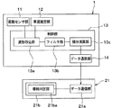
図1および図2に示すようにタイヤシステム100は、車輪側に設けられたタイヤ側装置1と、車体側に備えられた各部を含む車体側システム2とを有する構成とされている。車体側システム2には、受信機21、ブレーキ制御用の電子制御装置(以下、ブレーキECUという)22、報知装置23などが備えられている。なお、このタイヤシステム100のうちタイヤ摩耗状態の検知機能を実現する部分がタイヤ摩耗検知装置に相当する。本実施形態の場合、タイヤ側装置1と車体側システム2のうちの受信機21がタイヤ摩耗検知装置を構成している。以下、タイヤ側装置1と車体側システム2を構成する各部の詳細について説明する。 As shown in FIGS. 1 and 2, the tire system 100 has a tire-side device 1 provided on the wheel side and a vehicle body-side system 2 including various parts provided on the vehicle body side. The vehicle body side system 2 is provided with a receiver 21, an electronic control device for brake control (hereinafter referred to as a brake ECU) 22, a notification device 23, and the like. The portion of the tire system 100 that realizes the tire wear state detection function corresponds to the tire wear detection device. In the case of the present embodiment, the receiver 21 of the tire side device 1 and the vehicle body side system 2 constitutes the tire wear detection device. Hereinafter, details of each part constituting the tire side device 1 and the vehicle body side system 2 will be described.

まず、タイヤ側装置1について説明する。タイヤ側装置1は、図2に示すように、振動センサ部11、車速推定部12、制御部13およびデータ通信部14を備えた構成とされ、例えば、図3に示されるように、タイヤ3のトレッド31の裏面側に設けられる。 First, the tire side device 1 will be described. As shown in FIG. 2, the tire-side device 1 has a configuration including a vibration sensor unit 11, a vehicle speed estimation unit 12, a control unit 13, and a data communication unit 14. For example, as shown in FIG. 3, the tire 3 It is provided on the back surface side of the tread 31 of.

振動センサ部11は、タイヤ3に加わる振動を検出するための振動検出部を構成するものである。例えば、振動センサ部11は、加速度センサによって構成される。本実施形態の場合、振動センサ部11は、例えば、タイヤ3が回転する際にタイヤ側装置1が描く円軌道に対する径方向、つまり図3中の矢印Zで示すタイヤ径方向の振動の大きさに応じた検出信号として、加速度の検出信号を出力する。より詳しくは、振動センサ部11は、矢印Zで示す二方向のうちの一方向を正、反対方向を負とする出力電圧などを検出信号として発生させる。例えば、振動センサ部11は、タイヤ3が1回転するよりも短い周期に設定される所定のサンプリング周期ごとに加速度検出を行い、それを検出信号として出力している。なお、振動センサ部11の検出信号は、出力電圧もしくは出力電流として表されるが、ここでは出力電圧として表される場合を例に挙げる。 The vibration sensor unit 11 constitutes a vibration detection unit for detecting the vibration applied to the tire 3. For example, the vibration sensor unit 11 is composed of an acceleration sensor. In the case of the present embodiment, the vibration sensor unit 11 has, for example, the magnitude of vibration in the radial direction with respect to the circular orbit drawn by the tire side device 1 when the tire 3 rotates, that is, in the tire radial direction indicated by the arrow Z in FIG. The acceleration detection signal is output as the detection signal according to the above. More specifically, the vibration sensor unit 11 generates an output voltage or the like as a detection signal in which one of the two directions indicated by the arrow Z is positive and the opposite direction is negative. For example, the vibration sensor unit 11 detects acceleration at a predetermined sampling cycle set to a cycle shorter than one rotation of the tire 3, and outputs it as a detection signal. The detection signal of the vibration sensor unit 11 is represented as an output voltage or an output current, but here, a case where it is represented as an output voltage will be given as an example.

車速推定部12は、タイヤ側装置1を備えたタイヤ3が取り付けられた車両の速度(以下、単に車速という)の推定を行う。ここでは、車速推定部12は、振動センサ部11の検出信号に基づいて車速を推定している。 The vehicle speed estimation unit 12 estimates the speed (hereinafter, simply referred to as vehicle speed) of a vehicle to which the tire 3 provided with the tire side device 1 is attached. Here, the vehicle speed estimation unit 12 estimates the vehicle speed based on the detection signal of the vibration sensor unit 11.

タイヤ回転時における振動センサ部11の検出信号の出力電圧波形は、例えば図4に示す波形となる。この図に示されるように、タイヤ3の回転に伴ってトレッド31のうちタイヤ側装置1の配置箇所と対応する部分(以下、装置配置箇所という)が接地し始めた接地開始時に、振動センサ部11の出力電圧が極大値をとる。以下、この振動センサ部11の出力電圧が極大値をとる接地開始時のピーク値を第1ピーク値という。また、図4に示されるように、タイヤ3の回転に伴って装置配置箇所と対応する部分が接地していた状態から接地しなくなる接地終了時に、振動センサ部11の出力電圧がもう一度極大値をとる。以下、この振動センサ部11の出力電圧が極大値をとる接地終了時のピーク値を第2ピーク値という。さらに、図4に示されるように、装置配置箇所の接地中には、遠心加速度の影響を受けなくなるため、振動センサ部11の出力電圧が最も低い値になる。 The output voltage waveform of the detection signal of the vibration sensor unit 11 when the tire is rotating is, for example, the waveform shown in FIG. As shown in this figure, the vibration sensor unit at the start of ground contact when the portion of the tread 31 corresponding to the location of the tire side device 1 (hereinafter referred to as the device placement location) begins to touch down as the tire 3 rotates. The output voltage of 11 has a maximum value. Hereinafter, the peak value at the start of grounding at which the output voltage of the vibration sensor unit 11 takes a maximum value is referred to as a first peak value. Further, as shown in FIG. 4, the output voltage of the vibration sensor unit 11 once again reaches a maximum value at the end of grounding where the portion corresponding to the device arrangement location is not grounded as the tire 3 rotates. Take. Hereinafter, the peak value at the end of grounding where the output voltage of the vibration sensor unit 11 takes a maximum value is referred to as a second peak value. Further, as shown in FIG. 4, the output voltage of the vibration sensor unit 11 becomes the lowest value because it is not affected by the centrifugal acceleration while the device arrangement location is in contact with the ground.

振動センサ部11の出力電圧が上記のようなタイミングでピーク値をとるのは、以下の理由による。すなわち、タイヤ3の回転に伴って装置配置箇所が接地する際、振動センサ部11の近傍においてタイヤ3のうちそれまで略円筒面であった部分が押圧されて平面状に変形する。このときの衝撃を受けることで、振動センサ部11の出力電圧が第1ピーク値をとる。また、タイヤ3の回転に伴って装置配置箇所が接地面から離れる際には、振動センサ部11の近傍においてタイヤ3は押圧が解放されて平面状から略円筒状に戻る。このタイヤ3の形状が元に戻るときの衝撃を受けることで、振動センサ部11の出力電圧が第2ピーク値をとる。このようにして、振動センサ部11の出力電圧が接地開始時と接地終了時でそれぞれ第1、第2ピーク値をとるのである。 The output voltage of the vibration sensor unit 11 takes a peak value at the above timing for the following reasons. That is, when the device arrangement portion touches the ground with the rotation of the tire 3, the portion of the tire 3 that has been a substantially cylindrical surface is pressed in the vicinity of the vibration sensor unit 11 and is deformed into a flat surface. By receiving the impact at this time, the output voltage of the vibration sensor unit 11 takes the first peak value. Further, when the device arrangement location is separated from the ground contact surface with the rotation of the tire 3, the pressure of the tire 3 is released in the vicinity of the vibration sensor unit 11 and the tire 3 returns from a flat shape to a substantially cylindrical shape. The output voltage of the vibration sensor unit 11 takes the second peak value by receiving an impact when the shape of the tire 3 returns to its original shape. In this way, the output voltage of the vibration sensor unit 11 takes the first and second peak values at the start of grounding and at the end of grounding, respectively.

ここで、タイヤトレッド31のうち装置配置箇所が路面に接地した瞬間を「踏み込み領域」、路面から離れる瞬間を「蹴り出し領域」とする。「踏み込み領域」には、第1ピーク値となるタイミングが含まれ、「蹴り出し領域」には、第2ピーク値となるタイミングが含まれる。また、踏み込み領域の前を「踏み込み前領域」、踏み込み領域から蹴り出し領域までの領域、つまり装置配置箇所が接地中の領域を「蹴り出し前領域」、蹴り出し領域後を「蹴り出し後領域」とする。このように、装置配置箇所が接地する期間およびその前後を5つの領域に区画することができる。なお、図4中では、検出信号のうちの「踏み込み前領域」、「踏み込み領域」、「蹴り出し前領域」、「蹴り出し領域」、「蹴り出し後領域」を順に5つの領域R1〜R5として示してある。 Here, the moment when the device arrangement portion of the tire tread 31 touches the road surface is referred to as a “stepping area”, and the moment when the device is separated from the road surface is referred to as a “kicking area”. The "stepping area" includes the timing of the first peak value, and the "kicking area" includes the timing of the second peak value. Further, the area in front of the stepping area is the "pre-kicking area", the area from the stepping area to the kicking area, that is, the area where the device is placed on the ground is the "pre-kicking area", and the area after the kicking area is the "post-kicking area". ". In this way, the period during which the device placement location touches the ground and the period before and after the grounding can be divided into five areas. In FIG. 4, five areas R1 to R5 of the detection signals, "pre-stepping area", "stepping area", "pre-kicking area", "kicking area", and "post-kicking area", are arranged in this order. It is shown as.

このように、タイヤ3が1回転すると、振動センサ部11の検出信号が図4に示す振動波形を示す。このため、例えば第1ピーク値同士もしくは第2ピーク値同士の時間間隔は、タイヤ3が1回転するのに掛かった時間となる。したがって、車速推定部12は、タイヤ3が1回転するのに掛かった時間とタイヤ3の1周の長さとから車速を推定している。 As described above, when the tire 3 makes one rotation, the detection signal of the vibration sensor unit 11 shows the vibration waveform shown in FIG. Therefore, for example, the time interval between the first peak values or the second peak values is the time required for the tire 3 to make one rotation. Therefore, the vehicle speed estimation unit 12 estimates the vehicle speed from the time required for the tire 3 to make one rotation and the length of one round of the tire 3.

制御部13は、検出対象に関するデータを作成する信号処理部に相当する部分であり、CPU、ROM、RAM、I/Oなどを備えたマイクロコンピュータによって構成され、ROMなどに記憶されたプログラムに従って各種処理を行っている。例えば、制御部13は、振動センサ部11の検出信号をタイヤ径方向の振動データを表す検出信号として用いて、この信号を処理することでタイヤ摩耗状態に関するデータ(以下、摩耗データという)を得て、それをデータ通信部14に伝える処理を行う。 The control unit 13 is a part corresponding to a signal processing unit that creates data related to a detection target, is composed of a microcomputer equipped with a CPU, ROM, RAM, I / O, etc., and various types according to a program stored in the ROM or the like. Processing is being performed. For example, the control unit 13 uses the detection signal of the vibration sensor unit 11 as a detection signal representing vibration data in the tire radial direction, and processes this signal to obtain data on the tire wear state (hereinafter referred to as wear data). Then, the process of transmitting it to the data communication unit 14 is performed.

具体的には、制御部13は、振動センサ部11の検出信号が示す振動波形の波形処理を行うことで、タイヤ3の振動レベルを求め、この振動レベルに対応するデータを摩耗データとしてデータ通信部14に伝える。ここでは、制御部13は、振動センサ部11の検出信号の所定周波数帯における振動レベルのレベル値を演算している。レベル値については、任意の周波数のレベル値であっても良いが、ここでは制御部13は、所定周波数帯でのレベル値の積分値、換言すれば積分したレベル値を求めるようにしている。より詳しくは、制御部13は、振動データを取得するための機能部として、波形取込部13a、フィルタ部13bおよび積分演算部13cを有した構成とされている。 Specifically, the control unit 13 obtains the vibration level of the tire 3 by performing waveform processing of the vibration waveform indicated by the detection signal of the vibration sensor unit 11, and data communication using the data corresponding to this vibration level as wear data. Tell part 14. Here, the control unit 13 calculates the level value of the vibration level in the predetermined frequency band of the detection signal of the vibration sensor unit 11. The level value may be a level value of an arbitrary frequency, but here, the control unit 13 obtains an integrated value of the level value in a predetermined frequency band, in other words, an integrated level value. More specifically, the control unit 13 is configured to include a waveform acquisition unit 13a, a filter unit 13b, and an integration calculation unit 13c as functional units for acquiring vibration data.

波形取込部13aは、振動センサ部11の検出信号の取込みを行う部分である。ここでは、波形取込部13aは、タイヤ3の1回転分を取込み範囲として設定し、振動センサ部11の検出信号からタイヤ3の1回転分の波形を取込んでいる。具体的には、波形取込部13aは、車速推定部12での車速の検出結果に基づいて、タイヤ3が1回転するのに掛かる時間を算出し、その時間分、振動センサ部11の検出信号を取り込むようにしている。 The waveform capturing unit 13a is a portion that captures the detection signal of the vibration sensor unit 11. Here, the waveform capturing unit 13a is set as a capturing range for one rotation of the tire 3, and captures the waveform for one rotation of the tire 3 from the detection signal of the vibration sensor unit 11. Specifically, the waveform capturing unit 13a calculates the time required for the tire 3 to make one rotation based on the vehicle speed detection result of the vehicle speed estimation unit 12, and detects the vibration sensor unit 11 for that time. I try to capture the signal.

フィルタ部13bは、波形取込部13aが取り込んだタイヤ3の1回転分の振動センサ部11の検出信号から所定の周波数帯をフィルタリングすることで、特定周波数帯の振動成分を抽出する。ここでは、フィルタ部13bをハイパスフィルタで構成しており、フィルタ部13bを通過させることにより、振動センサ部11の検出信号から例えば1.5kHz以上の周波数帯が抽出している。 The filter unit 13b extracts a vibration component of a specific frequency band by filtering a predetermined frequency band from the detection signal of the vibration sensor unit 11 for one rotation of the tire 3 captured by the waveform capturing unit 13a. Here, the filter unit 13b is composed of a high-pass filter, and by passing the filter unit 13b, a frequency band of, for example, 1.5 kHz or more is extracted from the detection signal of the vibration sensor unit 11.

タイヤ3の踏み込み領域や蹴り出し領域での振動レベルの周波数特性は、ゴムブロックを含むタイヤ3の振動特性に基づいて決まり、ゴムブロックを含むタイヤ3の固有振動周波数において振動レベルがピークとなる。そして、その固有振動周波数よりも高周波数帯ではゴムブロックによる防振効果により、振動レベルが減衰する。このゴムブロックを含むタイヤ3の固有振動周波数については、ゴムブロックの摩耗状態に応じて変化し、ゴムブロックの摩耗が進むほど増加する。 The frequency characteristic of the vibration level in the stepping region and the kicking region of the tire 3 is determined based on the vibration characteristic of the tire 3 including the rubber block, and the vibration level peaks at the natural vibration frequency of the tire 3 including the rubber block. Then, in a frequency band higher than the natural vibration frequency, the vibration level is attenuated due to the vibration isolation effect of the rubber block. The natural vibration frequency of the tire 3 including the rubber block changes according to the wear state of the rubber block, and increases as the wear of the rubber block progresses.

これについて、図面を参照して説明する。図5は、タイヤ3の振動モデルを示している。タイヤ3のトレッド面32およびゴムブロック33のうちタイヤ側装置1に加わる振動に影響を与える部分の質量をMt、バネ定数をKt、ゴムブロック33の質量をMb、バネ定数をKb、ダンパ減衰係数をCとして記載してある。タイヤ3においては、路面からの入力振動に対してゴムブロック33が防振材となることでローパスフィルタとしての役割を果たすことになる。 This will be described with reference to the drawings. FIG. 5 shows a vibration model of the tire 3. The mass of the tread surface 32 of the tire 3 and the rubber block 33 that affects the vibration applied to the tire side device 1 is Mt, the spring constant is Kt, the mass of the rubber block 33 is Mb, the spring constant is Kb, and the damper damping coefficient. Is described as C. In the tire 3, the rubber block 33 serves as a low-pass filter by acting as a vibration-proof material against input vibration from the road surface.

タイヤ3が新品の状態においては、タイヤトレッド31の溝が深く、ゴムブロック33の高さが高いが、タイヤ摩耗が進むと、タイヤトレッド31の溝が浅くなり、ゴムブロック33の高さが低くなる。このため、タイヤ3が新品の場合と比較して、タイヤ摩耗が進んだ場合には、ゴムブロック33の質量Mbが小さくなり、バネ定数Kbは大きくなる。そして、ゴムブロック33でのローパスフィルタとしての機能が低下し、タイヤ振動の高周波成分が大きくなる。 When the tire 3 is new, the groove of the tire tread 31 is deep and the height of the rubber block 33 is high, but as the tire wear progresses, the groove of the tire tread 31 becomes shallow and the height of the rubber block 33 is low. Become. Therefore, as compared with the case where the tire 3 is new, when the tire wear progresses, the mass Mb of the rubber block 33 becomes smaller and the spring constant Kb becomes larger. Then, the function of the rubber block 33 as a low-pass filter is reduced, and the high-frequency component of the tire vibration is increased.

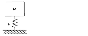
ここで、一般的な振動モデルは、図6のように表され、この振動モデルにおける固有振動周波数Fnは、次式で表される。なお、数式1中において、kは振動モデルにおける防振材のバネ定数、mは振動源の質量である。 Here, a general vibration model is represented as shown in FIG. 6, and the natural vibration frequency Fn in this vibration model is represented by the following equation. In Equation 1, k is the spring constant of the vibration isolator in the vibration model, and m is the mass of the vibration source.

Figure 0006935812
なお、バネ定数kは、振動モデルを構成する振動対象、本実施形態の場合はゴムブロック33の材料で決まるヤング率に振動対象の面積を掛け算し、振動対象の厚み、換言すれば高さで割った値として定義される。
Figure 0006935812
The spring constant k is calculated by multiplying the Young's modulus determined by the vibration target constituting the vibration model, or the material of the rubber block 33 in the case of the present embodiment, by the area of the vibration target, and the thickness of the vibration target, in other words, the height. Defined as a divided value.

図5に示したタイヤ3の振動モデルにおいては、質量Mtが質量Mbよりも十分に大きく、バネ定数Ktの方がバネ定数Kbよりも十分に大きくなっている。このため、実質的に質量Mtおよびバネ定数Kbのみを考慮して、図6に示した一般的な振動モデルと見做すことができる。つまり、数式1の質量mおよびバネ定数kを、それぞれ、図5における質量Mtおよびバネ定数Kbに置き換えることができる。そして、ゴムブロック33が摩耗して高さが低くなると、それに伴って質量Mbが小さくなり、バネ定数Kbが大きくなる。この場合、質量Mtはあまり変化せず、バネ定数Kbが大きくなったことを想定すると、数式1で示される固有振動周波数Fnが増加する。 In the vibration model of the tire 3 shown in FIG. 5, the mass Mt is sufficiently larger than the mass Mb, and the spring constant Kt is sufficiently larger than the spring constant Kb. Therefore, it can be regarded as a general vibration model shown in FIG. 6 in consideration of only the mass Mt and the spring constant Kb. That is, the mass m and the spring constant k in Equation 1 can be replaced with the mass Mt and the spring constant Kb in FIG. 5, respectively. When the rubber block 33 is worn and the height is lowered, the mass Mb is reduced and the spring constant Kb is increased accordingly. In this case, the mass Mt does not change so much, and assuming that the spring constant Kb becomes large, the natural vibration frequency Fn shown by Equation 1 increases.

このように、タイヤ3の踏み込み領域や蹴り出し領域での振動レベルの周波数特性は、ゴムブロック33を含むタイヤ3の振動特性に基づいて決まり、ゴムブロック33を含むタイヤ3の固有振動周波数Fnにおいて振動レベルがピークとなる。そして、この固有振動周波数Fnは、ゴムブロック33が摩耗して高さが低くなるほど増加する。例えば図7に示すようにタイヤ3が新品で溝深さが8mmの場合には固有振動周波数Fnが1.0kHz、タイヤ3が摩耗して溝深さが1.6mmの場合には固有振動周波数Fnが1.5kHzとなった。この固有振動周波数Fnは、タイヤ3の材質などによって異なった値になるが、タイヤ3の材質にかかわらず、タイヤ3が摩耗するほど固有振動周波数Fnが増加する。 As described above, the frequency characteristic of the vibration level in the stepping region and the kicking region of the tire 3 is determined based on the vibration characteristic of the tire 3 including the rubber block 33, and at the natural vibration frequency Fn of the tire 3 including the rubber block 33. The vibration level peaks. The natural vibration frequency Fn increases as the rubber block 33 wears and the height becomes lower. For example, as shown in FIG. 7, when the tire 3 is new and the groove depth is 8 mm, the natural vibration frequency Fn is 1.0 kHz, and when the tire 3 is worn and the groove depth is 1.6 mm, the natural vibration frequency Fn became 1.5 kHz. The natural vibration frequency Fn has a different value depending on the material of the tire 3 and the like, but regardless of the material of the tire 3, the natural vibration frequency Fn increases as the tire 3 wears.

したがって、タイヤ3の交換目安となる溝深さを決めておき、タイヤ3の溝深さが交換目安になったときの固有振動周波数Fnを特定周波数とし、それ以上の周波数帯を特定周波数帯として、フィルタ部13bで抽出できるようにしている。例えば、タイヤ3の交換推奨溝深さが3.0mmとされており、その深さをタイヤ3の交換目安となる溝深さとする場合には、フィルタ部13bで例えば1.5kHz以上の高周波数帯の成分を抽出すれば良い。 Therefore, the groove depth that serves as a guideline for replacing the tire 3 is determined, the natural vibration frequency Fn when the groove depth of the tire 3 serves as a guideline for replacement is set as a specific frequency, and a frequency band higher than that is set as a specific frequency band. , The filter unit 13b enables extraction. For example, if the recommended groove depth for replacement of the tire 3 is 3.0 mm and the depth is used as the groove depth as a guideline for replacement of the tire 3, the filter unit 13b has a high frequency of, for example, 1.5 kHz or more. The components of the band may be extracted.

積分演算部13cは、フィルタ部13bで抽出された特定周波数帯における振動レベルのレベル値を演算するレベル演算部に相当する部分であり、振動レベルに対応する摩耗データを生成する。ここでは、積分演算部13cにて、特定周波数帯における振動レベルのレベル値の積分値を演算し、これを摩耗データとしている。レベル値の演算については、タイヤ3の1回転分の検出信号から演算しても良いが、タイヤ3の複数回転分の検出信号の積算値として演算しても良く、その積算値をタイヤ3の回転数で割った平均値として演算しても良い。 The integration calculation unit 13c is a part corresponding to the level calculation unit that calculates the level value of the vibration level in the specific frequency band extracted by the filter unit 13b, and generates wear data corresponding to the vibration level. Here, the integral calculation unit 13c calculates the integral value of the level value of the vibration level in the specific frequency band, and uses this as wear data. The level value may be calculated from the detection signal for one rotation of the tire 3, or may be calculated as the integrated value of the detection signals for a plurality of rotations of the tire 3, and the integrated value may be calculated for the tire 3. It may be calculated as an average value divided by the number of rotations.

上記したように、タイヤ3の摩耗に応じて固有振動周波数Fnが増加する。そして、同じ周波数で見ると、振動センサ部11の検出信号の振動レベルは、タイヤ3の摩耗が大きくなるほど大きくなる。したがって、タイヤ3の摩耗状態に応じて、特定周波数帯での振動レベルのレベル値に差が生じ、その積分値についても差が生じることになる。 As described above, the natural vibration frequency Fn increases with the wear of the tire 3. Then, when viewed at the same frequency, the vibration level of the detection signal of the vibration sensor unit 11 increases as the wear of the tire 3 increases. Therefore, a difference occurs in the level value of the vibration level in the specific frequency band depending on the wear state of the tire 3, and a difference also occurs in the integrated value thereof.

参考として、タイヤ3の摩耗状態に応じて振動センサ部11の検出信号や振動レベルがどのように変化するかについて調べた。なお、路面の凹凸に基づく振動の影響を排除すべく、平坦路面を走行している場合の測定結果としている。図8は、タイヤ3が新品で溝深さが8mmのときと摩耗が進んで溝深さが1.6mmとなったときの振動センサ部11の検出信号を示している。図9は、タイヤ3の溝深さが8mm、3mm、1.6mmのときの振動スペクトル、本実施形態の場合は加速度スペクトルの周波数特性を示したものである。図9については、タイヤ3の1回転分の振動スペクトルの周波数特性を示してあるが、タイヤ3の10回転分の振動スペクトルを取得し、それの平均値を求めることで1回転分の振動スペクトルとしてある。 As a reference, we investigated how the detection signal and the vibration level of the vibration sensor unit 11 change according to the wear state of the tire 3. In addition, in order to eliminate the influence of vibration due to the unevenness of the road surface, the measurement result is taken when traveling on a flat road surface. FIG. 8 shows the detection signals of the vibration sensor unit 11 when the tire 3 is new and the groove depth is 8 mm, and when the wear progresses and the groove depth becomes 1.6 mm. FIG. 9 shows the frequency characteristics of the vibration spectrum when the groove depths of the tire 3 are 8 mm, 3 mm, and 1.6 mm, and the acceleration spectrum in the case of the present embodiment. FIG. 9 shows the frequency characteristics of the vibration spectrum for one rotation of the tire 3, but the vibration spectrum for one rotation is obtained by acquiring the vibration spectrum for 10 rotations of the tire 3 and obtaining the average value thereof. There is.

図8に示されるように、タイヤ3が新品で摩耗しておらず溝深さが十分に有る場合には、振動センサ部11の検出信号の振動が小さいが、タイヤ3が摩耗して溝深さが少ない場合には、振動センサ部11の検出信号の振動が大きくなっている。また、図9に示されるように、振動センサ部11の検出信号の振動スペクトルについても、固有振動周波数Fn以上の周波数帯域において、タイヤ3の摩耗状態が進むほど、振動スペクトルが大きくなっていることが判る。このことからも、固有振動周波数Fn以上の特定周波数帯の振動レベルのレベル値、例えばその積算値を調べることで、タイヤ3の摩耗状態を検出できることが判る。 As shown in FIG. 8, when the tire 3 is new and not worn and has a sufficient groove depth, the vibration of the detection signal of the vibration sensor unit 11 is small, but the tire 3 is worn and the groove depth is sufficient. When the amount is small, the vibration of the detection signal of the vibration sensor unit 11 is large. Further, as shown in FIG. 9, regarding the vibration spectrum of the detection signal of the vibration sensor unit 11, the vibration spectrum becomes larger as the wear state of the tire 3 progresses in the frequency band above the natural vibration frequency Fn. I understand. From this, it can be seen that the wear state of the tire 3 can be detected by examining the level value of the vibration level in a specific frequency band equal to or higher than the natural vibration frequency Fn, for example, the integrated value thereof.

また、タイヤ3の種類を変えても、溝深さと特定周波数帯の振動レベルの積算値との関係が成り立つかについても調べた。図10は、その結果を示した図であり、1.5Hz以上の周波数帯域において振動センサ部11の検出信号の振動レベルの積算値を算出したものである。積算値についてはタイヤ3の10回転分を算出しており、各周波数について最高値と最低値を示すと共に中央値をプロットで示してある。 It was also investigated whether the relationship between the groove depth and the integrated value of the vibration level in the specific frequency band holds even if the type of the tire 3 is changed. FIG. 10 is a diagram showing the results, and is a calculation of the integrated value of the vibration level of the detection signal of the vibration sensor unit 11 in the frequency band of 1.5 Hz or higher. As for the integrated value, 10 rotations of the tire 3 are calculated, and the maximum value and the minimum value are shown for each frequency, and the median value is shown in a plot.

この図に示されるように、タイヤ3が種類Xの場合と種類Yの場合、いずれにおいても、溝深さが浅くなるほど、つまりタイヤ3の摩耗が進むほど、積分値が大きくなっている。このため、タイヤ3の種類にかかわらず、固有振動周波数Fn以上の特定周波数帯の振動レベルのレベル値、例えばその積算値を調べることで、タイヤ3の摩耗状態を検出することが可能となる。そして、例えば閾値を0.3[V]に設定しておけば、タイヤ3の溝深さが3mmになったと判定されたときに報知装置23より報知することができる。さらに、タイヤ3の交換目安となる閾値に加えて警告閾値を設定し、例えば警告閾値を0.42[V]に設定しておけば、タイヤ3の溝深さが1.6mmになったと判定されたときに報知装置23よりタイヤ3の交換が早急に必要であることを警告することができる。 As shown in this figure, in both the case where the tire 3 is of the type X and the case of the type Y, the integrated value becomes larger as the groove depth becomes shallower, that is, as the tire 3 wears. Therefore, regardless of the type of the tire 3, the wear state of the tire 3 can be detected by examining the level value of the vibration level in a specific frequency band equal to or higher than the natural vibration frequency Fn, for example, the integrated value thereof. Then, for example, if the threshold value is set to 0.3 [V], the notification device 23 can notify when it is determined that the groove depth of the tire 3 has reached 3 mm. Further, if a warning threshold value is set in addition to the threshold value as a guideline for tire 3 replacement, for example, if the warning threshold value is set to 0.42 [V], it is determined that the groove depth of the tire 3 has reached 1.6 mm. When this is done, the notification device 23 can warn that the tire 3 needs to be replaced immediately.

また、制御部13は、摩耗データの取得タイミングおよびデータ通信部14からのデータ送信を制御している。具体的には、制御部13は、タイヤ3の摩耗状態の検知を行いたいタイミングで波形取込部13a、フィルタ部13bおよび積分演算部13cを機能させ、振動センサ部11の検出信号の振動レベルと対応する摩耗データをデータ通信部14に伝えている。タイヤ3の種類や車両の車種、走行の仕方にも依るが、タイヤ3は一般的に5000kmの走行毎に1mm程度摩耗すると言われている。このため、ここでは、制御部13は、タイヤ3の回転数から車両の走行距離を算出し、1〜数百km走行する毎に、タイヤ3の摩耗状態の検知を行うようにしている。 Further, the control unit 13 controls the acquisition timing of wear data and the data transmission from the data communication unit 14. Specifically, the control unit 13 causes the waveform acquisition unit 13a, the filter unit 13b, and the integration calculation unit 13c to function at the timing when the wear state of the tire 3 is desired to be detected, and the vibration level of the detection signal of the vibration sensor unit 11. The corresponding wear data is transmitted to the data communication unit 14. Although it depends on the type of tire 3, the type of vehicle, and the way of running, it is generally said that the tire 3 wears about 1 mm for every 5000 km of running. Therefore, here, the control unit 13 calculates the mileage of the vehicle from the rotation speed of the tire 3 and detects the wear state of the tire 3 every time the vehicle travels for 1 to several hundred kilometers.

勿論、振動センサ部11の検出信号に基づいて車両が走行したことを検知したタイミングごとにタイヤ3の摩耗状態が検知されるようにしても良いし、制御部13にタイマを備えておいて、所定期間毎にタイヤ3の摩耗状態が検知されるようにしても良い。 Of course, the wear state of the tire 3 may be detected at each timing when it is detected that the vehicle has traveled based on the detection signal of the vibration sensor unit 11, or the control unit 13 may be provided with a timer. The wear state of the tire 3 may be detected at predetermined intervals.

データ通信部14は、車体側システム2との間において通信を行う第1データ通信部に相当する部分である。データ通信部14は、例えば、制御部13から摩耗データが伝えられると、そのタイミングでデータ送信を行う。データ通信部14からのデータ送信のタイミングについては、制御部13によって制御される。例えば摩耗データの場合、制御部13から車両が所定距離走行して摩耗データが送られてくるたびに、データ通信部14からのデータ送信が行われるようになっている。 The data communication unit 14 is a part corresponding to the first data communication unit that communicates with the vehicle body side system 2. For example, when the wear data is transmitted from the control unit 13, the data communication unit 14 transmits the data at that timing. The timing of data transmission from the data communication unit 14 is controlled by the control unit 13. For example, in the case of wear data, data is transmitted from the data communication unit 14 every time the vehicle travels a predetermined distance from the control unit 13 and wear data is sent.

なお、タイヤ側装置1には、ボタン電池などによって構成される図示しない電源部が備えられており、電源部からの電力供給に基づいて、各部が作動させられる。電源部は、例えばボタン電池等の電池で構成されるようになっている。 The tire-side device 1 is provided with a power supply unit (not shown) composed of a button battery or the like, and each unit is operated based on the power supply from the power supply unit. The power supply unit is configured to be composed of a battery such as a button battery.

続いて、車体側システム2について説明する。車体側システム2には、上記したように、受信機21、ブレーキECU22、報知装置23などが備えられている。 Subsequently, the vehicle body side system 2 will be described. As described above, the vehicle body side system 2 includes a receiver 21, a brake ECU 22, a notification device 23, and the like.

受信機21は、タイヤ側装置1より送信された摩耗データを受信し、タイヤ3の摩耗状態を検出する。具体的には、受信機21は、データ通信部21aと制御部21bとを有した構成とされている。 The receiver 21 receives the wear data transmitted from the tire side device 1 and detects the wear state of the tire 3. Specifically, the receiver 21 has a configuration including a data communication unit 21a and a control unit 21b.

データ通信部21aは、第2データ通信部を構成する部分であり、タイヤ側装置1のデータ通信部14より送信された摩耗データを受信し、制御部21bに伝える役割を果たす。 The data communication unit 21a is a part constituting the second data communication unit, and plays a role of receiving the wear data transmitted from the data communication unit 14 of the tire side device 1 and transmitting it to the control unit 21b.

制御部21bは、CPU、ROM、RAM、I/Oなどを備えたマイコンにより構成され、ROMなどに記憶されたプログラムに従って各種処理を行う。制御部21bには、摩耗判定部21baが備えられており、この摩耗判定部21baが摩耗データに基づいてタイヤ摩耗状態の判定に関する各種処理を行うことにより、タイヤ摩耗を検知している。 The control unit 21b is composed of a microcomputer equipped with a CPU, ROM, RAM, I / O, etc., and performs various processes according to a program stored in the ROM or the like. The control unit 21b is provided with a wear determination unit 21ba, and the wear determination unit 21ba detects tire wear by performing various processes related to determination of a tire wear state based on wear data.

本実施形態の場合、所定周波数帯でのレベル値の積分値を摩耗データとしているため、摩耗判定部21baは、その積分値に基づいてタイヤ摩耗状態を判定している。例えば、摩耗判定部21baは、積分値を実験等によって求めておいた閾値と比較することでタイヤ摩耗状態を判定している。例えば、閾値については、タイヤ3の交換目安となる溝深さと対応する積分値とすることができる。すなわち、タイヤ3の摩耗が進み、タイヤ3の溝深さが交換目安となる溝深さになったときに、振動センサ部11の検出信号に基づいて積分演算部13cで演算されると想定される積算値を閾値に設定してある。したがって、摩耗判定部21baは、摩耗データが示す積分値が閾値を超える場合に、タイヤ3の溝深さがタイヤ3の交換目安となる溝深さになったと想定されるタイヤ摩耗状態になったことを検知する。 In the case of the present embodiment, since the integrated value of the level values in the predetermined frequency band is used as the wear data, the wear determination unit 21ba determines the tire wear state based on the integrated value. For example, the wear determination unit 21ba determines the tire wear state by comparing the integrated value with a threshold value obtained by an experiment or the like. For example, the threshold value can be an integral value corresponding to the groove depth as a guideline for replacing the tire 3. That is, it is assumed that when the tire 3 is worn and the groove depth of the tire 3 reaches the groove depth as a reference for replacement, the integration calculation unit 13c calculates based on the detection signal of the vibration sensor unit 11. The integrated value is set as the threshold value. Therefore, when the integrated value indicated by the wear data exceeds the threshold value, the wear determination unit 21ba is in a tire wear state in which it is assumed that the groove depth of the tire 3 has reached the groove depth that serves as a guideline for replacing the tire 3. Detect that.

また、積分値が大きくなるほどタイヤ3の摩耗が進んでいることを示していることから、摩耗判定部21baにて、積分値の大きさに応じてタイヤ3の摩耗状態、換言すればタイヤ3の溝深さを判定することもできる。 Further, since it is shown that the wear of the tire 3 progresses as the integrated value becomes larger, the wear determination unit 21ba indicates that the wear state of the tire 3 is increased according to the magnitude of the integrated value, in other words, the tire 3 is worn. It is also possible to determine the groove depth.

なお、ここでは摩耗判定部21baは、積分値に基づいてタイヤ摩耗状態を判定しているが、積分値に限らず、特定周波数帯におけるタイヤ3の振動レベルのレベル値を用いて、例えば任意の周波数のレベル値に基づいてタイヤ摩耗状態を判定することができる。 Here, the wear determination unit 21ba determines the tire wear state based on the integrated value, but the tire wear state is not limited to the integrated value, and the level value of the vibration level of the tire 3 in a specific frequency band is used, for example, any arbitrary value. The tire wear condition can be determined based on the frequency level value.

また、摩耗判定部21baは、必要に応じて、タイヤ摩耗状態の検知結果を報知装置23に伝え、報知装置23よりタイヤ摩耗状態をドライバに伝える。これにより、ドライバはタイヤ3を交換するまでの間はタイヤ摩耗状態に対応した運転を心掛けるようになり、車両の危険性を回避することが可能となるし、摩耗したタイヤ3を適切に交換することが可能となる。 Further, the wear determination unit 21ba transmits the detection result of the tire wear state to the notification device 23 as necessary, and the notification device 23 notifies the driver of the tire wear state. As a result, the driver will try to drive in response to the tire wear state until the tire 3 is replaced, and it will be possible to avoid the danger of the vehicle, and the worn tire 3 will be replaced appropriately. It becomes possible.

また、摩耗判定部21baからブレーキECU22などの車両運動制御を実行するためのECUに対してタイヤ摩耗状態を伝えており、伝えられたタイヤ摩耗状態に基づいて車両運動制御が実行されるようにしている。 Further, the wear determination unit 21ba informs the ECU for executing vehicle motion control such as the brake ECU 22 of the tire wear state, so that the vehicle motion control is executed based on the transmitted tire wear state. There is.

ブレーキECU22は、様々なブレーキ制御を行う制動制御装置を構成するものであり、ブレーキ液圧制御用のアクチュエータを駆動することで自動的にブレーキ液圧を発生させ、ホイールシリンダを加圧して制動力を発生させる。また、ブレーキECU22は、各車輪の制動力を独立して制御することもできる。 The brake ECU 22 constitutes a braking control device that performs various brake controls. By driving an actuator for controlling the brake fluid pressure, the brake fluid pressure is automatically generated, and the wheel cylinder is pressurized to exert a braking force. To generate. Further, the brake ECU 22 can independently control the braking force of each wheel.

上記したように、ブレーキECU22には、摩耗判定部21baからタイヤ摩耗状態の判定結果が伝えられる。これに基づき、ブレーキECU22は、タイヤ摩耗状態に応じたブレーキ制御を行っている。具体的には、ブレーキECU22は、車両運動制御として、タイヤ3の摩耗が進んでいるほどブレーキが効きにくくなることを想定したブレーキ制御が実行されるようにする。例えば、ブレーキECU22は、自動運転などにおけるブレーキ制御であれば、ブレーキを掛けるタイミングをタイヤ3の摩耗状態が進むほど早めるというような制御を実行する。また、タイヤ3の摩耗が進むとスリップし易くなるため、ブレーキ力が高くなるとタイヤ3がスリップする可能性があることから、ブレーキECU22は、より早くから摩耗前よりも低いブレーキ力を発生させる制御を実行する。 As described above, the brake ECU 22 is informed of the tire wear state determination result from the wear determination unit 21ba. Based on this, the brake ECU 22 performs brake control according to the tire wear state. Specifically, the brake ECU 22 executes brake control on the assumption that the brakes are less effective as the tires 3 are worn out, as vehicle motion control. For example, in the case of brake control in automatic driving or the like, the brake ECU 22 executes control such that the timing of applying the brake is advanced as the wear state of the tire 3 progresses. Further, since the tire 3 is likely to slip as the wear progresses, the tire 3 may slip when the braking force is increased. Therefore, the brake ECU 22 controls to generate a lower braking force earlier than before the wear. Run.

報知装置23は、例えばメータ表示器などで構成され、ドライバに対して運転をより慎重に行う必要があるタイヤ摩耗状態であることの報知に用いられる。報知装置23をメータ表示器で構成する場合、ドライバが車両の運転中に視認可能な場所に配置され、例えば車両におけるインストルメントパネル内に設置される。メータ表示器は、受信機21からタイヤ摩耗状態を示すデータが伝えられると、その内容が把握できる態様で表示を行うことで、視覚的にドライバに対して報知することができる。報知装置23については、ブザーや音声案内装置などで構成することもできる。 The notification device 23 is composed of, for example, a meter display or the like, and is used to notify the driver that the tire is in a worn state, which requires more careful driving. When the notification device 23 is composed of a meter display, the driver is placed in a place where the driver can see while driving the vehicle, for example, in the instrument panel of the vehicle. When the receiver 21 transmits data indicating the tire wear state, the meter display can visually notify the driver by displaying the data in a manner in which the contents can be grasped. The notification device 23 can also be configured by a buzzer, a voice guidance device, or the like.

以上のようにして、本実施形態にかかるタイヤシステム100が構成されている。なお、車体側システム2を構成する各部は、例えばCAN(Controller Area Networkの略)通信などによる車内LAN(Local Area Networkの略)を通じて接続されている。このため、車内LANを通じて各部が互いに情報伝達できるようになっている。 As described above, the tire system 100 according to the present embodiment is configured. Each part constituting the vehicle body side system 2 is connected through an in-vehicle LAN (abbreviation of Local Area Network) by, for example, CAN (abbreviation of Controller Area Network) communication. Therefore, each part can transmit information to each other through the in-vehicle LAN.

このように構成されるタイヤシステム100では、上記したように、振動センサ部11の検出信号の振動レベルのレベル値に基づいてタイヤ3の摩耗状態を検知している。タイヤ3の摩耗により、ゴムブロック33が薄くなり、バネ定数Kbが大きくなることから、振動センサ部11の検出信号の高周波成分の振動レベルのレベル値が大きくなる。そして、振動センサ部11の検出信号の高周波成分の振動レベルについては、タイヤ3の1回転のどの部分においても、摩耗が進んだ後の方が摩耗前の新品の時よりも大きくなる。 In the tire system 100 configured as described above, as described above, the wear state of the tire 3 is detected based on the level value of the vibration level of the detection signal of the vibration sensor unit 11. Due to the wear of the tire 3, the rubber block 33 becomes thin and the spring constant Kb becomes large, so that the level value of the vibration level of the high frequency component of the detection signal of the vibration sensor unit 11 becomes large. The vibration level of the high-frequency component of the detection signal of the vibration sensor unit 11 is higher after the tire 3 is worn than when it is new before the wear, in any part of one rotation of the tire 3.

したがって、踏み込み領域や蹴り出し領域の加速度波形を的確に抽出する必要はなく、タイヤ3の1回転中の振動波形を取り込めば良い。そして、タイヤ3の1回転中の振動波形における特定周波数帯の振動レベルのレベル値に基づいて、的確にタイヤ摩耗状態を検知できる。これにより、より精度良くタイヤ摩耗状態を検知することが可能となる。 Therefore, it is not necessary to accurately extract the acceleration waveform in the stepping region and the kicking region, and it is sufficient to capture the vibration waveform during one rotation of the tire 3. Then, the tire wear state can be accurately detected based on the level value of the vibration level in the specific frequency band in the vibration waveform during one rotation of the tire 3. This makes it possible to detect the tire wear state with higher accuracy.

(第2実施形態)
第2実施形態について説明する。本実施形態は、第1実施形態に対して更に精度良くタイヤ摩耗状態を検知できるようにするものであり、その他については第1実施形態と同様であるため、第1実施形態と異なる部分についてのみ説明する。
(Second Embodiment)
The second embodiment will be described. This embodiment enables the tire wear state to be detected more accurately than the first embodiment, and is the same as the first embodiment except for the parts different from the first embodiment. explain.

図11に示すように、本実施形態では、受信機21の制御部21bに車両情報取得部21bbを備えている。車両情報取得部21bbは、車両の走行に関連する情報(以下、車両情報という)を取得するものである。タイヤ摩耗状態の検知を行う際には、できるだけ振動センサ部11の検出信号に車両の走行状態に起因する影響が現れていない状況であるのが好ましい。 As shown in FIG. 11, in the present embodiment, the control unit 21b of the receiver 21 is provided with the vehicle information acquisition unit 21bb. The vehicle information acquisition unit 21bb acquires information related to the traveling of the vehicle (hereinafter referred to as vehicle information). When detecting the tire wear state, it is preferable that the detection signal of the vibration sensor unit 11 does not show any influence due to the running state of the vehicle as much as possible.

したがって、本実施形態では、車両情報取得部21bbにて車両情報を取得し、振動センサ部11の検出信号に影響を及ぼすような走行状態である場合が除外されるように、送られてきた摩耗データからタイヤ摩耗状態の検知に有効なデータを選定する。これにより、より精度良く、タイヤ摩耗状態の検知が行われるようにする。 Therefore, in the present embodiment, the wear that has been sent so as to exclude the case where the vehicle information acquisition unit 21bb acquires the vehicle information and is in a running state that affects the detection signal of the vibration sensor unit 11. Select data that is effective in detecting tire wear conditions from the data. As a result, the tire wear state can be detected more accurately.

ここで、車両情報としては、例えば車速情報、加減速度情報、操舵情報、路面情報、タイヤ空気圧情報、荷重情報、天気情報、位置情報、温度情報などが挙げられる。これらの車両情報については、車両情報取得部21bbで少なくとも1つを取得すれば良いが、複数取得できるようにすると好ましい。 Here, examples of vehicle information include vehicle speed information, acceleration / deceleration information, steering information, road surface information, tire pressure information, load information, weather information, position information, temperature information, and the like. At least one of these vehicle information may be acquired by the vehicle information acquisition unit 21bb, but it is preferable that a plurality of such vehicle information can be acquired.

車速情報については、例えばメータ制御用の電子制御装置(以下、ECUという)などで取り扱っているため、車内LANなどを通じて、メータECUから車両情報取得部21bbに伝えることができる。加減速度情報については、エンジンECUなどで取り扱われているため、車内LANなどを通じて、メータECUから車両情報取得部21bbに伝えることができるし、車速情報が示す車速を時間微分することで取得することもできる。操舵情報については、ステアリングECUなどで取り扱われているため、車内LANなどを通じて、ステアリングECUから車両情報取得部21bbに伝えることができる。 Since the vehicle speed information is handled by, for example, an electronic control device for meter control (hereinafter referred to as an ECU), the vehicle information can be transmitted from the meter ECU to the vehicle information acquisition unit 21bb through an in-vehicle LAN or the like. Since the acceleration / deceleration information is handled by the engine ECU or the like, it can be transmitted from the meter ECU to the vehicle information acquisition unit 21bb through the in-vehicle LAN or the like, and can be acquired by time-differentiating the vehicle speed indicated by the vehicle speed information. You can also. Since the steering information is handled by the steering ECU or the like, it can be transmitted from the steering ECU to the vehicle information acquisition unit 21bb through the in-vehicle LAN or the like.

路面情報については、例えば車載カメラで得た路面画像の画像処理を行うことで取得したり、振動センサ部11の検出信号が路面状態も表していることを利用して、検出信号から得た路面データをタイヤ側装置1から取得し、これに基づいて検出したりできる。なお、路面状態の検出手法については、周知となっている手法、例えば、路面データからタイヤ振動の特徴量を取得し、サポートベクタなどの教師データと特徴量との類似度から路面状態を推定する手法などを適用できる。 The road surface information is acquired by performing image processing of the road surface image obtained by, for example, an in-vehicle camera, or the road surface obtained from the detection signal by utilizing the fact that the detection signal of the vibration sensor unit 11 also represents the road surface state. Data can be acquired from the tire side device 1 and detected based on this. As for the road surface condition detection method, a well-known method, for example, the feature amount of tire vibration is acquired from the road surface data, and the road surface state is estimated from the similarity between the teacher data such as the support vector and the feature amount. Techniques can be applied.

タイヤ空気圧情報については、例えばタイヤ空気圧モニタリングシステムのECU(以下、TPMS−ECUという)から得ることができる。例えば、タイヤ側装置1にタイヤ空気圧の測定機能を備えておき、それをTPMS−ECUに伝える構成とすることができ、TPMS−ECUで得られたタイヤ空気圧が車両情報取得部21bbに伝えられるようにできる。また、荷重情報については、図4に示した振動センサ部11の検出信号の振動波形の第1ピーク値と第2ピーク値との間がタイヤ3の接地長を示していることから、タイヤ空気圧と接地長とから算出することができる。また、サスペンションECUなどで荷重情報を取り扱っている場合には、そこから荷重情報を車両情報取得部21bbに伝えることもできる。 The tire pressure information can be obtained from, for example, the ECU of the tire pressure monitoring system (hereinafter referred to as TPMS-ECU). For example, the tire-side device 1 may be provided with a tire pressure measuring function and may be configured to transmit the tire pressure to the TPMS-ECU so that the tire pressure obtained by the TPMS-ECU is transmitted to the vehicle information acquisition unit 21bb. Can be done. Regarding the load information, since the ground contact length of the tire 3 is shown between the first peak value and the second peak value of the vibration waveform of the detection signal of the vibration sensor unit 11 shown in FIG. 4, the tire pressure. And the ground contact length. Further, when the suspension ECU or the like handles the load information, the load information can be transmitted to the vehicle information acquisition unit 21bb from there.

天気情報や位置情報、さらに温度情報については、例えばナビゲーションECUを通じて取得できる。 Weather information, location information, and temperature information can be acquired through, for example, a navigation ECU.

例えば、車速情報については、好ましい車速範囲においてタイヤ摩耗状態の検知が行われるようにするために用いることができる。振動センサ部11の検出信号の振動レベルは、車速が小さいと小さく、車速が大きいと大きくなる。このため、振動レベルが小さすぎず、大きすぎない車速のときにタイヤ摩耗状態の検知が行われるのが好ましい。したがって、車速情報に基づいて、車速が所定速度範囲、例えば40km/h±αの際にタイヤ摩耗状態の検知が行われるようにする。 For example, the vehicle speed information can be used to detect the tire wear state in a preferable vehicle speed range. The vibration level of the detection signal of the vibration sensor unit 11 is small when the vehicle speed is low, and high when the vehicle speed is high. Therefore, it is preferable that the tire wear state is detected when the vehicle speed is not too small and not too large. Therefore, based on the vehicle speed information, the tire wear state is detected when the vehicle speed is in a predetermined speed range, for example, 40 km / h ± α.

加減速度情報については、急加速時や急ブレーキ時ではないことの検出に用いている。急加速時や急ブレーキ時には、振動センサ部11の検出信号にその影響が現れ得る。したがって、例えば加減速度が所定値以下の際にタイヤ摩耗状態の検知が行われるようにする。 The acceleration / deceleration information is used to detect that it is not during sudden acceleration or sudden braking. At the time of sudden acceleration or sudden braking, the influence may appear in the detection signal of the vibration sensor unit 11. Therefore, for example, when the acceleration / deceleration is equal to or less than a predetermined value, the tire wear state is detected.

操舵情報については、例えば直進走行であることの検出に用いている。車両の旋回中などには、振動センサ部11の検出信号にその影響が現れ得る。したがって、例えば操舵角が所定値以下、好ましくは直進走行の際にタイヤ摩耗状態の検知が行われるようにする。 The steering information is used, for example, to detect that the vehicle is traveling straight. When the vehicle is turning, the influence may appear on the detection signal of the vibration sensor unit 11. Therefore, for example, the tire wear state is detected when the steering angle is equal to or less than a predetermined value, preferably when traveling straight ahead.

路面情報については、平坦路面であることの検出に用いている。例えば、雨天走行時にはタイヤ3がスリップすることがあるし、砂利道などの凹凸路面ではその凹凸による振動が発生し、振動センサ部11の検出信号に影響が現れ得る。したがって、例えばアスファルト路面のような平坦路で、かつ、ドライ路面を走行している際にタイヤ摩耗状態の検知が行われるようにする。 The road surface information is used to detect that the road surface is flat. For example, the tire 3 may slip when traveling in the rain, and vibration may occur due to the unevenness on an uneven road surface such as a gravel road, which may affect the detection signal of the vibration sensor unit 11. Therefore, the tire wear state is detected when traveling on a flat road such as an asphalt road surface and on a dry road surface.

タイヤ空気圧情報については、適正空気圧範囲であることの検出に用いている。タイヤ空気圧が高すぎると路面の凹凸の影響を大きく受けてタイヤ3が振動し易くなるし、タイヤ空気圧が低くなるとタイヤ3が振動し難くなる。このため、振動センサ部11の検出信号にタイヤ空気圧の影響が現れ得る。したがって、タイヤ空気圧が予め決められた適正空気圧範囲である際にタイヤ摩耗状態の検知が行われるようにする。 The tire pressure information is used to detect that the tire pressure is within the proper air pressure range. If the tire air pressure is too high, the tire 3 is likely to vibrate due to the influence of the unevenness of the road surface, and if the tire air pressure is low, the tire 3 is less likely to vibrate. Therefore, the influence of the tire pressure may appear on the detection signal of the vibration sensor unit 11. Therefore, the tire wear state is detected when the tire pressure is within a predetermined appropriate air pressure range.

荷重情報については、荷重が掛かりすぎていないこと、具体的には過積載時ではないことの検出に用いている。過積載時には、通常時と比較してタイヤ3の振動特性が変化し得る。したがって、荷重が予め決められた適正荷重範囲である際にタイヤ摩耗状態の検知が行われるようにする。 The load information is used to detect that the load is not overloaded, specifically, that it is not overloaded. At the time of overloading, the vibration characteristics of the tire 3 may change as compared with the normal time. Therefore, the tire wear state is detected when the load is within a predetermined appropriate load range.

天気情報については、タイヤ摩耗状態の検知に適さない環境、例えば降雨、積雪、凍結などの状況ではないことの検出に用いている。降雨、積雪、凍結などの際にはタイヤ3のスリップなどが発生し、振動センサ部11の検出信号に影響が現れ得る。したがって、例えばスリップの影響が発生しにくいドライ路になっていると想定される晴天時に、タイヤ摩耗状態の検知が行われるようにする。 The weather information is used to detect that the environment is not suitable for detecting the tire wear state, such as rain, snow, or freezing. When it rains, snows, freezes, etc., the tire 3 slips, which may affect the detection signal of the vibration sensor unit 11. Therefore, for example, the tire wear state is detected when the road is sunny, which is assumed to be a dry road where the influence of slip is unlikely to occur.

位置情報については、坂道や工事中の路面のようにタイヤ摩耗状態の検知に適さない場所を走行中であることの検出や、高速道路のようにタイヤ摩耗状態の検知に適した場所を走行中であることの検出に用いている。タイヤ摩耗状態の検知は、一定速度で安定した走行が行われる際に実施されるのが好ましい。したがって、坂道や工事中ではない平坦な舗装道路、好ましくは高速道路の走行中にタイヤ摩耗状態の検知が行われるようにする。 Regarding location information, we are driving in a place that is not suitable for detecting tire wear, such as a slope or a road surface under construction, or in a place that is suitable for detecting tire wear, such as an expressway. It is used to detect that. It is preferable that the tire wear state is detected when stable running is performed at a constant speed. Therefore, tire wear conditions should be detected while driving on slopes, flat paved roads that are not under construction, preferably highways.

なお、位置情報については、天気情報との組み合わせとして使用することもできる。すなわち、天気情報は、地域毎に出されることから、位置情報から車両の走行場所を特定し、その走行場所の地域の天気を天気情報から取得するようにすれば、より正確な天気情報に基づいてタイヤ摩耗状態の検知が行われるようにすることができる。 The location information can also be used in combination with the weather information. That is, since the weather information is issued for each area, if the driving place of the vehicle is specified from the position information and the weather in the area of the driving place is acquired from the weather information, it is based on more accurate weather information. It is possible to detect the tire wear state.

温度情報については、タイヤ摩耗状態の検知に適さない温度であることの検出に用いている。ゴム製品であるタイヤ3は、高温になると柔らかくなり、バネ特性が変化してしまい、タイヤ摩耗状態の検知に適さない状況になり得る。したがって、外気温が所定温度以上であると、タイヤ摩耗状態の検知が行われないようにする。 The temperature information is used to detect that the temperature is not suitable for detecting the tire wear state. The tire 3, which is a rubber product, becomes soft at a high temperature, and the spring characteristics change, which may result in a situation unsuitable for detecting a tire wear state. Therefore, if the outside air temperature is equal to or higher than the predetermined temperature, the tire wear state is not detected.

このように、車両情報取得部21bbにて車両情報を取得し、車両情報に基づいて、より適した条件のときに、タイヤ摩耗状態の検知が行われるようにすることができる。すなわち、タイヤ側装置1から摩耗データが送られてきたときに、車両情報取得部21bbで取得した車両状態に基づいて、送られてきた摩耗データからタイヤ摩耗状態の検知に有効なデータを選定することができる。例えば、所定速度範囲内において、直進一定速度で車両が走行している際の摩耗データのように、特にタイヤ摩耗状態の検知に有効と考えられるデータを選定できる。これにより、さらに精度良くタイヤ摩耗状態を検知することが可能となる。 In this way, the vehicle information acquisition unit 21bb can acquire vehicle information, and based on the vehicle information, the tire wear state can be detected under more suitable conditions. That is, when wear data is sent from the tire side device 1, data effective for detecting the tire wear state is selected from the sent wear data based on the vehicle state acquired by the vehicle information acquisition unit 21bb. be able to. For example, it is possible to select data that is considered to be particularly effective for detecting a tire wear state, such as wear data when a vehicle is traveling at a constant straight speed within a predetermined speed range. This makes it possible to detect the tire wear state with higher accuracy.

なお、タイヤ摩耗を的確に検知できるように、例えば車速が所定速度範囲内のときにタイヤ摩耗検知が行われるようにする場合、タイヤ側装置1でその条件を満たす場合にのみ摩耗データを送信するようにしても良い。例えば、タイヤ側装置1では、車速推定部12で車速を算出できることから、算出された車速が所定速度範囲内のときにのみ、波形取込部13aによる振動センサ部11の検出信号の取込みが行われるようにする。このようにすれば、タイヤ摩耗状態の検知に適した場合に摩耗データが送信されるようにでき、より精度良くタイヤ摩耗状態を検知できるのに加えて、送信頻度を減らすことが可能となって、電力消費量の低減を図る事も可能となる。 In order to accurately detect tire wear, for example, when tire wear is detected when the vehicle speed is within a predetermined speed range, wear data is transmitted only when the condition is satisfied by the tire side device 1. You may do so. For example, in the tire-side device 1, since the vehicle speed estimation unit 12 can calculate the vehicle speed, the waveform acquisition unit 13a captures the detection signal of the vibration sensor unit 11 only when the calculated vehicle speed is within the predetermined speed range. To be heard. In this way, wear data can be transmitted when it is suitable for detecting the tire wear state, and in addition to being able to detect the tire wear state more accurately, it is possible to reduce the transmission frequency. It is also possible to reduce power consumption.

(第3実施形態)
第3実施形態について説明する。本実施形態は、第1、第2実施形態に対してタイヤ摩耗状態の初期設定を行えるようにしたものであり、その他については第1、第2実施形態と同様であるため、第1、第2実施形態と異なる部分についてのみ説明する。なお、ここでは第1実施形態に対して本実施形態の構成を適用した場合を例に挙げて説明するが、第2実施形態に対しても適用可能である。
(Third Embodiment)
A third embodiment will be described. In this embodiment, the tire wear state can be initially set for the first and second embodiments, and the other aspects are the same as those in the first and second embodiments. Therefore, the first and second embodiments are used. Only the parts different from the two embodiments will be described. Although the case where the configuration of the present embodiment is applied to the first embodiment will be described here as an example, it can also be applied to the second embodiment.

図12に示すように、本実施形態では、制御部21bに初期値設定部21bcを備えている。初期値設定部21bcは、タイヤ摩耗状態の初期値を設定するものである。 As shown in FIG. 12, in the present embodiment, the control unit 21b is provided with an initial value setting unit 21bc. The initial value setting unit 21bc sets the initial value of the tire wear state.

第1実施形態で説明したが、図10に示されるように、タイヤ3の種類に応じてタイヤ3の溝深さ毎の積分値に差があるため、多種に対応できる閾値や警報閾値の設定が難しいこともあり得る。これを考慮すると、振動レベルのレベル値、ここでは積分値について、摩耗前のタイヤ3のタイヤ摩耗状態に相当する値、すなわちタイヤ3が新品のときのタイヤ摩耗状態に相当する値を初期値として、それに基づいて規格化を行うのが好ましい。 Although described in the first embodiment, as shown in FIG. 10, since there is a difference in the integrated value for each groove depth of the tire 3 depending on the type of the tire 3, the threshold value and the alarm threshold value that can correspond to various types are set. Can be difficult. Considering this, the level value of the vibration level, here the integrated value, is set to the value corresponding to the tire wear state of the tire 3 before wear, that is, the value corresponding to the tire wear state when the tire 3 is new, as the initial value. , It is preferable to perform standardization based on it.

図13は、タイヤ3が新品で溝深さが8mmのときの積分値を基準として規格化を行った規格化積分値を求めたものである。具体的には、タイヤ3が新品のときの積分値を1とし、溝深さ毎の積分値の変化量に比例して、この変化量が大きいほど大きな値となるような規格化積分値としている。この図に示すように、タイヤ3の種類にかかわらず、タイヤ3の溝深さ毎の規格化積分値がほぼ同じ値になった。 FIG. 13 shows a standardized integrated value obtained by standardizing the integrated value when the tire 3 is new and the groove depth is 8 mm. Specifically, the integrated value when the tire 3 is new is set to 1, and the standardized integrated value is such that the larger the amount of change is, the larger the value is proportional to the amount of change in the integrated value for each groove depth. There is. As shown in this figure, the normalized integral value for each groove depth of the tire 3 is almost the same regardless of the type of the tire 3.

したがって、初期値設定部21bcにて、タイヤ3が新品のときに得られた積分値を初期値として設定し、摩耗判定部21baにて、タイヤ摩耗状態の検知の際に得られた積分値を初期値に対する相対変化として表される規格化積分値として求めるようにする。このようにすれば、規格化積分値を閾値や警報閾値と比較することで、タイヤ3の種類にかかわらず、より精度良くタイヤ摩耗状態を検知することが可能となる。 Therefore, the initial value setting unit 21bc sets the integrated value obtained when the tire 3 is new as the initial value, and the wear determination unit 21ba sets the integrated value obtained when the tire wear state is detected. It is calculated as a normalized integral value expressed as a relative change with respect to the initial value. By doing so, by comparing the standardized integral value with the threshold value and the alarm threshold value, it is possible to detect the tire wear state more accurately regardless of the type of the tire 3.

(第4実施形態)
第4実施形態について説明する。本実施形態は、第1〜第3実施形態に対してタイヤ3のゴム劣化に基づく補正を行うようにしたものであり、その他については第1〜第3実施形態と同様であるため、第1〜第3実施形態と異なる部分についてのみ説明する。
(Fourth Embodiment)
A fourth embodiment will be described. In this embodiment, the first to third embodiments are corrected based on the deterioration of the rubber of the tire 3, and the other parts are the same as those in the first to third embodiments. -Only the part different from the third embodiment will be described.

上記第1〜第3実施形態では、タイヤ3の摩耗によってゴムブロック33が薄くなり、バネ定数Kbが変化することで振動センサ部11の検出信号の高周波成分の振動レベルが変わることに基づいてタイヤ摩耗状態を検知している。しかしながら、タイヤ3はゴム製品であり、ゴム劣化に伴ってゴムブロック33のバネ定数Kbが変化し、タイヤ摩耗状態を的確に検知できなくなる可能性がある。 In the first to third embodiments, the rubber block 33 becomes thin due to wear of the tire 3, and the spring constant Kb changes, so that the vibration level of the high-frequency component of the detection signal of the vibration sensor unit 11 changes. The wear condition is detected. However, since the tire 3 is a rubber product, the spring constant Kb of the rubber block 33 may change as the rubber deteriorates, and the tire wear state may not be accurately detected.

タイヤ3が新品のときと3年相当の紫外線照射を行った紫外線劣化品それぞれについて、ゴムブロック33を切り出してロードセルにて荷重を加え、レーザ変位計を用いてゴムブロック33の変位を計測することでバネ定数Kbや積分値の変化を調べた。図14Aおよび図14Bは、その結果を示している。図14Aに示されるように、紫外線劣化品についてはバネ定数Kbが10%程度増加していた。このように、光照射などによるゴム劣化に起因してバネ定数Kbが高くなることで振動センサ部11の検出信号の振動レベルが高くなる。そして、図14Bに示すように、新品時と比較してゴム劣化時には積分値が20%程度増加しており、タイヤ3の溝深さに換算すると1mm程度誤検出してしまうことが確認された。このため、本実施形態では、ゴム劣化に対応した補正を行う。以下、図15を参照して本実施形態のタイヤ摩耗検知装置について説明する。 The rubber block 33 is cut out, a load is applied by a load cell, and the displacement of the rubber block 33 is measured using a laser displacement meter for each of the new tire 3 and the ultraviolet-deteriorated product that has been irradiated with ultraviolet rays equivalent to 3 years. The changes in the spring constant Kb and the integrated value were investigated in. 14A and 14B show the results. As shown in FIG. 14A, the spring constant Kb of the ultraviolet-deteriorated product increased by about 10%. As described above, the spring constant Kb becomes high due to the deterioration of the rubber due to light irradiation or the like, so that the vibration level of the detection signal of the vibration sensor unit 11 becomes high. Then, as shown in FIG. 14B, it was confirmed that the integrated value increased by about 20% when the rubber deteriorated as compared with the new product, and erroneous detection was performed by about 1 mm when converted to the groove depth of the tire 3. .. Therefore, in the present embodiment, the correction corresponding to the rubber deterioration is performed. Hereinafter, the tire wear detection device of the present embodiment will be described with reference to FIG.

図15に示すように、本実施形態のタイヤ摩耗検知装置では、車体側システム2における受信機21の制御部21bに時間推定部21bdを備え、時間推定部21bdに情報取得部24からの情報が入力されるようになっている。また、タイヤ側装置1の制御部13に定数補正部13dを備えている。また、タイヤ側装置1のデータ通信部14と車体側システム2のデータ通信部21aは双方向通信が行えるようにされている。 As shown in FIG. 15, in the tire wear detection device of the present embodiment, the control unit 21b of the receiver 21 in the vehicle body side system 2 is provided with the time estimation unit 21b, and the time estimation unit 21bd receives information from the information acquisition unit 24. It is supposed to be entered. Further, the control unit 13 of the tire side device 1 is provided with a constant correction unit 13d. Further, the data communication unit 14 of the tire-side device 1 and the data communication unit 21a of the vehicle body-side system 2 are capable of bidirectional communication.

時間推定部21bdは、情報取得部24からの情報に基づいて、光照射累計時間を推定する。情報取得部24は光照射累計時間の推定に用いられる情報を取得するものであり、日射センサの検出信号情報、カメラの画像情報、地図情報、天気情報、時刻情報、車両の向き情報、タイヤ位置情報の少なくとも1つが該当する。例えば、日射センサの検出信号情報を用いて光照射累計時間を推定する場合には、日射センサが情報取得部24に該当する。カメラ画像情報を用いて光照射累計時間を推定する場合には、カメラが情報取得部24に該当する。地図情報、天気情報、時刻情報、車両の向き情報を用いて光照射累計時間を推定する場合には、ナビゲーションシステムなどが情報取得部24に該当する。 The time estimation unit 21b estimates the cumulative light irradiation time based on the information from the information acquisition unit 24. The information acquisition unit 24 acquires information used for estimating the cumulative light irradiation time, such as detection signal information of the solar radiation sensor, camera image information, map information, weather information, time information, vehicle orientation information, and tire position. At least one piece of information is applicable. For example, when estimating the cumulative light irradiation time using the detection signal information of the solar radiation sensor, the solar radiation sensor corresponds to the information acquisition unit 24. When estimating the cumulative light irradiation time using the camera image information, the camera corresponds to the information acquisition unit 24. When estimating the cumulative light irradiation time using map information, weather information, time information, and vehicle orientation information, a navigation system or the like corresponds to the information acquisition unit 24.

日射センサの検出信号情報は、日射状態を示していることから、日射センサの検出信号情報に基づいて時間推定部21bdにて光照射累計時間が推定される。カメラの画像情報は、天候を示す情報であるため、画像情報に基づき時間推定部21bdにて例えば晴天のときの累計時間から光照射累計時間を推定される。地図情報は、例えば駐車場が屋内と屋外のいずれであるかという情報や、天気情報および時刻情報と共に、駐車もしくは走行している場所の天候に関する情報となる。このため、地図情報、天気情報、時刻情報に基づいて、時間推定部21bdにて光照射累計時間が推定される。また、車両の向きやタイヤ情報は、タイヤ位置を示す情報となる。例えば、晴天であってもタイヤ位置によって光の照射量が異なってくる。このため、時間推定部21bdは、車両の向きおよびタイヤ情報から、例えば晴天時の光照射累計時間を南側のタイヤ3に適用し、北側のタイヤ3については南側のタイヤ3の光照射累計時間を減らすように補正することで、各タイヤ3の光照射累計時間を推定する。 Since the detection signal information of the solar radiation sensor indicates the solar radiation state, the time estimation unit 21bd estimates the cumulative light irradiation time based on the detection signal information of the solar radiation sensor. Since the image information of the camera is information indicating the weather, the time estimation unit 21db estimates the cumulative light irradiation time from the cumulative time in fine weather, for example, based on the image information. The map information is, for example, information on whether the parking lot is indoors or outdoors, weather information, and time information, as well as information on the weather of the place where the parking lot is parked or traveled. Therefore, the cumulative light irradiation time is estimated by the time estimation unit 21bd based on the map information, the weather information, and the time information. Further, the vehicle orientation and tire information are information indicating the tire position. For example, even in fine weather, the amount of light irradiation differs depending on the tire position. Therefore, the time estimation unit 21bd applies, for example, the cumulative light irradiation time in fine weather to the tire 3 on the south side from the direction of the vehicle and the tire information, and applies the cumulative light irradiation time of the tire 3 on the south side to the tire 3 on the north side. By correcting to reduce, the cumulative light irradiation time of each tire 3 is estimated.

このようにして、時間推定部21bdにて光照射累計時間が推定されると、その推定結果を示す情報がデータ通信部21aを通じてタイヤ側装置1に送信される。そして、その推定結果を示す情報がデータ通信部14を通じて、タイヤ側装置1で受信されるようになっている。 When the cumulative light irradiation time is estimated by the time estimation unit 21bd in this way, information indicating the estimation result is transmitted to the tire side device 1 through the data communication unit 21a. Then, the information indicating the estimation result is received by the tire side device 1 through the data communication unit 14.

定数補正部13dは、車体側システム2から送られてきた光照射累計時間の推定結果を示す情報に基づいてフィルタ部13bにおけるフィルタ定数の補正値を算出する。タイヤ3のゴム劣化時における振動センサ部11の検出信号から得られる振動スペクトルはゴムブロック33のバネ定数の変化が支配的に影響しており、バネ定数Kbの1/2乗倍で振動スペクトルのシフト量が推定できる。したがって、予め光照射累計時間に対するバネ定数の変化率を実験などで調べておき、その関係を示す関数式やマップなどを定数補正部13dで保有しておけば、定数補正部13dは、その関数式やマップを用いて、光照射累計時間に対応する補正値を決定できる。具体的には、光照射累計時間が長くなるほど、カットオフ周波数が高くなる補正が行われるようにする。 The constant correction unit 13d calculates the correction value of the filter constant in the filter unit 13b based on the information indicating the estimation result of the cumulative light irradiation time sent from the vehicle body side system 2. The vibration spectrum obtained from the detection signal of the vibration sensor unit 11 when the rubber of the tire 3 deteriorates is dominated by the change in the spring constant of the rubber block 33, and the vibration spectrum is calculated by multiplying the spring constant Kb by 1/2. The shift amount can be estimated. Therefore, if the rate of change of the spring constant with respect to the cumulative light irradiation time is investigated in advance by an experiment or the like, and a function formula or a map showing the relationship is held in the constant correction unit 13d, the constant correction unit 13d will use the function. The correction value corresponding to the cumulative light irradiation time can be determined by using an equation or a map. Specifically, the longer the cumulative light irradiation time, the higher the cutoff frequency will be corrected.

例えば、関数式を用いる場合、光照射累計時間に対応するバネ定数変化分に対して、カットオフ周波数を1/2乗倍することでフィルタ定数を補正する。より詳しくは、図6に示す振動モデルを例に挙げて説明すると、固有振動周波数Fnが上記した数式1のように表され、タイヤ3のゴム劣化に伴ってバネ定数kが大きくなって、固有振動周波数Fnがバネ定数kの変化の平方根倍で変化する。このため、例えばフィルタ部13bのフィルタ定数を1.5kHzとした場合においてバネ定数kがゴム劣化によって新品時の1.1倍になった場合、固有振動周波数Fnも1.5×1.11/2倍し、その値をフィルタ定数として設定する。 For example, when a function formula is used, the filter constant is corrected by multiplying the cutoff frequency by 1/2 with respect to the change in the spring constant corresponding to the cumulative light irradiation time. More specifically, when the vibration model shown in FIG. 6 is taken as an example, the natural vibration frequency Fn is expressed as in the above equation 1, and the spring constant k increases as the rubber of the tire 3 deteriorates, which is unique. The vibration frequency Fn changes by multiplying the square root of the change of the spring constant k. Therefore, for example, when the filter constant of the filter unit 13b is 1.5 kHz and the spring constant k becomes 1.1 times that of a new product due to rubber deterioration, the natural vibration frequency Fn also becomes 1.5 × 1.1 1. Multiply by / 2 and set the value as a filter constant.

以上のようにして、本実施形態のタイヤ摩耗検知装置が構成されている。このような構成のタイヤ摩耗検知装置では、光照射累計時間に基づいてフィルタ部13bのフィルタ定数の補正値を行っている。このため、タイヤ3のゴム劣化に伴ってゴムブロック33のバネ定数Kbが変化しても、それに対応してフィルタ定数を補正できることから、タイヤ3の溝深さを誤検出することを抑制でき、より精度良くタイヤ摩耗状態を検知することが可能となる。 As described above, the tire wear detection device of the present embodiment is configured. In the tire wear detection device having such a configuration, the correction value of the filter constant of the filter unit 13b is performed based on the accumulated light irradiation time. Therefore, even if the spring constant Kb of the rubber block 33 changes due to the deterioration of the rubber of the tire 3, the filter constant can be corrected correspondingly, so that it is possible to suppress erroneous detection of the groove depth of the tire 3. It is possible to detect the tire wear state more accurately.

(第5実施形態)
第5実施形態について説明する。本実施形態も、第4実施形態と同様に、第1〜第3実施形態に対してタイヤ3のゴム劣化に基づく補正を行うようにしたものであるが、本実施形態では、フィルタ定数では無く積分演算部13cでの積分値について補正する。その他については第4実施形態と同様であるため、第4実施形態と異なる部分についてのみ説明する。
(Fifth Embodiment)
A fifth embodiment will be described. In the present embodiment as well, as in the fourth embodiment, the correction based on the rubber deterioration of the tire 3 is performed for the first to third embodiments, but in the present embodiment, the correction is not performed by the filter constant. The integrated value in the integral calculation unit 13c is corrected. Since the other parts are the same as those in the fourth embodiment, only the parts different from the fourth embodiment will be described.

図16に示すように、本実施形態では、積分値の補正を行うための演算値補正部13eを備えている。演算値補正部13eは、車体側システム2から送られてきた時間推定部21bdでの光照射累計時間の推定結果を示す情報に基づいて積分演算部13cにおける演算値の補正値を算出する。 As shown in FIG. 16, the present embodiment includes a calculated value correction unit 13e for correcting the integrated value. The calculated value correction unit 13e calculates the corrected value of the calculated value in the integration calculation unit 13c based on the information indicating the estimation result of the cumulative light irradiation time in the time estimation unit 21bd sent from the vehicle body side system 2.

上記したように、タイヤ3のゴム劣化時にバネ定数Kbが高くなることで振動センサ部11の検出信号の振動レベルが高くなる。このため、第4実施形態のようにフィルタ定数の補正を行わない場合には、フィルタ部13bを通過する成分が多くなり、積分演算部13cでの積分値が高い値となってしまう。これを考慮して、積分演算部13cでの積分値を補正し、光照射累計時間が長くなるほど積分値が小さくなるように補正する。例えば、積分値に対して、1未満の補正係数を掛けることによって補正を行う。 As described above, when the rubber of the tire 3 deteriorates, the spring constant Kb increases, so that the vibration level of the detection signal of the vibration sensor unit 11 increases. Therefore, when the filter constant is not corrected as in the fourth embodiment, the number of components passing through the filter unit 13b increases, and the integral value in the integration calculation unit 13c becomes a high value. In consideration of this, the integrated value in the integration calculation unit 13c is corrected so that the integrated value becomes smaller as the cumulative light irradiation time becomes longer. For example, correction is performed by multiplying the integrated value by a correction coefficient less than 1.

なお、タイヤ3のゴム劣化時にフィルタ部13bを通過する成分がどのくらい増えるかについては、一義的に決まらない。このため、実験的に、新品時とゴム劣化後それぞれにおける積分値の差を同じ走行条件で調べておき、その実験結果に基づいて補正定数を決定すれば良い。 It should be noted that how much the component passing through the filter portion 13b increases when the rubber of the tire 3 deteriorates is not uniquely determined. Therefore, it is sufficient to experimentally investigate the difference between the integrated values when the product is new and after the rubber is deteriorated under the same running conditions, and determine the correction constant based on the experimental results.

以上説明したように、光照射累計時間に基づいて積分演算部13cでの積分値の補正を行っている。このようにしても、タイヤ3の溝深さを誤検出することを抑制でき、より精度良くタイヤ摩耗状態を検知することが可能となる。 As described above, the integration calculation unit 13c corrects the integration value based on the cumulative light irradiation time. Even in this way, it is possible to suppress erroneous detection of the groove depth of the tire 3, and it is possible to detect the tire wear state with higher accuracy.

(第6実施形態)
第6実施形態について説明する。本実施形態は、第1〜第5実施形態に対してタイヤ側装置1に備えられていた構成の一部を車体側システム2における受信機21に備えるようにしたものである。その他については第1〜第5実施形態と同様であるため、第1〜第5実施形態と異なる部分についてのみ説明する。
(Sixth Embodiment)
The sixth embodiment will be described. In the present embodiment, a part of the configuration provided in the tire-side device 1 with respect to the first to fifth embodiments is provided in the receiver 21 in the vehicle body-side system 2. Since the other parts are the same as those in the first to fifth embodiments, only the parts different from the first to fifth embodiments will be described.

図17に示すように、本実施形態では、タイヤ側装置1の制御部13に、波形取込部13aが備えられているものの、フィルタ部13bや積分演算部13cが備えられていない。一方、受信機21の制御部21bに、摩耗判定部21baに加えて、フィルタ部21beや積分演算部23bfを備えている。フィルタ部21beや積分演算部23bfについては、第1実施形態などで説明したフィルタ部13bや積分演算部13cと同様の機能を果たすものである。 As shown in FIG. 17, in the present embodiment, the control unit 13 of the tire-side device 1 is provided with the waveform capturing unit 13a, but is not provided with the filter unit 13b or the integration calculation unit 13c. On the other hand, the control unit 21b of the receiver 21 includes a filter unit 21be and an integration calculation unit 23bf in addition to the wear determination unit 21ba. The filter unit 21be and the integral calculation unit 23bf perform the same functions as the filter unit 13b and the integral calculation unit 13c described in the first embodiment and the like.

このような構成においては、タイヤ側装置1から、波形取込部13aで取り込まれた振動センサ部11の検出信号の生データがデータ通信部14を通じて車体側システム2に伝えられる。また、車体側システム2では、受信機21において、データ通信部21aを通じてタイヤ側装置1から送信された生データが受信され、フィルタ部21beにてフィルタリングされることで特定周波数帯の振動レベルが抽出される。そして、積分演算部23bfで抽出された振動レベルのレベル値の積分値が演算される。 In such a configuration, the raw data of the detection signal of the vibration sensor unit 11 captured by the waveform capturing unit 13a is transmitted from the tire side device 1 to the vehicle body side system 2 through the data communication unit 14. Further, in the vehicle body side system 2, the receiver 21 receives the raw data transmitted from the tire side device 1 through the data communication unit 21a, and is filtered by the filter unit 21be to extract the vibration level of the specific frequency band. Will be done. Then, the integrated value of the level value of the vibration level extracted by the integral calculation unit 23bf is calculated.

このように、タイヤ側装置1ではなく、車体側システム2側にフィルタ部21beや積分演算部23bfを備えることもできる。これによっても、上記各実施形態と同様の効果を得ることができる。なお、ここでは第2実施形態の構成に対する変更点として記載したが、第1実施形態のように車両情報取得部21bbを備えていないものや、第3〜第5実施形態のように初期値設定部21bc、時間推定部21bd、情報取得部24を備える構造としても良い。 As described above, the filter unit 21be and the integration calculation unit 23bf can be provided on the vehicle body side system 2 side instead of the tire side device 1. Also by this, the same effect as each of the above-described embodiments can be obtained. Although described here as changes to the configuration of the second embodiment, the ones that do not have the vehicle information acquisition unit 21bb as in the first embodiment and the initial value setting as in the third to fifth embodiments. The structure may include a unit 21bc, a time estimation unit 21bd, and an information acquisition unit 24.

(他の実施形態)
本開示は、上記した実施形態に準拠して記述されたが、当該実施形態に限定されるものではなく、様々な変形例や均等範囲内の変形をも包含する。加えて、様々な組み合わせや形態、さらには、それらに一要素のみ、それ以上、あるいはそれ以下、を含む他の組み合わせや形態をも、本開示の範疇や思想範囲に入るものである。
(Other embodiments)
Although the present disclosure has been described in accordance with the above-described embodiment, the present disclosure is not limited to the embodiment, and includes various modifications and modifications within an equal range. In addition, various combinations and forms, as well as other combinations and forms that include only one element, more, or less, are also within the scope of the present disclosure.

(1)例えば、上記各実施形態では、振動センサ部11にてタイヤ3の径方向の振動の大きさに応じた検出信号を出力させているが、これはタイヤ3の摩耗状態に応じて振動の変化が最も大きく現れる方向であるためである。しかしながら、タイヤ3の接線方向、幅方向についても、タイヤ3の摩耗状態に応じて振動が変化することから、振動センサ部11にて、タイヤ3の接線方向もしくは幅方向の振動の大きさに応じた検出信号を出力させ、それに基づいてタイヤ摩耗検知を行っても良い。 (1) For example, in each of the above embodiments, the vibration sensor unit 11 outputs a detection signal according to the magnitude of the radial vibration of the tire 3, but this vibrates according to the wear state of the tire 3. This is because the change in is the direction in which the change appears most. However, since the vibration changes in the tangential direction and the width direction of the tire 3 according to the wear state of the tire 3, the vibration sensor unit 11 responds to the magnitude of the vibration in the tangential direction or the width direction of the tire 3. The tire wear may be detected based on the output of the detection signal.

(2)また、上記各実施形態では、タイヤ3の摩耗状態の検知を1〜数百km走行する毎に実施することについて説明した。これも一例を示したに過ぎず、それよりも短距離毎に、もしくは長距離毎に、タイヤ3の摩耗状態の検知が実施されるようにしても良い。そして、タイヤ3の摩耗状態の検知を行う際には、タイヤ側装置1から摩耗データを1回のみ送信するのではなく、複数回送信するようにしても良い。 (2) Further, in each of the above-described embodiments, it has been described that the wear state of the tire 3 is detected every one to several hundred kilometers of travel. This is also only an example, and the wear state of the tire 3 may be detected every shorter distance or every longer distance. Then, when detecting the wear state of the tire 3, the wear data may be transmitted a plurality of times instead of being transmitted only once from the tire side device 1.

特に、第2実施形態においては、タイヤ側装置1から送られてきた摩耗データが有効なデータとして選定されなかった場合、その摩耗データに基づいてはタイヤ3の摩耗状態の検知が行われないことになる。このため、タイヤ側装置1から摩耗データが複数回送信されるようにし、いずれかの摩耗データに基づいてタイヤ3の摩耗状態の検知が行われるようにすると好ましい。さらに、複数回送信する場合であっても車両の走行状態が変化していないと、再び摩耗データが有効なデータとして選定されない可能性がある。このため、走行状態が異なる状態になっていることを想定して、摩耗データの取得および送信間隔を数百m〜数km毎とすると好ましい。 In particular, in the second embodiment, when the wear data sent from the tire side device 1 is not selected as valid data, the wear state of the tire 3 is not detected based on the wear data. become. Therefore, it is preferable that the wear data is transmitted from the tire side device 1 a plurality of times, and the wear state of the tire 3 is detected based on any of the wear data. Further, even when the data is transmitted a plurality of times, if the running state of the vehicle has not changed, the wear data may not be selected as valid data again. Therefore, assuming that the traveling states are different, it is preferable that the wear data acquisition and transmission interval is set to every several hundred meters to several kilometers.

(3)また、上記各実施形態では、タイヤ3の摩耗状態の検知結果を報知装置23より報知したり、ブレーキECU22に伝えることで車両運動制御に用いたりする場合について説明した。しかしながら、これも一例を示したに過ぎない。例えば、車体側システム2として、車両外部の通信媒体との間において通信を行うことができる車両通信装置を備え、この車両通信装置を通じて、携帯電話などの携帯機や通信センターなどに通知することもできる。携帯機へ通知を行えば、携帯機を通じてユーザにタイヤ3の交換を勧めることができる。通信センターへの通知を行えば、通信センターを通じてディーラ等の車両整備工場にタイヤ3の摩耗状態を通知することができる。それにより、車両整備工場からユーザに対してタイヤ3の交換の案内通知を行うこと等が可能となる。 (3) Further, in each of the above embodiments, a case where the detection result of the wear state of the tire 3 is notified from the notification device 23 or used for vehicle motion control by transmitting the detection result to the brake ECU 22 has been described. However, this is also just an example. For example, the vehicle body side system 2 is provided with a vehicle communication device capable of communicating with a communication medium outside the vehicle, and the vehicle communication device may be used to notify a portable device such as a mobile phone or a communication center. can. By notifying the portable device, it is possible to recommend the user to replace the tire 3 through the portable device. By notifying the communication center, it is possible to notify the vehicle maintenance shop such as a dealer through the communication center of the wear state of the tire 3. As a result, it becomes possible for the vehicle maintenance shop to notify the user of the tire 3 replacement guidance and the like.

(4)また、上記各実施形態では、車速推定部12が振動センサ部11の検出信号に基づいて車速を推定する場合について説明した。しかしながら、これも一例を示したに過ぎず、タイヤ側装置1と受信機21とによって双方向通信を可能とし、データ通信部14を通じて受信機21から車速に関するデータを取得することで、車速推定部12にて車速を推定するようにしても良い。その場合、受信機21から送られた車速に関するデータが示す車速がそのときの車速と推定されるため、車速推定部12は、車速に関するデータをそのまま波形取込部13aに伝え、波形取込部13aでの取込み範囲の設定に用いられるようにすれば良い。受信機21は、車速に関するデータとして、車両情報取得部21bbで車両情報として得た車速情報を用いれば良い。 (4) Further, in each of the above embodiments, a case where the vehicle speed estimation unit 12 estimates the vehicle speed based on the detection signal of the vibration sensor unit 11 has been described. However, this is also only an example, and the vehicle speed estimation unit enables bidirectional communication between the tire side device 1 and the receiver 21 and acquires data on the vehicle speed from the receiver 21 through the data communication unit 14. The vehicle speed may be estimated at 12. In that case, since the vehicle speed indicated by the vehicle speed data sent from the receiver 21 is estimated to be the vehicle speed at that time, the vehicle speed estimation unit 12 transmits the data related to the vehicle speed to the waveform acquisition unit 13a as it is, and the waveform acquisition unit 12 It may be used for setting the capture range in 13a. The receiver 21 may use the vehicle speed information obtained as the vehicle information by the vehicle information acquisition unit 21bb as the data related to the vehicle speed.

なお、上記第4、第5実施形態を含め、タイヤ側装置1と受信機21との間において双方向通信を行う場合、双方向通信の形態については様々なものを適用することができる。例えば、BLE(Bluetooth Low Energyの略)通信を含むブルートゥース通信、wifiなどの無線LAN(Local Area Networkの略)、Sub-GHz通信、ウルトラワイドバンド通信、ZigBeeなどを双方向通信として適用できる。なお、「ブルートゥース」は登録商標である。 When bidirectional communication is performed between the tire-side device 1 and the receiver 21, including the fourth and fifth embodiments, various forms of bidirectional communication can be applied. For example, Bluetooth communication including BLE (abbreviation of Bluetooth Low Energy) communication, wireless LAN (abbreviation of Local Area Network) such as wifi, Sub-GHz communication, ultra wideband communication, ZigBee, etc. can be applied as bidirectional communication. "Bluetooth" is a registered trademark.

さらに、タイヤ側装置1と受信機21との間において双方向通信を行える形態とする場合、第2実施形態のように、摩耗データを選定することを、摩耗データの作成タイミングの選定とすることができる。すなわち、車両情報取得部21bbで取得した車両情報に基づいて、受信機21側でタイヤ3の摩耗状態の検知に有効な走行状態であることを選定し、そのタイミングでタイヤ側装置1に対して摩耗データの要求信号を出力する。そして、タイヤ側装置1では、要求信号を受信したときに、摩耗データの送信が行われるようにする。このようにすれば、タイヤ3の摩耗状態の検知に有効な走行状態となっているときに摩耗データが受信機21に届けられるため、その摩耗データに基づいて、精度良くタイヤ3の摩耗状態を検知することが可能となる。 Further, in the case where bidirectional communication can be performed between the tire side device 1 and the receiver 21, the selection of wear data as in the second embodiment is the selection of the wear data creation timing. Can be done. That is, based on the vehicle information acquired by the vehicle information acquisition unit 21bb, it is selected on the receiver 21 side that the running state is effective for detecting the wear state of the tire 3, and at that timing, the tire side device 1 is subjected to. Outputs the wear data request signal. Then, the tire-side device 1 transmits the wear data when the request signal is received. In this way, the wear data is delivered to the receiver 21 when the running state is effective for detecting the wear state of the tire 3, so that the wear state of the tire 3 can be accurately determined based on the wear data. It becomes possible to detect.

(5)また、上記各実施形態では、複数のタイヤ3のそれぞれに対してタイヤ側装置1を備えるようにしたが、少なくとも1つに備えられていればよい。すなわち、タイヤ摩耗状態は、概ね複数のタイヤ3で同様になることから、少なくとも1つのタイヤ側装置1を備えるようにすれば、そこで作成される摩耗データに基づいてタイヤ摩耗状態を検出すれば、他のタイヤ3についても同様の摩耗状態と推定できる。 (5) Further, in each of the above-described embodiments, the tire-side device 1 is provided for each of the plurality of tires 3, but at least one of them may be provided. That is, since the tire wear state is substantially the same for a plurality of tires 3, if at least one tire side device 1 is provided, the tire wear state can be detected based on the wear data created there. It can be estimated that the other tires 3 are in the same wear state.

(6)また、上記第5実施形態では、積分演算部13cでの積分値を補正するように下が、摩耗判定部21baでの摩耗判定を行う際の閾値を補正することもできる。例えば、タイヤ3のゴム劣化を加味し、光照射累計時間が長くなるほど閾値を大きな値にすれば良い。その場合、車体側システム2において補正を行えるため、双方向通信によって光照射累計時間に関する情報を伝える必要はない。 (6) Further, in the fifth embodiment, the lower part can correct the threshold value when the wear determination unit 21ba performs the wear determination so as to correct the integral value in the integration calculation unit 13c. For example, the threshold value may be set to a larger value as the cumulative light irradiation time becomes longer in consideration of the rubber deterioration of the tire 3. In that case, since the correction can be performed by the vehicle body side system 2, it is not necessary to convey information on the cumulative light irradiation time by two-way communication.

(7)さらに、上記各実施形態では、摩耗判定部21baが受信機21に備えられている場合を例に挙げたが、タイヤ側装置1の制御部13に摩耗判定部も備えておき、タイヤ側装置1から摩耗判定部での判定結果のみを受信機21側に伝えるようにしても良い。 (7) Further, in each of the above embodiments, the case where the wear determination unit 21ba is provided in the receiver 21 has been described as an example, but the control unit 13 of the tire side device 1 is also provided with the wear determination unit, and the tire is provided. Only the determination result of the wear determination unit may be transmitted from the side device 1 to the receiver 21 side.

1 タイヤ側装置
2 車体側システム
3 タイヤ
11 振動センサ部
13、21b 制御部
21 受信機
21ba 摩耗判定部
21bb 車両情報取得部
21bc 初期値設定部
100 タイヤ摩耗検知装置
1 Tire side device 2 Body side system 3 Tire 11 Vibration sensor unit 13, 21b Control unit 21 Receiver 21ba Wear judgment unit 21bb Vehicle information acquisition unit 21bc Initial value setting unit 100 Tire wear detection device

Claims (13)

タイヤ摩耗状態を検出するタイヤ摩耗検知装置であって、
車両に備えられる複数のタイヤ(3)にそれぞれ配置され、前記タイヤの振動の大きさに応じた検出信号を出力する振動検出部(11)と、前記車両の速度である車速を推定する車速推定部(12)と、前記検出信号の波形に現れる前記タイヤの摩耗状態を示す摩耗データを生成する信号処理部(13)と、前記摩耗データを送信する第1データ通信部(14)と、を備えるタイヤ側装置(1)と、
車体側に備えられ、前記摩耗データを受信する第2データ通信部(21a)と、前記摩耗データに基づいてタイヤ摩耗状態を判定する摩耗判定部(21ba)を含む制御部(21b)と、を備える車体側システム(2)と、を有し、
前記信号処理部は、前記車速推定部で推定された前記車速に基づいて、前記検出信号の取込み範囲を決めて取込み、取り込んだ前記検出信号から前記タイヤのゴムブロックを含む前記タイヤの固有振動周波数に基づく所定周波数帯の振動レベルのレベル値を求めて前記摩耗データとするタイヤ摩耗検知装置。
It is a tire wear detection device that detects the tire wear state.
A vibration detection unit (11) that is arranged on each of a plurality of tires (3) provided in the vehicle and outputs a detection signal according to the magnitude of the vibration of the tire, and a vehicle speed estimation that estimates the vehicle speed, which is the speed of the vehicle. A unit (12), a signal processing unit (13) that generates wear data indicating the wear state of the tire appearing in the waveform of the detection signal, and a first data communication unit (14) that transmits the wear data. Tire side device (1) to be provided and
A second data communication unit (21a) provided on the vehicle body side for receiving the wear data, and a control unit (21b) including a wear determination unit (21ba) for determining a tire wear state based on the wear data. It has a vehicle body side system (2) and
The signal processing unit determines a capture range of the detection signal based on the vehicle speed estimated by the vehicle speed estimation unit and captures the detection signal, and from the captured detection signal, the natural vibration frequency of the tire including the rubber block of the tire. A tire wear detection device that obtains a level value of a vibration level in a predetermined frequency band based on the above and uses it as the wear data.
前記振動検出部は、前記検出信号として、前記タイヤの径方向と接線方向および幅方向のいずれかの振動に応じた信号を出力する請求項1に記載のタイヤ摩耗検知装置。 The tire wear detection device according to claim 1, wherein the vibration detection unit outputs a signal corresponding to vibration in any of the radial direction, the tangential direction, and the width direction of the tire as the detection signal. 前記制御部は、前記車両の走行状態にかかわる車両情報を取得する車両情報取得部(21bb)を有し、
前記摩耗判定部は、前記車両情報取得部が取得した前記車両情報と前記摩耗データとに基づいて、前記タイヤ摩耗状態を判定する請求項1または2に記載のタイヤ摩耗検知装置。
The control unit has a vehicle information acquisition unit (21bb) that acquires vehicle information related to the traveling state of the vehicle.
The tire wear detection device according to claim 1 or 2, wherein the wear determination unit determines the tire wear state based on the vehicle information acquired by the vehicle information acquisition unit and the wear data.
前記車両情報には、車速情報、加減速度情報、操舵情報、路面情報、タイヤ空気圧情報、荷重情報、天気情報、位置情報、温度情報の少なくとも1つが含まれ、前記車両情報に基づいて前記摩耗データから有効なデータを選定し、選定された有効な前記摩耗データに基づいて前記タイヤ摩耗状態を判定する請求項3に記載のタイヤ摩耗検知装置。 The vehicle information includes at least one of vehicle speed information, acceleration / deceleration information, steering information, road surface information, tire pressure information, load information, weather information, position information, and temperature information, and the wear data is based on the vehicle information. The tire wear detection device according to claim 3, wherein valid data is selected from the above and the tire wear state is determined based on the selected valid wear data. 前記信号処理部は、前記タイヤの振動波形を示す前記検出信号の取込みを行う波形取込部(13a)と、前記波形取込部が取り込んだ前記検出信号から前記所定周波数帯の振動成分を抽出するフィルタ部(13b)と、抽出された前記所定周波数帯の振動成分の振動レベルの積分値である積分したレベル値を演算する積分演算部(13c)と、を備え、前記積分したレベル値を前記摩耗データとしている請求項1ないし4のいずれか1つに記載のタイヤ摩耗検知装置。 The signal processing unit extracts the vibration component of the predetermined frequency band from the waveform capturing unit (13a) that captures the detection signal indicating the vibration waveform of the tire and the detection signal captured by the waveform capturing unit. A filter unit (13b) for calculating the integrated level value and an integration calculation unit (13c) for calculating an integrated level value which is an integrated value of the vibration levels of the extracted vibration components of the predetermined frequency band are provided, and the integrated level value is obtained. The tire wear detection device according to any one of claims 1 to 4, which is the wear data. 前記第1データ通信部と前記第2データ通信部とによって前記タイヤ側装置と前記車体側システムとの間の双方向通信が行われ、
前記車体側システムは、前記タイヤへの光照射累計時間を推定する時間推定部(21bd)を有し、該光照射累計時間に関する情報を前記タイヤ側装置に伝え、
前記タイヤ側装置は、前記光照射累計時間に基づいて前記フィルタ部のフィルタ定数を補正する定数補正部(13d)を有している請求項5に記載のタイヤ摩耗検知装置。
The first data communication unit and the second data communication unit perform bidirectional communication between the tire-side device and the vehicle body-side system.
The vehicle body side system has a time estimation unit (21db) for estimating the cumulative light irradiation time to the tire, and transmits information on the cumulative light irradiation time to the tire side device.
The tire wear detection device according to claim 5, wherein the tire-side device has a constant correction unit (13d) that corrects the filter constant of the filter unit based on the cumulative light irradiation time.
前記定数補正部は、前記フィルタ定数の補正として、前記光照射累計時間が長くなるほどカットオフ周波数を高くする補正を行う請求項6に記載のタイヤ摩耗検知装置。 The tire wear detection device according to claim 6, wherein the constant correction unit corrects the filter constant by increasing the cutoff frequency as the cumulative light irradiation time becomes longer. 前記第1データ通信部と前記第2データ通信部とによって前記タイヤ側装置と前記車体側システムとの間の双方向通信が行われ、
前記車体側システムは、前記タイヤへの光照射累計時間を推定する時間推定部(21bd)を有し、該光照射累計時間に関する情報を前記タイヤ側装置に伝え、
前記タイヤ側装置は、前記光照射累計時間に基づいて前記積分演算部の積分値を補正する演算値補正部(13e)を有している請求項5に記載のタイヤ摩耗検知装置。
The first data communication unit and the second data communication unit perform bidirectional communication between the tire-side device and the vehicle body-side system.
The vehicle body side system has a time estimation unit (21db) for estimating the cumulative light irradiation time to the tire, and transmits information on the cumulative light irradiation time to the tire side device.
The tire wear detection device according to claim 5, wherein the tire-side device has a calculation value correction unit (13e) that corrects an integral value of the integration calculation unit based on the cumulative light irradiation time.
前記演算値補正部は、前記積分値の補正として、前記光照射累計時間が長くなるほど前記積分値を小さくする補正を行う請求項8に記載のタイヤ摩耗検知装置。 The tire wear detection device according to claim 8, wherein the calculated value correction unit corrects the integrated value by reducing the integrated value as the cumulative light irradiation time becomes longer. 前記車体側システムは、前記タイヤへの光照射累計時間を推定する時間推定部(21bd)を有し、
前記摩耗判定部は、前記レベル値を閾値と比較することで前記タイヤ摩耗状態を判定するものであると共に、前記光照射累計時間に基づいて前記閾値を補正する請求項5に記載のタイヤ摩耗検知装置。
The vehicle body side system has a time estimation unit (21db) for estimating the cumulative time of light irradiation on the tires.
The tire wear detection unit according to claim 5, wherein the wear determination unit determines the tire wear state by comparing the level value with a threshold value, and corrects the threshold value based on the accumulated light irradiation time. Device.
前記車体側システムは、日射センサの検出信号情報、カメラの画像情報、地図情報、天気情報、時刻情報、車両の向き情報、タイヤ位置情報の少なくとも1つの情報を取得する情報取得部(24)を有し、
前記時間推定部は、前記情報取得部で取得した情報に基づいて前記光照射累計時間を推定する請求項6ないし10のいずれか1つに記載のタイヤ摩耗検知装置。
The vehicle body side system has an information acquisition unit (24) that acquires at least one piece of information such as detection signal information of a solar radiation sensor, image information of a camera, map information, weather information, time information, vehicle orientation information, and tire position information. Have and
The tire wear detection device according to any one of claims 6 to 10, wherein the time estimation unit estimates the cumulative light irradiation time based on the information acquired by the information acquisition unit.
前記摩耗判定部は、前記レベル値を閾値と比較することで前記タイヤ摩耗状態を判定する請求項1ないし5のいずれか1つに記載のタイヤ摩耗検知装置。 The tire wear detection device according to any one of claims 1 to 5, wherein the wear determination unit determines the tire wear state by comparing the level value with a threshold value. 前記制御部は、摩耗前の前記タイヤにおける前記レベル値に相当する値を初期値として設定する初期値設定部(21bc)を有し、
前記摩耗判定部は、前記摩耗データが示す前記レベル値を前記初期値に基づいて規格化し、該規格化したレベル値に基づいて、前記タイヤ摩耗状態を判定する請求項1ないし10のいずれか1つに記載のタイヤ摩耗検知装置。
The control unit has an initial value setting unit (21bc) that sets a value corresponding to the level value of the tire before wear as an initial value.
The wear determination unit standardizes the level value indicated by the wear data based on the initial value, and determines the tire wear state based on the standardized level value. The tire wear detection device described in 1.
JP2019224168A 2018-12-13 2019-12-12 Tire wear detector Active JP6935812B2 (en)

Priority Applications (2)

Application Number Priority Date Filing Date Title
PCT/JP2019/048739 WO2020122189A1 (en) 2018-12-13 2019-12-12 Tire wear detection device
US17/343,018 US20210291597A1 (en) 2018-12-13 2021-06-09 Tire wear detection apparatus

Applications Claiming Priority (4)

Application Number Priority Date Filing Date Title
JP2018233412 2018-12-13
JP2019061221 2019-03-27

Publications (3)

Publication Number Publication Date
JP2020164147A JP2020164147A (en) 2020-10-08
JP2020164147A5 JP2020164147A5 (en) 2021-02-12
JP6935812B2 true JP6935812B2 (en) 2021-09-15

Family

ID=72717100

Family Applications (1)

Application Number Title Priority Date Filing Date
JP2019224168A Active JP6935812B2 (en) 2018-12-13 2019-12-12 Tire wear detector

Country Status (3)

Country Link
US (1) US20210291597A1 (en)
JP (1) JP6935812B2 (en)
WO (1) WO2020122189A1 (en)

Families Citing this family (5)

* Cited by examiner, † Cited by third party
Publication number Priority date Publication date Assignee Title
JP7367404B2 (en) * 2019-09-04 2023-10-24 株式会社Soken tire equipment
US11879810B2 (en) * 2020-09-15 2024-01-23 International Business Machines Corporation Predicting tire imbalance and/or wheel misalignment
DE112021003824T5 (en) * 2020-10-08 2023-05-11 Alps Alpine Co., Ltd. tire information acquisition device
JP2022104251A (en) * 2020-12-28 2022-07-08 株式会社ブリヂストン Vehicle control device, vehicle control method, and tire testing system
JP2024046484A (en) * 2022-09-22 2024-04-03 住友ゴム工業株式会社 Tire condition monitoring system

Family Cites Families (13)

* Cited by examiner, † Cited by third party
Publication number Priority date Publication date Assignee Title
JP3095095B2 (en) * 1992-05-27 2000-10-03 株式会社デンソー Tire abnormal wear detection device
US6278361B1 (en) * 1999-12-03 2001-08-21 Trw Inc. System and method for monitoring vehicle conditions affecting tires
US6759952B2 (en) * 2001-07-06 2004-07-06 Trw Inc. Tire and suspension warning and monitoring system
JP2004175276A (en) * 2002-11-28 2004-06-24 Aisin Seiki Co Ltd Tire characteristic determination device
US7310044B2 (en) * 2004-05-17 2007-12-18 Denso Corporation Tire condition monitoring system and method
JP2006131137A (en) * 2004-11-08 2006-05-25 Denso Corp Signal processing device for vehicle
JP2007153034A (en) * 2005-12-01 2007-06-21 Toyota Motor Corp Tire abrasion state judging device
JP5072463B2 (en) * 2007-07-11 2012-11-14 株式会社ブリヂストン Tire wear detection method and tire wear detection device
JP5956250B2 (en) * 2012-05-24 2016-07-27 株式会社ブリヂストン Tire uneven wear detection method and tire uneven wear detection device
US9259976B2 (en) * 2013-08-12 2016-02-16 The Goodyear Tire & Rubber Company Torsional mode tire wear state estimation system and method
JP6650680B2 (en) * 2015-03-31 2020-02-19 株式会社ブリヂストン Tire wear estimation method and tire wear estimation device
US10830908B2 (en) * 2016-06-30 2020-11-10 Massachusetts Institute Of Technology Applying motion sensor data to wheel imbalance detection, tire pressure monitoring, and/or tread depth measurement
US20180154707A1 (en) * 2016-12-05 2018-06-07 The Goodyear Tire & Rubber Company Indirect tire pressure and wear state estimation system and method

Also Published As

Publication number Publication date
US20210291597A1 (en) 2021-09-23
WO2020122189A1 (en) 2020-06-18
JP2020164147A (en) 2020-10-08

Similar Documents

Publication Publication Date Title
JP6935812B2 (en) Tire wear detector
US20200346655A1 (en) Road surface state determination device and tire system including same
US11549809B2 (en) Road surface state determination device and tire system
JP7180354B2 (en) Tire wear detector
EP3121034B1 (en) Tread wear estimation system and method
JP5121452B2 (en) Road surface state estimation method, road surface state estimation tire, road surface state estimation device, and vehicle control device
US20150153266A1 (en) Determining a risk of aquaplaning
JP6614073B2 (en) Road surface condition estimation device
US11565705B2 (en) Road surface state determination device
CN111615479B (en) Tire system
JP2015530955A (en) Method, control device and system for determining tread depth of tire tread
KR101475578B1 (en) Tire state determination device
JP2007055284A (en) Road surface state estimation method, tire for road surface state estimation, road surface state estimation device and vehicle control device
US20200307327A1 (en) Determining a tire pressure status in a vehicle
WO2020054658A1 (en) Tire system
CN110709686B (en) Tire wear detection system for automated vehicles
CN112078587A (en) Tire condition determination system
WO2019142870A1 (en) Tire system
Erdogan New sensors and estimation systems for the measurement of tire-road friction coefficient and tire slip variables
JP5705051B2 (en) Road surface state estimation method and road surface state estimation device
CN115715257A (en) Enhanced tracking of tire tread wear
JP7388000B2 (en) Road surface friction coefficient prediction system
RU2792711C2 (en) Method for determining soil hardness
JP7338240B2 (en) Tire condition determination system
US20240025214A1 (en) Adjustment of indirectly determined values of a tire monitoring system

Legal Events

Date Code Title Description
A521 Written amendment

Free format text: JAPANESE INTERMEDIATE CODE: A523

Effective date: 20201222

A621 Written request for application examination

Free format text: JAPANESE INTERMEDIATE CODE: A621

Effective date: 20201222

TRDD Decision of grant or rejection written
A01 Written decision to grant a patent or to grant a registration (utility model)

Free format text: JAPANESE INTERMEDIATE CODE: A01

Effective date: 20210727

A61 First payment of annual fees (during grant procedure)

Free format text: JAPANESE INTERMEDIATE CODE: A61

Effective date: 20210809

R150 Certificate of patent or registration of utility model

Ref document number: 6935812

Country of ref document: JP

Free format text: JAPANESE INTERMEDIATE CODE: R150