JP6932056B2 - Switching regulator - Google Patents
Switching regulator Download PDFInfo
- Publication number
- JP6932056B2 JP6932056B2 JP2017196188A JP2017196188A JP6932056B2 JP 6932056 B2 JP6932056 B2 JP 6932056B2 JP 2017196188 A JP2017196188 A JP 2017196188A JP 2017196188 A JP2017196188 A JP 2017196188A JP 6932056 B2 JP6932056 B2 JP 6932056B2
- Authority
- JP
- Japan
- Prior art keywords
- voltage
- output
- circuit
- error
- input
- Prior art date
- Legal status (The legal status is an assumption and is not a legal conclusion. Google has not performed a legal analysis and makes no representation as to the accuracy of the status listed.)
- Active
Links
Images


Classifications
-
- H—ELECTRICITY
- H02—GENERATION; CONVERSION OR DISTRIBUTION OF ELECTRIC POWER
- H02M—APPARATUS FOR CONVERSION BETWEEN AC AND AC, BETWEEN AC AND DC, OR BETWEEN DC AND DC, AND FOR USE WITH MAINS OR SIMILAR POWER SUPPLY SYSTEMS; CONVERSION OF DC OR AC INPUT POWER INTO SURGE OUTPUT POWER; CONTROL OR REGULATION THEREOF
- H02M3/00—Conversion of dc power input into dc power output
- H02M3/02—Conversion of dc power input into dc power output without intermediate conversion into ac
- H02M3/04—Conversion of dc power input into dc power output without intermediate conversion into ac by static converters
- H02M3/10—Conversion of dc power input into dc power output without intermediate conversion into ac by static converters using discharge tubes with control electrode or semiconductor devices with control electrode
- H02M3/145—Conversion of dc power input into dc power output without intermediate conversion into ac by static converters using discharge tubes with control electrode or semiconductor devices with control electrode using devices of a triode or transistor type requiring continuous application of a control signal
- H02M3/155—Conversion of dc power input into dc power output without intermediate conversion into ac by static converters using discharge tubes with control electrode or semiconductor devices with control electrode using devices of a triode or transistor type requiring continuous application of a control signal using semiconductor devices only
- H02M3/156—Conversion of dc power input into dc power output without intermediate conversion into ac by static converters using discharge tubes with control electrode or semiconductor devices with control electrode using devices of a triode or transistor type requiring continuous application of a control signal using semiconductor devices only with automatic control of output voltage or current, e.g. switching regulators
- H02M3/158—Conversion of dc power input into dc power output without intermediate conversion into ac by static converters using discharge tubes with control electrode or semiconductor devices with control electrode using devices of a triode or transistor type requiring continuous application of a control signal using semiconductor devices only with automatic control of output voltage or current, e.g. switching regulators including plural semiconductor devices as final control devices for a single load
- H02M3/1588—Conversion of dc power input into dc power output without intermediate conversion into ac by static converters using discharge tubes with control electrode or semiconductor devices with control electrode using devices of a triode or transistor type requiring continuous application of a control signal using semiconductor devices only with automatic control of output voltage or current, e.g. switching regulators including plural semiconductor devices as final control devices for a single load comprising at least one synchronous rectifier element
-
- H—ELECTRICITY
- H02—GENERATION; CONVERSION OR DISTRIBUTION OF ELECTRIC POWER
- H02M—APPARATUS FOR CONVERSION BETWEEN AC AND AC, BETWEEN AC AND DC, OR BETWEEN DC AND DC, AND FOR USE WITH MAINS OR SIMILAR POWER SUPPLY SYSTEMS; CONVERSION OF DC OR AC INPUT POWER INTO SURGE OUTPUT POWER; CONTROL OR REGULATION THEREOF
- H02M3/00—Conversion of dc power input into dc power output
- H02M3/02—Conversion of dc power input into dc power output without intermediate conversion into ac
- H02M3/04—Conversion of dc power input into dc power output without intermediate conversion into ac by static converters
- H02M3/10—Conversion of dc power input into dc power output without intermediate conversion into ac by static converters using discharge tubes with control electrode or semiconductor devices with control electrode
- H02M3/145—Conversion of dc power input into dc power output without intermediate conversion into ac by static converters using discharge tubes with control electrode or semiconductor devices with control electrode using devices of a triode or transistor type requiring continuous application of a control signal
- H02M3/155—Conversion of dc power input into dc power output without intermediate conversion into ac by static converters using discharge tubes with control electrode or semiconductor devices with control electrode using devices of a triode or transistor type requiring continuous application of a control signal using semiconductor devices only
- H02M3/156—Conversion of dc power input into dc power output without intermediate conversion into ac by static converters using discharge tubes with control electrode or semiconductor devices with control electrode using devices of a triode or transistor type requiring continuous application of a control signal using semiconductor devices only with automatic control of output voltage or current, e.g. switching regulators
- H02M3/158—Conversion of dc power input into dc power output without intermediate conversion into ac by static converters using discharge tubes with control electrode or semiconductor devices with control electrode using devices of a triode or transistor type requiring continuous application of a control signal using semiconductor devices only with automatic control of output voltage or current, e.g. switching regulators including plural semiconductor devices as final control devices for a single load
-
- G—PHYSICS
- G05—CONTROLLING; REGULATING
- G05F—SYSTEMS FOR REGULATING ELECTRIC OR MAGNETIC VARIABLES
- G05F1/00—Automatic systems in which deviations of an electric quantity from one or more predetermined values are detected at the output of the system and fed back to a device within the system to restore the detected quantity to its predetermined value or values, i.e. retroactive systems
- G05F1/10—Regulating voltage or current
- G05F1/46—Regulating voltage or current wherein the variable actually regulated by the final control device is dc
- G05F1/461—Regulating voltage or current wherein the variable actually regulated by the final control device is dc using an operational amplifier as final control device
-
- H—ELECTRICITY
- H02—GENERATION; CONVERSION OR DISTRIBUTION OF ELECTRIC POWER
- H02M—APPARATUS FOR CONVERSION BETWEEN AC AND AC, BETWEEN AC AND DC, OR BETWEEN DC AND DC, AND FOR USE WITH MAINS OR SIMILAR POWER SUPPLY SYSTEMS; CONVERSION OF DC OR AC INPUT POWER INTO SURGE OUTPUT POWER; CONTROL OR REGULATION THEREOF
- H02M1/00—Details of apparatus for conversion
- H02M1/0045—Converters combining the concepts of switch-mode regulation and linear regulation, e.g. linear pre-regulator to switching converter, linear and switching converter in parallel, same converter or same transistor operating either in linear or switching mode
-
- H—ELECTRICITY
- H02—GENERATION; CONVERSION OR DISTRIBUTION OF ELECTRIC POWER
- H02M—APPARATUS FOR CONVERSION BETWEEN AC AND AC, BETWEEN AC AND DC, OR BETWEEN DC AND DC, AND FOR USE WITH MAINS OR SIMILAR POWER SUPPLY SYSTEMS; CONVERSION OF DC OR AC INPUT POWER INTO SURGE OUTPUT POWER; CONTROL OR REGULATION THEREOF
- H02M1/00—Details of apparatus for conversion
- H02M1/08—Circuits specially adapted for the generation of control voltages for semiconductor devices incorporated in static converters
- H02M1/088—Circuits specially adapted for the generation of control voltages for semiconductor devices incorporated in static converters for the simultaneous control of series or parallel connected semiconductor devices
-
- H—ELECTRICITY
- H02—GENERATION; CONVERSION OR DISTRIBUTION OF ELECTRIC POWER
- H02M—APPARATUS FOR CONVERSION BETWEEN AC AND AC, BETWEEN AC AND DC, OR BETWEEN DC AND DC, AND FOR USE WITH MAINS OR SIMILAR POWER SUPPLY SYSTEMS; CONVERSION OF DC OR AC INPUT POWER INTO SURGE OUTPUT POWER; CONTROL OR REGULATION THEREOF
- H02M3/00—Conversion of dc power input into dc power output
- H02M3/02—Conversion of dc power input into dc power output without intermediate conversion into ac
- H02M3/04—Conversion of dc power input into dc power output without intermediate conversion into ac by static converters
- H02M3/10—Conversion of dc power input into dc power output without intermediate conversion into ac by static converters using discharge tubes with control electrode or semiconductor devices with control electrode
- H02M3/145—Conversion of dc power input into dc power output without intermediate conversion into ac by static converters using discharge tubes with control electrode or semiconductor devices with control electrode using devices of a triode or transistor type requiring continuous application of a control signal
- H02M3/155—Conversion of dc power input into dc power output without intermediate conversion into ac by static converters using discharge tubes with control electrode or semiconductor devices with control electrode using devices of a triode or transistor type requiring continuous application of a control signal using semiconductor devices only
- H02M3/156—Conversion of dc power input into dc power output without intermediate conversion into ac by static converters using discharge tubes with control electrode or semiconductor devices with control electrode using devices of a triode or transistor type requiring continuous application of a control signal using semiconductor devices only with automatic control of output voltage or current, e.g. switching regulators
- H02M3/1563—Conversion of dc power input into dc power output without intermediate conversion into ac by static converters using discharge tubes with control electrode or semiconductor devices with control electrode using devices of a triode or transistor type requiring continuous application of a control signal using semiconductor devices only with automatic control of output voltage or current, e.g. switching regulators without using an external clock
-
- H—ELECTRICITY
- H02—GENERATION; CONVERSION OR DISTRIBUTION OF ELECTRIC POWER
- H02M—APPARATUS FOR CONVERSION BETWEEN AC AND AC, BETWEEN AC AND DC, OR BETWEEN DC AND DC, AND FOR USE WITH MAINS OR SIMILAR POWER SUPPLY SYSTEMS; CONVERSION OF DC OR AC INPUT POWER INTO SURGE OUTPUT POWER; CONTROL OR REGULATION THEREOF
- H02M1/00—Details of apparatus for conversion
- H02M1/0003—Details of control, feedback or regulation circuits
- H02M1/0012—Control circuits using digital or numerical techniques
-
- H—ELECTRICITY
- H02—GENERATION; CONVERSION OR DISTRIBUTION OF ELECTRIC POWER
- H02M—APPARATUS FOR CONVERSION BETWEEN AC AND AC, BETWEEN AC AND DC, OR BETWEEN DC AND DC, AND FOR USE WITH MAINS OR SIMILAR POWER SUPPLY SYSTEMS; CONVERSION OF DC OR AC INPUT POWER INTO SURGE OUTPUT POWER; CONTROL OR REGULATION THEREOF
- H02M1/00—Details of apparatus for conversion
- H02M1/0003—Details of control, feedback or regulation circuits
- H02M1/0025—Arrangements for modifying reference values, feedback values or error values in the control loop of a converter
-
- H—ELECTRICITY
- H02—GENERATION; CONVERSION OR DISTRIBUTION OF ELECTRIC POWER
- H02M—APPARATUS FOR CONVERSION BETWEEN AC AND AC, BETWEEN AC AND DC, OR BETWEEN DC AND DC, AND FOR USE WITH MAINS OR SIMILAR POWER SUPPLY SYSTEMS; CONVERSION OF DC OR AC INPUT POWER INTO SURGE OUTPUT POWER; CONTROL OR REGULATION THEREOF
- H02M3/00—Conversion of dc power input into dc power output
- H02M3/02—Conversion of dc power input into dc power output without intermediate conversion into ac
- H02M3/04—Conversion of dc power input into dc power output without intermediate conversion into ac by static converters
- H02M3/10—Conversion of dc power input into dc power output without intermediate conversion into ac by static converters using discharge tubes with control electrode or semiconductor devices with control electrode
- H02M3/145—Conversion of dc power input into dc power output without intermediate conversion into ac by static converters using discharge tubes with control electrode or semiconductor devices with control electrode using devices of a triode or transistor type requiring continuous application of a control signal
- H02M3/155—Conversion of dc power input into dc power output without intermediate conversion into ac by static converters using discharge tubes with control electrode or semiconductor devices with control electrode using devices of a triode or transistor type requiring continuous application of a control signal using semiconductor devices only
- H02M3/156—Conversion of dc power input into dc power output without intermediate conversion into ac by static converters using discharge tubes with control electrode or semiconductor devices with control electrode using devices of a triode or transistor type requiring continuous application of a control signal using semiconductor devices only with automatic control of output voltage or current, e.g. switching regulators
- H02M3/1566—Conversion of dc power input into dc power output without intermediate conversion into ac by static converters using discharge tubes with control electrode or semiconductor devices with control electrode using devices of a triode or transistor type requiring continuous application of a control signal using semiconductor devices only with automatic control of output voltage or current, e.g. switching regulators with means for compensating against rapid load changes, e.g. with auxiliary current source, with dual mode control or with inductance variation
Description
本発明は、スイッチングレギュレータに関する。 The present invention relates to a switching regulator.
図5に、従来のスイッチングレギュレータ500の回路図を示す。
FIG. 5 shows a circuit diagram of a
従来のスイッチングレギュレータ500は、電源端子501と、接地端子502と、基準電圧源510と、誤差増幅回路511と、基準電圧源512と、PFM比較回路513と、発振回路514と、PMOSトランジスタ530と、NMOSトランジスタ531と、インダクタ540と、容量541と、抵抗543及び544と、出力端子542と、電流電圧変換回路520、スロープ電圧生成回路521、PWM比較回路522、制御回路523、及び逆流検出回路524からなるPWM変換回路550とを備え、これらが図示のように接続されて構成されている(例えば、特許文献1参照)。
The
このような構成によって負帰還ループが機能し、スイッチングレギュレータ500は、出力端子542の電圧を抵抗543と抵抗544とで分圧した電圧VFBが基準電圧源510の基準電圧VREF1と等しくなるように動作して、出力端子542に所定の出力電圧VOUTを生成する。
With such a configuration, the negative feedback loop functions, and the
従来のスイッチングレギュレータ500では、PFM比較回路513が誤差増幅回路511の出力である誤差電圧VERRと基準電圧源512の基準電圧VREF2とを比較し、その出力である比較結果信号CMPFにより発振回路514をイネーブル又はディスエーブルさせてPWM動作とPFM動作を切り替える方式を採用することにより、出力端子542に接続される外部の負荷50に流れる負荷電流IOUTが小さいときにPFM動作に移行し、電力変換効率を向上させることを可能としている。
In the
しかしながら、上記のような従来のスイッチングレギュレータ500では、PFM動作中に負荷電流IOUTが急増すると出力電圧VOUTが大きく低下するという課題があった。
However, the
この原因は、一般に、スイッチングレギュレータにおける誤差増幅回路のゲインは非常に大きく設定されることから、PFM動作中、誤差増幅回路511の出力である誤差電圧VERRが0Vまで低下するためである。誤差電圧VERRが0Vまで低下してしまうことから、誤差電圧VERRが0Vから基準電圧VREF2を超えてPWM動作するまでに大幅な遅延が発生し、この間に出力電圧VOUTが大きく低下することとなる。
This is because the gain of the error amplifier circuit in the switching regulator is generally set to be very large, so that the error voltage VERR, which is the output of the
かかる原因について、以下、図6の波形図を用いて詳細に説明する。 The cause of this will be described in detail below with reference to the waveform diagram of FIG.
図6は、従来のスイッチングレギュレータ500における負荷電流IOUT、PMOSトランジスタ530のドレインから出力される電圧VSW、インダクタ540に流れるインダクタ電流IL、出力電圧VOUT、電圧VFB、誤差電圧VERR、比較結果信号CMPFの波形を示している。また、電圧VFBの波形に重ねて、基準電圧VREF1を一点差線で示し、誤差電圧VERRの波形に重ねて、基準電圧VREF2を一点差線で、0Vを点線で示している。
FIG. 6 shows the load current IOUT in the
時刻t0では、比較結果信号CMPFがハイレベルとなっており、スイッチングレギュレータ500は、PFM動作している。よって、PMOSトランジスタ530及びNMOSトランジスタ531は、スイッチング動作を停止してオフしている。この状態で、時刻t0において負荷電流IOUTが急増すると、これに従い、出力電圧VOUTが低下していき、電圧VFBも低下していく。そして、電圧VFBが基準電圧VREF1を下回ると、誤差電圧VERRが0Vから上昇し始める。その後、時刻t1において、誤差電圧VERRが基準電圧VREF2を上回ると、比較結果信号CMPFがローレベルに反転する。これにより、PMOSトランジスタ530及びNMOSトランジスタ531がスイッチング動作を開始し、インダクタ電流ILが流れて出力電圧VOUTが上昇に転じる。このように、時刻t0から時刻t1まで、すなわち、負荷電流IOUTが急増してからPMOSトランジスタ530及びNMOSトランジスタ531がスイッチング動作を開始するまでに遅延時間DTが発生する。したがって、出力電圧VOUTが大きく低下することとなる。
At time t0, the comparison result signal CMPF is at a high level, and the
本発明は、以上のような課題を解決するためになされたものであり、PFM動作中に負荷電流が急増しても、出力電圧の大幅な低下を抑制することが可能なスイッチングレギュレータを提供することを目的とする。 The present invention has been made to solve the above problems, and provides a switching regulator capable of suppressing a significant decrease in output voltage even if a load current suddenly increases during PFM operation. The purpose is.
本発明のスイッチングレギュレータは、電源端子に供給される電源電圧から出力端子に所定の出力電圧を生成するスイッチングレギュレータであって、一端が前記出力端子に接続されたインダクタと、前記電源端子と前記インダクタの他端との間に接続されたスイッチング素子と、前記出力電圧に基づく電圧と第1の基準電圧との差を増幅し、第1の誤差電圧を出力する第1の誤差増幅回路と、第1の入力ノードに入力される前記第1の誤差電圧と第2の入力ノードに入力される第2の基準電圧とに基づき出力ノードに第2の誤差電圧を生成するクランプ回路と、第1の入力端子に入力される前記第2の誤差電圧と第2の入力端子に入力される前記第2の基準電圧とを比較し、第1のレベルまたは第2のレベルの比較結果信号を出力するPFM比較回路と、前記比較結果信号が前記第1のレベルのとき所定周波数のクロック信号を出力し、前記比較結果信号が前記第2のレベルのとき前記クロック信号の出力を停止する発振回路と、前記第2の誤差電圧と前記発振回路の出力とに基づいて前記スイッチング素子を所望のパルス幅でオン・オフするPWM変換回路とを備え、前記クランプ回路は、入力が前記第1の入力ノードに接続され、出力が前記出力ノードに接続されたバッファ回路と、一端が前記出力ノードに接続され、定電圧を発生する定電圧発生部と、前記定電圧発生部の他端の電圧と前記第2の基準電圧との差を増幅する第2の誤差増幅回路と、第2の電源端子と前記第1の入力ノードとの間に接続され、ゲートが前記第2の誤差増幅回路の出力に接続されたMOSトランジスタとを有し、前記第2の誤差電圧の下限値を前記第2の基準電圧の電圧値から前記定電圧を減算した電圧値にクランプすることを特徴とする。
The switching regulator of the present invention is a switching regulator that generates a predetermined output voltage at an output terminal from a power supply voltage supplied to the power supply terminal, and is an inductor whose one end is connected to the output terminal, and the power supply terminal and the inductor. A first error amplifier circuit that amplifies the difference between the switching element connected to the other end of the output voltage, the voltage based on the output voltage, and the first reference voltage, and outputs the first error voltage. An amplifier circuit that generates a second error voltage at an output node based on the first error voltage input to the
本発明のスイッチングレギュレータによれば、PFM比較回路の第1の入力端子に入力される第2の誤差電圧の下限値が第2の基準電圧の電圧値から所定の電圧値を減算した電圧値にクランプされる。すなわち、PFM比較回路の第1の入力端子に入力される電圧の下限値を0Vよりも第2の基準電圧に近い電圧に設定することができる。これにより、PFM動作中に負荷電流が急増した場合でもPFM動作からPWM動作へ短時間で移行できる。したがって、出力電圧が大幅に低下することを抑制することが可能となる。 According to the switching regulator of the present invention, the lower limit of the second error voltage input to the first input terminal of the PFM comparison circuit is a voltage value obtained by subtracting a predetermined voltage value from the voltage value of the second reference voltage. Be clamped. That is, the lower limit of the voltage input to the first input terminal of the PFM comparison circuit can be set to a voltage closer to the second reference voltage than 0V. As a result, even if the load current suddenly increases during the PFM operation, the PFM operation can be shifted to the PWM operation in a short time. Therefore, it is possible to suppress a significant decrease in the output voltage.
以下、本発明の実施形態について、図面を参照して説明する。 Hereinafter, embodiments of the present invention will be described with reference to the drawings.
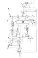
図1は、本発明の第1の実施形態のスイッチングレギュレータ100の回路図である。
FIG. 1 is a circuit diagram of a
本実施形態のスイッチングレギュレータ100は、電源電圧VDD1が供給される電源端子101と、電源電圧VDD2が供給される電源端子102と、接地端子103と、基準電圧源110と、誤差増幅回路111と、基準電圧源112と、PFM比較回路113と、発振回路114と、PMOSトランジスタ130(「スイッチング素子」ともいう)と、NMOSトランジスタ131(「同期整流素子」ともいう)と、インダクタ140と、容量141と、抵抗143及び144と、出力端子142と、電流電圧変換回路120、スロープ電圧生成回路121、PWM比較回路122、制御回路123、及び逆流検出回路124からなるPWM変換回路150と、クランプ回路160とを備えている。
The
クランプ回路160は、入力が入力ノードNI1に接続されたバッファ回路161と、一端がバッファ回路の出力及び出力ノードNOに接続された定電圧発生部162と、反転入力端子が定電圧発生部162の他端に接続され、非反転入力端子が入力ノードNI2に接続された誤差増幅回路163と、ゲートが誤差増幅回路163の出力に接続され、ドレインが電源端子102に接続され、ソースが入力ノードNI1に接続されたNMOSトランジスタ164とを有している。
The
基準電圧源110は、一端が誤差増幅回路111の非反転入力端子に接続され、他端が接地端子103に接続されている。誤差増幅回路111は、反転入力端子が抵抗143と抵抗144との接続点に接続され、出力がクランプ回路160の入力ノードNI1に接続されている。クランプ回路160は、入力ノードNI1が誤差増幅回路111の出力に接続され、入力ノードNI2が基準電圧源112の一端に接続され、出力ノードNOがPFM比較回路113の反転入力端子及びPWM比較回路122の反転入力端子に接続されている。基準電圧源112の一端は、PFM比較回路113の非反転入力端子に接続され、他端は接地端子103に接続されている。PFM比較回路113は、出力が発振回路114の入力に接続されている。発振回路114は、出力が制御回路123の入力に接続されている。
One end of the
スロープ電圧生成回路121は、入力が電流電圧変換回路120の出力に接続され、出力がPWM比較回路122の非反転入力端子に接続されている。PWM比較回路122は、出力が制御回路123の入力に接続されている。PMOSトランジスタ130は、ソースが電源端子101及び電流電圧変換回路120の入力に接続され、ゲートが制御回路123の出力に接続され、ドレインがインダクタ140の一端、逆流検出回路124の非反転入力端子、及びNMOSトランジスタ131のドレインに接続されている。NMOSトランジスタ131は、ゲートが制御回路123の出力に接続され、ソースが接地端子103に接続されている。逆流検出回路124は、反転入力端子が接地端子103に接続され、出力が制御回路123の入力に接続されている。
In the slope
インダクタ140は、他端が容量141の一端、抵抗143の一端、及び出力端子142に接続されている。容量141の他端は、接地端子103に接続されている。抵抗144の他端は、接地端子103に接続されている。
The other end of the
以下、上記のように構成されたスイッチングレギュレータ100の動作について説明する。
Hereinafter, the operation of the
誤差増幅回路111は、出力端子142の出力電圧VOUTを抵抗143と抵抗144とで分圧した電圧VFBと基準電圧源110の基準電圧VREF1とを比較して、誤差電圧VERR1を出力する。
The
クランプ回路160は、入力ノードNI1に入力される誤差電圧VERR1と入力ノードNI2に入力される基準電圧源112の基準電圧VREF2とに基づき、出力ノードNOに誤差電圧VERR2を生成する。具体的には、バッファ回路161の出力インピーダンスが誤差増幅回路111の出力インピーダンスよりも低く設定されており、バッファ回路161は、誤差電圧VERR1に比例した誤差電圧VERR2を出力ノードNOに生成する。定電圧発生部162は、定電圧VOSを生成する。誤差増幅回路163は、誤差電圧VERR2に定電圧VOSを加算した電圧VMと基準電圧VREF2とを比較してNMOSトランジスタ164のゲートに出力電圧を入力する。これにより、クランプ回路160は、電圧VMが基準電圧VREF2よりも小さいとき、誤差電圧VERR2を基準電圧VREF2よりも定電圧VOS分低い電圧にクランプする。
The
電流電圧変換回路120は、PMOSトランジスタ130のソース電流を電圧に変換し、スロープ電圧生成回路121に出力する。スロープ電圧生成回路121は、電流電圧変換回路120の出力にノコギリ波を加算し、電圧VCSを出力する。PWM比較回路122は、誤差電圧VERR2と電圧VCSとを比較し、比較結果信号CMPWを制御回路123に出力する。
The current-
PFM比較回路113は、基準電圧源112の基準電圧VREF2と誤差電圧VERR2とを比較し、比較結果信号CMPFを発振回路114に出力する。発振回路114は、比較結果信号CMPFがローレベルのとき、所定の周波数で発振し(イネーブルされ)、出力信号CLKとしてクロック信号を出力する。また、発振回路114は、比較結果信号CMPFがハイレベルのとき、発振を停止し(ディスエーブルされ)、出力信号CLKをローレベルに固定する。
The
逆流検出回路124は、NMOSトランジスタ131のドレイン電圧とソース電圧とを比較し、ドレイン電圧がソース電圧より高くなると、逆電流検出信号を制御回路123に出力する。
The
制御回路123は、入力された各信号に従って、PMOSトランジスタ130とNMOSトランジスタ131のオン・オフを制御する。
The
インダクタ140と容量141は、PMOSトランジスタ130のドレインから出力される電圧VSWを平滑する。
The
このような回路構成によって負帰還ループが機能し、スイッチングレギュレータ100は、電圧VFBが基準電圧VREF1と等しくなるように動作して、出力端子142に出力電圧VOUTを生成する。
With such a circuit configuration, the negative feedback loop functions, and the
スイッチングレギュレータ100では、出力端子142に接続される負荷10に流れる負荷電流IOUTの大きさによって、以下のように、PWM(Pulse Width Modulation)動作とPFM(Pulse Frequency Modulation)動作が切り替わる。
In the
負荷電流が大きい場合、出力電圧VOUTの低下を補うように誤差電圧VERR1、すなわち、誤差電圧VERR2が上昇する。したがって、誤差電圧VERR2が基準電圧VREF2よりも定常的に大きくなり、発振回路114は、出力信号CLKとして所定周波数のクロック信号を出力し続ける。このクロック信号の立ち上がりに同期して、PWM変換回路150は、PMOSトランジスタ130をオンさせ、NMOSトランジスタ131をオフさせる。このとき、PMOSトランジスタ130のオン時間を制御する信号のパルス幅は、PWM変換回路150により決定される。このように、負荷電流IOUTが大きい場合には、スイッチングレギュレータ100は、PWM動作となる。
When the load current is large, the error voltage VERR1, that is, the error voltage VERR2 increases so as to compensate for the decrease in the output voltage VOUT. Therefore, the error voltage VRR2 becomes constantly larger than the reference voltage VREF2, and the
その後、上述の状態から、負荷電流IOUTが小さくなった場合、負荷電流IOUTが小さくなってすぐの時点では、誤差電圧VERR2が基準電圧VREF2よりも定常的に大きい状態が続いている。しかし、負荷電流IOUTが小さくなっていることから、負荷電流IOUTによる出力電圧VOUTの低下が少ないため、PMOSトランジスタ130をオンさせることによる出力電圧VOUTの上昇が大きくなる。したがって、この出力電圧VOUTの上昇を補うように誤差電圧VERR2が低下し、基準電圧VREF2よりも低い電圧値となる。よって、PMOSトランジスタ130がオフとなり、出力電圧VOUTは、低下していく。
After that, when the load current IOUT becomes small from the above-mentioned state, the error voltage VERR2 continues to be steadily larger than the reference voltage VREF2 immediately after the load current IOUT becomes small. However, since the load current IOUT is small, the decrease in the output voltage VOUT due to the load current IOUT is small, and therefore the increase in the output voltage VOUT due to turning on the
そして、誤差電圧VERR2が上昇していき基準電圧VREF2よりも大きくなると、発振回路114は、出力信号CLKとしてクロック信号を出力する。このクロック信号の立ち上がりに同期して、PWM変換回路150は、PMOSトランジスタ130をオンさせ、NMOSトランジスタ131をオフさせる。このとき、負荷電流IOUTが小さいことから、PMOSトランジスタ130がオンしたことにより、出力電圧VOUTがすぐに所望の電圧値を上回るため、誤差電圧VERR2は低下する。すると、PWM変換回路150は、PMOSトランジスタ130をオフさせ、NMOSトランジスタ131をオンさせる。また、発振回路114は、出力信号CLKをローレベルに固定する。このように、負荷電流IOUTが小さい場合には、発振回路114は、発振と停止とを繰り返す。すなわち、スイッチングレギュレータ100は、PFM動作となる。
Then, when the error voltage VRR2 rises and becomes larger than the reference voltage VREF2, the
このようにして、本実施形態のスイッチングレギュレータ100は、負荷電流IOUTが小さいときにPFM動作に移行し、電力変換効率を向上させることができる。
In this way, the
かかる本実施形態のスイッチングレギュレータ100の特徴的な構成を説明するため、以下、スイッチングレギュレータ100がPFM動作しているときに、負荷電流IOUTが急増した場合の回路動作について詳述する。
In order to explain the characteristic configuration of the
図2は、本実施形態のスイッチングレギュレータ100における負荷電流IOUT、電圧VSW、インダクタ140に流れるインダクタ電流IL、出力電圧VOUT、電圧VFB、誤差電圧VERR2、比較結果信号CMPFの波形を示している。また、電圧VFBの波形に重ねて、基準電圧VREF1を一点差線で示し、誤差電圧VERR2の波形に重ねて、基準電圧VREF2を一点差線で、0Vを点線で示している。
FIG. 2 shows the waveforms of the load current IOUT, the voltage VSW, the inductor current IL flowing through the
時刻t0では、比較結果信号CMPFがハイレベルとなっており、スイッチングレギュレータ100は、PFM動作している。よって、PMOSトランジスタ130及びNMOSトランジスタ131は、スイッチング動作を停止してオフしている。このとき、電圧VFBが基準電圧VREF1より高いことから、誤差増幅回路111は、誤差電圧VERR1として低い電圧(0V)を出力しようとする。しかし、上述のとおり、クランプ回路160は、電圧VMが基準電圧VREF2より小さくなると、誤差電圧VERR2を基準電圧VREF2よりも定電圧VOS分低い電圧にクランプするため、誤差電圧VERR2(誤差電圧VERR1)は、基準電圧VREF2よりも低く、0Vよりも高い電圧となっている。
At time t0, the comparison result signal CMPF is at a high level, and the
上述の状態で、時刻t0において負荷電流IOUTが急増すると、これに従い、出力電圧VOUTが低下していき、電圧VFBも低下していく。そして、電圧VFBが基準電圧VREF1を下回ると、誤差電圧VERR2は、基準電圧よりも定電圧VOS分低い電圧から上昇し始める。 In the above state, when the load current IOUT suddenly increases at time t0, the output voltage VOUT decreases and the voltage VFB also decreases accordingly. Then, when the voltage VFB falls below the reference voltage VREF1, the error voltage VRR2 starts to rise from a voltage lower than the reference voltage by a constant voltage VOS.
その後、時刻t1において、誤差電圧VERR2が基準電圧VREF2を上回ると、比較結果信号CMPFがローレベルに反転する。これにより、PMOSトランジスタ130及びNMOSトランジスタ131がスイッチング動作を開始し、インダクタ電流ILが流れて出力電圧VOUTが上昇に転じる。
Then, at time t1, when the error voltage VRR2 exceeds the reference voltage VREF2, the comparison result signal CMPF is inverted to a low level. As a result, the
このように、本実施形態のスイッチングレギュレータ100は、誤差電圧VERR2の下限値が基準電圧VREF2の電圧値から定電圧VOS分を減算した電圧値にクランプされるように動作することにより、時刻t0から時刻t1まで、すなわち、PFM動作中に負荷電流IOUTが急増してからPWM動作に移行するまでに遅延時間DTを短縮することができる。したがって、出力電圧VOUTが大きく低下することを抑制することが可能となる。
As described above, the
次に、図3を参照して、本発明の第2の実施形態のスイッチングレギュレータ200について説明する。
Next, the
本実施形態のスイッチングレギュレータ200は、第1の実施形態のスイッチングレギュレータ100のクランプ回路160において、誤差増幅回路163の反転入力端子と出力ノードNOとの間に接続されていた定電圧発生部162が削除され、代わりに、バッファ回路161の出力と出力ノードNOとの間に定電圧発生部262が接続された構成となっている。その他の構成については、図1のスイッチングレギュレータ100と同一であるため、同一の構成要素には同一符号を付し、重複する説明は適宜省略する。
In the
上述の構成により、本実施形態のスイッチングレギュレータ200も、第1の実施形態のスイッチングレギュレータ100と同様、誤差電圧VERR2の下限値が基準電圧VREF2の電圧値から定電圧VOS分を減算した電圧値にクランプされるように動作する。これにより、PFM動作中に負荷電流IOUTが急増した場合でも、負荷電流IOUTが急増してからPWM動作に移行するまでの遅延時間DTを短縮し、出力電圧VOUTが大きく低下することを抑制することができる。
With the above configuration, the
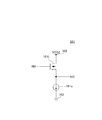
図4は、第1及び第2の実施形態におけるバッファ回路161の位置具体例を示している。バッファ回路161は、ドレインが電源端子102に接続され、ソースがクランプ回路160の出力ノードNOに接続され、ゲートがクランプ回路160の入力ノードNI1に接続されNMOSトランジスタ161tと、出力ノードNOと接地端子103との間に接続された定電流源161cとにより構成されている。すなわち、バッファ回路161は、ソースフォロワ回路で構成されている。
FIG. 4 shows a specific example of the position of the
かかる構成によれば、少ない素子数で出力インピーダンスの低いバッファ回路を実現することができる。 According to such a configuration, a buffer circuit having a low output impedance can be realized with a small number of elements.
以上、本発明の実施形態について説明したが、本発明は上記実施形態に限定されず、本発明の趣旨を逸脱しない範囲において種々の変更が可能であることは言うまでもない。 Although the embodiments of the present invention have been described above, it goes without saying that the present invention is not limited to the above embodiments and various modifications can be made without departing from the spirit of the present invention.
例えば、上記実施形態において、定電圧発生部162、262は、定電圧が生成可能であれば、その構成は特に限定されない。
For example, in the above embodiment, the configuration of the constant
また、上記実施形態においては、電流モード制御方式のスイッチングレギュレータを例として説明したが、本発明は、電圧モード制御方式のスイッチングレギュレータにも適用可能である。 Further, in the above embodiment, the current mode control type switching regulator has been described as an example, but the present invention can also be applied to the voltage mode control type switching regulator.
また、上記実施形態においては、スイッチング素子及び同期整流素子としてMOSトランジスタを用いた例を説明したが、バイポーラトランジスタ等を用いてもよい。 Further, in the above embodiment, the example in which the MOS transistor is used as the switching element and the synchronous rectifying element has been described, but a bipolar transistor or the like may be used.
また、上記実施形態においては、同期整流方式のスイッチングレギュレータを例として説明したが、本発明は、ダイオード整流方式のスイッチングレギュレータにも適用可能である。なお、ダイオード整流方式とした場合は、逆流検出回路は不要である。 Further, in the above embodiment, the synchronous rectification type switching regulator has been described as an example, but the present invention can also be applied to the diode rectification type switching regulator. When the diode rectification method is used, the backflow detection circuit is unnecessary.
100、200 スイッチングレギュレータ
101、102、501 電源端子
103、502 接地端子
110、112、510、512 基準電圧源
111、163、511 誤差増幅回路
113、513 PFM比較回路
114、514 発振回路
120、520 電流電圧変換回路
121、521 スロープ電圧生成回路
122、522 PWM比較回路
123、523 制御回路
124、524 逆流検出回路
130、530 PMOSトランジスタ
131、164、531 NMOSトランジスタ
140、540 インダクタ
141、541 容量
142、542 出力端子
143、144、543、544 抵抗
150、550 PWM変換回路
160 クランプ回路
161 バッファ回路
162、262 定電圧発生部
100, 200
Claims (4)
一端が前記出力端子に接続されたインダクタと、
前記第1の電源端子と前記インダクタの他端との間に接続されたスイッチング素子と、
前記出力電圧に基づく電圧と第1の基準電圧との差を増幅し、第1の誤差電圧を出力する第1の誤差増幅回路と、
第1の入力ノードに入力される前記第1の誤差電圧と第2の入力ノードに入力される第2の基準電圧とに基づき出力ノードに第2の誤差電圧を生成するクランプ回路と、
第1の入力端子に入力される前記第2の誤差電圧と第2の入力端子に入力される前記第2の基準電圧とを比較し、第1のレベルまたは第2のレベルの比較結果信号を出力するPFM比較回路と、
前記比較結果信号が前記第1のレベルのとき所定周波数のクロック信号を出力し、前記比較結果信号が前記第2のレベルのとき前記クロック信号の出力を停止する発振回路と、
前記第2の誤差電圧と前記発振回路の出力とに基づいて前記スイッチング素子を所望のパルス幅でオン・オフするPWM変換回路とを備え、
前記クランプ回路は、入力が前記第1の入力ノードに接続され、出力が前記出力ノードに接続されたバッファ回路と、
一端が前記出力ノードに接続され、定電圧を発生する定電圧発生部と、
前記定電圧発生部の他端の電圧と前記第2の基準電圧との差を増幅する第2の誤差増幅回路と、
第2の電源端子と前記第1の入力ノードとの間に接続され、ゲートが前記第2の誤差増幅回路の出力に接続されたMOSトランジスタとを有し、
前記第2の誤差電圧の下限値を前記第2の基準電圧の電圧値から前記定電圧を減算した電圧値にクランプすることを特徴とするスイッチングレギュレータ。 A switching regulator that generates a predetermined output voltage from the power supply voltage supplied to the first power supply terminal to the output terminal.
With an inductor whose one end is connected to the output terminal,
A switching element connected between the first power supply terminal and the other end of the inductor,
A first error amplifier circuit that amplifies the difference between the voltage based on the output voltage and the first reference voltage and outputs the first error voltage.
A clamp circuit that generates a second error voltage at the output node based on the first error voltage input to the first input node and the second reference voltage input to the second input node.
The second error voltage input to the first input terminal is compared with the second reference voltage input to the second input terminal, and the comparison result signal of the first level or the second level is obtained. The output PFM comparison circuit and
An oscillator circuit that outputs a clock signal of a predetermined frequency when the comparison result signal is at the first level and stops the output of the clock signal when the comparison result signal is at the second level.
A PWM conversion circuit for turning on / off the switching element with a desired pulse width based on the second error voltage and the output of the oscillation circuit is provided.
The clamp circuit includes a buffer circuit in which an input is connected to the first input node and an output is connected to the output node.
A constant voltage generator that is connected to the output node at one end and generates a constant voltage,
A second error amplifier circuit that amplifies the difference between the voltage at the other end of the constant voltage generating unit and the second reference voltage, and
It has a MOS transistor connected between the second power supply terminal and the first input node, and the gate is connected to the output of the second error amplifier circuit.
A switching regulator characterized in that the lower limit value of the second error voltage is clamped to a voltage value obtained by subtracting the constant voltage from the voltage value of the second reference voltage.
Priority Applications (5)
| Application Number | Priority Date | Filing Date | Title |
|---|---|---|---|
| JP2017196188A JP6932056B2 (en) | 2017-10-06 | 2017-10-06 | Switching regulator |
| TW107133441A TWI784054B (en) | 2017-10-06 | 2018-09-21 | switching regulator |
| CN201811121320.7A CN109639142A (en) | 2017-10-06 | 2018-09-26 | Switching regulaor |
| US16/151,954 US10468989B2 (en) | 2017-10-06 | 2018-10-04 | Switching regulator including a clamp circuit |
| KR1020180118290A KR102560435B1 (en) | 2017-10-06 | 2018-10-04 | Switching regulator |
Applications Claiming Priority (1)
| Application Number | Priority Date | Filing Date | Title |
|---|---|---|---|
| JP2017196188A JP6932056B2 (en) | 2017-10-06 | 2017-10-06 | Switching regulator |
Publications (3)
| Publication Number | Publication Date |
|---|---|
| JP2019071715A JP2019071715A (en) | 2019-05-09 |
| JP2019071715A5 JP2019071715A5 (en) | 2020-11-12 |
| JP6932056B2 true JP6932056B2 (en) | 2021-09-08 |
Family
ID=65993519
Family Applications (1)
| Application Number | Title | Priority Date | Filing Date |
|---|---|---|---|
| JP2017196188A Active JP6932056B2 (en) | 2017-10-06 | 2017-10-06 | Switching regulator |
Country Status (5)
| Country | Link |
|---|---|
| US (1) | US10468989B2 (en) |
| JP (1) | JP6932056B2 (en) |
| KR (1) | KR102560435B1 (en) |
| CN (1) | CN109639142A (en) |
| TW (1) | TWI784054B (en) |
Families Citing this family (4)
| Publication number | Priority date | Publication date | Assignee | Title |
|---|---|---|---|---|
| US10726881B1 (en) * | 2019-04-08 | 2020-07-28 | Texas Instruments Incorporated | Supply voltage clamping for improved power supply rejection ratio |
| KR102238846B1 (en) * | 2019-11-05 | 2021-04-09 | 현대모비스 주식회사 | Auxiliary apparatus for controlling current mode of dc-dc converter |
| CN114552983A (en) | 2020-11-25 | 2022-05-27 | 台达电子工业股份有限公司 | Power supply system and applicable pulse width modulation method thereof |
| TWI749906B (en) * | 2020-11-25 | 2021-12-11 | 台達電子工業股份有限公司 | Power system and pulse width modulation method using the same |
Family Cites Families (27)
| Publication number | Priority date | Publication date | Assignee | Title |
|---|---|---|---|---|
| JP2005210335A (en) * | 2004-01-22 | 2005-08-04 | Nec Electronics Corp | Correlation double sampling circuit, signal processing circuit, and solid-state imaging apparatus |
| TW200525869A (en) * | 2004-01-28 | 2005-08-01 | Renesas Tech Corp | Switching power supply and semiconductor IC |
| JP4578198B2 (en) * | 2004-09-30 | 2010-11-10 | 株式会社リコー | Switching regulator |
| US7382114B2 (en) * | 2005-06-07 | 2008-06-03 | Intersil Americas Inc. | PFM-PWM DC-DC converter providing DC offset correction to PWM error amplifier and equalizing regulated voltage conditions when transitioning between PFM and PWM modes |
| US7378827B2 (en) * | 2005-08-24 | 2008-05-27 | Micrel, Incorporated | Analog internal soft-start and clamp circuit for switching regulator |
| US7868602B2 (en) * | 2006-01-10 | 2011-01-11 | Rohm Co., Ltd. | Power supply device and electronic appliance therewith |
| JP4836624B2 (en) * | 2006-03-23 | 2011-12-14 | 株式会社リコー | Switching regulator |
| GB2437556B (en) * | 2006-04-26 | 2011-03-23 | Wolfson Microelectronics Plc | Improvements in switching regulator circuits |
| US20090079408A1 (en) * | 2007-09-21 | 2009-03-26 | Nexem, Inc. | Voltage mode pwmff-pfm/skip combo controller |
| JP4618339B2 (en) * | 2008-06-20 | 2011-01-26 | ミツミ電機株式会社 | DC-DC converter |
| JP5211959B2 (en) * | 2008-09-12 | 2013-06-12 | 株式会社リコー | DC-DC converter |
| JP5504685B2 (en) * | 2009-04-27 | 2014-05-28 | 株式会社リコー | Switching regulator and operation control method thereof |
| US8169205B2 (en) * | 2009-05-26 | 2012-05-01 | Silergy Technology | Control for regulator fast transient response and low EMI noise |
| JP5785814B2 (en) * | 2011-08-18 | 2015-09-30 | ローム株式会社 | Switching power supply control circuit, control method, and switching power supply and electronic device using the same |
| JP2013168880A (en) * | 2012-02-16 | 2013-08-29 | Sony Corp | Comparator, ad converter, solid-state imaging device, camera system, and electronic apparatus |
| JP6168793B2 (en) * | 2013-03-04 | 2017-07-26 | エスアイアイ・セミコンダクタ株式会社 | Switching regulator and electronic equipment |
| JP6161339B2 (en) * | 2013-03-13 | 2017-07-12 | ラピスセミコンダクタ株式会社 | Boost switching regulator and semiconductor device |
| US9287776B2 (en) * | 2013-07-30 | 2016-03-15 | Texas Instruments Incorporated | Low power switching mode regulator having automatic PFM and PWM operation |
| JP6211916B2 (en) * | 2013-12-24 | 2017-10-11 | エスアイアイ・セミコンダクタ株式会社 | Switching regulator |
| JP6257363B2 (en) * | 2014-02-06 | 2018-01-10 | エスアイアイ・セミコンダクタ株式会社 | Switching regulator control circuit and switching regulator |
| JP6253436B2 (en) * | 2014-02-13 | 2017-12-27 | エスアイアイ・セミコンダクタ株式会社 | DC / DC converter |
| US9667145B1 (en) * | 2015-02-11 | 2017-05-30 | Marvell International Ltd. | Fast transient response for switching regulators |
| CN104993701B (en) * | 2015-07-22 | 2017-05-24 | 无锡中感微电子股份有限公司 | PWM/PFM control circuit |
| DE102015219307B4 (en) * | 2015-10-06 | 2018-07-19 | Dialog Semiconductor (Uk) Limited | Switching power converter with a current limiting circuit |
| US10551859B2 (en) * | 2016-05-17 | 2020-02-04 | Texas Instruments Incorporated | Methods and apparatus for overshoot, undershoot and delay reduction of a voltage regulator output by dynamically offsetting a reference voltage |
| CN106130325B (en) * | 2016-07-13 | 2019-06-18 | 成都芯源系统有限公司 | Noise reduction switch converter, control circuit and method |
| US10148177B2 (en) * | 2016-12-28 | 2018-12-04 | Texas Instruments Incorporated | Multiphase converter with phase interleaving |
-
2017
- 2017-10-06 JP JP2017196188A patent/JP6932056B2/en active Active
-
2018
- 2018-09-21 TW TW107133441A patent/TWI784054B/en active
- 2018-09-26 CN CN201811121320.7A patent/CN109639142A/en active Pending
- 2018-10-04 KR KR1020180118290A patent/KR102560435B1/en active IP Right Grant
- 2018-10-04 US US16/151,954 patent/US10468989B2/en active Active
Also Published As
| Publication number | Publication date |
|---|---|
| CN109639142A (en) | 2019-04-16 |
| TW201923504A (en) | 2019-06-16 |
| TWI784054B (en) | 2022-11-21 |
| JP2019071715A (en) | 2019-05-09 |
| KR102560435B1 (en) | 2023-07-27 |
| US20190109541A1 (en) | 2019-04-11 |
| KR20190039868A (en) | 2019-04-16 |
| US10468989B2 (en) | 2019-11-05 |
Similar Documents
| Publication | Publication Date | Title |
|---|---|---|
| JP6932056B2 (en) | Switching regulator | |
| JP5664327B2 (en) | Control device for DC-DC converter | |
| US20050156658A1 (en) | DC-DC converter | |
| JP7101590B2 (en) | Switching regulator | |
| KR20070094486A (en) | Noninsulated type step-down dc-dc converter | |
| JP6257363B2 (en) | Switching regulator control circuit and switching regulator | |
| JP2010288334A (en) | Switching power supply apparatus and semiconductor device | |
| JP2009033883A (en) | Switching regulator, and operation control method thereof | |
| US9647540B2 (en) | Timing generator and timing signal generation method for power converter | |
| US9467044B2 (en) | Timing generator and timing signal generation method for power converter | |
| JP6912300B2 (en) | Switching regulator | |
| JP6153732B2 (en) | Switching regulator | |
| JP3576526B2 (en) | DC / DC converter | |
| JP5130944B2 (en) | DC-DC converter and power supply control semiconductor integrated circuit | |
| JP4464263B2 (en) | Switching power supply | |
| JP6654548B2 (en) | Switching power supply | |
| JP2005057954A (en) | Step-up/step-down automatic switching circuit | |
| JP6940384B2 (en) | Switching regulator | |
| JP2010063290A (en) | Power supply control circuit | |
| JP2002165442A (en) | Duty controller and dc-dc converter | |
| JP2005304273A (en) | Control circuit for switching regulator |
Legal Events
| Date | Code | Title | Description |
|---|---|---|---|
| A521 | Request for written amendment filed |
Free format text: JAPANESE INTERMEDIATE CODE: A523 Effective date: 20200930 |
|
| A621 | Written request for application examination |
Free format text: JAPANESE INTERMEDIATE CODE: A621 Effective date: 20200930 |
|
| A977 | Report on retrieval |
Free format text: JAPANESE INTERMEDIATE CODE: A971007 Effective date: 20210630 |
|
| A131 | Notification of reasons for refusal |
Free format text: JAPANESE INTERMEDIATE CODE: A131 Effective date: 20210706 |
|
| A521 | Request for written amendment filed |
Free format text: JAPANESE INTERMEDIATE CODE: A523 Effective date: 20210727 |
|
| TRDD | Decision of grant or rejection written | ||
| A01 | Written decision to grant a patent or to grant a registration (utility model) |
Free format text: JAPANESE INTERMEDIATE CODE: A01 Effective date: 20210810 |
|
| A61 | First payment of annual fees (during grant procedure) |
Free format text: JAPANESE INTERMEDIATE CODE: A61 Effective date: 20210817 |
|
| R150 | Certificate of patent or registration of utility model |
Ref document number: 6932056 Country of ref document: JP Free format text: JAPANESE INTERMEDIATE CODE: R150 |
|
| S531 | Written request for registration of change of domicile |
Free format text: JAPANESE INTERMEDIATE CODE: R313531 |
|
| R350 | Written notification of registration of transfer |
Free format text: JAPANESE INTERMEDIATE CODE: R350 |