JP6930240B2 - Impact test evaluation method and impact tester - Google Patents
Impact test evaluation method and impact tester Download PDFInfo
- Publication number
- JP6930240B2 JP6930240B2 JP2017118517A JP2017118517A JP6930240B2 JP 6930240 B2 JP6930240 B2 JP 6930240B2 JP 2017118517 A JP2017118517 A JP 2017118517A JP 2017118517 A JP2017118517 A JP 2017118517A JP 6930240 B2 JP6930240 B2 JP 6930240B2
- Authority
- JP
- Japan
- Prior art keywords
- data
- test
- frequency
- impact
- natural frequency
- Prior art date
- Legal status (The legal status is an assumption and is not a legal conclusion. Google has not performed a legal analysis and makes no representation as to the accuracy of the status listed.)
- Active
Links
Images


Classifications
-
- G—PHYSICS
- G01—MEASURING; TESTING
- G01N—INVESTIGATING OR ANALYSING MATERIALS BY DETERMINING THEIR CHEMICAL OR PHYSICAL PROPERTIES
- G01N3/00—Investigating strength properties of solid materials by application of mechanical stress
- G01N3/02—Details
- G01N3/06—Special adaptations of indicating or recording means
- G01N3/066—Special adaptations of indicating or recording means with electrical indicating or recording means
-
- G—PHYSICS
- G01—MEASURING; TESTING
- G01N—INVESTIGATING OR ANALYSING MATERIALS BY DETERMINING THEIR CHEMICAL OR PHYSICAL PROPERTIES
- G01N3/00—Investigating strength properties of solid materials by application of mechanical stress
- G01N3/30—Investigating strength properties of solid materials by application of mechanical stress by applying a single impulsive force, e.g. by falling weight
- G01N3/307—Investigating strength properties of solid materials by application of mechanical stress by applying a single impulsive force, e.g. by falling weight generated by a compressed or tensile-stressed spring; generated by pneumatic or hydraulic means
-
- G—PHYSICS
- G01—MEASURING; TESTING
- G01M—TESTING STATIC OR DYNAMIC BALANCE OF MACHINES OR STRUCTURES; TESTING OF STRUCTURES OR APPARATUS, NOT OTHERWISE PROVIDED FOR
- G01M7/00—Vibration-testing of structures; Shock-testing of structures
- G01M7/08—Shock-testing
-
- G—PHYSICS
- G01—MEASURING; TESTING
- G01N—INVESTIGATING OR ANALYSING MATERIALS BY DETERMINING THEIR CHEMICAL OR PHYSICAL PROPERTIES
- G01N29/00—Investigating or analysing materials by the use of ultrasonic, sonic or infrasonic waves; Visualisation of the interior of objects by transmitting ultrasonic or sonic waves through the object
- G01N29/04—Analysing solids
- G01N29/045—Analysing solids by imparting shocks to the workpiece and detecting the vibrations or the acoustic waves caused by the shocks
-
- G—PHYSICS
- G01—MEASURING; TESTING
- G01N—INVESTIGATING OR ANALYSING MATERIALS BY DETERMINING THEIR CHEMICAL OR PHYSICAL PROPERTIES
- G01N29/00—Investigating or analysing materials by the use of ultrasonic, sonic or infrasonic waves; Visualisation of the interior of objects by transmitting ultrasonic or sonic waves through the object
- G01N29/04—Analysing solids
- G01N29/12—Analysing solids by measuring frequency or resonance of acoustic waves
-
- G—PHYSICS
- G01—MEASURING; TESTING
- G01N—INVESTIGATING OR ANALYSING MATERIALS BY DETERMINING THEIR CHEMICAL OR PHYSICAL PROPERTIES
- G01N29/00—Investigating or analysing materials by the use of ultrasonic, sonic or infrasonic waves; Visualisation of the interior of objects by transmitting ultrasonic or sonic waves through the object
- G01N29/36—Detecting the response signal, e.g. electronic circuits specially adapted therefor
- G01N29/42—Detecting the response signal, e.g. electronic circuits specially adapted therefor by frequency filtering or by tuning to resonant frequency
-
- G—PHYSICS
- G01—MEASURING; TESTING
- G01N—INVESTIGATING OR ANALYSING MATERIALS BY DETERMINING THEIR CHEMICAL OR PHYSICAL PROPERTIES
- G01N29/00—Investigating or analysing materials by the use of ultrasonic, sonic or infrasonic waves; Visualisation of the interior of objects by transmitting ultrasonic or sonic waves through the object
- G01N29/44—Processing the detected response signal, e.g. electronic circuits specially adapted therefor
- G01N29/46—Processing the detected response signal, e.g. electronic circuits specially adapted therefor by spectral analysis, e.g. Fourier analysis or wavelet analysis
-
- G—PHYSICS
- G01—MEASURING; TESTING
- G01N—INVESTIGATING OR ANALYSING MATERIALS BY DETERMINING THEIR CHEMICAL OR PHYSICAL PROPERTIES
- G01N3/00—Investigating strength properties of solid materials by application of mechanical stress
- G01N3/30—Investigating strength properties of solid materials by application of mechanical stress by applying a single impulsive force, e.g. by falling weight
-
- G—PHYSICS
- G01—MEASURING; TESTING
- G01N—INVESTIGATING OR ANALYSING MATERIALS BY DETERMINING THEIR CHEMICAL OR PHYSICAL PROPERTIES
- G01N3/00—Investigating strength properties of solid materials by application of mechanical stress
- G01N3/62—Manufacturing, calibrating, or repairing devices used in investigations covered by the preceding subgroups
-
- G—PHYSICS
- G01—MEASURING; TESTING
- G01N—INVESTIGATING OR ANALYSING MATERIALS BY DETERMINING THEIR CHEMICAL OR PHYSICAL PROPERTIES
- G01N2203/00—Investigating strength properties of solid materials by application of mechanical stress
- G01N2203/02—Details not specific for a particular testing method
- G01N2203/06—Indicating or recording means; Sensing means
- G01N2203/067—Parameter measured for estimating the property
- G01N2203/0688—Time or frequency
-
- G—PHYSICS
- G01—MEASURING; TESTING
- G01N—INVESTIGATING OR ANALYSING MATERIALS BY DETERMINING THEIR CHEMICAL OR PHYSICAL PROPERTIES
- G01N2291/00—Indexing codes associated with group G01N29/00
- G01N2291/01—Indexing codes associated with the measuring variable
- G01N2291/014—Resonance or resonant frequency
-
- G—PHYSICS
- G01—MEASURING; TESTING
- G01N—INVESTIGATING OR ANALYSING MATERIALS BY DETERMINING THEIR CHEMICAL OR PHYSICAL PROPERTIES
- G01N2291/00—Indexing codes associated with group G01N29/00
- G01N2291/02—Indexing codes associated with the analysed material
- G01N2291/028—Material parameters
- G01N2291/02827—Elastic parameters, strength or force
Landscapes
- Physics & Mathematics (AREA)
- General Physics & Mathematics (AREA)
- Immunology (AREA)
- Pathology (AREA)
- Chemical & Material Sciences (AREA)
- Analytical Chemistry (AREA)
- Biochemistry (AREA)
- General Health & Medical Sciences (AREA)
- Health & Medical Sciences (AREA)
- Life Sciences & Earth Sciences (AREA)
- Engineering & Computer Science (AREA)
- Acoustics & Sound (AREA)
- Signal Processing (AREA)
- Mathematical Physics (AREA)
- Spectroscopy & Molecular Physics (AREA)
- Manufacturing & Machinery (AREA)
- Investigating Strength Of Materials By Application Of Mechanical Stress (AREA)
Description
この発明は、試験片に急速に衝撃を与えたときの試験力を力検出器で検出する衝撃試験の評価方法および衝撃試験機に関する。 The present invention relates to an impact test evaluation method and an impact tester for detecting a test force when a test piece is rapidly impacted with a force detector.
材料の動的強度を評価するための衝撃試験には、規定された速度の引張衝撃によって試験片が破断するときのエネルギーを測定する引張衝撃試験(JISK7160「プラスチック−引張衝撃強さの試験方法」)や、試験片表面に垂直にストライカを衝突させて衝撃力−変位線図を得るパンクチャー衝撃試験(JISK7211−2「プラスチック−硬質プラスチックのパンクチャー衝撃試験方法」)などがある。衝撃試験機で引張衝撃試験を実行するときには、上下つかみ具で試験片の両端を把持し、上つかみ具を油圧シリンダで高速駆動して試験片を引張り、試験片破断時の衝撃力をロードセルで検出する(特許文献1参照)。また、衝撃試験機でパンクチャー衝撃試験などの打ち抜き試験を実行するときには、油圧シリンダによりポンチを高速で試験片に衝突させて破壊し、そのときの衝突試験力を検出器により検出する(特許文献2参照)。 The impact test for evaluating the dynamic strength of a material is a tensile impact test (JISK7160 "Plastic-Tensile Impact Strength Test Method") that measures the energy when a test piece breaks due to a tensile impact at a specified speed. ), And a puncture impact test (JISK7211-2 "Plastic-hard plastic puncture impact test method") in which a striker is made to collide perpendicularly with the surface of the test piece to obtain an impact force-displacement diagram. When performing a tensile impact test with an impact tester, grip both ends of the test piece with the upper and lower grippers, drive the upper gripper at high speed with a hydraulic cylinder to pull the test piece, and use the load cell to apply the impact force when the test piece breaks. Detect (see Patent Document 1). Further, when performing a punching test such as a puncture impact test with an impact tester, the punch is collided with a test piece at high speed by a hydraulic cylinder to break it, and the collision test force at that time is detected by a detector (Patent Document). 2).
上述したように、油圧シリンダで上つかみ具やポンチなどの試験治具を高速移動させて試験片に衝撃を与える試験では、試験片が破断したときに発生する振動やポンチが試験片に衝突したときに発生する振動が、試験機全体に及ぶことがある。また、衝撃試験では、衝撃試験機の固有振動によるノイズが試験力波形に加わることが散見される。 As described above, in a test in which a test jig such as an upper gripper or a punch is moved at high speed by a hydraulic cylinder to give an impact to the test piece, vibration or punch generated when the test piece breaks collides with the test piece. Occasional vibrations can spread throughout the testing machine. Further, in the impact test, noise due to the natural vibration of the impact tester is sometimes added to the test force waveform.
衝撃試験機の固有振動数を知ることは、正確な試験力値を知るために重要である。このような衝撃試験機の固有振動数を得る方法としては、例えば、力検出器に試験治具を接続し、試験治具をハンマーなどで打撃することによって生じさせた振動波形データを取得し、その波形の周波数スペクトル解析を行うことが考えられる。しかしながら、このような方法を採用する場合には、ハンマーなどの打撃物を用意し、試験機を動作させて行う通常の試験データの収集とは別に、振動波形データ収集のための、加速度センサー、オシロスコープ、データロガーなどを衝撃試験機に追加する必要がある。また、このような機器を追加するに際しては、正確な振動波形データを得るために、ユーザに、各機器の正しい接続と操作が求められ、準備が煩雑で時間がかかるという問題が生じる。 Knowing the natural frequency of the impact tester is important for knowing the exact test force value. As a method of obtaining the natural frequency of such an impact tester, for example, a test jig is connected to a force detector, and vibration waveform data generated by hitting the test jig with a hammer or the like is acquired. It is conceivable to perform frequency spectrum analysis of the waveform. However, when such a method is adopted, an accelerometer for collecting vibration waveform data, in addition to the usual test data collection performed by preparing a striking object such as a hammer and operating the testing machine, It is necessary to add an oscilloscope, data logger, etc. to the impact tester. Further, when adding such a device, in order to obtain accurate vibration waveform data, the user is required to correctly connect and operate each device, which causes a problem that preparation is complicated and time-consuming.
この発明は上記課題を解決するためになされたものであり、試験機の固有振動数測定のための特別な機器を追加することなく、簡易かつ正確に、試験機の固有振動数を得て、固有振動に由来する振動の影響を低減することが可能な衝撃試験の評価方法および衝撃試験機を提供することを目的とする。 The present invention has been made to solve the above problems, and can easily and accurately obtain the natural frequency of the testing machine without adding a special device for measuring the natural frequency of the testing machine. It is an object of the present invention to provide an impact test evaluation method and an impact tester capable of reducing the influence of vibration derived from natural vibration.
請求項1に記載の発明は、試験片に急速に衝撃を与える衝撃試験の評価方法であって、衝撃試験の実行により力検出器が検出した時系列データから、試験機の固有振動数を求めるためのデータ区間を抽出するデータ抽出工程と、前記データ抽出工程において抽出したデータに対して周波数スペクトル解析を実行する解析工程と、前記解析工程において得られた周波数スペクトルから定めた固有振動数とサンプリング周波数を用いて、前記時系列データから試験機の固有振動を除去する振動波形除去工程と、を含む。
The invention according to
請求項2に記載の発明は、請求項1に記載の衝撃試験の評価方法において、前記振動波形除去工程は、前記サンプリング周波数を前記周波数スペクトルから定めた固有振動数で除することにより定めたデータ点数での移動平均処理を前記力検出器が検出した時系列データに対して実行する。
The invention according to claim 2 is data determined by dividing the sampling frequency by a natural frequency determined from the frequency spectrum in the vibration waveform removing step in the impact test evaluation method according to
請求項3に記載の発明は、請求項1に記載の衝撃試験の評価方法において、前記振動波形除去工程は、前記周波数スペクトルの最も大きいピークとなる周波数を固有振動数とし、前記サンプリング周波数を前記固有振動数で除することにより定めたデータ点数での移動平均処理を前記力検出器が検出した時系列データに対して実行する。
The invention according to claim 3 is the method for evaluating an impact test according to
請求項4に記載の発明は、試験片に急速に衝撃を与える衝撃試験機であって、前記試験片に試験力を与える負荷機構と、前記試験片に与えられた試験力を検出する力検出器と、前記力検出器が検出した時系列データを記憶する記憶部を備えた制御装置と、を備え、前記制御装置は、前記記憶部に記憶された時系列データから、試験機の固有振動数を求めるためのデータ区間を抽出するデータ抽出部と、前記抽出部において抽出したデータに対して、周波数スペクトル解析を実行する解析部と、前記解析部において得られた周波数スペクトルから定めた固有振動数とサンプリング周波数を用いて、前記時系列データから試験機の固有振動を除去する振動波形除去部と、を備える。 The invention according to claim 4 is an impact tester that rapidly impacts a test piece, a load mechanism that applies a test force to the test piece, and a force detection that detects a test force applied to the test piece. The control device includes a device and a control device provided with a storage unit that stores the time-series data detected by the force detector, and the control device comprises the natural vibration of the testing machine from the time-series data stored in the storage unit. A data extraction unit that extracts a data section for obtaining a number, an analysis unit that executes frequency spectrum analysis on the data extracted by the extraction unit, and a natural vibration determined from the frequency spectrum obtained by the analysis unit. It is provided with a vibration waveform removing unit that removes the natural vibration of the testing machine from the time series data by using the number and the sampling frequency.
請求項1から請求項4に記載の発明によれば、衝撃試験を実行したときに力検出器が検出する試験力データから、試験機の固有振動数を知ることが可能となる。このように、この発明においては、試験機の固有振動数測定のための特別な機器を追加する必要がないため、追加機器を接続する煩雑な作業を行わなくてよく、試験機が追加機器により高額化することがない。
According to the inventions of
また、請求項1から請求項4に記載の発明によれば、衝撃試験の実行により試験機が検出した時系列データから、試験機の固有振動を除去できることから、試験力波形に加わっている衝撃試験機の固有振動によるノイズが取り除かれた正確な試験力値を知ることが可能となる。
Further, according to the inventions of
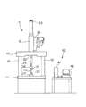
この発明の実施の形態を図面に基づいて説明する。図1は、この発明に係る衝撃試験機の概要図である。図2は、この発明に係る衝撃試験機の主要な制御系を説明するブロック図である。 Embodiments of the present invention will be described with reference to the drawings. FIG. 1 is a schematic view of an impact tester according to the present invention. FIG. 2 is a block diagram illustrating a main control system of the impact tester according to the present invention.
この衝撃試験機は、試験片TPに急速に衝撃を与える衝撃試験を実行するものであり、試験機本体10と、制御装置40を備える。試験機本体10は、テーブル11と、テーブル11に立設された一対の支柱12と、一対の支柱12に架け渡されたクロスヨーク13と、クロスヨーク13に固定された油圧シリンダ31を備える。
This impact tester executes an impact test in which a test piece TP is rapidly impacted, and includes a tester
油圧シリンダ31は、サーボバルブ34を介してテーブル内に配置された油圧源(図示せず)から供給される作動油によって動作する。油圧シリンダ31のピストンロッド32には、助走治具25およびジョイント26を介して上つかみ具21が接続されている。一方で、テーブル11には、力検出器であるロードセル27を介して、下つかみ具22が接続されている。このように、この試験機本体10の構成は、助走治具25により引張方向に助走区間を設け、ピストンロッド32を0.1〜20m/秒の高速で引き上げることにより、試験片TPの両端部を把持する一対のつかみ具を急激に離間させる引張衝撃試験を実行するための構成となっている。引張衝撃試験を実行したときの負荷機構の変位(ストローク)、すなわち、ピストンロッド32の移動量は、ストロークセンサ33により検出され、その時の試験力はロードセル27により検出される。
The
制御装置40は、試験機本体10の動作を制御するための本体制御装置41と、パーソナルコンピュータ42とから構成される。本体制御装置41は、プログラムを格納するメモリ43と、各種演算を実行するMPU(micro processing unit)などの演算装置45と、パーソナルコンピュータ42との通信を行う通信部46とを備える。メモリ43、演算装置45および通信部46は、相互にバス61により接続されている。また、本体制御装置41は、機能的構成として試験制御部44を備える。試験制御部44は、試験制御プログラムとしてメモリ43に格納されている。引張衝撃試験を実行するときには、試験制御プログラムを実行することにより、サーボバルブ34に制御信号が供給され、油圧シリンダ31が動作する。ストロークセンサ33の出力信号と、ロードセル27の出力信号とは所定時間間隔で本体制御装置41に取り込まれる。
The
パーソナルコンピュータ42は、データ解析プログラムを記憶するROM、プロクラム実行時にプログラムをロードして一時的にデータを記憶するRAMなどから成るメモリ51、各種演算を実行するCPU(central processing unit)などの演算装置55、本体制御装置41などの外部接続機器との通信を行う通信部56、データを記憶する記憶装置57、表示装置58および入力装置59を備える。なお、記憶装置57は、衝撃試験の試験力の時系列データなどを記憶する記憶部であり、HDD(hard disk drive)などの大容量記憶装置から構成される。メモリ51、演算装置55、通信部56、記憶装置57、表示装置58および入力装置59は相互にバス71により接続されている。
The
また、パーソナルコンピュータ42は、機能的構成として、後述する固有振動の解析において、試験力の時系列データから試験機の固有振動数を求めるためのデータ区間を抽出するデータ抽出部52と、抽出されたデータ区間に対して周波数スペクトル解析を実行する解析部53と、試験機の固有振動波形を試験力データから除去する振動波形除去部54を備える。データ抽出部52、解析部53、振動波形除去部54は、それぞれデータ抽出プログラム、解析プログラム、振動波形除去プログラムとしてメモリ51に格納されている。これらのプログラムは、演算装置55の作用により実行される。
Further, as a functional configuration, the
引張衝撃試験を実行したときにロードセル27が検出した試験力は、本体制御装置41のメモリ43に入力された後、通信部46からパーソナルコンピュータ42に送信される。パーソナルコンピュータ42の通信部56が受信した試験力は、時系列データとして記憶装置57に記憶される。
The test force detected by the
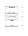
図3は、固有振動の測定手順を示すフローチャートである。このフローチャートでは、PP(ポリプロピレン)、PC(ポリカーボネート)、PS(ポリスチレン)などの合成樹脂片を試験片TPとした引張衝撃試験での固有振動の測定手順を示している。 FIG. 3 is a flowchart showing a measurement procedure of natural vibration. This flowchart shows the procedure for measuring the natural vibration in a tensile impact test using a synthetic resin piece such as PP (polypropylene), PC (polycarbonate), PS (polystyrene) as a test piece TP.
試験機本体10に引張衝撃試験用の治具である上つかみ具21と下つかみ具22が取り付けられ、下つかみ具がロードセル27に緩みなく固定されていることが確認されている状態で、まず、試験条件を設定する(ステップS11)。ユーザは、パーソナルコンピュータ42の入力装置59を用いて試験速度などの試験条件を設定する。そして、試験片TPの両端部を上つかみ具21と下つかみ具22に把持させる(ステップS12)。
First, the upper gripping
次に、データ収集条件を設定する(ステップS13)。ユーザは、パーソナルコンピュータ42の入力装置59を用いて、データ収集開始時刻−終了時刻、サンプリング周波数、取得データ点数(サンプリング点数)などのデータ収集条件を設定する。試験中に試験機本体10に生じた固有振動は、試験片TPを介してロードセル27にかかっていた負荷が破断により除かれたときに顕著となる振動を観測することにより取得可能である。また、試験負荷を与えない状態で、試験治具(この実施形態では下つかみ具22)の重さを受けている状態の試験力も知る必要がある。したがって、データ収集開始時刻−終了時刻の設定においては、試験片TPに引張負荷が加えられる前からデータを取得し、かつ、後述するスペクトル解析に供するに十分なデータ点数(例えば、試験片TPが破断した後のデータ点数が1000点以上となるデータ点数)が得られるように、設定することが好ましい。サンプリング周波数およびサンプリング点数の設定においては、下記式(1)を利用して、周波数分解能が500Hz以下となる値を設定することが好ましい。
Next, the data collection conditions are set (step S13). The user sets data collection conditions such as data collection start time-end time, sampling frequency, and number of acquired data points (sampling points) using the
Δf=1/T=Fs/N ・・・ (1)
なお、式(1)において、Δfは周波数分解能、Tは時間窓長、Fsはサンプリング周波数、Nはサンプリング点数である。
Δf = 1 / T = Fs / N ... (1)
In the equation (1), Δf is the frequency resolution, T is the time window length, Fs is the sampling frequency, and N is the number of sampling points.
データ収集条件の設定が終わると、試験を実行する(ステップS14)。データ収集条件で設定したデータ収集開始時刻から終了時刻までの間にロードセル27が検出した試験力は、本体制御装置41を介してパーソナルコンピュータ42に送られ記憶装置57に保存され、測定は終了する(ステップS15)。
After setting the data collection conditions, the test is executed (step S14). The test force detected by the
図4は、試験力の時系列データの一例を示すグラフである。図5は、図4のグラフにおける試験片TPの破断前後の波形を拡大して示すグラフである。これらのグラフにおいて、縦軸は試験力(kN:キロニュートン)であり、横軸は、時間(μs:マイクロ秒)である。 FIG. 4 is a graph showing an example of time-series data of test force. FIG. 5 is an enlarged graph showing the waveform before and after the fracture of the test piece TP in the graph of FIG. In these graphs, the vertical axis is the test force (kN: kilonewton) and the horizontal axis is the time (μs: microseconds).
試験実行により得られた試験力の時系列データに対して、後述するスペクトル解析に供するに十分なデータ点数があるか否かについては、式(1)を用いて確認することができる。図4のグラフに示す試験力の時系列データでは、図5に拡大して示すように、破断により15000マイクロ秒付近で試験力波形の振幅が大きくなる。破断後のデータの起点は、例えば、図5に示すように、振動波形が1周期半した時刻T1とすることができる。なお、後述するスペクトル解析に供するに十分なデータ点数が取得できなかった場合には、試験片TPを交換し(ステップS12)、データ収集条件の設定を変更し(ステップS13)、再度試験を実行する(ステップ14)。 Whether or not the time-series data of the test force obtained by executing the test has a sufficient number of data points for spectrum analysis described later can be confirmed by using the equation (1). In the time-series data of the test force shown in the graph of FIG. 4, as shown enlarged in FIG. 5, the amplitude of the test force waveform becomes large at around 15,000 microseconds due to the breakage. As shown in FIG. 5, the starting point of the data after the breakage can be, for example, the time T1 in which the vibration waveform is one and a half cycles. If a sufficient number of data points cannot be obtained for spectrum analysis described later, the test piece TP is replaced (step S12), the data collection condition setting is changed (step S13), and the test is executed again. (Step 14).
図6は、固有振動数の解析手順を示すフローチャートである。図7は、試験力の時系列データの一例を示すグラフである。図8は、試験片TPが破断した後の時系列データを示すグラフである。図7、図8のグラフにおいて、縦軸は試験力(kN:キロニュートン)であり、横軸は、時間(μs:マイクロ秒)である。 FIG. 6 is a flowchart showing a procedure for analyzing the natural frequency. FIG. 7 is a graph showing an example of time-series data of test force. FIG. 8 is a graph showing time series data after the test piece TP is broken. In the graphs of FIGS. 7 and 8, the vertical axis represents the test force (kN: kilonewton) and the horizontal axis represents the time (μs: microseconds).
固有振動の解析では、まず、図3に示した測定手順に従って取得した試験力の時系列データを記憶装置57から読み出し、試験片TPから試験力が除かれる前後で時系列データを分離する(ステップS21)。図7に示すグラフは、試験速度5m/sの条件で引張衝撃試験を実行し、サンプリング周波数1000kHzで取得した試験力データである。引張衝撃試験においては、時系列データを試験片TPの破断前と破断後に分離する。この試験力の時系列データの分離においては、図5を参照して説明したように、時刻T1を定め、時刻T1の前後でデータを分離する。そして、図7に破線で示すように時刻T1(2440マイクロ秒)以降のデータを、試験機の固有振動数を求めるためのデータ区間として抽出する(ステップS22:データ抽出工程)。しかる後、ステップS22において抽出した図8に示す試験片TPが破断した後の時系列データに対して、FFT(Fast Fourier Transform:高速フーリエ変換)による周波数スペクトル解析を実行する(ステップS23:解析工程)。
In the analysis of natural vibration, first, the time-series data of the test force acquired according to the measurement procedure shown in FIG. 3 is read from the
図9は、図8に示す時系列データの周波数スペクトル解析結果を示すグラフである。このグラフにおいて、横軸は周波数(Hz:ヘルツ)であり、縦軸は周波数分解能Δf毎のパワーを示す。 FIG. 9 is a graph showing the frequency spectrum analysis result of the time series data shown in FIG. In this graph, the horizontal axis represents frequency (Hz: Hertz), and the vertical axis represents power for each frequency resolution Δf.
周波数スペクトル解析の結果は、表示装置58に表示されるとともに、記憶装置57に記憶される。図9に示すパワースペクトルでは、最もピークが大きい周波数13.8kHを固有振動数とする(ステップS24)。
The result of the frequency spectrum analysis is displayed on the
図10は、時系列データから固有振動数を除去する手順を示すフローチャートである。図11は、試験片TPの破断前の時系列データを示すグラフであり、図12は、図11の時系列データから固有振動数を除去したデータを示すグラフである。これらのグラフにおいて、縦軸は試験力(kN:キロニュートン)であり、横軸は、時間(μs:マイクロ秒)である。 FIG. 10 is a flowchart showing a procedure for removing the natural frequency from the time series data. FIG. 11 is a graph showing time-series data before breaking of the test piece TP, and FIG. 12 is a graph showing data obtained by removing the natural frequency from the time-series data of FIG. In these graphs, the vertical axis is the test force (kN: kilonewton) and the horizontal axis is the time (μs: microseconds).
試験機本体10の固有振動数がわかれば、試験実行により取得した時系列データから、固有振動数を用いて固有振動を除去することにより、引張衝撃試験中の正確な試験力を知ることができる。まず、固有振動波形を除去するデータ範囲を選択し(ステップS31)、移動平均処理を用いて、データに重畳していると考えられる試験機の固有振動を時系列データから除去する(ステップS32:振動波形除去工程)。
If the natural frequency of the testing machine
この実施形態では、図11に示すように、固有振動数の解析手順において、図7の時系列データを試験片TPの破断前後で分離したデータのうち、試験片TPに引張負荷がかかっている状態の時間データを含んでいる試験片TPの破断前の時系列データを、固有振動数を除去対象データとして記憶装置57から呼び出している。なお、一見して、試験機の固有振動がデータ上に重畳していないように見える場合でも、分離前の全時系列データに対して試験機本体10の固有振動を除去したい場合は、データ分離前の時系列データを選択すればよい。
In this embodiment, as shown in FIG. 11, in the natural frequency analysis procedure, the test piece TP is subjected to a tensile load among the data obtained by separating the time series data of FIG. 7 before and after the breakage of the test piece TP. The time-series data before breaking of the test piece TP including the time data of the state is called from the
ステップS32では、先に説明したステップS24で決まった固有振動数と、データ取得時のサンプリング周波数とを使用した下記式(2)により、移動平均処理に使用するデータ点数を定める。 In step S32, the number of data points used for the moving average processing is determined by the following equation (2) using the natural frequency determined in step S24 described above and the sampling frequency at the time of data acquisition.
データ点数=サンプリング周波数/固有振動数 ・・・ (2) Number of data points = sampling frequency / natural frequency ... (2)
この図11のデータは、試験速度5m/sの条件で引張衝撃試験を実行し、サンプリング周波数1000kHzで取得されたものである。したがって、サンプリング周波数1000kHzをステップS24で得た固有振動数13.8kHzで除することにより得られた72.4の整数部分がデータ点数となる。なお、この例のように、サンプリング周波数を固有振動数整数で除した値が整数とならない場合は、小数点以下を切り捨てまたは四捨五入するなどして、整数値とする。 The data in FIG. 11 was obtained by performing a tensile impact test under the condition of a test speed of 5 m / s and at a sampling frequency of 1000 kHz. Therefore, the integer portion of 72.4 obtained by dividing the sampling frequency of 1000 kHz by the natural frequency of 13.8 kHz obtained in step S24 is the data score. If the value obtained by dividing the sampling frequency by the natural frequency integer does not become an integer as in this example, the value after the decimal point is rounded off or rounded off to obtain an integer value.
移動平均処理は、平均化させたいデータを中心に前後同数(点数が前後で1違う場合も含む)のデータを用いて平均化する。図11のデータでは、式(2)を用いた計算で、移動平均処理に使用するデータ点数を72点と定めたことから、平均化させたいデータ(36点目)を中心とした前35点、後ろ36点として平均化処理を実行する。処理対象として選択した時系列データについて移動平均処理が終了すると、固有振動の除去が終了する(ステップS33)。移動平均処理後のデータは、処理前と処理後のデータを比較可能な態様で、表示装置58に表示される。
In the moving average processing, the data to be averaged is averaged using the same number of data before and after (including the case where the score is different by 1 before and after). In the data of FIG. 11, since the number of data points used for the moving average processing was set to 72 points in the calculation using the equation (2), the front 35 points centered on the data to be averaged (36th point). , The averaging process is executed with 36 points behind. When the moving average processing for the time-series data selected as the processing target is completed, the removal of the natural vibration is completed (step S33). The data after the moving average processing is displayed on the
図12に示す移動平均処理により固有振動波形を除去したデータと、図11に示す移動平均処理前のデータを比較すると、図12のデータの方がより滑らかな挙動を示しており、引張負荷が試験片TPに与えられている状態でも、試験機の固有振動が、ロードセル27の測定値に影響を及ぼしていることが理解される。図12に示す例では、図9を参照して説明した周波数スペクトル解析において、最大ピークである13.8kHzを固有振動数と定めて移動平均処理を実行したが、いくつかのピークを固有振動数の候補として、それらの候補について、移動平均処理を実行してもよい。
Comparing the data obtained by removing the natural vibration waveform by the moving average processing shown in FIG. 12 and the data before the moving average processing shown in FIG. 11, the data shown in FIG. 12 shows smoother behavior and the tensile load is higher. It is understood that the natural vibration of the testing machine affects the measured value of the
このように、この発明においては、衝撃試験の評価に試験機の固有振動数を考慮した評価方法を採用していることから、試験機の固有振動によるノイズが取り除かれた波形を得ることにより、正確な試験力値を知ることが可能となる。また、この発明においては、固有振動波形の除去前と除去後のデータを同じ時間軸で見ることができることから、ユーザは、個々の衝撃試験において、試験力データにおける試験機の固有振動の影響を確認することができる。 As described above, in the present invention, since the evaluation method in consideration of the natural frequency of the testing machine is adopted for the evaluation of the impact test, the waveform from which the noise due to the natural vibration of the testing machine is removed can be obtained. It is possible to know the accurate test force value. Further, in the present invention, since the data before and after the removal of the natural vibration waveform can be viewed on the same time axis, the user can see the influence of the natural vibration of the tester on the test force data in each impact test. You can check.
なお、上述した実施形態では、引張衝撃試験について説明したが、ポンチを試験片に衝突させる打ち抜き試験や、3点曲げ試験のように、支点で支持した試験片にポンチを打ち下ろす衝撃試験においても、この発明を適用することができる。 In the above-described embodiment, the tensile impact test has been described, but it is also possible to perform an impact test in which the punch is dropped onto a test piece supported by a fulcrum, such as a punching test in which the punch collides with a test piece and a three-point bending test. , The present invention can be applied.
10 試験機本体
11 テーブル
12 支柱
13 クロスヨーク
21 上つかみ具
22 下つかみ具
25 助走治具
26 ジョイント
27 ロードセル
31 油圧シリンダ
32 ピストンロッド
33 ストロークセンサ
34 サーボバルブ
40 制御装置
41 本体制御装置
42 パーソナルコンピュータ
43 メモリ
44 試験制御部
45 演算装置
46 通信部
51 メモリ
52 データ抽出部
53 解析部
54 振動波形除去部
55 演算装置
56 通信部
57 記憶装置
58 表示装置
59 入力装置
TP 試験片
10
Claims (4)
サンプリング周波数を含むデータ収集条件をユーザが設定するデータ収集条件設定工程と、
衝撃試験の実行により力検出器が前記データ収集条件で取得した時系列データから、試験機の固有振動数を求めるためのデータ区間として、前記試験片が破断した後のデータを抽出するデータ抽出工程と、
前記データ抽出工程において抽出したデータに対して周波数スペクトル解析を実行することにより前記固有振動数を求める解析工程と、
前記固有振動数と前記サンプリング周波数とを用いて、前記時系列データから試験機の固有振動を除去する振動波形除去工程と、
を含む衝撃試験の評価方法。 It is an evaluation method of an impact test that gives a rapid impact to a test piece.
The data collection condition setting process in which the user sets the data collection conditions including the sampling frequency, and
Data extraction step to extract data after the test piece breaks as a data section for obtaining the natural frequency of the testing machine from the time series data acquired by the force detector under the data collection conditions by executing the impact test. When,
An analysis step of obtaining the natural frequency by executing frequency spectrum analysis on the data extracted in the data extraction step, and
Using said sampling frequency before and SL-specific frequency, the vibration waveform removal step of removing the natural frequency of the tester from the time-series data,
Impact test evaluation method including.
前記振動波形除去工程は、前記サンプリング周波数を前記周波数スペクトルから定めた前記固有振動数で除することにより定めたデータ点数での移動平均処理を前記力検出器が検出した時系列データに対して実行する衝撃試験の評価方法。 In the impact test evaluation method according to claim 1,
The vibration waveform removal step, executes a moving average process in the defined data points by dividing the sampling frequency by the natural frequency determined from the frequency spectrum with respect to the time series data detected by the force detector How to evaluate the impact test.
前記振動波形除去工程は、前記周波数スペクトルの最も大きいピークとなる周波数を前記固有振動数とし、前記サンプリング周波数を前記固有振動数で除することにより定めたデータ点数での移動平均処理を前記力検出器が検出した時系列データに対して実行する衝撃試験の評価方法。 In the impact test evaluation method according to claim 1,
The vibration waveform removal step, the frequency of the largest peak of the frequency spectrum and the natural frequency, said force detecting a moving average process of the sampling frequency data points that defines by dividing the natural frequency An impact test evaluation method performed on the time-series data detected by the instrument.
前記試験片に試験力を与える負荷機構と、
前記試験片に与えられた試験力を検出する力検出器と、
前記力検出器が検出した時系列データを記憶する記憶部を備えた制御装置と、
を備え、
前記制御装置は、
サンプリング周波数を含むデータ収集条件のユーザによる設定を受け付ける入力装置と、
前記記憶部に記憶された、前記データ収集条件で取得した時系列データから、試験機の固有振動数を求めるためのデータ区間として、前記試験片が破断した後のデータを抽出するデータ抽出部と、
前記抽出部において抽出したデータに対して、周波数スペクトル解析を実行することにより前記固有振動数を求める解析部と、
前記固有振動数と前記サンプリング周波数とを用いて、前記時系列データから試験機の固有振動を除去する振動波形除去部と、
を備える衝撃試験機。 It is an impact tester that rapidly impacts the test piece.
A load mechanism that gives test force to the test piece,
A force detector that detects the test force applied to the test piece, and
A control device provided with a storage unit that stores time-series data detected by the force detector, and
With
The control device is
An input device that accepts user settings for data collection conditions, including sampling frequency,
A data extraction unit that extracts data after the test piece is broken as a data section for obtaining the natural frequency of the testing machine from the time series data stored in the storage unit and acquired under the data collection conditions. ,
An analysis unit that obtains the natural frequency by executing frequency spectrum analysis on the data extracted by the extraction unit.
Before SL using unique frequency and said sampling frequency, the vibration waveform removal unit for removing the natural frequency of the tester from the time-series data,
Impact tester equipped with.
Priority Applications (4)
| Application Number | Priority Date | Filing Date | Title |
|---|---|---|---|
| JP2017118517A JP6930240B2 (en) | 2017-06-16 | 2017-06-16 | Impact test evaluation method and impact tester |
| EP18177809.3A EP3415894A1 (en) | 2017-06-16 | 2018-06-14 | Evaluation method of impact test and impact tester |
| US16/009,220 US20180364139A1 (en) | 2017-06-16 | 2018-06-15 | Evaluation method of impact test and impact tester |
| CN201810617873.5A CN109142100A (en) | 2017-06-16 | 2018-06-15 | The appraisal procedure and shock machine of impact test |
Applications Claiming Priority (1)
| Application Number | Priority Date | Filing Date | Title |
|---|---|---|---|
| JP2017118517A JP6930240B2 (en) | 2017-06-16 | 2017-06-16 | Impact test evaluation method and impact tester |
Publications (3)
| Publication Number | Publication Date |
|---|---|
| JP2019002828A JP2019002828A (en) | 2019-01-10 |
| JP2019002828A5 JP2019002828A5 (en) | 2020-05-28 |
| JP6930240B2 true JP6930240B2 (en) | 2021-09-01 |
Family
ID=62636124
Family Applications (1)
| Application Number | Title | Priority Date | Filing Date |
|---|---|---|---|
| JP2017118517A Active JP6930240B2 (en) | 2017-06-16 | 2017-06-16 | Impact test evaluation method and impact tester |
Country Status (4)
| Country | Link |
|---|---|
| US (1) | US20180364139A1 (en) |
| EP (1) | EP3415894A1 (en) |
| JP (1) | JP6930240B2 (en) |
| CN (1) | CN109142100A (en) |
Families Citing this family (3)
| Publication number | Priority date | Publication date | Assignee | Title |
|---|---|---|---|---|
| JP6866830B2 (en) * | 2017-11-22 | 2021-04-28 | 株式会社島津製作所 | Material tester and gripping force detection method |
| JP7135932B2 (en) * | 2019-02-26 | 2022-09-13 | 株式会社島津製作所 | TENSILE TESTER AND CONTROL METHOD FOR TENSILE TESTER |
| CN115046831B (en) * | 2022-07-20 | 2023-08-29 | 赛迈科先进材料股份有限公司 | Method for testing axial fatigue of graphite |
Family Cites Families (21)
| Publication number | Priority date | Publication date | Assignee | Title |
|---|---|---|---|---|
| GB118175A (en) * | 1917-09-22 | 1918-08-22 | Avery Ltd W & T | Improvements in Impact Testing Machines. |
| JPS5819979B2 (en) * | 1978-08-01 | 1983-04-21 | 日章電機株式会社 | Load measurement method and device for dynamic testing of materials |
| JPH0765954B2 (en) * | 1986-10-30 | 1995-07-19 | ジャパンセンサー株式会社 | Dynamic characteristic measuring device using instrumented Charpy tester |
| CA1323683C (en) * | 1988-09-30 | 1993-10-26 | Michel J. Pettigrew | Loose rock detector |
| JPH03211457A (en) * | 1990-01-16 | 1991-09-17 | Toyota Motor Corp | Crack detecting method |
| JP2941150B2 (en) * | 1993-07-27 | 1999-08-25 | 株式会社奥村組 | Rock property measurement device |
| US5400640A (en) * | 1993-10-29 | 1995-03-28 | International Business Machines Corporation | Pyrotechnic shock machine |
| EP1070961A1 (en) * | 1999-07-19 | 2001-01-24 | BRITISH TELECOMMUNICATIONS public limited company | Test apparatus |
| JP2002333437A (en) * | 2001-05-10 | 2002-11-22 | Mitsubishi Heavy Ind Ltd | Impact inspection device |
| JP2004333143A (en) | 2003-04-30 | 2004-11-25 | Shimadzu Corp | Impact tester, and installation structure thereof |
| JP4062163B2 (en) * | 2003-05-02 | 2008-03-19 | 株式会社島津製作所 | Spanner for impact tensile testing machine |
| JP4033119B2 (en) * | 2003-12-10 | 2008-01-16 | 株式会社島津製作所 | Material testing method, material testing machine |
| US20080295602A1 (en) * | 2007-06-01 | 2008-12-04 | Gavin Wallace | Method and System for Sorting Green Lumber |
| EP2120034A1 (en) * | 2008-05-16 | 2009-11-18 | Vrije Universiteit Brussel | Method and apparatus for providing an optimal test panel for the non-destructive measurement of elastic properties of structural materials |
| JP5824858B2 (en) * | 2010-05-10 | 2015-12-02 | Jfeスチール株式会社 | Method and apparatus for imaging structure of welded portion |
| JP2012017998A (en) * | 2010-07-06 | 2012-01-26 | Shin Etsu Chem Co Ltd | Polycrystalline silicon rod, inspection method of polycrystalline silicon rod, and manufacturing method of polycrystalline silicon rod |
| JP5527696B2 (en) * | 2010-09-27 | 2014-06-18 | 地方独立行政法人大阪府立産業技術総合研究所 | Impact strength evaluation apparatus, method and program |
| KR101212646B1 (en) * | 2011-05-09 | 2012-12-14 | 세종대학교산학협력단 | Impact test system using energy frame |
| US9851332B2 (en) * | 2014-09-19 | 2017-12-26 | King Fahd University Of Petroleum And Minerals | Process for determining weld quality using flexural characteristics |
| JP6578195B2 (en) * | 2015-11-26 | 2019-09-18 | Dmg森精機株式会社 | Method for deriving natural frequency of cutting tool, method for creating stability limit curve, and device for deriving natural frequency of cutting tool |
| JP6794936B2 (en) * | 2017-06-16 | 2020-12-02 | 株式会社島津製作所 | Impact test evaluation method and impact tester |
-
2017
- 2017-06-16 JP JP2017118517A patent/JP6930240B2/en active Active
-
2018
- 2018-06-14 EP EP18177809.3A patent/EP3415894A1/en not_active Withdrawn
- 2018-06-15 US US16/009,220 patent/US20180364139A1/en not_active Abandoned
- 2018-06-15 CN CN201810617873.5A patent/CN109142100A/en not_active Withdrawn
Also Published As
| Publication number | Publication date |
|---|---|
| CN109142100A (en) | 2019-01-04 |
| EP3415894A1 (en) | 2018-12-19 |
| JP2019002828A (en) | 2019-01-10 |
| US20180364139A1 (en) | 2018-12-20 |
Similar Documents
| Publication | Publication Date | Title |
|---|---|---|
| JP6794936B2 (en) | Impact test evaluation method and impact tester | |
| JP6930240B2 (en) | Impact test evaluation method and impact tester | |
| EP3521801B1 (en) | Test result evaluating method and a kit comprising a material tester and a hammer | |
| JP6911783B2 (en) | Test result evaluation method and material testing machine | |
| KR101179134B1 (en) | System for Measuring High Velocity Impact Acoustic Emissions and the Method Therefor | |
| CN108627388B (en) | Method for measuring instantaneous impact force | |
| CN105571763A (en) | Bolt pretightening force detection method and device | |
| JP2019002828A5 (en) | ||
| JP5996569B2 (en) | Soundness inspection device for concrete structure, hammer for soundness inspection and soundness inspection method | |
| CN104913988A (en) | Hopkinson principle-based concrete axial tensile strength measuring method | |
| JP5714930B2 (en) | Quality diagnosis method for concrete structures | |
| JP6653072B2 (en) | Method for evaluating the number of impacts of hydraulic hammer, method for exploring front ground using the same, and system for exploring front ground | |
| CN108020688B (en) | From spectrum Fourier transformation High-g accelerometer resonant frequency extracting method at times | |
| CN111919101A (en) | Impact testing device and method for operating an impact testing device | |
| Wirtz et al. | Experimental results of frequency-based classification of damages in composites | |
| JP6481500B2 (en) | Method for evaluating number of hammer hits, exploration method for front ground using the hammer, and exploration system for front ground | |
| Yoo et al. | Application of Model-based Design Approach on Dynamic Tensile Testing of Carbon/Epoxy Composites at Intermediate Strain Rates | |
| JP6315381B2 (en) | Elastic wave input device and defect search method for concrete structure using the elastic wave input device | |
| JP2021181967A (en) | Non-destructive inspection equipment | |
| RU1778675C (en) | Device for determining strength of concrete | |
| NEDELCU et al. | The estimation of dynamic properties of a fixed beam using experimental modal testing | |
| CN107878969A (en) | Intelligent Recognition dustbin and its recognition methods | |
| Chavan et al. | EXPERIMENTAL MEASUREMENT OF DYNAMIC SIFs THROUGH IMPACT BENDING TESTS | |
| UA75797C2 (en) | Method for determining the modulus of elasticity and the viscosity factor of the ground at three-dimensional deformation | |
| PL224036B1 (en) | Method for testing the mechanical properties of materials in the form of samples undergoing simultaneous influence torsional moment and axial force |
Legal Events
| Date | Code | Title | Description |
|---|---|---|---|
| RD02 | Notification of acceptance of power of attorney |
Free format text: JAPANESE INTERMEDIATE CODE: A7422 Effective date: 20200220 |
|
| A521 | Request for written amendment filed |
Free format text: JAPANESE INTERMEDIATE CODE: A523 Effective date: 20200402 |
|
| A621 | Written request for application examination |
Free format text: JAPANESE INTERMEDIATE CODE: A621 Effective date: 20200402 |
|
| A977 | Report on retrieval |
Free format text: JAPANESE INTERMEDIATE CODE: A971007 Effective date: 20210325 |
|
| A131 | Notification of reasons for refusal |
Free format text: JAPANESE INTERMEDIATE CODE: A131 Effective date: 20210406 |
|
| A521 | Request for written amendment filed |
Free format text: JAPANESE INTERMEDIATE CODE: A523 Effective date: 20210602 |
|
| TRDD | Decision of grant or rejection written | ||
| A01 | Written decision to grant a patent or to grant a registration (utility model) |
Free format text: JAPANESE INTERMEDIATE CODE: A01 Effective date: 20210713 |
|
| A61 | First payment of annual fees (during grant procedure) |
Free format text: JAPANESE INTERMEDIATE CODE: A61 Effective date: 20210726 |
|
| R151 | Written notification of patent or utility model registration |
Ref document number: 6930240 Country of ref document: JP Free format text: JAPANESE INTERMEDIATE CODE: R151 |