JP6866830B2 - Material tester and gripping force detection method - Google Patents
Material tester and gripping force detection method Download PDFInfo
- Publication number
- JP6866830B2 JP6866830B2 JP2017224874A JP2017224874A JP6866830B2 JP 6866830 B2 JP6866830 B2 JP 6866830B2 JP 2017224874 A JP2017224874 A JP 2017224874A JP 2017224874 A JP2017224874 A JP 2017224874A JP 6866830 B2 JP6866830 B2 JP 6866830B2
- Authority
- JP
- Japan
- Prior art keywords
- natural frequency
- test
- test piece
- force
- gripping
- Prior art date
- Legal status (The legal status is an assumption and is not a legal conclusion. Google has not performed a legal analysis and makes no representation as to the accuracy of the status listed.)
- Active
Links
Images


Classifications
-
- G—PHYSICS
- G01—MEASURING; TESTING
- G01N—INVESTIGATING OR ANALYSING MATERIALS BY DETERMINING THEIR CHEMICAL OR PHYSICAL PROPERTIES
- G01N3/00—Investigating strength properties of solid materials by application of mechanical stress
- G01N3/02—Details
- G01N3/04—Chucks
-
- G—PHYSICS
- G01—MEASURING; TESTING
- G01N—INVESTIGATING OR ANALYSING MATERIALS BY DETERMINING THEIR CHEMICAL OR PHYSICAL PROPERTIES
- G01N3/00—Investigating strength properties of solid materials by application of mechanical stress
- G01N3/08—Investigating strength properties of solid materials by application of mechanical stress by applying steady tensile or compressive forces
-
- G—PHYSICS
- G01—MEASURING; TESTING
- G01H—MEASUREMENT OF MECHANICAL VIBRATIONS OR ULTRASONIC, SONIC OR INFRASONIC WAVES
- G01H13/00—Measuring resonant frequency
-
- G—PHYSICS
- G01—MEASURING; TESTING
- G01N—INVESTIGATING OR ANALYSING MATERIALS BY DETERMINING THEIR CHEMICAL OR PHYSICAL PROPERTIES
- G01N29/00—Investigating or analysing materials by the use of ultrasonic, sonic or infrasonic waves; Visualisation of the interior of objects by transmitting ultrasonic or sonic waves through the object
- G01N29/04—Analysing solids
- G01N29/12—Analysing solids by measuring frequency or resonance of acoustic waves
-
- G—PHYSICS
- G01—MEASURING; TESTING
- G01N—INVESTIGATING OR ANALYSING MATERIALS BY DETERMINING THEIR CHEMICAL OR PHYSICAL PROPERTIES
- G01N29/00—Investigating or analysing materials by the use of ultrasonic, sonic or infrasonic waves; Visualisation of the interior of objects by transmitting ultrasonic or sonic waves through the object
- G01N29/44—Processing the detected response signal, e.g. electronic circuits specially adapted therefor
- G01N29/4409—Processing the detected response signal, e.g. electronic circuits specially adapted therefor by comparison
- G01N29/4427—Processing the detected response signal, e.g. electronic circuits specially adapted therefor by comparison with stored values, e.g. threshold values
-
- G—PHYSICS
- G01—MEASURING; TESTING
- G01N—INVESTIGATING OR ANALYSING MATERIALS BY DETERMINING THEIR CHEMICAL OR PHYSICAL PROPERTIES
- G01N3/00—Investigating strength properties of solid materials by application of mechanical stress
- G01N3/02—Details
- G01N3/06—Special adaptations of indicating or recording means
- G01N3/066—Special adaptations of indicating or recording means with electrical indicating or recording means
-
- G—PHYSICS
- G01—MEASURING; TESTING
- G01N—INVESTIGATING OR ANALYSING MATERIALS BY DETERMINING THEIR CHEMICAL OR PHYSICAL PROPERTIES
- G01N3/00—Investigating strength properties of solid materials by application of mechanical stress
- G01N3/30—Investigating strength properties of solid materials by application of mechanical stress by applying a single impulsive force, e.g. by falling weight
-
- G—PHYSICS
- G01—MEASURING; TESTING
- G01N—INVESTIGATING OR ANALYSING MATERIALS BY DETERMINING THEIR CHEMICAL OR PHYSICAL PROPERTIES
- G01N3/00—Investigating strength properties of solid materials by application of mechanical stress
- G01N3/62—Manufacturing, calibrating, or repairing devices used in investigations covered by the preceding subgroups
-
- G—PHYSICS
- G01—MEASURING; TESTING
- G01N—INVESTIGATING OR ANALYSING MATERIALS BY DETERMINING THEIR CHEMICAL OR PHYSICAL PROPERTIES
- G01N2203/00—Investigating strength properties of solid materials by application of mechanical stress
- G01N2203/02—Details not specific for a particular testing method
- G01N2203/04—Chucks, fixtures, jaws, holders or anvils
- G01N2203/0482—Chucks, fixtures, jaws, holders or anvils comprising sensing means
-
- G—PHYSICS
- G01—MEASURING; TESTING
- G01N—INVESTIGATING OR ANALYSING MATERIALS BY DETERMINING THEIR CHEMICAL OR PHYSICAL PROPERTIES
- G01N2203/00—Investigating strength properties of solid materials by application of mechanical stress
- G01N2203/02—Details not specific for a particular testing method
- G01N2203/06—Indicating or recording means; Sensing means
- G01N2203/067—Parameter measured for estimating the property
- G01N2203/0688—Time or frequency
-
- G—PHYSICS
- G01—MEASURING; TESTING
- G01N—INVESTIGATING OR ANALYSING MATERIALS BY DETERMINING THEIR CHEMICAL OR PHYSICAL PROPERTIES
- G01N3/00—Investigating strength properties of solid materials by application of mechanical stress
- G01N3/22—Investigating strength properties of solid materials by application of mechanical stress by applying steady torsional forces
Description
この発明は、試験片の両端を一対のつかみ具により把持した状態で前記試験片に引張試験力を付与することにより引張試験を行う材料試験機およびこの材料試験機における把持力検出方法に関する。 The present invention relates to a material tester that performs a tensile test by applying a tensile test force to the test piece in a state where both ends of the test piece are gripped by a pair of grippers, and a gripping force detection method in the material tester.
このような材料試験機に使用されるつかみ具は、例えば、ナットを回転させることにより試験片を挟持する一対のつかみ歯を移動させ、試験片をつかみ具に固定させる構成となっている。このような構成を有するつかみ具においては、つかみ具による試験片の把持力は、ナットを回転させる時のトルクの大きさと比例する(特許文献1参照)。 The gripping tool used in such a material testing machine has a configuration in which, for example, a nut is rotated to move a pair of gripping teeth that sandwich the test piece, and the test piece is fixed to the gripping tool. In a gripper having such a configuration, the gripping force of the test piece by the gripper is proportional to the magnitude of the torque when rotating the nut (see Patent Document 1).
このような材料試験機においては、試験片をつかみ具によって適正な把持力で把持した状態で材料試験を実行しないと、正確な試験結果を得ることができない。しかしながら、試験片が適正な把持力で把持されているか否かを確認することは困難であり、材料試験を完了した後に、その試験結果を確認したり、試験片における把持領域の表面を目視で確認することしか試験片が適正に把持されていたか否かを確認することはできなかった。 In such a material testing machine, accurate test results cannot be obtained unless the material test is performed in a state where the test piece is gripped by a gripping tool with an appropriate gripping force. However, it is difficult to confirm whether or not the test piece is gripped with an appropriate gripping force, and after completing the material test, the test result can be confirmed or the surface of the gripping area on the test piece can be visually confirmed. Only by confirming, it was possible to confirm whether or not the test piece was properly gripped.
また、試験片をつかみ具によって把持するときに、トルクレンチ等を使用して把持力を測定することも不可能ではないが、その作業は極めて煩雑であり、また、作業者によってバラツキを生ずるという問題がある。 Further, when gripping the test piece with a gripper, it is not impossible to measure the gripping force using a torque wrench or the like, but the work is extremely complicated and varies depending on the operator. There's a problem.
この発明は上記課題を解決するためになされたものであり、簡単な構成でありながら、つかみ具により試験片が適正な把持力で把持されているか否かを容易に判断することが可能な材料試験機および把持力検出方法を提供することを目的とする。 The present invention has been made to solve the above problems, and is a material capable of easily determining whether or not a test piece is gripped by an appropriate gripping force with a gripping tool, although it has a simple structure. It is an object of the present invention to provide a testing machine and a method for detecting a gripping force.
請求項1に記載の発明は、試験片の両端を一対のつかみ具により把持した状態で前記試験片に引張試験力を付与することにより引張試験を行う材料試験機において、前記一対のつかみ具のうちの一方のつかみ具により前記試験片を適正な把持力で把持したときの、前記試験片と前記一方のつかみ具とを含む系の固有振動数を、適正固有振動数として記憶する記憶部と、引張試験開始前に前記一方のつかみ具により前記試験片を把持したときの、前記試験片と前記一方のつかみ具とを含む系の固有振動数を、試験開始前固有振動数として測定する試験開始前固有振動数測定手段と、前記試験開始前固有振動数と前記適正固有振動数とを比較する比較部と、を備えたことを特徴とする。 The invention according to claim 1 is a material testing machine for performing a tensile test by applying a tensile test force to the test piece in a state where both ends of the test piece are gripped by a pair of grippers. A storage unit that stores the natural frequency of the system including the test piece and the one gripping tool when the test piece is gripped with an appropriate gripping force by one of the gripping tools as an appropriate natural frequency. , A test in which the natural frequency of the system including the test piece and the one gripping tool when the test piece is gripped by the one gripping tool before the start of the tensile test is measured as the natural frequency before the start of the test. It is characterized by including a pre-start natural frequency measuring means and a comparison unit for comparing the pre-start natural frequency and the appropriate natural frequency.
請求項2に記載の発明は、試験片の両端を一対のつかみ具により把持した状態で前記試験片に引張試験力を付与するとともに、前記一対のつかみ具のうちの一方のつかみ具に接続された力検出器で引張試験力を測定することにより引張試験を行う材料試験機において、前記力検出器に接続されたつかみ具を打撃したときの前記力検出器による力の検出値に基づいて、前記試験片と前記力検出器に接続されたつかみ具とを含む系の固有振動数を演算する演算部と、前記力検出器に接続されたつかみ具により前記試験片を適正な把持力で把持した状態において前記力検出器に接続されたつかみ具を打撃したときの、前記演算部により演算した前記試験片と前記力検出器に接続されたつかみ具とを含む系の固有振動数を、適正固有振動数として記憶する記憶部と、引張試験開始前に前記力検出器に接続されたつかみ具により前記試験片を把持した状態において前記力検出器に接続されたつかみ具を打撃したときの、前記演算部により演算した前記試験片と前記力検出器に接続されたつかみ具とを含む系の固有振動数を、試験開始前固有振動数とし、当該試験開始前固有振動数を前記記憶部に記憶した適正固有振動数と比較する比較部と、を備えたことを特徴とする。 The invention according to claim 2 applies a tensile test force to the test piece in a state where both ends of the test piece are gripped by a pair of grippers, and is connected to one of the pair of grippers. In a material tester that performs a tensile test by measuring a tensile test force with a force detector, based on the force detection value by the force detector when hitting a gripper connected to the force detector. The test piece is gripped with an appropriate gripping force by a calculation unit that calculates the natural frequency of the system including the test piece and the gripping tool connected to the force detector, and the gripping tool connected to the force detector. When the gripping tool connected to the force detector is hit in this state, the natural frequency of the system including the test piece calculated by the calculation unit and the gripping tool connected to the force detector is appropriately set. When the gripper connected to the force detector is hit while the test piece is gripped by the storage unit stored as the natural frequency and the gripper connected to the force detector before the start of the tensile test. The natural frequency of the system including the test piece calculated by the calculation unit and the gripping tool connected to the force detector is defined as the natural frequency before the start of the test, and the natural frequency before the start of the test is stored in the storage unit. It is characterized by being provided with a comparison unit for comparison with a memorized appropriate natural frequency.
請求項3に記載の発明は、請求項1または請求項2に記載の材料試験機において、前記試験開始前固有振動数が前記適正固有振動数以上のときに材料試験の開始を許容するとともに、前記試験開始前固有振動数が前記適正固有振動数より小さいときに警告表示を行う制御部を備える。 The invention according to claim 3 allows the material testing machine according to claim 1 or 2 to start a material test when the natural frequency before the start of the test is equal to or higher than the appropriate natural frequency. A control unit that displays a warning when the natural frequency before the start of the test is smaller than the appropriate natural frequency is provided.
請求項4に記載の発明は、試験片の両端を一対のつかみ具により把持した状態で前記試験片に引張試験力を付与することにより引張試験を行う材料試験機において、前記試験片が前記つかみ具に適正な把持力で把持されているか否かを検出する把持力検出方法であって、前記一対のつかみ具のうちの一方のつかみ具により前記試験片を適正な把持力で把持したときの前記試験片と前記一方のつかみ具とを含む系の固有振動数を、適正固有振動数として記憶する適正固有振動数記憶工程と、引張試験開始前に前記一方のつかみ具により前記試験片を把持したときの、前記試験片と前記一方のつかみ具とを含む系の固有振動数を、試験開始前固有振動数として測定する試験開始前固有振動数測定工程と、前記試験開始前固有振動数と前記適正固有振動数とを比較する比較工程と、を含むことを特徴とする。 The invention according to claim 4 is a material testing machine for performing a tensile test by applying a tensile test force to the test piece in a state where both ends of the test piece are gripped by a pair of gripping tools, wherein the test piece grips the test piece. A gripping force detecting method for detecting whether or not a tool is gripped with an appropriate gripping force, when the test piece is gripped with an appropriate gripping force by one of the pair of gripping tools. An appropriate natural frequency storage step of storing the natural frequency of the system including the test piece and the one gripping tool as an appropriate natural frequency, and gripping the test piece with the one gripper before starting the tensile test. The natural frequency before the start of the test, which measures the natural frequency of the system including the test piece and the one gripping tool as the natural frequency before the start of the test, and the natural frequency before the start of the test. It is characterized by including a comparison step of comparing with the appropriate natural frequency.
請求項5に記載の発明は、試験片の両端を一対のつかみ具により把持した状態で前記試験片に引張試験力を付与するとともに、前記一対のつかみ具のうちの一方のつかみ具に接続された力検出器で引張試験力を測定することにより引張試験を行う材料試験機において、前記試験片が前記つかみ具に適正な把持力で把持されているか否かを検出する把持力検出方法であって、前記力検出器に接続されたつかみ具により前記試験片を適正な把持力で把持した状態において前記力検出器に接続されたつかみ具を打撃したときの、前記力検出器による力の検出値を測定する第1測定工程と、前記第1測定工程において測定された前記力検出器による力の検出値に基づいて、前記試験片と前記力検出器に接続されたつかみ具とを含む系の固有振動数を適正固有振動数として演算する適正固有振動数演算工程と、引張試験開始前に前記力検出器に接続されたつかみ具により前記試験片を把持した状態において前記力検出器に接続されたつかみ具を打撃したときの、前記力検出器による力の検出値を測定する第2測定工程と、前記第2測定工程において測定された前記力検出器による力の検出値に基づいて、前記試験片と前記力検出器に接続されたつかみ具とを含む系の固有振動数を試験開始前固有振動数として演算する試験開始前固有振動数演算工程と、前記試験開始前固有振動数と前記適正固有振動数とを比較する比較工程と、を含むことを特徴とする。
The invention according to
請求項1から請求項5に記載の発明によれば、試験片と力検出器に接続されたつかみ具とを含む系の固有振動数に基づいて、つかみ具により試験片が適正な把持力で把持されているか否かを容易に判断することが可能となる。このため、簡易な構成でありながら、試験片を適正に把持させることができ、正確な材料試験を実行することが可能となる。 According to the inventions of claims 1 to 5, the gripping tool allows the test piece to have an appropriate gripping force based on the natural frequency of the system including the test piece and the gripping tool connected to the force detector. It is possible to easily determine whether or not the product is gripped. Therefore, although the structure is simple, the test piece can be properly gripped, and an accurate material test can be performed.
請求項2に記載の発明によれば、本来的の材料試験機に備わっている力検出器の振動データに基づいて把持力が適正か否かを判断するから、追加構成が不要となって簡単に把持力適否の判断を実行できる。 According to the second aspect of the present invention, since it is determined whether or not the gripping force is appropriate based on the vibration data of the force detector provided in the original material testing machine, no additional configuration is required and it is easy. It is possible to judge whether the gripping force is appropriate or not.
請求項3に記載の発明によれば、試験片がつかみ具により適正に把持されたときにのみ試験を実行することができるとともに、つかみ具による把持力が適正でないときにはそれを認識することが可能となる。 According to the third aspect of the present invention, the test can be performed only when the test piece is properly gripped by the gripping tool, and it is possible to recognize when the gripping force by the gripping tool is not appropriate. It becomes.
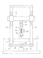
以下、この発明の実施の形態を図面に基づいて説明する。図1は、この発明に係る材料試験機の概要図である。 Hereinafter, embodiments of the present invention will be described with reference to the drawings. FIG. 1 is a schematic view of a material testing machine according to the present invention.
この材料試験機は、試験片10に対して引張試験を実行するためのものであり、基台11と、この基台11上に立設された左右一対のねじ棹12と、左右一対のねじ棹12と螺合するナット部を備え、ねじ棹12に対して昇降するクロスヘッド15とを備える。クロスヘッド15には、上つかみ具21が、軸心調整機構13および力検出器であるロードセル14を介して配設されている。また、基台11には下つかみ具22が固定されている。試験片10は、その両端をこれらの上つかみ具21および下つかみ具22により把持される。
This material testing machine is for performing a tensile test on the
一対のねじ棹12の下端部には、各々、同期ベルト16と係合する同期プーリー17が配設されている。また、この同期ベルト16は、モータ19の駆動により回転する同期プーリー18とも係合している。このため、一対のねじ棹12は、モータ19の駆動により同期して回転する。そして、一対のねじ棹12が同期して回転することにより、クロスヘッド15は、一対のねじ棹12の軸心方向に昇降する。
At the lower ends of the pair of
試験片10に負荷される試験力は、ロードセル14により検出される。また、試験片10の上下の標点間の変位量は、接触方式または非接触方式の変位計23により検出される。ロードセル14および変位計23からの信号は後述する制御部40に入力される。制御部40は、ロードセル14および変位計23からの信号に基づいて、モータ19の駆動制御信号を作成する。これにより、モータ19の回転が制御され、試験片10に対する引張試験が実行される。
The test force applied to the
図2は、上つかみ具21付近の拡大図である。
FIG. 2 is an enlarged view of the vicinity of the
この上つかみ具21は、試験片10を両側から挟むように把持するための一対のつかみ歯28を備える。この一対のつかみ歯28による試験片10の把持力は、上つかみ具21におけるハンドル29を回転させることにより調整される。このような構成は、材料試験機においてマニュアル操作により試験片を把持するつかみ具として一般的な構成であり、例えば、上述した特許文献1にも同様のつかみ具の構成が記載されている。
The upper
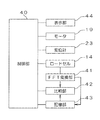
図3は、この発明に係る材料試験機の主要な制御系を示すブロック図である。 FIG. 3 is a block diagram showing a main control system of the material testing machine according to the present invention.
この発明に係る材料試験機は、プロセッサーを有し装置全体を制御する制御部40を備える。この制御部40は、上述したモータ19、変位計23およびロードセル14と接続されている。また、この制御部40は、各種のデータの表示および後述する警告表示を行うためのLCDタッチパネル等から構成される表示部44と接続されている。
The material testing machine according to the present invention includes a
また、制御部40は、ロードセル14による力の検出値に基づいて、試験片10とロードセル14に接続された上つかみ具21とを含む系の固有振動数を演算するためのこの発明に係る演算部としてのFFT変換部41と、ロードセル14を介して接続されている。
また、制御部40は、FFT変換部41により演算した固有振動数を記憶するための記憶部43と接続されている。さらに、制御部40は、試験開始前にFFT変換部41により演算した固有振動数と記憶部43に記憶した固有振動数とを比較する比較部42とも接続されている。なお、上記のFFT変換部41、比較部42、および、記憶部43は制御部40内の構成として制御部40に含まれていてもよい。
Further, the
Further, the
次に、以上のような構成を有する材料試験機により材料試験を開始するときの動作について説明する。図4および図5は、この発明に係る材料試験機により引張試験を開始するときの動作を示すフローチャートである。ここで、図4は、試験片10を上つかみ具21により適正な把持力で把持したときの試験片10とロードセル14に接続された上つかみ具21とを含む系の固有振動数を測定する適正固有振動数測定工程を示し、図5は、試験片10が上つかみ具21により適正な把持力で把持されているか否かを確認するための試験開始前固有振動数測定工程を示している。
Next, the operation when the material test is started by the material testing machine having the above configuration will be described. 4 and 5 are flowcharts showing an operation when a tensile test is started by the material testing machine according to the present invention. Here, FIG. 4 measures the natural frequency of the system including the
適正固有振動数測定工程においては、上つかみ具21により試験片10を適正な把持力で把持したときの試験片10とロードセル14に接続された上つかみ具21とを含む系の固有振動数を適正固有振動数として測定する。これは、試験片10が大きな把持力で把持されたときには、試験片10とロードセル14に接続された上つかみ具21とを含む系の固有振動数も大きくなることが見出されたことによるものである。
In the proper natural frequency measurement step, the natural frequency of the system including the
図6は、ある試験片に対する把持力と、その試験片やつかみ具等を含む系の固有振動数との関係を示すグラフである。 FIG. 6 is a graph showing the relationship between the gripping force on a certain test piece and the natural frequency of the system including the test piece, the gripping tool, and the like.
このグラフに示すように、試験片に対する把持力が大きくなれば、試験片やつかみ具等を含む系の固有振動数も大きくなる。このグラフに示す条件の場合においては、材料試験を適正に実行するのに必要な試験力が、例えば、20(N・m)であるとすれば、試験片やつかみ具等を含む系の固有振動数が16kHz以上となればよいことになる。 As shown in this graph, as the gripping force with respect to the test piece increases, the natural frequency of the system including the test piece, the gripper, and the like also increases. In the case of the conditions shown in this graph, if the test force required to properly execute the material test is, for example, 20 (Nm), the uniqueness of the system including the test piece, the gripper, etc. It suffices if the frequency becomes 16 kHz or more.
再度図4を参照して、適正固有振動数測定工程においては、最初に、試験片10を上つかみ具21に装着する(ステップS11)。そして、図2に示す上つかみ具21におけるハンドル29を回転させ、試験片10を一対のつかみ歯28により適正な把持力となる状態で挟持する。このときの試験片10の把持力の測定は、引張試験の開始時に一度だけ実行すればよいことから、トルクレンチ等を使用して測定してもよく、実際に試験片10に引張試験力を付与することにより測定してもよい。
With reference to FIG. 4 again, in the proper natural frequency measurement step, the
試験片10を適正な把持力で把持した後(ステップS12)、上つかみ具21を打撃する(ステップS13)。このときには、図2において矢印で示すように、上つかみ具21の下端部を、ハンマー等により、引張試験時の試験片10への試験力の付与方向と同一方向に向けて打撃することで振動を与える。
After gripping the
そして、打撃後のロードセル14による力の測定値を測定し、この測定値をFFT変換部41に入力する。FFT変換部41においては、ロードセル14による力の測定値をFFT(Fast Fourier Transform)変換する。そして、FFT変換後の波形のピークから、試験片10とロードセル14に接続された上つかみ具21とを含む系の固有振動数を演算する(ステップS14)。ここで、FFT変換は、高速フーリエ変換とも呼称され、離散フーリエ変換を計算機上で高速に計算するためのアルゴリズムである。
Then, the measured value of the force by the
演算された試験片10とロードセル14に接続された上つかみ具21とを含む系の固有振動数は、適正固有振動数として、記憶部43に記憶される(ステップS15)。
The natural frequency of the system including the calculated
以上の準備工程が終了すれば、試験片10に対する引張試験を開始する。このときには、実際に試験を開始する前に、試験片10が上つかみ具21により適正な把持力で把持されているか否かを確認するための、図5に示す試験開始前固有振動数測定工程を実行する。
When the above preparatory steps are completed, a tensile test on the
試験開始前固有振動数測定工程においては、まず、次に試験を行うべき試験片10を上つかみ具21に装着する(ステップS21)。そして、上つかみ具21を打撃する(ステップS22)。このときには、上述した適正固有振動数測定工程と同様、図2において矢印で示すように、上つかみ具21の下端部を、ハンマー等により、引張試験時の試験片10への試験力の付与方向と同一方向に向けて打撃する。
In the natural frequency measurement step before the start of the test, first, the
そして、打撃後のロードセル14による力の測定値を測定し、この測定値をFFT変換部41に入力する。FFT変換部41においては、ロードセル14による力の測定値をFFT変換することにより、試験片10とロードセル14に接続された上つかみ具21とを含む系の固有振動数を演算する(ステップS23)。
Then, the measured value of the force by the
演算された試験片10とロードセル14に接続された上つかみ具21とを含む系の固有振動数は、試験開始前固有振動数として、記憶部43に記憶された適正固有振動数と比較される(ステップS24)。そして、測定された試験開始前固有振動数が記憶された適正固有振動数以上である場合には(ステップS25)、制御部40が引張試験の開始を許可する(ステップS26)。この場合においては、上端が上つかみ具21に把持されている試験片10の下端を下つかみ具22により把持した上で、この試験片10に対する引張試験が実行される。
The natural frequency of the system including the calculated
ここで、図6に示すように、試験片10に対する把持力が大きくなれば、試験片10や上つかみ具21等を含む系の固有振動数も大きくなる。従って、測定された試験開始前固有振動数が記憶された適正固有振動数以上である場合には、試験片10に対する把持力が適正な把持力の下限以上であると判断することができる。なお、試験片10に対する把持力の上限は、試験片10が損傷する限界等に基づいて決定すればよい。
Here, as shown in FIG. 6, as the gripping force with respect to the
一方、測定された試験開始前固有振動数が記憶された適正固有振動数より小さい場合においては(ステップS25)、制御部40が引張試験の開始を許可せず、表示部44に対して警告表示が成される(ステップS27)。これにより、試験片10の上端が適正に把持されていない状態において引張試験が開始されることを未然に防止することができる。なお、表示部44に対する警告表示とともに、あるいは、表示部44に対する警告表示に変えて、警告音により把持力が適正でないことを表示するようにしてもよい。
On the other hand, when the measured natural frequency before the start of the test is smaller than the stored appropriate natural frequency (step S25), the
上述した実施形態においては、ロードセル14による力の測定値から固有振動数を求めるようにしている。その場合は通常の材料試験機に追加する構成が不要なので、手軽に固有振動数を求めることができる。場合によっては、ロードセル14から得られる振動データを利用する代わりに加速度センサなどを上つかみ具21に取り付けておき、それから得られる振動データから固有振動数を求めてもよい。
In the above-described embodiment, the natural frequency is obtained from the measured value of the force by the
また、上述した実施形態においては、適正固有振動数測定工程を実行した後、試験開始前固有振動数測定工程を実行している。しかしながら、適正固有振動数測定工程を実施するかわりに、試験片と上つかみ具の組み合わせ毎に、図6に示すグラフと同様、上つかみ具による把持力と試験片やつかみ具等を含む系の固有振動数との関係を求め、適正な把持力となる固有振動数を記憶しておいてもよい。この場合には、試験片と上つかみ具の組む合わせから、適正な把持力となる適正固有振動数を読み出して、これを試験開始前固有振動数と比較すればよい。 Further, in the above-described embodiment, after executing the appropriate natural frequency measurement step, the natural frequency measurement step before the start of the test is executed. However, instead of carrying out the proper natural frequency measurement step, for each combination of the test piece and the upper gripper, as in the graph shown in FIG. 6, the gripping force of the upper gripper and the system including the test piece, the gripper, etc. The relationship with the natural frequency may be obtained, and the natural frequency that provides an appropriate gripping force may be stored. In this case, the proper natural frequency that provides the proper gripping force may be read out from the combination of the test piece and the upper gripper, and this may be compared with the natural frequency before the start of the test.
また、上述した実施形態においては、一対のねじ棹によりクロスヘッドを昇降させる形式の材料試験機にこの発明を適用しているが、その他の形式の材料試験機にこの発明を適用してもよい。 Further, in the above-described embodiment, the present invention is applied to a material testing machine of a type in which the crosshead is moved up and down by a pair of screw paddles, but the present invention may be applied to other types of material testing machines. ..
10 試験片
11 基台
12 ねじ棹
13 軸心調整機構
14 ロードセル
15 クロスヘッド
21 上つかみ具
22 下つかみ具
23 変位計
28 つかみ歯
29 ハンドル
40 制御部
41 FFT変換部
42 比較部
43 記憶部
44 表示部
10
Claims (5)
前記一対のつかみ具のうちの一方のつかみ具により前記試験片を適正な把持力で把持したときの、前記試験片と前記一方のつかみ具とを含む系の固有振動数を、適正固有振動数として記憶する記憶部と、
引張試験開始前に前記一方のつかみ具により前記試験片を把持したときの、前記試験片と前記一方のつかみ具とを含む系の固有振動数を、試験開始前固有振動数として測定する試験開始前固有振動数測定手段と、
前記試験開始前固有振動数と前記適正固有振動数とを比較する比較部と、
を備えたことを特徴とする材料試験機。 In a material testing machine that performs a tensile test by applying a tensile test force to the test piece while both ends of the test piece are gripped by a pair of grippers.
When the test piece is gripped with an appropriate gripping force by one of the pair of gripping tools, the natural frequency of the system including the test piece and the one gripping tool is set to the appropriate natural frequency. A storage unit that memorizes as
The test start in which the natural frequency of the system including the test piece and the one grip when the test piece is gripped by the one grip before the start of the tensile test is measured as the natural frequency before the start of the test. Pre-natural frequency measuring means and
A comparison unit that compares the natural frequency before the start of the test with the appropriate natural frequency,
A material testing machine characterized by being equipped with.
前記力検出器に接続されたつかみ具を打撃したときの前記力検出器による力の検出値に基づいて、前記試験片と前記力検出器に接続されたつかみ具とを含む系の固有振動数を演算する演算部と、
前記力検出器に接続されたつかみ具により前記試験片を適正な把持力で把持した状態において前記力検出器に接続されたつかみ具を打撃したときの、前記演算部により演算した前記試験片と前記力検出器に接続されたつかみ具とを含む系の固有振動数を、適正固有振動数として記憶する記憶部と、
引張試験開始前に前記力検出器に接続されたつかみ具により前記試験片を把持した状態において前記力検出器に接続されたつかみ具を打撃したときの、前記演算部により演算した前記試験片と前記力検出器に接続されたつかみ具とを含む系の固有振動数を、試験開始前固有振動数とし、当該試験開始前固有振動数を前記記憶部に記憶した適正固有振動数と比較する比較部と、
を備えたことを特徴とする材料試験機。 A tensile test force is applied to the test piece while both ends of the test piece are gripped by a pair of grippers, and a tensile test force is applied by a force detector connected to one of the pair of grippers. In a material testing machine that performs a tensile test by measuring
The natural frequency of the system including the test piece and the gripper connected to the force detector based on the force detected value by the force detector when the gripper connected to the force detector is hit. And the arithmetic unit that calculates
With the test piece calculated by the calculation unit when the gripping tool connected to the force detector is hit while the test piece is gripped with an appropriate gripping force by the gripping tool connected to the force detector. A storage unit that stores the natural frequency of the system including the gripping tool connected to the force detector as an appropriate natural frequency, and
With the test piece calculated by the calculation unit when the grip tool connected to the force detector is hit while the test piece is gripped by the grip tool connected to the force detector before the start of the tensile test. The natural frequency of the system including the gripper connected to the force detector is defined as the natural frequency before the start of the test, and the natural frequency before the start of the test is compared with the appropriate natural frequency stored in the storage unit. Department and
A material testing machine characterized by being equipped with.
前記試験開始前固有振動数が前記適正固有振動数以上のときに材料試験の開始を許容するとともに、前記試験開始前固有振動数が前記適正固有振動数より小さいときに警告表示を行う制御部を備える材料試験機。 In the material testing machine according to claim 1 or 2.
A control unit that allows the start of the material test when the natural frequency before the start of the test is equal to or higher than the proper natural frequency and displays a warning when the natural frequency before the start of the test is smaller than the proper natural frequency. Material testing machine equipped.
前記一対のつかみ具のうちの一方のつかみ具により前記試験片を適正な把持力で把持したときの前記試験片と前記一方のつかみ具とを含む系の固有振動数を、適正固有振動数として記憶する適正固有振動数記憶工程と、
引張試験開始前に前記一方のつかみ具により前記試験片を把持したときの、前記試験片と前記一方のつかみ具とを含む系の固有振動数を、試験開始前固有振動数として測定する試験開始前固有振動数測定工程と、
前記試験開始前固有振動数と前記適正固有振動数とを比較する比較工程と、
を含むことを特徴とする把持力検出方法。 In a material testing machine that performs a tensile test by applying a tensile test force to the test piece while both ends of the test piece are gripped by a pair of gripping tools, the test piece is gripped by the gripping tool with an appropriate gripping force. It is a gripping force detection method that detects whether or not it is
The natural frequency of the system including the test piece and the one grip when the test piece is gripped with an appropriate gripping force by one of the pair of grips is defined as the proper natural frequency. Appropriate natural frequency storage process to be stored and
The test start in which the natural frequency of the system including the test piece and the one grip when the test piece is gripped by the one grip before the start of the tensile test is measured as the natural frequency before the start of the test. Pre-natural frequency measurement process and
A comparison step of comparing the natural frequency before the start of the test with the appropriate natural frequency, and
A method for detecting a gripping force, which comprises.
前記力検出器に接続されたつかみ具により前記試験片を適正な把持力で把持した状態において前記力検出器に接続されたつかみ具を打撃したときの、前記力検出器による力の検出値を測定する第1測定工程と、
前記第1測定工程において測定された前記力検出器による力の検出値に基づいて、前記試験片と前記力検出器に接続されたつかみ具とを含む系の固有振動数を適正固有振動数として演算する適正固有振動数演算工程と、
引張試験開始前に前記力検出器に接続されたつかみ具により前記試験片を把持した状態において前記力検出器に接続されたつかみ具を打撃したときの、前記力検出器による力の検出値を測定する第2測定工程と、
前記第2測定工程において測定された前記力検出器による力の検出値に基づいて、前記試験片と前記力検出器に接続されたつかみ具とを含む系の固有振動数を試験開始前固有振動数として演算する試験開始前固有振動数演算工程と、
前記試験開始前固有振動数と前記適正固有振動数とを比較する比較工程と、
を含むことを特徴とする把持力検出方法。 A tensile test force is applied to the test piece while both ends of the test piece are gripped by a pair of grippers, and a tensile test force is applied by a force detector connected to one of the pair of grippers. A gripping force detecting method for detecting whether or not the test piece is gripped by the gripping tool with an appropriate gripping force in a material testing machine that performs a tensile test by measuring.
The value detected by the force detector when the gripping tool connected to the force detector is hit while the test piece is gripped with an appropriate gripping force by the gripping tool connected to the force detector. The first measurement process to be measured and
Based on the force detection value by the force detector measured in the first measurement step, the natural frequency of the system including the test piece and the gripper connected to the force detector is set as the appropriate natural frequency. Appropriate natural frequency calculation process to calculate and
The value detected by the force detector when the gripper connected to the force detector is hit while the test piece is gripped by the gripper connected to the force detector before the start of the tensile test. The second measurement process to measure and
Based on the force detection value by the force detector measured in the second measurement step, the natural frequency of the system including the test piece and the gripper connected to the force detector is determined as the natural vibration before the start of the test. The natural frequency calculation process before the start of the test, which is calculated as a number,
A comparison step of comparing the natural frequency before the start of the test with the appropriate natural frequency, and
A method for detecting a gripping force, which comprises.
Priority Applications (4)
| Application Number | Priority Date | Filing Date | Title |
|---|---|---|---|
| JP2017224874A JP6866830B2 (en) | 2017-11-22 | 2017-11-22 | Material tester and gripping force detection method |
| CN201811094250.0A CN109813597B (en) | 2017-11-22 | 2018-09-19 | Material testing machine and holding force detection method |
| EP18196746.4A EP3489652B1 (en) | 2017-11-22 | 2018-09-26 | Material testing machine and gripping force detecting method |
| US16/166,185 US10928281B2 (en) | 2017-11-22 | 2018-10-22 | Material testing machine and gripping force detecting method |
Applications Claiming Priority (1)
| Application Number | Priority Date | Filing Date | Title |
|---|---|---|---|
| JP2017224874A JP6866830B2 (en) | 2017-11-22 | 2017-11-22 | Material tester and gripping force detection method |
Publications (3)
| Publication Number | Publication Date |
|---|---|
| JP2019095296A JP2019095296A (en) | 2019-06-20 |
| JP2019095296A5 JP2019095296A5 (en) | 2020-04-30 |
| JP6866830B2 true JP6866830B2 (en) | 2021-04-28 |
Family
ID=63685637
Family Applications (1)
| Application Number | Title | Priority Date | Filing Date |
|---|---|---|---|
| JP2017224874A Active JP6866830B2 (en) | 2017-11-22 | 2017-11-22 | Material tester and gripping force detection method |
Country Status (4)
| Country | Link |
|---|---|
| US (1) | US10928281B2 (en) |
| EP (1) | EP3489652B1 (en) |
| JP (1) | JP6866830B2 (en) |
| CN (1) | CN109813597B (en) |
Families Citing this family (9)
| Publication number | Priority date | Publication date | Assignee | Title |
|---|---|---|---|---|
| CN109154495B (en) * | 2016-05-24 | 2021-10-29 | 伊利诺斯工具制品有限公司 | Three-dimensional calibration tool and method |
| JP6987689B2 (en) * | 2018-03-30 | 2022-01-05 | 日本発條株式会社 | Load measuring device and method |
| US11035767B1 (en) * | 2019-05-01 | 2021-06-15 | The United States Of Americas As Represented By The Secretary Of The Navy | Apparatus for determining swollen-polymer cross-link density |
| CN114341615A (en) * | 2019-09-13 | 2022-04-12 | 株式会社岛津制作所 | Tensile testing machine and control method for tensile testing machine |
| CN110726637A (en) * | 2019-12-02 | 2020-01-24 | 吉林大学 | Centering adjustment device and adjustment method |
| US11624741B2 (en) | 2020-06-09 | 2023-04-11 | Fraunhofer-Gesellschaft zur Förderung der angewandten Forschung e.V. | Sensor arrangement and method for sensing an amount or a concentration of a target fluid in a medium with the sensor arrangement |
| CN112720304A (en) * | 2020-12-28 | 2021-04-30 | 崔光锦 | Clamping device for tensile strength test of new material |
| CN112799300B (en) * | 2020-12-30 | 2022-04-22 | 湘潭大学 | Indentation instrument load control method and system based on fuzzy predictive control |
| CN113804537B (en) * | 2021-08-05 | 2022-08-16 | 北京航空航天大学 | Clamp capable of applying pull/press cyclic load to CT test piece |
Family Cites Families (58)
| Publication number | Priority date | Publication date | Assignee | Title |
|---|---|---|---|---|
| US3306100A (en) * | 1964-02-25 | 1967-02-28 | Skidmore Wilhelm Mfg Co | Ultrasonic bolt tension tester |
| US3777557A (en) * | 1971-11-05 | 1973-12-11 | Greenwood Mills Corp | Strand tester |
| US3751977A (en) * | 1972-04-19 | 1973-08-14 | Chem Instr Corp | Material analyzing apparatus |
| US4096741A (en) * | 1976-08-23 | 1978-06-27 | Sternstein Sanford S | Materials testing device |
| CH644450A5 (en) * | 1980-02-11 | 1984-07-31 | Russenberger Pruefmasch | DEVICE FOR THE VIBRATION STRENGTH TEST. |
| US4426875A (en) * | 1981-12-14 | 1984-01-24 | Rca Corporation | Strain measurement |
| JPS60244839A (en) * | 1984-05-19 | 1985-12-04 | Kureha Chem Ind Co Ltd | Material testing instrument |
| DE3712073A1 (en) * | 1987-04-09 | 1988-10-20 | Bayer Ag | METHOD AND DEVICE FOR MEASURING THE LIABILITY OF FIBERS IN FIBER REINFORCED PLASTICS |
| DE3720303C2 (en) * | 1987-06-19 | 1993-09-30 | Schenck Ag Carl | Sample clamping device for testing machines |
| US4864865A (en) * | 1988-11-04 | 1989-09-12 | The United States Of America As Represented By The Administrator Of The National Aeronautics And Space Administration | Tensile film clamps and mounting block for the rheovibron and autovibron viscoelastometer |
| JPH0754288B2 (en) * | 1991-03-29 | 1995-06-07 | 株式会社島津製作所 | Material testing machine with telescopic screw rod |
| US5242512A (en) * | 1992-03-13 | 1993-09-07 | Alloying Surfaces, Inc. | Method and apparatus for relieving residual stresses |
| US5269181A (en) * | 1992-05-20 | 1993-12-14 | Gibson Ronald F | Apparatus and process for measuring mechanical properties of fibers |
| US5533399A (en) * | 1992-09-30 | 1996-07-09 | Wayne State University | Method and apparatus for non-destructive measurement of elastic properties of structural materials |
| CH689127A5 (en) * | 1994-02-10 | 1998-10-15 | Zellweger Uster Ag | Method for measuring the tearing strength of fibers. |
| DE4412724A1 (en) * | 1994-04-13 | 1995-10-26 | Erich Gerards | Detecting cracks during dynamic material testing |
| US5694807A (en) * | 1994-09-29 | 1997-12-09 | The United States Of America As Represented By The Administrator Of The National Aeronautics And Space Administration | Apparatus and method for determining the mass density of a filament |
| US5554807A (en) * | 1995-04-06 | 1996-09-10 | Tranquilla; Michael N. | Belt damping |
| DE29519501U1 (en) * | 1995-12-08 | 1996-01-25 | Stein Herbert Textechno | Device for testing single fibers |
| US5798456A (en) * | 1996-11-19 | 1998-08-25 | Unisys Corp. | Predicting behavior of synchronous flexible webs |
| ATE213830T1 (en) * | 1997-09-02 | 2002-03-15 | Chemiefaser Lenzing Ag | METHOD FOR DETERMINING THE STRENGTH PROPERTIES OF LONG STRETCHED TEXTILE TEST SPECIMEN AND DEVICE FOR IMPLEMENTING THE METHOD |
| JPH11108901A (en) * | 1997-10-03 | 1999-04-23 | Ishikawajima Harima Heavy Ind Co Ltd | Method and apparatus for measuring young's modulus of clad material by impulsive sound |
| JP3939886B2 (en) * | 1999-12-24 | 2007-07-04 | 株式会社日平トヤマ | Grinder |
| US6778914B1 (en) * | 2000-03-17 | 2004-08-17 | University Of Delaware | Dynamic interphase-loading apparatus and method of using the same |
| EP1219515B1 (en) * | 2000-06-23 | 2011-01-19 | Kabushiki Kaisha Bridgestone | Method for estimating vehicular running state, vehicular running state estimating device, vehicle control device, and tire wheel |
| JP2002139411A (en) * | 2000-10-31 | 2002-05-17 | Shimadzu Corp | Tension tester |
| US6665483B2 (en) * | 2001-03-13 | 2003-12-16 | 3M Innovative Properties Company | Apparatus and method for filament tensioning |
| US6403322B1 (en) * | 2001-03-27 | 2002-06-11 | Lam Research Corporation | Acoustic detection of dechucking and apparatus therefor |
| JP2003121323A (en) * | 2001-10-16 | 2003-04-23 | Shimadzu Corp | High speed tensile tester |
| US6698288B2 (en) * | 2001-12-06 | 2004-03-02 | General Electric Company | Method and system for assembling and nondestructive testing of assemblies with composite components |
| DE10214756B4 (en) * | 2002-04-03 | 2011-06-16 | Mettler-Toledo Ag | Method and device for carrying out dynamic-mechanical analyzes |
| EP1695063A1 (en) * | 2003-12-11 | 2006-08-30 | Eidgenössische Technische Hochschule Zürich | Device and method for measuring flexural damping of fibres |
| JP4390070B2 (en) * | 2005-01-26 | 2009-12-24 | 株式会社島津製作所 | Material testing machine |
| US7143642B1 (en) * | 2005-07-01 | 2006-12-05 | Uster Technologies, Inc. | Integrated moisture, length, and strength tester |
| CN1793827A (en) * | 2005-12-16 | 2006-06-28 | 北京工业大学 | Microstructure resonance single direction bending pulling multiaxle fatigue experimental device |
| EP2120034A1 (en) * | 2008-05-16 | 2009-11-18 | Vrije Universiteit Brussel | Method and apparatus for providing an optimal test panel for the non-destructive measurement of elastic properties of structural materials |
| GB0900747D0 (en) * | 2009-01-16 | 2009-03-04 | Isis Innovation | Mechanical oscillator |
| US8276464B2 (en) * | 2010-01-11 | 2012-10-02 | Mahle International Gmbh | Transverse load apparatus |
| US8863583B2 (en) * | 2010-05-06 | 2014-10-21 | Shimadzu Corporation | Material testing system |
| CN101832881B (en) * | 2010-05-14 | 2012-03-28 | 华中科技大学 | Method for detecting dynamic characteristics of fixing combination portion of machine tool |
| US8863584B2 (en) * | 2010-07-22 | 2014-10-21 | Shimadzu Corporation | Material testing system |
| TW201300756A (en) * | 2011-06-28 | 2013-01-01 | Kun-Ta Lee | Impact generating unit and impact generation assembly comprising the same |
| US8875579B2 (en) * | 2012-03-26 | 2014-11-04 | GM Global Technology Operations LLC | Method and apparatus for non-destructive weld testing |
| JP2014018822A (en) * | 2012-07-17 | 2014-02-03 | Amada Co Ltd | Tool exchange method, and device |
| US9696218B2 (en) * | 2012-08-08 | 2017-07-04 | Mts Systems Corporation | Test specimen holder for high temperature environments |
| JP5998732B2 (en) * | 2012-08-08 | 2016-09-28 | 株式会社島津製作所 | Hardness testing machine |
| JP6004113B2 (en) * | 2013-08-07 | 2016-10-05 | 株式会社島津製作所 | Jig mounting device for material testing machine |
| JP6094463B2 (en) * | 2013-12-09 | 2017-03-15 | 株式会社島津製作所 | Material testing machine |
| EP3123144A4 (en) * | 2014-03-28 | 2017-12-13 | United Technologies Corporation | Material testing apparatus and method |
| JP6172041B2 (en) * | 2014-05-13 | 2017-08-02 | 株式会社島津製作所 | Material testing machine |
| CN104007015B (en) * | 2014-06-18 | 2016-01-27 | 哈尔滨工业大学 | Mechanics Performance Testing device and the method by this device to test micro structures natural frequency |
| CN104849147A (en) * | 2015-05-26 | 2015-08-19 | 山东交通学院 | Modal natural frequency-based metal material Young modulus measurement device and method |
| IL240316B (en) * | 2015-08-03 | 2018-10-31 | Technion Res & Dev Foundation | Method and system for parametric amplification |
| JP6219545B1 (en) * | 2017-03-10 | 2017-10-25 | 住友精密工業株式会社 | Vibration type angular velocity sensor |
| JP6930240B2 (en) * | 2017-06-16 | 2021-09-01 | 株式会社島津製作所 | Impact test evaluation method and impact tester |
| US10809170B2 (en) * | 2017-07-17 | 2020-10-20 | The University Of Akron | Dynamic mechanical analysis (DMA) measurement system with an adjustable clamp assembly |
| JP7010031B2 (en) * | 2018-02-01 | 2022-01-26 | 株式会社島津製作所 | Amplitude detection method and material tester |
| JP6911783B2 (en) * | 2018-02-01 | 2021-07-28 | 株式会社島津製作所 | Test result evaluation method and material testing machine |
-
2017
- 2017-11-22 JP JP2017224874A patent/JP6866830B2/en active Active
-
2018
- 2018-09-19 CN CN201811094250.0A patent/CN109813597B/en active Active
- 2018-09-26 EP EP18196746.4A patent/EP3489652B1/en active Active
- 2018-10-22 US US16/166,185 patent/US10928281B2/en active Active
Also Published As
| Publication number | Publication date |
|---|---|
| CN109813597A (en) | 2019-05-28 |
| US20190154554A1 (en) | 2019-05-23 |
| US10928281B2 (en) | 2021-02-23 |
| EP3489652A1 (en) | 2019-05-29 |
| EP3489652B1 (en) | 2020-12-02 |
| CN109813597B (en) | 2021-08-17 |
| JP2019095296A (en) | 2019-06-20 |
Similar Documents
| Publication | Publication Date | Title |
|---|---|---|
| JP6866830B2 (en) | Material tester and gripping force detection method | |
| JP5645193B2 (en) | Inspection tool and inspection method for fixed fasteners | |
| JP4869490B2 (en) | Torque wrench for retightening inspection | |
| US9366608B2 (en) | Tensile test machine | |
| JP2019095296A5 (en) | ||
| JP6467209B2 (en) | Measuring method of cogging torque of electric motor | |
| JP2019132768A (en) | Amplitude detection method and material tester | |
| JP6911783B2 (en) | Test result evaluation method and material testing machine | |
| JP2012125887A (en) | Torque tester | |
| JP2002318180A (en) | Uniaxial bidirectional tensile tester and sample central part measuring device using it | |
| WO2020110354A1 (en) | Material testing machine and method of controlling material testing machine | |
| JP4394983B2 (en) | Tightening torque measuring instrument tester | |
| JPH10274609A (en) | Method and machine for torsion test | |
| JP5459201B2 (en) | Material testing machine | |
| JP4239752B2 (en) | Material testing machine | |
| JP3835023B2 (en) | Screw tightening axial force measuring method, screw tightening method using the measuring method, and apparatus thereof | |
| JP4390071B2 (en) | Material testing machine | |
| JPH08261858A (en) | Torque transducer measuring apparatus | |
| JP2000193574A (en) | Torsion tester for rotary body | |
| TWI665433B (en) | Water pipe clamp performance test system and test method | |
| JP4206614B2 (en) | Material testing machine | |
| JP6642371B2 (en) | Material testing machine | |
| JPH0261537A (en) | Tester for gold shaft | |
| JP2015087153A (en) | Material testing machine | |
| JP5541220B2 (en) | Material testing machine |
Legal Events
| Date | Code | Title | Description |
|---|---|---|---|
| RD02 | Notification of acceptance of power of attorney |
Free format text: JAPANESE INTERMEDIATE CODE: A7422 Effective date: 20200220 |
|
| A521 | Request for written amendment filed |
Free format text: JAPANESE INTERMEDIATE CODE: A523 Effective date: 20200312 |
|
| A621 | Written request for application examination |
Free format text: JAPANESE INTERMEDIATE CODE: A621 Effective date: 20200312 |
|
| A977 | Report on retrieval |
Free format text: JAPANESE INTERMEDIATE CODE: A971007 Effective date: 20210224 |
|
| TRDD | Decision of grant or rejection written | ||
| A01 | Written decision to grant a patent or to grant a registration (utility model) |
Free format text: JAPANESE INTERMEDIATE CODE: A01 Effective date: 20210309 |
|
| A61 | First payment of annual fees (during grant procedure) |
Free format text: JAPANESE INTERMEDIATE CODE: A61 Effective date: 20210322 |
|
| R151 | Written notification of patent or utility model registration |
Ref document number: 6866830 Country of ref document: JP Free format text: JAPANESE INTERMEDIATE CODE: R151 |