JP6916873B2 - Removal of nitrates from water - Google Patents
Removal of nitrates from water Download PDFInfo
- Publication number
- JP6916873B2 JP6916873B2 JP2019519231A JP2019519231A JP6916873B2 JP 6916873 B2 JP6916873 B2 JP 6916873B2 JP 2019519231 A JP2019519231 A JP 2019519231A JP 2019519231 A JP2019519231 A JP 2019519231A JP 6916873 B2 JP6916873 B2 JP 6916873B2
- Authority
- JP
- Japan
- Prior art keywords
- water
- tank
- denitrification
- tanks
- salt water
- Prior art date
- Legal status (The legal status is an assumption and is not a legal conclusion. Google has not performed a legal analysis and makes no representation as to the accuracy of the status listed.)
- Active
Links
Images


Classifications
-
- C—CHEMISTRY; METALLURGY
- C02—TREATMENT OF WATER, WASTE WATER, SEWAGE, OR SLUDGE
- C02F—TREATMENT OF WATER, WASTE WATER, SEWAGE, OR SLUDGE
- C02F3/00—Biological treatment of water, waste water, or sewage
- C02F3/30—Aerobic and anaerobic processes
- C02F3/302—Nitrification and denitrification treatment
- C02F3/305—Nitrification and denitrification treatment characterised by the denitrification
-
- C—CHEMISTRY; METALLURGY
- C02—TREATMENT OF WATER, WASTE WATER, SEWAGE, OR SLUDGE
- C02F—TREATMENT OF WATER, WASTE WATER, SEWAGE, OR SLUDGE
- C02F1/00—Treatment of water, waste water, or sewage
- C02F1/68—Treatment of water, waste water, or sewage by addition of specified substances, e.g. trace elements, for ameliorating potable water
- C02F1/685—Devices for dosing the additives
-
- C—CHEMISTRY; METALLURGY
- C02—TREATMENT OF WATER, WASTE WATER, SEWAGE, OR SLUDGE
- C02F—TREATMENT OF WATER, WASTE WATER, SEWAGE, OR SLUDGE
- C02F3/00—Biological treatment of water, waste water, or sewage
- C02F3/28—Anaerobic digestion processes
- C02F3/2806—Anaerobic processes using solid supports for microorganisms
-
- C—CHEMISTRY; METALLURGY
- C02—TREATMENT OF WATER, WASTE WATER, SEWAGE, OR SLUDGE
- C02F—TREATMENT OF WATER, WASTE WATER, SEWAGE, OR SLUDGE
- C02F3/00—Biological treatment of water, waste water, or sewage
- C02F3/34—Biological treatment of water, waste water, or sewage characterised by the microorganisms used
- C02F3/345—Biological treatment of water, waste water, or sewage characterised by the microorganisms used for biological oxidation or reduction of sulfur compounds
-
- C—CHEMISTRY; METALLURGY
- C02—TREATMENT OF WATER, WASTE WATER, SEWAGE, OR SLUDGE
- C02F—TREATMENT OF WATER, WASTE WATER, SEWAGE, OR SLUDGE
- C02F9/00—Multistage treatment of water, waste water or sewage
-
- A—HUMAN NECESSITIES
- A01—AGRICULTURE; FORESTRY; ANIMAL HUSBANDRY; HUNTING; TRAPPING; FISHING
- A01K—ANIMAL HUSBANDRY; CARE OF BIRDS, FISHES, INSECTS; FISHING; REARING OR BREEDING ANIMALS, NOT OTHERWISE PROVIDED FOR; NEW BREEDS OF ANIMALS
- A01K63/00—Receptacles for live fish, e.g. aquaria; Terraria
- A01K63/04—Arrangements for treating water specially adapted to receptacles for live fish
- A01K63/045—Filters for aquaria
-
- C—CHEMISTRY; METALLURGY
- C02—TREATMENT OF WATER, WASTE WATER, SEWAGE, OR SLUDGE
- C02F—TREATMENT OF WATER, WASTE WATER, SEWAGE, OR SLUDGE
- C02F1/00—Treatment of water, waste water, or sewage
- C02F1/02—Treatment of water, waste water, or sewage by heating
-
- C—CHEMISTRY; METALLURGY
- C02—TREATMENT OF WATER, WASTE WATER, SEWAGE, OR SLUDGE
- C02F—TREATMENT OF WATER, WASTE WATER, SEWAGE, OR SLUDGE
- C02F1/00—Treatment of water, waste water, or sewage
- C02F1/66—Treatment of water, waste water, or sewage by neutralisation; pH adjustment
-
- C—CHEMISTRY; METALLURGY
- C02—TREATMENT OF WATER, WASTE WATER, SEWAGE, OR SLUDGE
- C02F—TREATMENT OF WATER, WASTE WATER, SEWAGE, OR SLUDGE
- C02F1/00—Treatment of water, waste water, or sewage
- C02F1/72—Treatment of water, waste water, or sewage by oxidation
- C02F1/78—Treatment of water, waste water, or sewage by oxidation with ozone
-
- C—CHEMISTRY; METALLURGY
- C02—TREATMENT OF WATER, WASTE WATER, SEWAGE, OR SLUDGE
- C02F—TREATMENT OF WATER, WASTE WATER, SEWAGE, OR SLUDGE
- C02F2101/00—Nature of the contaminant
- C02F2101/10—Inorganic compounds
- C02F2101/101—Sulfur compounds
-
- C—CHEMISTRY; METALLURGY
- C02—TREATMENT OF WATER, WASTE WATER, SEWAGE, OR SLUDGE
- C02F—TREATMENT OF WATER, WASTE WATER, SEWAGE, OR SLUDGE
- C02F2101/00—Nature of the contaminant
- C02F2101/10—Inorganic compounds
- C02F2101/16—Nitrogen compounds, e.g. ammonia
- C02F2101/163—Nitrates
-
- C—CHEMISTRY; METALLURGY
- C02—TREATMENT OF WATER, WASTE WATER, SEWAGE, OR SLUDGE
- C02F—TREATMENT OF WATER, WASTE WATER, SEWAGE, OR SLUDGE
- C02F2103/00—Nature of the water, waste water, sewage or sludge to be treated
- C02F2103/20—Nature of the water, waste water, sewage or sludge to be treated from animal husbandry
-
- C—CHEMISTRY; METALLURGY
- C02—TREATMENT OF WATER, WASTE WATER, SEWAGE, OR SLUDGE
- C02F—TREATMENT OF WATER, WASTE WATER, SEWAGE, OR SLUDGE
- C02F2103/00—Nature of the water, waste water, sewage or sludge to be treated
- C02F2103/22—Nature of the water, waste water, sewage or sludge to be treated from the processing of animals, e.g. poultry, fish, or parts thereof
-
- C—CHEMISTRY; METALLURGY
- C02—TREATMENT OF WATER, WASTE WATER, SEWAGE, OR SLUDGE
- C02F—TREATMENT OF WATER, WASTE WATER, SEWAGE, OR SLUDGE
- C02F2203/00—Apparatus and plants for the biological treatment of water, waste water or sewage
- C02F2203/006—Apparatus and plants for the biological treatment of water, waste water or sewage details of construction, e.g. specially adapted seals, modules, connections
-
- C—CHEMISTRY; METALLURGY
- C02—TREATMENT OF WATER, WASTE WATER, SEWAGE, OR SLUDGE
- C02F—TREATMENT OF WATER, WASTE WATER, SEWAGE, OR SLUDGE
- C02F2209/00—Controlling or monitoring parameters in water treatment
- C02F2209/005—Processes using a programmable logic controller [PLC]
- C02F2209/006—Processes using a programmable logic controller [PLC] comprising a software program or a logic diagram
-
- C—CHEMISTRY; METALLURGY
- C02—TREATMENT OF WATER, WASTE WATER, SEWAGE, OR SLUDGE
- C02F—TREATMENT OF WATER, WASTE WATER, SEWAGE, OR SLUDGE
- C02F2209/00—Controlling or monitoring parameters in water treatment
- C02F2209/02—Temperature
-
- C—CHEMISTRY; METALLURGY
- C02—TREATMENT OF WATER, WASTE WATER, SEWAGE, OR SLUDGE
- C02F—TREATMENT OF WATER, WASTE WATER, SEWAGE, OR SLUDGE
- C02F2209/00—Controlling or monitoring parameters in water treatment
- C02F2209/04—Oxidation reduction potential [ORP]
-
- C—CHEMISTRY; METALLURGY
- C02—TREATMENT OF WATER, WASTE WATER, SEWAGE, OR SLUDGE
- C02F—TREATMENT OF WATER, WASTE WATER, SEWAGE, OR SLUDGE
- C02F2209/00—Controlling or monitoring parameters in water treatment
- C02F2209/06—Controlling or monitoring parameters in water treatment pH
-
- C—CHEMISTRY; METALLURGY
- C02—TREATMENT OF WATER, WASTE WATER, SEWAGE, OR SLUDGE
- C02F—TREATMENT OF WATER, WASTE WATER, SEWAGE, OR SLUDGE
- C02F2209/00—Controlling or monitoring parameters in water treatment
- C02F2209/40—Liquid flow rate
-
- C—CHEMISTRY; METALLURGY
- C02—TREATMENT OF WATER, WASTE WATER, SEWAGE, OR SLUDGE
- C02F—TREATMENT OF WATER, WASTE WATER, SEWAGE, OR SLUDGE
- C02F2301/00—General aspects of water treatment
- C02F2301/04—Flow arrangements
- C02F2301/043—Treatment of partial or bypass streams
-
- C—CHEMISTRY; METALLURGY
- C02—TREATMENT OF WATER, WASTE WATER, SEWAGE, OR SLUDGE
- C02F—TREATMENT OF WATER, WASTE WATER, SEWAGE, OR SLUDGE
- C02F2305/00—Use of specific compounds during water treatment
-
- C—CHEMISTRY; METALLURGY
- C02—TREATMENT OF WATER, WASTE WATER, SEWAGE, OR SLUDGE
- C02F—TREATMENT OF WATER, WASTE WATER, SEWAGE, OR SLUDGE
- C02F3/00—Biological treatment of water, waste water, or sewage
- C02F3/006—Regulation methods for biological treatment
-
- Y—GENERAL TAGGING OF NEW TECHNOLOGICAL DEVELOPMENTS; GENERAL TAGGING OF CROSS-SECTIONAL TECHNOLOGIES SPANNING OVER SEVERAL SECTIONS OF THE IPC; TECHNICAL SUBJECTS COVERED BY FORMER USPC CROSS-REFERENCE ART COLLECTIONS [XRACs] AND DIGESTS
- Y02—TECHNOLOGIES OR APPLICATIONS FOR MITIGATION OR ADAPTATION AGAINST CLIMATE CHANGE
- Y02W—CLIMATE CHANGE MITIGATION TECHNOLOGIES RELATED TO WASTEWATER TREATMENT OR WASTE MANAGEMENT
- Y02W10/00—Technologies for wastewater treatment
- Y02W10/30—Wastewater or sewage treatment systems using renewable energies
- Y02W10/37—Wastewater or sewage treatment systems using renewable energies using solar energy
Description
本明細書は、水から硝酸塩を除去するためのシステム及び方法に関し、より詳細には、飼育観賞用の水槽又は再循環水産養殖システム、若しくはその両方のための脱窒システム用のシステム及び方法に関する。 The present specification relates to systems and methods for removing nitrates from water, and more particularly to systems and methods for breeding aquariums and / or recirculating aquaculture systems for denitrification systems. ..
飼育観賞用の水槽及び動物生息環境を形成する他の容器などの保水タンクは、タンク内の水(例えば、塩水又は淡水)をリサイクル及び再利用することが多い。幾つかの事例では、リサイクル水の洗浄及び処理に幾つかの処理技術を使用することができる。例えば、不要な微粒子を除去することができ、水の化学組成を調整することができる。幾つかの事例では、タンク内に生息する動物並びにそれらが消費する食物は、例えば、食べ残しの飼料分解物及び動物の排泄物による水中の有害物質の発生源である。例えば、硝酸塩は、このような食べ残しの動物飼料及び動物の排泄物の副産物でありえ、水中に望ましくない濃度で発生すると、動物の健康に影響を与える可能性がある。 Water retention tanks, such as breeding aquariums and other containers that form animal habitats, often recycle and reuse the water in the tanks (eg, salt water or fresh water). In some cases, several treatment techniques can be used for cleaning and treating recycled water. For example, unnecessary fine particles can be removed and the chemical composition of water can be adjusted. In some cases, the animals that live in the tank and the food they consume are, for example, sources of harmful substances in the water from leftover feed degradation products and animal excrement. For example, nitrates can be a by-product of such leftover animal feed and animal excrement and, when generated in undesired concentrations in water, can affect animal health.
一般的な実施形態では、硫黄脱窒システムは、硝酸塩を含む塩水源に流体的に結合された液体供給口;塩水源に流体的に結合された液体取出口;複数の垂直配向タンクであって、該タンクのうちの少なくとも1つが、塩水の流れを受け取るように液体供給口に流体的に結合された液体注入口と、硝酸塩を亜酸化窒素又は窒素ガスのうちの少なくとも一方へと生物学的に変換する脱窒菌を担持する複数の硫黄粒子を封入するように構成された容積と、タンクの液体取出口及び液体注入口に流体的に結合された液体排出口とを備えている、タンク;並びに、液体供給口を通じて複数のタンクの液体注入口へ、複数のタンクを通り、かつ、該タンクの液体排出口から該タンクの液体取出口及び液体注入口へと、塩水の一部を循環させるように構成された循環システムを含む。 In a general embodiment, the sulfur denitrification system is a liquid supply port fluidly coupled to a salt water source containing nitrate; a liquid outlet fluidly coupled to the salt water source; a plurality of vertically oriented tanks. Biologically, at least one of the tanks has a liquid inlet fluidly coupled to the liquid supply port to receive a stream of salt water and nitrate to at least one of nitrogen phosphite or nitrogen gas. A tank comprising a volume configured to enclose a plurality of sulfur particles carrying denitrifying bacteria that convert to, and a liquid outlet fluidly bound to the liquid outlet and liquid inlet of the tank; In addition, a part of salt water is circulated through the liquid supply port to the liquid inlets of the plurality of tanks, through the plurality of tanks, and from the liquid discharge port of the tank to the liquid outlet and the liquid inlet of the tank. Includes a circulation system configured to.
一般的な実施形態と組み合わせることができる態様では、複数のタンクが、液体供給口と液体取出口との間に並列に流体的に結合されている。 In an embodiment that can be combined with a general embodiment, a plurality of tanks are fluidly coupled in parallel between a liquid supply port and a liquid outlet.
前述の態様のいずれかと組み合わせ可能な別の態様では、複数のタンクのうちの少なくとも1つは、複数の炭酸カルシウム粒子を封入するように構成された容積を含む。 In another embodiment that can be combined with any of the aforementioned embodiments, at least one of the plurality of tanks comprises a volume configured to enclose a plurality of calcium carbonate particles.
前述の態様のいずれかと組み合わせ可能な別の態様は、複数の炭酸カルシウム粒子を封入するように構成された容積に流体的に結合された二酸化炭素注入装置であって、二酸化炭素の流れを容積内へと循環させるように構成された二酸化炭素注入装置をさらに含む。 Another embodiment that can be combined with any of the aforementioned embodiments is a carbon dioxide infusion device that is fluidly coupled to a volume configured to enclose a plurality of calcium carbonate particles, in which the flow of carbon dioxide is intravolume. It further includes a carbon dioxide infusion device configured to circulate into.
前述の態様のいずれかと組み合わせ可能な別の態様は、タンクの液体排出口と複数のタンクの液体注入口との間に流体的に結合された流量制御装置をさらに含む。 Another embodiment that can be combined with any of the aforementioned embodiments further includes a flow control device that is fluidly coupled between the liquid outlet of the tank and the liquid inlet of the plurality of tanks.
前述の態様のいずれかと組み合わせ可能な別の態様では、流量制御装置は、タンクの液体排出口と複数のタンクの液体注入口との間に結合されたバイパス導管に配置された調節弁を含む。 In another embodiment that can be combined with any of the aforementioned embodiments, the flow control device includes a control valve located in a bypass conduit coupled between the liquid outlet of the tank and the liquid inlet of the plurality of tanks.
前述の態様のいずれかと組み合わせ可能な別の態様では、脱窒菌は、チオバシラス・デニトリフィカンス(Thiobacillus・denitrificans)を含む。 In another embodiment that can be combined with any of the aforementioned embodiments, the denitrifying bacterium comprises Thiobacillus denitrificans.
前述の態様のいずれかと組み合わせ可能な別の態様では、複数のタンクのうちの少なくとも1つは、タンクの上部又はその近くに配置されたガス放出装置であって、タンク内の容積を開放し、その容積内の設定圧力以上の周囲環境に流体的に結合するように構成されたガス放出装置をさらに含む。 In another embodiment that can be combined with any of the aforementioned embodiments, at least one of the plurality of tanks is an outgassing device located at or near the top of the tank to open up the volume in the tank. It further includes an outgasser configured to fluidly couple to an ambient environment above a set pressure within that volume.
前述の態様のいずれかと組み合わせ可能な別の態様では、液体取出口は、膨張弁及び該膨張弁に隣接して配置されたガス放出装置を含み、該膨張弁は、循環システム内の塩水の圧力を周囲圧力又はその近くへと低下させるように構成されている。 In another embodiment that can be combined with any of the aforementioned embodiments, the liquid outlet comprises an expansion valve and an outgassing device located adjacent to the expansion valve, the expansion valve being the pressure of salt water in the circulation system. Is configured to reduce the ambient pressure to or near it.
前述の態様のいずれかと組み合わせ可能な別の態様では、循環システムは、液体供給口、液体取出口、及び複数のタンクに流体導管で流体的に結合された1つ以上のポンプを含む。 In another embodiment that can be combined with any of the aforementioned embodiments, the circulation system comprises a liquid inlet, a liquid outlet, and one or more pumps fluidly coupled to multiple tanks with fluid conduits.
前述の態様のいずれかと組み合わせ可能な別の態様は、液体供給口、液体取出口、又は液体排出口のうちの少なくとも1つに取り付けられた、少なくとも1つの温度センサと、液体供給口、液体取出口、又は液体排出口のうちの少なくとも1つに取り付けられ、かつ、塩水の流れの温度を上昇させるように構成されたヒーターとを含む温度制御システムをさらに含む。 Another aspect that can be combined with any of the above aspects is at least one temperature sensor attached to at least one of a liquid supply port, a liquid outlet, or a liquid outlet, and a liquid supply port, a liquid intake. It further includes a temperature control system that includes a heater attached to at least one of the outlets, or liquid outlets, and configured to raise the temperature of the salt water stream.
前述の態様のいずれかと組み合わせ可能な別の態様は、液体供給口、液体取出口、又は液体排出口のうちの少なくとも1つに取り付けられた、少なくとも1つの酸化還元電位センサと、液体取出口に取り付けられ、オゾンを塩水の流れへと注入するように構成された、1つ以上のオゾン接触装置とを含むオゾンシステムをさらに含む。 Another embodiment that can be combined with any of the aforementioned embodiments is with at least one ozone reduction potential sensor attached to at least one of a liquid supply port, a liquid outlet, or a liquid outlet, and a liquid outlet. It further comprises an ozone system that includes one or more ozone contact devices that are mounted and configured to inject ozone into a stream of brine.
前述の態様のいずれかと組み合わせ可能な別の態様では、塩水源は、人工の動物生息環境を含む。 In another embodiment that can be combined with any of the aforementioned embodiments, the saltwater source comprises an artificial animal habitat.
前述の態様のいずれかと組み合わせ可能な別の態様では、人工の動物生息環境は、水族館又は再循環水産養殖システムのうちの少なくとも一方を含む。 In another embodiment that can be combined with any of the aforementioned embodiments, the artificial animal habitat comprises at least one of an aquarium or a recirculating aquaculture system.
別の一般的な実施形態では、硫黄脱窒プロセスは、塩水を、硝酸塩を含む塩水源から液体供給口を通じて複数の垂直配向タンクへと循環させること;塩水の少なくとも一部を、複数のタンクのうちの少なくとも1つの液体注入口を通じて、かつ、タンク内の脱窒菌を担持する複数の硫黄粒子を通じて循環させること;硝酸塩の少なくとも一部を、脱窒菌を用いて、亜酸化窒素又は窒素ガスのうちの少なくとも一方へと変換させること;塩水の一部を、複数のタンクの容積から該複数のタンクの液体排出口を通して循環させること;液体排出口から循環した塩水の一部を塩水の第1の流れ及び塩水の第2の流れに配分すること;塩水の第1の流れを液体排出口から塩水源へと循環させること;及び、塩水の第2の流れを複数のタンクの液体注入口へと循環させることを含む。 In another general embodiment, the sulfur denitrification process circulates salt water from a salt water source containing nitrate to multiple vertically oriented tanks through a liquid supply port; at least part of the salt water in multiple tanks. Circulating through at least one of the liquid inlets and through a plurality of sulfur particles carrying denitrifying bacteria in the tank; at least a portion of the nitrate, using denitrifying bacteria, out of nitrogen or nitrogen gas. To convert part of the salt water from the volume of the plurality of tanks through the liquid outlets of the plurality of tanks; to circulate a part of the salt water circulated from the liquid discharge port to the first salt water. Distributing the stream and the second stream of salt water; circulating the first stream of salt water from the liquid outlet to the source of salt water; and circulating the second stream of salt water to the liquid inlets of multiple tanks. Including circulating.
一般的な実施形態と組み合わせ可能な態様は、塩水の一部を垂直配向タンクに通して並行に循環させることをさらに含む。 Aspects that can be combined with general embodiments further include circulating a portion of salt water in parallel through a vertically oriented tank.
前述の態様のいずれかと組み合わせ可能な別の態様はさらに、塩水の別の一部分を、複数のタンクのうちの別のタンクの液体注入口を通じて、かつ、他のタンク内に封入された炭酸カルシウムを通じて循環させることを含む。 Another aspect, which can be combined with any of the above aspects, is further through another portion of salt water through the liquid inlet of another tank of the plurality of tanks and through calcium carbonate encapsulated in the other tank. Including circulating.
前述の態様のいずれかと組み合わせ可能な別の態様はさらに、炭酸カルシウムを封入する他のタンクに二酸化炭素を注入すること;及び、注入された二酸化炭素に基づいて、塩水の他の部分への炭酸カルシウムの溶解速度を増加させることを含む。 Another embodiment that can be combined with any of the aforementioned embodiments is further injecting carbon dioxide into another tank containing calcium carbonate; and, based on the infused carbon dioxide, carbonate to other parts of the brine. Includes increasing the rate of calcium dissolution.
前述の態様のいずれかと組み合わせ可能な別の態様では、炭酸カルシウムを封入する他のタンクに二酸化炭素を注入することは、塩水のpHレベルを閾値pHと比較すること;及び、比較に基づいて、炭酸カルシウムを封入する他のタンクに二酸化炭素を注入することを含む。 In another embodiment that can be combined with any of the aforementioned embodiments, injecting carbon dioxide into another tank containing calcium carbonate is to compare the pH level of the salt water with the threshold pH; and based on the comparison. Includes injecting carbon dioxide into other tanks that contain calcium carbonate.
前述の態様のいずれかと組み合わせ可能な別の態様はさらに、液体排出口から液体注入口への塩水の第2の流れの流量を制御することを含む。 Another aspect that can be combined with any of the above aspects further comprises controlling the flow rate of a second flow of salt water from the liquid outlet to the liquid inlet.
前述の態様のいずれかと組み合わせ可能な別の態様では、脱窒菌は、チオバシラス・デニトリフィカンス(Thiobacillus・denitrificans)を含む。 In another embodiment that can be combined with any of the aforementioned embodiments, the denitrifying bacterium comprises Thiobacillus denitrificans.
前述の態様のいずれかと組み合わせ可能な別の態様はさらに、少なくとも1つのタンクから周囲環境へと窒素ガスを放出することを含む。 Another embodiment that can be combined with any of the aforementioned embodiments further comprises releasing nitrogen gas from at least one tank into the ambient environment.
前述の態様のいずれかと組み合わせ可能な別の態様はさらに、塩水源へと循環する塩水の第1の流れの圧力を、周囲圧力又はその近くまで低下させること;及び、圧力の低下に基づいて、塩水の第1の流れから窒素ガスを放出することを含む。 Another embodiment that can be combined with any of the aforementioned embodiments further reduces the pressure of the first stream of salt water circulating to the salt water source to or near ambient pressure; and based on the pressure reduction. It involves releasing nitrogen gas from a first stream of salt water.
前述の態様のいずれかと組み合わせ可能な別の態様はさらに、複数のタンクの液体注入口へと循環する塩水の第2の流れの圧力を、周囲圧力又はその近くまで低下させること;及び、圧力の低下に基づいて、塩水の第2の流れから窒素ガスを放出することを含む。 Another embodiment that can be combined with any of the aforementioned embodiments further reduces the pressure of the second stream of salt water circulating to the liquid inlets of multiple tanks to or near ambient pressure; and of pressure. It involves releasing nitrogen gas from a second stream of salt water based on the reduction.
前述の態様のいずれかと組み合わせ可能な別の態様では、塩水源は、人工の動物生息環境を含む。 In another embodiment that can be combined with any of the aforementioned embodiments, the saltwater source comprises an artificial animal habitat.
別の一般的な実施形態では、システムは、硝酸塩を含む、ある容積の水を含む保水タンク;保水タンクから水の流れを受け取り、水の流れを複数の脱窒チャンバに通して循環させ、チャンバ内で硝酸塩の少なくとも一部を窒素ガスへと変換するように、保水タンクに流体的に結合された脱窒システム;及び、制御システムを含む。該制御システムは、水の流れに位置するセンサ;1つ以上のハードウェアプロセッサ;及び、1つ以上のハードウェアプロセッサに結合され、かつ、1つ以上のハードウェアプロセッサによって実行されると、センサから、水の流れの硝酸塩濃度に関連した測定値を受け取ること;測定値を硝酸塩濃度設定値と比較すること;及び、硝酸塩濃度設定値を超える測定値に基づいて、脱窒システムの構成要素を調整することを含む動作を1つ以上のハードウェアプロセッサに実行させる命令を保存する、データストアを含む。 In another general embodiment, the system receives a stream of water from a water retention tank containing a volume of water, including nitrate; the stream of water is circulated through multiple denitrification chambers, and the chamber. Includes a denitrification system fluidly coupled to a water retention tank; and a control system to convert at least some of the nitrate into nitrogen gas within. The control system is a sensor located in a stream of water; one or more hardware processors; and a sensor when coupled to one or more hardware processors and executed by one or more hardware processors. To receive measurements related to the nitrate concentration of the water stream; compare the measurements with the nitrate concentration settings; and based on the measurements that exceed the nitrate concentration settings, the components of the denitrification system. Includes a data store that stores instructions that cause one or more hardware processors to perform operations, including tuning.
一般的な実施形態と組み合わせ可能な態様では、脱窒システムの構成要素を調整することは、脱窒システムの少なくとも1つの弁を調節して、複数の脱窒タンクの排出口から脱窒タンクの注入口へと直接再循環する水の流量を低下させることを含む。 In an embodiment that can be combined with a general embodiment, adjusting the components of the denitrification system adjusts at least one valve of the denitrification system to allow the denitrification tanks to operate from the outlets of multiple denitrification tanks. Includes reducing the flow rate of water that recirculates directly to the inlet.
前述の態様のいずれかと組み合わせ可能な別の態様では、脱窒システムの構成要素を調整することは、脱窒システムのポンプの速度を調整して、保水タンクから脱窒システムへの水の流量を低下させることを含む。 In another embodiment that can be combined with any of the aforementioned embodiments, adjusting the components of the denitrification system adjusts the speed of the pump of the denitrification system to reduce the flow rate of water from the water retention tank to the denitrification system. Including lowering.
前述の態様のいずれかと組み合わせ可能な別の態様では、脱窒システムの構成要素は、脱窒システムのpHバランシングタンク内に二酸化炭素流体を注入して、水流への炭酸カルシウム又はアラゴナイトの溶解速度を増加させることを含む。 In another embodiment that can be combined with any of the aforementioned embodiments, the components of the denitrification system inject a carbon dioxide fluid into the pH balancing tank of the denitrification system to determine the rate of dissolution of calcium carbonate or aragonite in the water stream. Including increasing.
前述の態様のいずれかと組み合わせ可能な別の態様では、脱窒システムの構成要素を調整することは、脱窒システムの膨張弁を調整して、脱窒システムから保水タンクへと戻るように循環する水の流れの圧力を低下させることを含む。 In another embodiment that can be combined with any of the aforementioned embodiments, adjusting the components of the denitrification system circulates back from the denitrification system to the water retention tank by adjusting the expansion valve of the denitrification system. Includes reducing the pressure of water flow.
別の一般的な実施形態では、方法は、塩水保持タンクから複数のタンクへと塩水を循環させること;塩水の第1の部分を、複数のタンクのうちの少なくとも1つに保管された硫黄及び脱窒菌を通して循環させて、硝酸塩濃度の低下速度で塩水中の硝酸塩濃度を低下させること;塩水の第2の部分を、複数のタンクのうちの少なくとも別のタンクに保管された炭酸カルシウム又はアラゴナイトを通して循環させること;複数のタンクの下流で、塩水の第1の部分及び第2の部分を混合すること;複数のタンクのうちの別のタンクに二酸化炭素流体を注入すること;及び、二酸化炭素流体の注入に基づいて、塩水中の硝酸塩濃度の低下速度を増加させることを含む。 In another general embodiment, the method is to circulate salt water from a salt water retention tank to multiple tanks; the first portion of salt water is stored in at least one of the plurality of tanks with sulfur and Circulating through denitrifying bacteria to reduce nitrate concentration in salt water at a rate of decrease in nitrate concentration; a second portion of brine through calcium carbonate or aragonite stored in at least one of the multiple tanks. Circulating; mixing the first and second parts of salt water downstream of multiple tanks; injecting carbon dioxide fluid into another of the tanks; and carbon dioxide fluid Includes increasing the rate of decrease in nitrate concentration in salt water based on the infusion of.
一般的な実施形態と組み合わせ可能な態様はさらに、注入された二酸化炭素流体に基づいて、塩水の第1の部分と第2の部分を混合した溶液に溶解させる炭酸カルシウム又はアラゴナイトの濃度を増加させることを含む。 An embodiment that can be combined with a general embodiment further increases the concentration of calcium carbonate or aragonite that dissolves the first and second parts of the salt water in a mixed solution based on the injected carbon dioxide fluid. Including that.
前述の態様のいずれかと組み合わせ可能な別の態様では、少なくとも部分的に二酸化炭素流体の注入に基づいて塩水中の硝酸塩濃度の低下速度を増加させることは、塩水の第1の部分と第2の部分を混合した溶液中に溶解する炭酸カルシウム又はアラゴナイトの濃度の増加に基づいて、塩水中の硝酸塩濃度の低下速度を増加させることを含む。 In another embodiment that can be combined with any of the aforementioned embodiments, increasing the rate of decrease in nitrate concentration in the salt water, at least in part, based on the injection of carbon dioxide fluid, is a first and second portion of the salt water. It involves increasing the rate of decrease in nitrate concentration in salt water based on an increase in the concentration of calcium carbonate or aragonite that dissolves in the mixed solution of the moieties.
本開示に従う脱窒システムの一、幾つか、又はすべての実施形態は、次の特徴の1つ以上を含みうる。例えば、本開示の脱窒システムは、例えば、より少ない水をポンプで送り、より小さいサイズの機器を使用して、より効率的に脱窒プロセスを実行することにより、従来の脱窒システムと比較して、動物生息環境から硝酸塩を除去することができる。別の例として、本開示の脱窒システムは、従来の脱窒システムよりも絶対基準でより多くの硝酸塩を除去することができる。さらに別の例として、本開示の脱窒システムは、従来の脱窒システムと比較して、動物生息環境のためのより大きな水処理システム内で途切れなく実施することができる。別の例として、本開示の脱窒システムは、より確実に動作し、より少ないサービスまたはプロセス中断をもたらすことができ、それによって、脱窒の生存し、呼吸する生物学的プロセスのための非常に安定した動作条件を提供することができる。脱窒システムの実施形態は、より長いプロセス寿命のためにこれらのパラメータを最適化することができる。別の例として、例示的な実施形態は、脱窒システムをスキッドユニットとして構成し、現在提供されているものよりも広範囲の水源及びパラメータタイプのための「プラグアンドプレイ」システムの提供を可能にしうることから、本開示の脱窒システムは、より大きな統合能力を提供することができる。別の例として、本開示の脱窒システムは、従来の脱窒と比較して、より低保守又はオペレータが扱い易いバージョンを提供することができる。別の例として、本開示の脱窒システムは、塩水又は淡水の水源で動作させることができる。 One, some, or all embodiments of the denitrification system according to the present disclosure may include one or more of the following features: For example, the denitrification system of the present disclosure is compared to a conventional denitrification system, for example, by pumping less water and using smaller size equipment to perform the denitrification process more efficiently. Nitrate can be removed from the animal habitat. As another example, the denitrification system of the present disclosure can remove more nitrate on an absolute basis than conventional denitrification systems. As yet another example, the denitrification system of the present disclosure can be carried out seamlessly within a larger water treatment system for animal habitats as compared to conventional denitrification systems. As another example, the denitrification system of the present disclosure can operate more reliably and result in less service or process interruption, thereby providing a very critical for the survival and breathing biological process of denitrification. It is possible to provide stable operating conditions. Embodiments of the denitrification system can optimize these parameters for longer process life. As another example, an exemplary embodiment configures the denitrification system as a skid unit, allowing the provision of a "plug and play" system for a wider range of water sources and parameter types than currently offered. As such, the denitrification system of the present disclosure can provide greater integration capabilities. As another example, the denitrification system of the present disclosure can provide a lower maintenance or operator-friendly version as compared to conventional denitrification. As another example, the denitrification system of the present disclosure can be operated with a salt or fresh water source.
1つ以上の実施態様の詳細が、添付の図面及び以下の説明に記載されている。他の特徴、目的、及び利点は、その説明及び図面、並びに特許請求の範囲から明白になるであろう。 Details of one or more embodiments are given in the accompanying drawings and in the description below. Other features, objectives, and advantages will become apparent from its description and drawings, as well as the claims.
本明細書は、水の流れの硝酸塩濃度を低下させるように、水流中の硝酸塩(例えば、可溶性)を亜硝酸塩へと変換し、その後、例えば亜酸化窒素(NxOx)へ、その後に窒素ガス(N2)へと変換するように動作する、脱窒システムの実施形態について論じる。幾つかの態様では、水の流れは、動物生息環境又は、製造量の塩水(又はある量の淡水)で海水魚及び他の動物を支援する他の再循環する水生動物保持システムに由来する。本開示に記載される脱窒システムは、例えば、再循環ループを利用して、脱窒システム内の水流の水理学的滞留時間を増加させ、それによって脱窒プロセスの効率を高める。幾つかの態様では、脱窒プロセスは、該脱窒プロセスの効率を高めるために水のpH平衡化も含めた、独立栄養硫黄脱窒方法である。 The present specification converts nitrates (eg, soluble) in the stream to nitrite so as to reduce the nitrate concentration in the stream, and then to, for example, nitrous oxide (N x O x ), and then to nitrite. An embodiment of a denitrification system that operates to convert to nitrogen gas (N 2) is discussed. In some embodiments, the water flow derives from the animal habitat or other recirculating aquatic animal retention systems that assist saltwater fish and other animals in the production of saltwater (or some amount of freshwater). The denitrification system described in the present disclosure utilizes, for example, a recirculation loop to increase the hydraulic retention time of the water stream in the denitrification system, thereby increasing the efficiency of the denitrification process. In some embodiments, the denitrification process is an autotrophic sulfur denitrification method that also includes pH equilibration of water to increase the efficiency of the denitrification process.
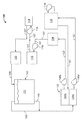
図1は、塩水処理システム100の例となる実施形態の概略図を示している。概して、塩水処理システム100は、塩水101の流れがその水源に戻る前に、塩水101の流れを受け入れ、塩水101の流れを濾過し、塩水101の流れを(例えば、機械的に、化学的に、生物学的に、又はそれらの組合せで)処理するように、塩水源102などの塩水源を含みうる、若しくはそれに流体的に結合されうる。幾つかの態様では、塩水源は、水族館又は再循環水産養殖システムなどの閉鎖タンクでありうる。閉鎖タンクは、幾つかの態様では、天然の海水源(例えば、大洋、海、又は他の起源)に流体的に結合されうる。代替的な態様では、閉鎖タンクは、天然の海水源に流体的に結合されていなくてもよく、例えば、天然の海水源に直接隣接していない地理的地域(例えば内陸地域)に位置していてもよい。幾つかの態様では、水族館又は再循環水産養殖システムとしての閉鎖タンクは、魚、哺乳類、甲殻類、及び他の動物などの生きた動物を支援することができる。
FIG. 1 shows a schematic diagram of an embodiment as an example of the salt
幾つかの態様では、飼育観賞用水槽システム及び再循環水産養殖システムは、このようなシステムのさまざまな目的に基づいて、さまざまな構成を有することができる。例えば、水族館は、単一の動物生息タンク、若しくは、水源を共有するように流体的に結合されているが、一のタンクに由来する動物は、典型的には又は決して別のタンクに移動しないであろうという点で独立している、複数の独立した動物生息タンクで構成することができる。幾つかの態様では、一又は複数の特定の動物は、その一生又はその一生の大部分を水族館システムの単一のタンク内で過ごしうる。水族館システムについての懸念は、タンク内の動物密度が特定の閾値を超えないように(例えば、動物の鑑賞が妨げられないように、動物の平均余命を最長化するようになど)、特定のタンク内で低い動物個体数を維持することを含みうる。 In some embodiments, the breeding ornamental aquarium system and the recirculating aquaculture system can have different configurations based on the different purposes of such a system. For example, aquariums are fluidly coupled to a single animal habitat tank or share a water source, but animals from one tank typically or never move to another tank. It can consist of multiple independent animal habitat tanks that are independent in that they will be. In some embodiments, one or more particular animals may spend their entire lives or most of their lives in a single tank of the aquarium system. Concerns about the aquarium system are that the density of animals in the tank does not exceed a certain threshold (for example, to maximize the life expectancy of the animal so that it does not interfere with the viewing of the animal). It may include maintaining a low animal population within.
対照的に、再循環水産養殖システム(RAS)は、動物を収容又は飼育する、1つ以上の淡水、汽水、又は塩水(人工型又は天然型)のタンクのシステム又は一連のシステムを含みうる。これらのタンクは、必ずしも生息地ではないが、最終的な収穫及び人間が消費するための動物の生命(例えば魚)の準備を目的として、動物の生活を支援する目的及び動物の急速な成長の目的で利用することができる。RASは、水1立方メートルあたりの魚の質量が数百キログラムなど、飼育観賞用水槽システムと比較して高い、一又は複数の動物飼養密度を有しうる。このようなRAS動物密度は、典型的な飼育観賞用水槽の設定の100倍超になりうる。 In contrast, a recirculating aquaculture system (RAS) may include one or more freshwater, brackish, or saltwater (artificial or natural) tank systems or a series of systems for accommodating or rearing animals. These tanks are not necessarily habitats, but for the purpose of supporting animal life and the rapid growth of animals for the purpose of final harvest and preparation of animal life (eg fish) for human consumption. It can be used for the purpose. The RAS may have one or more animal feeding densities, such as a fish mass of several hundred kilograms per cubic meter of water, which is higher than that of a breeding ornamental aquarium system. Such RAS animal densities can be more than 100 times higher than typical breeding aquarium settings.
これらの動物飼養密度は、しばしば、硝酸塩となる高レベルの溶存窒素並びに動物の呼吸による大量の二酸化炭素を生成する飼育観賞用水槽システムに対する動物飼料量(animal feed rates)を必要とする。飼育観賞用水槽システムなどのRASの濾過構成要素には、機械的、生物学的、及び化学的濾過が含まれうる。RASの幾つかの態様では、塩水源102内の高レベルの溶存二酸化炭素によるガス交換システムが(例えば、システム100内に)含まれうる。二酸化炭素は、RAS中での急速攪拌を利用して塩水101から機械的に除去され、負圧ダクトシステムで収集されうる。
These animal feed densities often require high levels of dissolved nitrogen to nitrate as well as animal feed rates for breeding ornamental aquarium systems that produce large amounts of carbon dioxide from the animal's respiration. Filtration components of RAS, such as breeding aquarium systems, can include mechanical, biological, and chemical filtration. In some aspects of the RAS, a gas exchange system with high levels of dissolved carbon dioxide in the salt water source 102 (eg, in the system 100) may be included. Carbon dioxide can be mechanically removed from the
システム100は、図1の例となる実施に示されるように、導管107(例えば配管)を通じて、砂濾過システム108、気泡分別システム110、脱窒システム112、オゾンシステム114、脱気システム120、及びリターンサンプ122などの複数の処理サブシステムに流体的に結合された、塩水源102を含む。システム100はさらに、この例では、塩水源102に由来する塩水の流れをシステム100の1つ以上の構成要素へと循環するように配置されている、ポンプ106a、106b、116、及び118も含む。
塩水源102は、この例では、魚及び他の動物などの動物の生命を支援する水族館又は再循環水産養殖システムを含む閉鎖タンク(例えば、周囲環境に対して上部が開放されている)である。導管、配管、及び上述のサブシステムを含むシステム100は、600万ガロン超の塩水101を保持又は含有できるのに対し、この例となる実施態様では、塩水源102は、約400万ガロンの塩水101を保持又は含有できる。システム100に囲まれた塩水101は、最初は淡水、塩、及び他の添加剤(例えば、化学物質)から製造することができ、あるいは、(利用可能な場合には)海水の天然資源からシステム100へと循環させてもよい。簡略化するために、化学添加剤システム、補給(make-up)塩水システム、栄養添加剤システム(動物飼育及び植物栽培用)などのシステム100のある特定の構成要素は、図1の概略図では省略されている。
The
示されるように、流体導管103及び105は、塩水源102をリターンサンプ122に連結している。流体導管105が塩水101の底の部分(例えば、塩水101の上面よりも30から40フィート深い)をリターンサンプ122に連結するのに対し、流体導管103は、塩水源102の塩水101の上面をリターンサンプ122に連結していている。幾つかの実施形態では、塩水101は、例えば、重力によって、塩水源102から表面スキマー(導管103)及び底部ドレーン(導管105)を通ってリターンサンプ122へと流れうる。リターンサンプ122は、この例では、壁で仕切られた2つのセクションである、チャンバ124aとチャンバ124bに分けられている。チャンバ124aは、導管103及び105によって、塩水源102に流体的に結合されている。チャンバ124aはまた、ポンプ106aを通じて、気泡分別システム110にも流体的に結合されている。チャンバ124bは、気泡分別システム110、並びにシステム100の他の構成要素から塩水101の流れを受け取るように流体的に結合されている。
As shown,
気泡分別システム110(すなわち、タンパク質スキミングシステム)は、概して、リターンサンプ122のチャンバ124aからチャンバ124bへと戻る再循環プロセスループを備えた複数のタンクを含む。気泡分別システム110は、気泡を生成するために空気/水を取り込むことによる溶存する有機廃棄物又は廃液の除去を目標としており、図示されるように、システム110のタンクを通じて塩水101の少なくとも一部を再循環するポンプ119を含みうる。水分子の極性及び気泡の表面張力は、これらの廃棄物に対する親和性を生み出し、これにより、システム110のタンクの上部から汚れた気泡を「分別」できるようにし、それによってプロセスから廃棄物を除去する。幾つかの態様では、このプロセスを強化するために、少量のオゾンガスを気泡分別システム110内の空気/水の流れに投入してもよく、また、塩水101の他の処理に役立つマイクロ凝集も作り出すことができる(例えば、砂濾過システム108内で)。
The bubble separation system 110 (ie, the protein skimming system) generally includes a plurality of tanks with a recirculation process loop returning from
砂濾過システム108は、リターンサンプ122のチャンバ124bに流体的に結合されており、塩水101の流れからの迅速な微粒子除去のために複数のタンクを含んでいる。砂濾過システム108は、ひとたび微粒子物質が充填されると、それらを浄化するために定期的に逆洗することもできる。水から粒子を機械的に濾過するほかに、砂濾過システム108はまた、後に詳しく説明するように、好気性従属栄養細菌の繁殖場所も作り出す。例えば、砂濾過システム108の各タンク内の速い水の流れ及び大きい表面積に起因して、幾つかの生物学的濾過、並びに機械的濾過が、動作中に行われる。例えば、砂濾過システム108のタンク内のバイオフィルムは、窒素、リン、及び有機炭素などの栄養素を合成することができる。幾つかの例では、砂濾過システム108は、およそ20μm以上の塩水流中の粒子を除去することができる。
The
この例に示されるように、脱窒システム112及びオゾンシステム114は、砂濾過システム108からシステム100を通じて塩水101の流れの一部を受け取るように流体的に結合されている。例えば、ポンプ118は、脱窒システム112を通じて塩水101の流れの一部を循環するように配置されているとともに、ポンプ116は、オゾンシステム114を通じて塩水101の流れの一部を循環するように配置されている。
As shown in this example, the
脱窒システム112は、示されるように、システム100を通って循環する塩水101の流れの一部を受け取る。概して、脱窒システム112は、塩水101の硝酸塩を亜硝酸塩へと生物学的に変換し、その後、亜酸化窒素へ、その後(潜在的に)窒素ガスへと変換する。例えば、飼育観賞用水槽及び再循環水産養殖システムでは、水を塩水源102の塩水101に取り換えるなど、水源の交換は、最終的に溶存硝酸塩(NO3)の形態となる食物及び動物の排泄物に由来する窒素をベースとした生成物の蓄積の理由から、必要でありうる。この硝酸塩は、窒素サイクルの硝化部の最終生成物として形成される場合があり、高濃度において、魚及び無脊椎動物などの飼育観賞用水槽内の動物に慢性的な健康問題を引き起こしうる。窒素サイクルの硝化部は好気性であり、水中で、並びに、好気性細菌及び溶存酸素の存在及び豊富さに起因して、閉じられた水族館又は再循環水産養殖システム内の物質上で容易に発生する。このような条件下で、硝化細菌と呼ばれるこれらの環境細菌は、主に排泄される動物老廃物であるアンモニアを亜硝酸塩へと、その後に硝酸塩へと容易に酸化する。硝酸塩をガス状窒素へと還元する窒素サイクルの脱窒部は、脱窒菌によって行われうる。脱窒菌は、幾つかの態様では、低酸素環境で硝酸塩化合物などの代替酸素源を利用する通性嫌気性細菌でありうる。これは、例えば、他の好気性環境では再現及び維持が困難である、望ましい又は要求された嫌気性条件を理由として、閉鎖系の水槽では達成がより困難でありうる。
The
塩水(又は淡水)中の高い硝酸塩濃度に関連する問題は、塩水(又は淡水)源では、1週間あたりの総量の10−30%の割合の水を取り換えることによって対処することができる。水の変化は、例えば、新しい塩水(例えば、製造された又は天然の塩水源に由来する)の別の一部もシステム内に循環させつつ、塩水の一部を閉鎖系の外へと循環させることを含む。新しい塩水(又は淡水)は、過剰の硝酸塩濃度の希釈に役立ち、したがって、動物のための健康な水化学を維持する。代替的に、脱窒システム112などの脱窒システムは、塩水中の硝酸塩のすべて又は一部を窒素ガスへと変換するために使用することができ、その後、塩水から除去することができる。
Problems associated with high nitrate concentrations in salt water (or fresh water) can be addressed in salt water (or fresh water) sources by replacing 10-30% of the total amount of water per week. Water changes, for example, circulate part of the salt water out of the closed system, while also circulating another part of the new salt water (eg, derived from a manufactured or natural salt water source) into the system. Including that. Fresh salt water (or fresh water) helps dilute excess nitrate concentration and thus maintains healthy hydrochemistry for animals. Alternatively, a denitrification system such as the
例となる実施形態では、脱窒システム112は硫黄脱窒システム112でありうる。例えば、硫黄脱窒(SDN)システムは、外部給餌又は炭素エネルギー源の補給をほとんど又は全く必要としない、独立栄養プロセスを実施することができる。対照的に、従属栄養性脱窒は、反応のエネルギー源とするために、通常は、エタノール又はメタノールの形態の炭素の外部補給に依存している。SDNプロセスは、硝酸塩(NO3)を亜酸化窒素(NxOx)へと還元し、最終的には窒素ガス(N2)へと還元する、硫黄を好む通性嫌気性細菌を培養する。それらの嫌気性の性質に起因して、SDNの適用は、低酸素圧を保持するように決定された水の流量で、元素硫黄を含む密閉型反応器内で行われうる。このような条件下で、チオバシラス・デニトリフィカンス(Thiobacillus・denitrificans)及び他の同様の硫黄を好む細菌などの細菌は、元素硫黄上で繁殖し、式1に示すように、硝酸塩を窒素ガスへと還元する:

硫黄は、細菌が生息する媒体であり、細菌の電子供与体又はエネルギー源としても機能する。脱窒プロセスはまた、利用可能な炭素を、二酸化炭素、炭酸塩及び重炭酸塩の形態で、反応の主要成分として消費する。天然海水中では容易に入手可能であるが、炭酸塩は、再循環SDNプロセスループ内では枯渇する可能性がある。塩水処理システム100の幾つかの態様では、SDNプロセスを補充し最適化するために、アラゴナイトなどの炭酸カルシウム源を、システム100内(又は脱窒システム112などのシステム100に流体的に結合された別のシステム内)に入れてもよい。
Sulfur is a medium in which bacteria live and also functions as an electron donor or energy source for bacteria. The denitrification process also consumes the available carbon in the form of carbon dioxide, carbonates and bicarbonate as the main component of the reaction. Although readily available in natural seawater, carbonates can be depleted within the recirculating SDN process loop. In some aspects of the salt
オゾンシステム114は、示されるように、システム100を通って循環する塩水101の流れの一部を受け取る。幾つかの態様では、オゾンガスをオンサイトで発生させて、システム100内の塩水に注入することができる。オゾンは、幾つかの例では、気泡分別システム110と、砂濾過システム108の下流のシステム100に位置するオゾンシステム114の一部としてのオゾン接触装置の両方において、注入することができる。オゾン接触装置は、色の除去、有機の除去及び塩水源102の消毒を含めた化学的濾過の形態として機能しうる。オゾンの酸化効果は、オゾンシステム114内のオゾン接触装置へのオゾンガスの流れを制御する酸化還元電位(ORP)センサを使用して測定される。気泡分別システム110(砂濾過システム108及び脱窒システム112を通じて)並びにオゾンシステム114からのオゾン化塩水は、脱気システム120へと循環される。
The
塩水源102に戻る前に、システム100の塩水101は、脱気システム120へと循環される。脱気システム120は、酸素及び二酸化炭素など、塩水101中の溶存ガスが大気と平衡になるようにバランスをとる、1つ以上の脱気塔を含む。幾つかの態様では、脱気システム120はまた、生物学的濾過が塩水中で生じるために有益なバイオフィルム成長場所でもありうる。処理された塩水101は、脱気システム120から、例えば導管109での重力送給によって、塩水源102へと戻るように循環されうる。
Before returning to the
図1には示されていないが、1つ以上の追加のシステム及びサブシステムもまた、塩水処理システム100の一部でありうる。例えば、1つ以上の熱交換器(例えば、プレート及びフレーム、シェル及びチューブ、又は他の形態の熱交換器)を、システム100内に、かつ、1つ以上の熱源(例えば、ボイラー)及び1つ以上の冷却源(例えば、冷却機)にも、熱的に結合することができる。例えば、幾つかの態様では、1つ以上の熱交換器の第1の側を、システム100内で導管107に流体的に結合することができるとともに、1つ以上の熱交換器の第2の側を、熱源、冷却源、又は両方に流体的に結合することができる。熱交換器の第1及び第2の側は、塩水101と加熱又は冷却源との間で熱を交換するように熱的に結合されうる。
Although not shown in FIG. 1, one or more additional systems and subsystems may also be part of the
塩水処理システム100はまた、1つ以上の濾過池(basins)に砂濾過逆洗排水を捕捉することができる、逆洗回収システムも含みうる。幾つかの態様では、少なくとも1つの「清浄な」濾過池及び少なくとも1つの「汚い」濾過池が存在しうる。一又は複数の汚い濾過池及び一又は複数の清浄な濾過池を使用して、砂濾過逆洗水を、システム100内の(これらの特徴について記載したように動作する)回収システムのための専用の砂濾過、気泡分別、及びオゾン接触を用いてバッチ処理することができる。ひとたびバッチ濾過され、一又は複数の清浄な濾過池へと回収されると、逆洗水は、再利用されて、塩水源102へと循環させることができる。
The salt
塩水処理システム100はまた、流量制御システムも含みうる。流量制御システムは、例えば、システム内の塩水101の細流をポンプで送るためのポンプ106a、106b、116、118、及び119、そこを通って細流が流れる導管103、105、107、及び109などの1つ以上のフロー管、並びに、管を通る塩水101の流れを調整するための1つ以上の弁を含みうる。幾つかの実施形態では、流量制御システムは、手動で操作することができる。例えば、オペレータは、各ポンプの流量を設定し、弁の開閉位置を設定することによって、流量制御システム内の管を通る塩水101の流れを調整することができる。ひとたびオペレータが塩水処理システム100に分散するすべての流量制御システムについて流量及び弁の開閉位置を設定すると、流量制御システムは、例えば、一定の容積率などの一定の流動条件又は他の流動条件下で、システム100内に塩水101を流すことができる。流動条件を変更するために、オペレータは、例えば、ポンプの流量又は弁の開閉位置を変更することによって、流量制御システムを手動で操作することができる。
The salt
幾つかの実施形態では、流量制御システムを自動的に操作することができる。例えば、流量制御システムをコンピュータシステムに接続して、流量制御システムを操作することができる。コンピュータシステムは、操作(流れ制御操作など)を実行するために1つ以上のプロセッサによって実行可能な命令(流れ制御命令及び他の命令など)を保存するコンピュータ可読媒体を含みうる。オペレータは、コンピュータシステムを使用して、塩水処理システム100に分散するすべての流量制御システムについての流量及び弁の開閉位置を設定することができる。このような実施形態では、オペレータは、コンピュータシステムを通して入力を提供することによって、流動条件を手動で変更することができる。また、このような実施形態では、コンピュータシステムは、流量制御システムの1つ以上を、例えば、塩水処理システム100内で実施され、かつコンピュータシステムに接続される、フィードバックシステムを使用して、自動的に(すなわち、手動介入することなく)制御することができる。例えば、センサ(例えば、圧力センサ、温度センサ、流量センサ、硝酸塩センサ、又は他のセンサ)を、そこを通って塩水101が流れる管に接続することができる。一又は複数のセンサは、塩水101の流動条件(例えば、圧力、温度、流量、硝酸塩濃度、又は他の流動条件)を監視し、コンピュータシステムに提供することができる。閾値(例えば、閾値圧力値、閾値温度値、閾値流量値、閾値硝酸塩濃度値、又は他の閾値)を超える流動条件に応答して、コンピュータシステムは、動作を自動的に行うことができる。
In some embodiments, the flow control system can be operated automatically. For example, the flow control system can be connected to a computer system to operate the flow control system. A computer system may include a computer-readable medium that stores instructions (such as flow control instructions and other instructions) that can be executed by one or more processors to perform an operation (such as a flow control operation). The operator can use a computer system to set the flow rate and valve open / close position for all flow control systems distributed in the
塩水処理システム100の例となる動作では、塩水101は、塩水源102からチャンバ124aへと循環される。幾つかの態様では、塩水源102は、約400万ガロンの塩水101を含んでよく、塩水の一部は、チャンバ124aへと連続的又は周期的に循環される。塩水101は、その後、気泡分別システム110へと循環されてよく、そこで、例えば、溶存する有機液及び廃液を除去することができ、オゾンを塩水101に入れることができる。幾つかの態様では、気泡分別システム110に循環される塩水101の量は、毎分約65,000ガロン(gpm)である。
In an example operation of the salt
塩水101は、気泡分別システム110からチャンバ124bに戻るように循環され、その後、砂濾過システム108へと循環され、そこで粒子状物質が塩水101から除去される。気泡分別システム110と同様に、砂濾過システム108は、約65,000gpmの塩水101を扱うことができる。
The
砂濾過システム108から循環された塩水101は、その後、脱気システム120へと循環される。例えば、気泡分別システム110及び砂濾過システム108を通って流れる65,000gpmの一部など、塩水101の一部は、脱窒システム112へと循環され、その後、オゾンシステム114に循環される。幾つかの実施形態では、脱窒システム112を循環し、その後、オゾンシステム114へと循環する小部分(例えば、50gpm、100gpm、200gpm、300gpm、400gpm又は別の体積流量)は、その後、脱気システム120へと循環する(塩水101の主流とともに)。ひとたびオゾンが塩水101に接触すると、硝酸塩は塩水101から除去され、塩水101中の溶存ガスは平衡化され、塩水101の流れは塩水源102へと戻される。
The
図2A−2Bは、塩水処理システムのための脱窒システムの例となる実施形態の概略図を示している。図2Aは、例えば、幾つかの態様では図1に示される脱窒システム112として実施されうる、硫黄脱窒システム200の例となる実施形態を示している。例えば、図2Aに示されるように、脱窒システム200は、塩水源102から塩水101の流れを受け取り、塩水101の流れを処理(例えば、脱窒プロセスを実施)し、処理された塩水101を塩水源102へと戻すように流体的に結合されている。
2A-2B show a schematic of an exemplary embodiment of a denitrification system for a saltwater treatment system. FIG. 2A shows, for example, an exemplary embodiment of the
図示するように、概して、脱窒システム200は、塩水源102に流体的に結合された再循環ループを含み、その再循環ループ内に、複数のタンク206を含む。再循環ループは、塩水源102に流体的に結合され、かつ、弁212を通って、タンク206の注入口に流体的に結合された、入口ヘッダ202を含む。再循環ループはまた、塩水源102に流体的に結合され、かつ、弁214を通って、タンク206の排出口に流体的に結合された、出口ヘッダ204も含む。出口ヘッダ204もまた同様に、例えば、バイパスヘッダ220及び弁222によって、入口ヘッダ202に流体的に結合されている。
As shown, in general, the
この例では、タンク206の少なくとも幾つかは、脱窒プロセスに用いられる媒体230及び細菌を保持することができる容積を画成する。例えば、幾つかの態様では、タンク206の少なくとも幾つかは、SDN中に、硝酸塩を、例えば、亜酸化窒素及び/又は窒素ガスへと変換するのに用いられる細菌(例えば、チオバシラス・デニトリフィカンス(Thiobacillus・denitrificans))を担持する硫黄媒体230を保持しうる。幾つかの例では、媒体230は、99.9%の元素硫黄の「プリル」で構成された硫黄媒体を含みうる。
In this example, at least some of the
さらには、この例では、該タンク206のうちの少なくとも1つは、炭酸カルシウム(CaCO3)又はアラゴナイト(すなわち、天然のCaCO3)などの炭酸カルシウム媒体240を保持することができる容積を画成しうる。例えば、示されるように、タンク206は、入口及び出口ヘッダ202及び204に対して並列に結合されており、及び幾つか(例えば、4つ)のタンク206が脱窒媒体230を保持するとともに、1つのタンク206は炭酸カルシウム媒体240を保持する。代替的な実施形態では、脱窒媒体230を保持する、より多くの又はより少ないタンク206が存在してもよく、炭酸カルシウム媒体240を保持する、より多くの又はより少ないタンク206が存在していてもよい。
Furthermore, in this example, at least one of the
この例では、炭酸カルシウム媒体240を保持するタンク206はまた、二酸化炭素(CO2)注入システム228も含む。例えば、幾つかの態様では、SDNは、pH約5.5の水pHで、さらに実施することができる。炭酸カルシウム媒体240(例えば、CaCO3、アラゴナイト、又は他の媒体)は、塩水101の特定の又は所定のpHの維持を助けることができるが、溶存する炭酸塩及び重炭酸塩を塩水101に提供すること(並びに、幾つかの事例では、豊富なこのような材料)によって、SDNプロセスに影響を与える可能性がある。幾つかの態様では、このような溶存する炭酸塩及び重炭酸塩は、効率(例えば、硝酸塩が亜酸化窒素又は窒素ガスへと変化する割合)を増加させることができる。幾つかの態様では、SDN反応は、CaCO3がタンク206の1つ以上に加えられた場合に、30−60%の間でより効率的になされうる(例えば、窒素ガス又はNxOxに対する硝酸塩の割合を増加させる)。
In this example, the
さらには、幾つかの態様では、CO2ガスの流れをタンク206へと送達する炭酸カルシウム媒体240を含むCO2注入システム228が、タンク206に流体的に結合されうる。ガス状CO2は、幾つかの実施形態では、塩水101の流れ内の炭酸カルシウム媒体240を溶解させるか、あるいはその溶解速度を増加させることができ、それによって、SDNの効率を増加させる(例えば、窒素ガスに対する硝酸塩の割合を増加させる)。幾つかの態様では、例えばRASでは、CO2の流れは、塩水101から溶存するCO2を除去するガス交換システム(この図には示されていない)から送達されうる。例えば、捕集されたCO2(例えば、ガス交換システムから)は、炭酸カルシウム媒体240を含むタンク206内の注入されたCO2を通じてシステム200内に導入されうる。
Furthermore, in some embodiments, a CO 2
幾つかの実施形態では、特定のタンク206(又は複数のタンク206)は、硫黄媒体230と炭酸カルシウム媒体240をともに保持しうる。例えば、幾つかの実施形態では、硫黄媒体230、脱窒菌、及びCaCO3(例えば、アラゴナイト)を、1つ以上のタンク206内で混合することができる。幾つかの態様では、細菌は自然に硫黄顆粒上に存在し、システム100のオペレータからの他の形態の追加又は補足を必要としないことがありうる。幾つかの態様では、複数のタンク206は、媒体230、細菌、及びアラゴナイトを含む場合があるとともに、他のタンク206は、硫黄媒体240/細菌又はアラゴナイトの一方又は他を含む場合がある。媒体240/細菌及びアラゴナイトの両方を含むタンク206では、炭酸カルシウム媒体240を硫黄媒体230の上に、例えば、8対1の硫黄のアラゴナイトに対する比で、配置することができる。媒体230及び240は、この構成で層別化かつ層状化されたままでありえ、よって、アラゴナイトの量を監視し、必要に応じて補充することを可能にする。他の態様では、アラゴナイトと硫黄媒体230を、同一のタンク206(又は複数のタンク206)内に、例えば、1対1の硫黄対アラゴナイトの割合で、この混合物の層別化又は層状化なしに、一緒にブレンドすることができる。
In some embodiments, the particular tank 206 (or tanks 206) may hold both the
この例では、各タンク206は、タンク206の排出口(例えば、タンク206と出口ヘッダ204の間)に逆洗ライン218を含む。幾つかの態様では、例えば、逆洗ライン218は、タンク206内で硫黄及びアラゴナイト媒体を(個別に又は組合せのいずれかで)洗い流し、したがって浄化可能になるように、開放されていてもよい。例えば、細菌性汚泥(例えば、従属栄養性)による媒体(例えば、媒体230又は240又は両方)の生物的汚染を低減するために、各タンク206への上昇流を別々に逆洗するか又は増加させること、並びに、回収システム(例えば、塩水源102で再利用するため)又は汚水渠に塩水101の一部を排出することが望ましい場合がある。幾つかの態様では、逆洗又は排出は、頻繁に起こりうる硫黄媒体230のチャネル化を元に戻すのに役立ちうる。例えば、逆洗は、水を安定して移動させ、できるだけ多くの硫黄と接触させるのに役立ちうる。チャネル化は、しばしば、効率を低下させ、有害な硫化水素ガスを放出しうる、過度に無酸素なゾーンを生じさせる可能性がある。
In this example, each
この例では、各タンク206はまた、タンク206の内容積に流体的に結合されたガス放出装置216も含む。幾つかの態様では、ガス放出装置216をタンクの容積206内の所定の圧力又は現在の圧力に基づいて自動的に操作して、ガス232の流れを周囲環境に放出することができる。例えば、ガス232は、タンク206内での脱窒プロセスによって生じる、亜酸化窒素及び/又は窒素ガスでありうる。別の例として、CO2などの他のガスを、ガス放出装置216を介して放出することができる。
In this example, each
追加のガス放出装置224は、この例に示されるように、バイパス導管220及び弁234の下流の出口ヘッダ204に配置される。膨張弁などのオリフィス234もまた、ガス放出装置224の上流の出口ヘッダ204に配置される。組合せにおいて、ガス放出装置224とオリフィス234は、窒素などのガスを周囲環境へとさらに放出するために、圧力降下をもたらすように動作しうる。例えば、システム200内の高い位置(及び、幾つかの態様ではシステム200内の最も高い位置)に配置されうる、オリフィス234及び隣接するガス放出装置224の組み込みにより、再循環ループの圧力が、ループの他の部分(例えば、タンク206、入口ヘッダ202)に比べて、低いか又は低下した領域を生じうる。この高位置低圧力領域において、塩水101内の窒素及び他のガスは、液体の外へと泡立ち、周囲環境へと放出されうる。例えば、圧力低下の結果としての相変化によって、新たに放出された窒素及び同様のガスは、再循環ループから直ちに排気することができ、したがって、このようなガスが溶液に溶解して戻る(例えば、ポンプ208によるループを介した塩水101のポンピングによる)のを防ぐことができる。
An
示されるように、別のガス放出装置224もまた、バイパス導管220(この例では、バイパス弁222の下流)に配置することができる。バイパス弁222及びガス放出装置242もまた、システム200の高い位置(及び、幾つかの態様ではシステム200内の最も高い位置)に配置することができる。述べたように、この高い配置により、ループの他の部分(例えば、タンク206、入口ヘッダ202)に比べて、再循環ループの圧力が、低いか又は低下した領域を生じうる。この高位置低圧力領域では、塩水101内の窒素及び他のガスは、液体の外へと泡立ち、バイパス導管220におけるガス放出装置224と連結して又は組み合わせて動作するバイパス弁222のすぐ下流に位置する周囲環境へと放出されうる。
As shown, another
例となるシステム200は、ポンプ208及び弁210を含む。ポンプ208(例えば、遠心ポンプ又は他の形態のポンプであり、ポンプ118と同じであってもよい)は、再循環ループを介して流れるように、(例えば、図1に示すように)塩水源102から塩水101を入口ヘッダ202内へと循環させることができる。幾つかの態様では、弁210を制御(例えば、調節)して、すべてのタンク206に循環する塩水101の流量を変動させることができる。代替的な態様では、弁210は、遮断弁又は調節弁であってよく、塩水101の流量を変動させるために、ポンプ208を(例えば、可変周波数駆動装置、ステップモーター、又は他の方法で)制御可能に変化させることができる。他の代替的な実施形態では、ポンプ208及び弁210は、再循環ループを介して、一定又は実質的に一定の流量の塩水101をもたらすことができる。
An
述べたように、弁212及び214は、それぞれ、タンク206の注入口及び排出口に配置される。幾つかの態様では、弁212及び214は、動作時に(例えば、手動又は自動)、再循環ループからタンク206を(個別に又は組み合わせて)流動的に隔離することができる、シャットオフ遮断弁(例えば、全閉又は全開可能)でありうる。代替的な態様では、弁212及び214の1つ以上は、動作時に、タンクへの塩水101の流量を(個別に又は組み合わせて)調節することができる、調節制御弁でありうる。
As mentioned, the
他の弁又は流量制御装置も、同様に、再循環ループ内に配置されうる。例えば、示されるように、調節弁222(例えば、自動又は手動、若しくはその両方)は、出口ヘッダ204から入口ヘッダ202へと循環する塩水101の流量を制御するように配置される。よって、制御弁222は、さらなる処理(例えば、硝酸塩のさらなる除去、炭酸塩添加、若しくはその両方)のために再循環ループ内を再循環する塩水101の流量を変動させるように、並びに、脱窒プロセスにおける展示水(exhibit water)の最適な水理学的滞留時間(HRT)を提供するように、制御されうる。よって、例となる脱窒システム200によれば、2つのループが存在してもよい。第1のループは、それぞれ、入口及び出口ヘッダ202及び204を含み、かつ、バイパスヘッダ220も含む。第2のループは、それぞれ、入口及び出口ヘッダ202及び204を含むが、バイパスヘッダ220は含まない。第1のループは、ポンピングされ、かつ、タンク206を介して再循環される(例えば、連続的に)とともに、第2のループは、塩水源102から第1のループへと流れ、再び塩水源102に戻る、少量の塩水101(例えば、塩水102中の塩水101の総体積に対して、又は塩水処理システム100を通って循環する塩水101の量に対して)を滴定する。
Other valves or flow control devices may be similarly placed in the recirculation loop. For example, as shown, the control valve 222 (eg, automatic and / or manual) is arranged to control the flow rate of the
幾つかの態様では、第1のループは、タンク206内の脱窒媒体230(例えば、硫黄)及び細菌の全容積及び表面積を効率的に利用するために、特定のパラメータ(例えば、圧力、速度)で循環される塩水101を含む。幾つかの態様では、このようなパラメータが満たされることを確実にするために、特定の容積の塩水101を、複数の通路内にタンク206を介してループさせて、その容積の塩水101の有効な(例えば、特定の硝酸塩濃度を達成する)脱窒を達成してもよい。幾つかの態様では、このような複数の通路は、例えば、タンク206内の媒体体積量に対して、より良好に有効な脱窒を達成することができる。よって、有効な脱窒を、従来の脱窒システムと比較して、より小さいタンクを有するシステム200で達成することができる。
In some embodiments, the first loop provides specific parameters (eg, pressure, velocity) to efficiently utilize the total volume and surface area of the denitrifying medium 230 (eg, sulfur) and bacteria in the tank 206. ) Contains the
幾つかの態様では、第2のループ(例えば、塩水源102からの及び塩水源102への)を通る塩水101の流量は、第1のループ内の塩水の流れ101に負担をかけないように制御されうる。例えば、第2のループ内へと循環する塩水101が多すぎると、第1のループで有効な脱窒が起こらないかもしれず、溶存酸素レベルが上昇する可能性があり、全体の硝酸塩濃度は、例えば、塩水101中の食物及び動物の排泄物に起因して、上昇するか、あるいは低下しない可能性もある。
In some embodiments, the flow rate of the
システム200の例となる動作において、塩水源102からの塩水101は、入口ヘッダ202内へ、かつ、並行して、タンク206へと循環される。幾つかの態様では、各タンク206を循環する塩水101の流量は、同様、実質的に同様、又は同一である。少なくとも一部のタンク206内で、塩水101は、媒体230及び脱窒菌を通って流れ、脱窒プロセスは、前述のように、塩水101内の硝酸塩を窒素ガスへと変換する。亜酸化窒素又は窒素ガスは、ガス放出装置216を通ってタンク206から放出される。示されるように、少なくとも1つのタンク206内で、塩水101は、媒体240を通って流れ、それを通して炭酸カルシウム(例えばアラゴナイト)添加プロセス並びにpH平衡化プロセス(例えば、pHは最低でも少なくとも5.5に維持される)が起こる。さらには、媒体240は、CaCO3又はアラゴナイトを含むことから、このような媒体は、少々、塩水101に溶解する。幾つかの態様では、CO2注入装置は、ガス状のCO2を炭酸カルシウム媒体240を保持するタンク206内に導入し、それによって、さらに、塩水101にCO2及び炭酸塩を溶解させるか、あるいはそれらの溶解速度を増加させる。処理された塩水101は、タンク206から出口ヘッダ204内へと流れる。処理された塩水101の一部は、バイパスヘッダ220を介して入口ヘッダ202へと戻るように流れるとともに、処理された塩水101の別の一部分は、塩水源102へと戻るように流れる。バイパスヘッダ220を通って流れる処理された塩水101の一部は、塩水源102からの塩水101の追加の流れに合流してよく、タンク206へと戻るように循環されうる。
In an example operation of the
この例の追加の動作又は態様では、温度制御システム242が、例えばバイパス導管220内など、システム200内に含まれていてもよい。例えば、温度制御システム242内の熱源は、システム200の再循環ループ内の塩水101を加熱するように動作しうる(例えば、ガス、電気、太陽、又は他のエネルギー形態によって作動する)。例えば、温度制御システム242は、再循環ループ内の塩水の温度を(例えば、設定温度として)20℃又は約20℃から22℃に維持するように、(例えば、自動又は手動で)動作しうる。温度制御システム242は、バイパス導管220内の塩水101及び熱源の温度を測定するサーモスタットを含みうる。幾つかの態様では、温度制御システム242は、熱源を含まなくてもよいが、システム242からの温度測定値に基づいてシステム200内の熱源を制御するコントローラに通信可能に接続されうる。
In an additional operation or embodiment of this example, the
この例の別の例となる動作又は態様では、オゾンガス注入及び加圧タンク接触システム244は、塩水101をタンク102へと戻す前に処理するために、システム200内(例えば、オリフィス234及びガス放出装置224の下流)に含まれうる。幾つかの態様では、このオゾンガス注入及び加圧タンク接触システム244を、図1に示されるオゾンシステム114に加えて、動作させることができる。幾つかの態様では、このオゾンガス注入及び加圧タンク接触システム244を、図1に示されるオゾンシステム114の代わりに動作させることができ、幾つかの事例では、オゾンシステム114に代えて使用することができる。よって、幾つかの態様では、脱窒システム200は、単一のパッケージとしてオゾンシステム(本開示による)を含みうる。動作中、硫黄脱窒プロセスは、未処理のままにしておくと塩水源102に生息する動物にとって有害になりうる化学種の減少を生じうる。塩水源102に戻る前に塩水101を酸化させることによって、例えば、塩水源102(例えば、水族館又は水産養殖環境)に生息する動物への有害な影響を与えないことを確実にするために、このような廃水を処理することができる。オゾンガス注入及び加圧タンク接触システム244は、システム244から塩水101へのオゾンの用量を制御するために、塩水101が酸化又は還元剤として作用する能力を測定する、酸化還元電位(ORP)センサを含みうる。ORPセンサは、動作中、コントローラへのフィードバックを提供し、これにより、今度は、システム244、オゾンシステム114、若しくはその両方が制御されて、塩水101のORP値を、200ミリボルトを上回るが400ミリボルトを超えないように維持することができる。
In another exemplary operation or embodiment of this example, the ozone gas infusion and pressure
図2Bを見ると、この図は、幾つかの態様では、図1に示される脱窒システム112として実施することができる、硫黄脱窒システム250の例となる実施形態を示している。図2Bに示されるように、システム250は、概して、塩水源102から塩水101の流れを受け取り、塩水101の流れを処理し(例えば、脱窒プロセス及びpH平衡化プロセスを通じて)、処理された塩水101の少なくとも一部を塩水源102へと戻すように流体的に結合された、2つの脱窒システム200を含む。よって、脱窒システム250内では、各システム200は、独立して、あるいは、塩水101の脱窒、pH平衡化、又はその両方を提供するように協力して、動作及び制御することができる、サブシステムでありうる。さらなる例となる脱窒システムは、例えば、塩水源102と並列に流体的に結合されている、3つ以上のサブシステム200を含みうる。また、システム250内の各サブシステム200は、脱窒媒体230を有するより多くの又はより少ないタンク206、並びに、炭酸カルシウム媒体240を含むより多くの又はより少ないタンク206を含めた、より多くのタンク206又はより少ないタンク206を含みうる。システム250内の各サブシステム200の例となる動作は、先に説明したものと同様であってよく、サブシステム200ごとに独立して(例えば、各サブシステム200の構成要素は、異なるパラメータ又は所望の出力に制御されうる)又はタンデムで(例えば、各サブシステム200の構成要素は、同一又は同様のパラメータ又は所望の出力に制御されうる)、実施することができる。
Looking at FIG. 2B, this figure shows an exemplary embodiment of the
図3A−3Cは、脱窒システムのためのタンク300の例となる実施形態を示している。幾つかの態様では、タンク300は、図2A及び2Bに示されるタンク206の1つ以上と同様又は同一でありうる。よって、タンク300は、脱窒プロセス(例えば、脱窒媒体230を用いる)、pH平衡化及びアラゴナイト添加プロセス(例えば、炭酸カルシウム媒体240を用いる)、若しくはその両方似利用されうる。図3Aは、タンク300の側面断面図を示している。図3Bは、塩水注入マニホールド312を含むタンク300の底の部分の平断面図を示している。図3Cは、塩水排出口310を含むタンク300の頂部の平断面図を示している。
FIG. 3A-3C shows an exemplary embodiment of the tank 300 for a denitrification system. In some embodiments, the tank 300 may be similar or identical to one or more of the
タンク300は、この例では、容積を取り囲み、基部306に支持されているシェル302を含む。この図では、タンク300は垂直に配向されるように示されているが、例えば、容積の長軸は、タンク300を支持する床に対して垂直に配向される。よって、長軸は、重力の方向に位置合わせされる。幾つかの態様では、図2A−2Bに示されるタンク206の各々もまた、垂直に位置合わせされる。タンク300を垂直に位置合わせすることによって、タンク300内で処理される塩水の流れは、プロセス媒体322(例えば、脱窒菌を担持する硫黄などの脱窒媒体、又はCaCO3などの炭酸カルシウム媒体)との十分な接触及び十分な接触時間を達成する。例となるタンク300では、媒体322は、脱窒菌を担持する硫黄でありうる。硫黄322はまた、シェル302の底の部分に配置された玉砂利324床に担持されていてもよい。
The tank 300, in this example, includes a
シェル302は、複数の付属物を含む。例えば、アクセスパネル304及び308は、示されるように、それぞれ、シェル302の下側及び上側部分に配置されうる。このようなアクセスパネル304及び308は、人によるアクセス又はシェル302の容積への視覚的アクセス(例えば、検査のため、清掃のためなど)を提供するように開閉可能でありうる。さらには、試料ポート320は、例えば、媒体322並びに該媒体322中を流れる塩水の採水を手動で行うために、シェル302に沿って垂直に配置されうる。
The
図3Bにより明確に示されるように、塩水注入マニホールド312は、ヘッダ316を介して複数の排出口分岐314と流体的に結合されている注入口318を含む。シェル302に近接している排出口分岐314の終端は、塩水が注入口318から、ヘッダ316を介して、及び分岐314を通じてシェル302の容積内へと流れることができるように開口部を含む。示されるように、排出口分岐314は、玉砂利324内にシェル302の容積にわたり(例えば、均等に)分散される。幾つかの態様では、このような分散は、容積を通じてシェル302の底の部分から鉛直上方に、塩水排出口310への塩水の均一又は実質的に均一な流れを提供しうる。幾つかの態様では、1つ以上の排出口分岐314は、分岐314の長さに沿って配置された穿孔又は微細加工したスリットを有してよく、それによって、媒体が排出口分岐314に流れ込む又は入ることなく、穿孔からの塩水取出口を提供する。代替的な実施形態では、複数の排出口を有するマニホールドではなく、シェル302内への単一の塩水注入口が存在しうる。さらなる代替的な実施形態では、排出口分布マニホールドを、注入マニホールド排出口312と同様に、穿孔又は細断されたスリットとともに利用することができる。例えば、排出マニホールドを、容器302内の媒体322が排出口310に逃げるのを防止するか、あるいは防止に役立てることができる。追加的に、この目的のため、スクリーン、有孔板、又は他の封じ込め機構を利用して、媒体322がタンク300から逃げるのを防ぐことができる。
As clearly shown in FIG. 3B, the salt
この例では、塩水排出口310は、容器側壁302の上部に配置され、シェル302の垂直軸と一直線になっている。代替的な実施形態では、塩水排出口310は、シェル302の上部に配置することができるが、シェル302の垂直軸から、若しくは上部近くのシェル302の側面からオフセットされてもよい。
In this example, the
動作中、塩水は、注入口318を通して塩水注入マニホールド312内へと循環される(例えば、強制的に)。塩水は、例えば、分岐314における貫通孔又は微細加工したスリットなどのマニホールド312の分岐314、該分岐314の終端の排出口、又はその両方から出る。塩水は、玉砂利324を通って媒体322内へと循環される。脱窒タンク300の場合には、塩水は、脱窒菌を担持する媒体322を通じて循環される。脱窒プロセスは、前述のように、媒体322において生じる。硝酸塩は、細菌によって、亜硝酸塩へと変換され、その後、亜酸化窒素及び/又は窒素ガスへと変換され、これは、シェル302の上部に配置されたガス排出接続326に接続可能なガス放出装置を通じてタンク300から出ることができる。pHバランシングタンク300の場合には、媒体322は、塩水に溶解するCaCO3又はアラゴナイトを含みうる。処理された塩水は、媒体322からシェル302の上部へと流れ、塩水排出口310を通ってタンク300から出る。
During operation, salt water is circulated (eg, forcibly) into the salt
図4は、脱窒システムのための制御システム400の概略図を示している。例えば、制御システム400は、例えば、脱窒システム112、脱窒システム200、脱窒システム250、又は本開示に従う他の脱窒システムを制御するために用いることができる。図示するように、制御システム400は、データベース404に通信可能に接続されたコントローラ402(例えば、マイクロプロセッサベース、PLC、電気機械式、空気圧式、又は他の形態のコントローラ)、並びに、供給口(コントローラ402への接続矢印で示される)及び取出口(コントローラ402から離れる接続矢印で示される)を含む。コントローラ402及びデータベース404の一方又は両方は、コントローラ402を用いて、(例えば、制御システム400のオペレータによって提供される)入力および設定値を出力に変換して、脱窒システムの1つ以上の構成要素を制御する、非一時的コンピュータ可読媒体にコード化された命令を保存することができる。
FIG. 4 shows a schematic diagram of a control system 400 for a denitrification system. For example, the control system 400 can be used, for example, to control a
図示するように、コントローラ402に供給口を提供する、脱窒システムの複数の構成要素が存在する。例えば、硝酸塩濃度センサ406は、塩水の流れの硝酸塩濃度を測定するために(例えば、ppm又は他の単位で)、脱窒システム内(例えば、硝酸塩を含む塩水又は淡水の流れを運ぶ流れ導管内、脱窒タンク内、若しくは塩水と接触する他の場所)に位置付けられうる。硝酸塩濃度の測定値(例えば、パーセンテージ又は絶対値として)は、コントローラ402に送信されうる。幾つかの態様では、硝酸塩濃度センサ406は、脱窒システムに入る塩水の流れと脱窒システムを離れる塩水の流れとの硝酸塩濃度の差を測定することができる。幾つかの例では、硝酸塩濃度センサ406は、Hach CompanyのNITRATAXでありうる。別の例として、センサ406は、OTT Hydromet社のSea−Bird Coastal SUNA光学式硝酸塩センサでありうる。幾つかの態様では、センサ406は、硝酸塩を測定するための光電池を備えた試薬ベースの分析装置を含みうる。センサ406は、例えばコントローラ402を介した、プロセス機器の制御のためのオンボード24VDCリレーで、4−20mAの信号を出力することができる。
As shown, there are multiple components of the denitrification system that provide a supply port to the
コントローラ402はまた、1つ以上の差圧センサ408(例えば、本明細書には2つのセンサとして示されている)からの差圧(DP)測定値も受け取ることができる。例えば、図2Aに示される脱窒システム200に関して、DPセンサ408は、ポンプ208にわたる、並びに、出口ヘッダ204と入口ヘッダ202との間の流体圧力差を測定するように配置されうる。このような測定値は、例えば、システム200の再循環ループを通って流れる塩水の相対的な流量を決定するために、コントローラ402において使用することができる。
コントローラ402はまた、1つ以上の流量計410(例えば、ここで示されているのは5つであるが、それより多い又は少ない数もまた予定されている)及び412(示されているのは2つであるが、それより多くても少なくてもよい)からの入力も受け取りうる。例えば、幾つかの態様では、流量計410は、各個別のタンク206を通る塩水の流量を測定するために、図2Aに示されるシステム200の各タンク206の注入口又は排出口に配置されうる。幾つかの態様では、流量計412は、例えば、再循環ループの入口ヘッダ202、出口ヘッダ204、又はバイパスヘッダ220の1つ以上にも配置されうる。各流量計410/412は、流量計410/412が配置される特定の場所における塩水の流量を(gpm又は他の単位で)測定し、コントローラ402に測定値を提供することができる。
コントローラ402はまた、温度制御システム(例えば、図2Aに示される温度制御システム242)の一部であるサーモスタット又は温度センサ428からの入力も受け取ることができる。サーモスタット428は、例えば、脱窒システム内の塩水の流れの温度の測定値を周期的に提供することができる。今度は、コントローラ402は、脱窒システムの再循環ループ(例えば、ループのバイパス導管内又は他の場所)に配置された温度制御システムのヒーターシステム424にも通信可能に接続されうる。
コントローラ402はまた、ORPセンサ430からの入力も受け取ることができる(例えば、図2Aに示されるオゾンガス注入及び加圧タンク接触システム244の一部として)。ORPセンサ430は、酸化又は還元剤として作用する塩水101の能力を測定することができる。今度は、コントローラ402は、2つの別々のオゾンシステムを含む場合に、例えば、オゾンガス注入及び加圧タンク接触システム244、オゾンシステム114、若しくはその両方など、オゾンシステム426を制御するために、通信可能に接続される。
コントローラ402はまた、溶存酸素(DO)センサ432からの入力も受け取りうる。DOセンサ432は、塩水中の溶存酸素の量を測定するように、脱窒システムに配置されてもよい。例えば、幾つかの態様では、酸素センサは、塩水中の溶存酸素の濃度を測定するために、再循環ループ内(例えば、入口ヘッダ、出口ヘッダ、バイパスヘッダにおけるタンクの1つ以上の注入口又は排出口又はその近く)に置かれてもよい。幾つかの態様では、例えば、脱窒システムが通性脱窒菌を使用する独立栄養脱窒システムである場合などでは、脱窒プロセスは、酸素濃度が比較的低く保たれているときに最も有効でありうる。例えば、通性嫌気性細菌は、嫌気性環境に存在する場合には、代替的な酸素源として、硝酸塩などの代替的な酸素源を利用する。よって、硫黄脱窒システム内の細菌は、環境が嫌気性の場合に、硝酸塩を窒素ガスへと、より効率的に変換することができる。しかしながら、このような生息場所に要求される嫌気性条件(例えば、動物の要求)に起因して、嫌気性条件は閉鎖系の飼育観賞用水槽では達成することが困難でありうる。
図示するように、コントローラ402は、脱窒システム200などの脱窒システムの複数の構成要素の動作を制御するように通信可能に接続されうる(例えば、無線又は有線)。例えば、コントローラ402は、例えば、図2Aに記載のCO2注入装置228でありうる、CO2注入装置414に通信可能に接続されうる。コントローラ402は、それぞれ、例えば、バイパスヘッダ220及び脱窒システム200の入口ヘッダ202に配置された、制御弁416にも通信可能に接続されうる。コントローラ402はまた、脱窒システム200のタンク206の注入口及びタンク206の排出口にそれぞれ配置された、制御弁418及び420にも通信可能に接続されうる。コントローラ402はまた、1つ以上のポンプ422にも通信可能に接続されうる(ここでは1つ表示されているが、それより多くても少なくてもよい)。例えば、ポンプ422は、脱窒システム200に示される再循環ポンプ208を表しうる。
As shown, the
幾つかの態様では、弁416は、それを通って循環する塩水の流量を調節するために、全開と全閉の間で制御可能に調節することができる。対照的に、弁418及び420は、全閉又は全開するように制御可能に動作させることができる。しかしながら、代替的な実施形態では、各弁416/418/420は、調節弁でありうる(例えば、全開と全閉の間で調節するように制御される)。
In some embodiments, the
幾つかの態様では、ポンプ422もまた、オン(例えば、フルパワー又は銘板電力)又はオフ(例えば、無電力)になるように制御されうる。よって、弁416/418/420の1つ以上の動作により、脱窒システムを循環する塩水の流量を制御することができる。弁416/418/420の各々の動作に基づいて、塩水の一部は、脱窒システム内の塩水の他の部分と比較して、異なる流量で流れうる。特定の例となる実施形態では、ポンプ422は、塩水を一定又は実質的に一定の流量で循環させるように制御することができると同時に、バイパスヘッダ(例えば、バイパスヘッダ220)に配置された弁416は、脱窒システム内を通る塩水の流量を制御するように調節される。弁418/420は、この例となる実施形態では、全開又は全閉となるように制御される(制御システム400を用いて又は手動で)、遮断弁でありうる。
In some embodiments, the
別の特定の例となる実施形態では、ポンプ422は、可変周波数駆動、ステップモーター、又は他のモーターコントローラなどによって、塩水の流量を変動させるように制御することができる。この特定の実施形態では、弁416/418/420はすべて、遮断弁(例えば、全開又は全閉)であってよく、ポンプ422は、脱窒システムの再循環ループ内の塩水の流量の制御かつ調節する責を負う。幾つかの事例では、この例においても、バイパスヘッダ内の弁416は調節弁でありうる。
In another particular exemplary embodiment, the
コントローラ402は、先に記載した例となる入力を受け取り、コントローラ402に命令として保存された1つ以上の運用アルゴリズムにおけるデータベース404に保存された入力値及び設定値の1つ以上を使用して、脱窒システムの構成要素を制御することができる。コントローラ402の例となる動作では、硝酸塩濃度測定値は、硝酸塩濃度406からコントローラ402へと送られうる。幾つかの事例では、この測定値は、動的に(例えば、塩水が脱窒システムを通って流れる際にリアルタイムで)、かつ周期的に(例えば、毎分、毎時、毎日、または他の期間)、送信されうる。コントローラ402は、塩水中の測定された硝酸塩濃度を、例えば、オペレータによって設定され、コントローラ402又はデータベース404に保存された、硝酸塩の設定値(又は設定範囲)と比較する。測定された濃度が設定値以下の場合には、コントローラ402は何も実行しない。
The
測定された濃度が設定値又は設定範囲の上限を超えている場合には、コントローラ402は、塩水内の硝酸塩の濃度を低下させるために、脱窒システムの1つ以上の構成要素に信号を供給しうる。例えば、コントローラ402は、弁の開放状態のパーセントを増加させるために、バイパスヘッダの弁416(あるいは、独立して又は組み合わせて弁416/418/420のいずれか)に信号を送ることができる。幾つかの態様では、例えば、バイパスヘッダの弁416が開くと、脱窒タンクの排出口からより多くの塩水が、脱窒タンクの注入口に戻るように循環する。これにより、脱窒システム内(例えば、脱窒システムの再循環ループ内)の塩水の水理学的滞留時間が増加しうる。脱窒システム内の塩水の水理学的滞留時間が増加すると(例えば、複数回通過すると、特定の容積の塩水が、脱窒タンクを通って流れる)、より多くの硝酸塩が、亜硝酸塩へ、その後、窒素ガスへと変化し、それによって、塩水中の硝酸塩濃度を低下させることができる。コントローラ402が硝酸塩濃度センサ406から追加の硝酸塩濃度測定値を受け取ると、コントローラ402は、弁416を開放し続けるか、あるいは、弁416の開放を終止することができる(例えば、測定された値が設定値未満のとき)。
If the measured concentration exceeds a set value or the upper limit of the set range,
コントローラ402はまた、脱窒システムの再循環ループ内を循環する塩水の流量を低下させるために、ポンプ422にも、若しくは代替的にポンプ422に、信号を送ってもよい。例えば、ポンプ220の速度が落ちると、再循環ループ内の塩水は、脱窒タンクを通って(例えば、底部から上部へと垂直に)循環するのに、より長い時間がかかる。これにより、脱窒システム内(例えば、脱窒システムの再循環ループ内)の塩水の水理学的滞留時間も増加させることができ、それによって、前述のとおり、脱窒プロセスにおける硝酸塩の窒素ガスへの変化の速度を増加させることができる。コントローラ402が硝酸塩濃度センサ406から追加の硝酸塩濃度測定値を受け取ると、コントローラ402は、ポンプ422のスピードを低下させ続けるか、あるいは、ポンプ422のスピードの変更を終止することができる(例えば、測定値が設定値未満のとき)。
コントローラ402は、脱窒システムのpHバランシングタンクに注入されるCO2の量を増加させるために、CO2注入装置414にも、若しくは代替的にCO2注入装置414に、信号を送ってもよい。例えば、より多くのCO2がpHバランシングタンク内に注入されると、タンク内のCaCO3又はアラゴナイトは、より迅速に塩水中に溶解しうる。再循環ループの塩水内のCaCO3又はアラゴナイトの濃度が増加するにつれて、脱窒プロセスもまた増加しうる。コントローラ402が硝酸塩濃度センサ406から追加の硝酸塩濃度測定値を受け取ると、コントローラ402は、pHバランシングタンク内に注入される速度を増加させ続けるか、あるいは、CO2の注入速度を一定に保つことができる(例えば、測定値が設定値未満のとき)。
The
別の例となる動作では、コントローラ402は、センサ428からの温度測定値を設定温度と比較し、該比較に基づいて、ヒーター424(又は、1つ以上の弁416/418などの他の構成要素)を動作させて、塩水の流れを所定の設定点又はそれ以上に維持することができる。例えば、測定された温度が低すぎる場合には、ヒーター424は、作動させるか、又は電力を増加させることができ、あるいは、1つ以上の弁416/418は、流れを制限して、塩水の流れを加熱するように調整することができる。
In another exemplary operation, the
他の例となる動作では、DOセンサ432は、塩水中の溶存酸素の量を測定し、コントローラ402に測定値を提供する。コントローラ402は、測定されたDOを、例えば、オペレータによって設定され、コントローラ402又はデータベース404に保存されたDOの設定値に対して比較することができる。幾つかの態様では、設定値は、脱窒が起こるための最小値と考えられる、約3.0mg/l又は40%の飽和を下回りうる。幾つかの態様では、設定値は、理想的なSDNが起こるためには、約0.10mg/lから2.0mg/lの間でありうる。
In another exemplary operation, the
DOの測定値は、センサ432からコントローラ402へと動的に(例えば、塩水が脱窒システムを通って流れる際にリアルタイムで)、かつ周期的に(例えば、毎分、毎時、毎日、または他の期間)、送信されうる。測定されたDOが設定値以下(又は設定範囲内)の場合には、コントローラ402は何も実行しなくてよい。測定された濃度が設定値より大きいか、又は設定範囲外の場合には、コントローラ402は、塩水内の酸素の濃度を低下させるために、脱窒システムの1つ以上の構成要素に信号を提供しうる。例えば、DO濃度を低下させるために、コントローラ402は、入口ヘッダにおいて弁416を制御して、供給源から脱窒システムへと、より少ない塩水を循環させることができる。脱窒システムへの塩水の流量を低減することによって、循環する塩水の水理学的滞留率は増加し、DOは低下する。
DO measurements are dynamically (eg, in real time as salt water flows through the denitrification system) and cyclically (eg, every minute, every hour, every day, or other) from
他の例となる動作では、理論的な硝酸塩除去をコントローラ402によって計算することができる。例えば、コントローラ402は、脱窒システムを通過し、塩水の水源へと戻る(例えば、第2のループ)流量の測定値、並びに、入ってくる硝酸塩濃度と出ていく硝酸塩濃度(例えば、第2のループに入り、第2のループから出ていくなど)との差異を使用して、理論的な硝酸塩除去を計算することができる。このような差異は、SDNプロセスのデルタ硝酸塩であってよく、コントローラ402で使用して、SDNプロセスの正味の硝酸塩フラックスを計算することができる。この正味の硝酸塩フラックスは、入力として表示することができ、場合によってはコントローラ402の設定値として入力され、したがってコントローラ402が達成又は維持しようと試みるための出力を作成することができる。
In another exemplary operation, theoretical nitrate removal can be calculated by
コントローラ402は、これらのプロセス中に、センサ408からの差圧値及びセンサ410及び412からの流量値など、他の値も周期的に受け取ることができ、このような値を差圧及び流量の対応する設定値(又は設定範囲)と比較して、このような測定値が許容範囲内にあることを確実にすることができる。例えば、コントローラ402は、脱窒システム内のセンサから差圧値、流量、温度、及び他の測定値などのこのような測定値を周期的に受け取り、このような値を、これらの値に関連した保存された設定値(又は設定範囲)(例えば、制御システム400のオペレータによって設定される)と比較する、フィードバックループを実行することができる。測定された値が設定値を満たさない(又は設定範囲外にある)場合には、コントローラ402は、測定値が設定値を満たすまで、又は設定範囲内になるまで、1つ以上の構成要素(例えば、弁416/418/420、ポンプ422、又は他の構成要素)を調整することができる。
During these processes, the
幾つかの態様では、コントローラ402は、流量、温度、溶存酸素、pH、又はORPなどの入力装置の値を比較することができ、また、測定値を、データベース404に設定可能な所定の警報パラメータと比較することができる。入力パラメータが安全範囲外であると測定された場合には、実行可能なアクションを実行してシステムをシャットダウンするか、あるいは、通常の運転状態が再確立される前にオペレータがクリアしなければならない「ロックアウト」状態を作り出すことができる。警報はまた、無線またはIP接続を使用して、電話またはテキストベースのメッセージとして送信される可視、可聴、又は通知アラームを含む取り出し装置として生成することもできる。
In some embodiments, the
図5は、制御システム400のコントローラ402など、制御システムのためのコントローラ500の概略図である。コントローラ500を使用して、注入物質検出システム及びプロセスの実行など、幾つかの実行に従う、前述のコンピュータ実行方法のいずれかに記載される動作を行うことができる。幾つかの実施形態では、本明細書に記載されるコンピューティングシステム及び装置、並びに機能動作は、本明細書に開示される構造(例えば、制御システム400)及びそれらの構造的な等価物を含む、デジタル電子回路内、有形に具現化されたコンピュータソフトウェア又はファームウェア内、コンピュータハードウェア内、若しくはそれらの1つ以上の組合せで実行されうる。コントローラ500は、ラップトップ、デスクトップ、ワークステーション、携帯情報端末、サーバー、ブレードサーバー、メインフレーム、及びモジュール式車両のベースユニット又はポッドユニットに取り付けられた車両を含めた他の適切なコンピュータなど、さまざまな形態のデジタルコンピュータを含むことが意図されている。コントローラ500には、携帯情報端末、携帯電話、スマートフォン、及び他の同様のコンピューティング機器などの携帯機器もまた含まれうる。追加的に、システムは、ユニバーサル・シリアル・バス(USB)フラッシュドライブなどの可搬記憶媒体を含みうる。例えば、USBフラッシュドライブは、オペレーティング・システム及び他のアプリケーションを保存することができる。USBフラッシュドライブは、別のコンピューティングデバイスのUSBポートに挿入可能な無線送信機又はUSBコネクタなどの入力/出力構成要素を含みうる。
FIG. 5 is a schematic diagram of a
コントローラ500は、プロセッサ510、メモリ520、記憶装置530、及び入力/出力装置540を含む。構成要素510、520、530、及び540の各々は、システムバス550を使用して相互接続されている。プロセッサ510は、コントローラ500内で実行する命令を処理することができる。プロセッサは、複数のアーキテクチャのいずれかを使用して設計することができる。例えば、プロセッサ510は、CISC(複合命令セットコンピュータ)プロセッサ、RISC(縮小命令セットコンピュータ)プロセッサ、又はMISC(最小命令セットコンピュータ)プロセッサでありうる。
The
実施形態では、プロセッサ510はシングルスレッドプロセッサである。別の実施形態では、プロセッサ510は、マルチスレッドプロセッサである。プロセッサ510は、入力/出力装置540上にユーザインタフェースのためのグラフィック情報を表示するために、メモリ520又は記憶装置530に保存されている命令を処理することができる。
In an embodiment, the
メモリ520は、コントローラ500内に情報を保存する。一実施形態では、メモリ520は、コンピュータ可読媒体である。一実施形態では、メモリ520は揮発性メモリユニットである。別の実施形態では、メモリ520は不揮発性メモリユニットである。
The
記憶装置530は、コントローラ500のための大容量記憶を提供することができる。一実施形態では、記憶装置530は、コンピュータ−可読媒体である。さまざまな異なる実施形態では、記憶装置530は、フロッピーディスク装置、ハードディスク装置、光ディスク装置、又はテープ装置でありうる。
The
入力/出力装置540は、システム500の入力/出力操作を提供する。一実施形態では、入力/出力装置540は、キーボード及び/又はポインティング装置を含む。別の実施形態では、入力/出力装置540は、グラフィカルユーザインターフェースを表示するための表示装置を含む。
The input /
記載される機能は、デジタル電子回路で、又はコンピュータハードウェア、ファームウェア、ソフトウェアで、又はそれらの組合せで実施することができる。装置は、例えば、プログラマブルプロセッサで実行するための機械可読記憶装置など、情報キャリアに有形に具現化されたコンピュータプログラム製品に実装することができる;並びに、方法ステップは、入力データを操作し、出力を生成することによって、記載される実施形態の機能を実行するための命令プログラムを実行する、プログラマブルプロセッサによって行うことができる。記載される機能は、データ記憶システム、少なくとも1つの入力装置、及び少なくとも1つの出力装置からデータ及び命令を受け取り、かつ、それらにデータ及び命令を送信するように結合された少なくとも1つのプログラマブルプロセッサを含むプログラマブルシステムで実行可能な1つ以上のコンピュータプログラムで、有利に実施することができる。コンピュータプログラムは、ある特定のアクティビティを実行するため、又はある特定の結果をもたらすために、コンピュータで直接的又は間接的に使用することができる命令セットである。コンピュータプログラムは、コンパイル言語又はインタープリタ型言語を含む任意の形式のプログラミング言語で作成することができ、それは、独立型プログラムとして又はモジュールとして、構成要素、サブルーチン、又はコンピューティング環境での使用に適した他のユニットを含む任意の形態で展開することができる。 The functions described can be performed in digital electronic circuits, or in computer hardware, firmware, software, or a combination thereof. The device can be implemented in a computer program product tangibly embodied in an information carrier, for example a machine-readable storage device for execution on a programmable processor; and method steps manipulate and output input data. Can be done by a programmable processor that executes an instruction program to perform the functions of the described embodiments by generating. The functions described include at least one programmable processor coupled to receive data and instructions from a data storage system, at least one input device, and at least one output device, and to send the data and instructions to them. It can be advantageously implemented in one or more computer programs that can be run in a programmable system, including. A computer program is a set of instructions that can be used directly or indirectly on a computer to perform a particular activity or to produce a particular result. Computer programs can be written in any form of programming language, including compiled or interpreted languages, which are suitable for use in components, subroutines, or computing environments, either as stand-alone programs or as modules. It can be deployed in any form, including other units.
命令プログラムの実行に適したプロセッサとしては、例えば、汎用マイクロプロセッサ及び特殊用途のマイクロプロセッサの両方、並びに任意の種類のコンピュータの単一のプロセッサ又は複数のプロセッサのうちの1つが挙げられる。概して、プロセッサは、リードオンリーメモリ又はランダムアクセスメモリ若しくはその両方から命令及びデータを受け取る。コンピュータの本質的な要素は、命令を実行するためのプロセッサと、命令及びデータを保存するための1つ以上のメモリである。概して、コンピュータはまた、データファイルを保存するための1つ以上の大容量記憶装置を含むか、あるいは、該装置と通信するように動作可能に結合される;このような装置としては、内蔵ハードディスク及びリムーバブルディスクなどの磁気ディスク;光磁気ディスク;及び、光ディスクが挙げられる。有形に具現化するコンピュータプログラム命令及びデータに適した記憶装置としては、例えば、EPROM、EEPROM、及びフラッシュメモリデバイスなどの半導体メモリデバイス;内蔵ハードディスク及びリムーバブルディスクなどの磁気ディスク;光磁気ディスク;及び、CD−ROM及びDVD−ROMディスクなど、すべての形態の不揮発性メモリが挙げられる。プロセッサ及びメモリは、ASIC(特定用途向け集積回路)で補完するか、あるいはASICに組み込むことができる。 Suitable processors for executing instruction programs include, for example, both general purpose and special purpose microprocessors, as well as one of a single processor or multiple processors of any type of computer. In general, the processor receives instructions and data from read-only memory and / or random access memory. An essential element of a computer is a processor for executing instructions and one or more memories for storing instructions and data. In general, computers also include one or more mass storage devices for storing data files, or are operably coupled to communicate with such devices; such devices include an internal hard disk. And magnetic disks such as removable disks; magneto-optical disks; and optical disks. Storage devices suitable for tangibly embodied computer program instructions and data include, for example, semiconductor memory devices such as EPROM, EPROM, and flash memory devices; magnetic disks such as internal hard disks and removable disks; magneto-optical disks; and All forms of non-volatile memory, such as CD-ROMs and DVD-ROM disks, can be mentioned. The processor and memory can be complemented by an ASIC (application specific integrated circuit) or incorporated into an ASIC.
ユーザーとの対話を提供するため、ユーザーに情報を表示するためのCRT(ブラウン管)又はLCD(液晶ディスプレイ)モニターなどの表示装置、並びに、ユーザーがコンピュータに入力を提供できる、キーボード及びマウス又はトラックボールなどのポインティング装置を有するコンピュータで機能を実施することができる。追加的に、このようなアクティビティは、タッチスクリーン・フラットパネルディスプレイ及び他の適切な機構を介して実施することができる。 Display devices such as CRT (Brown Tube) or LCD (Liquid Crystal Display) monitors for displaying information to the user to provide interaction with the user, as well as a keyboard and mouse or trackball that allows the user to provide input to the computer. The function can be performed on a computer having a pointing device such as. In addition, such activities can be performed via touch screen flat panel displays and other suitable mechanisms.
機能は、データサーバなどのバックエンドコンポーネントを含む、若しくはアプリケーションサーバ又はインターネットサーバなどのミドルウェアコンポーネントを含む、若しくはグラフィカルユーザインターフェース又はインターネットブラウザを有するクライアントコンピュ-タなどのフロントエンドコンポーネントを含むコンピュータシステム、あるいはそれらの任意の組合せで実施することができる。システムのコンポーネントは、通信ネットワークなど、デジタルデータ通信の任意の形態又は媒体で接続することができる。通信ネットワークの例としては、ローカルエリアネットワーク(「LAN」)、広域ネットワーク(「WAN」)、ピアツーピアネットワーク(アドホック又は静的メンバを有する)、グリッドコンピューティングインフラストラクチャー、及びインターネットが挙げられる。 Features include back-end components such as data servers, or middleware components such as application servers or internet servers, or computer systems that include front-end components such as client computers with graphical user interfaces or internet browsers, or It can be carried out in any combination thereof. The components of the system can be connected in any form or medium of digital data communication, such as a communication network. Examples of communication networks include local area networks (“LAN”), wide area networks (“WAN”), peer-to-peer networks (with ad hoc or static members), grid computing infrastructure, and the Internet.
コンピュータシステムは、クライアント及びサーバーを含みうる。クライアント及びサーバーは、通常、互いに遠く離れており、典型的には、記載されたものなど、ネットワークを通して対話する。クライアントとサーバーとの関係は、それぞれのコンピュータ上で実行され、互いにクライアントとサーバーの関係を有する、コンピュータプログラムによって生じる。 Computer systems can include clients and servers. Clients and servers are usually far apart from each other and typically interact over a network, such as those described. The client-server relationship arises from a computer program that runs on each computer and has a client-server relationship with each other.
本明細書は、多くの具体的な実施形態の詳細を含むが、これらは、発明の範囲又は主張されうるものに対する限定としてではなく、むしろ特定の発明の特定の実施形態に特有の特徴の説明として解釈されるべきである。本明細書において別々の実施形態の文脈で説明されているある特定の特徴は、単一の実施の組合せで実施することもできる。逆に、単一の実施形態の文脈で説明されているさまざまな特徴は、別々に又は任意の適切な部分的組合せで、複数の実施形態において実施することもできる。さらには、特徴は、ある特定の組み合わせで作用するものとして先に記載され、最初にそのように主張されることもあるが、主張される組合せに由来する1つ以上の特徴は、幾つかの事例では、組合せから削除することができ、該主張される組合せは、部分的組合せ又は該部分的組合せのバリエーションを対象とする場合がある。 The present specification includes details of many specific embodiments, but these are not as limitations to the scope of the invention or what can be claimed, but rather a description of features specific to a particular embodiment of a particular invention. Should be interpreted as. Certain features described herein in the context of different embodiments can also be implemented in a single combination of embodiments. Conversely, the various features described in the context of a single embodiment can also be implemented in multiple embodiments, separately or in any suitable partial combination. Furthermore, although features are previously described as acting in a particular combination and may be initially claimed as such, one or more features derived from the claimed combination are some. In the case, it can be removed from the combination, and the alleged combination may cover a partial combination or a variation of the partial combination.
同様に、動作は特定の順序で図面に描かれているが、望ましい結果を達成するためには、このような動作が示された特定の順序で又は順次に実行されること、若しくは図示されたすべての動作が実行されることが必要であると理解されるべきではない。ある特定の状況では、マルチタスク及び並列処理が有利でありうる。さらには、前述の実施形態における様々なシステム構成要素の分離は、すべての実施形態においてこのような分離を必要とすると理解されるべきではなく、記載されるプログラム構成要素及びシステムは、概して、単一のソフトウェア製品に統合されるか、若しくは、複数のソフトウェア製品へとパッケージ化されうる。 Similarly, the actions are depicted in the drawings in a particular order, but in order to achieve the desired result, such actions are performed or illustrated in the particular order shown or in sequence. It should not be understood that all actions need to be performed. In certain situations, multitasking and parallelism can be advantageous. Furthermore, the separation of the various system components in the aforementioned embodiments should not be understood to require such separation in all embodiments, and the program components and systems described are generally simply simple. It can be integrated into one software product or packaged into multiple software products.
よって、主題の特定の実施形態が説明されている。他の実施形態は、以下の特許請求の範囲内にある。幾つかの事例では、請求項に記載される動作は、異なる順序で実行することができ、それでもなお望ましい結果を達成することができる。加えて、添付の図面に示されたプロセスは、望ましい結果を達成するために、示された特定の順序、又は連番であることを必ずしも必要としない。ある特定の実施形態では、マルチタスク及び並列処理が有利でありうる。 Thus, a particular embodiment of the subject is described. Other embodiments are within the scope of the following claims. In some cases, the operations described in the claims can be performed in a different order and still achieve the desired result. In addition, the processes shown in the accompanying drawings do not necessarily have to be in the particular order or sequence shown to achieve the desired result. In certain embodiments, multitasking and parallel processing may be advantageous.
よって、本開示の特定の実施形態を説明してきたが、他のものも同様に本開示によって企図されている。例えば、本開示は、例えば脱窒、pH平衡化、及び他の処理によって処理される例となる液体として塩水を使用しているが、本明細書で論じられる概念は、魚及び他の動物を支える淡水の生息場所を含む非塩水源にも同様に適用することができる。他の実施形態は、以下の特許請求の範囲内にある。 Thus, although specific embodiments of the present disclosure have been described, others are also contemplated by the present disclosure. For example, although the disclosure uses salt water as an example liquid to be treated, for example by denitrification, pH equilibration, and other treatments, the concepts discussed herein refer to fish and other animals. It can also be applied to non-salt water sources, including supporting freshwater habitats. Other embodiments are within the scope of the following claims.
Claims (33)
硝酸塩を含む水源に流体的に結合された液体供給口と、
水源に流体的に結合された液体取出口と、
複数の垂直配向タンクであって、該タンクのうちの少なくとも1つが、
水の流れを受け取るように液体供給口に流体的に結合された液体注入口と、
硝酸塩を亜酸化窒素又は窒素ガスのうちの少なくとも一方へと生物学的に変換する脱窒菌を担持する複数の硫黄粒子を封入するように構成された容積と、
タンクの液体取出口及び液体注入口に流体的に結合された液体排出口と
を含むタンクと、
液体供給口を通じて複数のタンクの液体注入口へ、複数のタンクを通り、かつ、該タンクの液体排出口から該タンクの液体取出口及び液体注入口へと、水の一部を循環させるように構成された循環システムと
を含む硫黄脱窒システム。 Sulfur denitrification system
A liquid supply port that is fluidly bound to a water source containing nitrates,
A liquid outlet that is fluidly coupled to the water source,
A plurality of vertically oriented tanks, at least one of which is
A liquid inlet that is fluidly coupled to the liquid supply to receive the flow of water,
A volume configured to enclose multiple sulfur particles carrying denitrifying bacteria that biologically convert nitrate to at least one of nitrous oxide or nitrogen gas.
A tank that includes a liquid outlet and a liquid outlet that is fluidly coupled to the liquid inlet of the tank.
A part of water is circulated through the liquid supply port to the liquid inlets of the plurality of tanks, through the multiple tanks, and from the liquid discharge port of the tank to the liquid outlet and the liquid inlet of the tank. Sulfur denitrification system including configured circulation system.
液体供給口、液体取出口、又は液体排出口のうちの少なくとも1つに取り付けられ、かつ、水の流れの温度を上昇させるように構成されたヒーター
を備えた温度制御システムをさらに含む、請求項1に記載の硫黄脱窒システム。 At least one temperature sensor attached to at least one of a liquid supply, liquid outlet, or liquid outlet; and attached to at least one of a liquid supply, liquid outlet, or liquid outlet. The sulfur denitrification system according to claim 1, further comprising a temperature control system including a heater configured to raise the temperature of the flow of water.
液体取出口に取り付けられ、かつ、オゾンを水の流れへと注入するように構成された、1つ以上のオゾン接触装置
を含むオゾンシステムをさらに含む、請求項1に記載の硫黄脱窒システム。 At least one oxidation-reduction potential sensor attached to at least one of a liquid inlet, a liquid outlet, or a liquid outlet; and an ozone attached to a liquid outlet and injecting ozone into a stream of water. The sulfur denitrification system according to claim 1, further comprising an ozone system including one or more ozone contact devices configured as described above.
水を、硝酸塩を含む水源から液体供給口を通じて複数の垂直配向タンクへと循環させること;
水の少なくとも一部を、複数のタンクのうちの少なくとも1つの液体注入口を通じて、かつ、タンク内の脱窒菌を担持する複数の硫黄粒子を通じて循環させること;
硝酸塩の少なくとも一部を、脱窒菌を用いて、亜酸化窒素又は窒素ガスのうちの少なくとも一方へと変換させること;
水の一部を、複数のタンクの容積から該複数のタンクの液体排出口を通して循環させること;
液体排出口から循環した水の一部を水の第1の流れ及び水の第2の流れに配分すること;
水の第1の流れを液体排出口から水源へと循環させること;及び
水の第2の流れを複数のタンクの液体注入口へと循環させること
を含む方法。 Sulfur denitrification method
Circulating water from a nitrate-containing water source through a liquid inlet to multiple vertically oriented tanks;
Circulating at least a portion of the water through at least one liquid inlet of the tanks and through the sulfur particles carrying the denitrifying bacteria in the tanks;
Converting at least a portion of nitrate to at least one of nitrous oxide or nitrogen gas using denitrifying bacteria;
Circulating a portion of water from multiple tank volumes through the liquid outlets of the multiple tanks;
Distributing a portion of the water circulated from the liquid outlet to the first stream of water and the second stream of water;
A method comprising circulating a first stream of water from a liquid outlet to a water source; and circulating a second stream of water to liquid inlets of multiple tanks.
注入された二酸化炭素に基づいて、水の他の部分への炭酸カルシウムの溶解速度を増加させること
をさらに含む、請求項17に記載の硫黄脱窒方法。 17: Injecting carbon dioxide into another tank containing calcium carbonate; and further including increasing the rate of dissolution of calcium carbonate in other parts of the water based on the injected carbon dioxide. The sulfur denitrification method described.
水のpHレベルを閾値pHと比較すること;
比較に基づいて、炭酸カルシウムを封入する他のタンクに二酸化炭素を注入すること
を含む、請求項18に記載の硫黄脱窒方法。 Injecting carbon dioxide into other tanks that contain calcium carbonate can
Comparing the pH level of water with the threshold pH;
The sulfur denitrification method of claim 18, comprising injecting carbon dioxide into another tank containing calcium carbonate based on comparison.
圧力の低下に基づいて、水の第1の流れから窒素ガスを放出すること
をさらに含む、請求項15に記載の硫黄脱窒方法。 Reducing the pressure of the first stream of water circulating to the water source to or near ambient pressure; and further including releasing nitrogen gas from the first stream of water based on the pressure drop. The sulfur denitrification method according to claim 15.
圧力の低下に基づいて、水の第2の流れから窒素ガスを放出すること
をさらに含む、請求項15に記載の硫黄脱窒方法。 Decreasing the pressure of the second stream of water circulating to the liquid inlets of multiple tanks to or near ambient pressure; and releasing nitrogen gas from the second stream of water based on the pressure drop. The sulfur denitrification method according to claim 15, further comprising the above.
保水タンクから水流を受け取り、水流を複数の脱窒チャンバに通して循環させ、チャンバ内で硝酸塩の少なくとも一部を窒素ガスへと変換するように、保水タンクに流体的に結合された請求項1に記載の脱窒システムと、
制御システムであって、
水流に配置された少なくとも1つのセンサ;
1つ以上のハードウェアプロセッサ;及び
1つ以上のハードウェアプロセッサに結合され、かつ、1つ以上のハードウェアプロセッサによって実行されると、1つ以上のハードウェアプロセッサに、
少なくとも1つのセンサから、水流の硝酸塩濃度に関連した測定値を受け取り;
測定値を硝酸塩濃度設定値と比較し;かつ
硝酸塩濃度設定値を超える測定値に基づいて、脱窒システムの構成要素を調整すること
を含む動作を実行させる命令を保存するデータストア;
を含む制御システムと
を備えたシステム。 A water retention tank containing a certain volume of water containing nitrate,
Receives water from water-holding tank, is circulated through the water flow into a plurality of denitrification chamber, at least a portion of the nitrate in the chamber so as to convert into nitrogen gas, according to claim 1, which is fluidly coupled to holding tank With the denitrification system described in
It ’s a control system,
At least one sensor placed in the stream;
One or more hardware processors; and when coupled to one or more hardware processors and run by one or more hardware processors, to one or more hardware processors.
Receive measurements related to nitrate concentration in the stream from at least one sensor;
A data store that compares measurements to nitrate concentration settings; and stores instructions to perform actions, including adjusting components of the denitrification system based on measurements that exceed nitrate concentration settings;
A system with a control system including.
脱窒システムの少なくとも1つの弁を調節して、複数の脱窒タンクの排出口から脱窒タンクの注入口へと直接再循環する水の流量を低下させること
を含む、請求項26に記載のシステム。 Adjusting the components of the denitrification system
26. Claim 26, which comprises adjusting at least one valve of the denitrification system to reduce the flow rate of water that recirculates directly from the outlets of the plurality of denitrification tanks to the inlets of the denitrification tanks. system.
脱窒システムのポンプの速度を調整して、保水タンクから脱窒システムへの水の流量を低下させること
を含む、請求項26に記載のシステム。 Adjusting the components of the denitrification system
26. The system of claim 26, comprising adjusting the speed of the pump of the denitrification system to reduce the flow rate of water from the water retention tank to the denitrification system.
脱窒システムのpHバランシングタンク内に二酸化炭素流体を注入して、水流への炭酸カルシウム又はアラゴナイトの溶解速度を増加させること
を含む、請求項26に記載のシステム。 Adjusting the components of the denitrification system
26. The system of claim 26, comprising injecting a carbon dioxide fluid into the pH balancing tank of the denitrification system to increase the rate of dissolution of calcium carbonate or aragonite in the stream.
脱窒システムの膨張弁を調整して、脱窒システムから保水タンクへと戻るように循環する水流の圧力を低下させること
を含む、請求項26に記載のシステム。 Adjusting the components of the denitrification system
26. The system of claim 26, comprising adjusting the expansion valve of the denitrification system to reduce the pressure of the circulating water stream from the denitrification system back to the water retention tank.
水の第1の部分を、複数のタンクのうちの少なくとも1つに保管された硫黄及び脱窒菌を通して循環させて、硝酸塩濃度の低下速度で水中の硝酸塩濃度を低下させること;
水の第2の部分を、複数のタンクのうちの少なくとも別のタンクに保管された炭酸カルシウム又はアラゴナイトを通して循環させること;
複数のタンクの下流で、水の第1の部分及び第2の部分を混合すること;
複数のタンクのうちの別のタンクに二酸化炭素流体を注入すること;及び
少なくとも部分的に二酸化炭素流体の注入に基づいて、水中の硝酸塩濃度の低下速度を増加させること
を含む方法。 Circulating water from a water retention tank to multiple tanks;
Circulating a first portion of water through sulfur and denitrifying bacteria stored in at least one of a plurality of tanks to reduce nitrate concentration in water at a rate of decrease in nitrate concentration;
Circulating a second portion of water through calcium carbonate or aragonite stored in at least one of the tanks;
Mixing the first and second parts of water downstream of multiple tanks;
Injecting carbon dioxide fluid into another of multiple tanks; and methods comprising increasing the rate of decrease in nitrate concentration in water, at least in part, based on the injection of carbon dioxide fluid.
をさらに含む、請求項31に記載の方法。 31. The claim 31 further comprises increasing the concentration of calcium carbonate or aragonite dissolved in a mixed solution of a first and second portion of water based on the injected carbon dioxide fluid. Method.
水の第1の部分と第2の部分を混合した溶液中に溶解された炭酸カルシウム又はアラゴナイトの濃度の増加に基づいて、水中の硝酸塩濃度の低下速度を増加させること
を含む、請求項32に記載の方法。 Increasing the rate of decrease in nitrate concentration in water, at least in part, based on the injection of carbon dioxide fluid,
32. Claim 32, which comprises increasing the rate of decrease in nitrate concentration in water based on an increase in the concentration of calcium carbonate or aragonite dissolved in a mixed solution of the first and second portions of water. The method described.
Applications Claiming Priority (3)
| Application Number | Priority Date | Filing Date | Title |
|---|---|---|---|
| US15/284,720 | 2016-10-04 | ||
| US15/284,720 US9994466B2 (en) | 2016-10-04 | 2016-10-04 | Removing nitrate from water |
| PCT/US2017/054958 WO2018067581A1 (en) | 2016-10-04 | 2017-10-03 | Removing nitrate from water |
Publications (3)
| Publication Number | Publication Date |
|---|---|
| JP2019537505A JP2019537505A (en) | 2019-12-26 |
| JP2019537505A5 JP2019537505A5 (en) | 2020-11-19 |
| JP6916873B2 true JP6916873B2 (en) | 2021-08-11 |
Family
ID=61757732
Family Applications (1)
| Application Number | Title | Priority Date | Filing Date |
|---|---|---|---|
| JP2019519231A Active JP6916873B2 (en) | 2016-10-04 | 2017-10-03 | Removal of nitrates from water |
Country Status (5)
| Country | Link |
|---|---|
| US (3) | US9994466B2 (en) |
| EP (1) | EP3523254A4 (en) |
| JP (1) | JP6916873B2 (en) |
| CN (1) | CN110234609B (en) |
| WO (1) | WO2018067581A1 (en) |
Families Citing this family (7)
| Publication number | Priority date | Publication date | Assignee | Title |
|---|---|---|---|---|
| US9994466B2 (en) | 2016-10-04 | 2018-06-12 | Georgia Aquarium Inc. | Removing nitrate from water |
| IT201600110606A1 (en) * | 2016-11-03 | 2018-05-03 | Seko Spa | METHOD AND REGULATION SYSTEM FOR THE DISTRIBUTION OF A CHEMICAL AGENT |
| JP2018167249A (en) * | 2017-03-30 | 2018-11-01 | メタウォーター株式会社 | Wastewater treatment system, air supply amount control equipment and air supply amount control method |
| DE102020106761A1 (en) * | 2020-03-12 | 2021-09-16 | Hochschule Für Technik Und Wirtschaft Des Saarlandes | Process for the treatment of water and water treatment plant |
| CN111943351A (en) * | 2020-08-17 | 2020-11-17 | 河北科技大学 | Biological filler embedded with anthraquinone and thiobacillus denitrificans and sulfur autotrophic denitrification method |
| US20220089463A1 (en) * | 2020-09-22 | 2022-03-24 | Aquom Sciences Llc | Biopolymeric water treatment |
| CN113023884B (en) * | 2021-03-25 | 2022-07-05 | 湖北中烟工业有限责任公司 | Water distribution control method and device suitable for UASB anaerobic reactor |
Family Cites Families (31)
| Publication number | Priority date | Publication date | Assignee | Title |
|---|---|---|---|---|
| FR2626869B1 (en) | 1988-02-08 | 1992-06-12 | Jaubert Jean | PROCESS FOR BIOLOGICAL PURIFICATION OF WATERS CONTAINING ORGANIC MATERIALS AND DERIVATIVES, USING THE DIFFUSION AND ACTION OF AEROBIC AND ANAEROBIC MICROORGANISMS AND DEVICE FOR IMPLEMENTING THE SAME |
| US5006230A (en) | 1989-04-03 | 1991-04-09 | Votava Iii Paul | Dual-action aquarium filter |
| US5482630A (en) | 1994-06-20 | 1996-01-09 | Board Of Regents, The University Of Texas System | Controlled denitrification process and system |
| US5804060A (en) | 1995-12-13 | 1998-09-08 | Ormat Process Technologies, Inc. | Method of and apparatus for producing power in solvent deasphalting units |
| US5954963A (en) | 1996-01-25 | 1999-09-21 | Oklahoma Rural Water Association | Process for biologically treating water |
| US7879593B2 (en) * | 1999-12-16 | 2011-02-01 | Whiteman G Robert | Fermentation systems, methods and apparatus |
| KR20020038322A (en) * | 2000-11-17 | 2002-05-23 | 김효근 | Simultaneous removal process of N, P for the wastewater |
| JP4562935B2 (en) | 2001-03-22 | 2010-10-13 | 新日鐵化学株式会社 | Apparatus and method for treating nitrate nitrogen in sea water |
| JP4563621B2 (en) * | 2001-07-23 | 2010-10-13 | 新日鐵化学株式会社 | Nitrate nitrogen biochemical removal equipment |
| US7025883B1 (en) | 2003-09-30 | 2006-04-11 | Ok Technologies, Llc | Autotrofic sulfur denitration chamber and calcium reactor |
| US7481935B2 (en) * | 2003-10-03 | 2009-01-27 | Laurent Olivier | Waste water treatment process |
| US20070090030A1 (en) * | 2005-10-25 | 2007-04-26 | Teran Alfredo J | Complete Water Management Process and System |
| US20070262019A1 (en) * | 2005-12-23 | 2007-11-15 | Sukalyan Sengupta | Process for autotrophic denitrification using elemental sulfur and mollusk shells |
| JP4660456B2 (en) | 2006-12-08 | 2011-03-30 | 西松建設株式会社 | Water purification method and apparatus for removing nitrogen and phosphorus |
| CN101200332A (en) * | 2006-12-12 | 2008-06-18 | 上海水产大学 | Method for removing nitrate nitrogen from aquaculture water |
| WO2008147905A1 (en) * | 2007-05-23 | 2008-12-04 | Integrated Water Services, Inc. | De-nitrification treatment system and method |
| JP2009232824A (en) | 2008-03-25 | 2009-10-15 | Yasuo Kubota | Apparatus for decompressing atmospheric pressure |
| DE202008013222U1 (en) * | 2008-10-08 | 2010-02-25 | Big Dutchman International Gmbh | Fish tank arrangement with central measuring device |
| WO2011014507A1 (en) * | 2009-07-27 | 2011-02-03 | The University Of Wyoming Research Corporation | Biological clean fuel processing systems and methods |
| CA2770709C (en) * | 2009-08-11 | 2017-09-05 | Kinder Morgan Operating L.P."C" | Systems and methods of treating high nitrogen content waste water |
| EP2675756A4 (en) * | 2011-02-14 | 2014-10-29 | Xylem Water Solutions Zelienople Llc | Method and system for controlling carbon source feed to denitrification filters |
| EP3636603B1 (en) * | 2012-03-09 | 2023-02-22 | Metawater Co., Ltd. | Wastewater treatment method and computer program |
| WO2014004791A1 (en) * | 2012-06-29 | 2014-01-03 | Stroot Peter | Methods and systems for controlling growth rates of autotrophic microbial cultures |
| KR101342052B1 (en) | 2012-07-10 | 2013-12-18 | 윤효석 | Method for removing nitrates from a solution comprising salt ingredient |
| CN102897945A (en) * | 2012-08-01 | 2013-01-30 | 天津科技大学 | Method for mineralizing seawater desalted water |
| AU2013389513A1 (en) | 2013-05-17 | 2015-12-03 | Shunsuke Takada | Apparatus and method for purifying water |
| WO2015070770A1 (en) * | 2013-11-13 | 2015-05-21 | The Hong Kong University Of Science And Technology | Sulphur cycle-associated denitrifying enhanced biological phosphorus removal (sd-ebpr) utilizing sulphur compounds as electron carriers for biological nutrient removal of wastewater treatment |
| CN103723893B (en) | 2014-01-10 | 2016-06-29 | 中国科学院生态环境研究中心 | A kind of remove the method for nitrate nitrogen in water |
| CN104129851B (en) * | 2014-08-14 | 2015-08-19 | 合肥工业大学 | A kind of method utilizing nitric nitrogen in burnt pyrite process underground water |
| EP3271297B1 (en) * | 2015-03-16 | 2022-11-23 | Environmental Operating Solutions, Inc. | Control system and process for nitrogen and phosphorus removal |
| US9994466B2 (en) | 2016-10-04 | 2018-06-12 | Georgia Aquarium Inc. | Removing nitrate from water |
-
2016
- 2016-10-04 US US15/284,720 patent/US9994466B2/en active Active
-
2017
- 2017-10-03 EP EP17859029.5A patent/EP3523254A4/en active Pending
- 2017-10-03 CN CN201780069784.5A patent/CN110234609B/en active Active
- 2017-10-03 WO PCT/US2017/054958 patent/WO2018067581A1/en unknown
- 2017-10-03 JP JP2019519231A patent/JP6916873B2/en active Active
-
2018
- 2018-04-13 US US15/952,940 patent/US10550024B2/en active Active
-
2020
- 2020-02-03 US US16/779,924 patent/US11040901B2/en active Active
Also Published As
| Publication number | Publication date |
|---|---|
| CN110234609B (en) | 2023-05-05 |
| US20180230032A1 (en) | 2018-08-16 |
| EP3523254A4 (en) | 2020-06-24 |
| JP2019537505A (en) | 2019-12-26 |
| US20210002159A1 (en) | 2021-01-07 |
| CN110234609A (en) | 2019-09-13 |
| US20180093911A1 (en) | 2018-04-05 |
| US11040901B2 (en) | 2021-06-22 |
| US9994466B2 (en) | 2018-06-12 |
| WO2018067581A1 (en) | 2018-04-12 |
| EP3523254A1 (en) | 2019-08-14 |
| US10550024B2 (en) | 2020-02-04 |
Similar Documents
| Publication | Publication Date | Title |
|---|---|---|
| JP6916873B2 (en) | Removal of nitrates from water | |
| WO2013132481A1 (en) | Aquaculture system | |
| JP6100301B2 (en) | Purification device and aquarium equipped with the same | |
| JP2007215538A (en) | Method for culturing puffers and culture apparatus | |
| JP2019537505A5 (en) | ||
| CN109984066A (en) | A method of crab circulating water cultivation efficiency is improved by control water quality water temperature | |
| US20210037796A1 (en) | Recirculating aquaculture system for shrimp culture through sbr wastewater treatment | |
| JP4966905B2 (en) | Breeding water purification method | |
| Wambua et al. | Environmental and energy requirements for different production biomass of Nile tilapia (Oreochromis niloticus) in recirculating aquaculture systems (RAS) in Kenya | |
| CN102336492A (en) | Membrane process culture seawater treatment method and treatment system thereof | |
| WO2018211513A1 (en) | Method and system for maintaining water quality | |
| CN113087199A (en) | Water quality control method for artificially breeding Changjiang river finless porpoise | |
| JP2015019647A (en) | Removal method and removal device for ammonia contained in culture water | |
| CN105209395A (en) | Apparatus and method for purifying water | |
| KR20220057698A (en) | Integrated renewal water free biofloc aquaculture system | |
| JP2008200637A (en) | Water treatment plant, water treatment facility, and water treating method | |
| Lyssenko et al. | Impact of rapid impulse operating disturbances on ammonia removal by trickling and submerged-upflow biofilters for intensive recirculating aquaculture | |
| CN109730021B (en) | Batch-type double-circulation industrial recirculating aquaculture system | |
| JP2003047969A (en) | Method for sterilizing nursery water with ozone gas | |
| Huang et al. | Design and evaluation of a commercial recirculating system for half-smooth tongue sole (Cynoglossus semilaevis) production | |
| JP3102141U (en) | High efficiency denitrification filter for aquaculture | |
| JP2016078021A (en) | Water purification method and water purification system | |
| JP2015192627A (en) | Closed type culture system and culture water purification method | |
| Lekang | Aquaculture hatchery water supply and treatment systems | |
| CN105776771A (en) | Device and method for removing ammonia nitrogen and nitrate nitrogen in ground surface, underground water and culture pool water |
Legal Events
| Date | Code | Title | Description |
|---|---|---|---|
| A621 | Written request for application examination |
Free format text: JAPANESE INTERMEDIATE CODE: A621 Effective date: 20201005 |
|
| A521 | Request for written amendment filed |
Free format text: JAPANESE INTERMEDIATE CODE: A523 Effective date: 20201006 |
|
| A871 | Explanation of circumstances concerning accelerated examination |
Free format text: JAPANESE INTERMEDIATE CODE: A871 Effective date: 20201006 |
|
| A977 | Report on retrieval |
Free format text: JAPANESE INTERMEDIATE CODE: A971007 Effective date: 20210118 |
|
| A975 | Report on accelerated examination |
Free format text: JAPANESE INTERMEDIATE CODE: A971005 Effective date: 20210121 |
|
| A131 | Notification of reasons for refusal |
Free format text: JAPANESE INTERMEDIATE CODE: A131 Effective date: 20210126 |
|
| A521 | Request for written amendment filed |
Free format text: JAPANESE INTERMEDIATE CODE: A523 Effective date: 20210422 |
|
| TRDD | Decision of grant or rejection written | ||
| A01 | Written decision to grant a patent or to grant a registration (utility model) |
Free format text: JAPANESE INTERMEDIATE CODE: A01 Effective date: 20210622 |
|
| A61 | First payment of annual fees (during grant procedure) |
Free format text: JAPANESE INTERMEDIATE CODE: A61 Effective date: 20210716 |
|
| R150 | Certificate of patent or registration of utility model |
Ref document number: 6916873 Country of ref document: JP Free format text: JAPANESE INTERMEDIATE CODE: R150 |